section 11 - locating p/j connectors contentsdiagramasde.com/diagramas/impresoras/konica minolta qms...
TRANSCRIPT

QMRe
Locating P/J Connectors
Section 11 - Locating P/J Connectors Contents
P/J Location Table . . . . . . . . . . . . . . . . . . . . . . . . . . . . . . . . . . . . . . . . . . . . . . . . . . . . . . . . . . . . . . 11-2P/J Location Map 1 . . . . . . . . . . . . . . . . . . . . . . . . . . . . . . . . . . . . . . . . . . . . . . . . . . . . . . . . . . . . . 11-7P/J Location Map 2 . . . . . . . . . . . . . . . . . . . . . . . . . . . . . . . . . . . . . . . . . . . . . . . . . . . . . . . . . . . . . 11-8P/J Location Map 3 . . . . . . . . . . . . . . . . . . . . . . . . . . . . . . . . . . . . . . . . . . . . . . . . . . . . . . . . . . . . . 11-9P/J Location Map 4. . . . . . . . . . . . . . . . . . . . . . . . . . . . . . . . . . . . . . . . . . . . . . . . . . . . . . . . . . . . . 11-10P/J Location Map 5. . . . . . . . . . . . . . . . . . . . . . . . . . . . . . . . . . . . . . . . . . . . . . . . . . . . . . . . . . . . . 11-11P/J Location Map 6. . . . . . . . . . . . . . . . . . . . . . . . . . . . . . . . . . . . . . . . . . . . . . . . . . . . . . . . . . . . . 11-12P/J Location Map 7. . . . . . . . . . . . . . . . . . . . . . . . . . . . . . . . . . . . . . . . . . . . . . . . . . . . . . . . . . . . . 11-13P/J Location Map 8. . . . . . . . . . . . . . . . . . . . . . . . . . . . . . . . . . . . . . . . . . . . . . . . . . . . . . . . . . . . . 11-14P/J Location Map 9. . . . . . . . . . . . . . . . . . . . . . . . . . . . . . . . . . . . . . . . . . . . . . . . . . . . . . . . . . . . . 11-15
S 3260/4032 Laser Printer - Base Engine Technical Manual 11-1lease Version 11-97

11
Locating P/J Connectors
Use the table and maps in this section to locate specific P/J connectors within the printer.
To find the location of a P/J:
1. Locate the P/J connector number in the first column of the table.
2. Locate the corresponding map and location number, such as M2-5, in the second column.
3. Go to the map (M2) number and locate item number (5).
P/J Location Table
P/J Map & Number Connected to... Other end connected to...
1 M2-7M9-3
LVPS (110VAC) Main Switch F52/F53
12 M5-4 Fuser Heat Rods & STS J23 AC Drive PWB & J600
13 M1-5 Finisher AC voltage connector CE11 & CE12 (110VAC line)
19 M9-11 Output - Noise Filter PWB F51/F53
20 M9-7 AC Drive PWB AC Hot and AC N
23 M9-9 AC Drive PWB P/J12 Fuser Heat Rods & STS
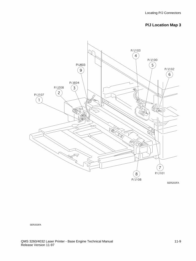
100 M3-5 Registration Sensor P/J459 MCU PWB
101 M3-7 Take Away Roll 1 Sensor P/J403 MCU PWB
102 M3-6 Tray 1 No Paper Sensor P/J459 MCU PWB
103 M3-4 Tray 1 Level Sensor P/J459 MCU PWB
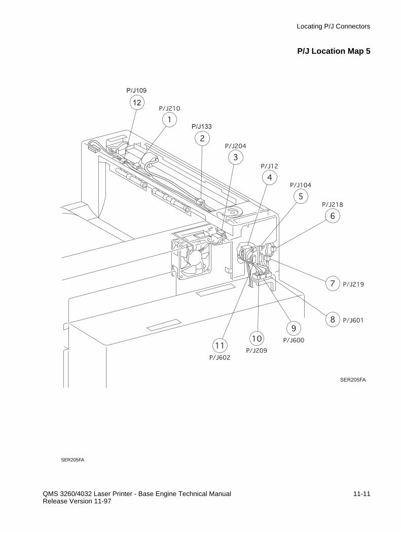
104 M5-5 Fuser Exit Sensor P/J462 MCU PWB
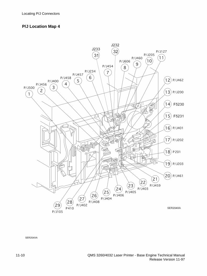
105 M4-29 Tray 1 Paper Size Sensor P/J461 MCU PWB
106 M1-1 SOS Sensor P/J456 MCU PWB
107 M3-1 MSI Size Sensor P/J403 MCU PWB
108 M3-8 MSI No Paper Sensor P/J403 MCU PWB
109 M5-12 Face Up Exit Sensor P/J462 MCU PWB
127 M4-11 MCU PWB Toner Sensor
133 M5-2 Full Stack Sensor P/J462 MCU PWB
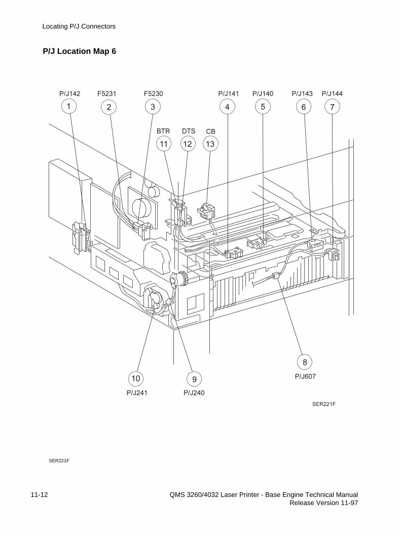
140 M6-5 Tray 2 No Paper Sensor P/J408 MCU PWB
141 M6-4 Tray 2 Level Sensor P/J408 MCU PWB
-2 QMS 3260/4032 Laser Printer - Base Engine Technical Manual Release Version 11-97
QMRe
Locating P/J Connectors
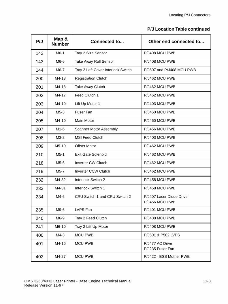
P/J Location Table continued
P/J Map & Number Connected to... Other end connected to...
142 M6-1 Tray 2 Size Sensor P/J408 MCU PWB
143 M6-6 Take Away Roll Sensor P/J408 MCU PWB
144 M6-7 Tray 2 Left Cover Interlock Switch P/J607 and P/J408 MCU PWB
200 M4-13 Registration Clutch P/J462 MCU PWB
201 M4-18 Take Away Clutch P/J462 MCU PWB
202 M4-17 Feed Clutch 1 P/J462 MCU PWB
203 M4-19 Lift Up Motor 1 P/J403 MCU PWB
204 M5-3 Fuser Fan P/J460 MCU PWB
205 M4-10 Main Motor P/J460 MCU PWB
207 M1-6 Scanner Motor Assembly P/J456 MCU PWB
208 M3-2 MSI Feed Clutch P/J403 MCU PWB
209 M5-10 Offset Motor P/J462 MCU PWB
210 M5-1 Exit Gate Solenoid P/J462 MCU PWB
218 M5-6 Inverter CW Clutch P/J462 MCU PWB
219 M5-7 Inverter CCW Clutch P/J462 MCU PWB
232 M4-32 Interlock Switch 2 P/J458 MCU PWB
233 M4-31 Interlock Switch 1 P/J458 MCU PWB
234 M4-6 CRU Switch 1 and CRU Switch 2 P/J407 Laser Diode DriverP/J456 MCU PWB
235 M9-6 LVPS Fan P/J401 MCU PWB
240 M6-9 Tray 2 Feed Clutch P/J408 MCU PWB
241 M6-10 Tray 2 Lift Up Motor P/J408 MCU PWB
400 M4-3 MCU PWB P/J501 & P502 LVPS
401 M4-16 MCU PWB P/J477 AC Drive P/J235 Fuser Fan
402 M4-27 MCU PWB P/J422 - ESS Mother PWB
S 3260/4032 Laser Printer - Base Engine Technical Manual 11-3lease Version 11-97

11
Locating P/J Connectors
P/J Location Table continued
P/J Map & Number Connected to... Other end connected to...
403 M4-22 MCU PWB P/J107 MSI Size SensorP/J108 MSI No Paper SensorP/J208 MSI Feed Clutch
404 M4-25 MCU PWB P/J611 Duplex Module
405 M4-23 MCU PWB P/J612 Mailbox or P612 Finisher
406 M4-24 MCU PWB P/J480/P/J481 HCF Cabinet PWB
407 M1-2 Laser Diode Driver P/J456 MCU PWB
408 M4-26 MCU PWB P/J140 No Paper Sensor 2P/J141 Level 2 SensorP/J142 Size 2 Paper SensorP/J143 Take Away Roll 2 SensorP/J144 Left Cover 2 Interlock SwitchP/J240 Tray 2 Feed ClutchP/J241 Tray 2 Lift Up Motor
410 M4-28 MCU PWB Type D0 Console
416 M7-6 ESS Mother PWB P/J430 Laser Diode Driver
417 M2-4M7-4
Control Panel P/J421 ESS Mother PWB
420 M7-5 ESS Mother PWB P/J501/502 LVPS PWB
421 M7-3 ESS Mother PWB P/J417 Control Panel PWB
422 M7-2 ESS Mother PWB P/J402 MCU PWB
423 M7-7 QMS Video Controller ESS Mother PWB
430 M1-3 Laser Diode Driver ESS Mother PWB
454 M4-7 MCU PWB P/J606 CRU - CRU Memory
456 M4-2 MCU PWB P/J106 SOS SensorP/J207 ROS MotorP/J234 CRU InterlockP/J407 Laser Diode Driver
457 M4-5 MCU PWB P/J500 HVPS
458 M4-4 MCU PWB P/J233 Interlocks SW1 and SW2
-4 QMS 3260/4032 Laser Printer - Base Engine Technical Manual Release Version 11-97
QMRe
Locating P/J Connectors
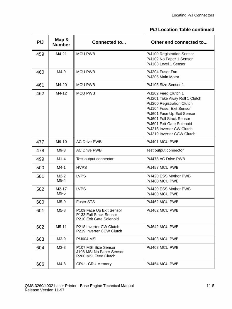
P/J Location Table continued
P/J Map & Number Connected to... Other end connected to...
459 M4-21 MCU PWB P/J100 Registration SensorP/J102 No Paper 1 SensorP/J103 Level 1 Sensor
460 M4-9 MCU PWB P/J204 Fuser FanP/J205 Main Motor
461 M4-20 MCU PWB P/J105 Size Sensor 1
462 M4-12 MCU PWB P/J202 Feed Clutch 1P/J201 Take Away Roll 1 ClutchP/J200 Registration ClutchP/J104 Fuser Exit SensorP/J601 Face Up Exit SensorP/J601 Full Stack SensorP/J601 Exit Gate SolenoidP/J218 Inverter CW ClutchP/J219 Inverter CCW Clutch
477 M9-10 AC Drive PWB P/J401 MCU PWB
478 M9-8 AC Drive PWB Test output connector
499 M1-4 Test output connector P/J478 AC Drive PWB
500 M4-1 HVPS P/J457 MCU PWB
501 M2-2M9-4
LVPS P/J420 ESS Mother PWBP/J400 MCU PWB
502 M2-17M9-5
LVPS P/J420 ESS Mother PWBP/J400 MCU PWB
600 M5-9 Fuser STS P/J462 MCU PWB
601 M5-8 P109 Face Up Exit SensorP133 Full Stack SensorP210 Exit Gate Solenoid
P/J462 MCU PWB
602 M5-11 P218 Inverter CW ClutchP219 Inverter CCW Clutch
P/J642 MCU PWB
603 M3-9 P/J604 MSI P/J403 MCU PWB
604 M3-3 P107 MSI Size SensorJ108 MSI No Paper SensorP200 MSI Feed Clutch
P/J403 MCU PWB
606 M4-8 CRU - CRU Memory P/J454 MCU PWB
S 3260/4032 Laser Printer - Base Engine Technical Manual 11-5lease Version 11-97
11
Locating P/J Connectors
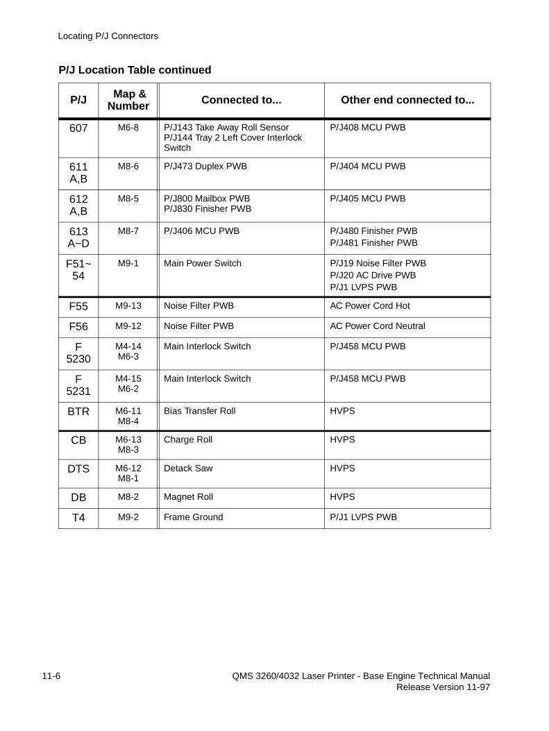
P/J Location Table continued
P/J Map & Number Connected to... Other end connected to...
607 M6-8 P/J143 Take Away Roll SensorP/J144 Tray 2 Left Cover Interlock Switch
P/J408 MCU PWB
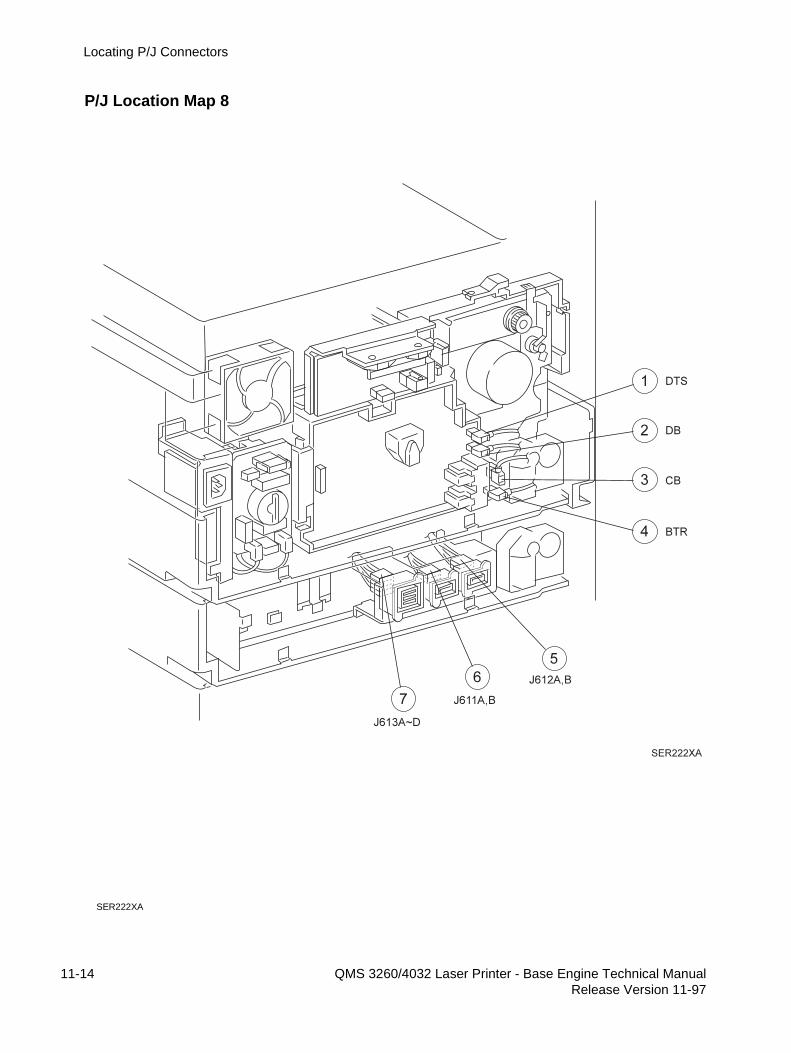
611A,B
M8-6 P/J473 Duplex PWB P/J404 MCU PWB
612A,B
M8-5 P/J800 Mailbox PWBP/J830 Finisher PWB
P/J405 MCU PWB
613A~D
M8-7 P/J406 MCU PWB P/J480 Finisher PWBP/J481 Finisher PWB
F51~54
M9-1 Main Power Switch P/J19 Noise Filter PWBP/J20 AC Drive PWBP/J1 LVPS PWB
F55 M9-13 Noise Filter PWB AC Power Cord Hot
F56 M9-12 Noise Filter PWB AC Power Cord Neutral
F5230
M4-14M6-3
Main Interlock Switch P/J458 MCU PWB
F5231
M4-15M6-2
Main Interlock Switch P/J458 MCU PWB
BTR M6-11M8-4
Bias Transfer Roll HVPS
CB M6-13M8-3
Charge Roll HVPS
DTS M6-12M8-1
Detack Saw HVPS
DB M8-2 Magnet Roll HVPS
T4 M9-2 Frame Ground P/J1 LVPS PWB
-6 QMS 3260/4032 Laser Printer - Base Engine Technical Manual Release Version 11-97

QMRe
Locating P/J Connectors
P/J Location Map 1
SER200F
S 3260/4032 Laser Printer - Base Engine Technical Manual 11-7lease Version 11-97
11
Locating P/J Connectors
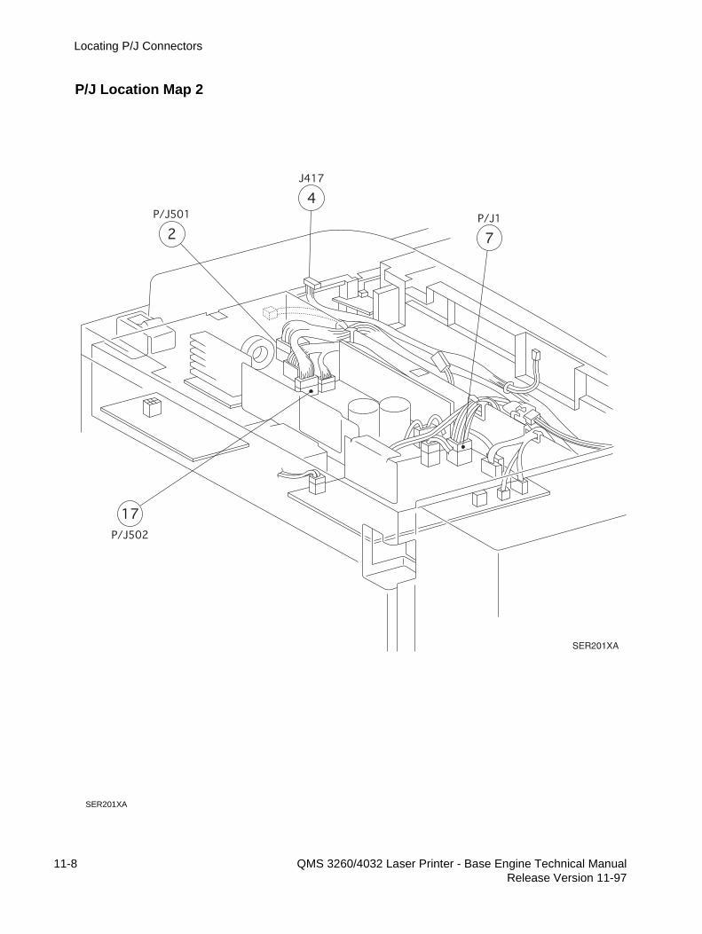
P/J Location Map 2
SER201XA
-8 QMS 3260/4032 Laser Printer - Base Engine Technical Manual Release Version 11-97
QMRe
Locating P/J Connectors
P/J Location Map 3
SER203FA
S 3260/4032 Laser Printer - Base Engine Technical Manual 11-9lease Version 11-97
11
Locating P/J Connectors
P/J Location Map 4
SER204XA
-10 QMS 3260/4032 Laser Printer - Base Engine Technical Manual Release Version 11-97
QMRe
Locating P/J Connectors
P/J Location Map 5
SER205FA
S 3260/4032 Laser Printer - Base Engine Technical Manual 11-11lease Version 11-97
11
Locating P/J Connectors
P/J Location Map 6
SER221F
-12 QMS 3260/4032 Laser Printer - Base Engine Technical Manual Release Version 11-97

QMRe
Locating P/J Connectors
P/J Location Map 7
SER220XA
S 3260/4032 Laser Printer - Base Engine Technical Manual 11-13lease Version 11-97
11
Locating P/J Connectors
P/J Location Map 8
SER222XA
-14 QMS 3260/4032 Laser Printer - Base Engine Technical Manual Release Version 11-97

QMRe
Locating P/J Connectors
P/J Location Map 9
SER219F
S 3260/4032 Laser Printer - Base Engine Technical Manual 11-15lease Version 11-97

11
Locating P/J Connectors
Blank Page
-16 QMS 3260/4032 Laser Printer - Base Engine Technical Manual Release Version 11-97

QMRe
Parts List
Section 12 - Parts List Contents
PL1.1 Top Cover Assembly . . . . . . . . . . . . . . . . . . . . . . . . . . . . . . . . . . . . . . . . . . . . . . . . . . . . . . 12-4PL1.2 Front Cover . . . . . . . . . . . . . . . . . . . . . . . . . . . . . . . . . . . . . . . . . . . . . . . . . . . . . . . . . . . . . 12-6PL1.3 Rear, Left, and Right Covers . . . . . . . . . . . . . . . . . . . . . . . . . . . . . . . . . . . . . . . . . . . . . . . . 12-8PL2.1 Tray Unit - Paper Stack . . . . . . . . . . . . . . . . . . . . . . . . . . . . . . . . . . . . . . . . . . . . . . . . . . . 12-10PL2.2 Tray Unit - End Guide . . . . . . . . . . . . . . . . . . . . . . . . . . . . . . . . . . . . . . . . . . . . . . . . . . . . 12-12PL3.1 Tray Interface - Tray 1 . . . . . . . . . . . . . . . . . . . . . . . . . . . . . . . . . . . . . . . . . . . . . . . . . . . . 12-14PL3.2 Paper Pick Up - Tray 1 . . . . . . . . . . . . . . . . . . . . . . . . . . . . . . . . . . . . . . . . . . . . . . . . . . . . 12-16PL3.3 Retard and Take Away - Tray 1 . . . . . . . . . . . . . . . . . . . . . . . . . . . . . . . . . . . . . . . . . . . . . 12-18PL3.4 Tray Interface - Tray 2 . . . . . . . . . . . . . . . . . . . . . . . . . . . . . . . . . . . . . . . . . . . . . . . . . . . . 12-20PL3.5 Paper Pick Up - Tray 2 . . . . . . . . . . . . . . . . . . . . . . . . . . . . . . . . . . . . . . . . . . . . . . . . . . . . 12-22PL3.6 Retard and Take Away - Tray 2 . . . . . . . . . . . . . . . . . . . . . . . . . . . . . . . . . . . . . . . . . . . . . 12-24PL3.7 Feed Drive Transmission . . . . . . . . . . . . . . . . . . . . . . . . . . . . . . . . . . . . . . . . . . . . . . . . . . 12-26PL4.1 Multi Sheet Inserter and MSI/Duplex Support . . . . . . . . . . . . . . . . . . . . . . . . . . . . . . . . . . 12-28PL4.2 MSI Feeder Assembly . . . . . . . . . . . . . . . . . . . . . . . . . . . . . . . . . . . . . . . . . . . . . . . . . . . . 12-30PL4.3 Upper Feeder Assembly . . . . . . . . . . . . . . . . . . . . . . . . . . . . . . . . . . . . . . . . . . . . . . . . . . 12-32PL4.4 MSI Tray Assembly . . . . . . . . . . . . . . . . . . . . . . . . . . . . . . . . . . . . . . . . . . . . . . . . . . . . . . 12-34PL5.1 Tray 1 Frame and Left Cover . . . . . . . . . . . . . . . . . . . . . . . . . . . . . . . . . . . . . . . . . . . . . . . 12-36PL5.2 Tray 2 Frame and Left Cover . . . . . . . . . . . . . . . . . . . . . . . . . . . . . . . . . . . . . . . . . . . . . . . 12-38PL6.1 Registration . . . . . . . . . . . . . . . . . . . . . . . . . . . . . . . . . . . . . . . . . . . . . . . . . . . . . . . . . . . . 12-40PL6.2 Left Upper Cover Assembly . . . . . . . . . . . . . . . . . . . . . . . . . . . . . . . . . . . . . . . . . . . . . . . . 12-42PL6.3 Transport Chute Assembly . . . . . . . . . . . . . . . . . . . . . . . . . . . . . . . . . . . . . . . . . . . . . . . . 12-44PL7.1 ROS Assembly . . . . . . . . . . . . . . . . . . . . . . . . . . . . . . . . . . . . . . . . . . . . . . . . . . . . . . . . . 12-46PL7.2 Xerography and Development . . . . . . . . . . . . . . . . . . . . . . . . . . . . . . . . . . . . . . . . . . . . . . 12-48PL8.1 Fuser Assembly . . . . . . . . . . . . . . . . . . . . . . . . . . . . . . . . . . . . . . . . . . . . . . . . . . . . . . . . . 12-50PL9.1 Exit Lower Chute . . . . . . . . . . . . . . . . . . . . . . . . . . . . . . . . . . . . . . . . . . . . . . . . . . . . . . . . 12-52PL9.2 Offset Roller. . . . . . . . . . . . . . . . . . . . . . . . . . . . . . . . . . . . . . . . . . . . . . . . . . . . . . . . . . . . 12-54PL9.3 Exit Upper Chute Assembly. . . . . . . . . . . . . . . . . . . . . . . . . . . . . . . . . . . . . . . . . . . . . . . . 12-56PL9.4 Exit Drive Assembly. . . . . . . . . . . . . . . . . . . . . . . . . . . . . . . . . . . . . . . . . . . . . . . . . . . . . . 12-58PL10.1 Main Drive Assembly . . . . . . . . . . . . . . . . . . . . . . . . . . . . . . . . . . . . . . . . . . . . . . . . . . . . . 12-60PL10.2 Fuser Drive Assembly . . . . . . . . . . . . . . . . . . . . . . . . . . . . . . . . . . . . . . . . . . . . . . . . . . . . 12-62PL11.1 Power Inlet and LVPS . . . . . . . . . . . . . . . . . . . . . . . . . . . . . . . . . . . . . . . . . . . . . . . . . . . . 12-64PL11.2 HVPS and MCU PWB . . . . . . . . . . . . . . . . . . . . . . . . . . . . . . . . . . . . . . . . . . . . . . . . . . . . 12-66PL11.3 ESS Assembly . . . . . . . . . . . . . . . . . . . . . . . . . . . . . . . . . . . . . . . . . . . . . . . . . . . . . . . . . . 12-68PL11.4 Harness . . . . . . . . . . . . . . . . . . . . . . . . . . . . . . . . . . . . . . . . . . . . . . . . . . . . . . . . . . . . . . . 12-70
S 3260/4032 Laser Printer - Base Engine Technical Manual 12-1lease Version 11-97

12
Parts List
Section 12 - Parts List
Using the Parts List
1. The numbers shown in each illustration correspond to the parts list number for that illustration.
2. Throughout this manual, parts are identified by the prefix “PL”, followed by a number, a decimal point,and another number. For example, PL3.12 means the part is item 12 of parts list 3.
3. The capital letters “C”, “E”, "KL", and “S” shown in an illustration stand for C-ring, E-ring, Clamp, andScrew, respectively.
4. A shaded triangle ▼ in an illustration indicates the item is part of an assembly.
5. The notation “with X~Y ” following an part name indicates an assembly that is made up of componentsX through Y. For example, “1 (with 2~4)” means part 1 consists of part 2, part 3, and part 4.
6. The symbol $ following a part name indicates the part is an FX Recommended Part and is constantlystocked and readily available. Other parts may be stocked according to the needs of each individualOEM client.
7. An asterisk * following a part name indicates the page contains a note about this part.
8. The notation “J1<>J2 and P2 ” is attached to a wire harness. It indicates that connector jack 1 isattached to one end of the wire harness and connector jack 2 is attached to the other end that isplugged into plug 2.
9. An RRP number appears at the end of a part line if the technical manual contains a removal andreplacement procedure for that part or module.
-2 QMS 3260/4032 Laser Printer - Base Engine Technical Manual Release Version 11-97

QMRe
Parts List
Blank Page
S 3260/4032 Laser Printer - Base Engine Technical Manual 12-3lease Version 11-97
12
Parts List
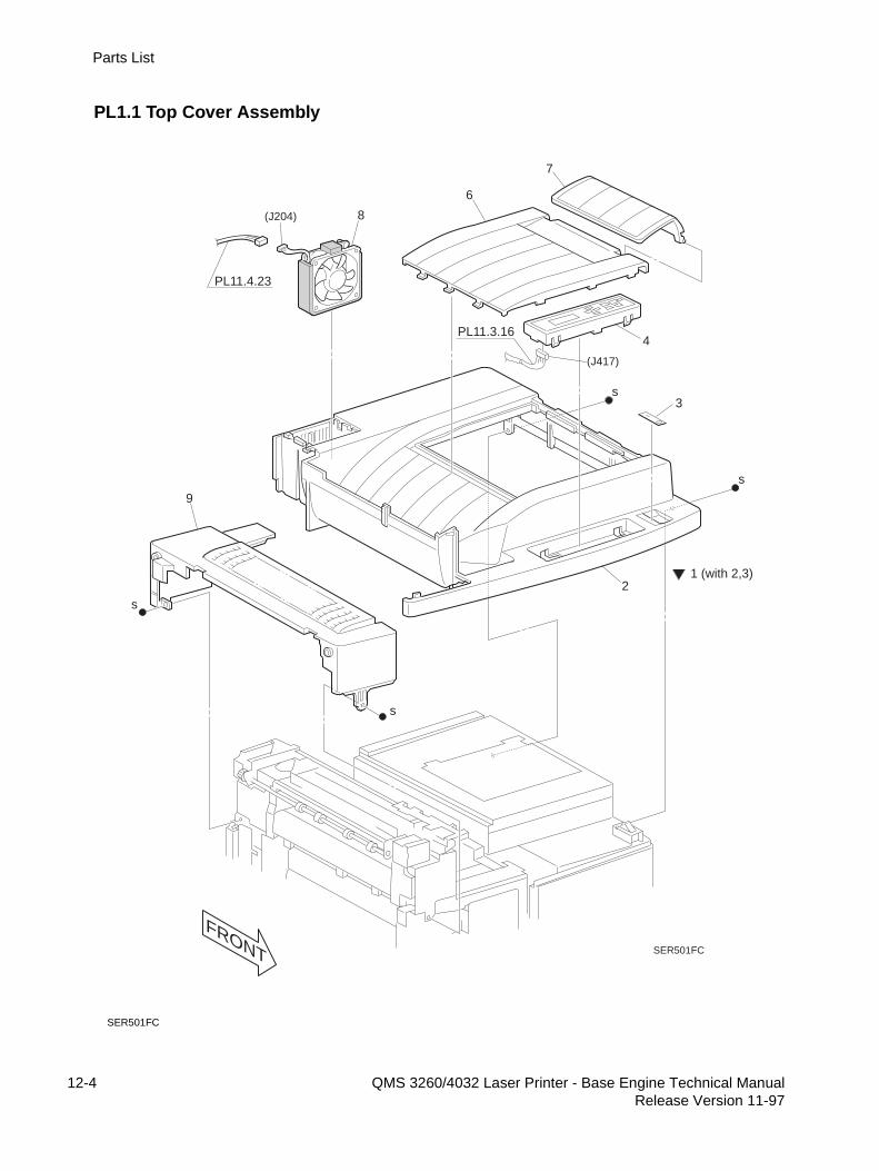
PL1.1 Top Cover Assembly
SER501FC
8
7
6
4
3
21 (with 2,3)
9
s
s
s
s
SER501FC
FRONT
(J204)
(J417)
PL11.4.23
PL11.3.16
-4 QMS 3260/4032 Laser Printer - Base Engine Technical Manual Release Version 11-97

QMRe
Parts List
PL1.1 Top Cover Assembly1. COVER ASSEMBLY (with 2 and 3)
2. TOP COVER
3. LABEL SWITCH
4. CONSOLE PANEL
5. - -
6. COVER ESS
7. STOPPER
8. FAN ASSEMBLY FUSER
9. COVER-FUSER FULL
S 3260/4032 Laser Printer - Base Engine Technical Manual 12-5lease Version 11-97

12
Parts List
PL1.2 Front Cover
SER502XB
-6 QMS 3260/4032 Laser Printer - Base Engine Technical Manual Release Version 11-97
QMRe
Parts List
PL1.2 Front Cover1. COVER ASSEMBLY FL
2. SPRING TORSION
3. COVER F/R
4. PLATE MAGNET
5. DUCT BOTTOM
6. - -
7. - -
8. STUD DOCKING
9. SPRING EME FRONT
10. BRACKET DOCKING LEFT
11. - -
12. BRACKET DOCKING REAR
99. KIT TRAY 2 MOUNTING (8, 10, 12)
S 3260/4032 Laser Printer - Base Engine Technical Manual 12-7lease Version 11-97

12
Parts List
PL1.3 Rear, Left, and Right Covers
SER503XB
-8 QMS 3260/4032 Laser Printer - Base Engine Technical Manual Release Version 11-97

QMRe
Parts List
PL1.3 Rear, Left, and Right Covers1. COVER INNER, LH
2. COVER RH
3. COVER ASSEMBLY, REAR OEM
4. COVER REAR 1TM, OEM
S 3260/4032 Laser Printer - Base Engine Technical Manual 12-9lease Version 11-97
12
Parts List
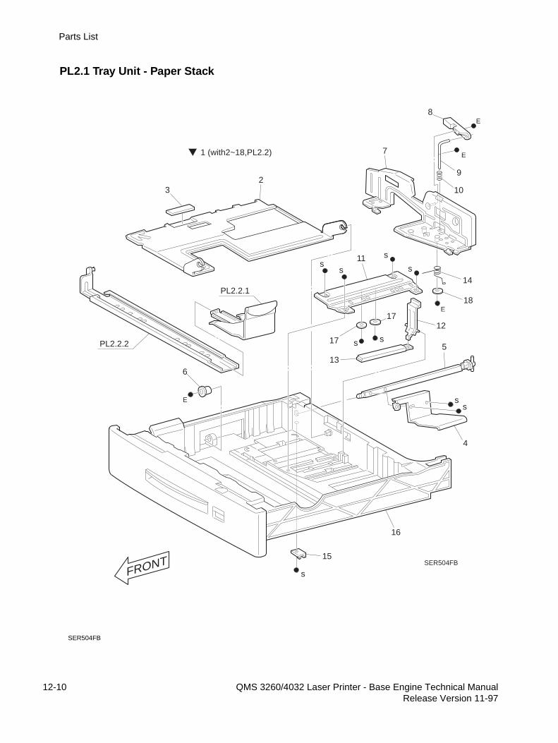
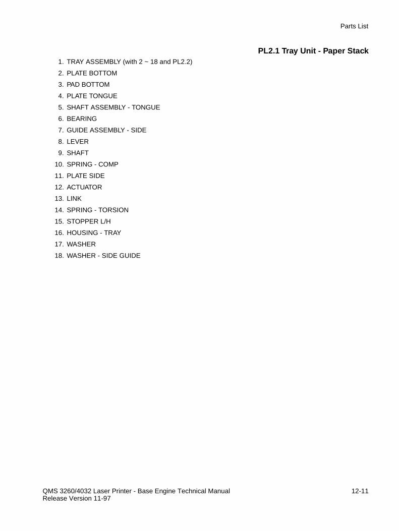
PL2.1 Tray Unit - Paper Stack
SER504FB
FRONT
23
7
8
9
10
E
E
11
14
12
17
17
13
5
4
6
PL2.2.1
PL2.2.2
15
16
s
ss
E
E
s s
ss
s
s
1 (with2~18,PL2.2)
SER504FB
18
-10 QMS 3260/4032 Laser Printer - Base Engine Technical Manual Release Version 11-97
QMRe
Parts List
PL2.1 Tray Unit - Paper Stack1. TRAY ASSEMBLY (with 2 ~ 18 and PL2.2)
2. PLATE BOTTOM
3. PAD BOTTOM
4. PLATE TONGUE
5. SHAFT ASSEMBLY - TONGUE
6. BEARING
7. GUIDE ASSEMBLY - SIDE
8. LEVER
9. SHAFT
10. SPRING - COMP
11. PLATE SIDE
12. ACTUATOR
13. LINK
14. SPRING - TORSION
15. STOPPER L/H
16. HOUSING - TRAY
17. WASHER
18. WASHER - SIDE GUIDE
S 3260/4032 Laser Printer - Base Engine Technical Manual 12-11lease Version 11-97
12
Parts List
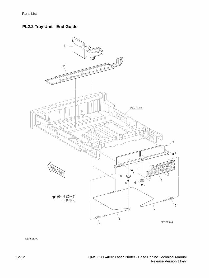
PL2.2 Tray Unit - End Guide
SER505XA
-12 QMS 3260/4032 Laser Printer - Base Engine Technical Manual Release Version 11-97

QMRe
Parts List
PL2.2 Tray Unit - End Guide1. GUIDE ASSEMBLY - END
2. PLATE ASSEMBLY - END
3. ACTUATOR ASSEMBLY
4. CABLE ASSEMBLY
5. SPRING - EXTENSION
6. PULLEY
7. GUIDE ACTUATOR
99. KIT CASSETTE CABLES (with 4 (Qty 2) and 5 (Qty 2)
S 3260/4032 Laser Printer - Base Engine Technical Manual 12-13lease Version 11-97

12
Parts List
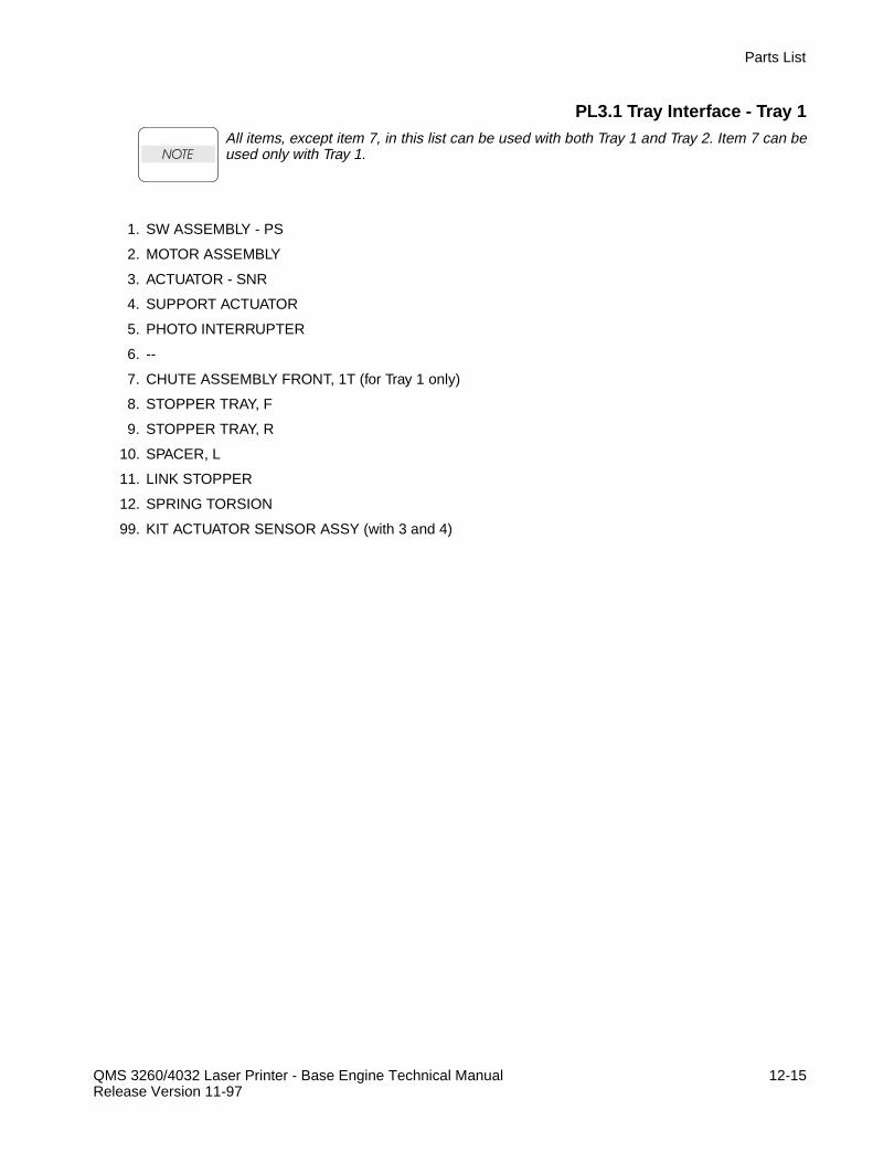
PL3.1 Tray Interface - Tray 1
SER506XD
-14 QMS 3260/4032 Laser Printer - Base Engine Technical Manual Release Version 11-97
QMRe
Parts List
PL3.1 Tray Interface - Tray 1All items, except item 7, in this list can be used with both Tray 1 and Tray 2. Item 7 can beused only with Tray 1.
1. SW ASSEMBLY - PS
2. MOTOR ASSEMBLY
3. ACTUATOR - SNR
4. SUPPORT ACTUATOR
5. PHOTO INTERRUPTER
6. --
7. CHUTE ASSEMBLY FRONT, 1T (for Tray 1 only)
8. STOPPER TRAY, F
9. STOPPER TRAY, R
10. SPACER, L
11. LINK STOPPER
12. SPRING TORSION
99. KIT ACTUATOR SENSOR ASSY (with 3 and 4)
S 3260/4032 Laser Printer - Base Engine Technical Manual 12-15lease Version 11-97
12
Parts List
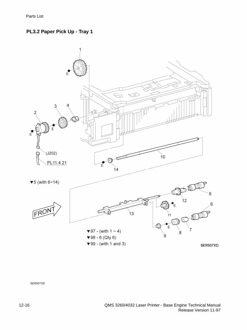
PL3.2 Paper Pick Up - Tray 1
SER507XD
-16 QMS 3260/4032 Laser Printer - Base Engine Technical Manual Release Version 11-97

QMRe
Parts List
PL3.2 Paper Pick Up - Tray 1All items, except items 3 and 4, in this list can be used with both Tray 1 and Tray 2. Items 3and 4 can be used only with Tray 1.
1. GEAR - 46T M/N
2. CLUTCH ASSEMBLY
3. GEAR ASSEMBLY 28T M/N (for Tray 1 only)
4. CLUTCH ONE-WAY (for Tray 1 only)
5. FEEDER ASSEMBLY M/N, (with 6 ~ 14)
6. ROLL ASSEMBLY
7. CLUTCH ASSEMBLY O.W.
8. CLUTCH GEAR 25T
9. BEARING
10. SHAFT FEED M/N
11. GEAR 31T
12. GEAR 25T
13. SUPPORT ASSEMBLY NUDGER
14. BEARING
97. KIT TRAY 1 CLUTCH (1 ~ 4)
98. KIT FEED ROLL (with 6, Qty 6)
99. KIT PICK UP GEAR TRAY 1 (with 1 and 3)
S 3260/4032 Laser Printer - Base Engine Technical Manual 12-17lease Version 11-97

12
Parts List
PL3.3 Retard and Take Away- Tray 1
SER508XE
-18 QMS 3260/4032 Laser Printer - Base Engine Technical Manual Release Version 11-97

QMRe
Parts List
PL3.3 Retard and Take Away- Tray 1
1. RETARD ASSEMBLY, 4 (with 2 ~8)
2. GEAR 22T
3. SHAFT ASSEMBLY RET
4. BEARING
5. ROLL ASSEMBLY
6. SPACER
7. CLUTCH ASSEMBLY - FRICTION
8. SUPPORT RETARD
9. BEARING
10. GEAR 22
11. SPACER
12. GEAR STOPPER
13. BEARING, R
14. BEARING, C
15. ROLLER ASSEMBLY S/F
16. BEARING
17. BEARING
18. CHUTE ASSEMBLY FEED, OUT
19. CHUTE ASSEMBLY FEED, IN
20. GEAR 22/20, IOT H/N
21. SUPPORT ASSEMBLY, SPRING
22. SPRING
23. RETARD FRAME
98. RETARD ASSEMBLY TRAY 1 HIGH (with 1 and 9 ~ 23)
99. KIT TAKE AWAY GEAR TRAY 1 (with 2, 10, and 20)
S 3260/4032 Laser Printer - Base Engine Technical Manual 12-19lease Version 11-97

12
Parts List
PL3.4 Tray Interface - Tray 2
SER509XD
-20 QMS 3260/4032 Laser Printer - Base Engine Technical Manual Release Version 11-97

QMRe
Parts List
PL3.4 Tray Interface - Tray 2All items, except item 7, in this list can be used with both Tray 1 and Tray 2. Item 7 can beused only with Tray 2.
1. SW ASSEMBLY PS
2. MOTOR ASSEMBLY
3. ACTUATOR - SNR
4. SUPPORT ACTUATOR
5. PHOTO INTERRUPTER
6. --
7. CHUTE ASSEMBLY FRONT, 2T (for Tray 2 only)
8. STOPPER, TRAY F
9. STOPPER, TRAY R
10. SPACER, L
11. LINK STOPPER
12. SPRING TORSION
99. KIT ACTUATOR SENSOR ASSY (with 3 and 4)
S 3260/4032 Laser Printer - Base Engine Technical Manual 12-21lease Version 11-97

12
Parts List
PL3.5 Paper Pick Up - Tray 2
SER510XD
-22 QMS 3260/4032 Laser Printer - Base Engine Technical Manual Release Version 11-97

QMRe
Parts List
PL3.5 Paper Pick Up - Tray 2All items, except items 3 and 4, in this list can be used with both Tray 1 and Tray 2. Items 3and 4 can be used only with Tray 2 and the High Capacity Feeder.
1. GEAR 46T M/N
2. CLUTCH ASSEMBLY
3. GEAR 28T M/N (for Tray 2 and High Capacity Feeder only)
4. BEARING FEED (for Tray 2 and High Capacity Feeder only)
5. FEEDER ASSEMBLY M/N, (with 6 ~ 14)
6. ROLL ASSEMBLY
7. CLUTCH ASSEMBLY OW
8. CLUTCH GEAR 25T
9. BEARING
10. SHAFT FEED M/N
11. GEAR 31T
12. GEAR 25T
13. SUPPORT ASSEMBLY NUDGER
14. BEARING
97. KIT TRAY 2 CLUTCH (with 1 ~ 4)
98. KIT FEED ROLL (Qty 6 of item 6)
99. KIT PICKUP GEAR TRAY 2 (with 1 and 3)
S 3260/4032 Laser Printer - Base Engine Technical Manual 12-23lease Version 11-97
12
Parts List
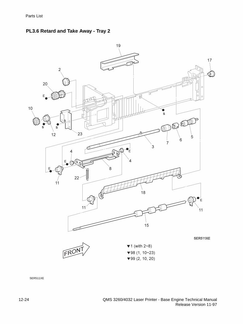
PL3.6 Retard and Take Away - Tray 2
SER511XE
-24 QMS 3260/4032 Laser Printer - Base Engine Technical Manual Release Version 11-97

QMRe
Parts List
PL3.6 Retard and Take Away - Tray 2
1. RETARD ASSEMBLY, (with 2 ~ 8)
2. GEAR 22T
3. SHAFT ASSEMBLY RET
4. BEARING
5. ROLL ASSEMBLY
6. SPACER
7. CLUTCH ASSEMBLY - FRICTION
8. SUPPORT RETARD
9. - -
10. GEAR 22
11. BEARING
12. GEAR STOPPER
13. --
14. --
15. ROLL ASSEMBLY, T/A
16. --
17. BEARING
18. CHUTE - F/O, 1TM,E
19. CHUTE FEED IN
20. GEAR 22/20, C M/N
21. --
22. SPRING
23. BRACKET
98. KIT RETARD TAKEAWAY TRAY 2 (with 1, and 10~23)
99. KIT TAKE AWAY GEAR TRAY 2 (with 2, 10, and 20)
S 3260/4032 Laser Printer - Base Engine Technical Manual 12-25lease Version 11-97

12
Parts List
PL3.7 Feed Drive Transmission
SER512XE
-26 QMS 3260/4032 Laser Printer - Base Engine Technical Manual Release Version 11-97

QMRe
Parts List
PL3.7 Feed Drive Transmission
1. GEAR 16T
2. GEAR 30T
3. SHAFT C/L T/A
4. - -
5. SUPPORT C/L T/A
6. GEAR 31T
7. GEAR 33T
8. GEAR 16/22
9. LINK ASSEMBLY
10. SPRING TORSION
11. BEARING
12. HARNESS CLAMP
99. KIT FEED DRIVE REPAIR (with 1, 2, and 6 ~ 11)
S 3260/4032 Laser Printer - Base Engine Technical Manual 12-27lease Version 11-97

12
Parts List
PL4.1 Multi Sheet Inserter and MSI/Duplex Support
SER513FC
SER513FC
7 (with 8~12,PL 4.2)
FRONT
1
23
45
6
8
9
10
11
12
s
ss
s
s
s
s
s
ss
PL4.2
PL4.4
(J604)
(P603)
s
PL11.4.15
-28 QMS 3260/4032 Laser Printer - Base Engine Technical Manual Release Version 11-97

QMRe
Parts List
PL4.1 Multi Sheet Inserter and MSI/Duplex Support
1. SUPPORT FRONT COVER
2. SUPPORT REAR COVER
3. MSI/DUPLEX SUPPORT ASSEMBLY
4. HARNESS ASSEMBLY DRAWER (J603 <> J604)
5. SPRING, DAMPER F
6. SPRING DAMPER R
7. MULTI SHEET INSERTER ASSEMBLY (with 8 ~ 12 and PL4.2)
8. MSI TOP COVER
9. MULTI SHEET TRAY SUPPORT
10. MULTI SHEET INSERTER HINGE STUD
11. MULTI SHEET TRAY SPRING
12. MSI HARNESS CLAMP
S 3260/4032 Laser Printer - Base Engine Technical Manual 12-29lease Version 11-97

12
Parts List
PL4.2 MSI Feeder Assembly
SER514FB
SER514FB
2
3
4
5
7
8 9
6
10
11
12
13
14
15
15
16
17
S
S
S
S
S
SS
E
E
E
E
PL 4.3
1 (with 2~17,PL 4.3)
FRONT
PL 4.3.13
-30 QMS 3260/4032 Laser Printer - Base Engine Technical Manual Release Version 11-97

QMRe
Parts List
PL4.2 MSI Feeder Assembly
1. MSI FEEDER ASSEMBLY
2. MSI LINK GEAR
3. MSI DRIVE GEAR ASSEMBLY
4. MSI DRIVE LINK SPRING
5. MSI TIE PLATE
6. MSI PAD
7. MSI PAD PIN
8. MSI PAD SHAFT
9. MSI PAD SPRING
10. MSI PAPER GUIDE
11. MSI BRACKET
12. MSI HOOK BRACKET FRONT
13. MSI HOOK BRACKET REAR
14. LATCH - FRONT
15. MULTI SHEET INSERTER HOOK SPRING
16. MSI LOWER CHUTE
17. LATCH - REAR
S 3260/4032 Laser Printer - Base Engine Technical Manual 12-31lease Version 11-97

12
Parts List
PL4.3 Upper Feeder Assembly
SER515FB
SER515FB
2
3
4
5
6
7
8
8
9
10 11
12
12
13
15
16
1718
19
19
20
21
22
S
SS
E
E
E
E
E
E
E
E
2324
25
26
1 (with 2~26)
14 (with 15~25)
(P208)
(P604)
(J208)
(J108)
(P107)
PL4.1.12
PL4.4.4
-32 QMS 3260/4032 Laser Printer - Base Engine Technical Manual Release Version 11-97

QMRe
Parts List
PL4.3 Upper Feeder Assembly
1. UPPER FEEDER ASSEMBLY (with 2 ~ 26)
2. MSI FEED CLUTCH
3. MSI FEED BEARING REAR 1
4. MSI FEED SHAFT
5. MSI FEED GEAR
6. MSI FEED BEARING REAR 2
7. MSI FEED SPRING
8. MSI FEED BEARING FRONT
9. MSI FEED ROLLER
10. MSI NO PAPER SENSOR
11. MSI NO PAPER SENSOR BRACKET
12. MSI STOPPER
13. MSI WIRE HARNESS (P604 < > J108/P107/P208)
14. MSI NUDGER ROLLER ASSEMBLY (with 15 ~ 25)
15. MSI NUDGER ROLLER SUPPORT
16. MSI NUDGER GEAR COVER
17. MSI NUDGER GEAR
18. MSI NUDGER BEARING REAR
19. MSI GATE
20. MSI NUDGER ROLLER BEARING FRONT
21. MSI NUDGER ROLLER SHAFT
22. MSI NUDGER ROLLER
23. MSI FRICTION CLUTCH
24. MSI FRICTION CLUTCH SPACER
25. MSI FRICTION CLUTCH GEAR
26. UPPER FEEDER FRAME
S 3260/4032 Laser Printer - Base Engine Technical Manual 12-33lease Version 11-97

12
Parts List
PL4.4 MSI Tray Assembly
SER516XB
-34 QMS 3260/4032 Laser Printer - Base Engine Technical Manual Release Version 11-97

QMRe
Parts List
PL4.4 MSI Tray Assembly
1. MSI TRAY ASSEMBLY (with 2 ~ 9)
2. MSI PAD
3. MSI SIDE GUIDE
4. MSI SIZE SENSOR ASSEMBLY
5. MSI SIZE GUIDE SPRING
6. MSI SIZE GUIDE LINK
7. MSI TRAY LOWER COVER
8. MSI TRAY
9. MSI TRAY UPPER COVER
S 3260/4032 Laser Printer - Base Engine Technical Manual 12-35lease Version 11-97
12
Parts List
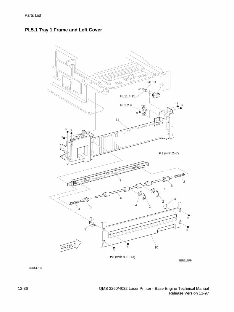
PL5.1 Tray 1 Frame and Left Cover
SER517FB
SER517FB
2
2
3
34
45
5
6
7
9
10
11
12
S
S
SS
1 (with 2~7)
8 (with 9,10,13)
FRONT
S
S S
SS
S
(J101)
13
PL1.2.9
PL11.4.15
-36 QMS 3260/4032 Laser Printer - Base Engine Technical Manual Release Version 11-97

QMRe
Parts List
PL5.1 Tray 1 Frame and Left Cover
1. PINCH ROLL ASSEMBLY (with 2 ~ 7)
2. HOLDING SPRING
3. SHAFT SPRING
4. CENTER BEARING
5. END BEARING
6. PINCH ROLLER
7. PINCH ROLLER BRACKET
8. COVER ASSEMBLY L/H, LOW (with 9, 10, and 13)
9. GROUNDING METAL
10. LEFT MIDDLE COVER
11. FRAME LH
12. TAKE AWAY SENSOR 1
13. TAKE AWAY SENSOR SHIELD
S 3260/4032 Laser Printer - Base Engine Technical Manual 12-37lease Version 11-97

12
Parts List
PL5.2 Tray 2 Frame and Left Cover
SER518FC
SER518FC
2
4
4
55
77
9
10
11
12
13
14
15
16
22
17
17
18
19
20
S
S
S
SS
S
S
S
S
S
SS
S
S
S
S
21
21
8
6
1 (with 2,3,9,10,11,14,23)
3 (with 4~8,21)
(J144)
(J143)
(J607)
23
PL11.4.13
-38 QMS 3260/4032 Laser Printer - Base Engine Technical Manual Release Version 11-97

QMRe
Parts List
PL5.2 Tray 2 Frame and Left Cover
1. LEFT LOWER COVER ASSEMBLY (with 2, 3, 9 ~11, 14, and 23)
2. LEFT LOWER COVER
3. PINCH ROLL ASSEMBLY (with 4 ~ 8, and 21)
4. PINCH ROLL END BEARING
5. PINCH ROLL CENTER BEARING
6. PINCH ROLLER
7. PINCH ROLL SPRING
8. PINCH ROLL BRACKET
9. LEFT LOWER COVER HANDLE ASSEMBLY
10. FRONT FRAME
11. REAR FRAME
12. FRONT HINGE
13. REAR HINGE
14. FEED OUT CHUTE
15. LEFT LOWER COVER INTERLOCK SWITCH
16. TRAY 2 WELL TIE PLATE
17. SPRING - EME
18. CAP
19. TAKE AWAY SENSOR
20. SUPPORT - REAR
21. WASHER
22. INTERLOCK/SENSOR HARNESS (J607 < > J143/J144)
23. TAKE AWAY SENSOR SHIELD
S 3260/4032 Laser Printer - Base Engine Technical Manual 12-39lease Version 11-97

12
Parts List
PL6.1 Registration
SER519FB
SER519FB
4 (with 5,6)
1
2
2
3
5
6
7
8
9
S
S
S
S
E
E
EFRONT
(J100)
(J200) PL11.4.18
PL11.4.21
-40 QMS 3260/4032 Laser Printer - Base Engine Technical Manual Release Version 11-97

QMRe
Parts List
PL6.1 Registration
1. CLUTCH ASSEMBLY REGISTRATION
2. BEARING
3. ROLLER ASSEMBLY REGISTRATION
4. CHUTE ASSEMBLY REGISTRATION ( 5 and 6)
5. CHUTE REGISTRATION
6. ELIMINATOR
7. SENSOR
8. RESISTOR ASSEMBLY
9. FRAME - L/H
S 3260/4032 Laser Printer - Base Engine Technical Manual 12-41lease Version 11-97

12
Parts List
PL6.2 Left Upper Cover Assembly
SER520FA
SER520FA
1
2
4
5
6
6
8
8
9
10
11
12
13
13
14
14
S
S
S
S
S
S
S
3 (with 4~14,PL 6.3)
7 (with 8~13)
PL 6.3FRONT
-42 QMS 3260/4032 Laser Printer - Base Engine Technical Manual Release Version 11-97

QMRe
Parts List
PL6.2 Left Upper Cover Assembly
1. SHAFT - HINGE
2. SHAFT - HINGE REAR M/N
3. COVER ASSEMBLY L/H, (with 4 ~ 14, PL 6.3)
4. CHUTE LOWER
5. GUIDE PAPER
6. SPRING COMP
7. CHUTE ASSEMBLY L/H (with 8 ~ 13)
8. SPRING EXTENSION
9. ROLLER ASSEMBLY - REGISTRATION L/H
10. CHUTE ASSEMBLY - REGISTRATION L/H
11. GUIDE PAPER
12. GUIDE PAPER
13. PULLEY
14. SUPPORT - L/H COVER
S 3260/4032 Laser Printer - Base Engine Technical Manual 12-43lease Version 11-97

12
Parts List
PL6.3 Transport Chute Assembly
SER521F
-44 QMS 3260/4032 Laser Printer - Base Engine Technical Manual Release Version 11-97

QMRe
Parts List
PL6.3 Transport Chute Assembly
1. BTR SLEEVE SPRING IN
2. TRANSPORT CHUTE
3. PLATE ELIMINATOR
4. BTR SLEEVE SPRING OUT
5. BTR SLEEVE
6. TRANSPORT CHUTE SPRING
7. TRANSPORT CHUTE ROD
8. TRANSPORT CHUTE INLET
9. COVER ASSEMBLY L/H,
10. PAD - 1
11. BRACKET - L/H
12. PLATE - CONTACT, L/H
13. PLATE - CONTACT - L/H, C
14. FRAME - L/H, F
15. FRAME - L/H, R
16. HANDLE ASSEMBLY - L/H
S 3260/4032 Laser Printer - Base Engine Technical Manual 12-45lease Version 11-97
12
Parts List
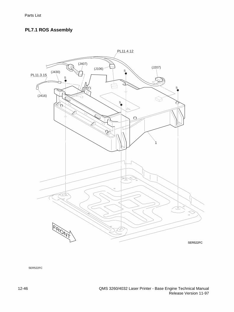
PL7.1 ROS Assembly
SER522FC
SER522FC
1
S
S
S
S
FRONT
(J207)(J106)
(J407)
(J430)
(J416)
PL11.4.12
PL11.3.15
-46 QMS 3260/4032 Laser Printer - Base Engine Technical Manual Release Version 11-97

QMRe
Parts List
PL7.1 ROS Assembly
1. ROS ASSEMBLY
S 3260/4032 Laser Printer - Base Engine Technical Manual 12-47lease Version 11-97

12
Parts List
PL7.2 Xerography and Development
SER523FC
SER523FC
2
3
3
4
5
67
9
10
11 1213
14
15
15
1718
19
19
20
20
S
S
S
S
S
S
S
SSS
S
E
24
29
27
28
22
25
21
30
PL 6.3
8 (with 9~11)
1 (with 2~7)
23 (with 24,25)
16 (with 17~20)
FRONT
(J232)
(J458)
(F5230)
(F5231)
(J234)
(J454)(J606)
(J233)
(J127)
PL11.4.20
PL11.4.12
PL11.2.26
PL11.2.26
-48 QMS 3260/4032 Laser Printer - Base Engine Technical Manual Release Version 11-97

QMRe
Parts List
PL7.2 Xerography and Development
1. BTR ASSEMBLY (with 2 ~ 7)
2. BTR FRONT LEVER
3. BTR ROLL
4. BTR
5. BTR POSITIONING PIN
6. BTR GEAR
7. BTR GEAR LEVER
8. BTR/DTS GUIDE ASSEMBLY (with 9 ~ 11)
9. BTR/DTS GUIDE BRACKET
10. BTR LEAD PLATE
11. DTS LEAD PLATE
12. DTS LINK ROD
13. DTS LINK SPRING
14. TONER EMPTY SENSOR
15. TONER SENSOR SPRING
16. CRU CONNECTOR ASSEMBLY (with 17 ~ 20)
17. CRU CONNECTOR (J454 < > J606)
18. CRU CONNECTOR BRACKET
19. CRU CONNECTOR SPRING
20. STUD SCREW
21. BTR GUIDE
22. CB ASSEMBLY
23. CRU INTERLOCK SWITCH ASSEMBLY (with 24 and 25)
24. CRU INTERLOCK SWITCH BRACKET
25. CRU INTERLOCK SWITCH ASSEMBLY
26. - -
27. PLATE CONTACT C
28. PLATE CONTACT D
29. PWB STUD
30. EP CARTRIDGE (Customer Replaceable Unit - CRU)
S 3260/4032 Laser Printer - Base Engine Technical Manual 12-49lease Version 11-97

12
Parts List
PL8.1 Fuser Assembly
SER591F
-50 QMS 3260/4032 Laser Printer - Base Engine Technical Manual Release Version 11-97

QMRe
Parts List
PL8.1 Fuser Assembly
1. FUSER ASSEMBLY - 115V (Customer Replaceable Unit - CRU)
FUSER ASSEMBLY - 220V (Customer Replaceable Unit - CRU)
S 3260/4032 Laser Printer - Base Engine Technical Manual 12-51lease Version 11-97

12
Parts List
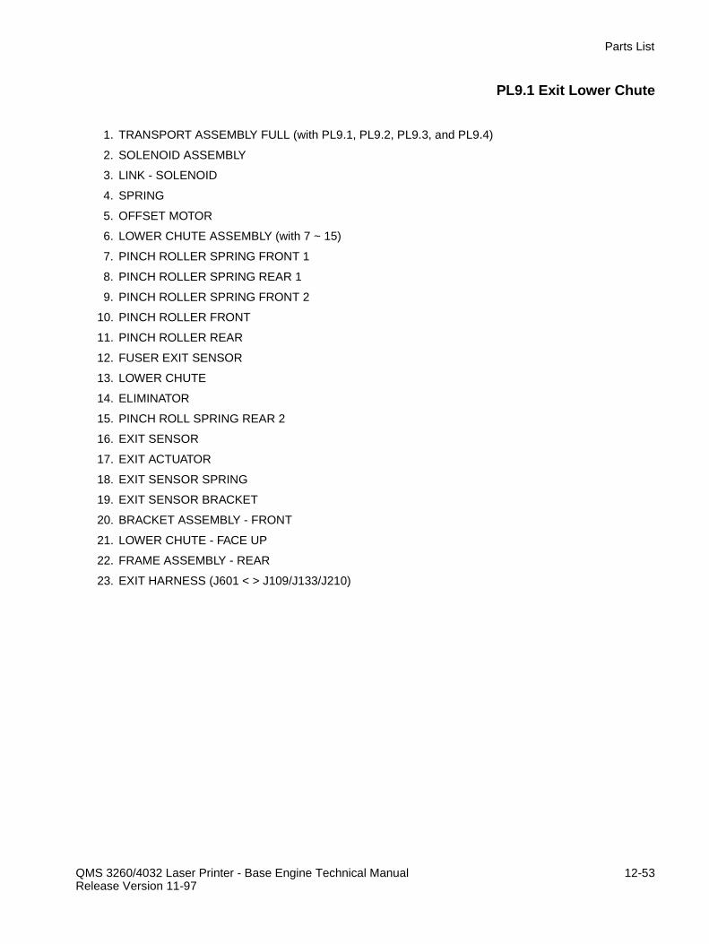
PL9.1 Exit Lower Chute
SER526XE
-52 QMS 3260/4032 Laser Printer - Base Engine Technical Manual Release Version 11-97
QMRe
Parts List
PL9.1 Exit Lower Chute
1. TRANSPORT ASSEMBLY FULL (with PL9.1, PL9.2, PL9.3, and PL9.4)
2. SOLENOID ASSEMBLY
3. LINK - SOLENOID
4. SPRING
5. OFFSET MOTOR
6. LOWER CHUTE ASSEMBLY (with 7 ~ 15)
7. PINCH ROLLER SPRING FRONT 1
8. PINCH ROLLER SPRING REAR 1
9. PINCH ROLLER SPRING FRONT 2
10. PINCH ROLLER FRONT
11. PINCH ROLLER REAR
12. FUSER EXIT SENSOR
13. LOWER CHUTE
14. ELIMINATOR
15. PINCH ROLL SPRING REAR 2
16. EXIT SENSOR
17. EXIT ACTUATOR
18. EXIT SENSOR SPRING
19. EXIT SENSOR BRACKET
20. BRACKET ASSEMBLY - FRONT
21. LOWER CHUTE - FACE UP
22. FRAME ASSEMBLY - REAR
23. EXIT HARNESS (J601 < > J109/J133/J210)
S 3260/4032 Laser Printer - Base Engine Technical Manual 12-53lease Version 11-97
12
Parts List
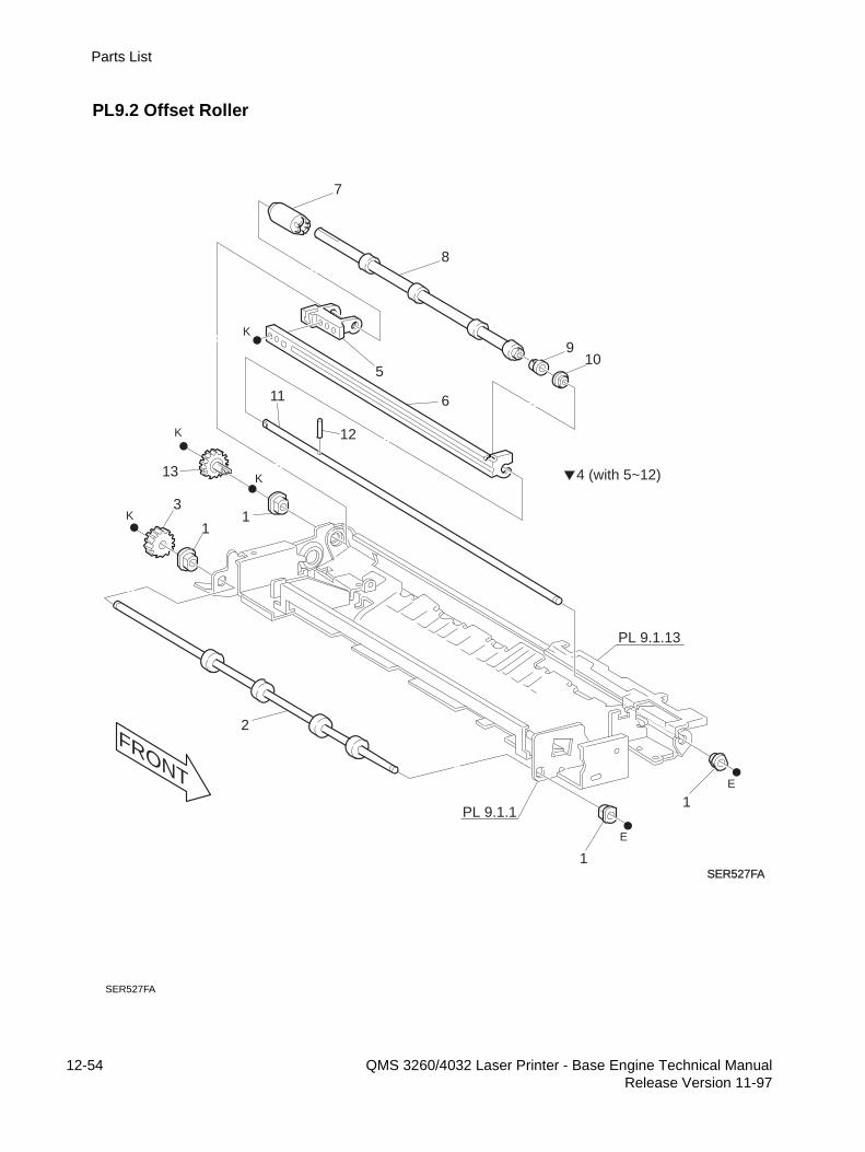
PL9.2 Offset Roller
SER527FA
SER527FA
4 (with 5~12)
FRONT
11
1
1
2
3
5
6
7
8
910
11
12
13
E
E
PL 9.1.1
PL 9.1.13
K
K
K
K
-54 QMS 3260/4032 Laser Printer - Base Engine Technical Manual Release Version 11-97

QMRe
Parts List
PL9.2 Offset Roller
1. BEARING
2. ROLLER ASSEMBLY - EXIT FUT
3. GEAR - 19 ASSEMBLY
4. OFFSET ROLLER ASSEMBLY (with 5 ~ 12)
5. OFFSET RACK
6. OFFSET BRACKET
7. OFFSET ROLLER SLEEVE
8. OFFSET ROLLER
9. OFFSET ROLLER BEARING REAR
10. OFFSET ROLLER BEARING FRONT
11. OFFSET SHAFT
12. OFFSET SHAFT PIN
13. GEAR - 19
S 3260/4032 Laser Printer - Base Engine Technical Manual 12-55lease Version 11-97

12
Parts List
PL9.3 Exit Upper Chute Assembly
SER528FB
SER528FBSER528FB
1 (with 2~16)
23
4
4
5
6
7
8
9
15
16
11
12
10
13
14
PL9.1.21PL9.1.22
PL9.1.20
s s s
s
s
s
s
FRONT
(J133)
PL9.1.23
-56 QMS 3260/4032 Laser Printer - Base Engine Technical Manual Release Version 11-97
QMRe
Parts List
PL9.3 Exit Upper Chute Assembly
1. CHUTE ASSEMBLY - UPPER (with 2 ~ 16)
2. SWITCH ASSEMBLY
3. PLATE - TIE
4. SPRING PLATE
5. SPRING ASSEMBLY - PINCH, H
6. SPRING ASSEMBLY - PINCH, I
7. PINCH ROLLER, FRONT
8. PINCH ROLLER, REAR
9. EXIT UPPER CHUTE
10. GUIDE PAPER
11. GUIDE PAPER
12. EXIT MIDDLE CHUTE
13. EXIT GATE
14. EXIT GATE SPRING
15. SPRING ASSEMBLY - PINCH, J
16. SPRING ASSEMBLY - PINCH, K
S 3260/4032 Laser Printer - Base Engine Technical Manual 12-57lease Version 11-97
12
Parts List
PL9.4 Exit Drive Assembly
SER529XE
-58 QMS 3260/4032 Laser Printer - Base Engine Technical Manual Release Version 11-97
QMRe
Parts List
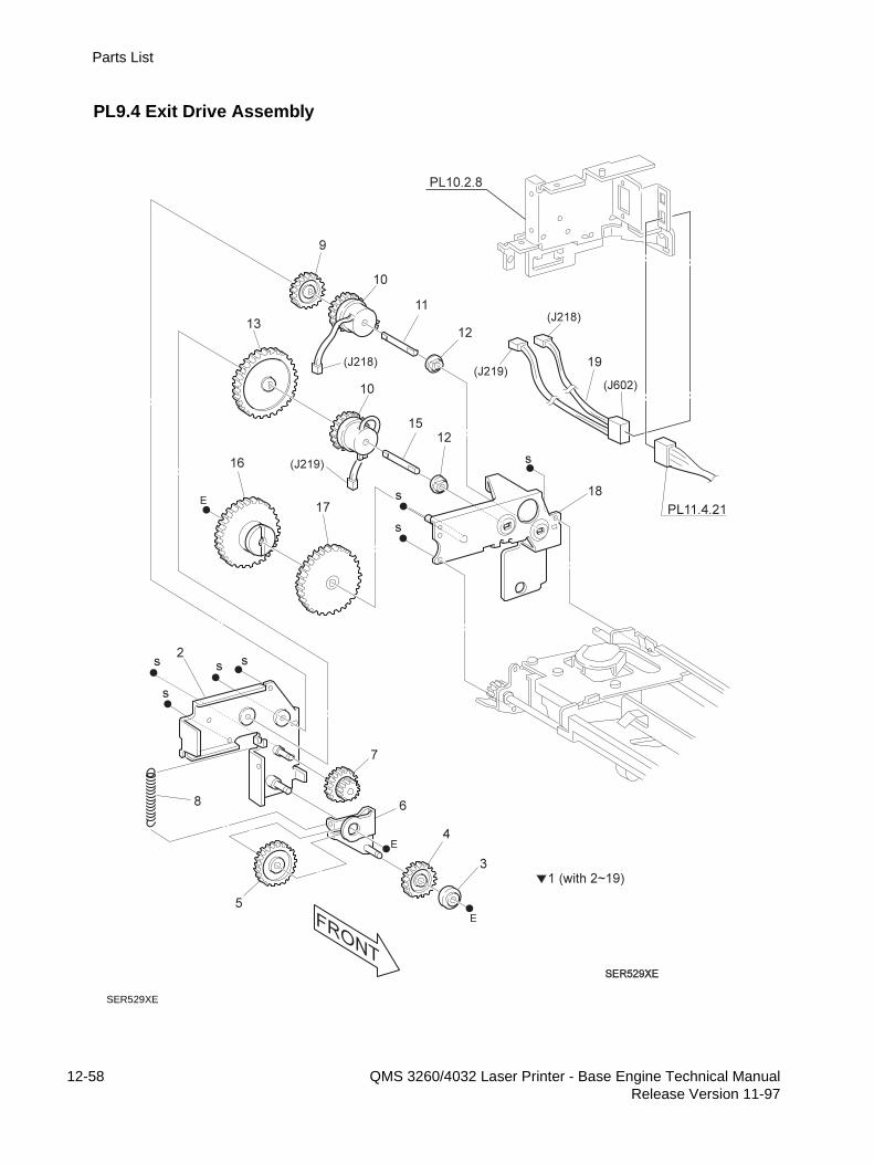
PL9.4 Exit Drive Assembly
1. EXIT DRIVE ASSEMBLY (with 2 ~ 19)
2. EXIT DRIVE SUPPORT
3. EXIT DRIVE IDLER PULLEY
4. EXIT GEAR 1
5. EXIT GEAR 2
6. EXIT GEAR 2 BRACKET
7. EXIT IDLER GEAR
8. EXIT RATCHET SPRING
9. INVERTER CCW GEAR
10. INVERTER CLUTCH
11. INVERTER CCW SHAFT
12. BEARING
13. INVERTER CW GEAR
14. - -
15. INVERTER CW SHAFT
16. INVERTER EXIT GEAR REAR
17. INVERTER EXIT GEAR FRONT
18. INVERTER BRACKET
19. EXIT WIRE HARNESS (J602 < > J218/J219)
S 3260/4032 Laser Printer - Base Engine Technical Manual 12-59lease Version 11-97

12
Parts List
PL10.1 Main Drive Assembly
SER530FC
SER530FC
1
S
S
S
S
SS
(J205)
(P204)
(J460)
2
PL11.4.23
PL10.2.13
PL6.1.8
-60 QMS 3260/4032 Laser Printer - Base Engine Technical Manual Release Version 11-97
QMRe
Parts List
PL10.1 Main Drive Assembly
1. MAIN DRIVE ASSEMBLY
2. HARNESS CLAMP
S 3260/4032 Laser Printer - Base Engine Technical Manual 12-61lease Version 11-97
12
Parts List
PL10.2 Fuser Drive Assembly
SER531FE
SER531FE
2
3
4
5
6
7
8
9
1011
1213
S
SS
S
S
E
1 (with 2~9)
(J23)(J600) (P12)
(FB)
(P104)
(P602)15
14
PL11.4.21
-62 QMS 3260/4032 Laser Printer - Base Engine Technical Manual Release Version 11-97
QMRe
Parts List
PL10.2 Fuser Drive Assembly
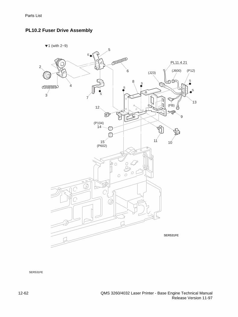
1. FRAME ASSEMBLY EXIT REAR (with 2 ~ 9)
2. GEAR 22T
3. SPRING
4. BRACKET ASSEMBLY
5. BRACKET
6. SPRING - EXIT
7. BRACKET
8. FRAME ASSEMBLY - EXIT, REAR
9. STOPPER HOOK
10. HARNESS CLAMP 1
11. HARNESS CLAMP 2
12. HARNESS CLAMP 3
13. DRAWER CONNECTOR (P12 < > J23/J600)
14. CONNECTOR P104
15. CONNECTOR P602
S 3260/4032 Laser Printer - Base Engine Technical Manual 12-63lease Version 11-97

12
Parts List
PL11.1 Power Inlet and LVPS
SER532FC
SER532FC
12
3
4
4
5
5
6
7
8
11
S
S
S
S
SS
S
S
S
S
S
S
S
S
SPL11.2.21
9
10
(J1)
(F51~54)
(J501)
(J420)
(J400)
(J502)
(J20)
(J19)
(J13)
(J235)
(J401)
(F56)
(P499)
(P478)
(F55)
S
PL11.4.12
PL11.4.12
-64 QMS 3260/4032 Laser Printer - Base Engine Technical Manual Release Version 11-97

QMRe
Parts List
PL11.1 Power Inlet and LVPS
1. POWER INLET CONNECTOR
2. NOISE FILTER PWB 120
- NOISE FILTER PWB 220
3. BRACKET - N/F
4. PWB STUD
5. HARNESS CLAMP
6. MAIN POWER HARNESS (F51~F54 / J1 < > J13/J19/J20)
7. MAIN SWITCH
8. BRACKET ASSEMBLY SWITCH
9. OUTLET
10. BRACKET FINISHER
11. PS ASSEMBLY -M4 120V
- PS ASSEMBLY -M4 220V
S 3260/4032 Laser Printer - Base Engine Technical Manual 12-65lease Version 11-97

12
Parts List
PL11.2 HVPS and MCU PWB
SER533FF
-66 QMS 3260/4032 Laser Printer - Base Engine Technical Manual Release Version 11-97

QMRe
Parts List
PL11.2 HVPS and MCU PWB
1. AC DRIVER PWB 120
- AC DRIVER PWB 220
2. - -
3. - -
4. HVPS
5. MCU ASSEMBLY (with 6 ~ 8)
6. MCU PWB
7. BRACKET MCU
8. COVER MCU
9. - -
10. LEFT COVER INTERLOCK SWITCH
11. INTERLOCK SWITCH BRACKET
12. INTERLOCK SWITCH LEVER
13. SUPPORT HARNESS
14. HARNESS CHANNEL
15. - -
16. - -
17. HARNESS CLAMP 2
18. PWB SUPPORT
19. HARNESS CLAMP 4
20. BRACKET AC - DRIVE
21. AC DRIVE HARNESS (J478 < > P499)
22. HCF CONNECTOR
23. DUPLEX UNIT CONNECTOR
24. MAIL BOX CONNECTOR
25. OPTION CONNECTOR BRACKET
26. HARNESS - ASSEMBLY, EXIT
27. TRANSFORMER 220V
S 3260/4032 Laser Printer - Base Engine Technical Manual 12-67lease Version 11-97

12
Parts List
PL11.3 ESS Assembly
SER534FE
2
3
4
55
6
89
12
12
1212
13
14
16
S
S S
SS
S
S
S
S
S
SS
S
S
S S
S
S
SS
S
S
S SS
S
S
S
S
S
S
S
S
S
S
S
SER534FE
A
A
B
B
FRONT
1 (with 2~9,12)
11
10
7
(J422)
(J424)
(J421)
(J402)
(J417)
(J420)
(J501)(J400)
(J502)
S
S
SS
S
15
(P416)
(P430)
PL11.4.12
PL11.4.12
18
17
C
SC
(J423)
(P423)
-68 QMS 3260/4032 Laser Printer - Base Engine Technical Manual Release Version 11-97

QMRe
Parts List
PL11.3 ESS Assembly
1. ESS ASSEMBLY - (with 2 ~ 9, and 12)
2. BRACKET ASSEMBLY - PWB MOTHER
3. ESS MOTHER PWB
4. BUSH SADDLE
5. GUIDE
6. FAN ASSEMBLY
7. BRACKET - FAN
8. BOX ASSEMBLY - ESS
9. PANEL - REAR
10. COVER - ESS
11. COVER - SIMM
12. CLAMP (4)
13. QMS Video Controller
14. ESS DRAWER PANEL
15. HARNESS ASSEMBLY ROS V (P416 < > P430)
16. HARNESS ASSEMBLY CONSOLE
17. CORE
18. CLAMP+
S 3260/4032 Laser Printer - Base Engine Technical Manual 12-69lease Version 11-97

12
Parts List
PL11.4 Harness
SER564FC
(J457)
(P457)
(P456)
(P460)(P458)
(P459)(P403)
(P405)
(P404)(P406)(P408)(P402)
(P454)
(P127)
(P462)
(P461)
(P400)
(P401)
(P410)
(P500) (J500)
(J460)
(P204)
(J205)(J454)
(J458)
(J461)
(J459)
(J405)
(J404)(J140)
(J401)(P234)
(J400)
(J478)
(J462)
(P201)
(P202)
(P600)
(P200)(P104)
(P602)
(P601)
(P209)
(J477)
(J499)
(J207)
(J407)
(J502)
(J501)
(J106)
(J420)
(J422)
(P235)(J456)
(J402)
(J141)(J142)
(P607)
(P240)(J241)
(J408)
(J403)(J406)
(J613A)(J613B)(J613C)(J613D)
(J603)
(J203)
(J101)
(J612A)
(J611A)
(J612B)
(J611B)
(J103)
(J100)(J102)
(J105)
(J232)(J233)
(J606)
(F5231)
(F5230)
SER564FC
s
s
s
12
13
14
15
16
17
18
19
20
21
23
24
PL7.2.17
(FB)
(CB)
s
s
(DTS)
(BTR)
-70 QMS 3260/4032 Laser Printer - Base Engine Technical Manual Release Version 11-97

QMRe
Parts List
PL11.4 Harness
1. - -
2. - -
3. - -
4. - -
5. - -
6. - -
7. - -
8. - -
9. - -
10. - -
11. - -
12. HARNESS ASSEMBLY - DC MAIN (LVPS: J400/J420< >J501/J502, FUSER; J401< >J477/P235, ESSMOTOR; J402< >J422, ROS; J456< >J106/J207/P234/J407, TEST; J478< >P499)
13. HARNESS ASSEMBLY - OEM 1TM REAR (J408< >J140/J141/J142/P607/P240/J241)
14. HARNESS ASSEMBLY - I/F, TRAY (J406< >J613A/B/C/D)
15. HARNESS ASSEMBLY - BOTTOM (J403< > J101/J203/J603)
16. HARNESS ASSEMBLY - I/F, DUPLEX (J404< >J611A/B)
17. HARNESS ASSEMBLY - I/F, OUTPUT (J405< >J612A/B)
18. HARNESS ASSEMBLY - REGISTRATION SENSOR (J459< >J100/J102/J103)
19. HARNESS ASSEMBLY - SIZE, EXIT (J461< >J105)
20. HARNESS ASSEMBLY - INTERLOCK SWITCH (J458< >J232/J233/F5230/F5231)
21. HARNESS ASSEMBLY - DC REAR, EXIT (J462< >P104/P200/P201/P202/P209/P600/P601/P602)
22. - -
23. HARNESS ASSEMBLY - MAIN MOTOR (J460< >P204/J205)
24. HARNESS ASSEMBLY - HVPS (J457< >J500)
S 3260/4032 Laser Printer - Base Engine Technical Manual 12-71lease Version 11-97

12
Parts List
Blank Page
-72 QMS 3260/4032 Laser Printer - Base Engine Technical Manual Release Version 11-97
QMS 3260/4032 Laser Printer
Technical Reference Section
13. Principles of Operation . . . . . . . . . . . . . . . . . . . . . . . . . . . . . . . . . . . . . . . . . 13-1
14. Wiring Diagrams and Signal Information . . . . . . . . . . . . . . . . . . . . . . . . 14-1
15. Printer Specifications . . . . . . . . . . . . . . . . . . . . . . . . . . . . . . . . . . . . . . . . . . . 15-1
16. Glossary of Terms, Acronyms, and Abbreviations . . . . . . . . . . . . . . . 16-1

Blank Page

QMRe
Principles of Operation
Section 13 - Principles of Operation Contents
1- Printer Power . . . . . . . . . . . . . . . . . . . . . . . . . . . . . . . . . . . . . . . . . . . . . . . . . . . . . . . . . . . . . . . . . . . 13-32- Printer Control. . . . . . . . . . . . . . . . . . . . . . . . . . . . . . . . . . . . . . . . . . . . . . . . . . . . . . . . . . . . . . . . . . . 13-6
QMS 3260/4032 Error Code Table. . . . . . . . . . . . . . . . . . . . . . . . . . . . . . . . . . . . . . . . . . . . . . . . . . 13-173- Mechanical Drive . . . . . . . . . . . . . . . . . . . . . . . . . . . . . . . . . . . . . . . . . . . . . . . . . . . . . . . . . . . . . . . 13-374- The Paper Path . . . . . . . . . . . . . . . . . . . . . . . . . . . . . . . . . . . . . . . . . . . . . . . . . . . . . . . . . . . . . . . . . 13-425- The ROS . . . . . . . . . . . . . . . . . . . . . . . . . . . . . . . . . . . . . . . . . . . . . . . . . . . . . . . . . . . . . . . . . . . . . . 13-556- Xerographics. . . . . . . . . . . . . . . . . . . . . . . . . . . . . . . . . . . . . . . . . . . . . . . . . . . . . . . . . . . . . . . . . . . 13-617- Fusing . . . . . . . . . . . . . . . . . . . . . . . . . . . . . . . . . . . . . . . . . . . . . . . . . . . . . . . . . . . . . . . . . . . . . . . . 13-74
S 3260/4032 Laser Printer - Base Engine Technical Manual 13-1lease Version 11-97

13
Principles of Operation
Blank Page
-2 QMS 3260/4032 Laser Printer - Base Engine Technical Manual Release Version 11-97

QMRe
Principles of Operation
1- Printer PowerThe power supplies in QMS 3260/4032 provide the voltages that the printer requires to operate. The vari-ous printer functions require 110VAC, +5VDC, +24VDC, and several high voltage DC and AC values thatare used by xerographics.
The printer AC power cord plugs into a grounded AC wall outlet. The cord carries AC line voltage to theNoise Filter PWB . The Noise Filter smooths the AC voltage and sends it to the Main Power Switch.Switching on the Main Power Switch applies AC voltage to the AC Driver PWB and to the Low VoltagePower Supply (LVPS) PWB.
The AC Driver PWB is the interface between printer control (MCU) and the Fuser. Fuser sensors con-nected to the AC Driver PWB send Fuser status information to the Driver PWB, which the PWB routes tothe MCU PWB. The MCU processes the information and sends commands back to the AC Driver PWB totell the AC Driver whether or not to switch on the Fuser Heat Rods.
The Low Voltage Power Supply PWB , or LVPS, converts the 110VAC to regulated +24VDC and +5VDCvoltages. The LVPS sends these voltages to the MCU PWB. The MCU uses the voltages for internal pro-cessing and for printer component operation. The MCU also sends +24VDC to the High Voltage PowerSupply PWB.
The High Voltage Power Supply PWB , or HVPS, converts the +24VDC received from the MCU PWB tothe high voltages that are required by the xerographic system of the printer. The HVPS produces theCharge (CR), Transfer (TR), Developer Bias (DB), and Detack (DTS) voltages, and sends them on to theEP Cartridge and to the Bias Transfer Roll (BTR).
SR1301XA
S 3260/4032 Laser Printer - Base Engine Technical Manual 13-3lease Version 11-97
13
Principles of Operation
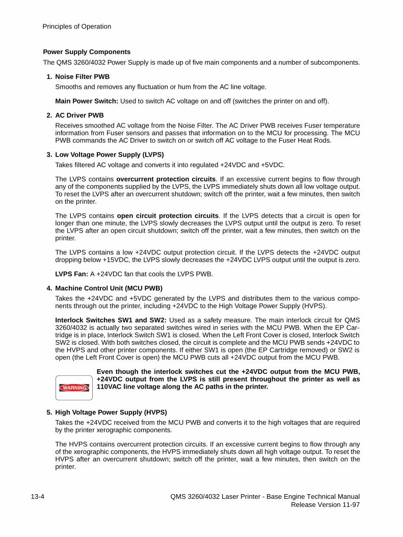
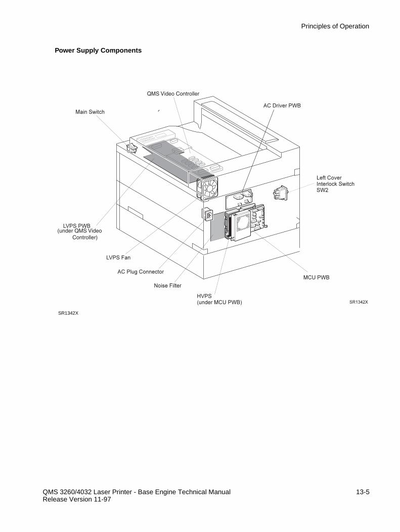
Power Supply Components
The QMS 3260/4032 Power Supply is made up of five main components and a number of subcomponents.
1. Noise Filter PWB
Smooths and removes any fluctuation or hum from the AC line voltage.
Main Power Switch: Used to switch AC voltage on and off (switches the printer on and off).
2. AC Driver PWB
Receives smoothed AC voltage from the Noise Filter. The AC Driver PWB receives Fuser temperatureinformation from Fuser sensors and passes that information on to the MCU for processing. The MCUPWB commands the AC Driver to switch on or switch off AC voltage to the Fuser Heat Rods.
3. Low Voltage Power Supply (LVPS)
Takes filtered AC voltage and converts it into regulated +24VDC and +5VDC.
The LVPS contains overcurrent protection circuits . If an excessive current begins to flow throughany of the components supplied by the LVPS, the LVPS immediately shuts down all low voltage output.To reset the LVPS after an overcurrent shutdown; switch off the printer, wait a few minutes, then switchon the printer.
The LVPS contains open circuit protection circuits . If the LVPS detects that a circuit is open forlonger than one minute, the LVPS slowly decreases the LVPS output until the output is zero. To resetthe LVPS after an open circuit shutdown; switch off the printer, wait a few minutes, then switch on theprinter.
The LVPS contains a low +24VDC output protection circuit. If the LVPS detects the +24VDC outputdropping below +15VDC, the LVPS slowly decreases the +24VDC LVPS output until the output is zero.
LVPS Fan: A +24VDC fan that cools the LVPS PWB.
4. Machine Control Unit (MCU PWB)
Takes the +24VDC and +5VDC generated by the LVPS and distributes them to the various compo-nents through out the printer, including +24VDC to the High Voltage Power Supply (HVPS).
Interlock Switches SW1 and SW2: Used as a safety measure. The main interlock circuit for QMS3260/4032 is actually two separated switches wired in series with the MCU PWB. When the EP Car-tridge is in place, Interlock Switch SW1 is closed. When the Left Front Cover is closed, Interlock SwitchSW2 is closed. With both switches closed, the circuit is complete and the MCU PWB sends +24VDC tothe HVPS and other printer components. If either SW1 is open (the EP Cartridge removed) or SW2 isopen (the Left Front Cover is open) the MCU PWB cuts all +24VDC output from the MCU PWB.
Even though the interlock switches cut the +24VDC output from the MCU PWB,+24VDC output from the LVPS is still present throughout the printer as well as110VAC line voltage along the AC paths in the printer.
5. High Voltage Power Supply (HVPS)
Takes the +24VDC received from the MCU PWB and converts it to the high voltages that are requiredby the printer xerographic components.
The HVPS contains overcurrent protection circuits. If an excessive current begins to flow through anyof the xerographic components, the HVPS immediately shuts down all high voltage output. To reset theHVPS after an overcurrent shutdown; switch off the printer, wait a few minutes, then switch on theprinter.
-4 QMS 3260/4032 Laser Printer - Base Engine Technical Manual Release Version 11-97
QMRe
Principles of Operation
Power Supply Components
SR1342X
S 3260/4032 Laser Printer - Base Engine Technical Manual 13-5lease Version 11-97

13
Principles of Operation
2- Printer ControlPrinter Control is a broad term that is used to describe the printer resources that monitor and control theactions and operations of the QMS 3260/4032 printer; from warm-up, through the print cycle, to machineerror detection.
The center of printer control for the QMS 3260/4032 base engine is the Machine Control Unit PWB, orMCU PWB. The MCU contains an 8 bit microcomputer. The MCU contains ASICs (Application SpecificIntegrated Circuits) for image data transfer and communication control, ROM, RAM, a 16 bit integratedtimer, programmable timing pattern control, a watch dog timer, serial communications interfaces, an A/Dconverter, a D/A converter, I/O ports, and a DMA controller.
The MCU PWB provides the logic and information processing that is necessary for the printer to function.Every electrical component within the printer is connected either directly or indirectly to the MCU PWB.Sensors in the printer send printer status information to the MCU. The MCU processes that informationand compares it to timing tables that are stored in onboard ROM. Acting on the results of the processing,the MCU sends commands to various printer components; switching on motors, switching off voltages, sig-naling statuses. Non-Volatile RAM on the MCU PWB stores adjustable operation parameters, such asFuser temperature and laser strength, that are used as reference during printer operation.
The ESS Mother PWB is connected to the MCU PWB. The QMS Video Controller is connected to the ESSMother PWB, so the QMS Video Controller is indirectly connected to the MCU PWB. Video data travelsfrom the QMS Video Controller, through the ESS Mother PWB to the Laser Diode PWB.
SR1343X
-6 QMS 3260/4032 Laser Printer - Base Engine Technical Manual Release Version 11-97

QMRe
Principles of Operation
QMS 3260/4032 Printer Control
SR1310XA
S 3260/4032 Laser Printer - Base Engine Technical Manual 13-7lease Version 11-97

13
Principles of Operation
Printer Control Components
The QMS 3260/4032 Printer Control is make up of the MCU PWB and numerous connected components.
Machine Control Unit PWB (MCU PWB)
Receives status and command information from sensors and from the QMS Video Controller. Controlsmost printer operations. The MCU PWB performs nine major functions:
1- Communicates with the Printer Controller (ESS).2- Maintains the system clock.3- Controls the printing process.4- Controls the ROS, the Fuser, and the drive assemblies.5- Distributes +5VDC and +24VDC to various printer components.6- Monitors printer status.7- Maintains a running print count.8- Maintains NVRAM settings.9- Controls printer options.
Components attached to or associated with the MCU PWB:
1. Low Voltage Power Supply
Converts 110VAC to +5VDC and +24VDC.
2. QMS Video Controller
Connected to the MCU PWB through the ESS Mother PWB. The interface between the print engineand the host computer. The ESS processes the raw video data sent by the host computer.
3. ESS Mother PWB
Connected to the QMS Video Controller, to the MCU PWB, and to the Control Panel. The ESS MotherPWB receives video data from the QMS Video Controller and sends it on to the ROS Laser Diode.
4. Control Panel
Connected to the ESS Mother PWB, the Control Panel displays status information send from the MCUPWB and QMS Video Controller.
5. AC Driver PWB
Switches 110VAC to the two Fuser Heat Rods. Fuser temperature sensors are connected to the ACDrive PWB. The AC Drive PWB sends the temperature information to the MCU PWB.
6. High Voltage Power Supply
Converts +24VDC received from the MCU PWB to several high voltages that are required by printerxerographics.
7. Toner Sensor
Magnetic sensor that monitors the CRU toner level.
8. CRU
Drum usage information that is stored in the CRU.
9. ROS
The SOS (Start of Scan) Sensor, the ROS Motor, and the Laser Diode.
10. Main Motor
Provides most of the mechanical drive for the printer.
-8 QMS 3260/4032 Laser Printer - Base Engine Technical Manual Release Version 11-97
QMRe
Principles of Operation
11. Fuser Fan
Cools the Fuser area.
12. Feed Clutch
Transmits Main Motor drive to the Tray 1 Feed Rolls.
13. Registration Gate Clutch
Transmits Main Motor drive to the Registration Rolls.
14. Fuser Exit Sensor
Monitors paper travel out of the Fuser.
15. Face Up Exit Sensor
Monitors paper travel out of the Offset Unit.
16. Full Stack Sensor
Monitors the paper level in the Output Tray.
17. Exit Gate Solenoid
Toggles the Exit Gate.
18. Inverter CW Clutch
Transmits Main Motor drive, forward, to the Offset Rolls.
19. Inverter CCW Clutch
Transmits Main Motor drive, reverse, to the Offset Rolls.
20. Offset Motor
Provides mechanical drive for the Offset Unit.
21. Duplex Module PWB
Provides +5VDC, +24VDC, and command and status lines to the Duplex PWB option.
22. Mailbox
Provides +5VDC, +24VDC, and command and status lines to the Mailbox option.
23. Finisher
Provides +5VDC, +24VDC, and command and status lines to the Finisher option.
24. Envelope Feeder
Provides +5VDC, +24VDC, and command and status lines to the Envelope Feeder option.
25. Cabinet Drive PWB
Provides +5VDC, +24VDC, and command and status lines to the High Capacity Feeder option.
S 3260/4032 Laser Printer - Base Engine Technical Manual 13-9lease Version 11-97

13
Principles of Operation
26. Size Sensor 1
Monitors the size of the paper that is loaded in Feeder 1. The Actuator Assembly located at the rear ofthe Paper Tray has series of cams that face the Size Sensor PWB. Pushing the Paper Guide againstthe paper stack slides the Actuator Assembly along a track. When the Tray is inserted into the Feeder,the cams on the Actuator press the switches on the Size Sensor PWB in a pattern that is unique to theposition of the Paper Guide. The MCU PWB interprets this pattern as a specific paper size.
27. Registration Sensor
Monitors paper travel out of the paper tray.
28. No Paper Sensor 1
Monitors the paper level in Feeder 1. When the Lift Motor raise the Bottom Plate, the Plate raises thepaper stack, the stack pushes the No Paper Actuator up and away from the No Paper Sensor. TheSensor sends a paper present signal to the MCU PWB. When the last sheet of paper is fed out of thePaper Tray, the No Paper Actuator drops through a cutout in the Bottom Plate. The Actuator thenblocks the Sensor, and the Sensor sends a no paper signal to the MCU PWB.
SER717F
SR1493X
-10 QMS 3260/4032 Laser Printer - Base Engine Technical Manual Release Version 11-97
QMRe
Principles of Operation
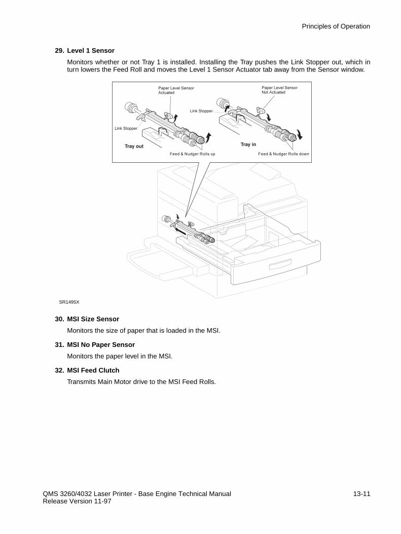
29. Level 1 Sensor
Monitors whether or not Tray 1 is installed. Installing the Tray pushes the Link Stopper out, which inturn lowers the Feed Roll and moves the Level 1 Sensor Actuator tab away from the Sensor window.
30. MSI Size Sensor
Monitors the size of paper that is loaded in the MSI.
31. MSI No Paper Sensor
Monitors the paper level in the MSI.
32. MSI Feed Clutch
Transmits Main Motor drive to the MSI Feed Rolls.
SR1495X
S 3260/4032 Laser Printer - Base Engine Technical Manual 13-11lease Version 11-97

13
Principles of Operation
33. Lift Up Motor 1
Raises the paper tray in Feeder 1. The MCU PWB switches on the Lift Motor. The Motor rotates asquare, metal shaft that is located inside the Paper Tray. The Shaft raises the Tongue, which in turnraises the Bottom Plate, and the paper stack, up to the Feed Rolls.
34. Take Away Roll Sensor
Monitors the paper travel at the Take Away Roll.
35. Interlock Switches 1 and 2
Monitors the CRU position Switch 1 and Left Cover Interlock Switch 2 on Feeder 1.
36. Feed Clutch 2
Transmits Main Motor drive to the Tray 2 Feed Rolls.
37. No Paper Sensor 2
Monitors the paper level in Feeder 2. Functions identical to No Paper Sensor 1.
38. Level 2 Sensor
Monitors whether or not Tray 2 is installed.
39. Size Sensor 2
Monitors the size of the paper that is loaded in Feeder 2.
40. Take Away Roll Sensor 2
Monitors the paper travel at the Take Away Roll 2.
41. Lift Up Motor 2
Raises the paper tray in Feeder 2.
42. Left Cover Interlock 2
Monitors the Left Cover Interlock Switch on Feeder 2.
SR1494X
-12 QMS 3260/4032 Laser Printer - Base Engine Technical Manual Release Version 11-97

QMRe
Principles of Operation
Function of the MCU during printer control
1. Input from sensors
Sensors tell the MCU what is going on within the printer and what is happening to the sheet of paperduring a print cycle.
Example below:Printer sensors send their status to the MCU PWB. The sensor status signals tell the MCU whetherthey are actuated or not actuated (on or off, high or low). If measured with a voltmeter, some sensorsignals to the MCU would be +5VDC when on and 0VDC when off, while other sensors may be 0VDCwhen on and +5VDC when off. This high/low decision is determined when the printer is designed.
SR1311X
S 3260/4032 Laser Printer - Base Engine Technical Manual 13-13lease Version 11-97

13
Principles of Operation
2. Processing input information
Logic on the MCU compares the input information with the timing and reference values that are storedin ROM and NVRAM on the PWB.
Example below:The Fuser Thermistor monitors the temperature of the Fuser Heat Roll and sends the current temper-ature value to the AC Drive PWB. The AC Drive PWB relays the temperature data to the MCU PWB.The MCU compares the current temperature with the set (or expected) temperature that is stored inNVRAM on the MCU PWB. If the current temperature is lower than the set temperature, the MCUsends a signal to the AC Drive PWB to switch on the Fuser Heat Rod until the current temperaturereaches the set temperature.
SR1312X
-14 QMS 3260/4032 Laser Printer - Base Engine Technical Manual Release Version 11-97

QMRe
Principles of Operation
3. Output to motors, solenoids, and other components.
After comparing input values with timing and reference values, the MCU makes a decision on the cur-rent status of the printer, and responds appropriately. The MCU may switch on or off motors, solenoids,or other components. The MCU may also signal that an error occurred. (There is a table of QMS 3260/4032 Error Codes located at the end of this section 2 - Printer Control).
Example below:A the start of a print cycle, the MCU switches on the Main Drive Motor, and then the Feed Clutch. TheMCU uses the Feed Clutch actuation as a timing marker. The Feed Rolls attached to the Feed Clutchdrive a sheet of paper out of the paper tray and down the paper path. As the sheet of paper travelsdown the paper path it strikes the Registration Sensor. The Sensor sends a signal to the MCU PWBtelling it that the paper has arrived. The MCU takes the elapsed time from when it actuated the FeedClutch to the time it received the signal from the Registration Sensor and compares that time with theset time (or expected time) that is stored in ROM on the MCU PWB. If the time elapsed is within range,the print cycle continues. If the time elapsed is slower than the set time or if there was no signal fromthe Registration Sensor within the set time, the MCU interprets that as an error and sends an E1-1Misfeed Jam status to the QMS Video Controller.
SR1313X
S 3260/4032 Laser Printer - Base Engine Technical Manual 13-15lease Version 11-97

13
Principles of Operation
4. Processing image data
Although the MCU PWB does control and monitor the operation of the ROS, the actual video data sentby a host computer bypasses the MCU PWB on its way to the Laser Diode PWB.
Example below:Video data originating from either a local computer or a network computer enters the printer throughthe ports in the QMS Video Controller. The QMS Video Controller stores and buffers the raw data andthen converts it to rasterized data that controls the Laser Diode. The rasterized data leaves the QMSVideo Controller and enters the ESS Mother PWB. The ESS Mother PWB is an interface for the data.The ESS Mother PWB does not buffer nor process the data, it simply passes it along as a video sig-nal to the Laser Diode PWB. The video signal switches the Laser Diode on and off according to theimage information sent in the raw data.
SR1344X
-16 QMS 3260/4032 Laser Printer - Base Engine Technical Manual Release Version 11-97

QMRe
Principles of Operation
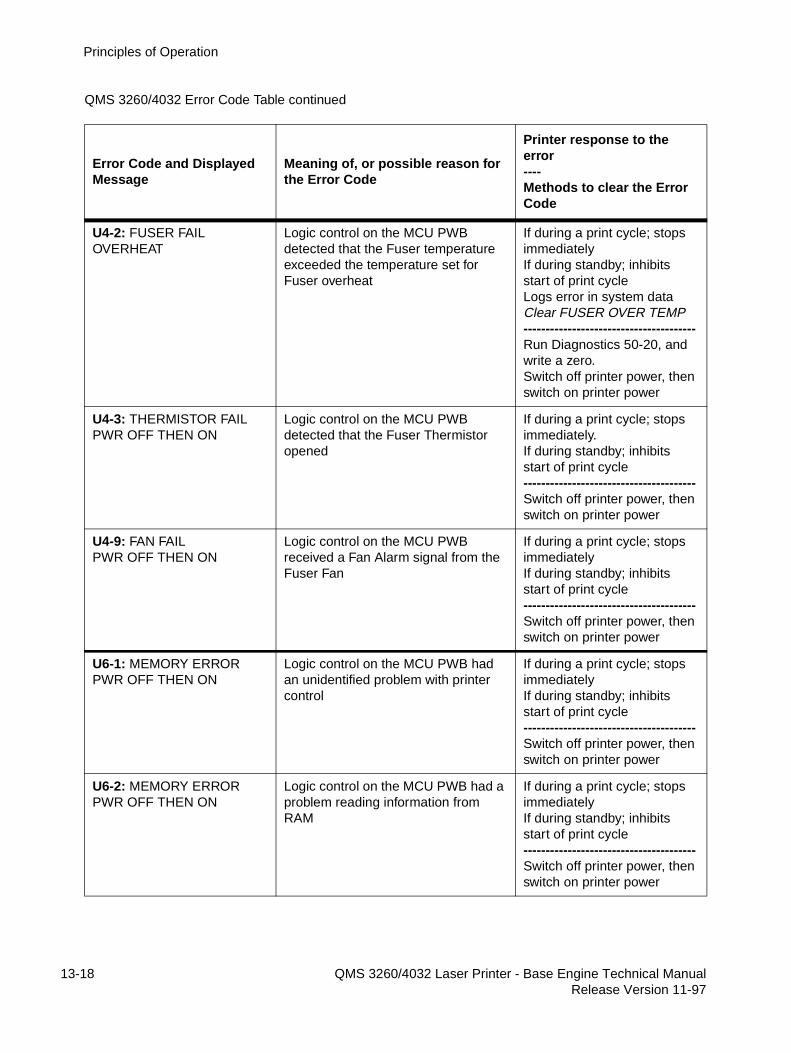
QMS 3260/4032 Error Code TableThis table lists all of the printer Error Codes that the QMS 3260/4032 MCU can generate. The Error Codesare listed by displayed priority, starting with the highest priority code. If multiple errors should occur, theprinter displays the code with the highest priority. Actual messages displayed on the printer Control Panelmay vary somewhat from the text shown in the Display Message column.
Error Code and Displayed Message
Meaning of, or possible reason for the Error Code
Printer response to the error---------------------------------------Methods to clear the Error Code
U1-1: MAIN MOTOR FAILPWR OFF THEN ON
Logic control on the MCU PWB detected a problem with the Main Motor
Stops immediately---------------------------------------Switch off printer power, then switch on printer power
U1-3: LVPS FAN FAILPWR OFF THEN ON
Logic control on the MCU PWB detected a problem with the LVPS Fan
Stops immediately---------------------------------------Switch off printer power, then switch on printer power
U3-1: ROS FAILPWR OFF THEN ON
Logic control on the MCU PWB received a constant HIGH signal from the SOS Sensor
Stops immediately---------------------------------------Switch off printer power, then switch on printer power
U3-3: LD CONTROL FAILPWR OFF THEN ON
Logic control on the MCU PWB detected that the time between sig-nals from the SOS Sensor was longer than specified
Stops immediately---------------------------------------Switch off printer power, then switch on printer power
U3-4: LD CONTROL FAIL Logic control on the MCU PWB detected that the time between sig-nals from the SOS Sensor was shorter than specified
Stops immediately---------------------------------------Switch off printer power, then switch on printer power
U3-5: ROS MOTOR FAILPWR OFF THEN ON
Logic control on the MCU PWB detected that the ROS Motor has not come up to full speed within the spec-ified time
Stops immediately---------------------------------------Switch off printer power, then switch on printer power
U4-1: FUSER FAILPWR OFF THEN ON
Logic control on the MCU PWB detected that the Thermistor remained on for longer than specified
Stops immediately---------------------------------------Switch off printer power, then switch on printer power
S 3260/4032 Laser Printer - Base Engine Technical Manual 13-17lease Version 11-97
13
Principles of Operation
QMS 3260/4032 Error Code Table continued
Error Code and Displayed Message
Meaning of, or possible reason for the Error Code
Printer response to the error----Methods to clear the Error Code
U4-2: FUSER FAILOVERHEAT
Logic control on the MCU PWB detected that the Fuser temperature exceeded the temperature set for Fuser overheat
If during a print cycle; stops immediatelyIf during standby; inhibits start of print cycleLogs error in system data Clear FUSER OVER TEMP---------------------------------------Run Diagnostics 50-20, and write a zero.Switch off printer power, then switch on printer power
U4-3: THERMISTOR FAILPWR OFF THEN ON
Logic control on the MCU PWB detected that the Fuser Thermistor opened
If during a print cycle; stops immediately.If during standby; inhibits start of print cycle---------------------------------------Switch off printer power, then switch on printer power
U4-9: FAN FAILPWR OFF THEN ON
Logic control on the MCU PWB received a Fan Alarm signal from the Fuser Fan
If during a print cycle; stops immediatelyIf during standby; inhibits start of print cycle---------------------------------------Switch off printer power, then switch on printer power
U6-1: MEMORY ERRORPWR OFF THEN ON
Logic control on the MCU PWB had an unidentified problem with printer control
If during a print cycle; stops immediatelyIf during standby; inhibits start of print cycle---------------------------------------Switch off printer power, then switch on printer power
U6-2: MEMORY ERRORPWR OFF THEN ON
Logic control on the MCU PWB had a problem reading information from RAM
If during a print cycle; stops immediatelyIf during standby; inhibits start of print cycle---------------------------------------Switch off printer power, then switch on printer power
-18 QMS 3260/4032 Laser Printer - Base Engine Technical Manual Release Version 11-97

QMRe
Principles of Operation
QMS 3260/4032 Error Code Table continued
Error Code and Displayed Message
Meaning of, or possible reason for the Error Code
Printer response to the error----Methods to clear the Error Code
U6-3: MEMORY ERRORPWR OFF THEN ON
Logic control on the MCU PWB had an unidentified problem with NVRAM
If during a print cycle; stops immediatelyIf during standby; inhibits start of print cycle---------------------------------------Switch off printer power, then switch on printer power
U6-4: MEMORY ERRORPWR OFF THEN ON
Logic control on the MCU PWB had a problem reading information from NVRAM
If during a print cycle; stops immediatelyIf during standby; inhibits start of print cycle---------------------------------------Switch off printer power, then switch on printer power
E1-1: PAPER JAMREGISTRATION
Logic control on the MCU PWB sensed the Registration Sensor was not actuated within the specified time since the Feed Clutch was actuated
Stops immediately---------------------------------------Open Left Cover and remove jammed sheet of paper
E1-2: PAPER JAMREGISTRATION
Logic control on the MCU PWB sensed the Fuser Exit Switch was not actuated within the specified time since the Registration Clutch was actuated
Stops immediately---------------------------------------Open Left Cover, remove jammed sheet of paper, close Left Cover
E1-3: PAPER JAMREGISTRATION
Logic control on the MCU PWB sensed the Face Up Exit Sensor was not actuated within the specified time since the Fuser Exit Switch was actu-ated
Stops immediately---------------------------------------Open Left Cover, remove jammed sheet of paper, close Left Cover
E1-6: PAPER JAMREGISTRATION
Logic control on the MCU PWB sensed the Registration Sensor was on while the printer was in standby
Inhibits start of print cycle---------------------------------------Open Left Cover, remove jammed sheet of paper, close Left Cover
E3-1: PAPER JAMFUSER
Logic control on the MCU PWB sensed the Fuser Exit Switch did not deactuate within the specified time after the Switch actuated
Stops immediately---------------------------------------Open Left Cover, remove jammed sheet of paper, close Left Cover
S 3260/4032 Laser Printer - Base Engine Technical Manual 13-19lease Version 11-97

13
Principles of Operation
QMS 3260/4032 Error Code Table continued
Error Code and Displayed Message
Meaning of, or possible reason for the Error Code
Printer response to the error----Methods to clear the Error Code
E3-6: PAPER JAMFUSER
Logic control on the MCU PWB sensed the Fuser Exit Switch was on while the printer was in standby
Inhibits start of print cycle---------------------------------------Open Left Cover, remove jammed sheet of paper, close Left Cover
E4-1: PAPER JAMFACE UP EXIT
Logic control on the MCU PWB sensed that during the Face Down Mode, the Face Up Exit Sensor did not deactuate within the specified time after the Sensor actuated
Stops immediately---------------------------------------Open Left Cover, remove jammed sheet of paper, close Left Cover
E4-2: PAPER JAMFACE UP EXIT
Logic control on the Duplex PWB sensed the Duplex Module Exit Sen-sor did no actuate within the specified time after the Face Up Exit Sensor was actuated
Stops immediately---------------------------------------With Duplex Module:Open Duplex Module and remove jammed sheet of paper, then open Left Cover and remove jammed sheet of paper.
Without Duplex Module:Open Left Cover and remove the jammed sheet of paper
E4-3: PAPER JAMFACE UP EXIT
Logic control on the Duplex PWB sensed that during Duplex Mode, the Face Up Exit Sensor did not deactu-ate within the specified time after the Sensor actuated.
Stops immediately---------------------------------------Open Left Cover, remove jammed sheet of paper, close Left Cover
E4-5: PAPER JAMFACE UP EXIT
Logic control on the MCU PWB sensed the Face Up Exit Sensor did not actuate within the specified time during the second feed from the Duplex Module.
Stops immediately---------------------------------------With Duplex Module:Open Duplex Module and remove jammed sheet of paper, then open Left Cover and remove jammed sheet of paper.
Without Duplex Module:Open Left Cover and remove the jammed sheet of paper
-20 QMS 3260/4032 Laser Printer - Base Engine Technical Manual Release Version 11-97

QMRe
Principles of Operation
QMS 3260/4032 Error Code Table continued
Error Code and Displayed Message
Meaning of, or possible reason for the Error Code
Printer response to the error----Methods to clear the Error Code
E4-6: PAPER JAMFACE UP EXIT
Logic control on the MCU PWB sensed the Face Up Exit Sensor was on while the printer was in standby.
Inhibits start of print cycle---------------------------------------With Duplex Module:Open Duplex Module and remove jammed sheet of paper, then open Left Cover and remove jammed sheet of paper.
Without Duplex Module:Open Left Cover and remove the jammed sheet of paper
E5-1: L/H CVR OPENPLEASE CLOSE CVR
Logic control on the MCU PWB sensed the Left Cover is open
If during a print cycle; stops immediatelyIf during standby; inhibits start of print cycle---------------------------------------Close the Left Cover
E5-2: 1TM CVR OPENPLEASE CLOSE CVR
Logic control on the MCU PWB sensed the Left Lower Cover (Trans-port Chute) is open
If during a print cycle; stops immediatelyIf during standby; inhibits start of print cycle---------------------------------------Close the Left Lower Cover
E6-1: CABNT CVR OPENPLEASE CLOSE CVR
Logic control on the MCU PWB sensed the High Capacity Feeder Cabinet Cover is open
If during a print cycle; stops immediatelyIf during standby; inhibits start of print cycle---------------------------------------Close the Cabinet Cover
E7-3: DUP OPENPLEASE CLOSE CVR
Logic control on the Duplex PWB sensed the Duplex Module is open
If during a print cycle; stops immediatelyIf during standby; inhibits start of print cycle---------------------------------------Close the Duplex Module
S 3260/4032 Laser Printer - Base Engine Technical Manual 13-21lease Version 11-97
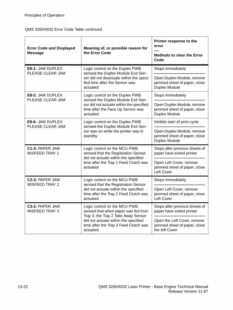
13
Principles of Operation
QMS 3260/4032 Error Code Table continued
Error Code and Displayed Message
Meaning of, or possible reason for the Error Code
Printer response to the error----Methods to clear the Error Code
E8-1: JAM DUPLEXPLEASE CLEAR JAM
Logic control on the Duplex PWB sensed the Duplex Module Exit Sen-sor did not deactuate within the speci-fied time after the Sensor was actuated
Stops immediately---------------------------------------Open Duplex Module, remove jammed sheet of paper, close Duplex Module
E8-2: JAM DUPLEXPLEASE CLEAR JAM
Logic control on the Duplex PWB sensed the Duplex Module Exit Sen-sor did not actuate within the specified time after the Face Up Sensor was actuated
Stops immediately---------------------------------------Open Duplex Module, remove jammed sheet of paper, close Duplex Module
E8-6: JAM DUPLEXPLEASE CLEAR JAM
Logic control on the Duplex PWB sensed the Duplex Module Exit Sen-sor was on while the printer was in standby
Inhibits start of print cycle---------------------------------------Open Duplex Module, remove jammed sheet of paper, close Duplex Module
C1-3: PAPER JAMMISFEED TRAY 1
Logic control on the MCU PWB sensed that the Registration Sensor did not actuate within the specified time after the Tray 1 Feed Clutch was actuated
Stops after previous sheets of paper have exited printer---------------------------------------Open Left Cover, remove jammed sheet of paper, close Left Cover
C2-3: PAPER JAMMISFEED TRAY 2
Logic control on the MCU PWB sensed that the Registration Sensor did not actuate within the specified time after the Tray 2 Feed Clutch was actuated
Stops immediately---------------------------------------Open Left Cover, remove jammed sheet of paper, close Left Cover
C3-2: PAPER JAMMISFEED TRAY 3
Logic control on the MCU PWB sensed that when paper was fed from Tray 3, the Tray 2 Take Away Sensor did not actuate within the specified time after the Tray 3 Feed Clutch was actuated
Stops after previous sheets of paper have exited printer---------------------------------------Open the Left Cover, remove jammed sheet of paper, close the left Cover
-22 QMS 3260/4032 Laser Printer - Base Engine Technical Manual Release Version 11-97
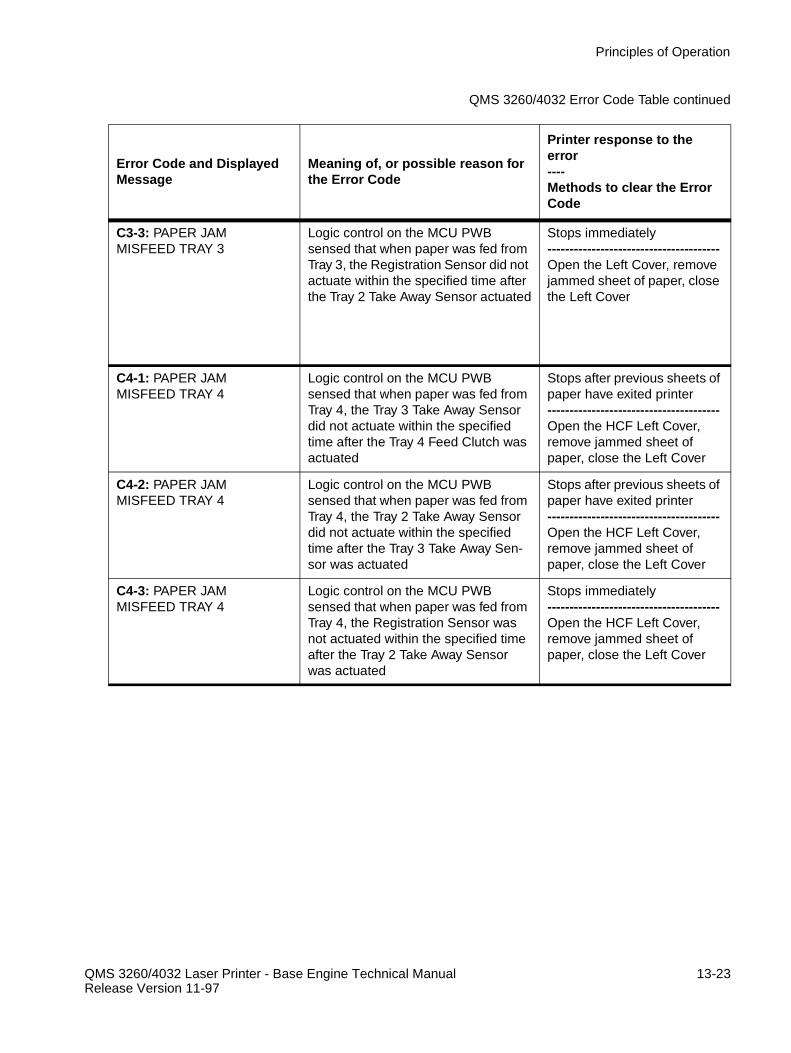
QMRe
Principles of Operation
QMS 3260/4032 Error Code Table continued
Error Code and Displayed Message
Meaning of, or possible reason for the Error Code
Printer response to the error----Methods to clear the Error Code
C3-3: PAPER JAMMISFEED TRAY 3
Logic control on the MCU PWB sensed that when paper was fed from Tray 3, the Registration Sensor did not actuate within the specified time after the Tray 2 Take Away Sensor actuated
Stops immediately---------------------------------------Open the Left Cover, remove jammed sheet of paper, close the Left Cover
C4-1: PAPER JAMMISFEED TRAY 4
Logic control on the MCU PWB sensed that when paper was fed from Tray 4, the Tray 3 Take Away Sensor did not actuate within the specified time after the Tray 4 Feed Clutch was actuated
Stops after previous sheets of paper have exited printer---------------------------------------Open the HCF Left Cover, remove jammed sheet of paper, close the Left Cover
C4-2: PAPER JAMMISFEED TRAY 4
Logic control on the MCU PWB sensed that when paper was fed from Tray 4, the Tray 2 Take Away Sensor did not actuate within the specified time after the Tray 3 Take Away Sen-sor was actuated
Stops after previous sheets of paper have exited printer---------------------------------------Open the HCF Left Cover, remove jammed sheet of paper, close the Left Cover
C4-3: PAPER JAMMISFEED TRAY 4
Logic control on the MCU PWB sensed that when paper was fed from Tray 4, the Registration Sensor was not actuated within the specified time after the Tray 2 Take Away Sensor was actuated
Stops immediately---------------------------------------Open the HCF Left Cover, remove jammed sheet of paper, close the Left Cover
S 3260/4032 Laser Printer - Base Engine Technical Manual 13-23lease Version 11-97
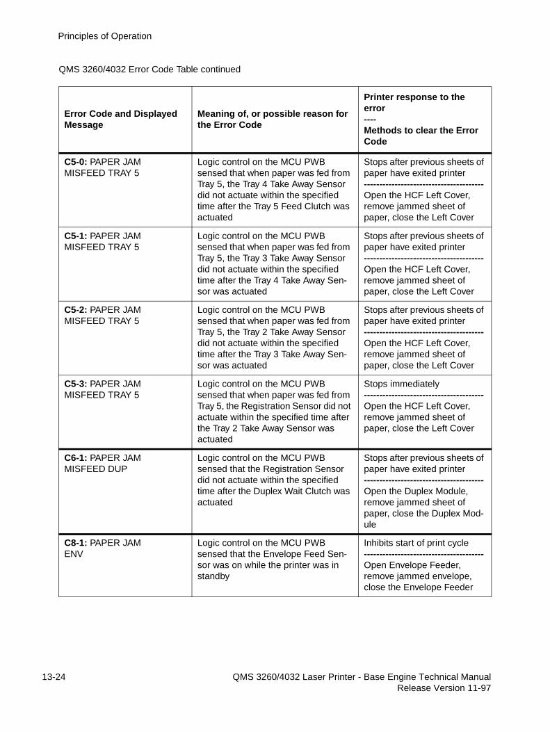
13
Principles of Operation
QMS 3260/4032 Error Code Table continued
Error Code and Displayed Message
Meaning of, or possible reason for the Error Code
Printer response to the error----Methods to clear the Error Code
C5-0: PAPER JAMMISFEED TRAY 5
Logic control on the MCU PWB sensed that when paper was fed from Tray 5, the Tray 4 Take Away Sensor did not actuate within the specified time after the Tray 5 Feed Clutch was actuated
Stops after previous sheets of paper have exited printer---------------------------------------Open the HCF Left Cover, remove jammed sheet of paper, close the Left Cover
C5-1: PAPER JAMMISFEED TRAY 5
Logic control on the MCU PWB sensed that when paper was fed from Tray 5, the Tray 3 Take Away Sensor did not actuate within the specified time after the Tray 4 Take Away Sen-sor was actuated
Stops after previous sheets of paper have exited printer---------------------------------------Open the HCF Left Cover, remove jammed sheet of paper, close the Left Cover
C5-2: PAPER JAMMISFEED TRAY 5
Logic control on the MCU PWB sensed that when paper was fed from Tray 5, the Tray 2 Take Away Sensor did not actuate within the specified time after the Tray 3 Take Away Sen-sor was actuated
Stops after previous sheets of paper have exited printer---------------------------------------Open the HCF Left Cover, remove jammed sheet of paper, close the Left Cover
C5-3: PAPER JAMMISFEED TRAY 5
Logic control on the MCU PWB sensed that when paper was fed from Tray 5, the Registration Sensor did not actuate within the specified time after the Tray 2 Take Away Sensor was actuated
Stops immediately---------------------------------------Open the HCF Left Cover, remove jammed sheet of paper, close the Left Cover
C6-1: PAPER JAMMISFEED DUP
Logic control on the MCU PWB sensed that the Registration Sensor did not actuate within the specified time after the Duplex Wait Clutch was actuated
Stops after previous sheets of paper have exited printer---------------------------------------Open the Duplex Module, remove jammed sheet of paper, close the Duplex Mod-ule
C8-1: PAPER JAMENV
Logic control on the MCU PWB sensed that the Envelope Feed Sen-sor was on while the printer was in standby
Inhibits start of print cycle---------------------------------------Open Envelope Feeder, remove jammed envelope, close the Envelope Feeder
-24 QMS 3260/4032 Laser Printer - Base Engine Technical Manual Release Version 11-97
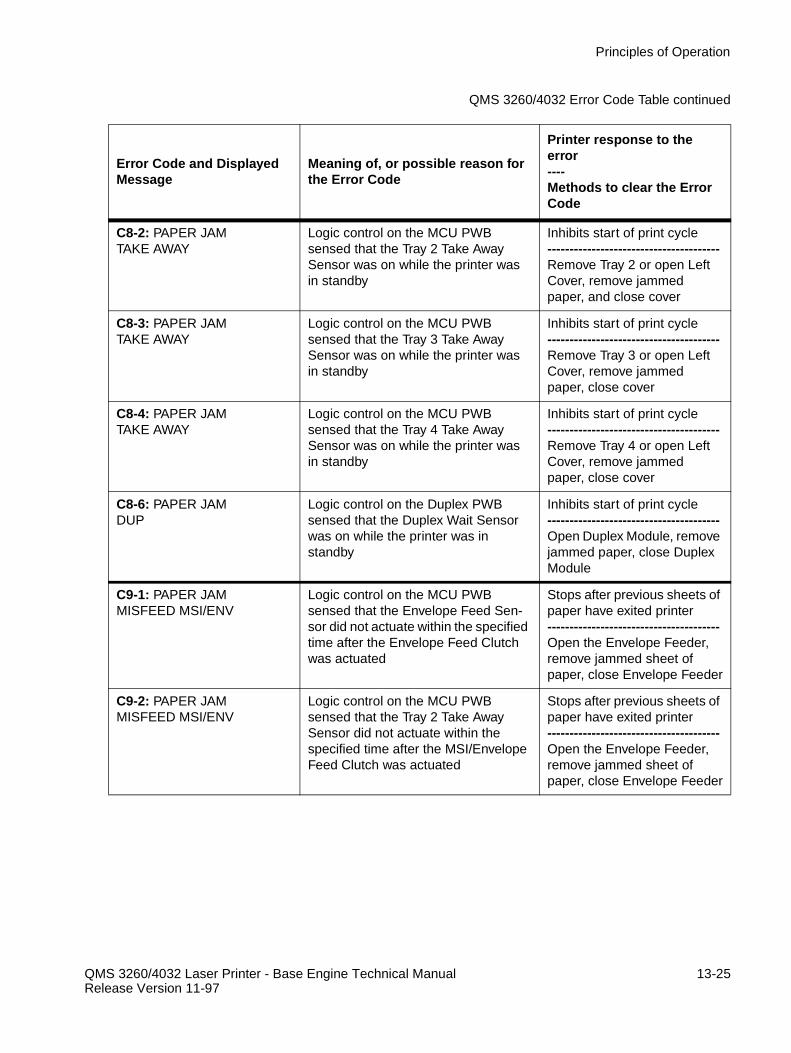
QMRe
Principles of Operation
QMS 3260/4032 Error Code Table continued
Error Code and Displayed Message
Meaning of, or possible reason for the Error Code
Printer response to the error----Methods to clear the Error Code
C8-2: PAPER JAMTAKE AWAY
Logic control on the MCU PWB sensed that the Tray 2 Take Away Sensor was on while the printer was in standby
Inhibits start of print cycle---------------------------------------Remove Tray 2 or open Left Cover, remove jammed paper, and close cover
C8-3: PAPER JAMTAKE AWAY
Logic control on the MCU PWB sensed that the Tray 3 Take Away Sensor was on while the printer was in standby
Inhibits start of print cycle---------------------------------------Remove Tray 3 or open Left Cover, remove jammed paper, close cover
C8-4: PAPER JAMTAKE AWAY
Logic control on the MCU PWB sensed that the Tray 4 Take Away Sensor was on while the printer was in standby
Inhibits start of print cycle---------------------------------------Remove Tray 4 or open Left Cover, remove jammed paper, close cover
C8-6: PAPER JAMDUP
Logic control on the Duplex PWB sensed that the Duplex Wait Sensor was on while the printer was in standby
Inhibits start of print cycle---------------------------------------Open Duplex Module, remove jammed paper, close Duplex Module
C9-1: PAPER JAMMISFEED MSI/ENV
Logic control on the MCU PWB sensed that the Envelope Feed Sen-sor did not actuate within the specified time after the Envelope Feed Clutch was actuated
Stops after previous sheets of paper have exited printer---------------------------------------Open the Envelope Feeder, remove jammed sheet of paper, close Envelope Feeder
C9-2: PAPER JAMMISFEED MSI/ENV
Logic control on the MCU PWB sensed that the Tray 2 Take Away Sensor did not actuate within the specified time after the MSI/Envelope Feed Clutch was actuated
Stops after previous sheets of paper have exited printer---------------------------------------Open the Envelope Feeder, remove jammed sheet of paper, close Envelope Feeder
S 3260/4032 Laser Printer - Base Engine Technical Manual 13-25lease Version 11-97

13
Principles of Operation
QMS 3260/4032 Error Code Table continued
Error Code and Displayed Message
Meaning of, or possible reason for the Error Code
Printer response to the error----Methods to clear the Error Code
C9-3: PAPER JAMMISFEED MSI/ENV
Logic control on the MCU PWB sensed that when paper was fed from the MSI or Envelope Feeder, that the Registration Sensor did not actuate within the specified time after the MSI/Envelope Feed Clutch was actuated
Stops immediately---------------------------------------Open the Envelope Feeder, remove jammed sheet of paper, close the Envelope Feeder
F2-1: PAPER JAMMAILBOX IN SENSOR
Logic control on the MCU PWB sensed that the Mailbox Entrance Sensor did not actuate within the specified time after the Fuser Exit Sensor was actuated
Stops immediately---------------------------------------Open the Mailbox Left Cover, remove jammed sheet of paper, and close the Left Cover
F2-2: PAPER JAMMAILBOX IN SENSOR
Logic control on the MCU PWB sensed that the Mailbox Entrance Sensor did not deactuate within the specified time after the Sensor was actuated
Stops immediately---------------------------------------Open the Mailbox Left Cover, remove jammed sheet of paper, and close the Left Cover
F2-3: PAPER JAMMAILBOX IN SENSOR
Logic control on the MCU PWB sensed that the Mailbox Entrance Sensor was actuated while the printer was not in Mailbox mode
Stops immediately---------------------------------------Open the Mailbox Left Cover, remove jammed sheet of paper, and close the Left Cover
F2-6: PAPER JAMMAILBOX IN SENSOR
Logic control on the MCU PWB sensed that the Mailbox Entrance Sensor was on while the printer was in standby
Inhibits start of print cycle---------------------------------------Open the Mailbox Left Cover, remove jammed sheet of paper, and close the Left Cover
-26 QMS 3260/4032 Laser Printer - Base Engine Technical Manual Release Version 11-97

QMRe
Principles of Operation
QMS 3260/4032 Error Code Table continued
Error Code and Displayed Message
Meaning of, or possible reason for the Error Code
Printer response to the error----Methods to clear the Error Code
F3-1: PAPER JAMMAILBOX VERTICAL SEN-SOR
Logic control on the MCU PWB sensed that either the Mailbox Vertical Sensor did not actuate within the specified time after the Mailbox Entrance Sensor was actuated or that BIN 1 Jam Sensor did not actuate within the specified time after the Mailbox Entrance Sensor was actu-ated
Stops immediately---------------------------------------Open the Mailbox Left Cover, remove jammed sheet of paper, and close the Left Cover
F3-2: PAPER JAMMAILBOX VERTICAL SEN-SOR
Logic control on the MCU PWB sensed that either the Mailbox Vertical Sensor did not actuate within the specified time after the Mailbox Entrance Sensor was actuated or that BIN 1 Jam Sensor did not deactuate within the specified time after the BIN1 Jam Sensor was actuated
Stops immediately---------------------------------------Open the Mailbox Left Cover, remove jammed sheet of paper, and close the Left Cover
F3-6: PAPER JAMMAILBOX SENSOR
Logic control on the MCU PWB sensed that either the Mailbox Vertical Sensor or the BIN 1 Jam Sensor did not deactuated within the specified time after they were actuated
If during a print cycle; stops immediatelyIf during standby; inhibits start of print cycle---------------------------------------Open the Mailbox Left Cover, remove jammed sheet of paper, and close the Left Cover
F4-11: PAPER JAMFINISHER TRANSPORT
Logic control on the MCU PWB sensed that the Transport Entrance Sensor did not deactuate within the specified time after the Sensor was actuated
Stops immediately---------------------------------------Open the Transport Gate In Cover, remove jammed sheet of paper, and close the Cover
F4-12: PAPER JAMFINISHER TRANSPORT
Logic control on the MCU PWB sensed that the Transport Entrance Sensor did not actuate within the specified time after the Fuser Exit Sensor was deactuated
Stops after previous sheets of paper have exited printer---------------------------------------Open the Transport Gate In Cover, remove jammed sheet of paper, and close the Cover
S 3260/4032 Laser Printer - Base Engine Technical Manual 13-27lease Version 11-97
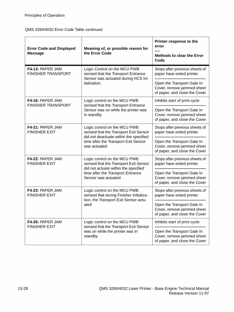
13
Principles of Operation
QMS 3260/4032 Error Code Table continued
Error Code and Displayed Message
Meaning of, or possible reason for the Error Code
Printer response to the error----Methods to clear the Error Code
F4-13: PAPER JAMFINISHER TRANSPORT
Logic Control on the MCU PWB sensed that the Transport Entrance Sensor was actuated during HCS ini-tialization.
Stops after previous sheets of paper have exited printer---------------------------------------Open the Transport Gate In Cover, remove jammed sheet of paper, and close the Cover
F4-16: PAPER JAMFINISHER TRANSPORT
Logic control on the MCU PWB sensed that the Transport Entrance Sensor was on while the printer was in standby
Inhibits start of print cycle---------------------------------------Open the Transport Gate In Cover, remove jammed sheet of paper, and close the Cover
F4-21: PAPER JAMFINISHER EXIT
Logic control on the MCU PWB sensed that the Transport Exit Sensor did not deactuate within the specified time after the Transport Exit Sensor was actuated
Stops after previous sheets of paper have exited printer---------------------------------------Open the Transport Gate In Cover, remove jammed sheet of paper, and close the Cover
F4-22: PAPER JAMFINISHER EXIT
Logic control on the MCU PWB sensed that the Transport Exit Sensor did not actuate within the specified time after the Transport Entrance Sensor was actuated
Stops after previous sheets of paper have exited printer---------------------------------------Open the Transport Gate In Cover, remove jammed sheet of paper, and close the Cover
F4-23: PAPER JAMFINISHER EXIT
Logic control on the MCU PWB sensed that during Finisher initializa-tion, the Transport Exit Sensor actu-ated
Stops after previous sheets of paper have exited printer---------------------------------------Open the Transport Gate In Cover, remove jammed sheet of paper, and close the Cover
F4-26: PAPER JAMFINISHER EXIT
Logic control on the MCU PWB sensed that the Transport Exit Sensor was on while the printer was in standby
Inhibits start of print cycle---------------------------------------Open the Transport Gate In Cover, remove jammed sheet of paper, and close the Cover
-28 QMS 3260/4032 Laser Printer - Base Engine Technical Manual Release Version 11-97

QMRe
Principles of Operation
QMS 3260/4032 Error Code Table continued
Error Code and Displayed Message
Meaning of, or possible reason for the Error Code
Printer response to the error----Methods to clear the Error Code
F4-31: PAPER JAMCOMPILE TRAY EXIT
Logic control on the MCU PWB sensed that the Compiler Tray Exit Sensor did not deactuate within the specified time after the Complier Tray Exit Sensor was actuated
Stops immediately---------------------------------------Open the Complier Cover, remove jammed sheet of paper, and close the Cover
F4-32: PAPER JAMCOMPILE TRAY EXIT
Logic control on the MCU PWB sensed that the Compiler Tray Exit Sensor did not actuate within the specified time after the Transport Exit Sensor was deactuated
Stops immediately---------------------------------------Open the Complier Cover, remove jammed sheet of paper, and close the Cover
F4-36: PAPER JAMCOMPILE TRAY EXIT
Logic control on the MCU PWB sensed that the Complier Tray Exit Sensor was on while the printer was in standby
Inhibits start of print cycle---------------------------------------Open the Complier Cover, remove jammed sheet of paper, and close the Cover
F4-41: PAPER JAMCOMPILE TRAY EXIT
Logic control on the MCU PWB sensed that the Complier Paper Sen-sor neither actuated nor deactuated within the specified time after the Eject Motor was switched on
Stops immediately---------------------------------------Open the Complier Cover, remove jammed sheet of paper, and close the Cover
F4-46: PAPER JAMCOMPILE TRAY EXIT
Logic control on the MCU PWB sensed that the Complier Paper Sen-sor was on while the printer was in standby
Inhibits start of print cycle---------------------------------------Open the Complier Cover, remove jammed sheet of paper, and close the Cover
F5-1: INTERLOCK OPENMAILBOX
Logic control on the MCU PWB sensed that the Mailbox Left Cover is open
Inhibits start of print cycle---------------------------------------Close the cover
F6-1: INTERLOCK OPENGATE IN CVR
Logic control on the MCU PWB sensed that the In Gate Cover is open
Stops after previous sheets of paper have exited printer and inhibits start of the print cycle---------------------------------------Close the Gate In Cover
F6-2: INTERLOCK OPENTRANSPORT CVR
Logic control on the MCU PWB sensed that the upper Transport Cover is open
Stops after previous sheets of paper have exited printer and inhibits start of the print cycle---------------------------------------Close the Transport Cover
S 3260/4032 Laser Printer - Base Engine Technical Manual 13-29lease Version 11-97

13
Principles of Operation
QMS 3260/4032 Error Code Table continued
Error Code and Displayed Message
Meaning of, or possible reason for the Error Code
Printer response to the error----Methods to clear the Error Code
F7-1: INTERLOCK OPENFRONT CVR
Logic control on the MCU PWB sensed that the Front Cover is open
Stops after previous sheets of paper have exited printer and inhibits start of the next print cycle---------------------------------------Close the Front Cover
F7-2: INTERLOCK OPENTOP CVR
Logic control on the MCU PWB sensed that the Top Cover is open
If during a print cycle; stops immediatelyIf during standby; inhibits start of print cycle---------------------------------------Close the Complier Cover
F7-3: SAFETY SWITCH OPEN COMPLIER CVR
Logic control on the MCU PWB sensed that the Complier Cover is open and the Complier Cover Safety Switch is not actuated
If during a print cycle; stops immediatelyIf during standby; inhibits start of print cycle---------------------------------------Close the Complier Cover Safety Switch
F7-4: INTERLOCK OPENCOMPLIER CVR
Logic control on the MCU PWB sensed that the Complier Cover is open
If during a print cycle; stops immediatelyIf during standby; inhibits start of print cycle---------------------------------------Close the Complier Cover
F8-1: INTERLOCK OPENFINISHER CVR
Logic control on the MCU PWB sensed that the Finisher Cover is open
If during a print cycle; stops immediatelyIf during standby; inhibits start of print cycle---------------------------------------Close the Finisher Cover
H1-1: TRAY FAILTRAY 1
Logic control on the MCU PWB sensed that the Tray 1 Paper Level Sensor did not actuate within the specified time after the Tray 1 Lift Up Motor was actuated
Inhibits use of Tray 1---------------------------------------Reinsert Tray 1 or switch power off, then on
-30 QMS 3260/4032 Laser Printer - Base Engine Technical Manual Release Version 11-97
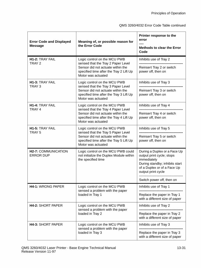
QMRe
Principles of Operation
QMS 3260/4032 Error Code Table continued
Error Code and Displayed Message
Meaning of, or possible reason for the Error Code
Printer response to the error----Methods to clear the Error Code
H1-2: TRAY FAILTRAY 2
Logic control on the MCU PWB sensed that the Tray 2 Paper Level Sensor did not actuate within the specified time after the Tray 2 Lift Up Motor was actuated
Inhibits use of Tray 2---------------------------------------Reinsert Tray 2 or switch power off, then on
H1-3: TRAY FAILTRAY 3
Logic control on the MCU PWB sensed that the Tray 3 Paper Level Sensor did not actuate within the specified time after the Tray 3 Lift Up Motor was actuated
Inhibits use of Tray 3---------------------------------------Reinsert Tray 3 or switch power off, then on
H1-4: TRAY FAILTRAY 4
Logic control on the MCU PWB sensed that the Tray 4 Paper Level Sensor did not actuate within the specified time after the Tray 4 Lift Up Motor was actuated
Inhibits use of Tray 4---------------------------------------Reinsert Tray 4 or switch power off, then on
H1-5: TRAY FAILTRAY 5
Logic control on the MCU PWB sensed that the Tray 5 Paper Level Sensor did not actuate within the specified time after the Tray 5 Lift Up Motor was actuated
Inhibits use of Tray 5---------------------------------------Reinsert Tray 5 or switch power off, then on
H2-7: COMMUNICATIONERROR DUP
Logic control on the MCU PWB could not initialize the Duplex Module within the specified time
During a Duplex or a Face Up output print cycle; stops immediatelyDuring standby; inhibits start of a Duplex or of a Face Up output print cycle---------------------------------------Switch power off, then on
H4-1: WRONG PAPER Logic control on the MCU PWB sensed a problem with the paper loaded in Tray 1
Inhibits use of Tray 1---------------------------------------Replace the paper in Tray 1 with a different size of paper
H4-2: SHORT PAPER Logic control on the MCU PWB sensed a problem with the paper loaded in Tray 2
Inhibits use of Tray 2---------------------------------------Replace the paper in Tray 2 with a different size of paper
H4-3: SHORT PAPER Logic control on the MCU PWB sensed a problem with the paper loaded in Tray 3
Inhibits use of Tray 3---------------------------------------Replace the paper in Tray 3 with a different size of paper
S 3260/4032 Laser Printer - Base Engine Technical Manual 13-31lease Version 11-97

13
Principles of Operation
QMS 3260/4032 Error Code Table continued
Error Code and Displayed Message
Meaning of, or possible reason for the Error Code
Printer response to the error----Methods to clear the Error Code
H4-4: SHORT PAPER Logic control on the MCU PWB sensed a problem with the paper loaded in Tray 4
Inhibits use of Tray 4---------------------------------------Replace the paper in Tray 4 with a different size of paper
H4-5: SHORT PAPER Logic control on the MCU PWB sensed a problem with the paper loaded in Tray 5
Inhibits use of Tray 5---------------------------------------Replace the paper in Tray 5 with a different size of paper
H5-7: COMMUNICATION FAIL MAILBOX
Logic control on the MCU PWB could not initialize the Mailbox within the specified time
During Mailbox mode print cycle; stops immediatelyDuring standby; inhibits start of a Mailbox Mode print cycle---------------------------------------Switch power off, then on
H5-11: STACKER TRAY 1FAILURE
Logic control on the MCU PWB sensed the Stack Height Sensor either did not actuate within the speci-fied time after the Stacker Tray 1 Motor switched on to raise Tray 1 or did not deactuate within the specified time after the Stacker Tray 1 Motor switch on to lower Tray 1
Stops immediately---------------------------------------Switch power off, then on
H5-12: STACKER TRAY 2FAILURE
Logic control on the MCU PWB sensed the Stack Height Sensor either did not actuate within the speci-fied time after the Stacker Tray 2 Motor switched on to raise Tray 2 or did not deactuate within the specified time after the Stacker Tray 2 Motor switch on to lower Tray 2
Stops immediately---------------------------------------Switch power off, then on
H5-13: STACKER TRAY 3FAILURE
Logic control on the MCU PWB sensed the Stack Height Sensor either did not actuate within the speci-fied time after the Stacker Tray 3 Motor switched on to raise Tray 3 or did not deactuate within the specified time after the Stacker Tray 3 Motor switch on to lower Tray 3
Stops immediately---------------------------------------Switch power off, then on
-32 QMS 3260/4032 Laser Printer - Base Engine Technical Manual Release Version 11-97
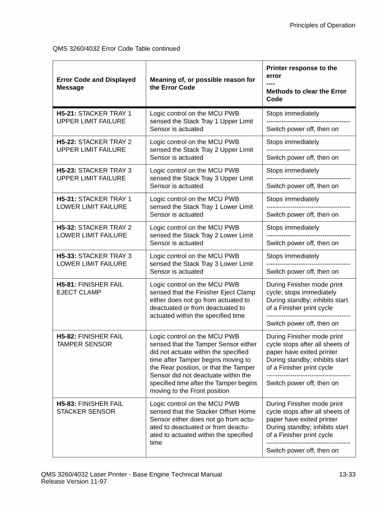
QMRe
Principles of Operation
QMS 3260/4032 Error Code Table continued
Error Code and Displayed Message
Meaning of, or possible reason for the Error Code
Printer response to the error----Methods to clear the Error Code
H5-21: STACKER TRAY 1UPPER LIMIT FAILURE
Logic control on the MCU PWB sensed the Stack Tray 1 Upper Limit Sensor is actuated
Stops immediately---------------------------------------Switch power off, then on
H5-22: STACKER TRAY 2UPPER LIMIT FAILURE
Logic control on the MCU PWB sensed the Stack Tray 2 Upper Limit Sensor is actuated
Stops immediately---------------------------------------Switch power off, then on
H5-23: STACKER TRAY 3UPPER LIMIT FAILURE
Logic control on the MCU PWB sensed the Stack Tray 3 Upper Limit Sensor is actuated
Stops immediately---------------------------------------Switch power off, then on
H5-31: STACKER TRAY 1LOWER LIMIT FAILURE
Logic control on the MCU PWB sensed the Stack Tray 1 Lower Limit Sensor is actuated
Stops immediately---------------------------------------Switch power off, then on
H5-32: STACKER TRAY 2LOWER LIMIT FAILURE
Logic control on the MCU PWB sensed the Stack Tray 2 Lower Limit Sensor is actuated
Stops immediately---------------------------------------Switch power off, then on
H5-33: STACKER TRAY 3LOWER LIMIT FAILURE
Logic control on the MCU PWB sensed the Stack Tray 3 Lower Limit Sensor is actuated
Stops immediately---------------------------------------Switch power off, then on
H5-81: FINISHER FAILEJECT CLAMP
Logic control on the MCU PWB sensed that the Finisher Eject Clamp either does not go from actuated to deactuated or from deactuated to actuated within the specified time
During Finisher mode print cycle; stops immediatelyDuring standby; inhibits start of a Finisher print cycle---------------------------------------Switch power off, then on
H5-82: FINISHER FAILTAMPER SENSOR
Logic control on the MCU PWB sensed that the Tamper Sensor either did not actuate within the specified time after Tamper begins moving to the Rear position, or that the Tamper Sensor did not deactuate within the specified time after the Tamper begins moving to the Front position
During Finisher mode print cycle stops after all sheets of paper have exited printer During standby; inhibits start of a Finisher print cycle---------------------------------------Switch power off, then on
H5-83: FINISHER FAILSTACKER SENSOR
Logic control on the MCU PWB sensed that the Stacker Offset Home Sensor either does not go from actu-ated to deactuated or from deactu-ated to actuated within the specified time
During Finisher mode print cycle stops after all sheets of paper have exited printer During standby; inhibits start of a Finisher print cycle---------------------------------------Switch power off, then on
S 3260/4032 Laser Printer - Base Engine Technical Manual 13-33lease Version 11-97

13
Principles of Operation
QMS 3260/4032 Error Code Table continued
Error Code and Displayed Message
Meaning of, or possible reason for the Error Code
Printer response to the error----Methods to clear the Error Code
H5-84: FINISHER FAILSTACKER TRAY ID
Logic control on the MCU PWB sensed that the Stacker Tray ID Sen-sor either does not go from actuated to deactuated or from deactuated to actuated within the specified time after the Stacker Tray Unit Elevator Motor is switched on
During Finisher mode; stops immediatelyDuring standby; inhibits start of a Finisher print cycle---------------------------------------Switch power off, then on
H5-85: FINISHER FAILSTACKER SWITCH
Logic control on the MCU PWB sensed that the Stacker Upper Limit Switch is actuated
During Finisher mode; stops immediatelyDuring standby; inhibits start of a Finisher print cycle---------------------------------------Switch power off, then on
H5-86: FINISHER FAILSTACKER SWITCH
Logic control on the MCU PWB sensed that the Stacker Lower Limit Switch is actuated
During Finisher mode; stops immediatelyDuring standby; inhibits start of a Finisher print cycle---------------------------------------Switch power off, then on
H5-91: FINISHER FAILSTAPLER HEAD
Logic control on the MCU PWB sensed that the Stapler Home Sensor remains deactuated after the Stapler Head started return
During Finisher mode; stops immediatelyDuring standby; inhibits start of a Finisher print cycle---------------------------------------Switch power off, then on
H5-92: FINISHER FAILSTAPLER HEAD
Logic control on the MCU PWB sensed that the Home Sensor does not actuate within the specified time after the Stapler Motor was switched on
During Finisher mode; stops immediatelyDuring standby; inhibits start of a Finisher print cycle---------------------------------------Switch power off, then on
H5-93: FINISHER FAILSTAPLER PRINT CORNER
Logic control on the MCU PWB sensed that the Stapler Front Corner Sensor does not actuate within the specified time after the Stapler Move Motor is switched on
During Finisher mode; stops immediatelyDuring standby; inhibits start of a Finisher print cycle---------------------------------------Switch power off, then on
-34 QMS 3260/4032 Laser Printer - Base Engine Technical Manual Release Version 11-97

QMRe
Principles of Operation
QMS 3260/4032 Error Code Table continued
Error Code and Displayed Message
Meaning of, or possible reason for the Error Code
Printer response to the error----Methods to clear the Error Code
H5-94: FINISHER FAILSTAPLER FRONT STRAIGHT
Logic control on the MCU PWB sensed that the Stapler Front Straight Sensor does not actuate within the specified time after the Stapler Move Motor is switched on
During Finisher mode; stops immediatelyDuring standby; inhibits start of a Finisher print cycle---------------------------------------Switch power off, then on
H5-95: FINISHER FAILSTAPLER REAR STRAIGHT
Logic control on the MCU PWB sensed that the Stapler Rear Straight Sensor does not actuate within the specified time after the Stapler Move Motor is switched on
During Finisher mode; stops immediatelyDuring standby; inhibits start of a Finisher print cycle---------------------------------------Switch power off, then on
H5-96: FINISHER FAILSTAPLER READY SENSOR
Logic control on the MCU PWB sensed that the Set Clamp Home Sensor does not actuate nor deactu-ate within the specified time after the Set Clamp Motor is switched on
During Finisher mode; stops immediatelyDuring standby; inhibits start of a Finisher print cycle---------------------------------------Switch power off, then on
H5-97: FINISHER FAILSTAPLER WALL SENSOR
Logic control on the MCU PWB sensed that the Stapler End Wall Sen-sor either does not go from actuated to deactuated or from deactuated to actuated within the specified time
During Finisher mode; stops immediatelyDuring standby; inhibits start of a Finisher print cycle---------------------------------------Switch power off, then on
H6-7: COMMUNICATION FAIL FINISHER
Logic control on the MCU PWB could not initialize the Finisher within the specified time
During Finisher mode; stops immediatelyDuring standby; inhibits start of a Finisher print cycle---------------------------------------Switch power off, then on
J1-2: TONER EMPTY Logic control on the MCU PWB sensed that the Toner Empty Sensor was on for longer than 9 seconds
If code 50-01 is set to zero, the printer does nothingIf code 50-01 is set to 1, then stops after all sheets of paper have exited printer ---------------------------------------EitherOpen and close the Left Cover, or Switch power off, then on, or replace the EP Cartridge
S 3260/4032 Laser Printer - Base Engine Technical Manual 13-35lease Version 11-97
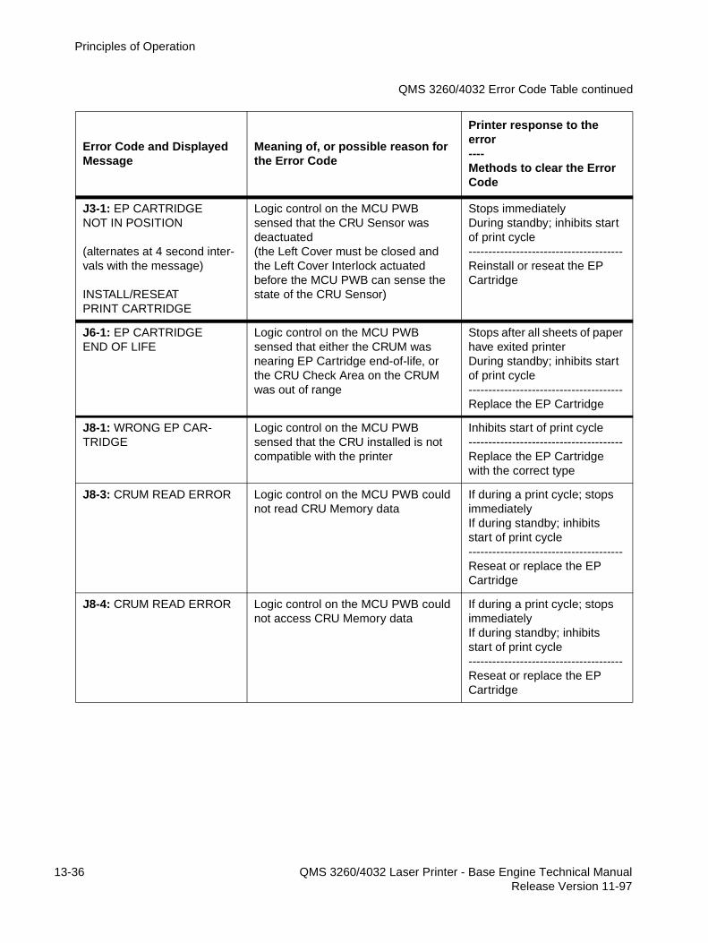
13
Principles of Operation
QMS 3260/4032 Error Code Table continued
Error Code and Displayed Message
Meaning of, or possible reason for the Error Code
Printer response to the error----Methods to clear the Error Code
J3-1: EP CARTRIDGENOT IN POSITION
(alternates at 4 second inter-vals with the message)
INSTALL/RESEATPRINT CARTRIDGE
Logic control on the MCU PWB sensed that the CRU Sensor was deactuated(the Left Cover must be closed and the Left Cover Interlock actuated before the MCU PWB can sense the state of the CRU Sensor)
Stops immediatelyDuring standby; inhibits start of print cycle---------------------------------------Reinstall or reseat the EP Cartridge
J6-1: EP CARTRIDGEEND OF LIFE
Logic control on the MCU PWB sensed that either the CRUM was nearing EP Cartridge end-of-life, or the CRU Check Area on the CRUM was out of range
Stops after all sheets of paper have exited printerDuring standby; inhibits start of print cycle---------------------------------------Replace the EP Cartridge
J8-1: WRONG EP CAR-TRIDGE
Logic control on the MCU PWB sensed that the CRU installed is not compatible with the printer
Inhibits start of print cycle---------------------------------------Replace the EP Cartridge with the correct type
J8-3: CRUM READ ERROR Logic control on the MCU PWB could not read CRU Memory data
If during a print cycle; stops immediatelyIf during standby; inhibits start of print cycle---------------------------------------Reseat or replace the EP Cartridge
J8-4: CRUM READ ERROR Logic control on the MCU PWB could not access CRU Memory data
If during a print cycle; stops immediatelyIf during standby; inhibits start of print cycle---------------------------------------Reseat or replace the EP Cartridge
-36 QMS 3260/4032 Laser Printer - Base Engine Technical Manual Release Version 11-97
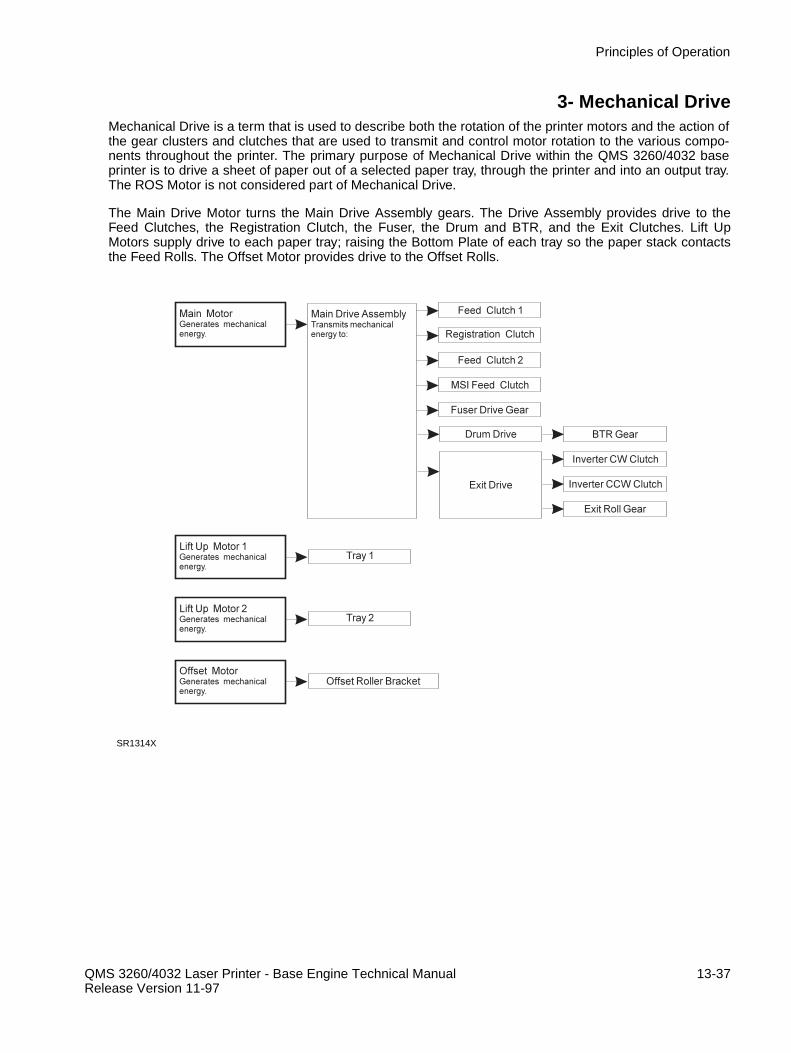
QMRe
Principles of Operation
3- Mechanical DriveMechanical Drive is a term that is used to describe both the rotation of the printer motors and the action ofthe gear clusters and clutches that are used to transmit and control motor rotation to the various compo-nents throughout the printer. The primary purpose of Mechanical Drive within the QMS 3260/4032 baseprinter is to drive a sheet of paper out of a selected paper tray, through the printer and into an output tray.The ROS Motor is not considered part of Mechanical Drive.
The Main Drive Motor turns the Main Drive Assembly gears. The Drive Assembly provides drive to theFeed Clutches, the Registration Clutch, the Fuser, the Drum and BTR, and the Exit Clutches. Lift UpMotors supply drive to each paper tray; raising the Bottom Plate of each tray so the paper stack contactsthe Feed Rolls. The Offset Motor provides drive to the Offset Rolls.
SR1314X
S 3260/4032 Laser Printer - Base Engine Technical Manual 13-37lease Version 11-97

13
Principles of Operation
Mechanical Drive Components
The QMS 3260/4032 Mechanical Drive is make up of 4 major components.
1. Offset Motor
A +24VDC motor.
2. Main Drive Assembly
Contains the +24VDC Main Drive Motor and the Main Drive Assembly gears. The Main Motor isattached to the Main Drive Assembly.
3. Lift Up Motor 1
A +24VDC motor.
4. Lift Up Motor 2
A +24VDC motor.
SR1345X
-38 QMS 3260/4032 Laser Printer - Base Engine Technical Manual Release Version 11-97
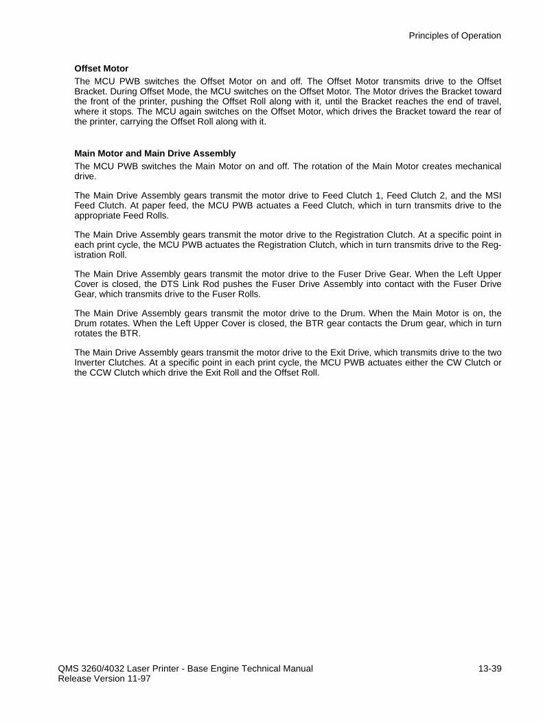
QMRe
Principles of Operation
Offset MotorThe MCU PWB switches the Offset Motor on and off. The Offset Motor transmits drive to the OffsetBracket. During Offset Mode, the MCU switches on the Offset Motor. The Motor drives the Bracket towardthe front of the printer, pushing the Offset Roll along with it, until the Bracket reaches the end of travel,where it stops. The MCU again switches on the Offset Motor, which drives the Bracket toward the rear ofthe printer, carrying the Offset Roll along with it.
Main Motor and Main Drive AssemblyThe MCU PWB switches the Main Motor on and off. The rotation of the Main Motor creates mechanicaldrive.
The Main Drive Assembly gears transmit the motor drive to Feed Clutch 1, Feed Clutch 2, and the MSIFeed Clutch. At paper feed, the MCU PWB actuates a Feed Clutch, which in turn transmits drive to theappropriate Feed Rolls.
The Main Drive Assembly gears transmit the motor drive to the Registration Clutch. At a specific point ineach print cycle, the MCU PWB actuates the Registration Clutch, which in turn transmits drive to the Reg-istration Roll.
The Main Drive Assembly gears transmit the motor drive to the Fuser Drive Gear. When the Left UpperCover is closed, the DTS Link Rod pushes the Fuser Drive Assembly into contact with the Fuser DriveGear, which transmits drive to the Fuser Rolls.
The Main Drive Assembly gears transmit the motor drive to the Drum. When the Main Motor is on, theDrum rotates. When the Left Upper Cover is closed, the BTR gear contacts the Drum gear, which in turnrotates the BTR.
The Main Drive Assembly gears transmit the motor drive to the Exit Drive, which transmits drive to the twoInverter Clutches. At a specific point in each print cycle, the MCU PWB actuates either the CW Clutch orthe CCW Clutch which drive the Exit Roll and the Offset Roll.
S 3260/4032 Laser Printer - Base Engine Technical Manual 13-39lease Version 11-97

13
Principles of Operation
Lift Up Motors 1 and 2When a Paper Tray is installed in the printer, the MCU PWB switches on the Lift Up Motor. Each tray has asquare metal shaft running along one side of the tray. Attached to the shaft is an L shaped metal tongue.When the tray is inserted into the paper feeder, a pin at the end of the shaft engages the Lift Up Motorgear. When the MCU PWB switches on the Lift Up Motor, the motor rotates the square shaft. The squareshaft shifts the attached metal tongue, which in turn raises the tray Bottom Plate which raises the paperstack. As the paper stack raises, it pushes up on the No Paper Actuator, which in turn switches the NoPaper Sensor.
SR1494X
-40 QMS 3260/4032 Laser Printer - Base Engine Technical Manual Release Version 11-97
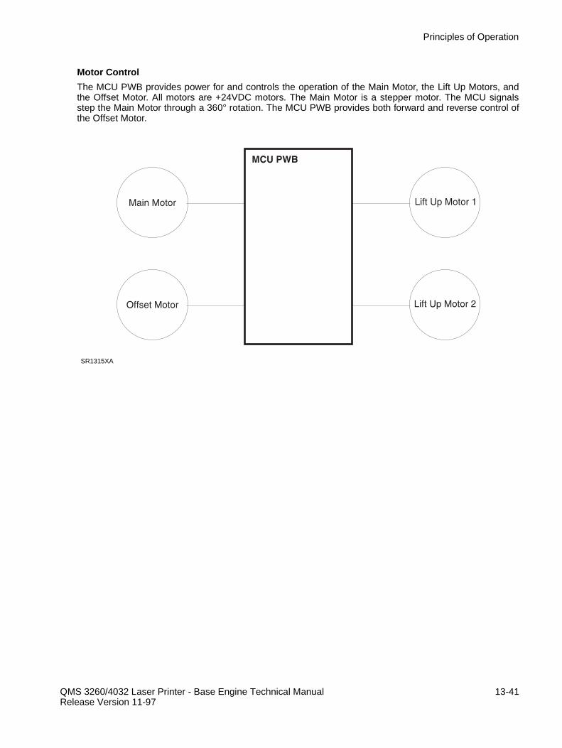
QMRe
Principles of Operation
Motor Control
The MCU PWB provides power for and controls the operation of the Main Motor, the Lift Up Motors, andthe Offset Motor. All motors are +24VDC motors. The Main Motor is a stepper motor. The MCU signalsstep the Main Motor through a 360° rotation. The MCU PWB provides both forward and reverse control ofthe Offset Motor.
SR1315XA
S 3260/4032 Laser Printer - Base Engine Technical Manual 13-41lease Version 11-97

13
Principles of Operation
4 - The Paper PathThe Paper Path is the physical route that a sheet of paper takes through the printer during a print cycle;from leaving the Paper Cassette to arriving at the Output Tray. Rubber rollers and other components drivethe paper along the Paper Path.
A sheet of paper may be fed from either Tray 1, Tray 2, or from the MSI. At the start of a print cycle theNudger Roll moves a sheet of paper into the Feed Roll. The Feed Roll moves a single sheet of paper out ofTray 1/Tray 2/MSI and toward the Registration Roll. The Retard Rolls in Tray 1 and Tray 2 or the Retard Padin the MSI made sure that only one sheet of paper is fed. If the paper was fed from Tray 2 or the MSI theTake Away Roll drives the paper to the Registration Roll. The Registration Roll aligns the lead edge of thepaper with the lead edge of the image on the drum. The Registration Roll then drives the paper into theDrum/BTR area. The rotation of the Drum and BTR drive the paper into the Fuser where the Heat andPressure Rolls drive the paper into the Offset/Pinch Roll. During simplex printing the Offset Roll drives thepaper into the Output tray. During duplex printing, the Offset Roll rotation is reversed and the Offset andExit Roll drives the paper into the Duplex Module.
SR1316X
SR1317X
-42 QMS 3260/4032 Laser Printer - Base Engine Technical Manual Release Version 11-97

QMRe
Principles of Operation
Paper Path ComponentsThe QMS 3260/4032 Paper Path is made up of a number of major components and subcomponents.
1. Tray Assembly
Holds plain paper of various sizes. Slides into the Feeder.
2. Feeder 1 and Feeder 2
Framework that is attached under the printer. A Tray Assembly slides into the Feeder. The Feederincludes a number of paper feed components.
Lift Up Motor raises the Tray Bottom Plate so the paper contacts the Feed Roll.
No Paper Sensor monitors the level of paper in the Tray.
Paper Size Sensor monitors the size of paper in the Tray.
Feed Clutch transmits drive to the Feed Roll and Nudger Roll.
Nudger Roll drives the top sheet of paper into the Feed Roll.
Feed Roll drives the top sheet of paper out of the Tray.
Retard Roll prevents multiple sheet feed.
Take Away Roll and Pinch Roll continue to drive the sheet of paper out of Tray 2 and toward the Reg-istration Roll.
3. MSI Feeder
Paper feed assembly that is attached to the outside of the printer. A small quantity or paper, or theoptional Envelope Feeder, fit on the MSI Feeder foldout tray. The MSI Feeder includes a number ofpaper feed components.
MSI No Paper Sensor monitors the level of paper in the MSI tray.
MSI Paper Size Sensor monitors the size of paper in the Tray.
MSI Feed Clutch transmits drive to the Feed Roll and Nudger Roll.
Nudger Roll drives the top sheet of paper into the Feed Roll.
Feed Roll drives the top sheet of paper out of the MSI tray.
Retard Pad prevents multiple sheet feed.
Take Away Roll and Pinch Roll continue to drive the sheet of paper out of the MSI Tray and towardthe Registration Roll.
4. Registration Roll and Pinch Roll
The Registration Roll is a driven roll. The Pinch Roll is an idler that rides on the surface of the Registra-tion Roll. The Registration Roll and Pinch Roll register a sheet of paper with the toner image on thesurface of the Drum.
5. Registration Sensor
Monitors the movement of paper at the Registration Roll.
6. Drum and BTR (Bias Transfer Roll)
In addition to xerographic functions, the Drum and BTR drive the paper out of the Xerographic areaand into the Fuser area.
7. Heat Roll and Pressure Roll
In addition to fusing functions, the Heat Roll and Pressure Roll drive the sheet of paper out of theFuser and into the Offset Unit.
S 3260/4032 Laser Printer - Base Engine Technical Manual 13-43lease Version 11-97

13
Principles of Operation
8. Fuser Exit Sensor
Monitors the movement of paper out of the Fuser.
9. Offset and Exit Unit
The assembly located above the Fuser. The Offset Unit drives paper to either the standard Face DownOutput Tray, to the optional Face Up Output Tray, or to the Duplex Module. The Offset Unit includes anumber of components.
Inverter CW and CCW Clutches transmit Main Motor drive, forward and reverse, to the Offset Rolls.
Offset Roll and Pinch Roll drive the sheet of paper either forward into the Output Tray or in reverse tothe Exit Roll and on to the Duplex Module.
Exit Gate Solenoid controls the Exit Gate to toggle the paper path between the Output Tray or the ExitRoll and on to the Face Up Tray or Duplex Module.
Offset Motor and Offset Bracket moves the Offset Roll back and forth so paper delivered to the Out-put Tray will stack offset.
Exit Roll and Pinch Roll drive the sheet of paper to either the Face Up Output Tray or to the DuplexModule.
-44 QMS 3260/4032 Laser Printer - Base Engine Technical Manual Release Version 11-97

QMRe
Principles of Operation
Paper Path Mechanical DriveThe Main Drive Assembly provides the mechanical drive for the majority of the Paper Path components. The Offset Motor provides the mechanical drive for the Offset Rolls.
SR1318X
S 3260/4032 Laser Printer - Base Engine Technical Manual 13-45lease Version 11-97

13
Principles of Operation
Mechanical drive for paper fed from the MSI
The Main Motor provides mechanical drive for MSI feed. The Drive Assembly transmits drive to the MSI Feed Clutch. The MSI Feed Roll and Nudger Roll are attached to the MSI Clutch. At paper feed, the MCU switches on the MSI Feed Clutch. The MSI Feed Clutch transmits drive to the Feed Roll, which rotates and begins feeding a single sheet of paper out of the MSI Tray. Tray 1 Feed Clutch transmits drive to the Take Away Roll. The Take Away Roll and Pinch Roll drive the sheet of paper into the Registration Roll.
SER720F
-46 QMS 3260/4032 Laser Printer - Base Engine Technical Manual Release Version 11-97

QMRe
Principles of Operation
Mechanical Drive for Paper Fed from Tray 1
The Main Motor provides mechanical drive for Tray 1 feed. The Drive Assembly transmits drive to Tray 1 Feed Clutch. Tray 1 Feed Roll and Nudger Roll are attached to the Feed Clutch. At paper feed, the MCU switches on Tray 1 Feed Clutch. The Feed Clutch transmits drive to the Feed Roll, which rotates and begins feeding a single sheet of paper out of Tray 1.
SER714F
S 3260/4032 Laser Printer - Base Engine Technical Manual 13-47lease Version 11-97
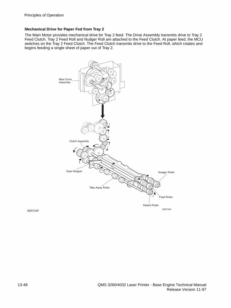
13
Principles of Operation
Mechanical Drive for Paper Fed from Tray 2
The Main Motor provides mechanical drive for Tray 2 feed. The Drive Assembly transmits drive to Tray 2 Feed Clutch. Tray 2 Feed Roll and Nudger Roll are attached to the Feed Clutch. At paper feed, the MCU switches on the Tray 2 Feed Clutch. The Feed Clutch transmits drive to the Feed Roll, which rotates and begins feeding a single sheet of paper out of Tray 2.
SER724F
-48 QMS 3260/4032 Laser Printer - Base Engine Technical Manual Release Version 11-97
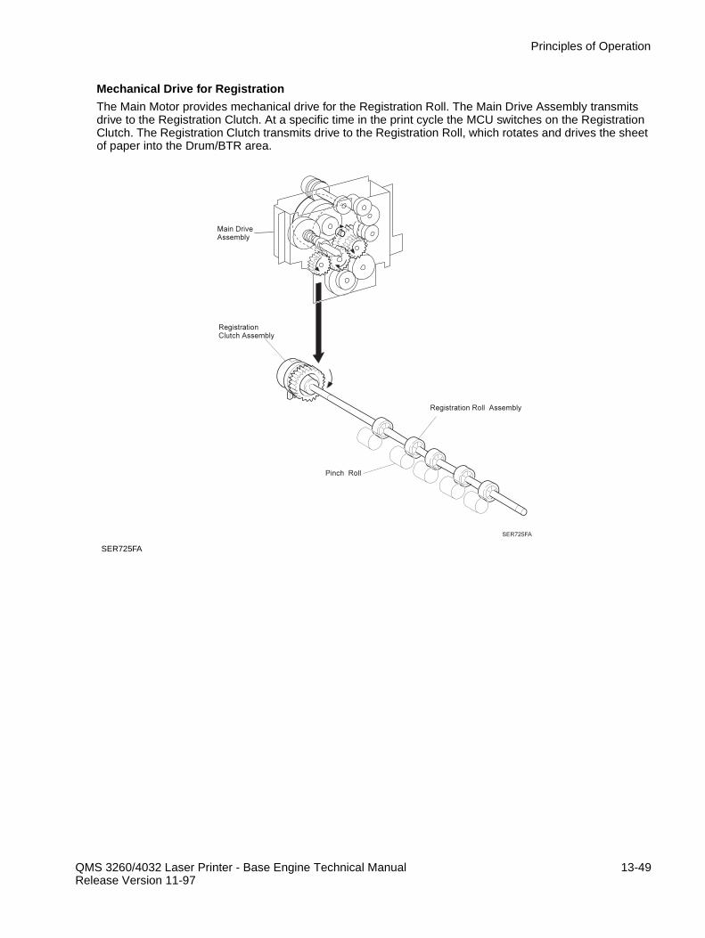
QMRe
Principles of Operation
Mechanical Drive for Registration
The Main Motor provides mechanical drive for the Registration Roll. The Main Drive Assembly transmits drive to the Registration Clutch. At a specific time in the print cycle the MCU switches on the Registration Clutch. The Registration Clutch transmits drive to the Registration Roll, which rotates and drives the sheet of paper into the Drum/BTR area.
SER725FA
S 3260/4032 Laser Printer - Base Engine Technical Manual 13-49lease Version 11-97
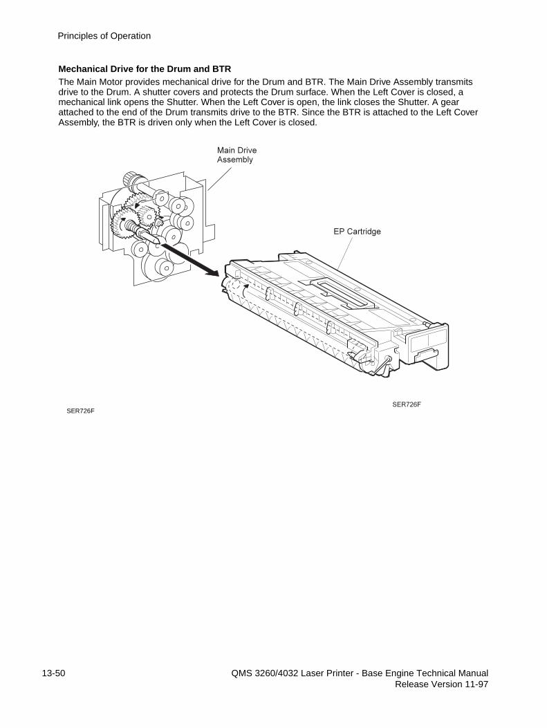
13
Principles of Operation
Mechanical Drive for the Drum and BTRThe Main Motor provides mechanical drive for the Drum and BTR. The Main Drive Assembly transmits drive to the Drum. A shutter covers and protects the Drum surface. When the Left Cover is closed, a mechanical link opens the Shutter. When the Left Cover is open, the link closes the Shutter. A gear attached to the end of the Drum transmits drive to the BTR. Since the BTR is attached to the Left Cover Assembly, the BTR is driven only when the Left Cover is closed.
SER726F
-50 QMS 3260/4032 Laser Printer - Base Engine Technical Manual Release Version 11-97
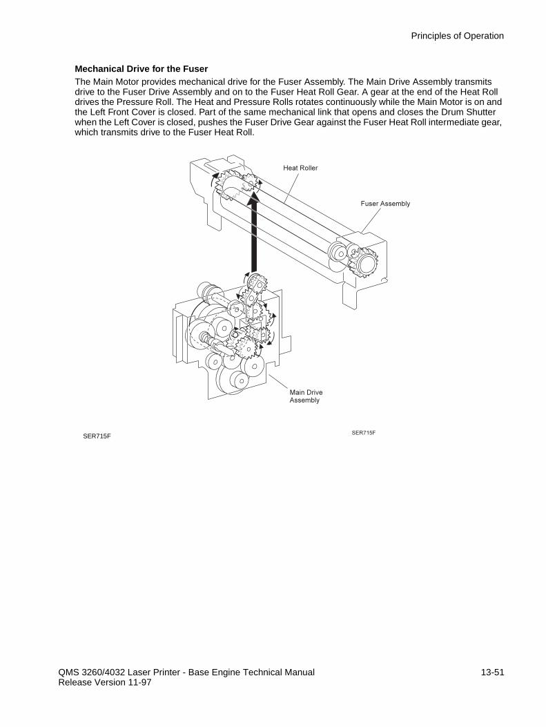
QMRe
Principles of Operation
Mechanical Drive for the FuserThe Main Motor provides mechanical drive for the Fuser Assembly. The Main Drive Assembly transmits drive to the Fuser Drive Assembly and on to the Fuser Heat Roll Gear. A gear at the end of the Heat Roll drives the Pressure Roll. The Heat and Pressure Rolls rotates continuously while the Main Motor is on and the Left Front Cover is closed. Part of the same mechanical link that opens and closes the Drum Shutter when the Left Cover is closed, pushes the Fuser Drive Gear against the Fuser Heat Roll intermediate gear, which transmits drive to the Fuser Heat Roll.
SER715F
S 3260/4032 Laser Printer - Base Engine Technical Manual 13-51lease Version 11-97

13
Principles of Operation
Mechanical Drive for Exit DriveThe Main Motor provides mechanical drive for the Offset and Exit Rolls. The Main Drive Assembly trans-mits drive to the Inverter CW Clutch and to the Inverter CCW Clutch. At a specific point in the print cyclethe MCU switches on the CW Clutch. The CW Clutch transmits forward drive to the Offset Roll, whichdrives the sheet of paper into the Face Down Output Tray. If the printer is running in Duplex Mode, at a spe-cific point in the forward drive, the MCU switches off the CW Clutch and switches on the CCW Clutch. TheCCW Clutch transmits reverse drive to the Offset Roll and to the Exit Roll, which drive the paper backacross the top of the Fuser Assembly and into the Duplex Module.
SER723FA
-52 QMS 3260/4032 Laser Printer - Base Engine Technical Manual Release Version 11-97

QMRe
Principles of Operation
Mechanical Drive for OffsetThe Offset Motor provides mechanical drive for the Offset Rolls. The Offset Motor transmits drive to theOffset Bracket. If the printer is running in Offset mode, the MCU switches on the Offset Motor. The Motordrives the Offset Bracket toward the front of the printer. The Bracket pushes the Offset Roll along with it.The Offset Rolls drive one sheet of paper into the Face Down Output Tray. The MCU switches the OffsetMotor on again, and the Motor drives the Offset Bracket back to the rear of the printer, taking the OffsetRoll with it. The Offset Rolls drive the next sheet of paper, slightly offset from the last sheet, into the FaceDown Output Tray.
SER716FA
S 3260/4032 Laser Printer - Base Engine Technical Manual 13-53lease Version 11-97
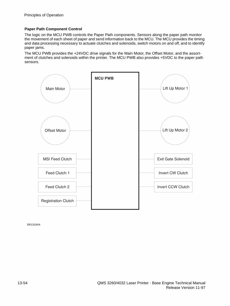
13
Principles of Operation
Paper Path Component Control
The logic on the MCU PWB controls the Paper Path components. Sensors along the paper path monitor the movement of each sheet of paper and send information back to the MCU. The MCU provides the timing and data processing necessary to actuate clutches and solenoids, switch motors on and off, and to identify paper jams.
The MCU PWB provides the +24VDC drive signals for the Main Motor, the Offset Motor, and the assort-ment of clutches and solenoids within the printer. The MCU PWB also provides +5VDC to the paper path sensors.
SR1319XA
-54 QMS 3260/4032 Laser Printer - Base Engine Technical Manual Release Version 11-97

QMRe
Principles of Operation
5 - The ROSThe ROS (Raster Output Scanner) is the mechanism that carries out Step 2. Expose of the print cycle.
A semiconductor within the ROS Assembly generates a beam of laser light. Image data received from theprint controller modulates this beam, turning it on and off according to image information that is receivedfrom the host computer.
Through the use of a series of rotating and stationary mirrors within the ROS, the beam sweeps the nega-tive charged drum surface. Whenever the print controller sends a command to print a black pixel, the laserswitches on long enough to shine onto the drum at a single pixel point. That point on the drum is now dis-charged. You will learn more about this process in 6- Xerographics.
SR1320X
SR1321X
S 3260/4032 Laser Printer - Base Engine Technical Manual 13-55lease Version 11-97

13
Principles of Operation
ROS Components The QMS 3260/4032 ROS Assembly is made up of one major component housing a number of sub-com-ponents.
The ROS generates a laser beam. The laser beam is a very powerful and narrowbeam of light that produces extreme heat at its focal point. The laser beam in theQMS 3260/4032 printer is invisible. Although you cannot see the beam, it can stillcause severe eye injury. Direct eye exposure to the laser beam may cause blind-ness. Never place a mirror or a reflective tool or object in the laser beam path. Neverrun the printer with the covers removed or the ROS interlocks bypassed.
Housed inside the ROS Assembly:
1. Laser Diode Assembly (LD)
A semiconductor Laser Diode that generates a 5 milliwatt class 3B laser beam. Circuity on the LD PWBmaintains the laser output power at a constant level. The LD PWB is electrically connected to the MCUPWB and to the ESS Mother PWB. The MCU provides power and control circuitry. The ESS MotherPWB provides the video data input from the host computer
2. Corrective Lenses and Angled Mirror
Four lenses, two small, one medium, and one wide, and an angled mirror focus the laser beam anddirect it toward the Polygon Mirror.
3. Polygon Mirror
A twelve-side rotating mirror that is attached to the Scanner Motor Assembly. The movement of therotating Polygon Mirror reflects the laser beam in a sweeping motion, from side to side across andthrough the wide lens.
4. Scanner Motor Assembly
The Scanner Motor Assembly is attached to the Scanner Motor Assembly PWB. The +24VDC Motorrotates at a constant speed. The Scanner Motor Assembly is electrically connected to the MCU.
5. Wide Lens
A lens that focuses the beam coming from the Polygon Mirror and directs it onto the Angled Mirror.
6. Drum Mirror
Angled so it reflects the laser beam coming from the Angled Mirror, down onto the surface of the drum.
7. SOS PWB (Start Of Scan Sensor)
The SOS Sensor is in-line with the laser beam sweep. The laser beam strikes the SOS Sensor at thebeginning of each sweep to let the printer control circuity know that a new scan has started. The SOSPWB is electrically connected to the MCU PWB.
-56 QMS 3260/4032 Laser Printer - Base Engine Technical Manual Release Version 11-97

QMRe
Principles of Operation
ROS Operation
The MCU PWB supplies +5VDC to drive the Laser Diode semiconductor. The semiconductor uses the+5VDC to generate a 5 milliwatt beam of invisible laser light.
As is characteristic of semiconductor devices, the Laser Diode can switch states very rapidly. A switchingcircuit on the Laser Diode PWB switches the Laser Diode on and off according to image data sent from theESS Mother PWB.
Two lenses, an angled mirror, and another two lenses focus the laser beam onto the rotating Polygon Mir-ror. The Polygon Mirror has twelve mirrored sides and rotates at approximately 15,000 RPM. The PolygonMirror reflects the laser beam back through the two lenses and onto the Angled Mirror. The movement ofthe Polygon Mirror reflects the laser beam in a sweeping motion, from side to side, across the Angled Mir-ror; with one complete sweep for each mirrored side.
The Angled Mirror reflects the laser beam onto the Drum Mirror. The Drum Mirror is aligned at an angle sothe mirror reflects the sweeping beam down onto the surface of the Drum. The combination of the rapidsweeping of the laser beam across the surface of the charged Drum and the rapid switching on and off ofthe laser beam creates, on the Drum, an invisible electrical image that corresponds to the screen imagethat was sent from the host computer. Located at one corner of the ROS, near the end of the Angled Mirroris the Start of Scan Sensor (SOS) Mirror. The Start of Scan Sensor is located at the opposite corner of theROS Assembly. Each sweep of the laser beam begins by striking the SOS Mirror, reflecting the beam intothe SOS Lens, which focuses the beam onto the SOS Sensor. The SOS Sensor is electrically connected tothe MCU PWB. When the laser beam strikes the Sensor, the Sensor notifies the MCU that a new scan hasstarted.
SR1323X
S 3260/4032 Laser Printer - Base Engine Technical Manual 13-57lease Version 11-97

13
Principles of Operation
Image Resolution
The QMS 3260/4032 printer has an print image resolution of 600 dpi (dots per inch). Print image resolutionis determined by the number of dots (or pixels) per inch of beam sweep and the number of sweeps per inchof paper travel.
SR1324X
-58 QMS 3260/4032 Laser Printer - Base Engine Technical Manual Release Version 11-97

QMRe
Principles of Operation
ROS Control
The Laser Diode PWB controls laser power monitoring and adjustment. The MCU PWB controls the rest ofthe ROS Assembly functions. The QMS Video Controller processes video data sent from a host computer.The QMS Video Controller then passes that data on to the ESS Mother PWB which controls the flow ofvideo data to the Laser Diode PWB. The ESS Mother PWB switches the laser diode on and off accordingto the image data being sent from the QMS Video Controller. When the data signals for a black pixel, theESS Mother PWB rapidly switches the Laser Diode on and off.
The MCU PWB provides the +5VDC needed to drive the Laser Diode. The CRU Interlock Switch cuts+5VDC to the Laser Diode when the EP Cartridge is not in place in the printer. The MCU PWB providesthe +24VDC needed to run the ROS Motor. The MCU PWB also provides the signal (/RMOT ON) thatswitches the ROS Motor on and off. To reduce ROS Motor wear, the MCU switches off the ROS Motor after15 minutes of printer inactivity.
The MCU PWB provides the +5VDC (signal 5V) needed by the SOS Sensor. The Sensor returns informa-tion about the start of each scan to the MCU through the /SOS signal.
SR1325XA
S 3260/4032 Laser Printer - Base Engine Technical Manual 13-59lease Version 11-97

13
Principles of Operation
Laser Hazards
Lasers generate a very powerful beam of light that produces extreme heat at its focal point. The laserbeam that the QMS 3260/4032 ROS generates is invisible. Although you cannot see the laser beam, directeye contact with the beam will cause serious eye injury.
Always follow the laser service rules and use good judgement when working on theQMS 3260/4032 printer.
ROS Safeguards
There are two safety interlocks built into the CRU cavity.
A molded tab located at the end of the EP Cartridge actuates Interlock SW1 which, along with SW2(the Left Cover Interlock), controls +24VDC out of the MCU PWB. When the Left Cover is open or theEP Cartridge is removed, SW1 and SW2 cut +24VDC out of the MCU PWB.
An electrical jack at the end of the EP Cartridge completes the +5VDC circuit for CRU Interlockswitches SW1 and SW2. When the EP Cartridge is removed, +5VDC to the Laser Diode is cut.
Never run the printer with the covers open or removed, the Main Interlock Switchactuated, and the CRU Interlock Switches bypassed. Direct eye exposure to thelaser beam may cause serious eye injury or blindness.
-60 QMS 3260/4032 Laser Printer - Base Engine Technical Manual Release Version 11-97

QMRe
Principles of Operation
6 - Xerographics
Xerographics and the Print CycleXerographics within the QMS 3260/4032 printer is represented by steps 1 through 5, and steps 7 and 8 ofthe print cycle.
The seven Xerographic steps (Step 6 Fuse is not part of the Xerographic cycle) in the print cycle are:
1. ChargePlaces a uniform negative electrostatic charge on the surface of the drum.
2. ExposeA data modulated laser beam scans the drum surface, converting select negative points to positivepoints.
3. DevelopAttaches dry toner to the positive points of the drum.
4. TransferTransfers the dry toner image from the drum to a piece of paper.
5. DetackStrips the piece of paper, along with the dry toner image on the paper surface, from the drum.
6. Clean
Cleans any residual toner from the surface of the drum and prepares the drum for the next print cycle.
7. DischargeCleans any residual electrical charge from the surface of the drum and prepares the drum for the nextprint cycle.
SR1326X
S 3260/4032 Laser Printer - Base Engine Technical Manual 13-61lease Version 11-97

13
Principles of Operation
An Overview of Xerographics
Xerography is the process of using an electrically charged surface and a dry, powered ink to create animage on a sheet of plain paper. Xerography, in some form, is used in most of today’s copiers and laserprinters. The QMS 3260/4032 printer uses a number of components and AC and DC voltages in its xero-graphic process.
The surface of the Drum is made of a photoconductive material that retains an electrical charge as long asthe material is not exposed to light. Exposure to light discharges the electrical charge. At the start of eachprint cycle the BCR (Bias Charge Roll) places a uniform electrical charge on the surface of the Drum. Themodulated Laser Beam shines light onto the surface of the drum, discharging select areas, thus creatingan invisible latent image. The latent image is made up of a pattern of negative and positive charges. TheMagnet Roll applies dry toner to the latent image to create a visible developed image . A sheet of paperpasses between the Drum and the BTR (Bias Transfer Roll) where the developed image on the drum istransferred to the paper. The DTS (Detack Saw) applies a voltage to the back of the paper to remove itfrom the Drum. The sheet of paper, now with a toner image on the surface, moves out of the Xerographicarea and on to the Fuser. The Cleaning Blade scrapes any residual toner left on the Drum after transferand deposits it in a sealed reservoir that is located inside the EP Cartridge.
SR1327X
-62 QMS 3260/4032 Laser Printer - Base Engine Technical Manual Release Version 11-97

QMRe
Principles of Operation
Xerographic ComponentsXerographics in the QMS 3260/4032 printer is made up of ten major components. Six of those componentsare housed inside the EP Cartridge. The EP Cartridge is a sealed unit that contains no field replaceableparts. The EP Cartridge is a CRU (Customer Replaceable Unit) with an estimated life of 23,000 prints;assuming 5% image coverage of a standard sheet of A4 paper.
Attached to the Transport Chute:
1. BTR (Bias Transfer Roll)
The BTR transfers the toner image from the drum to the sheet of paper. The BTR rotates during theprint cycle.
2. DTS (Detack Saw)
The DTS helps strip the sheet of paper off of the Drum.
Support components:
3. Toner Sensor
The Toner Sensor is a magnetic sensor that monitors the level of toner remaining inside the EP Car-tridge. The Toner Sensor is attached to the printer frame, inside the EP Cartridge cavity, and is electri-cally connected to the MCU PWB.
4. High Voltage Power Supply PWB
Supplies all of the voltages used by the Xerographic components.
S 3260/4032 Laser Printer - Base Engine Technical Manual 13-63lease Version 11-97

13
Principles of Operation
Housed inside the EP Cartridge:
5. Drum
The Drum is a hollow aluminum cylinder that has a surface coating of a photoconductive material. TheDrum rotates during the print cycle.
6. Bias Charge Roll (BCR)
The BCR places a uniform DC electrical charge on the surface of the drum. At the end of a print cycle,the BCR applies an AC voltage to the surface of the drum to neutralize any electrical patterns remain-ing from the previous print cycle. The BCR rotates during the print cycle.
7. Magnet Roll
The Magnet Roll collects toner from the toner reservoir and distributes it to the drum. The Magnet Rollrotates during the print cycle.
8. Charge Metal Blade (CM Blade)
The CM Blade spreads an even coating of toner across the Magnet Roll. The CM Blade also gives theRoll a static–electric charge.
9. Cleaning Blade
The Cleaning Blade rides the surface of the rotating drum, removing any residual toner left from theprevious print cycle.
10. Drum Shutter
The Drum Shutter protects the drum from damage by light or contamination. When the EP Cartridge isin the printer and the Left Upper Cover is closed, the Drum Shutter opens to expose the drum surface.When the EP Cartridge is out of the printer or the Left Upper Cover is open, the Drum Shutter closes.
SR1353X
-64 QMS 3260/4032 Laser Printer - Base Engine Technical Manual Release Version 11-97

QMRe
Principles of Operation
The Xerographic Process During a Print Cycle
1. Charge
The Bias Charge Roll (BCR) places a uniform negative electrostatic charge on the surface of the drum.The drum surface is made of a photoconductive material that holds an electrical charge as long as thedrum remains in darkness. Light striking the drum discharges the surface charge.The BCR is a conductive roll that is positioned slightly above the surface of the drum. The HVPS suppliesthe BCR with two voltages; a negative DC charge voltage and an AC discharge voltage that is used forelectrically cleaning the drum (discussed in Step 7. Clean).
SR1328XA
S 3260/4032 Laser Printer - Base Engine Technical Manual 13-65lease Version 11-97

13
Principles of Operation
2. Expose
The Raster Output Scanner (ROS) generates a beam of laser light. Image data received from the printcontroller modulates this beam, turning it on and off according to image information that is received fromthe host computer and software.Through the use of a series of rotating and stationary mirrors within the ROS, the beam scans the negativecharged drum surface. Whenever the print controller sends a command to print a black pixel, the laserswitches on long enough to shine onto the drum at a single pixel point. That point is now discharged andslightly less negative than the surrounding negative charge. For the sake of simplicity, the less negativeareas are considered "positive". This discharge/no discharge process creates an invisible, electrostaticimage on the surface of the drum. This image is called a latent image.The ROS also helps to clean and prepare the drum by scanning the surface of the drum at the beginning ofeach individual printer cycle. This action discharges an residual DC charge that may still remain on theDrum from the last print cycle.
SR1329X
-66 QMS 3260/4032 Laser Printer - Base Engine Technical Manual Release Version 11-97

QMRe
Principles of Operation
3. Develop
The toner contained within the EP Cartridge has a slight magnetic property that causes it to adhere to theMagnetic Roll. The Charge Metering Blade (CM Blade) spreads the toner into a very thin layer on the Mag-netic Roll. Friction between the Magnetic Roll and the CM Blade generates a small electrical charge that istransferred to the toner.The surface of the Magnetic Roll is made up of a thin sheet of conductive material. The HVPS supplies theMagnetic Roll with two voltages; a DC voltage and an AC voltage. The DC voltage is used to transfer tonerfrom the Magnetic Roll to the surface of the drum. The AC voltage agitates the toner on the Magnetic Roll,making toner transfer easier. The Magnetic Roll maintains a negative DC electrical potential. Negative charged areas of the drum have alower electrical potential, or higher relative negative value than the Magnetic Roll. Discharged areas of thedrum have a higher electrical potential, or lower relative negative value, than the Magnetic Roll. A dis-charged point on the surface of the drum now appears less negative, or positive, in relation to the negativecharge on the Magnetic Roll.The toner adhering to the Magnet Roll is always in contact with the drum surface. When a less negativepoint on the drum (a discharged area) comes in contact with the more negative charged toner on the Mag-net Roll, toner transfers from the Magnet Roll to that point on the drum. There is now a visible toner imageon the drum surface. The image is called a developed image.
SR1330XA
S 3260/4032 Laser Printer - Base Engine Technical Manual 13-67lease Version 11-97
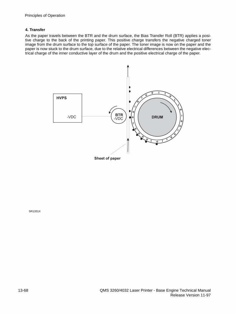
13
Principles of Operation
4. Transfer
As the paper travels between the BTR and the drum surface, the Bias Transfer Roll (BTR) applies a posi-tive charge to the back of the printing paper. This positive charge transfers the negative charged tonerimage from the drum surface to the top surface of the paper. The toner image is now on the paper and thepaper is now stuck to the drum surface, due to the relative electrical differences between the negative elec-trical charge of the inner conductive layer of the drum and the positive electrical charge of the paper.
SR1331X
-68 QMS 3260/4032 Laser Printer - Base Engine Technical Manual Release Version 11-97

QMRe
Principles of Operation
5. Detack
After the toner image transfers to the surface of the paper, the Detack Saw (a thin strip of metal that resem-bles a saw blade) applies a low voltage negative charge to the back of the paper to neutralize the positivevoltage that was applied to it by the BTR. Once the positive voltage is neutralized, the paper strips releaseseasily from the drum surface and continues along the paper path to the Fuser.
SR1332X
S 3260/4032 Laser Printer - Base Engine Technical Manual 13-69lease Version 11-97

13
Principles of Operation
7. Clean
The Cleaning Blade removes any toner that remains on the drum after the transfer process. The toner thatthe Cleaning Blade removes is collected inside the sealed EP Cartridge. Toner that is reclaimed from thedrum is not reused by the EP Cartridge.
SR1334X
-70 QMS 3260/4032 Laser Printer - Base Engine Technical Manual Release Version 11-97
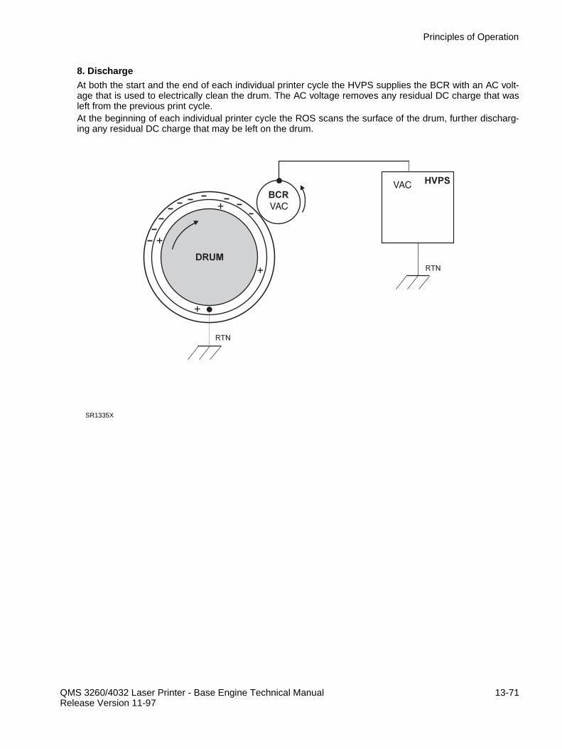
QMRe
Principles of Operation
8. Discharge
At both the start and the end of each individual printer cycle the HVPS supplies the BCR with an AC volt-age that is used to electrically clean the drum. The AC voltage removes any residual DC charge that wasleft from the previous print cycle.At the beginning of each individual printer cycle the ROS scans the surface of the drum, further discharg-ing any residual DC charge that may be left on the drum.
SR1335X
S 3260/4032 Laser Printer - Base Engine Technical Manual 13-71lease Version 11-97
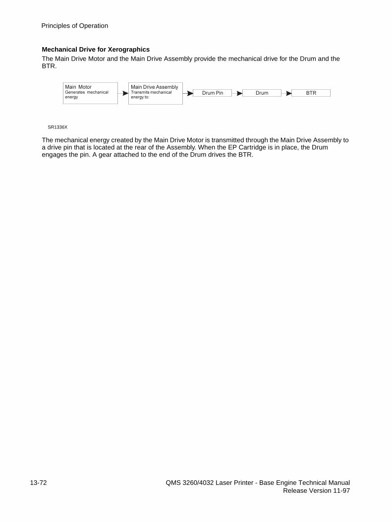
13
Principles of Operation
Mechanical Drive for XerographicsThe Main Drive Motor and the Main Drive Assembly provide the mechanical drive for the Drum and the BTR.
The mechanical energy created by the Main Drive Motor is transmitted through the Main Drive Assembly to a drive pin that is located at the rear of the Assembly. When the EP Cartridge is in place, the Drum engages the pin. A gear attached to the end of the Drum drives the BTR.
SR1336X
-72 QMS 3260/4032 Laser Printer - Base Engine Technical Manual Release Version 11-97

QMRe
Principles of Operation
Xerographic ControlThe logic on the MCU PWB controls all Xerographic functions. The High Voltage Power Supply (HVPS) provides all of the Xerographic voltages.
HVPSThe MCU PWB supplies +24VDC to the HVPS. The HVPS converts the +24VDC to the Xerographic volt-ages. The HVPS provides CR (Charge Voltages), DB (Developer Bias Voltages), TR (Transfer Voltage),DTS (Detack Saw Voltage), and RTN (Return). The logic on the MCU PWB uses a number of signals to theHVPS to switch on the various Xerographic components.
Toner Sensor
The Toner Sensor is electrically connected to the MCU PWB through P/J127. The logic on the MCU PWBuses the NO TONER signal to monitor the level of unused toner inside the EP Cartridge. When the NOTONER signal goes low, the MCU PWB logic waits for ten additional print cycles to complete, then it gener-ates a J6-1: Replace the EP Cartridge error message.
SR1337XA
S 3260/4032 Laser Printer - Base Engine Technical Manual 13-73lease Version 11-97
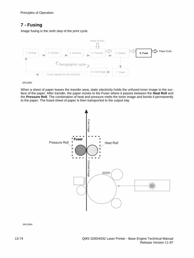
13
Principles of Operation
7 - FusingImage fusing is the sixth step of the print cycle.
When a sheet of paper leaves the transfer area, static electricity holds the unfused toner image to the sur-face of the paper. After transfer, the paper moves to the Fuser where it passes between the Heat Roll andthe Pressure Roll . The combination of heat and pressure melts the toner image and bonds it permanentlyto the paper. The fused sheet of paper is then transported to the output tray.
SR1338X
SR1339X
-74 QMS 3260/4032 Laser Printer - Base Engine Technical Manual Release Version 11-97
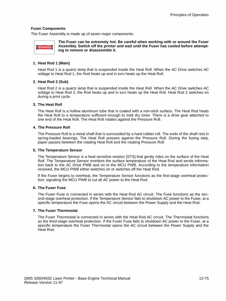
QMRe
Principles of Operation
Fuser ComponentsThe Fuser Assembly is made up of seven major components:
The Fuser can be extremely hot. Be careful when working with or around the FuserAssembly. Switch off the printer and wait until the Fuser has cooled before attempt-ing to remove or disassemble it.
1. Heat Rod 1 (Main)
Heat Rod 1 is a quartz lamp that is suspended inside the Heat Roll. When the AC Drive switches ACvoltage to Heat Rod 1, the Rod heats up and in turn heats up the Heat Roll.
2. Heat Rod 2 (Sub)
Heat Rod 2 is a quartz lamp that is suspended inside the Heat Roll. When the AC Drive switches ACvoltage to Heat Rod 2, the Rod heats up and in turn heats up the Heat Roll. Heat Rod 2 switches onduring a print cycle.
3. The Heat Roll
The Heat Roll is a hollow aluminum tube that is coated with a non-stick surface. The Heat Rod heatsthe Heat Roll to a temperature sufficient enough to melt dry toner. There is a drive gear attached toone end of the Heat Roll. The Heat Roll rotates against the Pressure Roll.
4. The Pressure Roll
The Pressure Roll is a metal shaft that is surrounded by a hard rubber roll. The ends of the shaft rest inspring-loaded bearings. The Heat Roll presses against the Pressure Roll. During the fusing step,paper passes between the rotating Heat Roll and the rotating Pressure Roll.
5. The Temperature Sensor
The Temperature Sensor is a heat sensitive resistor [STS] that gently rides on the surface of the HeatRoll. The Temperature Sensor monitors the surface temperature of the Heat Rod and sends informa-tion back to the AC Drive PWB and on to the MCU PWB. According to the temperature informationreceived, the MCU PWB either switches on or switches off the Heat Rod.
If the Fuser begins to overheat, the Temperature Sensor functions as the first-stage overheat protec-tion; signaling the MCU PWB to cut all AC power to the Heat Rod.
6. The Fuser Fuse
The Fuser Fuse is connected in series with the Heat Rod AC circuit. The Fuse functions as the sec-ond-stage overheat protection. If the Temperature Sensor fails to shutdown AC power to the Fuser, at aspecific temperature the Fuse opens the AC circuit between the Power Supply and the Heat Rod.
7. The Fuser Thermostat
The Fuser Thermostat is connected in series with the Heat Rod AC circuit. The Thermostat functionsas the third-stage overheat protection. If the Fuser Fuse fails to shutdown AC power to the Fuser, at aspecific temperature the Fuser Thermostat opens the AC circuit between the Power Supply and theHeat Rod.
S 3260/4032 Laser Printer - Base Engine Technical Manual 13-75lease Version 11-97

13
Principles of Operation
Mechanical Drive for the Fuser AssemblyThe Main Drive Motor, the Main Drive Assembly, and the Fuser Drive Assembly provide the mechanical drive for the Fuser Assembly.
The Main Drive Assembly transmits drive to the Fuser Drive Gear.
SR1340X
SER715F
-76 QMS 3260/4032 Laser Printer - Base Engine Technical Manual Release Version 11-97

QMRe
Principles of Operation
When the Left Upper Cover is closed, the DTS Link Rod pushes the Fuser Drive Assembly into contact with the Fuser Drive Gear, which transmits drive to the Heat Roll Gear. The Heat Roll rotates and transmits drive through a Pressure Roll Gear to the Pressure Roll.
SER718F
S 3260/4032 Laser Printer - Base Engine Technical Manual 13-77lease Version 11-97
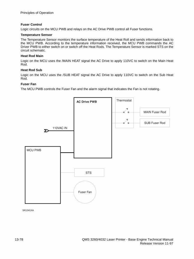
13
Principles of Operation
Fuser ControlLogic circuits on the MCU PWB and relays on the AC Drive PWB control all Fuser functions.
Temperature SensorThe Temperature Sensor monitors the surface temperature of the Heat Roll and sends information back tothe MCU PWB. According to the temperature information received, the MCU PWB commands the ACDriver PWB to either switch on or switch off the Heat Rods. The Temperature Sensor is marked STS on thecircuit schematic.
Heat Rod Main
Logic on the MCU uses the /MAIN HEAT signal the AC Drive to apply 110VC to switch on the Main HeatRod.
Heat Rod Sub
Logic on the MCU uses the /SUB HEAT signal the AC Drive to apply 110VC to switch on the Sub HeatRod.
Fuser Fan
The MCU PWB controls the Fuser Fan and the alarm signal that indicates the Fan is not rotating.
SR1341XA
-78 QMS 3260/4032 Laser Printer - Base Engine Technical Manual Release Version 11-97

QMS 3260/4032 Laser Printer - Base Engine Technical Manual 14-1Release Version 11-97
Wiring Diagrams and Signal Information
Section 14 - Wiring Diagrams and Signal Information Contents
Wiring Diagram Notations . . . . . . . . . . . . . . . . . . . . . . . . . . . . . . . . . . . . . . . . . . . . . . . . . . . . . . . . 14-2Master Wiring Diagram . . . . . . . . . . . . . . . . . . . . . . . . . . . . . . . . . . . . . . . . . . . . . . . . . . . . . . . . . . 14-3BD1 AC in ↔Noise Filter↔LVPS↔ESS Mother PWB↔AC Drive PWB↔D0 Console . . . . . . . . . . 14-4BD2 Console↔ESS Mother PWB . . . . . . . . . . . . . . . . . . . . . . . . . . . . . . . . . . . . . . . . . . . . . . . . . . 14-6BD3 ESS Mother PWB↔QMS Video Controller↔MCU PWB . . . . . . . . . . . . . . . . . . . . . . . . . . . . . 14-8BD4 ROS↔MCU PWB. . . . . . . . . . . . . . . . . . . . . . . . . . . . . . . . . . . . . . . . . . . . . . . . . . . . . . . . . . 14-10BD5 Toner Sensor↔Xerographic CRU↔MCU PWB . . . . . . . . . . . . . . . . . . . . . . . . . . . . . . . . . . . 14-12BD6 HVPS↔MCU PWB. . . . . . . . . . . . . . . . . . . . . . . . . . . . . . . . . . . . . . . . . . . . . . . . . . . . . . . . . 14-14BD7 Fuser Fan↔Main Motor↔Interlocks SM1 & SM2↔MCU PWB . . . . . . . . . . . . . . . . . . . . . . . 14-16BD8 Tray1↔MCU PWB-MSI↔MCU PWB-Envelope Feeder↔MCU PWB . . . . . . . . . . . . . . . . . . 14-18BD9 Size1 Sensor↔Registration Sensor↔No-Paper1 Sensor↔Level 1 Sensor↔MCU PWB. . . 14-20BD10 Miscellaneous Clutches and Sensors, Offset Motor, Exit Gate Solenoid↔MCU PWB . . . . 14-22BD11 Mailbox↔Finisher↔MCU PWB . . . . . . . . . . . . . . . . . . . . . . . . . . . . . . . . . . . . . . . . . . . . . . 14-24BD12 Duplex PWB↔MCU PWB . . . . . . . . . . . . . . . . . . . . . . . . . . . . . . . . . . . . . . . . . . . . . . . . . . 14-26BD13 Tray 2 Components↔MCU PWB . . . . . . . . . . . . . . . . . . . . . . . . . . . . . . . . . . . . . . . . . . . . . 14-28
This section of the manual contains a Master Wiring Diagram for the QMS 3260/4032 printer. TheMaster Wiring Diagram shows the interconnections of the major subsystems within the printer. Theremainder of this section divides the Master Wiring Diagram into thirteen individual block diagrams(BD) to better illustrate the electrical relationships between components and assemblies within theprinter. Each wire in the diagrams is tagged with a signal name, and each wire is terminated at bothends with a pin number.

14-2 QMS 3260/4032 Laser Printer - Base Engine Technical Manual Release Version 11-97
Wiring Diagrams and Signal Information
Wiring Diagram NotationsThe wiring diagrams presented in this manual use the following circuit notations to describe componentsand signal paths within the printer.
A PLUG
CONNECTION OF PIN 15 OF CONNECTORS P28AND J28.
THE VOLTAGE MEASURED WITH THE NEGATIVEPROBE OF THE METER ON SG
THE VOLTAGE VALUE OF A SIGNAL
/ = The voltage goes LOW when the signal is ON.
In this case, the HEAT signal is ON, so the normal volt-age of 4.2VDC drops to 0VDC.
A JACK
THE SIGNAL NAME OF A WIRE
SG SIGNAL GROUND
FG FRAME GROUND
RTN RETURN
There is continuity between SG and RTN. Con-tinuity between FG and SG depends on circuitspecifications.
$ $ in a signal name indicates the signal is com-ing from the MCU CPU.
# # in a signal name indicates the signal is goingto the MCU CPU.
TTL TTL displayed in the HIGH level or LOW levelcolumns of the signal tables indicate the signalis ECL_CMOS compatible.
HIGH is 4 to 5 VDC
LOW is 0 to 0.8 VDC
SR1400X

QMRe
Wiring Diagrams and Signal Information
Master Wiring Diagram
SER628XD
S 3260/4032 Laser Printer - Base Engine Technical Manual 14-3lease Version 11-97

14
Wiring Diagrams and Signal Information
BD1 AC in ↔Noise Filter ↔LVPS↔ESS Mother PWB ↔AC Drive PWB ↔D0 Console
SER601FA
-4 QMS 3260/4032 Laser Printer - Base Engine Technical Manual Release Version 11-97
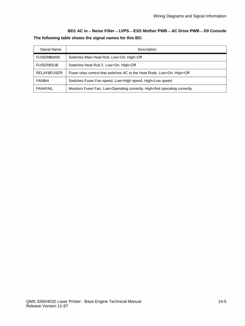
QMRe
Wiring Diagrams and Signal Information
BD1 AC in ↔Noise Filter ↔LVPS↔ESS Mother PWB ↔AC Drive PWB ↔D0 Console
The following table shows the signal names for this BD:
Signal Name Description
FUSER$MAIN Switches Main Heat Rod. Low=On. High=Off
FUSER$SUB Switches Heat Rod 2. Low=On. High=Off
RELAY$FUSER Fuser relay control that switches AC to the Heat Rods. Low=On. High=Off
FAN$HI Switches Fuser Fan speed. Low=High speed. High=Low speed
FAN#FAIL Monitors Fuser Fan. Low=Operating correctly. High=Not operating correctly.
S 3260/4032 Laser Printer - Base Engine Technical Manual 14-5lease Version 11-97
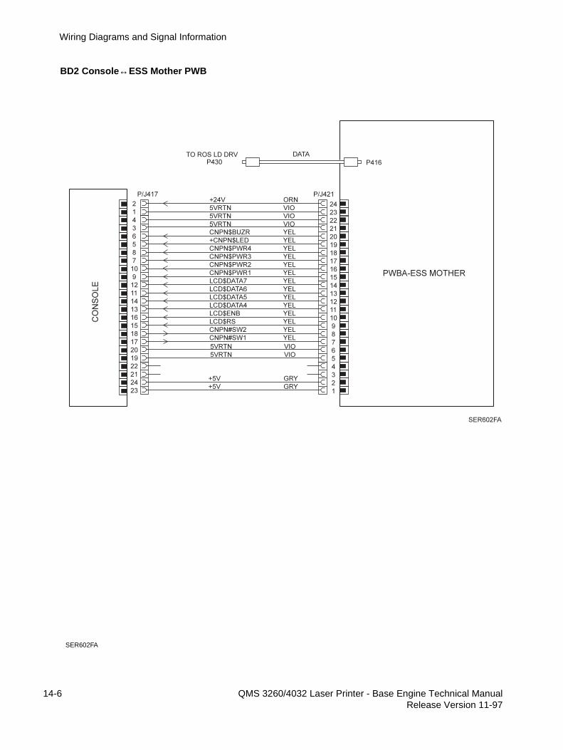
14
Wiring Diagrams and Signal Information
BD2 Console ↔ESS Mother PWB
SER602FA
-6 QMS 3260/4032 Laser Printer - Base Engine Technical Manual Release Version 11-97

QMRe
Wiring Diagrams and Signal Information
BD2 Console ↔ESS Mother PWB
The following table shows the signal names for this BD:
Signal Name Description
CNPN$BUZR Control Panel buzzer
+CNPN$LED LED synch. High=Off. Low=On
CNPN$PWR4 Key synch. High=Key pressed. Low=Key not pressed
CNPN$PWR3 Source for Key and LED. High=On. Low=Off
CNPN$PWR2 Source for Key and LED. High=On. Low=Off
CNPN$PWR1 Source for Key and LED. High=On. Low=Off
LCD$DATA7 Logic line for Controller LCD
LCD$DATA6 Logic line for Controller LCD
LCD$DATA5 Logic line for Controller LCD
LCD$DATA4 Logic line for Controller LCD
LCD$ENB LCD Controller write signal.
LCD$RS LCD Controller register select signal. High=Data register. Low=Instruction register
CNPN#SW1 Key synch. High=Key pressed. Low=Key not pressed
CNPN#SW2 Key synch. High=Key pressed. Low=Key not pressed
S 3260/4032 Laser Printer - Base Engine Technical Manual 14-7lease Version 11-97

14
Wiring Diagrams and Signal Information
BD3 ESS Mother PWB ↔QMS Video Controller ↔MCU PWB
SER603XB
-8 QMS 3260/4032 Laser Printer - Base Engine Technical Manual Release Version 11-97
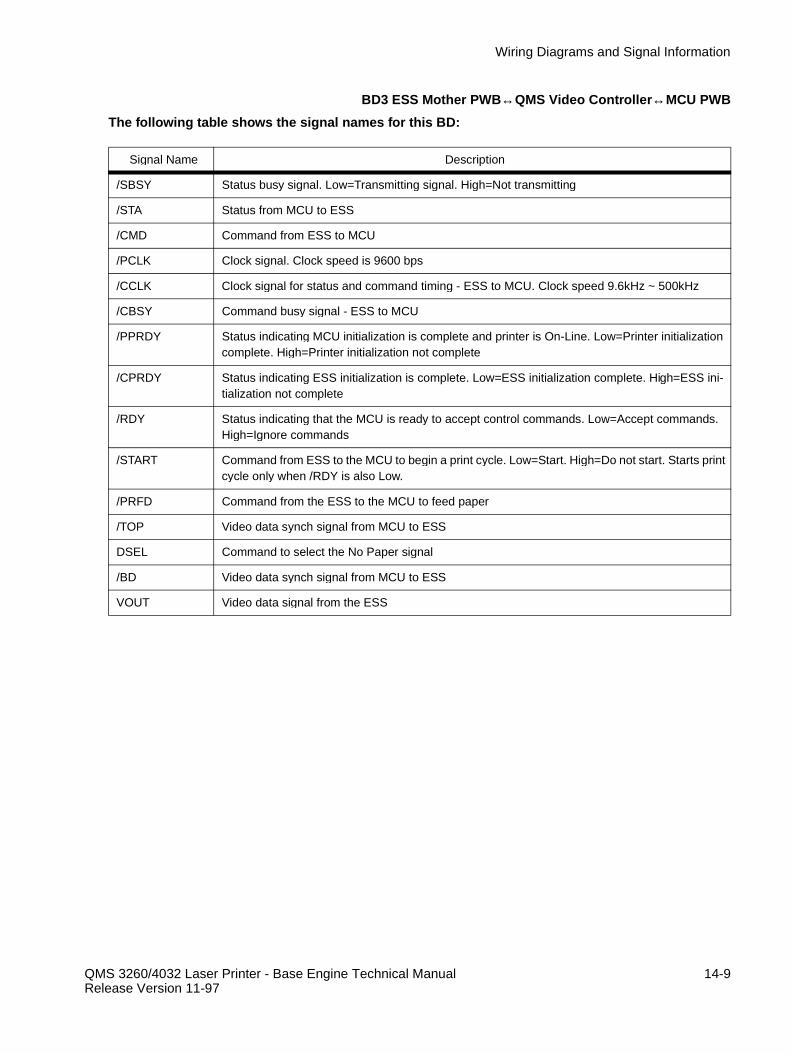
QMRe
Wiring Diagrams and Signal Information
BD3 ESS Mother PWB ↔QMS Video Controller ↔MCU PWB
The following table shows the signal names for this BD:
Signal Name Description
/SBSY Status busy signal. Low=Transmitting signal. High=Not transmitting
/STA Status from MCU to ESS
/CMD Command from ESS to MCU
/PCLK Clock signal. Clock speed is 9600 bps
/CCLK Clock signal for status and command timing - ESS to MCU. Clock speed 9.6kHz ~ 500kHz
/CBSY Command busy signal - ESS to MCU
/PPRDY Status indicating MCU initialization is complete and printer is On-Line. Low=Printer initialization complete. High=Printer initialization not complete
/CPRDY Status indicating ESS initialization is complete. Low=ESS initialization complete. High=ESS ini-tialization not complete
/RDY Status indicating that the MCU is ready to accept control commands. Low=Accept commands. High=Ignore commands
/START Command from ESS to the MCU to begin a print cycle. Low=Start. High=Do not start. Starts print cycle only when /RDY is also Low.
/PRFD Command from the ESS to the MCU to feed paper
/TOP Video data synch signal from MCU to ESS
DSEL Command to select the No Paper signal
/BD Video data synch signal from MCU to ESS
VOUT Video data signal from the ESS
S 3260/4032 Laser Printer - Base Engine Technical Manual 14-9lease Version 11-97

14
Wiring Diagrams and Signal Information
BD4 ROS↔MCU PWB
SER604FA
-10 QMS 3260/4032 Laser Printer - Base Engine Technical Manual Release Version 11-97

QMRe
Wiring Diagrams and Signal Information
BD4 ROS↔MCU PWB
The following table shows the signal names for this BD:
Signal Name Description
CRU#DET Monitors CRU presence. High=CRU installed. Low=CRU not installed
DA$DATA Data used to set laser
LD$ENB Enables laser - MCU to the LD Drive. High=No enabled. Low=Enabled
APC$CNT Monitors APC count
RMOT$ON Controls Scanner Motor. High=Off. Low=On
RMOT$SP1 Controls Scanner Motor speed. SP3-1 -010=Standby. SP3-1-110=480dpi. SP3-1-011=600dpi.
RMOT$SP2 Controls Scanner Motor speed. SP3-1 -010=Standby. SP3-1-110=480dpi. SP3-1-011=600dpi.
RMOT#RDY Monitors Scanner Motor speed. Low=Speed correct. High=Speed not correct.
ROS#SOS Monitors start of scan. High=Off. Low=On
S 3260/4032 Laser Printer - Base Engine Technical Manual 14-11lease Version 11-97

14
Wiring Diagrams and Signal Information
BD5 Toner Sensor ↔Xerographic CRU ↔MCU PWB
SER605FB
-12 QMS 3260/4032 Laser Printer - Base Engine Technical Manual Release Version 11-97
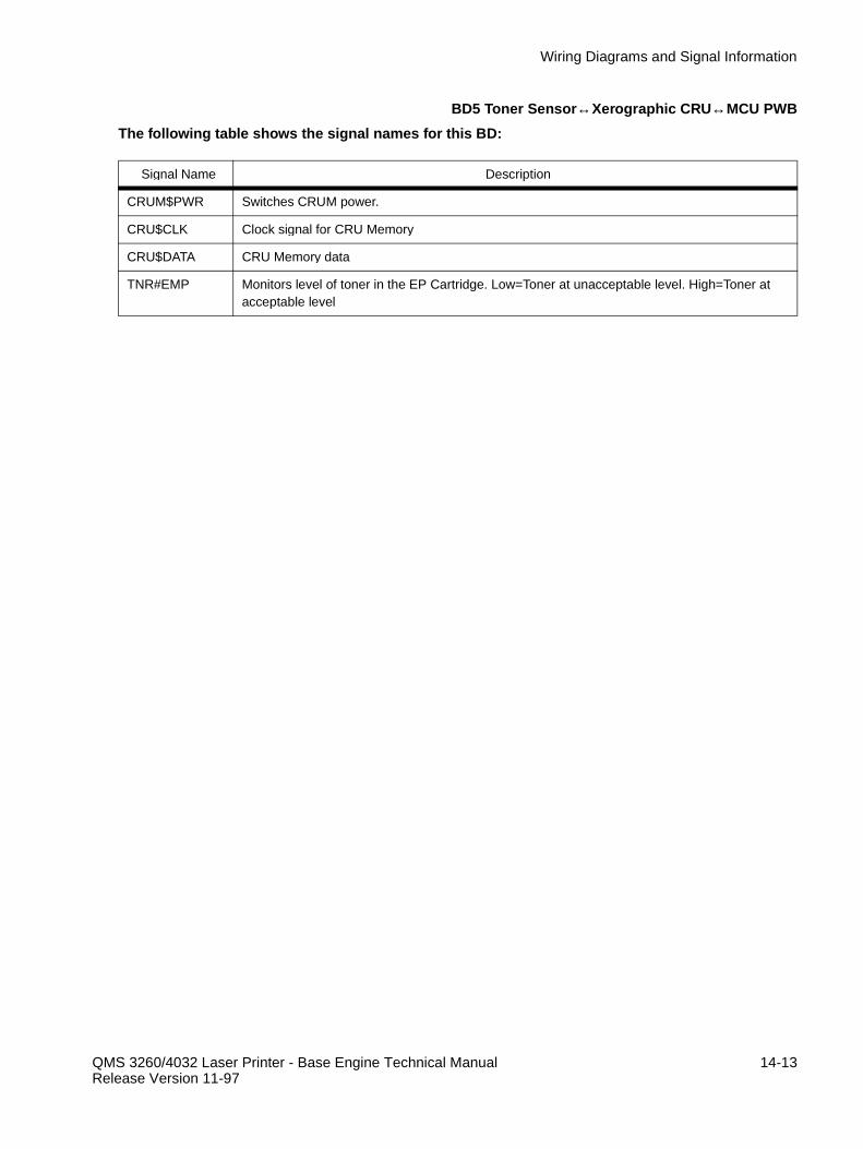
QMRe
Wiring Diagrams and Signal Information
BD5 Toner Sensor ↔Xerographic CRU ↔MCU PWB
The following table shows the signal names for this BD:
Signal Name Description
CRUM$PWR Switches CRUM power.
CRU$CLK Clock signal for CRU Memory
CRU$DATA CRU Memory data
TNR#EMP Monitors level of toner in the EP Cartridge. Low=Toner at unacceptable level. High=Toner at acceptable level
S 3260/4032 Laser Printer - Base Engine Technical Manual 14-13lease Version 11-97
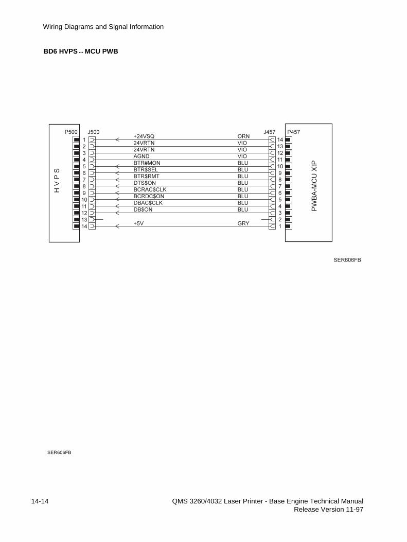
14
Wiring Diagrams and Signal Information
BD6 HVPS↔MCU PWB
SER606FB
-14 QMS 3260/4032 Laser Printer - Base Engine Technical Manual Release Version 11-97

QMRe
Wiring Diagrams and Signal Information
BD6 HVPS↔MCU PWB
The following table shows the signal names for this BD:
Signal Name Description
BTR#MON Monitors BTR current level
BTR$SEL Switches BTR voltage. High=Positive voltage. Low=Negative voltage
BTR$RMT Controls the current value to the BTR
DTS$ON Switches Detack Saw and Chute Bias voltage. High=Off. Low=On
BCRAC$CLK Controls the AC voltage value to the BCR. Negative logic
BCRDC$ON Switches BCR voltage. High=Off. Low=On
DBAC$CLK Controls the AC voltage value to the Magnet Roll. Negative logic
DB$ON Switches DB voltage. Negative logic
S 3260/4032 Laser Printer - Base Engine Technical Manual 14-15lease Version 11-97

14
Wiring Diagrams and Signal Information
BD7 Fuser Fan ↔Main Motor ↔Interlocks SM1 & SM2 ↔MCU PWB
SER607FB
-16 QMS 3260/4032 Laser Printer - Base Engine Technical Manual Release Version 11-97

QMRe
Wiring Diagrams and Signal Information
BD7 Fuser Fan ↔Main Motor ↔Interlocks SM1 & SM2 ↔MCU PWB
The following table shows the signal names for this BD:
Signal Name Description
MMOT$PWM Switches Main Motor. High=Off. Low=On.
MC#CLK Monitors the speed of the Main Motor.
FFAN$PWR Switches the Fuser Fan. High=On. Low =Off
FAN$LOW Switches the speed of the Fuser Fan. High=Low speed. Low=High speed
FUSER$FAIL Monitors the Fuser Fan. Low=Operation correct. High=Operation incorrect
INTLK#SW1 Monitors Left Cover interlock switch. High=Cover open. Low=Cover closed.
S 3260/4032 Laser Printer - Base Engine Technical Manual 14-17lease Version 11-97

14
Wiring Diagrams and Signal Information
BD8 TRAY1↔MCU PWB - MSI↔MCU PWB - ENVELOPE FEEDER↔MCU PWB
SER608XC
-18 QMS 3260/4032 Laser Printer - Base Engine Technical Manual Release Version 11-97

QMRe
Wiring Diagrams and Signal Information
BD8 TRAY1↔MCU PWB - MSI↔MCU PWB - ENVELOPE FEEDER↔MCU PWB
The following table shows the signal names for this BD:
Signal Name Description
SNR#SIZEM Analog signal from the MSI Size Sensor. Voltage levels 0VDC~5VDC
SNR#SIZE Analog signal from the Envelope Size Sensor. Voltage levels 0VDC~5VDC
SNR#NOPM Monitors level of paper in the MSI. High=No paper present. Low=Paper present
SNR#NOP Monitors level of paper in the Envelope Feeder
CL$FEEDM Controls MSI paper feed. High=No feed. Low=Feed
CL$FEED Controls Envelope feed. High=No feed. Low=Feed
MSI#DET Monitors presence of MSI. High=MSI not present. Low=MSI present
ENV#DET Monitors presence of Envelope Feeder. High=Envelope Feed not present. Low=Envelope Feeder present
EMOT$ON Switches Envelope Feed Motor. High=Off. Low=On
SNR#FEED Monitors paper between Envelope Feeder and base engine. High=Paper present Low=No paper
MOT$LIFT1(TTL) Switches Tray 1 Lift Up Motor. High=On. Low=Off
SNR#TAROL1 Monitors paper between Tray 2 and Tray 1. High=Paper present. Low=No paper
S 3260/4032 Laser Printer - Base Engine Technical Manual 14-19lease Version 11-97
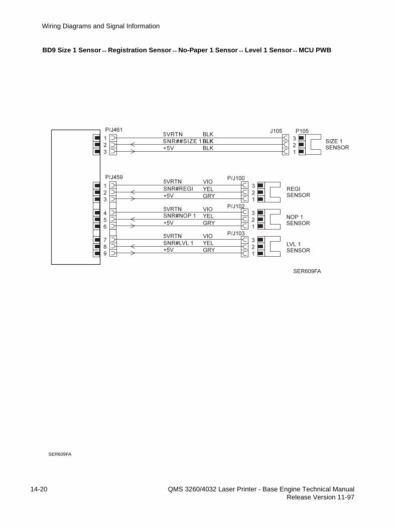
14
Wiring Diagrams and Signal Information
BD9 Size 1 Sensor ↔Registration Sensor ↔No-Paper 1 Sensor ↔Level 1 Sensor ↔MCU PWB
SER609FA
-20 QMS 3260/4032 Laser Printer - Base Engine Technical Manual Release Version 11-97
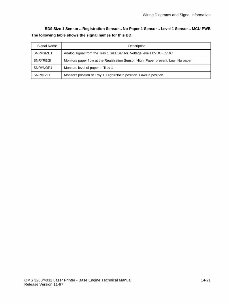
QMRe
Wiring Diagrams and Signal Information
BD9 Size 1 Sensor ↔Registration Sensor ↔No-Paper 1 Sensor ↔Level 1 Sensor ↔MCU PWB
The following table shows the signal names for this BD:
Signal Name Description
SNR#SIZE1 Analog signal from the Tray 1 Size Sensor. Voltage levels 0VDC~5VDC
SNR#REGI Monitors paper flow at the Registration Sensor. High=Paper present. Low=No paper
SNR#NOP1 Monitors level of paper in Tray 1
SNR#LVL1 Monitors position of Tray 1. High=Not in position. Low=In position
S 3260/4032 Laser Printer - Base Engine Technical Manual 14-21lease Version 11-97
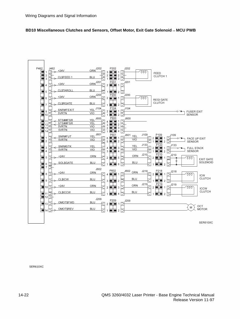
14
Wiring Diagrams and Signal Information
BD10 Miscellaneous Clutches and Sensors, Offset Motor, Exit Gate Solenoid ↔MCU PWB
SER610XC
-22 QMS 3260/4032 Laser Printer - Base Engine Technical Manual Release Version 11-97
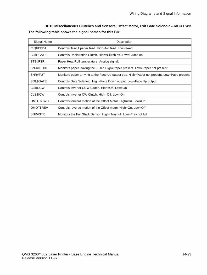
QMRe
Wiring Diagrams and Signal Information
BD10 Miscellaneous Clutches and Sensors, Offset Motor, Exit Gate Solenoid ↔MCU PWB
The following table shows the signal names for this BD:
Signal Name Description
CL$FEED1 Controls Tray 1 paper feed. High=No feed. Low=Feed
CL$RGATE Controls Registration Clutch. High=Clutch off. Low=Clutch on
STS#FSR Fuser Heat Roll temperature. Analog signal.
SNR#FEXIT Monitors paper leaving the Fuser. High=Paper present. Low=Paper not present
SNR#FUT Monitors paper arriving at the Face Up output tray. High=Paper not present. Low=Pape present
SOL$GATE Controls Gate Solenoid. High=Face Down output. Low=Face Up output.
CL$ICCW Controls Inverter CCW Clutch. High=Off. Low=On
CLS$ICW Controls Inverter CW Clutch. High=Off. Low=On
OMOT$FWD Controls forward motion of the Offset Motor. High=On. Low=Off
OMOT$REV Controls reverse motion of the Offset motor. High=On. Low=Off
SNR#STK Monitors the Full Stack Sensor. High=Tray full. Low=Tray not full
S 3260/4032 Laser Printer - Base Engine Technical Manual 14-23lease Version 11-97

14
Wiring Diagrams and Signal Information
BD11 Mailbox ↔Finisher ↔MCU PWB
SER611FA
-24 QMS 3260/4032 Laser Printer - Base Engine Technical Manual Release Version 11-97

QMRe
Wiring Diagrams and Signal Information
BD11 Mailbox ↔Finisher ↔MCU PWB
The following table shows the signal names for this BD:
Signal Name Description
OPT$TX+ Status of Finisher or Mailbox sent to MCU. High=Mark. Low=No mark
OPT#RX+ Status of MCU sent to the Finisher or Mailbox. High=Mark. Low=No mark
MBS#DET Monitors presence of Mailbox. High=Mailbox not installed. Low=Mailbox installed
FSNR#DET Monitors presence of Finisher. High=Finisher not installed. Low=Finisher installed
S 3260/4032 Laser Printer - Base Engine Technical Manual 14-25lease Version 11-97

14
Wiring Diagrams and Signal Information
BD12 Duplex PWB ↔MCU PWB
SER612XC
-26 QMS 3260/4032 Laser Printer - Base Engine Technical Manual Release Version 11-97
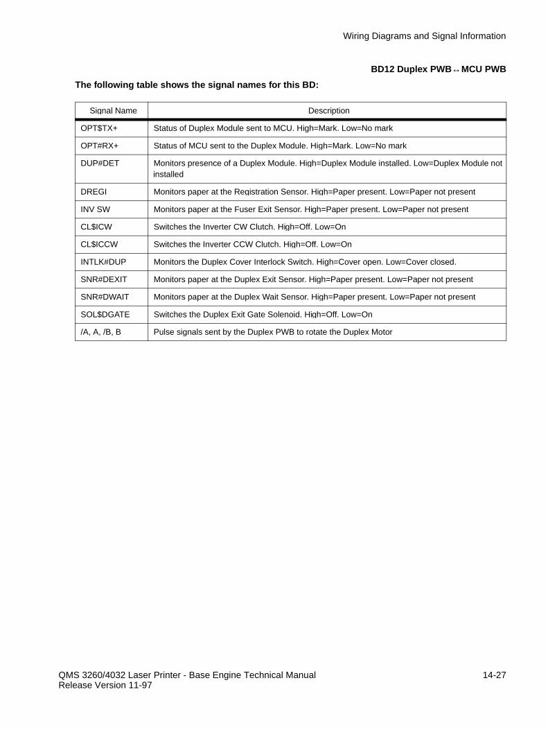
QMRe
Wiring Diagrams and Signal Information
BD12 Duplex PWB ↔MCU PWB
The following table shows the signal names for this BD:
Signal Name Description
OPT$TX+ Status of Duplex Module sent to MCU. High=Mark. Low=No mark
OPT#RX+ Status of MCU sent to the Duplex Module. High=Mark. Low=No mark
DUP#DET Monitors presence of a Duplex Module. High=Duplex Module installed. Low=Duplex Module not installed
DREGI Monitors paper at the Registration Sensor. High=Paper present. Low=Paper not present
INV SW Monitors paper at the Fuser Exit Sensor. High=Paper present. Low=Paper not present
CL$ICW Switches the Inverter CW Clutch. High=Off. Low=On
CL$ICCW Switches the Inverter CCW Clutch. High=Off. Low=On
INTLK#DUP Monitors the Duplex Cover Interlock Switch. High=Cover open. Low=Cover closed.
SNR#DEXIT Monitors paper at the Duplex Exit Sensor. High=Paper present. Low=Paper not present
SNR#DWAIT Monitors paper at the Duplex Wait Sensor. High=Paper present. Low=Paper not present
SOL$DGATE Switches the Duplex Exit Gate Solenoid. High=Off. Low=On
/A, A, /B, B Pulse signals sent by the Duplex PWB to rotate the Duplex Motor
S 3260/4032 Laser Printer - Base Engine Technical Manual 14-27lease Version 11-97

14
Wiring Diagrams and Signal Information
BD13 Tray 2 Components ↔MCU PWB
SER613XC
-28 QMS 3260/4032 Laser Printer - Base Engine Technical Manual Release Version 11-97
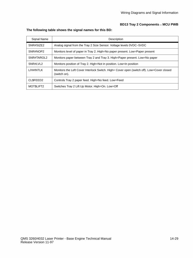
QMRe
Wiring Diagrams and Signal Information
BD13 Tray 2 Components ↔MCU PWB
The following table shows the signal names for this BD:
Signal Name Description
SNR#SIZE2 Analog signal from the Tray 2 Size Sensor. Voltage levels 0VDC~5VDC
SNR#NOP2 Monitors level of paper in Tray 2. High=No paper present. Low=Paper present
SNR#TAROL2 Monitors paper between Tray 2 and Tray 3. High=Paper present. Low=No paper
SNR#LVL2 Monitors position of Tray 2. High=Not in position. Low=In position
L/H#INTLK Monitors the Left Cover Interlock Switch. High= Cover open (switch off). Low=Cover closed (switch on).
CL$FEED2 Controls Tray 2 paper feed. High=No feed. Low=Feed
MOT$LIFT2 Switches Tray 2 Lift Up Motor. High=On. Low=Off
S 3260/4032 Laser Printer - Base Engine Technical Manual 14-29lease Version 11-97

14
Wiring Diagrams and Signal Information
Blank Page
-30 QMS 3260/4032 Laser Printer - Base Engine Technical Manual Release Version 11-97

QMRe
Printer Specifications
Section 15 - Printer Specifications Contents
General Specifications . . . . . . . . . . . . . . . . . . . . . . . . . . . . . . . . . . . . . . . . . . . . . . . . . . . . . . . . . . . 15-3Safety Standards . . . . . . . . . . . . . . . . . . . . . . . . . . . . . . . . . . . . . . . . . . . . . . . . . . . . . . . . . . . . . . . 15-5Printing Speed for First Sheet Out . . . . . . . . . . . . . . . . . . . . . . . . . . . . . . . . . . . . . . . . . . . . . . . . . . 15-6Continuous Printing Speed After the First Sheet Out . . . . . . . . . . . . . . . . . . . . . . . . . . . . . . . . . . . 15-7Paper Feeder & Supported Paper Specifications . . . . . . . . . . . . . . . . . . . . . . . . . . . . . . . . . . . . . . 15-8Paper Output Devices & Supported Paper Specifications . . . . . . . . . . . . . . . . . . . . . . . . . . . . . . . 15-10Printing Media Specifications for Use With QMS 3260/4032 . . . . . . . . . . . . . . . . . . . . . . . . . . . . . 15-11Recommended Paper for Feed from QMS 3260/4032 Universal Trays . . . . . . . . . . . . . . . . . . . . . 15-12Image Reproduction and Registration Specifications. . . . . . . . . . . . . . . . . . . . . . . . . . . . . . . . . . . 15-13Life Expectancy of Key Components . . . . . . . . . . . . . . . . . . . . . . . . . . . . . . . . . . . . . . . . . . . . . . . 15-14Printer Options . . . . . . . . . . . . . . . . . . . . . . . . . . . . . . . . . . . . . . . . . . . . . . . . . . . . . . . . . . . . . . . . 15-14
S 3260/4032 Laser Printer - Base Engine Technical Manual 15-1lease Version 11-97

15
Printer Specifications
Blank Page
-2 QMS 3260/4032 Laser Printer - Base Engine Technical ManualRelease Version 11-97
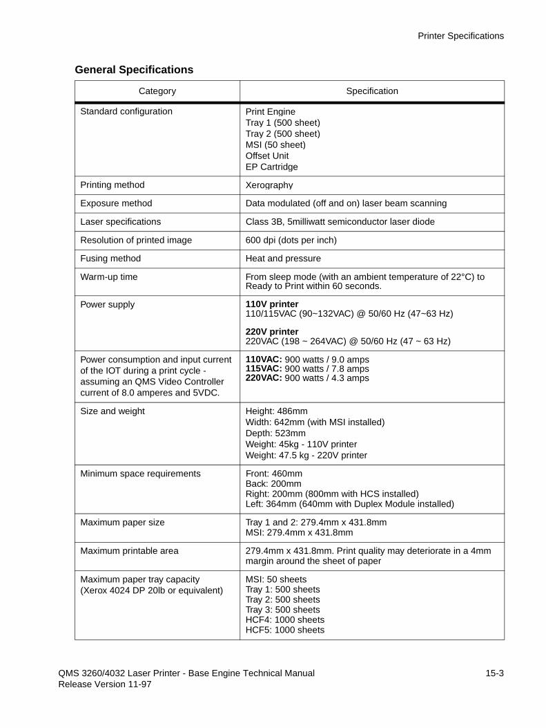
QMRe
Printer Specifications
General Specifications
Category Specification
Standard configuration Print EngineTray 1 (500 sheet)Tray 2 (500 sheet)MSI (50 sheet)Offset UnitEP Cartridge
Printing method Xerography
Exposure method Data modulated (off and on) laser beam scanning
Laser specifications Class 3B, 5milliwatt semiconductor laser diode
Resolution of printed image 600 dpi (dots per inch)
Fusing method Heat and pressure
Warm-up time From sleep mode (with an ambient temperature of 22°C) to Ready to Print within 60 seconds.
Power supply 110V printer110/115VAC (90~132VAC) @ 50/60 Hz (47~63 Hz)
220V printer220VAC (198 ~ 264VAC) @ 50/60 Hz (47 ~ 63 Hz)
Power consumption and input current of the IOT during a print cycle - assuming an QMS Video Controller current of 8.0 amperes and 5VDC.
110VAC: 900 watts / 9.0 amps115VAC: 900 watts / 7.8 amps220VAC: 900 watts / 4.3 amps
Size and weight Height: 486mmWidth: 642mm (with MSI installed)Depth: 523mmWeight: 45kg - 110V printerWeight: 47.5 kg - 220V printer
Minimum space requirements Front: 460mmBack: 200mmRight: 200mm (800mm with HCS installed)Left: 364mm (640mm with Duplex Module installed)
Maximum paper size Tray 1 and 2: 279.4mm x 431.8mmMSI: 279.4mm x 431.8mm
Maximum printable area 279.4mm x 431.8mm. Print quality may deteriorate in a 4mm margin around the sheet of paper
Maximum paper tray capacity(Xerox 4024 DP 20lb or equivalent)
MSI: 50 sheets Tray 1: 500 sheetsTray 2: 500 sheetsTray 3: 500 sheetsHCF4: 1000 sheetsHCF5: 1000 sheets
S 3260/4032 Laser Printer - Base Engine Technical Manual 15-3lease Version 11-97
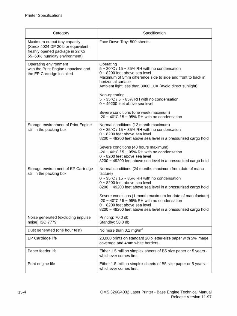
15
Printer Specifications
Maximum output tray capacity(Xerox 4024 DP 20lb or equivalent, freshly opened package in 22°C/55~60% humidity environment)
Face Down Tray: 500 sheets
Operating environmentwith the Print Engine unpacked and the EP Cartridge installed
Operating5 ~ 30°C / 15 ~ 85% RH with no condensation0 ~ 8200 feet above sea levelMaximum of 5mm difference side to side and front to back in horizontal surfaceAmbient light less than 3000 LUX (Avoid direct sunlight)
Non-operating5 ~ 35°C / 5 ~ 85% RH with no condensation0 ~ 49200 feet above sea level
Severe conditions (one week maximum)-20 ~ 40°C / 5 ~ 95% RH with no condensation
Storage environment of Print Engine still in the packing box
Normal conditions (12 month maximum)0 ~ 35°C / 15 ~ 85% RH with no condensation0 ~ 8200 feet above sea level8200 ~ 49200 feet above sea level in a pressurized cargo hold
Severe conditions (48 hours maximum)-20 ~ 40°C / 5 ~ 95% RH with no condensation0 ~ 8200 feet above sea level8200 ~ 49200 feet above sea level in a pressurized cargo hold
Storage environment of EP Cartridge still in the packing box
Normal conditions (24 months maximum from date of manu-facture)0 ~ 35°C / 15 ~ 85% RH with no condensation0 ~ 8200 feet above sea level8200 ~ 49200 feet above sea level in a pressurized cargo hold
Severe conditions (1 month maximum for date of manufacture)-20 ~ 40°C / 5 ~ 95% RH with no condensation0 ~ 8200 feet above sea level8200 ~ 49200 feet above sea level in a pressurized cargo hold
Noise generated (excluding impulse noise) ISO 7779
Printing: 70.0 dbStandby: 58.0 db
Dust generated (one hour test) No more than 0.1 mg/m3
EP Cartridge life 23,000 prints on standard 20lb letter-size paper with 5% image coverage and 4mm white borders.
Paper feeder life Either 1.5 million simplex sheets of B5 size paper or 5 years - whichever comes first.
Print engine life Either 1.5 million simplex sheets of B5 size paper or 5 years - whichever comes first.
Category Specification
-4 QMS 3260/4032 Laser Printer - Base Engine Technical ManualRelease Version 11-97
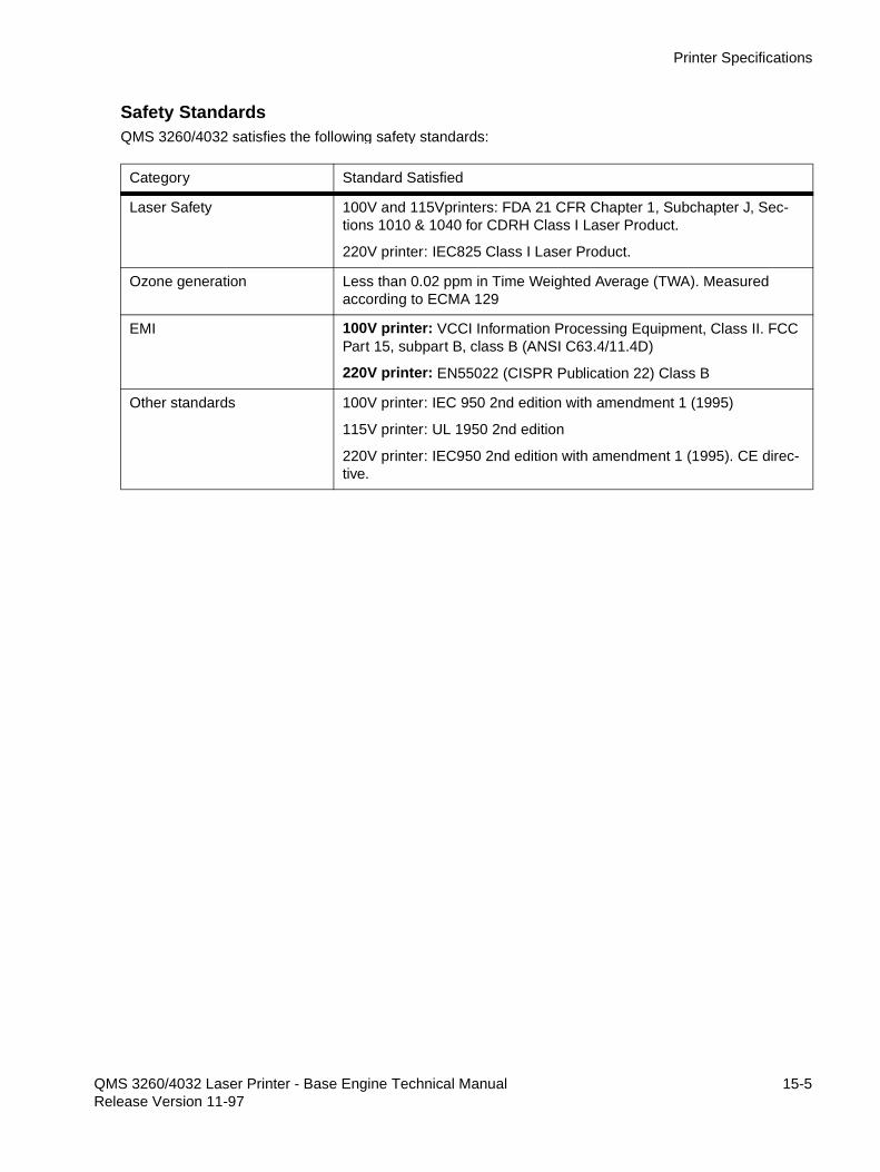
QMRe
Printer Specifications
Safety StandardsQMS 3260/4032 satisfies the following safety standards:
Category Standard Satisfied
Laser Safety 100V and 115Vprinters: FDA 21 CFR Chapter 1, Subchapter J, Sec-tions 1010 & 1040 for CDRH Class I Laser Product.
220V printer: IEC825 Class I Laser Product.
Ozone generation Less than 0.02 ppm in Time Weighted Average (TWA). Measured according to ECMA 129
EMI 100V printer: VCCI Information Processing Equipment, Class II. FCC Part 15, subpart B, class B (ANSI C63.4/11.4D)
220V printer: EN55022 (CISPR Publication 22) Class B
Other standards 100V printer: IEC 950 2nd edition with amendment 1 (1995)
115V printer: UL 1950 2nd edition
220V printer: IEC950 2nd edition with amendment 1 (1995). CE direc-tive.
S 3260/4032 Laser Printer - Base Engine Technical Manual 15-5lease Version 11-97
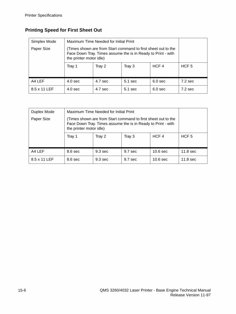
15
Printer Specifications
Printing Speed for First Sheet Out
Simplex Mode
Paper Size
Maximum Time Needed for Initial Print
(Times shown are from Start command to first sheet out to the Face Down Tray. Times assume the is in Ready to Print - with the printer motor idle)
Tray 1 Tray 2 Tray 3 HCF 4 HCF 5
A4 LEF 4.0 sec 4.7 sec 5.1 sec 6.0 sec 7.2 sec
8.5 x 11 LEF 4.0 sec 4.7 sec 5.1 sec 6.0 sec 7.2 sec
Duplex Mode
Paper Size
Maximum Time Needed for Initial Print
(Times shown are from Start command to first sheet out to the Face Down Tray. Times assume the is in Ready to Print - with the printer motor idle)
Tray 1 Tray 2 Tray 3 HCF 4 HCF 5
A4 LEF 8.6 sec 9.3 sec 9.7 sec 10.6 sec 11.8 sec
8.5 x 11 LEF 8.6 sec 9.3 sec 9.7 sec 10.6 sec 11.8 sec
-6 QMS 3260/4032 Laser Printer - Base Engine Technical ManualRelease Version 11-97
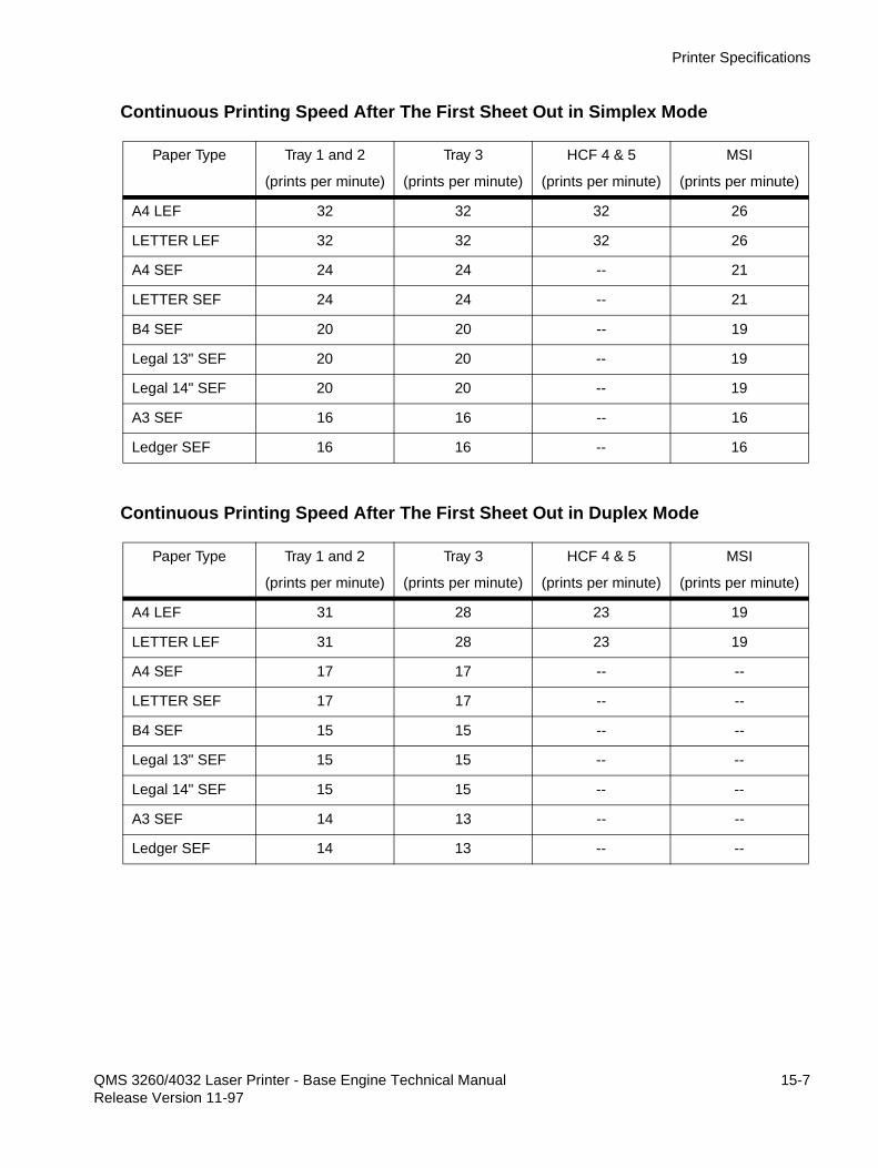
QMRe
Printer Specifications
Continuous Printing Speed After The First Sheet Out in Simplex Mode
Continuous Printing Speed After The First Sheet Out in Duplex Mode
Paper Type Tray 1 and 2
(prints per minute)
Tray 3
(prints per minute)
HCF 4 & 5
(prints per minute)
MSI
(prints per minute)
A4 LEF 32 32 32 26
LETTER LEF 32 32 32 26
A4 SEF 24 24 -- 21
LETTER SEF 24 24 -- 21
B4 SEF 20 20 -- 19
Legal 13" SEF 20 20 -- 19
Legal 14" SEF 20 20 -- 19
A3 SEF 16 16 -- 16
Ledger SEF 16 16 -- 16
Paper Type Tray 1 and 2
(prints per minute)
Tray 3
(prints per minute)
HCF 4 & 5
(prints per minute)
MSI
(prints per minute)
A4 LEF 31 28 23 19
LETTER LEF 31 28 23 19
A4 SEF 17 17 -- --
LETTER SEF 17 17 -- --
B4 SEF 15 15 -- --
Legal 13" SEF 15 15 -- --
Legal 14" SEF 15 15 -- --
A3 SEF 14 13 -- --
Ledger SEF 14 13 -- --
S 3260/4032 Laser Printer - Base Engine Technical Manual 15-7lease Version 11-97

15
Printer Specifications
Paper Feeder & Supported Paper Specifications The printer uses the following paper feeder/paper size combinations:
Trays 1 and 2 for the 500 Sheet Feeder (standard)
Standard feeder for the QMS 3260/4032 printer. Each tray has paper size automatic sensing. Trays 1 and2 can each hold up to 500 sheets (54mm stack height of 20lb paper) of the following paper.
High Capacity Feeder - Tray 3 (option)
Top HCF tray for the QMS 3260/4032 printer. Tray 3 has paper size automatic sensing. Tray 3 can hold upto 500 sheets (54mm stack height of 20lb paper) of the following paper.
Factory set Option 1 Factory set Option 2
Ledger SEF - 279.4mm x 431.8mm Ledger SEF - 279.4mm x 431.8mm
A3 SEF - 297mm x 420mm A3 SEF - 297mm x 420mm
B4 SEF - 257mm x 364mm Legal 14" SEF - 215.9mm x 355.6mm
Letter SEF LEF - 215.9mm x 279.4mm Letter SEF LEF - 215.9mm x 279.4mm
Legal 13" SEF - 215.9mm x 330.2mm Legal 13" SEF - 215.9mm x 330.2mm
A4 SEF LEF - 210mm x 297mm A4 SEF LEF - 210mm x 297mm
Executive LEF - 184.2mm x 266.7mm B5 LEF - 182mm x 257mm
A5 LEF - 149mm x 210mm A5 LEF - 149mm x 210mm
STATEMENT - 139.9mm x 215.9mm STATEMENT - 139.9mm x 215.9mm
Factory set Option 1 Factory set Option 2
Ledger SEF - 279.4mm x 431.8mm Ledger SEF - 279.4mm x 431.8mm
A3 SEF - 297mm x 420mm A3 SEF - 297mm x 420mm
B4 SEF - 257mm x 364mm Legal 14" SEF - 215.9mm x 355.6mm
Letter SEF LEF - 215.9mm x 279.4mm Letter SEF LEF - 215.9mm x 279.4mm
Legal 13" SEF - 215.9mm x 330.2mm Legal 13" SEF - 215.9mm x 330.2mm
A4 SEF LEF - 210mm x 297mm A4 SEF LEF - 210mm x 297mm
Executive LEF - 184.2mm x 266.7mm B5 LEF - 182mm x 257mm
-8 QMS 3260/4032 Laser Printer - Base Engine Technical ManualRelease Version 11-97

QMRe
Printer Specifications
High Capacity Feeder - Tray 4 and Tray 5 (option)
Optional feeder for the QMS 3260/4032 printer. Trays 4 and 5 can each hold up to 1000 sheets (54mmstack height of 20lb paper) of the following paper.
MSI (Multi Sheet Inserter) (standard)
Standard feeder for the QMS 3260/4032 printer. The MSI attaches to the left side of the printer. The MSIholds up to 50 sheets (5mm stack height of 64 ~ 105gsm paper or 190gsm postcard) of the followingpaper.
Envelope Feeder (option)
Optional Envelope feeder for the QMS 3260/4032 printer. Replaces the MSI. The Envelope Feeder has ano paper sensor. The Envelope Feeder can hold the following envelopes (maximum of 100 envelopesbetween 64 ~ ‘05gsm).
Factory set Option 1 Factory set Option 2
Letter SEF LEF - 215.9mm x 279.4mm Letter SEF LEF - 215.9mm x 279.4mm
A4 SEF LEF - 210mm x 297mm A4 SEF LEF - 210mm x 297mm
Executive LEF - 184.2mm x 266.7mm B5 LEF - 182mm x 257mm
Factory set Option 1 Factory set Option 2
Ledger SEF - 279.4mm x 431.8mm Ledger SEF - 279.4mm x 431.8mm
A3 SEF - 297mm x 420mm A3 SEF - 297mm x 420mm
B4 SEF - 257mm x 364mm Legal 14" SEF - 215.9mm x 355.6mm
Letter SEF LEF - 215.9mm x 279.4mm Letter SEF LEF - 215.9mm x 279.4mm
Legal 13" SEF - 215.9mm x 330.2mm Legal 13" SEF - 215.9mm x 330.2mm
A4 SEF LEF - 210mm x 297mm A4 SEF LEF - 210mm x 297mm
Executive LEF - 184.2mm x 266.7mm B5 LEF - 182mm x 257mm
Postcard - 100mm x 148mm Postcard - 100mm x 148mm
Envelope type (100 maximum)
COM #10 (Monroe Brand) - 104.8mm x 241.3mm
Monarch (Monroe Brand) - 98.4mm x 190.5mm
C5 SEF (River series #02067/Gummed) - 162mm x 229mm
DL (River series #01029/Gummed) - 110mm x 220mm
S 3260/4032 Laser Printer - Base Engine Technical Manual 15-9lease Version 11-97

15
Printer Specifications
Paper Output Devices & Supported Paper Specifications The printer uses the following paper output/paper size combinations:
Face Down Tray (standard)
Standard output tray for the QMS 3260/4032 printer. Paper is transported out of the printer face down onto the printer Top Cover. This Tray holds up to 500 sheets of 20 lb paper, and comes equipped with Full Stack detection. When the HCS is installed on the printer, the maximum paper stack in the Face Down Tray is reduced to 300, and the HCS monitors Full Stack detection.
Offset Unit (Standard)
The Offset Unit is attached above the Fuser on the printer base engine. Each sheet of paper is transported out of the printer, offset 10mm from the last sheet, then placed in the Face Down Tray. Paper size sup-ported by the Offset Unit:
Duplex Module (option)
Optional Duplex Module for the QMS 3260/4032 printer. Provides duplex printing for 64gsm ~ 90gsmpaper fed from Trays 1 through 5. The minimum paper size recommended for Duplex feed is B5 LEF orExecutive. The maximum paper size recommended for Duplex feed is A3 SEF or 11" x 17" SEF.
Face Up Tray (option)
Optional Face Up Tray attaches to the left side of the QMS 3260/4032 printer. Paper is transported out of the printer face up onto the Face Up Tray. The Tray holds up to 200 sheets of 20 lb paper. There is no Full Stack detection for this tray.
Mailbox (option)
Optional Mailbox attaches to the QMS 3260/4032 printer. Paper is transported out of the printer and sorted and placed into designated mail bins. Each bin holds up to 100 sheets of 20lb paper. The Mailbox cannot be installed if the HCS is also installed.
High Capacity Stacker (HCS) (option)
Optional High Capacity Stacker attaches over and to the right of the QMS 3260/4032 printer. The HCS pro-vides compiling, stapling, and stacking functions.
Paper
Letter SEF (20lb) - 216mm x 279mm
Legal 13" SEF (20lb) - 216mm x 330mm
Legal 14" SEF (20lb) - 216mm x 356mm
A4 SEF (RX80) - 210mm x 297mm
Ledger - 297mm x 432mm
A3 - 297mm x 420mm
-10 QMS 3260/4032 Laser Printer - Base Engine Technical ManualRelease Version 11-97
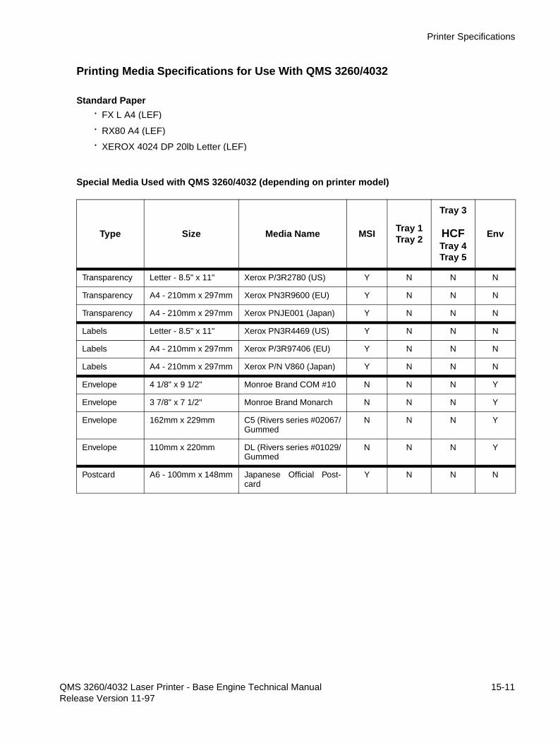
QMRe
Printer Specifications
Printing Media Specifications for Use With QMS 3260/4032
Standard Paper
· FX L A4 (LEF)
· RX80 A4 (LEF)
· XEROX 4024 DP 20lb Letter (LEF)
Special Media Used with QMS 3260/4032 (depending on printer model)
Type Size Media Name MSITray 1 Tray 2
Tray 3
HCFTray 4Tray 5
Env
Transparency Letter - 8.5" x 11" Xerox P/3R2780 (US) Y N N N
Transparency A4 - 210mm x 297mm Xerox PN3R9600 (EU) Y N N N
Transparency A4 - 210mm x 297mm Xerox PNJE001 (Japan) Y N N N
Labels Letter - 8.5" x 11" Xerox PN3R4469 (US) Y N N N
Labels A4 - 210mm x 297mm Xerox P/3R97406 (EU) Y N N N
Labels A4 - 210mm x 297mm Xerox P/N V860 (Japan) Y N N N
Envelope 4 1/8" x 9 1/2" Monroe Brand COM #10 N N N Y
Envelope 3 7/8" x 7 1/2" Monroe Brand Monarch N N N Y
Envelope 162mm x 229mm C5 (Rivers series #02067/Gummed
N N N Y
Envelope 110mm x 220mm DL (Rivers series #01029/Gummed
N N N Y
Postcard A6 - 100mm x 148mm Japanese Official Post-card
Y N N N
S 3260/4032 Laser Printer - Base Engine Technical Manual 15-11lease Version 11-97

15
Printer Specifications
Recommended Paper for Feed from QMS 3260/4032 Universal Trays
Weight Product Name
A3 Ledger B4 Legal 14"
Legal 13"
A4 Letter Exec-utive
B5 A5 Half Let-ter
20lb Xerox4024
Y Y Y LEF for
HCF
28lb Xerox4024
LEF for
HCF
20lb Nekosa LEF for
HCF
24lb Nekosa Y Y Y LEF for
HCF
LEF for
HCF
20lb Xerox MSI 3R2072
80gsm RX80(Black)
3R90120
3R90061
LEF for HCF
3R90008
MSI 3R9000
0
90gsm RX90 3R90614
LEF for HCF
3R90614
64gsm FX L stan-dard
Y MSI LEF for HCF
LEF for HCF
-12 QMS 3260/4032 Laser Printer - Base Engine Technical ManualRelease Version 11-97

QMRe
Printer Specifications
Image Reproduction and Registration SpecificationsEnvironmental conditions during the test:1 ~ 500 imp @ 18 ~ 27°C / 20 ~ 65% RH
501 ~ 10,000 imp @ 10 ~ 32°C / 15 ~ 85% RH
Measurement Measurement Accuracy Measurement conditions
Lead Edge Registration SIMPLEX: ±1.5mm
DUPLEX: ±1.9mm
MSI: ±2.1mm
--
Side Edge Registration SIMPLEX: ±2.0mm
DUPLEX: ±2.4mm
MSI: ±2.9mm
--
Skew SIMPLEX: ±1.54mm
DUPLEX: ±2.0mm
MSI: ±1.5mm
Viewed at a distance of 200mm
Perpendicularity SIMPLEX: ±1.7mm
DUPLEX: ±2.2mm
MSI: ±2.1mm
Viewed at a distance of 390mm
Parallelism SIMPLEX: ±2.0mm
DUPLEX: ±2.0mm
MSI: ±2.0mm
L=390mm
Vertical Magnification SIMPLEX:100 ±0.8%
DUPLEX: 100 ±0.8%
MSI:100 ±0.8%
Viewed at a distance of 220mm
Horizontal Magnification SIMPLEX:100 ±0.8%
DUPLEX: 100 ±0.8%
MSI:100 ±0.8%
View at a distance of 190mm
Vertical Linearity SIMPLEX: ±0.4mm
DUPLEX: ±0.4mm
MSI: ±0.4mm
For 390mm straight line
Horizontal Linearity SIMPLEX: ±0.4mm
DUPLEX: ±0.4mm
MSI: ±0.4mm
For 200mm straight line
Diagonal Linearity SIMPLEX: ±0.4mm
DUPLEX: ±0.4mm
MSI: ±0.4mm
For 200mm straight line
S 3260/4032 Laser Printer - Base Engine Technical Manual 15-13lease Version 11-97

15
Printer Specifications
Life Expectancy of Key Components
Printer OptionsThere are numerous customer installed options available for the QMS 3260/4032 printer. For detailed tech-nical and service information on an option, refer to the individual service manual for that option.
Component Replace at...
Fuser Unit 300,000 prints (B5)
Bias Transfer Roll 300,000 prints (B5)
Feed Rolls (3) 300,000 prints (B5)
Option Description
HCF Unit Tray 3 (500 sheets), Tray 4 (1,000 sheets), Tray 5 (1,000 sheets)
Envelope Feeder 100 envelopes
Face Up Tray Feeds 200 sheets face up
Mailbox Sorts 100 sheets into designated bins
HCS Unit Stacks, staples, and offsets
Duplex Module Allows printer to do duplex printing
Toner Sensor Factory installed option . Senses the toner level in the EP Cartridge.
Full Stack Sensor Factory installed option. Senses when the output tray is full.
Low Paper Sensor Factory installed option. Senses the paper level in a feed tray.
-14 QMS 3260/4032 Laser Printer - Base Engine Technical ManualRelease Version 11-97
QMRe
Glossary of Terms, Acronyms, and Abbreviations
Section 16 - Glossary of Terms, Acronyms, and Abbreviations
A-AC Alternating Current
Actuated A device that is switched on
Actuator Mechanical device used to toggle a switch or sensor
Aux Auxiliary
B-BCR Bias Charge Roll
BTR Bias Transfer Roll
C-°C Degrees Celsius
CCW Counterclockwise
Charge The negative voltage that the High Voltage Power Supply applies to the sur-face of the drum
Continuity A resistance reading of approximately 0 ohms
Controller PWB The electrical interface between the printer MCU and the host computer
CR Signal name for the Charge voltage
CRU Customer Replaceable Unit, such as the EP Cartridge
CW Clockwise
D-DC Direct Current
DB Signal name for the Developer Bias voltage
Deactuated A device that is switch off
Develop The process when toner adheres to the latent image on the drum
Developed image The visible image on the drum after going through the development stage
Diagnostic Mode The mode of operation that lets you check various components, such as sen-sors, solenoids, and motors
DPI Dots Per Inch
S 3260/4032 Laser Printer - Base Engine Technical Manual 16-1lease Version 11-97

16
Glossary of Terms, Acronyms, and Abbreviations
Drum The Xerographic photoreceptor
DTS Signal name for the Detack Saw voltage
DUP Duplex
Duplex Printing on both sides of a single sheet of paper
E-Earth Electrical ground
Earth Plate Electrical ground plate or ground strap
EP Cartridge Electro-Photography Cartridge; sometimes referred to as the Print Cartridge or as the CRU
Error Code A unique set of letters and numbers that the printer displays to indicate that a problem exists in a specific area of the printer
ESS Electronic Subsystem; synonym for the Controller PWB
Exposure The action of the laser beam striking and discharging select areas of the elec-trically charged surface of the drum
F-°F Degrees Fahrenheit
Face Down Tray Standard output tray for the printer. Delivers paper face down.
Face Up Tray Optional output tray for the printer. Delivers paper face up.
Factory default An adjustment value that is set at the time of equipment manufacture
FG Frame Ground
Finisher Synonym for the High Capacity Stacker
FIP Fault Isolation Procedure. Step by step procedures that you use to trouble-shoot printer problems
Fuser The printer subsystem that uses heat and pressure to permanently adhere, or fuse, a transferred toner image to a sheet of paper
G-Ground Electrical ground
-2 QMS 3260/4032 Laser Printer - Base Engine Technical Manual Release Version 11-97

QMRe
Glossary of Terms, Acronyms, and Abbreviations
H-Harness A bundle of wires that form a single unit and are generally terminated with
connectors at both ends
HCF High Capacity Feeder
HCS High Capacity Stacker. See Finisher.
High (signal) A signal voltage that is equal to or almost equal to the base voltage; such as +5VDC or +24VDC. (see Low)
H/R Heat Rod. A component of the Fuser Assembly
HS High Speed
HVPS High Voltage Power Supply
I-Input test Diagnostic test used to test switches and sensors
Image density The relative darkness of the toner image on a sheet of paper
Image development Toner turning the latent image into a visible image. (see Develop)Image fusing Using heat and pressure to permanently adhere the toner image to a sheet of
paper
Image transfer Moving the developed image from the surface of the drum to the surface of a sheet of paper
Interlock Interlock Switch. Used as a safety measure to remove voltage from circuits whenever the printer covers are open
IOT Image Output Terminal. Acronym that is sometimes used in schematic dia-grams to describe print engine
J-J Jack. A female electrical connector
L-Laser Diode Generates the laser beam that is used in the ROS
L Left
Latent image The invisible, electrical image remaining on the surface of the drum after exposure
L/H Left hand
Laser Refers to the Laser Diode or to the laser beam
S 3260/4032 Laser Printer - Base Engine Technical Manual 16-3lease Version 11-97
16
Glossary of Terms, Acronyms, and Abbreviations
Laser beam path The path the laser beam takes, through lenses and mirrors, from the Laser Diode to the surface of the drum
LCD Liquid Crystal Diode
LD Laser Diode. (see Laser Diode)
LED Light Emitting Diode
Low (signal) A signal voltage that is significantly lower than the base voltage (see High)
LVPS Low Voltage Power Supply
LS Low Speed
M-MCU Machine Control Unit. The PWB that controls the operation of the IOT
MBF Multi Bypass Feeder
MBX Mailbox
MID Middle
MOT Motor
MSI Multi Sheet Inserter (same as MBF)
N-NC No Connection
NVRAM Non-Volatile Random Access Memory
O-Output test Diagnostic tests used to switch on motors, solenoids, and the HVPS
P-Paper jam A sheet of paper stops at a point along the paper path
Paper path The path a sheet of paper takes from the paper feeder to the output tray
P/H Paper Handling
PL Parts List
PLL Phase Locked Loop
-4 QMS 3260/4032 Laser Printer - Base Engine Technical Manual Release Version 11-97

QMRe
Glossary of Terms, Acronyms, and Abbreviations
P Plug. A male electrical connector
P/J Plug and Jack. Electrical connectors as a unit
PPM Pages Per Minute or Prints Per Minute
Pre-Regi Pre-Registration
Print surface The side of a sheet of paper that receives the printed image
Primary FIP The first level of troubleshooting. Primary FIPS ask you to make component checks, replace parts, or proceed to a specific Secondary FIP
PS Power Supply
PWB Printed Wiring Board. Synonym for PCB (Printed Circuit Board)
R-Reg, or Regi Registration
R Right
R/H Right Hand
ROS Raster Output Scanner
RRP Removal and Replacement Procedure. Step by step instructions on how to remove and replace select printer parts
RTN Return
S-Secondary FIP The second level of troubleshooting. Secondary FIPS direct you to make
component checks and to replace parts
Sensor A device used to monitor a function or operation, such as paper travel along the paper path
SG Signal Ground
Signal name A name given to a wire indicating the purpose of the wire and/or the voltage carried by that wire
Simplex Generally means printing on one side of a single sheet of paper. (see Duplex)
SNR Sensor
SOL Solenoid
SOS Start Of Scan
S 3260/4032 Laser Printer - Base Engine Technical Manual 16-5lease Version 11-97

16
Glossary of Terms, Acronyms, and Abbreviations
STA Status
STS Soft Touch Sensor
SW Switch
T-Temp Temperature
Test Print Mode The mode of operation that lets you generate a test pattern
Test Pattern A grid that is generated by the MCU
Toggle To switch between two states, such as on and off or up and down
Toner The dry ink that is used to create the visible image. Toner is stored in the EP Cartridge
TR Signal name for Transfer current
Transfer Moving the toner image from the surface of the drum to the surface of a sheet of paper
TTL Transistor Transistor Logic
V-V Volts
VAC Volts Alternating Current
VDC Volts Direct Current
W-Warm-up The time it takes the printer to go from main power ON to Ready to Print
Wire Harness A bundle of wires that form a single unit and are generally terminated with connectors at both ends.
-6 QMS 3260/4032 Laser Printer - Base Engine Technical Manual Release Version 11-97