section 11 standards overviewftp.feq.ufu.br/luis_claudio/segurança/safety/double... ·...
TRANSCRIPT
1.8P1: xxx
31 August 1999 21:52 chap11.tex CHAP-11.SGM MH009v3(1999/07/12)
SECTION 11STANDARDS OVERVIEW∗
Terry BlevinsFisher-Rosemount Systems, Inc. Austin, Texas (Fieldbus)
Thomas G. Fisher, P. E.Lubrizol Corporation, Wickliffe, Ohio (Batch Control)
Paul Gruhn, P. E.Moore Products, Houston, Texas (Safety Instrumented[Interlock] Systems)
SAFETY INSTRUMENTED (INTERLOCK) SYSTEMS 11.3
INTRODUCTION 11.3
What People Really Want 11.3What the Standards Actually Are 11.3
DESIGN LIFE CYCLE 11.3
Conceptual Process Design 11.4Hazard Analysis and Risk Assessment 11.4Application of Non-SIS Layers 11.5Is an SIS Required? 11.5Define THE Target Safety Integrity Level 11.5Develop Safety Requirements Specification 11.5Conceptual SIS Design 11.6Detailed SIS Design 11.6Installation and Commissioning 11.7Operations and Maintenance 11.7Modifications 11.7Decommissioning 11.7
MULTIPLE INDEPENDENT SAFETY LAYERS 11.7
Process Plant Design 11.7Process Control System 11.8Alarms and Operators 11.8Shutdown/Interlock Systems 11.9Fire and Gas Systems 11.9Containment Systems 11.9Evacuation Procedures 11.9
SYSTEM TECHNOLOGIES 11.9
Logic Systems 11.9Field Devices 11.10Sensors 11.10Final Elements 11.11
SYSTEM ANALYSIS 11.11
Notes for Table 1 11.12
KEY POINTS 11.13
* Persons who authored complete articles or subsections of articles, or who otherwise cooperated in an outstanding mannerin furnishing information and helpful counsel to the editorial staff.
11.1
1.8P1: xxx
31 August 1999 21:52 chap11.tex CHAP-11.SGM MH009v3(1999/07/12)
11.2 PROCESS/INDUSTRIAL INSTRUMENTS AND CONTROLS HANDBOOK
RULES OF THUMB 11.13
REFERENCES 11.13
AN OVERVIEW OF THE ISA/IEC FIELDBUS 11.14
INTRODUCTION 11.14
PHYSICAL INSTALLATION OF A FIELDBUS SYSTEM 11.15
UTILIZING FIELDBUS DEVICES TO MEET
APPLICATION REQUIREMENTS 11.21
DIAGNOSTIC SUPPORT OF FOUNDATION FIELDBUS DEVICES 11.23
CONTROL SYSTEM IMPACT 11.27
EXAMPLE INSTALLATIONS: COMMERCIAL
FIELDBUS INSTALLATIONS 11.29
ESTIMATING SAVINGS FROM USING FIELDBUS TECHNOLOGY 11.30
Reduction of Terminations and Home Run Wiring 11.31Reduction in the Number of I/O Cards 11.32Reduction in Instrument Room Space 11.33
SUMMARY 11.33
Best Practices in Applying Fieldbus 11.34
REFERENCES 11.35
BATCH CONTROL: APPLYING THE S88.01 STANDARD 11.35
INTRODUCTION 11.35
DEFINITIONS 11.36
RECIPES 11.37
Recipe Types 11.37Recipe Information Categories 11.38
EQUIPMENT ENTITIES 11.40
Equipment Control 11.40Physical Model 11.40Partitioning Equipment Entities 11.42Procedural Control Model/Physical Model/Process Model
Relationship 11.43
RECIPE PROCEDURE/EQUIPMENT CONTROL SEPARATION 11.44
Control Recipe Procedure/Equipment Control Linking 11.46Control Recipe/Equipment Procedural Elements 11.47
PROCESS AND CONTROL ENGINEERING 11.47
CONTROL SYSTEM FUNCTIONAL SPECIFICATIONS 11.49
What Is Needed to Define Batch Control 11.49Equipment Entity Details 11.51
SUMMARY 11.56
Key Points 11.57Rules of Thumb [6] 11.58
REFERENCES 11.58
1.8P1: xxx
31 August 1999 21:52 chap11.tex CHAP-11.SGM MH009v3(1999/07/12)
STANDARDS OVERVIEW 11.3
SAFETY INSTRUMENTED(INTERLOCK) SYSTEMS
by Paul Gruhn∗
INTRODUCTION
This article provides an overview of the ISA Standard on Safety Systems (S84), with an emphasis onthe layers of protection and the estimates of the availability of different types of instrumentation andcontrols. The definition of a safety instrumented system is a system designed to respond to conditionsof a plant, which may be hazardous in themselves, or if no action were taken could eventually give riseto a hazard. It must generate the correct outputs to prevent the hazard or mitigate the consequences.
The ISA (International Society for Measurement and Control) S84 and IEC (International Elec-trotechnical Commission) 61508/61511 standards, along with the AIChE CCPS (American Instituteof Chemical Engineers, Center for Chemical Process Safety) Guidelines on safety instrumented (in-terlock) systems, as well as process safety management legislation [1]–[4] are performance oriented,not prescriptive. They do not tell people what technology logic system to use (relay, solid state, orsoftware based), what logic and field device configuration to use (single, dual, or triplicated), or howoften to test a system (monthly, quarterly, or yearly). They merely list the performance requirementsfor the overall system. In other words, the greater the level of risk of the process, the greater theperformance needed of the safety instrumented system.
What People Really Want
However, what most people really want is a simple “cookbook” of preplanned solutions. For example,for a refinery, turn to page 35 in standard ABC. There it shows dual sensor, dual logic, simplexvalves, yearly test interval, and so on. For an offshore platform, turn to page 63. There it shows. . . .Unfortunately, at this point in time, industry standards are not written this way. The standards donot give clear, simple, precise answers. They do not mandate technology, level or redundancy, or testintervals.
What the Standards Actually Are
There is a fundamental change in the way industry standards are being written. Standards are movingaway from prescriptive standards and toward more performance-oriented requirements. After all, it’srelatively easy to be prescriptive about something we have a great deal of experience with (e.g.,boilers). The same cannot be said of relatively new and unproven processes. This means each plantwill have to decide for itself just what is safe, and each plant will have to decide on how it willdetermine and document that its systems are, in fact, safe. Unfortunately, these are difficult decisionsthat few want to make, and fewer still want to put in writing.
DESIGN LIFE CYCLE
Designing a single component may be viewed as a relatively simple matter, one that a single personcan handle. Designing any large system, whether it’s a car, a computer, an airplane, or a safetyinstrumented system, however, is typically beyond the ability of any single individual. Large systems
* P.E., Moore Products, Houston, Texas.
1.8P1: xxx
31 August 1999 21:52 chap11.tex CHAP-11.SGM MH009v3(1999/07/12)
11.4 PROCESS/INDUSTRIAL INSTRUMENTS AND CONTROLS HANDBOOK
No
Yes
Perform DetailESD Design
Develop SafetyReq
,s
Establish Operations &Maintenance Procedures
Pre-start, Operation,Maintenance & Testing
Maintenance & Testing
Modify
SISDecommissioning
ConceptualProcess Design
Conceptual SISDesign
Perform Hazard & Risk Assessment
Apply non SIS layers
Define target SIL
SIS Installation &Commissioning
Modify orDecommission
SISRequired
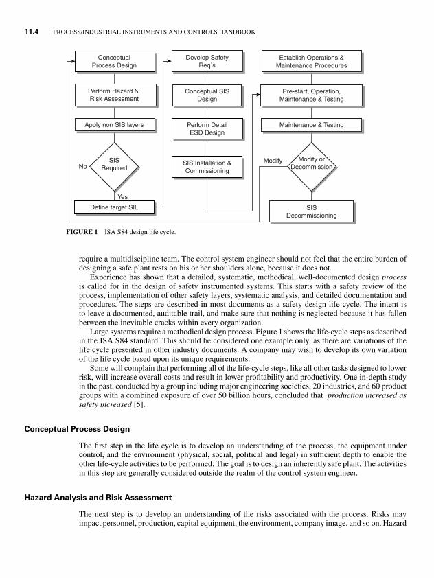
FIGURE 1 ISA S84 design life cycle.
require a multidiscipline team. The control system engineer should not feel that the entire burden ofdesigning a safe plant rests on his or her shoulders alone, because it does not.
Experience has shown that a detailed, systematic, methodical, well-documented design processis called for in the design of safety instrumented systems. This starts with a safety review of theprocess, implementation of other safety layers, systematic analysis, and detailed documentation andprocedures. The steps are described in most documents as a safety design life cycle. The intent isto leave a documented, auditable trail, and make sure that nothing is neglected because it has fallenbetween the inevitable cracks within every organization.
Large systems require a methodical design process. Figure 1 shows the life-cycle steps as describedin the ISA S84 standard. This should be considered one example only, as there are variations of thelife cycle presented in other industry documents. A company may wish to develop its own variationof the life cycle based upon its unique requirements.
Some will complain that performing all of the life-cycle steps, like all other tasks designed to lowerrisk, will increase overall costs and result in lower profitability and productivity. One in-depth studyin the past, conducted by a group including major engineering societies, 20 industries, and 60 productgroups with a combined exposure of over 50 billion hours, concluded that production increased assafety increased [5].
Conceptual Process Design
The first step in the life cycle is to develop an understanding of the process, the equipment undercontrol, and the environment (physical, social, political and legal) in sufficient depth to enable theother life-cycle activities to be performed. The goal is to design an inherently safe plant. The activitiesin this step are generally considered outside the realm of the control system engineer.
Hazard Analysis and Risk Assessment
The next step is to develop an understanding of the risks associated with the process. Risks mayimpact personnel, production, capital equipment, the environment, company image, and so on. Hazard
1.8P1: xxx
31 August 1999 21:52 chap11.tex CHAP-11.SGM MH009v3(1999/07/12)
STANDARDS OVERVIEW 11.5
analysis consists of identifying the hazards. There are numerous techniques one can use (HAZOP, WhatIf, Fault Tree, Checklist, etc.) and numerous texts describing each method [6]–[8]. Risk assessmentconsists of classifying the risk of the hazards that have been identified in the hazard analysis. Riskis a function of the frequency or probability of an event, and the severity or consequences of theevent. Risk assessment can be either qualitative or quantitative. Qualitative assessments subjectivelyrank the risks from low to high; quantitative assessments, as the name obviously implies, attempt toassign numerical factors to the risk, such as death or accident rates. This is not intended to be thesole responsibility of the control system engineer. There are obviously a number of other disciplinesrequired in order to perform these assessments.
Application of Non-SIS Layers
The goal of process plant design is have a plant that is inherently safe, or one where residual riskscan be controlled by the application of noninstrumented safety layers. KISS (keep it simple, stupid)should be an overriding theme.
Is an SIS Required?
If the risks can be controlled to an acceptable level without the application of an instrumented system,then the design process stops (as far as a safety instrumented system is concerned). If the risks cannotbe controlled to an acceptable level by the application of noninstrumented layers, then an instrumentedsystem will be required.
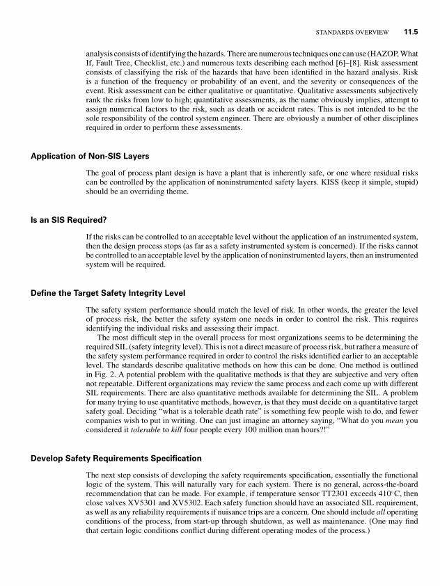
Define the Target Safety Integrity Level
The safety system performance should match the level of risk. In other words, the greater the levelof process risk, the better the safety system one needs in order to control the risk. This requiresidentifying the individual risks and assessing their impact.
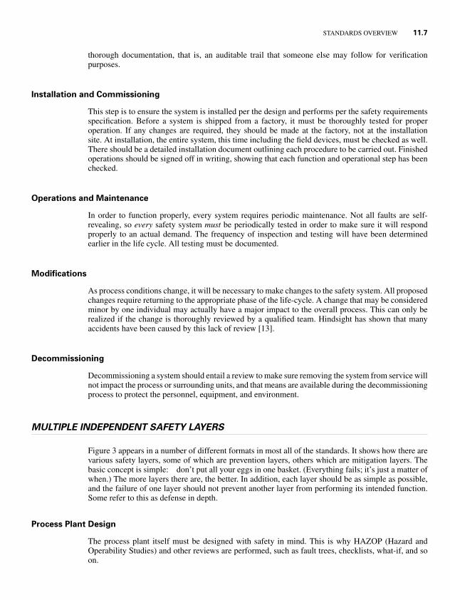
The most difficult step in the overall process for most organizations seems to be determining therequired SIL (safety integrity level). This is not a direct measure of process risk, but rather a measure ofthe safety system performance required in order to control the risks identified earlier to an acceptablelevel. The standards describe qualitative methods on how this can be done. One method is outlinedin Fig. 2. A potential problem with the qualitative methods is that they are subjective and very oftennot repeatable. Different organizations may review the same process and each come up with differentSIL requirements. There are also quantitative methods available for determining the SIL. A problemfor many trying to use quantitative methods, however, is that they must decide on a quantitative targetsafety goal. Deciding “what is a tolerable death rate” is something few people wish to do, and fewercompanies wish to put in writing. One can just imagine an attorney saying, “What do you mean youconsidered it tolerable to kill four people every 100 million man hours?!”
Develop Safety Requirements Specification
The next step consists of developing the safety requirements specification, essentially the functionallogic of the system. This will naturally vary for each system. There is no general, across-the-boardrecommendation that can be made. For example, if temperature sensor TT2301 exceeds 410◦C, thenclose valves XV5301 and XV5302. Each safety function should have an associated SIL requirement,as well as any reliability requirements if nuisance trips are a concern. One should include all operatingconditions of the process, from start-up through shutdown, as well as maintenance. (One may findthat certain logic conditions conflict during different operating modes of the process.)

1.8P1: xxx
31 August 1999 21:52 chap11.tex CHAP-11.SGM MH009v3(1999/07/12)
11.6 PROCESS/INDUSTRIAL INSTRUMENTS AND CONTROLS HANDBOOK
X1
X2
X3
X4
X5
X6
Pa
Pb
Pa
Pb
Pa
Pb
Pa
Pb
Fb
Fa
Fb
Fa
FbFa
Cd
Cc
Cb
Ca
W3
a
1
2
3
4
b
W2
−
a
1
2
3
4
W1
−
−
a
1
2
3
Consequence
C Minor InjuryCb Serious Injury, Single DeathCc Several DeathsCd Many Deaths
Frequency & Exposure
Fa Rare to FrequentFb Frequent to Continuous
Possibility of Avoidance
Pa Sometimes PossiblePb Almost Impossible
Probability of Occurrence
W1 Very SlightW2 SlightW3 Relatively High
a = No special safety requirementsb = Single SIS not sufficient Safety Integrity
FIGURE 2 One qualitative method of determining the required SIL.
The system will be programmed and tested according to the logic determined during this step. Ifan error is made here, it will carry through for the rest of the design. It won’t matter how redundant orhow often the system is manually tested—it will not work properly when required. These are referredto as systematic, or functional, failures. Using diverse redundant systems, programmed by differentpeople using different languages and tested by an independent team, will not help in this situation,because the functional logic they all based their work on could be in error.
Conceptual SIS Design
One doesn’t pick a certain size jet engine for an aircraft based on intuition. One doesn’t size a milliondollar compressor by gut feel. One doesn’t determine the size of pilings required for a bridge by trailand error (at least not any more).
The purpose of this step is to develop an initial design in order to see if it meets the safety require-ments and SIL performance requirements. Initially one needs to select a technology, configuration(architecture), test interval, and so on. This pertains to the field devices as well as the logic box.Factors to consider are overall size, budget, complexity, speed of response, communication require-ments, interface requirements, method of implementing bypasses, testing, and so on. One can thenperform a relatively simple quantitative analysis to see if the proposed system meets the performancerequirements [9]–[12], or make a qualitative judgment based on prior experience (although this isobviously harder to substantiate). The intent is to evaluate the system before one specifies the solution.Just as it is better to perform a HAZOP before you build the plant (it’s hard to change the design onceit’s already been built), it is better to analyze the proposed safety system before you specify it, or elsehow will you know if it meets the performance goal?
Detailed SIS Design
The purpose of this step is to finalize and document the design. Once a design has been chosen, thesystem must be engineered and built following strict and conservative procedures. This is the onlyrealistic method of preventing design and implementation errors that we know of. The process requires
1.8P1: xxx
31 August 1999 21:52 chap11.tex CHAP-11.SGM MH009v3(1999/07/12)
STANDARDS OVERVIEW 11.7
thorough documentation, that is, an auditable trail that someone else may follow for verificationpurposes.
Installation and Commissioning
This step is to ensure the system is installed per the design and performs per the safety requirementsspecification. Before a system is shipped from a factory, it must be thoroughly tested for properoperation. If any changes are required, they should be made at the factory, not at the installationsite. At installation, the entire system, this time including the field devices, must be checked as well.There should be a detailed installation document outlining each procedure to be carried out. Finishedoperations should be signed off in writing, showing that each function and operational step has beenchecked.
Operations and Maintenance
In order to function properly, every system requires periodic maintenance. Not all faults are self-revealing, so every safety system must be periodically tested in order to make sure it will respondproperly to an actual demand. The frequency of inspection and testing will have been determinedearlier in the life cycle. All testing must be documented.
Modifications
As process conditions change, it will be necessary to make changes to the safety system. All proposedchanges require returning to the appropriate phase of the life-cycle. A change that may be consideredminor by one individual may actually have a major impact to the overall process. This can only berealized if the change is thoroughly reviewed by a qualified team. Hindsight has shown that manyaccidents have been caused by this lack of review [13].
Decommissioning
Decommissioning a system should entail a review to make sure removing the system from service willnot impact the process or surrounding units, and that means are available during the decommissioningprocess to protect the personnel, equipment, and environment.
MULTIPLE INDEPENDENT SAFETY LAYERS
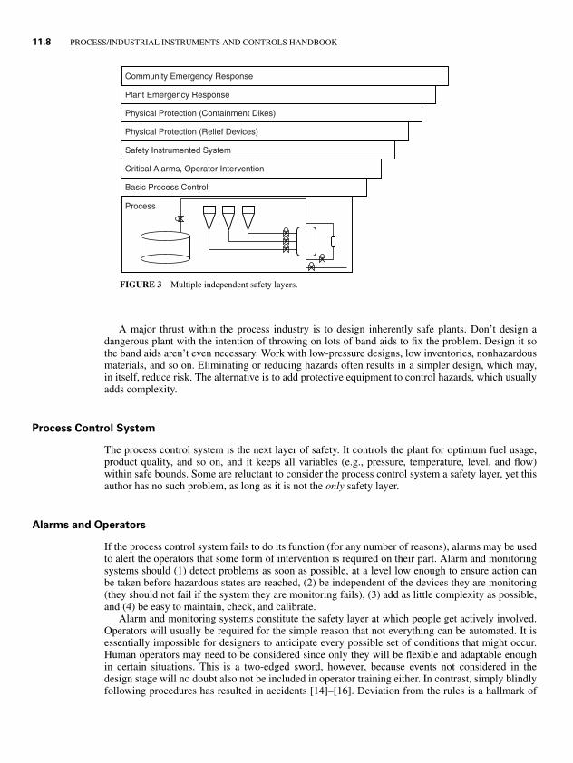
Figure 3 appears in a number of different formats in most all of the standards. It shows how there arevarious safety layers, some of which are prevention layers, others which are mitigation layers. Thebasic concept is simple: don’t put all your eggs in one basket. (Everything fails; it’s just a matter ofwhen.) The more layers there are, the better. In addition, each layer should be as simple as possible,and the failure of one layer should not prevent another layer from performing its intended function.Some refer to this as defense in depth.
Process Plant Design
The process plant itself must be designed with safety in mind. This is why HAZOP (Hazard andOperability Studies) and other reviews are performed, such as fault trees, checklists, what-if, and soon.
1.8P1: xxx
31 August 1999 21:52 chap11.tex CHAP-11.SGM MH009v3(1999/07/12)
11.8 PROCESS/INDUSTRIAL INSTRUMENTS AND CONTROLS HANDBOOK
Community Emergency Response
Plant Emergency Response
Physical Protection (Containment Dikes)
Physical Protection (Relief Devices)
Safety Instrumented System
Critical Alarms, Operator Intervention
Basic Process Control
Process
FIGURE 3 Multiple independent safety layers.
A major thrust within the process industry is to design inherently safe plants. Don’t design adangerous plant with the intention of throwing on lots of band aids to fix the problem. Design it sothe band aids aren’t even necessary. Work with low-pressure designs, low inventories, nonhazardousmaterials, and so on. Eliminating or reducing hazards often results in a simpler design, which may,in itself, reduce risk. The alternative is to add protective equipment to control hazards, which usuallyadds complexity.
Process Control System
The process control system is the next layer of safety. It controls the plant for optimum fuel usage,product quality, and so on, and it keeps all variables (e.g., pressure, temperature, level, and flow)within safe bounds. Some are reluctant to consider the process control system a safety layer, yet thisauthor has no such problem, as long as it is not the only safety layer.
Alarms and Operators
If the process control system fails to do its function (for any number of reasons), alarms may be usedto alert the operators that some form of intervention is required on their part. Alarm and monitoringsystems should (1) detect problems as soon as possible, at a level low enough to ensure action canbe taken before hazardous states are reached, (2) be independent of the devices they are monitoring(they should not fail if the system they are monitoring fails), (3) add as little complexity as possible,and (4) be easy to maintain, check, and calibrate.
Alarm and monitoring systems constitute the safety layer at which people get actively involved.Operators will usually be required for the simple reason that not everything can be automated. It isessentially impossible for designers to anticipate every possible set of conditions that might occur.Human operators may need to be considered since only they will be flexible and adaptable enoughin certain situations. This is a two-edged sword, however, because events not considered in thedesign stage will no doubt also not be included in operator training either. In contrast, simply blindlyfollowing procedures has resulted in accidents [14]–[16]. Deviation from the rules is a hallmark of
1.8P1: xxx
31 August 1999 21:52 chap11.tex CHAP-11.SGM MH009v3(1999/07/12)
STANDARDS OVERVIEW 11.9
experienced people, but it is bound to lead to occasional human error and related blame after thefact.
Shutdown/Interlock Systems
If the control system and the operators fail to act, automatic shutdown systems take control. Thesesystems are usually completely separate, with their own final elements. These systems require ahigher degree of security to prevent inadvertent changes and tampering, and a greater level of faultdiagnostics. The focus of this chapter is on these systems.
Fire and Gas Systems
If the shutdown system fails and an accident ensues, fire and gas systems may be used to mitigate orlessen the consequences of the event. In the U.S., these are traditionally alarm-only systems—theydo not take any automatic control actions. Typically, the fire crews must go out and manually put outthe fire. Outside the U.S., these systems frequently take some form of control actions, or they may beintegrated with the shutdown system.
Containment Systems
If an atmospheric storage tank were to burst, dikes could be available to contain the release. In nuclearpower plants, reactor are usually housed in containment buildings to prevent accidental releases. (TheSoviet reactor at Chernobyl did not have a containment building, whereas the U.S. reactor at ThreeMile Island did.)
Evacuation Procedures
In the event of a catastrophic release, evacuation procedures are used to evacuate plant personnel fromthe area, and if necessary, even the outside community. While these are procedures only, and not aphysical system (apart from sirens), they may still be considered one of the overall safety layers.
SYSTEM TECHNOLOGIES
Logic Systems
There are a number of technologies available for use in shutdown systems—pneumatic, electrome-chanical relays, solid state, and PLCs (programmable logic controllers). There is no one overall bestsystem; each has advantages and disadvantages. The decision of which system may be best suitedfor an application will depend upon many factors, such as budget, size, level of risk, flexibility,maintenance, interface and communication requirements, security, and so on.
Pneumatic systems are most suitable for small applications in which there are concern over sim-plicity, intrinsic safety, and lack of available electrical power.
Relay systems are fairly simple, are relatively inexpensive to purchase, are immune to most formsof EMI/RFI interference, and can be built for many different voltage ranges. They generally do notincorporate any form of interface or communications. Changes to logic require a manual change ofdocumentation. In general, relay systems are usually only used for relatively small applications.
Solid-state systems (hardwired systems that do not incorporate software) are also available. Sev-eral of these systems were built specifically for safety applications and include features for testing,

1.8P1: xxx
31 August 1999 21:52 chap11.tex CHAP-11.SGM MH009v3(1999/07/12)
11.10 PROCESS/INDUSTRIAL INSTRUMENTS AND CONTROLS HANDBOOK
bypasses, and communications. Logic changes still require a manual change of documentation. Thesesystems have fallen out of favor with many people because of their high cost, along with the acceptanceof software-based systems.
Software-based systems, generally industrial PLCs, offer software flexibility, self-documentation,communications, and higher level interfaces. Unfortunately, many general purpose systems were notdesigned specifically for safety and do not offer features required for more critical applications (such aseffective self-diagnostics). However, certain specialized dual and triplicated systems were developedfor more critical applications and have become firmly established in the process industry.
Field Devices
In the process industries more hardware faults occur in the peripheral equipment—that is, the mea-suring instruments/transmitters and the control valves—than in the logic system itself. The overallreliability of a computerized control system may therefore not be significantly different than a con-ventional hardwired electrical system [17].
Sensors
Sensors are used to measure process variables, such as temperature, pressure, flow, level, and so on.They may consist of simple pneumatic or electric switches, which change state when a setpoint isreached, or they may contain pneumatic or electric analog transmitters, which give a variable outputin relation to the strength or level of the process variable.
Sensors, like any other device, may fail in a number of different manners. They may cause nuisancetrips, that is, respond without any change of input signal. They may also fail to respond to an actualchange of input conditions. While these are the two failure modes of most concern for safety systems,there are additional failure modes as well, such as leaking, erratic output, and responding at an incorrectlevel.
Most shutdown systems are designed to be fail safe. This usually means that when power is lost,the safety system makes the process revert to a safe state, which usually means stopping production.(Nuisance trips should be avoided for safety reasons as well. Startup and shutdown modes of operationinvolve the highest levels of risk.) Thought must be given to how the sensors should respond in orderto be fail-safe. This usually means the sensor has normally closed and energized contacts, althoughthis is not always the case. Transmitters can usually be configured to fail upscale or downscale in theevent of a failure of the internal electronics. Thought should be given to the failure mode for each typeof transmitter. A recommendation that is overall, across the board, and the same for all applicationssimply cannot be made.
Some measurements may be inferred from other variables. For example, if a system is designedto shutdown as a result of high pressure, it may be helpful to monitor temperature (if, because of theprocess, an elevated temperature might also imply a high pressure). Special care should be taken whenoperating sensors at the low end of their ranges, because of the potential low-accuracy problems. Forexample, a sensor designed to operate at 1,000 psi may not be able to differentiate between 20 and25 psi.
Technologies. Discrete switches do not provide any form of diagnostic information. For example,if under normal circumstances a pressure sensor has a closed set of alarm contacts that are designedto open upon low pressure, and the contacts become stuck and cannot open as a result, the sensor hasno means to annunciate the failure. The only way to know whether devices such as these are workingis to test them.
Transmitters, in contrast, provide an analog signal in relation to the input variable, thus indicatingin a limited sense whether the device is functioning properly. Any information is better than none.However, if the transmitter output is never monitored by the operators, or if the logic system does not

1.8P1: xxx
31 August 1999 21:52 chap11.tex CHAP-11.SGM MH009v3(1999/07/12)
STANDARDS OVERVIEW 11.11
automatically check for “noise” or occasional drifting of the signal, then there really may be no moreusable information than a discrete switch. It would be like having a color printer, but only printingblack and white documents. The perceived benefit of having the color printer is illusory if one isusuable to take advantage of the desired feature.
Redundancy. If the failure of any one sensor is of concern (i.e., a nuisance trip or a fail-to-functionfailure), then redundant or multiple sensors may be used. Ideally, the possibility of two sensors failingat the same time should be very remote. Unfortunately, this does not account for common causefailures, which might impact multiple sensors at the same time. Common cause failures are usuallyassociated with external environmental factors such as heat, vibration, corrosion, and plugging. Ifmultiple sensors are to be used, they should be connected to the process using different taps, so as toavoid common cause plugging failures. Consideration may be given to using different sensors fromdifferent manufacturers, or having different maintenance personnel work on the sensors (so as to avoidthe possibility of a maintenance technician incorrectly calibrating all the sensors).
Final Elements
Final elements generally have the highest failure rates. They are mechanical devices and subject toharsh process conditions. Safety shutoff valves also suffer from the fact that they are usually openand not activated for long periods of time, except for testing. One of the most common failure modesis that the valve is stuck, or frozen in place.
Valves should be fail safe upon loss of power. This usually requires a spring. A pneumatic orhydraulic valve would require a volume bottle to be fail safe, but the “availability” of the bottles maybe too poor to rely on.
Solenoids. Solenoids are one of the most critical components of final elements. It is important touse a good industrial grade solenoid valve, especially for outdoor use. The valve must be able towithstand high temperatures, including the heat generated by the coil itself. In general, the reliabilityof solenoids is very low. One of the most common failures is burning out a coil, which causes a falsetrip. A dual coil would keep the solenoid energized if one coil were to burn out. Solenoids should betested frequently.
SYSTEM ANALYSIS
What is suitable for SIL 1, for SIL 2, and SIL 3? Things are not as intuitively obvious as they mayseem. Dual is not always better than simplex, and triple is not always better than dual. Which tech-nology to use, what level of redundancy, what manual test interval, and what about the field devices?
We do not design nuclear power plants or aircraft by gut feel or intuition. As engineers, we must relyon quantitative evaluations as the basis for our judgments. A quantitative analysis may be impreciseand imperfect, but it nevertheless is a valuable exercise for the following reasons:
1. It provides an early indication of a system’s potential to meet the design requirements.
2. It enables one to determine the weak link in the system (and fix it, if necessary).
In order to predict the performance of a system, one needs performance data of all the components. In-formation is available from user records, vendor records, military-style predictions, and commerciallyavailable databases in different industries.
When modeling the performance of a safety system, one needs to consider two failure modes.Safe failures result in nuisance trips and lost production. The preferred term for these failures is thenuisance trip rate (measured in years). Dangerous failures result in hidden failures in which the system
1.8P1: xxx
31 August 1999 21:52 chap11.tex CHAP-11.SGM MH009v3(1999/07/12)
11.12 PROCESS/INDUSTRIAL INSTRUMENTS AND CONTROLS HANDBOOK
will not respond when required. Common terms used to quantify performance in this mode are pfd(probability of failure on demand), RRF (Risk Reduction Factor), and SA (Safety Availability).
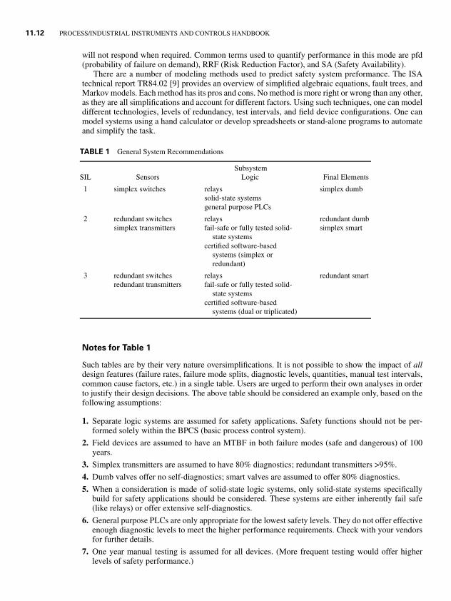
There are a number of modeling methods used to predict safety system preformance. The ISAtechnical report TR84.02 [9] provides an overview of simplified algebraic equations, fault trees, andMarkov models. Each method has its pros and cons. No method is more right or wrong than any other,as they are all simplifications and account for different factors. Using such techniques, one can modeldifferent technologies, levels of redundancy, test intervals, and field device configurations. One canmodel systems using a hand calculator or develop spreadsheets or stand-alone programs to automateand simplify the task.
TABLE 1 General System Recommendations
SubsystemSIL Sensors Logic Final Elements
1 simplex switches relays simplex dumbsolid-state systemsgeneral purpose PLCs
2 redundant switches relays redundant dumbsimplex transmitters fail-safe or fully tested solid- simplex smart
state systemscertified software-based
systems (simplex orredundant)
3 redundant switches relays redundant smartredundant transmitters fail-safe or fully tested solid-
state systemscertified software-based
systems (dual or triplicated)
Notes for Table 1
Such tables are by their very nature oversimplifications. It is not possible to show the impact of alldesign features (failure rates, failure mode splits, diagnostic levels, quantities, manual test intervals,common cause factors, etc.) in a single table. Users are urged to perform their own analyses in orderto justify their design decisions. The above table should be considered an example only, based on thefollowing assumptions:
1. Separate logic systems are assumed for safety applications. Safety functions should not be per-formed solely within the BPCS (basic process control system).
2. Field devices are assumed to have an MTBF in both failure modes (safe and dangerous) of 100years.
3. Simplex transmitters are assumed to have 80% diagnostics; redundant transmitters >95%.
4. Dumb valves offer no self-diagnostics; smart valves are assumed to offer 80% diagnostics.
5. When a consideration is made of solid-state logic systems, only solid-state systems specificallybuild for safety applications should be considered. These systems are either inherently fail safe(like relays) or offer extensive self-diagnostics.
6. General purpose PLCs are only appropriate for the lowest safety levels. They do not offer effectiveenough diagnostic levels to meet the higher performance requirements. Check with your vendorsfor further details.
7. One year manual testing is assumed for all devices. (More frequent testing would offer higherlevels of safety performance.)
1.8P1: xxx
31 August 1999 21:52 chap11.tex CHAP-11.SGM MH009v3(1999/07/12)
STANDARDS OVERVIEW 11.13
8. Redundant configurations are assumed to be either 1oo2 or 2oo3. 1oo2 configurations are safe, atthe expense of more nuisance trips. 2oo2 configurations are less safe than simplex and should onlybe used if it can be documented that they meet the overall safety requirements.
9. The above table does not categorize the nuisance trip performance of any of the systems.
KEY POINTS
� follow the steps defined in the safety design life cycle� if you can’t define it, you can’t control it� justify and document all of your decisions (i.e., leave an auditable trail)� the goal is to have an inherently safe process (i.e., one where you don’t even need an SIS)� don’t put all of your eggs in one basket (i.e., have multiple, independent safety layers)� the SIS should be fail safe and/or fault tolerant� analyze the problem before you specify the solution� all systems must be periodically tested� never leave points in bypass during normal operation (or be prepared to suffer the consequences)
RULES OF THUMB
� maximize diagnostics (This is the most critical factor in safety performance.)� any indication is better than none (e.g., transmitters have advantages over switches, systems should
provide indications even signals are in bypass, etc.)� minimize potential common cause problems� general purpose PLCs are not suitable for the higher safety integrity levels� when possible, use independently approved and/or certified components/systems (e.g., FM, TUV,
etc.)
REFERENCES
1. “Application of Safety Instrumented Systems for the Process Industries,” ANSI/ISA-S84.01-, 1996.
2. “Functional Safety—Safety Related Systems,” IEC Draft Standard 61508, 1997.
3. Guidelines for Safe Automation of Chemical Processes, AIChE, CCPS, 1993.
4. CFR Part 1910.119, Process Safety Management of Highly Hazardous Chemicals U.S. Federal Register,February 24, 1992.
5. Leveson, N. G.; Safeware—System Safety and Computers, Addison-Wesley, Reading, Mass., 1995.
6. Guidelines for Hazard Evaluation Procedures, AIChE CCPS, 1992.
7. Guidelines for Chemical Process Quantitative Risk Analysis, AIChE CCPS, 1989.
8. Taylor, J. R., Risk Analysis for Process Plants, Pipelines and Transport, E & FN Spon, an Imprint of Chapman& Hall, London, UK, 1994.
9. “Safety Instrumented System (SIS)—Safety Integrity Level (SIL) Evaluation Techniques,” ISA Draft Tec.Rep. dTR84.02, 1997.
10. Gruhn, P., “The Evaluation of Safety Instrumented Systems—Tools to Peer Past the Hype,” ISA transactionsVol. 35, pp. 25–32, 1996.
1.8P1: xxx
31 August 1999 21:52 chap11.tex CHAP-11.SGM MH009v3(1999/07/12)
11.14 PROCESS/INDUSTRIAL INSTRUMENTS AND CONTROLS HANDBOOK
11. Gruhn, P., “Safety Systems: Where is Your Weak Link?” InTech, December 1993.
12. Smith, D. J., Reliability, Maintainability and Risk, Butterworth Heinemann, Oxford, UK, 1993.
13. “Out of Control: Why Control Systems Go Wrong and How To Prevent Failure,” Health & Safety Executive(UK), 1995.
14. Kletz, T. A., What Went Wrong? Case Histories of Process Plant Disasters, Gulf Publishing, Houston, TX,1986.
15. Kletz, T. A., An Engineer’s View Of Human Error, The Institute of Chemical Engineers, Warwickshire,England, 1985.
16. Kletz, T. A., Lessons From Disaster—How Organizations Have No Memory and Accidents Recur, GulfPublishing, Houston, TX, 1993.
17. Lowe, X., Measurement and Control, Vol. 17; p. 317, 1984.
AN OVERVIEW OF THE ISA/IECFIELDBUS
by Terry Blevins∗
INTRODUCTION
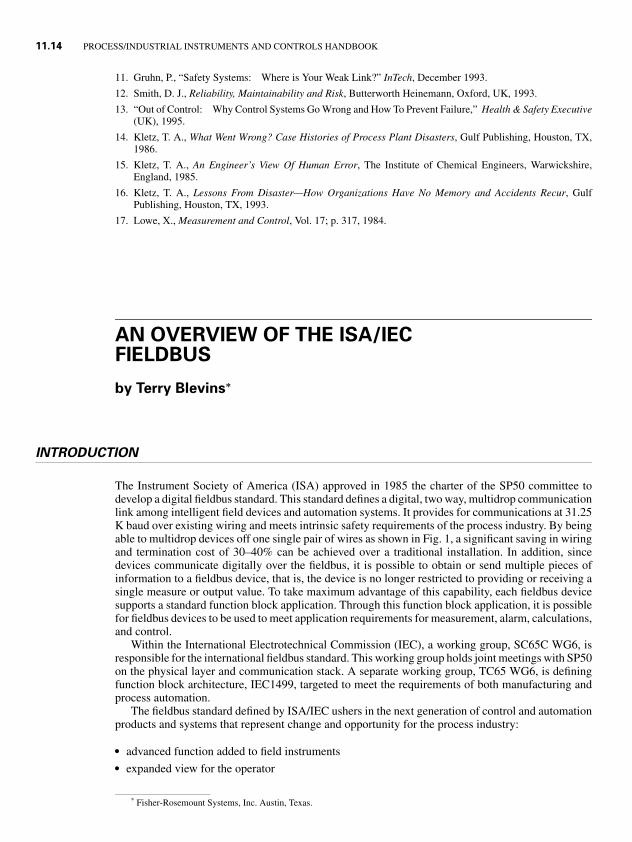
The Instrument Society of America (ISA) approved in 1985 the charter of the SP50 committee todevelop a digital fieldbus standard. This standard defines a digital, two way, multidrop communicationlink among intelligent field devices and automation systems. It provides for communications at 31.25K baud over existing wiring and meets intrinsic safety requirements of the process industry. By beingable to multidrop devices off one single pair of wires as shown in Fig. 1, a significant saving in wiringand termination cost of 30–40% can be achieved over a traditional installation. In addition, sincedevices communicate digitally over the fieldbus, it is possible to obtain or send multiple pieces ofinformation to a fieldbus device, that is, the device is no longer restricted to providing or receiving asingle measure or output value. To take maximum advantage of this capability, each fieldbus devicesupports a standard function block application. Through this function block application, it is possiblefor fieldbus devices to be used to meet application requirements for measurement, alarm, calculations,and control.
Within the International Electrotechnical Commission (IEC), a working group, SC65C WG6, isresponsible for the international fieldbus standard. This working group holds joint meetings with SP50on the physical layer and communication stack. A separate working group, TC65 WG6, is definingfunction block architecture, IEC1499, targeted to meet the requirements of both manufacturing andprocess automation.
The fieldbus standard defined by ISA/IEC ushers in the next generation of control and automationproducts and systems that represent change and opportunity for the process industry:
� advanced function added to field instruments� expanded view for the operator
* Fisher-Rosemount Systems, Inc. Austin, Texas.
1.8P1: xxx
31 August 1999 21:52 chap11.tex CHAP-11.SGM MH009v3(1999/07/12)
STANDARDS OVERVIEW 11.15
FIGURE 1 Fieldbus segment: multiple devices may be connected to a single fieldbus segment.
� reduced wiring and installation costs� reduced I/O equipment by one-half or more� provide increased information flow to enable automation of engineering, maintenance, and support
functions
The Fieldbus Foundation (FF) is an independent, nonprofit organization established to support com-mercialization of the ISA/IEC fieldbus standard. Foundation Fieldbus devices use the IEC physi-cal layer and communication stack. The Function Block Application Process defined by the Field-bus Foundation specification includes architectural concepts and terminology of IEC1499. Trainingschools are sponsored by the Foundation to support fieldbus device development. In addition, theFoundation has established test procedures, which are used to certify field devices as interoperable.
PHYSICAL INSTALLATION OF A FIELDBUS SYSTEM
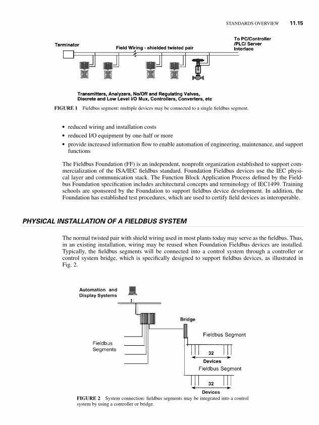
The normal twisted pair with shield wiring used in most plants today may serve as the fieldbus. Thus,in an existing installation, wiring may be reused when Foundation Fieldbus devices are installed.Typically, the fieldbus segments will be connected into a control system through a controller orcontrol system bridge, which is specifically designed to support fieldbus devices, as illustrated inFig. 2.
FIGURE 2 System connection: fieldbus segments may be integrated into a controlsystem by using a controller or bridge.
1.8P1: xxx
31 August 1999 21:52 chap11.tex CHAP-11.SGM MH009v3(1999/07/12)
11.16 PROCESS/INDUSTRIAL INSTRUMENTS AND CONTROLS HANDBOOK
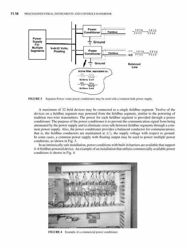
FIGURE 3 Segment Power: some power conditioners may be used with a common bulk power supply.
A maximum of 32 field devices may be connected to a single fieldbus segment. Twelve of thedevices on a fieldbus segment may powered from the fieldbus segment, similar to the powering oftradition two-wire transmitters. The power for each fieldbus segment is provided through a powerconditioner. The purpose of the power conditioner is to prevent the communication signal from beingattenuated by the power supply and to eliminate cross talk between fieldbus segments through a com-mon power supply. Also, the power conditioner provides a balanced conductor for communications;that is, the fieldbus conductors are maintained at ±1/2 the supply voltage with respect to ground.In some cases, a common power supply with floating output may be used to power multiple powerconditions, as shown in Fig. 3.
In an intrinsically safe installation, power conditions with built-in barriers are available that support4–6 fieldbus powered device. An example of an installation that utilizes commercially available powerconditions is shown in Fig. 4.
FIGURE 4 Example of a commercial power conditioner.
1.8P1: xxx
31 August 1999 21:52 chap11.tex CHAP-11.SGM MH009v3(1999/07/12)
STANDARDS OVERVIEW 11.17
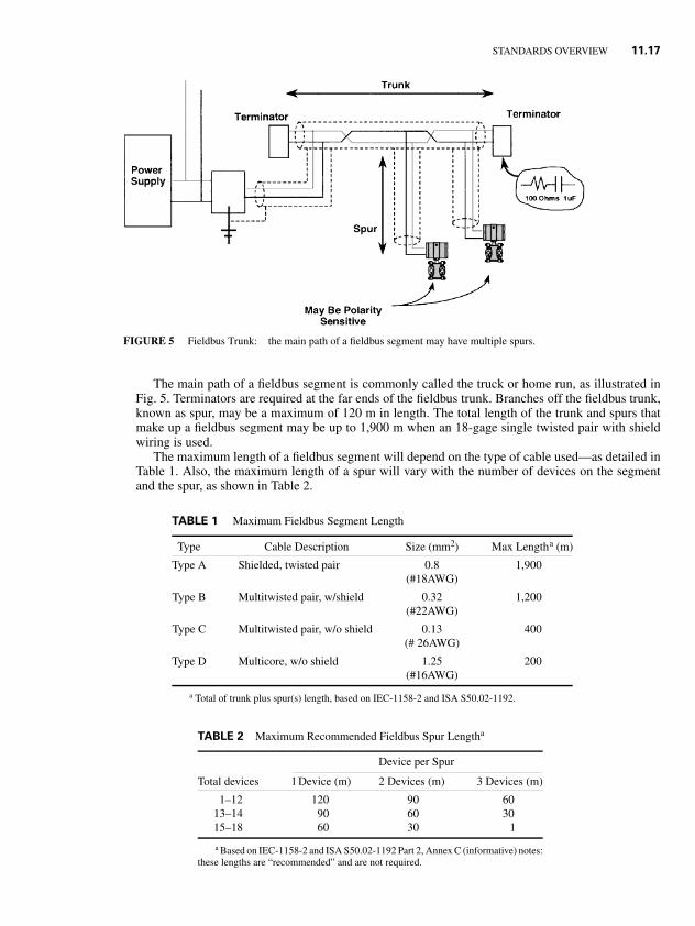
FIGURE 5 Fieldbus Trunk: the main path of a fieldbus segment may have multiple spurs.
The main path of a fieldbus segment is commonly called the truck or home run, as illustrated inFig. 5. Terminators are required at the far ends of the fieldbus trunk. Branches off the fieldbus trunk,known as spur, may be a maximum of 120 m in length. The total length of the trunk and spurs thatmake up a fieldbus segment may be up to 1,900 m when an 18-gage single twisted pair with shieldwiring is used.
The maximum length of a fieldbus segment will depend on the type of cable used—as detailed inTable 1. Also, the maximum length of a spur will vary with the number of devices on the segmentand the spur, as shown in Table 2.
TABLE 1 Maximum Fieldbus Segment Length
Type Cable Description Size (mm2) Max Lengtha (m)
Type A Shielded, twisted pair 0.8 1,900(#18AWG)
Type B Multitwisted pair, w/shield 0.32 1,200(#22AWG)
Type C Multitwisted pair, w/o shield 0.13 400(# 26AWG)
Type D Multicore, w/o shield 1.25 200(#16AWG)
a Total of trunk plus spur(s) length, based on IEC-1158-2 and ISA S50.02-1192.
TABLE 2 Maximum Recommended Fieldbus Spur Lengtha
Device per Spur
Total devices 1Device (m) 2 Devices (m) 3 Devices (m)
1–12 120 90 6013–14 90 60 3015–18 60 30 1
a Based on IEC-1158-2 and ISA S50.02-1192 Part 2, Annex C (informative) notes:these lengths are “recommended” and are not required.
1.8P1: xxx
31 August 1999 21:52 chap11.tex CHAP-11.SGM MH009v3(1999/07/12)
11.18 PROCESS/INDUSTRIAL INSTRUMENTS AND CONTROLS HANDBOOK
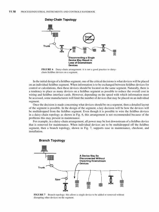
FIGURE 6 Daisy-chain arrangement: it is not a good practice to daisy-chain fieldbus devices on a segment.
In the initial design of a fieldbus segment, one of the critical decisions is what devices will be placedon an individual fieldbus segment. When information is to be exchanged between fieldbus devices forcontrol or calculations, then these devices should be located on the same segment. Naturally, there isa tendency to place as many devices on a fieldbus segment as possible to reduce the overall cost inwiring and fieldbus interface cards. However, depending on the speed with which information mustbe accessed, some manufacturers will limit the number of devices that may be placed on an individualsegment.
Once the decision is made concerning what devices should be on a segment, then a detailed layoutof the segment is possible. In the design of the segment, a key decision will be how the devices willbe multidropped from the fieldbus segment. Even though it is possible to wire the fieldbus devicesin a daisy-chain topology as shown in Fig. 6, this arrangement is not recommended because of theproblems this may present in maintenance.
For example, in a daisy-chain arrangement, all power may be lost downstream of a fieldbus devicethat is removed for maintenance. When individual devices are to be multidropped off the fieldbussegment, then a branch topology, shown in Fig. 7, supports ease in maintenance, checkout, andinstallation.
FIGURE 7 Branch topology: this allows a single device to be added or removed withoutdisrupting other devices on the segment.
1.8P1: xxx
31 August 1999 21:52 chap11.tex CHAP-11.SGM MH009v3(1999/07/12)
STANDARDS OVERVIEW 11.19
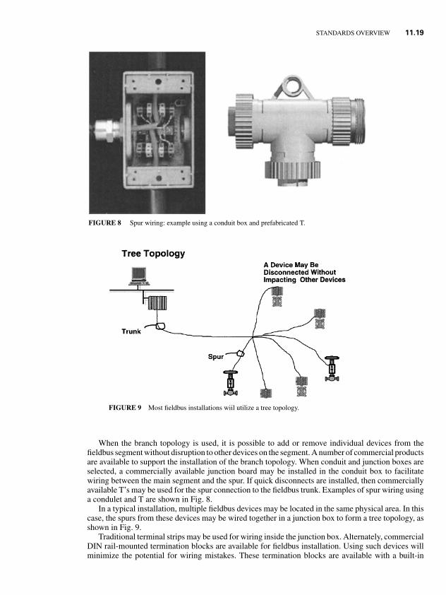
FIGURE 8 Spur wiring: example using a conduit box and prefabricated T.
FIGURE 9 Most fieldbus installations wiil utilize a tree topology.
When the branch topology is used, it is possible to add or remove individual devices from thefieldbus segment without disruption to other devices on the segment. A number of commercial productsare available to support the installation of the branch topology. When conduit and junction boxes areselected, a commercially available junction board may be installed in the conduit box to facilitatewiring between the main segment and the spur. If quick disconnects are installed, then commerciallyavailable T’s may be used for the spur connection to the fieldbus trunk. Examples of spur wiring usinga condulet and T are shown in Fig. 8.
In a typical installation, multiple fieldbus devices may be located in the same physical area. In thiscase, the spurs from these devices may be wired together in a junction box to form a tree topology, asshown in Fig. 9.
Traditional terminal strips may be used for wiring inside the junction box. Alternately, commercialDIN rail-mounted termination blocks are available for fieldbus installation. Using such devices willminimize the potential for wiring mistakes. These termination blocks are available with a built-in
1.8P1: xxx
31 August 1999 21:52 chap11.tex CHAP-11.SGM MH009v3(1999/07/12)
11.20 PROCESS/INDUSTRIAL INSTRUMENTS AND CONTROLS HANDBOOK
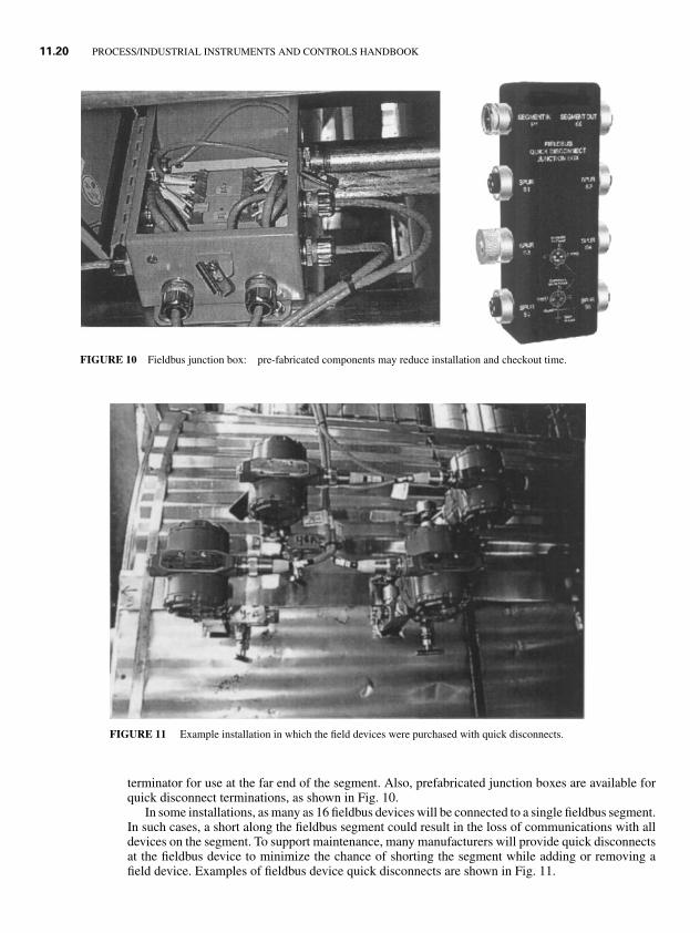
FIGURE 10 Fieldbus junction box: pre-fabricated components may reduce installation and checkout time.
FIGURE 11 Example installation in which the field devices were purchased with quick disconnects.
terminator for use at the far end of the segment. Also, prefabricated junction boxes are available forquick disconnect terminations, as shown in Fig. 10.
In some installations, as many as 16 fieldbus devices will be connected to a single fieldbus segment.In such cases, a short along the fieldbus segment could result in the loss of communications with alldevices on the segment. To support maintenance, many manufacturers will provide quick disconnectsat the fieldbus device to minimize the chance of shorting the segment while adding or removing afield device. Examples of fieldbus device quick disconnects are shown in Fig. 11.
1.8P1: xxx
31 August 1999 21:52 chap11.tex CHAP-11.SGM MH009v3(1999/07/12)
STANDARDS OVERVIEW 11.21
UTILIZING FIELDBUS DEVICES TO MEETAPPLICATION REQUIREMENTS
In a fieldbus environment, the user application is defined through the configuration of function blocks.This approach is similar to the configuration of control and monitoring in a distributed control system(DCS) today. However, the fieldbus function blocks support applications, which involve measurementand control, to be distributed between fieldbus devices. Such capability will allow the base level processcontrol and measurement done today in distributed control systems and single-loop digital controllersto be implemented in a fieldbus device. Some of the advantages gained by standardizing the userapplication are:
� consistent, easy, block-oriented configuration of functions� distribution and execution of function in field devices from different manufacturers in an integrated,
seamless manner� consistent definition of information that will be communicated and function that will be executed� avoidance of custom interfaces and cumbersome mapping
Monitoring, calculation, and control functions may be defined by configuring function blockswithin a fieldbus device and configuring the connections between function block input and outputparameters. Fieldbus devices provide a new level of capability. Fieldbus valve and transmitters maysupport control and calculations. In addition, auxiliary measurements such as stem position or limitswitch status for an on–off valve will often be made available through fieldbus.
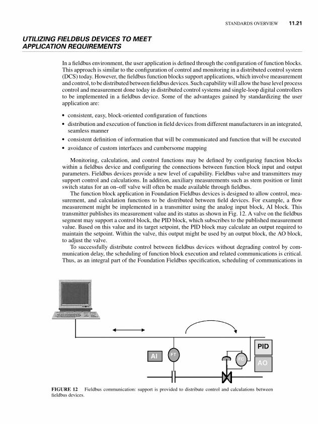
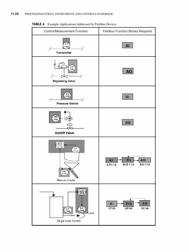
The function block application in Foundation Fieldbus devices is designed to allow control, mea-surement, and calculation functions to be distributed between field devices. For example, a flowmeasurement might be implemented in a transmitter using the analog input block, AI block. Thistransmitter publishes its measurement value and its status as shown in Fig. 12. A valve on the fieldbussegment may support a control block, the PID block, which subscribes to the published measurementvalue. Based on this value and its target setpoint, the PID block may calculate an output required tomaintain the setpoint. Within the valve, this output might be used by an output block, the AO block,to adjust the valve.
To successfully distribute control between fieldbus devices without degrading control by com-munication delay, the scheduling of function block execution and related communications is critical.Thus, as an integral part of the Foundation Fieldbus specification, scheduling of communications in
FIGURE 12 Fieldbus communication: support is provided to distribute control and calculations betweenfieldbus devices.
1.8P1: xxx
31 August 1999 21:52 chap11.tex CHAP-11.SGM MH009v3(1999/07/12)
11.22 PROCESS/INDUSTRIAL INSTRUMENTS AND CONTROLS HANDBOOK
FIGURE 13 Both control-related communication and function block execution may bescheduled to minimize delay.
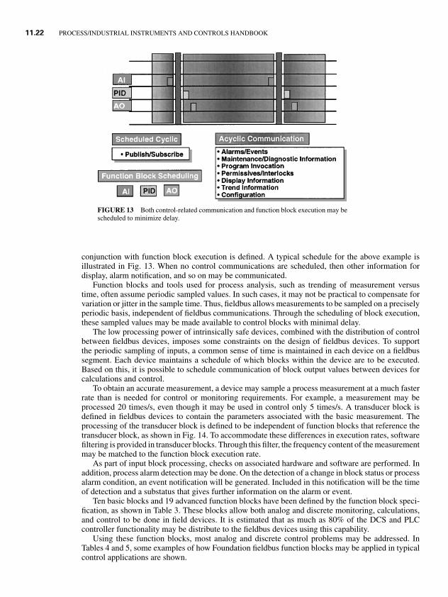
conjunction with function block execution is defined. A typical schedule for the above example isillustrated in Fig. 13. When no control communications are scheduled, then other information fordisplay, alarm notification, and so on may be communicated.
Function blocks and tools used for process analysis, such as trending of measurement versustime, often assume periodic sampled values. In such cases, it may not be practical to compensate forvariation or jitter in the sample time. Thus, fieldbus allows measurements to be sampled on a preciselyperiodic basis, independent of fieldbus communications. Through the scheduling of block execution,these sampled values may be made available to control blocks with minimal delay.
The low processing power of intrinsically safe devices, combined with the distribution of controlbetween fieldbus devices, imposes some constraints on the design of fieldbus devices. To supportthe periodic sampling of inputs, a common sense of time is maintained in each device on a fieldbussegment. Each device maintains a schedule of which blocks within the device are to be executed.Based on this, it is possible to schedule communication of block output values between devices forcalculations and control.
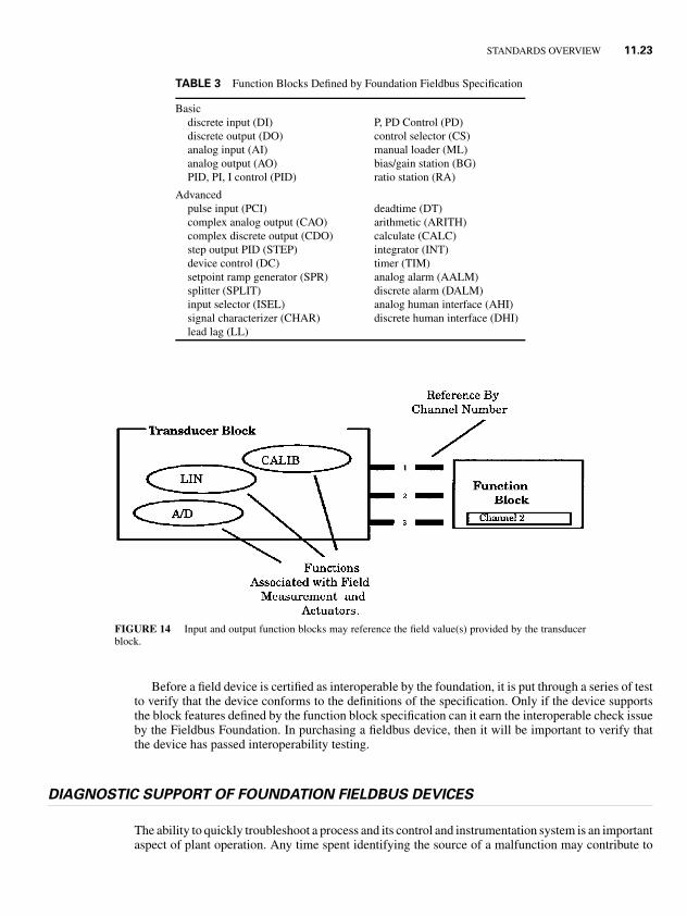
To obtain an accurate measurement, a device may sample a process measurement at a much fasterrate than is needed for control or monitoring requirements. For example, a measurement may beprocessed 20 times/s, even though it may be used in control only 5 times/s. A transducer block isdefined in fieldbus devices to contain the parameters associated with the basic measurement. Theprocessing of the transducer block is defined to be independent of function blocks that reference thetransducer block, as shown in Fig. 14. To accommodate these differences in execution rates, softwarefiltering is provided in transducer blocks. Through this filter, the frequency content of the measurementmay be matched to the function block execution rate.
As part of input block processing, checks on associated hardware and software are performed. Inaddition, process alarm detection may be done. On the detection of a change in block status or processalarm condition, an event notification will be generated. Included in this notification will be the timeof detection and a substatus that gives further information on the alarm or event.
Ten basic blocks and 19 advanced function blocks have been defined by the function block speci-fication, as shown in Table 3. These blocks allow both analog and discrete monitoring, calculations,and control to be done in field devices. It is estimated that as much as 80% of the DCS and PLCcontroller functionality may be distribute to the fieldbus devices using this capability.
Using these function blocks, most analog and discrete control problems may be addressed. InTables 4 and 5, some examples of how Foundation fieldbus function blocks may be applied in typicalcontrol applications are shown.
1.8P1: xxx
31 August 1999 21:52 chap11.tex CHAP-11.SGM MH009v3(1999/07/12)
STANDARDS OVERVIEW 11.23
TABLE 3 Function Blocks Defined by Foundation Fieldbus Specification
Basicdiscrete input (DI) P, PD Control (PD)discrete output (DO) control selector (CS)analog input (AI) manual loader (ML)analog output (AO) bias/gain station (BG)PID, PI, I control (PID) ratio station (RA)
Advancedpulse input (PCI) deadtime (DT)complex analog output (CAO) arithmetic (ARITH)complex discrete output (CDO) calculate (CALC)step output PID (STEP) integrator (INT)device control (DC) timer (TIM)setpoint ramp generator (SPR) analog alarm (AALM)splitter (SPLIT) discrete alarm (DALM)input selector (ISEL) analog human interface (AHI)signal characterizer (CHAR) discrete human interface (DHI)lead lag (LL)
FIGURE 14 Input and output function blocks may reference the field value(s) provided by the transducerblock.
Before a field device is certified as interoperable by the foundation, it is put through a series of testto verify that the device conforms to the definitions of the specification. Only if the device supportsthe block features defined by the function block specification can it earn the interoperable check issueby the Fieldbus Foundation. In purchasing a fieldbus device, then it will be important to verify thatthe device has passed interoperability testing.
DIAGNOSTIC SUPPORT OF FOUNDATION FIELDBUS DEVICES
The ability to quickly troubleshoot a process and its control and instrumentation system is an importantaspect of plant operation. Any time spent identifying the source of a malfunction may contribute to
1.8P1: xxx
31 August 1999 21:52 chap11.tex CHAP-11.SGM MH009v3(1999/07/12)
11.24 PROCESS/INDUSTRIAL INSTRUMENTS AND CONTROLS HANDBOOK
Control/Measurement Function
TABLE 4 Example Applications Addressed by Fieldbus Devices
Fieldbus Function Blocks Required

1.8P1: xxx
31 August 1999 21:52 chap11.tex CHAP-11.SGM MH009v3(1999/07/12)
STANDARDS OVERVIEW 11.25

1.8P1: xxx
31 August 1999 21:52 chap11.tex CHAP-11.SGM MH009v3(1999/07/12)
11.26 PROCESS/INDUSTRIAL INSTRUMENTS AND CONTROLS HANDBOOK
FIGURE 15 Input/Output status: each function block input or output supports a valueand status.
process downtime and lost production. In many digital control systems in use today, the processmeasurement is received as a 4–20 mA signal and the actuator is sent as a 4–20 mA signal. Plantinstrument technicians are familiar with the troubleshooting process instrumented in this manner.Within fieldbus devices the signal from the measurement element will be converted directly to itsdigital representation. The only accessible representation of the measurement will be the digitalvalue communicated over the fieldbus. Thus, the tools and techniques used in calibration, setup,commissioning, and troubleshooting will change. The design of any fieldbus system must address therequirements for process analysis through communicated values.
Features are included in the Fieldbus Foundation Specification for the support of process analysisand troubleshooting field problems. Special consideration is given to signal filtering and sampling toensure that the resulting digital values adequately represent the true process measurement. Conditionsdetected by the field device that would impact the validity of the measurement are made available asthe status of the digital value. To allow this information in a device to be used, an efficient mechanismis provided to access field device information without disrupting the control distributed between fielddevices.
As part of input block processing, checks on associated hardware and software are performed.Analog values will be transferred as floating point values in engineering units. The status of an outputparameter is calculated by the block to give an explicit indication of the quality of the value: good,uncertain, or bad as shown in Fig. 15. A substatus attribute indicates the primary condition, whichdetermines the quality. Also, there is an explicit indication in the status attribute of whether the valueis limited high or low. When a block input or output parameter is access for viewing at an operatorconsole, historian, or diagnostic tool, both the value and its associated status may be communicated.The quality information and its substatus may be useful in diagnosing the cause of a bad or uncertainmeasurement.
A substatus attribute of status indicates the primary condition that determines the quality. Thesubstatus for good quality provides additional information that may be needed for control or monitoringpurposes. For example, the good substatus for input blocks is defined to give further information onthe status of alarms that are defined for the block. As part of block definition, the processing andpropagation of the status is defined.
Communication support is provided for an explicit indication of stale data. Data are defined to bestale if the input value has not been updated since it was last read or if a value has been communicatedbut the value received is the last (old) value. Within a device, the input parameter status will be

1.8P1: xxx
31 August 1999 21:52 chap11.tex CHAP-11.SGM MH009v3(1999/07/12)
STANDARDS OVERVIEW 11.27
FIGURE 16 Diagnostic informtion may be obtained byusing trend objects supported by a fieldbus device.
set to bad—no communication if the value is stale for a specified time. When communications arere-established, then the input will again reflect the status of the output parameter.
When a block input or output parameter is access for viewing at an operator console, historian, ordiagnostic tool, both the value and its associated status may be communicated. The quality informationand its substatus may be useful in diagnosing the cause of a bad or uncertain measurement. To facilitatethe use of status information, the representation and meaning of quality and its associated substatushave been defined in the Foundation Fieldbus Specification.
When information is accessed for process analysis and diagnostics, it may not be practical ortechnically feasible to communicate individual parameter values as fast as the block executes rate. Toaddress these issues, trend objects are defined in fieldbus devices as illustrated in Fig. 16. At least onetrend object is included in each field device. A trend object maintains a collection of 16 parametersamples. Through trend-object configuration, it is possible to specify the input or output parameterto be collected at the collection rate. The block collects both the parameter value and status. Samplesrates are an integer multiple of the parameter’s block execution rate. Sample values may be averagedif the collection rate is slower than the block execution rate.
When 16 new samples are collected, this information along with the time stamp of the last valuecollected will be automatically reported to one or more devices. Through this mechanism, the com-munication load associated with the collection of the parameter value and status may be reduced by asmuch as a factor of 16. In addition, by collecting samples at the device, the collection of informationis not skewed or limited by the communication rate of the fieldbus.
View objects are provided for each function block to facilitate information access. A view objectallows multiple parameters to be read or written with a single communication request. Through thismechanism, communications to support updating operator interfaces (etc.) may be done efficiently.The processing of such requests is done when no other communications are scheduled. In addition,process alarm detection may be done in the fieldbus device. On the detection of a change in blockstatus or process alarm condition, an event notification will be generated. Included in this notifica-tion will be the time of detection and a substatus, which gives further information on the alarm orevent.
CONTROL SYSTEM IMPACT
A new generation of control systems that is designed to effectively utilize fieldbus devices is availablefrom major control system vendors. Such systems are smaller in size physically because of thereduction in the number of I/O card required to interface with field devices. To allow the configurationand calculated parameter values in a fieldbus device to be accessed, each manufacturer will providea device description (DD) of his or her fieldbus devices written in the device description language(DDL) standardized by the Fieldbus Foundation. Configuration and operator interface stations, which
1.8P1: xxx
31 August 1999 21:52 chap11.tex CHAP-11.SGM MH009v3(1999/07/12)
11.28 PROCESS/INDUSTRIAL INSTRUMENTS AND CONTROLS HANDBOOK
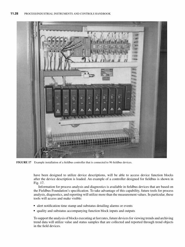
FIGURE 17 Example installation of a fieldbus controller that is connected to 96 fieldbus devices.
have been designed to utilize device descriptions, will be able to access device function blocksafter the device description is loaded. An example of a controller designed for fieldbus is shown inFig. 17.
Information for process analysis and diagnostics is available in fieldbus devices that are based onthe Fieldbus Foundation’s specification. To take advantage of this capability, future tools for processanalysis, diagnostics, and reporting will utilize more than the measurement values. In particular, thesetools will access and make visible:
� alert notification time stamp and substatus detailing alarms or events� quality and substatus accompanying function block inputs and outputs
To support the analysis of blocks executing at fast rates, future devices for viewing trends and archivingtrend data will utilize value and status samples that are collected and reported through trend objectsin the field devices.
1.8P1: xxx
31 August 1999 21:52 chap11.tex CHAP-11.SGM MH009v3(1999/07/12)
STANDARDS OVERVIEW 11.29
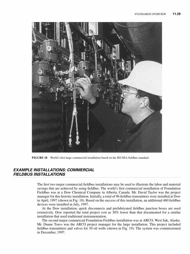
FIGURE 18 World’s first large commercial installation based on the IEC/ISA fieldbus standard.
EXAMPLE INSTALLATIONS: COMMERCIALFIELDBUS INSTALLATIONS
The first two major commercial fieldbus installations may be used to illustrate the labor and materialsavings that are achieved by using fieldbus. The world’s first commercial installation of FoundationFieldbus was at a Dow Chemical Company in Alberta, Canada. Mr. David Taylor was the projectmanager for this historic installation. Initially, a total of 96 fieldbus transmitters were installed at Dowin April, 1997 (shown in Fig. 18). Based on the success of this installation, an additional 480 fieldbusdevices were installed in July, 1997.
At the Dow installation, quick disconnects and prefabricated fieldbus junction boxes are usedextensively. Dow reported the total project cost as 30% lower than that documented for a similarinstallation that used traditional instrumentation.
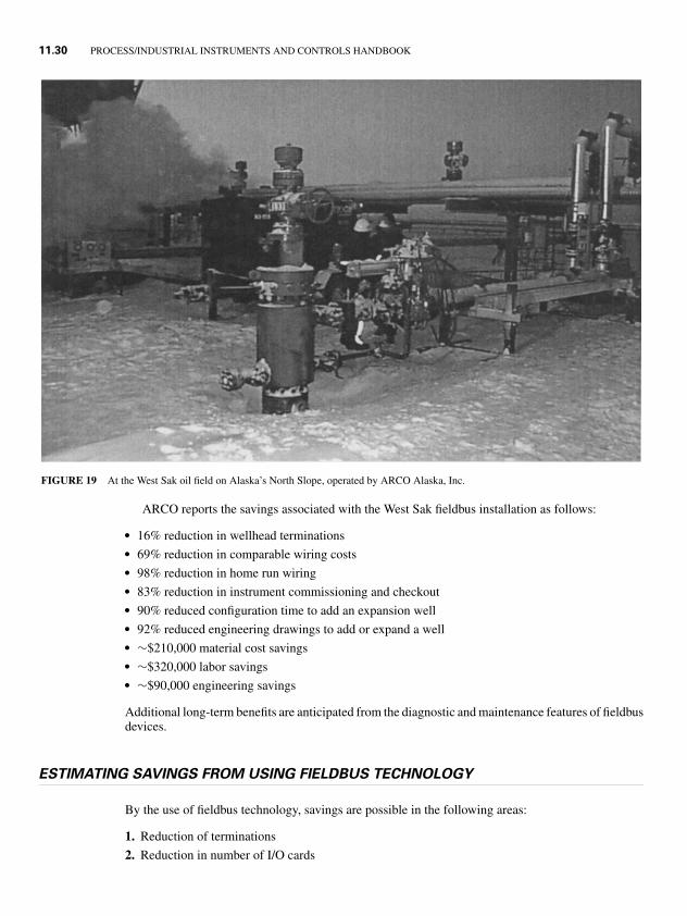
The second major commercial Foundation Fieldbus installation was at ARCO, West Sak, Alaska.Mr. Duane Toavs was the ARCO project manager for the large installation. This project includedfieldbus transmitters and valves for 30 oil wells (shown in Fig. 19). The system was commissionedin December, 1997.
1.8P1: xxx
31 August 1999 21:52 chap11.tex CHAP-11.SGM MH009v3(1999/07/12)
11.30 PROCESS/INDUSTRIAL INSTRUMENTS AND CONTROLS HANDBOOK
FIGURE 19 At the West Sak oil field on Alaska’s North Slope, operated by ARCO Alaska, Inc.
ARCO reports the savings associated with the West Sak fieldbus installation as follows:
� 16% reduction in wellhead terminations� 69% reduction in comparable wiring costs� 98% reduction in home run wiring� 83% reduction in instrument commissioning and checkout� 90% reduced configuration time to add an expansion well� 92% reduced engineering drawings to add or expand a well� ∼$210,000 material cost savings� ∼$320,000 labor savings� ∼$90,000 engineering savings
Additional long-term benefits are anticipated from the diagnostic and maintenance features of fieldbusdevices.
ESTIMATING SAVINGS FROM USING FIELDBUS TECHNOLOGY
By the use of fieldbus technology, savings are possible in the following areas:
1. Reduction of terminations
2. Reduction in number of I/O cards
1.8P1: xxx
31 August 1999 21:52 chap11.tex CHAP-11.SGM MH009v3(1999/07/12)
STANDARDS OVERVIEW 11.31
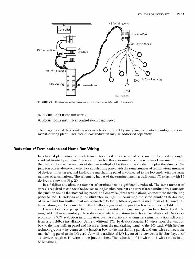
FIGURE 20 Illustration of terminations for a traditional I/O with 16 devices.
3. Reduction in home run wiring
4. Reduction in instrument control room panel space
The magnitude of these cost savings may be determined by analyzing the controls configuration in amanufacturing plant. Each area of cost reduction may be addressed separately.
Reduction of Terminations and Home Run Wiring
In a typical plant situation, each transmitter or valve is connected to a junction box with a single,shielded twisted pair, wire. Since each wire has three terminations, the number of terminations intothe junction box is the number of devices multiplied by three (two conductors plus the shield). Thejunction box is often connected to a marshalling panel with the same number of terminations (numberof devices times three), and finally, the marshalling panel is connected to the I/O cards with the samenumber of terminations. The schematic layout of the terminations in a traditional I/O system with 16devices is shown in Fig. 20.
In a fieldbus situation, the number of terminations is significantly reduced. The same number ofwires is required to connect the devices to the junction box, but one wire (three terminations) connectsthe junction box to the marshalling panel, and one wire (three terminations) connects the marshallingpanel to the H1 fieldbus card, as illustrated in Fig. 21. Assuming the same number (16 devices)of valves and transmitters that are connected to the fieldbus segment, a maximum of 16 wires (48terminations) can be connected to the fieldbus segment at the junction box, as shown in Table 6.
From a total cost perspective, a tremendous installation cost savings can be achieved with theusage of fieldbus technology. The reduction of 240 terminations to 60 for an installation of 16 devicesrepresents a 75% reduction in termination cost. A significant savings in wiring reduction will resultfrom any fieldbus installation. Using traditional I/O, 16 devices require 16 wires from the junctionbox to the marshalling panel and 16 wires from the marshalling panel to the I/O card. With fieldbustechnology, one wire connects the junction box to the marshalling panel, and one wire connects themarshalling panel to the I/O card. As with a traditional I/O layout of 16 devices, a fieldbus layout of16 devices requires 16 wires to the junction box. The reduction of 16 wires to 1 wire results in an83% reduction.
1.8P1: xxx
31 August 1999 21:52 chap11.tex CHAP-11.SGM MH009v3(1999/07/12)
11.32 PROCESS/INDUSTRIAL INSTRUMENTS AND CONTROLS HANDBOOK
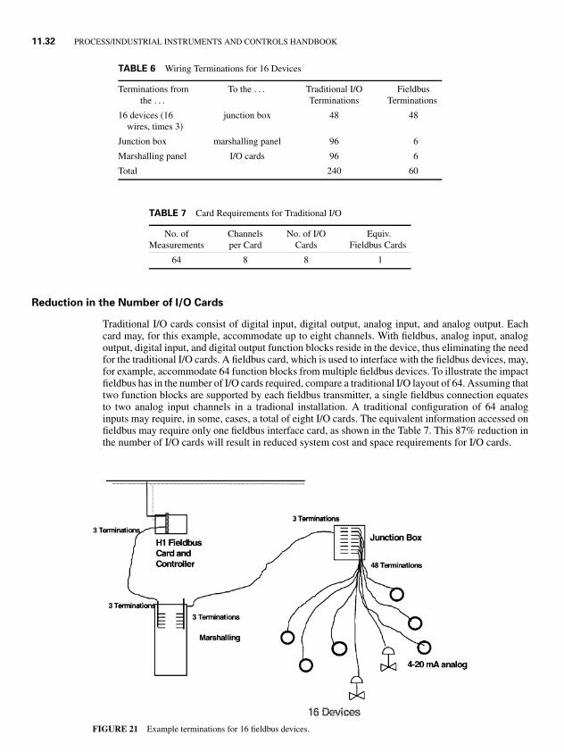
TABLE 6 Wiring Terminations for 16 Devices
Terminations from To the . . . Traditional I/O Fieldbusthe . . . Terminations Terminations
16 devices (16 junction box 48 48wires, times 3)
Junction box marshalling panel 96 6
Marshalling panel I/O cards 96 6
Total 240 60
TABLE 7 Card Requirements for Traditional I/O
No. of Channels No. of I/O Equiv.Measurements per Card Cards Fieldbus Cards
64 8 8 1
Reduction in the Number of I/O Cards
Traditional I/O cards consist of digital input, digital output, analog input, and analog output. Eachcard may, for this example, accommodate up to eight channels. With fieldbus, analog input, analogoutput, digital input, and digital output function blocks reside in the device, thus eliminating the needfor the traditional I/O cards. A fieldbus card, which is used to interface with the fieldbus devices, may,for example, accommodate 64 function blocks from multiple fieldbus devices. To illustrate the impactfieldbus has in the number of I/O cards required, compare a traditional I/O layout of 64. Assuming thattwo function blocks are supported by each fieldbus transmitter, a single fieldbus connection equatesto two analog input channels in a tradional installation. A traditional configuration of 64 analoginputs may require, in some, cases, a total of eight I/O cards. The equivalent information accessed onfieldbus may require only one fieldbus interface card, as shown in the Table 7. This 87% reduction inthe number of I/O cards will result in reduced system cost and space requirements for I/O cards.
FIGURE 21 Example terminations for 16 fieldbus devices.
1.8P1: xxx
31 August 1999 21:52 chap11.tex CHAP-11.SGM MH009v3(1999/07/12)
STANDARDS OVERVIEW 11.33
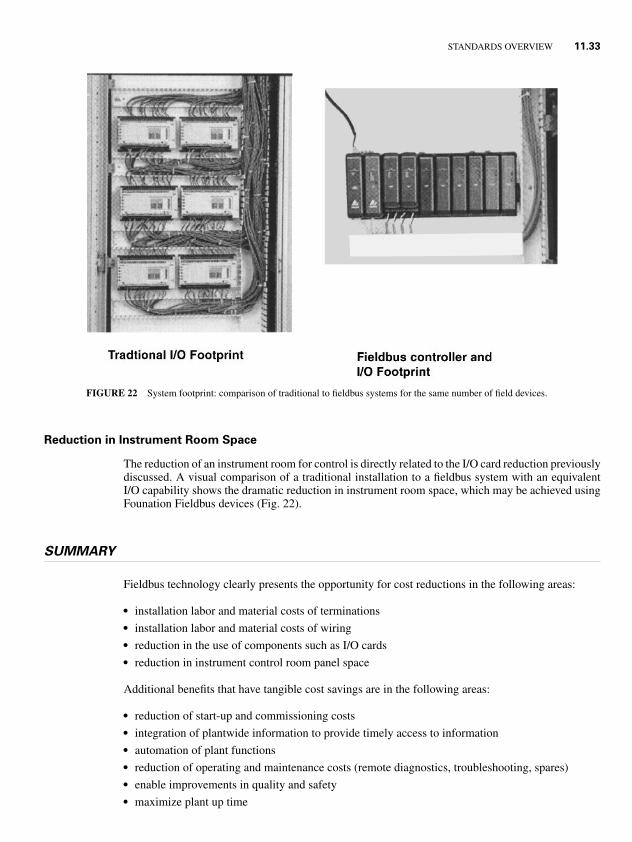
FIGURE 22 System footprint: comparison of traditional to fieldbus systems for the same number of field devices.
Reduction in Instrument Room Space
The reduction of an instrument room for control is directly related to the I/O card reduction previouslydiscussed. A visual comparison of a traditional installation to a fieldbus system with an equivalentI/O capability shows the dramatic reduction in instrument room space, which may be achieved usingFounation Fieldbus devices (Fig. 22).
SUMMARY
Fieldbus technology clearly presents the opportunity for cost reductions in the following areas:
� installation labor and material costs of terminations� installation labor and material costs of wiring� reduction in the use of components such as I/O cards� reduction in instrument control room panel space
Additional benefits that have tangible cost savings are in the following areas:
� reduction of start-up and commissioning costs� integration of plantwide information to provide timely access to information� automation of plant functions� reduction of operating and maintenance costs (remote diagnostics, troubleshooting, spares)� enable improvements in quality and safety� maximize plant up time
1.8P1: xxx
31 August 1999 21:52 chap11.tex CHAP-11.SGM MH009v3(1999/07/12)
11.34 PROCESS/INDUSTRIAL INSTRUMENTS AND CONTROLS HANDBOOK
It is too early to have hard numbers on the long-term benefit that the diagnostic and maintenancefeature of fieldbus devices will provide these initial Foundation Fieldbus installations. However, thefeeling of plants that have installed fieldbus is that these savings will match or exceed the installationsavings that fieldbus has provided.
Best Practices in Applying Fieldbus
1. Limit the number of fieldbus devices on a single fieldbus segment to 16. This will help ensurereasonable update rates of dynamic fieldbus parameters in the host interface.
2. Install on a single fieldbus segment no more than 12 fieldbus devices that are powered by thefieldbus segment. For an intrinsically safe installation, limit the maximum to four to six devicesbased on individual device power consumption.
3. Locate fieldbus devices on a single segment if control or calculations are distributed betweenthese fieldbus devices.
4. Utilize a tree topology whenever possible for connecting fieldbus devices to a segment. Avoiddaisy-chaining fieldbus devices since this will cause installation, commissioning, and maintenanceproblems.
5. Locate field junction boxes within 120 m of fieldbus devices that are to be on a fieldbus segment.
6. Install an approved barrier with the fieldbus power supply when fieldbus devices are to be installedin a classified area and the fieldbus segment is not protected by hard conduit or other approvedmaterials.
7. Limit the fieldbus segment length to 1,900 m when using Type A cable (shielded twisted pair;0.8 mm2).
8. Utilize a maximum of 16 function block input and output links between fieldbus devices ona single segment to provide reasonable loop execution rates and display update time at ahost.
9. Purchase fieldbus devices that have been certified by the Fieldbus Foundation to be interoperable.Consider the function blocks and diagnostics supported by the fieldbus device when selecting afieldbus device.
10. Select a control system that is specifically designed to support the interface, configuration, anddiagnostics of fieldbus devices. In particular, the configuration system should utilize the DDprovided by the device manufacturer to allow all fieldbus block parameters of a device to beaccessed.
11. Include the location of power conditioners and terminators on fieldbus segment drawings andverify their installation before initially powering up the segment.
12. Continue shields throughout the fieldbus segment and have only one ground reference—at thesource of power.
13. Estimate terminations and a wire reduction of 70–80% when 16 fieldbus devices are installed oneach segment.
14. Plan on an 80–90% reduction in the number of I/O cards when 16 devices are included on afieldbus segment. However, the cost of a fieldbus interface card may be higher than a traditionalI/O card.
15. Take advantage of the fact that the rack room space for a complete fieldbus installation with16 devices per segment will typically require only 30% of the space needed for a traditionalinstallation.
16. Consider the fact that some projects have reported an 80–90% deduction in time for instrumen-tation drawings and instrument commissioning and checkout time over a traditional installationusing fieldbus. However, on your first installation in a plant, plan on some of these savings beingoffset by additional time spent on fieldbus training.
1.8P1: xxx
31 August 1999 21:52 chap11.tex CHAP-11.SGM MH009v3(1999/07/12)
STANDARDS OVERVIEW 11.35
REFERENCES
1. Blevins, T., “Fieldbus Ushers In A New Era in Process Control,” Plant Services, September 1998.
2. Blevins, T., J. Duffy, and R. Willems, “DCS Integration of Fieldbus,” ISA Conf. proceedings, 1996.
3. Blevins, T., and W. Wojsznis, “Fieldbus Support for Process Analysis,” ISA Trans. Vol. 35, pp. 177–183, 1996.
4. Instrument Society of America, “User Layer Technical Report for the Fieldbus Standard,” ISA-TR50.02, Part9-TR1, Tech. Rep. ISA/SP50-1993-389F, 1993.
5. Furness, H., “Distributed Control Functionality Moves Downstream,” Control Engineering, December 1993.
6. International Electrotechnical Commission, Technical Committee No. 65, Industrial-Process Measurementand Control, Working Group 6, Committee Draft: Function Blocks for Industrial-Process Measurement andControl Systems, Part 1—General Requirements.
7. Fieldbus Foundation, Fieldbus Specification, Function Block Application Process—Part 1&2, FF-94-890, FF-94-8891.
8. Bialkowski, W. L., and A. D. Weldon, “The Digital Future of Process Control: Possibilities, Limitations, andRamifications,” Tappi Journal, Vol. 77, No. 10, October 1994.
9. Wheelis, J. D., and K. Zech, “Benefits Observed During Field Trials of an Interoperable Fieldbus,” ISA Conf.Proceedings, 1994.
BATCH CONTROL: APPLYINGTHE S88.01 STANDARD
by Thomas G. Fisher∗
INTRODUCTION
The S88.01 standard [1] provides the basis for an object-oriented approach that fits very well withbatch control and the automation of batch processes, including the development of objects that canbe reused from project to project. Significant savings from applying these standards and guidelineshave been demonstrated in many phases of batch control projects. Considerable emphasis is given inthe standard to the separation of the recipe procedure (which tells how a batch should be made) fromthe equipment logic (which actually executes the batch). This separation is one of the major reasonsthat this standard has been so successful.
S88.01 is entitled Models and Terminology, but it is really a communications standard, althoughnot in the sense of communications protocols over a local area network. S88.01 makes it possible forpeople to communicate about batch control by using a common language and a common set of modelsthat describe batch control and batch manufacturing. S88.01, Part 1– Models and Terminology, wasapproved in February 1995. S88.01 became a joint ANSI (American National Standards Institute) andISA (International Society for Measurement and Control) standard in October 1995. IEC 61512 [2]is a corresponding international standard from IEC (the International Electrotechnical Commission).
The NAMUR NE-33 guidelines [3] is often referenced in discussions about batch control. NAMURis a group of German user companies, and it was founded in 1949 as an association of the measuringand control engineering departments of the chemical industry. Working Group 6, Batch Control, wasfounded in 1966. The first official attempt to set criteria and guidelines for batch automation and
* Operations Technology Manager, Lubrizol Corporation, Wickliffe, Ohio.
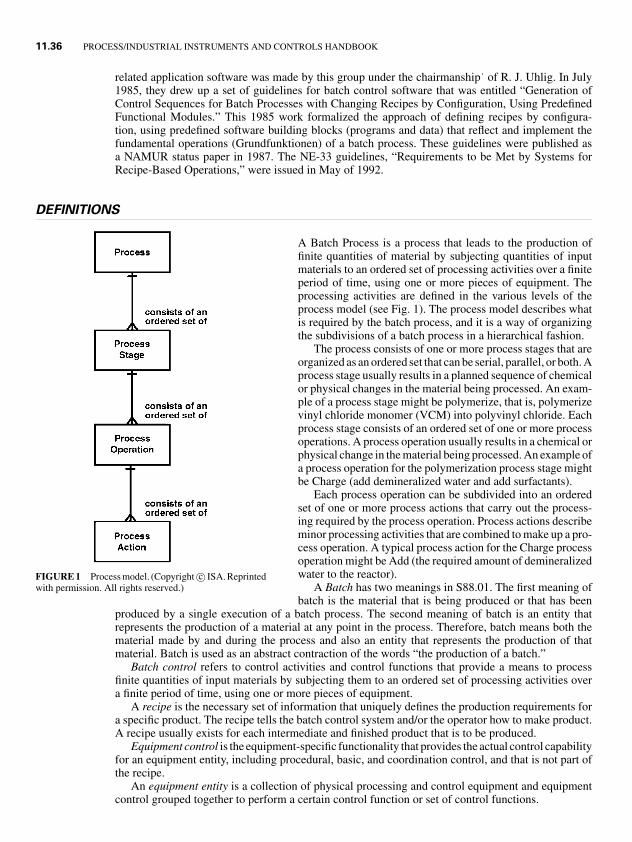
1.8P1: xxx
31 August 1999 21:52 chap11.tex CHAP-11.SGM MH009v3(1999/07/12)
11.36 PROCESS/INDUSTRIAL INSTRUMENTS AND CONTROLS HANDBOOK
related application software was made by this group under the chairmanship˙ of R. J. Uhlig. In July1985, they drew up a set of guidelines for batch control software that was entitled “Generation ofControl Sequences for Batch Processes with Changing Recipes by Configuration, Using PredefinedFunctional Modules.” This 1985 work formalized the approach of defining recipes by configura-tion, using predefined software building blocks (programs and data) that reflect and implement thefundamental operations (Grundfunktionen) of a batch process. These guidelines were published asa NAMUR status paper in 1987. The NE-33 guidelines, “Requirements to be Met by Systems forRecipe-Based Operations,” were issued in May of 1992.
DEFINITIONS
FIGURE 1 Process model. (Copyright c© ISA. Reprintedwith permission. All rights reserved.)
A Batch Process is a process that leads to the production offinite quantities of material by subjecting quantities of inputmaterials to an ordered set of processing activities over a finiteperiod of time, using one or more pieces of equipment. Theprocessing activities are defined in the various levels of theprocess model (see Fig. 1). The process model describes whatis required by the batch process, and it is a way of organizingthe subdivisions of a batch process in a hierarchical fashion.
The process consists of one or more process stages that areorganized as an ordered set that can be serial, parallel, or both. Aprocess stage usually results in a planned sequence of chemicalor physical changes in the material being processed. An exam-ple of a process stage might be polymerize, that is, polymerizevinyl chloride monomer (VCM) into polyvinyl chloride. Eachprocess stage consists of an ordered set of one or more processoperations. A process operation usually results in a chemical orphysical change in the material being processed. An example ofa process operation for the polymerization process stage mightbe Charge (add demineralized water and add surfactants).
Each process operation can be subdivided into an orderedset of one or more process actions that carry out the process-ing required by the process operation. Process actions describeminor processing activities that are combined to make up a pro-cess operation. A typical process action for the Charge processoperation might be Add (the required amount of demineralizedwater to the reactor).
A Batch has two meanings in S88.01. The first meaning ofbatch is the material that is being produced or that has been
produced by a single execution of a batch process. The second meaning of batch is an entity thatrepresents the production of a material at any point in the process. Therefore, batch means both thematerial made by and during the process and also an entity that represents the production of thatmaterial. Batch is used as an abstract contraction of the words “the production of a batch.”
Batch control refers to control activities and control functions that provide a means to processfinite quantities of input materials by subjecting them to an ordered set of processing activities overa finite period of time, using one or more pieces of equipment.
A recipe is the necessary set of information that uniquely defines the production requirements fora specific product. The recipe tells the batch control system and/or the operator how to make product.A recipe usually exists for each intermediate and finished product that is to be produced.
Equipment control is the equipment-specific functionality that provides the actual control capabilityfor an equipment entity, including procedural, basic, and coordination control, and that is not part ofthe recipe.
An equipment entity is a collection of physical processing and control equipment and equipmentcontrol grouped together to perform a certain control function or set of control functions.
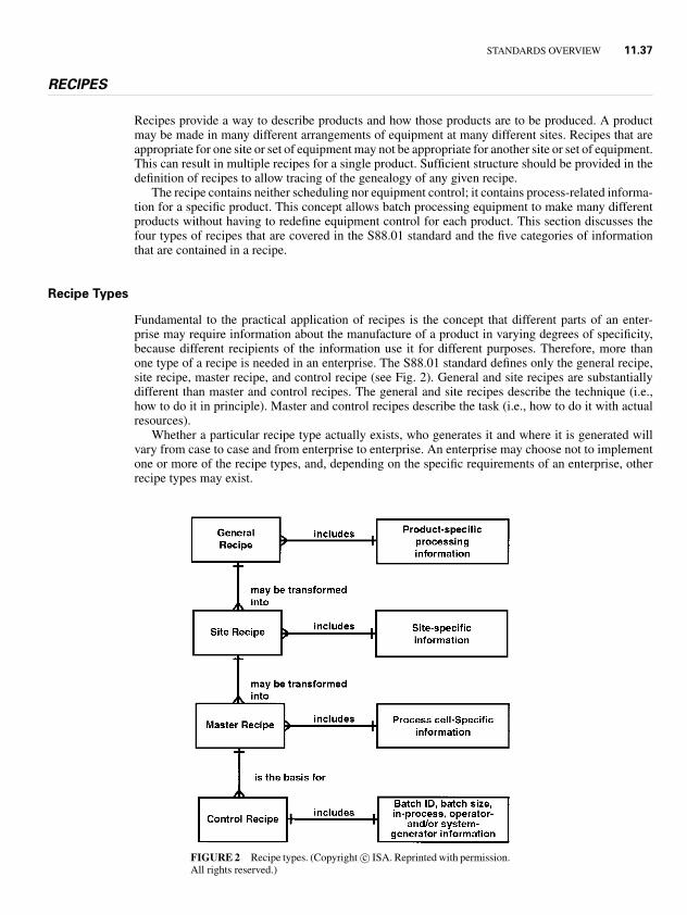
1.8P1: xxx
31 August 1999 21:52 chap11.tex CHAP-11.SGM MH009v3(1999/07/12)
STANDARDS OVERVIEW 11.37
RECIPES
Recipes provide a way to describe products and how those products are to be produced. A productmay be made in many different arrangements of equipment at many different sites. Recipes that areappropriate for one site or set of equipment may not be appropriate for another site or set of equipment.This can result in multiple recipes for a single product. Sufficient structure should be provided in thedefinition of recipes to allow tracing of the genealogy of any given recipe.
The recipe contains neither scheduling nor equipment control; it contains process-related informa-tion for a specific product. This concept allows batch processing equipment to make many differentproducts without having to redefine equipment control for each product. This section discusses thefour types of recipes that are covered in the S88.01 standard and the five categories of informationthat are contained in a recipe.
Recipe Types
Fundamental to the practical application of recipes is the concept that different parts of an enter-prise may require information about the manufacture of a product in varying degrees of specificity,because different recipients of the information use it for different purposes. Therefore, more thanone type of a recipe is needed in an enterprise. The S88.01 standard defines only the general recipe,site recipe, master recipe, and control recipe (see Fig. 2). General and site recipes are substantiallydifferent than master and control recipes. The general and site recipes describe the technique (i.e.,how to do it in principle). Master and control recipes describe the task (i.e., how to do it with actualresources).
Whether a particular recipe type actually exists, who generates it and where it is generated willvary from case to case and from enterprise to enterprise. An enterprise may choose not to implementone or more of the recipe types, and, depending on the specific requirements of an enterprise, otherrecipe types may exist.
FIGURE 2 Recipe types. (Copyright c© ISA. Reprinted with permission.All rights reserved.)
1.8P1: xxx
31 August 1999 21:52 chap11.tex CHAP-11.SGM MH009v3(1999/07/12)
11.38 PROCESS/INDUSTRIAL INSTRUMENTS AND CONTROLS HANDBOOK
General Recipes. A general recipe is the parent of all lower-level recipes. A general recipe providesgeneral manufacturing requirements in an equipment-independent format, and it applies to all siteswithin the enterprise.
Site Recipes. A site recipe is specific to a particular manufacturing site within the enterprise. A siterecipe is derived from a general recipe, and little transformation is typically required. A site recipe isalso in an equipment-independent format, and it is generally used for the following:
� planning� costing� long-term production scheduling
Master Recipes. A master recipe is derived from a site recipe, and a major transformation is expectedto be required because the master recipe is specific to equipment at the manufacturing site. A masterrecipe may be targeted at a class of equipment or to specific pieces of equipment. Master recipescontain information that is needed for batch scheduling.
Control Recipes. A control recipe starts its life as a copy of a master recipe, and it is the recipethat is used to make a batch of product, whether automatically by a control system or manually by anoperator. A control recipe is specific to a particular batch of product, and it may change as the batchprogresses.
Recipe Information Categories
Recipes contain the following categories of information: header, formula, procedure, equipmentrequirements and other information. The following discussion provides details regarding these cate-gories.
Header. The administrative information in the recipe is referred to as the header. Typical headerinformation may include the recipe and product identification, the version number, the originator,the issue date, approvals, status and other administrative information. For example, a site recipe maycontain the name and version of the general recipe from which it was created.
Formula. The formula is a category of recipe information that includes process inputs, processparameters, and process outputs.
A process input is the identification and quantity of a raw material or other resource that isrequired to make the product. In addition to raw materials that are consumed in the batch processin the manufacture of a product, process inputs may also include energy and other resources (e.g.,manpower). Process inputs consist of both the name of the resource and the amount required to makea specific quantity of product. Quantities may be specified as absolute values or as equations basedupon other formula parameters or the batch or equipment size. Process inputs may specify allowablesubstitutions, and they are expressed in the same basic form.
A process parameter details information such as temperature, pressure, or time that is pertinent tothe product but that does not fall into the classification of input or output. Process parameters may beused as set points, comparison values, or in conditional logic.
A process output is the identification and quantity of a material and/or energy that is expectedto result from one execution of the recipe. These data may detail environmental impact, and theymay also contain other information (e.g., specification of the intended outputs in terms of quantity,labeling, and yield).
The types of formula data are distinguished to provide information to different parts of an enterprise,and they have to be available without the clutter of processing details. For example, the list of processinputs may be presented as a condensed list of ingredients for the recipe or as a set of individualingredients for each appropriate procedural element in a recipe.
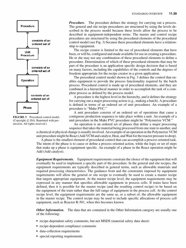
1.8P1: xxx
31 August 1999 21:52 chap11.tex CHAP-11.SGM MH009v3(1999/07/12)
STANDARDS OVERVIEW 11.39
FIGURE 3 Procedural control model.(Copyright c© ISA. Reprinted with per-mission. All rights reserved.)
Procedure. The procedure defines the strategy for carrying out a process.The general and site recipe procedures are structured by using the levels de-scribed in the process model because these levels allow the process to bedescribed in equipment-independent terms. The master and control recipeprocedures are structured by using the procedural elements of the proceduralcontrol model (see Fig. 3) because these procedural elements have a relation-ship to equipment.
The recipe creator is limited to the use of procedural elements that havebeen, or will be, configured and made available for use in creating a procedure.He or she may use any combination of these procedural elements to define aprocedure. Determination of which of these procedural elements that may bepart of the procedure is an application specific design decision that is basedon many factors, including the capabilities of the controls and the degrees offreedom appropriate for the recipe creator in a given application.
The procedural control model shown in Fig. 3 defines the control that en-ables equipment to provide the process functionality required by the batchprocess. Procedural control is made up of procedural elements, and they arecombined in a hierarchical manner in order to accomplish the task of a com-plete process as defined by the process model.
A procedure is the highest level in the hierarchy, and it defines the strategyfor carrying out a major processing action (e.g., making a batch). A procedureis defined in terms of an ordered set of unit procedures. An example of aprocedure is “Make PVC.”
A unit procedure consists of an ordered set of operations that cause acontiguous production sequence to take place within a unit. An example of aunit procedure in the Make PVC procedure might be “Polymerize VCM.”
An operation is an ordered set of phases that define a major processingsequence that takes the material being processed from one state to another, and
a chemical or physical change is usually involved. An example of an operation in the Polymerize VCMunit procedure might be React (Add VCM and catalyst, Heat, and Wait for the reactor pressure to drop).
A phase is the smallest element of procedural control that can accomplish a process oriented task.The intent of the phase is to cause or define a process oriented action, while the logic or set of stepsthat make up a phase is equipment specific. An example of a phase in the React operation might beAdd (Add catalyst).
Equipment Requirements. Equipment requirements constrain the choice of the equipment that willeventually be used to implement a specific part of the procedure. In the general and site recipes, theequipment requirements are typically described in general terms, such as allowable materials andrequired processing characteristics. The guidance from and the constraints imposed by equipmentrequirements will allow the general or site recipe to eventually be used to create a master recipethat targets appropriate equipment. At the master recipe level, the equipment requirements may beexpressed in any manner that specifies allowable equipment in process cells. If trains have beendefined, then it is possible for the master recipe (and the resulting control recipe) to be based onthe equipment of the train rather than the full range of equipment in the process cell. At the controlrecipe level, the equipment requirements are the same as, or a subset of, the allowable equipmentin the master recipe. The control recipe may be used to include specific allocations of process cellequipment, such as Reactor R-501, when this becomes known.
Other Information. The data that are contained in the Other Information category are usually oneof the following:
� recipe-dependent safety comments, but not MSDS (material safety data sheet)� recipe-dependent compliance comments� data-collection requirements� special reporting requirements
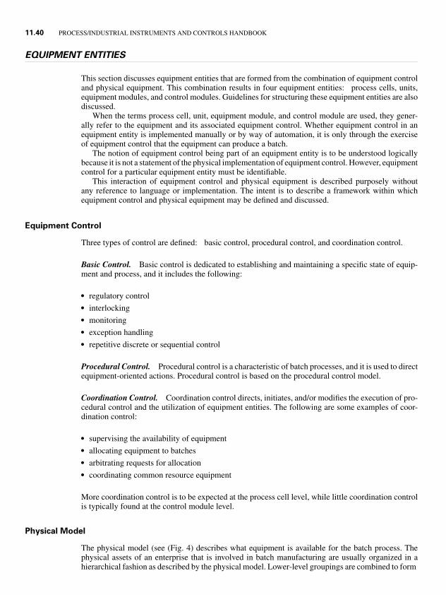
1.8P1: xxx
31 August 1999 21:52 chap11.tex CHAP-11.SGM MH009v3(1999/07/12)
11.40 PROCESS/INDUSTRIAL INSTRUMENTS AND CONTROLS HANDBOOK
EQUIPMENT ENTITIES
This section discusses equipment entities that are formed from the combination of equipment controland physical equipment. This combination results in four equipment entities: process cells, units,equipment modules, and control modules. Guidelines for structuring these equipment entities are alsodiscussed.
When the terms process cell, unit, equipment module, and control module are used, they gener-ally refer to the equipment and its associated equipment control. Whether equipment control in anequipment entity is implemented manually or by way of automation, it is only through the exerciseof equipment control that the equipment can produce a batch.
The notion of equipment control being part of an equipment entity is to be understood logicallybecause it is not a statement of the physical implementation of equipment control. However, equipmentcontrol for a particular equipment entity must be identifiable.
This interaction of equipment control and physical equipment is described purposely withoutany reference to language or implementation. The intent is to describe a framework within whichequipment control and physical equipment may be defined and discussed.
Equipment Control
Three types of control are defined: basic control, procedural control, and coordination control.
Basic Control. Basic control is dedicated to establishing and maintaining a specific state of equip-ment and process, and it includes the following:
� regulatory control� interlocking� monitoring� exception handling� repetitive discrete or sequential control
Procedural Control. Procedural control is a characteristic of batch processes, and it is used to directequipment-oriented actions. Procedural control is based on the procedural control model.
Coordination Control. Coordination control directs, initiates, and/or modifies the execution of pro-cedural control and the utilization of equipment entities. The following are some examples of coor-dination control:
� supervising the availability of equipment� allocating equipment to batches� arbitrating requests for allocation� coordinating common resource equipment
More coordination control is to be expected at the process cell level, while little coordination controlis typically found at the control module level.
Physical Model
The physical model (see (Fig. 4) describes what equipment is available for the batch process. Thephysical assets of an enterprise that is involved in batch manufacturing are usually organized in ahierarchical fashion as described by the physical model. Lower-level groupings are combined to form
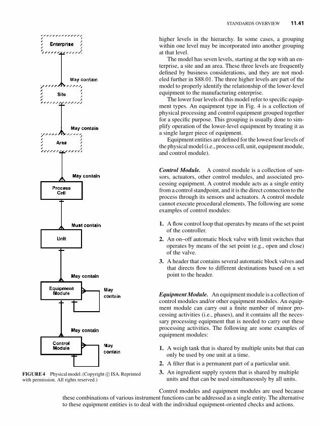
1.8P1: xxx
31 August 1999 21:52 chap11.tex CHAP-11.SGM MH009v3(1999/07/12)
STANDARDS OVERVIEW 11.41
FIGURE 4 Physical model. (Copyright c© ISA. Reprintedwith permission. All rights reserved.)
higher levels in the hierarchy. In some cases, a groupingwithin one level may be incorporated into another groupingat that level.
The model has seven levels, starting at the top with an en-terprise, a site and an area. These three levels are frequentlydefined by business considerations, and they are not mod-eled further in S88.01. The three higher levels are part of themodel to properly identify the relationship of the lower-levelequipment to the manufacturing enterprise.
The lower four levels of this model refer to specific equip-ment types. An equipment type in Fig. 4 is a collection ofphysical processing and control equipment grouped togetherfor a specific purpose. This grouping is usually done to sim-plify operation of the lower-level equipment by treating it asa single larger piece of equipment.
Equipment entities are defined for the lowest four levels ofthe physical model (i.e., process cell, unit, equipment module,and control module).
Control Module. A control module is a collection of sen-sors, actuators, other control modules, and associated pro-cessing equipment. A control module acts as a single entityfrom a control standpoint, and it is the direct connection to theprocess through its sensors and actuators. A control modulecannot execute procedural elements. The following are someexamples of control modules:
1. A flow control loop that operates by means of the set pointof the controller.
2. An on–off automatic block valve with limit switches thatoperates by means of the set point (e.g., open and close)of the valve.
3. A header that contains several automatic block valves andthat directs flow to different destinations based on a setpoint to the header.
Equipment Module. An equipment module is a collection ofcontrol modules and/or other equipment modules. An equip-ment module can carry out a finite number of minor pro-cessing activities (i.e., phases), and it contains all the neces-sary processing equipment that is needed to carry out theseprocessing activities. The following are some examples ofequipment modules:
1. A weigh tank that is shared by multiple units but that canonly be used by one unit at a time.
2. A filter that is a permanent part of a particular unit.
3. An ingredient supply system that is shared by multipleunits and that can be used simultaneously by all units.
Control modules and equipment modules are used becausethese combinations of various instrument functions can be addressed as a single entity. The alternativeto these equipment entities is to deal with the individual equipment-oriented checks and actions.
1.8P1: xxx
31 August 1999 21:52 chap11.tex CHAP-11.SGM MH009v3(1999/07/12)
11.42 PROCESS/INDUSTRIAL INSTRUMENTS AND CONTROLS HANDBOOK
Unit. A unit is usually centered on a major piece of process equipment, and it frequently operateson or contains the complete batch. Although a unit may operate on or contain only a portion of abatch, it cannot operate on or contain more than one batch at a time.
Units are the primary object for automatic control, and they have a direct relationship with unitprocedures and operations. A unit is made up of control modules and/or equipment modules, and therewill often be multiple units involved in making a batch. Control modules and equipment modulescan exist as:
� permanently included parts of a unit� temporarily attached parts of a unit� totally separate from a unit
When control modules and/or equipment modules are not part of a unit, they may be connected to aunit, and then they may be commanded like any other object in the unit.
Process Cell. A process cell is a logical grouping of equipment that is required for the productionof one or more batches. A process cell may contain more than one grouping of equipment that isneeded to make a batch. That grouping is referred to as a Train. The equipment that was actually usedto execute a batch is referred to as the Path. A process cell frequently contains more than one batchat a time.
Partitioning Equipment Entities
This section discusses the general principles involved in partitioning a process cell into equipmententities that can carry out specified processing activities or equipment-specific actions [4], [5].
The physical process cell design can greatly influence the implementation of batch control. Minordifferences in the physical system can dramatically affect the organization of equipment entities andprocedural elements.
All control-related sections of the standard assume that the process cell in question (both physicalequipment and related control activities) has been subdivided into well-defined equipment entitiessuch as units, equipment modules, and control modules. Effective subdivision of the process cell intowell-defined equipment entities is a complex activity, and it is highly dependent on the individualrequirements of the specific environment in which the batch process exists. Inconsistent or inappro-priate equipment subdivisions can compromise the effectiveness of the modular approach to recipessuggested by this standard, and they may result in a solution that:
� is difficult to support and enhance� fails to exploit the inherent flexibility of the plant� requires control system experts to assist process personnel when they are developing new recipes
or modifying existing recipes
Subdivision of the process cell requires a clear understanding of the purpose of the process cell’sequipment. Such understanding allows the identification of equipment entities that can work togetherto serve an identifiable processing purpose.
Process Cells. The subdivision of a process cell usually follows the principles listed below:
1. The function any equipment entity serves in product processing must be clear and unambiguous.
2. The function performed by the equipment entity must be consistent in terms of processing task,and it should be usable for that task no matter what product is being manufactured at a given time.
3. Subordinate equipment entities should be able to execute their task(s) independently and asyn-chronously because this allows the highest level equipment entity to orchestrate the activities ofits subordinates.
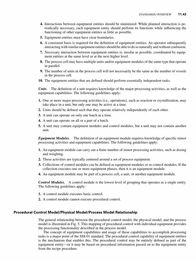
1.8P1: xxx
31 August 1999 21:52 chap11.tex CHAP-11.SGM MH009v3(1999/07/12)
STANDARDS OVERVIEW 11.43
4. Interactions between equipment entities should be minimized. While planned interaction is pe-riodically necessary, each equipment entity should perform its functions while influencing thefunctioning of other equipment entities as little as possible.
5. Equipment entities must have clear boundaries.
6. A consistent basis is required for the definition of equipment entities. An operator subsequentlyinteracting with similar equipment entities should be able to do so naturally and without confusion.
7. Necessary interaction between equipment entities is, insofar as possible, coordinated by equip-ment entities at the same level or at the next higher level.
8. The process cell may have multiple units and/or equipment modules of the same type that operatein parallel.
9. The number of units in the process cell will not necessarily be the same as the number of vesselsin the process cell.
10. The equipment entities that are defined should perform essentially independent tasks.
Units. The definition of a unit requires knowledge of the major processing activities, as well as theequipment capabilities. The following guidelines apply:
1. One or more major processing activities (i.e., operations), such as reaction or crystallization, maytake place in a unit, but only one may be active at a time.
2. Units should be defined such that they operate relatively independently of each other.
3. A unit can operate on only one batch at a time.
4. A unit can operate on all or a part of a batch.
5. A unit may contain equipment modules and control modules, but a unit may not contain anotherunit.
Equipment Modules. The definition of an equipment module requires knowledge of specific minorprocessing activities and equipment capabilities. The following guidelines apply:
1. An equipment module can carry out a finite number of minor processing activities, such as dosingand weighing.
2. These activities are typically centered around a set of process equipment.
3. Collections of control modules can be defined as equipment modules or as control modules. If thecollection executes one or more equipment phases, then it is an equipment module.
4. An equipment module may be part of a process cell, a unit, or another equipment module.
Control Modules. A control module is the lowest level of grouping that operates as a single entity.The following guidelines apply:
1. A control module executes basic control.
2. A control module cannot execute procedural control.
Procedural Control Model/Physical Model/Process Model Relationship
The general relationship between the procedural control model, the physical model, and the processmodel is illustrated in Fig. 5. This mapping of procedural control with individual equipment providesthe processing functionality described in the process model.
The concept of equipment capabilities and usage of these capabilities to accomplish processingtasks is a major point of the S88.01 standard. The procedural control capability of equipment entitiesis the mechanism that enables this. The procedural control may be entirely defined as part of theequipment entity—or it may be based on procedural information passed on to the equipment entityfrom the recipe procedure.
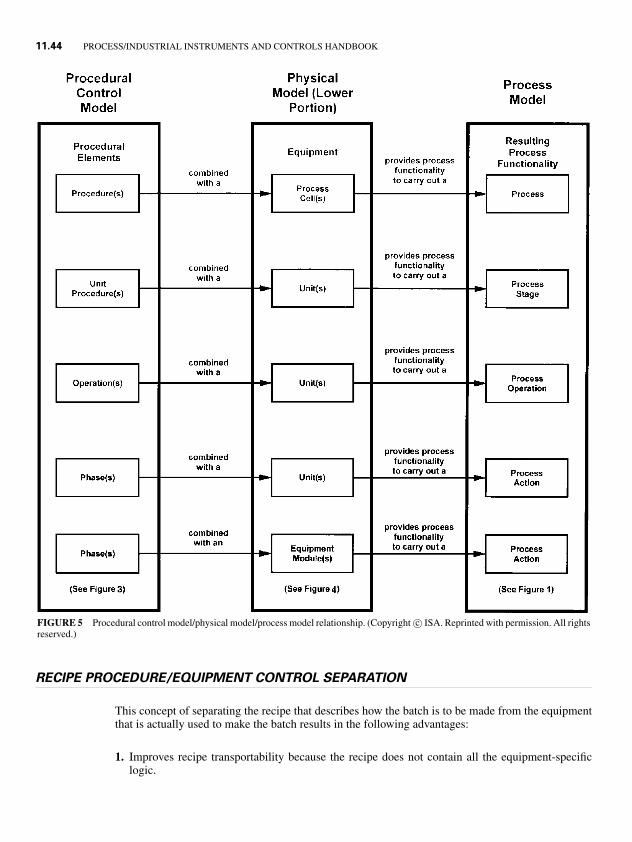
1.8P1: xxx
31 August 1999 21:52 chap11.tex CHAP-11.SGM MH009v3(1999/07/12)
11.44 PROCESS/INDUSTRIAL INSTRUMENTS AND CONTROLS HANDBOOK
FIGURE 5 Procedural control model/physical model/process model relationship. (Copyright c© ISA. Reprinted with permission. All rightsreserved.)
RECIPE PROCEDURE/EQUIPMENT CONTROL SEPARATION
This concept of separating the recipe that describes how the batch is to be made from the equipmentthat is actually used to make the batch results in the following advantages:
1. Improves recipe transportability because the recipe does not contain all the equipment-specificlogic.
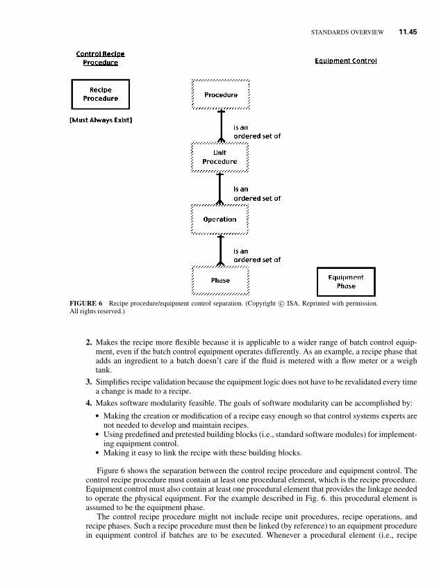
1.8P1: xxx
31 August 1999 21:52 chap11.tex CHAP-11.SGM MH009v3(1999/07/12)
STANDARDS OVERVIEW 11.45
FIGURE 6 Recipe procedure/equipment control separation. (Copyright c© ISA. Reprinted with permission.All rights reserved.)
2. Makes the recipe more flexible because it is applicable to a wider range of batch control equip-ment, even if the batch control equipment operates differently. As an example, a recipe phase thatadds an ingredient to a batch doesn’t care if the fluid is metered with a flow meter or a weightank.
3. Simplifies recipe validation because the equipment logic does not have to be revalidated every timea change is made to a recipe.
4. Makes software modularity feasible. The goals of software modularity can be accomplished by:� Making the creation or modification of a recipe easy enough so that control systems experts are
not needed to develop and maintain recipes.� Using predefined and pretested building blocks (i.e., standard software modules) for implement-
ing equipment control.� Making it easy to link the recipe with these building blocks.
Figure 6 shows the separation between the control recipe procedure and equipment control. Thecontrol recipe procedure must contain at least one procedural element, which is the recipe procedure.Equipment control must also contain at least one procedural element that provides the linkage neededto operate the physical equipment. For the example described in Fig. 6. this procedural element isassumed to be the equipment phase.
The control recipe procedure might not include recipe unit procedures, recipe operations, andrecipe phases. Such a recipe procedure must then be linked (by reference) to an equipment procedurein equipment control if batches are to be executed. Whenever a procedural element (i.e., recipe
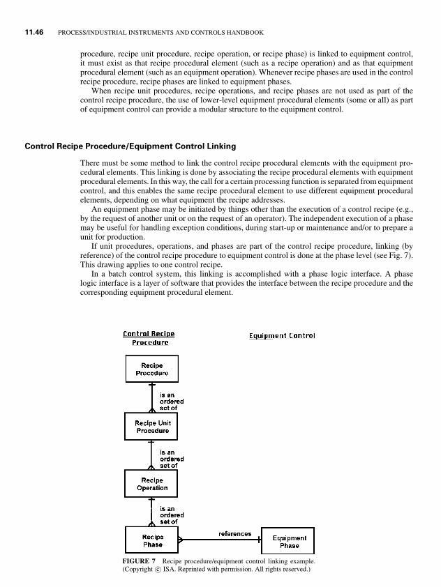
1.8P1: xxx
31 August 1999 21:52 chap11.tex CHAP-11.SGM MH009v3(1999/07/12)
11.46 PROCESS/INDUSTRIAL INSTRUMENTS AND CONTROLS HANDBOOK
procedure, recipe unit procedure, recipe operation, or recipe phase) is linked to equipment control,it must exist as that recipe procedural element (such as a recipe operation) and as that equipmentprocedural element (such as an equipment operation). Whenever recipe phases are used in the controlrecipe procedure, recipe phases are linked to equipment phases.
When recipe unit procedures, recipe operations, and recipe phases are not used as part of thecontrol recipe procedure, the use of lower-level equipment procedural elements (some or all) as partof equipment control can provide a modular structure to the equipment control.
Control Recipe Procedure/Equipment Control Linking
There must be some method to link the control recipe procedural elements with the equipment pro-cedural elements. This linking is done by associating the recipe procedural elements with equipmentprocedural elements. In this way, the call for a certain processing function is separated from equipmentcontrol, and this enables the same recipe procedural element to use different equipment proceduralelements, depending on what equipment the recipe addresses.
An equipment phase may be initiated by things other than the execution of a control recipe (e.g.,by the request of another unit or on the request of an operator). The independent execution of a phasemay be useful for handling exception conditions, during start-up or maintenance and/or to prepare aunit for production.
If unit procedures, operations, and phases are part of the control recipe procedure, linking (byreference) of the control recipe procedure to equipment control is done at the phase level (see Fig. 7).This drawing applies to one control recipe.
In a batch control system, this linking is accomplished with a phase logic interface. A phaselogic interface is a layer of software that provides the interface between the recipe procedure and thecorresponding equipment procedural element.
FIGURE 7 Recipe procedure/equipment control linking example.(Copyright c© ISA. Reprinted with permission. All rights reserved.)
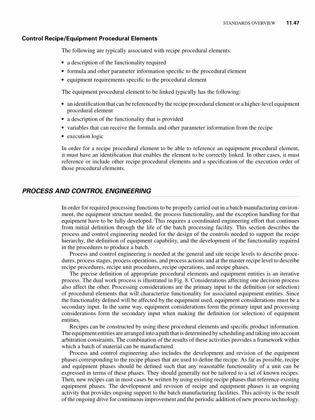
1.8P1: xxx
31 August 1999 21:52 chap11.tex CHAP-11.SGM MH009v3(1999/07/12)
STANDARDS OVERVIEW 11.47
Control Recipe/Equipment Procedural Elements
The following are typically associated with recipe procedural elements:
� a description of the functionality required� formula and other parameter information specific to the procedural element� equipment requirements specific to the procedural element
The equipment procedural element to be linked typically has the following:
� an identification that can be referenced by the recipe procedural element or a higher-level equipmentprocedural element
� a description of the functionality that is provided� variables that can receive the formula and other parameter information from the recipe� execution logic
In order for a recipe procedural element to be able to reference an equipment procedural element,it must have an identification that enables the element to be correctly linked. In other cases, it mustreference or include other recipe procedural elements and a specification of the execution order ofthose procedural elements.
PROCESS AND CONTROL ENGINEERING
In order for required processing functions to be properly carried out in a batch manufacturing environ-ment, the equipment structure needed, the process functionality, and the exception handling for thatequipment have to be fully developed. This requires a coordinated engineering effort that continuesfrom initial definition through the life of the batch processing facility. This section describes theprocess and control engineering needed for the design of the controls needed to support the recipehierarchy, the definition of equipment capability, and the development of the functionality requiredin the procedures to produce a batch.
Process and control engineering is needed at the general and site recipe levels to describe proce-dures, process stages, process operations, and process actions and at the master recipe level to describerecipe procedures, recipe unit procedures, recipe operations, and recipe phases.
The precise definition of appropriate procedural elements and equipment entities is an iterativeprocess. The dual work process is illustrated in Fig. 8. Considerations affecting one decision processalso affect the other. Processing considerations are the primary input to the definition (or selection)of procedural elements that will characterize functionality for associated equipment entities. Sincethe functionality defined will be affected by the equipment used, equipment considerations must be asecondary input. In the same way, equipment considerations form the primary input and processingconsiderations form the secondary input when making the definition (or selection) of equipmententities.
Recipes can be constructed by using these procedural elements and specific product information.The equipment entities are arranged into a path that is determined by scheduling and taking into accountarbitration constraints. The combination of the results of these activities provides a framework withinwhich a batch of material can be manufactured.
Process and control engineering also includes the development and revision of the equipmentphases corresponding to the recipe phases that are used to define the recipe. As far as possible, recipeand equipment phases should be defined such that any reasonable functionality of a unit can beexpressed in terms of these phases. They should generally not be tailored to a set of known recipes.Then, new recipes can in most cases be written by using existing recipe phases that reference existingequipment phases. The development and revision of recipe and equipment phases is an ongoingactivity that provides ongoing support to the batch manufacturing facilities. This activity is the resultof the ongoing drive for continuous improvement and the periodic addition of new process technology.
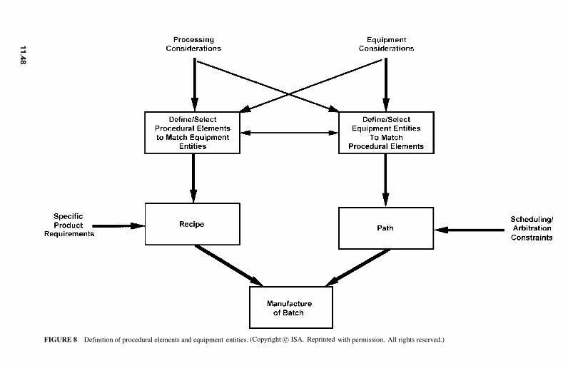
1.8P1:xxx
31A
ugust199921:52
chap11.texC
HA
P-11.SGM
MH
009v3(1999/07/12)
FIGURE 8 Definition of procedural elements and equipment entities. (Copyright c© ISA. Reprinted with permission. All rights reserved.)
11
.48

1.8P1: xxx
31 August 1999 21:52 chap11.tex CHAP-11.SGM MH009v3(1999/07/12)
STANDARDS OVERVIEW 11.49
CONTROL SYSTEM FUNCTIONAL SPECIFICATIONS
The models and terminology that are defined in S88.01 can be used as the basis for developingvendor-neutral or vendor-specific functional specifications for batch control. By the application ofobject-oriented techniques, reusable modules can be developed that can then be used from project toproject.
What Is Needed To Define Batch Control
The following is the information that is needed in order to define the batch control requirements fora particular project:
� how the product is to be made (i.e., recipes)� what equipment is to be controlled (i.e., equipment entities)� what control is needed (i.e., control activities and control functions)
Recipes and equipment entities were discussed in previous sections. Control activities and controlfunctions are defined by the control activity model (see Fig. 9). This model provides the basis fordefining the control functionality that is required.
The control activity model is the cornerstone of the S88.01 standard. These control activities arethe ones that are necessary to manage and control production in a batch manufacturing plant. The
FIGURE 9 Control activity model. (Copyright c© ISA. Reprinted with permission. All rightsreserved.)
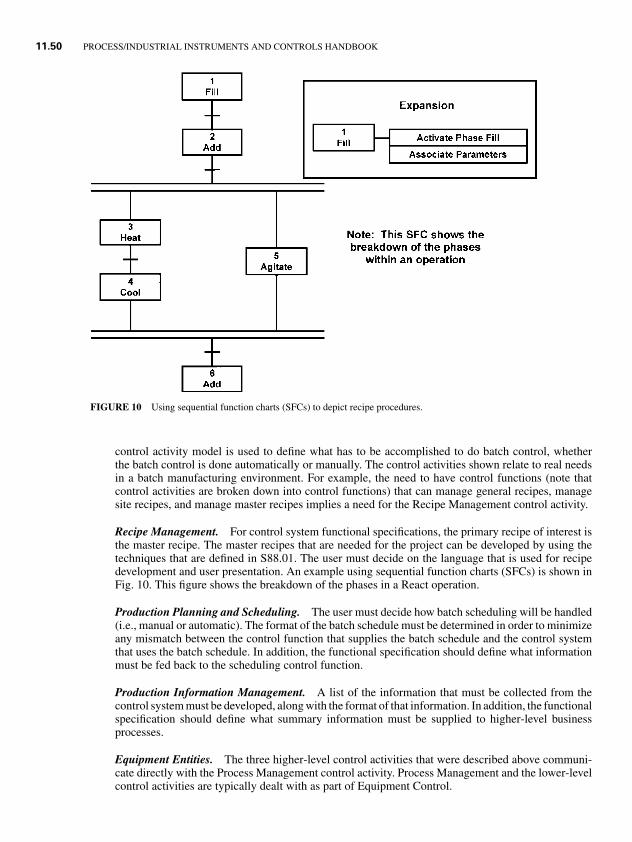
1.8P1: xxx
31 August 1999 21:52 chap11.tex CHAP-11.SGM MH009v3(1999/07/12)
11.50 PROCESS/INDUSTRIAL INSTRUMENTS AND CONTROLS HANDBOOK
FIGURE 10 Using sequential function charts (SFCs) to depict recipe procedures.
control activity model is used to define what has to be accomplished to do batch control, whetherthe batch control is done automatically or manually. The control activities shown relate to real needsin a batch manufacturing environment. For example, the need to have control functions (note thatcontrol activities are broken down into control functions) that can manage general recipes, managesite recipes, and manage master recipes implies a need for the Recipe Management control activity.
Recipe Management. For control system functional specifications, the primary recipe of interest isthe master recipe. The master recipes that are needed for the project can be developed by using thetechniques that are defined in S88.01. The user must decide on the language that is used for recipedevelopment and user presentation. An example using sequential function charts (SFCs) is shown inFig. 10. This figure shows the breakdown of the phases in a React operation.
Production Planning and Scheduling. The user must decide how batch scheduling will be handled(i.e., manual or automatic). The format of the batch schedule must be determined in order to minimizeany mismatch between the control function that supplies the batch schedule and the control systemthat uses the batch schedule. In addition, the functional specification should define what informationmust be fed back to the scheduling control function.
Production Information Management. A list of the information that must be collected from thecontrol system must be developed, along with the format of that information. In addition, the functionalspecification should define what summary information must be supplied to higher-level businessprocesses.
Equipment Entities. The three higher-level control activities that were described above communi-cate directly with the Process Management control activity. Process Management and the lower-levelcontrol activities are typically dealt with as part of Equipment Control.
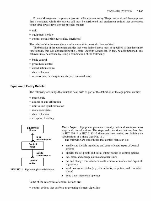
1.8P1: xxx
31 August 1999 21:52 chap11.tex CHAP-11.SGM MH009v3(1999/07/12)
STANDARDS OVERVIEW 11.51
Process Management maps to the process cell equipment entity. The process cell and the equipmentthat is contained within the process cell must be partitioned into equipment entities that correspondto the three lowest levels of the physical model:
� unit� equipment module� control module (includes safety interlocks)
The relationships between these equipment entities must also be specified.The behavior of the equipment entities that were defined above must be specified so that the control
functionality that was defined using the Control Activity Model can, in fact, be accomplished. Thisbehavior may be defined by using a combination of the following:
� basic control� procedural control� coordination control� data collection� operator interface requirements (not discussed here)
Equipment Entity Details
The following are things that must be dealt with as part of the definition of the equipment entities:
� phase logic� allocation and arbitration� unit-to-unit synchronization� modes and states� data collection� exception handling
FIGURE 11 Equipment phase subdivisions.
Phase Logic. Equipment phases are usually broken down into controlsteps and control actions. The steps and transitions that are describedin IEC 60848 or IEC 61131-3 document one method for defining thesubdivisions of a phase (see Fig. 11).
The following are some things that control steps can do:
• enable and disable regulating and state-oriented types of controlactions
• specify the set points and initial output values of control actions
• set, clear, and change alarms and other limits
• set and change controller constants, controller modes, and types ofalgorithms
• read process variables (e.g., alarm limits, set points, and controllerstatus)
• send a message to an operator
Some of the categories of control actions are:
� control actions that perform an actuating element algorithm
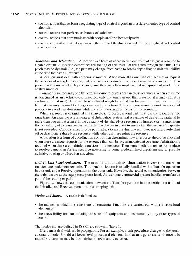
1.8P1: xxx
31 August 1999 21:52 chap11.tex CHAP-11.SGM MH009v3(1999/07/12)
11.52 PROCESS/INDUSTRIAL INSTRUMENTS AND CONTROLS HANDBOOK
� control actions that perform a regulating type of control algorithm or a state-oriented type of controlalgorithm
� control actions that perform arithmetic calculations� control actions that communicate with people and/or other equipment� control actions that make decisions and then control the direction and timing of higher-level control
components
Allocation and Arbitration. Allocation is a form of coordination control that assigns a resource toa batch or unit. Allocation determines the routing or the “path” of the batch through the units. Thispatch may be dynamic (i.e., the path may change from batch to batch) depending on unit availabilityat the time the batch is executed.
Allocation must deal with common resources. When more than one unit can acquire or requestthe services of a single resource, that resource is a common resource. Common resources are oftenpresent with complex batch processes, and they are often implemented as equipment modules orcontrol modules.
Common resources may be either exclusive-use resources or shared-use resources. When a resourceis designated as an exclusive-use resource, only one unit can use that resource at a time (i.e., it isexclusive to that unit). An example is a shared weigh tank that can be used by many reactor unitsbut that can only be used to charge one reactor at a time. This common resource must be allocatedproperly to avoid unit downtime while the unit is waiting for the use of the resource.
When a resource is designated as a shared-use resource, several units may use the resource at thesame time. An example is a raw-material distribution system that is capable of delivering material tomore than one unit at a time. If the capacity of the shared-use resource is limited (e.g., a maximumflow capability of a steam header), controls must be put in place to ensure that the resource’s capacityis not exceeded. Controls must also be put in place to ensure that one unit does not improperly shutoff or deactivate a shared-use resource while other units are using the resource.
Arbitration is a form of coordination control that determines how a resource should be allocatedwhen there are more requests for the resource than can be accommodated at one time. Arbitration isrequired when there are multiple requestors for a resource. Then some method must be put in placeto resolve contention for the resource according to some predetermined algorithm and to providedefinitive routing or allocation direction.
Unit-To-Unit Synchronization. The need for unit-to-unit synchronization is very common whentransfers are made between units. This synchronization is usually handled with a Transfer operationin one unit and a Receive operation in the other unit. However, the actual communication betweenthe units occurs at the equipment phase level. At least one commercial system handles transfers aspart of the routing or path.
Figure 12 shows the communication between the Transfer operation in an esterification unit andthe Initialize and Receive operations in a stripping unit.
Modes and States. A mode is defined as:
� the manner in which the transitions of sequential functions are carried out within a proceduralelement or
� the accessibility for manipulating the states of equipment entities manually or by other types ofcontrol
The modes that are defined in S88.01 are shown in Table 1.Users must deal with mode propagation. For an example, a unit procedure changes to the semi-
automatic mode. Should all lower-level procedural elements in that unit go to the semi-automaticmode? Propagation may be from higher to lower and vice versa.
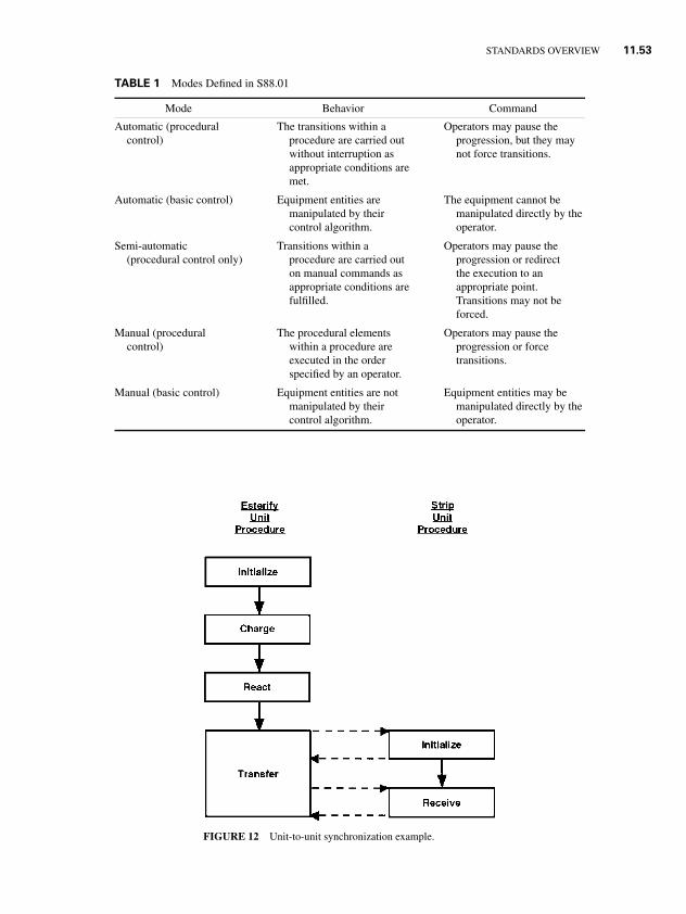
1.8P1: xxx
31 August 1999 21:52 chap11.tex CHAP-11.SGM MH009v3(1999/07/12)
STANDARDS OVERVIEW 11.53
TABLE 1 Modes Defined in S88.01
Mode Behavior Command
Automatic (procedural The transitions within a Operators may pause thecontrol) procedure are carried out progression, but they may
without interruption as not force transitions.appropriate conditions aremet.
Automatic (basic control) Equipment entities are The equipment cannot bemanipulated by their manipulated directly by thecontrol algorithm. operator.
Semi-automatic Transitions within a Operators may pause the(procedural control only) procedure are carried out progression or redirect
on manual commands as the execution to anappropriate conditions are appropriate point.fulfilled. Transitions may not be
forced.
Manual (procedural The procedural elements Operators may pause thecontrol) within a procedure are progression or force
executed in the order transitions.specified by an operator.
Manual (basic control) Equipment entities are not Equipment entities may bemanipulated by their manipulated directly by thecontrol algorithm. operator.
FIGURE 12 Unit-to-unit synchronization example.
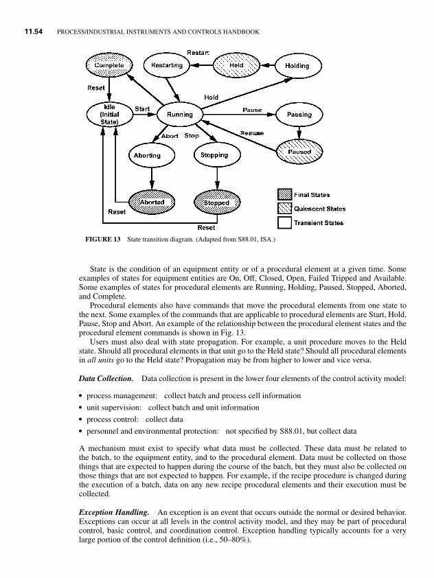
1.8P1: xxx
31 August 1999 21:52 chap11.tex CHAP-11.SGM MH009v3(1999/07/12)
11.54 PROCESS/INDUSTRIAL INSTRUMENTS AND CONTROLS HANDBOOK
FIGURE 13 State transition diagram. (Adapted from S88.01, ISA.)
State is the condition of an equipment entity or of a procedural element at a given time. Someexamples of states for equipment entities are On, Off, Closed, Open, Failed Tripped and Available.Some examples of states for procedural elements are Running, Holding, Paused, Stopped, Aborted,and Complete.
Procedural elements also have commands that move the procedural elements from one state tothe next. Some examples of the commands that are applicable to procedural elements are Start, Hold,Pause, Stop and Abort. An example of the relationship between the procedural element states and theprocedural element commands is shown in Fig. 13.
Users must also deal with state propagation. For example, a unit procedure moves to the Heldstate. Should all procedural elements in that unit go to the Held state? Should all procedural elementsin all units go to the Held state? Propagation may be from higher to lower and vice versa.
Data Collection. Data collection is present in the lower four elements of the control activity model:
� process management: collect batch and process cell information� unit supervision: collect batch and unit information� process control: collect data� personnel and environmental protection: not specified by S88.01, but collect data
A mechanism must exist to specify what data must be collected. These data must be related tothe batch, to the equipment entity, and to the procedural element. Data must be collected on thosethings that are expected to happen during the course of the batch, but they must also be collected onthose things that are not expected to happen. For example, if the recipe procedure is changed duringthe execution of a batch, data on any new recipe procedural elements and their execution must becollected.
Exception Handling. An exception is an event that occurs outside the normal or desired behavior.Exceptions can occur at all levels in the control activity model, and they may be part of proceduralcontrol, basic control, and coordination control. Exception handling typically accounts for a verylarge portion of the control definition (i.e., 50–80%).
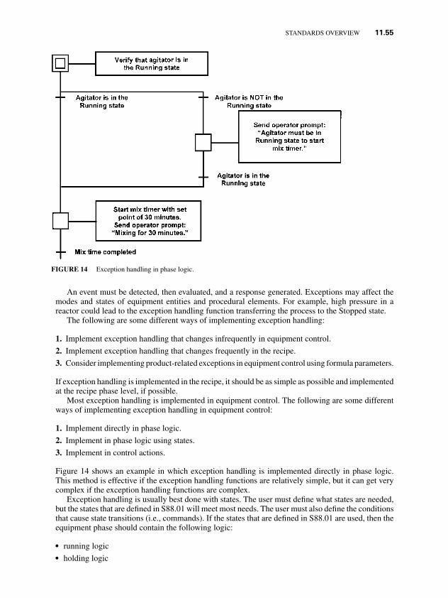
1.8P1: xxx
31 August 1999 21:52 chap11.tex CHAP-11.SGM MH009v3(1999/07/12)
STANDARDS OVERVIEW 11.55
FIGURE 14 Exception handling in phase logic.
An event must be detected, then evaluated, and a response generated. Exceptions may affect themodes and states of equipment entities and procedural elements. For example, high pressure in areactor could lead to the exception handling function transferring the process to the Stopped state.
The following are some different ways of implementing exception handling:
1. Implement exception handling that changes infrequently in equipment control.
2. Implement exception handling that changes frequently in the recipe.
3. Consider implementing product-related exceptions in equipment control using formula parameters.
If exception handling is implemented in the recipe, it should be as simple as possible and implementedat the recipe phase level, if possible.
Most exception handling is implemented in equipment control. The following are some differentways of implementing exception handling in equipment control:
1. Implement directly in phase logic.
2. Implement in phase logic using states.
3. Implement in control actions.
Figure 14 shows an example in which exception handling is implemented directly in phase logic.This method is effective if the exception handling functions are relatively simple, but it can get verycomplex if the exception handling functions are complex.
Exception handling is usually best done with states. The user must define what states are needed,but the states that are defined in S88.01 will meet most needs. The user must also define the conditionsthat cause state transitions (i.e., commands). If the states that are defined in S88.01 are used, then theequipment phase should contain the following logic:
� running logic� holding logic
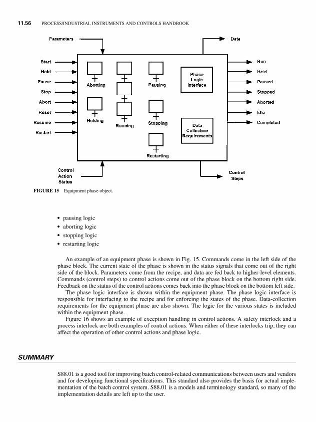
1.8P1: xxx
31 August 1999 21:52 chap11.tex CHAP-11.SGM MH009v3(1999/07/12)
11.56 PROCESS/INDUSTRIAL INSTRUMENTS AND CONTROLS HANDBOOK
FIGURE 15 Equipment phase object.
� pausing logic� aborting logic� stopping logic� restarting logic
An example of an equipment phase is shown in Fig. 15. Commands come in the left side of thephase block. The current state of the phase is shown in the status signals that come out of the rightside of the block. Parameters come from the recipe, and data are fed back to higher-level elements.Commands (control steps) to control actions come out of the phase block on the bottom right side.Feedback on the status of the control actions comes back into the phase block on the bottom left side.
The phase logic interface is shown within the equipment phase. The phase logic interface isresponsible for interfacing to the recipe and for enforcing the states of the phase. Data-collectionrequirements for the equipment phase are also shown. The logic for the various states is includedwithin the equipment phase.
Figure 16 shows an example of exception handling in control actions. A safety interlock and aprocess interlock are both examples of control actions. When either of these interlocks trip, they canaffect the operation of other control actions and phase logic.
SUMMARY
S88.01 is a good tool for improving batch control-related communications between users and vendorsand for developing functional specifications. This standard also provides the basis for actual imple-mentation of the batch control system. S88.01 is a models and terminology standard, so many of theimplementation details are left up to the user.
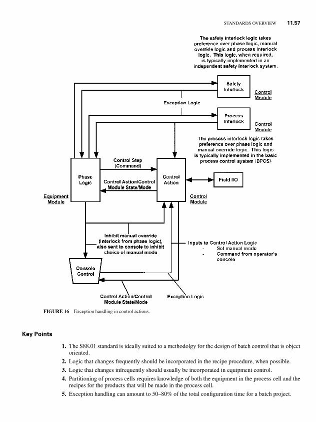
1.8P1: xxx
31 August 1999 21:52 chap11.tex CHAP-11.SGM MH009v3(1999/07/12)
STANDARDS OVERVIEW 11.57
FIGURE 16 Exception handling in control actions.
Key Points
1. The S88.01 standard is ideally suited to a methodolgy for the design of batch control that is objectoriented.
2. Logic that changes frequently should be incorporated in the recipe procedure, when possible.
3. Logic that changes infrequently should usually be incorporated in equipment control.
4. Partitioning of process cells requires knowledge of both the equipment in the process cell and therecipes for the products that will be made in the process cell.
5. Exception handling can amount to 50–80% of the total configuration time for a batch project.
1.8P1: xxx
31 August 1999 21:52 chap11.tex CHAP-11.SGM MH009v3(1999/07/12)
11.58 PROCESS/INDUSTRIAL INSTRUMENTS AND CONTROLS HANDBOOK
6. Reusable software components provide a lot of advantages in a batch control system.
7. Data collection is part of each equipment entity.
Rules of Thumb [6]
1. Understand the process before designing a batch control system for that process.
2. Design the control system before beginning implementation of the control system.
3. Get the end users involved in the design.
4. Exception handling is usually best done in equipment control.
5. The use of states simplifies dealing with exception handling in equipment control.
REFERENCES
1. ANSI/ISA-S88.01-1995, Batch Control—Part 1: Models and Terminology, 1995.
2. IEC61512:1997, Batch Control—Part 1: Models and Terminology, 1997.
3. NAMUR NE-33, Requirements To Be Met By Systems for Recipe-Based Operations, May 19, 1992.
4. Hopkinson, P., and J. Hancock, “A Case History of the Implementation of An S88-Aware Batch ControlSystem,” World Batch Forum, 1998.
5. Fleming, D. W., and P. E. Schreiber, “Batch Processing Design Example,” World Batch Forum, 1998.
6. Christie, D. A., “A Methodology for Batch Control Implementation—Real World Lessons,” World Batch Forum,1998.