section 2 12pt -...
TRANSCRIPT

Loads7
Section 2The New York City Seismic Code
2.1 Introduction
LOCAL LAW 17/95
To amend the administrative code of the city of New York, in relation to the design and construction of buildings,structures and portions thereof to resist the effects of earthquakes.
Be it enacted by the Council as follows:
Section 1. Article 5 of subchapter 9 of chapter 1 of title 27 of the administrative code of the city of New York isamended to read as follows:
ARTICLE 5
WIND LOADS AND EARTHQUAKE LOADS
27-569 Wind loads and earthquake loads. (a) WIND LOADS. - The structural frame and exteriorcomponents of all buildings, signs, tanks, and other exposed constructions shall be designed toresist the pressures due to wind as prescribed in reference standard RS 9-5. Wind shall be assumedto act from any direction. For continuous framing, the effects of partial loading conditions shall beconsidered.
(b) EARTHQUAKE LOADS. - Every building, structure and portion thereof shall, at a minimum,be designed and constructed to resist the effects of seismic ground motions as prescribed inreference standard RS 9-6.
Section 2. The listing for "Unreinforced Masonry" under the column entitled "Operations on StructuralElements That Shall Be Subject to Controlled Inspection" of table 10-2 of subdivision (c) of section 27-588 of theadministrative code of the city of New York is amended to read as follows:
Placement and bedding of units and sizes of members including thickness of walls and wythes;sizes of columns; cleanouts; and provisions for curing and protection against freezing for allmasonry construction proportioned on the basis of structural analysis as described in section fourof reference standard RS 10-1B, unless such operations are specifically not designated forcontrolled inspection.
Section 3. The listings for "Reinforced Masonry" and "Unreinforced Masonry" under the column entitled"Operations on Structural Elements That Are Not Subject to Controlled Inspection" of table 10-2 of subdivision (c)of section 27-588 of the administrative code of the city of New York are amended by repealing item (1) under both"Reinforced Masonry" and "Unreinforced Masonry" and, in each case, renumbering items (2), (3) and (4) to be (1),(2) and (3), respectively.
Section 4. The opening paragraph of section 27-594 of the administrative code of the city of New York isamended to read as follows:
Dead loads, live loads (including impact) and reduced live loads, where applicable, shall beconsidered as basic loads. Wind, earthquake, thermal forces, shrinkage, and unreduced live loads(where live load reduction is permitted by subchapter nine of this chapter) shall be considered asloads of infrequent occurrence. Members shall have adequate capacity to resist all applicable
Loads8
combinations of the loads listed in subchapter nine of this chapter, in accordance with thefollowing:
Section 5. Subdivision (a) of section 27-670 of the administrative code of the city of New York is amended toread as follows:
(a) Earth and ground water pressure. Every foundation wall or other wall serving as aretaining structure shall be designed to resist, in addition to the vertical loads acting thereon, theincident lateral earth pressures and surcharges, plus hydrostatic pressures corresponding to themaximum probable ground water level. Retaining walls shall be designed to resist at least thesuperimposed effects of the total static lateral soil pressure, excluding the pressure caused by anytemporary surcharge, plus an earthquake force of 0.045 wsh
2 (horizontal backfill surface), where
ws equals unit weight of soil and h equals wall height. Surcharges which are applied overextended periods of time shall be included in the total static lateral soil pressure and theirearthquake lateral force shall be computed and added to the force of 0.045 wsh
2. The earthquakeforce from backfill shall be distributed as an inverse triangle over the height of the wall. The pointof application of the earthquake force from an extended duration surcharge shall be determinedon an individual case basis. If the backfill consists of loose saturated granular soil, considerationshall be given to the potential liquefication of the backfill during the seismic loading usingreference standard RS 9-6.
Section 6. The list of referenced national standards of reference standard RS-9 of the appendix to chapter 1 oftitle 27 of the administrative code of the city of New York is amended by adding a new standard to read as follows:
2.2 Loads
UBC SECTION 2312Earthquake Regulations with Accumulative Supplement 1990
Section 7. Reference standard RS-9 of the appendix to chapter 1 of title 27 of such code is amended by adding anew reference standard RS 9-6 to read as follows:
The following text includes the amendments to the 1988 UBC within the text of the UBC provisions. Theseamendments are shown in italics.
REFERENCE STANDARD RS 9-6EARTHQUAKE LOADS
UBC SECTION 2312-1990 Earthquake Regulations with Accumulative Supplement
MODIFICATIONS - The provisions of UBC Section 2312 shall be subject to the following modifications. Thesubdivisions, paragraphs, subparagraphs and items are from this section.
Earthquake RegulationsSec. 2312 (a) General. 1. Minimum seismic design . The following types of construction shall, at a
minimum, be designed and constructed to resist the effects of seismic ground motions as provided in this section:- new structures on new foundations;- new structures on existing foundations; and- enlargements in and of themselves on new foundations.Buildings classified in New York City occupancy group J-3 and not more than three stories in height need not
conform to the provisions of this section.The Commissioner may require that the following types of construction be designed and constructed to
incorporate safety measures as necessary to provide safety against the effects of seismic ground motions at leastequivalent to that provided in a structure to which the provisions of this section are applicable:
Loads9
- new buildings classified in occupancy group J-3 and which are three stories or less in height; and- enlargements in and of themselves where the costs of such enlargement exceeds sixty percent of the value of the building.Pursuant to section 27-191 of the code the Commissioner shall have the authority to reject an application for a
building permit which fails to comply with the requirements of this section.2. Seismic and wind. When the code-prescribed wind design produces greater effects, the wind design shall
govern, but detailing requirements and limitations prescribed in this and referenced sections shall be followed.(b) Definitions. For the purposes of this section certain items are defined as follows:BASE is the level at which the earthquake motions are considered to be imparted to the structure or the level at
which the structure as a dynamic vibrator is supported.BASE SHEAR, V, is the total design lateral force or shear at the base of a structure.BEARING WALL SYSTEM is a structural system without a complete vertical load-carrying space frame. See
Section 2312 (d) 6 B.BOUNDARY ELEMENT is an element at edges of openings or at perimeters of shear walls or diaphragms.BRACED FRAME is an essentially vertical truss system of the concentric or eccentric type which is provided
to resist lateral forces.BUILDING FRAME SYSTEM is an essentially complete space frame which provides support for gravity
loads. See Section 2312 (d) 6 C.COLLECTOR is a member or element provided to transfer lateral forces from a portion of a structure to
vertical elements of the lateral force-resisting system.CONCENTRIC BRACED FRAME is a braced frame in which the members are subjected primarily to axial
forces.DIAPHRAGM is a horizontal or nearly horizontal system acting to transmit lateral forces to the vertical
resisting elements. The term "diaphragm" includes horizontal bracing systems.DIAPHRAGM CHORD is the boundary element of a diaphragm or shear wall which is assumed to take axial
stresses analogous to the flanges of a beam.DIAPHRAGM STRUT (drag strut, tie, collector) is the element of a diaphragm parallel to the applied load
which collects and transfers diaphragm shear to vertical resisting elements or distributes loads within the diaphragm.Such members may take axial tension or compression.
DRIFT see STORY DRIFT.DUAL SYSTEM is a combination of a special or intermediate moment-resisting space frame and shear walls or
braced frames designed in accordance with the criteria of Section 2312 (d) 6 E.ECCENTRIC BRACED FRAME (EBF) is a steel-braced frame designed in conformance with reference
standard RS 10-5C.ESSENTIAL FACILITIES are those structures which are necessary for emergency operations subsequent to a
natural disaster.FLEXIBLE ELEMENT or system is one whose deformation under lateral load is significantly larger than
adjoining parts of the system. Limiting ratios for defining specific flexible elements are set forth in Section 2312 (e)3 B (ii), 2312 (e) 6 or 2312 (g) 2.
HORIZONTAL BRACING SYSTEM is a horizontal truss system that serves the same function as adiaphragm.
INTERMEDIATE MOMENT-RESISTING FRAME (IMRF) is a concrete frame designed in accordance withthe requirements of Chapters 1 through 20 and Sections 21.1, 21.2 and 21.9 of reference standard RS 10-3.
LATERAL FORCE-RESISTING SYSTEM is that part of the structural system assigned to resist lateralforces.
MOMENT-RESISTING FRAME is a frame in which members and joints are capable of resisting forcesprimarily by flexure.
ORDINARY MOMENT-RESISTING FRAME (OMRF) is a moment-resisting frame conforming to therequirements of Chapters 1 through 20 of reference standard RS 10-3 or reference standards RS 10-5A and RS 10-5C but not meeting the special detailing requirements for ductile behavior.
ORTHOGONAL EFFECTS are the effects on structural elements common to the resisting systems along twoorthogonal axes due to earthquake forces acting in a direction other than those axes.
P-DELTA EFFECT is the secondary effect on shears, axial forces and moments of frame members induced bythe vertical loads acting on the laterally displaced building frame.
Loads10
REINFORCED MASONRY SHEAR WALL is that form of masonry wall construction in which reinforcementacting in conjunction with masonry is used to resist lateral forces parallel to the wall and which is designed usingreinforcement in conformance with Chapter 7 of reference standard RS 10-2.
SHEAR WALL is a wall designed to resist lateral forces parallel to the plane of the wall (sometimes referred toas a vertical diaphragm).
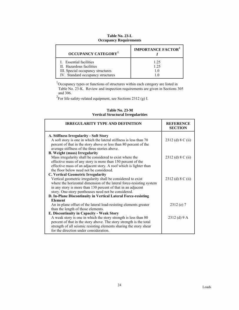
SOFT STORY is one in which the lateral stiffness is less than 70 percent of the stiffness of the story above. SeeTable No. 23-M.
SPECIAL MOMENT-RESISTING FRAME (SMRF) is a moment-resisting frame conforming to referencestandards RS 10-3 or RS 10-5A and RS 10-5C and specially detailed to provide ductile behavior by complying withthe requirements of Chapters 1 through 20 and Sections 21.1 through 21.8 of reference standard RS 10-3 orreference standards RS 10-5A and RS 10-5C.
STORY is the space between levels. Story x is the story below Level x.STORY DRIFT is the displacement of one level relative to the level above or below, including translational and
torsional deflections.STORY DRIFT RATIO is the story drift divided by the story height.STORY SHEAR, Vx, is the summation of design lateral forces above the story under consideration.STRENGTH is the useable capacity of a structure or its members to resist load within the deformation limits
prescribed in this section and referenced sections.STRUCTURE is an assemblage of framing members designed to support gravity loads and resist lateral forces.
Structures may be categorized as building structures or Non-building structures.VERTICAL LOAD-CARRYING FRAME is a frame designed to carry all vertical gravity loads.WEAK STORY is one in which the story strength is less than 80 percent of that of the story above. See Table
No. 23-M.(c) Symbols and Notations. The following symbols and notations apply to the provisions of this section:
Ac = The combined effective area, in square feet, of the shear walls in the first story of the structure.
Ae = The minimum cross-sectional shear area in any horizontal plane in the first story, in square feet, of a shear wall.
Ax = Delete this term.C = Numerical coefficient specified in Section 2312 (e) 2 A.Cp = Numerical coefficient specified in Section 2312 (g) and given in Table No. 23-P.
Ct = Numerical coefficient given in Section 2312 (e) 2 B.
De = The length, in feet, of a shear wall in the first story in the direction parallel to the applied forces.di = Horizontal displacement at Level i relative to the base due to applied lateral forces, f, for use in
Formula (12-5).fi = Lateral force at Level i for use in Formula (12-5).
Fi,Fn,Fx = Lateral force applied to Level i, n, or x, respectively.
Fp = Lateral forces on a part of the structure.Ft = That portion of the base shear, V, considered concentrated at the top of the structure in addition
to Fn.g = Acceleration due to gravity.
hi,hn,hx = Height in feet above the base to Level i, n, or x, respectively.I = Importance factor given in Table No. 23-L.
Level i = Level of the structure referred to by the subscript i. "i = 1" designates the first level above the base.
Level n = That level which is uppermost in the main portion of the structure.Level x = That level which is under design consideration. "x = 1" designates the first level above the base.
Rw = Numerical coefficient given in Tables Nos. 23-0 and 23-Q.S = Site coefficient for soil characteristics given in Table No. 23-J.T = Fundamental period of vibration, in seconds, of the structure in the direction under consideration.V = The total design lateral force or shear at the base.Vx = The design story shear in Story x.

Loads11
W = The total seismic dead load defined in Section 2312 (e) 1.wi, wx = That portion of W which is located at or is assigned to Level i or x, respectively.
wpx = The weight of the diaphragm and the elements tributary thereto at Level x, including applicable portions of other loads defined in Section 2312 (e) 1.
Wp = The weight of an element or component.Z = Seismic zone factor given in Table No. 23-1.
(d) Criteria Selection. 1. Basis for design. The procedures and limitations for the design of structures shall bedetermined considering site characteristics, occupancy, configuration, structural system and height in accordancewith this section. The minimum design seismic forces shall be those determined in accordance with the static lateralforce procedure of Section 2312 (e) except as modified by 2312 (f) 5 C.
2. Seismic zone. The seismic zone factor, Z, for buildings, structures and portions thereof in New York Cityshall be 0.15. The seismic zone factor is the effective zero period acceleration for S1 type rock.
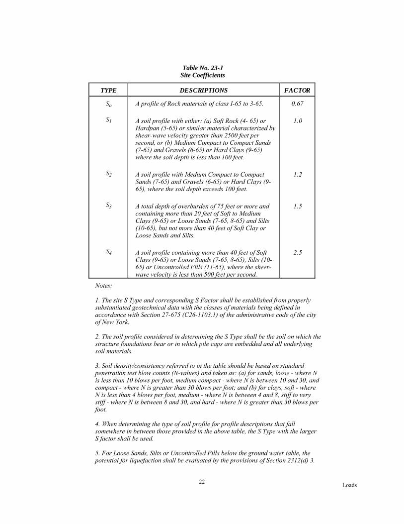
3. Site geology, soil characteristics and foundations. A. General. Soil profile type and site coefficient, S, shallbe established in accordance with Table No. 23-J.
B. Liquefaction.(i) Soils of classes 7-65, 8-65, 10-65 and non-cohesive class 11-65 below the ground water table and less than
fifty feet below the ground surface shall be considered to have potential for liquefaction,(ii) The potential for liquefaction of level ground shall be determined on the basis of Standard Penetration
Resistance (N) in accordance with Figure No. 4;Category A. Soil shall be considered liquefiable.Category B. Liquefaction is possible.Soil shall be considered liquefiable for structures of Occupancy Categories I, II and III of Table No. 23-K.Category C. Liquefaction is unlikely and need not be considered in design. At any site the highestcategory of liquefaction potential shall apply to the most critical strata or substrata.
(iii) Liquefiable soils shall be considered to have no passive (lateral) resistance or bearing capacity valueduring an earthquake. An analysis shall be submitted by an engineer, which demonstrates, subject to theapproval of the Commissioner, that the proposed construction is safe against liquefaction effects on thesoil.
(iv)Where liquefiable soils are present in sloped ground or over sloped nonliquefiable substrata and wherelateral displacement is possible, a stability analysis shall be submitted by an engineer, whichdemonstrates, subject to the approval of the Commissioner, that the proposed construction is safe againstfailure of the soil.
C. Foundation Plates and Sills. Foundation plates or sills shall be bolted to the foundation or foundation wallwith not less than one-half inch nominal diameter steel bolts embedded at least seven inches into the concrete ormasonry and spaced not more than six feet apart. There shall be a minimum of two bolts per piece with one boltlocated within twelve inches of each end of each piece. A properly sized nut and washer shall be tightened on eachbolt to the plate.
D. Foundation Interconnection of Pile Caps and Caissons. Individual pile caps and caissons of everystructure subjected to seismic forces shall be interconnected by ties. Such ties shall be capable of resisting, intension or compression, a minimum horizontal force equal to the product of ZI/4 and the larger column vertical loadat the end of each tie.
EXCEPTION: Other approved effective methods of foundation interconnection may be used where it can bedemonstrated by an analysis that equivalent restraint and relative displacement can be provided.
4. Occupancy categories. For purposes of earthquake-resistant design, each structure shall be placed in one ofthe occupancy categories listed in Table No. 23-K. Table No. 23-L lists importance factors, I, and reviewrequirements for each category.
5. Configuration requirements. A. General. Each structure shall be designated as being structurally regular orirregular.
B. Regular structures. Regular structures have no significant physical discontinuities in plan or verticalconfiguration or in their lateral force-resisting systems such as the irregular features described below.
C. Irregular structures.(i) Irregular structures have significant physical discontinuities in configuration or in their lateral force-
resisting systems. Irregular features include, but are not limited to, those described in Tables Nos. 23-Mand 23-N.
Loads12
(ii) Structures having one or more of the features listed in Table No. 23-M shall be designated as having avertical irregularity. EXCEPTION: Where no story drift ratio under design lateral forces is greater than 1.3 times the storydrift ratio of the story above the structure may be deemed to not have the structural irregularities of Type Aor Type B in Table No. 23-M. The story drift ratio for the top two stories need not be considered. The storydrifts for this determination may be calculated neglecting torsional effects.
(iii) Structures having one or more of the features listed in Table No. 23-N shall be designated as having a planirregularity.
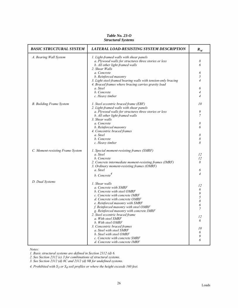
6. Structural systems. A. General. Structural systems shall be classified as one of the types listed in Table No.23-0 and defined in this subsection.
B. Bearing wall system. A structural system without a complete vertical load-carrying space frame. Bearingwalls or bracing systems provide support for all or most gravity loads. Resistance to lateral load is provided byshear walls or braced frames.
C. Building frame system. A structural system with an essentially complete space frame providing support forgravity loads. Resistance to lateral load is provided by shear walls or braced frames.
D. Moment-resisting frame system. A structural system with an essentially complete space frame providessupport for gravity loads. Moment-resisting space frames provide resistance to lateral load primarily by flexuralaction of members.
E. Dual system. A structural system with the following features:(i) An essentially complete space frame which provides support for gravity loads. (ii) Resistance to lateral load is provided by shear walls or braced frames and a moment-resisting frame
(SMRF, IMRF or OMRF). The moment-resisting frames shall be designed to independently resist at least25 percent of the design base shear. The shear walls or braced frames shall be designed to resist at least 75percent of the cumulative story shear at every level. Overturning effects may be distributed in accordancewith item (iii) below.
(iii) The two systems shall be designed to resist the total design base shear in proportion to their relativerigidities considering the interaction of the dual system at all levels.
F. Undefined structural system. A structural system not listed in Table No. 23-O.G. Non-building structural system. A structural system conforming to Section 2312 (i).7. Height limits. Delete paragraph.8. Selection of lateral force procedure. All structures shall be designed using either the static lateral force
procedure of Section 2312 (e) or using the dynamic lateral force procedure of Section 2312 (f). In addition, thedynamic lateral force procedure shall be considered, but is not required, for the design of the following:
A. Structures over 400 feet in height.B. Irregular structures.C. Structures located on Soil Profile Type S4 which have a period greater than 1 second. The analysis should
include the effects of soils at the site and should conform to Section 2312 (f) 2.9. System limitations. A. Discontinuity. Structures with a discontinuity in capacity, vertical irregularity Type
E as defined in Table No. 23-M, shall not be over two stories or 30 feet in height where the weak story has acalculated strength of less than 65 percent of the story above.
EXCEPTION: Where the weak story is capable of resisting a total lateral seismic force of 3 (Rw/8) timesthe design force prescribed in Section 2312 (e).
B. Undefined structural systems. Undefined structural systems shall be shown by technical and test datawhich establish the dynamic characteristics and demonstrate the lateral force resistance and energy absorptioncapacity to be equivalent to systems listed in Table No. 23-O for equivalent Rw values.
C. Irregular features. Only structures having either vertical irregularities Type D or E as defined in Table 23-M or horizontal irregularities Type D or E as defined in Table 23-N shall be designed to meet the additionalrequirements of those sections referenced in the tables.
10. Alternate procedures. Alternative lateral force procedures using rational analyses based on wellestablished principles of mechanics may be used in lieu of those prescribed when such procedures are consistentwith this standard and subject to the approval of the Commissioner.
(e) Minimum Design Lateral Forces and Related Effects. 1. General. Structures shall be designed forseismic forces coming from any horizontal direction.
Loads13
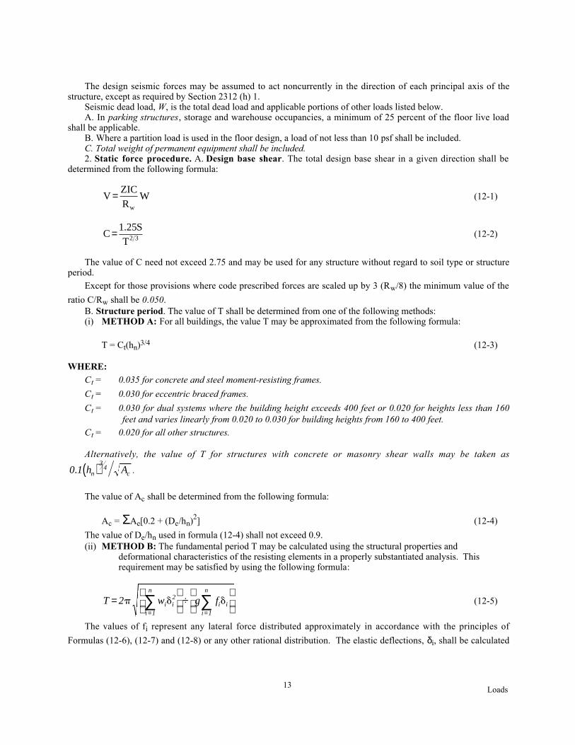
The design seismic forces may be assumed to act noncurrently in the direction of each principal axis of thestructure, except as required by Section 2312 (h) 1.
Seismic dead load, W, is the total dead load and applicable portions of other loads listed below.A. In parking structures, storage and warehouse occupancies, a minimum of 25 percent of the floor live load
shall be applicable.B. Where a partition load is used in the floor design, a load of not less than 10 psf shall be included.C. Total weight of permanent equipment shall be included.2. Static force procedure. A. Design base shear. The total design base shear in a given direction shall be
determined from the following formula:
VZICR
Ww
= (12-1)
CS
T= 1 25
2 3
.(12-2)
The value of C need not exceed 2.75 and may be used for any structure without regard to soil type or structureperiod.
Except for those provisions where code prescribed forces are scaled up by 3 (Rw/8) the minimum value of the
ratio C/Rw shall be 0.050.B. Structure period. The value of T shall be determined from one of the following methods:(i) METHOD A: For all buildings, the value T may be approximated from the following formula:
T = Ct(hn)3/4 (12-3)
WHERE:Ct = 0.035 for concrete and steel moment-resisting frames.
Ct = 0.030 for eccentric braced frames.
Ct = 0.030 for dual systems where the building height exceeds 400 feet or 0.020 for heights less than 160feet and varies linearly from 0.020 to 0.030 for building heights from 160 to 400 feet.
Ct = 0.020 for all other structures.
Alternatively, the value of T for structures with concrete or masonry shear walls may be taken as
0 1 h An
34
c. ( ) .
The value of Ac shall be determined from the following formula:
Ac = ΣAe[0.2 + (De/hn)2] (12-4)
The value of De/hn used in formula (12-4) shall not exceed 0.9.(ii) METHOD B: The fundamental period T may be calculated using the structural properties and
deformational characteristics of the resisting elements in a properly substantiated analysis. This requirement may be satisfied by using the following formula:
T 2 w g fi i2
i 1
n
i ii 1
n
=
÷
= =∑ ∑p d d (12-5)
The values of fi represent any lateral force distributed approximately in accordance with the principles of
Formulas (12-6), (12-7) and (12-8) or any other rational distribution. The elastic deflections, δi, shall be calculated

Loads14
using the applied lateral forces, fi. The value of C shall be not less than 80 percent of the value obtained by using Tfrom Method A.
3. Combinations of structural systems. A. General. Where combinations of structural systems areincorporated into the same structure, the requirements of this subsection shall be satisfied.
B. Vertical combinations. The value of Rw used in the design of any story shall be less than or equal to the
value of Rw used in the given direction for the story above. EXCEPTION: This requirement need not be applied to a story where the dead weight above that story isless than 10 percent of the total dead weight of the structure.
Structures may be designed using the procedures of this section under the following conditions:(i) The entire structure is designed using the lowest Rw of the lateral force-resisting systems used.(ii) The following two-stage static analysis procedures may be used for structures conforming to Section 2312
(d) 8, Item B (iv).(a) The flexible upper portion shall be designed as a separate structure, supported laterally by the rigid
lower portion, using the appropriate value of Rw.
(b) The rigid lower portion shall be designed as a separate structure using the appropriate value of Rw. Thereactions from the upper portion shall be those determined from the analysis of the upper portionamplified by the ratio of the Rw of the upper portion over the Rw of the lower portion.
C. Combinations along different axes. Delete this paragraph.4. Vertical distribution of force. The total force shall be distributed over the height of the structure in
conformance with Formulas (12-6), (12-7) and (12-8) in the absence of a more rigorous procedure.
V F Ft ii
n
= +=∑
1
(12-6)
The concentrated force Ft, at the top, which is in addition to Fn, shall be determined from the formula:
Ft = 0.07TV (12-7)
The value of T used for the purpose of calculating Ft may be the period that corresponds with the design base
shear as computed using Formula (12-1). Ft need not exceed 0.25V and may be considered as zero (0) where T is 0.7seconds or less. The remaining portion of the base shear shall be distributed over the height of the structure,including Level n, according to the following formula:
FV F w h
w hx
t x x
i ii 1
n=−( )
=∑
(12-8)
At each level designated as x, the force Fx shall be applied over the area of the building in accordance with the
mass distribution at that level. Stresses in each structural element shall be calculated as the effect of forces Fx and Ftapplied at the appropriate levels above the base.
5. Horizontal distribution of shear. The design story shear, Vx, in any story is the sum of the forces Ft and Fx
above that story. Vx shall be distributed to the various elements of the vertical lateral force-resisting system inproportion to their rigidities, considering the rigidity of the diaphragm. See Section 2312 (h) 2D for rigid elementsthat are not intended to be part of the lateral force-resisting systems.
To account for the uncertainties in locations of loads, the mass at each level shall be assumed to be displacedfrom the calculated center of mass in each direction a distance equal to five percent of the building dimension at thatlevel perpendicular to the direction of the force under consideration. The effect of this displacement on the storyshear distribution shall be considered.
Loads15
6. Horizontal torsional moments. Provision shall be made for the increased shears resulting from horizontaltorsion where diaphragms are not flexible. Diaphragms shall be considered flexible for purposes of this paragraphwhen the maximum lateral deformation of the diaphragm is more than two times the average story drift of theassociated story. This may be determined by comparing the computed midpoint in-plane deflection of thediaphragm under lateral load with the story drift of adjoining vertical resisting elements under equivalent tributarylateral load.
The torsional design moment at a given story shall be the moment resulting from eccentricities between applieddesign lateral forces at levels above that story and the vertical resisting elements in that story plus an accidentaltorsion.
The accidental torsional moment shall be determined by assuming the mass is displaced as required by Section2312 (e) 5.
7. Overturning. A. Every structure shall be designed to resist the overturning effects caused by earthquakeforces specified in Section 2312 (e) 4. At any level, the overturning moments to be resisted shall be determinedusing those seismic forces (Ft and Fx) which act on levels above the level under consideration. At any level. theincremental changes of the design overturning moment shall be distributed to the various resisting elements in themanner prescribed in Section 2312 (e) 5. Overturning effects on every element shall be carried down to thefoundation. See Section 2312 (h) for combining gravity and seismic forces.
B. Where a lateral load-resisting element is discontinuous, such as for vertical irregularity Type D in Table No.23-M or plan irregularity Type D in Table No. 23-N, columns supporting such elements shall have the strength toresist the axial force resulting from the following load combinations, in addition to all other applicable loadcombinations:
1.0 DL + 0.8 LL + 3 (Rw/8)E
0.85 DL + 3 (Rw/8)E
(i) The axial forces in such columns need not exceed the capacity of other elements of the structure to transfersuch loads to the column.
(ii) Such columns shall be capable of carrying the above-described axial forces without exceeding the axialload strength of the column. For designs using working stress methods this capacity may be determinedusing an allowable stress increase of 1.7
(iii) Such columns shall meet the detailing or member limitations of reference standard RS 10-3 for concreteand reference standard RS 10-5C for steel structures.
C. For regular buildings, the force Ft may be omitted when determining the overturning moment to be resistedat the foundation-soil interface.
8. Story drift limitation. Story drift is the displacement of one level relative to the level above or below due tothe design lateral forces. Calculated drift shall include translational and torsional deflections.
Calculated story drift shall not exceed 0.04/Rw nor 0.005 times the story height for structures having afundamental period of less than 0.7 seconds. For structures having a fundamental period of 0.7 seconds or greater,the calculated story drift shall not exceed 0.03/Rw nor 0.004 times the story height.
These drift limits may be exceeded when it is demonstrated that greater drift can be tolerated by both structuralelements and nonstructural elements that could affect life safety.
The design lateral forces used to determine the calculated drift may be derived from a value of C based on theperiod determined from Formula (12-5) neglecting the lower bound ratio for C/Rw of 0.050 of Section 2312 (e)2Aand the 80 percent limitation of Section 2312 (e)2B (ii).
9. P-delta effects. The resulting member forces and moments and the story drifts induced by P-delta effects shallbe considered in the evaluation of overall structural frame stability. P-delta need not be considered when the ratioof secondary moment to primary moment does not exceed 0.10; the ratio may be evaluated for any story as theproduct of the total dead and live load above the story times the seismic drift in that story divided by the product ofthe seismic shear in that story times the height of that story.
10. Vertical component of seismic forces. Horizontal cantilever components shall be designed for a net upwardforce of 0.05 Wp.
Loads16
In addition to all other applicable load combinations horizontal prestressed components shall be designed usingnot more than 50 percent of the dead load for the gravity load, alone or in combination with the lateral force effects.
(f) Dynamic lateral force procedure. 1. General. Dynamic analyses procedures, when used, shall conform tothe criteria established in this section. The analysis shall be based on an appropriate ground motion representationand shall be performed using accepted principles of dynamics. Structures which are designed in accordance withthis section shall comply with all other applicable requirements of these provisions.
2. Ground motion. The ground motion representation shall, as a minimum, be one having a 10 percentprobability of exceedance in 50 years and may be one of the following:
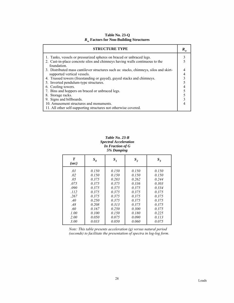
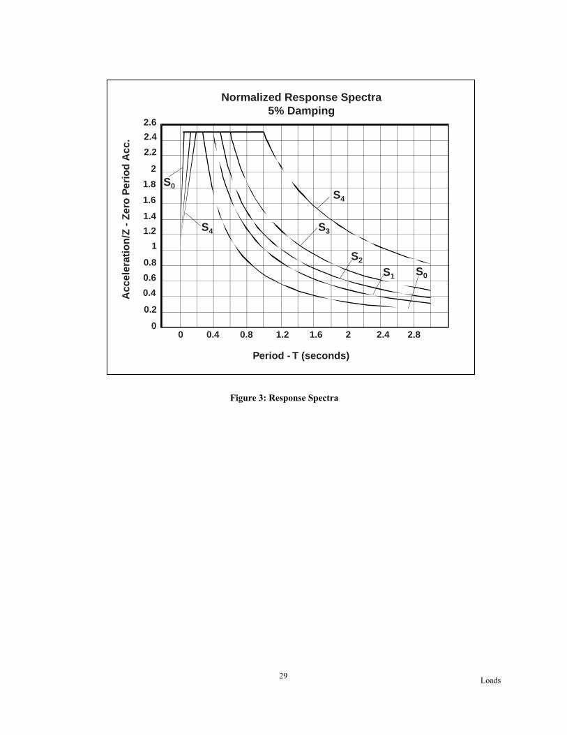
A. For soil profile types S1, S2 and S3, the normalized response spectrum is given in Figure No. 3. For soil
profile type S4, see B. below.B. A site-specific response spectrum based on the geologic, tectonic, seismologic and soil characteristics
associated with the specific site. The spectrum shall be developed for a damping ratio of 0.05 unless a differentvalue is shown to be consistent with the anticipated structural behavior at the intensity of shaking established for thesite. The design of all structures located on a soil type S4 profile shall be based on properly substantiated site-specific spectra.
C. Ground motion time histories developed for the specific site shall be representative of actual earthquakemotions. Response spectra from time histories, either individually or in combination, shall approximate the sitedesign spectrum conforming to Section 2312 (f) 2 B.
D. For structures on Soil Profile Type S4 the following requirements shall apply when required by Section 2312(d) 8 C (iv):
(i) The ground motion representation shall be developed in accordance with paragraphs B and C above.(ii) Possible amplification of building response due to the effects of soil-structure interaction and lengthening
of building period caused by inelastic behavior shall be considered.(iii) The base shear determined by these procedures may be reduced to a design base shear, V, by dividing by a
factor not greater than the appropriate Rw factor for the structure.
E. The vertical component of ground motion may be defined by scaling corresponding horizontal accelerationsby a factor of two thirds. Alternative factors may be used when substantiated by site-specific data.
3. Mathematical model. A mathematical model of the physical structure shall represent the spatial distributionof the mass stiffness of the structure to an extent which is adequate for the calculation of the significant features ofits dynamic response. A three-dimensional model shall be used for the dynamic analysis of structures with highlyirregular plan configurations such as those having a plan irregularity defined in Table No. 23-N and having a rigid orsemirigid diaphragm.
4. Description of analysis procedures. A. Response spectrum analysis. An elastic dynamic analysis of astructure utilizing the peak dynamic response of all modes having a significant contribution to total structuralresponse. Peak modal responses are calculated using the ordinates of the appropriate response spectrum curve whichcorrespond to the modal periods. Maximum modal contributions are combined in a statistical manner to obtain anapproximate total structural response.
B. Time history analysis. An analysis of the dynamic response of a structure at each increment of time whenthe base is subjected to a specific ground motion time history.
5. Response spectrum analysis. A. Number of modes. The requirement of Section 2312(f)4A that allsignificant modes be included may be satisfied by demonstrating that for the modes considered at least 90 percent ofthe participating mass of the structure is included in the calculation of response for each principal horizontaldirection.
B. Combining modes. The peak member forces, displacements, story forces, story shears and base reactions foreach mode shall be combined by recognized methods. When three-dimensional models are used for analysis, modalinteraction effects shall be considered when combining modal maxima.
C. Scaling of results. The base shear for a given direction determined using these procedures, including theappropriate Importance Factor, I, when less than the values below, shall be scaled up to these values.
(i) The base shear shall be increased to the following percentage of the value determined from the proceduresof Section 2312(e), including consideration of the minimum value of C/Rw, except that the coefficient C, fora period, T, greater than 3 seconds, may be calculated as 1.80 S/T:(a) 100 percent for irregular buildings; or(b) 90 percent for regular buildings, except that the base shear shall not be less than 80 percent of that
determined from Section 2312(e) using the period, T, calculated from Method A.

Loads17
All corresponding response parameters, including deflections, member forces and moments, shall be increasedproportionately.
(ii) The base shear for a given direction determined using these procedures need not exceed that required byparagraph (i) above. All corresponding response parameters may be adjusted proportionately.
D. Directional effects. Directional effects for horizontal ground motion shall conform to the requirements ofSection 2312 (e) 1. The effects of vertical ground motions on horizontal cantilevers shall be considered inaccordance with Section 2312 (e) 10. Vertical seismic response may be determined by dynamic response methods;in no case shall the response used for design be less than that obtained by the static method.
E. Torsion. The analysis shall account for torsional effects, including accidental torsional effects as prescribedin Section 2312 (e) 6. Where three-dimensional models are used for analysis, effects of accidental torsion shall beaccounted for by appropriate adjustment in the model such as adjustment of mass locations, or by equivalent staticprocedures such as provided in Section 2312 (e) 6.
F. Dual systems. Where the lateral forces are resisted by a dual system, as defined in Section 2312(d)6E above,the combined system shall be capable of resisting the base shear determined in accordance with this section. Themoment-resisting frame, shear walls and braced frames shall conform to Section 2312(d)6E. The moment-resistingframe may be analyzed using either the procedures of Section 2312 (e)4 or those of Section 2312 (f) 5.
6. Time history analysis. Time history analyses shall meet the requirements of Section 2312(d)10 and theresults shall be scaled in accordance with Section 2312 (f) 5C.
(g) Lateral Force on Elements of Structures and Nonstructural Components Supported by Structures.1. General. Parts and portions of structures and their attachments, permanent nonstructural components and
their attachments, and the attachments for permanent equipment supported by a structure shall be designed to resistthe total design seismic forces prescribed in Section 2312 (g) 2.
Attachments shall include anchorages and required bracing. Friction resulting from gravity loads shall not beconsidered to provide resistance to seismic forces.
When the structural failure of the lateral force-resisting systems of nonrigid equipment would cause a lifehazard, such systems shall be designed to resist the seismic forces prescribed in Section 2312 (g) 2.
EXCEPTION: Equipment weighing less than 400 pounds, furniture, or temporary or movable equipment.
When allowable design stresses and other acceptance criteria are not contained in or referenced by this code inthe U.B.C. Standards, such criteria shall be obtained from approved national standards.
2. Design for total lateral force. The total design lateral seismic force, Fp, shall be determined from thefollowing formula:
Fp = ZICpWp (12-10)
The values of Z and I shall be the values used for the building. EXCEPTIONS: 1. For anchorage of machinery and equipment required for life-safety systems, the valueof I shall be taken as 1.5.2. For the design of tanks and vessels containing sufficient quantities of highly toxic or explosivesubstances to be hazardous to the safety of the general public if released, the value of I shall be taken as1.5.3. The value of I for panel connectors for panels in Section 2312 (h) 2 D (iii) shall be 1.0 for the entireconnector.
The coefficient Cp is for elements and components and for rigid and rigidly supported equipment. Rigid orrigidly supported equipment is defined as having a fundamental period less than or equal to 0.06 second. Nonrigidor flexibly supported equipment is defined as a system having a fundamental period, including the equipment,greater than 0.06 second.
The lateral forces calculated for nonrigid or flexibly supported equipment supported by a structure and locatedabove grade shall be determined considering the dynamic properties of both the equipment and the structure whichsupports it, but the value shall not be less than that listed in Table No. 23-P. In the absence of an analysis orempirical data, the value of Cp for nonrigid or flexibly supported equipment located above grade on a structure shallbe taken as twice the value listed in Table No. 23-P, but need not exceed 2.0.
EXCEPTION: Piping, ducting and conduit systems which are constructed of ductile materials andconnections may use the values of Cp from Table No. 23-P.
Loads18
The value of Cp for elements, components and equipment laterally self-supported at or below ground level maybe two thirds of the value set forth in Table No. 23-P. However, the design lateral forces for an element orcomponent or piece of equipment shall not be less than would be obtained by treating the item as an independentstructure and using the provisions of Section 2312 (i).
The design lateral forces determined using Formula (12-10) shall be distributed in proportion to the massdistribution of the element or component.
Forces determined using Formula (12-10) shall be used to design members and connections which transfer theseforces to the seismic-resisting systems.
For applicable forces in connectors for exterior panels and diaphragms, refer to Section 2312 (h) 2 D and I.Forces shall be applied in the horizontal directions, which result in the most critical loadings for design.3. Specifying lateral forces. Design specifications for equipment shall either specify the design lateral forces
prescribed herein or reference these provisions.4. Essential or hazardous facilities and life-safety systems. For equipment in facilities assigned to Occupancy
Categories I and II and for life-safety systems, the design and detailing of equipment which needs to be functionalfollowing a major earthquake shall consider the effect of drift.
5. Alternative designs. Where an approved national standard or approved physical test data provide a basis forthe earthquake-resistant design of a particular type of equipment or other nonstructural component, such a standardor data may be accepted as a basis for design of the items with the following limitations:
(i) These provisions shall provide minimum values for the design of the anchorage and the members andconnections which transfer the forces to the seismic-resisting system.
(ii) The force, Fp, and the overturning moment used in the design of the nonstructural component shall not beless than 80 percent of the values that would be obtained using these provisions.
(h) Detailed Systems Design Requirements. 1. General. All structural framing systems shall comply with therequirements of Section 2312 (d). Only the elements of the designated seismic-force-resisting system shall be usedto resist design forces. The individual components shall be designed to resist the prescribed design seismic forcesacting on them. The components shall also comply with the specific requirements for the material contained inreference standard RS 10. In addition, such framing systems and components shall comply with the detailed systemdesign requirements contained in Section 2312 (h).
All building components shall be designed to resist the effects of the seismic forces prescribed herein and theeffects of gravity loadings from dead, floor, live and snow loads.
Consideration shall be given to design for uplift effects caused by seismic loads. For materials which useworking stress procedures, dead loads shall be multiplied by 0.85 when used to reduce uplift.
Provision shall be made for the effects of earthquake forces acting in a direction other than the principal axesin each of the following circumstances:
The structure has plan irregularity Type E as given in Table No. 23-N.The structure has plan irregularity Type A as given in Table No. 23-N for both major axes.A column of a structure forms part of two or more intersecting lateral force-resisting systems.
EXCEPTION: If the axial load in the column due to seismic forces acting in either direction is less than20 percent of the column allowable axial load.
The requirement that orthogonal effects be considered may be satisfied by designing such elements for 100percent of the prescribed seismic forces in one direction plus 30 percent of the prescribed forces in the perpendiculardirection. The combination requiring the greater component strength shall be used for design. Alternatively, theeffects of the two orthogonal directions may be combined on a square root of the sum of the squares (SRSS) basis.When the SRSS method of combining directional effects is used, each term computed shall be assigned the sign thatwill result in the most conservative result.
2. Structural framing systems. A. General. Four types of general building framing systems defined in Section2312 (d) 6 are recognized in these provisions and shown in Table No. 23-O. Each type is subdivided by the types ofvertical elements used to resist lateral seismic forces. Special framing requirements are given in this section and inreference standard RS 10.
B. Detailing requirements for combinations of systems. For components common to different structuralsystems, the more restrictive detailing requirements shall be used.
C. Connections. Delete this paragraph.D. Deformation compatibility.(i) All framing elements not required by design to be part of the lateral force-resisting system shall be
investigated and shown to be adequate for vertical load-carrying capacity when displaced 3 (Rw/8) times

Loads19
the displacements resulting from the required lateral forces. P-delta effects on such elements shall beaccounted for. For designs using working stress methods, this capacity may be determined using anallowable stress increase of 1.7. The rigidity of other elements shall also be considered.
(ii) Moment-resistant space frames may be enclosed by or adjoined by more rigid elements which would tendto prevent the space frame from resisting lateral forces where it can be shown that the action or failure ofthe more rigid elements will not impair the vertical and lateral load resisting ability of the space frame.
(iii) Exterior nonbearing, nonshear wall panels or elements which are attached to or enclose the exterior shall bedesigned to resist the forces per Formula (12-10) and shall accommodate movements of the structureresulting from lateral forces or temperature changes. Such elements shall be supported by means of cast-in-place concrete or by mechanical connections and fasteners in accordance with the following provisions:
Connections and panel joints shall allow for a relative movement between stories of not less than two timesstory drift caused by wind, 3(Rw/8) times the calculated elastic story drift caused by design seismic forces, or 1/2inch, whichever is greater.
Connections to permit movement in the plane of the panel for story drift shall be sliding connections usingslotted or oversize holes, connections which permit movement by bending of steel, or other connections providingequivalent sliding and ductility capacity.
Bodies of connections shall have sufficient ductility and rotation capacity so as to preclude fracture of theconcrete or brittle failures at or near welds.
The body of the connection shall be designed for one and one-third times the force determined by Formula (12-10).
All elements of the connecting system such as bolts, inserts, welds, dowels, etc., shall be designed for four timesthe forces determined by Formula (12-10). Fasteners embedded in concrete shall be attached to, or hooked around,reinforcing steel or otherwise terminated so as to effectively transfer the forces.
E. Ties and continuity. All parts of a structure shall be interconnected and the connections shall be capable oftransmitting the seismic force, induced by the parts being connected. As a minimum, any smaller portion of thebuilding shall be tied to the remainder of the building with elements having at least a strength to resist Z/3 times theweight of the smaller portion.
A positive connection for resisting a horizontal force acting parallel to the member shall be provided for eachbeam, girder or truss. This force shall be not less than Z/5 times the dead plus live load.
F. Collector elements. Collector elements shall be provided which are capable of transferring the seismic forcesoriginating in other portions of the building to the element providing the resistance to those forces.
G. Concrete frames. Concrete frames required by design to be part of the lateral force resisting system shall, asa minimum, be intermediate moment-resisting frames, except as noted in Table 23-O.
H. Anchorage of concrete or masonry walls. Concrete or masonry walls shall be anchored to all floors androofs which provide lateral support for the wall. The anchorage shall provide a positive direct connection betweenthe wall and floor or roof construction capable of resisting the horizontal forces specified in Section 2312 (g) orreference standards RS 9-6, 10-1 and 10-2. Requirements for developing anchorage forces in diaphragms are givenin Section 2312 (h) 2 I below. Diaphragm deformation shall be considered in the design of the supported walls.
I. Diaphragms.(i) The deflection in the plane of the diaphragm shall not exceed the permissible deflection of the attached
elements. Permissible deflection shall be that deflection which will permit the attached element to maintainits structural integrity under the individual loading and continue to support the prescribed loads.
(ii) Floor and roof diaphragms shall be designed to resist the forces determined in accordance with thefollowing formula:
F
F
w
wpx
ll x
n
tl x
n px= =
=
∑
∑(12-11)
The force Fpx determined from Formula (12-11) need not exceed 0.75 Z I wpx, but shall not be less than
0.35 Z I wpx.

Loads20
When the diaphragm is required to transfer lateral forces from the vertical resisting elements above thediaphragm to other vertical elements below the diaphragm due to offset in the placement of the elements orto changes in stiffness in the vertical elements, these forces shall be added to those determined fromFormula (12-11).
(iii) Diaphragms supporting concrete or masonry walls shall have continuous ties or struts between diaphragmchords to distribute the anchorage forces specified in Section 2312 (h) 2 H. Added chords may be used toform subdiaphragms to transmit the anchorage forces to the main crossties.
(iv), (v) and (vi): Delete these items.J. Framing below the base. The strength and stiffness of the framing between the base and the foundation shall
not be less than that of the superstructure. The special detailing requirements of reference standards RS 10-3 and RS10-5C, as appropriate, shall apply to columns supporting discontinuous lateral force-resisting elements and toSMRSF, IMRSF and EBF system elements below the base which are required to transmit the forces resulting fromlateral loads to the foundation.
K. Building Separations. All structures shall be separated from adjoining structures. Separation due to seismicforces shall allow for 1 inch displacement for each 50 feet of total building height. Smaller separation may bepermitted when the effects of pounding can be accommodated without collapse of the building.
(i) Non-building Structures. 1. General. A. Non-building structures include all self-supporting structures otherthan buildings which carry gravity loads and resist the effects of earthquake. Non-building structures shall bedesigned to resist the minimum lateral forces specified in this section. Design shall conform to the applicableprovisions of other sections as modified by the provisions contained in Section 2312 (i).
B. The minimum design lateral forces prescribed in this section are at a service level (rather than yield orultimate level). The design of Non-building structures shall provide sufficient strength and ductility, consistent withthe provisions specified herein for buildings, to resist the effects of seismic ground motions as represented by thesedesign forces.
When applicable, allowable stresses and other design criteria shall be obtained from approved nationalstandards.
When applicable design stresses and other design criteria are not contained in or referenced by this code or theU.B.C. Standards, such criteria shall be obtained from approved national standards.
C. The weight W for Non-building structures shall include all dead load as defined for buildings in Section 2312(e) 1. For purposes of calculating design seismic forces in Non-building structures, W shall also include all normaloperating contents for items such as tanks, vessels, bins and piping.
D. The fundamental period of the structure shall be determined by rational methods such as by using Method Bin Section 2312 (e) 2.
E. The drift limitations of Section 2312 (e) 8 need not apply to Non-building structures. Drift limitations shallbe established for structural or nonstructural elements whose failure would cause life hazards. P-delta effects shallbe considered for structures whose calculated drifts exceed the values in Section 2312 (e) 8.
F. In Seismic Zones 3 and 4, structures which support flexible nonstructural elements whose combined weightexceeds 25 percent of the weight of the structure shall be designed considering interaction effects between thestructure and the supported elements.
2. Lateral force. Lateral force procedures for Non-building structures with structural systems similar tobuildings [those with structural systems which are listed in Table No. 23(O).] shall be selected in accordance withthe provisions of Section 2312 (d).
EXCEPTION: Intermediate moment-resisting space frames (IMRSF) may be used in Zones Nos. 3 and 4for Non-building structures in Occupancy Categories III and IV if (1) the structure is less than 50 feet inheight and (2) an Rw = 4.0 is used for design.
Rigid structures (those with period T less than 0.06 second), including their anchorages, shall be designed forthe lateral force obtained from Formula (12-12).
V = 0.5 Z I W (12-12)
The force V shall be distributed according to the distribution of mass and shall be assumed to act in anyhorizontal direction.
3. Tanks with supported bottoms. Flat bottom tanks or other tanks with supported bottoms, founded at orbelow grade, shall be designed to resist the seismic forces calculated using the procedures in Section 2312 (i) forrigid structures considering the entire weight of the tank and its contents. Alternatively, such tanks may be designedusing one of the two procedures described below.

Loads21
A response spectrum analysis, which includes consideration of the actual ground motion anticipated at the siteand the inertial effects of the contained fluid.
A design basis prescribed for the particular type of tank by an approved national standard, provided that theseismic zones and occupancy categories shall be in conformance with the provisions of Sections 2312 (d) 2 and2312 (d) 4, respectively.
4. Other Non-building structures. Non-building structures which are not covered by Section 2312 (i) 2 and 3shall be designed to resist minimum seismic lateral forces not less than those determined in accordance with theprovisions in Section 2312 (e) with the following additions and exceptions:
(i) The factor Rw shall be as given in Table No. 23-Q. The ratio C/Rw used for design shall be not less than0.5.
(ii) The vertical distribution of the lateral seismic forces in structures covered by this section may bedetermined by using the provisions of Section 2312 (e) 4 or by using the procedures of Section 2312 (f). EXCEPTION: For irregular structures assigned to Occupancy Categories I and II which cannot bemodeled as a single mass the procedures of Section 2312 (f) shall be used.
(iii) Where an approved reference standard provides a basis for the earthquake-resistant design of a particulartype of Non-building structure covered by this Section 2312(i)4, such a standard may be used, subject tothe limitations in this subsection:
The occupancy categories shall be in conformance with the provisions of Sections 2312(d)5 and 2312(d)4,respectively.
The values for total lateral force and total base overturning moment used in design shall not be less than 80percent of the values that would be obtained using these provisions.
(j) Earthquake-recording Instrumentations. Delete this paragraph.
Table No. 23-ISeismic Zone Factor Z
ZONE NEW YORK CITY
Z 0.15
Loads22
Table No. 23-JSite Coefficients
TYPE DE S C RI PTI ONS F A C TOR
So
S1
S2
S3
S4
A profile of Rock materials of class I-65 to 3-65.
A soil profile with either: (a) Soft Rock (4- 65) or Hardpan (5-65) or similar material characterized by shear-wave velocity greater than 2500 feet per second, or (b) Medium Compact to Compact Sands (7-65) and Gravels (6-65) or Hard Clays (9-65) where the soil depth is less than 100 feet.
A soil profile with Medium Compact to Compact Sands (7-65) and Gravels (6-65) or Hard Clays (9- 65), where the soil depth exceeds 100 feet.
A total depth of overburden of 75 feet or more and containing more than 20 feet of Soft to Medium Clays (9-65) or Loose Sands (7-65, 8-65) and Silts (10-65), but not more than 40 feet of Soft Clay or Loose Sands and Silts.
A soil profile containing more than 40 feet of Soft Clays (9-65) or Loose Sands (7-65, 8-65), Silts (10- 65) or Uncontrolled Fills (11-65), where the sheer- wave velocity is less than 500 feet per second.
0. 67
1. 0
1. 2
1. 5
2. 5
Notes:
1. The site S Type and corresponding S Factor shall be established from properlysubstantiated geotechnical data with the classes of materials being defined inaccordance with Section 27-675 (C26-1103.1) of the administrative code of the cityof New York.
2. The soil profile considered in determining the S Type shall be the soil on which thestructure foundations bear or in which pile caps are embedded and all underlyingsoil materials.
3. Soil density/consistency referred to in the table should be based on standardpenetration test blow counts (N-values) and taken as: (a) for sands, loose - where Nis less than 10 blows per foot, medium compact - where N is between 10 and 30, andcompact - where N is greater than 30 blows per foot; and (b) for clays, soft - whereN is less than 4 blows per foot, medium - where N is between 4 and 8, stiff to verystiff - where N is between 8 and 30, and hard - where N is greater than 30 blows perfoot.
4. When determining the type of soil profile for profile descriptions that fallsomewhere in between those provided in the above table, the S Type with the largerS factor shall be used.
5. For Loose Sands, Silts or Uncontrolled Fills below the ground water table, thepotential for liquefaction shall be evaluated by the provisions of Section 2312(d) 3.

Loads23
Table No. 23-KOccupancy Categories
OCCUPANCYCATEGORIES
OCCUPANCY TYPE OR FUNCTION OFSTRUCTURE
I. Essential Facilities
II. Hazardous Facilities
III. Special Occupancy Structure
IV. Standard Occupancy Structure
Hospitals and other medical facilities having surgery and emergency treatment areas. Fire and Police stations. Buildings for schools through secondary or day-care centers - capacity > 250 students. Tanks or other structures containing, housing or supporting water or other fire-suppression materials or equipment required for the protection of essential or hazardous facilities, or special occupancy structures. Emergency vehicle shelters and garages. Structures and equipment in emergency-preparedness centers. Stand-by power generating equipment for essential facilities. Structures and equipment in government communication centers and other facilities required for emergency response.
Structures housing, supporting or containing sufficient quantities of toxic or explosive substances to be dangerous to the safety of the general public if released.
Covered structures whose primary occupancy is public assembly - capacity > 300 persons. Buildings for colleges or adult education schools - capacity > 500 students. Medical facilities with 50 or more resident incapacitated patients, but not included above. Jails and detention facilities. All structures with occupancy > 5000 persons, excluding Occupancy Group E buildings. Structures and equipment in power generating stations and other public utility facilities not included above, and required for continued operation.
All structures having occupancies or functions not listed above.
Loads24
Table No. 23-LOccupancy Requirements
OCCUPANCY CATEGORY 1IMPORTANCE FACTOR 2
I
I. Essential facilities II. Hazardous facilities III. Special occupancy structures IV. Standard occupancy structures
1.251.251.01.0
1Occupancy types or functions of structures within each category are listed in Table No. 23-K. Review and inspection requirements are given in Sections 305 and 306.2For life-safety-related equipment, see Sections 2312 (g) I.
Table No. 23-MVertical Structural Irregularities
IRREGULARITY TYPE AND DEFINITION REFERENCESECTION
A. Stiffness Irregularity - Soft Story A soft story is one in which the lateral stiffness is less than 70 percent of that in the story above or less than 80 percent of the average stiffness of the three stories above. B. Weight (mass) Irregularity Mass irregularity shall be considered to exist where the effective mass of any story is more than 150 percent of the effective mass of an adjacent story. A roof which is lighter than the floor below need not be considered. C. Vertical Geometric Irregularity Vertical geometric irregularity shall be considered to exist where the horizontal dimension of the lateral force-resisting system in any story is more than 130 percent of that in an adjacent story. One-story penthouses need not be considered. D. In-Plane Discontinuity in Vertical Lateral Force-resisting Element An in-plane offset of the lateral load-resisting elements greater than the length of those elements. E. Discontinuity in Capacity - Weak Story A weak story is one in which the story strength is less than 80 percent of that in the story above. The story strength is the total strength of all seismic resisting elements sharing the story shear for the direction under consideration.
2312 (d) 8 C (ii)
2312 (d) 8 C (ii)
2312 (d) 8 C (ii)
2312 (e) 7
2312 (d) 9 A

Loads25
Table No. 23-NPlan Structural Irregularities
IRREGULARITY TYPE AND DEFINITION REFERENCESECTION
A. Torsional Irregularity - to be considered when diaphragms are not flexible. Torsional irregularity shall be considered to exist when the maximum story drift, computed including accidental torsion, at one end of the structure transverse to an axis is more than 1.2 times the average of the story drifts of the two ends of the structure. B. Reentrant Corners Plan configurations of a structure and its lateral force-resisting system contain reentrant corners, where both projections of the structure beyond a reentrant corner are greater than 15 percent of the plan dimension of the structure in the given direction. C. Diaphragm Discontinuity Diaphragms with abrupt discontinuities or variations in stiffness, including those having cutout or open areas greater than 50 percent of the gross enclosed area of the diaphragm, or changes in effective diaphragm stiffness of more than 50 percent from one story to the next. D. Out-of-plane Offsets Discontinuities in a lateral force path, such as out-of-plane offsets of the vertical elements. E. Nonparallel Systems The vertical lateral load-resisting elements are not parallel to nor symmetric about the major orthogonal axes of the lateral force-resisting system.
2312 (h) 2 I (v)
2312 (h) 2 I (v)2312 (h) 2 I (vi)
2312 (h) 2 I (v)
2312 (e) 7,2312(h) 2 I (v)
2312 (h) I
Loads26
Table No. 23-OStructural Systems
BASIC STRUCTURAL SYSTEM LATERAL LOAD-RESISTING SYSTEM DESCRIPTION RW
A. Bearing Wall System
B. Building Frame System
C. Moment-resisting Frame System
D. Dual Systems
1. Light-framed walls with shear panels a. Plywood walls for structures three stories or less b. All other light-framed walls 2. Shear Walls a. Concrete b. Reinforced masonry 3. Light steel-framed bearing walls with tension-only bracing 4. Braced frames where bracing carries gravity load a. Steel b. Concrete c. Heavy timber
1. Steel eccentric braced frame (EBF) 2. Light-framed walls with shear panels a. Plywood walls for structures three stories or less b. All other light-framed walls 3. Shear walls a. Concrete b. Reinforced masonry 4. Concentric braced frames a. Steel b. Concrete c. Heavy timber
1. Special moment-resisting frames (SMRF) a. Steel b. Concrete 2. Concrete intermediate moment-resisting frames (IMRF) 3. Ordinary moment-resisting frames (OMRF) a. Steel
b. Concrete4
1. Shear walls a. Concrete with SMRF b. Concrete with steel OMRF c. Concrete with concrete IMRF d. Concrete with concrete OMRF e. Reinforced masonry with SMRF f. Reinforced masonry with steel OMRF g. Reinforced masonry with concrete IMRF 2. Steel eccentric braced frame a. With steel SMRF b. With steel OMRF 3. Concentric braced frames a. Steel with steel SMRF b. Steel with steel OMRF c. Concrete with concrete SMRF d. Concrete with concrete IMRF
86
654
644
10
97
86
888
12128
64
12695867
126
10696
Notes: 1. Basic structural systems are defined in Section 2312 (d) 6. 2. See Section 2312 (e) 3 for combinations of structural systems. 3. See Section 2312 (d) 8C and 2312 (d) 9B for undefined systems.
4. Prohibited with S3 or S4 soil profiles or where the height exceeds 160 feet.

Loads27
Table No. 23-PHorizontal Force Factor Cp
1
ELEMENTS OF STRUCTURES, NONSTRUCTURAL COMPONENTS AND EQUIPMENT VALUEOF Cp
I. Part or Portion of Structure 1. Walls, including the following: a. Unbraced (cantilevered) parapets. b. Other exterior walls above street grade.2
c. All interior bearings walls. d. All interior nonbearing walls and partitions around vertical exits, including offsets and exit passageways. e. Nonbearing partitions and masonry walls in areas of public assembly > 300 people. f. All interior nonbearing walls and partitions made of masonry in Occupancy Categories I, II and III. g. Masonry or concrete fences at grade over 10 feet high. 2. Penthouses (defined in article 2 of subchapter 2 of chapter 1 of title 27 of the building code), except where framed by an extension of the building frame. 3. Connections for prefabricated structural floor and roof elements other than walls (see above) with force applied at center of gravity. 4. Diaphragms.3
II. Nonstructural Components 1. a. Exterior ornamentation and appendages including cornices, ornamental statuaries or similar pieces of ornamentation. b. Interior ornamentation and appendages in areas of public assembly including cornices, ornamental statuaries or similar pieces of ornamentation. 2. Chimneys, stacks, trussed towers, and tanks on legs. a. Supported on or projecting as an unbraced cantilever above the roof more than one-half its total height. b. All others, including those supported below the roof with unbraced projection above the roof less than one-half its height, or braced or guyed to the structural frame at or above its center of mass. 3. Exterior signs or billboards.III. Equipment and Machinery4
1. Tanks and vessels (including contents), including support systems and anchorage.
2.000.750.75
0.750.75
0.750.50
0.75
0.75
--
2.00
2.00
2.00
0.752.00
0.75
Notes:1See Section 2312 (g) 2 for additional requirements for determining Cp for nonrigid equipment or for itemssupported at or below grade.2See Section 2312 (h) 2 D (iii) and Section 2313 (g) 2.3See Section 2312 (h) 2 I.4Equipment and machinery include such items as pumps for fire sprinklers, motors and switch gears for sprinklerpumps, transformers and other equipment related to life-safety including control panels, major conduit ducting andpiping serving such equipment and machinery.
Loads28
Table No. 23-QRw Factors for Non-Building Structures
STRUCTURE TYPE Rw
1. Tanks, vessels or pressurized spheres on braced or unbraced legs.2. Cast-in-place concrete silos and chimneys having walls continuous to the foundation.3. Distributed mass cantilever structures such as: stacks, chimneys, silos and skirt- supported vertical vessels.4. Trussed towers (freestanding or guyed), guyed stacks and chimneys.5. Inverted pendulum-type structures.6. Cooling towers.7. Bins and hoppers on braced or unbraced legs.8. Storage racks.9. Signs and billboards.10. Amusement structures and monuments.11. All other self-supporting structures not otherwise covered.
35
443545534
Table No. 23-RSpectral Acceleration
In Fraction of G5% Damping
T(sec)
S0 S1 S2 S3
.01
.02
.05.075.090.112.267.40.48.601.002.003.00
0.1500.1500.3750.3750.3750.3750.3750.2500.2080.1670.1000.0500.033
0.1500.1500.2830.3750.3750.3750.3750.3750.3130.2500.1500.0750.050
0.1500.1500.2620.3360.3750.3750.3750.3750.3750.3000.1800.0900.060
0.1500.1500.2440.3030.3340.3750.3750.3750.3750.3750.2250.1130.075
Note: This table presents acceleration (g) versus natural period(seconds) to facilitate the presentation of spectra in log-log form.
Loads29
0 0.4 0.8 1.2 1.6 2 2.4 2.8
Normalized Response Spectra5% Damping
Acc
eler
atio
n/Z
- Z
ero
Per
iod
Acc
.
Period - T (seconds)
0
0.2
0.4
0.6
0.8
1
1.2
1.4
1.6
1.8
2
2.2
2.4
2.6
S0
S4
S4
S3
S2
S1 S0
Figure 3: Response Spectra

Loads30
* "N" isUncorrectedvalue,Directly from BoringData
"N" in Blows per Foot*D
epth
in F
eet
0
0 10 20 30
CA B
10
20
30
40
50
Category A: Probable Liquefaction
Category B: Possible Liquefaction
Category C: Liquefaction Unlikely
Figure 4: Potential for Liquefaction of Level Ground

31 Loads/Masonry
2.3 Materials
The following sections refer to standards. Amendments have not been inserted into the original standardsÕ text.
Section 8. The list of referenced national standards of reference standard RS-10 of the appendix to such chapter 1of title 27 of the administrative code of the city of New York is amended by adding eight new standards to read asfollows:
ACI 530/ASCE 5 Building Code Requirements for Masonry Structures,as modified ......................................................................... 1992
ACI 530.1/ASCE 6 Specifications for Masonry Structures, as modified..................... 1992
ANSI/ACI 318 Building Code Requirements for Reinforced Concrete,as modified ......................................................................... 1989
MNL-120 Prestressed Concrete Institute Design Handbook, Third Edition.... 1985
UBC Section 2723 Steel Structures Resisting Forces Induced by Earthquake Motions inSeismic Zones Nos. 1 and 2 with Accumulative Supplement, as modified......................................................................................... 1990
AITC 117 Specification for Structural Glued Laminated Timber of SoftwoodSpecies - Design Standard ..................................................... 1987and Manufacturing Standard.................................................. 1988
APA Form No. L350C Diaphragms - Design / Construction Guide ........................... 1989
APA Form No. E30K Residential & Commercial Design/Construction Guide ..............1989
Section 9. Reference standard RS 10-1 of the appendix to chapter 1 of title 27 of such code is amended bydesignating said standard RS10-1A and amending section 1.1 therein to read as follows:
1.1 Scope. This standard provides minimum requirements for the design and construction of non enlargementalterations to unit masonry in buildings constructed on or before the effective date of this local law as an alternateto RS 10-1B, not including plain or reinforced unit concrete, reinforced gypsum, or reinforced unit masonry. All newconstruction and enlargement alterations in and of themselves of unit masonry on new or existing foundations, notincluding plain reinforced concrete, reinforced gypsum, or reinforced unit masonry shall comply with referencestandard RS 10-1B.
Section 10. Reference standard RS-10 of the appendix to chapter 1 of title 27 of such code is amended byadding new reference standard RS-10-1B to read as follows:
REFERENCE STANDARD RS 10-1BMASONRY
ACI 530-92/ASCE 5-92 Building Code Requirements for Masonry Structures, as modified.ACI 530.1-92/ASCE 6-92 Specifications for Masonry Structures, as modified.
MODIFICATIONS - The provisions of ACI 530-92/ASCE 5-92 shall be subject to the following modifications.The chapter and section numbers are from that standard.

32 Masonry
Chapter 1 - General Requirements
Delete Section 1.3 - Approval of special systems of design or construction
Section 1.4 - Standards cited in this code
Section 1.4.1 Delete "ANSI A58.1-82 - Minimum Design Loads for Buildings and other Structures."
Chapter 5 - General Analysis and Design Requirements
Section 5.2.2 - Delete this section and substitute the following:
5.2.2 Service loads shall be in accordance with the building code of the city of New York of which thisstandard forms a part, with such live load reductions as are permitted in the building code of the city ofNew York. The load provisions of the referenced standards RS 9 shall be used.
Chapter 6 - Design Allowing Tensile Stresses in Masonry
Section 6.1.1 - Delete this section and substitute the following:
6.1.1 The provisions of this chapter are to be applied in conjunction with the provisions of Chapter 5 -General Analysis and Design Requirements and Appendix A.
Section 6.4 - Axial tension
Add the following at the end of section 6.4:
Axial tension stress shall be resisted entirely by steel reinforcement in accordance with Chapter 7.
Chapter 7 - Design Neglecting Tensile Strength of Masonry
Section 7.1.2 - Delete this section and substitute the following:
7.1.2 The provisions of this chapter are to be applied in conjunction with the provisions of Chapter 5 -General Analysis and Design Requirements and Appendix A.
Chapter 9 - Empirical Design of Masonry
Section 9.1.1.1 Seismic - Delete this section and substitute the following:
9.1.1.1 Seismic - Empirical requirements may apply to the design or construction of masonry for buildings,parts of buildings or other structures located in New York City.
Section 9.1.1.2 Wind - Delete this section and substitute the following:
9.1.1.2 Wind - Empirical requirements shall not apply to the design or construction of masonry forbuildings, parts of buildings, or other structures to be located in areas where the basic wind speed willresult in a wind pressure that exceeds 20 psf.
Section 9.2 - Height
Add the following sentence at the end of section 9.2:
33 Masonry
However, members which are not part of the lateral force resisting system of the building are permitted tobe designed in accordance with the provisions of Chapter 9 of RS 10-1B in buildings greater than 35 feet inheight.
Section 9.9 - Miscellaneous requirements
Delete this section and add the following new Chapter 10:
Chapter 10 - Miscellaneous Requirements
10.1 CHASES AND RECESSES - Masonry directly above chases or recesses wider than 12 inches shall besupported on lintels.
10.1.1 Where permitted: Chases and recesses shall be prohibited in any wall less than 12 inches thick and in therequired area of piers and buttresses; except that where permitted in 8-inch walls, in residential buildings and in theapron under window openings, the maximum depth of chases shall be 4 inches.
10.1.2 Maximum size: The maximum permitted depth of a chase in any wall shall not be more than one-third ofthe wall thickness, and the maximum length of a horizontal chase or the maximum horizontal projection of adiagonal chase shall not exceed 4 feet except as provided for in Section 10.1.6; and except further that the maximumlength of the apron below window sills in all walls shall not exceed the width of the window opening. Waterproofedchases in such aprons in 8-inch walls shall not exceed 4 inches in depth. The aggregate area of recesses and chasesshall be not more than one-fourth of the area of the face of the wall in any one story.
10.1.3 Waterproofing chases: The backs and sides of all chases in exterior walls with less than 8 inches ofmasonry to the exterior surface shall be insulated and waterproofed.
10.1.4 Fire resistive limitations: Chases or recesses shall not reduce the thickness of masonry material belowthe minimum equivalent thickness required for firewalls, fire separation assemblies or required fire resistivecoverings of structural members.
10.1.5 Hollow walls: Where chases and recesses are permitted in hollow walls and walls constructed of hollowblocks or tile, the chases and recesses shall be built in with the wall. Chases shall not be cut in hollow walls aftererection.
10.1.6 Continuous chases: Where horizontal chases for the bearing of reinforced concrete floors and roof slabsare continuous, anchors shall be installed above and below the floor construction to resist bending and uplift in thewall due to flexure of the slab.
10.2 LINTELS - The design for lintels shall be in accordance with the provisions of Sections 5.6 and 7.3.3.Minimum end bearing shall be 4 inches.
10.3 SUPPORT ON WOOD - No masonry shall be supported on wood girders or other forms of wood construction.
10.4 CORBELLING
10.4.1 Solid masonry units shall be used for corbelling. The maximum corbelled projection beyond the face ofthe wall shall be not more than one half of the wall thickness or one half the wythe thickness for hollow walls; themaximum projection of one unit shall neither exceed one half the height of the unit nor one third its thickness atright angles to the face which is offset. Corbelling of hollow walls or walls built of hollow units shall be supportedon at least one full course of solid masonry.
10.4.2 Molded cornices: Unless structural support and anchorage are provided to resist the overturningmoment, the center of gravity of all projecting masonry or molded cornices shall lie within the middle one-third of

34 Masonry
the supporting wall. Terra cotta and metal cornices shall be provided with a structural frame of non-combustibleanchored material.
10.5 ARCHES AND LINTELS - The masonry above openings shall be supported by properly buttressed arches orby lintels that bear on the wall at each end for at least 4 inches.
10.6 PARAPET WALLS - All cells in the hollow masonry units and all joints in solid, cavity, or masonry bondedhollow wall construction shall be filled solid with mortar. All corners of masonry parapet walls shall be reinforcedwith joint reinforcement or its equivalent at vertical intervals not greater than 12 inches. Such reinforcement shallextend around the corner for at least 4 feet in both directions and splices shall be lapped at least 6 inches. Parapetwalls shall be properly coped and flashed with noncombustible, weatherproof material of a width not less than thewidth of the parapet wall plus sufficient overage for overlaps. Masonry parapet walls shall be not less than 8 inchesin thickness and their height shall not exceed three times their thickness. Parapet walls shall be designed inaccordance with the provisions of Appendix A.
10.7 ISOLATED PIERS - Isolated masonry piers shall be bonded as required for solid walls of the same thicknessand shall be provided with adequate means for distributing the load at the top of the pier.
10.8 BEARING DETAILS - Concentrated loads shall be supported upon construction of solid masonry, concrete,or masonry of hollow units with cells filled with mortar, grout, or concrete and of sufficient height to distributesafely the loads to the wall or column, or other adequate provisions shall be made to distribute the loads.
10.8.1 Joists: Solid construction for support under joists shall be at least 2 1/4 inches in height and joistssupported on such construction shall extend into the masonry at least 3 inches.
10.8.2 Beams: Solid construction for support under beams, girders, or other concentrated loads shall be at least4 inches in height and the bearing of beams shall extend into the masonry at least 4 inches.
10.9 USE OF EXISTING WALLS - An existing masonry wall may be used in the alteration or extension of abuilding provided that it meets the requirements of this standard.
10.9.1 Walls of insufficient thickness: Existing walls of masonry units that are structurally sound, but that areof insufficient thickness when increased in height, may be strengthened by an addition of similar masonry units laidin type M or S mortar. The foundations and lateral support shall be equivalent to those required for newlyconstructed walls under similar conditions. All such linings shall be thoroughly bonded into existing masonry bytoothings to assure combined action of wall and lining. Toothings shall be distributed uniformly throughout thewall, and shall aggregate in vertical cross-sectional area at least 15 percent of the total surface area of the lining.Stresses in the masonry under the new conditions shall not exceed the allowable stresses.
10.10 PRECAUTIONS DURING ERECTION - Temporary bracing shall be used wherever necessary to take careof any loads to which the walls may be subjected during erection. Such bracing shall remain in place as long as maybe required for safety.
10.11 HORIZONTAL COMPRESSION JOINTS - All concrete framed buildings to be constructed over 35 ft. inheight (as measured from adjoining grade to the main roof level), whose exterior wythe are of cavity wallconstruction with steel lintels, shall have horizontal compression joints in the exterior wythe to prevent masonrydistress induced by vertical shortening of the structural frame.
(a) Unless substantiated as indicated by (b) below, horizontal compression joints shall be 1/4 inch minimumthickness, with neoprene, polyethylene, or urethane gasket or equivalent joint filler filling the entire joint, except fora recess from the toe of the lintel angle to the exterior of the facing brick, to provide space for caulking. These jointsshall be spaced at each floor.
(b) The applicant of record shall submit an engineering analysis establishing that proposed buildingcompression joints as shown on the plans further apart than in (a) above are sufficient to provide for the effects ofvertical shortening of the structural frame.
35 Masonry
10.12 DRY-STACKED, SURFACE-BONDED MASONRY WALLS
10.12.1 General: Dry-stacked, surface-bonded masonry walls may be used for only one and two family dwellingsand shall comply with the requirements of this code for masonry wall construction.
10.12.2 Materials: Surface-bonding mortar shall comply with ASTM C476. Concrete masonry units shall complywith ASTM C55, C90 or C145.
10.12.3 Design: Dry-stacked, surface-bonded masonry walls shall be of adequate strength and proportions tosupport all superimposed loads without exceeding the allowable stresses listed in Table 10.12.3. Allowable stressesnot specified in Table 10.12.3 shall comply with the requirements in this standard.
Table 10.12.3ALLOWABLE STRESS
GROSS CROSS-SECTIONAL AREA_____________________________________________________________________________________________Description Maximum allowable stress
(psi)_____________________________________________________________________________________________Compression
Standard block.............................................................................................................................. 45Shear .......................................................................................................................................... 10
Flexural tensionVertical span ................................................................................................................................ 18Horizontal span ............................................................................................................................ 30
_____________________________________________________________________________________________
10.12.4 Construction: Construction of dry-stacked, surface-bonded masonry walls, including stacking andleveling of units, mixing and application of mortar, curing and protection, shall comply with ASTM C946.
10.13 GLASS-BLOCK WALLS
10.13.1 Exterior wall panels: The maximum dimensions of glass-block wall panels in exterior walls, where usedsingly or in multiples to form continuous bands of glass blocks between structural supports, shall be 25 feet inlength and 20 feet in height between structural supports and expansion joints; and the area of each individual panelshall not be more than 250 square feet. Intermediate structural supports shall be provided to support the dead loadof the wall and all other superimposed loads. Where individual panels are more than 144 square feet in area, asupplementary stiffener shall be provided to anchor the panels to the structural supports.
10.13.2 Joint materials: Glass blocks shall be laid up in Type S or N mortar with approved galvanized metalpanel anchors in the horizontal mortar joints of exterior panels. The sills of glass-block panels shall be coated withapproved water-based asphaltic emulsion, or other elastic waterproofing material, prior to laying the first mortarcourse, and the perimeter of the panels shall be caulked to a depth of not less than 1/2 inch with nonhardeningcaulking compound on both faces, or other expansion joints shall be provided. Where laid up in joint materialsother than mortars herein defined, a single panel shall not be more than 100 square feet in area, nor more than 10feet in either length or height.
10.13.3 Wind and seismic loads: Exterior wall panels held in place in the wall openings shall be designed toresist both the internal and external loads due to wind and seismic loads.
10.13.4 Interior wall panels: Solid or hollow glass blocks shall not be used in fire walls, party walls, fireseparation assemblies or fire partitions, or for loadbearing construction. Such blocks shall be erected with mortarand reinforcement in metal frames, structural channels or embedded panel anchors as provided for exterior walls orother joint materials. All mortar-bearing surfaces of the glass block shall be precoated or prepared to insure

36 Masonry
adhesion between mortar and glass. Wood strip framing shall not be used in fire separation assemblies that arerequired to be fire resistance rated.
EXCEPTIONS: Glass-block assemblies with a material and equipment acceptance number or Board ofStandards and Appeals number having a fire resistance rating of not less than 3/4 hour shall be permittedin fire separations which have a required fire resistance rating of one hour or less and do not enclose exitstairways or exit passageways.
10.14 VENEER
10.14.1 General - Veneer, as used in this section, refers to an exposed facing wythe of brick, tile, ceramicveneer, terra cotta, concrete masonry units, cast stone, natural stone, or similar weather-resistant noncombustiblemasonry units laid in mortar and securely attached to a surface for the purpose of providing ornamentation,protection or insulation, but not intentionally so bonded as to exert common action under load. In lieu of theprovisions of Section 10.14, veneers may be designed according to Chapters 5, 6 and 9 of reference standard RS 10-1B.
10.14.1.1 Limitations: Veneer shall not be assumed to add to the strength of any wall, nor shall it be assumed tosupport any load other than its own weight. No veneer shall be less than the thickness specified in Table 10.14.1.1.The height and length of veneer areas shall be unlimited, except as required to control expansion and contraction,and except as provided in subsection 10.14.2.
TABLE 10.14.1.1 MINIMUM THICKNESSOF MASONRY VENEER
_____________________________________________________________________________________________Minimum Thickness
Type of Veneer Actual (in)_____________________________________________________________________________________________Anchored Type:
Solid masonry units.....................................................................................................................1 5/8Hollow masonry units .................................................................................................................1 5/8Ceramic veneer...............................................................................................................................1
Adhesion Type:Solid masonry units....................................................................................................................... 3/8Ceramic veneer............................................................................................................................ 3/8
_____________________________________________________________________________________________
10.14.1.2 Design: All anchor attachments shall be designed to resist a minimum positive or negative horizontalforce as required for wind or seismic effects, and adhesion type veneer shall be designed to have a bond sufficient towithstand a shearing stress of 50 psi. At a minimum, the veneer shall also meet the attachment requirements ofSection 10.14.2.1 and 10.14.3.1.
10.14.1.3 Support of veneer: The weight of all anchored type veneer shall be supported upon footings,noncombustible foundation walls, or other approved supports. Veneer above openings shall be supported uponnoncombustible, non-corrosive lintels.
10.14.2 Veneer on wood: Anchored masonry veneer attached to wood frame structures shall be supported onnoncombustible footings or foundation walls. The height of the veneer shall not exceed 35 feet measured from thetop of the supporting footings or foundation walls. Where anchored veneer exceeding 20 feet in height is applied, itshall be supported in a manner that will provide for movement between the veneer and it backing.
10.14.2.1 Attachment: At a minimum, veneer of unit masonry shall be attached directly to wood studs, by one ofthe following means:
37 Masonry
a) With at least 22 gauge corrosion-resistance corrugated steel ties at least one inch wide, at vertical intervals ofnot more than 24 inches and horizontal intervals of not more than 32 inches, but in no case less than one tie for 31/2 square feet of wall area;
b) Directly to a 1 inch reinforced cement mortar base.
10.14.3 Veneer on masonry: Veneer attached to masonry or concrete backing shall not be limited in height otherthan by compressive stresses.
10.14.3.1 Attachment: At a minimum, veneer shall be securely attached to the masonry or concrete backing byone of the following means or by a means that is equivalent in strength:
a) Metal ties conforming to Section 5.8 except that ties shall be spaced not more than 24 inches apart eitherhorizontally or vertically;
b) Corrosion-resistant dovetail slot anchors where the backing and the veneer has been designed for this type ofattachment. Such anchors shall be formed from at least 16 gauge steel at least 1 inch wide;
c) Adhesion type masonry veneer shall be installed in accordance with the manufacturer's recommendations andsetting plans;
d) Where anchored veneer is not grouted to the back, it shall be supported in a manner that will provide formovement between the veneer and its backing.
10.15 MISCELLANEOUS STRUCTURES AND SYSTEMS
10.15.1 Flat or Segmental Masonry Floor or Roof Arches: The provisions of this section do not apply whenmasonry floor or roof arches are proportioned on the basis of structural analysis.
10.15.1.1 Span: The maximum clear span between supporting beams shall be 8 feet.
10.15.1.2 Tie Rods: All masonry flat arches or segmental arches shall be provided with tie rods in both theexterior and interior spans. The minimum size and spacing of tie rods shall be:
For exterior spans - 1 1/4 inches round rods spaced 4 feet 6 inches apart.For interior spans - 7/8 inches round rods spaced 4 feet 6 inches apart.Washers shall be used with all tie rods. All tie rods shall have a minimum specified yield point of 36,000 psi.
10.15.1.3 Flat arches: The depth of flat arches of burnt clay or shale hollow blocks shall be at least 1 1/2 inchesfor each foot of span, inclusive of the portion of the block extending below the under side of the beam, and sucharches shall be at least 6 inches thick. Brick shall not be used for flat arches.
10.15.1.4 Segmental arches: Segmental arches shall have a rise of at least 1 inch per foot of span, and theminimum thickness shall be 6 inches for hollow tile arches and 4 in. for brick arches with a span of 5 feet or lessand 8 inches for brick arches with a span exceeding 5 feet.
10.15.1.5 Structural clay tile arches: The blocks shall be at least two cells deep, shall be laid in type M or Smortar, and shall be properly keyed.
10.15.1.6 Brick arches: Brick arches shall be laid in a full bed of type M or S mortar and shall be solidlybonded.
10.15.1.7 Openings in floors and roofs: Suitable metal framing or reinforcement shall be provided in masonryarch and roof construction around any opening more than 1 foot 6 inches on a side.
Delete sections 10.15.2 through 10.15.2.4.

38 Masonry
Appendix A - Special Provisions for Seismic Design
Section A.1.1.1 - Delete this section and substitute the following:A.1.1.1 Appendix A sets special requirements for masonry and construction of masonry building elementsfor seismic design as defined in reference standard RS 9-6.
Section A.2 - Delete this section.
Section A.3 - Delete the words Òfor Seismic Zone 2.Ó
Section A.3.3 - Delete this section and substitute the following:
A.3.3 Distribution of seismic loads or forces shall be in accordance with the provisions of referencestandard RS 9-6.
Section A.3.6 - Delete the first two sentences and substitute the following:
Masonry walls which require lateral forces shown in Table 23-P of reference standard RS 9-6 shall beanchored to all floors and roofs which provide lateral support for the walls. The anchorage of such walls orpartitions shall provide direct connection capable of resisting the forces derived from Table No. 23-P or aminimum of 200 pounds per lineal foot of wall, whichever is greater.
Section A.3.8 - Delete this section and substitute the following:
A.3.8 Vertical reinforcement of at least 0.20 square inches in cross sectional area shall be providedcontinuously from support to support at each corner, at each side of each opening, at the ends of walls andat a maximum spacing of 10 feet apart throughout the wall. Horizontal reinforcement not less than 0.20square inches in cross sectional area shall be provided: (1) at the bottom and top of wall openings andshall extend not less than 24 inches nor less than 40 bar diameters past the opening; (2) continuously atstructurally connected roof and floor levels and at the top of walls; (3) at the bottom of the wall or in thetop of the foundations when doweled to the wall; (4) at maximum spacing of 10 feet unless uniformlydistributed joint reinforcement is provided. Reinforcement at the top and bottom of openings when used indetermining the maximum spacing specified in item (4) above shall be continuous in the wall.
Add the following sections:
A.3.10 Non-bearing back-up or infill walls and non-bearing partitions need not comply with the verticaland horizontal (2 way) reinforcing requirements of section A.3.8 if the requirements set forth in A.3.10.1through A.3.10.4 are met.
A.3.10.1 The cross sectional area of uniformly spaced steel reinforcing in either the horizontal or thevertical direction shall equal or exceed 0.0005 times the gross cross sectional area of the masonry.
A.3.10.2 Reinforcement shall be continuous between supports.
A.3.10.3 Spacing of prescribed horizontal reinforcement shall not exceed 16 inches for joint reinforcement,and 4 feet for reinforcement bars in grouted bond beams. When vertical reinforcement is used, bars shallnot exceed placement at 10 feet on center and at the ends of walls.
A.3.10.4 Lateral support anchorage shall be provided between the non-loadbearing back-up, infill orpartition wall and its structural support. Spacing of anchors shall conform to the provisions of Sections 4.2and 5.11 and shall not exceed the spacing of prescribed reinforcement. Anchorage shall be designed totransfer lateral (out-of-plane) forces to the adjacent structural support.
Section A.4 - Delete this section.
39 Masonry/Reinforced Masonry/Reinforced Concrete
MODIFICATIONS - The provisions of ACI 530.1-92/ASCE 6-92 shall be subject to the following modifications.The chapter and section numbers are from that standard.
Section 2.3.1 - Inspection and testing - Delete the opening sentence and substitute the following:
Inspection shall conform to the requirements of Articles 1.5 and 1.6, the inspection and testing provisions ofthe building code of the city of New York, and the following:
Section 11. Reference standard RS 10-2 of the appendix to chapter 1 of title 27 and of the administrative code of thecity of New York is REPEALED and reenacted to read as follows:
REFERENCE STANDARD RS 10-2REINFORCED MASONRY
ACI 530-92/ASCE 5-92 Building Code Requirements for Masonry Structures, as modified.
ACI 530.1-92/ASCE 6-92 Specifications for Masonry Structures, as modified.
MODIFICATIONS - The provisions of ACI 530-92 and ACI 530.1-92 shall be subject to the same modificationsas set forth in reference standard RS 10-1B and shall apply to reinforced masonry.
EXCEPTION - For buildings designed utilizing reinforced masonry construction in existence on theeffective date of this local law, repairs or alterations to the facade or interior of the structure shall be donein accord with ACI 530-92/ASCE 5-92 Building Code Requirements for Masonry Structures, as modifiedand ACI 530.1-92/ASCE 6-92 Specifications for Masonry Structures, as modified except for thoseprovisions found in Appendix A Special Provisions for Seismic Design.
Section 12. Reference standard RS 10-3 of the appendix to chapter 1 of title 27 of such code is REPEALED andreenacted to read as follows:
REFERENCE STANDARD RS 10-3ACI 318-1989 BUILDING CODE REQUIREMENTS FOR REINFORCED CONCRETE
Comments - The Commentary on Building Code Requirements for Reinforced Concrete (ACI 318-89) may be usedas a guide for interpreting this standard.
MODIFICATIONS - The provisions of ACI 318-89 shall be subject to the following modifications. The sectionand subdivision numbers are from that standard.
Chapter 1 General Requirements
Delete section 1.2.1 and substitute the following:
1.2.1 - The applicable provisions of the building code of the city of New York shall apply.
Delete section 1.2.2.
Delete section 1.2.3.
Delete section 1.3.1 and substitute the following:
1.3.1 - The applicable provisions of the building code shall apply.
Delete section 1.3.2.
Delete section 1.3.4.
Delete this section 1.4 and substitute the following:
40 Reinforced Concrete
1.4 - The provisions of the building code for equivalent systemsÊ of design shall apply.
Chapter 3 Specifications for Tests and Materials
Delete section 3.1.3.
Delete section 3.6.6 and substitute the following:
3.6.6 - Fly Ash may be used in lieu of Chemical Admixtures (ASTM C494) RS 10-44.
Chapter 5 Concrete Quality, Mixing and Placing
Section 5.1.1
Delete "5.3.2" on the second line and insert the words "Section 5.6.1.6 as listed", and delete the lastsentence.
Section 5.1.2
Delete "5.6.2" on the second line and insert the words "the NewÊ York City Building Code".
Section 5.2.1(c)
Delete "5.6" on the second line and insert the words "the New York City Building Code".
Delete section 5.2.3.
Section 5.3
Delete the words "and/or trial mixtures".
Section 5.3.1
Delete the words "Standard deviation" and insert the words "Method II Proportioning on the basis of fieldexperience".
Section 5.3.1.1(c)
Delete the words "except as provided in 5.3.1.2".
Delete section 5.3.1.2 in its entirety, including Table 5.3.1.2.
Section 5.3.2.1
Delete "or 5.3.1.2" at the end of the sentence.
Delete section 5.3.2.2. in its entirety, including Table 5.3.2.2.
Section 5.3.3
Delete the words "several strength test records, or trial mixtures" at the end of the sentence.
41 Reinforced Concrete
Section 5.3.3.1
Delete the third sentence starting with the words "For the purpose of" and ending with the words "less than45 days".
Section 5.3.3.2
Add a period on the third line after the word "mixtures", delete the remainder of the section, and add thefollowing sentence: "The Trial mixtures shall conform to the provisions of Section 27-605(a)(3) of the NewYorkÊ City Building Code."
Delete section 5.4.1 and substitute the following:
Proportioning shall conform to New York City Building Code Section 27-605 (a) Method I.
Delete Table 5.4 in its entirety.
Delete section 5.4.2.
Delete section 5.4.3.
Delete section 5.5 (b).
Delete section 5.6.1.1 and substitute the following:
5.6.1.1 - Whenever strength tests of concrete specimens are required by the provisions of the building codeof the city of New York, compression test samples shall be taken directly from the mixer in accordance withreference standard RS 10-51, cured in accordance with reference standard RS 10-52, and tested at the ageof 28 days or as otherwise specified in accordance with reference standard RS 10-17.
Delete section 5.6.1.2 and substitute the following:
5.6.1.2 - Three test specimens shall be molded for each 50 cubic yards or fraction thereof for each class ofconcrete placed in any one day's concreting. In addition, concrete test specimens shall be made fromconcrete taken out of the bucket, hopper or forms as directed by the engineer designated for controlledÊinspection. These test specimens shall be separate and distinct from those made from the mixer and shall bemade from the same batch and cured and tested in the same manner as described above for the samplestaken from the mixer.
Delete section 5.6.1.3 and substitute the following:5.6.1.3 - The number of test specimens made from the concrete taken out of the bucket, hopper or forms may bereduced to a minimum of one set of three (3) specimens for every 150 cubic yards, or fraction thereof, for eachclass of concrete placed in any one day's concreting. When the concrete is being placed directly from the mixerinto the forms without any intermediate conveyance, the above additionalÊ specimens will not be required.
Delete section 5.6.1.4 and substitute the following:
5.6.1.4 - Additional specimens may be molded and tested where there is a question as to the requiredinterval between placing of concrete and stripping forms or placing the structure into use.
Add section 5.6.1.5:
5.6.1.5 - The test specimens shall be tested by a licensed concrete testing laboratory. The testing of eachÊbatch of three specimens shall be considered one strength test. The strength of such test shall be theaverage of the breaking strengths of the three specimens comprising the test, except that if one of thespecimens shall manifest evidence of improper sampling, molding, handling or testing, it shall be discarded
42 Reinforced Concrete
and the remaining two averaged. If more than one specimen must be discarded, the entire strength testshall be voided.
Add section 5.6.1.6:
5.6.1.6 - The average of all sets of three consecutive strength tests representing each class of concrete shallbe equal or greater than the specified strength (f 'c) and not more than 10% of the strength tests shall havevalues less than the specified strength, but no test shall show an average strength less than 85% of thespecified strength.
Delete section 5.6.2.1.
Delete section 5.6.2.2.
Section 5.6.2.3
After the word "satisfactory" in the second line, delete the remainder of the section and add the words "ifthe provisions of Section 5.6.1.6 are met".
Delete section 5.6.2.4.
Section 5.6.3.1
Delete the words "Building Official" on the first line and insert the word "Commissioner".
Section 5.6.4.1
Delete the first three lines through the words "[Section 5.6.2.3(b)]", and substitute the following: "If tests oflaboratory cured specimens fail to conform to the requirements of Section 5.6.1.6 refer to Section 5.6.3.4.Ó
Section 5.6.4.2
Delete the words "strength test more than 500 psi below specified value of f 'c" and insert the words "set ofthree specimen tests which fail to conform to the requirements of Section 5.6.1.6.Ó
Add section 5.9.3:
5.9.3 - Conveying by pumping methods shall be in accordance with the applicable provisions of theBuilding Code.
Section 5.10.4
Add a period on the second line after the word "used", delete the words "unless approved by the Engineer"and add the following sentence: "For additional requirements see applicable provisions of the BuildingCode Section 27-607(a)(2).Ó
Add the following section:
5.14 SPECIAL REQUIREMENTS FOR HIGH STRENGTH CONCRETE
5.14.1 All high strength concrete (6000 PSI and higher) shall be proportioned and manufactured only inaccordance with the provisions of Building Code Section 27-605(b) Method II Proportioning on the basisof field experience.
5.14.2 All high strength concrete specimens shall be made utilizing metal or plastic molds that comply withreference standard RS 10-52. Each test shall consist of eight specimens taken directly from the mixer. Two

43 Reinforced Concrete
specimens shall be tested at seven days, three at 28 days and three at 56 days. These requirements are inaddition to the hopper specimens as required by the Building Code.
5.14.3 At the time of placement of high strength concrete, two concrete production facilities shall beavailable. Said facilities shall have been previously approved by the architect or engineer designated forcontrolled inspection.
5.14.4 All high strength concrete for columns shall be of normal weight concrete.
5.14.5 The requirements of Section 10.13.4 shall be adhered to in all respects.
5.14.6 Where lightweight concrete is to be used for the floor system, the columns and the beam or slab"sandwich" immediately above the columns shall be stone concrete, placed in accordance with therequirements of Section 10.13.
5.14.7 The engineer will insure that there are no cold joints at the interface between the lightweightconcrete and stone portions of the slabs or beams.
5.14.8 All data shall be submitted periodically to the Department of Buildings for review.
Chapter 6 Formwork, Embedded Pipes and Construction Joints
Add the following section:
6.1.7 For additional form work requirements, see applicable provisions of Building Code Section 27-1035.
Add the following sections:
6.3.13 Concrete cover over electrical cables and snow melting pipes in sidewalks shall meet therequirements of the Bureau of Highways of the Department of Transportation.
6.3.14 No conduits, pipes or other similar embedded items will be permitted in prestressed or post-tensionconcrete members other than as shown on the plans as filed with the Department of Buildings or on shopdrawings reviewed by the engineer of record.Ê Computations demonstrating the effects of such embeddeditems on the structural adequacy of prestressed or post-tensioned concrete shall be submitted.
Chapter 10 Flexure and Axial Loads
Add the following section:
10.13.4 When the specified compressive strength of concrete in a column is greater than 1.4 times thatspecified for a floor system, the following additional requirements shall be adhered to:
(a) All of the design provisions of Section 10.13 (unmodified) are adhered to.(b) Application is made to the Borough Superintendent in each individual case.(c) The concrete construction is supervised and inspected continuously by a full-time Professional Engineer
responsible for controlled inspection of concrete and not in the regular employ of the owner orcontractor. Such engineer shall perform no other work during the construction of the particularbuilding nor shall he delegate his responsibility to any subordinates. (d) The Professional Engineerreferred to in subdivision (c) above, without incurring any personal liability, shall be authorized tostop construction, reject any concrete, direct that the concrete testing laboratory being used bedismissed and a new laboratory be retained.

44 Reinforced Concrete/Precast Concrete/Steel
(e) Affidavits by the parties involved shall be filed with and acceptable to the Borough Superintendent priorto approval of any plans.
Chapter 12 Development and Splices of Reinforcement
Add the following section:
12.1.3. Development (Section 12.2) and splice lengths (Section 12.5) computed based on the minimumrequirements of the ACI 318-83 code are deemed equally applicable for usage.
Chapter 16 Precast Concrete
Delete section 16.4.2 and substitute the following:
16.4.2 Lifting devices shall have a capacity sufficient to support four times the appropriate portion of themembers dead weight. The inclination of the lifting force shall be considered.
Delete section 16.4.2.1.
Delete section 16.4.2.2.
Delete section 16.4.2.3.
Chapter 21 Reinforced Concrete Structure Resisting Forces Induced by Earthquake Motions
Add the following sentence to the beginning of section 21.2.1.2:
New York City is to be considered in a region of moderate risk.
Section 13. Reference standard RS 10-4 of the appendix to chapter 1 of title 27 of such code is REPEALED andreenacted to read as follows:
REFERENCE STANDARD RS 10-4PRECAST CONCRETE AND PRESTRESSED CONCRETE
ACI 318-1989 Building Code Requirement for Reinforced ConcreteMNL-120-1985 Prestressed Concrete Institute Design Handbook, Third Edition.MODIFICATIONS - The applicable section of ACI Ê318-89 as modified by the applicable provisions of
reference standard RS 10-3 shall apply for precast concrete and prestressed concrete.
Section 14. Reference standard RS-10 of the appendix to such chapter, title and code is amended by adding anew reference standard RS10-5C to read as follows:
REFERENCE STANDARD RS 10-5CSTEEL STRUCTURES RESISTING EARTHQUAKE FORCES
The following text includes the amendments to the 1988 UBC within the text of the UBC provisions. Theseamendments are shown in italics.
UBC SECTION 2723-1990 Steel Structures Resisting Forces Induced by Earthquake Motions in Seismic ZonesNos. 1 and 2 with Accumulative Supplement
MODIFICATIONS - The provisions of UBC Section 2723 shall be subject to the following modifications. Thesubdivisions, paragraphs, subparagraphs and items are from that standard.
45 Steel
Sec. 2723. (a) General. Design and construction of steel framing in lateral force resisting systems shall conform tothe requirements of this reference standard. The use of reference standard RS 10-5B is prohibited for the design ofseismic resisting elements.
(b) Definitions.ALLOWABLE STRESSES are prescribed in reference standard RS 10-5A.CHEVRON BRACING is that form of bracing where a pair of braces located either above or below a beam
terminates at a single point within the clear beam span.CONNECTION is the group of elements that connect the member to the joint.DIAGONAL BRACING is that form of bracing that diagonally connects joints at different levels.ECCENTRIC BRACED FRAME (EBF) is that form of braced frame where at least one end of each brace
intersects a beam at a point away from the column girder joint.GIRDER is the horizontal member in a seismic frame. The words beam and girder may be used
interchangeably.JOINT is the entire assemblage at the intersections of the members.K BRACING is that form of bracing where a pair of braces located on one side of a column terminates at a
single point within the clear column height.LINK BEAM is that part of a beam in an eccentric braced frame which is designed to yield in shear and/or
bending so that buckling of the bracing members is prevented. STRENGTH is the strength as prescribed in reference standard RS 10-5A.V BRACING is that form of chevron bracing that intersects a beam from above and inverted V bracing is that
form of chevron bracing that intersects a beam from below.X BRACING is that form of bracing where a pair of diagonal braces cross near midlength of the bracing
members.(c)1. Materials. Materials shall be as prescribed in reference standard RS 10-5A. Structural steel designed to be
part of the lateral force resisting system of multistory buildings shall not have a specified yield strength greater than50,000 psi.
2. Member Strength. When these provisions require that the strength of the member be developed, the followingshall be used:
Members StrengthFlexure Ms = ZFy
Shear Vs = 0.55Fydt
Axial compression Psc = 1.7Fa A
Axial tension Pst = Fy A
Connectors:Full penetration welds Fy APartial penetration and fillet welds 1.7* AllowableBolts 1.7* Allowable
Members need not be compact unless otherwise required by this chapter.(d) Ordinary Moment Frame Requirements. Girder-to-column connections of ordinary moment frames shall
meet the requirements of paragraph 1 of Special Moment-resisting Frame (SMRF) Requirements unless it can beshown that they are capable of resisting the combination of gravity loads and 3 (Rw/8) times the design seismicforces.
(e) Special Moment-resisting Space Frame (SMRSF) Requirements. 1. Girder to column connection. A.Required Strength. The girder to column connection shall be adequate to develop the lesser of the following:
(i) The strength of the girder in flexure.
(ii) The moment corresponding to development of the panel zone strength, defined as:
46 Steel
V = 0.55Fydct (1 + 3bctcf 2/dbdct)
where:t = the total thickness of the joint panel zone including doubler platesd = the depth of the beamdc = the column depthb = the width of the column flange tcf = the thickness of the column flange.
EXCEPTION: Where a connection is not designed to contribute flexural resistance at the joint, it neednot develop the required strength if it can be shown to meet the deformation compatibility requirements ofSection 2312 (h) 2 D.
B. Connection strength. The girder-to-column connection may be considered to be adequate to develop theflexural strength of the girder if it conforms to the following:
(i) The flanges have full penetration butt welds to the columns.(ii) The girder web-to-column connection shall be capable of resisting the girder shear determined for the
combination of gravity loads and the seismic shear forces which result from compliance with Section 2723(e) A. This connection strength need not exceed that required to develop gravity loads plus 3 (Rw/8) timesthe girder shear resulting from the prescribed seismic forces.
Where the flexural strength of the girder flanges is greater than 70 percent of the flexural strength of the entiresection (i.e., bt (d-tf)Fy >0.7ZxFy) the web connection may be made by means of welding or high-strength bolting.
For girders not meeting the criteria in the paragraph above, the girder web-to-column connection shall be madeby means of welding the web directly or through shear tabs to the column. That welding shall have a strengthcapable of developing at least 20 percent of the flexural strength of the girder web. The girder shear shall be resistedby means of additional welds or friction-type high-strength bolts or both.
C. Alternate connection. Connection configurations utilizing welds or high-strength bolts not conforming withparagraph B above may be used if they are shown by test or calculation to meet the criteria in paragraph A above.Where conformance is shown by calculation, 125 percent of the strengths of the connecting elements may be used.
D. Flange detail limitations. For steel whose specified strength is less than 1.5 times the specified yieldstrength, plastic hinges shall not form at locations in which the beam flange area has been reduced, such as for boltholes. Bolted connections of flange plates of beam-column joints shall have the net-to-gross area ratio Ae/Ag equal
to or greater than 1.25y/Fu.2. Trusses in SMRSF. Trusses may be used as horizontal members in SMRSF if the sum of the truss seismic
force flexural strength exceeds the sum of the column seismic force flexural strength immediately above and belowthe truss by a factor of at least 1.25. For this determination, the strengths of the members shall be reduced by thegravity load effects. In buildings of more than one story, the column axial stress shall not exceed 0.4Fy and the ratioof the unbraced column height to the least radius of gyration shall not exceed 60. The connection of the truss chordsto the column shall develop the lesser of the following:
A. The strength of the truss chord.B. The chord force necessary to develop 125 percent of the flexural strength of the column.3. Girder-column joint restraint. A. Restrained joint. Where it can be shown that the column of SMRSF
remain elastic, the flanges of the columns need be laterally supported only at the level of the girder top flange.Columns may be assumed to remain elastic if one of the following conditions is satisfied:
(i) ( )S Z F f SZ F 1 0c yc a b yb/ / .− >
where (fa > 0).
(ii) The flexural strength of the column is at least 1.25 times the moment that corresponds to the panel zone shearstrength.
(iii) Girder flexural strength of panel zone strength will limit column stress (fa + fbx + fby ) to Fy of the column.
(iv) The column will remain elastic under gravity loads plus 3(Rw/8) times the prescribed seismic forces.
47 Steel
Where the column cannot be shown to remain elastic, the column flanges shall be laterally supported at the levelsof the girder top and bottom flanges. The column flange lateral support shall be capable of resisting a force equal toone percent of the girder flange capacity at allowable stresses (and at a limiting displacement perpendicular to theframe of 0.2 inch). Required bracing members may brace the column flanges directly or indirectly through thecolumn web or the girder flanges.
B. Unrestrained joint. Columns without lateral support transverse to a joint shall conform to the requirements ofSection 1.6.2 of reference standard RS 10-5A with the column considered as pin ended and the length taken as thedistance between lateral supports conforming with A above. The column stress, fa, shall be determined from gravityloads plus the lesser of the following:
(i) 3(Rw/8) times the prescribed seismic forces.(ii) The forces corresponding to either 125 percent of the girder flexural strength or the panel zone shear strength.The stress fby, shall include the effects of the bracing force specified in Section 2723(f)3A as well as P-delta
effects.L/r for such columns shall not exceed 60.At truss frames, the column shall be braced at each truss chord for a lateral force equal to one percent of the
compression yield strength of the chord.4. Changes in beam flange area. Abrupt changes in beam flange area are not permitted within possible plastic
hinge regions of special moment-resistant frames.5. Drift Calculations. Drift calculations shall include bending and shear contributions from the clear girder and
column spans, column axial deformation, and the rotation and distortion of the panel zone. EXCEPTIONS: 1. Drift calculations may be based on column and girder centerlines where either of thefollowing conditions is met: a. It can be demonstrated that the drift so computed for frames of similar configuration is typically within15 percent of that determined above. b. The column panel zone strength can develop 0.8 Σ/Ms of the girders framing to the column flanges atthe joint. 2. Column axial deformations may be neglected if they contribute less than 10 percent to the total drift.
(f) Requirements for Braced Frames. 1. General. The provisions of this section apply to all braced frames,except eccentrically braced frames (EBF) designed in accordance with Section 2722 (h). Those members whichresist seismic forces totally or partially by shear or flexure shall be designed in accordance with Section 2723 (e).
2. Bracing members. A. Stress Reduction. The allowable stress, Fas, for bracing members resisting seismicforces in compression shall be determined from the following formula:
Fas = βFa (22-4)
WHERE:
Fa = the allowable axial compressive stress allowed in 1.5.1.3 and Section 1.5.6 of reference standard RS10-5A.
β = the stress reduction factor determined from the following formula:
β = 1/ [1 + ([KL/r] /2Cc)] > 0.8
B. Built-up members. The L/r of individual parts of built-up bracing members between stitches, when computedabout a line perpendicular to the axis through the parts, shall not be greater than 75 percent of the L/r of the memberas a whole.
C. Compression elements in braces. The width-thickness ratio of stiffened and unstiffened compressionelements used in braces shall be shown in 1.9 of reference standard RS 10-5A.
3. Bracing connections. A. Forces. Bracing connections shall be designed for the lesser of the following:(i) The tensile strength of the bracing. (ii) 3(Rw/8) times the force in the brace due to the prescribed seismic forces.(iii) The maximum force that can be transferred to the brace by the system. Beam-to-column connections for
beams that are part of the bracing system shall have the capacity to transfer the force determined above.

48 Steel
B. Net Area. In bolted brace connections, the ratio of effective net section area to gross section area shall satisfythe formula:
A
A
1 2 F
Fe
g u
= . *a
(22-6)
WHERE:
Ac = effective net area as defined in Section 2711 (b) 2.F* = stress in brace as determined in Section 2723 (f) 3 A.Fu = Minimum tensile strength.α = fraction of the member force from Section 2723 (f) 2 A that is transferred across a particular net section.
4. Bracing configuration for chevron and K bracing. A. Bracing members shall be designed for 1.5 times theotherwise prescribed forces.
B. The beam intersected by chevron braces shall be continuous between columns.C. Where chevron braces intersect a beam from below, i.e., inverted V brace, the beam shall be capable of
supporting all tributary gravity loads presuming the bracing not to exist. EXCEPTION: This limitation need not apply to penthouses, one-story buildings or the top story ofbuildings.
5. One- and two-story buildings. Braced frames not meeting the requirements of Sections 2723 (g) 2 and 3 maybe used if they are designed for forces of 3 (Rw /8) times the code equivalent static forces at code-allowable seismicstresses.
6. Non-building Structures. Non-building structures with Rw values defined by Table No. 23-Q, need onlycomply with the provisions of Section 2723 (f) 3.
(g) Eccentrically Braced Frames (EBF). EBFs shall comply with the requirements of Section 2722 (h).(h) Nondestructive Testing. Shall comply with the provisions of reference standard RS 10-5A.

49 Timber
TIMBER
Section 15. The first paragraph of section 10 of reference standard RS 10-9 of the appendix to chapter 1 of title27 of the administrative code of the city of New York is amended to read as follows:
Plywood diaphragms may be used to resist horizontal forces in horizontal and vertical distributing orresisting elements, provided the deflection in the plane of the diaphragm, as determined by calculations,tests, or analogies drawn therefrom, does not exceed the permissible deflection of attached distributing orresisting elements. Diaphragms to resist earthquake loads may be designed and constructed inaccordance with reference standard RS 10-58.
Section 16. Reference standard RS 10-18 of the appendix to chapter 1 of title 27 of such code is amended byadding three new standards to read as follows:
ANSI/AITC A190.1-1983 Structural Glued Laminated Timber and AITC 200-1983Inspection Manual.
AITC 117-1987 Specification for Structural Glued Laminated Timber ofSoftwood Species - Design Standard.
AITC 117-1988 Specification for Structural Glued Laminated Timber ofSoftwood Species - Construction Standard.
Section 17. Reference standard RS-10 of the appendix to chapter 1 of title 27 of such code is amended byadding a new reference standard RS 10-58 to read as follows:
REFERENCE STANDARD RS 10-58
APA Form No. L350C-1989 Diaphragms - Design/Construction Guide.APA Form No. E30K-1989 Residential & Commercial, Design/Construction Guide.
Section 18. This local law shall take effect one year after it shall have been enacted into law and shall apply toall buildings for which an application for the approval of plans for the construction of such building has been filedwith the department of buildings on or after the effective date of this local law.