section 23 50 11 - boiler plant mechanical … 23 50 11.docx · web vieweach boiler shall have a...
TRANSCRIPT

11-01-17
SECTION 23 50 11BOILER PLANT MECHANICAL EQUIPMENT
SPEC WRITER NOTES:1. Delete between // // if not
applicable to project. Also delete any other item or paragraph not applicable in the Section and renumber the paragraphs.
2. References to pressure in this section are gauge pressure unless otherwise noted.
3. The spec writer shall review the Physical Security and Resiliency Design Manual for VA Facilities to determine and include any Mission Critical or Life Safety requirements called out.
4. Contract drawings must include (as applicable) the VA National CAD Standards listed below:SD235011-01 Flash TankSD235011-02 Chemical Feed System, Pumped TypeSD235011-05 Boiler Blowoff TankSD235011-06 Water Sample Coolers – Boiler Water and FeedwaterSD235011-07 Continuous Blowdown Heat Recovery Standard Piping DiagramSD235011-08 Boiler Chemical Feed System – Shot TypeSD235011-10 Anchoring Equipment Packaged Boiler and Deaerator and Condensate Storage Tanks
PART 1 - GENERAL1.1 DESCRIPTION
A. Feedwater deaerator, condensate and boiler feed pumps, condensate
storage tank, fuel oil pumping and heating, compressed air systems,
blowoff tank, blowdown heat recovery, chemical treatment systems, steam
vent silencer, and other equipment that supports the operation of the
boilers.
B. A complete listing of common acronyms and abbreviations are included in
Section 23 05 10, COMMON WORK RESULTS FOR BOILER PLANT AND STEAM
GENERATION.
1.2 RELATED WORKA. Section 01 00 00, GENERAL REQUIREMENTS.
B. Section 01 33 23, SHOP DRAWINGS, PRODUCT DATA, AND SAMPLES.
C. Section 01 81 13, SUSTAINABLE CONSTRUCTION REQUIREMENTS.
D. //Section 01 91 00, GENERAL COMMISSIONING REQUIREMENTS.//
23 50 11 - 1

11-01-17
E. Section 09 91 00, PAINTING.
F. //Section 13 05 41, SEISMIC RESTRAINT REQUIREMENTS FOR NON-STRUCTURAL
COMPONENTS.//
G. Section 22 31 11, WATER SOFTENERS.
H. Section 22 67 21, WATER DEALKALIZING SYSTEM.
I. Section 23 05 10, COMMON WORK RESULTS FOR BOILER PLANT AND STEAM
GENERATION.
J. Section 23 05 51, NOISE AND VIBRATION CONTROL FOR BOILER PLANT.
K. Section 23 07 11, HVAC AND BOILER PLANT INSULATION.
L. //Section 23 08 00, COMMISSIONING OF HVAC SYSTEMS.//
M. //Section 23 08 11, DEMONSTRATIONS AND TESTS FOR BOILER PLANT.//
N. Section 23 09 11, INSTRUMENTATION AND CONTROL FOR BOILER PLANT.
O. Section 23 09 23, DIRECT-DIGITAL CONTROL SYSTEM OR HVAC.
P. Section 23 21 11, BOILER PLANT PIPING SYSTEMS.
Q. Section 26 29 11, MOTOR CONTROLLERS.
1.3 APPLICABLE PUBLICATIONSSPEC WRITER NOTE: Make material requirements agree with requirements specified in the referenced Applicable Publications. Verify and update the publication list to that which applies to the project, unless the reference applies to all mechanical systems. Publications that apply to all mechanical systems may not be specifically referenced in the body of the specification, but, shall form a part of this specification.
A. The publications listed below form a part of this specification to the
extent referenced. The publications are referenced in the text by the
basic designation only. Where conflicts occur these specifications and
the VHA standard will govern.
B. American Society of Mechanical Engineers (ASME):
B16.9-2012..............Factory-Made Wrought Buttwelding Fittings
B16.34-2013.............Valves Flanged, Threaded and Welding End
PTC 12.3-1997...........Performance Test Code on Deaerators
ASME Boiler and Pressure Vessel Code – BPVC Section
VIII-2015..........Rules for Construction of Pressure Vessels,
Divisions 1 and 2
C. American Society for Testing and Materials (ASTM):
A53/A53M-2012...........Standard Specification for Pipe, Steel, Black
and Hot-Dipped, Zinc-Coated, Welded and Seamless
23 50 11 - 2

11-01-17
A106/A106M-2015.........Standard Specification for Seamless Carbon Steel
Pipe for High Temperature Service
A234/A234M-2015.........Standard Specification for Piping Fittings of
Wrought Carbon Steel and Alloy Steel for
Moderate and High Temperature Service
A285/A285M-2012.........Standard Specification for Pressure Vessel
Plates, Carbon Steel, Low- and Intermediate–
Tensile Strength
A414/A414M-2014.........Standard Specification for Steel, Sheet, Carbon,
and High-Strength, Low-Alloy for Pressure
Vessels
A515/A515M-2010 (R2015).Standard Specification for Pressure Vessel
Plates, Carbon Steel, for Intermediate- and
Higher-Temperature Service
A516/A516M-2010 (R2015).Standard Specification for Pressure Vessel
Plates, Carbon Steel, for Moderate- and Lower-
Temperature Service
D. Environmental Protection Agency (EPA):
CFR 40, 264.193-2014....Containment and Detection of Releases
E. Department of Health and Human Services, Food and Drug Administration
(FDA):
CFR 21, 175.300-2015....Resinous and Polymeric Coatings
F. Society for Protective Coatings (SSPC):
SP 5-2007...............White Metal Blast Cleaning
G. Underwriters Laboratories (UL):
574-2003 (R2014)........Standard for Electric Oil Heaters
H. Department of Veterans Affairs (VA):
PG-18-10-2016...........Physical Security and Resiliency Design Manual
VHA Boiler Plant Safety Devices Testing Manual, Third Edition
1.4 SUBMITTALSA. Submittals, including number of required copies, shall be submitted in
accordance with Section 01 33 23, SHOP DRAWINGS, PRODUCT DATA, AND
SAMPLES.
B. Information and material submitted under this section shall be marked
“SUBMITTED UNDER SECTION 23 50 11, BOILER PLANT MECHANICAL EQUIPMENT”,
with applicable paragraph identification.
C. Manufacturer's Literature and Data including: Full item description and
optional features and accessories. Include dimensions, weights,
23 50 11 - 3

11-01-17
materials, applications, standard compliance, model numbers, size, and
capacity.
D. Feedwater Deaerator with Storage Tank and Accessories:
1. Drawings showing arrangement and overall dimensions of feedwater
deaerator including storage tank. Show locations of tank-mounted
devices. Show locations and sizes of pipe connections and access
openings. Show design of all shell, head and nozzle welds. Show
access platforms as required for all maintenance and inspection
points.
2. Weight of entire assembly empty and flooded.
3. Catalog data, drawings and specification sheets showing design and
construction of feedwater deaerator, storage tank, recycle pumps,
water flow control valves, safety valve, overflow control valve,
water level and overflow control systems, vent orifice, vacuum
breaker, alarm switches and all accessories.
4. Design flow capacity, oxygen removal rate, and other performance data
and pressure and temperature limitations of feedwater deaerator,
recycle pumps, water flow/level control valve and control system,
safety valve, overflow control valve, vent orifice, vacuum breaker,
alarm switches and all accessories, to include lockout/tagout points.
5. Catalog data on oxygen test kit.
6. Oxygen sample and chemical feed probe design.
7. Deaerator inlet pressure requirements - steam and water.
SPEC WRITER NOTE: Delete the following subparagraphs if not applicable.
8. //Packaged feedwater deaerator/feedwater pump units: Boiler feedwater
pump suction and discharge pipe sizing and arrangement. Design of
support framework and access platforms. Pumps shall have a minimum of
762 mm (30 inches) center to center clearance and 1800 mm (6 foot)
clearance above pumps. Any one pump/motor combination shall be
removable without disassembly of any other pumps or components.
Provide lifting attachments as required to rig pump assemblies out of
frame of the assembly.//
9. //Seismic Restraint Data: Seismic design of support framework for
packaged system. Refer to Section 13 05 41, SEISMIC RESTRAINT
REQUIREMENTS FOR NON-STRUCTURAL COMPONENTS.//
23 50 11 - 4

11-01-17
E. Condensate Storage Tank and Accessories:
1. Drawings showing arrangement and overall dimensions of tank and
supports. Show locations and sizes of all pipe connections and access
openings. Access platforms as required for maintenance and
inspections and operation of the equipment or parts thereof.
2. Weight of entire assembly empty and flooded.
3. Design and construction (including pressure and temperature
limitations) of tank, continuous blowdown heat exchanger (if
provided), control valves, water level control system, level alarm
switches and all accessories, to include lockout/tagout points.
4. Performance data on control valves and continuous blowdown heat
exchanger (if provided). Refer to drawings (Schedules) for
requirements.
5. Interior Coating: Material specification, service limitations,
instructions for application, experience record under the required
service conditions.
SPEC WRITER NOTE: Delete the following subparagraph if not applicable.
6. //Continuous blowoff heat exchanger tube bundles: Dimensions, design,
construction, heating surface, performance data.//
F. Blowoff Tank and Accessories, Flash Tank:
1. Drawing showing outline dimensions, arrangement and weight of tank
and accessories. Locations and sizes of all pipe connections and
access openings.
2. Design and construction of tank, supports and accessories.
3. Design and performance of blowoff tank temperature control valve.
G. Boiler Feed and Condensate Transfer Pumps:
1. Drawings with dimensions of assemblies of pumps and drivers.
2. Catalog data and specification sheets on design and construction of
pumps, drivers and couplings (flexible-coupled units).
3. Motor efficiency and power factor at full load.
4. Performance curves showing discharge head, required flow plus
recirculation, net positive suction head required, efficiency, driver
power, impeller diameter to be furnished. Refer to drawings for
requirements.
5. Pressure and temperature limitations of pump unit and accessories.
6. Size and capacity of recirculation orifice.
23 50 11 - 5

11-01-17
7. Data on variable frequency drive (VFD) units and pressure controllers
(if VFD specified).
H. Condensate Return Pumps (Electrical and/or Mechanical Types) and Vacuum
Heating Pump Units:
1. Drawings with dimensions of entire unit. Drawing shall include
locations and sizes of all pipe connections.
2. Catalog data and specification sheets on design and construction of
pumps, receiver and accessories.
3. Catalog cuts and schematic diagram of controls.
4. Electric pump performance curves showing discharge head, flow, net
positive suction head required, efficiency, motor power and impeller
diameter to be furnished. Mechanical pump performance showing
discharge head, flow, required inlet head and steam pressure. Refer
to drawings for requirements.
5. Pressure and temperature limitations of pump unit.
I. Fuel Oil Pumping Equipment:
1. Drawings with overall dimensions and arrangement of pumps, motors,
couplings, bases, drip pans, duplex strainer, relief valves, back-
pressure control valve, entire fuel oil heating system (if provided)
and supports and all accessories.
2. Catalog data and specification sheets on the design and construction
of pumps, motors, couplings, bases, drip pans, duplex strainer,
relief valves, back pressure control valves, all valves and
accessories.
3. Motor efficiency and power factor at full load.
4. Pressure and temperature limitations of pumps, duplex strainer,
relief valves, back pressure control valve and all valves.
5. ASTM number and pressure rating of pipe and fittings.
6. Performance data on pumps including discharge head, flow, suction
lift and motor power required at viscosity range shown. Refer to
drawings for requirements.
7. Sound level test data on similar pump in similar installation. Refer
to Section 23 05 51, NOISE AND VIBRATION CONTROL FOR BOILER PLANT.
8. Performance data on relief valves and back-pressure control valves.
9. Pump systems below grade or the flood plain shall be 100 percent
waterproof and designed for continued operation if submerged.
23 50 11 - 6

11-01-17
J. Fuel Oil Heaters and Accessories:
1. Drawings with dimensions and arrangement of heaters, temperature
control valves, relief valves, supports and all accessories. Show
locations and sizes of all piping connections.
2. Clearances required for tube removal.
3. Catalog data and specification sheets on the design and construction
of heaters, temperature control valves, relief valves, electric
controls and all accessories.
4. Pressure and temperature limitations of heaters, temperature control
valves and relief valves.
5. Steam trap capacity requirements and selection.
6. Material (ASTM No.) and pressure rating of pipe and fittings.
7. Performance data of heaters including oil flow, pressure loss,
temperature rise, and amount of steam or electricity required.
8. Performance data on relief valves and temperature control valves.
K. No. 2 Fuel Oil Temperature Control System:
1. Drawing with dimensions and arrangement of pumps, motors, heaters,
relief valves and accessories.
2. Catalog data and specification sheets on the design and construction
of pumps, motors, heaters and controls.
3. Pressure and temperature limitations of pumps, heaters, valves,
fittings, strainers and relief valves.
4. Material (ASTM No.) and pressure rating of pipe and fittings.
5. Performance data on oil pumps including discharge head, flow, suction
lift and motor power required at viscosity range shown. Refer to
drawings for requirements.
6. Performance data on relief valves.
L. Compressed Air System:
1. Drawing with dimensions and arrangement of air compressor, motor, air
dryer, receiver and all accessories.
2. Catalog data and specification sheets on the design and construction
of air receiver, compressor, after-cooler, motor, air dryer, all
accessories, condensate traps. Solenoid valves and filters.
3. Performance data on compressors, after coolers, air dryer, relief
valves.
M. Steam Vent Silencer (Muffler):
1. Drawings with silencer dimensions and weights, and sizes and types of
pipe connections.
23 50 11 - 7

11-01-17
2. Catalog data and specification sheets on the design and construction.
3. Sound attenuation data at required flow rates.
N. Boiler Water and Deaerator Water Sample Coolers:
1. Drawings with dimensions, and sizes and location of piping
connections.
2. Catalog data and specification sheets on the design and construction.
3. Pressure and temperature limitations.
4. Amount of heat exchange surface.
O. Chemical Feed Systems:
1. Drawings with dimensions of entire unit which may be field installed
or factory packaged prewired/pre-piped on skid. Include locations and
sizes of tanks, pumps, control panels, all pipe connections, and
injection nozzles or quills //at the deaerators// //at the boilers//.
2. Catalog data and specification sheets on the design and construction
of injection quills, metering pumps, storage tanks, and controls.
3. Performance data on pump including head, flow, motor power. //Refer
to schedules on drawings for requirements.//
4. Pressure and temperature limitations of unit and accessories.
5. Information on suitability of materials of construction for chemicals
to be utilized.
6. Each boiler shall have a dedicated metering pump and injection quill
for each chemical. No blending of chemical treatments is allowed.
Chemicals are to be supplied individually and injected individually
to each boiler and to each treatment point to include //boiler//
steam line and deaerators. Chemicals needed for chemical lay-up of
the boilers such as an oxygen scavenger shall have one dedicated
metering pump that can be valved to inject any boiler directly.
P. Automatic Continuous Blowdown Control System:
1. Drawings with arrangement and dimensions of entire unit. Include
locations and sizes of all pipe connections.
2. Catalog data and specification sheets on design and construction of
conductivity sensor, control valves, controller.
3. Performance data on control valves.
4. Pressure and temperature limitations of valves and conductivity
sensor.
Q. Test Data – Acceptance Tests, on-site: Four copies all specified tests.
23 50 11 - 8

11-01-17
R. Complete operating and maintenance manuals including wiring diagrams,
technical data sheets, information for ordering replacement parts, and
troubleshooting guide:
1. Include complete list indicating all components of the systems.
2. Include complete diagrams of the internal wiring for each item of
equipment.
3. Diagrams shall have their terminals identified to facilitate
installation, operation and maintenance.
S. //Completed System Readiness Checklist provided by the Commissioning
Agent and completed by the contractor, signed by a qualified technician
and dated on the date of completion, in accordance with the requirements
of Section 23 08 00, COMMISSIONING OF HVAC SYSTEMS.//
T. //Submit training plans and instructor qualifications in accordance with
the requirements of Section 23 08 00, COMMISSIONING OF HVAC SYSTEMS.//
1.5 AS-BUILT DOCUMENTATIONSPEC WRITER NOTE: Coordinate O&M Manual requirements with Section 01 00 00, GENERAL REQUIREMENTS. O&M manuals shall be submitted for content review as part of the close-out documents.
A. Submit manufacturer’s literature and data updated to include submittal
review comments and any equipment substitutions.
B. Submit operation and maintenance data updated to include submittal
review comments, VA approved substitutions and construction revisions
shall be //in electronic version on CD or DVD// inserted into a three-
ring binder. All aspects of system operation and maintenance procedures,
including applicable piping isometrics, wiring diagrams of all circuits,
a written description of system design, control logic, and sequence of
operation shall be included in the operation and maintenance manual. The
operations and maintenance manual shall include troubleshooting
techniques and procedures for emergency situations. Notes on all special
systems or devices shall be included. A List of recommended spare parts
(manufacturer, model number, and quantity) shall be furnished.
Information explaining any special knowledge or tools the owner will be
required to employ shall be inserted into the As-Built documentation.
SPEC WRITER NOTE: Select and edit one of the bracketed options after the paragraph below to indicate the format in which the contractor must provide record drawing files. Select the hand-marked option only when the designer has been separately
23 50 11 - 9

11-01-17
contracted to provide the record drawings from the contractor’s mark-ups. Select the BIM option only when a BIM model will be generated, which is typically only performed by the designer on some Design-Bid-Build projects or by the contractor on some Design-Build projects.
C. The installing contractor shall maintain as-built drawings of each
completed phase for verification; and, shall provide the complete set at
the time of final systems certification testing. Should the installing
contractor engage the testing company to provide as-built or any portion
thereof, it shall not be deemed a conflict of interest or breach of the
‘third party testing company’ requirement. Provide record drawings as
follows:
1. //Red-lined, hand-marked drawings are to be provided, with one paper
copy and a scanned PDF version of the hand-marked drawings provided
on CD or DVD.//
2. //As-built drawings are to be provided, with a copy of them on
AutoCAD version // // provided on CD or DVD. The CAD drawings shall
use multiple line layers with a separate individual layer for each
system.//
3. //As-built drawings are to be provided, with a copy of them in three-
dimensional Building Information Modeling (BIM) software version //
// provided on CD or DVD.//
D. The as-built drawings shall indicate the location and type of all
lockout/tagout points for all energy sources for all equipment and pumps
to include breaker location and numbers, valve tag numbers, etc.
Coordinate lockout/tagout procedures and practices with local VA
requirements.
E. Certification documentation shall be provided to COR 21 working days
prior to submitting the request for final inspection. The documentation
shall include all test results, the names of individuals performing work
for the testing agency on this project, detailed procedures followed for
all tests, and provide documentation/certification that all results of
tests were within limits specified. Test results shall contain written
sequence of test procedure with written test results annotated at each
step along with the expected outcome or setpoint. The results shall
include all readings, including but not limited to data on device (make,
model and performance characteristics), normal pressures, switch ranges,
23 50 11 - 10

11-01-17
trip points, amp readings, and calibration data to include equipment
serial numbers or individual identifications, etc.
PART 2 - PRODUCTSGENERAL
Electric motor control cabinets/enclosures including VFDs in the boiler
plant shall be minimum NEMA 4 or better. The design AE shall determine
at the design stage based on the environmental condition and location.
This shall also be indicated on the drawings.
2.1 FEEDWATER DEAERATOR WITH STORAGE TANK AND ACCESSORIESSPEC WRITER NOTES:1. Select tray and packed column-type
deaeration except where available headroom is insufficient to accommodate their height. These types provide good performance over a wide load range.
2. Spray-types that utilize recycle pumps to provide a constant flow rate through the spray nozzles also provide good performance over a wide load range. However, the operating cost of the recycle pump is a disadvantage.
A. Pressurized 14 to 35 kPa (2 to 5 psig) unit designed to heat and
deaerate boiler feedwater by direct contact with low pressure steam.
//Tray or packed column// //Spray// type deaerating section. Horizontal
feedwater storage tank. Provide recycle spray water pumps on spray-type
units if necessary to obtain required performance. Provide accessories
including vacuum breaker, safety valve, water inlet and overflow
controls and control valves, water level indicators and alarms and other
devices as specified and shown.
B. Performance and Operating Characteristics:
1. Oxygen Content of Feedwater Output: 7 ppb maximum over turndown range
with minimum and normal feedwater input temperatures as listed.
2. Turndown: 20/1.
3. Required Maximum Feedwater Flow Output: // // kg/sec (// //
lb/hr).
4. No carbon dioxide in feedwater output; maximum steam vent loss 1/2
percent of input steam at maximum load.
5. Feedwater Input Temperature: Minimum temperature is 15 degrees C (59
degrees F) and normal range is 60 to 82 degrees C (140 to 180 degrees
F).
23 50 11 - 11

11-01-17
6. Water Pressure Loss Through Spray Valves: 48 kPa (7 psig) maximum.
7. Steam Pressure Loss in Unit: 6.9 kPa (1 psig) maximum.
C. Feedwater Storage Capacity to the Overflow Line: Sufficient for twenty
minutes operation at maximum required feedwater output with no input
water, unless shown otherwise on the drawings. Overflow line (elevation)
shall be set by feedwater deaerator manufacturer so that there is no
water hammer when water is at this level.
D. Construction:
SPEC WRITER NOTE: The pressure vessel construction and inspection requirements comply with recommendations of NACE International, the society of corrosion engineers, to reduce the potential for cracking of feedwater deaerator pressure vessel welds. This problem has been recognized for many years and there have been many reports of cracked welds and some catastrophic failures.
1. Storage Tank and Deaerator Pressure Vessels:
a. Conform to ASME BPVC Section VIII. Design for saturated steam at
345 kPa (50 psig) with 3.2 mm (0.125 inch) corrosion allowance.
b. Carbon steel, ASTM A285/A285M Grade C or ASTM A516/A516M Grade 70.
Weld metal strength shall approximate the strength of the base
metal. All welds shall be double-vee type. No single vee welds
allowed. Weld undercuts are prohibited. All welding must be
constructed to allow future internal weld inspections, utilizing
non-destructive-testing methods.
c. Post Weld Heat Treatment (PWHT) to stress-relieve pressure vessel
to 620 degrees C (1148 degrees F) not to exceed ASME hold-time or
temperature.
d. Provide 100 percent radiography of all longitudinal and
circumferential welded seams. Test nozzle-to-shell welds by wet
magnetic-particle method. Hydrostatically test final assembly at
1.3 times design pressure.
e. Furnish completed applicable ASME Forms U-1, U-1A or U-2.
f. Provide a sacrificial magnesium anode for cathodic protection
against corrosion.
g. Provide a vacuum breaker.
2. Trays (Tray-Type Units): Stainless steel, Type 430, no spot welds.
3. Column Packing Material (Packed-Column Units): Stainless steel.
23 50 11 - 12

11-01-17
4. Spray Valve Assemblies: Spring-loaded, guided stem, stainless steel
and Monel, removable. Spring-loaded, guided stem types not required
on spray-type units that operate with recycle pumps at constant flow
rates through the spray valves.
5. All other parts in deaerator section exposed to undeaerated liquids
or gases must be constructed of stainless steel, cupro-nickel or
equivalent.
6. Provide two 300 mm (12 inches) x 406 mm (16 inches) elliptical
manways in storage tank, located below the normal water level, but
near the tank centerline, and away from the deaeration section or
internal piping. Manway locations must allow unrestricted access to
tank interior with no interference from internal equipment and piping
and with easy access from outside the tank. Second manway is to
facilitate the annual internal inspections. Provide permanent access
platforms as required.
7. Provide access openings in deaeration section to allow inspection and
replacement of trays, spray valve assemblies, column packing.
8. Support: Steel saddles or legs welded to storage tank with minimum
height to provide for the net positive suction head required of the
pumps selected. Coordinate location with structural design of
building.
9. Nameplates: Attach to bracket projecting beyond field-applied
insulation. Provide all ASME pressure vessel nameplate information as
required by the Code along with information identifying the designer
and manufacturer of the storage tank and the deaeration section.
10. Pipe Connections:
a. Threaded for sizes 50 mm (2 inches) and under.
b. Flanged, 1035 kPa (150 psig) ASME, for sizes above 50 mm (2
inches).
c. Vortex breaker in boiler feedwater pump suction connection.
d. Overflow Pipe:
1) Overflow pipe inside tank terminating 150 mm (6 inches) below
low-level alarm set point. Operation of overflow control system
must not allow water level to fall to the level of the overflow
pipe inlet.
2) Overflow pipe sizing, based on required maximum feedwater flow
output of feedwater deaerator:
Feedwater Feedwater Overflow Pipe Overflow Pipe
23 50 11 - 13
11-01-17
Flow Rate (kg/sec)
Flow Rate (klb/hr)
Minimum Size (mm)
Minimum Size (in)
0 to 3.8 0 to 30 75 3
3.9 to 7.6 31 to 60 100 4
7.7 to 12.6 61 to 100 150 6
SPEC WRITER NOTE: Delete the following paragraph if tray or packed column-type feedwater deaerator is required. The paragraph applies only to spray-type units.
E. //Recycle Pumps:
1. Provide when necessary to obtain required deaeration performance on
spray-type feedwater deaerators. Provide complete electric service.
2. Pumps: Two required, each full flow capacity of deaerator. High
efficiency, multi-stage diffuser type. Provide valves to isolate each
pump and provide inlet strainer with valved blowdown on each pump.
Provide pressure gauges on suction and discharge of each pump. Refer
to Section 23 09 11, INSTRUMENTATION AND CONTROL FOR BOILER PLANT,
for gauge requirements.
3. Motors: High efficiency, open drip proof. Non-overloading at any
point on pump head-flow performance curve. For efficiency and power-
factor requirements, refer to Section 23 05 10, COMMON WORK RESULTS
FOR BOILER PLANT AND STEAM GENERATION.//
SPEC WRITER NOTES:1. In addition to the safety valve mounted
on the feedwater deaerator, provide sufficient safety valve capacity on the steam pressure reducing valve (PRV) station serving the feedwater deaerator to protect the deaerator from overpressure if a PRV fails wide open or the PRV bypass is wide open. Set pressure 103 kPa (15 psig).
2. The feedwater deaerator safety valve capacity is based on possible excess steam flow from a blowing steam trap connected to the high-pressure drip return. Set pressure should be 69 kPa (10 psig) (lower than the PRV safety valves).
F. Steam Safety Valve: Mount on feedwater deaerator pressure vessel. Set
pressure 103 kPa (15 psig). Capacity as shown. If not shown, minimum
23 50 11 - 14

11-01-17
capacity 0.11 kg/sec (900 lb/hr). For safety valve construction
requirements, refer to Section 23 21 11, BOILER PLANT PIPING SYSTEMS.
G. Oxygen and Non-Condensable Gas Venting: Straight vertical pipe extending
through roof from deaeration section. Provide gate valve in vent pipe,
with hole drilled in wedge. Hole size selected by feedwater deaerator
manufacturer for normal venting with gate valve closed.
H. Thermometers and Pressure Gauges: Refer to Section 23 09 11,
INSTRUMENTATION AND CONTROL FOR BOILER PLANT for construction
requirements. Provide thermometers on deaeration section and on storage
tank. Provide compound gauge with shut-off valve and siphon on
deaerator.
I. Vacuum Breaker: Sized by deaerator manufacturer to protect unit. Bronze
body construction with bronze internal trim, chemical resistant silicone
seat disc and an atmospheric vent, rated for 1035 kPa (150 psig).
J. Water Sample and Chemical Feed Probes: Type 304 or 316 stainless steel,
multi-ported, minimum length 300 mm (1 foot), accessible for removal
from exterior of tank.
K. Dissolved Oxygen Test Kit: Provide a colorimetric-comparator type kit,
utilizing Rhodazine D methodology, for use during acceptance testing and
for future use by the VAMC. The kit shall include self-filling ampoules,
color comparator, oxygen-resistant tubing, sampling devices, sealed
glass ampoules containing reagent, carrying case, all equipment
necessary for complete test. Range 0-20 ppb of dissolved oxygen.
L. Cleaning and Painting: Remove all foreign material to bare metal. Coat
exterior of pressure vessel with rust-preventative primer. Refer to
Section 09 91 00, PAINTING. Do not coat interior of pressure vessel.
M. Insulation: Field-applied. Refer to Section 23 07 11, HVAC AND BOILER
PLANT INSULATION.
SPEC WRITER NOTE: Delete the following paragraph, if not applicable.
N. //Seismic Design: Refer to Section 13 05 41, SEISMIC RESTRAINT
REQUIREMENTS FOR NON-STRUCTURAL COMPONENTS. Design the entire assembly
and anchorage to building to resist seismic forces and be fully
operational after the seismic event.//
O. Water Level Indicators:
SPEC WRITER NOTE: Choose the type of water level indicator.
23 50 11 - 15

11-01-17
1. //Gauge Glasses: Red line type, overlapping glasses if multiple
glasses are utilized. Provide automatic offset-type gauge valves that
stop the flow if a glass is broken. Drain cock on lower gauge valve.
Gauge glass protecting rods.//
2. //Magnetic Float-Flag Type Water Level Gauge:
a. Tubular level gauge with internal float using concentric magnet
with stiffening rings. Float sequentially actuates magnetic flags
to indicate water level. Flags anodized black on one side, gold on
the other, with internal magnet.
b. Flags magnetically interlocked with mechanical stops to allow only
180-degree rotation.
c. Standpipe to be Schedule 40, 304 stainless steel with side type
process connections for maximum visibility of gauge.
d. Bottom connection 100 mm (4 inch) flange with drain plug.
Clearance between floor and bottom flange sufficient for removal
of float.
e. Switches for signals to be SPDT, 5-amp rating.//
3. Vertical pipe type header shall be connected to top and bottom of
storage tank with tank isolation valves and valved header drain.
Viewable gauges shall cover entire diameter of tank.
4. Minimum rating 121 degrees C, 200 kPa (250 degrees F, 29 psig).
P. Low Level Alarm Switch: Float type unit with magnetically actuated
switch. Locate external to tank on a vertical header with valved tank
connections and valved drain. Switch elevation shall be at the tank
centerline. Minimum rating 121 degrees C, 200 kPa (250 degrees F, 29
psig). Provide signals to //annunciator system// //computer
workstation// specified in Section 23 09 11, INSTRUMENTATION AND CONTROL
FOR BOILER PLANT.
Q. High Level Alarm Switch and Overflow Control Switch:
1. Conductivity probe type electronic level switches providing relay
contacts for separate high-level alarm operation and overflow control
valve operation completely separate from control system for inlet
water flow control valves. Overflow control valve shall automatically
open when the water level rises approximately 100 mm (4 inches) above
the high-water alarm level. Provide high level and overflow signals
to //annunciator system// //computer workstation// specified in
Section 23 09 11, INSTRUMENTATION AND CONTROL FOR BOILER PLANT.
23 50 11 - 16

11-01-17
2. The principle of operation shall be differential resistivity of steam
and water at the operating temperatures and pressures. The system
shall include electronics unit, electrodes, special cable between the
electrodes and electronics unit, and electrode cover. The unit shall
be designed to fail safe.
3. Electronics Unit:
a. Each unit shall be capable for signal discrimination of two
electrode channels.
b. Each electrode and its associated circuitry shall be powered by an
independent power source. Power distribution system within the
electronics shall be separate for each channel with its own
transformer and shall be electrically isolated from other
channels.
c. Input power 110 V, 60 Hz, single phase.
d. All input power to each electrode shall be a low voltage, low
frequency ac voltage. dc voltages are prohibited because this may
cause electroplating at the electrodes.
e. The signal discrimination and fault detection system for each
electrode channel shall be independent of the other channel and
any fault in the electronics circuitry of one channel shall not be
transferred to the other channel.
f. The system shall have a continuous on-line fault detection system.
The following faults shall be detected: Electrode failure,
contamination from dirt on electrodes, electrode open circuit
failure, electrode cable short to ground, electrode cable ground
sense failure, power source failure, any electronic component
failure. Electronic circuitry not monitored by the fault detection
system shall be provide with triple redundancy, where the circuit
shall continue to operate and provide contact output with up to
two component failures.
g. Faults shall be annunciated through separate NO and NC contacts.
h. The front of the unit shall have a LED display for each electrode
channel indicating steam or water and status of each electrode.
i. NEMA 4 or better enclosure suitable for operating temperature of -
20 to 70 degrees C (-4 to 158 degrees F), with up to 100 percent
relative humidity.
23 50 11 - 17

11-01-17
4. Electrodes:
a. Suitable for 121 degrees C, 200 kPa (250 degrees F, 29 psig)
minimum. Material shall be stainless steel or better, smooth
length threaded only allowed on end, and corrosion resistant.
b. Electrodes without gaskets are preferred.
c. Teflon insulator media.
d. Electrodes fitted into shrouded inserts which are directly welded
onto the stand-pipe. Design to minimize faulty indication due to
falling condensate into the electrodes.
5. Electrode Cable:
a. Pure nickel wires for at least the first two meters at the
electrode end, with pure nickel crimps. PTFE insulation capable of
withstanding up to 260 degrees C (500 degrees F).
b. Continuous cables from the electrodes to the electronic unit. No
junction boxes allowed.
R. Overflow Water Control Valve and Controller: Open-shut electric or
electronic actuated overflow control valve actuated by conductivity
probe-type water level sensor and control system.
1. Performance: When water level reaches the overflow level as set by
the feedwater deaerator manufacturer, automatically open the overflow
control valve to reduce the water level. Automatically close the
overflow valve when the water level has been lowered to a point 100
mm (4 inches) below the high-level alarm set point. Valve operational
speed shall not exceed 30 seconds for 90-degree valve movement.
2. Controller: Automatic control shall be from the high-level alarm and
overflow control switch system. Provide a manual/auto switch on the
main instrument panel that indicates valve position. Communicate
valve position with computer work station. Control valve shall fail
open. A limit switch on the valve actuator shall initiate alarm on
control station and in computer work station when valve is open.
3. Control Valve:
a. High performance butterfly valve, double offset design.
b. Carbon steel 17-4PH steel valve body conforming to ASME B16.34,
Class 150, lug style, 316 stainless steel nitrided disc.
c. Self-energizing TFE seat providing bubble-tight shut off service
on vacuum and low pressure and pressure sealed for high pressures.
Bi-directional seating.
d. Packing adjustable, chevron design with TFE seals.
23 50 11 - 18

11-01-17
e. 7 kPa (1 psig) maximum pressure loss at maximum flow rate (120
percent of peak deaerator capacity if valve flow and pressure drop
is not scheduled).
4. Valve Actuator:
a. Control module shall accept direct digital control input 4-20 mA
or 2-10 VDC from controller. Module to provide 4-20 mA output for
feedback, terminal strip, and conduit entries for power and
control wiring.
b. Torque output range shall be appropriate for the differential
pressure and pressure and temperature conditions. Duty cycle: 50
to 75 percent. Actuator to fail leaving valve in open position.
c. Electric Motors: Totally enclosed, non-ventilated, high starting
torque, reversible induction type, and Class F insulation.
d. Electrical Characteristics: As required for the application.
e. Thermal Overload Motor Protection: Auto reset thermal switch
embedded in the motor winding to trip when the maximum winding
temperature is exceeded.
f. Resolution: 100 to 400 increments through 90-degree travel.
g. Power Gears: Alloy steel spur gears to final stage aluminum bronze
worm sector gear.
h. Bearings: High quality alloy steel sleeve and ball bearings.
i. Housing: NEMA 4 or better, water tight, corrosion-resistant,
robust aluminum die cast.
j. Equip with two SPDT auxiliary switches, visual position indicator,
manual override handle //adjustable mechanical stops//.
k. Ambient temperature range: -35 to 66 degrees C (-31 to 150 degrees
F).
S. Storage Tank Automatic Water Level Controls:
1. Separate electric or electronic actuated modulating water inlet flow
control valves for normal condensate transfer water and for emergency
soft water makeup. Actuated by dedicated electronic controller with
input signals from water level transmitter. Manual/auto control
capability.
2. Performance: Maintain a constant water level, plus or minus 25 mm (1
inch), in the feedwater deaerator storage tank by controlling the
flow of condensate transfer water to the deaerator. Normal water
level 200 mm (8 inches) below the overflow level. If water level
falls to 100 mm (4 inches) below low water alarm setpoint,
23 50 11 - 19

11-01-17
automatically operate the emergency soft water makeup valve to bring
the water level to 100 mm (4 inches) above low water alarm setpoint.
3. Water Level Transmitter and Controller: Transmitter shall have
programmable electronics, sealed diaphragms, direct sensing
electronics, no mechanical force or torque transfer devices, external
span and zero adjustment. Controller shall have proportional plus
reset control, adjustable proportional band, reset rate and level set
points. Provide manual-automatic control station on main instrument
panel. Control station shall indicate actual water level, normal and
emergency level set points and valve positions. Provide same
indicating and control features on computer workstation specified in
Section 23 09 11, INSTRUMENTATION AND CONTROL FOR BOILER PLANT. If
new boiler combustion controls are furnished as part of this
contract, the water level controller shall be the same make and model
as the combustion controls.
4. Condensate Transfer and Soft Water Flow Control Valves and Actuators:
a. Electric or electronic actuated, globe style.
b. Bronze or cast-iron bodies, threaded ends for pipe sizes 50 mm (2
inches) and under rated at 1725 kPa (250 psig), ASME flanged ends
for pipe sizes over 50 mm (2 inches) rated at 850 kPa (123 psig)
or 1035 kPa (150 psig).
c. Replaceable Type 316 stainless steel plugs and seats. RTFE seal
for bubble-tight shut off. Linear flow characteristics.
d. Flow pressure loss 35 kPa (5 psig) maximum at maximum deaerator
output.
e. Electric or electronic type actuator that accepts input of 4-20 mA
or 2-10 VDC signal from controller.
f. Electronic positioner with 4–20 mA dc control output feedback.
Mounted integral with actuator. Digital positioner with capability
to self-calibrate. Maintenance diagnostic data retained in memory.
Design for 121 degrees C (250 degrees F) continuous service.
2.2 CONDENSATE STORAGE TANK AND ACCESSORIESA. Horizontal cylindrical welded steel tank, including accessory equipment,
suitable for rigging into the available space. Comply with overall
dimensions and arrangement of the tank and accessories shown on contract
drawings. Accessories include make-up water controls and control valves,
thermometer, water level gauge, and other devices as specified.
23 50 11 - 20
11-01-17
B. Service: Receiving and storing steam condensate and make-up water. Vent
the tank to the atmosphere. Contents of tank may vary in temperature
from 4 to 100 degrees C (40 to 212 degrees F).
C. Construction:
SPEC WRITER NOTES:1. ASME construction is specified for this
vented tank to achieve quality welded construction and to provide a margin of safety if there is a pressure surge due to sudden flow of flashing condensate or feedwater deaerator overflow.
2. Vent pipe size must be based on amount of flashing steam resulting from feedwater deaerator overflow into the condensate storage tank (if overflow is piped to the condensate storage tank). Typical minimum pipe size is 100 mm (4 inches).
1. Construct tank and appurtenances in accordance with ASME BPVC Section
VIII. Tank shall have cylindrical shell and dished heads.
2. Material of construction shall be carbon steel ASTM A285/A285M, ASTM
A414/A414M, ASTM A515/A515M, or ASTM A516/A516M.
3. Design tank for //170 kPa (25 psig)// //345 kPa (50 psig)// working
pressure with a minimum material thickness of 10 mm (3/8 inch).
Thickness of head material at any point shall not vary more than 10
percent from the nominal thickness. If the deaerator overflow is
piped to the condensate tank the condensate tank shall have a design
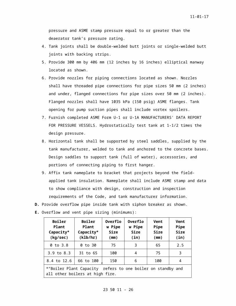
pressure and ASME stamp pressure equal to or greater than the
deaerator tank’s pressure rating.
4. Tank joints shall be double-welded butt joints or single-welded butt
joints with backing strips.
5. Provide 300 mm by 406 mm (12 inches by 16 inches) elliptical manway
located as shown.
6. Provide nozzles for piping connections located as shown. Nozzles
shall have threaded pipe connections for pipe sizes 50 mm (2 inches)
and under, flanged connections for pipe sizes over 50 mm (2 inches).
Flanged nozzles shall have 1035 kPa (150 psig) ASME flanges. Tank
opening for pump suction pipes shall include vortex spoilers.
7. Furnish completed ASME Form U-1 or U-1A MANUFACTURERS' DATA REPORT
FOR PRESSURE VESSELS. Hydrostatically test tank at 1-1/2 times the
design pressure.
23 50 11 - 21

11-01-17
8. Horizontal tank shall be supported by steel saddles, supplied by the
tank manufacturer, welded to tank and anchored to the concrete bases.
Design saddles to support tank (full of water), accessories, and
portions of connecting piping to first hanger.
9. Affix tank nameplate to bracket that projects beyond the field-
applied tank insulation. Nameplate shall include ASME stamp and data
to show compliance with design, construction and inspection
requirements of the Code, and tank manufacturer information.
D. Provide overflow pipe inside tank with siphon breaker as shown.
E. Overflow and vent pipe sizing (minimums):
Boiler Plant
Capacity* (kg/sec)
Boiler Plant
Capacity* (klb/hr)
Overflow Pipe Size (mm)
Overflow Pipe Size (in)
Vent Pipe Size (mm)
Vent Pipe Size (in)
0 to 3.8 0 to 30 75 3 65 2.5
3.9 to 8.3 31 to 65 100 4 75 3
8.4 to 12.6 66 to 100 150 6 100 4
*“Boiler Plant Capacity” refers to one boiler on standby and all other boilers at high fire.
SPEC WRITER NOTE: Delete heat exchanger if not required on this project.
F. //Continuous Blowoff Heat Exchangers:
1. Type: U-tube bundle, no shell, liquid-to-liquid, located below lowest
make-up water line of condensate storage tank.
2. Service: Receives water at boiler temperature and pressure in tubes,
water at condensate storage tank temperature 15 to 93 degrees C (59
to 199 degrees F) outside of tubes.
3. Heating Surface: Refer to drawings.
4. Construction: Hard-drawn seamless copper U-tubes with cast iron or
steel head bolted to mating flange which is welded to head of
condensate storage tank. Design for 1380 kPa (200 psig), 182 degrees
C (360 degrees F).//
G. Cleaning and Painting: Remove all foreign material to bare metal from
interior and exterior of tank. In preparation for interior coating,
sandblast interior to white metal in accordance with SSPC SP 5. Coat
exterior of tank with rust-resisting primer. Refer to Section 09 91 00,
PAINTING.
23 50 11 - 22

11-01-17
H. Interior Coating: Coat entire interior surface, including nozzles, with
water-resistant epoxy polymerized with amine adduct-type curing agent.
Coating shall be suitable for continuous service at 100 degrees C (212
degrees F) immersed in demineralized water and exposed to steam vapor.
Surface preparation, application of coating, number of coats, and curing
shall comply with printed instructions of coating manufacturer.
Ingredients of coating shall comply with U.S. Food and Drug Regulations
as listed under Title 21, Chapter 1, Part 175.300. Coating shall be
smooth, even thickness, with no voids. Holiday test at low voltage with
wet sponge method and repair all holidays.
I. Insulation: Field apply insulation as specified in Section 23 07 11,
HVAC AND BOILER PLANT INSULATION.
J. Water Level Indicators:
SPEC WRITER NOTE: Choose the type of water level indicator.
1. //Gauge Glasses: Red line type, overlapping glasses if multiple
glasses are utilized. Provide automatic offset-type gauge valves that
stop the flow if a glass is broken. Drain cock on lower gauge valve.
Gauge glass protecting rods.//
2. //Magnetic Float-Flag Type Water Level Gauge:
a. Tubular level gauge with internal float using concentric magnet
with stiffening rings. Float sequentially actuates magnetic flags
to indicate water level. Flags anodized black on one side, gold on
the other, with internal magnet.
b. Flags magnetically interlocked with mechanical stops to allow only
180-degree rotation.
c. Standpipe to be Schedule 40, Type 304 stainless steel.
d. Process connections 1035 kPa (150 psig) weld neck flanges.
Connections side type for maximum visibility.
e. Bottom connection 100 mm (4 inch) flange with drain plug.
Clearance between floor and bottom flange sufficient for removal
of float.
f. Switches for signals to be SPDT, 5-amp rating.//
3. Vertical pipe type header shall be connected to top and bottom of
storage tank with tank isolation valves and valved header drain.
Viewable gauges shall cover entire diameter of tank.
4. Minimum rating 121 degrees C, 200 kPa (250 degrees F, 29 psig).
23 50 11 - 23

11-01-17
K. High and Low-Level Alarm Switches:
1. Low Level Alarm Switch: Integral unit consisting of float, float
housing, hermetically sealed mercury switch. Locate external to tank
on a vertical header with valved tank connections and valved drain.
Switch elevation shall be 150 mm (6 inches) below the soft water make
up level.
2. High Level Alarm Switch: Integral unit consisting of conductivity
probes, probe housing. Float type not acceptable. Locate external to
tank on a vertical header, along with the low-level switch, with
valved tank connections and valved drain. High level alarm indication
shall occur 100 mm (4 inches) below the overflow level. Probes shall
be ac, not dc, stainless steel with virgin Teflon insulation.
3. Provide signals to //annunciator system// //computer workstation//
specified in Section 23 09 11, INSTRUMENTATION AND CONTROL FOR BOILER
PLANT.
4. All devices exposed to tank service conditions, including sensing
devices and transmitters shall be rated for 121 degrees C, 200 kPa
(250 degrees F, 29 psig) minimum.
L. Automatic Water Level Controls:
1. Separate electric or electronic type modulating water inlet flow
control valves for normal soft water make-up and for emergency city
water makeup. Actuated by electronic controller with input signals
from water level transmitter. Manual/auto control capability.
2. Performance: Maintain a minimum water level, plus or minus 25 mm (1
inch), in the tank by controlling the flow of soft water to the tank.
Soft water makeup shall be activated if water level falls to 30
percent of tank diameter plus 300 mm (12 inches). If water level
falls to 30 percent of tank diameter, automatically operate the
emergency city water makeup valve to bring the water level up 150 mm
(6 inches).
3. Water Level Transmitter: Programmable electronics, sealed diaphragms,
direct sensing electronics, no mechanical force or torque transfer
devices, external span and zero adjustment.
4. Controller: Proportional plus reset control, adjustable proportional
band, reset rate and level set points. Provide manual-automatic
control station on main instrument panel. Control station shall
indicate actual water level, soft water and emergency city water
level set points and valve positions. Provide same indicating and
23 50 11 - 24

11-01-17
control features on computer workstation specified in Section 23 09
11, INSTRUMENTATION AND CONTROL FOR BOILER PLANT. If new boiler
combustion controls are furnished as part of this contract, the water
level controller and transmitter shall be the same makes and models
as furnished for the combustion controls.
5. Water Flow Control Valves:
a. Globe style, bronze or cast-iron bodies, threaded ends for pipe
sizes 50 mm (2 inches) and under rated at 1725 kPa (250 psig),
ASME flanged ends for pipe sizes over 50 mm (2 inches) rated at
850 kPa (123 psig) or 1035 kPa (150 psig).
b. Replaceable Type 316 stainless steel plugs and seats. RTFE seal
for bubble-tight shut off. Linear flow characteristics.
c. Flow pressure loss 35 kPa (5 psig) maximum at maximum flow rating.
Unless otherwise shown, maximum flow rate shall be equivalent to
50 percent make-up rate with plant at maximum load (2 boilers at
high fire).
d. Electric or electronic type actuator that accepts input of 4-20 mA
or 2-10 VDC signal from controller.
e. Electronic positioner with 4–20 mA dc control output feedback.
Mounted integral with actuator. Digital positioner with capability
to self-calibrate. Maintenance diagnostic data retained in memory.
Design for 121 degrees C (250 degrees F) continuous service.
f. For valve actuators, comply with Section 23 09 11, INSTRUMENTATION
AND CONTROL FOR BOILER PLANT and Section 23 09 23, DIRECT-DIGITAL
CONTROL SYSTEM FOR HVAC.
2.3 BOILER BLOWOFF TANK AND ACCESSORIESA. Type: Cylindrical welded steel tank mounted vertically. Tank shall
include accessory equipment and shall be suitable for rigging into the
available space. Overall dimensions and arrangement of the tank and
accessories shall conform to the drawings. Tank volume shall be twice
the volume of a 100 mm (4 inch) blowoff (reduction in boiler water
level) from the largest boiler connected to the tank.
B. Service: Suitable for receiving, venting, storing, cooling and
discharging into the drain the effluent from the boilers resulting from
the intermittent operation of the boiler bottom blowoffs, boiler
accessory drains, and the use of continuous blowdowns.
23 50 11 - 25
11-01-17
C. Construction:
1. Construct tank and appurtenances in accordance with ASME BPVC Section
VIII. Tank shall have cylindrical shell and dished heads.
2. Material of construction shall be carbon steel ASTM A285/A285M, ASTM
A414/A414M, ASTM A515/A515M or ASTM A516/A516M.
3. Design tank for 275 kPa (40 psig) working pressure; the minimum
material thickness shall be 10 mm (3/8 inch). Thickness of head
material at any point shall not vary more than 10 percent from the
nominal thickness.
4. All tank joints shall be double-welded butt joints or single-welded
butt joints with backing strips.
5. Provide 300 mm by 406 mm (12 inches by 16 inches) elliptical manhole
located at the vertical centerline of the tank.
6. Provide 10 mm (3/8 inch) thick carbon steel wear plate welded to
interior of tank adjacent to tangential blowoff inlet as shown.
7. Provide nozzles for piping connections and provide tangential blowoff
inlet located above the normal water level. Tangential pipe for
blowoff inlet shall be Schedule 80, ASTM A53/A53M or ASTM A106/A106M,
seamless steel pipe with beveled end for field-welding of blowoff
from boilers. All other nozzles shall have threaded pipe connections
for pipe sizes 50 mm (2 inches) and under, 1035 kPa (150 psig) ASME
flanged connections for pipe sizes over 50 mm (2 inches). Nozzle
sizes listed below are based on National Board of Boiler and Pressure
Vessel Inspectors recommendations.
Pipe Connection Sizes, mm (inches)
Boiler Blowoff Water Outlet Vent
25 (1) 25 (1) 65 (2.5)
32 (1.25) 32 (1.25) 75 (3)
40 (1.5) 40 (1.5) 100 (4)
50 (2) 50 (2) 125 (5)
65 (2.5) 65 (2.5) 150 (6)
8. Furnish completed ASME Form U-1 or U-1A MANUFACTURERS' DATA REPORT
FOR PRESSURE VESSELS. Hydrostatically test tank at 1.3 times the
design pressure.
9. Tank nameplate shall be affixed to bracket which projects beyond the
tank insulation that will be applied in the field. Apply ASME data
23 50 11 - 26

11-01-17
stamp to nameplate to show compliance with design, construction and
inspection requirements of the Code.
10. Support tank by steel legs welded to shell of tank. Design saddles
or legs to support tank (full of water), accessories, and portions of
connecting piping to first hanger.
D. Cleaning and Painting: Remove all dirt, heavy rust, mill scale, oil,
welding debris from interior and exterior of tank. Prime exterior of
tank with rust-resisting paint. Refer to Section 09 91 00, PAINTING.
E. Insulation: Field apply insulation as specified in Section 23 07 11,
HVAC AND BOILER PLANT INSULATION.
F. Accessories:
1. Install red line type gauge glasses with protecting rods. Provide off
set type gauge valves with ball-check feature to automatically
prevent flow when glass is broken. Provide drain cock on lower gauge
valve. Glass shall be at least 300 mm (12 inches) long and centered
at the overflow level.
2. Provide thermometer and pressure gauge. Conform to Section 23 09 11,
INSTRUMENTATION AND CONTROL FOR BOILER PLANT.
3. Water Outlet Temperature Control Valve:
a. Type: Self-contained, reverse-acting thermal bulb-operated water
flow control valve.
b. Performance: Control valve shall operate automatically to control
blowoff tank water outlet temperature to 60 degrees C (140 degrees
F) maximum by regulating the flow of cold water which mixes with
the blowoff water and reduces the temperature of the blow-off
water. Provide valve designed for modulating and tight shut-off
service. Valve flow rates and pressure drops shall be as shown.
Temperature control range shall be adjustable, 38 to 77 degrees C
(100 to 170 degrees F) minimum.
c. Service: Provide valve designed to control the flow of city water
with temperature 4 to 27 degrees C (40 to 80 degrees F), and
pressure up to 690 kPa (100 psig). Thermal bulb will be inserted
in blowoff tank outlet pipe and will be subjected to water
temperatures up to 100 degrees C (212 degrees F).
d. Construction: Cast iron or bronze valve body designed for 850 kPa
(123 psig) minimum WOG. Design of valve shall permit access to
internal valve parts. Thermal bulb shall be separable socket type
with well.
23 50 11 - 27

11-01-17
4. Provide blowoff water outlet pipe inside tank as shown to provide a
water seal. Locate a 20 mm (3/4 inch) hole in top of this pipe inside
tank to act as siphon breaker.
SPEC WRITER NOTE: Utilize Para. 2.4, 2.5 or 2.6 for condensate transfer pumps depending on type of pump selected by the engineer.
2.4 CENTRIFUGAL MULTI-STAGE BOILER FEEDWATER PUMPS/CONDENSATE TRANSFER PUMPSA. Type: Two or more stages, centrifugal diffuser type, direct-coupled,
vertical shaft, in-line, base-mounted, motor-driven, arranged as shown.
B. Service: Design pumps and accessories for continuous service, 115
degrees C (240 degrees F) water, with flow rates ranging from maximum
scheduled on the drawings (plus manufacturer's recommended
recirculation) to 10 percent of maximum (plus manufacturer's recommended
recirculation). Pumps shall be suitable for parallel operation without
surging or hunting.
C. Performance: Refer to schedules on drawings. Pump head-flow performance
curve shall slope continuously upward to shut-off.
D. Control – Boiler Feed: Flow rates will be controlled by automatic
modulating feedwater valves on each boiler. Pumps shall be started and
stopped manually. Pumps //shall be constant speed// //shall have
variable frequency drives// controlled by boiler feed header pressure
electronic control system which must be provided. Control the header
pressure at // // kPa (// // psig). //For further information and
requirements refer to Section 26 29 11, MOTOR CONTROLLERS.//
E. Control - Condensate Transfer: Constant speed operation. Flow rate will
be controlled by automatic modulating water level control valve on
condensate transfer inlet to deaerator.
F. Construction:
1. Rotating elements shall be designed and balanced to conform to sound
and vibration limits specified in Section 23 05 51, NOISE AND
VIBRATION CONTROL FOR BOILER PLANT.
2. Mechanical seals shall have sealing face materials of carbon and
tungsten or silicon carbide.
3. Design bearings for two-year minimum life with continuous operation
at maximum pump operating load. Bearings and shaft seals shall be
water-cooled if recommended by pump manufacturer for the service.
4. Materials of Construction:
a. Chambers: Stainless steel
23 50 11 - 28

11-01-17
b. Impellers: Stainless steel
c. Diffusers: Stainless steel
d. Shaft: Stainless steel
e. Suction-Discharge Chamber: Cast iron or stainless steel
G. Recirculation Orifice: Provide stainless steel recirculation orifice
selected by pump manufacturer to protect pump from overheating at shut-
off and designed for low noise under the service conditions. Orifices
must not exceed sound level limits in Section 23 05 51, NOISE AND
VIBRATION CONTROL FOR BOILER PLANT.
H. Spare Parts: Provide complete rotating assembly for each pump size and
type suitable for field installation by plant personnel. Assembly shall
include impellers, diffusers, chambers, shaft, seals, and bearings.
I. Shaft Couplings: Pump manufacturer’s standard. Provide coupling guard.
J. Electric Motors: High efficiency type, open drip proof. Select motor
size so that the motor is not overloaded at any point on the pump head-
flow performance curve. Design motor for 40 degrees C (104 degrees F)
ambient temperature. For efficiency and power factor requirements refer
to Section 23 05 10, COMMON WORK RESULTS FOR BOILER PLANT AND STEAM
GENERATION.
K. Interface with Computer Workstation: Provide devices to signal computer
work station that motor is on or off.
2.5 CONDENSATE TRANSFER PUMPS, FLEXIBLE-COUPLED, END SUCTION, CENTRIFUGALA. Type: Single stage, end suction, centrifugal with volute casing,
horizontal shaft, frame-mounted, flexible-coupled, driven by constant
speed motor, arranged as shown. Pump frames and motors shall be base-
mounted.
B. Service: Design pumps and accessories for continuous condensate transfer
service, 93 degrees C (199 degrees F) water, with flow rates ranging
from maximum shown on drawings (plus manufacturer's recommended
recirculation) to 10 percent of maximum, (plus manufacturer's
recommended recirculation). Pumps shall be suitable for parallel
operation without surging or hunting.
C. Performance: Refer to schedules on drawings. Pump head-flow
characteristic curve shall slope continuously upward to shutoff.
D. Pump Size: Shall be such that a minimum of 10 percent increase in head
can be obtained at the maximum required flow rate by installing larger
impellers.
23 50 11 - 29

11-01-17
E. Construction:
1. Bolt pump casing to a frame that supports the pump shaft and shaft
bearings. Casing shall have back pull-out feature or bolted front
suction cover to allow access to impeller.
2. Frame which supports shaft and bearings shall provide easy access to
seal.
3. Rotating elements shall be designed and balanced so that vibration is
limited to requirements of Section 23 05 51, NOISE AND VIBRATION
CONTROL FOR BOILER PLANT.
4. Provide mechanical seal. Seal shall be exposed only to pump suction
pressure.
5. Provide replaceable shaft sleeve, water slinger on shaft, vent cock
and drain on casing. Provide casing wearing rings at all locations of
tight clearance between casing and impeller.
6. Bearings: Rated for two year minimum life with continuous operation
at maximum pump load.
7. Materials of Construction:
a. Casing: Cast iron
b. Impeller: Bronze
c. Shaft: Carbon steel
d. Shaft Sleeve: Bronze
e. Casing Wear Rings: Bronze
F. Recirculation Orifice: Provide stainless steel recirculation orifice
selected by pump manufacturer to protect pump from overheating at
shutoff. Refer to Section 23 05 51, NOISE AND VIBRATION CONTROL FOR
BOILER PLANT for sound level limitations.
G. Spare Parts: Provide sufficient types and quantities to allow complete
replacement of all such parts in one pump at one time:
1. Casing wear rings
2. Shaft sleeve
3. Pump bearings
4. Mechanical seal
H. Shaft Couplings: Shall be all metal, grid-type, flexible design which
permits parallel, angular, and axial misalignment. Coupling shall be
sufficiently flexible to reduce transmission of shock loads
significantly. Coupling size selection shall be based on coupling
manufacturer's recommendations for the service. Coupling shall include
no spacers made from organic material.
23 50 11 - 30

11-01-17
1. Pumps having back pull-out disassembly feature shall be provided with
spacer couplings designed to allow disassembly of pump without moving
the motor.
2. Provide coupling guard bolted to base plate.
I. Electric Motors: High efficiency, open drip proof designed for the
service. Select motor size so that the motor is not overloaded at any
point on the pump head-flow performance curve. Design motor for 40
degrees C (104 degrees F) ambient temperature. For efficiency and power
factor requirements, refer to Section 23 05 10, COMMON WORK RESULTS FOR
BOILER PLANT AND STEAM GENERATION.
J. Mounting: Mount pumps and motors on steel or cast-iron base plates with
drip-catching configuration. Align pumps and motor in the factory.
K. Sound and Vibration: Each pump and motor assembly shall conform to sound
and vibration limits specified in Section 23 05 51, NOISE AND VIBRATION
CONTROL FOR BOILER PLANT.
L. Interface with Computer Workstation: Provide devices to signal computer
workstation that motor is on or off.
2.6 CONDENSATE TRANSFER PUMPS, CLOSE-COUPLED, END SUCTION, CENTRIFUGALA. Type: Single stage, end suction, centrifugal with volute casing,
horizontal shaft, close-coupled with impeller mounted on motor shaft,
motor driven, and constant speed, arranged as shown.
B. Service: Design pumps and accessories for continuous condensate transfer
service, 93 degrees C (199 degrees F) water, with flow rates ranging
from maximum scheduled on drawings (plus manufacturer's recommended
recirculation) to 10 percent of maximum (plus manufacturer's recommended
recirculation). Pumps shall be suitable for parallel operation without
surging or hunting.
C. Performance: Refer to schedules on the drawings. Pump head-flow
performance curve shall slope continuously upward to shutoff.
D. Pump Size: Shall be such that a minimum of 10 percent increase in head
can be obtained at the maximum required flow rate by installing larger
impellers.
E. Construction:
1. Mount pump casing on a frame attached to the motor housing. Casing
shall have back pull-out feature or bolted front suction cover to
allow access to impeller.
2. Frame on which pump is mounted shall provide easy access to seal.
23 50 11 - 31

11-01-17
3. Rotating elements shall be designed and balanced so that vibration is
limited to requirements of Section 23 05 51, NOISE AND VIBRATION
CONTROL FOR BOILER PLANT.
4. Provide mechanical seals. Seal shall be exposed to pump suction
pressure only.
5. Provide replaceable shaft sleeve, water slinger on shaft, vent cock
and drain on casing. Provide casing wearing rings at all locations of
tight clearances between casing and impeller.
6. Bearings: Rated for two year minimum life with continuous operation
at maximum pump load.
7. Materials of Construction:
a. Casing: Cast iron
b. Impeller: Bronze
c. Shaft: Carbon steel
d. Shaft Sleeve: Bronze
e. Casing Wear Rings: Bronze
F. Recirculation Orifice: Provide stainless steel recirculation orifice
selected by pump manufacturer to protect pump from over-heating at
shutoff. Refer to Section 23 05 51, NOISE AND VIBRATION CONTROL FOR
BOILER PLANT for sound level limitations.
G. Spare Parts: Provide sufficient types and quantities to allow complete
replacement of all such parts in one pump at one time:
1. Casing wearing rings
2. Shaft sleeve
3. Motor bearings
4. Mechanical seal
H. Electric Motors: Joint NEMA-Hydraulic Institute Design Type JM or JP
approved motors, high efficiency, open drip proof, designed specifically
as close-coupled pump motors. Motor bearings shall be grease-lubricated
designed to carry all radial and thrust loads of the pump and motor
assemblies. Select motor size so that the motors are not overloaded at
any point on the pump head-flow performance curve. Design motors for 40
degrees C (104 degrees F) ambient temperature. For efficiency and power
factor requirements, refer to Section 23 05 10, COMMON WORK RESULTS FOR
BOILER PLANT AND STEAM GENERATION.
I. Sound and Vibration: Each pump and motor assembly shall conform to sound
and vibration limits specified in Section 23 05 51, NOISE AND VIBRATION
CONTROL FOR BOILER PLANT.
23 50 11 - 32

11-01-17
J. Interface with Computer Workstation: Provide devices to signal computer
workstation that motor is on or off.
2.7 CONDENSATE RETURN PUMP UNITS (ELECTRIC, PAD-MOUNTED)A. Type: Factory-assembled units consisting of vented horizontal pad-
mounted receiver tank, simplex or duplex motor-driven pumps as shown,
interconnecting piping, motor controls, and accessories. Arrangement of
pumps, tank and accessories shall be as shown or specified.
B. Service: Unit shall be designed to receive, store, and pump steam
condensate having temperature as shown. Pumps and motors shall be
suitable for continuous service.
C. Performance: Refer to schedules on the drawings.
D. Pumps: Centrifugal or turbine-type as shown.
1. Centrifugal Pumps: Bronze-fitted, vertical shafts, with mechanical
shaft seals. Stainless steel or alloy steel shafts with bronze shaft
sleeves. Pump shall be designed to allow removal of rotating elements
without disturbing connecting piping or pump casing mounting.
Bearings shall be grease-lubricated ball or roller type. Provide
casing wearing rings.
2. Turbine-type Pumps: Shall be split-case, base-mounted, flexible-
coupled, horizontal shaft, bronze fitted, with mechanical shaft
seals. Pumps shall be designed to allow removal of rotating elements
without disturbing connecting piping. Bearings shall be grease-
lubricated ball or roller type. Provide replaceable channel rings to
protect casing from wear. Shaft coupling shall be flexible type,
designed for the service. Provide coupling guard bolted to base
plate. Provide relief valves on pump discharge lines ahead of gate
valves. Set at 690 kPa (100 psig). Pipe relief vents to receiver
tank. Valve capacity shall equal or exceed pump capacity at set
pressure.
E. Electric Motors: Open drip proof. Select motor sizes so that the motors
are not overloaded at any point on the pump head-flow performance curve.
Motor shall be designed for 40 degrees C (104 degrees F) ambient
temperature.
F. Receiver Tank: Cast iron or galvanized steel, with storage capacity and
height of inlet connection as shown. Provide threaded or flanged
openings for all pipe connections and facilities for mounting float
switches. Openings for pipe sizes above 50 mm (2 inch) must be flanged.
23 50 11 - 33

11-01-17
Receivers for simplex pumps shall include all facilities required for
future mounting of additional pump and controls.
G. Controls:
1. Pump Operation: Provide float switches mounted on receiver tank to
start and stop water pumps in response to changes in the water level
in the receiver. Float switches shall be adjustable to permit the
controlled water levels to be changed. Floats and connecting rods
shall be copper, stainless steel or bronze. When a duplex pump unit
is used, provide an alternator and a control to automatically start
the second pump, when the first pump fails in keeping the receiver
water level from rising.
2. Starters: Provide combination magnetic starters with fusible
disconnect switches or circuit breakers. Provide low voltage control
circuits (120-volt maximum).
3. Indicating Lights: Provide red light for each pump to show that the
pump is running, green lights to show power is on.
4. Manual Selector Switches: Provide "on-off-automatic" switch for each
pump.
5. Electrical Wiring: Shall be enclosed in liquid-tight flexible metal
conduit. Wiring shall be suitable for 93 degrees C (199 degrees F)
service.
6. Control Cabinet: NEMA 250, Type 4 or better, enclosing all controls,
with manual switches and indicating lights mounted on the outside of
the panel. Attach to pump set with rigid steel framework unless other
mounting is shown on the drawings.
H. Accessories Required:
1. Thermometer on receiver below minimum water level. Thermometer must
conform to requirements in Section 23 09 11, INSTRUMENTATION AND
CONTROL FOR BOILER PLANT.
2. Basket-type inlet strainer with bolted cover, designed for 275 kPa
(40 psig), 99 degrees C (210 degrees F). Provide basket with 3.2 mm
(1/8 inch) diameter perforations.
3. Water level gauge on receiver. Provide gauge cocks that automatically
stop the flow of water when the glass is broken. Provide gauge glass
protection rods, and drain on lower gauge cock.
I. Sound and Vibration: Pump units shall conform to sound and vibration
limits specified in Section 23 05 51, NOISE AND VIBRATION CONTROL FOR
BOILER PLANT.
23 50 11 - 34

11-01-17
2.8 CONDENSATE RETURN PUMP UNITS (ELECTRIC, SUMP-TYPE)A. Type: Factory-assembled units consisting of vertical, extended shaft,
submerged, simplex or duplex (as shown), motor-driven condensate pumps
mounted on a horizontal cover plate. Bolt cover plate to a vented
underground sump-type receiver. Cover plate shall be flush with the
floor. Motors shall be above the cover plate.
SPEC WRITER NOTE: Note temperature limitation of this type of pump.
B. Service: Design units to receive, store, and pump steam condensate
having temperatures of 82 degrees C (180 degrees F). Pumps and motors
shall be suitable for continuous service.
C. Performance: Refer to schedules on the drawings.
D. Pumps: Centrifugal or turbine-type, vertical extended shaft, bronze-
fitted, flexible-coupled, designed for submerged operation. Provide
regreaseable ball thrust shaft bearings located at least six inches
above the cover plate, bronze shaft bearings adjacent to the pump
designed for water lubrication, intermediate water-lubricated shaft
bearings where required by length of shaft. Shaft shall be stainless
steel. Provide mechanical shaft seal at cover plate with bronze packing
gland. Pump manufacturer shall terminate the pump discharge pipes above
the cover plate. Bolt pump-motor units to brackets that are bolted to
the cover plate. Removal of one pump shall not affect operation of
second pump in duplex units. When turbine-type pumps are furnished,
provide relief valves on pump discharge lines ahead of gate valves. Set
at 690 kPa (100 psig). Pipe relief vents to receiver tank. Relief valve
capacity shall equal or exceed pump capacity at set pressure.
E. Electric Motors: Open drip proof, standard hp base. Select motor size so
that the motors are not overloaded at any point on the pump head-flow
performance curve. Motor shall be designed for 40 degrees C (104 degrees
F) ambient temperature.
F. Receiver Tank: Drawings will show when an existing sump or receiver is
to be reused. Unless otherwise noted, a new receiver is required. New
receiver shall be vertical, cylindrical, cast iron sides and bottom,
designed for service underground or below the floor. Receiver capacity
and size shall be as shown. Locate inlet connection 225 mm (9 inches)
below the cover plate.
G. Receiver Cover Plate: Heavy gauge steel designed to support weight of
pumps, motors, and accessories with no deflection. Cover plate shall
23 50 11 - 35
11-01-17
include provisions for mounting of pumps, motors and accessories by
bolting and shall be designed to allow easy removal of same. Provide
threaded or flanged openings for piping connections. Openings for pipe
sizes above 50 mm (2 inches) must be flanged. Cover plate shall be
designed to fit new or existing receiver tank or sump as shown. Provide
bolted inspection plate for viewing interior of receiver. All bolted
connections to cover plate and between cover plate and receiver shall be
gasketed so that no vapor will escape into the room.
H. Controls:
1. Pump Operation: Provide float switches mounted on receiver cover
plate to start and stop the pumps in response to changes in the water
level in the receiver. Float rod penetrations of the receiver cover
plate shall be sealed to prevent the escape of vapor. Floats and
connecting rods shall be copper, stainless steel or bronze. When a
duplex pump unit is required, provide an alternator and a control to
automatically start the second pump, when the first pump fails in
keeping the receiver water level from rising.
2. Starters: Provide combination magnetic starters with fusible
disconnect switches or circuit breakers. Provide low voltage control
circuits (120-volt maximum).
3. Indicating Lights: Provide red light for each pump to show that the
pump is running, green lights to show power is on.
4. Manual Selector Switches: Provide "on-off-automatic" switch for each
pump.
5. Electrical Wiring: Enclose in liquid-tight flexible metal conduit.
Wiring shall be suitable for 93 degrees C (199 degrees F) service.
6. Control Cabinet: NEMA 250, Type 4 or better, enclosing all controls,
with manual switches and indicating lights mounted on the outside of
the panel. Provide rigid mounting to adjacent building wall or column
as shown on the drawings.
I. Sound and Vibration: Pump unit shall conform to sound and vibration
limits specified in Section 23 05 51, NOISE AND VIBRATION CONTROL FOR
BOILER PLANT.
SPEC WRITER NOTES:1. Be aware that this type of pump
requires gravity condensate flow to the receiver, which is located above the pump, and gravity condensate flow from the receiver into the pump. Because of
23 50 11 - 36

11-01-17
this, it may be necessary to locate the pump in a pit.
2. A failure mode of the float-valve mechanism allowing live steam to continuously flow into the condensate return system. Thermometer located on the pump outlet will indicate this problem.
2.9 MECHANICAL CONDENSATE PUMP (PRESSURE-POWERED CONDENSATE PUMP)A. Type: Packaged receiver and //simplex// //duplex// pump set including
all controls and interconnecting piping and valves. Pumps shall be
automatic, float-actuated, non-electric, steam motive power, designed to
pump required condensate flow rate and discharge pressure.
B. Service: Continuous duty, condensate at 100 degrees C (212 degrees F),
motive steam available at // // kPa (// // psig). //Design to
operate also with compressed air motive power at plant startup. This
would require a manual change over between steam and compressed air
piping connection. Only one pipe connection to the pump where either
steam or compressed air can be physically connected to so as to preclude
simultaneous use of both motive power sources.// Design to operate with
and to connect properly with the condensate return line elevation as
shown.
C. Performance: Refer to drawings for condensate flow and discharge
pressure requirements and for receiver size.
D. Pump Construction:
1. Pump Body: //Cast iron// //Fabricated steel// rated for 1035 kPa (150
psig), 232 degrees C (450 degrees F). Low profile as necessary to
accommodate the elevation of the inlet condensate pipe, obtain the
required filling head, and obtain the required performance.
2. Float mechanism: Stainless steel float and mechanism frame. Inconel
X-750 spring assist float mechanism.
3. Internal Pump Valves and Seats: Externally replaceable hardened
stainless steel.
4. Receiver Tank: ASME BPVC Section VIII designed for 850 kPa (123
psig). Refer to paragraph, FLASH TANK.
5. All piping shall be ASTM A53/A53M or ASTM A106/A106M, ERW or
seamless, Schedule 80.
23 50 11 - 37

11-01-17
E. Receiver Construction:
1. Cylindrical welded steel tank with accessories. Conform to ASME BPVC
Section VIII. Fabricate from steel sheets and plates or from steel
pipe and pipe caps.
2. Materials of Construction:
a. Steel sheets and plates: ASTM A285/A285M, ASTM A414/A414M, ASTM
A515/A515M, ASTM A516/A516M.
b. Steel pipe and pipe caps: Pipe ASTM A53/A53M A-S, A53/A53M A-E,
A53/A53M B-S, A53/A53M B-E. Pipe Caps ASTM A234/A234M, ASME B16.9.
3. Design for 850 kPa (123 psig), 178 degrees C (353 degrees F).
4. Piping Connections: Threaded half couplings for pipe sizes under 65
mm (2-1/2 inches). Flanged 1035 kPa (150 psig) ASME for pipe sizes
over 50 mm (2 inches).
5. ASME Forms: Furnish U-1 or U-1A, MANUFACTURERS' DATA REPORT FOR
PRESSURE VESSELS.
6. Supports: Unless shown otherwise, provide floor-mounted frame
constructed with steel angles.
7. Insulation: Do not insulate.
F. Cleaning and Painting: Remove all dirt, heavy rust, mill scale, oil,
welding debris from interior and exterior. Coat exterior with rust-
resisting primer and manufacturer’s standard coating.
G. Accessories:
1. Water level gauge glass on tank and pumps with protection rods, gauge
valves with drain.
2. All necessary inlet and outlet check valves for proper operation.
3. Industrial liquid-type thermometer on condensate outlet, dual range,
10 to 204 degrees C (50 to 400 degrees F), 225 mm (9 inch) scale
length, accuracy plus or minus one scale division.
4. Provide connections to plant compressed air supply complete with
shut-off valve, air pressure regulator, and pressure relief valve. If
plant compressed air supply is not available, the required air
compressor(s) shall be part of the submittal and considered part of
the pump equipment at no extra cost to the Government, including all
plumbing and electrical connections.
2.10 VACUUM HEATING PUMP UNITSA. Type: Factory-assembled units consisting of water storage and air
separating facilities, duplex water pumps, duplex air pumps (separate
from water pumps), motors, controls, and accessories. Units must be
23 50 11 - 38

11-01-17
suitable for the space available for rigging and placement and shall be
arranged as shown on the drawings.
B. Service: Design units to receive, store and pump the steam condensate
from a vacuum heating system. The units shall also produce the required
vacuum. Air and water pumps and motors shall be suitable for continuous
service.
C. Performance: Refer to schedules on the drawings. Base pump ratings on
condensate at 70 degrees C (158 degrees F) and 19 kPa (5-1/2 inches Hg)
vacuum.
D. Water and Air Pumps: Centrifugal type, bronze-fitted, vertical shafts,
with mechanical shaft seals. Shafts shall be stainless steel. Design
pumps to allow removal of rotating elements without disturbing
connecting piping or pump casing mounting. Bearings shall be grease-
lubricated ball or roller-type. Provide casing wearing rings.
E. Receiver Tank: Cast iron or galvanized steel with water storage and air
separation chambers. Water storage capacity and inlet height shall be as
shown. Provide threaded pipe connections for sizes 50 mm (2 inches) and
smaller, flanged connections for pipe sizes above 50 mm (2 inches).
F. Electric Motors: Open drip proof. Select motor sizes so that the motors
are not overloaded at any point on the pump characteristic curve. Motors
shall be designed for 40 degrees C (104 degrees F) ambient temperature.
G. Motor Controls:
1. Air and Water Pump Operation: Provide float switches mounted on
receiver tank to start and stop water pumps in response to changes in
the water level in the receiver. Float switches shall be adjustable
to permit the controlled water level to be changed. Floats and
connecting rods shall be copper, stainless steel, or bronze. Provide
adjustable vacuum switches mounted on receiver tank to start and stop
air pumps in response to vacuum requirements of the heating system.
Air and water pump controls shall include alternators and also
controls to automatically start the second air or water pump when the
first pump fails to meet the air or water demand.
2. Starters: Provide combination magnetic starters with fusible
disconnect switches or circuit breakers. Provide low voltage control
circuits (120-volt maximum).
3. Indicating Lights: Provide red lights for each pump to show that the
pump is running, green lights to show power is on.
23 50 11 - 39

11-01-17
4. Manual Selector Switches: Provide "on-off-automatic" switch for each
pump.
5. Electrical Wiring: Shall be enclosed in liquid-tight flexible metal
conduit. Wiring shall be suitable for 93 degrees C (199 degrees F)
service.
6. Control Cabinet: NEMA 250, Type 4 or better, enclosing all controls,
with manual switches and indicating lights mounted on the outside of
the panel. Attach to pump set with rigid steel framework unless other
mounting is shown on the drawings.
H. Accessories Required:
1. Thermometer on receiver below minimum water level. Thermometer shall
conform to requirements in Section 23 05 51, NOISE AND VIBRATION
CONTROL FOR BOILER PLANT.
2. Basket-type inlet strainer with bolted cover, designed for 275 kPa
(40 psig), 100 degrees C (212 degrees F). Provide basket with 3.2 mm
(1/8 inch) diameter perforations.
3. Water level gauge on each compartment of receiver. Provide gauge
cocks which automatically stop the flow of water when the glass is
broken. Provide gauge glass protection rods and drain on lower gauge
cock.
4. Compound pressure/vacuum gauge which shall conform to requirements in
Section 23 09 11, INSTRUMENTATION AND CONTROL FOR BOILER PLANT.
5. Temperature limit switch to automatically admit cooling water to the
air separation chamber when the air separation water temperature
exceeds the recommended limit.
6. Automatic water make-up to the air separation chamber consisting of
float switch and solenoid valve. Provide manual bypass valve.
7. When air vent produces a sound exceeding 85 dB(A) at a distance of
1800 mm (6 feet) from the unit, provide a silencer to reduce the
sound to 85 dB(A) maximum. Silencer shall be as recommended by pump
manufacturer for the service.
8. Provide 15 mm (1/2 inch) valved drains from condensate receiver and
air separation chamber to nearest floor drain.
9. Provide adjustable vacuum breaker to protect pump unit from excessive
vacuum. Minimum adjustment range shall be 17 to 51 kPa (5 to 15
inches Hg).
23 50 11 - 40

11-01-17
I. Sound and Vibration: Pump units shall conform to sound and vibration
limits specified in Section 23 05 51, NOISE AND VIBRATION CONTROL FOR
BOILER PLANT.
2.11 FLASH TANKA. Type: Cylindrical welded steel tank with accessories as shown. Refer to
detail on drawings.
B. Service: Suitable for receiving, venting, storing and discharging to
condensate return pump the effluent discharged from steam traps on high
and medium pressure steam systems.
C. Construction:
1. Conform to ASME BPVC Section VIII. Fabricate from steel sheets and
plates or from steel pipe and pipe caps.
2. Materials of Construction:
a. Steel sheets and plates: ASTM A285/A285M, ASTM A414/A414M, ASTM
A515/A515M, ASTM A516/A516M.
b. Steel pipe and pipe caps: Pipe ASTM A53/A53M A-S, A53/A53M A-E,
A53/A53M B-S, A53/A53M B-E. Pipe Caps ASTM A234/A234M, ASME B16.9.
3. Design tank for 850 kPa (123 psig), 178 degrees C (353 degrees F).
4. Piping Connections: Threaded half couplings for pipe sizes under 65
mm (2-1/2 inches). Flanged 1035 kPa (150 psig) ASME for pipe sizes
over 50 mm (2 inches).
5. ASME Forms: Furnish U-1 or U-1A, MANUFACTURERS' DATA REPORT FOR
PRESSURE VESSELS.
6. Supports: Unless shown otherwise, provide floor-mounted frame
constructed with steel angles.
7. Condensate Pipe: Provide perforated Schedule 80 steel pipe inside
tank as shown.
D. Cleaning and Painting: Remove all dirt, heavy rust, mill scale, oil,
welding debris from interior and exterior of tank. Coat exterior with
rust-resisting primer. Refer to Section 09 91 00, PAINTING.
SPEC WRITER NOTE: Insulate flash tank if flash steam is recovered and utilized.
E. Insulation: //Do not insulate.// //Insulate per Section 23 07 11, HVAC
AND BOILER PLANT INSULATION.//
2.12 FUEL OIL PUMPING EQUIPMENT (BURNER FUEL)A. //Pump and Motors (for above flood plain installation):
23 50 11 - 41

11-01-17
1. Type: Constant displacement, rotary, three-screw-type, horizontal
shaft, flexible-coupled, motor-driven, base-mounted, arranged as
shown.
2. Service: Pumps, motors and accessories shall be designed for
continuous fuel oil service as shown on the drawings.
3. Performance: Refer to schedules on the drawings. Vendor shall submit
complete data to certify that pumps offered will perform in
accordance with requirements for suction lift, discharge pressure,
sound level limitations and flow rate at viscosity range shown.
4. Pump Construction:
a. Pump Casing: Cast iron or steel designed for 1035 kPa (150 psig)
minimum. Casing shall have removable bolted sections to allow
access to internal parts.
b. Power Rotor: Alloy steel.
c. Idler Rotors: Pearlitic Gray Iron.
d. Shaft Seals and Bearing: Provide mechanical seals and ball
bearings as recommended by pump manufacturer for the service.
e. Internal Relief Valves: Shall not be provided.
5. Electric Motors Drives: High efficiency, open drip proof. Select
motor sizes so that motors are not overloaded under all operating
conditions. Motors shall be designed for 40 degrees C (104 degrees F)
ambient temperature. For efficiency and power factor requirements,
refer to Section 23 05 10, COMMON WORK RESULTS FOR BOILER PLANT AND
STEAM GENERATION.
6. Mounting - Pumps and Motors: Mount on steel or cast-iron base plates.
Align pumps and motors at the factory.
7. Shaft Couplings: Shall be all metal, grid-type, flexible design that
permits parallel, angular, and axial misalignment. Coupling shall be
sufficiently flexible to reduce transmission of shock loads
significantly. Coupling size selection shall be based on
manufacturer's recommendation for service. Provide coupling guard
bolted to base plate.
8. Sound and Vibration: Each combination of pump and driver shall
conform to sound and vibration limits specified in Section 23 05 51,
NOISE AND VIBRATION CONTROL FOR BOILER PLANT.//
B. //Pump and Motors (for //below flood plain// //below grade//
installation): Oil pump and motor assembly shall be factory assembled in
an epoxy-enamel coated carbon steel waterproof enclosure with external
23 50 11 - 42

11-01-17
threaded connections for pump suction and discharge. The base-mounted
motor shall be directly connected by a flexible coupling to a bi-
rotational, internal gear pump, having self-adjusting mechanical seals
and cast-iron housing. The pump and motor assembly shall be mounted on a
sliding steel base for easy access. Stainless steel flex hoses shall
connect pump suction and discharge to couplings welded to the pump
enclosure. A discriminating leak detector shall be installed at the low
point of the pump enclosure to detect and annunciate the presence of oil
or water. Electrical connections shall include sealed conduit and wire
pigtails for termination above expected high water levels.//
C. Duplex Strainers: Provide duplex, basket-type cast iron strainers
designed to allow one basket to be removed for cleaning while the other
is in service. Strainer shall include diverter valve with handle that
will select the strainer to be in use. Operation of the diverter valve
shall not stop the flow of fluid. Basket covers shall be clamp-type.
Ratio of free straining area to area of strainer pipe size shall be at
least 4 to 1. Strainer baskets shall be brass or stainless steel.
Provide 60 mesh basket liners for No. 2 fuel oil. Strainers on suction
side of pumps shall be 345 kPa (50 psig), 93 degrees C (199 degrees F)
minimum design; discharge side 1380 kPa (200 psig), 93 degrees C (199
degrees F) minimum.
D. Pressure Relief Valves (Overpressure Protection): Provide at discharge
of each oil pump. Size valves to relieve the maximum pumping capability
of each oil pump furnished, 965 kPa (140 psig) set pressure of the
relief valves plus 25 percent accumulation. Pressure settings shall be
adjustable. Valves shall have solid ungrooved plug and shall close
bubble-tight.
E. Back Pressure Control Valve (Pump Pressure Control): Valve shall operate
to maintain an essentially constant pump discharge pressure as required
by the burners furnished, with a set pressure as scheduled on the
drawings. Pressure rise shall not exceed five percent of set pressure.
Flow range shall exceed the flow of the largest oil pump in the set. Set
pressure shall be adjustable plus or minus 20 percent of set pressure.
Valve shall have stainless steel disc and seat, bronze body. Valve disc
and seat shall be renewable. Valve shall be designed for fuel oil
service as shown on the drawings.
F. Gate Valves, Globe Valves, Pipe, Pipe Fittings, Pressure Gauges,
Thermometers, and Miscellaneous Piping Specialties: Refer to Section 23
23 50 11 - 43

11-01-17
21 11, BOILER PLANT PIPING SYSTEMS, and Section 23 09 11,
INSTRUMENTATION AND CONTROL FOR BOILER PLANT.
SPEC WRITER NOTE: Choose the type of pump arrangement from either paragraph G or H.
G. //Arrangement (Pump Set): Pumps, motors, valves, oil heaters, piping and
accessories shall be furnished as a factory-built unit. All items of
equipment shall be mounted on a steel drip pan base with an area
sufficient to extend beyond the limits of all equipment, constructed of
3.2 mm (1/8 inch) steel with 50 mm (2 inch) high vertical sides. Provide
threaded 15 mm (1/2 inch) plugged opening for draining. Arrange valves
and piping on rigid steel supports welded to the base. All items of
equipment shall be readily accessible for operation and maintenance.
Pump set shall be suitable for the space available for rigging and
placement. When oil heaters are required, they shall be part of the pump
set and located for easy access.//
H. //Arrangement (Pumps and Equipment Individually Mounted): Provide drip
pan for each pump, for the oil heaters, and for the duplex strainers.
Construct each drip pan of 3.2 mm (1/8 inch) thick steel with 50 mm (2
inch) high vertical sides. Provide threaded 15 mm (1/2 inch) plugged
openings for draining. Pumps, oil heaters and strainers shall be
suitable for the space available for rigging and placement.//
I. Spare Parts: Complete mechanical seal for one oil pump. Complete set of
casing gaskets for one oil pump. Back pressure control valve, complete.
J. Motor Controls: Provide devices to signal computer workstation that
motors are on or off.
2.13 FUEL OIL HEATERS AND ACCESSORIESA. Steam Heaters and Control Valves:
1. Heater Type: Shell and tube, horizontally mounted, oil-in-shell,
steam-in-tubes, designed for fuel oil preheating.
2. Performance: Shall be as shown on drawings.
3. Heater Construction:
a. Design unit for maximum steam pressure of 1035 kPa (150 psig) at
188 degrees C (370 degrees F) and maximum oil pressure of 1380 kPa
(200 psig) at 132 degrees C (270 degrees F).
b. Materials and fabrication shall be in accordance with the ASME
BPVC Section VIII.
23 50 11 - 44

11-01-17
c. Tubes shall be steel, rolled into tube sheets. Locate tube sheets
at one end of the heater only, no floating tube sheets permitted.
Tubes and tube sheets shall be easily removable from the shell.
d. Provide baffles in shell to provide cross-flow of oil to improve
heat transfer.
e. Provide flanged head for access to steam side and removal of
tubes.
f. Provide pipe connection nozzles for steam inlet and condensate
outlet, oil inlet and outlet, cleaning fluid inlet and outlet (in
shell-plugged), air vent (steam side-plugged), relief valve, drain
(plugged).
SPEC WRITER NOTE: Review fuel oil characteristics to determine if automatic viscosity control system should be provided in lieu of oil temperature control.
4. Temperature Control Valves: Designed to control oil outlet
temperature by regulating steam flow to the heater. Provide cast iron
or cast steel bodies designed for 1035 kPa (150 psig), 188 degrees C
(370 degrees F) steam, threaded ends for 50 mm (2 inch) pipe size and
under, 1035 kPa (150 psig) or 1725 kPa (250 psig) ASME flanged ends
for pipe sizes over 50 mm (2 inches). Valve seat and discs (plugs)
shall be hardened stainless steel or equivalent material. Valves
shall be pilot-controlled, diaphragm actuated. Pilot shall sense oil
temperature by means of a thermal bulb in the oil stream and provide
temperature adjustment range of 77 to 132 degrees C (170 to 270
degrees F). Valve shall automatically hold heated oil temperature
within plus or minus 1 degrees C (34 degrees F) of set point with oil
flow variation from 10 percent to 100 percent of maximum scheduled on
the drawings. Provide dial thermometer on the pilot.
B. Electric Heaters and Controls:
1. Heater Type: Shell-type with immersion-type electric resistance
heating elements, designed for fuel oil preheating.
2. Performance: Refer to schedules on the drawings.
3. Heater Construction:
a. Design unit for maximum oil pressure of 1375 kPa (200 psig) at 132
degrees C (270 degrees F).
b. Materials and fabrication of shell and heads shall be in
accordance with the ASME BPVC Section VIII.
23 50 11 - 45

11-01-17
c. Electrical elements shall be UL listed, designed for the
electrical service shown on the drawings. Elements shall be easily
removable from the heater shell.
d. Provide flanged head for access to heating elements.
e. Provide pipe connection nozzles for oil inlet and outlet, cleaning
fluid inlet and outlet (plugged), relief valve, drain (plugged).
f. Comply with UL 574.
SPEC WRITER NOTE: Review fuel oil characteristics to determine if automatic viscosity control system should be provided in lieu of oil temperature control.
4. Controls: Provide control cabinet located near heater. Cabinet shall
include fusible disconnect switches or circuit breakers, control
transformer (120 volt), contactors for heater power, indicating
lights for "heater on" (red) and "power on" (green). Control heater
power contactors by thermostat in oil line. Thermostat shall have
minimum adjustment range of 77 to 132 degrees C (170 to 270 degrees
F). Oil output temperature shall be automatically held within plus or
minus 1 degrees C (2 degrees F) of set point with oil flow variation
from 10 percent to 100 percent of maximum on the drawings.
C. Pipe, Valves, Fittings, Miscellaneous Piping Specialties, Pressure
Gauges and Thermometers: Refer to specification Section 23 21 11, BOILER
PLANT PIPING SYSTEMS, and Section 23 09 11, INSTRUMENTATION AND CONTROL
FOR BOILER PLANT.
D. Pressure Relief Valves: Provide on the shell of each oil heater. Size
valves to relieve maximum combined pumping capability of all oil pumps
at 965 kPa (140 psig) set pressure plus 25 percent accumulation.
Pressure settings shall be adjustable. Valves shall close tightly with
no leakage.
E. Arrangement: Heaters shall be mounted individually or as part of a pump
set as shown on the drawings. Locate heaters to allow easy access to all
valves and traps, and to allow complete removal of heating elements
without disturbing piping, equipment, or building walls. All items of
equipment shall be readily accessible.
F. Insulation: Required on the oil heaters, all hot oil pipelines, all
steam and condensate pipe lines. Refer to Section 23 07 11, HVAC AND
BOILER PLANT INSULATION.
23 50 11 - 46

11-01-17
2.14 NO. 2 FUEL OIL TEMPERATURE CONTROL SYSTEMA. General: Provide for each aboveground fuel oil tank system that stores
No. 2 fuel oil. Consisting of an oil pump, an electric oil heater,
controls, valves, and piping connected to the fuel oil tank supply and
return lines. The purpose is to maintain oil tank temperature of
approximately 0 degrees C (30 degrees F) to control the oil viscosity
and to keep the oil tank temperature above the pour point of the oil.
B. Oil Pump: Electric motor-driven, rotary gear-type, mechanical shaft
seal, hardened steel gears and shafts. Pump shall be close-coupled,
motor-mounted. Shaft couplings shall have no organic material. Pump
performance shall be as shown on the drawings.
C. Electric Oil Heater: Shell-type with immersion-type electric resistance
heating elements, designed for fuel oil heating. Design unit for maximum
oil pressure of 1375 kPa (200 psig). Materials and fabrication of shell
and heads shall be in accordance with the ASME BPVC Section VIII.
Heating elements shall have electrical ratings in accordance with
drawing requirements and shall be removable. Comply with UL 574. Provide
pipe connections shown.
D. Controls: Provide locally mounted control panel consisting of manual
start-stop controls for the oil pump, thermostatically controlled
contactors for the oil heater, red indicating lights for "pump running",
"heater on", and green for "power on". Also include in panel, fusible
disconnect switches or circuit breakers and control transformer (120
volt) for heater thermostat and indicating lights. Thermostat shall have
minimum adjustment range of -12 to 16 degrees C (10 to 61 degrees F).
Provide devices to signal computer workstation that system is on or off.
E. Pressure Relief Valves: Provide on the shell of the oil heater and on
the oil pump discharge line where shown. Valves shall be sized to
relieve the maximum combined pumping capability of all oil pumps, at 965
kPa (140 psig) set pressure plus 25 percent accumulation. Pressure
settings shall be adjustable. Route relief discharge pipe back to oil
tank.
F. Pipe, Valves, Fittings, Miscellaneous Piping Specialties, Pressure
Gauges and Thermometers: Refer to specification Section 23 21 11, BOILER
PLANT PIPING SYSTEMS, and Section 23 09 11, INSTRUMENTATION AND CONTROL
FOR BOILER PLANT.
G. Arrangement: Heaters, pumps, controls and interconnecting piping shall
be wall-mounted on reinforced sheet metal as shown on the drawings.
23 50 11 - 47
11-01-17
2.15 COMPRESSED AIR SYSTEMA. Provide complete compressed air system to serve oil burner cold start
atomization (steam-atomizing oil burners) and/or pressure powered
condensate pump motive air, to provide shop (cleaning and maintenance)
air, and to serve controls and instruments. Compressed air systems shall
include compressors, motor drives, receivers, aftercoolers, filters, air
dryers and accessories as scheduled, as shown on the drawings and as
specified. //A minimum of two compressors shall be supplied to allow for
maintenance and N+1 redundancy.//
B. Compressors:
1. Type: Reciprocating, two-stage, air-cooled, intercooled, V-belt
drive.
2. Performance: Shall be as shown on the drawings. Shall be suitable for
continuous service.
3. Construction:
a. Lubrication: Splash type with low oil level automatic shutdown
switch, or pressure type with low oil pressure automatic shutdown
switch.
b. Unloading: Provide automatic cylinder air pressure unloader to
prevent compressor starting under load.
c. Inlet Filter: Dry-type with replaceable cartridge.
d. Cylinders: Shall be removable from crankcase.
C. Receivers: Vertical or horizontal cylindrical tanks as shown on the
drawings. Construct in accordance with the ASME BPVC Section VIII with
inspection under the rules of the National Board of Boiler and Pressure
Vessel Inspectors. Design pressure 1035 kPa (150 psig) minimum.
D. Compressor and Receiver Accessories:
1. Water-cooled Aftercooler: Provide one for each compressor, designed
to cool the compressor output air to within 7 degrees C (10 degrees
F) of the cooling water temperature. Mount on or adjacent to
compressor. Provide cooling water solenoid control valve. Valve shall
automatically open when compressor starts and close when compressor
stops.
2. Automatic Condensate Traps: Provide on lowest point of receiver and
on aftercooler if required by type of aftercooler furnished. Size
shall be suitable for compressor air delivery.
23 50 11 - 48

11-01-17
3. Safety Valve: Provide on receiver, set pressure lower than receiver
design pressure. Capacity of valve at set pressure shall be greater
than maximum output of all compressors supplying receiver.
4. Pressure Gauges: Provide on receiver and as shown. Refer to
specification Section 23 09 11, INSTRUMENTATION AND CONTROL FOR
BOILER PLANT.
5. Receiver Piping Connections: Shall include air in, air out, safety
valve, automatic drain, valved manual drain and valved pressure
gauge.
E. Compressor Controls:
1. Compressor Serving Oil Burner Cold Start Atomization, Oil Tank
Gauges, and Flue Gas Oxygen Analyzers Only: Automatic start-stop
control actuated by pressure in receiver. Pressure settings shall be
adjustable.
2. Compressors Serving Boiler Plant Controls or Instruments: Dual
control enabling the manual selection of either automatic start-stop
control (actuated by adjustable receiver pressure switch), or
constant speed control in which the compressor runs constantly but
only compresses air between predetermined adjustable receiver
pressure limits.
3. Controls shall operate on 120 volts maximum. Provide "on-off-
automatic" control for each compressor.
F. Electrical Motors and V-Belt Drives: Motors shall be open drip proof
designed for 40 degrees C (104 degrees F) ambient temperature. Select V-
belt drives in accordance with manufacturer's recommendations for
frequent start-stop service. Provide belt guard that encloses belts on
all sides.
G. Vibration Isolation: Refer to specification Section 23 21 11, BOILER
PLANT PIPING SYSTEMS, for isolators required in piping.
H. //Refrigerated Air Dryer: Shall be refrigerant-type with capacity
sufficient for all pneumatic controls and instruments in the boiler
plant. Cycling type which turns on and off in response to load. Base
capacity ratings on 690 kPa (100 psig) inlet pressure; 38 degrees C (100
degrees F) air inlet temperature; 38 degrees C (100 degrees F) ambient
air temperature. Unit shall maintain dewpoint at 2 to 4 degrees C (35 to
40 degrees F) at 690 kPa (100 psig) air pressure. Provide unit with
"power on" light, automatic water drain trap. Provide reheat of output
23 50 11 - 49

11-01-17
air by heat exchange with input air to decrease condensation on air
pipes. Design unit for 1035 kPa (150 psig).//
I. //Desiccant Air Dryers: Shall be the heatless, or heated, or heated
blower, twin desiccant tower all in one factory pre-piped and pre-wired
package. When one tower is in regeneration mode the other tower will be
in drying mode. Package to include digital electronic multi-function
controller programmed to execute all valve switching functions, monitor
drying operations, MODBUS compatible, backlit LCD display, NEMA 4 or
better enclosure, remote alarm contact, sound attenuating purge muffler,
pre-filter, after-filters, stainless steel desiccant screen, high
strength desiccant, high temperature ball or butterfly valves with
stainless steel internals and, double acting pneumatic actuators.//
J. Air Filter: Located in compressed air line between receiver and air
dryer, coalescing type, designed to remove oil, entrained water mist,
and dirt from the compressed air. Provide automatic drain valve piped to
nearest drain. Size unit for maximum pressure drop of 3.5 kPa (0.5 psig)
at normal air flow rate. Design unit for 1035 kPa (150 psig) air
pressure.
K. Spare Parts:
1. Complete set of drive belts.
2. Two filter cartridges for each compressor intake filter.
3. Two filter cartridges for air dryer intake filter.
SPEC WRITER NOTE: The vent silencer is essential on steam exhaust lines that are utilized for creating loads on boilers for tune-ups and testing.
2.16 STEAM VENT SILENCER (MUFFLER)A. Type: Residential quality designed to attenuate low and high frequency
sound generated by steam vented through a globe valve from a high-
pressure header.
B. Service and Performance: Shall be capable of entire maximum steam output
of largest boiler in the plant with superheated steam flowing through
the silencer at 100 kPa (14.7 psig), 150 degrees C (302 degrees F).
Steam in header will be 99.0 to 99.5 percent quality. Venting through
globe valve to silencer will cause super-heating and pressure drop to
near atmospheric. Unit will be a permanent installation and will be
utilized to create steam loads to allow burner adjustments and boiler
tests. Pressure loss through unit shall be low. Required attenuation
23 50 11 - 50

11-01-17
listed below is the insertion loss. No credit is permitted for air
absorption at the outlet.
C. Minimum Attenuation:
1. 12 dB minimum at 63 Hz
2. 17 dB minimum at 125 – 250 Hz
3. 25 dB minimum at 250 – 500 Hz
4. 34 dB minimum at 500 – 8000 Hz
D. Construction: Construct unit of steel with glass fiber or metallic wool
acoustical packing. Protect glass fiber acoustical material from damage
in high fluid impact areas. Line entire outer shell internally with
acoustical material. Provide 1035 kPa (150 psig) ANSI inlet and outlet
flanges as shown on the drawings. Where flanges are not shown, provide
butt weld connections.
2.17 BOILER WATER AND DEAERATOR WATER SAMPLE COOLERSA. Type: Factory-built shell and coiled tube heat exchanger with sample in
tube, cooling water in shell, designed for wall mounting.
B. Construction:
1. Shell and Head: Iron, steel or stainless-steel shell, bolted or
threaded into head. Head shall have wall mounting brackets and piping
connections for sample in and out and cooling water out. Minimum
design pressure for shell and head, 1035 kPa (150 psig). Shell
removable without disturbing piping connections.
2. Sample Coil: Shall be 6 mm (1/4 inch) outside diameter stainless
steel tubing, 0.11 square meter (1.2 square feet) minimum heat
exchange surface. Minimum design for 1035 kPa (150 psig), 188 degrees
C (370 degrees F). Design coil to relieve stresses due to thermal
expansion.
3. Arrangement: Shall be as shown on the drawings.
SPEC WRITER NOTE: Pump type chemical feed systems should be utilized for normal operation. Shot type feeders may be useful for boiler “lay-up”.
2.18 //CHEMICAL FEED SYSTEMSA. System may be field installed or factory packaged prewired/pre-piped on
skid equipment.
B. Each boiler shall have a dedicated metering pump and injection quill for
each chemical.
C. Metering pumps shall be positive displacement diaphragm pumps with
adjustable flow rate, thermoplastic construction, continuous duty, fully
23 50 11 - 51

11-01-17
enclosed electric motor and drive, and relief valve. Rated pump
discharge pressure shall take into consideration the pressure drop
through the chemical feed lines and injection nozzles and the maximum
operating pressure at the point of injection. //Both stroke length and
stroke frequency shall be adjustable to provide a usable control range
of 10 to 100 percent of capacity.// //Pumps shall be capable of being
set up for automatic adjustment of stroke frequency based on an external
signal.//
D. Chemical Tanks: 190 liter (50 gallon) capacity, polyethylene, self-
supporting, 20 liter (5 gallon) graduated markings, molded fiberglass
cover and liquid level switch. Each tank shall be provided with molded
polyethylene containment basin of volume that can contain liquid spill
from a bottom tank leak. Basin shall be one piece, seamless
construction, UV stabilized (for outdoor installation), chemical and
impact resistance and comply with U.S. Environmental Protection Agency
regulations as listed under Title 40, Chapter 1, Part 264.193.
E. Injection quills shall be of the appropriate length and capable of
introducing medium to highly corrosive chemicals into a
pipeline/equipment without damage to the side port or pipe wall at the
point of injection and ensure that chemicals are evenly dispersed into
the center of the pipeline/equipment. The materials of construction
shall be suitable for use with the chemicals to be handled. The quills
shall have //threaded// //flanged// connections and rated for pressure
at the point of injection. Do not locate quills immediately upstream of
steam pipe bends to preclude pipe wall erosion.
F. Controls:
1. //Ratio Control: Provide control system that automatically controls
output of metering pump in proportion to a variable, such as water
flow rate, to maintain a fixed concentration of chemical in the water
stream. Controller shall be microprocessor based or use industrial
grade programmable logic controllers.//
2. //Feedback Control: Provide control system that automatically
controls output of metering pump based on the degree of deviation of
a continuously measured variable from a predetermined setpoint.
Controller shall be microprocessor based or use industrial grade
programmable logic controllers.//
3. Liquid Level Switch: Polypropylene housing with integrally mounted
PVC air trap, receptacles for connection to metering pump, and low-
23 50 11 - 52
11-01-17
level alarm. Electrical characteristics shall be suitable for load
served.
4. Conductivity Controller: Packaged monitor controller with solid-state
circuiting, five percent accuracy, linear dial adjustment, built in
calibration switch, on off switch and light, control function light,
output to control circuit //and recorder//. Electrical
characteristics shall be as indicated in Division 26 Electrical
drawings and specifications.
5. Water Meter: Displacement type cold water meter with sealed, tamper
proof magnetic drive, impulse contact register, single pole, and
double throw dry contact switch. Electrical characteristics shall be
suitable for use with connected equipment.
6. Solenoid Valves: Forged brass body globe pattern, normally open or
closed as required, //general purpose// //explosion proof and
watertight// solenoid enclosure, and continuous duty coil. Electrical
Characteristics shall be as indicated in Division 26 Electrical
drawings and specifications.
7. Timers: Electronic timers, infinitely adjustable over full range, 150
second and 5-minute range, mounted together in cabinet with hands off
automatic switches and status lights. Electrical characteristics
shall be suitable for connected load. Refer to Division 26 Electrical
drawings and specifications for power requirements.
G. Relief Valve: Rated for maximum pump capacity, set at 1200 kPa (175
psig).//
2.19 AUTOMATIC CONTINUOUS BOILER BLOWDOWN CONTROL SYSTEMA. Type: One factory-assembled system per boiler to automatically sense
boiler water conductivity and operate automatic electric-powered
blowdown valve to maintain desired total dissolved solids content in
boiler water. Micrometer-type adjustable manual blowdown valve piped to
bypass the automatic blowdown valve and conductivity sensor.
B. Service: Design valves, sensors and piping for steam and water at 1035
kPa (150 psig), 186 degrees C (366 degrees F) minimum. Controller shall
be suitable for 50 degrees C (120 degrees F) ambient and resist
splashing water. Design automatic and manual blowdown valves for maximum
blowdown flow rate equivalent to two percent of boiler steam output.
System shall automatically maintain boiler water total dissolved solids
at any set point between 1000 ppm and 4000 ppm.
23 50 11 - 53

11-01-17
C. Operation: Programmable timer cycles to intermittently operate the
blowdown valve to obtain conductivity samples, and to maintain the valve
open for a time period until the conductivity of the boiler water
reaches the set point. Provide an automatic temperature compensating
circuit.
D. Controller: Shall be microprocessor-based sealed unit mounted at the
boiler.
1. Indicators on Panel Front: One-half inch high digital display showing
conductivity and indicating normal or out-of-range conditions. Valve
status indicators.
2. Membrane Keypad on Panel Front: Allows manual operation of the
blowdown valve, setting of conductivity set points and alarm set
points, setting of timers, calibration data input.
E. Automatic Valve Construction: Carbon steel body, Type 316 stainless
steel ball and stem, TFE coated stainless steel body seal. Electric
actuator with NEMA-4 or better enclosure. Rated for 1035 kPa (150 psig)
minimum saturated steam.
F. Manual Valve Construction: Bronze or forged steel angle-type body,
hardened stainless steel disc and seat, threaded ends, rising stem,
union bonnet, graduated micrometer-type dial and pointer showing amount
of valve opening. Rated for 1035 kPa (150 psig) minimum saturated steam.
Furnish valve blowdown chart showing flow rate versus valve opening
based on 861 kPa (125 psig) boiler pressure.
G. Provide gate valves and unions at inlet of conductivity sensor and
outlet of automatic control valve so that these items can be removed
from the system while maintaining the manual control valve in service.
Comply with Section 23 21 11, BOILER PLANT PIPING SYSTEMS.
2.20 CONTINUOUS BLOWDOWN HEAT RECOVERY SYSTEMA. ASME code welded combined flash tank and heat exchanger vessel 1035 kPa
(150 psig) construction.
B. U tubes of type 304 stainless steel. Tubes shall be easily removed for
inspection, cleaning and replacement.
C. Accessories:
1. Pressure gauge.
2. External float valve of balanced pressure design.
3. Temperature gauge panel that shows performance of unit.
4. Customized inlet flow control manifold for all boilers.
5. Relief valve.
23 50 11 - 54

11-01-17
6. Gauge glass set.
7. 150 mm (6 inch) by 200 mm (8 inch) hand hole for inspection.
8. Heavy duty saddle type mounting base.
9. High level float with alarm.
10. Makeup water inlet flanged connection.
11. Makeup water outlet flanged connection.
12. Flanged flash steam vent connection.
D. The Contractor shall furnish and install flow control for continuous
boiler blowdown. This equipment shall have a maximum design working
pressure of 1725 kPa (250 psig). The meter shall be capable of precise
flow control of continuous boiler blowdown using the straight edge
orifice principle at a boiler operating pressure of 110 psig.
E. The flow control shall consist of a multiple orifice meter with an
attached filter and sediment chamber designed to trap scale and
suspended solids that could clog the small orifice holes. The stainless-
steel filter screen mesh will be smaller than the smallest hole in the
orifice plate. The flow control will have a hardened stainless-steel
plate with not less than seventeen (17) graduated orifices, spaced and
indexed so only one of the orifices will be opened to flow at a time.
The orifices will be graduated in size to provide a range in rate of
flow to cover the minimum and maximum continuous blowdown requirements
of the boiler. The orifice plates shall be machined, heat treated, and
along with the mating selector disc be ground and lapped to a flatness
of three light bands to prevent leakage and wire drawing damage. The
unit will have a gear driven indexing mechanism with a removable key to
prevent tampering. A drain valve will be provided to flush the filter
and sediment chamber.
F. A flowchart shall be provided showing the blowdown flow in pounds per
hour at the boiler operating pressure for each orifice setting.
G. Provide one orifice meter unit for each boiler.
PART 3 - EXECUTION3.1 INSTALLATION
A. If an installation is unsatisfactory to the COR, the Contractor shall
correct the installation at no additional cost or time to the
Government.
B. Feedwater Deaerator with Storage Tank and Accessories, Condensate
Storage Tank, Blowoff Tank, Flash Tank.
1. Coordinate location with structural requirements of the building.
23 50 11 - 55

11-01-17
2. Location shall permit access to and removal of all internal and
external features without removing other items of equipment or
piping.
3. Bolt to building as recommended by manufacturer or as shown. //Comply
with seismic requirements in Section 13 05 41, SEISMIC RESTRAINT
REQUIREMENTS FOR NON-STRUCTURAL COMPONENTS.// Arrange anchorage to
allow thermal expansion of unit.
4. Clean interior of equipment before placing in service.
5. Deaerator vent pipes must extend vertically through roof. Horizontal
runs are prohibited.
6. All controls, safeties, set points, etc. must conform to the VHA
Boiler Plant Safety Devices Testing Manual.
C. Boiler Feed and Condensate Transfer Pumps:
1. For base-mounted horizontal-shaft pumps, connect base drain to 20 mm
(3/4 inch) pipe. Extend pipe to nearest open sight or floor drain.
2. Align pumps and drivers at the factory. At job site, a millwright
shall level, shim, bolt, and grout the base plates or base frames
onto the concrete pads, and shall also check the alignments of
flexible-coupled pumps and drivers and make corrections necessary.
Check alignment when both pump and driver are at normal operating
temperature.
3. Where packaged deaerator-feed pump unit is required, boiler feed pump
base plates shall be welded or bolted to deaerator support frame.
4. If water-cooled bearings or quenched or flushed or water-cooled
stuffing boxes are provided on pumps, contractor shall install on
each pump valved 15 mm (1/2 inch) piping connections to cold water
supply, and 15 mm (1/2 inch) drains to nearest open sight drain.
Provide unions at all connections to pumps.
D. Mechanical Condensate Pump: Provide sufficient elevation difference
between the receiver condensate inlet and outlet and the trap inlet to
assure the required head for proper functioning and capacity. Steam
supply line shall include gate valve and Y-type strainer.
E. Condensate Return Pump Units (Sump Type): Provide the exterior of new
receiver tanks with two heavy coats of asphalt or bituminous
waterproofing compound. Mounting into the floor shall include
waterproofing gaskets and grouting that will prevent ground water from
entering the building from around the receiver. Unit shall be level.
23 50 11 - 56

11-01-17
F. Fuel Oil Pumping Equipment and Fuel Oil Heaters and Accessories: Locate
equipment to permit access to all valves and controls, and to permit
removal and cleaning of heat exchanger tubes.
G. Compressed Air System: Pipe all drain connections individually to
nearest floor drain. Use 15 mm (1/2 inch) piping. Provide union at each
drain connection on the equipment.
H. Automatic Continuous Boiler Blowdown Control System: Locate controller
on floor-supported angle at four feet above the floor at the boiler
adjacent to the continuous blowdown valves. Keypad and indicator must
face aisle.
3.2 TESTING AND BALANCING FEEDWATER DEAERATOR WITH STORAGE TANK AND ACCESSORIES
A. Demonstrate the ability of the deaerator to perform as specified in
regard to oxygen removal and outlet temperature, over the required
output flow range and input temperature range of unit. Test performance
at 5 percent and 100 percent of capacity, and at two intermediate points
to be selected by the COR. Repeat test two times at each load point.
B. Determine temperatures and pressures by calibrated thermometers and
pressure gauges.
C. Utilize the specified colorimetric comparator type dissolved oxygen test
kit. After completion of tests, clean the test kit apparatus, replace
all ampoules used and parts missing or broken, and deliver the kit to
the COR.
D. Various impurities in feed water can interfere with the colorimetric
test. When impurities are present, the Contractor shall be prepared to
test for dissolved oxygen using the titration test as described in ASME
PTC 12.3. COR may permit other test methods.
E. This test shall be performed in conjunction with any boiler tests that
are specified.
F. Prior to requesting final tests, pretest unit using method specified for
final test. All final tests must include at the minimum the tests listed
in the VHA Boiler Plant Safety Devices Testing Manual. Submit test data
for review.
G. All permanent work platforms shall be in place before testing. The use
of or need for step ladders to perform any inspection, test, or
maintenance shall be considered a failure to install the equipment in
accordance with specifications that require access to equipment. The
23 50 11 - 57

11-01-17
contractor shall correct at no additional cost or time to the Government
before beneficial use can start.
3.3 STARTUP AND TESTINGA. Perform tests as recommended by product manufacturer and listed
standards and under actual or simulated operating conditions and prove
full compliance with design and specified requirements. Tests of the
various items of equipment shall be performed simultaneously with the
system of which each item is an integral part.
B. When any defects are detected, correct defects and repeat test at no
additional cost or time to the Government.
C. The Commissioning Agent will observe startup and contractor testing of
selected equipment. Coordinate the startup and contractor testing
schedules with the COR and Commissioning Agent. Provide a minimum notice
of 10 working days prior to startup and testing.
3.4 //COMMISSIONINGA. Provide commissioning documentation in accordance with the requirements
of Section 23 08 00, COMMISSIONING OF HVAC SYSTEMS.
B. Components provided under this section of the specification will be
tested as part of a larger system.//
3.5 DEMONSTRATION AND TRAININGA. Provide services of manufacturer’s technical representative for //4// //
// hour//s// to instruct each VA personnel responsible in operation and
maintenance of the system.
B. //Submit training plans and instructor qualifications in accordance with
the requirements of Section 23 08 00, COMMISSIONING OF HVAC SYSTEMS.//
C. //Comply with Section 23 08 11, DEMONSTRATIONS AND TESTS FOR BOILER
PLANT.//
- - - E N D - - -
23 50 11 - 58