section 3 the battery - autoshop · pdf filesection 3 3-2 toyota technical training engine off...
TRANSCRIPT
Electrical Circuit Diagnosis - Course 623 3-1
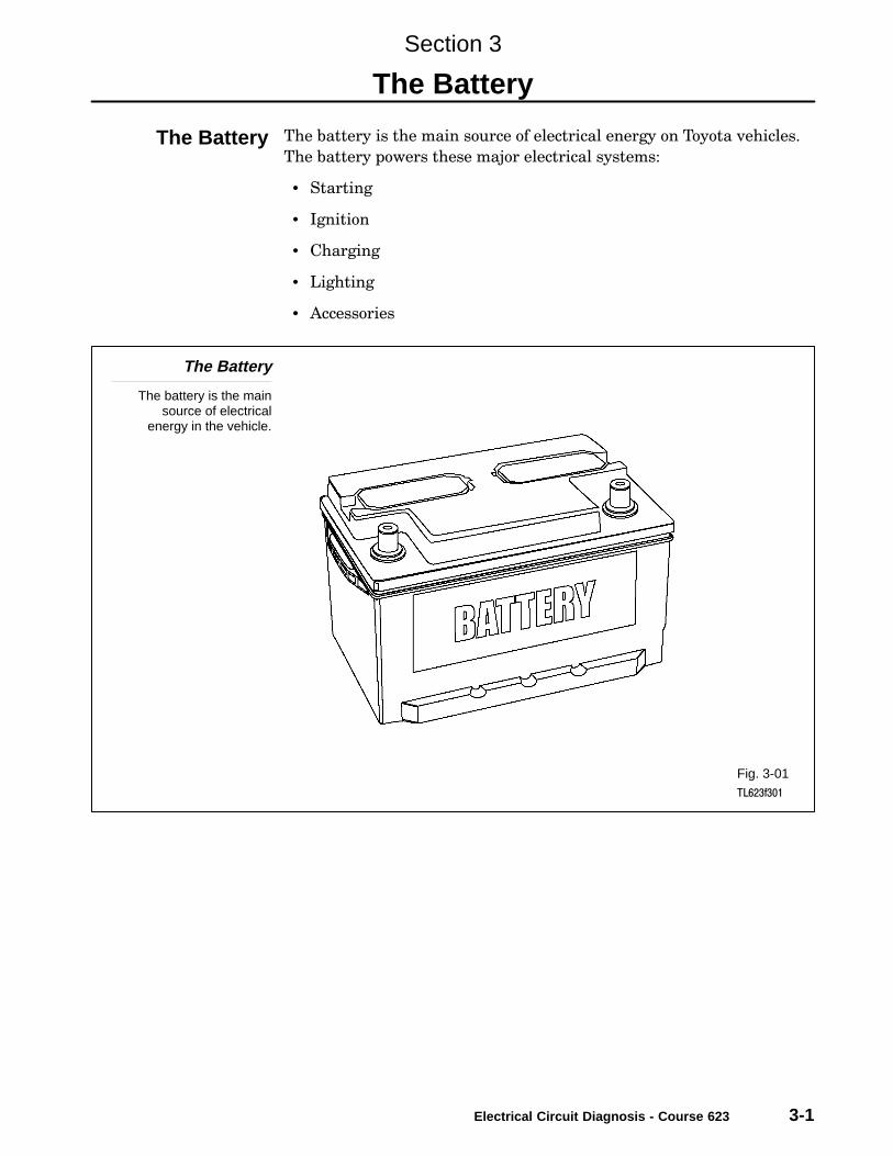
The battery is the main source of electrical energy on Toyota vehicles.
The battery powers these major electrical systems:
• Starting
• Ignition
• Charging
• Lighting
• Accessories
The Battery
The battery is the mainsource of electrical
energy in the vehicle.
Fig. 3-01TL623f301
Section 3
The Battery
The Battery

Section 3
3-2 TOYOTA Technical Training
Engine off − The battery provides energy to operate lighting and
accessories.
Engine starting − The battery provides energy to operate the starter
motor and ignition system during starting.
Engine running − The charging system provides most of the energy
required with the engine running; the battery acts as a voltage stabilizer
to protect voltage sensitive circuits, particularly digital circuits.
Battery Functions
The battery provides energy to operatelights and accessories and to start
the engine. It also serves as avoltage stabilizer.
Fig. 3-02TL623f302
BatteryFunctions

The Battery
Electrical Circuit Diagnosis - Course 623 3-3
Lead−Acid − Virtually all automotive batteries are lead−acid batteries.
Two different metals, both lead compounds, are immersed in an acid
electrolyte. The chemical reaction produced provides electrical energy.
Low Maintenance/No Maintenance − Some manufacturers use this
terminology. �Low maintenance" means that electrolyte can be added.
�No maintenance" means that the battery is sealed.
Vented − Most batteries have removable vented caps that are used to
check electrolyte level and add distilled water as necessary to restore
the level. The caps also allow hydrogen gas, a byproduct of battery
charging, to escape during charging.
Sealed − Some lead−acid batteries are sealed, that is, there are no
removable caps to check electrolyte or replenish it. Some of these
batteries have a small �eye" to indicate charge level. Still others are
sealed, but include connections to external vent tubes.
For all types of batteries, always follow the manufacturers’
recommendations for charging and testing.
Lead-Acid Battery
Lead-acid batteries arecalled by different names:
vented, sealed, lowmaintenance, and no
maintenance.
Fig. 3-03TL623f300
Battery Type
NOTE
Section 3
3-4 TOYOTA Technical Training
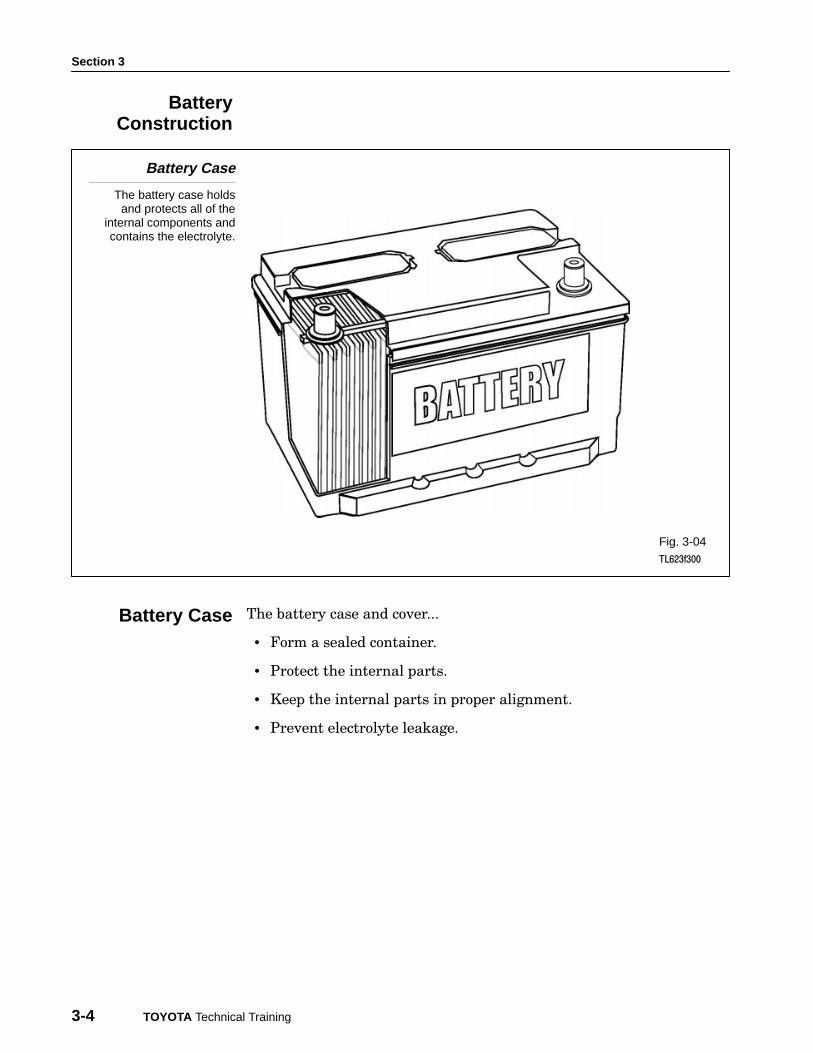
Battery Case
The battery case holdsand protects all of the
internal components andcontains the electrolyte.
Fig. 3-04TL623f300
The battery case and cover...
• Form a sealed container.
• Protect the internal parts.
• Keep the internal parts in proper alignment.
• Prevent electrolyte leakage.
BatteryConstruction
Battery Case

The Battery
Electrical Circuit Diagnosis - Course 623 3-5
Two types of plates are used in a battery: positive and negative.
Positive − Positive plates are made of antimony covered with an active
layer of lead dioxide (PbO2).
Negative − Negative plates are made of lead covered with an active
layer of sponge lead (Pb).
Only the surface layers on both plates take part in the chemical reaction.
Plate surface area − As the surface area of the plates increases, so does
the current capacity of the battery. Surface area is determined by the size
of each plate, as well as the total number of plates in a battery. Generally
speaking, the larger the battery, the higher is its current capacity.
Surface area has no effect on battery voltage.
Positive andNegative Plates
Positive plates arecovered with lead dioxide
(PbO2); negative platesare made of lead (Pb).
Fig. 3-05TL623f305c
Plates
Section 3
3-6 TOYOTA Technical Training
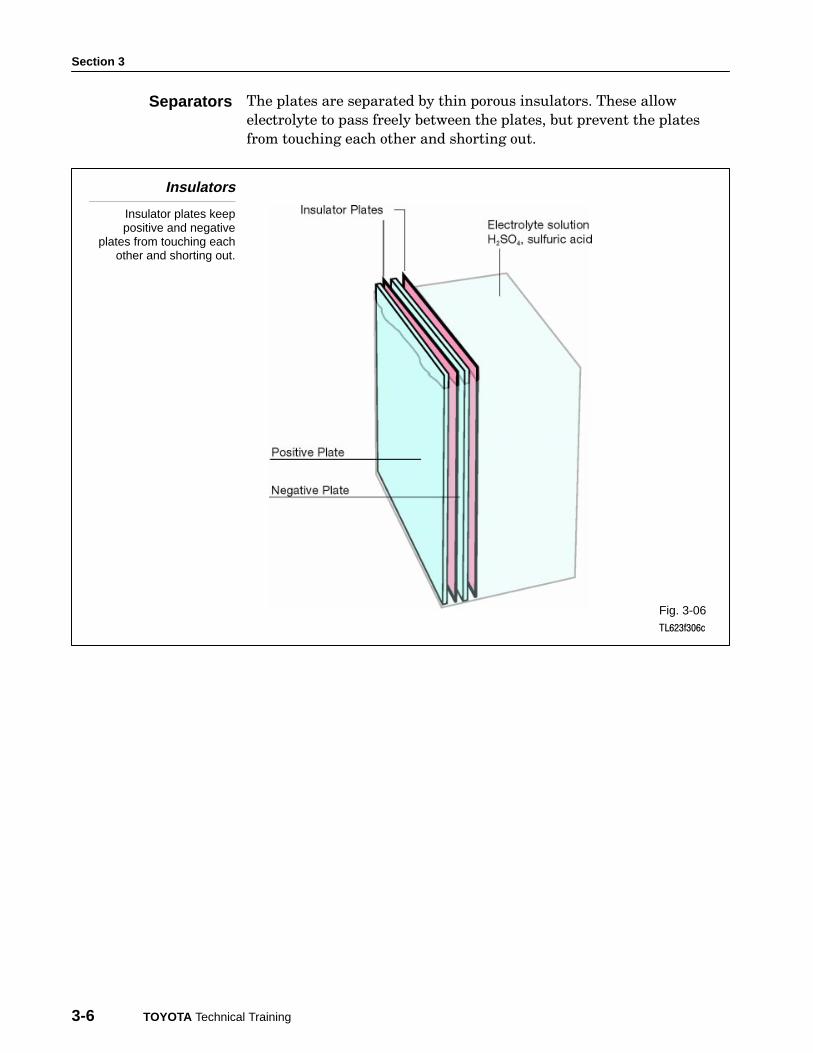
The plates are separated by thin porous insulators. These allow
electrolyte to pass freely between the plates, but prevent the plates
from touching each other and shorting out.
Insulators
Insulator plates keeppositive and negative
plates from touching eachother and shorting out.
Fig. 3-06TL623f306c
Separators
The Battery
Electrical Circuit Diagnosis - Course 623 3-7
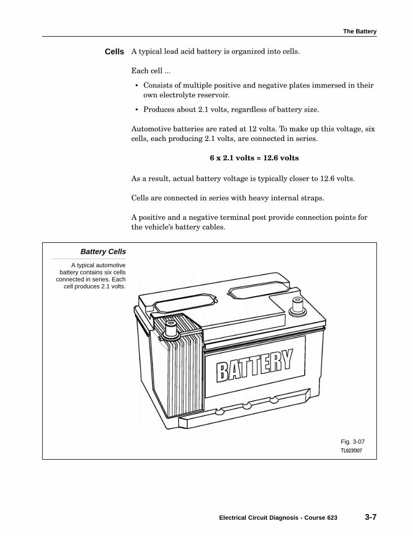
A typical lead acid battery is organized into cells.
Each cell ...
• Consists of multiple positive and negative plates immersed in their
own electrolyte reservoir.
• Produces about 2.1 volts, regardless of battery size.
Automotive batteries are rated at 12 volts. To make up this voltage, six
cells, each producing 2.1 volts, are connected in series.
6 x 2.1 volts = 12.6 volts
As a result, actual battery voltage is typically closer to 12.6 volts.
Cells are connected in series with heavy internal straps.
A positive and a negative terminal post provide connection points for
the vehicle’s battery cables.
Battery Cells
A typical automotivebattery contains six cells
connected in series. Eachcell produces 2.1 volts.
Fig. 3-07TL623f307
Cells

Section 3
3-8 TOYOTA Technical Training
On some batteries, vent caps allow a controlled release of hydrogen
gas. This gas forms naturally during battery recharging, whether by
the vehicle’s alternator or by an external charger.
Battery Vent Caps
Vent caps allow thecontrolled release ofhydrogen gas as the
battery charges.
Fig. 3-08TL623f308c
Venting System
The Battery
Electrical Circuit Diagnosis - Course 623 3-9
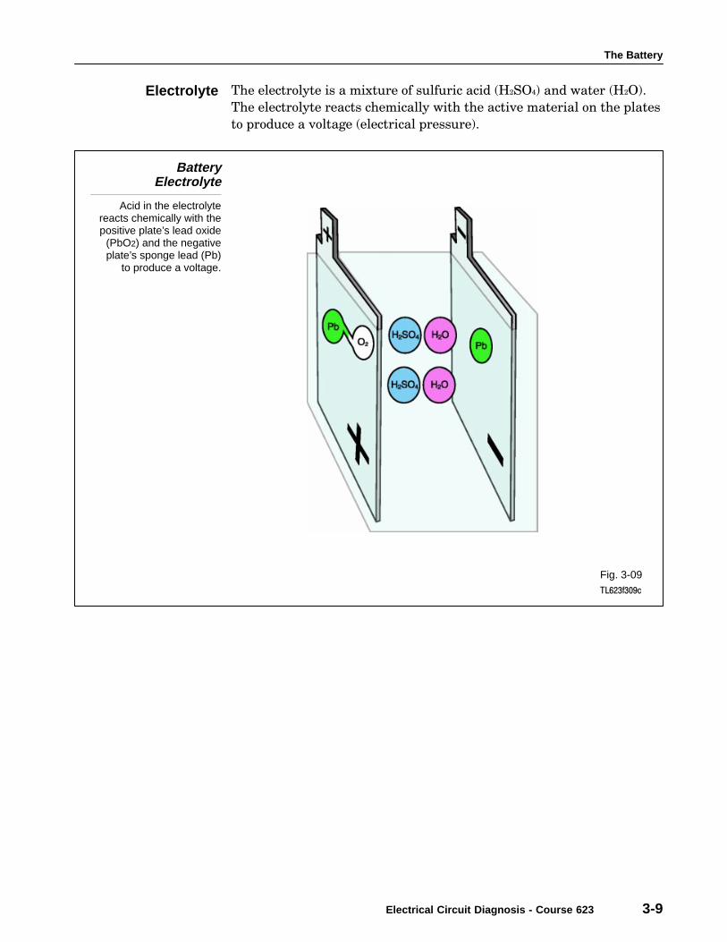
The electrolyte is a mixture of sulfuric acid (H2SO4) and water (H2O).
The electrolyte reacts chemically with the active material on the plates
to produce a voltage (electrical pressure).
BatteryElectrolyte
Acid in the electrolytereacts chemically with thepositive plate’s lead oxide
(PbO2) and the negativeplate’s sponge lead (Pb)
to produce a voltage.
Fig. 3-09TL623f309c
Electrolyte
Section 3
3-10 TOYOTA Technical Training
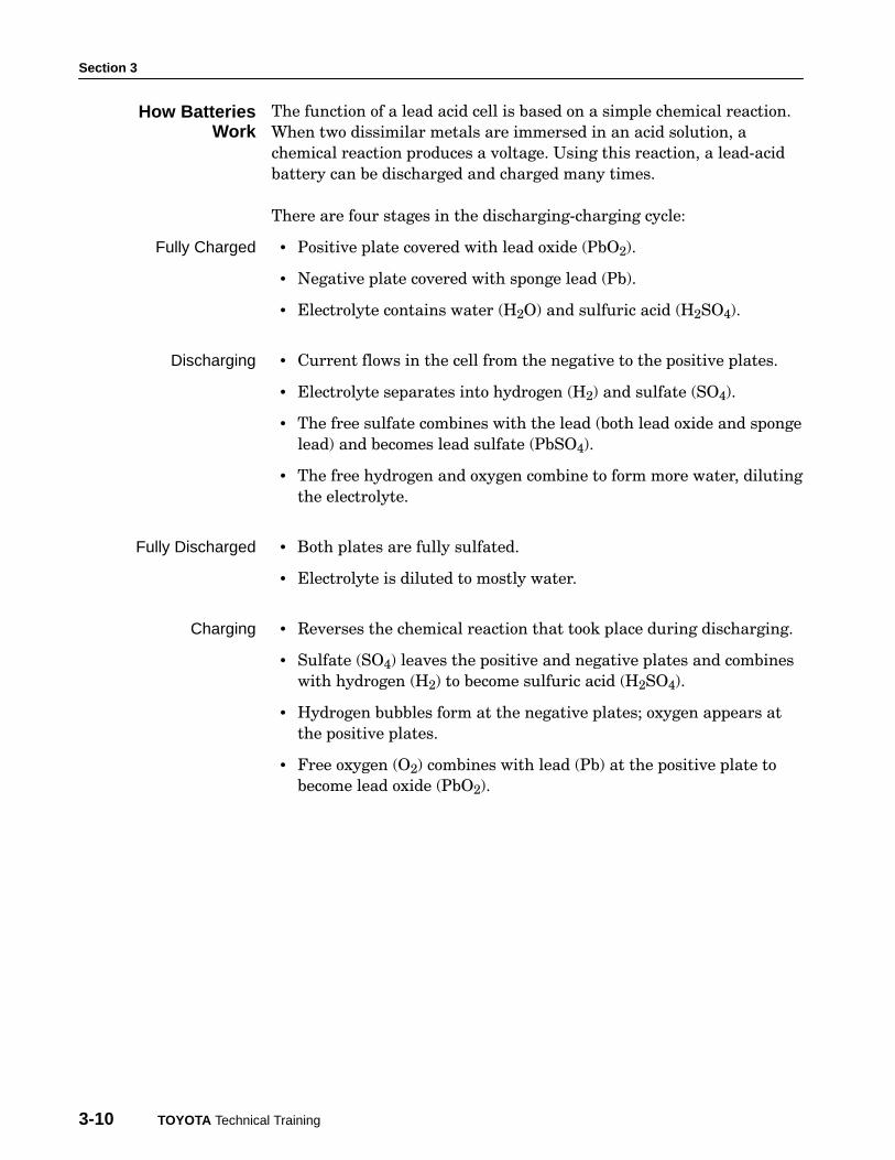
The function of a lead acid cell is based on a simple chemical reaction.
When two dissimilar metals are immersed in an acid solution, a
chemical reaction produces a voltage. Using this reaction, a lead−acid
battery can be discharged and charged many times.
There are four stages in the discharging−charging cycle:
• Positive plate covered with lead oxide (PbO2).
• Negative plate covered with sponge lead (Pb).
• Electrolyte contains water (H2O) and sulfuric acid (H2SO4).
• Current flows in the cell from the negative to the positive plates.
• Electrolyte separates into hydrogen (H2) and sulfate (SO4).
• The free sulfate combines with the lead (both lead oxide and sponge
lead) and becomes lead sulfate (PbSO4).
• The free hydrogen and oxygen combine to form more water, diluting
the electrolyte.
• Both plates are fully sulfated.
• Electrolyte is diluted to mostly water.
• Reverses the chemical reaction that took place during discharging.
• Sulfate (SO4) leaves the positive and negative plates and combines
with hydrogen (H2) to become sulfuric acid (H2SO4).
• Hydrogen bubbles form at the negative plates; oxygen appears at
the positive plates.
• Free oxygen (O2) combines with lead (Pb) at the positive plate to
become lead oxide (PbO2).
How BatteriesWork
Fully Charged
Discharging
Fully Discharged
Charging
The Battery
Electrical Circuit Diagnosis - Course 623 3-11
Lead Acid Chemical Reaction
The charging-discharging cycle hasfour distinct stages, all based on
a reversible chemical reactionwith lead and sulfuric acid.
Fig. 3-10TL623f310c

Section 3
3-12 TOYOTA Technical Training
An automotive battery must be able to crank the engine for starting
and still have enough reserve capacity to operate the vehicle systems
once the engine starts.
Battery capacity is:
• The amount of electrical energy the battery can deliver when fully
charged.
• Determined by the size and total number of plates and the volume
and strength of the electrolyte.
Refer to the manufacturer’s specification for information specific to a
particular Toyota vehicle.
While it is operating the starter, the battery experiences a large
discharge current.
The measure of a battery’s ability to provide this current is expressed
as Cold−Cranking Amperes, or CCA Rating.
The CCA Rating specifies (in amperes) the discharge current a fully
charged battery can deliver ...
• at 0° F (−18° C),
• for 30 seconds,
• while maintaining at least 1.2 volts per cell (or 7.2 volts total for a
six−cell, 12−volt battery).
Batteries in Toyota vehicles typically have a CCA rating between 350
to 560 amperes, depending on vehicle model. Refer to TIS to obtain
information for specific Toyota vehicles.
The battery must provide reserve energy for the ignition system and
for lights and accessories if the charging system fails.
The Reserve Capacity rating measures (in minutes) the amount of time
a fully charged battery can ...
• discharge at 25 amperes, while maintaining a voltage of at least
1.75 volts per cell (total of 10.5 volts for a 6−cell, 12−volt battery).
Batteries in Toyota vehicles typically have an RC rating between 55
and 115 minutes, depending on vehicle model. Refer to TIS to obtain
information for specific Toyota vehicles.
Capacity Ratings
Cold-CrankingAmperes
Reserve Capacity(RC)
The Battery
Electrical Circuit Diagnosis - Course 623 3-13
The Ampere−Hours, or AH rating, is another important measure of a
battery’s design performance.
The AH rating expresses the discharge current a fully charged battery
can deliver for 20 hours ...
• at 80° F (27° C),
• while maintaining a voltage of at least 1.75 volts per cell (total of
10.5 volts for a 6−cell, 12−volt battery).
A battery that can deliver 4 amps for 20 hours is rated at 80 amp−hours.
Batteries in Toyota vehicles typically have an AH rating between 40
and 80 amp−hours, depending on vehicle model. Refer to TIS to obtain
information for specific Toyota vehicles.
Ampere-Hours(AH)
EXAMPLE

Section 3
3-14 TOYOTA Technical Training
Battery service should always begin with a thorough visual inspection.
Such an inspection may reveal simple, easily corrected problems or
problems that require battery replacement without further testing.
Include these steps in a visual inspection:
1. Check for cracks in the battery case. Check particularly around
battery terminals. These are sometimes overstressed when
removing and installing battery cables. Replace the battery if there
is any evidence of cracking.
2. Check for cracked or broken cables or connections. Replace cables
or connectors as necessary.
3. Check for corrosion on terminals and dirt or acid on the case top.
Clean the terminals and case top with a mixture of water and
baking soda. Wire brush heavy corrosion on the terminals.
4. Check for a loose battery hold−down and loose cable connections.
Tighten as needed.
5. On batteries with removable vent caps, remove the caps and check
the electrolyte level. Add distilled water to each cell to restore the
level if necessary. Avoid overfilling and never add additional acid.
Tap water adds contaminants, and will reduce battery efficiency.
Visual Inspection
A visual inspection canreveal easy-to-correct
problems with the batteryand conditions that will
require batteryreplacement.
Fig. 3-11TL623f311c
Visual Inspection
The Battery
Electrical Circuit Diagnosis - Course 623 3-15
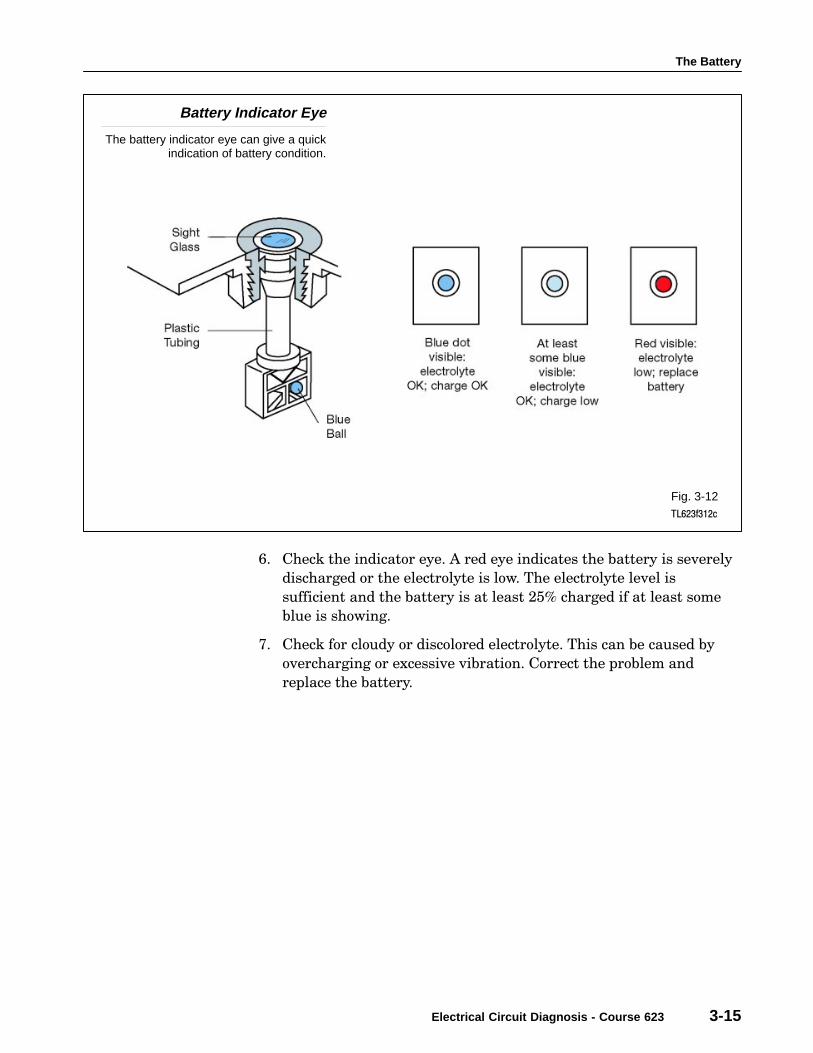
Battery Indicator Eye
The battery indicator eye can give a quickindication of battery condition.
Fig. 3-12TL623f312c
6. Check the indicator eye. A red eye indicates the battery is severely
discharged or the electrolyte is low. The electrolyte level is
sufficient and the battery is at least 25% charged if at least some
blue is showing.
7. Check for cloudy or discolored electrolyte. This can be caused by
overcharging or excessive vibration. Correct the problem and
replace the battery.

Section 3
3-16 TOYOTA Technical Training
Safety should be your first consideration whenever you inspect, test, or
replace a lead acid battery. The electrolyte contains sulfuric acid. This
acid can burn your skin, injure your eyes, and damage the vehicle, your
tools, or your clothing.
If you splash electrolyte onto your skin or into your eyes, immediately
rinse it away with large amounts of clean water. Contact a doctor
immediately.
If you spill electrolyte onto any part of the vehicle, neutralize the acid
with a solution of baking soda and water, then rinse liberally to remove
any residue.
When a battery is charging, the electrolyte may release gasses
(hydrogen and oxygen). Hydrogen gas is explosive, and oxygen
supports combustion. A flame or spark near a charging battery can
cause an explosion.
Take the following precautions when working with automotive batteries:
• Wear gloves and safety glasses.
• Never use spark−producing tools near the battery.
• Never lay any tools on the battery.
• If it is necessary to remove the battery cables, always remove the
ground first.
• When connecting battery cables, always connect the ground cable
last.
• Do not use the battery ground terminal when checking for ignition
spark.
• Take care not to spill electrolyte into your eyes, onto your skin, and
onto any part of the vehicle.
• If you mix electrolyte, pour the acid into the water (not the water
into the acid).
• Always follow the recommended procedures for battery testing,
charging, and for connecting jumper cables between two batteries.
Safety First
Precautions

The Battery
Electrical Circuit Diagnosis - Course 623 3-17
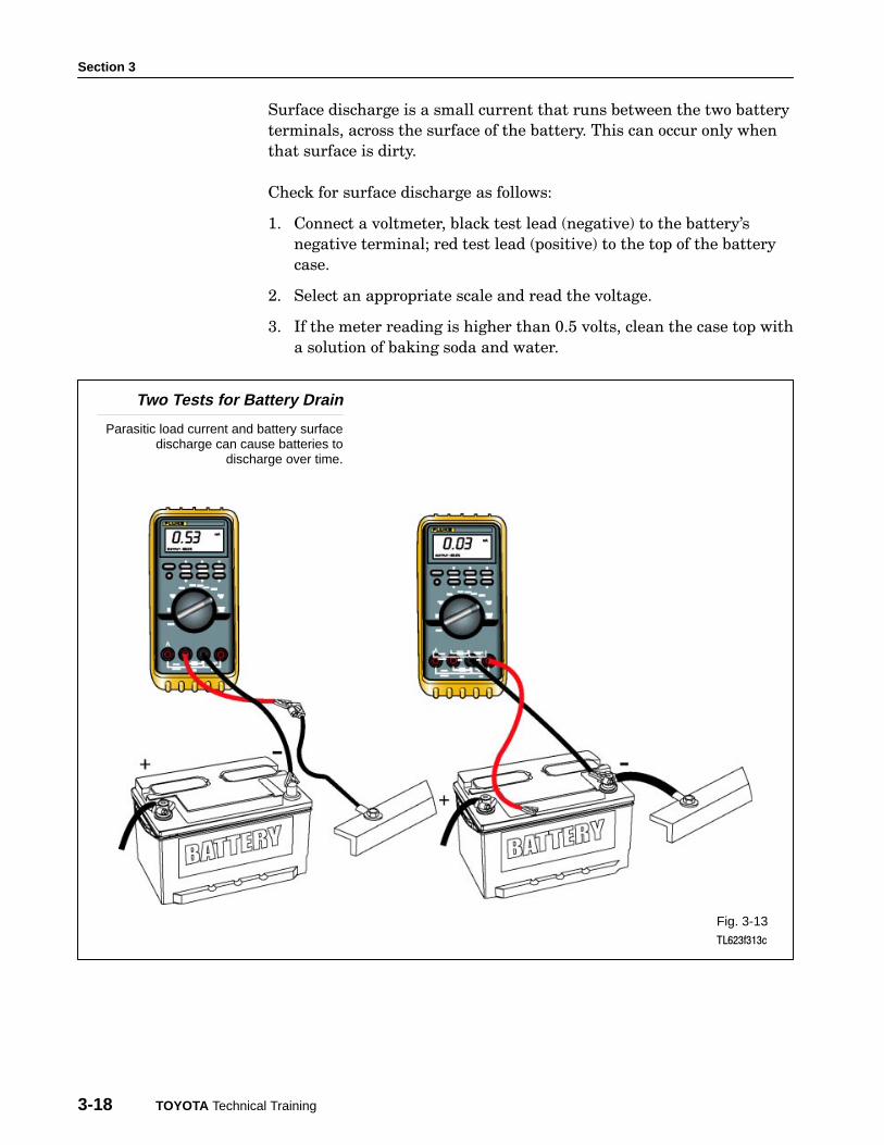
There are two tests for battery drain:
1. Parasitic load
2. Surface discharge
A parasitic load is created by a device that draws current even when
the ignition switch is turned to �Off." Even a small current can
discharge the battery, if the vehicle is not used for an extended time.
Check for a parasitic load as follows:
1. Connect an ammeter in series between the battery negative
terminal and the ground cable connector.
2. Select the appropriate scale and read the current draw.
3. Toyota vehicles typically draw between 20 and 75 milliamps (this is
current used to maintain electronic memories).
4. Any reading higher than 100 milliamps is unacceptable. Locate and
correct the cause of the excess parasitic drain.
5. Make sure that you wait a few minutes before checking for parasitic
load. After the vehicle is shut down or a door is opened, parasitic load
may be 50−75 milliamps, depending on model, for a few minutes.
Battery Drain Tests
Section 3
3-18 TOYOTA Technical Training
Surface discharge is a small current that runs between the two battery
terminals, across the surface of the battery. This can occur only when
that surface is dirty.
Check for surface discharge as follows:
1. Connect a voltmeter, black test lead (negative) to the battery’s
negative terminal; red test lead (positive) to the top of the battery
case.
2. Select an appropriate scale and read the voltage.
3. If the meter reading is higher than 0.5 volts, clean the case top with
a solution of baking soda and water.
Two Tests for Battery Drain
Parasitic load current and battery surfacedischarge can cause batteries to
discharge over time.
Fig. 3-13TL623f313c

The Battery
Electrical Circuit Diagnosis - Course 623 3-19
You can use a battery analyzer to obtain an indication of battery
condition that is more accurate than just its state of charge. The
Midtronics Micropro 815 Battery Analyzer uses conductance testing to
evaluate the condition of the plates inside the battery.
There are several advantages of using this battery analyzer:
• Battery can be tested even when it’s not fully charged.
• No need to charge battery before testing; can be tested as soon as
vehicle arrives for service.
• Information from analyzer lets you make a quick decision.
• Reduces costly mistakes.
Micropro 815Battery Analyzer
A battery analyzercan help you make a
quick and accuratedetermination of
battery condition.
Fig. 3-14TL623f314c
Micropro815 Battery
Analyzer
Section 3
3-20 TOYOTA Technical Training
Prepare the battery for testing:
• Remove the battery’s surface charge.
• Disconnect the battery from the vehicle.
• Make sure the terminals are clean and free of corrosion.
• If the battery has removable vent caps, check the electrolyte level.
Top up with distilled water if needed.
To remove a battery’s surface charge, turn on the headlights with the
engine off. Leave the lights on for one minute.
You can test batteries either connected to or disconnected from the
vehicle. In general, you get more reliable results with the battery
disconnected. If you do leave the battery connected for testing, turn off all
lights and accessories and set the ignition switch to the OFF position.
Preparing theBattery
To get the most accurateresults, make sure the
battery terminal posts areclean for testing.
Fig. 3-15TL623f315
Preparing theBattery for
Analyzer Tests

The Battery
Electrical Circuit Diagnosis - Course 623 3-21
Set up the battery analyzer as follows:
1. Connect the analyzer’s red lead to the positive battery terminal.
2. Connect the black lead to the negative battery terminal.
3. Check the analyzer’s display. It should illuminate and show four
zeros to indicate a good connection. The analyzer’s display will not
illuminate if there is a poor connection.
Connections − The teeth on both sides of each clamp must contact
the battery terminal. Rock both clamps back and forth to ensure a
good electrical connection.
4. Proceed to Testing the Battery (on the next page) if you have not
charged the battery before test.
5. Press the Test Mode key once if you charged the battery before the
test. The �After Charge" LED will light.
Press the Test Mode key twice if battery temperature is 32° F (0° C)
or lower. The �Cold Battery" LED will light.
Analyzer TestConnections
The battery analyzer’sclamp teeth must contactthe battery terminal post
on both sides.
Fig. 3-16TL623f316
Setting Up theBattery Analyzer
Section 3
3-22 TOYOTA Technical Training
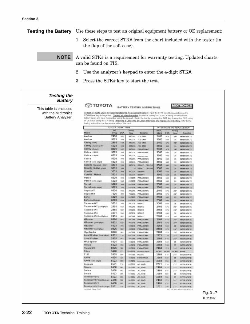
Use these steps to test an original equipment battery or OE replacement:
1. Select the correct STK# from the chart included with the tester (in
the flap of the soft case).
A valid STK# is a requirement for warranty testing. Updated charts
can be found on TIS.
2. Use the analyzer’s keypad to enter the 4−digit STK#.
3. Press the STK# key to start the test.
Testing theBattery
This table is enclosedwith the Midtronics
Battery Analyzer.
Fig. 3-17TL623f317
Testing the Battery
NOTE
The Battery
Electrical Circuit Diagnosis - Course 623 3-23
Use these steps to test a non−OE battery.
For battery with CCA rating:
1. Find the CCA (cold−cranking amps) rating on the battery label.
2. Enter the rating number via the keypad.
3. Press the CCA key to start the test.
For battery with a CA (cranking amps) rating:
1. Find the CA rating on the battery label.
2. Enter the rating number via the keypad.
3. Press the CA key to start the test.
Use this procedure if you cannot determine any usable rating
for a battery to be tested:
1. Find an STK# on the chart that is recommended for the vehicle in
which the battery is installed.
2. Use the analyzer’s keypad to enter the 4−digit STK#.
3. Press the STK# key to start the test.

Section 3
3-24 TOYOTA Technical Training
The results will be displayed in the Battery Condition area of the panel.
Good return to service − The battery is in good condition and ready
to return to service.
Charge and return to service − The battery is good, but must be
fully charged before returning to service.
Charge and retest − The test result is inconclusive. �Quick Charge"
the battery and retest using the After Charge test mode.
Replace − The battery must be replaced. Press the STK#/CODE key to
show the warranty code for the repair order.
Interpreting the Results
The battery analyzer lights one of theseLED’s to tell you the battery condition.
Fig. 3-18TL623f318c
Interpretingthe Results

The Battery
Electrical Circuit Diagnosis - Course 623 3-25
Fast charging is used to charge the battery for a short period of time
with a high rate of current. Fast charging may shorten battery life. If
time allows, slow charging is preferred. Some low maintenance
batteries cannot be fast charged.
1. Preparation for charging:
− Clean dirt, dust, or corrosion off the battery; if necessary, clean
the terminals.
− Check the electrolyte level and add distilled water if needed.
− If the battery is to be charged while on the vehicle, be sure to
disconnect both (−) (+) terminals.
2. Determine the charging current and time for fast charging:
− Some chargers have a test device for determining the charging
current and required time.
− If the charger does not have a test device, refer to the chart to
determine current and time.
ÁÁÁÁÁÁÁÁÁÁÁÁÁÁÁÁÁÁÁÁÁÁÁÁÁÁÁÁÁÁÁÁÁÁÁÁÁÁÁÁÁÁÁÁÁÁÁÁÁÁÁÁÁÁÁÁÁÁÁÁÁÁÁÁÁÁÁÁÁÁÁÁÁÁÁÁÁÁÁÁÁÁÁÁÁÁÁÁÁÁÁÁÁÁÁÁÁÁÁ
Typical Charging Rates for Fully Discharcled Batteries
ÁÁÁÁÁÁÁÁÁÁÁÁÁÁÁÁÁÁ
Reserve CapacityRating
ÁÁÁÁÁÁÁÁÁÁÁÁÁÁÁÁÁÁÁÁÁÁÁÁÁÁÁ
20-Hour Rating ÁÁÁÁÁÁÁÁÁÁÁÁÁÁÁ
5 Amperes ÁÁÁÁÁÁÁÁÁÁÁÁ
10 AmperesÁÁÁÁÁÁÁÁÁÁÁÁÁÁÁ
20 AmperesÁÁÁÁÁÁÁÁÁÁÁÁÁÁÁ
30 AmperesÁÁÁÁÁÁÁÁÁÁÁÁÁÁÁ
40 Amperes
ÁÁÁÁÁÁÁÁÁÁÁÁ
75 Minutes or lessÁÁÁÁÁÁÁÁÁÁÁÁÁÁÁÁÁÁ
50 Ampere-Hours or less ÁÁÁÁÁÁÁÁÁÁ
10 Hours ÁÁÁÁÁÁÁÁ
5 Hours ÁÁÁÁÁÁÁÁÁÁ
2½ HoursÁÁÁÁÁÁÁÁÁÁ
2 Hours ÁÁÁÁÁÁÁÁÁÁÁÁÁÁÁÁ
ÁÁÁÁÁÁÁÁÁÁÁÁ
Above 75 to 115Minutes
ÁÁÁÁÁÁÁÁÁÁÁÁÁÁÁÁÁÁÁÁÁÁÁÁÁÁÁ
Above 50 to 75 Ampere-Hours
ÁÁÁÁÁÁÁÁÁÁÁÁÁÁÁ
15 HoursÁÁÁÁÁÁÁÁÁÁÁÁ
7½ HoursÁÁÁÁÁÁÁÁÁÁÁÁÁÁÁ
3¼ HoursÁÁÁÁÁÁÁÁÁÁÁÁÁÁÁ
2½ HoursÁÁÁÁÁÁÁÁÁÁÁÁÁÁÁ
2 Hours
ÁÁÁÁÁÁÁÁÁÁÁÁÁÁÁÁÁÁ
Above 115 to 160Minutes
ÁÁÁÁÁÁÁÁÁÁÁÁÁÁÁÁÁÁÁÁÁÁÁÁÁÁÁ
Above 75 to 100 Ampere-Hours
ÁÁÁÁÁÁÁÁÁÁÁÁÁÁÁ
20 HoursÁÁÁÁÁÁÁÁÁÁÁÁ
10 HoursÁÁÁÁÁÁÁÁÁÁÁÁÁÁÁ
5 HoursÁÁÁÁÁÁÁÁÁÁÁÁÁÁÁ
3 HoursÁÁÁÁÁÁÁÁÁÁÁÁÁÁÁ
2½ Hours
ÁÁÁÁÁÁÁÁÁÁÁÁÁÁÁÁÁÁ
Above 160 to 245Minutes
ÁÁÁÁÁÁÁÁÁÁÁÁÁÁÁÁÁÁÁÁÁÁÁÁÁÁÁ
Above 100 to 150 Ampere-Hours
ÁÁÁÁÁÁÁÁÁÁÁÁÁÁÁ
30 HoursÁÁÁÁÁÁÁÁÁÁÁÁ
15 HoursÁÁÁÁÁÁÁÁÁÁÁÁÁÁÁ
7½ HoursÁÁÁÁÁÁÁÁÁÁÁÁÁÁÁ
5 HoursÁÁÁÁÁÁÁÁÁÁÁÁÁÁÁ
3½ Hours
3. Using the charger:
− Make sure that the main switch and timer switch are OFF and
the current adjust switch is at the minimum position.
− Connect the positive lead of the charger to the battery’s positive
terminal (+) and the negative lead of the charger to the battery’s
negative terminal (−).
− Connect the charger’s power cable to the electric outlet.
− Set the voltage switch to the correct battery voltage.
− Set the main switch at ON.
− Set the timer to the desired time and adjust the charging current
to the predetermined amperage.
Fast Charging

Section 3
3-26 TOYOTA Technical Training
4. After the timer is OFF, check the charged condition using a
voltmeter.
− Correct Voltage: 12.6 volts or higher.
If the voltage does not increase, or if gas is not emitted no matter how
long the battery is charged, there may be a problem with the battery,
such as an internal short.
5. When the voltage reaches the proper reading,
− Set the current adjust switch to minimum.
− Turn off the main switch of the charger.
− Disconnect the charger cable from the battery terminals.
− Wash the battery case to clean off the acid emitted.
High charging rates are not good for completely charging a battery. To
completely charge a battery, slow charging with a low current is required.
Slow charging procedures are the same as those for fast charging,
except for the following:
1. The maximum charging current should be less than 1/10th of the
battery capacity. For instance, a 40 AH battery should be slow
charged at 4 amps or less.
2. Set the charger switch to the slow position (if provided).
3. Readjust the current control switch, if needed, while charging.
4. As the battery gets near full charge, hydrogen gas is emitted. When
there is no further rise in battery voltage for more than one hour,
the battery is completely charged.
− Battery Voltage: 12.6 volts or higher.
Slow Charging

The Battery
Electrical Circuit Diagnosis - Course 623 3-27
Jump starting requires proper battery connecting procedures to
prevent sparks. Jump start a vehicle using the following procedure:
1. Connect the two positive cables using the positive jumper leads.
2. Connect one end of the negative jumper lead to the booster battery.
3. Connect the other lead of the negative jumper lead to a good ground
on the vehicle with the dead battery. This location could be:
• The vehicle frame.
• The engine block.
Using this method ensures that any possible sparks occur away from
the battery.
Battery jumper leads should be high quality and have a large wire
gauge (such as 4 gauge) to safely carry the current necessary to jump
start a vehicle.
Never try to jump start a vehicle with a visibly damaged battery or if
no battery is present. Vehicle damage and risk of battery explosion are
possible.
Jump Starting
Jump start as follows:1. Positive to positive,
2. Negative to good battery,3. Negative to good ground of
vehicle with dead battery.
Fig. 3-19TL623f319c
Jump Starting
NOTE
CAUTION

Section 3
3-28 TOYOTA Technical Training