section - deeproot 32 94 50 ... net‐shaped synthetic polymer‐coated fibers that ... storage...
TRANSCRIPT

SECTION 32 94 50 SILVA CELLS
32 94 50 ‐ Silva Cell © 2011 Deep Root Partners, L.P. Version 2.30 Updated 12/16/11 ‐ 1 ‐
SILVA CELLS This specification defines material and performance requirements for the Silva Cell system. The SPECIFICATION EDITOR should adapt these specifications to reflect specific project requirements. Some elements in these specifications require coordination with project drawings. These items are noted “as indicated on plans or drawings.” See the DeepRoot website (www.deeproot.com) for questions. DeepRoot can assist in evaluating and sizing project‐specific design elements for Silva Cells stormwater applications.
SECTION 32 94 50 SILVA CELLS
32 94 50 ‐ Silva Cell © 2011 Deep Root Partners, L.P. Version 2.30 Updated 12/16/11 ‐ 2 ‐
GENERAL
1.1 RELATED DOCUMENTS
A. Drawings and general provisions of the Contract, including General and Supplementary Conditions and Division 01 Specification Sections, apply to this Section.
1.2 SUMMARY
A. Section Includes:
1. Furnishing and installing Silva Cell system, including: geotextile, geogrids, aggregates, sub base material, backfill, drainage system, root barrier, compost, and the installation of planting soil.
B. Related Sections
1. Division 32 – Exterior Improvements
a. Section 32 94 53 Root Barrier
b. Section 32 94 56 Planting Soil for Silva Cells
1.3 DEFINITIONS
A. Aggregate Sub Base (below Cell frame): Aggregate material between the bottom of the Silva Cell frame and the compacted subgrade below, designed to distribute loads from the frame to the subgrade.
B. Aggregate Base Course (above Cell deck): Aggregate material between the paving and the top of the Silva Cell deck below designed to distribute loads across the top of the deck.
C. Aggregate Setting Bed – For Pavers (above Cell deck): Aggregate material between the aggregate base course and unit surface pavers, designed to act as a setting bed for the pavers.
D. Backfill: The earth used to replace or the act of replacing earth in an excavation beside the Silva Cell frames to the excavation extents.
E. Bridging Slab: Bridging slabs are to be used in locations where spacing larger than 3 inches (75 mm) is necessary between Silva Cell frames.
F. Compost: Organic material subjected to composting processes
SECTION 32 94 50 SILVA CELLS
32 94 50 ‐ Silva Cell © 2011 Deep Root Partners, L.P. Version 2.30 Updated 12/16/11 ‐ 3 ‐
G. Finish Grade: Elevation of finished surface of planting soil or paving.
H. Geogrid: Net‐shaped synthetic polymer‐coated fibers that provide a stabilizing force within soil structure as the fill interlocks with the grid.
I. Geotextile: A geosynthetic fabric, applied to either the soil surface or between materials, providing filtration, separation, or stabilization properties.
J. Inspection Riser for Drainage: Vertical, perforated pipe installed at tree openings to allow access for visual inspection of water levels at base of Silva Cell system. Designers to determine frequency of risers, one riser for every three trees is recommended. **May be modified to act as a cleanout for drain lines. This variation would not be perforated.
K. Inspection Riser for Soil: Vertical pipe installed within pavement section to allow access for visual inspection of soils within Silva Cell system. Designers to determine frequency of risers based on soil inspection goals. One riser for every two trees is recommended.
L. Irrigation: Trees planted in the Silva Cell system must receive adequate water to ensure survival of the living system during periods of drier weather. Harvest of natural rainwater or supplemental water must be a part of the system, either through pressurized or non‐pressurized systems, within the soil of the Silva Cell system.
M. Planting Soil: Soil as defined in Division 2 Section 32 94 56, Planting Soil for Silva Cells, intended to fill the frames and other planting spaces.
N. Root Barrier: Plastic root diversion device.
O. Root package: The earthen package containing the root system of the tree as shipped from the nursery.
P. Silva Cells: Plastic structural cellular system with posts, beams and decks designed to be filled with planting soil for tree rooting and support of vehicle loaded pavements. The soil within the cells may also be used as part of rainwater filtering, retention and detention systems.
Q. Subgrade: Surface or elevation of subsoil remaining after completing excavation, or top surface of a fill or backfill.
R. Strongback: Modified Silva Cell frame designed to be attached to top of Silva Cells for stability while installing planting soil and backfill.
S. Subsoil: All soil beneath the topsoil layer of the soil profile, and typified by the lack of organic matter and soil organisms.
T. Tree: A perennial woody plant with one or several trunks and a distinct crown and intended to become large enough to shade people and or vehicles.
SECTION 32 94 50 SILVA CELLS
32 94 50 ‐ Silva Cell © 2011 Deep Root Partners, L.P. Version 2.30 Updated 12/16/11 ‐ 4 ‐
U. Zip Tie: A tensioning device or tool used tie similar or different materials together with a specific degree of tension.
1.4 SUBMITTALS
A. Upon forty‐five (45) days prior to start of installation of items in this section, the Contractor shall provide submittals required in this section to the landscape architect for review and approval.
B. Product Data: For each type of product, submit manufacturer's product literature with technical data sufficient to demonstrate that the product meets these specifications.
1. For bulk materials, including soils and aggregates, Include analysis of the materials by a recognized laboratory made that demonstrates that the material meets the specification requirements.
2. Silva Cell manufacturer's letter of review and approval of the project, plans, details and specifications for compliance with product installation requirements.
C. Silva Cell System Mock Up:
1. Prior to the installation of Silva Cells, construct a mock up of the complete installation at the site. The installation of the mock up shall be in the presence of the landscape architect.
2. The mock up shall be a minimum of 100 square feet in area and include the complete Silva Cell system installation with sub base compaction, drainage installation, base course aggregate and geotextile as required, geogrids, backfill, planting soil with compaction, decks, top geotextile and all necessary accessories.
3. The mock up area may remain as part of the installed work at the end of the project provided that it remains in good condition and meets all the conditions of the specifications.
D. Compaction testing results: Submit results of all compaction testing required by the specifications including the bulk density test of the mock up and installed soil to the landscape architect for approval.
E. Qualification Data: Submit documentation of the qualifications of the Silva Cell installer sufficient to demonstrate that the installer meets the requirements of paragraph "Quality Assurance".
1.5 SEQUENCING AND SCHEDULING
A. General: Prior to the start of Work, prepare a detailed schedule of the work for coordination with other trades.

SECTION 32 94 50 SILVA CELLS
32 94 50 ‐ Silva Cell © 2011 Deep Root Partners, L.P. Version 2.30 Updated 12/16/11 ‐ 5 ‐
B. Schedule all utility installations prior to beginning work in this section.
C. Where possible, schedule the installation of Silva Cells after the area is no longer required for use by other trades and work. Protect installed Silva Cells from damage in the event that work must occur over or adjacent to the completed Silva Cells.
1.6 QUALITY ASSURANCE
A. Installer Qualifications: Silva Cells and related products shall be installed by a qualified installer whose work has resulted in successful installation of planting soils and planter drainage systems, underground piping, chambers and vault structures.
1. Submit list of completed projects of similar scope and scale to the Owner, demonstrating capabilities and experience.
2. The installer and the field supervisor shall have a minimum of five years successful experience with construction of similar scope in dense urban areas.
3. Installer's Field Supervision: Installer is required to maintain an experienced full‐time supervisor on Project site when work is in progress. This person shall be identified during the Pre‐installation Conference, with appropriate contact information provided, as necessary. The same supervisor shall be utilized throughout the Project, unless a substitution is submitted to and approved in writing by the Owner.
1.7 LAYOUT AND ELEVATION CONTROL
A. Provide layout and elevation control during installation of Silva Cells. Utilize grade stakes, benchmarks, surveying equipment and other means and methods to assure that layout and elevations conform to the layout and elevations indicated on the plans.
1.8 PERMITS AND CODE COMPLIANCE
A. Comply with applicable requirements of the laws, codes, ordinances and regulations of Federal, State and Municipal authorities having jurisdiction. Obtain necessary permits/approvals from all such authorities.
1.9 DELIVERY, STORAGE, AND HANDLING
A. Packaged Materials: Deliver packaged materials in original, unopened containers showing weight, certified analysis, name and address of manufacturer, and indication of conformance with state and federal laws, if applicable. Protect materials from deterioration during delivery and while on the project site.
B. Bulk Materials:

SECTION 32 94 50 SILVA CELLS
32 94 50 ‐ Silva Cell © 2011 Deep Root Partners, L.P. Version 2.30 Updated 12/16/11 ‐ 6 ‐
1. Do not deliver or place backfill, soils and soil amendments in frozen, wet, or muddy conditions.
2. Provide protection including tarps, plastic and or matting between all bulk materials and any finished surfaces sufficient to protect the finish material.
C. Provide erosion‐control measures to prevent erosion or displacement of bulk materials and discharge of soil‐bearing water runoff or airborne dust to adjacent properties, water conveyance systems, and walkways. Provide additional sediment control to retain excavated material, backfill, soil amendments and planting mix within the project limits as needed.
D. Silva Cells: Protect Silva Cells from damage during delivery, storage and handling.
1. Store under tarp to protect from sunlight when time from delivery to installation exceeds one week. Storage should occur on smooth surfaces, free from dirt, mud and debris
2. Handling is to be performed with equipment appropriate to the size (height) of Cells and site conditions, and may include, hand, handcart, forklifts, extension lifts, or small cranes, with care given to minimize damage to Silva Cell frames, decks and adjacent Silva Cells.
1.10 PROJECT CONDITIONS
A. Verification of Existing Conditions and Protection of New or Existing Improvements: Before proceeding with work in this section, the Installer shall carefully check and verify all dimensions, quantities, and grade elevations, and inform the landscape architect immediately of any discrepancies.
1. Carefully examine the civil, record, and survey drawings to become familiar with the existing underground conditions before digging. Verify the location of all aboveground and underground utility lines, infrastructure, other improvements, and existing trees, shrubs, and plants to remain including their root system, and take proper precautions as necessary to avoid damage to such improvements and plants.
2. In the event of conflict between existing and new improvements notify the landscape architect in writing and obtain written confirmation of any changes to the work prior to proceeding.
3. When new or previously existing utility lines are encountered during the course of excavation, notify the landscape architect in writing and make recommendations as to remedial action. Proceed with work in that area only upon approval of appropriate remedial action. Coordinate all work with the appropriate utility contractors, utility company or responsible public works agency.
B. Weather Limitations: Do not proceed with work when subgrades, soils and planting soils are in a wet, muddy or frozen condition.
SECTION 32 94 50 SILVA CELLS
32 94 50 ‐ Silva Cell © 2011 Deep Root Partners, L.P. Version 2.30 Updated 12/16/11 ‐ 7 ‐
C. Protect partially completed Silva Cell installation against damage from other construction traffic with highly visible construction tape, fencing, or other means until construction is complete. Prevent all non‐installation related construction traffic over the completed Silva Cell installation; allowing only loads less than the design loads.
1.11 PROTECTION
A. Protect open excavations and partially completed Silva Cell installation from access and damage when work is in progress, and following completion with highly visible construction tape, fencing, or other means until all construction is complete.
1.12 WARRANTY
A. Silva Cell manufacturer's product warranty shall apply. Submit manufacturer's product warranty.
1.13 PROJECT WORK
A. Coordinate installation with all other work that may impact the completion of the work.
1.14 PRECONSTRUCTION MEETING
A. Prior to the start of the installation of Silva Cells, meet at the site with the landscape architect, general contractor and the Silva Cells installer to review installation layout, procedures, means and methods.
PART 2 ‐ PRODUCTS
NOTE TO SPECIFICATION EDITOR: The Silva Cell system is designed to support AASHTO H‐20 loading. The entire assembly as described in this specification is necessary in order to meet this loading performance. Alternative assemblies may void Silva Cell warranties. Contact DeepRoot Partners for approval of alternative assemblies.
2.1 SILVA CELLS
A. Fiberglass‐reinforced polypropylene structures including frames and decks designed to support sidewalk loads and designed to be filled with soil for the purpose of growing tree roots, and rainwater filtering, detention and retention.
B. Silva Cell Frames: 400 mm x 600 mm x 1200 mm (16 inches x 24 inches x 48 inches).
C. Silva Cell Deck: 5 cm x 600 mm x 1200 mm (2 inches x 24 inches x 48 inches). Deck to include manufactured installed galvanized steel tubes.

SECTION 32 94 50 SILVA CELLS
32 94 50 ‐ Silva Cell © 2011 Deep Root Partners, L.P. Version 2.30 Updated 12/16/11 ‐ 8 ‐
D. Silva Cell Strongback: 400 mm x 600 mm x 150 mm (24 inches x 48 inches x 6 inches) modified Silva Cell Frame units designed to stiffen and align the frames as planting soil and backfill material is placed. Strongbacks are to be removed prior to placing decks. They are to be reused as the work progresses.
E. Silva Cell Deck Screws: Manufacturer's supplied stainless steel screws to attach decks to frames.
F. Manufacturer: DeepRoot Partners, L.P. (Deep Root); 530 Washington Street, San Francisco, CA 94111; 415.781.9700; 800.458.7668; fax 415.781.0191; www.deeproot.com..
2.2 ANCHORING SPIKES
A. 10" (250 mm) long X 19/64" (8 mm) diameter, spiral, galvanized timber spikes. Utilize 4 spikes in each frame on the first layer of Silva Cells to anchor the frames to the aggregate sub base.
2.3 SOLID AND PERFORATED DRAIN LINES
A. Any solid or perforated drain lines to be specified by project engineer.
2.4 INSPECTION RISER FOR DRAINAGE (where applicable):
A. Rigid, PVC schedule 40 pipe, 4” diameter.
B. Cap: Cast Iron solid threaded cleanout designed to fit standard PVC schedule 40 pipe‐fittings.
1. Products meeting this specification: Zurn Z 1440, Cast Iron Adjustable Cleanout, Zurn, 1801 Pittsburgh Avenue, Erie, PA 16502, 1‐877‐ZURN‐NOW. http://www.zurn.com/
2.5 INSPECTION RISER FOR SOIL (where applicable):
A. Rigid, PVC schedule 40 pipe, 6” diameter.
B. Cap: Cast Iron solid threaded cleanout designed to fit standard PVC schedule 40 pipe‐fittings.
1. Products meeting this specification: Zurn Z 1440, Cast Iron Adjustable Cleanout, Zurn, 1801 Pittsburgh Avenue, Erie, PA 16502, 1‐877‐ZURN‐NOW. http://www.zurn.com/
SECTION 32 94 50 SILVA CELLS
32 94 50 ‐ Silva Cell © 2011 Deep Root Partners, L.P. Version 2.30 Updated 12/16/11 ‐ 9 ‐
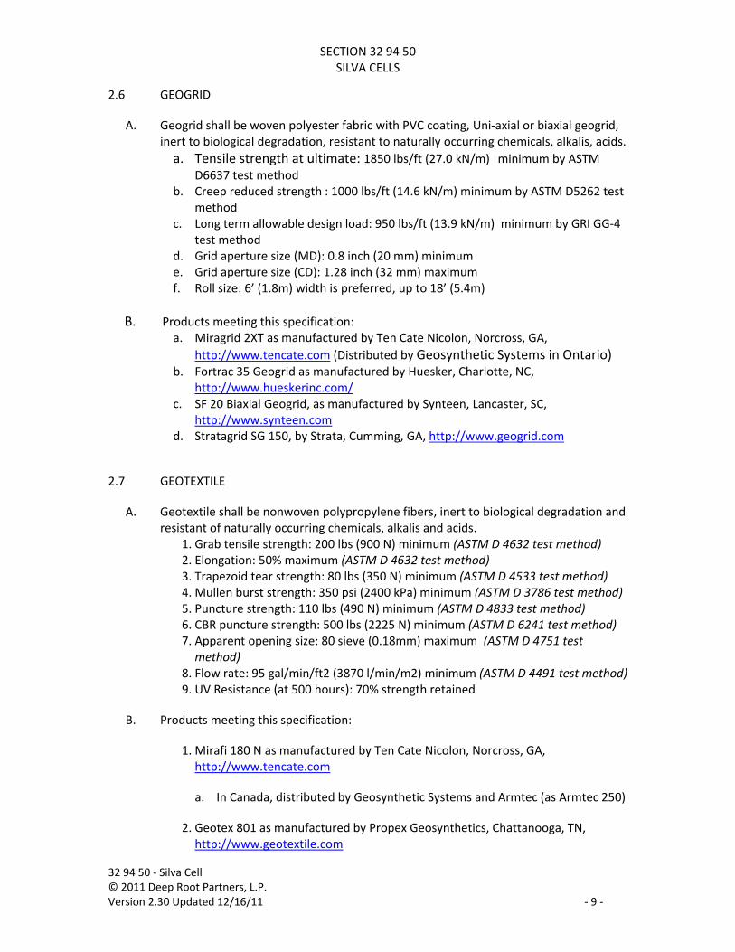
2.6 GEOGRID
A. Geogrid shall be woven polyester fabric with PVC coating, Uni‐axial or biaxial geogrid, inert to biological degradation, resistant to naturally occurring chemicals, alkalis, acids. a. Tensile strength at ultimate: 1850 lbs/ft (27.0 kN/m) minimum by ASTM
D6637 test method b. Creep reduced strength : 1000 lbs/ft (14.6 kN/m) minimum by ASTM D5262 test
method c. Long term allowable design load: 950 lbs/ft (13.9 kN/m) minimum by GRI GG‐4
test method d. Grid aperture size (MD): 0.8 inch (20 mm) minimum e. Grid aperture size (CD): 1.28 inch (32 mm) maximum f. Roll size: 6’ (1.8m) width is preferred, up to 18’ (5.4m)
B. Products meeting this specification: a. Miragrid 2XT as manufactured by Ten Cate Nicolon, Norcross, GA,
http://www.tencate.com (Distributed by Geosynthetic Systems in Ontario) b. Fortrac 35 Geogrid as manufactured by Huesker, Charlotte, NC,
http://www.hueskerinc.com/ c. SF 20 Biaxial Geogrid, as manufactured by Synteen, Lancaster, SC,
http://www.synteen.com d. Stratagrid SG 150, by Strata, Cumming, GA, http://www.geogrid.com
2.7 GEOTEXTILE
A. Geotextile shall be nonwoven polypropylene fibers, inert to biological degradation and resistant of naturally occurring chemicals, alkalis and acids.
1. Grab tensile strength: 200 lbs (900 N) minimum (ASTM D 4632 test method) 2. Elongation: 50% maximum (ASTM D 4632 test method) 3. Trapezoid tear strength: 80 lbs (350 N) minimum (ASTM D 4533 test method) 4. Mullen burst strength: 350 psi (2400 kPa) minimum (ASTM D 3786 test method) 5. Puncture strength: 110 lbs (490 N) minimum (ASTM D 4833 test method) 6. CBR puncture strength: 500 lbs (2225 N) minimum (ASTM D 6241 test method) 7. Apparent opening size: 80 sieve (0.18mm) maximum (ASTM D 4751 test method)
8. Flow rate: 95 gal/min/ft2 (3870 l/min/m2) minimum (ASTM D 4491 test method) 9. UV Resistance (at 500 hours): 70% strength retained
B. Products meeting this specification:
1. Mirafi 180 N as manufactured by Ten Cate Nicolon, Norcross, GA, http://www.tencate.com
a. In Canada, distributed by Geosynthetic Systems and Armtec (as Armtec 250)
2. Geotex 801 as manufactured by Propex Geosynthetics, Chattanooga, TN, http://www.geotextile.com
SECTION 32 94 50 SILVA CELLS
32 94 50 ‐ Silva Cell © 2011 Deep Root Partners, L.P. Version 2.30 Updated 12/16/11 ‐ 10 ‐
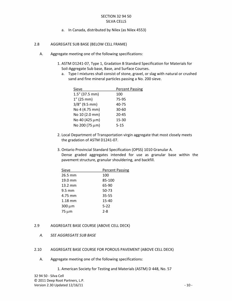
a. In Canada, distributed by Nilex (as Nilex 4553)
2.8 AGGREGATE SUB BASE (BELOW CELL FRAME)
A. Aggregate meeting one of the following specifications:
1. ASTM D1241‐07, Type 1, Gradation B Standard Specification for Materials for Soil‐Aggregate Sub base, Base, and Surface Courses. a. Type I mixtures shall consist of stone, gravel, or slag with natural or crushed
sand and fine mineral particles passing a No. 200 sieve.
Sieve Percent Passing 1.5" (37.5 mm) 100 1” (25 mm) 75‐95 3/8” (9.5 mm) 40‐75 No 4 (4.75 mm) 30‐60 No 10 (2.0 mm) 20‐45 No 40 (425 μm) 15‐30 No 200 (75 μm) 5‐15
2. Local Department of Transportation virgin aggregate that most closely meets the gradation of ASTM D1241‐07.
3. Ontario Provincial Standard Specification (OPSS) 1010 Granular A. Dense graded aggregates intended for use as granular base within the pavement structure, granular shouldering, and backfill.
Sieve Percent Passing 26.5 mm 100 19.0 mm 85‐100 13.2 mm 65‐90 9.5 mm 50‐73 4.75 mm 35‐55 1.18 mm 15‐40 300 μm 5‐22 75 μm 2‐8
2.9 AGGREGATE BASE COURSE (ABOVE CELL DECK)
A. SEE AGGREGATE SUB BASE
2.10 AGGREGATE BASE COURSE FOR POROUS PAVEMENT (ABOVE CELL DECK)
A. Aggregate meeting one of the following specifications:
1. American Society for Testing and Materials (ASTM) D 448, No. 57

SECTION 32 94 50 SILVA CELLS
32 94 50 ‐ Silva Cell © 2011 Deep Root Partners, L.P. Version 2.30 Updated 12/16/11 ‐ 11 ‐
Sieve Percent Passing 1.5” (37.5 mm) 100 1” (25mm) 95‐100 1/2” (12.5 mm) 25‐60 No 4 (4.75 mm) 0‐10 No 8 (2.36 mm) 0‐5
2.11 SETTING BED FOR UNIT PAVERS (ABOVE CELL DECK)
A. Aggregate meeting one of the following specifications:
1. American Society for Testing and Materials (ASTM) D 448, No. 8 Sieve Percent Passing 1/2” (12.5 mm) 100 3/8” (9.5mm) 85‐100 No 4 (4.75 mm) 10‐30 No 8 (2.36 mm) 0‐10 No 16 (1.18 mm) 0‐5
2.12 BACKFILL MATERIAL (ADJACENT TO SILVA CELLS):
A. Clean, compactable, coarse grained fill soil meeting the requirements of the Unified Soil Classification system for soil type GW, GP, GC with less than 30% fines, SW, and SC with less than 30% fines. Backfill material shall be free of organic material, trash and other debris, and shall be free of toxic material injurious to plant growth.
B. Submit supplier certificate for material meeting this specification.
2.13 PLANTING SOIL: (See Specification Section 32 94 56 ‐ Planting Soil for Silva Cells)
2.14 ROOT BARRIER
A. Root Barrier shall be DeepRoot; Tree Root Barriers; UB 18‐2, manufactured by DeepRoot Partners, L.P. (Deep Root); 530 Washington Street, San Francisco, CA 94111; 415.781.9700; 800.458.7668; fax 415.781.0191; www.deeproot.com.
B. Material: Black, injection molded panels, 0.080"(2.03mm) wall thickness in modules 24” (61cm) long by 18” (46cm) deep; manufactured with a minimum 50% post‐consumer recycled polypropylene plastic with UV inhibitors; recyclable. Integrated zipper joining system providing for instant assembly by sliding one panel into another.

SECTION 32 94 50 SILVA CELLS
32 94 50 ‐ Silva Cell © 2011 Deep Root Partners, L.P. Version 2.30 Updated 12/16/11 ‐ 12 ‐
PART 3 ‐ EXECUTION
NOTE TO SPECIFICATION EDITOR: The Silva Cell system does not fully meet H‐20 loading until the final paving is installed. No equipment shall be used on top of the Cell system until paving installation has been completed.
3.1 LAYOUT APPROVAL
A. Prior to the start of work, layout and stake the limits of excavation and horizontal and vertical control points sufficient to install the Silva Cells and required drainage features in the correct locations.
3.2 EXCAVATION
A. Excavate to the depths and shapes indicated on the drawings. Base of excavation shall be smooth soil, level and free of lumps or debris.
B. Do not over‐excavate existing soil beside or under the limits of excavation required for the installation. If soil is over‐excavated, install compactable fill material in lifts not more than 8 inches (200 mm) deep and compact to the required density.
C. Confirm that the depth of the excavation is accurate to accommodate the depths and thickness of materials required throughout the extent of the excavation.
D. Confirm that the width and length of the excavation is a minimum of 6 inches (150 mm), in all directions, beyond the edges of the Silva Cells.
3.3 SUBGRADE COMPACTION
A. Check compaction of the subgrade below the Silva Cells and confirm that the subgrade soil is compacted to a minimum of 95% of maximum dry density at optimum moisture content in accordance with ASTM D 698 Standard Proctor Method.
B. Proof compact the subgrade with a minimum of three passes of a suitable vibrating compacting machine or apply other compaction forces as needed to achieve the required subgrade compaction rate.
C. Apply additional compaction forces at optimum water levels.
3.4 INSTALLATION OF GEOTEXTILE OVER SUBGRADE
A. Where indicated on drawings, install geotextile over compacted subgrade.
B. Removal of the geotextile as a standard component of the Silva Cell system must be determined by professional civil or geotechnical engineer.
SECTION 32 94 50 SILVA CELLS
32 94 50 ‐ Silva Cell © 2011 Deep Root Partners, L.P. Version 2.30 Updated 12/16/11 ‐ 13 ‐
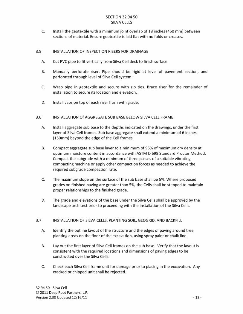
C. Install the geotextile with a minimum joint overlap of 18 inches (450 mm) between sections of material. Ensure geotextile is laid flat with no folds or creases.
3.5 INSTALLATION OF INSPECTION RISERS FOR DRAINAGE
A. Cut PVC pipe to fit vertically from Silva Cell deck to finish surface.
B. Manually perforate riser. Pipe should be rigid at level of pavement section, and perforated through level of Silva Cell system.
C. Wrap pipe in geotextile and secure with zip ties. Brace riser for the remainder of installation to secure its location and elevation.
D. Install caps on top of each riser flush with grade.
3.6 INSTALLATION Of AGGREGATE SUB BASE BELOW SILVA CELL FRAME
A. Install aggregate sub base to the depths indicated on the drawings, under the first layer of Silva Cell frames. Sub base aggregate shall extend a minimum of 6 inches (150mm) beyond the edge of the Cell frames.
B. Compact aggregate sub base layer to a minimum of 95% of maximum dry density at optimum moisture content in accordance with ASTM D 698 Standard Proctor Method. Compact the subgrade with a minimum of three passes of a suitable vibrating compacting machine or apply other compaction forces as needed to achieve the required subgrade compaction rate.
C. The maximum slope on the surface of the sub base shall be 5%. Where proposed grades on finished paving are greater than 5%, the Cells shall be stepped to maintain proper relationships to the finished grade.
D. The grade and elevations of the base under the Silva Cells shall be approved by the landscape architect prior to proceeding with the installation of the Silva Cells.
3.7 INSTALLATION OF SILVA CELLS, PLANTING SOIL, GEOGRID, AND BACKFILL
A. Identify the outline layout of the structure and the edges of paving around tree planting areas on the floor of the excavation, using spray paint or chalk line.
B. Lay out the first layer of Silva Cell frames on the sub base. Verify that the layout is consistent with the required locations and dimensions of paving edges to be constructed over the Silva Cells.
C. Check each Silva Cell frame unit for damage prior to placing in the excavation. Any cracked or chipped unit shall be rejected.

SECTION 32 94 50 SILVA CELLS
32 94 50 ‐ Silva Cell © 2011 Deep Root Partners, L.P. Version 2.30 Updated 12/16/11 ‐ 14 ‐
D. Place frames no less than 1 inch (25 mm) and no more than 3 inches (75 mm) apart at base. In the event that spacing between Cells exceeds 3 inches (75 mm), bridging slab details and methods shall be used to span these gaps.
E. Install Silva Cell frames around, over, or under existing or proposed utility lines as indicated on plans.
F. Where any two adjacent Silva Cell frames must be installed at different elevations, the upper frame shall be supported by aggregate sub base with a maximum slope of 1:1. This may require installation of aggregate sub base within the adjacent lower Cell frame. No two frames shall differ in elevation by more than 15 inches (375 mm).
G. Assure that each frame sits solidly on the surface of the sub base. Frames shall not rock or bend over any stone or other obstruction protruding above the surface of the sub base material. Frames shall not bend into dips in the sub base material. The maximum tolerance for deviations in the plane of the sub base material under the bottom of the horizontal beams of each Silva Cell frame shall be 1/4 inch (6 mm) in 4 feet (1200 mm).
H. Adjust sub base material including larger pieces of aggregate under each frame to provide a solid base of support.
1. Anchor each Silva Cell into sub base with four‐10 inch (250 mm) spikes, driven through the molded holes in the Cell frame base. The purpose of the anchoring system is to maintain cell spacing and layout during the installation of planting soil and backfill.
2. For applications where cells are installed over waterproofed structures, develop a spacing system consistent with requirements of the waterproofing system. Do not use anchoring nails that will come within 6" or less of any waterproofing material.
I. Install the second layer of Silva Cell frames on top of the first layer. Comply with manufacturer’s requirements to correctly register and connect the Cell frames together.
J. Register each frame on top of the lower frame post. Rotate each frame registration arrow in the opposite direction from the frame below to assure that connector tabs firmly connect. Each frame shall be solidly seated on the one below.
K. Build layers as stacks of frames set one directly over the other. Do not set any frame half on one Cell frame below and half on an adjacent frame.
L. Install Strongbacks on top of the Silva Cell frames prior to installing planting soil and backfill.
1. Strongbacks are required only during the installation and compaction of the planting soil and backfill.
2. Strongbacks should be moved as the work progresses across the installation.
SECTION 32 94 50 SILVA CELLS
32 94 50 ‐ Silva Cell © 2011 Deep Root Partners, L.P. Version 2.30 Updated 12/16/11 ‐ 15 ‐
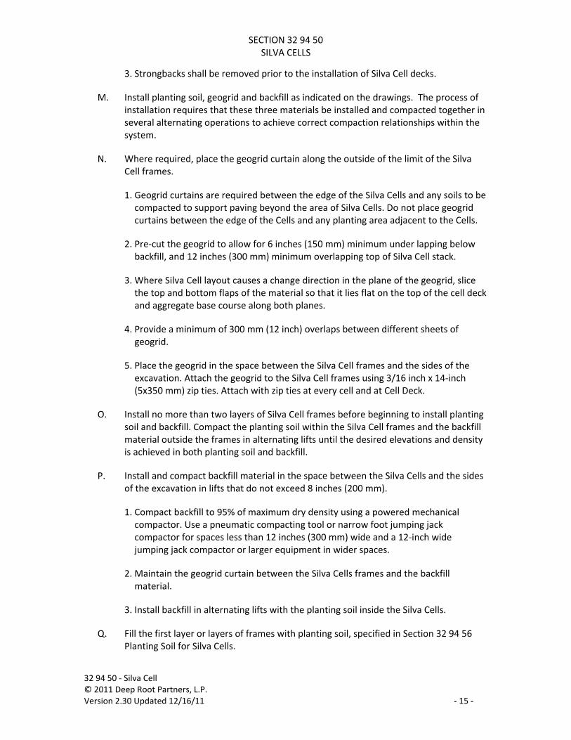
3. Strongbacks shall be removed prior to the installation of Silva Cell decks.
M. Install planting soil, geogrid and backfill as indicated on the drawings. The process of installation requires that these three materials be installed and compacted together in several alternating operations to achieve correct compaction relationships within the system.
N. Where required, place the geogrid curtain along the outside of the limit of the Silva Cell frames.
1. Geogrid curtains are required between the edge of the Silva Cells and any soils to be compacted to support paving beyond the area of Silva Cells. Do not place geogrid curtains between the edge of the Cells and any planting area adjacent to the Cells.
2. Pre‐cut the geogrid to allow for 6 inches (150 mm) minimum under lapping below backfill, and 12 inches (300 mm) minimum overlapping top of Silva Cell stack.
3. Where Silva Cell layout causes a change direction in the plane of the geogrid, slice the top and bottom flaps of the material so that it lies flat on the top of the cell deck and aggregate base course along both planes.
4. Provide a minimum of 300 mm (12 inch) overlaps between different sheets of geogrid.
5. Place the geogrid in the space between the Silva Cell frames and the sides of the excavation. Attach the geogrid to the Silva Cell frames using 3/16 inch x 14‐inch (5x350 mm) zip ties. Attach with zip ties at every cell and at Cell Deck.
O. Install no more than two layers of Silva Cell frames before beginning to install planting soil and backfill. Compact the planting soil within the Silva Cell frames and the backfill material outside the frames in alternating lifts until the desired elevations and density is achieved in both planting soil and backfill.
P. Install and compact backfill material in the space between the Silva Cells and the sides of the excavation in lifts that do not exceed 8 inches (200 mm).
1. Compact backfill to 95% of maximum dry density using a powered mechanical compactor. Use a pneumatic compacting tool or narrow foot jumping jack compactor for spaces less than 12 inches (300 mm) wide and a 12‐inch wide jumping jack compactor or larger equipment in wider spaces.
2. Maintain the geogrid curtain between the Silva Cells frames and the backfill material.
3. Install backfill in alternating lifts with the planting soil inside the Silva Cells.
Q. Fill the first layer or layers of frames with planting soil, specified in Section 32 94 56 Planting Soil for Silva Cells.

SECTION 32 94 50 SILVA CELLS
32 94 50 ‐ Silva Cell © 2011 Deep Root Partners, L.P. Version 2.30 Updated 12/16/11 ‐ 16 ‐
1. Bring planting soil to the site using equipment and methods that do not overly mix and further damage soil peds within the soil mix. Soil mixes shall not be blown or pumped into the Cells using soil blowing equipment.
2. Install in lifts that do not exceed 16 inches (400 mm). Lightly compact the soil inside the frames at each lift to remove air pockets and settle the soil within the frames.
3. Do not compact greater than 80% of maximum dry density. Check the soil compaction with a penetrometer or densiometer to achieve similar compaction levels provided in the mock up.
4. If the planting soil becomes overly compacted, remove the soil and reinstall. Use hand tools or other equipment that does not damage the Silva Cell frames.
5. Do not walk directly on horizontal beams of the frames.
6. Work soil under the horizontal frame beams of the second level of Cell frames and between columns eliminating air pockets and voids. Fill each frame such that there is a minimum of 10 inches (250 mm) of soil over the top of horizontal frame beams before beginning compaction.
7. The top 1‐2 inches (25‐50 mm) of each frame post should remain exposed above the soil to allow the placement of the next frame or deck.
R. After the first two layers of Silva Cell frames have been installed, filled with planting soil and backfilled, proceed to install the third layer, if required, of Silva Cells frames. Comply with manufacturer’s requirements to correctly register and connect the Cell frames together.
S. Remove the strongbacks. Sweep any soil from tops before adding the next layer of frames.
T. Register each frame on top of the lower frame post. Rotate each frame registration arrow in the opposite direction from the frame below to assure that connector tabs firmly connect. Each frame shall be solidly seated on the one below.
U. Build layers as stacks of frames set one directly over the other. Do not set any frame half on one Cell frame below and half on an adjacent frame.
V. Install Strongbacks on top of third layer of Silva Cells.
W. Continue to install and compact the planting soil within the Silva Cell frames and the backfill material outside the frames in alternating lifts until the desired elevations and density is achieved in both soils.
X. When using compost, add a final layer of planting soil as required to bring the planting soil level to not more than 3 inches (75 mm) below the bottom of the Silva Cell Deck when installed. When using air space rather than compost, the planting soil shall be
SECTION 32 94 50 SILVA CELLS
32 94 50 ‐ Silva Cell © 2011 Deep Root Partners, L.P. Version 2.30 Updated 12/16/11 ‐ 17 ‐
brought to level not more than 1 inch (25 mm) below the bottom of the Silva Cell Deck when installed.
Y. Obtain final approval by the landscape architect of soil installation prior to installation of the Silva Cell deck.
Z. Remove Strongbacks after planting soil and backfill has been compacted to the top of the entire set of Silva Cells.
AA. Install 3 inches (75 mm) of compost, or leave 1‐inch (25 mm) air space, below Silva Cell Deck as indicated on the drawings.
3.8 IRRIGATION AND WATER HARVESTING SYSTEM INSTALLATION
A. Install irrigation and water harvesting system per project specifications.
NOTE TO SPECIFICATION EDITOR: Water is critical to the success of the Silva Cell system. Coordinate with any required irrigation installations. Irrigation should be installed within the entire soil system, not only at the tree opening.
3.9 SILVA CELL DECK INSTALLATION
A. Install the Silva Cell Decks over the top of each frame stack. Clean dirt from the tops of the Silva Cell frame columns. Register the deck and make connections as recommended by the manufacturer to secure the deck to the top of the Silva Cell Frame. Secure each deck at the four corners with screw fasteners as recommended by the manufacturer. Assure that each deck is seated firmly on the frame top with all connectors attached.
B. Install and compact remaining backfill material such that the soil outside the limits of the Silva Cells is flush with the top of the installed deck.
3.10 INSTALLATION OF GEOTEXTILE, GEOGRID, INSPECTION RISER FOR SOIL, AND AGGREGATE OVER THE DECK
A. Overlap geogrid from the sides of the Silva Cells over the top of the Silva Cell Decks, with minimum of 12 inches (300mm) overlap.
B. Place geotextile over the top of the deck and where indicated on the drawings, extending beyond the outside edge of the excavation by at least 18 inches (450 mm). Any joints must be overlapped by a minimum of 18 inches (450 mm).
C. Install inspection risers for soil above geotextile as indicated on drawings. 1. Cut PVC pipe to fit vertically from Silva Cell deck to finish surface. 2. Align riser with slots in Silva Cell deck.

SECTION 32 94 50 SILVA CELLS
32 94 50 ‐ Silva Cell © 2011 Deep Root Partners, L.P. Version 2.30 Updated 12/16/11 ‐ 18 ‐
3. Wrap pipe in geotextile and secure with zip ties. Cut geotextile to overlap deck minimum 12”.
4. Cut geotextile inside the pipe to allow access. Do not cut or otherwise damage Silva Cell deck.
5. Install caps on top of each riser flush with final paving surface.
D. Install the aggregate base course (including aggregate setting bed if installing unit pavers) over the geotextile immediately after completing the installation of the fabrics and inspection risers. Work the aggregate from one side of the deck to the other to assure that the fabric and aggregate conforms to the cell deck contours. Do not apply aggregate in several positions at the same time.
1. Aggregate base course shall be a minimum of 4 inches (100mm) thick under pored in place concrete paving.
2. Aggregate base course shall be a minimum of 12 inches (300mm) thick under unit pavers, asphalt paving, or porous paving.
E. Load the aggregate from equipment that is outside the limits of the excavated area. Work over material already in place.
F. For large or confined areas, where aggregate cannot easily be placed from the edges of the excavated area, obtain approval for the installation procedure and types of equipment to be used in the installation from the Silva Cell manufacturer.
G. Compact aggregate base course(s) in lifts not to exceed 6" in depth, to 95% of maximum dry density. Utilize a roller or plate compactor with a maximum weight of 1000 pounds. Make sufficient passes with the compacting equipment to attain the required compaction.
3.11 INSTALLATION OF PAVING ABOVE THE SILVA CELL SYSTEM
A. Place paving material over Silva Cell system per project specifications. Take care when placing paving or other backfill on top of Silva Cell system not to damage the system components.
B. Turn down edge of all concrete paving to Cell deck along the edges of all planting areas to retain the aggregate base course.
C. When paving is a unit paver or other flexible material, provide a concrete curb under the paving at the edge of the Silva Cell deck to retain the aggregate base course material.
NOTE TO SPECIFICATION EDITOR: Concrete curbs are necessary within the Silva Cell system along all planting areas and tree openings in order to retain the aggregate base course from migrating into the planting soil. This must be coordinated with project details.
SECTION 32 94 50 SILVA CELLS
32 94 50 ‐ Silva Cell © 2011 Deep Root Partners, L.P. Version 2.30 Updated 12/16/11 ‐ 19 ‐
3.12 INSTALLATION OF BRIDGING SLABS (WHERE APPLICABLE)
A. Bridging slabs are to be used in locations where spacing larger than 3 inches (75 mm) is necessary between Silva Cell frames.
B. Replace aggregate base course material with a minimum 4 inch (100 mm) concrete slab beneath paving. The paving shall extend beyond the gap between Cells at a minimum of 24 inches (610 mm).
C. If spacing (gap) between Cells is larger than 12 inches (300 mm), the concrete slab must be increased to 6 inch (150 mm) thickness. If spacing (gap) between Cells is larger than 18 inches (450 mm), steel reinforcing shall be added to the slab. Reinforcing is to be designed by the project structural engineer. In no case shall the space between Cells be greater than 30 inches (750 mm).
3.13 INSTALLATION OF ROOT BARRIERS
A. Install root barrier in accord with manufacturer's reviewed installation instructions.
3.14 INSTALLATION OF PLANTING SOIL WITHIN THE TREE PLANTING AREA
A. Prior to planting trees, install additional planting soil, to the depths indicated, within the tree opening adjacent to paving supported by Silva Cells.
B. Remove all rubble, debris, dust and silt from the top of the planting soil that may have accumulated after the initial installation of the planting soil within the Silva Cells.
C. Assure that the planting soil under the tree root ball is compacted for the entire soil depth to 85‐90% to prevent settlement of the root ball.
D. The planting soil within the tree opening shall be the same soil as in the adjacent Silva Cells.
E. Cover the planting soil finished grade with 2 inches (50 mm) of mulch, or as defined in Project specifications.
3.15 REPAIR OF CUT GEOTEXTILE
A. In the event that any geotextile over subgrades or the Silva Cell decks must be cut during or after installation, repair the seam with a second piece of geotextile that overlaps the edges of the cut by a minimum of 12‐inches in all directions prior to adding aggregate material.
SECTION 32 94 50 SILVA CELLS
32 94 50 ‐ Silva Cell © 2011 Deep Root Partners, L.P. Version 2.30 Updated 12/16/11 ‐ 20 ‐
3.16 PROTECTION
A. Ensure that all construction traffic is kept away from the limits of the Silva Cells until the final surface materials are in place. No vehicles shall drive directly on the Silva Cell deck or aggregate base course.
B. Provide fencing and other barriers to keep vehicles from entering into the area with Silva Cell supported pavement.
C. Maintain a minimum of 4 inches (100 mm) of aggregate base course over the geotextile material during construction.
D. When vehicle must cross Silva Cells that does not have final paving surfaces installed, use construction mats designed to distribute vehicle loads to levels that would be expected at the deck surface once final paving has been installed. Use only low impact track vehicles with a maximum surface pressure under the vehicle of 4 pounds per square inch, on top of the mats over Silva Cells prior to the installation of final paving.
3.17 CLEAN UP
A. Perform cleanup during the installation of work and upon completion of the work. Maintain the site free of soil and sediment, free of trash and debris. Remove from site all excess soil materials, debris, and equipment. Repair any damage to adjacent materials and surfaces resulting from installation of this work.
END OF SECTION
SECTION 32 94 50 SILVA CELLS
32 94 50 ‐ Silva Cell © 2011 Deep Root Partners, L.P. Version 2.30 Updated 12/16/11 ‐ 21 ‐
Submittal Checklist for Reference Only Contractor shall provide submittals required to the landscape architect for review and approval. The Submittal process may take up to two months prior to installation of the Silva Cell system and should be executed as soon as possible after the contract is awarded. All testing will be at the expense of the Contractor.
1.4 Compaction testing results
Testing of mock up results Compaction testing log
1.5 Schedule of work and coordination with other trades
Required schedules Name and work experience of field supervisor
1.6 Installer qualifications
List of completed projects of similar scale Name and work experience of field supervisor
2.1 Silva Cells
Manufacturers product literature Manufacturers product warranty Silva Cell manufacturer's letter of review and approval of the project, plans, details
and specifications for compliance with product installation requirements.
2.2 Anchoring Spikes Manufacturers product literature
2.3 Solid and perforated drain lines
Manufacturers product literature
2.4 Inspection risers and caps Manufacturers product literature
2.5 Geogrid
Manufacturers product literature
2.6 Geotextile Manufacturers product literature
2.7 Aggregate sub base
Manufacturers product literature and certificate with particle size distribution data Compaction testing results
2.8 Aggregate base course
Supplier certificate for material meeting this specification including particle size distribution data
Compaction testing results

SECTION 32 94 50 SILVA CELLS
32 94 50 ‐ Silva Cell © 2011 Deep Root Partners, L.P. Version 2.30 Updated 12/16/11 ‐ 22 ‐
2.11 Backfill Material
Compaction testing results Supplier certificate for material meeting this specification.
2.13 Root barrier
Manufacturers product literature