section 3.7 stormwater filtering systems
TRANSCRIPT
3.7 Filtering Systems
129
3.7 Filtering Systems
Definition. Practices that capture and temporarily store the design storm volume and pass it
through a filter bed of sand media. Filtered runoff may be collected and returned to the
conveyance system or allowed to partially infiltrate into the soil. Design variants include:
F-1 Non-structural sand filter
F-2 Surface sand filter
F-3 Three-chamber underground sand filter
F-4 Perimeter sand filter
Stormwater filters are a useful practice to treat stormwater runoff from small, highly impervious
sites. Stormwater filters capture, temporarily store, and treat stormwater runoff by passing it
through an engineered filter media, collecting the filtered water in an underdrain, and then
returning it back to the storm drainage system. The filter consists of two chambers: the first is
devoted to settling and the second serves as a filter bed consisting of a sand filter media.
Stormwater filters are a versatile option because they consume very little surface land and have
few site restrictions. They provide moderate pollutant removal performance at small sites where
space is limited. However, filters have no retention capability, so designers should consider using
up-gradient retention practices, which have the effect of decreasing the design storm volume and
size of the filtering practices. Filtering practices are also suitable to provide special treatment at
designated stormwater hotspots. A list of potential stormwater hotspots operations can be found
in Appendix P.
Filtering systems are typically not to be designed to provide stormwater detention (Qp2, Qp15),
but they may be in some circumstances. Filtering practices are generally combined with separate
facilities to provide this type of control. However, the three-chamber underground sand filter can
be modified by expanding the first or settling chamber, or adding an extra chamber between the
filter chamber and the clear well chamber to handle the detention volume, which is subsequently
discharged at a predetermined rate through an orifice and weir combination.
Chapter 3 Stormwater Best Management Practices (BMPs)
130
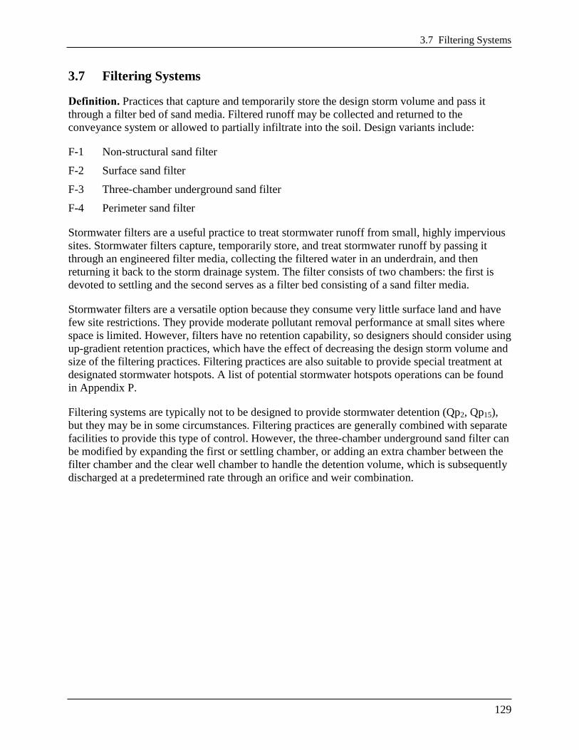
Figure 3.21 Typical schematic for a surface sand filter (F-2).
Note: Material specifications are indicated in Table 3.28.

3.7 Filtering Systems
131
Figure 3.22 Part A – Example of a three-chamber underground sand filter (F-3) for separate sewer
areas. Note: Material specifications are indicated in Table 3.28.
Chapter 3 Stormwater Best Management Practices (BMPs)
132
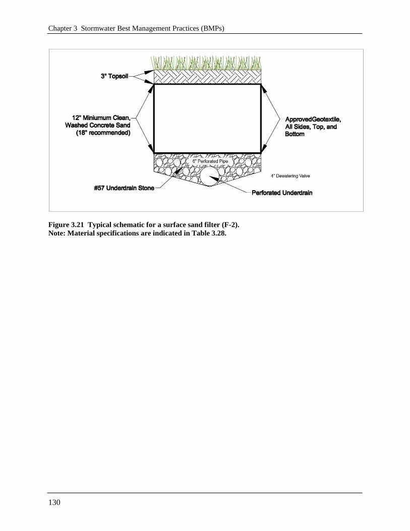
Figure 3.23 Part B – Example of a three-chamber underground sand filter (F-3) for separate sewer
areas. Note: Material specifications are indicated in Table 3.28.

3.7 Filtering Systems
133
Figure 3.24 Part C – Example of a three-chamber underground sand filter (F-3) for separate sewer
areas. Note: Material specifications are indicated in Table 3.28.

Chapter 3 Stormwater Best Management Practices (BMPs)
134
Figure 3.25 Part A – Example of a three-chamber underground sand filter (F-3) for combined
sewer areas. Note: Material specifications are indicated in Table 3.28.

3.7 Filtering Systems
135
Figure 3.26 Part B – Example of a three-chamber underground sand filter (F-3) for combined
sewer areas. Note: Material specifications are indicated in Table 3.28.
Chapter 3 Stormwater Best Management Practices (BMPs)
136
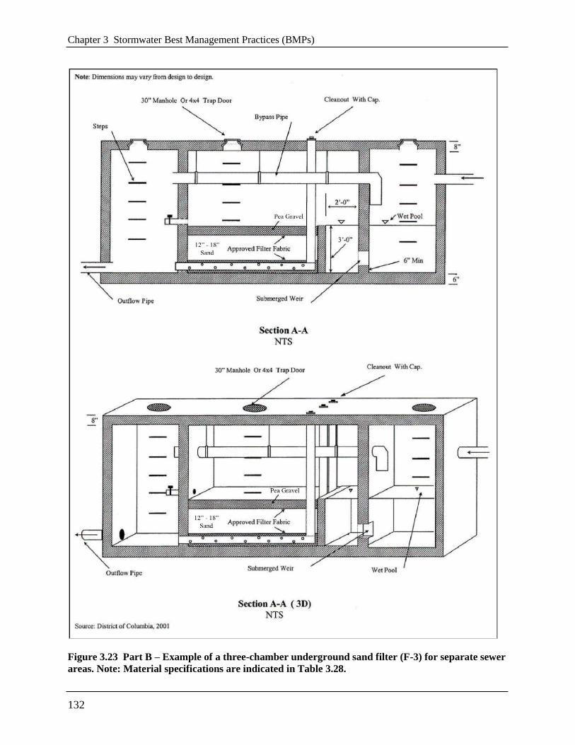
Figure 3.27 Part C – Example of a three-chamber underground sand filter (F-3) for combined
sewer areas. Note: Material specifications are indicated in Table 3.28.

3.7 Filtering Systems
137
Figure 3.28 Example of a perimeter sand filter (F-4).
Note: Material specifications are indicated in Table 3.28.

Chapter 3 Stormwater Best Management Practices (BMPs)
138
3.7.1 Filtering Feasibility Criteria
Stormwater filters can be applied to most types of urban land. They are not always cost-effective,
given their high unit cost and small area served, but there are situations where they may clearly
be the best option for stormwater treatment (e.g., hotspot runoff treatment, small parking lots,
ultra-urban areas, etc.). The following criteria apply to filtering practices:
Available Hydraulic Head. The principal design constraint for stormwater filters is available
hydraulic head, which is defined as the vertical distance between the top elevation of the filter
and the bottom elevation of the existing storm drain system that receives its discharge. The head
required for stormwater filters ranges from 2 to 10 feet, depending on the design variant. It is
difficult to employ filters in extremely flat terrain, since they require gravity flow through the
filter. The only exception is the perimeter sand filter, which can be applied at sites with as little
as 2 feet of head.
Depth to Water Table and Bedrock. The designer must assure a standard separation distance
of at least 2 feet between the seasonally high groundwater table and/or bedrock layer and the
bottom invert of the filtering practice.
Contributing Drainage Area. Filters are best applied on small sites where the contributing
drainage (CDA) area is as close to 100 percent impervious as possible in order to reduce the risk
that eroded sediment will clog the filter. If the CDA is pervious, then the vegetation must be
dense and stable. Turf is acceptable (see Section 3.7.5 Filtering Landscaping Criteria). A
maximum CDA of 5 acres is recommended for surface sand filters, and a maximum CDA of 2
acres is recommended for perimeter or underground filters. Filters have been used on larger
drainage areas in the past, but greater clogging problems have typically resulted. The one-
chamber sand filter is only applicable for impervious area less than 10,000 ft2 (1/4 acre).
Space Required. The amount of space required for a filter practice depends on the design
variant selected. Surface sand filters typically consume about 2 to 3 percent of the CDA, while
perimeter sand filters typically consume less than 1 percent. Underground stormwater filters
generally consume no surface area except their manholes.
Land Use. As noted above, filters are particularly well suited to treat runoff from stormwater
hotspots and smaller parking lots. Other applications include redevelopment of commercial sites
or when existing parking lots are renovated or expanded. Filters can work on most commercial,
industrial, institutional, or municipal sites and can be located underground if surface area is not
available.
Site Topography. Filters shall not be located on slopes greater than 6 percent.
Utilities. All utilities shall have a minimum 5-foot, horizontal clearance from the filtering
practice.
Facility Access. All filtering systems shall be located in areas where they are accessible for
inspection and for maintenance (by vacuum trucks).

3.7 Filtering Systems
139
Soils. Soil conditions do not constrain the use of filters. At least one soil boring must be taken at
a low point within the footprint of the proposed filtering practice to establish the water table and
bedrock elevations and evaluate soil suitability. A geotechnical investigation is required for all
underground stormwater best management practices (BMPs), including underground filtering
systems. Geotechnical testing requirements are outlined in Appendix O.
3.7.2 Filtering Conveyance Criteria
Most filtering practices are designed as off-line systems so that all flows enter the filter storage
chamber until it reaches capacity, at which point larger flows are then diverted or bypassed
around the filter to an outlet chamber and are not treated. Runoff from larger storm events must
be bypassed using an overflow structure or a flow splitter. Claytor and Schueler (1996) and ARC
(2001) provide design guidance for flow splitters for filtering practices.
Some underground filters will be designed and constructed as on-line BMPs. In these cases,
designers must indicate how the device will safely pass larger storm events (e.g., the 15-year
event) to a stabilized water course without resuspending or flushing previously trapped material.
All stormwater filters must be designed to drain or dewater within 72 hours after a storm event to
reduce the potential for nuisance conditions.
3.7.3 Filtering Pretreatment Criteria
Adequate pretreatment is needed to prevent premature filter clogging and ensure filter longevity.
Dry or wet pretreatment shall be provided prior to filter media. Pretreatment devices are subject
to the following criteria:
Sedimentation chambers are typically used for pretreatment to capture coarse sediment
particles before they reach the filter bed.
Sedimentation chambers may be wet or dry but must be sized to accommodate at least 25
percent of the total design storm volume (inclusive).
Sediment chambers should be designed as level spreaders such that inflows to the filter bed
have near zero velocity and spread runoff evenly across the bed.
Non-structural and surface sand filters may use alternative pretreatment measures, such as a
grass filter strip, forebay, gravel diaphragm, check dam, level spreader, or a combination of
these. The grass filter strip must be a minimum length of 15 feet and have a slope of 3
percent or less. The check dam may be wooden or concrete and must be installed so that it
extends only 2 inches above the filter strip and has lateral slots to allow runoff to be evenly
distributed across the filter surface. Alternative pretreatment measures must contain a non-
erosive flow path that distributes the flow evenly over the filter surface. If a forebay is used,
it must be designed to accommodate at least 25 percent of the total design storm volume
(inclusive).

Chapter 3 Stormwater Best Management Practices (BMPs)
140
3.7.4 Filtering Design Criteria
Detention time. All filter systems must be designed to drain the design storm volume from the
filter chamber within 72 hours after each rainfall event.
Structural Requirements. If a filter will be located underground or experience traffic loads, a
licensed structural engineer must certify the structural integrity of the design.
Geometry. Filters are gravity flow systems that normally require 2 to 5 feet of driving head to
push the water through the filter media through the entire maintenance cycle; therefore, sufficient
vertical clearance between the inverts of the inflow and outflow pipes is required.
Type of Filter Media. The normal filter media consists of clean, washed AASHTO M-6/ASTM
C-33 medium aggregate concrete sand with individual grains between 0.02 and 0.04 inches in
diameter.
Depth of Filter Media. The depth of the filter media plays a role in how quickly stormwater
moves through the filter bed and how well it removes pollutants. The recommended filter bed
depth is 18 inches. An absolute minimum filter bed depth of 12 inches above underdrains is
required; although, designers should note that specifying the minimum depth of 12 inches will
incur a more intensive maintenance schedule and possibly result in more costly maintenance.
Underdrain and Liner. Stormwater filters are normally designed with an impermeable liner and
underdrain system that meet the criteria provided in Table 3.28 below.
Underdrain Stone. The underdrain should be covered by a minimum 6-inch gravel layer
consisting of clean, double washed No. 57 stone.
Type of Filter. There are several design variations of the basic filter that enable designers to use
filters at challenging sites or to improve pollutant removal rates. The choice of which filter
design to apply depends on available space, hydraulic head, and the level of pollutant removal
desired. In ultra-urban situations where surface space is at a premium, underground sand filters
are often the only design that can be used. Surface and perimeter filters are often a more
economical choice when adequate surface area is available. The most common design variants
include the following:
Non-Structural Sand Filter (F-1). The non-structural sand filter is applied to sites less than
2 acres in size and is very similar to a bioretention practice (see Section 3.6 Bioretention),
with the following exceptions:
The bottom is lined with an impermeable liner and always has an underdrain.
The surface cover is sand, turf, or pea gravel.
The filter media is 100 percent sand.
The filter surface is not planted with trees, shrubs, or herbaceous materials.
The filter has two cells, with a dry or wet sedimentation chamber preceding the sand filter
bed.

3.7 Filtering Systems
141
The non-structural sand filter is the least expensive filter option for treating hotspot runoff.
The use of bioretention areas is generally preferred at most other sites.
Surface Sand Filter (F-2). The surface sand filter is designed with both the filter bed and
sediment chamber located at ground level. The most common filter media is sand; however, a
peat/sand mixture may be used to increase the removal efficiency of the system. In most
cases, the filter chambers are created using precast or cast-in-place concrete. Surface sand
filters are normally designed to be off-line facilities, so that only the desired design volume is
directed to the filter for treatment. However, in some cases they can be installed on the
bottom of a Dry Extended Detention (ED) Pond (see Section 3.9 Open Channel Systems).
Underground Sand Filter. The underground sand filter is modified to install the filtering
components underground and is often designed with an internal flow splitter or overflow
device that bypasses runoff from larger stormwater events around the filter. Underground
sand filters are expensive to construct, but they consume very little space and are well suited
to ultra-urban areas.
Three-Chamber Underground Sand Filter (F-3). The three-chamber underground sand
filter is a gravity flow system. The facility may be precast or cast-in-place. The first chamber
acts as a pretreatment facility removing any floating organic material such as oil, grease, and
tree leaves. It should have a submerged orifice leading to a second chamber, and it should be
designed to minimize the energy of incoming stormwater before the flow enters the second
chamber (i.e., filtering or processing chamber).
The second chamber is the filtering or processing chamber. It should contain the filter
material consisting of gravel and sand and should be situated behind a weir. Along the
bottom of the structure should be a subsurface drainage system consisting of a parallel
perforated PVC pipe system in a stone bed. A dewatering valve should be installed at the top
of the filter layer for safety release in cases of emergency. A bypass pipe crossing the second
chamber to carry overflow from the first chamber to the third chamber is required.
The third chamber is the discharge chamber. It should also receive the overflow from the first
chamber through the bypass pipe when the storage volume is exceeded.
Water enters the first chamber of the system by gravity or by pumping. This chamber
removes most of the heavy solid particles, floatable trash, leaves, and hydrocarbons. Then the
water flows to the second chamber and enters the filter layer by overtopping a weir. The
filtered stormwater is then picked up by the subsurface drainage system that empties it into
the third chamber.
Whenever there is insufficient hydraulic head for a three-chamber underground sand filter, a
well pump may be used to discharge the effluent from the third chamber into the receiving
storm or combined sewer. For three-chamber sand filters in combined-sewer areas, a water
trap shall be provided in the third chamber to prevent the back flow of odorous gas.
Perimeter Sand Filter (F-74). The perimeter sand filter also includes the basic design
elements of a sediment chamber and a filter bed. The perimeter sand filter typically consists
of two parallel trenches connected by a series of overflow weir notches at the top of the
partitioning wall, which allows water to enter the second trench as sheet flow. The first
trench is a pretreatment chamber removing heavy sediment particles and debris. The second
trench consists of the sand filter layer. A subsurface drainage pipe must be installed at the

Chapter 3 Stormwater Best Management Practices (BMPs)
142
bottom of the second chamber to facilitate the filtering process and convey filter water into a
receiving system.
In this design, flow enters the system through grates, usually at the edge of a parking lot. The
perimeter sand filter is usually designed as an on-line practice (i.e., all flows enter the
system), but larger events bypass treatment by entering an overflow chamber. One major
advantage of the perimeter sand filter design is that it requires little hydraulic head and is
therefore a good option for sites with low topographic relief.
Surface Cover. The surface cover for non-structural and surface sand filters should consist of a
3-inch layer of topsoil on top of the sand layer. The surface may also have pea gravel inlets in the
topsoil layer to promote filtration. The pea gravel may be located where sheet flow enters the
filter, around the margins of the filter bed, or at locations in the middle of the filter bed.
Underground sand filters should have a pea gravel layer on top of the sand layer. The pea gravel
helps to prevent bio-fouling or blinding of the sand surface.
Maintenance Reduction Features. The following maintenance issues should be addressed
during filter design to reduce future maintenance problems:
Observation Wells and Cleanouts. Non-structural and surface sand filters must include an
observation well consisting of a 6-inch diameter non-perforated PVC pipe fitted with a
lockable cap. It should be installed flush with the ground surface to facilitate periodic
inspection and maintenance. In most cases, a cleanout pipe will be tied into the end of all
underdrain pipe runs. The portion of the cleanout pipe/observation well in the underdrain
layer should be perforated. At least one cleanout pipe must be provided for every 2000
square feet of filter surface area.
Access. Good maintenance access is needed to allow crews to perform regular inspections
and maintenance activities. ―Sufficient access‖ is operationally defined as the ability to get a
vacuum truck or similar equipment close enough to the sedimentation chamber and filter to
enable cleanouts. Direct maintenance access shall be provided to the pretreatment area and
the filter bed. For underground structures, sufficient headroom for maintenance should be
provided. A minimum head space of 5 feet above the filter is recommended for maintenance
of the structure. However, if 5 feet headroom is not available, manhole access must be
installed.
Manhole Access (for underground filters). Access to the headbox and clearwell of
Underground Filters must be provided by manholes at least 30 inches in diameter, along with
steps to the areas where maintenance will occur.
Visibility. Stormwater filters should be clearly visible at the site so inspectors and
maintenance crews can easily find them. Adequate signs or markings must be provided at
manhole access points for Underground Filters.
Confined Space Issues. Underground filters are often classified as a confined space.
Consequently, special OSHA rules apply, and training may be needed to protect the workers
that access them. These procedures often involve training about confined space entry,
venting, and the use of gas probes.

3.7 Filtering Systems
143
Filter Material Specifications. The basic material specifications for filtering practices that
utilize sand as a filter media are outlined in Table 3.28.
Table 3.28 Filtering Practice Material Specifications
Material Specification
Surface Cover
Non-structural and surface sand filters: 3-inch layer of topsoil on top of the sand
layer. The surface may also have pea gravel inlets in the topsoil layer to
promote filtration.
Underground sand filters: Clean, double washed No. 57 stone on top of the sand
layer.
Sand Clean AASHTO M-6/ASTM C-33 medium aggregate concrete sand with a particle
size range of 0.02 to 0.04 inch in diameter.
Geotextile/Filter Fabric An appropriate geotextile fabric that meets AASHTO M-288 Class 2, latest edition,
requirements
Underdrain/Perforated
Pipe
4- or 6-inch perforated schedule 40 PVC pipe, with 3/8-inch perforations at 6 inches
on center.
Underdrain Stone Use #57 stone or the ASTM equivalent (1 inch maximum).
Impermeable Liner Where appropriate, use a thirty mil (minimum) PVC Geomembrane
Filter Sizing. Filtering devices are sized to accommodate a specified design storm volume
(typically Stormwater Retention Volume (SWRv)). The volume to be treated by the device is a
function of the storage depth above the filter and the surface area of the filter. The storage
volume is the volume of ponding above the filter. For a given design volume, Equation 3.10
below is used to determine the required filter surface area.
Equation 3.6 Minimum Filter Surface Area for Filtering Practices
ffavg
f
filtertdhk
dmeDesignVoluSA
)(
where:
SAfilter = area of the filter surface (ft2)
DesignVolume = design storm volume, typically the SWRv (ft2)
df = filter media depth (thickness) (ft), with a minimum of 1 ft
k = coefficient of permeability (ft/day)
(3.5 ft/day for partially clogged sand)
hf = height of water above the filter bed (ft), with a maximum of 5 ft
havg = average height of water above the filter bed (ft), one half of the
filter height (hf)
tf = allowable drawdown time (1.67 days)
The coefficient of permeability (ft/day) is intended to reflect the worst case situation (i.e., the
condition of the sand media at the point in its operational life where it is in need of replacement

Chapter 3 Stormwater Best Management Practices (BMPs)
144
or maintenance). Filtering practices are therefore sized to function within the desired constraints
at the end of the media’s operational life cycle.
The entire filter treatment system, including pretreatment, shall temporarily hold at least 50
percent of the design storm volume prior to filtration (see Equation 3.7). This reduced volume
takes into account the varying filtration rate of the water through the media, as a function of a
gradually declining hydraulic head.
Equation 3.7 Required Ponding Volume for Filtering Practices
meDesignVoluVponding 50.0
where:
Vponding = storage volume required prior to filtration (ft3)
DesignVolume = design storm volume, typically the SWRv (ft2)
The total storage volume for the practice (Sv) can be determined using Equation 3.8 below.
Equation 3.8 Storage Volume for Filtering Practices
pondingVSv 0.2
where:
Sv = total storage volume for the practice (ft3)
Vponding = storage volume required prior to filtration (ft3)
3.7.5 Filtering Landscaping Criteria
A dense and vigorous vegetative cover shall be established over the contributing pervious
drainage areas before runoff can be accepted into the facility. Filtering practices should be
incorporated into site landscaping to increase their aesthetics and public appeal.
Surface filters (e.g., surface and non-structural sand filters) can have a grass cover to aid in
pollutant adsorption. The grass should be capable of withstanding frequent periods of inundation
and drought.
3.7.6 Filter Construction Sequence
Soil Erosion and Sediment Control. No runoff shall be allowed to enter the filter system prior
to completion of all construction activities, including revegetation and final site stabilization.
Construction runoff shall be treated in separate sedimentation basins and routed to bypass the
filter system. Should construction runoff enter the filter system prior to final site stabilization, all
contaminated materials must be removed and replaced with new clean filter materials before a
regulatory inspector approves its completion. The approved soil erosion and sediment control
plan (SESCP) shall include specific measures to provide for the protection of the filter system
before the final stabilization of the site.
3.7 Filtering Systems
145
Filter Installation. The following is the typical construction sequence to properly install a
structural sand filter. This sequence can be modified to reflect different filter designs, site
conditions, and the size, complexity, and configuration of the proposed filtering application.
Step 1: Stabilize Drainage Area. Filtering practices should only be constructed after the
contributing drainage area to the facility is completely stabilized, so sediment from the CDA
does not flow into and clog the filter. If the proposed filtering area is used as a sediment trap or
basin during the construction phase, the construction notes should clearly specify that, after site
construction is complete, the sediment control facility will be dewatered, dredged, and re-graded
to design dimensions for the post-construction filter.
Step 2: Install Soil Erosion and Sediment Control Measures for the Filtering Practice. Stormwater should be diverted around filtering practices as they are being constructed. This is
usually not difficult to accomplish for off-line filtering practices. It is extremely important to
keep runoff and eroded sediment away from the filter throughout the construction process. Silt
fence or other sediment controls should be installed around the perimeter of the filter, and
erosion control fabric may be needed during construction on exposed side-slopes with gradients
exceeding 4H:1V. Exposed soils in the vicinity of the filtering practice should be rapidly
stabilized by hydro-seed, sod, mulch, or other method.
Step 3: Assemble Construction Materials on Site. Inspect construction materials to insure
they conform to design specifications and prepare any staging areas.
Step 4: Clear and Strip. Bring the project area to the desired subgrade.
Step 5: Excavate and Grade. Survey to achieve the appropriate elevation and designed
contours for the bottom and side slopes of the filtering practice.
Step 6: Install Filter Structure. Install filter structure in design location and check all design
elevations (i.e., concrete vaults for surface, underground, and perimeter sand filters). Upon
completion of the filter structure shell, inlets and outlets must be temporarily plugged and the
structure filled with water to the brim to demonstrate water tightness. Maximum allowable
leakage is 5 percent of the water volume in a 24-hour period. See Appendix K for the
Stormwater Facility Leak Test form. If the structure fails the test, repairs must be performed to
make the structure watertight before any sand is placed into it.
Step 7: Install Base Material Components. Install the gravel, underdrains, and choker
layers of the filter.
Step 8: Install Top Sand Component. Spread sand across filter bed in 1-foot lifts up to the
design elevation. Backhoes or other equipment can deliver the sand from outside the filter
structure. Sand should be manually raked. Clean water is then added until the sedimentation
chamber and filter bed are completely full. The facility is then allowed to drain, hydraulically
compacting the sand layers. After 48 hours of drying, refill the structure to the final top elevation
of the filter bed.
Step 9: Install Surface Layer (Surface Sand Filters only). Add a 3-inch topsoil layer and
pea gravel inlets and immediately seed with the permanent grass species. The grass should be
watered, and the facility should not be switched on-line until a vigorous grass cover has become
established.

Chapter 3 Stormwater Best Management Practices (BMPs)
146
Step 10: Stabilize Surrounding Areas. Stabilize exposed soils on the perimeter of the
structure with temporary seed mixtures appropriate for a buffer. All areas above the normal pool
should be permanently stabilized by hydroseed, sod, or seeding and mulch.
Step 11: Final Inspection. Conduct the final construction inspection. Multiple construction
inspections by a qualified professional are critical to ensure that stormwater filters are properly
constructed. Inspections are recommended during the following stages of construction:
Initial site preparation, including installation of soil erosion and sediment control measures;
Excavation/grading to design dimensions and elevations;
Installation of the filter structure, including the water tightness test;
Installation of the underdrain and filter bed;
Check that turf cover is vigorous enough to switch the facility on-line; and
Final inspection after a rainfall event to ensure that it drains properly and all pipe connections
are watertight. Develop a punch list for facility acceptance. Log the filtering practice’s GPS
coordinates and submit them for entry into the BMP maintenance tracking database.
DDOE’s construction phase inspection checklist for filters and the Stormwater Facility Leak Test
form can be found in Appendix K.
3.7.7 Filtering Maintenance Criteria
Maintenance of filters is required and involves several routine maintenance tasks, which are
outlined in Table 3.29 below. A cleanup should be scheduled at least once a year to remove trash
and floatables that accumulate in the pretreatment cells and filter bed. Frequent sediment
cleanouts in the dry and wet sedimentation chambers are recommended every 1 to 3 years to
maintain the function and performance of the filter. If the filter treats runoff from a stormwater
hotspot, crews may need to test the filter bed media before disposing of the media and trapped
pollutants. Petroleum hydrocarbon contaminated sand or filter cloth must be disposed of
according to District solid waste disposal regulations. Testing is not needed if the filter does not
receive runoff from a designated stormwater hotspot, in which case the media can be safely
disposed of in a landfill.

3.7 Filtering Systems
147
Table 3.29 Typical Annual Maintenance Activities for Filtering Practices
Frequency Maintenance Tasks
At least 4 times per growing
season
Mow grass filter strips and perimeter turf around surface sand filters.
Maximum grass heights should be less than 12 inches.
2 times per year
(may be more or less frequently
depending on land use)
Check to see if sediment accumulation in the sedimentation chamber has
exceeded 6 inches. If so, schedule a cleanout.
Annually
Conduct inspection and cleanup
Dig a small test pit in the filter bed to determine whether the first 3
inches of sand are visibly discolored and need replacement.
Check to see if inlets and flow splitters are clear of debris and are
operating properly.
Check concrete structures and outlets for any evidence of spalling, joint
failure, leakage, corrosion, etc.
Ensure that the filter bed is level and remove trash and debris from the
filter bed. Sand or gravel covers should be raked to a depth of 3 inches.
Every 5 years Replace top sand layer.
Till or aerate surface to improve infiltration/grass cover
As needed
Remove blockages and obstructions from inflows. Trash collected on the
grates protecting the inlets shall be removed regularly to ensure the
inflow capacity of the BMP is preserved.
Stabilize contributing drainage area and side-slopes to prevent erosion.
Filters with a turf cover should have 95% vegetative cover.
Upon failure
Corrective maintenance is required any time the sedimentation basin and
sediment trap do not draw down completely after 72 hours (i.e., no
standing water is allowed).
Maintenance Inspections. Regular inspections by a qualified professional are critical to
schedule sediment removal operations, replace filter media, and relieve any surface clogging.
Frequent inspections are especially needed for underground and perimeter filters, since they are
out of sight and can be easily forgotten. Depending on the level of traffic or the particular land
use, a filter system may either become clogged within a few months of normal rainfall or could
possibly last several years with only routine maintenance. Maintenance inspections should be
conducted within 24 hours following a storm that exceeds 1/2 inch of rainfall, to evaluate the
condition and performance of the filtering practice.
Note: Without regular maintenance, reconditioning sand filters can be very expensive.
DDOE’s maintenance inspection checklists for filters and the Maintenance Service Completion
Inspection form can be found in Appendix L.
Declaration of Covenants. A maintenance covenant is required for all stormwater management
practices. The covenant specifies the property owner’s primary maintenance responsibilities, and
authorizes DDOE staff to access the property for inspection or corrective action in the event the
proper maintenance is not performed. The covenant is attached to the deed of the property (see
standard form, variations exist for scenarios where stormwater crosses property lines). A
template form is provided at the end of Chapter 5 (see Figure 5.4), although variations will exist
for scenarios where stormwater crosses property lines. The covenant is between the property and

Chapter 3 Stormwater Best Management Practices (BMPs)
148
the Government of the District of Columbia. It is submitted through the Office of the Attorney
General. All SWMPs have a maintenance agreement stamp that must be signed for a building
permit to proceed. There may be a maintenance schedule on the drawings themselves or the
plans may refer to the maintenance schedule (Exhibit C in the covenant).
Covenants are not required on government properties but maintenance responsibilities must be
defined through a partnership agreement or a memorandum of understanding.
Waste Material. Waste material from the repair, maintenance, or removal of a BMP or land
cover shall be removed and disposed of in compliance with applicable federal and District law.
3.7.8 Filtering Volume Compliance Calculations
Filtering practices receive 0 percent retention value. Filtering practices are an accepted total
suspended solids (TSS) treatment practice for the amount of storage volume (Sv) provided by the
BMP (Table 3.30).
Table 3.30 Filter Retention Value and Pollutant Removal
Retention Value = 0
Accepted TSS Treatment Practice Yes
The practice must be sized using the guidance detailed in Section 3.7.4.
3.7.9 References
Atlanta Regional Commission (ARC). 2001. Georgia Stormwater Management Manual, First
Edition. Available online at: http://www.georgiastormwater.com
Claytor, R. and T. Schueler. 1996. Design of Stormwater Filtering Systems. Chesapeake
Research Consortium and the Center for Watershed Protection. Ellicott City, MD.
http://www.cwp.org/online-watershed-library?view=docman
Van Truong, Hung. 1989. The Sand Filter Water Quality Structure. D.C. Environmental
Regulation Administration. Washington, DC.
Van Truong, Hung. 1993. Application of the Washington D.C. Sand Filter Water for Urban
Runoff Control. Draft Report. Washington D.C. Environmental Regulations Administration.
Washington, D.C. (30+ pages).
Virginia DCR Stormwater Design Specification No. 12: Filtering Practices Version 1.7. 2010.