section 4 cast-in-place concrete 4 - alberta · specifications for bridge construction section 4...
TRANSCRIPT
SPECIFICATIONS FOR BRIDGE CONSTRUCTION
SECTION 4
CAST-IN-PLACE CONCRETE
TABLE OF CONTENTS
4.1 General .............................................................................................................................. 4-1
4.2 Materials for Concrete ..................................................................................................... 4-1
4.3 Storage of Materials......................................................................................................... 4-2
4.4 Class and Composition of Concrete.............................................................................. 4-2 4.4.1 Class of Concrete .................................................................................................. 4-2 4.4.2 Class HPC and Class HPC with Steel Fibres........................................................ 4-3 4.4.3 Temperature........................................................................................................... 4-4 4.4.4 Aggregate Tests and Concrete Mix Design........................................................... 4-4 4.4.5 Initial Mixes, and Adjustments ............................................................................... 4-5
4.5 Measurement of Materials............................................................................................... 4-6
4.6 Mixing Concrete ............................................................................................................... 4-6 4.6.1 General................................................................................................................... 4-6 4.6.2 Truck Mixing........................................................................................................... 4-7 4.6.3 Time of Hauling...................................................................................................... 4-7
4.7 Delivery ............................................................................................................................. 4-7
4.8 Pour Schedules ................................................................................................................ 4-7
4.9 Inspection and Testing.................................................................................................... 4-8 4.9.1 Strength Tests........................................................................................................ 4-8 4.9.2 Sampling ................................................................................................................ 4-8 4.9.3 Test Cylinders ........................................................................................................ 4-8 4.9.4 Slump ..................................................................................................................... 4-9 4.9.5 Air Content ............................................................................................................. 4-9 4.9.6 Testing Cylinders ................................................................................................... 4-9 4.9.7 Failure to Meet Slump or Air Content Specifications........................................... 4-10
4.10 Falsework and Formwork ............................................................................................. 4-10 4.10.1 General................................................................................................................. 4-10 4.10.2 Design .................................................................................................................. 4-10 4.10.3 Forms for Exposed Surfaces ............................................................................... 4-11 4.10.4 Forms for Unexposed Surfaces........................................................................... 4-11
4.10.5 Standard Details................................................................................................... 4-11 4.10.6 Deck Formwork .................................................................................................... 4-12
4.11 Protection of "Weathering" Steel Girders ................................................................... 4-12
4.12 Protection of Substructure Units from Rust Staining................................................ 4-13
4.13 Removal of Falsework, Forms and Housing............................................................... 4-13
4.14 Handling and Placing Concrete.................................................................................... 4-13 4.14.1 General................................................................................................................. 4-13 4.14.2 Consolidation ....................................................................................................... 4-14 4.14.3 Additional Requirements...................................................................................... 4-15 4.14.4 Pumping ............................................................................................................... 4-15
4.15 Placing Pile Concrete .................................................................................................... 4-16 4.15.1 General................................................................................................................. 4-16 4.15.2 Concrete Placed in the Dry.................................................................................. 4-16 4.15.3 Concrete Placed under Water ............................................................................. 4-16
4.16 Placing Deck, Curb and Deck Overlay Concrete ........................................................ 4-16 4.16.1 General................................................................................................................. 4-16 4.16.2 Screed Guide Rails .............................................................................................. 4-17 4.16.3 Dry-Run ................................................................................................................ 4-17 4.16.4 Fog Misting and Wet Cure Systems .................................................................... 4-17 4.16.5 Screeding Concrete ............................................................................................. 4-17 4.16.6 Bull Floating ......................................................................................................... 4-18 4.16.7 Surface Defects and Tolerances ......................................................................... 4-18
4.17 Placing Approach Slab and Roof Slab Concrete ....................................................... 4-19
4.18 Concreting Shear Keys and Diaphragms.................................................................... 4-19
4.19 Construction Joints ....................................................................................................... 4-19 4.19.1 General................................................................................................................. 4-19 4.19.2 Bonding ................................................................................................................ 4-19
4.20 Concreting in Cold Weather ......................................................................................... 4-19
4.21 Depositing Concrete Under Water ............................................................................... 4-21
4.22 Curing Concrete ............................................................................................................. 4-22 4.22.1 General................................................................................................................. 4-22 4.22.2 Curing Requirements for Concrete Slope Protection .......................................... 4-22 4.22.3 Curing Requirements for Class HPC and Class HPC with Steel Fibres ............. 4-22 4.22.4 Class HPC and Class HPC with Steel Fibres...................................................... 4-23
4.23 Concrete Finishing Under Bearings ............................................................................ 4-23
4.24 Concrete Surface Finish................................................................................................ 4-23 4.24.1 General................................................................................................................. 4-23
4.24.2 Class 1. Ordinary Surface Finish ......................................................................... 4-24 4.24.3 Class 2. Rubbed Finish........................................................................................ 4-25 4.24.4 Class 3. Bonded Concrete Surface Finish .......................................................... 4-25 4.24.5 Class 4. Floated Surface Finish........................................................................... 4-26 4.24.6 Class 5. Floated Surface Finish, Broomed Texture ............................................ 4-26 4.24.7 Class 6. Floated Finish, Surface Textured .......................................................... 4-26
4.25 Sealer............................................................................................................................... 4-26
4.26 Concrete Strength Requirements ................................................................................ 4-27 4.26.2 Open to Traffic ..................................................................................................... 4-28 4.26.3 Coring for Compressive Strength Testing ........................................................... 4-28
4.27 Measurement and Payment .......................................................................................... 4-29
REFERENCE DRAWINGS Drawing No.
Standard Concrete Joints ................................................................................................ S-1411-87 Standard Construction Joints........................................................................................... S-1412-99

Specification for Bridge Construction Section 4, Cast-In-Place Concrete
4 - 1
4.1 General
This Section prescribes the quality requirements, the sampling and testing of the materials and concrete, the methods of producing and handling the constituent materials, and the batching, mixing, handling, transporting, placing and curing as outlined, and which constitute good and acceptable construction practice in structural and similar work. The Contractor shall supply all necessary materials.
Where Standards and Standard Specifications are referred to, the version current at time of tendering shall govern. Metric versions are inferred, when available and relevant.
4.2 Materials for Concrete
Concrete shall consist of Portland cement, aggregates, water and admixtures or additives which shall conform to the requirements as specified.
Cement - Normal Portland cement, Type GU, or Sulphate Resistant, Type HS, shall be supplied unless otherwise specified. Cement shall conform to the requirements of CSA Standard A 3001-03, Portland Cements.
Water - Water to be used for mixing concrete or mortar shall conform to the requirements of CSA Standard A23.1 and shall be free from injurious amounts of alkali, organic materials or deleterious substances. The Contractor shall not use water from shallow, stagnant or marshy sources.
Aggregates - Fine and coarse aggregates shall conform to the requirements of CSA Standard A23.1 and shall be stockpiled separately.
Admixtures - All approved admixtures, such as water reducing agents, air entraining agents and superplasticizers shall conform to ASTM C494 and be compatible with all other constituents. The addition of Calcium Chloride, Accelerators and Air-reducing Agents, will not be permitted, except when accepted by the Department/Consultant. Retarders or set controlling admixtures may be used for concrete specified with corrosion inhibitor.
Silica Fume - Condensed silica fume shall conform to CSA Standard A 3000-03 - Cementitious Material Compendium, Type SF, with a SiO2 content of at least 85%, of a maximum of 10% ignition loss, and no more than 1% SO3 content.
Air Entraining Agent - Air Entraining Agent shall be added to all concrete and shall conform to the requirements of ASTM C260.
Steel Fibres - When specified, steel fibres shall be Xorex 1, Wiremix or an acceptable equivalent. The fibres shall conform to ASTM A820/A820M-04 Type 1 or 5 and be 50 mm in length with the aluminum content no more than 0.020% by mass when tested in accordance with test method Environmental Protection Agency (EPA) 3050B.
Fly Ash - All fly ash shall conform to the requirements of CSA-A3000-03 Cementitious Material Compendium for Type �F� or �CI� fly ash. Only approved compatible superplasticizing admixtures and air entraining agents shall be used with the fly ash. Characteristic data for fly ash is required to assure conformance to the standards.
Specification for Bridge Construction Section 4, Cast-In-Place Concrete
4 - 2
4.3 Storage of Materials
Cement, silica fume, fly ash and steel fibres shall be stored in a suitable weather-tight building which shall protect these materials from dampness. Cement, silica fume and fly ash shall be free from lumps at all times during their use in the work. Cement, silica fume and fly ash which have been stored for a length of time resulting in the hardening or the formation of lumps shall not be used in the work. The steel fibres shall be free from balls and clumps at all times during their use in the work.
All aggregates shall be handled so as to prevent segregation and to obtain uniformity of materials. The separated aggregates, and aggregates secured from different sources, shall be piled in separate stockpiles. The site of the stockpiles shall be cleaned of all foreign materials and shall be reasonably level and firm. If the aggregates are placed directly on the ground, material shall not be removed from the stockpile within 150 mm of the ground level. This material shall remain undisturbed to avoid contaminating the aggregate being used with the ground material.
4.4 Class and Composition of Concrete
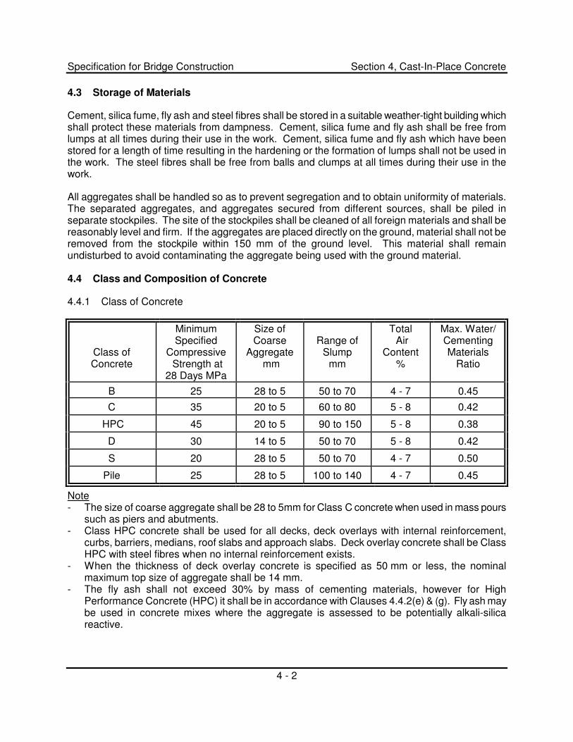
4.4.1 Class of Concrete
Class of Concrete
Minimum Specified
Compressive Strength at
28 Days MPa
Size of Coarse
Aggregate mm
Range of
Slump mm
Total Air
Content %
Max. Water/ Cementing Materials
Ratio
B 25 28 to 5 50 to 70 4 - 7 0.45
C 35 20 to 5 60 to 80 5 - 8 0.42
HPC 45 20 to 5 90 to 150 5 - 8 0.38
D 30 14 to 5 50 to 70 5 - 8 0.42
S 20 28 to 5 50 to 70 4 - 7 0.50
Pile 25 28 to 5 100 to 140 4 - 7 0.45
Note - The size of coarse aggregate shall be 28 to 5mm for Class C concrete when used in mass pours
such as piers and abutments. - Class HPC concrete shall be used for all decks, deck overlays with internal reinforcement,
curbs, barriers, medians, roof slabs and approach slabs. Deck overlay concrete shall be Class HPC with steel fibres when no internal reinforcement exists.
- When the thickness of deck overlay concrete is specified as 50 mm or less, the nominal maximum top size of aggregate shall be 14 mm.
- The fly ash shall not exceed 30% by mass of cementing materials, however for High Performance Concrete (HPC) it shall be in accordance with Clauses 4.4.2(e) & (g). Fly ash may be used in concrete mixes where the aggregate is assessed to be potentially alkali-silica reactive.

Specification for Bridge Construction Section 4, Cast-In-Place Concrete
4 - 3
4.4.2 Class HPC and Class HPC with Steel Fibres
(a) Mix shall include silica fume and fly ash as supplementary cementing materials in combination with compatible air entraining, water reducing and/or superplasticizing admixtures, as required.
(a) The gradation limits for the fine aggregate shall conform to CSA A23.1, except that the amount of material finer than 160 �m shall not exceed 5%.
(c) Coarse aggregate shall conform to CSA A23.1 and the maximum combination of flat and elongated particles (3:1 ratio), as determined by CSA A23.2-13A, shall not exceed 10% of the mass of coarse aggregate.
(d) Minimum cement content (excluding supplementary cementing materials) shall be 335 kg/m3
(e) Sum of silica fume and fly ash by mass of cementing materials shall be 17% to 20%.
(f) Silica fume by mass of cementing materials shall be 6% to 8%.
(g) Fly ash by mass of cementing materials shall be 11% to 15%.
(h) Slump retention of trial mix after 45 minutes shall be at least 50% of initial slump. The initial slump of the trial mix shall be measured after an elapsed time from batching of not more than 15 minutes.
(i) Rapid chloride ion penetration shall be determined in accordance with ASTM C1202 on laboratory moist cured samples at 28 days. Rapid chloride ion penetration shall be less than 1000 coulombs for concrete without steel fibres or concrete containing corrosion inhibiting admixtures. A unit weight test shall be taken for every 100 m3 of concrete placed.
(j) An air-void spacing factor shall be determined in accordance with ASTM C457, modified point-count method at 100 times magnification. The average of all tests shall not exceed 230 �m with no single test greater than 260 �m. A unit weight test shall be taken for every 100 m3 of concrete placed.
(k) When Class HPC with steel fibres is specified, it shall contain 60 kg of 50 mm long Xorex 1, or an acceptable equivalent steel fibre, per cubic metre. The Contractor shall provide test results of the aluminum content in the steel fibres, for the consultants review, a minimum of two weeks prior to placing concrete at site.
(l) The temperature of the centre of the in-situ concrete shall not fall below 10�C or exceed 60�C and the temperature difference between the centre and the surface shall not exceed 20�C.
(m) Trial batch(es) shall be performed at least 35 days prior to placement of concrete at site to verify that requirements pertaining to compressive strengths at 7 and 28 days, rapid chloride ion penetration and air void system parameters of hardened concrete have all been met. The shrinkage of the trial batch concrete shall be measured in accordance with ASTM C157 except that drying shall commence after 7 days of curing and shrinkage determined after 28 days of drying. All data shall be submitted to the Consultant for information purposes.
Specification for Bridge Construction Section 4, Cast-In-Place Concrete
4 - 4
4.4.3 Temperature
The temperature of all classes of concrete not containing silica fume shall be between 10�C and 25�C at discharge. Temperature requirements for Class HPC and Class HPC with steel fibres shall be between 10�C and 20�C at discharge.
4.4.4 Aggregate Tests and Concrete Mix Design
The Contractor shall submit the mix design he proposes for each proposed class of concrete for the Consultant's review two weeks before scheduled placing of concrete. Aggregate tests and concrete mix design shall not be required for concrete used for the construction of culvert collars or cut-off walls when culverts are 3 metre diameter or smaller.
For each mix design the following aggregate analysis shall be provided:
- "Fine and Coarse Aggregate Sieve" (CSA A23.2-2A) - Amount of material finer than 80 �m in aggregate (CSA A23.2-5A) - "Organic Impurities in Sands for Concrete" - �Results of deleterious substances and physical properties of aggregates included in Table 12,
CSA A23.1-04" (Test Methods A23.2-23A, A23.2-24A and A23.2-29A) - �Assessment of Potential for Deleterious Alkali-Aggregate Reactivity (AAR)� (CSA A23.2-27A) - "Petrographic Examination of Coarse Aggregate for Concrete" shall be required for Class HPC
and Class HPC with steel fibres - �Sources of proposed aggregate�
The analysis of the aggregates shall be current and fully represent the material to be used in production. All sampling and testing shall have been done no more than 90 days prior to concrete production, except for petrographic examination of coarse aggregate for concrete which shall be no more than 120 days. Additional analyses of more recent sampling shall be provided as required to confirm that the aggregates continue to meet requirements. A break in production of a particular class of concrete shall not constitute the need for additional testing when the Contractor provides conclusive evidence that the material initially tested, is still representative.
If the fine aggregate consists of a blend from more than one source, the "Fine Aggregate Sieve" analysis shall show the gradation of the blended fine aggregates. Similarly in the case of blended coarse aggregates, the "Coarse Aggregate Sieve" analysis shall indicate the gradation of the blended coarse aggregates.
Fine aggregate, tested in accordance with CSA Test Method A23.2-7A, "Organic Impurities in Sands for Concrete", shall produce a colour not darker than the Standard colour (Organic Plate Number 3). Aggregate producing a colour darker than the Standard colour will be rejected in the absence of a satisfactory record of performance of a similar class of concrete (minimum 30 tests over the last 12 months); provisions 4.2.3.3.3.2 (a) & (b) of CSA Standard CAN3-A23.1-04 shall not apply.
The potential for deleterious alkali-aggregate reactivity shall be assessed in accordance with CSA A23.2-27A. This assessment shall include the risk level associated with structure size and environment, the level of prevention related to service life requirements and the determination of the appropriate preventative measures. For bridge structures, the service life is considered to be 75
Specification for Bridge Construction Section 4, Cast-In-Place Concrete
4 - 5
years. Current (less than 18 months old) test data evaluating the potential alkali-silica reactivity of aggregates tested in accordance with CSA A23.2-14A or CSA A23.2-25A is required. In the absence of current test data and outside of areas of known highly reactive aggregate, the aggregate shall be presumed to be moderately reactive.
Petrographic analysis on the proposed coarse aggregates shall be performed in accordance with CSA A 23.2-15A by experienced personnel employed by CSA certified laboratory. The (weighted) petrographic number shall not exceed 130, and the ironstone content shall not exceed 0.8%. The Petrographic Analysis report shall be stamped by either, a Professional Engineer, Professional Geologist, or a Geological Engineer registered in the Province of Alberta.
The sampling and testing of aggregates, and the concrete mix design shall be completed by an independent CSA certified and qualified concrete testing laboratory which shall have a permit to practice in the Province of Alberta. Concrete mix designs including sampling and testing of aggregates may be completed by the concrete supplier, with the condition that documentation is stamped by a Professional Engineer registered in the Province of Alberta. For these situations, the mix design shall be reviewed and stamped for compliance with respective specifications, by an independent CSA certified and qualified concrete testing laboratory having a permit to practice in the Province of Alberta. For either case, the testing laboratory shall provide an engineering opinion that concrete aggregate and mix designs are suitable for the intended use and are expected to perform to specified standards.
For Class HPC and Class HPC with steel fibres, the Contractor shall produce evidence satisfactory to the Consultant that the proportions selected will produce concrete of the quality specified. This shall include the preparation of satisfactory trial mixes, before the concrete is used. The trial mix shall be a minimum of 3 m3 or 50% of the rated mixer capacity (whichever is greater) and simulate the anticipated placing procedures at site. In preparing the trial mixes the workability and slump retention characteristics shall be assessed at 30, 45 and 60 minute intervals. In addition the concrete from the trial mixes shall also satisfy the rapid chloride ion penetration requirement in accordance with Section 4.4.2(i).
Concrete mixes that will be placed by concrete pump shall be designed for pumping.
4.4.5 Initial Mixes, and Adjustments
For all classes of concrete other than HPC and HPC with steel fibres, in cases of initial mixing operations or changes in source of water or aggregates, the mix adopted shall be designed for an excess compressive strength of 10% above the specified 28 day nominal compressive strength. After the mix has been adequately proven as to strength and performance, adjustment may be undertaken, but only with the acceptance of the Consultant. If, during the progress of the work, the mix design is found to be unsatisfactory for any reason including poor workability, the Contractor shall make the necessary adjustments. Notwithstanding the Consultant�s review of the design mix, it remains the Contractor's responsibility that the concrete meets all the requirements of this Specification.

Specification for Bridge Construction Section 4, Cast-In-Place Concrete
4 - 6
4.5 Measurement of Materials
Coarse and fine aggregate materials shall be separated and measured separately by weighing, except as otherwise specified or where other methods are specifically authorized by the Consultant. The apparatus provided for weighing the aggregates and cement shall be suitably designed and constructed for this purpose. Each size of aggregate, and the cement, shall be weighed separately. The accuracy of all weighing devices shall be such that successive quantities can be measured to within one percent of the desired amount. The mixing water shall be measured by volume or by weight. The water measuring device shall be capable of control accurate to plus or minus 1/2 % of the design quantity. All measuring devices shall be subject to acceptance. Unless otherwise accepted, air entraining agent and other admixtures shall be added to the mix in a water-diluted solution; the dilution of the solution shall be accepted by the Consultant. For mix adjustments at the site, the Contractor shall maintain facilities to control the amount of superplasticizer and air entrainment so that the required tolerances can be met.
4.6 Mixing Concrete
Mobile continuous mixers or other such concrete supply equipment will not be accepted for use.
4.6.1 General
All concrete shall be mixed thoroughly with all ingredients uniformly distributed. The Consultant may require that the uniformity of the mixed concrete be tested for conformance with CSA A23.1, Clause 5.2.3.5. The �Batch� is considered as the quantity of concrete inside the mixer regardless of size of the mixer. The mixing period shall be measured from the time all materials are in the mixer drum.
The Contractor shall in no case load the mixer above its rated capacity. The Contractor shall maintain the mixer in good condition. Inner surfaces of the mixer shall be kept free of hardened concrete and mortar. Mixer blades which are bent or worn down so as to affect the mixing efficiency shall be renewed. Any mixer leaking mortar or causing waste of materials through faulty charging shall be taken out of service until repaired. The Contractor shall, at all times, operate the mixer at the speed recommended by the Manufacturer and shall, if requested, supply the Manufacturer's certification of the mixing capacity of the machine in use.
The mixer shall be fitted with an accurate and dependable means for measuring the water added, which is not affected by variation in pressure in the water supply line. All joints, valves and other parts shall be maintained so that there is no leakage of water into the mixer drum. Failure of the Contractor to have an accurately working and dependable water gauge on a mixer shall be cause for the Consultant to prohibit the mixer to be used.
Water shall be released first and continue to flow while the solid materials are entering the mixer. The water discharge pipe shall be so arranged and be of such size that the flow into the mixer is completed within the first quarter of the mixing time, and the water is delivered well within the mixer where it will be quickly mixed with the entire batch.
Air entraining agents and admixtures shall be placed in the mixer after the initial water is in the mixer drum but before the remaining materials are added. Superplasticizer shall be added after initial mixing and as per the manufacturer�s recommendation.

Specification for Bridge Construction Section 4, Cast-In-Place Concrete
4 - 7
4.6.2 Truck Mixing
Truck mixers, unless otherwise authorized by the Consultant, shall be of the revolving drum type, watertight, and so constructed that the concrete can be mixed to ensure uniform distribution of materials throughout the mass. All materials for the concrete shall be accurately measured in accordance with Section 4.5, and charged concurrently at the proportions which satisfy the accepted mix design into the drum at the production plant. Increases in water-cement ratio will not be permitted.
The maximum size of batch in truck mixers shall not exceed the maximum rated capacity of the mixer as stated by the manufacturer and stamped in metal on the mixer. Truck mixing shall commence immediately upon introduction of ingredients into the drum and be continued for at least 50 revolutions with the mixing rate being in accordance with the manufacturer�s recommended rate, and shall be such as to thoroughly mix the concrete.
When adjustment to the mix by adding water, air entraining agent or superplasticizer at the site is authorized by the Consultant, the mixer shall be run for a minimum of 20 additional revolutions to ensure homogeneity of the concrete before discharge. Discharge chutes shall be kept clean and free from hardened concrete and shall be wetted down prior to use.
4.6.3 Time of Hauling
The maximum time allowed for all classes of concrete other than Class HPC and Class HPC with steel fibres including delivery to the site of the work and discharge shall not exceed 90 minutes after batching. Batching of all classes of concrete is considered to occur when any of the mix ingredients are introduced into the truck mixer drum, regardless of whether or not the drum is revolved. For Class HPC and Class HPC with steel fibres this requirement is reduced to 70 minutes. In hot weather, or under conditions contributing to quick setting of the concrete, these times may be reduced as determined by the Consultant. Deviations from these requirements will be addressed in the Special Provisions.
4.7 Delivery
The Concrete supplier shall have sufficient plant capacity and satisfactory transporting equipment to ensure continuous delivery at the rate required. The rate of delivery of concrete during concreting operations shall be such that the development of cold joints will be precluded not occur. The methods of delivering and handling the concrete shall facilitate placing with a minimum of rehandling, and without damage to the structure or the concrete.
4.8 Pour Schedules
The Contractor shall outline to the Consultant the proposed pour schedule for any particular pour. If in the opinion of the Consultant the amount of pour is deemed larger than can be poured with the facilities outlined the Contractor shall either:
(a) Limit the amount to be poured at any time (using adequate construction joints), or
(b) Augment his facilities in order to complete the proposed pour, or
(c) In the case of continuous pouring provide additional crews and have adequate lighting to provide for proper placing, finishing and inspecting.
Specification for Bridge Construction Section 4, Cast-In-Place Concrete
4 - 8
4.9 Inspection and Testing
The Consultant shall be afforded full facilities for the random quality assurance inspection and testing that may be carried out relative to the concrete itself and/or the constituent materials. This includes at the worksite and any plant used for the manufacture of concrete wherever this may be situated. The facilities shall be adequate in the opinion of the Consultant to permit proper sampling of concrete, making of test cylinders and testing slump and air content. The proper storage of all site cast concrete cylinders in accordance with the relevant specifications is the responsibility of the Contractor and shall be provided prior to any concrete pour.
The results of the quality assurance testing carried out by the Consultant will serve to monitor and review the quality control program of the Contractor.
The Contractor shall utilize ACI or CSA certified testers with extensive related experience to test at site, the air content, slump, and temperature of each batch; results of all such tests shall be provided to the Consultant. Additional tests will be required if the results are borderline or widely variable. In case of an unacceptable result, one check test will be permitted. The certified testers shall also cast the test cylinders as specified in 4.9.3 �Test Cylinders�.
The certification of the testers shall be current and available for examination by the Consultant.
4.9.1 Strength Tests
A "Strength Test" shall consist of the compression tests of four standard test specimens, sampled, made, cured, and tested in accordance with CSA Standard Specifications as referenced with modifications as indicated. One cylinder shall be tested at seven days. The 28 day test result shall be the average of the strengths of the remaining three specimens, except that if any specimen in a test showing distinct evidence of improper sampling, molding or testing, shall be discarded and the remaining strengths averaged. Additional cylinders may be cast, at the discretion of the Consultant or Contractor.
For Class HPC and Class HPC with steel fibres, the Contractor shall take a strength test to represent each approximate 10 m3 portion of the concrete pour. For all other concrete, the Contractor shall take a strength test to represent each bridge element or portion of the element (ie. abutment seat, abutment backwall, pier footing and pier cap), except on larger pours a strength test will be taken to represent each approximately 30 m3 portion of the concrete pour. Such tests shall be taken from representative batches as determined by the Consultant.
4.9.2 Sampling
Sampling of concrete shall be carried out in accordance with CSA Standard A23.2-1C. When a concrete pump is used to place concrete, sampling shall be at the end of the discharge hose.
4.9.3 Test Cylinders
Making and curing concrete test cylinders shall be carried out in accordance with CSA Standard A23.2-3C, except that the time for cylinders to reach the testing laboratory shall be between 20 and 48 hours. The test cylinders shall be cast by the Contractor in standard CSA approved heavy duty steel or plastic moulds. Plastic moulds shall have a wall thickness of at least 6 mm. The Contractor
Specification for Bridge Construction Section 4, Cast-In-Place Concrete
4 - 9
shall provide properly designed temperature-controlled storage boxes for test cylinders, as specified in Section 5.3.2.1 of CSA Standard A23.2-3C, for a period of at least 24 hours, and further protection, as required, from adverse weather and mishandling until removed from the site. The Contractor shall provide a max-min thermometer for each storage box and record site curing temperatures for all test cylinders. Storage in a portable building which will be used by Contractor's personnel or the Consultant during the first 24 hour storage period will not be permitted. Storage facilities shall be provided, installed, and accepted before any concrete is placed.
The Contractor shall be responsible to deliver the test cylinders to an independent CSA certified testing laboratory. Handling and transporting of the cylinders shall be in accordance with CSA Standard 23.2-3C. No extra laboratory curing time will be allowed for cylinders that are delivered late to the laboratory. For Class HPC and HPC with steel fibres, the ends of cylinders shall be ground flat prior to testing. A copy of the test results shall be forwarded to the Consultant and Concrete Producer within 2 days of the break date.
If the test cylinders exhibit frost etchings or were stored at temperatures below 10oC or above 25oC, or are otherwise mishandled resulting in unreliable strength test results, the Department or Consultant may reject these portions of the Work, unless core-testing, at the Contractor's expense confirms the in-situ strength of the concrete.
The Contractor shall be responsible for all costs for concrete testing, including but not limited to making and curing test cylinders, transporting cylinders to an independent certified testing laboratory of his choice, storage, curing, strength testing, and providing written reports of the concrete test results to the Consultant.
The Contractor shall also be responsible for costs for supplying CSA approved heavy duty steel or plastic moulds, curing and delivering test cylinders cast by the Consultant, for quality assurance purposes to the same independent certified testing laboratory that he selects. Quality assurance testing will be carried out by the Consultant and the costs for testing and provision of concrete test cylinder reports will be paid for by the Department.
4.9.4 Slump
Slump tests shall be made at the discretion of the Consultant in accordance with CSA Standard A23.2-5C.
4.9.5 Air Content
Air content tests shall be made in accordance with CSA Standard A23.2- 4C.
4.9.6 Testing Cylinders
Test cylinders will be tested in compression in accordance with CSA Standard A23.2-9C by an independent CSA certified engineering laboratory engaged by the Contractor.
Specification for Bridge Construction Section 4, Cast-In-Place Concrete
4 - 10
4.9.7 Failure to Meet Slump or Air Content Specifications
In the event that slump and/or air content are outside the specified tolerance range, as determined by the Contractor's or the Consultant's testing, the Consultant may, accept adjustments of the deficient condition as an alternate to rejection provided adjustments are made within the maximum time allowed as specified in 4.6.3. Concrete that does not meet the specifications will be rejected after the maximum time is exceeded.
For Class HPC and Class HPC with steel fibres the Contractor will be allowed to adjust only the quantities of superplasticizer and air entraining agent. Addition of water at site to the batch will only be permitted subject to an alternate batching procedure accepted by the Consultant and the Department. In no case shall accepted batch adjustment relieve the Contractor of his responsibility for the eventual durability, strength, and acceptability of the concrete concerned. The Department or Consultant reserves the right to reject any batch in the event of confirmed unacceptability, and to require immediate removal of any concrete from this batch which may have already been placed in the structure.
4.10 Falsework and Formwork
4.10.1 General
Detailed falsework and formwork drawings shall be supplied to the Consultant for review and examination as to concept only. The drawings shall be submitted three weeks before construction of the work begins. The drawings shall bear the Seal of a Professional Engineer registered in Alberta, who shall assume full responsibility to ensure that his design is being followed in construction of the falsework and formwork. Alberta Safety and compliance with the Occupational Health and Safety Act and Regulations thereunder, shall be integral parts of his design. All falsework and formwork shall be fabricated in accordance with the drawings.
4.10.2 Design
For the design of falsework and formwork, the density of fresh concrete shall be assumed to be 2400 kg/m3. All forms shall be of wood, metal or other acceptable materials, and shall be designed and built mortar-tight and of sufficient rigidity to prevent distortion due to the pressure of vibrated concrete and other loads incidental to the construction operation. The forms shall be substantial and unyielding, and shall be designed so that finished concrete will conform to the design dimensions and contours. The shape, strength, rigidity, water tightness and surface smoothness of re-used forms shall be maintained at all times. Any warped or bulged formwork must be repaired or replaced before being used. Forms which are unsatisfactory in any respect shall not be used.
All falsework shall be designed and constructed to provide the necessary rigidity and to support the loads without appreciable settlement or deformation. Falsework which cannot be founded on a satisfactory footing shall be supported on piling which shall be spaced, driven and removed in a manner acceptable to the Consultant.
For timber formwork, drawings shall specify the type and grade of lumber and show the size and spacing of all members. The formwork drawings shall also show the type, size and spacing of all ties or other hardware, and the type, size and spacing of all bracing.
Specification for Bridge Construction Section 4, Cast-In-Place Concrete
4 - 11
When forms appear to be unsatisfactory in the opinion of the Consultant, either before or during the placing of concrete, the Consultant will order the work stopped until the defects have been corrected.
For narrow walls and columns, where the bottom of the form is inaccessible, removable panels shall be provided in the bottom form panel to enable cleaning out of extraneous material immediately before placing the concrete.
4.10.3 Forms for Exposed Surfaces
Forms for exposed surfaces which require a Class 1 "Ordinary Surface Finish" shall be made of good quality plywood, or an acceptable equivalent, of uniform thickness, with or without a form liner. Forms for exposed surfaces requiring a Class 2 "Rubbed Finish" or Class 3 "Bonded Concrete Surface Finish" shall be all new material, made of "Coated Formply", consisting of Douglas Fir substrate with resin-impregnated paper overlay and factory treated chemically active release agent, "ULTRAFORM", or "POURFORM 107", are acceptable formwork panels, however other forming panels will be considered if approved equal. All form material for exposed surfaces shall be full-sized sheets, as practical. The re-use of any forms must have the acceptance of the Consultant.
All forms for exposed surfaces shall be mortar-tight, filleted at all sharp corners, and given a bevel or draft in the case of all projections. At the top edges of exposed surfaces, the chamfers are to be formed by chamfer strips.
The minimum acceptable forming for all exposed concrete where the pour height is 1.5 m or less shall have 18 mm approved plywood, supported at 300 mm maximum on centres. Where the pour height is greater than 1.5 m the minimum acceptable forming for all exposed concrete shall have 18 mm approved plywood, "Coated Formply", supported at 200 mm maximum on centres. The support spacing specified here assumed the use of new material. Closer spacing may be required in case of re-used material. Strong-backs or walers placed perpendicularly to the supports shall be employed to ensure straightness of the form.
Metal bolts or anchorages within the forms shall be so constructed as to permit their removal to a depth of at least 20 mm from the concrete surface. Break-back type form ties shall have all spacing washers removed and the tie shall be broken back a distance of at least 20 mm from the concrete surface. All fittings for metal ties shall be of such design that, upon their removal, the cavities which are left will be of the smallest possible size. Torch cutting of steel hangers and ties will not be permitted. Formwork hangers or ties for exposed surfaces of decks, curbs and barriers shall be an acceptable break-back type with surface cone, or removable threaded type. As practical, internal ties for the construction of curb and barriers should not be used. Cavities shall be filled with cement mortar and the surface left sound, smooth, even and uniform in color.
4.10.4 Forms for Unexposed Surfaces
The minimum acceptable forming for unexposed concrete shall have 15 mm plywood supported at 400 mm maximum on centres.
4.10.5 Standard Details
Refer to Standard Drawing S-1411 "Standard Concrete Joints" and Standard Drawing S-1412 "Standard Construction Joints," included with these Specifications, for details of joints.
Specification for Bridge Construction Section 4, Cast-In-Place Concrete
4 - 12
4.10.6 Deck Formwork
Unless otherwise noted, diaphragms and girders will be designed for construction loads during deck concrete pour in accordance with CSA-S6-00 Clause 3.16, and the loads assumed for such design shall be shown on contract drawings. Where construction loads or loading conditions vary from those shown, the Contractor shall be responsible for maintaining girder stability until the deck concrete has gained sufficient strength. Where required, deck formwork design shall include any additional bracing system to those shown on the contract drawings. Care shall be taken in the design and installation of support brackets to avoid damage to girder flanges and webs. Where such brackets bear against girder webs, the girder webs shall be protected by timber or neoprene softeners. Effects of concentrated loads on thin webs shall be checked, and where necessary, sufficient means shall be provided to distribute or carry such concentrated loads to the supporting flanges or stiffeners.
Formwork for decks, curbs, sidewalks, and parapets shall be fabricated so that the lines and grades shown on the drawings are achieved. Girders will be erected to normally accepted industry standards of tolerance; it shall be necessary to adjust the formwork to compensate for variances in girder dimensions, positioning, alignment, and sweep.
Prior to commencing deck formwork, the Contractor shall profile all the girders and determine the deck concrete thickness values required to achieve the specified gradeline. This information shall be provided to the Consultant prior to commencing any deck formwork.
In the event that actual girder camber values vary significantly from the estimated values indicated on the drawings, the Consultant will require the Contractor to raise or lower the gradeline accordingly.
4.11 Protection of "Weathering" Steel Girders
Where steel girders are fabricated of "weathering" steel, it is essential that the uniformity of rust formation is not adversely affected by the Contractor's operation.
The Contractor shall exercise utmost care and provide the necessary protection to prevent marking or staining of the girders. All joints between deck formwork and steel members (including interior girders, and diaphragms) shall be sealed to prevent leakage of cement paste or concrete. Caulking, duct tape, ethafoam, or any other suitable means or material, shall be used to achieve the seal.
Should foreign material spill onto the girders despite the protection provided, the Contractor shall clean off, wash, and sandblast the contaminated areas, to the satisfaction of the Consultant. Additionally, should the exterior face of an exterior girder become stained or marked, the entire exterior face of the girder line shall be lightly sandblasted and "weathered" so that uniformity of girder color, in the opinion of the Consultant, is achieved.
"Weathering" shall be achieved by repeatedly fogging the exterior girder faces with clean water and allowing them to dry. Fogging should leave the girders wet but not "running wet", and should be repeated when the girders are completely dry.
The cost of sealing and stain-prevention shall be included in the unit price bid for the deck concrete; no separate or additional payment will be made for the cost of protecting the girders, nor for any cleaning, sandblasting or "weathering" made necessary by the Contractor's operation.
Specification for Bridge Construction Section 4, Cast-In-Place Concrete
4 - 13
4.12 Protection of Substructure Units from Rust Staining
The substructure will be subject to staining, during the period from erection to casting of the concrete deck. The Contractor shall be responsible either to take suitable measures to coat or cover the piers and abutments before erection, or to adequately remove all staining so that the required concrete finishes may be applied with no trace of stain remaining. Final acceptance of pier finish will not be given until after all deck and curb concrete is in place.
This work will be considered incidental to the application of the specified concrete surface finish, and no separate payment will be made.
4.13 Removal of Falsework, Forms and Housing
Forms and their supports shall not be removed without the acceptance of the Consultant. In determining the time for the removal of falsework, forms and housing, and the discontinuance of heating, consideration shall be given to the location and character of the structure, the weather and other conditions influencing the curing of the concrete, and the materials used in the mix.
The following guide for removal of forms and supports may be used if the temperature of the concrete is maintained at no less than 15oC:
Portion of Work Age or Minimum Strength
Arches and girders - 14 days (or 80% of 28-day strength) Pier caps and beams - 5 days (or 50% of 28-day strength) Columns - 1 to 3 days Decks & Slabs - 5 days (or 50% of 28-day strength) Vertical faces of supported elements - 12 to 24 hours Walls over 3 m high - 2 days
Supports and forms may be removed from arches, girders, deck, pier caps and beams earlier than the minimum curing periods specified above, with the Consultant's acceptance. In seeking acceptance the Contractor shall, at his own expense, furnish evidence satisfactory to the Department and Consultant that the strength of the concrete in place has attained the above noted percentage of the specified 28-day strength before removal.
Supports shall be removed in such a manner as to permit the concrete to uniformly and gradually take the stresses due to its own weight.
All formwork must be removed from the completed structure. For certain special situations, formwork may remain in place, when the Contractor�s formal request is approved by the Consultant and Department.
4.14 Handling and Placing Concrete
4.14.1 General
The Contractor shall give the Consultant a minimum of two days advance notice of a concrete pour date or a change to a pour date.
Specification for Bridge Construction Section 4, Cast-In-Place Concrete
4 - 14
The method of concrete placement shall have a consistent, minimal impact on the concrete properties. All equipment proposed for use in mixing, conveying, placing and compacting the concrete shall be reviewed and accepted by the Consultant prior to its use. All the necessary equipment for any particular pour shall be on site and proven to be in working condition before the pour commences, with backup equipment on site as determined by the Consultant. The equipment shall be well maintained, suitable in kind and adequate in capacity for the work.
In preparation for the placing of concrete, all sawdust, chips and other construction debris and extraneous matter shall be removed from the interior of forms. Struts, stays, and braces, serving temporarily to hold the forms in correct shape and alignment, pending the placing of concrete at their locations, shall be removed when the concrete placing has reached an elevation rendering their service unnecessary. These temporary members shall be entirely removed from the forms and not buried in the concrete.
Concrete shall be placed so as to avoid segregation of the materials and the displacement of the reinforcement. When placing operations would involve free drop of concrete by more than 1 m, it shall be deposited through metal or other acceptable pipes.
Concrete for the structure shall be deposited in the forms in the order indicated on the drawings, and each portion placed between construction joints shall be placed in one continuous operation. No other order of pouring shall be done unless otherwise accepted by the Consultant.
Concrete placing operations shall not work off, or transport concrete directly over, concrete already placed, when this concrete is less than 48 hours old, no matter what system of runways, supports or protection is used on the surface of the concrete already placed, if it is subjected thereby to live or dead loads. Concrete more than 48 hours old but of less than the specified 28-day strength shall not be loaded without the acceptance of the Consultant.
4.14.2 Consolidation
Concrete, during and immediately after depositing, shall be thoroughly consolidated. The consolidation shall be done by mechanical vibration subject to the following provisions:
- The vibration shall be internal unless special authorization of other methods is given by the Consultant, or the Consultant requests the use of other methods.
- Vibrators shall be of a type and design acceptable to the Consultant. They shall be capable of transmitting vibrations to the concrete at frequencies of not less than 4500 impulses per minute
- The intensity of vibration shall be such as to visibly affect a mass of concrete of 25 mm slump over a radius of at least 0.5 m.
- The Contractor shall provide a sufficient number of vibrators to properly compact each batch immediately after it is placed in the forms.
- Vibrator operators shall be suitably instructed in the use of vibrators, and the importance of adequate and thorough vibration of the concrete.
- Vibrators shall be manipulated so as to thoroughly work the concrete around the reinforcement
Specification for Bridge Construction Section 4, Cast-In-Place Concrete
4 - 15
and imbedded fixtures and into the corners and angles of the forms. Vibration shall be applied at the point of deposit and in the area of freshly deposited concrete. The vibrators shall be inserted vertically and withdrawn out of the concrete slowly. The vibration shall be of sufficient duration and intensity to thoroughly compact the concrete, but shall not be continued so as to cause segregation. Vibration shall not be continued at any point to the extent that localized areas of grout are formed. Application of vibrators shall be at points uniformly spaced and not farther apart than the radius over which the vibration is visibly effective.
- Vibration shall not be applied directly or through the reinforcement of sections or layers of concrete which have hardened to the degree that the concrete ceases to be plastic under vibration. It shall not be used to make concrete flow in the forms over distances so great as to cause segregation, and vibrators shall not be used to transport concrete in the forms.
- Vibration shall be supplemented by such spading as is necessary to ensure smooth surfaces and dense concrete along form surfaces and in corners and locations impossible to reach with the vibrators.
4.14.3 Additional Requirements
When concrete placing is discontinued, for whatever reason, all accumulations of mortar splashed on the reinforcing steel and the form surfaces shall be removed. Dried mortar chips and dust shall not be puddled into the unset concrete. If the accumulations are not removed prior to the concrete becoming set, care shall be exercised not to injure or break the concrete-steel bond at and near the surface of the concrete, while cleaning the reinforcing steel.
Concrete shall be placed while fresh and before it has taken its initial set. Retempering of partially hardened concrete with additional water will not be permitted. No concrete shall be used which does not reach its final position in the forms within the time stipulated under 4.6.3 "Time of Hauling" above.
After initial set of the concrete the forms shall not be jarred and no strain shall be placed on the ends of reinforcing bars which project.
Concrete which would be adversely affected by the presence of freestanding water shall be protected to prevent its occurrence, and the Contractor shall take whatever steps may be necessary to prevent free water build-up in the event of unexpected rainfall or similar occurrences for the first 24 hours.
Water used to keep equipment clean during the pour, or to clean equipment at the end of the pour, shall be discharged clear of the structure.
4.14.4 Pumping
The operation of the pump shall produce a continuous flow of concrete without air pockets. The equipment shall be so arranged that the impact on the plastic air content of the concrete shall not vary by �0.5% and that no vibrations result which might damage freshly placed concrete. When pumping is completed, the concrete remaining in the pipeline, if it is to be used, shall be ejected in such a manner that there will be no contamination of the concrete or separation of the ingredients.
Specification for Bridge Construction Section 4, Cast-In-Place Concrete
4 - 16
4.15 Placing Pile Concrete
4.15.1 General
The Contractor shall make every attempt to obtain a �Dry� pile hole prior to placing pile concrete. In the event that all reasonable attempts at obtaining a dry hole fail, the Consultant may permit the placement of pile concrete under water.
4.15.2 Concrete Placed in the Dry
Pile concrete shall be placed by means of a hopper equipped with a centre pipe drop tube. The pipe drop tube shall be a minimum of 200 mm in diameter and 2 m long. Concrete may be placed free fall, providing the fall is vertically down the centre of the casing or drilled hole and there are no transverse ties or spacers. Pile concrete shall have a slump range of 100 - 140 mm at time of discharge. Concrete in the upper 3 m of the piles shall be consolidated by the use of an acceptable concrete vibrator.
4.15.3 Concrete Placed under Water
Placement of pile concrete under water shall be in accordance with Section 4.21 of this Specification.
4.16 Placing Deck, Curb, Barrier, Median and Deck Overlay Concrete
4.16.1 General
All deck, curb, barrier, median and deck overlay concrete shall be Class HPC, or Class HPC with Steel Fibres, as specified. Concrete placing will not be permitted when the air temperature is below +5�C or above 22�C, nor in the event of rain or excessive wind or dust, nor when there are other conditions judged by the Consultant to be detrimental to the concrete. Deck concrete placing shall normally be between the hours of 6:00 pm and 10:00 am except with specific acceptance of the Department and Consultant. Night pours shall require proper lighting as reviewed and accepted by the Consultant. The temperature of the concrete during discharge shall be between 10�C and 20�C unless reviewed and accepted otherwise by the Consultant. The temperature of the mix shall be maintained below the 20�C maximum temperature by the inclusion of ice to the mix which shall not alter the design water-cement ratio. Immediately prior to placing concrete, the substrates shall be thoroughly wetted down with clean water.
All deck concrete and deck overlay concrete shall be consolidated in accordance with Section 4.14.2 even when vibratory drum type finishing machines are used.
Placing/Finishing Machines For all deck concrete and deck overlay concrete, screeding shall be by concrete placing/finishing machines as follows or acceptable equivalents:
- Bidwell Model RF200 or Model 364 - Gomaco Model C450
The Contractor shall provide two work bridges, separate from the placing/finishing machine, of
Specification for Bridge Construction Section 4, Cast-In-Place Concrete
4 - 17
adequate length to completely span the width of the pour. The work bridges will facilitate the operations of concrete finishing and placing of wet burlap, and shall also be made available to the Consultant for straight-edge checking. The work bridges shall be supported essentially parallel to the concrete surface, between 250 mm and 600 mm above the concrete surface, and shall be at least 800 mm wide to permit diverse uses concurrently, and be rigid enough that dynamic deflections are insignificant.
4.16.2 Screed Guide Rails
Acceptable steel screed guide rails shall be installed to suit the profile of the required surface and to ensure a smooth and continuous surface from end to end of the bridge. Guide rails must be located outside of the finished surface of the pour for overlay concrete and also for deck concrete, unless specified otherwise in the Special Provisions. All rails and supports shall be removed with minimum disturbance to the concrete.
4.16.3 Dry-Run
The finishing machine shall be set-up to match the skew angle of the bridge, when the skew angle exceeds 15�. For skewed bridge structures on vertical curves this requirement may be altered to suit actual site conditions.
The finishing machine and guide rails shall be adjusted so that the height of the screed will finish the concrete to the design gradeline and crown. To confirm the adjustment of the machine and guiderails, the screed shall be dry-run prior to the pour and clearance measurements taken at each of the girder tenth points, and provided to the Consultant for review and acceptance. Re-setting of the machine and/or screed rails shall be done as necessary, to obtain an acceptable dry-run. Adjustments to the machine or screed rails will not be permitted after an acceptable dry-run has been completed.
Where screed rails are supported on cantilevered formwork that could deflect under the weight of the fresh concrete and the deck finishing machine, the Contractor shall pre-load a section of the cantilevered formwork on each side of the bridge to determine deflections that will occur during concrete placement. The formwork, machine and/or screed rails shall be adjusted to compensate for the expected formwork deflection.
4.16.4 Fog Misting and Wet Cure Systems
Details of the fog misting and wet cure systems shall be provided to the Consultant for review and acceptance three weeks prior to the scheduled pour date. Details shall include information with regards to the type and description of equipment and materials being used and work method/techniques employed to satisfactorily carry out the work.
4.16.5 Screeding Concrete
The screed shall be moved slowly and at a uniform rate. In general, the direction of pouring should be from the low end of the bridge to the high end. A roll of concrete shall be maintained along the entire front of the screed at all times to ensure the filling and consolidation of the surface concrete. The contractor shall also ensure that the required concrete thickness is being placed by randomly probing the concrete behind the finishing machine.

Specification for Bridge Construction Section 4, Cast-In-Place Concrete
4 - 18
Screeding shall be completed in no more than two passes. The screed shall not be allowed to run except when screeding is actually in progress. The screeded surface shall not be walked on or otherwise damaged.
4.16.6 Bull Floating/Surface Texturing
The concrete surface produced behind the finishing machine shall be magnesium floated the minimum amount necessary to ensure that the surface is free from open texturing, plucked aggregate and local projections or depressions. It is imperative that competent workers be employed to carryout bull floating and surface texturing.
4.16.7 Surface Defects and Tolerances
The finished surface of the concrete shall conform to the design gradeline profiles as indicated on the drawings and/or as determined on site.
The surface shall be free from open texturing, plucked aggregate and local projections.
Except across the crown, the surface shall be such that when tested with a 3 m long straight edge placed anywhere in any direction on the surface, there shall not be a gap greater than 3 mm between the bottom of the straight edge and the surface of the deck anywhere below the straight edge.
The surface shall be checked by the Contractor, as described above, immediately after final bull floating and before texturing.
The surface shall again be checked by the Contractor at the end of the curing period in the same manner and to the same tolerance.
Areas that do not meet the required surface accuracy shall be clearly marked out and the Contractor shall, at his own expense:
(a) Grind down any areas higher than 3 mm but not higher than 10 mm above the correct surface.
(b) Correct any areas lower than 3 mm but not lower than 10 mm below the correct surface, by grinding down the adjacent high areas.
(c) When the deviation exceeds 10 mm from the correct surface, the deck slab shall be removed and replaced in accordance with Section 20.3.2 �Partial Depth Repair�, resulting in a product that is in no way inferior to the adjacent undisturbed slab. Replaced areas shall be at the Contractor's expense.
Grinding shall be carried out by an approved machine, of a type and capacity suitable for the total area of grinding involved, until the surface meets the specified requirements.
All corrective work will require the Contractor to submit a proposal for review and acceptance by the Department and Consultant, prior to commencement of any work.
If the surface is damaged in any way by construction operations, or if the deck shows signs of distress or scaling prior to the final acceptance of the deck, it shall be repaired or replaced by the Contractor at his own expense.
Specification for Bridge Construction Section 4, Cast-In-Place Concrete
4 - 19
4.17 Placing Approach Slab and Roof Slab Concrete
After properly placing and consolidating the concrete, it shall be struck off and screeded to conform to the required cross-section and grade. Concrete placing shall be carried out in a manner such that the newly deposited concrete is continually placed against fresh concrete across the entire face of the pour and the formation of cold joints is avoided. A slight excess of concrete shall be kept in front of the screed at all times.
The surface shall then be floated longitudinally, transversely or in both directions as necessary to ensure that the surface is free from open texturing, plucked aggregates, and local projections or depressions. The surface shall be such that it does not vary more than 5 mm from the required lines, under a 3 m straightedge.
4.18 Concreting Shear Keys and Diaphragms
Precast concrete girders will be erected to normally accepted industry standards for tolerance. Forming of shear keys and diaphragms shall be designed to accommodate variations in girder dimensions, positioning, alignment, camber and sweep. Before concreting, the girder keyways must be saturated with water for a period not less than 30 minutes, and must be coated with an approved bonding agent immediately ahead of the concrete. Concrete placed in the keyways shall be adequately vibrated, and trowelled smooth and flush to the girders. Immediately after trowelling, wet burlap or white filter fabric shall be placed on the shear keys and kept continuously wet for the next 72 hours.
4.19 Construction Joints
4.19.1 General
Construction joints shall be made only where indicated on the drawings or shown in the pouring schedule unless otherwise reviewed and accepted by the Consultant.
If not detailed on the drawings, or in the case of emergency, construction joints shall be placed as determined by the Consultant and according to the standard drawing. Shear keys or inclined reinforcement shall be used where necessary to transmit shear, or to bond the two sections together. Construction joints should be located to allow a minimum of 50 mm minimum concrete cover on reinforcing steel running parallel to the joint. Refer to Standard Drawing S-1412 "Standard Construction Joints" included with these Specifications.
4.19.2 Bonding
Before depositing new concrete on or against concrete which has hardened, the forms shall be retightened and the surface of the hardened concrete shall be thoroughly cleaned and saturated with water, with all free standing water removed. The placing of concrete shall be carried out continuously from joint to joint. The face edges of all joints which are exposed to view shall be carefully finished true to line and elevation.
4.20 Concreting in Cold Weather
The Contractor shall accept full responsibility for the protection of concrete during adverse weather conditions.

Specification for Bridge Construction Section 4, Cast-In-Place Concrete
4 - 20
When the ambient air temperature is, or is expected to be below 5oC, or when determined by the Consultant, the following provisions for cold weather concreting shall be put in place:
(1) All aggregate and mixing water shall be heated to a temperature of at least 20oC but not more than 65oC. The aggregates may be heated by either dry heat or steam; in the latter case the quantity of mixing water may need to be reduced. The temperature of the concrete shall be between 10oC and 25oC at the time of placing in the forms. In the case of mass pours, the Consultant may alter the temperature requirements to suit.
(2) The Contractor shall enclose the structure in such a way that the concrete and air within the enclosure can be kept above 15oC for a period of 7 days after placing the concrete. The enclosure shall be constructed so that a minimum 300 mm clearance exists between the enclosure and the concrete. To prevent overheating, the air temperature within the enclosure shall be monitored frequently, especially during the first 24 hours.
The relative humidity within the enclosure shall be maintained at not less than 65%. Heaters must be kept well clear of the formwork housing. Adequate ventilation is required to provide air for combustion, and to prevent the accumulation of carbon dioxide which can be harmful to the concrete. The use of salamanders, coke stoves, oil or gas burners and similar spot heaters which have an open flame and intense local heat is prohibited without the Consultant's specific acceptance.
The system of heating, and positioning of steam outlets, heaters, and fans, is to be designed to give the most uniform distribution of heat possible, and is subject to the review and acceptance of the Consultant.
(3) Before placing concrete, adequate pre-heat shall be provided to raise the temperature of formwork, reinforcing steel, previously-placed concrete, and/or soil to at least 10oC. The Contractor shall be responsible to make all arrangements for heating, and to ensure continuous protection from unsatisfactory temperature and moisture conditions during the curing period. The Consultant's acceptance of the Contractor's arrangements shall be obtained; it will be a requirement that pre-heat is adequate, in the Consultant's opinion, to ensure that no portion of the fresh concrete is damaged by freezing, or curing retarded by cold temperatures.
(4) Fully insulated formwork may be proposed as an alternative to provision of further heat during the curing period. Such formwork shall be designed and insulated with approved materials so that the initial heat of the mix, and the heat generated during the hydration of the cement, is retained to provide the specified curing conditions. The adequacy of the protection is the Contractor's responsibility.
(5) Protection and heating, where used, shall be withdrawn in such a manner so as not to induce thermal shock stresses in the concrete. The temperature of the concrete shall be gradually reduced at a rate not exceeding 10�C per day to that of the surrounding air. To achieve this, in a heated housing, the heat shall be slowly reduced and then shut off, and the whole housing allowed to cool to air temperature before the housing itself is removed. However, the protection shall not be removed until the temperature of the concrete has fallen to within 10�C of the temperature of the outside air.
Specification for Bridge Construction Section 4, Cast-In-Place Concrete
4 - 21
4.21 Depositing Concrete Under Water
Concrete shall not be deposited in water except as specified and with the acceptance of the Consultant and under his immediate supervision. Anti-washout admixtures incorporating viscosity modifiers (whelan gum, etc.) may be used when specifically reviewed and accepted by the Consultant.
Concrete to be deposited in water shall be of the specified class, with mix design modified to yield 150 mm to 175 mm slump, and with an excess of 15% of the cement quantity added beyond this designed amount. The mix should contain an approved �anti-washout� admixture to enhance the performance of the mix. The concrete temperature shall be between 10oC and 25oC.
To prevent segregation, concrete shall be carefully placed in a compact mass, in its final position, by means of a concrete pump. When specifically reviewed and accepted by the Consultant, a properly designed and operated tremie may be used. The concrete shall not be disturbed after being deposited. Still water shall be maintained at the point of deposit and the forms underwater shall be watertight.
When placing concrete under water, the discharge end of the concrete pump line shall be lowered to the bottom of the form or hole. Pumping shall then proceed with the end of the discharge line being continually buried no less than 500 mm below the surface of fresh concrete at all times, to maintain a seal until the form or hole is completely filled with fresh uncontaminated concrete.
A tremie, when reviewed and accepted, shall consist of a rigid tube having a diameter between 200 mm and 300 mm, and if constructed in sections it shall have flanged couplings fitted with gaskets. The discharge end shall be closed at the start of the work to prevent water entering the tube. The tremie tube shall be kept full to the bottom of the hopper, and water shall be kept out at all times. When a batch is dumped into the hopper, the flow of concrete shall be induced by slightly raising the discharge end, always keeping it in the deposited concrete. The flow shall be continuous until the work is completed. Sufficient tremies shall be used to place the concrete under water such that it is not necessary to move any of the tremies from one portion of the pour to another. The use of non-rigid tremie tubes will not be permitted.
Concrete shall not be placed in water which is below 4�C.
The surface of the concrete shall be kept as nearly horizontal as is practicable at all times. The discharge end of the tremie shall be kept buried at least 300 mm in previously placed concrete.
Dewatering will not be permitted while concrete is being placed. Dewatering may proceed when the concrete seal is sufficiently hard and strong. All laitance or other unsatisfactory material shall be removed from the exposed surface by scraping, chipping or other means which will not injure the surface of the concrete.

Specification for Bridge Construction Section 4, Cast-In-Place Concrete
4 - 22
4.22 Curing Concrete
4.22.1 General
Freshly deposited concrete shall be protected from freezing, abnormally high temperatures or temperature differentials, premature drying, excessive moisture, and moisture loss for the period of time necessary to develop the desired properties of the concrete.
All exposed concrete surfaces, other than Class HPC which are to receive a Class 2 or 3 finish, shall be moist cured. The Contractor shall cover the concrete surface(s) with a single layer of clean, soaking wet burlap or light colored filter fabric as soon as the surface will not be marred by so doing. The burlap or light colored filter fabric shall be kept continuously wet for 72 hours.
All unexposed concrete surfaces not requiring the application of silane sealer shall receive two applications of an approved curing compound. The rate of each application shall not be less than the rate specified by the manufacturer of the compound. Curing compound shall not be used on any construction joints or when cold weather concreting is in effect.
Where the formwork is left in place for 72 hours or more, no additional curing will be required for either exposed or unexposed concrete surfaces.
4.22.2 Curing Requirements for Concrete Slope Protection
Concrete slope protection shall receive 2 coats of a curing compound acceptable to the Consultant. The first coat is to be applied immediately after the concrete has been satisfactorily finished, and the second coat is to be applied within 3 hours after the application of the first coat. In cases where premature drying is severe or is anticipated to be severe, then moist curing, as specified in 4.22.1, will also be required.
4.22.3 Curing Requirements for Class HPC and Class HPC with Steel Fibres
For Class HPC and Class HPC with steel fibres, fog mist shall be applied continuously from the time of screeding until the concrete is covered with filter fabric or burlap, in such a way as to maintain high relative humidity above the concrete and prevent drying of the concrete surface. Water shall not be allowed to drip, flow or puddle on the concrete surface during fog misting, when placing the filter fabric or burlap or at any time before the concrete has achieved final set. Equipment and materials necessary for the fog mist system shall be demonstrated and approved prior to scheduling and placing of Class HPC.
Two layers of light colored filter fabric (Nilex C-14 or equivalent) or burlap shall be placed on the fresh concrete surface as soon as the surface will not be marred as a result of this placement. A fine spray of water shall be immediately applied to the filter fabric or burlap. Edges of the filter fabric or burlap shall overlap a minimum of 150 mm and shall be held in place without marring the surface of the concrete.
The filter fabric or burlap shall be in a continuously wet condition throughout the curing period, by means of a soaker hose or other means as reviewed and accepted by the Consultant. Curing with filter fabric or burlap and water shall be maintained for a minimum period of 7 days for deck overlay and concrete rehabilitation and 14 days for new bridge construction, with the exception of concrete

Specification for Bridge Construction Section 4, Cast-In-Place Concrete
4 - 23
for blockouts adjacent to deck joints, where the wet cure period is reduced to 3 days followed by the application of a chlorinated rubber curing compound.
During the seven day cure period for Class HPC and Class HPC with steel fibres, following the placement of concrete, the Contractor shall provide protection to ensure that the concrete temperature and the temperature differences remain within the limits specified in 4.4.2(l). The Contractor shall supply and install two thermocouplers, in the centre and at the surface of the concrete, for every 100 m2 of deck, at locations determined by the Consultant. The Contractor shall monitor and record the temperatures every four hours for the first 3 days after concrete placement and every 12 hours thereafter during remaining curing period. Daily temperature records shall be forwarded to the Consultant and Department.
4.22.4 Class HPC and Class HPC with Steel Fibres
After the curing period and before opening to public traffic, the Contractor and the Consultant shall jointly inspect the dry concrete surface(s) to identify all cracks. The Consultant will plot the width in millimetre and length in linear metres of cracks per square metre and report the findings to the Department. The Contractor shall repair the cracks at his own expense if crack width is 0.2 mm or more. The following procedure shall be used in the treatment of the same:
(a) Blow out cracks clean and dry with a jet of oil-free compressed air.
(b) Seal cracks with a gravity feed epoxy in accordance with the manufacturer�s instructions. The gravity feed epoxy shall maximize the penetration by taking into consideration the ambient temperature, the substrate temperature, the viscosity and pot life of the material being used. Gravity feed epoxy material shall be reviewed and accepted by the Consultant and the Department prior to its usage.
(c) When cracks extend the full depth of the deck slab, barriers or curbs or to the top layer of reinforcement of decks that are cast to grade, epoxy injection will be required. The epoxy material and injection procedure shall be submitted by the Contractor for acceptance of the Department and Consultant.
4.23 Concrete Finishing Under Bearings
All concrete areas on which bearing plates or pads are to be placed are to be at the required elevation, and are to be finished or ground to a smooth and even surface in preparation for bearing plates or pads. The finished surface shall not vary more than 1 mm over an area whose dimensions exceed the dimensions of the bearing plates by 60 mm. Air voids created by forming grout-pad depressions shall be filled with an approved patching material, well in advance of girder erection. In cold weather conditions this work shall be completed while the concrete is still warm.
4.24 Concrete Surface Finish
4.24.1 General
Surfaces requiring concrete finishing shall conform to the requirements of section 4.16.6, �Surface Defects and Tolerances�. All mortar patches shall be cured as specified in section 4.22, �Curing Concrete�.
Specification for Bridge Construction Section 4, Cast-In-Place Concrete
4 - 24
On unexposed concrete surfaces all cavities, honeycomb, and other deficiencies shall be thoroughly chipped out, cleaned, and after having been kept saturated with water for a period of not less than 30 minutes, shall be filled with cement mortar.
On exposed concrete surfaces to 600 mm below grade or, in the case of river piers, 600 mm below lowest water level, surface finishes shall be applied as follows:
Class 1 Ordinary Finish - all exposed concrete surfaces unless other finishes are specified.
Class 2 Rubbed Finish - solid shaft river piers - inside surfaces of curb, parapet and sidewalk - median vertical faces.
Class 3 Bonded Concrete Finish - abutment seats except top surface - pier caps except top surface - exterior faces of curtain walls/wingwalls - grade separation piers except top surfaces - exterior concrete girder faces - exposed end surfaces of cast-in-place concrete diaphragms - underside of the deck overhang to top flange of girder - exterior surfaces of curb, parapet and sidewalk.
Class 4 Floated Finish - top surfaces of concrete deck and roof slabs which are to receive waterproofing
membranes and wearing surfaces.
Class 5 Floated Surface Finish, Broomed Texture - top surfaces of curbs, sidewalks, and medians - approach slab concrete which will be covered by a wearing surface only (without
waterproofing membrane) - concrete slope protection.
Class 6 Floated Finish, Surface Textured - top surfaces of deck, roof and approach slabs which will not be covered with either
waterproofing membrane or wearing surface.
Only approved wood or magnesium floats shall be used for finishing concrete.
4.24.2 Class 1. Ordinary Surface Finish
Unformed Surfaces - Immediately following placing and compacting, the concrete shall be screeded to conform to the required surface elevations, and then trowelled to ensure that the surface is free from open texturing, plucked aggregate, and local projections or depressions.
Formed Surfaces - Immediately following the removal of forms, all fins and irregular projections shall be removed from all surfaces. On all surfaces the cavities produced by form ties, and all other

Specification for Bridge Construction Section 4, Cast-In-Place Concrete
4 - 25
holes, honeycomb areas, broken corners or edges and other defects, shall be thoroughly chipped out, cleaned, and after having been kept saturated with water for a period of not less than 30 minutes, shall be filled with cement mortar. Mortar shall be not more than one hour old. The mortar patches shall be cured as specified under "Curing Concrete". All concrete joints in the completed work shall be left carefully tooled and free of all mortar and concrete. The joint filler shall be left exposed for its full length with clean and true edges.
4.24.3 Class 2. Rubbed Finish
Immediately following the removal of forms, all fins and irregular projections shall be removed from all surfaces. All lines that are not true must be corrected by chipping, grinding or patching as necessary. Parging to correct irregularities will not be permitted. On all surfaces, the cavities produced by form ties, air bubbles and all other holes, honeycomb areas, broken corners or edges and other defects, shall be thoroughly exposed by wire brushing with a stiff bristled, powered, wire brush. The cleaned surface, after having been kept saturated with water for a period of not less than 30 minutes, shall be filled with cement mortar. Mortar shall be not more than one hour old. The mortar patches shall be cured as specified under "Curing Concrete". All concrete joints in the completed work shall be left carefully tooled and free of all mortar and concrete. The joint filler shall be left exposed for its full length with clean and true edges. The small surface voids formed by air bubbles must be filled by rubbing a thin grout composed of bonding agent, water, clean fine sand and cement into the moistened surface. When the patching and filling have adequately hardened, a carborundum stone shall be used to finish the surface to a smooth, uniform and closed texture. Any voids opened during the stone rubbing process shall be re-filled.
It is essential that the prepared concrete surface, including all patching and filling be uniform in colour and texture. All portions of bridge elements, including those cast in more than one pour, shall be of the same colour and texture. Any staining caused by cement, water, weather, or other conditions shall be prevented, removed, or covered by methods and materials acceptable to the Consultant. After the surface preparation has been completed to the satisfaction of the Consultant, the Contractor shall apply sealer as specified in section 4.25.
If uniformity of colour is not achieved to the satisfaction of the Consultant, the Contractor, rather than applying the sealer as specified in 4.25, shall supply and apply an approved pigmented concrete sealer as specified for Class "3" "Bonded Concrete Finish".
4.24.4 Class 3. Bonded Concrete Surface Finish
Surface preparation shall be done as is specified for Class "2" Rubbed Finish, except that uniformity in colour is not required.
After the surface preparation has been completed to the satisfaction of the Consultant, the Contractor shall then supply and apply an approved pigmented concrete sealer, which meets the requirements for a type 3 sealer of the "Alberta Transportation Concrete Sealer Test Procedure - B388".

Specification for Bridge Construction Section 4, Cast-In-Place Concrete
4 - 26
The pigmented concrete sealer shall be applied in accordance with the manufacturer's specifications. The colour of the proposed coating, which shall be similar to the natural colour of cured concrete, must be acceptable to the Consultant before application of the coating. A minimum of two applications of the pigmented sealer are required. The Contractor shall ensure that no colour variation is visible, and shall match the colour of any previously painted adjoining surfaces. Acceptance of the pigmented sealer used will not be taken to relieve the Contractor of full responsibility for its acceptable performance and appearance.
4.24.5 Class 4. Floated Surface Finish
Unless otherwise noted on the drawings, concrete which is to receive a waterproofing membrane and a final wearing surface, shall be floated and trowelled as necessary to provide a smoothly textured surface.
4.24.6 Class 5. Floated Surface Finish, Broomed Texture
The concrete surface shall be floated and trowelled as necessary to produce a smooth surface. The surface shall not vary more than 3 mm under a 3 m long straightedge.
After the concrete has set sufficiently, the surface shall be given a transversely broomed finish using a coarse broom to produce regular corrugations to a maximum depth of 3 mm. An edging tool shall be used at all edges and expansion joints. Where indicated on the drawing, sidewalk surfaces shall be laid out in blocks using an acceptable grooving tool.
4.24.7 Class 6. Floated Finish, Surface Textured
After the concrete has been bull floated, it shall be given a suitable texture with a �flat wire� texture broom having a single row of tines. The desired texture is transverse grooving which may vary from 1.5 mm width at 10 mm centres to 5 mm width at 20 mm centres, and the groove depth shall be 3 mm to 5 mm. This operation shall be done at such time and in such manner that the desired texture will be achieved while minimizing the displacement of the larger aggregate particles or steel fibres. The textured surface shall be uniform and consistent.
Following the surface texturing, a strip of the concrete along the inside curb line, shall be trowelled smooth and the surface left closed.
4.25 Sealer
An approved Type 1c sealer shall be applied to all concrete surfaces which are susceptible to deterioration by water and de-icing salts. This shall include all concrete surfaces to 600 mm below grade, or in the case of river piers 600 mm below lowest water level, or as specified and shall include all surfaces which are to receive a Class 2, Class 5 and Class 6 Finish. This does not apply to surfaces covered with waterproofing membrane and ACP wearing surface, drain troughs and concrete slope protection. Sealer will not be required on the underside of bridge decks and on concrete diaphragms in the interior bay areas, however the faces of the end diaphragms nearest the abutment backwalls, inside face of backwall and top surface of abutment seat, excluding bearing recess pockets, shall be sealed.
Type 1c sealers shall meet the current �Specifications for the Supply of Concrete Sealers, Evaluation Procedures for Sealers Used on Concrete Bridge Elements� (B388).
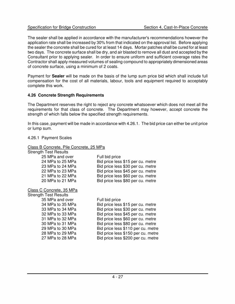
Specification for Bridge Construction Section 4, Cast-In-Place Concrete
4 - 27
The sealer shall be applied in accordance with the manufacturer's recommendations however the application rate shall be increased by 30% from that indicated on the approval list. Before applying the sealer the concrete shall be cured for at least 14 days. Mortar patches shall be cured for at least two days. The concrete surface shall be dry, and air blasted to remove all dust and accepted by the Consultant prior to applying sealer. In order to ensure uniform and sufficient coverage rates the Contractor shall apply measured volumes of sealing compound to appropriately dimensioned areas of concrete surface, using a minimum of 2 coats.
Payment for Sealer will be made on the basis of the lump sum price bid which shall include full compensation for the cost of all materials, labour, tools and equipment required to acceptably complete this work.
4.26 Concrete Strength Requirements
The Department reserves the right to reject any concrete whatsoever which does not meet all the requirements for that class of concrete. The Department may however, accept concrete the strength of which falls below the specified strength requirements.
In this case, payment will be made in accordance with 4.26.1. The bid price can either be unit price or lump sum.
4.26.1 Payment Scales
Class B Concrete, Pile Concrete, 25 MPa Strength Test Results
25 MPa and over Full bid price 24 MPa to 25 MPa Bid price less $15 per cu. metre 23 MPa to 24 MPa Bid price less $30 per cu. metre 22 MPa to 23 MPa Bid price less $45 per cu. metre 21 MPa to 22 MPa Bid price less $60 per cu. metre 20 MPa to 21 MPa Bid price less $80 per cu. metre
Class C Concrete, 35 MPa Strength Test Results
35 MPa and over Full bid price 34 MPa to 35 MPa Bid price less $15 per cu. metre 33 MPa to 34 MPa Bid price less $30 per cu. metre 32 MPa to 33 MPa Bid price less $45 per cu. metre 31 MPa to 32 MPa Bid price less $60 per cu. metre 30 MPa to 31 MPa Bid price less $80 per cu. metre 29 MPa to 30 MPa Bid price less $110 per cu. metre 28 MPa to 29 MPa Bid price less $150 per cu. metre 27 MPa to 28 MPa Bid price less $200 per cu. metre
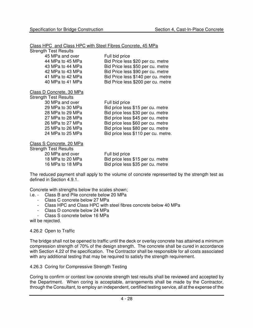
Specification for Bridge Construction Section 4, Cast-In-Place Concrete
4 - 28
Class HPC and Class HPC with Steel Fibres Concrete, 45 MPa Strength Test Results
45 MPa and over Full bid price 44 MPa to 45 MPa Bid Price less $20 per cu. metre 43 MPa to 44 MPa Bid Price less $50 per cu. metre 42 MPa to 43 MPa Bid Price less $90 per cu. metre 41 MPa to 42 MPa Bid Price less $140 per cu. metre 40 MPa to 41 MPa Bid Price less $200 per cu. metre
Class D Concrete, 30 MPa Strength Test Results
30 MPa and over Full bid price 29 MPa to 30 MPa Bid price less $15 per cu. metre 28 MPa to 29 MPa Bid price less $30 per cu. metre 27 MPa to 28 MPa Bid price less $45 per cu. metre 26 MPa to 27 MPa Bid price less $60 per cu. metre 25 MPa to 26 MPa Bid price less $80 per cu. metre 24 MPa to 25 MPa Bid price less $110 per cu. metre.
Class S Concrete, 20 MPa Strength Test Results
20 MPa and over Full bid price 18 MPa to 20 MPa Bid price less $15 per cu. metre 16 MPa to 18 MPa Bid price less $35 per cu. metre
The reduced payment shall apply to the volume of concrete represented by the strength test as defined in Section 4.9.1.
Concrete with strengths below the scales shown; i.e. - Class B and Pile concrete below 20 MPa
- Class C concrete below 27 MPa - Class HPC and Class HPC with steel fibres concrete below 40 MPa - Class D concrete below 24 MPa - Class S concrete below 16 MPa
will be rejected.
4.26.2 Open to Traffic
The bridge shall not be opened to traffic until the deck or overlay concrete has attained a minimum compression strength of 70% of the design strength. The concrete shall be cured in accordance with Section 4.22 of the specification. The Contractor shall be responsible for all costs associated with any additional testing that may be required to satisfy the strength requirement.
4.26.3 Coring for Compressive Strength Testing
Coring to confirm or contest low concrete strength test results shall be reviewed and accepted by the Department. When coring is acceptable, arrangements shall be made by the Contractor, through the Consultant, to employ an independent, certified testing service, all at the expense of the
Specification for Bridge Construction Section 4, Cast-In-Place Concrete
4 - 29
Contractor. The cores shall be taken and tested within seven days of the testing of the twenty-eight day cylinders representing the concrete in question. Where practical, three 100 mm � cores shall be taken for each strength test previously taken, and there shall be no doubt that the cores taken, and the cylinders under consideration represent the same batch of concrete. Cores may not be taken unless the Consultant's representative is present. Cores shall be tested by an independent CSA certified laboratory and in accordance with the requirements of CSA Standard A23.2-14C. The average strength of the cores as reported by the independent testing service shall constitute a test.
In cases where the concrete strength, as indicated by the cores, is higher than the strength based on the concrete cylinder results, the core results shall be used as the basis for acceptance of and payment for the concrete. If the core strengths are lower than the strength from the concrete cylinder tests, the cylinder tests shall govern.
4.27 Measurement and Payment
Payment will be made on the basis of the actual volume within the neat lines of the structures as shown on the drawings or revised by authority of the Department and Consultant, except deductions will be made for volume of concrete displaced by ducts and voids, and by timber, pipe, or concrete piles. The volume of a metre of timber pile will be assumed to be 0.08 m3. No deduction will be made for the volume of concrete displaced by steel reinforcement, expansion material or steel H-piles, nor for fillets, scoring and chamfers 600 mm2 or less in cross-section area.
When it is specified on the drawings that concrete in footings is to be placed against undisturbed soil or set in rock, and where the excavation is made wider than the neat lines of the footing as shown, the Contractor shall supply and place the excess volume of concrete at his own expense.
In the case of drilled cast-in-place concrete piles where the drilled holes are made larger than required by the drawings, the additional volume of pile concrete required to fill the enlarged hole shall be supplied and placed by the Contractor at his expense.
An interim payment in the amount of 80% of full value will be made if the concrete has been placed acceptably, and the 7 day test cylinder strength indicates that the concrete will reach the acceptance range of specified strength. Partial payment in advance of 28 day test results will not be deemed to constitute acceptance of the concrete, nor operate to limit in any way the requirements of Section 4.26 of these specifications or Section 1.2.24 of the General Specifications.
Final payment will not be made until the specified concrete finish is acceptably completed, and the 28 day strength tests show that the concrete meets the strength requirement of the specification, or indicate what deduction is to be made for under-strength concrete.
The payment for concrete shall include full compensation for the cost of furnishing all material, tools, equipment, falsework, forms, bracing, labour, curing, heating, surface finish and all other items of expense required to complete the concrete work shown on the drawings, and as outlined in the specifications.


�