section 4 normal procedures - finckaviation.com€¦ · 2 flight planning .....1 pre-flig ht i...
TRANSCRIPT

FLIGHT MANUAL
SECTION 4
NORMAL PROCEDURES
CONTENTS
4.1 GENERAL PAGE
4.2
1 FUNCTIONAL LIMITATIONS . . . . . . . . . 1
2 FLIGHT PLANNING . . . . .1
PRE-FLIG HT I NSPECTIONS
1 EXTERIOR INSPECTION . . . . . . . . . 1
2 |NTER|OR INSPECTTON . . . . . . . . . . . . . . .3
STARTING PROCEDURES
1 PRE-STARTING CHECKLIST .. . . . . . 1
2 ENGINE STARTING . , , , .4
3 POST-STARTING CHECKLIST... . . . , , . , ,7
TA)OING. TAKEOFF1 PRE.TAXIING CHECKLIST ..... 12 TAXIING - TAKEOFF .... 1
CRUISING FLIGHT1 LEVEL FLIGHT. . . . . . 1
APPROACH. LANDING1 APPROACH - LANDING ..... 1
ENGINE AND ROTOR SHUTDOWN1 ENGINE SHUTDOWN . . . . . . . .12 ROTOR SHUTDOWN .. . . . . . . . 1
4.3
4.4
4,5
4.6
4.7
DGAC APPROVED
til4.0.P6
Page 1
EC 155 81
02-20

4.8
4.9
DGAC APPROVED
E
4.0.P6Page 2
FLIGHT MANUAL
SPECIAL OPERATING PROCEDURES1 COLD-WEATHER ENGINE STARTING . . . . . . . . . . . . . . . . . . . .1
2TAKEOFFAFTERPARKINGINFALL INGSNOW. . . . . . . . . . . . . . . . . . . . . . . . . . . 1
3 TAKEOFFAND LANDTNG ON S1OpES.. . . . . . . . . . . . . . . . . . . . . . . . . . . . . . . . . . . . . . . . .1
CHECK OF ENGINE POWER MARGIN AND THERMAL MARGIN1 ENGTNE POWER CHECK ON THE GROUND... . . . . . . . . . . . . . , . . . . . . . . , . . . . , , .12 ENGTNE POWER CHECK rN FLTGHT CONDTT|ON .. . . . . . , , . . . . . . . , . . . . . . , .33 REFERENCE CHECK... . . . . . . . . . , . . . . , , , , , . , . .4
EC 155 81
02-24

FLIGHT MANUAL
sEcTtoN 4.1
GENERALThis section contains the helicopter operating instructions and procedures from flightplanning to the safe helicopter condition after landing, going through the actual flightconditions. These procedures assume normal and standard conditions. The appropriatedata of other sections are mentioned wherever applicable. The instructions andprocedures covered by this section are set forth for standardization purposes; they are notapplicable to all situations
1 FUNCTIONAL LIMITATIONSRefer to SECTION 2 for the minimum and maximum limits.
Whenever a functional limitation has been exceeded, record it in the logbook (aircraft,engine, etc.). Record the limit exceeded, the duration of exceedance, the extreme valuereached and all the additional information necessary to define the requiredmaintenance action.
NOTEFLI audio warn
IAS Time FLI value
> 4 5 k t > 1 0 s 87.7 %lmmediate 9 1 . 4 %
< 4 5 k t > 1 0 s 101 o/o
lmmediate 103 %
FLIGHT PLANNINGEach flight must be suitably planned in order to ensure safe operation and provide tothe pilot the information he will use during flight.Flight planning must take account of the limitations.Make sure that the aircraft weight and CG position are correct, by proceeding asfollows:
. Refer to SECTION 6 - WEIGHT AND CENTER OF GRAVITY.
. Check the fuel and oil weight, the useful load, etc.o Compute the total takeoff weight and that which can be predicted for landing.r Determine aircraft performance with respect to planned flight conditions.r Compute CG location throughout the flight duration. lf a fuel transfer is foreseen,
determine the conditions in which it will be possible without exceeding CGlimitations.
cauTtgt{
WHEI{ IHITIAI. CG LOCATIO$I IS FORVYARD, ?}IERE IS A RISK TO EXCEEDFORWARO LIMITATION OURIXG T}IE FLIGHT,
INITIAL CG LOCAT'ON MUSY AE ADAPTED ACCORDINGLY.
EASA APPROVED
E4.1
Page 1
EC 155 81
07-06

DGAC APPROVED
E
PAGE INTENTIONALLY LEFT BLANK
FLIGHT MANUAL
4.102-50 Page 2
EG 155 81

FLIGHT MANUAL
. Main blades and mainrotor hub........ Condition - General visual check from
ground level.. Ground power receptacle door............. Locked (if starting with battery).
2 INTERIOR INSPECTIONr Cabin......... General check (condition, freight t ied down,
seat arrangement, etc.).. Fire extinguisher and first aid kit........... ln place (safety pin snap-wired).r PRESS.STAT selector......
o Power-assisted brake accumulator...... Pressure > 100 bar (1450 psi).lf it is less, recharge the accumulator bymeans of the electric pump of theemergency system.
NOTE
lf the copilot's seat is unoccupied, check that the harness is fastened.
EASA APPROVED
E4.2
05-25 Page 3
EC 1s5 81

SECTION 4.2
PRE-FLIG HT INSPEGTIONS
l EXTERIOR INSPEGTION
FLIGHT MANUAL
4.205-25 Page 1
NOTE
lf one or more corrective maintenance tasks were required following the lastfl ight of the previous flying day, check that these tasks have been performed.
Pay particular attention to the operations marked t' * "
Check that area is clean and clear
Remove the picketing equipment where applicable (covers, blade socks,mooring l ines etc).
Perform the following checks.
Figure 1: Exterior InspectionSTATION 1
. General appearance .. . Condit ion - No traces of leakage.
o Transparent panels . . . . . Cleanl iness.
o Air intakes (MGB and engine) . . Check cleanl iness; clean i f necessary.On snow-covered ground, refer tosEcTtoN 4.9."
. Main b lades and mainrotor hub .. Condit ion - General visual check from
ground level.
Condition - No foreign object.
o
o
a
oq
CDoq
lJ)lo
(J
u{
=
EASA APPROVED
E
EC 155 Bl

FLIGHT MANUAL
. Radome ...Condition - Closed and locked.r Nose landing 9ear. . . . . . . . . . . . . . . . . . . . . . . . . . . . . . . . .V isua1 examinat ion.. Bat tery compartment door . . . . . . . . . . . . . . , . . . . . Locked.
STATION 2
. Main blades and mainrotor hub .. Condition - General visual check from
ground level.
. Hydraulic reservoir........ ..Level.
. Engine oil tank ................ Level (max oil consumption: 0.2 l/h).
. Cowlings (MGB and engine) .................C|osed - Locked.o Fuel tank fi l ler caps............................... Closed - Locked. Compartment door
locked after checking plugs.
' L/G units ...Visual examination.. F i re ext inguisher . . . . . . . . . . . . . . . . . . . . . . . . . . . . . . . . . . . Pressure correct .r Static ports.............. ........Condition - No foreign object.o Luggage compartment ...door closed (if installed).. Engine exhaust no221e. . . . . . . . . . . . . . . . . . . . . . . . . . No fore ign object .
STATION 3
r Horizontal and vertical stabil izers .........General condition.. Shrouded tail rotor......... . No chafing of blades on
structure. Condition of blades: leading edgesand root in particular.
. TGB . . . . . . . . . .Leve1.
o Tail skid..... No distortion.STATION 4
. Tail gearbox cowlings .....Closed and locked.r Static ports.............. ........Condition - No foreign object.o Engine exhaust no221e.......................... No foreign object.. Fire extinguisher...................................Pressure correct.(lf pressure gauge fitted).. Luggage compartment ... Loads lashed, door closedo L/G uni t . . . . . . . . . . . . . . . . . . . . . . . . . .V isua| examinat ion.
r Cowlings (MGB and engine) .................C|osed - Locked.
. Engine oil tank ............... Level (max oil consumption: 0.2 yh).
. Hydraulic reservoir........ ..Level.
EASA APPROVED
E4.2
05-25 Page 2
EC 155 81

FLIGHT MANUAL
SECTION 4.3
STARTING PROCEDURES
1 PRE.STARTING CHECKLISTCheck the fol lowing points:1. Doors . Closed and locked.2. Seats, Yaw pedals . Adjusted.3. Seatbelts and harnesses.. . . Fastened.4. Circui t breakers . . . . . . A l l engaged.5. Switches:
L G P U M P . . . . N O R M .HYD ISOL . . NORM.SHEDBUS. . . AuTo. (guarded) .RPM NORM.TNG . . FLT.NORMAL/BACKUP. . NORMAL (guarded).ENG 1 and ENG 2 , . . . OFF .Others . . . . . A l l OFF.S/B HRZ . . . . . ON - L igh t on .
6. BAT/ESS . . . ON.
Check: I BAT IVoltmeter reading. . . . . . Checked > 23 V .
NOTEWhen a ground power unit is plug in: ]f l
Power application starts the self-test of the engine computer.
upon completion of thetest, check: @ and @
NOTEOAT value may not be available on the VEMD during self test of the system.
f f iUponse| f testcomp|et ionscro| | tosystemstatuSpageandcheckthedisplayed failure message :
. TO.DISC A or B : Difference of more than 5" C between the two fadec thermal probedue to sun exposure.
Continue start up procedure. Before take off check that the temperatures difference isless than 15' C, othenivise cancel take-off and report to Maintenance Manual.
o Any other message : Abort start up procedure and report to Maintenance Manual.
EASAAPPRoVED Ec 15s 81 4.9
E 04-07 Page 1

FLIGHT MANUAL
NOTE
o OEI Hl usage is avai lable in the system status page (see S 4 7)
9.1 0 .1 1 .12.
orroncAD@+anY"tEGi l@
r@@App|yappropr ia temaintenancebeforestar tup.
7. Br ightness, PFD and ND. .Adjusted.
8. Heating and venti lat ion controls . . . . Off.Fuel shutoff control levers . Fonruard and snap wired. Red light out.Rotor brake control .... Released, fully fonrvard.Posit ion l ights ON (i f necessary).Anti-col l is ion l ight . ON.
NOTE
For aircraft fitted with single emergency battery, ARM positionallows to energize standby horizon by main battery.
14. Passenger's ordinance lights .............. ON (if passenger on board).15. Indicator l ight test function ..................Test (to be performed on DAY position ONLY)1 6. Inst rument 1 i9ht in9. . . . . . . . . . . . . . . . . . . . . . . . . . . . . . . As requi red.17. Vent se lector . . . . . . . . . . . . . . . . .OFF.18. Miss ion selector . . . . . . . . . . . .OFF.19. Emergency locator transmitter
[J::jill]';;.:.:.:.......::...:.::..::::.:...:..|i*'@L/G PUMP. . . . . .TEST (Do not exceed a durat ion of 2 min.) .Control travel l@"1 .. . . . Checked.Controls.. . . Centered (AP ON then OFF to use centering
function if needed).24 . L IG PUMP. . . . . . NORM.25. TEST SERVO . . . . . . .When pressing the push-but ton, check:
26. TRIM FEEL . . . . . ON27. GEN 1, 2 and ALT (if installed) ..... ON28. EMERGENCY CUT OFF .. Fonvard and snap wired.
4.3Page 2
20.21 .22.23.
EASA APPROVED
rEC 15s 81
07-06

7.8 .9 .
1 0 .1 1 .
FLIGHT MANUAL
NOTE
r roncAD@+anY",@Gil@
@@App |yapp rop r i a tema in tenancebe fo res ta r tup .
Brightness, PFD and ND . Adjusted.Heating and ventilation controls ... Off.Fuel shutoff control levers .... Fonruard and snap wired. Red light out.R o t o r b r a k e c o n t r o t . . . R e | e a s e d , f u | | y f o n r u a r d f f iPosition l ights .... ON (if necessary)
1 2. Ant i -co l l is ion 1 i9ht . . . . . . . . . . . . . . . . . . . . . . . . . . . . . . . . ON.13. Passenger's ordinance |ights.............. ON (if passenger on board).14. Indicator l ight test function.................. Test (to be performed on DAY position ONLY)15. Emergency l ighting system................. Test performed, then ARM.16. Instrument l ighting ........ As required.17. Vent se lector . . . . . . . . . . . . . . . . OFF.1 8. Miss ion selector . . . . . . . . . . . . . . . . . . . . . . . . . . . . . . . . . . OFF.1 9. Emergency locator transmitter
( i f insta l led) . . . NORM.20 . Aud io wa rn ing . . . . . . ON.21 . LIG PUMP . . . TEST(Do not exceed a durat ion of 2 min.) .22. Control travel l7,M'fii| .. Checked.23. Controls Centered.
24 . L IG PUMP . . . NORM.25. TEST SERVO.. . . When pressing the push-but ton, check:
26 . TR IM FEEL
27. GEN 1 ,2 and ALT (i f instal led)
28 . EMERGENCY CUT OFF
ONONFonruard and snap wired.
CAUTION : THIS PAGE MUST NOT BE REMOVED FROM THE MANUAL UNTIL MODIFICATIONAMS No. 07-71C16 (TU 93C) HAVE BEEN EMBODIED TO THE AIRCRAFT.
EASA APPROVED
E
4.3Page 2
*RC"
EC 155 81
06-14

FLIGHT MANUAL
29. Engine f ire system test . . . . . Check both posit ions.
I FrRE I (overhead panet),
(Red warning Panel) ,
red light (fuel shutoff control lever) on and(instrument panel) f lashing.
@ (detection failure) on overhead panel.
30. Cargqiystem test Check both positions
IF,AEJ+ @+t-ERE-t+ lwARNl
@ (detection failure) on overhead panel.
31 . S tandby magnet ic compass . . . . . . . . . Checked.32. Light i l luminated at
Red Warn ing Pane l . . . . . . . . . . Check
f lash ing.
R H + L H See NOTE item 3633. Clock Wound and set.34. Alt imeter . . Set.35. Gear ... Down with safety pin
removed.36. Fuel management panel :
Test. . . . . . Fuel level at 0 on CADTransfer pump . Tested (green arrow +
characteristic noise).For each booster pump .. . . . . Check pressure > 0.4 bar
NOTE
lf feeder tank are not full, the
l ights may come on. lt will go out only when jet pumps have filled the feeder tank.
37. Parking brake . Applied.38. Nose wheel castoring lock. ..... As required (if fitted).
EASA APPROVED
r4.3
Page 3
EC 155 Bl
05-25

FLIGHT MANUAL
2 ENGINE STARTING
{i,,&u":L$Y"&ffi4
ffiw&ffiffiw'ww ffiw maffi %ry w{;w u"% ew w&wu#wM wgruw &bew ryw*wffiMffiffisw W&TffiW WffiM %WXqMffi T*q LW WTTW{ WUMffi, W
www w%,sw Twffi ffiryswffiMffi *ffi wwww&q#w"&ffi www uffi "&ffi ffi?&wwutffiffi|b-,e wa&w? Tffi Txtr{ w*&q:Te&&"&3"
lf AP version permits, the following pitch centering procedure allows to centerautomatically cyclic stick:
1. LG PUMP . . . . . .TEST
2 . 4P . . . . . . . . . . . . . . . . . . . . . . . . . . . . . . . . . . . . . . . . ON
3. Cyclic........ ..... Free
4. Centering button (upper mode release)..... Pressed more than 2 s (cyclic moves toneutral position)
5. AP. . . . . . . . . . . . . . . . . OFF
6. LG PUMP . . . . . NORM
NOTE. When OAT 5 0"C: ln case of aborted start, when TOT > 120"C, perform a cranking
operation before attempting another start.o Engines may be started in any order.o For OAT S 0"C start up procedure is identical as $ 2.1 but "FLT/IDUOFF" switch
must be held on 'lDL" until engine oil temperature reaches:- 0"C for 5 cSt oil.- -10"C for 3 to 3.9 cSt oil.Then select the "FLT/IDL/OFF" switch to "FLT".
2.1 STARTING lST ENGINE
1. NORMAL/BACKUP ....NORMAL.
2. ENG.. . . . . . . . . . . . . . . . . . . . . . . . . . .F1T.r Check battery voltage: if < 17 V, stop starting sequence (battery insufficiently
charged).o On engine concerned, or VEMD:
oEl
EASA APPROVED
E4.3
Page 4
EC 155 Bl
07.06

FLIGHT MANUAL
C A U T I O H
A B O R T T H E $ T A R T I I I I G P R O C E D U R E B Y S E T T I H G T H EETTIG # SWITCH TO OFF IF :- I G N I T I O N l $ H O T E F F E C T I V E A F T E R 3 O s .. T H E T O T i l U M E R I C A L V A L U E I S U H D E R S C O R E Do r. T H Eo r- T H E
L I G H T l $ S T I L L O l r l A T H { = T O Y \
ROTOR DOES NOT RUH AT i l { = I 5A /o
: 'o r. I F F R E E T U R B I N E S P E E D P O I H T E R M O V E S B E Y O H D R O T O R$ P E E D P O T H T E R O N T R T P L E I H D I C A T O R ( F R E E W H E E L | ! { G } .
f ENGIt_. JI rFr'/E If Moe)t._J
o Audio warning sounds when NR is between 165 and 330 rpm.o Check I FrRSI LH or RH.
3. Safety device ... .. In position.
CAUTION
!N ORDER TO PREVENT OVERHEATING OF THE STARTER.GENERATOR, DO NOT ATTEMPT IUIORE THAN 5CONSECUTIVE ENGINE STARTS OR CRANKING CYGLES.AFTER 5 UNSUCCESSFUL ATTEMPTS, WAIT 20 MINUTESBEFORE TRYING AGAIN.
and | "iEtll I LH or RH, N1 s To%
LH and RH and I t$EFrVCI | at N2 < 80 rpm (equivatent NR).
at N2 < 120 rpm (equivalent NR).
EASA APPROVED
r
I4.3
Page 5
EC 155 81
0746

FLIGHT MANUAL
2.2 STARTING 2ND ENGINE
. Proceed as for 2.1 , except for disarming of the OEI stops.
Check that triple indicator pointers (NR, N2) are superimposed.
Check:
-I E N G I| * ; and I 6El'1il RH or LH, N 1 s1oo/o.\-----J
Check that the VEMD is switched to the AEO mode when N1> 60%.
Check
2.3 CRANKING
EASA APPROVED
E
and t rrrt$ | RH or LH
l
The cranking procedure can be performed for verification purposes.
Proceed as follows:
o Check:
ENG # . . . . . . .OFF.
NORMA1JBACKUP. ....NORMAL.
o Booster pumps .. . . . . . . . .ON.
o CRANK . . . . . . . . . . . . . . . . . . , . . . . . . . . .20 s maximum.
CAUTION
DO NOT CRANK THE ENGINE UUITH THE TSANUAL FUELSHUTOFF VALVE CLOSED AS THIS COULD DATIIAGE THEENGINE FUEL PU]tiP.
4.3Page 6
EC 155 Bl
05-25

FLIGHT MANUAL
3 POST.STARTING CHECKLIST
3.1 OVERALL CHECKS
1. Ground power unit .. Disconnected.2. Exterior lights .. As required.
NOTE
ln some operational circumstances (clouds, dark night or others),the white strobe (if fitted) may disturb the pilot.
Switch to red position if needed.
3. Windshie ld wiper selector . . . . . . , . . . As required.
4. HeatingA/enti lat ion . As required.
5 . P I T O T 1 , 2 a n d E M E R P l T . . O N .
6. Tail rotor servocontrolisolat ion test . . . . . Performed.
HYD. ISOLATE. . . CUT OFF:
@RHthen EEfIElHYD.ISOLATE.. . . . NORM:
I trt'fq tEV I RH and
8. Electr ical parameters .. . . . Checked.g .ch ip tes t Per fo rm"o .@or@
10. Caut ion Advisory Panels . . . . . . A l l l ights out .
1 1. Temperature and pressurereadings . . . . . . Checked.
12. Engine and f l ight instruments .. . . . Checked.
13. Engine fuel low pressure sensortest . Performed.
. Booster pump . . . . . A l l OFF, check
. Booster pump . . . . . A l l ON.LH + RH.
NOTElf the copilot's seat is unoccupied, switch off the left screens.
EASA APPROVED
r4.3
Page 7
EC 155 Bl
05-25

FLIGHT MANUAL
3.2 SPECTAL CHECKS (F|RST FLtcHT OF THE DAy)3.2.1 P2 Valve and Heating System automatic switch-off test
1 . VENT selector . . . . . . . . HEAT.
2. Heating control . ......Aft.
3. Check heating system .. . . . . . . . Off .
4. Engine associated withthe valve to be tested . . . . . . . . . IDL# (TNG mode).
5. Heating control .Fonrvard: check heating system on.
6. Check that the T4 temperature of the normally operating engine increases morethan 15"C.
NOTEl f the T4 temperature does not increase, the P2 valve of the idl ing engine is probablyseized in the open position. Confirm the failure by applying the same procedure with
collective pitch increased (same check with P2 valve increased)
lf SoV CUT test fails, automatic heat Jil=*r switch off will not operate in case ofengine fai lure
8. Perform the same check on the other engine.
3.2.2 Test of Autopilot- Co l lec t i vep i tch . . .Un locked.
- Hands and feet. ... off.
- BEEP TRIM . . . . . . . . Check .
- A P o F F @- Test ..oN I oN I ftashes.
EASA APPROVED
r4.3
07-06 Page 8
EC 155 Bl
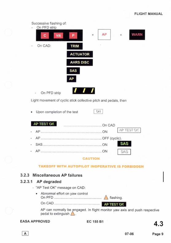
Successive- On PFD
EASA APPROVED
r
f lashing of:stri
pi tch and pedals, then
@
FLIGHT MANUAL
4.3Page 9
+EOn CAD:
- On PFD str ip
Light movement of cycl ic st ick col lect ive
o Upon completion of the test
3.2.3 Miscel laneous AP fai lures
3.2.3.1 AP degraded
@@@EEIm
- "AP Test OK" message on CAD:
. Abnormal effort on yaw controlOn PFD I nash ing .
On CAD
AP can normal ly be gngaged. ln f l ightpedal to ext inguish A
monitor yaw axis and push respective
EC 15s 81
07-06

FLIGHT MANUAL
No "AP Test OK" message on CAD
o Yaw tr im fai lure
On CAD
On PFD
On CAD
On PFD
Switch off the collective button on overhea el . AP can be engaged. The4 axis is not operative.
o Minor AP fai lure
On AP box . . . . .Test
EASA APPROVED
r
f lashes.
on relevant axis.
not be used. Att i tude hold only.
on PFD tro'Fon AP box .n t r im.y . @AP must not be used(only SAS function on cyclic).
. Loss AP module
On AP box .. . . .Test tq steady and
o n P F D @ @ @AP can not be engaged.
o Loss of actuator
On AP box . . . . . . .Test steady and
On CAD
4.3Page 10
on AP box . . . . .A t r im yaw @AP can normally be engaged. In f l ight monitor yaw axis and push respectivepedal to ext inguish; \
o Collective trim failure
trd pan
On PFD
AP can be engaged. Upper mode can
3.2.3.2 AP inoperative
)";:J;ffiffi:"'ncAD:On CAD
On PFD
AP can not be engaged.
EC 155 Bl
@
07-06

FLIGHT MANUAL
sEcTtoN 4.4TAXIING . TAKEOFF
1 PRE.TAXIING CHECKLIST1. Radioaltimeter. .. ON - Tested - DH set.2. Radionavigation systems .... Set and tested.3. Radiocommunication systems. ... Set and tested.4. Collective pitch lever ..... Released.5. Pressure and temperature readings.. . . . . . Normal.6. Warning l ights .. . All out.7. Autopilot ON.
. lf on PFD strip
- AP / SAS... .... RESET.- Autoplot : : : . : : : : : : : : : : : : : : : : : . . . . . . . . oN
8. Heating and ventilalion As required.9. Parking brake............. Released.
10. Nose wheel castoring |ock............ Release (if necessary).
2 TAXIING . TAKEOFF2.1 TAXIING
r Increase collective pitch, then move cyclic stick forward moderately to initiate low-speed taxiing.
r Brakes, (collective pitch set tofull low pitch)............. Checked.
r Attitude indicators stability.......... . Checked.o Headings... Checked.o Steer the aircraft with the yaw pedals and not the wheel brakes, which are
normally used only to slow down and stop the aircraft.
ChVTt*f,4
r lF I LMT l+ GQruG RECEr{T f f t " rq f . CYCLTC STTCK^
8 *N GR*LlNfr, t f 'L *nvnfr, T0 WW.*VX?4T hfiY RISK Qf VYP,T\C.P,LOSCILLATWru$, TH€ TRIM Lff ihNS W'UST BT RELHA$ED tsY*T?RT"S*'N& THT CQL"LT.CT'V* TN'T& RNLXESE TruG*Xfr,wHr"r[EvY.R TWffi COLL.#.CT\\, /*. Lr\try"ff i 'S Wff iVrm.
EASA APPROVED
E4.4
Page 1
NOTE
EC 155 81
07-06

FLIGHT MANUAL
2.2 TAKEOFF AND HOVERING. Warning and caution lights ..All out.o Engine parameters .. Normal.o Heating .. Switch off.o Enter hover IGE at 6 ft.
NOTE
may appear temporary on the PFD
Check:
r All warning and caution lights out.
r Pressure and temperature readings normal.
o Take off while adjusting the collective pitch so as to maintiain constant height up to30 kt (55 km/h), then allow the aircraft to climb.
r Reduce power below MTOP before reaching 40 kt (74 kr/h)
cAunoN
THE TAKEOFF PATH TUST RETAIN OUTSDE THEHEIGHT'VEI.OCITY DIAGRATI DEFINED IN SEGTION 2.
o Retract landing gear at Vy.
2.3 CLIMBINGo Gear Retracted.
The best rate of climb speed (Vy) is 80 kt (TAS).For practical purposes, it will be assumed here that Vy(lAS) = 80 kt (148 km/h) less 1kt per 1000 ft of altitude (3 km/h per 500 m).
o Heating..... .............As required.
NOTE
The climb is done with about 2' bank right.
i r
l .
EASA APPROVED
E4.4
07-06 Page 2
EC 155 Bl
FLIGHT MANUAL
sEcTroN 4.5CRUISING FLIGHT
1 LEVEL FLIGHT
1.1 CRUISING FLIGHT
. Maximum endurance is obtained by flying at Vy (refer to para. 2.3 - section 4.4).e Balance fuel quantities in left and right tanks as soon as possible while
respecting CG limits (Transfer pump flow = 280 kg/h (a50 pph)).
1.2 MANEUVERINGAvoid sudden maneuvers causing the load factor to be reached abruptly.
o At weight > 4400 kg, do not hold turns beyond 45'bank.
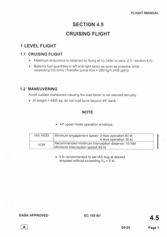
NOTE
. AP upper mode operation envelops.
o lt is recommended to set IAS bug at desiredairspeed without exceeding VH + 5 kt.
EASA APPROVED
E4.5
05-25 Page 1
IAS; HDG Minimum engagement speed:3 Axis operation 60 kt4 Axis operation 30 kt
VOR Recommended minimum interception distance: 10 NMMinimum interception speed: 60 kt
EC 155 Bl

FLIGHT MANUAL
1.3 FLYING IN TURBULENCEReduce lAS.
1.4 HEATING . DEMISTING - VENTILATION
NOTE
o LH control in forward position disable individual nozzle.(lf control not fitted, individual nozzle bleed are always available).
. Center control in forward position allows recirculation and increases heatingefficiency. Prolonged use of this position on ground is not advised.
. After AMS 07 2'l'B99: closing of lower pilot and copilot diffusers increase demistingefficiency.
1.4.1 Heating - Demisting1. Selector button ............ ... Press.2. Selector. . . . . . . . . . . . . . . . . . . . . . . . . . HEAT.3. LH control (if fitted)......... As required.4. Center contro|........... ...... As required.5. RH control As required for heating
regulation.
In case of ECS automatic shut off :. On CAD. RH control .. Slightly reduced. Wait for automatic switch on
+@lof P2 bleed . I EcS I
NOTE
On engine failure P2 bleed is automatically switched off when exceeding the OEIcontinuous rating on N1. Reset the system by push-button on rotary selector
if needed (for Nl rating < OEI continuous).
1,4.2 Venti lation1. Selector VENT.2. Controls All two or three aft.
EASA APPROVED
E
4.507-06 Page 2
EC 155 81

FLIGHT MANUAL
sEcTtoN 4.6APPROACH - LANDING
1 APPROACH - LANDINGPassenger 's ord inance | ights. . . . . . . . . . . . . . . . . . . . . . . . . . . . . . . . . . . . . ON.
Extend the landing gear and check the following:
1. Gear.......... Down and locked.
2. Light .... As required.
3. Nose wheel castoring |ock............. .. As required.
4. Parking brake............. Released.
5. Caution, warning and instrumentreadings Checked.
6. Heating..... Switch off.
The descent path must remain outside the risk zone specified on the heighUvelocitydiagram (refer to SECTION 2).
. For IFR coupled approach at minima when in sight.7. Upper mode ............. . Disengaged.
NOTEAP upper mode operation envelops.
VOR.A Recommended minimum interception distance: 5 N.M.
LOC/GS Recommended minimum interception distance: 5 N.M.Recommended interception angle< 60".
CAUTION
ON GRfJ-UND, IhI ORDEre TA PRTVENT ANY RI$K OF VHRTICALOSCILLATIONS, THE TRIM LOADS MUST BE RELEASED BYDEPRE$$ING THN COLLECTMT. TRIM RELEA$E TRIGGERWHNNEVVft,TI |E CALLECT'VY LEVtr .R IS MSVED
EASA APPROVED
r4.6
07-06 Page 1
EC 155 81

FLIGHT MANUAL
SECTION 4.7
ENGINE AND ROTOR SHUTDOWN
1 ENGINE SHUTDOWN. Wait for 30 s before shutting down engines. The taxiing duration can be subtracted
from these 30 s.
1. Controls Centered (use AP centerinofunction if available).
2 . 4P . . . . . . . . . . . . . . . . . . . . . . . . . . OFF .3. Collective pitch lever...... Locked.4. Pitots - Audio warning - Landing 1i9h1................. OFF.5 . ENG 1 and ENG 2 . . . . . . . . . . . . . . . . . . . . . . . IDL then OFF .6. Booster pumps. . . . . . . . . . . . . . . . . . . . . . . . . . . . . OFF.
NOTElf the engine does not stop immediately (Solenoid valve failure),
the FADEC will shut down the engine 5 to 6 s later.Do not pull the fuel shutoff control lever before 1 0 s have elapsed.
2 ROTOR SHUTDOWNGAUT!ON
ROTOR BRAKE APPLIGATION IS PROHIEITEDBEFORE ENGISIE SI.IUTDOW}I.
r At NR < 120 rpm.
1. Rotor brake. . . . . . . . . . . . . Appl ied.2. Radio - Radio Nav. . . . . . . . . . . . . . . . . . . . . . . . OFF.3. S/B HRZ.. . . . . . . . . . . . . . . . OFF.
. When the rotor is stopped
1. Switches All OFF (except HYD ISOL).2. VEMD fl ight report page information.................. Check.3. VEMD system status page... ........ Scroll to check OEI usage (report
to engine maintenance manual ifneeded).
4. BAT/ESS.. . . . . . . . . . . . . . . OFF.
NOTh,At shutdown do not open the front doors before complete stop of the rotor.
EASA APPROVED
til4.7
07-06 Page 1
EC 155 81

FLIGHT MANUAL
SECTION 4.8
SPECIAL OPERATING PROCEDURES
1 COLD-WEATHER OPERATTONS (-40"C < OAT < -15"C)Helicopter fitted with extreme cold weather kit (refer to 2.3 page 3) are allowed tooperate with -40'C < OAT < -15"C.
NOTE
IF AIRCRAFT IS PARKED FOR AN OAT < -25"C
1) Refer to Aircraft Maintenance Manual : applicable document 05-21-00-218
2) lt OAT < -30'C, remove the battery and store it in a warm place.
2 TAKEOFF AFTER PARKING IN FALLING SNOWBefore starting the engines, check (opening MGB cowlings if necessary) that there isno snow or ice built up inside the air intake ducts.
Carefully remove any trace of snow from the grid, around the air intakes, from thecowlings and top of fuselage
3 TAKEOFF AND LANDING ON SLOPES3.1 TAKEOFF AND LANDING.ON.SLOPE ENVELOPE
See section 2.6 page 1
3.2 TAKEOFFo Before takeoff:
- Park ing brake. . . . . . . . . . . . . . . . . . . . . . . . . . . . . . . . . . Appl ied.- Nose wheel ............ ... Locked.
. After takeoff:- Park ing brake. . . . . . . . . . . . . . . . . . . . . . . . . . . . . . . . . . Released.- Nose wheel . . . . . . . . . . . . . . . Unlocked.
3.3 LANDINGo Before landing:
- Parking brake............. Applied.- Nose wheel . . . . . . . . . . . . . . . . Locked.
r Before fully reducing collective pitch, move cyclic stick to neutral position
to prevent I Lllffl light from coming on.
EASA APPROVED
E
4.905-25 Page 1
EC 155 81

FLIGHT MANUAL
SECTION 4.9
ENGINE POWER AND THERMAL CHECK
1 GENERAL
The purpose of the engine power check is to determine the available power margin andthermal margin relative to the minimum guaranteed engine.
The periodicity of this test must be in accordance with applicable operational regulation.The time interval between two checks must not exceed 20 flight hours.
Those check can be done in three different configurations:
On oround: Power or thermal check can be done on ground, but the stability neededis otten ditficult to obtain. This test has to be considered as indicative. In any case ofdoubt, a check in flight has to be done.
In cruise fliqht at MCP: This is the most useful test condition. The test can be donein normal twin engine cruise flight at around 140 Kt.
In Trainino OEI level flioht: This test is considered as reference test because it isdone in single engine condition and therefore allows to use high N1 and TOT. lt is tobe performed to confirm a bad or questionable result obtained in the twin enginetest power or thermal check.
The engine power and thermal check can be done :
Automatically by FADEC and VEMD by pressing SCROLL on VEMD, or
Manually by comparison with reference data, by entering the parameters recordedon the corresponding chart.
NOTE
o The result of the automatic power check is referenced to the 100% of each engine.To compare it to manual power check result, it is necessary to divide it by two.
r For the same reason in the parameters displayed by VEMD after power check, thetorque has to be divided by two.
DGAC APPROVED
til
4.902-50 Page 1
EC 155 81

FLIGHT MANUAL
1.1 AUTOMATIC POWER AND THERMAL CHECK PROCEDURE
. Press the scroll button on VEMD to start the EPC.o Positive results are satisfactory.
r lf any result is negative, corresponding engine may be defective.
NOTEThe filling of the white rectangle gives an idea of the timing.
At the end of the test the VEMD displays the results of power and thermal check orone of the following message :
: Stability was not achieved with enoughaccuracy. Start another EPC.
: Failure of one parameter. Proceed to amanual check.
1.2 MANUAL POWER CHECKThe corrected torque value is determined on corresponding chart and has to becompared with the recorded torque.
- lf the recorded torque is higher than the corrected torque, the result issatisfactory.
- lf recorded torque is lower than the corrected torque : engine may be defective.
1.3 MANUAL THERMAL CHECKThe corrected TOT value is determined on corresponding chart and has to becompared with the recorded TOT.
- lf the corrected TOT is higher than the recorded TOT, the result is satisfactory.- lf the corrected TOT is lower than the recorded TOT: engine may be defective.
2 ON qROUND ENGINE POWER AND THERMAL CHECK
NOTEr lf questionable or unstable results are obtained, it is advisable to repeat the test
procedure at ditferent N1 values.o lf any result is unsatisfactory, proceed with an in flight power check.
DGAC APPROVED
E
4.9Page 2
EC 155 81
02-50

FLIGHT MANUAL
The paragraph 2.2 is modified as follows:
2.2 AUTOMATIC POWER AND THERMAL CHECKo Press the scroll button on VEMD to start the EPC.o Positive results are satisfactory.o The result of the automatic thermal margin check must be corrected as follows:
TOT margin = TOT margin displayed by VEMD + DTC.
After the correction if any result is negative, corresponding engine may be defective.A check in fl ight has to be performed.
CAUTION : THIS PAGE MUST NOT BE REMOVED FROM THE MANUAL UNTIL MODIFICATIONAMS No. 07-71C16 (TU 93C) HAVE BEEN EMBODIED TO THE AIRCRAFT.
EASA APPROVED
E4.9
06-14 tifl"":
Hp(ft) 0 1 000 2000 3000 to 4000 5000 6000 to 8000 9000 to 13000 14000 to 15000
DTC("c) 1 6 1 4 12 1 1 1 0 I 8 7
EC 155 81

FLIGHT MANUAL
2.1 RECORDING CONDITIONS
The check is to be performed :r Head the aircraft into the wind on a clear area.r After starting both engine, set one engine to IDLE/TRAINING.o Switch ott all P2 bleed air flow.r Raise the collective pitch lever to obtain the maximum available power (from the
engine which is not in IDLE TRAINING mode) at the limit of liftoff, without allowingrotor speed to drop below 342 rpm.
o Check that the bleed valve is closed and that parameter readings are stable.r For manual power check, record following values on the engine in TRAINING
mode :- engine torque : Tq (%).- exhaust gas temperature : TOT ("C).- gas generator speed : Nl (%).- rotor speed : NR (rpm ).- pressure altitude : Hp (ft).- outside air temperature : OAT ("C).
. Apply the same procedure for checking the other engine.
2.2 AUTOMATIC POWER AND THERMAL CHECKr Press the scroll button on VEMD to start the EPC.. Positive results are satisfactory.
lf any result is negative, corresponding engine may be defective. A check in flighthas to be performed.
2.3 MANUAL POWER CHECK. The corrected torque value is determined on Figure 1 chart and has to be
compared with the recorded torque.- lf the recorded torque is higher than the corrected torque, the result is
satisfactory.- lf the recorded torque is lower than the corrected torque: engine may be
defectiveA check in flight has to be performed.
2.4 MANUAL THERMAL CHECKr The corrected TOT is determined by using figure 2 and has to be compared with
the recorded TOT.- lf the corrected TOT is higher than the recorded TOT, the result is satisfactory.- lf the corrected TOT is lower than the recorded TOT: engine may be defective.
A check in flight has to be performed.
EASA APPROVED
E
4.907-06 Page 3
EC 155 81

FLIGHT MANUAL
3 IN CRUISE FLIGHT ENGINE POWER AND THERMAL CHECK
3.1 RECORDING GONDITIONS
o P2 bleed air f1ow........... .. Shut off.o Stable cruise at 140 kt............ Maintain for three minutes.
NOTElf the configuration do not allow to maintain level flight at 140 kt, it is possible to do this
check at 100 kt.r For manual testing record the following values :
- engine torque : Tq (%).- exhaust gas temperature : TOT ("C).- gas generator speed : N1 (%).- rotor speed : NR (rpm).- pressure altitude : Hp (ft).- outside air temperature : OAT ("C).- aircraft airspeed : IAS (kt).
3.2 AUTOMATIC POWER AND THERMAL CHECK
Stabilize level flight, switch off all P2 air bleed and press scroll button on VEMD tostart the EPC.
lf any result is negative, corresponding engine may be defective. A reference checkin training OEI level flight has to be performed (94).
3.3 MANUAL POWER CHECK
Determine the corrected torque value by using Figure 4 (140 k0 or Figure 5 (100 k0.lf the recorded torque is higher than the corrected torque, the result is satisfactory.lf not, confirm these values by performing a reference check in training OEI levelflisht ($4).
3.4 MANUAL THERMAL CHECK
Determine the corrected TOT by using Figure 2 or 3.lf the corrected TOT is higher than the recorded TOT, the result is satisfactory.lf not, confirm these values by performing a reference check in training OEI levelflisht ($a).
EASA APPROVED
iil
4.906-14 Page 4
EC 15s 81

FLIGHT MANUAL
The paragraph 3.2 is modified as follows :
3.2 AUTOMATIC POWER AND THERMAL CHECK
Stabilize level flight, switch off all P2 air bleed and press scroll button on VEMD tostart the EPC.. The result of the automatic thermal margin check must be corrected as follows:
TOT margin = TOT margin displayed by VEMD + DTC.Hp
(ft) 0 1 000 2000 3000 to 4000 5000 6000 to 8000 9000 to 13000 14000 to 15000
DTC('c) 1 6 1 4 12 1 1 1 0 I 8 7
After the correction if any result is negative, corresponding engine may be defective.A reference check in training OEI level fl ight has to be performed (S4).
CAUTION : THIS PAGE MUST NOT BE REMOVED FROM THE MANUAL UNTIL MODIFICATIONAMS No. 07-71C16 (TU 93C) HAVE BEEN EMBODIED TO THE AIRCMFT.
EASA APPROVED
til
4.906_14 'in*""l
EC 155 Bl

FLIGHT MANUAL
The paragraph 4.3 is modified as follows :
4.3 AUTOMATIC POWERAND THERMAL CHECKo The result of the automatic thermal margin check must be corrected as follows:
TOT margin = TOT margin displayed by VEMD + DTC.
lf any result is negative, refer to Engine Maintenance Manual.
CAUTION : THIS PAGE MUST NOT BE REMOVED FROM THE MANUAL UNTIL MODIFICATIONAMS No. 07-71C16 (TU 93C) HAVE BEEN EMBODIED TO THE AIRCRAFT.
EASA APPROVED
E4.9
06-14 tH.:
Hp(ft) 0 1 000 2000 3000 to 4000 5000 6000 to 8000 9000 to 13000 14000 to 15000
DTC("c) 1 6 1 4 12 1 1 1 0 9 8 7
EC 155 Bl

FLIGHT MANUAL
4 IN TRAINING OEI LEVEL FLIGHT ENGINE POWER ANDTHERMAL CHECK: REFERENCE CHECK
4.1 CHECKINGPRINCIPLESThis check must be carried out if one of the previous result is not satisfactory.The purpose of this in-flight check is to determine the margin of the engine at higherNl than during the previous check.
4.2 RECORDING CONDITIONSo P2 bleed air f low ............Shut off.o Training mode.............. ..Select.o OEI rat ing. . . . . . . . . . . . . . . . . . . . . . .H| .o Level f l ight at 100 kt . . . . . . . . . . . . . . . . . . . . . . . . . . . . .Mainta in.. RPM:340 rpm.. . . . . . . . . . . .Mainta in.
NOTE
Training mode is not damaging for engine, it can be maintained without time limitation.
4.3 AUTOMATIC POWER AND THERMAL CHECK
lf any result is negative : refer to Engine Maintenance Manual. II
4.4 MANUAL POWER CHECKDetermine the corrected torque value by using Figure 5 (100 k0.lf the recorded torque is higher than the corrected torque, the result is satisfactory.lf not, refer to Engine Maintenance Manual.
4.5 MANUAL THERMAL CHECKDetermine the correcled TOT value by using Figure 2 (100 k0.lf the corrected TOT is higher than the recorded TOT, the result is satisfactory.lf not, refer to Engine Maintenance Manual.
CAUTION
WIIEN TI{E REFEREIICE CHEGK IS DOIIE FOLLOWING ANUNSATISFACTORY RESULT OF IN FLIGIIT ENGINE POWER
CIIECK,IF THE RESULT OF TI{E REFERENCE CIIECK ISSATISFACTORY, Tr{E CORRESPOND|ilC ENcmE CAN BEKEPT IN SERVICE WIT1I APPROPRIATE TIAINTENANGE
(REFER TO MA|I|TENANGE mANUAL).
EASA APPROVED
E4.9
06-14 Page 5
EC 155 Bl

FLIGHT MANUAL
5 0
4 0
930F 2 0
o
O A T = 1 5 "
N 1 = 98o/o
N R = 3 4 6 r p m
H p = 3 o o o f t
1 0
GT + AT
T = 4 7 , 2 - 1 , 4 = 4 5 , 8
T o b e c o m p a r e d w i t hreco rded T-30
-40
6 0
;v 5 5
I.JJ3gE.oF 5 0act)O G TE,
o4 5
qoult3q@
@aq
UJ
4 0
3 5 -3 .2
TORQUE CORRECTTON (%l
C O N D I T I O N S
N O P 2 A I R B L E E DO N E E N G I N E A T I D L / T R A I N I N G R A T I N G
- N R 2 3 4 2 r p m- B L E E D V A L V E C L O S E D
O N G R O U N D E N G I N EP O W E R M A R G I N
C H E C K
r l(r)
, 0
IPt " :+x lli I-i
3L1L
IS*h
F i g u r e 1
EC 155 BlEASA APPROVED
E
4.9Page 604-36

FLIGHT MANUAL
F i g u r e 2
CAUTION :THIS PAGE MUST NOT BE REMOVED FROM THE MANUAL UNTIL MODIFICATIONAMS No. 07-71C16 ffU 93C) HAVE BEEN EMBODIED TO THE AIRCRAFT.
EASA APPROVED
E
4.9Page 7
*RC*
EXAM PLE : TOTc = TOTb + ATOT 850 + 2,5 = 852,5
T o b e c o m p a r e d w i t h a c t u a l T O T5 0
A 4 0o
[ 3 0o
2 0
1 0
- 1 0
-20
-30
-404 0
6o
; s oot-
2 0
1 0
ATOTNq
ooslF
qo
(oo)(!
uJ
-106 5 0 8 5 0
I
TOTb
900 950T O T ( " c )
C O N D I T I O N S- N O P 2 A I R B L E E D- N R > 3 4 2 r p m- B L E E D V A L V E C L O S E D
lN FL IGHT IAS g100 k tA N D O N G R O U N D E N G I N E
T O T M A R G I N C H E C K
t t / /II t l I ) / I
/ V /l IA
, / / l I
l r- l .N i
/ o
/ I l l oa
Gr -Ern// y l sl :r Tl
I /I-AI rtO FIT l r
/ t) \i3\ 7l
4N6/+l| 'gt
IJ
I
+ -H p- v
f t ?0000< q n n 0 l-
- l - + ' ; r - f --:.-1 -
1 O u u w 1 _ - ; -
. 1 5 0 0 01 4 0 0 0 '2 0 0 0 -
I
a
I
I
I
+I
Hft
l O U U U
8 0 0 0J 6 0 0 0
4000-2 0 0 0
0
I
EC 155 B l
06-14

FLIGHT MANUAL
5 0
4 0
gso
o
1 0
-10
-20
o()(>
x
o-
-30
-40
0
2
4
6
8
1 0
1 2
1 4
1 6
1 8
q
$
=U'qtooo|oc?
UJ850 TOTc
EXAMPLE: O A T = 4 ' Q
N1 = 98"6
H P = 1 0 0 0 0 f t C o r r e c t e d T O T ( T O T c ) = 8 6 2 ' Ct o b e c o m p a r e d w i t h r e c o r d e d T O T
C O N D I T I O N S- N O P 2 A I R B L E E D
B L E E D V A L V E C L O S E D- N R ) r 3 4 2 r p m
IN FLIGHT tAS - 1OO KtA N D O N G R O U N D E N G I N E
TOT MARGIN CHECK
I / / l/ l / rI-Tr
Ite1 I T LI L
/ l_-/ I I U -ry/-€f- J o-D ''l
lr o'l s/t II I ol
oo) tl I /
I / I s/ -l I t l I
L L*La il
-il
"/
20
T O T ( ' c )
F i g u r e 2
EC 155 B lEASA APPROVED
E
4.9Page 706-14

FLIGHT MANUAL
5 0
g4a
! 3 0o
2 0
1 0
-10
-20
-30
-400
o 2oo
x 4
Y 6
o.
q6ls
=oq(oct)AIoa?
[J
EXAMPLE: oAT = 2o ' c
N 1 = 9 8 0 1 6
H P = 1 0 0 0 0 f t C o r r e c t e d T O T ( T O T c ) = 8 6 2 ' Ct o b e c o m p a r e d w i t h r e c o r d e d T O T
C O N D I T I O N S- N O P 2 A I R B L E E D- B L E E D V A L V E C L O S E D
: N R ) . 3 4 2 r p m
lN FLIGHT IAS s 140 ktENG IN E
TOT MARGIN CHECK
/-T
d9'a/o/ f
e, / -T_TO
.t ll r-o();- / 't
L I o f , t lI L'l N
o)IJJ I
/$ t--:o l l I
roo)
o l
st/ 1 " ,r
ort/ I \I
20( ' . )
9 5 0
F igu re 3
EC 155 81EASA APPROVED
E
4,9Page 806-14

FLIGHT MANUAL
CAUTION : THIS PAGE MUST NOT BE REMOVED FROM THE MANUAL UNTIL MODIFICATIONAMS No. 07-71C16 (TU 93C) HAVE BEEN EMBODIED TO THE AIRCRAFT.
EASA APPROVED
E
4.9Page 8
*RC*
EXAM PLE : TOTc = TOTb + ATOT 8 5 0 - 7 , 5 = 8 4 2 , 5
5 0
o 4 0t-
! 3 0o
2 0
1 0
1 0
-20
3 0
-403 0
oo
; 2 0o
1 0
0
ATOT..r -10qo:rc
Fq(D
b -208 5 0
I
TOTb
9oo to t 1 " . ;
950
C O N D I T I O N SN O P 2 A I R B L E E D
- NR > 342 rpm- B L E E D V A L V E C L O S E D
-
IN FL IGHTIAS g 140 kt
E N G I N E T O T M A R G I N C H E C K
T o b e c o m p a r e d w i t h a c t u a l T O T
// T
I ) / I/ r1 r
-l \---) I o
),'YJ_) e l s/ I._^-f-r o ; l
/ *, laTlI
oO) I
-L L I ^ L I ;l | l/ L',4 it I
I vf \ - l " / l I
/ Ixf el I _ll,/ Tp,L l i I'l +
t t l - t -
H I (+
t t ) | 2oo t)u- - - ' l --r=l
- t -
1 6 o u u
ffi%%%'j- 1 0 0 0 u----r----l
6 0 0 0L-.r4 0 0 0 -
2000
5 n n
F i g u r e 3
EC 155 B l
06-14

FLIGHT MANUAL
5 0
4 0
6 3 0c
[ 2 0o
O A T = 0 '
Nl = 94o/o
N R = 3 4 6 r p m
H p = 3 o o o f t
1 0
G T + A T-10
-20T = 42 + 0 ,91 = 42 ,91
To be compared w i t hreco rded T-30
-40
60
;v 5 5
lrJfoG
oF 5 0U)U)oE,a
45
GT
q 4 0otto
qo
b 3 5gt(\{ul
A T 1 2 3 4
TORQUECORRECTTON (%)
C O N D I T I O N S- S T A B I L I Z E D L E V E L F L I G H T- I A S = 1 4 0 k t. N O P 2 A I R B L E E D- 900,6 < N1 < 102o.A
_ t O ,
r p m ( N R < 3 5 0 r p m
I N F L I G H T E N G I N EPOWER MARGIN
C H E C K
.t I\l |]{Nt fN|?]++ ffi$
.N
.t lll.Ji",'i{sffi .N \
\Yrr"'1
s/
F i g u r e 4
EC 155 81EASA APPROVED
r4.9
Page 904-36

FLIGHT MANUAL
5 0
40
- 3 0\J
i-F 2 0
o
O A T = 1 5 '
N 1 = 9 8 %
N R = 3 4 6 r p m1 0
H p = 3 0 0 0 f t
G T + A T
47 ,2 + 0 ,53 = 47 ,73
-10
-20To be compared w i t hreco rded T-30
-40
60
Aqv 5 5ulf
ocEoF 5 0aU)9 G TE
C'45
q 4 0o
Io
q@
b 3 soal
UJ
- 2 - 1 0 a T 1 2
TORQUECORRECTTON (%)
C O N D I T I O N S. S T A B I L I Z E D L E V E L F L I G H T- IAS = 100 k t- N O P 2 A I R B L E E D- 90o/o < N l < 1O2%- _ 3 4 2 r p m ( N R < 3 5 0 r p m
IN FL IGHT ENGINEPOWER MARGIN
C H E C K
tA
$.ffi
Yi
#
fst
t,qt z
-t
E I ;3 t
F igu re 5
EC 155 81EASA APPROVED
r4.9
Page 1004-36