section 4 nvh repair techniques - testroete spyder/references/technical... · section 4 nvh repair...
TRANSCRIPT
Noise, Vibration, and Harshness - Course 472 167
The repair section of the course deals with the techniques that are
specific to NVH repairs and require additional information. Many of
the solutions covered in Section 3 are obvious, after an inspection
reveals the cause of the condition. The repair manual should be
consulted for the specific procedures relating to these repairs.
For example:
If a pinpoint diagnosis requires an inspection of a motor mount and
it is found to be worn, then replacement is the obvious repair.
The technician should next determine why the mount became
defective, such as an oil leak causing the rubber to deteriorate. In
this case the oil leak would be repaired to insure long term
customer satisfaction.
In both of these cases the repair manual would be the best resource
for the appropriate repair procedures.
The following is the list of NVH repair techniques that are covered in
this section either in the Repair Techniques Chart, the worksheets
or both:
Driveline
• Propeller shaft balancing
• Runout
• Angle
Wheel and tire
• Balance
• Runout lateral/radial
Squeaks, Rattles and Wind Noise
• Diagnosis
• Repair
Section 4
NVH REPAIR TECHNIQUES
Introduction
Section 4
168 TOYOTA Technical Training
Repair Techniques Chart
CONDITION DESCRIPTION
Driveline Propeller ShaftImbalance
Propeller shaft imbalance is one of the major causes of a first order driveline vibration .
Driveline Runout Runout can also cause a first order driveline vibration .
Runout conditions can be in the shaft or in the mounting flanges/splines on the end of theshaft. It is important that both are checked before servicing the shaft.

NVH Repair Techniques
Noise, Vibration, and Harshness - Course 472 169
REPAIR TECHNIQUE REMARKSÁÁÁÁÁÁÁÁÁÁÁÁÁÁÁÁÁÁÁÁÁÁÁÁÁÁÁÁÁÁÁÁÁÁÁÁÁÁÁÁÁÁÁÁÁÁÁÁÁÁÁÁÁÁÁÁÁÁÁÁÁÁÁÁÁÁÁÁÁÁÁÁÁÁÁÁÁÁÁÁÁÁÁÁÁÁÁÁÁÁÁÁÁÁÁÁÁÁÁÁÁÁÁÁÁÁÁÁÁÁÁÁÁÁÁÁÁÁÁÁÁÁÁÁÁÁÁÁÁÁÁÁÁÁÁÁÁÁÁÁÁÁÁÁÁÁÁÁÁÁÁÁÁÁÁÁÁÁÁÁÁÁÁÁÁÁÁÁÁÁÁÁÁÁÁÁÁÁÁÁÁÁÁÁÁÁÁÁÁÁÁÁÁÁÁÁÁÁÁÁÁÁÁÁÁÁÁÁÁÁÁÁÁÁÁÁÁÁÁÁÁÁÁÁÁÁÁÁÁÁÁÁÁÁÁÁÁÁÁÁÁÁÁÁÁÁÁÁÁÁÁÁÁÁÁÁÁÁÁÁÁÁÁÁÁÁÁÁÁÁÁÁÁÁÁÁÁÁÁÁÁÁÁÁÁÁÁÁÁÁÁÁÁÁÁÁÁÁÁÁÁÁÁÁÁÁÁÁÁÁÁÁÁÁÁÁÁÁÁÁÁÁÁÁÁÁÁÁÁÁÁÁÁÁÁÁÁÁÁÁÁÁÁÁÁÁÁÁÁÁÁÁÁÁÁÁÁÁÁÁÁÁÁÁÁÁÁÁÁÁÁÁÁÁÁÁÁÁÁÁÁÁÁÁÁÁÁÁÁÁÁÁÁÁÁÁÁÁÁÁÁÁÁÁÁÁÁÁÁÁÁÁÁÁÁÁÁÁÁÁÁÁÁÁÁÁÁÁÁÁÁÁÁÁÁÁÁÁÁÁÁÁÁÁÁÁÁÁÁÁÁÁÁÁÁÁÁÁÁÁÁÁÁÁÁÁÁÁÁÁÁÁÁÁÁÁÁÁÁÁÁÁÁÁÁÁÁÁÁÁÁÁÁÁÁÁÁÁÁÁÁÁÁÁÁÁ
When servicing a driveline condition be sure to perform a thorough visualinspection for:• component condition or damage• excessive undercoating or other foreign material• evidence of a collision which would explain component alignment conditions
For example:If a U-joint is found to be worn and loose then it must be repaired before
checking the runout of the shaft.
Propeller shaft balancing is a technique that requires the use of specializedequipment to determine the location and the amount of the imbalance.
Equipped with the details from the NVH diagnostic procedures the technician cancall the FTS (Field Technical Specialist) or the FPE (Field Product Engineer) withthe balancing equipment for assistance.
Once the location and the amount of imbalance has been determined, there arethree options:• weighted bolts can be used to offset the imbalance condition• the shaft can be sent out to a specialty shop for service• the shaft can be replaced
ÁÁÁÁÁÁÁÁÁÁÁÁÁÁÁÁÁÁÁÁÁÁÁÁÁÁÁÁÁÁÁÁÁÁÁÁÁÁÁÁÁÁÁÁÁÁÁÁÁÁÁÁÁÁÁÁÁÁÁÁÁÁÁÁÁÁÁÁÁÁÁÁÁÁÁÁÁÁÁÁÁÁÁÁÁÁÁÁÁÁÁÁÁÁÁÁÁÁÁÁÁÁÁÁÁÁÁÁÁÁÁÁÁÁÁÁÁÁÁÁÁÁÁÁÁÁÁÁÁÁÁÁÁÁÁÁÁÁÁÁÁÁÁÁÁÁÁÁÁÁÁÁÁÁÁÁÁÁÁÁÁÁÁÁÁÁÁÁÁÁÁÁÁÁÁÁÁÁÁÁÁÁÁÁÁÁÁÁÁÁÁÁÁÁÁÁÁÁÁÁÁÁÁÁÁÁÁÁÁÁÁÁÁÁÁÁÁÁÁÁÁÁÁÁÁÁÁÁÁÁÁÁÁÁÁÁÁÁÁÁÁÁ
Always refer to the repair manua lfor the proper procedures,specifications and cautions specificto the vehicle and componentsbeing serviced.
CAUTION:During any propeller shaft serviceoff the vehicle, do not useexcessive force when clamping ashaft in a vise. Damage couldresult.
When servicing components in avehicle that require disconnectingpart of a propeller or a driveshaft,do not let the shaft hang freely inthe vehicle. Damage may occur toU-joints, centering pins or CV jointscausing new complaints.
After the repair, be sure toperform the verificationprocedures while the balancingequipment is availabl e to insurecustomer satisfaction.
ÁÁÁÁÁÁÁÁÁÁÁÁÁÁÁÁÁÁÁÁÁÁÁÁÁÁÁÁÁÁÁÁÁÁÁÁÁÁÁÁÁÁÁÁÁÁÁÁÁÁÁÁÁÁÁÁÁÁÁÁÁÁÁÁÁÁÁÁÁÁÁÁÁÁÁÁÁÁÁÁÁÁÁÁÁÁÁÁÁÁÁÁÁÁÁÁÁÁÁÁÁÁÁÁÁÁÁÁÁÁÁÁÁÁÁÁÁÁÁÁÁÁÁÁÁÁÁÁÁÁÁÁÁÁÁÁÁÁÁÁÁÁÁÁÁÁÁÁÁÁÁÁÁÁÁÁÁÁÁÁÁÁÁÁÁÁÁÁÁÁÁÁÁÁÁÁÁÁÁÁÁÁÁÁÁÁÁÁÁÁÁÁÁÁÁÁÁÁÁÁÁÁÁÁÁÁÁÁÁÁÁÁÁÁÁÁÁÁÁÁÁÁÁÁÁÁÁÁÁÁÁÁÁÁÁÁÁÁÁÁÁÁÁÁÁÁÁÁÁÁÁÁÁÁÁÁÁÁÁÁÁÁÁÁÁÁÁÁÁÁÁÁÁÁÁÁÁÁÁÁÁÁÁÁÁÁÁÁÁÁÁÁÁÁÁÁÁÁÁÁÁÁÁÁÁÁÁÁÁÁÁÁÁÁÁÁÁÁÁÁÁÁÁÁÁÁÁÁÁÁÁÁÁÁÁÁÁÁÁÁÁÁÁÁÁÁÁÁÁÁÁÁÁÁÁÁÁÁÁÁÁÁÁÁÁÁÁÁÁÁÁÁÁÁÁÁÁÁÁÁÁÁÁÁÁÁÁÁÁÁÁÁÁÁÁÁÁÁÁÁÁÁÁÁÁÁÁÁÁÁÁÁÁÁÁÁÁÁÁÁÁÁÁÁÁÁÁÁÁÁÁÁÁÁÁÁÁÁÁÁÁÁÁÁÁÁÁÁÁÁÁÁÁÁÁÁÁÁÁÁÁÁÁÁÁÁÁÁÁÁÁÁÁÁÁÁÁÁÁÁÁÁÁ
A dial indicator is used to measure the amount of runout. Proper mounting isimportant for accurate readings. It can be mounted to a solid part of the vehicle oron a stand from the floor. The dial indicator or mount should not move while takingreadings and the indicator must be perpendicular to the surface being measured.
The surface of the shaft must be smooth and free of irregularities such asundercoating or corrosion.
Each shaft should be measured at several locations which will help determine theactual cause of the runout.
For example:If the runout is greater in the middle than on either end then the shaft is likely
the problem and should be measured on the bench in “V” blocks.
If the runout is greater on one end then in the other two locations the flangeshould be checked for runout before servicing the shaft.
If runout is determined to be associated with the mounting surface at the flanges,rotate the shaft 180° which may bring the runout within specification. If notmeasure the runout of the flanges to determine the problem.
ÁÁÁÁÁÁÁÁÁÁÁÁÁÁÁÁÁÁÁÁÁÁÁÁÁÁÁÁÁÁÁÁÁÁÁÁÁÁÁÁÁÁÁÁÁÁÁÁÁÁÁÁÁÁÁÁÁÁÁÁÁÁÁÁÁÁÁÁÁÁÁÁÁÁÁÁÁÁÁÁÁÁÁÁÁÁÁÁÁÁÁÁÁÁÁÁÁÁÁÁÁÁÁÁÁÁÁÁÁÁÁÁÁÁÁÁÁÁÁÁÁÁÁÁÁÁÁÁÁÁÁÁÁÁÁÁÁÁÁÁÁÁÁÁÁÁÁÁÁÁÁÁÁÁÁÁÁÁÁÁÁÁÁÁÁÁÁÁÁÁÁÁÁÁÁÁÁÁÁÁÁÁÁÁÁÁÁÁÁÁÁÁÁÁÁÁÁÁÁÁÁÁÁÁÁÁÁÁÁÁÁÁÁÁÁÁÁÁÁÁÁÁÁÁÁÁÁÁÁÁÁ
Do not remove the flange with ahammer as damage could result.
Specifications for runout and otherdriveline service procedures areavailable in the repair manual.

Section 4
170 TOYOTA Technical Training
Repair Techniques Chart (continued)
CONDITION DESCRIPTIONÁÁÁÁÁÁÁÁÁÁÁÁÁÁÁÁÁÁÁÁÁÁÁÁÁÁÁÁÁÁÁÁÁÁÁÁÁÁÁÁÁÁÁÁÁÁÁÁÁÁÁÁÁÁÁÁÁÁÁÁÁÁÁÁÁÁÁÁÁÁÁÁÁÁÁÁÁÁÁÁÁÁÁÁÁÁÁÁÁÁÁÁÁÁÁÁÁÁÁÁÁÁÁÁÁÁÁÁÁÁÁÁÁÁÁÁÁÁÁÁÁÁÁÁÁÁÁÁÁÁÁÁÁÁÁÁÁÁÁÁÁÁÁÁÁÁÁÁÁÁÁÁÁÁÁÁÁÁÁÁÁÁÁÁÁÁÁÁÁÁÁÁÁÁÁÁÁÁÁÁÁÁÁÁÁÁÁÁÁÁÁÁÁÁÁÁÁÁÁÁÁÁÁÁÁÁÁÁÁÁÁÁÁÁÁÁÁÁÁÁÁÁÁÁÁÁÁÁÁÁÁÁÁÁ
Driveline AngleÁÁÁÁÁÁÁÁÁÁÁÁÁÁÁÁÁÁÁÁÁÁÁÁÁÁÁÁÁÁÁÁÁÁÁÁÁÁÁÁÁÁÁÁÁÁÁÁÁÁÁÁÁÁÁÁÁÁÁÁÁÁÁÁÁÁÁÁÁÁÁÁÁÁÁÁÁÁÁÁÁÁÁÁÁÁÁÁÁÁÁÁÁÁÁÁÁÁÁÁÁÁÁÁÁÁÁÁÁÁÁÁÁÁÁÁÁÁÁÁÁÁÁÁÁÁÁÁÁÁÁÁÁÁÁÁÁÁÁÁÁÁÁÁÁÁÁÁÁÁÁÁÁÁÁÁÁÁÁÁÁÁÁÁÁÁÁÁÁÁÁÁÁÁÁÁÁÁÁÁÁÁÁÁÁÁÁÁÁÁÁÁÁÁÁÁÁÁÁÁÁÁÁÁÁÁÁÁÁÁÁÁÁÁÁÁÁÁÁÁÁÁÁÁÁÁÁÁÁÁÁÁÁÁÁÁÁÁÁÁÁÁÁÁÁÁÁÁÁÁÁÁÁÁÁÁÁÁÁÁÁÁÁÁÁÁÁÁÁÁÁÁÁÁÁÁÁÁÁÁÁÁÁÁÁÁÁÁÁÁÁÁÁÁÁÁÁÁÁÁÁÁÁÁÁÁÁÁÁÁÁÁÁÁÁÁÁÁÁÁÁÁÁÁÁÁÁÁÁÁÁÁÁÁÁÁÁÁÁÁÁÁÁÁÁÁÁÁÁÁÁÁÁÁÁÁÁÁÁÁÁÁÁÁÁÁÁÁÁÁÁÁÁÁÁÁÁÁÁÁÁÁÁÁÁÁÁÁÁÁÁÁÁÁÁÁÁÁÁÁÁÁÁÁÁÁÁÁÁÁÁÁÁÁÁÁÁÁÁÁÁÁÁÁÁÁÁÁÁÁÁÁÁÁÁÁÁÁÁÁÁÁÁÁÁÁÁÁÁÁÁÁÁÁÁÁÁÁÁÁÁÁÁÁÁÁÁÁÁÁÁÁÁÁÁÁÁÁÁÁÁÁÁÁÁÁÁÁÁÁÁÁÁÁÁÁÁÁÁÁÁÁÁÁÁÁÁÁÁÁÁÁÁÁÁÁÁÁÁÁÁÁÁÁÁÁÁÁÁÁÁÁÁÁÁÁÁÁÁÁÁÁÁÁÁÁÁÁÁÁÁÁÁÁÁÁÁÁÁÁÁÁÁÁÁÁÁÁÁÁÁÁÁÁÁÁÁÁÁÁÁÁÁÁÁÁÁÁÁÁÁÁÁÁÁÁÁÁÁÁÁÁÁÁÁÁÁÁÁÁÁÁÁÁÁÁÁÁÁÁÁÁÁÁÁÁÁÁÁÁÁÁÁÁÁÁÁÁÁÁÁÁÁÁÁÁÁÁÁÁ
Driveline angle conditions or working angle may cause a second order vibration . Anyvibration associated with a condition in a propeller shaft joint will be a second ordervibration because the vibration occurs twice per revolution . A joint accelerates anddecelerates twice per revolution. As the working angle increases the acceleration anddeceleration rate increases causing the vibration.
Correcting a vibration caused by an improper working angle involves a series ofmeasurements on two planes to determine the angles that exist in a vehicle. The twoplanes are:• horizontal• vertical
A constant rotation of the output shaft of the transmission changed to two accelerationsand decelerations at the U-joint as the angle changes. The greater the angle the greaterthe change in speeds. The second joint is designed to counteract this change in speedand provide a smooth constant rotation to the differential. In order to do this the workingangle must be as close to the same as possible.
ÁÁÁÁÁÁÁÁÁÁÁÁÁÁÁÁÁÁÁÁÁÁÁÁÁÁÁÁÁÁÁÁÁÁÁÁÁÁÁÁÁÁÁÁÁÁÁÁÁÁÁÁÁÁÁÁÁÁÁÁÁÁÁÁÁÁÁÁÁÁÁÁÁÁÁÁÁÁÁÁÁÁÁÁÁÁÁÁÁÁÁÁÁÁÁÁÁÁÁÁÁÁÁÁÁÁÁÁÁÁÁÁÁÁÁÁÁÁÁÁÁÁÁÁÁÁÁÁÁÁÁÁÁÁÁÁÁÁÁÁÁÁÁÁÁÁÁÁÁÁÁÁÁ
Wheel and Tire Imbalance
ÁÁÁÁÁÁÁÁÁÁÁÁÁÁÁÁÁÁÁÁÁÁÁÁÁÁÁÁÁÁÁÁÁÁÁÁÁÁÁÁÁÁÁÁÁÁÁÁÁÁÁÁÁÁÁÁÁÁÁÁÁÁÁÁÁÁÁÁÁÁÁÁÁÁÁÁÁÁÁÁÁÁÁÁÁÁÁÁÁÁÁÁÁÁÁÁÁÁÁÁÁÁÁÁÁÁÁÁÁÁÁÁÁÁÁÁÁÁÁÁÁÁÁÁÁÁÁÁÁÁÁÁÁÁÁÁÁÁÁÁÁÁÁÁÁÁÁÁÁÁÁÁÁÁÁÁÁÁÁÁÁÁÁÁÁÁÁÁÁÁÁÁÁÁÁÁÁÁÁÁÁÁÁÁÁÁÁÁÁÁÁÁÁÁÁÁÁÁÁÁÁÁÁÁÁÁÁÁÁÁÁÁÁÁÁÁÁÁÁÁÁÁÁÁÁÁÁÁÁÁÁÁÁÁÁÁÁÁÁÁÁÁÁÁÁÁÁÁÁÁÁÁÁÁÁÁÁÁÁÁÁÁÁÁÁÁÁÁÁÁÁÁÁÁÁÁÁÁÁÁÁÁÁÁÁÁÁÁÁÁÁÁÁÁÁÁÁÁÁÁÁÁÁÁÁÁÁÁÁÁÁÁÁÁÁÁÁÁÁÁÁÁÁÁÁÁÁÁÁÁÁÁÁÁÁÁÁÁÁÁÁÁÁÁÁÁÁÁÁÁÁÁÁÁÁÁÁÁÁÁÁÁÁÁÁÁÁÁÁÁÁÁÁÁÁÁÁÁÁÁÁÁÁÁÁÁÁÁÁÁÁÁÁÁÁÁÁÁÁÁÁÁÁÁÁÁÁÁÁÁÁÁÁÁÁÁÁÁÁÁÁÁÁÁÁ
Wheel and tire imbalance is one of the most common causes of first order wheelvibrations .
There are three styles of balancing:• static (bubble balancing) not recommended• dynamic balancing off car• dynamic balancing on car
Static balancing is a technique that was common in the past but does not provide thequality balance that a dynamic balancer is able to achieve. An on-car balancer or finishbalancer will take into consideration all components that rotate with the wheel such asthe hub, rotor/drum, and axle.

NVH Repair Techniques
Noise, Vibration, and Harshness - Course 472 171
REPAIR TECHNIQUE REMARKSÁÁÁÁÁÁÁÁÁÁÁÁÁÁÁÁÁÁÁÁÁÁÁÁÁÁÁÁÁÁÁÁÁÁÁÁÁÁÁÁÁÁÁÁÁÁÁÁÁÁÁÁÁÁÁÁÁÁÁÁÁÁÁÁÁÁÁÁÁÁÁÁÁÁÁÁÁÁÁÁÁÁÁÁÁÁÁÁÁÁÁÁÁÁÁÁÁÁÁÁÁÁÁÁÁÁÁÁÁÁÁÁÁÁÁÁÁÁÁÁÁÁÁÁÁÁÁÁÁÁÁÁÁÁÁÁÁÁÁÁÁÁÁÁÁÁÁÁÁÁÁÁÁÁÁÁÁÁÁÁÁÁÁÁÁÁÁÁÁÁÁÁÁÁÁÁÁÁÁÁÁÁÁÁÁÁÁÁÁÁÁÁÁÁÁÁÁÁÁÁÁÁÁÁÁÁÁÁÁÁÁÁÁÁÁÁÁÁÁÁÁÁÁÁÁÁÁÁÁÁÁÁÁÁÁÁÁÁÁÁÁÁÁÁÁÁÁÁÁÁÁÁÁÁÁÁÁÁÁÁÁÁÁÁÁÁÁÁÁÁÁÁÁÁÁÁÁÁÁÁÁÁÁÁÁÁÁÁÁÁÁÁÁÁÁÁÁÁÁÁÁÁÁÁÁÁÁÁÁÁÁÁÁÁÁÁÁÁÁÁÁÁÁÁÁÁÁÁÁÁÁÁÁÁÁÁÁÁÁÁÁÁÁÁÁÁÁÁÁÁÁÁÁÁÁÁÁÁÁÁÁÁÁÁÁÁÁÁÁÁÁÁÁÁÁÁÁÁÁÁÁÁÁÁÁÁÁÁÁÁÁÁÁÁÁÁÁÁÁÁÁÁÁÁÁÁÁÁÁÁÁÁÁÁÁÁÁÁÁÁÁÁÁÁÁÁÁÁÁÁÁÁÁÁÁÁÁÁÁÁÁÁÁÁÁÁÁÁÁÁÁÁÁÁÁÁÁÁÁÁÁÁÁÁÁÁÁÁÁÁÁÁÁÁÁÁÁÁÁÁÁÁÁÁÁÁÁÁÁÁÁÁÁÁÁÁÁÁÁÁÁÁÁÁÁÁÁÁÁÁÁÁÁÁÁÁÁÁÁÁÁÁÁÁÁÁÁÁÁÁÁÁÁÁÁÁÁÁÁÁÁÁÁÁÁÁÁÁÁÁÁÁÁÁÁÁÁÁÁÁÁÁÁÁÁÁÁÁÁÁÁÁÁÁÁÁÁÁÁÁÁÁÁÁÁÁÁÁÁÁÁÁÁÁÁÁÁÁ
HorizontalHorizontal measurements involve plumb bobs and tape to determine thecenterline of the engine and transmission. The center line needs to be checked forposition in the vehicle to determine if a condition exists such as a worn mount or abent frame. For frame measurement, a body service technician with propermeasuring equipment should be consulted.
When checking the differential, the center line of the axle must be perpendicularwith the center line of the driveline.
Once all the measurements have been taken then the technician can determinewhere a deviation exists from the center line and make the appropriateadjustments to correct the condition.
For example:A two piece shaft with a center carrier bearing could be misaligned at the center
point of the carrier bearing. Adjusting the carrier will bring the shaft into alignmentand reduce the working angle of the joints.
VerticalVertical measurements require an SST 09370-50010-10 which measures theangle of a component in reference to a horizontal line . The horizontal line isestablished with a plumb bob or a bubble level depending on the style of tool used.
The SST measures the angle of the engine/transmission, propeller shafts and thedifferential and compares them to each other. The object is to cancel out the effectof the working angles of the joints.
If the working angle is found to be excessive then the technician must determinethe best location for adjustment to minimize the difference in the angles.
Experience with non-customer complaint vehicles is very helpful in determiningangles that are acceptable. Comparing these angles with those of a complaintvehicle will help determine which angle should be adjusted, how far and in whatdirection.
ÁÁÁÁÁÁÁÁÁÁÁÁÁÁÁÁÁÁÁÁÁÁÁÁÁÁÁÁÁÁÁÁÁÁÁÁÁÁÁÁÁÁÁÁÁÁÁÁÁÁÁÁÁÁÁÁÁÁÁÁÁÁÁÁÁÁÁÁÁÁÁÁÁÁÁÁÁÁÁÁÁÁÁÁÁÁÁÁÁÁÁÁÁÁÁÁÁÁÁÁÁÁÁÁÁÁÁÁÁÁÁÁÁÁÁÁÁÁÁÁÁÁÁÁÁÁÁÁÁÁÁÁÁÁÁÁÁÁÁÁÁÁÁÁÁÁÁÁÁÁÁÁÁÁÁÁÁÁÁÁÁÁÁÁÁÁÁÁÁÁÁÁÁÁÁÁÁÁÁÁÁÁÁÁÁÁÁÁÁÁÁÁÁÁÁÁÁÁÁÁÁÁÁÁÁÁÁÁÁÁÁÁÁÁÁÁÁÁÁÁÁÁÁÁÁÁÁÁÁÁÁÁÁÁÁÁÁÁÁÁÁÁÁÁÁÁÁÁÁÁÁÁÁÁÁÁÁÁÁÁÁÁÁÁÁÁÁÁÁÁÁÁÁÁÁÁÁÁÁÁÁÁÁÁÁÁ
A thorough visual inspection isvery important to uncover cluesfor changes in the angles. If acondition is discovered thatcaused the angle change, such ascollision damage, then it must becorrected before proceeding withthe measurements andadjustments.
The joint angle should notexceed 5°.Front and rear joint angles shouldbe within 1/2° of each other.
Vehicles that have been lowered orraised will have vibration as aresult of different working anglesunless considerable changes havebeen made to compensate for thechange in height.
If a customer identifies a vibrationwhen a vehicle is fully loaded, thenthe customer should duplicate theload prior to taking measurements.
When making measurements thevehicle has to be raisedmaintaining the same suspensionas in the normal operatingcondition. This will ensure that themeasurements reflect the actualworking angles during normaloperation.
ÁÁÁÁÁÁÁÁÁÁÁÁÁÁÁÁÁÁÁÁÁÁÁÁÁÁÁÁÁÁÁÁÁÁÁÁÁÁÁÁÁÁÁÁÁÁÁÁÁÁÁÁÁÁÁÁÁÁÁÁÁÁÁÁÁÁÁÁÁÁÁÁÁÁÁÁÁÁÁÁÁÁÁÁÁÁÁÁÁÁÁÁÁÁÁÁÁÁÁÁÁÁÁÁÁÁÁÁÁÁÁÁÁÁÁÁÁÁÁÁÁÁÁÁÁÁÁÁÁÁÁÁÁÁÁÁÁÁÁÁÁÁÁÁÁÁÁÁÁÁÁÁÁÁÁÁÁÁÁÁÁÁÁÁÁÁÁÁÁÁÁÁÁÁÁÁÁÁÁÁÁÁÁÁÁÁÁÁÁÁÁÁÁÁÁÁÁÁÁÁÁÁÁÁÁÁÁÁÁÁÁÁÁÁÁÁÁÁÁÁÁÁÁÁÁÁÁÁÁÁÁÁÁÁÁÁÁÁÁÁÁÁÁÁÁÁÁÁÁÁÁÁÁÁÁÁÁÁÁÁÁÁÁÁÁÁÁÁÁÁÁÁÁÁÁÁÁÁÁÁÁÁÁÁÁÁÁÁÁÁÁÁÁÁÁÁÁÁÁÁÁÁÁÁÁÁÁÁÁÁÁÁÁÁÁÁÁÁÁÁÁÁÁÁÁÁÁÁÁÁÁÁÁÁÁÁÁÁÁÁÁÁÁÁÁÁÁÁÁÁÁÁÁÁÁÁÁÁÁÁÁÁÁÁÁÁÁÁÁÁÁÁÁÁÁÁÁÁÁÁÁÁÁÁÁÁÁÁÁÁÁ
Before balancing a tire and wheel the following should be checked:• damage or deformed tires and wheels• foreign matter on the rim especially on the inside of the rim• all the existing weights are removed• foreign material inside the tire like water, stop leak or loose rubber,
especially if the balance position and weight amount changes on a re-check• the tread for plugs that may cause an imbalance or locate a broken cord• heavy or large custom and locking lug nuts
While balancing a tire note the amount of weight required to balance the tire.An excessive amount will indicate a tire that should be replaced because thevibrations will never be completely resolved.
ÁÁÁÁÁÁÁÁÁÁÁÁÁÁÁÁÁÁÁÁÁÁÁÁÁÁÁÁÁÁÁÁÁÁÁÁÁÁÁÁÁÁÁÁÁÁÁÁÁÁÁÁÁÁÁÁÁÁÁÁÁÁÁÁÁÁÁÁÁÁÁÁÁÁÁÁÁÁÁÁÁÁÁÁÁÁÁÁÁÁÁÁÁÁÁÁÁÁÁÁÁÁÁÁÁÁÁÁÁÁÁÁÁÁÁÁÁÁÁÁÁÁÁÁÁÁÁÁÁÁÁÁÁÁÁÁÁÁÁÁÁÁÁÁÁÁÁÁÁÁÁÁÁÁÁÁÁÁÁÁÁÁÁÁÁÁÁÁÁÁÁÁÁÁÁÁÁÁÁÁÁÁÁÁÁÁÁ
This course is an advanced levelcourse and not intended to trainthe technician in tire balancing.
The remarks in this section areintended to help the technicianpay attention to the details thatare required to ensure customersatisfaction.
There are many styles of wheelsand wheel weights availableespecially when considering theaftermarket.
It is important that the proper styleof weight be used on a wheel toensure that they will stay on andnot come off causing a repeatcomplaint.

Section 4
172 TOYOTA Technical Training
Repair Techniques Chart (continued)
CONDITION DESCRIPTIONÁÁÁÁÁÁÁÁÁÁÁÁÁÁÁÁÁÁÁÁÁÁÁÁÁÁÁÁÁÁÁÁÁÁÁÁÁÁÁÁÁÁÁÁÁÁÁÁÁÁÁÁÁÁÁÁÁÁÁÁÁÁÁÁÁÁÁÁÁÁÁÁÁÁÁÁÁÁÁÁÁÁÁÁÁÁÁÁÁÁÁÁÁÁÁÁÁÁÁÁÁÁÁÁÁÁÁÁÁÁÁÁÁÁÁÁÁÁÁÁÁÁÁÁÁÁÁÁÁÁÁÁÁÁÁÁÁÁÁÁÁÁÁÁÁÁÁÁÁÁÁÁÁÁÁÁÁÁÁÁÁÁÁÁÁÁÁÁÁÁÁÁÁÁÁÁÁÁÁÁÁÁÁÁÁÁÁÁÁÁÁÁÁÁÁÁÁÁÁÁÁÁÁÁÁÁÁÁÁÁÁÁÁÁÁÁÁÁÁÁÁÁÁÁÁÁÁÁÁÁÁÁÁÁÁÁÁÁÁÁÁÁÁÁÁÁÁÁÁÁÁÁÁÁÁÁÁÁÁÁÁÁÁÁÁÁÁÁÁÁÁÁÁÁÁÁÁÁÁ
Wheel and Tire Runout• lateral• radial
ÁÁÁÁÁÁÁÁÁÁÁÁÁÁÁÁÁÁÁÁÁÁÁÁÁÁÁÁÁÁÁÁÁÁÁÁÁÁÁÁÁÁÁÁÁÁÁÁÁÁÁÁÁÁÁÁÁÁÁÁÁÁÁÁÁÁÁÁÁÁÁÁÁÁÁÁÁÁÁÁÁÁÁÁÁÁÁÁÁÁÁÁÁÁÁÁÁÁÁÁÁÁÁÁÁÁÁÁÁÁÁÁÁÁÁÁÁÁÁÁÁÁÁÁÁÁÁÁÁÁÁÁÁÁÁÁÁÁÁÁÁÁÁÁÁÁÁÁÁÁÁÁÁÁÁÁÁÁÁÁÁÁÁÁÁÁÁÁÁÁÁÁÁÁÁÁÁÁÁÁÁÁÁÁÁÁÁÁÁÁÁÁÁÁÁÁÁÁÁÁÁÁÁÁÁÁÁÁÁÁÁÁÁÁÁÁÁÁÁÁÁÁÁÁÁÁÁÁÁÁÁÁÁÁÁÁÁÁÁÁÁÁÁÁÁÁÁÁÁÁÁÁÁÁÁÁÁÁÁÁÁÁÁÁÁÁÁÁÁÁÁÁÁÁÁÁÁÁÁÁÁÁÁÁÁÁÁÁÁÁÁÁÁÁÁÁÁÁÁÁÁÁÁÁÁÁÁÁÁÁÁÁÁÁÁÁÁÁÁÁÁÁÁÁÁÁÁÁÁÁÁÁÁÁÁÁÁÁÁÁÁÁÁÁÁÁÁÁÁÁÁÁÁÁÁÁÁÁÁÁÁÁÁÁÁÁÁÁÁÁÁÁÁÁÁÁÁÁÁÁÁÁÁÁÁÁÁÁÁÁÁÁÁÁÁÁÁÁÁÁÁÁÁÁÁÁÁÁÁÁÁÁÁÁÁÁÁÁÁÁÁÁÁÁÁÁÁÁÁÁÁÁÁÁÁÁÁÁÁÁÁÁÁÁÁÁÁÁÁÁÁÁÁÁÁÁÁÁÁÁÁÁÁÁÁÁÁÁÁÁÁÁÁÁÁÁÁÁÁÁÁÁÁÁÁÁÁÁÁÁÁÁÁÁÁÁÁÁÁÁÁÁÁÁÁÁÁÁÁÁÁÁÁÁÁÁÁÁÁÁÁÁÁÁÁÁÁÁÁÁÁÁÁÁÁÁÁÁÁÁÁÁÁÁÁÁÁÁÁÁÁÁÁÁÁÁÁÁÁÁÁÁÁÁÁÁÁÁÁÁÁÁÁÁÁÁÁÁÁÁÁÁÁÁÁÁÁÁÁÁÁÁÁÁÁÁÁÁÁÁÁÁÁÁÁÁÁÁÁÁÁÁÁÁÁÁÁÁÁÁÁÁÁÁÁÁÁÁÁÁÁÁÁÁÁÁÁÁÁÁÁÁÁÁÁÁÁÁÁÁÁÁÁÁÁÁÁÁÁÁÁÁÁÁÁÁÁÁÁÁÁÁÁÁÁÁÁÁÁÁÁÁÁÁÁÁÁÁÁÁÁÁÁÁÁÁÁÁÁÁÁÁÁÁÁÁÁÁÁÁÁÁÁÁÁÁÁÁÁÁÁÁÁÁÁÁÁÁÁÁÁÁÁÁÁÁÁÁÁÁÁÁÁÁÁÁÁÁÁÁÁÁÁÁÁÁÁÁÁÁÁÁÁÁÁÁÁÁÁÁÁÁÁÁÁ
Wheel and tire runout (lateral/radial) will also generate a first order vibration and canoften be diagnosed with a good visual inspection if the runout is great enough. This isusually the case when there is tire damage. If the tire is damaged then replacement is thebest repair.
ÁÁÁÁÁÁÁÁÁÁÁÁÁÁÁÁÁÁÁÁÁÁÁÁÁÁÁÁÁÁÁÁÁÁÁÁÁÁÁÁÁÁÁÁÁÁÁÁÁÁÁÁÁÁÁÁÁÁÁÁÁÁÁÁÁÁÁÁÁÁÁÁÁÁÁÁÁÁÁÁÁÁÁÁÁÁÁÁÁÁÁÁÁÁÁÁÁÁÁÁÁÁÁÁÁÁÁÁ
Squeaks, Rattles andWind Noise
ÁÁÁÁÁÁÁÁÁÁÁÁÁÁÁÁÁÁÁÁÁÁÁÁÁÁÁÁÁÁÁÁÁÁÁÁÁÁÁÁÁÁÁÁÁÁÁÁÁÁÁÁÁÁÁÁÁÁÁÁÁÁÁÁÁÁÁÁÁÁÁÁÁÁÁÁÁÁÁÁÁÁÁÁÁÁÁÁÁÁÁÁÁÁÁÁÁÁÁÁÁÁÁÁÁÁÁÁÁÁÁÁÁÁÁÁÁÁÁÁÁÁÁÁÁÁÁÁÁÁÁÁÁÁÁÁÁÁÁÁÁÁÁÁÁÁÁÁÁÁÁÁÁÁÁÁÁÁÁÁÁÁÁÁÁÁÁÁÁÁÁÁÁÁÁÁÁÁÁÁÁÁÁÁÁÁÁÁÁÁÁÁÁÁÁÁÁÁÁÁÁÁÁÁÁÁÁÁÁÁÁÁÁÁÁÁÁÁÁÁÁÁÁÁÁÁÁÁÁÁÁÁÁÁÁÁÁÁÁÁÁÁÁÁÁÁÁÁÁÁÁÁÁÁÁÁÁÁÁÁÁÁÁÁÁÁÁÁÁÁÁÁÁÁÁÁÁÁÁÁÁÁÁÁÁÁÁÁÁÁÁÁÁÁÁÁÁÁÁÁ
Squeaks, Rattles and Wind Noise discussed in this section are those that are notdiagnosed with the NVH Analyzer because their frequency is above 500 Hz . Noisesbelow 500 Hz are discussed in Section 3.
The most difficult task in servicing interior and wind noise is locating the source. Somenoises are very illusive and seem to be coming from different areas of the vehicledepending on the customers location in the vehicle. This is caused by differenttransmission paths from the same source.

NVH Repair Techniques
Noise, Vibration, and Harshness - Course 472 173
REPAIR TECHNIQUE REMARKSÁÁÁÁÁÁÁÁÁÁÁÁÁÁÁÁÁÁÁÁÁÁÁÁÁÁÁÁÁÁÁÁÁÁÁÁÁÁÁÁÁÁÁÁÁÁÁÁÁÁÁÁÁÁÁÁÁÁÁÁÁÁÁÁÁÁÁÁÁÁÁÁÁÁÁÁÁÁÁÁÁÁÁÁÁÁÁÁÁÁÁÁÁÁÁÁÁÁÁÁÁÁÁÁÁÁÁÁÁÁÁÁÁÁÁÁÁÁÁÁÁÁÁÁÁÁÁÁÁÁÁÁÁÁÁÁÁÁÁÁÁÁÁÁÁÁÁÁÁÁÁÁÁÁÁÁÁÁÁÁÁÁÁÁÁÁÁÁÁÁÁÁÁÁÁÁÁÁÁÁÁÁÁÁÁÁÁÁÁÁÁÁÁÁÁÁÁÁÁÁÁÁÁÁÁÁÁÁÁÁÁÁÁÁÁÁÁÁÁÁÁÁÁÁÁÁÁÁÁÁÁÁÁÁÁÁÁÁÁÁÁÁÁÁÁÁÁÁÁÁÁÁÁÁÁÁÁÁÁÁÁÁÁÁÁÁÁÁÁÁÁÁÁÁÁÁÁÁÁÁÁÁÁÁÁÁÁÁÁÁÁÁÁÁÁÁÁÁÁÁÁÁÁÁÁÁÁÁÁÁÁÁÁÁÁÁÁÁÁÁÁÁÁÁÁÁÁÁÁÁÁÁÁÁÁÁÁÁÁÁÁÁÁÁÁÁÁÁÁÁÁÁÁÁÁÁÁÁÁÁÁÁÁÁÁÁÁÁÁÁÁÁÁÁÁÁÁÁÁÁÁÁÁÁÁÁÁÁÁÁÁÁÁÁÁÁÁÁÁÁÁÁÁÁÁÁÁÁÁÁÁÁÁÁÁÁÁÁÁÁÁÁÁÁÁÁÁÁÁÁÁÁÁÁÁÁÁÁÁÁÁÁÁÁÁÁÁÁÁÁÁÁÁÁÁÁÁÁÁÁÁÁÁÁÁÁÁÁÁÁÁÁÁÁÁÁÁÁÁÁÁÁÁÁÁÁÁÁÁÁÁÁÁÁÁÁÁÁÁÁÁÁÁÁÁÁÁÁÁÁÁÁÁÁÁÁÁÁÁÁÁÁÁÁÁÁÁÁÁÁÁÁÁÁÁÁÁÁÁÁÁÁÁÁÁÁÁÁÁÁÁÁÁÁÁÁÁÁÁÁÁÁÁÁÁÁÁÁÁÁÁÁÁÁÁÁÁÁÁÁÁÁÁÁÁÁÁÁÁÁÁÁÁÁÁÁÁÁÁÁÁÁÁÁÁÁÁÁÁÁÁÁÁÁÁÁÁÁÁÁÁÁÁÁÁÁÁÁÁÁÁÁÁÁÁÁÁÁÁÁÁÁÁÁÁÁÁÁÁÁÁÁÁÁÁÁÁÁÁÁÁÁÁÁÁÁÁÁÁÁÁÁÁÁÁÁÁÁÁÁÁÁÁÁÁÁÁÁÁÁÁÁÁÁÁÁÁÁÁÁÁÁÁÁÁÁÁÁÁÁÁÁÁ
For runout conditions that are not obvious, a dial indicator is used to measureboth radial and lateral runout. Mounting the dial indicator on a stand provides goodresults. A wheel adaptor for the dial indicator allows easy movement of theindicator over the rubber surface.
A smooth surface will provide the most accurate readings. Lateral runoutmeasurements are taken from the side wall of the tire where a smooth surface canbe found. Radial runout is measured on the tread . Tape can be wrapped aroundthe tread to provide a smooth surface.
Radial and lateral runout can also be measured on a rim using a stand and thewheel adaptor for the dial indicator. See fig. 3-34.
Some radial runout conditions can be resolved by phase matching the tire andrim. The use of a radar chart can help match the runout of the rim 180° from therunout of the tire which will minimize the total runout and the associated vibration.
The tire and rim should be marked in 12 locations and the runout recorded on theradar chart for the tire and rim corresponding to those locations. The chart willhave two sets of marks one relating to the tire and one to the rim which can beconnected showing the runout of each from center and their relationship to eachother.
The spot of the greatest runout from center should be marked on the tire and rim.Dismount the tire and rotate the tire so that the marks are 180° apart. Remount thetire and measure the radial runout with the dial indicator to determine if the totalrunout has been reduced.
An axle could also be the cause of excessive lateral and radial runout.
For example:A vehicle could have slid into a curb with enough force to bend the axle or spindle.A damaged wheel and tire is easily replaced by the customer without noticing thedamage to the axle. A visual inspection may spot a tire and wheel that is newerthan the others indicating the need for closer inspection for runout.
Radial runout should be measured on the wheel lugs as well as the axle flange.
Lateral runout is measured on the face of the flange.
The mating surfaces of the wheel and flange should be checked to ensure a flushfit. Any contamination could cause a lateral runout condition.
ÁÁÁÁÁÁÁÁÁÁÁÁÁÁÁÁÁÁÁÁÁÁÁÁÁÁÁÁÁÁÁÁÁÁÁÁÁÁÁÁÁÁÁÁÁÁÁÁÁÁÁÁÁÁÁÁÁÁÁÁÁÁÁÁÁÁÁÁÁÁÁÁÁÁÁÁÁÁÁÁÁÁÁÁÁÁÁÁÁÁÁÁÁÁÁÁÁÁÁÁÁÁÁÁÁÁÁÁÁÁÁÁÁÁÁÁÁÁÁÁÁÁÁÁÁÁÁÁÁÁÁÁÁÁÁÁÁÁÁÁÁÁÁÁÁÁÁÁÁÁÁÁÁÁÁÁÁÁÁÁÁÁÁÁÁÁÁÁÁÁÁÁÁÁÁÁÁÁÁÁÁÁÁÁÁÁÁÁÁÁÁÁÁÁÁÁÁÁÁÁÁÁÁÁÁÁÁÁÁÁÁÁÁÁÁÁÁÁÁÁÁÁÁÁÁÁÁÁÁÁÁÁÁÁÁÁÁÁÁÁÁÁÁÁÁÁÁÁÁÁÁÁÁÁÁÁÁÁÁÁÁÁÁÁÁÁÁÁÁÁÁÁÁÁÁÁÁÁÁÁÁÁÁÁÁÁÁÁÁÁÁÁÁÁÁÁÁÁÁÁÁÁÁÁÁÁÁÁÁÁÁÁÁÁÁÁÁÁÁÁÁÁÁÁÁÁÁÁÁÁÁÁÁÁÁÁÁÁÁÁÁ
The technician must keep in mindthat runout, visible at the tire, canalso be caused by othercomponents such as the rim oraxle.
ÁÁÁÁÁÁÁÁÁÁÁÁÁÁÁÁÁÁÁÁÁÁÁÁÁÁÁÁÁÁÁÁÁÁÁÁÁÁÁÁÁÁÁÁÁÁÁÁÁÁÁÁÁÁÁÁÁÁÁÁÁÁÁÁÁÁÁÁÁÁÁÁÁÁÁÁÁÁÁÁÁÁÁÁÁÁÁÁÁÁÁÁÁÁÁÁÁÁÁÁÁÁÁÁÁÁÁÁÁÁÁÁÁÁÁÁÁÁÁÁÁÁÁÁÁÁÁÁÁÁÁÁÁÁÁÁÁÁÁÁÁÁÁÁÁÁÁÁÁÁÁÁÁÁÁÁÁÁÁÁÁÁÁÁÁÁÁÁÁÁÁÁÁÁÁÁÁÁÁÁÁÁÁÁÁÁÁÁÁÁÁÁÁÁÁÁÁÁÁÁÁÁÁÁÁÁÁÁÁÁÁÁÁÁÁÁÁÁÁÁÁÁÁÁÁÁÁÁÁÁÁÁÁÁÁÁÁÁÁÁÁÁÁÁÁÁÁÁÁÁÁÁÁÁÁÁÁÁÁÁÁÁÁÁÁÁÁÁÁÁÁÁÁÁÁÁ
Toyota has published two programs to assist the technician in diagnosing andrepairing interior and wind noise.
• Interior Noise P/N 00501-42857-R92• Wind Noise P/N 00401-42979
These programs outline diagnostic procedures and illustrate techniques to isolateand locate the noises. They also include service tips specific to models for knownsources of noise and the appropriate repair. These programs are updatedperiodically providing current information on the latest models.
ÁÁÁÁÁÁÁÁÁÁÁÁÁÁÁÁÁÁÁÁÁÁÁÁÁÁÁÁÁÁÁÁÁÁÁÁÁÁÁÁÁÁÁÁÁÁÁÁÁÁÁÁÁÁÁÁÁÁÁÁÁÁÁÁÁÁÁÁÁÁÁÁÁÁÁÁÁÁÁÁÁÁÁÁÁÁÁÁÁÁÁÁÁÁÁÁÁÁÁÁÁÁÁÁÁÁÁÁÁÁÁÁÁÁÁÁÁÁÁÁÁÁÁÁÁÁÁÁÁÁÁÁ

Section 4
174 TOYOTA Technical Training

NVH Repair Techniques
Noise, Vibration, and Harshness - Course 472 175
WORKSHEET #5Propeller Shaft Runout
Repair Technique:
First order driveline vibrations are commonly caused by propeller shaft imbalance or runout . Secondorder is commonly associated with U-joint conditions.
This worksheet will provide practice using the skills to measure the runout of the propeller shaft andcompanion flanges with a dial indicator. You will also determine the best plan to resolve the condition. i.e.component replacement or phase matching the companion flanges.
Propeller ShaftRunout
Measurement
Place gaugeperpendicularly to shaft
Fig. 4-1
Instructions
1. Use a dial indicator to measure the runout of a propeller shaft in the vehicle and record your readings onthe chart. Mark the rear point on the shaft of greatest runout .
2. Remove the propeller shaft, while referring to the repair manual procedures, and measure vertical andhorizontal runout of the differential companion flange .
3. Determine if phase matching the shaft and the flange will improve the total runout.
4. Measure the runout of the propeller shaft, in the same three locations, using “V” blocks on the bench andcompare your reading to those taken while in the vehicle.
5. Compare your readings to the specifications to determine serviceability.
Propeller Shaft Runout Measurement

Section 4
176 TOYOTA Technical Training
Questions
1. What two important factors must be considered when setting up and measuring a shaft with a dialindicator ?
2. What should be checked prior to measuring a shaft for runout or balance?
3. Why is it recommended to check each shaft in three locations ?
4. What are the specifications for propeller shaft and flange runout? List two locations for the specifications?

NVH Repair Techniques
Noise, Vibration, and Harshness - Course 472 177
Questions (continued)
5. What is your plan of action if you find conflicting specification?
6. Is there a difference in the readings taken in or out of the vehicle? If so, what is your conclusion ?
7. List two considerations when servicing a propeller shaft.
8. What areas should be checked for runout in addition to the ones measured in the worksheet?
9. Which runout measurement location on the propeller shaft is most likely to indicate a possible companionflange runout condition ? Explain.
10. What is the advantage of marking the high point on the rear of the propeller shaft?
11. If the high point is near the original high point after phase matching what is your conclusion ?

Section 4
178 TOYOTA Technical Training
NVH Repair Techniques
Noise, Vibration, and Harshness - Course 472 179
WORKSHEET #6APropeller Shaft Angle Measurement and Adjustment
Vehicle Year/Prod. Date Engine Transmission
Description:
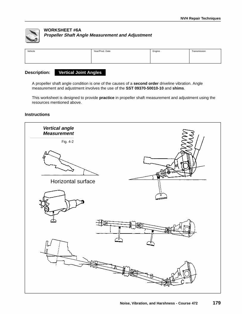
A propeller shaft angle condition is one of the causes of a second order driveline vibration. Anglemeasurement and adjustment involves the use of the SST 09370-50010-10 and shims .
This worksheet is designed to provide practice in propeller shaft measurement and adjustment using theresources mentioned above.
Instructions
Vertical angleMeasurement
Fig. 4-2
Horizontal surface
Vertical Joint Angles
Section 4
180 TOYOTA Technical Training
Measurement
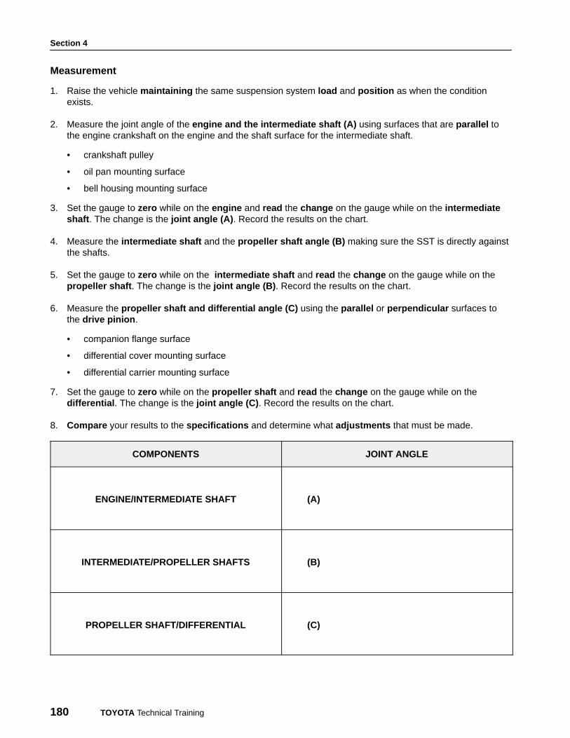
1. Raise the vehicle maintaining the same suspension system load and position as when the conditionexists.
2. Measure the joint angle of the engine and the intermediate shaft (A) using surfaces that are parallel tothe engine crankshaft on the engine and the shaft surface for the intermediate shaft.
• crankshaft pulley
• oil pan mounting surface
• bell housing mounting surface
3. Set the gauge to zero while on the engine and read the change on the gauge while on the intermediateshaft . The change is the joint angle (A) . Record the results on the chart.
4. Measure the intermediate shaft and the propeller shaft angle (B) making sure the SST is directly againstthe shafts.
5. Set the gauge to zero while on the intermediate shaft and read the change on the gauge while on thepropeller shaft . The change is the joint angle (B) . Record the results on the chart.
6. Measure the propeller shaft and differential angle (C) using the parallel or perpendicular surfaces tothe drive pinion .
• companion flange surface
• differential cover mounting surface
• differential carrier mounting surface
7. Set the gauge to zero while on the propeller shaft and read the change on the gauge while on thedifferential . The change is the joint angle (C) . Record the results on the chart.
8. Compare your results to the specifications and determine what adjustments that must be made.
COMPONENTS JOINT ANGLE
ENGINE/INTERMEDIATE SHAFT (A)
INTERMEDIATE/PROPELLER SHAFTS (B)
PROPELLER SHAFT/DIFFERENTIAL (C)
NVH Repair Techniques
Noise, Vibration, and Harshness - Course 472 181
Questions
1. What lift points did you choose to maintain the suspension height while raising the vehicle?
2. What are the increments between the degree marks on the scale?
3. How do you know if the angle is positive or negative?
4. Does it make a difference which component you measure first when using the angle gauge?
5. What are the specifications that are acceptable?
6. How do your results compare to the specifications?
Section 4
182 TOYOTA Technical Training
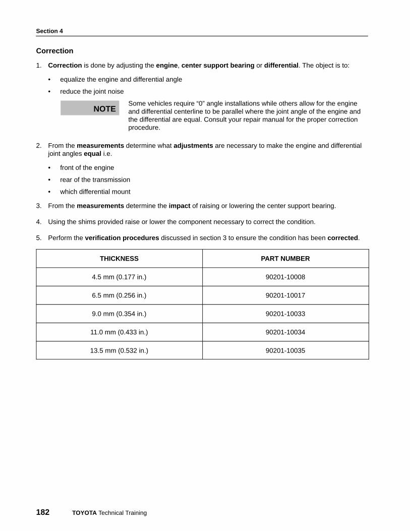
Correction
1. Correction is done by adjusting the engine , center support bearing or differential . The object is to:
• equalize the engine and differential angle
• reduce the joint noise
Some vehicles require “0” angle installations while others allow for the engineand differential centerline to be parallel where the joint angle of the engine andthe differential are equal. Consult your repair manual for the proper correctionprocedure.
2. From the measurements determine what adjustments are necessary to make the engine and differentialjoint angles equal i.e.
• front of the engine
• rear of the transmission
• which differential mount
3. From the measurements determine the impact of raising or lowering the center support bearing.
4. Using the shims provided raise or lower the component necessary to correct the condition.
5. Perform the verification procedures discussed in section 3 to ensure the condition has been corrected .
THICKNESS PART NUMBER
4.5 mm (0.177 in.) 90201-10008
6.5 mm (0.256 in.) 90201-10017
9.0 mm (0.354 in.) 90201-10033
11.0 mm (0.433 in.) 90201-10034
13.5 mm (0.532 in.) 90201-10035
NOTE

NVH Repair Techniques
Noise, Vibration, and Harshness - Course 472 183
Questions
1. What adjustments should be made to the following?
Engine mounts: Up or Down
Rear transmission mounts: Up or Down
Center carrier: Up of Down
Differential: Up or Down
2. What is the relationship between the thickness of the shim and the change in the joint angle? i.e. thousandthsvs. degrees.
3. What determines this relationship between shim thickness and angle in question #2?
4. Did the condition improve after the adjustment?
• differential cover mounting surface
• differential carrier mounting surface

Section 4
184 TOYOTA Technical Training

NVH Repair Techniques
Noise, Vibration, and Harshness - Course 472 185
WORKSHEET #6BPropeller Shaft Angle Measurement and Adjustment
Vehicle Year/Prod. Date Engine Transmission
Description:
Horizontal joint angles can have the same impact on vibration as the vertical joint angles but are moredifficult to measure. Due to the acceleration and deceleration of a joint as it rotates it is important to ensurethat the working angles cancel these changes in speed and provide a smooth output and no vibration.
The following sheet is designed to provide instruction and practice in measuring and correcting thesehorizontal joint angles.
Instruction
Horizontal PropellerShaft angle
Fig. 4-3
Horizontal Joint Angles

Section 4
186 TOYOTA Technical Training
Measurement Instructions
Engine
1. Raise the vehicle maintaining the same suspension system load and position as when the conditionexists.
2. Drop a plumb line from the crank pulley and place a strip of tape under the plumb points. Mark the plumbpoints A and B on the tape.
3. Determine the mid-point (1) between points A and B.
4. Drop a plumb line from the transmission extension housing and place a strip of tape under the plumbpoints. Mark the plumb points C and D on the tape.
5. Determine the mid-point (2) between points C and D.
Intermediate and Propeller Shafts
6. Use the same techniques outlined above to determine the mid-points of the ends of each shaft.
mid-point (3) of E and F
mid-point (4) of G and H
mid-point (5) of I and J
mid-point (6) of K and L
Differential
7. The same techniques are used to measure the companion flange and both axle housings :
mid-point (7) of M and N
mid-point (8) of P and Q
mid-point (9) of R and S
8. (10) is the perpendicular intersection of the center line formed with (8) - (9) and the pinion drive through (7).
9. Connect all center lines with thread .
10. Place a protractor on the thread at joint angle (A), (B) and (C) to measure the angles . Record yourreadings on the chart.

NVH Repair Techniques
Noise, Vibration, and Harshness - Course 472 187
COMPONENTS JOINT ANGLE
ENGINE/INTERMEDIATE SHAFT (A)
INTERMEDIATE/PROPELLER SHAFTS (B)
PROPELLER SHAFT/DIFFERENTIAL (C)
Correction Instructions
1. Adjust the engine center line (1 - 2) and/or differential center line (7 - 10) to make them parallel to eachother and joint angles (A) and (C) equal .
2. Adjust the center lines of the engine, intermediate shaft, propeller shaft, and differential to make them asstraight as possible and reduce joint angle (A) and (C).
3. Perform the verification procedures discussed in Section 3 to ensure the condition has been corrected .
Questions
1. List what could cause the horizontal angle to change.
Section 4
188 TOYOTA Technical Training
2. List the components and angle that would be effected.
3. What is the value of using a protractor in this worksheet?
4. What type of vibration would you read on the NVH Analyzer with a horizontal joint angle condition?
NVH Repair Techniques
Noise, Vibration, and Harshness - Course 472 189
WORKSHEET #7Tire Runout Measurement and Phase Matching
Repair Technique:
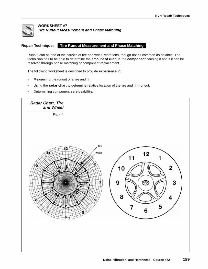
Runout can be one of the causes of tire and wheel vibrations, though not as common as balance. Thetechnician has to be able to determine the amount of runout , the component causing it and if it can beresolved through phase matching or component replacement.
The following worksheet is designed to provide experience in:
• Measuring the runout of a tire and rim.
• Using the radar chart to determine relative location of the tire and rim runout.
• Determining component serviceability .
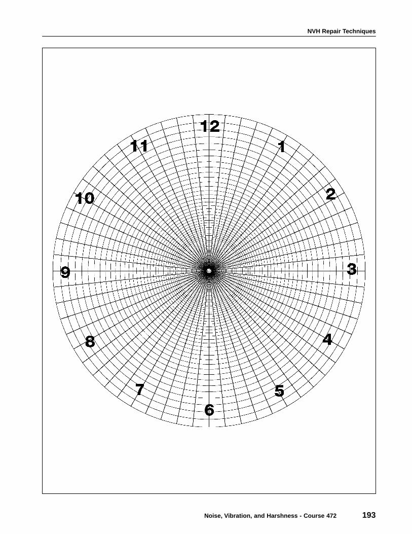
Radar Chart, Tireand Wheel
Fig. 4-4
Tire Runout Measurement and Phase Matching
Section 4
190 TOYOTA Technical Training
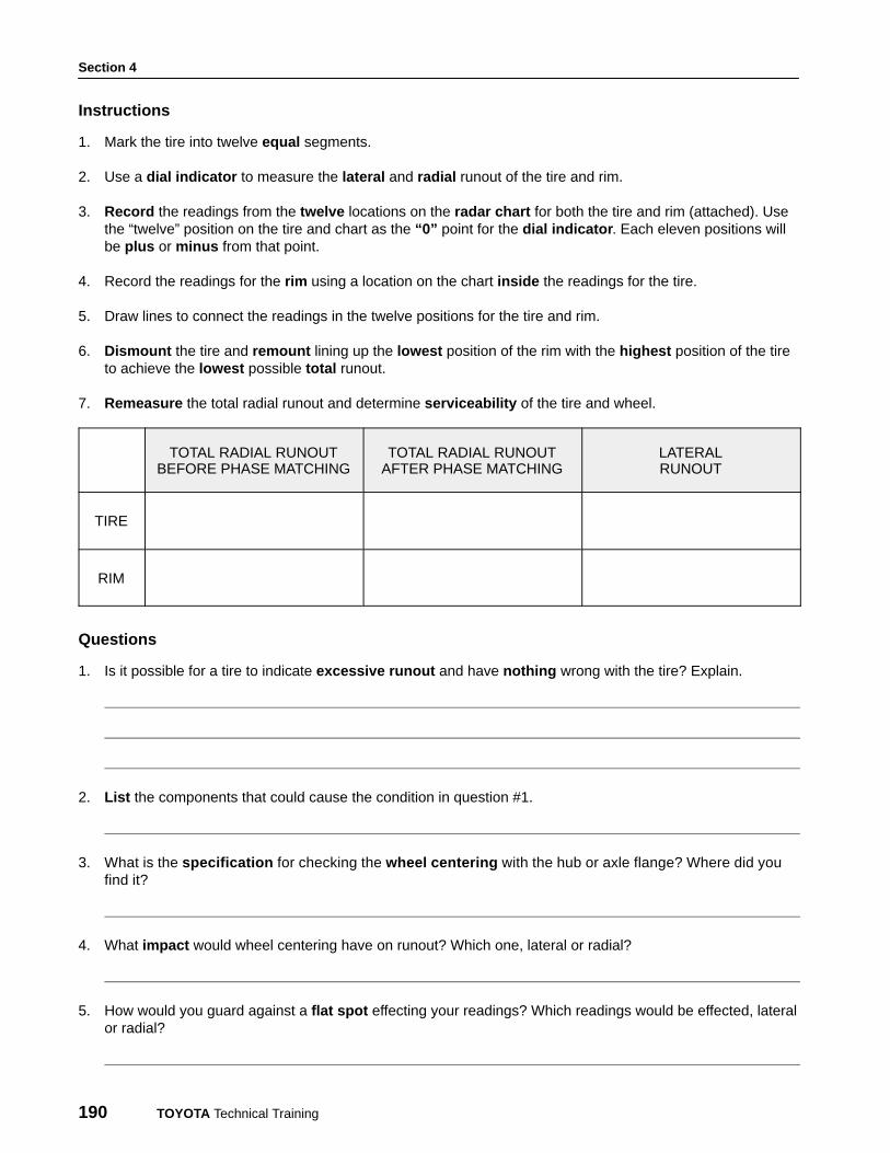
Instructions
1. Mark the tire into twelve equal segments.
2. Use a dial indicator to measure the lateral and radial runout of the tire and rim.
3. Record the readings from the twelve locations on the radar chart for both the tire and rim (attached). Usethe “twelve” position on the tire and chart as the “0” point for the dial indicator . Each eleven positions willbe plus or minus from that point.
4. Record the readings for the rim using a location on the chart inside the readings for the tire.
5. Draw lines to connect the readings in the twelve positions for the tire and rim.
6. Dismount the tire and remount lining up the lowest position of the rim with the highest position of the tireto achieve the lowest possible total runout.
7. Remeasure the total radial runout and determine serviceability of the tire and wheel.
TOTAL RADIAL RUNOUTBEFORE PHASE MATCHING
TOTAL RADIAL RUNOUTAFTER PHASE MATCHING
LATERALRUNOUT
TIRE
RIM
Questions
1. Is it possible for a tire to indicate excessive runout and have nothing wrong with the tire? Explain.
2. List the components that could cause the condition in question #1.
3. What is the specification for checking the wheel centering with the hub or axle flange? Where did youfind it?
4. What impact would wheel centering have on runout? Which one, lateral or radial?
5. How would you guard against a flat spot effecting your readings? Which readings would be effected, lateralor radial?
NVH Repair Techniques
Noise, Vibration, and Harshness - Course 472 191
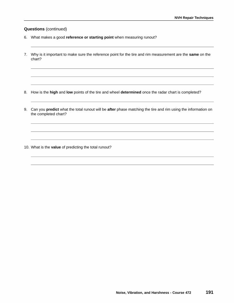
Questions (continued)
6. What makes a good reference or starting point when measuring runout?
7. Why is it important to make sure the reference point for the tire and rim measurement are the same on thechart?
8. How is the high and low points of the tire and wheel determined once the radar chart is completed?
9. Can you predict what the total runout will be after phase matching the tire and rim using the information onthe completed chart?
10. What is the value of predicting the total runout?

Section 4
192 TOYOTA Technical Training
NVH Repair Techniques
Noise, Vibration, and Harshness - Course 472 193

Section 4
194 TOYOTA Technical Training

NVH Repair Techniques
Noise, Vibration, and Harshness - Course 472 195
WORKSHEET #8Interior and Wind Noise
Interior and wind noise complaints are usually not as difficult to repair as they are to find . The difficulty infinding the source of a noise is caused by the many possible transmission paths of the noise. As a result,people sitting in different locations in the vehicle will have different opinions on the location of the noise.
Toyota has published two excellent programs to assist the technician with diagnosing and repair of theseconditions.
• Interior Noise P/N 00401-42856-R92
• Wind Noise P/N 00401-42968
This worksheet is designed to familiarize you with these programs and the skills required to successfullyresolve interior and wind noise complaints.
Interior and WindNoise Programs
Fig. 4-5

Section 4
196 TOYOTA Technical Training
Instructions
1. Review both the Interior and Wind Noise programs to become familiar with:
• The contents
• Diagnostic procedures
• Repair techniques
• The specification
• Service tips
• Check sheets
• Body fit standards
• Materials, tools and equipment
2. Use the diagnostic skills developed in this course, your experience in noise diagnosis and repair and theinformation above to answer the following questions.
Questions
1. What is the frequency range of wind noise?
2. What are the two conditions that effect wind noise?
3. At what speed does wind noise normally occur?
4. Why do the windows need to be shut ?
5. What are the two major vibrating forces of wind noise?
6. What should a visual inspection include for wind noise?
7. What are two important characteristics of the tape used to diagnose the wind noise?

NVH Repair Techniques
Noise, Vibration, and Harshness - Course 472 197
Questions (continued)
8. What are two values of the check sheets in the wind noise program?
9. What is the body fit standard for the gap between the top of the door and the roof line on a Paseo?
10. What is the advantage of having more than one person involved during the road test of a noise?
11. What is the part number for the kit available to repair noise complaints?
12. What is the value of the service tips section in the interior noise program?
Section 4
198 TOYOTA Technical Training
This section completes the information required to successfully
resolve most NVH complaints. You should have:
• A strong background in NVH principals and theory
• A diagnostic procedure including
− Verification of the customer complaint
− Classification of the symptom
− A road test procedure with the NVH Analyzer
• A pinpoint diagnosis procedure
• NVH repair techniques
Success in NVH service and repair will require practice honing the
skills developed in this course. Practice will provide the experience
necessary to quickly resolve NVH complaints the first time and ensure
long term customer satisfaction.
Summary