section 4.06 bituminous concrete 4.06.01 description 4.06
TRANSCRIPT

SECTION 4.06
BITUMINOUS CONCRETE 4.06.01—Description
4.06.02—Materials
4.06.03—Construction Methods
1. Material Documentation
2. Transportation of Mixture
3. Paving Equipment
4. Test Section
5. Transitions for Roadway Surface
6. Spreading and Finishing of Mixture
7. Longitudinal Joint Construction Methods
8. Contractor Quality Control (QC) Requirements
9. Temperature and Seasonal Requirements
10. Field Density
11. Acceptance Sampling and Testing
12. Density Dispute Resolution Process
13. Corrective Work Procedure
14. Protection of the Work
15. Cut Bituminous Concrete Pavement
4.06.04—Method of Measurement
4.06.05—Basis of Payment
4.06.01—Description: Work under this Section shall include the production, delivery, placement and
compaction of a uniform textured, non-segregated, smooth bituminous concrete pavement to the grade and
cross section shown on the plans.
The following terms as used in this specification are defined as:
Bituminous Concrete: A composite material consisting of prescribed amounts of asphalt binder and
aggregates. Asphalt binder may also contain additives engineered to modify specific properties and/or
behavior of the composite material. References to bituminous concrete apply to all of its forms, such as
those identified as hot-mix asphalt (HMA) or polymer-modified asphalt (PMA).
Bituminous Concrete Plant (Plant): A structure where aggregates and asphalt binder are combined in a
controlled fashion into a bituminous concrete mixture suitable for forming pavements and other paved
surfaces.
Course: A continuous layer (a lift or multiple lifts) of the same bituminous concrete mixture placed as
part of the pavement structure.
Density Lot: The total tonnage of all bituminous concrete placed in a single lift which are:
PWL density lots = When the project total estimated quantity per mixture is larger than 3,500 tons
Simple Average density lots = When the project total estimated quantity per mixture is 3,500 tons or
less
Disintegration: Erosion or fragmentation of the pavement surface which can be described as polishing,
weathering-oxidizing, scaling, spalling, raveling, or formation of potholes.
Dispute Resolution: A procedure used to resolve conflicts between the Engineer and the Contractor’s
results that may affect payment.
Hot Mix Asphalt (HMA): A bituminous concrete mixture typically produced at 325°F.
Job Mix Formula (JMF): A recommended aggregate gradation and asphalt binder content to achieve the
required mixture properties.
Lift: An application of a bituminous concrete mixture placed and compacted to a specified thickness in a
single paver pass.
Percent Within Limits (PWL): The percentage of the lot falling between the Upper Specification Limit
(USL) and the Lower Specification Limit (LSL).
Polymer Modified Asphalt (PMA): A bituminous concrete mixture containing a polymer-modified
asphalt binder and using a qualified warm mix technology.
Production Lot: The total tonnage of a bituminous concrete mixture from a single source that may
receive an adjustment.
Production Sub Lot: Portion of the production lot typically represented by a single sample.
Attachment 1

Quality Assurance (QA): All those planned and systematic actions necessary to provide CTDOT the
confidence that a Contractor will perform the work as specified in the Contract.
Quality Control (QC): The sum total of activities performed by the vendor (Producer, Manufacturer, and
Contractor) to ensure that a product meets contract specification requirements.
Superpave: A bituminous concrete mix design used in mixtures designated as “S*” Where “S” indicates
Superpave and * indicates the sieve related to the nominal maximum aggregate size of the mix.
Segregation: A non-uniform distribution of a bituminous concrete mixture in terms of gradation,
temperature, or volumetric properties.
Warm Mix Asphalt (WMA) Technology: A qualified additive or technology that may be used to
produce a bituminous concrete at reduced temperatures and/or increase workability of the mixture.
4.06.02—Materials: All materials shall meet the requirements of Section M.04.
1. Materials Supply: The bituminous concrete mixture must be from one source of supply and
originate from one Plant unless authorized by the Engineer.
2. Recycled Materials: Reclaimed Asphalt Pavement (RAP), Crushed Recycled Container Glass
(CRCG), Recycled Asphalt Shingles (RAS), or crumb rubber (CR) from recycled tires may be incorporated
in bituminous concrete mixtures in accordance with Project Specifications.
4.06.03—Construction Methods 1. Material Documentation: All vendors producing bituminous concrete must have Plants with
automated vehicle-weighing scales, storage scales, and material feeds capable of producing a delivery
ticket containing the information below.
a. State of Connecticut printed on ticket.
b. Name of Producer, identification of Plant, and specific storage silo if used.
c. Date and time.
d. Mixture Designation, mix type and level. Curb mixtures for machine-placed curbing must state "curb
mix only."
e. If WMA Technology is used, “-W”must be listed following the mixture designation.
f. Net weight of mixture loaded into the vehicle. (When RAP and/or RAS is used, the moisture content
shall be excluded from mixture net weight.)
g. Gross weight (equal to the net weight plus the tare weight or the loaded scale weight).
h. Tare weight of vehicle (daily scale weight of the empty vehicle).
i. Project number, purchase order number, name of Contractor (if Contractor other than Producer).
j. Vehicle number - unique means of identification of vehicle.
k. For Batch Plants: individual aggregate, recycled materials, and virgin asphalt max/target/min weights
when silos are not used.
l. For every mixture designation: the running daily and project total delivered and sequential load
number.
The net weight of mixture loaded into the vehicle must be equal to the cumulative measured weights of its
components.
The Contractor must notify the Engineer immediately if, during production, there is a malfunction of the
weight recording system in the automated Plant. Manually written tickets containing all required
information will be allowed for no more than 1 hour.
The State reserves the right to have an Inspector present to monitor batching and/or weighing operations.
2. Transportation of Mixture: The mixture shall be transported in vehicles that are clean of all foreign
material, excessive coating or cleaning agents, and that have no gaps through which material might spill.
Any material spilled during the loading or transportation process shall be quantified by re-weighing the
vehicle. The Contractor shall load vehicles uniformly so that segregation is minimized. Loaded vehicles
shall be tightly covered with waterproof covers acceptable to the Engineer. Mesh covers are prohibited.
The cover must minimize air infiltration. Vehicles found not to be in conformance shall not be loaded
Vehicles with loads of bituminous concrete being delivered to State projects must not exceed the statutory
or permitted load limits referred to as gross vehicle weight (GVW). The Contractor shall furnish a list and
allowable weights of all vehicles transporting mixture. The State reserves the right to check the gross and
tare weight of any vehicle. If the gross or tare weight varies from that shown on the delivery ticket by more
than 0.4%, the Engineer will recalculate the net weight. The Contractor shall correct the discrepancy to the
Attachment 1

satisfaction of the Engineer.
If a vehicle delivers mixture to the Project and the delivery ticket indicates that the vehicle is overweight,
the load may not be rejected but a “Measured Weight Adjustment” will be taken in accordance with Article
4.06.04.
Vehicle body coating and cleaning agents must not have a deleterious effect on the mixture. The use of
solvents or fuel oil, in any concentration, is prohibited for the coating of vehicle bodies.
For each delivery, the Engineer shall be provided a clear, legible copy of the delivery ticket.
3. Paving Equipment: The Contractor shall have the necessary paving and compaction equipment at the
Project Site to perform the work. All equipment shall be in good working order and any equipment that is
worn, defective, or inadequate for performance of the work shall be repaired or replaced by the Contractor
to the satisfaction of the Engineer. During the paving operation, the use of solvents or fuel oil, in any
concentration, is strictly prohibited as a release agent or cleaner on any paving equipment (i.e., rollers,
pavers, transfer devices, etc.).
Refueling or cleaning of equipment is prohibited in any location on the Project where fuel or solvents
might come in contact with paved areas or areas to be paved. Solvents used in cleaning mechanical
equipment or hand tools shall be stored clear of areas paved or to be paved. Before any such equipment
and tools are cleaned, they shall be moved off of areas paved or to be paved.
Pavers: Each paver shall have a receiving hopper with sufficient capacity to provide for a uniform
spreading operation and a distribution system that places the mix uniformly, without segregation. The
paver shall be equipped with and use a vibratory screed system with heaters or burners. The screed system
shall be capable of producing a finished surface of the required evenness and texture without tearing,
shoving, or gouging the mixture. Pavers with extendible screed units as part of the system shall have auger
extensions and tunnel extenders as necessary. Automatic screed controls for grade and slope shall be used
at all times unless otherwise authorized by the Engineer. The controls shall automatically adjust the screed
to compensate for irregularities in the preceding course or existing base. The controls shall maintain the
proper transverse slope and be readily adjustable, and shall operate from a fixed or moving reference such
as a grade wire or floating beam.
Rollers: All rollers shall be self-propelled and designed for compaction of bituminous concrete. Roller
types shall include steel wheeled, pneumatic, or a combination thereof. Rollers that operate in a dynamic
mode shall have drums that use a vibratory or oscillatory system or combination. Vibratory rollers shall be
equipped with indicators for amplitude, frequency, and speed settings/readouts to measure the impacts per
foot during the compaction process. Oscillatory rollers shall be equipped with frequency indicators.
Rollers can operate in the dynamic mode using the oscillatory system on concrete structures such as bridges
and catch basins if at the lowest frequency setting.
Pneumatic tire rollers shall be equipped with wide-tread compaction tires capable of exerting an average
contact pressure from 60 to 90 psi uniformly over the surface. The Contractor shall furnish documentation
to the Engineer regarding tire size, pressure and loading to confirm that the proper contact pressure is being
developed and that the loading and contact pressure are uniform for all wheels.
Lighting: For paving operations which will be performed during hours of darkness the paving equipment
shall be equipped with lighting fixtures as described below or with an approved equal. Lighting shall
minimize glare to passing traffic. The lighting options and minimum number of fixtures are listed in
Tables 4.06-1 and 4.06-2.
TABLE 4.06-1: Minimum Paver lighting
Option Fixture Configuration Fixture Quantity Requirement
1
Type A 3 Mount over screed area
Type B (narrow) or Type C (spot) 2 Aim to auger and guideline
Type B (wide)or Type C (flood) 2 Aim 25feet behind paving machine
2 Type D Balloon 2 Mount over screed area
Attachment 1
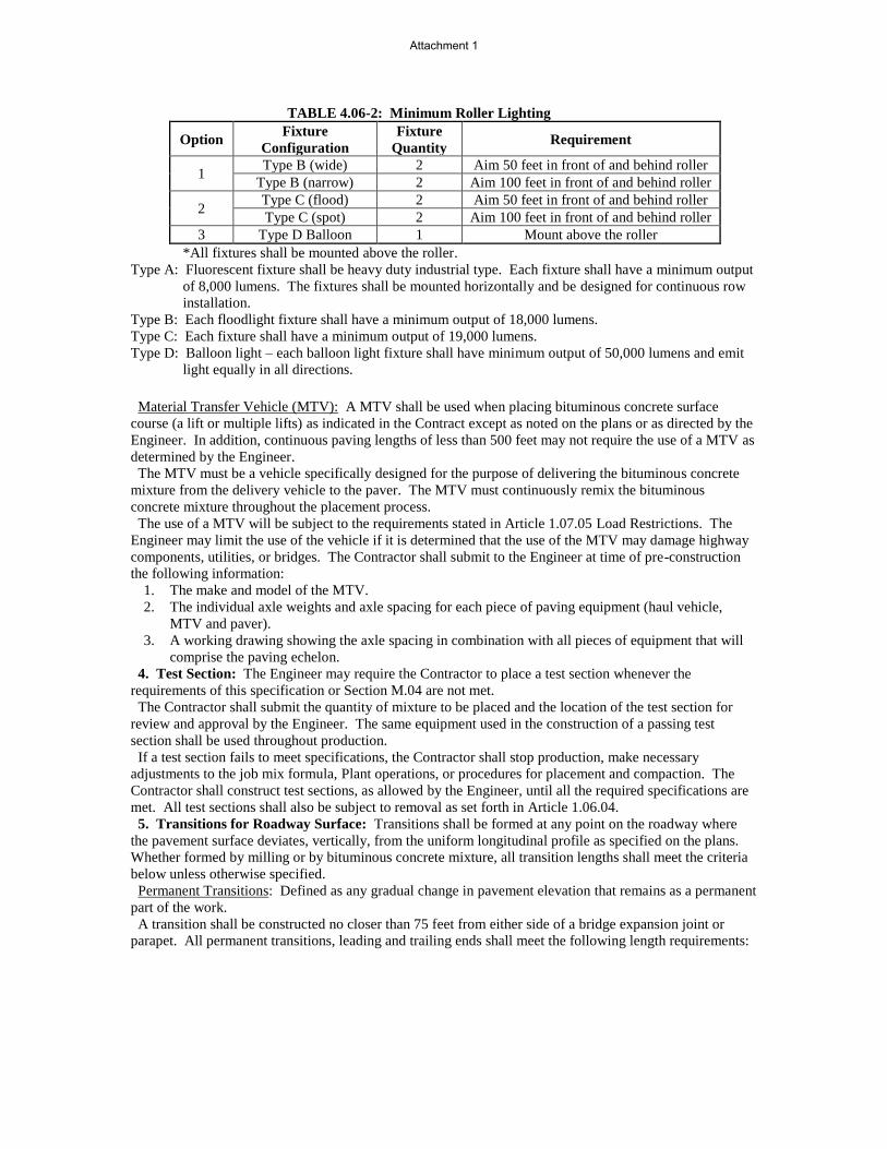
TABLE 4.06-2: Minimum Roller Lighting
Option Fixture
Configuration
Fixture
Quantity Requirement
1 Type B (wide) 2 Aim 50 feet in front of and behind roller
Type B (narrow) 2 Aim 100 feet in front of and behind roller
2 Type C (flood) 2 Aim 50 feet in front of and behind roller
Type C (spot) 2 Aim 100 feet in front of and behind roller
3 Type D Balloon 1 Mount above the roller
*All fixtures shall be mounted above the roller.
Type A: Fluorescent fixture shall be heavy duty industrial type. Each fixture shall have a minimum output
of 8,000 lumens. The fixtures shall be mounted horizontally and be designed for continuous row
installation.
Type B: Each floodlight fixture shall have a minimum output of 18,000 lumens.
Type C: Each fixture shall have a minimum output of 19,000 lumens.
Type D: Balloon light – each balloon light fixture shall have minimum output of 50,000 lumens and emit
light equally in all directions.
Material Transfer Vehicle (MTV): A MTV shall be used when placing bituminous concrete surface
course (a lift or multiple lifts) as indicated in the Contract except as noted on the plans or as directed by the
Engineer. In addition, continuous paving lengths of less than 500 feet may not require the use of a MTV as
determined by the Engineer.
The MTV must be a vehicle specifically designed for the purpose of delivering the bituminous concrete
mixture from the delivery vehicle to the paver. The MTV must continuously remix the bituminous
concrete mixture throughout the placement process.
The use of a MTV will be subject to the requirements stated in Article 1.07.05 Load Restrictions. The
Engineer may limit the use of the vehicle if it is determined that the use of the MTV may damage highway
components, utilities, or bridges. The Contractor shall submit to the Engineer at time of pre-construction
the following information:
1. The make and model of the MTV.
2. The individual axle weights and axle spacing for each piece of paving equipment (haul vehicle,
MTV and paver).
3. A working drawing showing the axle spacing in combination with all pieces of equipment that will
comprise the paving echelon.
4. Test Section: The Engineer may require the Contractor to place a test section whenever the
requirements of this specification or Section M.04 are not met.
The Contractor shall submit the quantity of mixture to be placed and the location of the test section for
review and approval by the Engineer. The same equipment used in the construction of a passing test
section shall be used throughout production.
If a test section fails to meet specifications, the Contractor shall stop production, make necessary
adjustments to the job mix formula, Plant operations, or procedures for placement and compaction. The
Contractor shall construct test sections, as allowed by the Engineer, until all the required specifications are
met. All test sections shall also be subject to removal as set forth in Article 1.06.04.
5. Transitions for Roadway Surface: Transitions shall be formed at any point on the roadway where
the pavement surface deviates, vertically, from the uniform longitudinal profile as specified on the plans.
Whether formed by milling or by bituminous concrete mixture, all transition lengths shall meet the criteria
below unless otherwise specified.
Permanent Transitions: Defined as any gradual change in pavement elevation that remains as a permanent
part of the work.
A transition shall be constructed no closer than 75 feet from either side of a bridge expansion joint or
parapet. All permanent transitions, leading and trailing ends shall meet the following length requirements:
Attachment 1

Posted Speed Limit Permanent Transition Length Required
> 35 mph 30 feet per inch of elevation change
35 mph or less 15 feet per inch of elevation change
In areas where it is impractical to use the above-described permanent transition lengths, the use of a
shorter permanent transition length may be permitted when approved by the Engineer.
Temporary Transitions: Defined as a transition that does not remain a permanent part of the work.
All temporary transitions shall meet the following length requirements:
Posted Speed
Limit Temporary Transition Length Required
> 50 mph Leading Transition: 15 feet per inch of vertical change (thickness)
Trailing Transition: 6 feet per inch of vertical change (thickness)
40, 45 or 50
mph Leading and Trailing: 4 feet per inch of vertical change (thickness)
35 mph or less Leading and Trailing: 3 feet per inch of vertical change (thickness)
Note: Any temporary transition to be in place over the winter shutdown period or during extended
periods of inactivity (more than 14 calendar days) shall meet the greater than 50 mph requirements shown
above.
6. Spreading and Finishing of Mixture: Prior to the placement of the mixture, the underlying base
course shall be brought to the plan grade and cross section within the allowable tolerance.
Immediately before placing a bituminous concrete lift, a uniform coating of tack coat shall be applied to
all existing underlying pavement surfaces and on the exposed surface of a wedge joint. Such surfaces shall
be clean and dry. Sweeping or other means acceptable to the Engineer shall be used.
The mixture shall not be placed whenever the surface is wet or frozen.
Tack Coat Application: The tack coat shall be applied by a pressurized spray system that results in
uniform overlapping coverage at an application rate of 0.03 to 0.05 gal./s.y. for a non-milled surface and an
application rate of 0.05 to 0.07 gal./s.y. for a milled surface. For areas where both milled and un-milled
surfaces occur, the tack coat shall be an application rate of 0.03 to 0.05 gal /s.y. The Engineer must
approve the equipment and the method of measurement prior to use. The material for tack coat shall be
heated to 160°F ± 10°F and shall not be further diluted.
Tack coat shall be allowed sufficient time to break prior to any paving equipment or haul vehicles driving
on it.
The Contractor may request to omit the tack coat application between bituminous concrete layers that
have not been exposed to traffic and are placed during the same work shift. Requests to omit tack coat
application on the upper and lower surfaces of a wedge joint will not be considered.
Placement: The mixture shall be placed and compacted to provide a smooth, dense surface with a uniform
texture and no segregation at the specified thickness and dimensions indicated in the plans and
specifications.
When unforeseen weather conditions prevent further placement of the mixture, the Engineer is
not obligated to accept or place the bituminous concrete mixture that is in transit from the Plant.
In advance of paving, traffic control requirements shall be set up, maintained throughout placement, and
shall not be removed until all associated work including density testing is completed.
The mixture temperature will be verified by means of a probe or infrared type of thermometer. The
placement temperature range shall be listed in the quality control plan (QCP) for placement and meet the
requirements of Table M.04.03-4. Any HMA material that that falls outside the specified temperature
range as measured by a probe thermometer may be rejected.
Attachment 1

The Contractor shall inspect the newly placed pavement for defects in mixture or placement before rolling
is started. Any deviation from standard crown or section shall be immediately remedied by placing
additional mixture or removing surplus mixture. Such defects shall be corrected to the satisfaction of the
Engineer.
Where it is impracticable due to physical limitations to operate the paving equipment, the Engineer may
permit the use of other methods or equipment. Where hand spreading is permitted, the mixture shall be
placed by means of suitable shovels and other tools, and in a uniformly loose layer at a thickness that will
result in a completed pavement meeting the designed grade and elevation.
Placement Tolerances: Each lift of bituminous concrete placed at a specified thickness shall meet the
following requirements for thickness and area. Any pavement exceeding these limits shall be subject to an
adjustment or removal. Lift tolerances will not relieve the Contractor from meeting the final designed
grade. Lifts of specified non-uniform thickness, i.e. wedge or shim course, shall not be subject to thickness
and area adjustments.
a) Thickness: Where the average thickness of the lift exceeds that shown on the plans beyond the
tolerances shown in Table 4.06-3, the Engineer will calculate the thickness adjustment in accordance
with Article 4.06.04.
TABLE 4.06-3: Thickness Tolerances
Mixture Designation Lift Tolerance
S1 +/- 3/8 inch
S0.25, S0.375, S0.5 +/- 1/4 inch
Where the thickness of the lift of mixture is less than that shown on the plans beyond the tolerances
shown in Table 4.06-3, the Contractor, with the approval of the Engineer, shall take corrective action
in accordance with this Section.
b) Area: Where the width of the lift exceeds that shown on the plans by more than the specified
thickness, the Engineer will calculate the area adjustment in Article 4.06.04.
c) Delivered Weight of Mixture: When the delivery ticket shows that the truck exceeds the allowable
gross weight for the vehicle type, the Engineer will calculate the weight adjustment in accordance
with Article 4.06.04.
Transverse Joints: All transverse joints shall be formed by saw-cutting to expose the full thickness of the
lift. Tack coat shall be applied to the sawn face immediately prior to additional mixture being placed.
Compaction: The Contractor shall compact the mixture to meet the density requirements as stated in
Article 4.06.04 and eliminate all roller marks without displacement, shoving cracking, or aggregate
breakage.
When placing a lift with a specified thickness less than 1 1/2 inches, or a wedge course, the Contractor
shall provide a minimum rolling pattern as determined by the development of a compaction curve. The
procedure to be used shall be documented in the Contractor’s QCP for placement and demonstrated on the
first day of placement.
The use of the vibratory system on concrete structures is prohibited. When approved by the Engineer, the
Contractor may operate a roller using an oscillatory system at the lowest frequency setting.
If the Engineer determines that the use of compaction equipment in the dynamic mode may damage
highway components, utilities or adjacent property, the Contractor shall provide alternate compaction
equipment.
Rollers operating in the dynamic mode shall be shut off when changing directions.
These allowances will not relieve the Contractor from meeting pavement compaction requirements.
Surface Requirements:
Each lift of the surface course shall not vary more than 1/4 inch from a Contractor-supplied 10 foot
straightedge. For all other lifts of bituminous concrete, the tolerance shall be 3/8 inch. Such
tolerance will apply to all paved areas.
Any surface that exceeds these tolerances shall be corrected by the Contractor at its own expense.
7. Longitudinal Joint Construction Methods: The Contractor shall use Method I - Notched Wedge
Joint (see Figure 4.06-1) when constructing longitudinal joints where lift thicknesses are 1 ½ inches to 3
inches. S1.0 mixtures shall be excluded from using Method I. Method II - Butt Joint (see Figure 4.06-2)
shall be used for lifts less than 1 1/2 inches or greater than 3 inches. Each longitudinal joint shall maintain
a consistent offset from the centerline of the roadway along its entire length. The difference in elevation
Attachment 1

between the two faces of any completed longitudinal joint shall not exceed 1/4 inch at any location.
Method I - Notched Wedge Joint:
A notched wedge joint shall be constructed as shown in Figure 4.06-1 using a device that is attached to the
paver screed and is capable of independently adjusting the top and bottom vertical notches. The device
shall have an integrated vibratory system. The top vertical notch must be located at the centerline or lane
line in the final lift. The requirement for paving full width “curb to curb” as described in Method II may be
waived if addressed in the QC plan and approved by the Engineer.
The taper portion of the wedge joint shall be evenly compacted using equipment other than the paver or
notch wedge joint device. The compaction device shall be the same width as the taper and not reduce the
angle of the wedge or ravel the top notch of the joint during compaction.
When placed on paved surfaces, the area below the sloped section of the joint shall be treated with tack
coat. The top surface of the sloped section of the joint shall be treated with tack coat prior to placing the
completing pass.
The taper portion of the wedge joint shall not be exposed to traffic for more than 5 calendar days.
Figure 4.06-1: Notched Wedge Joint (Not to Scale)
Any exposed wedge joint must be located to allow for the free draining of water from the road surface.
The Engineer reserves the right to define the paving limits when using a wedge joint that will be exposed
to traffic.
If Method I cannot be used on those lifts which are 1 ½ inches to 3 inches, Method III may be substituted
according to the requirements below for “Method III - Butt Joint with Hot Poured Rubberized Asphalt
Treatment.”
Method II - Butt Joint:
When adjoining passes are placed, the Contractor shall use the end gate to create a near vertical edge
(refer to Figure 4.06-2). The completing pass (hot side) shall have sufficient mixture so that the compacted
thickness is not less than the previous pass (cold side). During placement of multiple lifts, the longitudinal
joint shall be constructed in such a manner that it is located at least 6 inch from the joint in the lift
immediately below. The joint in the final lift shall be at the centerline or at lane lines. The end gate on the
paver should be set so there is an overlap onto the cold side of the joint.
The Contractor shall not allow any butt joint to be incomplete at the end of a work shift unless otherwise
allowed by the Engineer. When using this method, the Contractor is not allowed to leave a vertical edge
exposed at the end of a work shift and must complete paving of the roadway full width “curb to curb.”
Hot
side
Cold
Side
12” Taper
Top
Vertical Notch
1/2 - 3/4” Tack coat
Bottom
Vertical Notch
1/4” - 1/2”
Lift Thickness
1 1/2” - 3”
Varies
Attachment 1

Figure 4.06-2: Butt Joint (Not to Scale)
Method III - Butt Joint with Hot Poured Rubberized Asphalt Treatment:
If Method I cannot be used due to physical constraints in certain limited locations, the Contractor may
submit a request in writing for approval by the Engineer to use Method III as a substitution in those
locations. There shall be no additional measurement or payment made when Method III is substituted for
Method I. When required by the Contract or approved by the Engineer, Method III (see Figure 4.06-3)
shall be used.
Figure 4.06-3: Butt Joint with Hot Poured Rubberized Asphalt Treatment
(Not to Scale)
All of the requirements of Method II must be met with Method III. In addition, the longitudinal vertical
edge must be treated with a rubberized joint seal material meeting the requirements of ASTM D6690, Type
2. The joint sealant shall be placed on the face of the “cold side” of the butt joint as shown above prior to
placing the “hot side” of the butt joint. The joint seal material shall be applied in accordance with the
manufacturer’s recommendation so as to provide a uniform coverage and avoid excess bleeding onto the
newly placed pavement.
8. Contractor Quality Control (QC) Requirements: The Contractor shall be responsible for
maintaining adequate quality control procedures throughout the production and placement operations.
Therefore, the Contractor must ensure that the materials, mixture, and work provided by Subcontractors,
Suppliers, and Producers also meet Contract specification requirements.
This effort must be documented in Quality Control Plans (QCP) and must address the actions, inspection,
or sampling and testing necessary to keep the production and placement operations in control, to determine
when an operation has gone out of control and to respond to correct the situation in a timely fashion.
The Standard QCP for production shall consist of the quality control program specific to the production
facility.
There are 3 components to the QCP for placement: a Standard QCP, a Project Summary Sheet that details
Project-specific information, and, if applicable, a separate Extended Season Paving Plan as required in
4.06.03-9 “Temperature and Seasonal Requirements.”
The Standard QCP for both production and placement shall be submitted to the Department for approval
each calendar year and at a minimum of 30 days prior to production or placement.
Production or placement shall not occur until all QCP components have been approved by the Engineer.
Each QCP shall include the name and qualifications of a Quality Control Manager (QCM). The QCM
shall be responsible for the administration of the QCP, and any modifications that may become necessary.
The QCM shall have the ability to direct all Contractor personnel on the Project during paving operations.
The QCPs shall also include the name and qualifications of any outside testing laboratory performing any
Hot side Cold Side
Joint
Hot side Cold Side
Hot poured rubberized asphalt
treatment
Lift Thicknesses
Less than 1 1/2”
Greater than or
equal to 3”
Attachment 1

QC functions on behalf of the Contractor. The QC Technician performing in-place density testing shall be
NETTCP certified as a paving inspector.
Approval of the QCP does not relieve the Contractor of its responsibility to comply with the Project
specifications. The Contractor may modify the QCPs as work progresses and must document the changes
in writing prior to resuming operations. These changes include but are not limited to changes in quality
control procedures or personnel. The Department reserves the right to deny significant changes to the
QCPs.
QCP for Production: Refer to M.04.03-1.
QCP for Placement: The Standard QCP, Project Summary Sheet, and Extended Season Paving Plan shall
conform to the format provided by the Engineer. The format is available at
http://www.ct.gov/dot/lib/dot/documents/dconstruction/pat/qcp_outline_hma_placement.pdf
The Contractor shall perform all quality control sampling and testing, provide inspection, and exercise
management control to ensure that bituminous concrete placement conforms to the requirements as outlined
in its QCP during all phases of the work. The Contractor shall document these activities for each day of
placement.
The Contractor shall submit complete field density testing and inspection records to the Engineer within
48 hours in a manner acceptable to the Engineer.
The Contractor may obtain 1 mat core and 1 joint core per day for process control, provided this process is
detailed in the QCP. The results of these process control cores shall not be used to dispute the
Department’s determinations from the acceptance cores. The Contractor shall submit the location of each
process control core to the Engineer for approval prior to taking the core. The core holes shall be filled to
the same requirements described in Subarticle 4.06.03-10.
9. Temperature and Seasonal Requirements: Paving, including placement of temporary pavements,
shall be divided into 2 seasons, “In-Season” and “Extended-Season.” In-Season paving occurs from May 1
to October 14, and Extended Season paving occurs from October 15 to April 30. The following
requirements shall apply unless otherwise authorized or directed by the Engineer:
Mixtures shall not be placed when the air or subbase temperature is less than 40°F regardless of
the season.
Should paving operations be scheduled during the Extended Season, the Contractor must submit
an Extended Season Paving Plan for the Project that addresses minimum delivered mix
temperature considering WMA, PMA, or other additives; maximum paver speed; enhanced rolling
patterns; and the method to balance mixture delivery and placement operations. Paving during
Extended Season shall not commence until the Engineer has approved the plan.
10. Field Density The Contractor shall obtain cores for the determination of mat and longitudinal joint
density of bituminous concrete pavements. Within five calendar days of placement, mat and joint cores
shall be extracted on each lift with a specified thickness of 1 1/2 inches or more. Joint cores shall not be
extracted on HMA S1.0 lifts.
The Contractor shall extract cores from random locations determined by the Engineer in accordance with
ASTM D3665. Four (4) or six (6) inch diameter cores shall be extracted for S0.25, S0.375 and S0.5
mixtures; 6 inch diameter cores shall be required for S1.0 mixtures. The Contractor shall coordinate with
the Engineer to witness the extraction, labeling of cores, and filling of the core holes.
Each lift will be separated into lots as follows:
a. Simple Average Density Lots: For total estimated quantities below 2,000 tons, the lift will be
evaluated in one lot which will include the total paved tonnage of the lift and all longitudinal joints
between the curb lines.
For total estimated quantities between 2,000 and 3,500 tons, the lift will be evaluated in two lots in
which each lot will include approximately half of the total tonnage placed for the full paving width
of a lift including all longitudinal joints between the curb lines.
b. PWL Density Lots: Mat density lots will include each 3,500 tons of mixture placed within 30
calendar days. Joint density lots will include 14,000 linear feet of constructed joints. Bridge
density lots will always be analyzed using simple average lot methodology.
c. Partial Density Lot (For PWL only): A mat density lot with less than 3,500 tons or a joint density
lot with less than 14,000 linear feet due to:
- completion of the course; or
- a lot spanning 30 calendar days.
Prior to paving, the type and number of lot(s) will be determined by the Engineer. Noncontiguous areas
Attachment 1

such as highway ramps may be combined to create one lot.
After the lift has been compacted and cooled, the Contractor shall cut cores to a depth equal to or greater
than the lift thickness and shall remove them without damaging the lift(s) to be tested. Any core that is
damaged or obviously defective while being obtained will be replaced with a new core from a location
within 2 feet measured in a longitudinal direction.
A mat core shall not be located any closer than 1 foot from the edge of a paver pass. If a random number
locates a core less than 1 foot from any edge, the location will be adjusted by the Engineer so that the outer
edge of the core is 1 foot from the edge of the paver pass.
Method I, Notched Wedge Joint cores shall be taken so that the center of the core is 5 inches from the
visible joint on the hot mat side (Figure 4.06-4).
Figure 4.06-4: Notched Wedge Joint Cores (Not to Scale)
When Method II or Method III Butt Joint is used, cores shall be taken from the hot side so the edge of the
core is within 1 inch of the longitudinal joint.
The cores shall be labeled by the Contractor with the Project number, date placed, lot number, and sub-lot
number. The core’s label shall include “M” for a mat core and “J” for a joint core. For example, a mat
core from the first lot and the first sub-lot shall be labeled with “M1 – 1.” A mat core from the second lot
and first sub-lot shall be labeled “M2-1” (see Figure 4.06-5). The Engineer shall fill out a MAT-109 to
accompany the cores. The Contractor shall deliver the cores and MAT-109 to the Department’s Central
Lab. The Contractor shall use a container approved by the Engineer. The container shall have a lid capable
of being locked shut and tamper proof. The Contractor shall use foam, bubble wrap, or another suitable
material to prevent the cores from being damaged during handling and transportation. Once the cores and
MAT-109 are in the container the Engineer will secure the lid using security seals at the removable
hinges(s) and at the lid opening(s). The security seals’ identification number must be documented on the
MAT-109. All sealed containers shall be delivered to the Department’s Central Lab within two working
days from time of extraction. Central Lab personnel will break the security seal and take possession of the
cores.
Figure 4.06-5: Labeling of Cores
Project #
(M or J) Lot - Sub lot
85-219
M2 - 1
07/26/16 Date Placed
Attachment 1

Each core hole shall be filled within 4 hours upon core extraction. Prior to being filled, the hole shall be
prepared by removing any free water and applying tack coat using a brush or other means to uniformly
cover the cut surface. The core hole shall be filled using a bituminous concrete mixture at a minimum
temperature of 240°F containing the same or smaller nominal maximum aggregate size and compacted with
a hand compactor or other mechanical means to the maximum compaction possible. The bituminous
concrete shall be compacted to 1/8 inch above the finished pavement.
Simple Average Density Lots:
A standard simple average density lot is the quantity of material placed within the defined area excluding
any bridge decks.
A combo simple average density lot is the quantity of material placed within the defined area including
bridge decks less than or equal to 500 feet long.
A bridge simple average density lot is the quantity of material placed on a bridge deck longer than 500
feet.
The number of cores per lot shall be determined in accordance with Table 4.06-4. If a randomly selected
mat or joint core location is on a bridge deck, the core is to be obtained on the bridge deck in addition to the
core(s) required on the bridge deck.
The number of cores per lot shall be determined in accordance with Table 4.06-5. Multiple bridge decks
can be combined into one lot if the paving and underlying conditions are comparable. If multiple bridge
decks are combined into a single bridge lot, at least one mat and joint core shall be obtained on each bridge.
The longitudinal locations of mat cores within a standard, combo, or bridge lot containing multiple paving
passes will be determined using the combined length of the paving passes within the lot.
TABLE 4.06-4: Number of Cores per Lot (Simple Average)
Lot Type No. of Mat Cores No. of Joint Cores
Standard Lot < 500 Tons 3 3
Standard Lot ≥ 500 Tons 4 4
Combo Lot < 500 Tons 2 plus
1 per bridge
(< 300’)
2 per bridge
(301’ – 500’)
2 plus 1 per bridge
(< 300)
2 per bridge
(301’ – 500’) Combo Lot ≥ 500 Tons(1) 4 plus 4 plus
TABLE 4.06-5: Number of Core per Bridge Density Lot (Simple Average)
Length of Bridge(s)
(Feet) Minimum No. of Mat Cores Minimum No. of Joint Cores
< 500 2 2
501 – 1,500 3 3
1,501 – 2,500 4 4
2,501 and greater 5 5
PWL Density Lots:
A PWL mat density lot is 3,500 tons of material placed within the defined area excluding any bridges.
One mat core will be obtained per every 500 tons placed.
A PWL joint density lot is 14,000 linear feet of longitudinal joint excluding any joints on bridge decks.
One joint core will be obtained per every 2,000 linear feet of joint.
Bridge density lots will always be analyzed as using the simple average lot methodology. The number of
cores per lot shall be determined in accordance with Table 4.06-5. Multiple bridge decks can be combined
into one lot if the paving and underlying conditions are comparable. If multiple bridge decks are combined
into a single bridge lot, at least one mat and joint core shall be obtained on each bridge.
11. Acceptance Sampling and Testing: Sampling shall be performed in accordance with ASTM
D3665 or a statistically-based procedure of stratified random sampling approved by the Engineer.
Plant Material Acceptance: The Contractor shall provide the required sampling and testing during all
Attachment 1

phases of the work in accordance with M.04. The Department will verify the Contractor’s acceptance test
results. Should any test results exceed the specified tolerances in the Department’s current QA Program for
Materials, the Contractor’s test results for a subject lot or sub lot may be replaced with the Department’s
results for the purpose of calculating adjustments. The verification procedure is included in the
Department’s current QA Program for Materials.
Density Acceptance: The Engineer will perform all acceptance testing in accordance with AASHTO T
331. The density of each core will be determined using the daily production’s average maximum
theoretical specific gravity (Gmm) established during the testing of the parent material at the Plant. When
there was no testing of the parent material or any Gmm exceeds the specified tolerances in the
Department’s current QA Program for Materials, the Engineer will determine the maximum theoretical
density value to be used for density calculations.
12. Density Dispute Resolution Process: The Contractor and Engineer will work in partnership to
avoid potential conflicts and to resolve any differences that may arise during quality control or acceptance
testing for density. Both parties will review their sampling and testing procedures and results and share
their findings. If the Contractor disputes the Engineer’s test results, the Contractor must submit in writing a
request to initiate the Dispute Resolution Process within five calendar days of the notification of the test
results. No request for dispute resolution will be allowed unless the Contractor provides quality control
results from samples taken prior to and after finish rolling, and within the timeframe described in 4.06.03-8
supporting its position. No request for dispute resolution will be allowed for a density lot in which any
core was not taken within the required 5 calendar days of placement. Should the dispute not be resolved
through evaluation of existing testing data or procedures, the Engineer may authorize the Contractor to
obtain a new core or set of core samples per disputed lot. The core samples must be extracted no later than
seven calendar days from the date of the Engineer’s authorization. All such core samples shall be extracted
and the core hole filled using the procedure outlined in 4.06.03-10.
a) Simple Average Lots: The Contractor may only dispute any simple average lot that is adjusted at or
below 95 percent payment. The number and location (mat, joint, or structure) of the cores taken for dispute
resolution must reflect the number and location of the original cores. The location of each core shall be
randomly located within the respective original sub lot. The dispute resolution results shall be combined
with the original results and averaged for determining the final in-place density value.
b) PWL Lots: The Contractor may dispute any PWL sublot when the PWL falls below 50% calculated in
accordance with section 4.06.04.2.b. An additional random core in the sublot may be taken to validate the
accuracy of the core in question. The Department will verify the additional core test result and may
average the original test result with the additional core result for purpose of calculating adjustments.
13. Corrective Work Procedure: If pavement placed by the Contractor does not meet the specifications, and the Engineer requires its
replacement or correction, the Contractor shall:
a) Propose a corrective procedure to the Engineer for review and approval prior to any corrective work
commencing. The proposal shall include:
Limits of pavement to be replaced or corrected, indicating stationing or other landmarks that are
readily distinguishable.
Proposed work schedule.
Construction method and sequence of operations.
Methods of maintenance and protection of traffic.
Material sources.
Names and telephone numbers of supervising personnel.
b) Any corrective courses placed as the final wearing surface shall match the specified lift thickness
after completion.
14. Protection of the Work: The Contractor shall protect all sections of the newly finished pavement
from damage that may occur as a result of the Contractor’s operations for the duration of the Project.
15. Cut Bituminous Concrete Pavement: Work under this item shall consist of making a straight-line
cut in the bituminous concrete pavement to the lines delineated on the plans or as directed by the Engineer.
The cut shall provide a straight, clean, vertical face with no cracking, tearing or breakage along the cut
edge.
Attachment 1
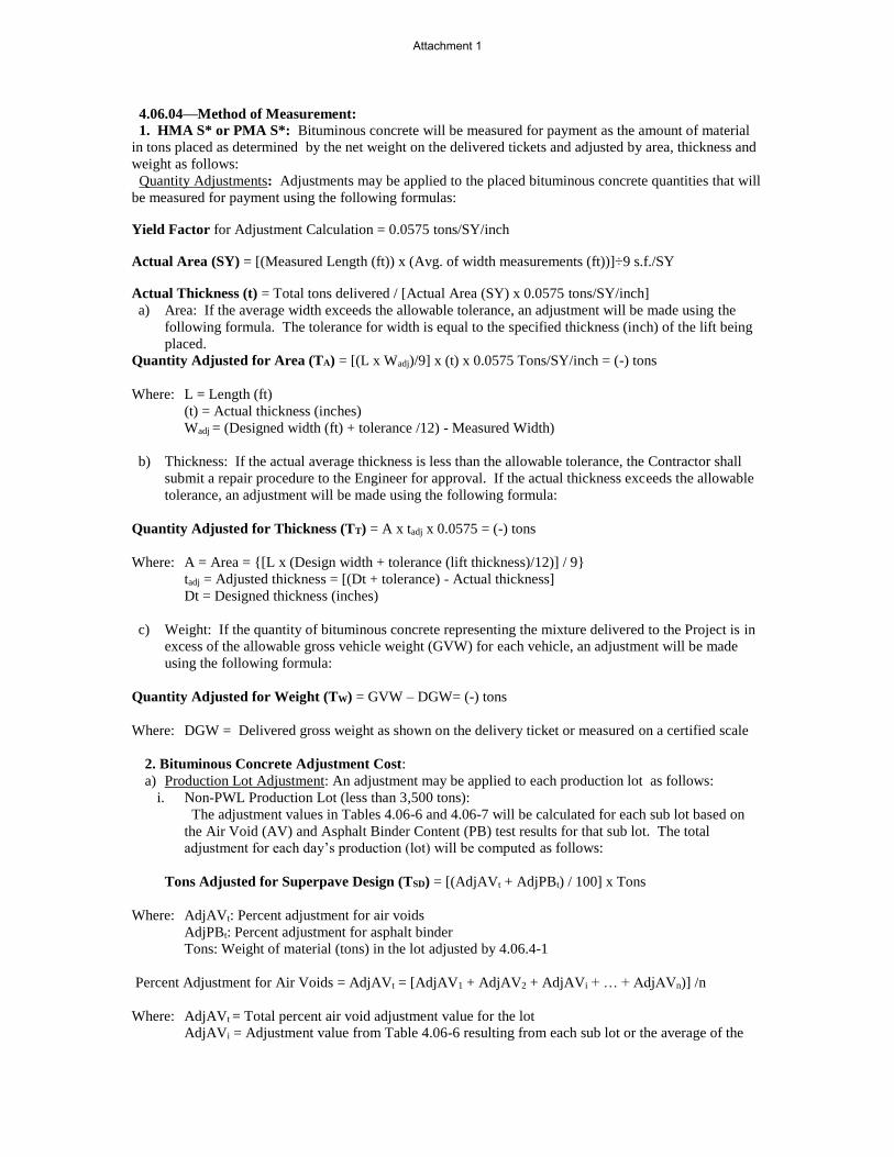
4.06.04—Method of Measurement: 1. HMA S* or PMA S*: Bituminous concrete will be measured for payment as the amount of material
in tons placed as determined by the net weight on the delivered tickets and adjusted by area, thickness and
weight as follows:
Quantity Adjustments: Adjustments may be applied to the placed bituminous concrete quantities that will
be measured for payment using the following formulas:
Yield Factor for Adjustment Calculation = 0.0575 tons/SY/inch
Actual Area (SY) = [(Measured Length (ft)) x (Avg. of width measurements (ft))]÷9 s.f./SY
Actual Thickness (t) = Total tons delivered / [Actual Area (SY) x 0.0575 tons/SY/inch]
a) Area: If the average width exceeds the allowable tolerance, an adjustment will be made using the
following formula. The tolerance for width is equal to the specified thickness (inch) of the lift being
placed.
Quantity Adjusted for Area (TA) = [(L x Wadj)/9] x (t) x 0.0575 Tons/SY/inch = (-) tons
Where: L = Length (ft)
(t) = Actual thickness (inches)
Wadj = (Designed width (ft) + tolerance /12) - Measured Width)
b) Thickness: If the actual average thickness is less than the allowable tolerance, the Contractor shall
submit a repair procedure to the Engineer for approval. If the actual thickness exceeds the allowable
tolerance, an adjustment will be made using the following formula:
Quantity Adjusted for Thickness (TT) = A x tadj x 0.0575 = (-) tons
Where: A = Area = {[L x (Design width + tolerance (lift thickness)/12)] / 9}
tadj = Adjusted thickness = [(Dt + tolerance) - Actual thickness]
Dt = Designed thickness (inches)
c) Weight: If the quantity of bituminous concrete representing the mixture delivered to the Project is in
excess of the allowable gross vehicle weight (GVW) for each vehicle, an adjustment will be made
using the following formula:
Quantity Adjusted for Weight (TW) = GVW – DGW= (-) tons
Where: DGW = Delivered gross weight as shown on the delivery ticket or measured on a certified scale
2. Bituminous Concrete Adjustment Cost:
a) Production Lot Adjustment: An adjustment may be applied to each production lot as follows:
i. Non-PWL Production Lot (less than 3,500 tons):
The adjustment values in Tables 4.06-6 and 4.06-7 will be calculated for each sub lot based on
the Air Void (AV) and Asphalt Binder Content (PB) test results for that sub lot. The total
adjustment for each day’s production (lot) will be computed as follows:
Tons Adjusted for Superpave Design (TSD) = [(AdjAVt + AdjPBt) / 100] x Tons
Where: AdjAVt: Percent adjustment for air voids
AdjPBt: Percent adjustment for asphalt binder
Tons: Weight of material (tons) in the lot adjusted by 4.06.4-1
Percent Adjustment for Air Voids = AdjAVt = [AdjAV1 + AdjAV2 + AdjAVi + … + AdjAVn)] /n
Where: AdjAVt = Total percent air void adjustment value for the lot
AdjAVi = Adjustment value from Table 4.06-6 resulting from each sub lot or the average of the
Attachment 1

adjustment values resulting from multiple tests within a sub lot, as approved by the Engineer.
n = number of sub lots based on Table M.04.03-2
TABLE 4.06-6: Adjustment Values for Air Voids
Percent Adjustment for Asphalt Binder = AdjPBt = [(AdjPB1 + AdjPB2 + AdjPBi + … + AdjPBn)] /n
Where: AdjPBt= Total percent liquid binder adjustment value for the lot
AdjPBi = Adjustment value from Table 4.06-7 resulting from each sub lot
n = number of binder tests in a production lot
TABLE 4.06-7: Adjustment Values for Binder Content
Adjustment Value
(AdjAVi) (%)
S0.25, S0.375, S0.5, S1
Pb
0.0 JMF Pb ± 0.3
- 10.0 ≤ JMF Pb - 0.4 or ≥ JMF Pb + 0.4
ii. PWL Production Lot (3500 tons or more):
For each lot, the adjustment values will be calculated using PWL methodology based on AV,
VMA, and PB test results. The results will be considered as being normally distributed and all
applicable equations in AASHTO R 9 and AASHTO R 42 Appendix X4 will apply.
Only one test result will be considered for each sub lot. The specification limits are listed in
M.04.
For AV, PB, and voids in mineral aggregate (VMA), the individual material quantity
characteristic adjustment (Adj) will be calculated as follows:
For PWL between 50 and 90%: Adj(AVt or PBt or VMAt)= (55 + 0.5 PWL) - 100
For PWL at and above 90%: Adj(AVt or PBt or VMAt)= (77.5 + 0.25 PWL) - 100
Where: AdjAVt = Total percent AV adjustment value for the lot
AdjPBt= Total percent PB adjustment value for the lot
AdjVMAt= Total percent VMA adjustment value for the lot
A lot with PWL less than 50% in any of the 3 individual material quality characteristics will be
evaluated under 1.06.04.
The total adjustment for each production lot will be computed using the following formula:
Tons Adjusted for Superpave Design (TSD) = [(0.5AdjAVt + 0.25AdjPBt + 0.25 AdjVMAt) / 100] X Tons
Where Tons: Weight of material (tons) in the lot adjusted by 4.06.4-1
iii. Partial Lots:
Lots with less than 4 sub lots will be combined with the prior lot. If there is no prior lot with
equivalent material or if the last test result of the prior lot is over 30 calendar days old, the adjustment
will be calculated as indicated in 4.06.04-2.a)i.
Lots with 4 or more sub lots will be calculated as indicated in 4.06.04-2.a)ii.
Production Lot Adjustment: TSD x Unit Price = Est. (Pi)
Adjustment Value
(AdjAVi) (%)
S0.25, S0.375, S0.5, S1
Air Voids (AV)
+2.5 3.8 - 4.2
+3.125*(AV-3) 3.0 - 3.7
-3.125*(AV-5) 4.3 – 5.0
20*(AV-3) 2.3 – 2.9
-20*(AV-5) 5.1 – 5.7
-20.0 ≤ 2.2 or ≥ 5.8
Attachment 1

Where: Unit Price = Contract unit price per ton per type of mixture
Est. ( Pi)= Pay Unit in dollars representing incentive or disincentive per lot
b) Density Lot Adjustment: An adjustment may be applied to each density lot as follows:
i. Simple Average Density Lot (less than 3500 tons) and Bridge Lots:
The final lot quantity shall be the difference between the total payable tons for the Project and the
sum of the previous lots. If either the Mat or Joint adjustment value is “remove and replace,” the
density lot shall be removed and replaced (curb to curb).
No positive adjustment will be applied to a density lot in which any core was not taken within the
required 5 calendar days of placement.
Tons Adjusted for Density (TD) = [{(PAM x 0.50) + (PAJ x 0.50)} / 100] X Tons
Where: TD = Total tons adjusted for density for each lot
PAM = Mat density percent adjustment from Table 4.06-8
PAJ = Joint density percent adjustment from Table 4.06-9
Tons: Weight of material (tons) in the lot adjusted by 4.06.4-1
TABLE 4.06-8: Adjustment Values for Pavement Mat density
Average Core Result Percent Adjustment (Bridge and Non-Bridge) (1)(2)
Percent Mat Density
97.1 - 100 -1.667*(ACRPD-98.5)
94.5 – 97.0 +2.5
93.5 – 94.4 +2.5*(ACRPD-93.5)
92.0 – 93.4 0
90.0 – 91.9 -5*(92-ACRPD)
88.0 – 89.9 -10*(91-ACRPD)
87.0 – 87.9 -30
86.9 or less Remove and Replace (curb to curb)
Notes: (1) ACRPD = Average Core Result Percent Density (2) All Percent Adjustments to be rounded to the second decimal place; for example round 1.667 to 1.67.
TABLE 4.06-9: Adjustment Values for Pavement Joint Density
Average Core Result Percent Adjustment (Bridge and Non-Bridge) (1)(2)
Percent Joint Density
97.1 – 100 -1.667*(ACRPD-98.5)
93.5 – 97.0 +2.5
92.0 – 93.4 +1.667*(ACRPD-92)
91.0 – 91.9 0
89.0 – 90.9 -7.5*(91-ACRPD)
88.0 – 88.9 -15*(90-ACRPD)
87.0 – 87.9 -30
86.9 or less Remove and Replace (curb to curb)
Notes: (1) ACRPD = Average Core Result Percent Density (2) All Percent Adjustments to be rounded to the second decimal place; for example round 1.667 to 1.67
Additionally, any sublot with a density result below 87% will be evaluated under 1.06.04.
Attachment 1

ii. PWL Density Lot (3,500 tons or more):
For each lot, the adjustment values will be calculated using PWL methodology based on mat and
joint density test results. Only one result will be included for each sublot. The results will be
considered as being normally distributed and all applicable equations in AASHTO R 9 and
AASHTO R 42 Appendix X4 will apply.
The specification limits for the PWL determination are as follows:
Mat Density: 91.5-98%
Joint Density: 90-98%
For mat and joint density, the individual percent adjustment (PA) will be calculated as follows:
For PWL between 50 and 90%: PA (M or J)= 0.25 * PWL – 22.50
For PWL at and above 90%: PA (M or J)= 0.125 * PWL – 11.25
Where: PAM = Total percent mat density adjustment value for the PWL mat density lot
PAJ= Total percent joint density adjustment value for the PWL joint density lot
No positive adjustment will be applied to a density lot in which any core was not taken within the
required 5 calendar days of placement.
A lot with PWL less than 50% will be evaluated under 1.06.04.
The total adjustment for each PWL mat density lot will be computed as follows:
Tons Adjusted for Mat Density (TMD) = (PAM / 100) X Tons
Where: Tons= Weight of material (tons) in the lot adjusted by 4.06.4-1.
The total adjustment for each PWL joint density lot will be computed as follows:
Tons Adjusted for Joint Density (TJD) = (PAJ / 100) X J_Tons
Tons Adjusted for Joint Density will be calculated at the end of each project or project phase.
Where: J_Tons = Tons in project or phase adjusted by 4.06.4 − 1 x Lot joint length
Joint length in project or phase
All bridge density lot adjustments will be evaluated in accordance with 4.06.04-2.b)i.
Additionally, any sublot with a density result below 87% will be evaluated under 1.06.04.
iii. Partial Lots:
Lots with less than 4 sub lots will be combined with the prior lot. If there is no prior lot with
equivalent material and placement conditions or if the last test result of the prior lot is over 30
calendar days old, the mat and joint individual adjustments will be calculated in accordance to
Tables 4.06-8 and 4.06-9. TMD and TJD will be calculated as indicated in 4.06.04-2.b)i.
Lots with 4 or more sub lots will be calculated as indicated in 4.06.04-2.b)ii.
Density Lot Adjustment (Simple Average Lots): TD x Unit Price = Est. (Di)
Density Lot Adjustment (PWL Lots): (TMD or TJD) x Unit Price = Est. (DMi or DJi)
Where: Unit Price = Contract unit price per ton per type of mixture
Est. (Di)= Pay Unit in dollars representing incentive or disincentive per simple average
density lot
Est. (DMi)= Pay Unit in dollars representing incentive or disincentive per PWL mat lot
Est. (DJi)= Pay Unit in dollars representing incentive or disincentive per PWL joint lot
Additionally, any sublot with a density result below 87% will be evaluated under 1.06.04.
3. Transitions for Roadway Surface: The installation of permanent transitions will be measured under
the appropriate item used in the formation of the transition.
The quantity of material used for the installation of temporary transitions will be measured for payment
Attachment 1

under the appropriate item used in the formation of the transition. The installation and removal of a bond
breaker and the removal and disposal of any temporary transition formed by milling or with bituminous
concrete pavement is not measured for payment.
4. Cut Bituminous Concrete Pavement: The quantity of bituminous concrete pavement cut will be
measured in accordance with 2.02.04.
5. Material for Tack Coat: The quantity of tack coat will be measured for payment by the number of
gallons furnished and applied on the Project and approved by the Engineer. No tack coat material shall be
included that is placed in excess of the tolerance described in 4.06.03.
a. Container Method – Material furnished in a container will be measured to the nearest 1/2 gallon. The
volume will be determined by either measuring the volume in the original container by a method
approved by the Engineer or using a separate graduated container capable of measuring the volume to
the nearest 1/2 gallon. The container in which the material is furnished must include the description
of material, including lot number or batch number and manufacturer or product source.
b. Vehicle Method
i. Measured by Weight: The number of gallons furnished will be determined by weighing
the material on calibrated scales furnished by the Contractor. To convert weight to
gallons, one of the following formulas will be used:
Tack Coat (gallons at 60°F) = Measured Weight (pounds) / Weight per gallon at 60°F
Tack Coat (gallons at 60°F) = 0.996 x Measured Weight (pounds) / Weight per gallon at 77°F
ii. Measured by automated metering system on the delivery vehicle:
Tack Coat (gallons at 60°F) = 0.976 x Measured Volume (gallons).
6. Material Transfer Vehicle (MTV): The furnishing and use of a MTV will be measured separately
for payment based on the actual number of surface course tons delivered to a paver using the MTV.
4.06.05—Basis of Payment: 1. HMA S* or PMA S*: The furnishing and placing of bituminous concrete will be paid for at the
Contract unit price per ton for " HMA S*" or " PMA S*."
All costs associated with providing illumination of the work area are included in the general cost of the
work.
All costs associated with cleaning the surface to be paved, including mechanical sweeping, are included in
the general cost of the work. All costs associated with constructing longitudinal joints are included in the
general cost of the work.
All costs associated with obtaining cores for acceptance testing and dispute resolution are included in the
general cost of the work.
2. Bituminous Concrete Adjustment Costs: This adjustment will be calculated using the formulas
shown below if all of the measured adjustments in 4.06.04-2 are not equal to zero. A positive or negative
adjustment will be applied to monies due the Contractor.
Production Lot: Ʃ Est (Pi) = Est. (P)
Density Lot (Simple Average Lots): Ʃ Est (Di) = Est. (D)
Density Lot (PWL): Ʃ Est (DMi) + Ʃ (DJi) = Est. (D)
Bituminous Concrete Adjustment Cost= Est. (P) + Est. (D)
Where: Est. ( )= Pay Unit in dollars representing incentive or disincentive in each production or
density lot calculated in 4.06.04-2
The Bituminous Concrete Adjustment Cost item, if included in the bid proposal or estimate, is not to be
altered in any manner by the Bidder. If the Bidder should alter the amount shown, the altered figure will be
disregarded and the original estimated cost will be used for the Contract.
3. Transitions for Roadway Surface: The installation of permanent transitions will be paid under the
appropriate item used in the formation of the transition. The quantity of material used for the installation of
temporary transitions will be paid under the appropriate pay item used in the formation of the transition.
The installation and removal of a bond breaker, and the removal and disposal of any temporary transition
formed by milling or with bituminous concrete pavement is included in the general cost of the work.
4. The cutting of bituminous concrete pavement will be paid in accordance with 2.02.05.
5. Material for tack coat will be paid for at the Contract unit price per gallon at 60°F for "Material for
Attachment 1

Tack Coat."
6. The Material Transfer Vehicle (MTV) will be paid at the Contract unit price per ton for "Material
Transfer Vehicle."
Pay Item Pay Unit
HMA S* ton
PMA S* ton
Bituminous Concrete Adjustment Cost est.
Material for Tack Coat gal.
Material Transfer Vehicle ton
Attachment 1

Rev. 7-18-16
ITEM #0406999A
ITEM #0406999A - ASPHALT ADJUSTMENT COST
Description: The Asphalt Adjustment Cost will be based on the variance in price for the
performance-graded binder component of hot mix asphalt (HMA), Polymer Modified Asphalt
(PMA), and Ultra-Thin Bonded Hot-Mix Asphalt mixtures completed and accepted during the
Contract.
The Asphalt Price is available on the Department of Transportation website at:
http://www.ct.gov/dot/asphaltadjustment
Construction Methods:
An asphalt adjustment will be applied only if all of the following conditions are met:
I. For HMA and PMA mixtures:
a. The HMA or PMA mixture for which the adjustment would be applied is listed as a
Contract item with a pay unit of tons.
b. The total quantity for all HMA and PMA mixtures in the Contract or individual
purchase order (Department of Administrative Service contract awards) exceeds
1000 tons or the Project duration is greater than 6 months.
c. The difference between the posted Asphalt Base Price and Asphalt Period Price
varies by more than $5.00 per ton.
II. For Ultra-Thin Bonded HMA mixtures:
a. The Ultra-Thin Bonded HMA mixture for which the adjustment would be applied is
listed as a Contract item.
b. The total quantity for Ultra-Thin Bonded HMA mixture in the Contract exceeds:
i. 800 tons if the Ultra-Thin Bonded HMA item has a pay unit of tons.
ii. 30,000 square yards if the Ultra-Thin Bonded HMA item has a pay unit of square
yards.
Note: The quantity of Ultra-Thin Bonded HMA measured in tons shall be
determined from the material documentation requirements set forth in the
Ultra-Thin Bonded HMA item Special Provision.
c. The difference between the posted Asphalt Base Price and Asphalt Period Price
varies by more than $5.00 per ton.
d. No Asphalt Adjustment Cost will be applied to the liquid emulsion that is specified as
part of the Ultra-Thin Bonded HMA mixture system.
III. Regardless of the binder used in all HMA or PMA mixtures, the Asphalt Adjustment Cost
will be based on PG 64-22.
The Connecticut Department of Transportation (CTDOT) will post on its website, the average
per ton selling price (asphalt price) of the performance-graded binder. The average is based on
the high and low selling price published in the most recent available issue of the Asphalt
Weekly Monitor® furnished by Poten & Partners, Inc. under the “East Coast Market – New
England, New Haven, Connecticut area,” F.O.B. manufacturer’s terminal.
Attachment 1

Rev. 7-18-16
ITEM #0406999A
The selling price furnished from the Asphalt Weekly Monitor ® is based on United
States dollars per standard ton (US$/ST).
Method of Measurement:
where
HMA:
1. For HMA, PMA, and Ultra-Thin Bonded HMA mixtures with pay units of tons:
The quantity in tons of accepted HMA, PMA, or Ultra-Thin Bonded HMA
mixture measured and accepted for payment.
2. For Ultra-Thin Bonded HMA mixtures with pay units of square yards:
The quantity of Ultra-Thin Bonded HMA mixture delivered, placed, and accepted
for payment, calculated in tons as documented according to the Material
Documentation provision (Construction Methods, paragraph G) of the Ultra-Thin
Bonded HMA Special Provision.
Asphalt Base Price: The asphalt price posted on the CTDOT website 28 days before
the actual bid opening posted.
Asphalt Period Price: The asphalt price posted on the CTDOT website during the
period the HMA or PMA mixture was placed.
PG%: Performance-Graded Binder percentage
1. For HMA or PMA mixes:
PG% = 4.5 for HMA S1 and PMA S1
PG% = 5.0 for HMA S0.5 and PMA S0.5
PG% = 6.0 for HMA S0.375, PMA S0.375, HMA S0.25 and PMA S0.25
2. For Ultra-Thin Bonded HMA mixes:
PG% = Design % PGB (Performance Graded Binder) in the approved job mix
formula, expressed as a percentage to the tenth place (e.g. 5.1%)
The asphalt adjustment cost shall not be considered as a changed condition in the
Contract as result of this provision since all bidders are notified before submission of
bids.
Basis of Payment: The "Asphalt Adjustment Cost" will be calculated using the formula
indicated above. A payment will be made for an increase in costs. A deduction from
monies due the Contractor will be made for a decrease in costs.
The sum of money shown on the Estimate and in the itemized proposal as "Estimated
Cost" for this item will be considered the bid price although the adjustment will be made
as described above. The estimated cost figure is not to be altered in any manner by the
bidder. If the bidder should alter the amount shown, the altered figure will be
disregarded and the original cost figure will be used to determine the amount of the bid
for the Contract.
Pay Item Pay Unit
Asphalt Adjustment Cost est.
Formula: HMA X [PG%/100] x [(Period Price - Base Price)] = $ ____
Attachment 1
STATE OF CONNECTICUT
Regulation of Environmental Protection
Section 22a-174-20 of the Regulations of Connecticut
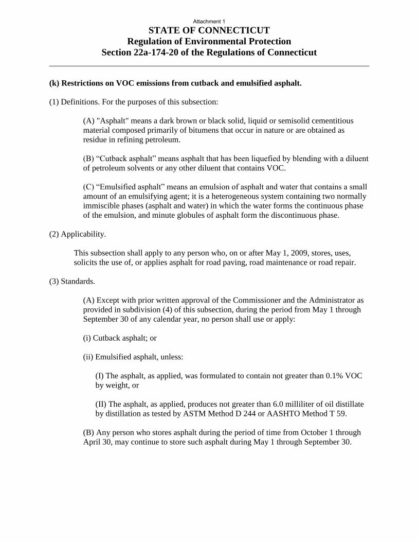
(k) Restrictions on VOC emissions from cutback and emulsified asphalt.
(1) Definitions. For the purposes of this subsection:
(A) "Asphalt" means a dark brown or black solid, liquid or semisolid cementitious
material composed primarily of bitumens that occur in nature or are obtained as
residue in refining petroleum.
(B) “Cutback asphalt” means asphalt that has been liquefied by blending with a diluent
of petroleum solvents or any other diluent that contains VOC.
(C) “Emulsified asphalt” means an emulsion of asphalt and water that contains a small
amount of an emulsifying agent; it is a heterogeneous system containing two normally
immiscible phases (asphalt and water) in which the water forms the continuous phase
of the emulsion, and minute globules of asphalt form the discontinuous phase.
(2) Applicability.
This subsection shall apply to any person who, on or after May 1, 2009, stores, uses,
solicits the use of, or applies asphalt for road paving, road maintenance or road repair.
(3) Standards.
(A) Except with prior written approval of the Commissioner and the Administrator as
provided in subdivision (4) of this subsection, during the period from May 1 through
September 30 of any calendar year, no person shall use or apply:
(i) Cutback asphalt; or
(ii) Emulsified asphalt, unless:
(I) The asphalt, as applied, was formulated to contain not greater than 0.1% VOC
by weight, or
(II) The asphalt, as applied, produces not greater than 6.0 milliliter of oil distillate
by distillation as tested by ASTM Method D 244 or AASHTO Method T 59.
(B) Any person who stores asphalt during the period of time from October 1 through
April 30, may continue to store such asphalt during May 1 through September 30.
Attachment 1

STATE OF CONNECTICUT
Regulation of Environmental Protection
Section 22a-174-20 of the Regulations of Connecticut
(4) Exceptions.
(A) The use or application of cutback asphalt or emulsified asphalt that does not
comply with subdivision (3) of this subsection may be allowed upon obtaining
approval from the Commissioner and the Administrator.
(B) Any request for an approval under this subdivision shall be made in writing to the
Commissioner and the Administrator and shall include, at a minimum, the following
information:
(i) The scope of the activity,
(ii) An assessment of alternative materials and procedures,
(iii) Quantification of the amount of VOC that would be emitted as a result of such
activity,
(iv) The dates during which the activity will occur, and
(v) A demonstration that it is necessary for the activity to occur during the period
commencing on May 1 and ending after September 30.
(5) Recordkeeping.
(A) Any person subject to this subsection shall:
(i) Maintain records of test, formulation, and usage data, and any other information
necessary for the Commissioner to determine compliance with the requirements of
this subsection,
(ii) Maintain all records required pursuant to this subsection in a readily accessible
location in Connecticut for a minimum of five (5) years, and
(iii) Provide records made pursuant to this subsection to the Commissioner not
later than thirty (30) days after a request to provide such records.
(B) Any person who has obtained approval for a non-complying use pursuant to
subdivision (4) of this subsection shall maintain copies of the request, all supporting
materials and the written approval of the Commissioner.
Attachment 1

SECTION M.04
BITUMINOUS CONCRETE MATERIALS
M.04.01—Bituminous Concrete Materials and Facilities
M.04.02—Mix Design and Job Mix Formula (JMF)
M.04.03—Production Requirements
M.04.01—Bituminous Concrete Materials and Facilities: Each source of material, Plant, and
laboratory used to produce and test bituminous concrete must be qualified on an annual basis by the
Engineer. AASHTO or ASTM Standards noted with an (M) have been modified and are detailed in
Table M.04.03-5.
Aggregates from multiple sources of supply must not be blended or stored in the same stockpile.
1. Coarse Aggregate: All coarse aggregate shall meet the requirements listed in M.01.
2. Fine Aggregate: All fine aggregate shall meet the requirements listed in M.01.
3. Mineral Filler: Mineral filler shall conform to the requirements of AASHTO M 17.
4. Performance Graded (PG) Asphalt Binder: (a) General:
i. PG asphalt binder shall be uniformly mixed and blended and be free of contaminants such as
fuel oils and other solvents. Binder shall be properly heated and stored to prevent damage or
separation.
ii. The binder shall meet the requirements of AASHTO M 332 and shall be graded or verified in
accordance with AASHTO R 29. The Contractor shall submit a Certified Test Report and bill of
lading representing each delivery in accordance with AASHTO R 26(M). The Certified Test
Report must also indicate the binder specific gravity at 77°F; rotational viscosity at 275°F and
329°F; and the mixing and compaction viscosity-temperature chart for each shipment.
iii. The Contractor shall submit the name(s) of personnel responsible for receipt, inspection, and
record keeping of PG binder. Contractor Plant personnel shall document specific storage tank(s)
where binder will be transferred and stored until used and provide binder samples to the
Engineer upon request. The person(s) shall assure that each shipment is accompanied by a
statement certifying that the transport vehicle was inspected before loading was found acceptable
for the material shipped and that the binder is free of contamination from any residual material,
along with 2 copies of the bill of lading.
iv. The blending or combining of PG binders in 1 storage tank at the Plant from different suppliers,
grades, or additive percentages is prohibited.
(b) Basis of Approval: The request for approval of the source of supply shall list the location where the
material will be manufactured, and the handling and storage methods, along with necessary certification
in accordance with AASHTO R 26(M). Only suppliers/refineries that have an approved “Quality Control
Plan for Performance Graded Binders” formatted in accordance with AASHTO R 26(M) may supply PG
binders to Department projects.
(c) Standard Performance Grade (PG) Binder:
i. Standard PG binder shall be defined as “Neat.” Neat PG binders shall be free from modification
with: fillers, extenders, reinforcing agents, adhesion promoters, thermoplastic polymers, acid
modification and other additives such as re-refined motor oil, and shall indicate such information
on each bill of lading and Certified Test Report.
ii. The standard asphalt binder shall be PG 64S-22.
(d) Modified Performance Grade (PG) Binder: The modified asphalt binder shall be Performance
Grade PG 64E-22 asphalt modified solely with a Styrene-Butadiene-Styrene (SBS) polymer. The
polymer modifier shall be added at either the refinery or terminal and delivered to the bituminous
concrete production facility as homogenous blend. The stability of the modified binder shall be verified
in accordance with ASTM D7173 using the Dynamic Shear Rheometer (DSR). The DSR G*/sin(δ)
results from the top and bottom sections of the ASTM D7173 test shall not differ by more than 10%. The
results of ASTM D7173 shall be included on the Certified Test Report. The binder shall meet the
requirements of AASHTO M 332 (including Appendix X1) and AASHTO R 29.
(e) Warm Mix Additive or Technology:
i. The warm mix additive or technology must be listed on the North East Asphalt User Producer
Group (NEAUPG) Qualified Warm Mix Asphalt (WMA) Technologies List at the time of bid,
which may be accessed online at http://www.neaupg.uconn.edu.
ii. The warm mix additive shall be blended with the asphalt binder in accordance with the
manufacturer’s recommendations.
iii. The blended binder shall meet the requirements of AASHTO M 332 and shall be graded or
verified in accordance with AASHTO R 29 for the specified binder grade. The Contractor shall
submit a Certified Test Report showing the results of the testing demonstrating the binder grade.
Attachment 1

In addition, it must include the grade of the virgin binder, the brand name of the warm mix
additive, the manufacturer’s suggested rate for the WMA additive, the water injection rate (when
applicable), and the WMA Technology manufacturer’s recommended mixing and compaction
temperature ranges.
5. Emulsified Asphalts:
(a) General:
i. The emulsified asphalt shall meet the requirements of AASHTO M 140(M) or AASHTO M 208
as applicable.
ii. The emulsified asphalts shall be free of contaminants such as fuel oils and other solvents.
iii. The blending at mixing Plants of emulsified asphalts from different suppliers is prohibited.
(b) Basis of Approval:
i. The request for approval of the source of supply shall list the location where the material is
manufactured, the handling and storage methods, and certifications in accordance with
AASHTO R 77. Only suppliers that have an approved “Quality Control Plan for Emulsified
Asphalt” formatted in accordance with AASHTO R 77 and that submit monthly split samples
per grade to the Engineer may supply emulsified asphalt to Department projects.
ii. Each shipment of emulsified asphalt delivered to the Project site shall be accompanied with the
corresponding Certified Test Report listing Saybolt viscosity, residue by evaporation,
penetration of residue, and weight per gallon at 77°F and Material Certificate.
iii. Anionic emulsified asphalts shall meet the requirements of AASHTO M-140. Materials used for
tack coat shall not be diluted and meet grade RS-1 or RS-1h. When ambient temperatures are
80°F and rising, grade SS-1 or SS-1h may be substituted if permitted by the Engineer.
iv. Cationic emulsified asphalt shall meet the requirements of AASHTO M-208. Materials used for
tack coat shall not be diluted and meet grade CRS-1. The settlement and demulsibility test will
not be performed unless deemed necessary by the Engineer. When ambient temperatures are
80°F and rising, grade CSS-1 or CSS-1h may be substituted if permitted by the Engineer.
6. Reclaimed Asphalt Pavement (RAP):
(a) General: RAP is a material obtained from the cold milling or removal and processing of bituminous
concrete pavement. RAP material shall be crushed to 100% passing the 1/2 inch sieve and free from
contaminants such as joint compound, wood, plastic, and metals.
(b) Basis of Approval: The RAP material will be accepted on the basis of one of the following criteria:
i. When the source of all RAP material is from pavements previously constructed on Department
projects, the Contractor shall provide a Materials Certificate listing the detailed locations and
lengths of those pavements and that the RAP is only from those locations listed.
ii. When the RAP material source or quality is not known, the Contractor shall request approval
from the Engineer at least 30 calendar days prior to the start of the paving operation. The
request shall include a Material Certificate and applicable test results stating that the RAP
consists of aggregates that meet the specification requirements of M.04.01-1 through M.04.01-3
and that the binder in the RAP is substantially free of solvents, tars and other contaminants. The
Contractor is prohibited from using unapproved material on Department projects and shall take
necessary action to prevent contamination of approved RAP stockpiles. Stockpiles of
unapproved material shall remain separate from all other RAP materials at all times. The request
for approval shall include the following:
1. A 50-lb. sample of the RAP to be incorporated into the recycled mixture.
2. A 25-lb. sample of the extracted aggregate from the RAP.
7. Crushed Recycled Container Glass (CRCG): (a) Requirements: The Contractor may propose to use clean and environmentally-acceptable CRCG in
an amount not greater than 5% by weight of total aggregate.
(b) Basis of Approval: The Contractor shall submit to the Engineer a request to use CRCG. The
request shall state that the CRCG contains no more than 1% by weight of contaminants such as paper,
plastic, and metal and conforms to the following gradation:
CRCG Grading Requirements
Sieve Size Percent Passing
3/8 inch 100
No. 4 35-100
No. 200 0.0-10.0
The Contractor shall submit a Material Certificate to the Engineer stating that the CRCG complies with
all the applicable requirements in this Section.
8. Joint Seal Material: Joint seal material must meet the requirements of ASTM D6690 - Type 2. The
Attachment 1

Contractor shall submit a Material Certificate in accordance with 1.06.07 certifying that the joint seal
material meets the requirements of this Section.
9. Recycled Asphalt Shingles (RAS): RAS shall consist of processed asphalt roofing shingles from
post-consumer asphalt shingles or from manufactured shingle waste. The RAS material under
consideration for use in bituminous concrete mixtures must be certified as being asbestos-free and shall
be entirely free of whole, intact nails. The RAS material shall meet the requirements of AASHTO MP
23.
The Producer shall test the RAS material to determine the asphalt content and the gradation of the RAS
material. The Producer shall take necessary action to prevent contamination of RAS stockpiles.
The Contractor shall submit a Material Certificate to the Engineer stating that the RAS complies with all
the applicable requirements in this Section.
10. Plant Requirements: (a) General: The Plant producing bituminous concrete shall comply with AASHTO M 156.
(b) Storage Silos: The Contractor may use silos for short-term storage with the approval of the
Engineer. A storage silo must have heated cones and an unheated silo cylinder if it does not contain a
separate internal heating system. When multiple silos are filled, the Contractor shall discharge 1 silo at a
time. Simultaneous discharge of multiple silos for the same Project is not permitted.
Type of silo cylinder Maximum storage time for all classes (hr)
HMA WMA/PMA
Open Surge 4 Mfg Recommendations*
Unheated - Non-insulated 8 Mfg Recommendations*
Unheated - Insulated 18 Mfg Recommendations*
Heated - No inert gas TBD by the Engineer TBD by the Engineer
*Not to exceed HMA limits
(c) Documentation System: The mixing Plant documentation system shall include equipment for
accurately proportioning the components of the mixture by weight and in the proper order, controlling the
cycle sequence, and timing the mixing operations. Recording equipment shall monitor the batching
sequence of each component of the mixture and produce a printed record of these operations on each
Plant ticket, as specified herein.
If recycled materials are used, the Plant tickets shall include their dry weight, percentage, and daily
moisture content.
If a WMA Technology is added at the Plant, the Plant tickets shall include the actual dosage rate.
For drum Plants, the Plant ticket shall be produced at 5 minute intervals and maintained by the vendor
for a period of 3 years after the completion of the Project.
For batch Plants, the Plant ticket shall be produced for each bath and maintained by the vendor for a
period of 3 years after the completion of the Project. In addition, an asterisk (*) shall be automatically
printed next to any individual batch weight(s) exceeding the following tolerances:
Each Aggregate Component ±1.5% of individual or cumulative
target weight for each bin
Mineral Filler ±0.5% of the total batch
Bituminous Material ±0.1% of the total batch
Zero Return (Aggregate) ±0.5% of the total batch
Zero Return
(Bituminous Material) ±0.1% of the total batch
The entire batching and mixing interlock cut-off circuits shall interrupt and stop the automatic batching
operations when an error exceeding the acceptable tolerance occurs in proportioning.
The scales shall not be manually adjusted during the printing process. In addition, the system shall be
interlocked to allow printing only when the scale has come to a complete rest. A unique printed character
(m) shall automatically be printed on the truck and batch plant printout when the automatic batching
Attachment 1

sequence is interrupted or switched to auto-manual or full manual during proportioning.
(d) Aggregates: Aggregate stockpiles shall be managed to prevent segregation and cross
contamination. For drum Plants only, the percent moisture content, at a minimum prior to production and
half way through production, shall be determined.
(e) Mixture: The dry and wet mix times shall be sufficient to provide a uniform mixture and a
minimum particle coating of 95% as determined by AASTO T 195(M).
Bituminous concrete mixtures shall contain no more than 0.5% moisture when tested in accordance with
AASHTO T 329.
(f) RAP: RAP moisture content shall be determined a minimum of twice daily (prior to production and
halfway through production).
(g) Asphalt Binder: A binder log shall be submitted to the Department’s Central Lab on a monthly
basis.
(h) Warm mix additive: For mechanically foamed WMA, the water injection rate shall be monitored
during production and not exceed 2.0% by total weight of binder. For additive added at the Plant, the
dosage rate shall be monitored during production.
(i) Testing Laboratory: The Contractor shall maintain a laboratory to test bituminous concrete mixtures
during production. The laboratory shall have a minimum of 300 s.f., have a potable water source and
drainage in accordance with the CT Department of Public Health Drinking Water Division, and be
equipped with all necessary testing equipment as well as with a PC, printer, and telephone with a
dedicated hard-wired phone line. In addition, the PC shall have a high speed internet connection and a
functioning web browser with unrestricted access to https://ctmail.ct.gov . This equipment shall be
maintained in working order at all times and be made available for use by the Engineer.
The laboratory shall be equipped with a heating system capable of maintaining a minimum temperature
of 65°F. It shall be clean and free of all materials and equipment not associated with the laboratory.
Sufficient light and ventilation must be provided. During summer months adequate cooling or ventilation
must be provided so the indoor air temperature shall not exceed the ambient outdoor temperature.
The laboratory testing apparatus, supplies, and safety equipment shall be capable of performing all the
applicable tests in their entirety that are referenced in AASHTO R 35 and AASHTO M 323. The
Contractor shall ensure that the Laboratory is adequately supplied at all times during the course of the
Project with all necessary testing materials and equipment.
The Contractor shall maintain a list of laboratory equipment used in the acceptance testing processes
including, but not limited to, balances, scales, manometer/vacuum gauge, thermometers, and gyratory
compactor, clearly showing calibration and/or inspection dates, in accordance with AASHTO R 18. The
Contractor shall notify the Engineer if any modifications are made to the equipment within the laboratory.
The Contractor shall take immediate action to replace, repair, or recalibrate any piece of equipment that is
out of calibration, malfunctioning, or not in operation.
M.04.02—Mix design and Job Mix Formula (JMF)
1. Curb Mix:
(a) Requirements: The Contractor shall use bituminous concrete that meets the requirements of Table
M.04.02-1. RAP may be used in 5% increments by weight up to 30%.
(b) Basis of Approval: Annually, an approved JMF based on a mix design for curb mix must be on file
with the Engineer prior to use.
The Contractor shall test the mixture for compliance with the submitted JMF and Table M.04.02-1. The
maximum theoretical density (Gmm) will be determined by AASHTO T 209. If the mixture does not
meet the requirements, the JMF shall be adjusted within the ranges shown in Table M.04.02-1 until an
acceptable mixture is produced.
An accepted JMF from the previous operating season may be acceptable to the Engineer provided that
there are no changes in the sources of supply for the coarse aggregate, fine aggregate, recycled material
(if applicable) and the Plant operation had been consistently producing acceptable mixture.
Any change in component source of supply or consensus properties must be approved by the Engineer.
A revised JMF shall be submitted prior to use.
Attachment 1

TABLE M.04.02-1:
Control Points for Curb Mix Mixtures
Mix Curb Mix Production Tolerances
from JMF Target
Grade of PG
Binder content %
PG 64S-22
6.5 - 9.0 0.4
Sieve Size
No. 200 3.0 - 8.0 (b) 2.0
No. 50 10 - 30 4
No. 30 20 - 40 5
No. 8 40 - 70 6
No. 4 65 - 87 7
1/4 inch
3/8 inch 95 - 100 8
1/2 inch 100 8
3/4 inch 8
1 inch
2 inch
Additionally, the fraction of material retained between any 2 consecutive sieves
shall not be less than 4%.
Mixture Temperature
Binder 325°F maximum
Aggregate 280-350°F
Mixtures 265-325°F
Mixture Properties
Air Voids (VA) % 0 – 4.0 (a)
Notes: (a) Compaction Parameter 50 gyrations (Ndes)
(b) The percent passing the No. 200 sieve shall not exceed the percentage of
bituminous asphalt binder.
2. Superpave Design Method – S0.25, S0.375, S0.5, and S1:
(a) Requirements: All designated mixes shall be designed using the Superpave mix design method in
accordance with AASHTO R 35. A JMF based on the mix design shall meet the requirements of Tables
M.04.02-2 to M.04.02-5. Each JMF and component samples must be submitted no less than 7 days prior
to production and must be approved by the Engineer prior to use. All JMFs expire at the end of the
calendar year.
All aggregate component consensus properties and tensile strength ratio (TSR) specimens shall be tested
at an AASHTO Materials Reference Laboratory (AMRL) by NETTCP Certified Technicians.
All bituminous concrete mixes shall be tested for stripping susceptibility by performing the TSR test
procedure in accordance with AASHTO T 283(M) at a minimum every 36 months. The compacted
specimens may be fabricated at the Plant and then tested at an AMRL accredited facility. A minimum of
45000 grams of laboratory or plant blended mixture and the corresponding complete Form MAT-412s
shall be submitted to the Division of Material Testing (DMT) for design TSR testing verification. The
mixture submitted shall be representative of the corresponding mix design as determined by the Engineer.
i. Superpave Mixtures with RAP: RAP may be used with the following conditions:
RAP amounts up to 15% may be used with no binder grade modification.
RAP amounts up to 20% may be used provided a new JMF is approved by the Engineer. The
JMF submittal shall include the grade of virgin binder added. The JMF shall be accompanied
by a blending chart and supporting test results in accordance with AASHTO M 323
Appendix X1, or by testing that shows the combined binder (recovered binder from the RAP,
virgin binder at the mix design proportions, warm mix asphalt additive and any other
modifier if used) meets the requirements of the specified binder grade.
Two (2) representative samples of RAP shall be obtained. Each sample shall be split, and 1
Attachment 1

split sample shall be tested for binder content in accordance with AASHTO T 164 and the
other in accordance with AASHTO T 308.
RAP material shall not be used with any other recycling option.
ii. Superpave Mixtures with RAS: RAS may be used solely in HMA S1 mixtures with the
following conditions:
RAS amounts up to 3% may be used.
RAS total binder replacement up to 15% may be used with no binder grade modification.
RAS total binder replacement up to 20% may be used provided a new JMF is approved by
the Engineer. The JMF submittal shall include the grade of virgin binder added. The JMF
shall be accompanied by a blending chart and supporting test results in accordance with
AASHTO M 323 Appendix X1, or by testing that shows the combined binder (recovered
binder from the RAP, virgin binder at the mix design proportions, warm mix asphalt additive
and any other modifier if used) meets the requirements of the specified binder grade.
Superpave Mixtures with RAS shall meet AASHTO PP 78 design considerations.
iii. Superpave Mixtures with CRCG: CRCG may be used solely in HMA S1 mixtures. One percent
(1%) of hydrated lime, or other accepted non-stripping agent, shall be added to all mixtures
containing CRCG. CRCG material shall not be used with any other recycling option.
(b) Basis of Approval: The following information must be included in the JMF submittal:
i. Gradation, consensus properties and specific gravities of the aggregate, RAP or RAS.
ii. Average asphalt content of the RAP or RAS by AASHTO T 164.
iii. Source of RAP or RAS and percentage to be used.
iv. Warm mix Technology, manufacturer’s recommended additive rate and tolerances, and
manufacturer recommended mixing and compaction temperatures.
v. TSR test report and anti-strip manufacturer and recommended dosage rate if applicable.
vi. Mixing and compaction temperature ranges for the mix with and without the warm-mix technology
incorporated.
vii. JMF ignition oven correction factor by AASHTO T 308.
With each JMF submittal, the following samples shall be submitted to the Division of Materials Testing:
4 - one (1) quart cans of PG binder, with corresponding Safety Data Sheet (SDS)
1 - 50 lbs. bag of RAP
2 - 50 lbs. bags of Plant-blended virgin aggregate
A JMF may not be approved if any of the properties of the aggregate components or mix do not meet the
verification tolerances as described in the Department’s current QA Program for Materials, Acceptance
and Assurance Testing Policies and Procedures.
Any material based on a JMF, once approved, shall only be acceptable for use when it is produced by
the designated Plant, it utilizes the same components, and the production of material continues to meet all
criteria as specified in Tables M.04.02-2, M.04.02-3 and M.04.02-4. A new JMF must be submitted to the
Engineer for approval whenever a new component source is proposed.
Only 1 mix with 1 JMF will be approved for production at a time. Switching between approved JMF
mixes with different component percentages or sources of supply is prohibited.
Attachment 1

TABLE M.04.02-2: Superpave Master Range for Bituminous Concrete Mixture Design Criteria
S0.25 S0.375 S0.5 S1
Sieve Control
Points
Control
Points
Control
Points
Control
Points
inches Min
(%)
Max
(%)
Min
(%)
Max
(%)
Min
(%)
Max
(%)
Min
(%)
Max
(%)
2.0 - - - - - - - -
1.5 - - - - - - 100 -
1.0 - - - - - - 90 100
3/4 - - - - 100 - - 90
1/2 100 - 100 - 90 100 - -
3/8 97 100 90 100 - 90 - -
No. 4 72 90 - 72 - - - -
No. 8 32 67 32 67 28 58 19 45
No. 16 - - - - - - - -
No. 30 - - - - - - - -
No. 50 - - - - - - - -
No. 100 - - - - - - - -
No. 200 2.0 10.0 2.0 10.0 2.0 10.0 1.0 7.0
VMA (%) 16.5 ± 1 16.0 ± 1 15.0 ± 1 13.0 ± 1
VA (%) 4.0 ± 1 4.0 ± 1 4.0 ± 1 4.0 ± 1
Gse JMF value JMF value JMF value JMF value
Gmm JMF ± 0.030 JMF ± 0.030 JMF ± 0.030 JMF ± 0.030
Dust / effective binder 0.6 - 1.2 0.6 - 1.2 0.6 - 1.2 0.6 - 1.2
TSR ≥ 80% ≥ 80% ≥ 80% ≥ 80%
T-283 Stripping Minimal as determined by the Engineer
(c) Mix Status: Each facility will have each type of bituminous concrete mixture rated based on the
results of the previous year of production. Mix status will be provided to each bituminous concrete
Producer prior to the beginning of the paving season.
The rating criteria are based on compliance with Air Voids and Voids in Mineral Aggregate (VMA) as
indicated in Table M.04.03-4 and are calculated as follows:
Criteria A: Percentage of acceptance test results with compliant air voids.
Criteria B: The average of the percentage of acceptance results with compliant VMA and the
percentage of acceptance results with compliant air voids.
The final rating assigned will be the lower of the rating obtained with Criteria A or Criteria B.
Mix status is defined as:
“A” – Approved: Assigned to each mixture type from a production facility with a current rating of 70%
or greater, or to each mixture type completing a successful PPT.
“PPT” – Pre-Production Trial: Temporarily assigned to each mixture type from a production facility
when:
1. there are no compliant acceptance production test results submitted to the Department from the
previous year;
Attachment 1

2. there is a source change in one or more aggregate components;
3. there is a component percentage change of more than 5% by weight;
4. there is a change in RAP percentage;
5. the mixture has a rating of less than 70% from the previous season;
6. it is a new JMF not previously submitted; or
7. the average of 10 consecutive acceptance results for VFA, Density to Nini or dust to effective
binder ratio does not meet the criteria in tables M.04.02-2 and M.04.02-4.
Bituminous concrete mixtures rated with a “PPT” status cannot be used on Department projects.
Testing shall be performed by the Producer with NETTCP certified personnel on material under this
status. Test results must confirm that specification requirements in Tables M.04.02-2 through M.04.02-4
are met and the binder content (Pb) meets the requirements in Table M.04.03-2 before material can be
used. One of the following methods must be used to verify the test results:
Option A: Schedule a day when a Department Inspector can be at the facility to witness testing
Option B: When the Contractor or their representative performs testing without being witnessed by an
Inspector, the Contractor shall submit the test results and a split sample including 2 gyratory
molds, 5,000 grams of boxed bituminous concrete, and 5,000 grams of cooled loose
bituminous concrete for verification testing and approval
Option C: When the Contractor or their representative performs testing without being witnessed by a
Department Inspector, the Engineer may verify the mix in the Contractor’s laboratory
Witnessing or verifying by the Department of compliant test results will change the mix’s status to “A
The differences between the Department’s test results and the Contractor’s must be within the “C”
tolerances included in the Department’s QA Program for Materials, Acceptance and Assurance Testing
Policies and Procedures in order to be verified.
“U” – Not Approved: Status assigned to a type of mixture that does not have an approved JMF.
Bituminous concrete mixtures with a “U” status cannot be used on Department projects.
TABLE M.04.02-3:
Superpave Consensus Properties Requirements for Combined Aggregate
Traffic
Level
Design
ESALs
(80kN)
Millions
Coarse
Aggregate
Angularity(1)
ASTM
D5821,
Minimum %
Fine
Aggregate
Angularity
AASHTO
T 304,
Method A
Minimum %
Flat and
Elongated
Particles(2)
ASTM D4791,
Maximum %
Sand
Equivalent
AASHTO
T 176,
Minimum %
1 < 0.3 55/- - 40 10 40
2 0.3 to < 3.0 75/- - 40 10 40
3 ≥ 3.0 95/90 45 10 45
Notes:
(1) 95/90 denotes that a minimum of 95% of the coarse aggregate, by mass, shall have one fractured
face and that a minimum of 90% shall have two fractured faces.
(2) Criteria presented as maximum Percent by mass of flat and elongated particles of materials retained
on the No. 4 sieve, determined at 5:1 ratio.
Attachment 1

TABLE M.04.02-4: Superpave Traffic Levels and Design Volumetric Properties
Traffic
Level
Design
ESALs
Number of
Gyrations by
Superpave
Gyratory
Compactor
Percent Density of
Gmm from HMA/
WMA Specimen
Voids Filled with Asphalt (VFA)
Based on Nominal Mix Size -
Inch
(million) Nini Ndes Nmax Nini Ndes Nmax 0.25 0.375 0.5 1
1 <0.3 6 50 75 ≤91.5 96.0 ≤98.0 70-80 70-80 70-80 67-80
2 0.3 to
<3.0 7 75 115 ≤90.5 96.0 ≤98.0 65-78 65-78 65-78 65-78
3 ≥3.0 7 75 115 ≤90.0 96.0 ≤98.0 65-77 65-76 65-75 65-75
TABLE M.04.02-5:
Superpave Minimum Binder Content by Mix Type and Level
Mix Type Level Binder Content Minimum
S0.25 1 5.80
S0.25 2 5.70
S0.25 3 5.70
S0.375 1 5.70
S0.375 2 5.60
S0.375 3 5.60
S0.5 1 5.10
S0.5 2 5.00
S0.5 3 5.00
S1 1 4.60
S1 2 4.50
S1 3 4.50
M.04.03—Production Requirements:
1. Standard Quality Control Plan (QCP) for Production: The QCP for production shall describe the
organization and procedures, which the Contractor shall use to administer quality control. The QCP shall
include the procedures used to control the production process, to determine when immediate changes to
the processes are needed, and to implement the required changes. The QCP must detail the inspection,
sampling and testing protocols to be used, and the frequency for each.
Control Chart(s) shall be developed and maintained for critical aspect(s) of the production process as
determined by the Contractor. The control chart(s) shall identify the material property, applicable upper
and lower control limits, and be updated with current test data. As a minimum, the following quality
characteristics shall be included in the control charts:
percent passing No. 4 sieve
percent passing No. 200 sieve
binder content
air voids
Gmm
Gse
VMA
The control chart(s) shall be used as part of the quality control system to document variability of the
bituminous concrete production process. The control chart(s) shall be submitted to the Engineer the first day
of each month.
The QCP shall also include the name and qualifications of a Quality Control Manager. The Quality
Attachment 1

Control Manager shall be responsible for the administration of the QCP, including compliance with the plan
and any plan modifications.
The Contractor shall submit complete production testing records to the Engineer within 24 hours in a
manner acceptable to the Engineer.
The QCP shall also include the name and qualifications of any outside testing laboratory performing any
QC functions on behalf of the Contractor. The QCP must also include a list of sampling and testing
methods and frequencies used during production, and the names of all Quality Control personnel and their
duties.
Approval of the QCP does not imply any warranty by the Engineer that adherence to the plan will result in
production of bituminous concrete that complies with these specifications. The Contractor shall submit any
changes to the QCP as work progresses.
2. Acceptance Requirements:
(a) General: A NETTCP HMA Paving Inspector certified Contractor representative shall obtain a field sample of the
material placed at the project site in accordance with AASHTO T 168 using the procedure indicated in
Section 5.2.3 or an alternate procedure approved by the Engineer. The field sample shall be quartered by
the Contractor in accordance with AASHTO R 47 and placed in an approved container. The container
shall be sealed with a security tape provided by the Department and labelled to include the project
number, date of paving, mix type, lot and sublot numbers and daily tonnage. The minimum weight of
each quartered sample shall be 14000 grams. The Contractor shall transport one of the containers to the
Departments Central Laboratory in Rocky Hill, retain one of the containers for potential use in dispute
resolution and test the remaining material for acceptance.
The Contractor shall submit all acceptance tests results to the Engineer within 24 hours or prior to the next
day’s production. All acceptance test specimens and supporting documentation must be retained by the
Contractor and may be disposed of with the approval of the Engineer. All quality control specimens shall be
clearly labeled and separated from the acceptance specimens.
Contractor personnel performing QC and acceptance testing must be present at the facility prior to, during,
and until completion of production, and be certified as a NETTCP HMA Plant Technician or Interim HMA
Plant Technician and be in good standing. Production of material for use on State projects must be
suspended by the Contractor if such personnel are not present. Technicians found by the Engineer to be
non-compliant with NETTCP policies and procedures or Department policies may be removed by the
Engineer from participating in the acceptance testing process for Department projects until their actions can
be reviewed.
Verification and dispute resolution testing will be performed by the Engineer in accordance with the
Department’s QA Program for Materials.
Should the Department be unable to validate the Contractor’s acceptance test result(s) for a lot of material,
the Engineer will use results from verification testing and re-calculate the pay adjustment for that lot. The
Contractor may request to initiate the dispute resolution process in writing within 24 hours of receiving the
adjustment and must include supporting documentation or test results to justify the request.
(b) Curb Mix Acceptance Sampling and Testing Procedures: Curb Mixes shall be tested by the Contractor
at a frequency of 1 test per every 250 tons of cumulative production, regardless of the day of production.
When these mix designs are specified, the following acceptance procedures and AASHTO test methods
shall be used:
TABLE M.04.03-1: Curb Mix Acceptance Test Procedures
Protocol Reference Description
1 AASHTO T 30(M) Mechanical Analysis of Extracted Aggregate
2 AASHTO T 168 Sampling of Bituminous Concrete
3 AASHTO T 308 Binder Content by Ignition Oven Method (adjusted for aggregate
correction factor)
4 AASHTO T 209(M)(2) Theoretical Maximum Specific Gravity and Density of Bituminous
Paving Mixtures
5 AASHTO T 312(2) (1)Superpave Gyratory Molds Compacted to Ndes
6 AASHTO T 329 Moisture Content of Hot-Mix Asphalt (HMA) by Oven Method
Notes: (1) One (1) set equals 2 each of 6-inch molds. Molds to be compacted to 50 gyrations.
(2) Once per year or when requested by the Engineer.
Attachment 1

i. Determination of Off-Test Status:
1. Curb Mix is considered “off test” when the test results indicate that any single value for
bitumen content or gradation are not within the tolerances shown in Table M.04.02-1 for that
mixture. If the mix is “off test,” the Contractor must take immediate actions to correct the
deficiency and a new acceptance sample shall be tested on the same day or the following day
of production.
2. When multiple silos are located at 1 site, mixture supplied to 1 project is considered as
coming from 1 source for the purpose of applying the “off test” status.
3. The Engineer may cease supply from the Plant when test results from 3 consecutive samples
are not within the JMF tolerances or the test results from 2 consecutive samples not within
the control points indicated in Table M.04.02-1 regardless of production date.
ii. JMF Revisions
1. If a test indicates that the bitumen content or gradation are outside the tolerances, the
Contractor may make a single JMF revision as allowed by the Engineer prior to any
additional testing. Consecutive test results outside the requirements of Table M.04.02-1 JMF
tolerances may result in rejection of the mixture.
2. Any modification to the JMF shall not exceed 50% of the JMF tolerances indicated in Table
M.04.02-1 for any given component of the mixture without approval of the Engineer. When
such an adjustment is made to the bitumen, the corresponding production percentage of
bitumen shall be revised accordingly.
(c) Superpave Mix Acceptance:
i. Sampling and Testing Procedures
Production Lot: The lot will be defined as one of the following types:
- Non-PWL Production Lot for total estimated Project quantities per mixture less than
3500 tons: All mixture placed during a single continuous paving operation.
- PWL Production Lot for total estimated Project quantities per mixture of 3500 tons or
more: Each 3500 tons of mixture produced within 30 calendar days.
Production Sub Lot:
- For Non-PWL: As defined in Table M.04.03-2
- For PWL: 500 tons (The last sub lot may be less than 500 tons.)
Partial Production Lots (For PWL only): A Lot with less than 3500 tons due to:
- completion of the course;
- a Job Mix Formula revision due to changes in:
o cold feed percentages over 5%,
o target combined gradation over 5%,
o target binder over 0.15%,
o any component specific gravity; or
- a lot spanning 30 calendar days.
The acceptance sample(s) location(s) shall be selected using stratified - random sampling in
accordance with ASTM D3665 based on:
- the total daily estimated tons of production for non-PWL lots, or
- the total size for PWL lots.
One (1) acceptance sample shall be obtained and tested per sub lot with quantities over 125
tons. The Engineer may direct that additional acceptance samples be obtained. For non-PWL
lots, one (1) acceptance test shall always be performed in the last sub lot based on actual tons of
material produced.
For non-PWL lots, quantities of the same mixture per Plant may be combined daily for multiple
State projects to determine the number of sub lots.
The payment adjustment will be calculated as described in 4.06.
TABLE M.04.03-2:
Superpave Acceptance Testing Frequency per Type/Level/Plant for Non-PWL Lots
Daily Quantity
Produced in Tons (Lot) Number of Sub Lots/Tests
0 to 125 0, Unless requested by the Engineer
126 to 500 1
501 to 1,000 2
1,001 to 1,500 3
1,500 or greater 1 per 500 tons or portions thereof
Attachment 1

The following test procedures shall be used for acceptance:
TABLE M.04.03-3: Superpave Acceptance Testing Procedures
Protocol Procedure Description
1 AASHTO T 168 Sampling of bituminous concrete
2 AASHTO R 47 Reducing samples to testing size
3 AASHTO T 308 Binder content by ignition oven method
(adjusted for aggregate correction factor)
4 AASHTO T 30(M) Gradation of extracted aggregate for bituminous
concrete mixture
5 AASHTO T 312 (1)Superpave gyratory molds compacted to Ndes
6 AASHTO T 166 (2)Bulk specific gravity of bituminous concrete
7 AASHTO R 35 (2)Air voids, VMA
8 AASHTO T 209(M) Maximum specific gravity of bituminous concrete
(average of 2 tests)
9 AASHTO T 329 Moisture content of bituminous concrete
Notes: (1) One (1) set equals 2 each of 6-inch molds. Molds to be compacted to
Nmax for PPTs and to Ndes for production testing. The first sub lot
of the year shall be compacted to Nmax. (2) Average value of 1 set of 6-inch molds.
If the average ignition oven corrected binder content differs by 0.3% or more from the average of the
Plant ticket binder content in 5 consecutive tests regardless of the production date (moving average), the
Contractor shall immediately investigate, determine an assignable cause, and correct the issue. When 2
consecutive moving average differences are 0.3% or more and no assignable cause has been established,
the Engineer may require a new ignition oven aggregate correction factor to be performed or to adjust the
current factor by the average of the differences between the corrected binder content and production Plant
ticket for the last 5 acceptance results.
The Contractor shall perform TSR testing within 30 days after the start of production for all design
levels of HMA- and PMA- S0.5 Plant-produced mixtures, in accordance with AASHTO T 283(M). The
TSR test shall be performed at an AMRL certified laboratory by NETTCP certified technicians. The
compacted specimens may be fabricated at the Plant and then tested at an AMRL accredited facility. A
minimum of 45000 grams of plant blended mixture and the corresponding complete Form MAT-412s
shall be submitted to the DMT for production TSR testing verification. The mixture submitted shall be
representative of the corresponding mix design as determined by the Engineer. Additionally, the TSR test
report and tested specimens shall be submitted to the Engineer for review. Superpave mixtures that
require anti-strip additives (either liquid or mineral) shall continue to meet all requirements specified
herein for binder and bituminous concrete. The Contractor shall submit the name, manufacturer, percent
used, technical datasheet and SDS for the anti-strip additive (if applicable) to the Engineer.
i. Determination of Off-Test Status:
1. Superpave mixes shall be considered “off test” when any control point sieve, binder content,
VA, VMA, and Gmm value is outside of the limits specified in Table M.04.03-4 or the target
binder content at the Plant is below the minimum binder content stated in Table M.04.02-5.
Note that further testing of samples or portions of samples not initially tested for this purpose
cannot be used to change the status.
2. Any time the bituminous concrete mixture is considered off-test:
A. The Contractor shall notify the Engineer when the Plant is “off test” for any mix design
that is delivered to the Project in any production day. When multiple silos are located at 1
site, mixture supplied to 1 project is considered as coming from 1 source for the purpose
of applying the “off test” determination.
B. The Contractor must take immediate actions to correct the deficiency, minimize “off test”
production to the Project, and obtain an additional Process Control (PC) test after any
corrective action to verify production is in conformance with the specifications. A PC
test will not be used for acceptance and is solely for the use of the Contractor in its quality
control process.
ii. Cessation of Supply for Superpave Mixtures in Non-PWL Lots:
A mixture shall not be used on Department projects when it is “off test” for:
1. four (4) consecutive tests in any combination of VA, VMA or Gmm, regardless of date of
Attachment 1

production, or
2. two (2) consecutive tests in the control point sieves in 1 production shift.
As a result of cessation of supply, the mix status will be changed to PPT
iii. JMF revisions:
JMF revisions are only permitted prior to or after a production shift. A JMF revision is
effective from the time it was submitted and is not retroactive to the previous test(s).
JMF revisions shall be justified by a documented trend of test results.
Revisions to aggregate or RAP specific gravities are only permitted when testing is performed
at an AMRL certified laboratory by NETTCP certified technicians.
A JMF revision is required when the Plant target RAP or bin percentage deviates by more than
5% or the Plant target binder content deviates by more than 0.15% from the active JMF.
TABLE M.04.03-4: Superpave Mixture Production Requirements
S0.25 S0.375 S0.5 S1 Tolerances
Sieve Control
Points
Control
Points
Control
Points
Control
Points
From JMF
Targets(2)
inches Min
(%)
Max
(%)
Min
(%)
Max
(%) Min (%) Max (%)
Min
(%)
Max
(%)
+/-
Tolerance
1.5 - - - - - - 100 -
1.0 - - - - - - 90 100
3/4 - - - - 100 - - 90
1/2 100 - 100 - 90 100 - -
3/8 97 100 90 100 - 90 - -
No. 4 72 90 - 72 - - - -
No. 8 32 67 32 67 28 58 19 45
No. 16 - - - - - - - -
No. 200 2.0 10.0 2.0 10.0 2.0 10.0 1.0 7.0
Pb JMF value JMF value JMF value JMF value 0.3(3)
VMA (%) 16.5 16.0 15.0 13.0 1.0(4)
VA (%) 4.0 4.0 4.0 4.0 1.0(5)
Gmm JMF value JMF value JMF value JMF value 0.030
Mix Temp. –
HMA(6) 265-325°F (1) 265-325°F (1) 265-325°F (1) 265-325°F (1)
Mix Temp. –
PMA(6) 285-335°F (1) 285-335°F (1) 285-335°F (1) 285-335°F (1)
Prod. TSR N/A N/A ≥80% N/A
T-283
Stripping N/A N/A
Minimal TBD by the
Engineer N/A
Notes: (1) 300°F minimum after October 15.
(2) JMF tolerances shall be defined as the limits for production compliance.
(3) 0.4 for PWL lots
(4) 1.3 for all PWL lots except S/P 0.25 mixes. 1.1 for S/P 0.25 Non-PWL lots. 1.4 for S/P 0.25 PWL
lots
(5) 1.2 for PWL lots (6) Also applies to placement
Attachment 1

Table M.04.03-5:
Modifications to Standard AASHTO and ASTM Test Specifications and Procedures
AASHTO Standard Method of Test
Reference Modification
T 30 Section 7.2 through 7.4 Samples are not routinely washed for production testing
T 209
Section 7.2 The average of 2 bowls is used proportionally in order to satisfy minimum
mass requirements.
8.3 Omit Pycnometer method.
T 283
When foaming technology is used, the material used for the fabrication of the specimens
shall be cooled to room temperature, and then reheated to the manufacturer’s
recommended compaction temperature prior to fabrication of the specimens.
AASHTO Standard Recommended Practices
Reference Modification
R 26
All laboratory technician(s) responsible for testing PG binders shall be certified or Interim
Qualified by NETTCP as a PG Asphalt Binder Lab Technician.
All laboratories testing binders for the Department are required to be accredited by the
AMRL.
Sources interested in being approved to supply PG binders to the Department by use of an
“in-line blending system” must record properties of blended material and additives used.
Each source of supply of PG binder must indicate that the binders contain
no additives used to modify or enhance their performance properties. Binders that are
manufactured using additives, modifiers, extenders, etc., shall disclose the type of
additive, percentage and any handling specifications or limitations required.
All AASHTO M 320 references shall be replaced with AASHTO M 332.
Once a month, 1 split sample and test results for each asphalt binder grade and each lot
shall be submitted by the PG binder supplier to the Department’s Central Lab. Material
remaining in a certified lot shall be re-certified no later than 30 days after initial
certification. Each April and September, the PG binder supplier shall submit test results
for 2 BBR tests at 2 different temperatures in accordance with AASHTO R 29.
Attachment 1