section 5 concrete pavement and structures · commercial grade. (1) ... drives, parking areas,...
TRANSCRIPT
Section 5 – Concrete REVISED 2016
5 - 1
SECTION 5
CONCRETE PAVEMENT AND STRUCTURES
5.01 CONCRETE
A. Classifications and Uses of Concrete. Concrete under these specifications shall be divided
into four classes: l) Structure Class, 2) Pavement Class-A (3) Pavement Class-B, and 4)
Commercial Grade.
(1) Structure Class. All cast-in-place structures shall be constructed from reinforced
Structure Class concrete. Cast-in-place inlet tops may be either Structure Class or
Pavement Class.
(2) Pavement Class-A. All concrete used for pavement subjected to vehicular traffic,
valley gutters, drives, parking areas, median noses, curbs, and curb and gutter, shall be
Pavement Class-A Concrete.
(3) Pavement Class-B All concrete placed on grade and not subjected to vehicular
traffic, including sidewalks, ramps, median island caps, channel linings, trickle channels,
wash checks, pipe outfalls and flumes shall be Pavement Class-B. At the Contractor’s
option and at no additional cost to the Owner, “Pavement Class-A concrete” may be used
in lieu of Pavement Class-B concrete.
(4) Commercial Grade. All concrete for seal courses, temporary slabs or pavements,
waterline blocking, plugs for pipes, or other items as designated by the Engineer shall be
Commercial Grade. At the Contractor’s option and at no additional cost to the Owner,
Pavement Class-A, Pavement Class-B, or Structure Class concrete may be used in lieu of
Commercial Grade concrete.
B. Materials. Concrete shall consist of a mixture of cementitious materials, water, and
aggregates. In special situations, admixtures may be added if approved in advance by the
Engineer.
(1) Cementitious Materials. Cement, flyash and slag in storage or stockpiled on the site
shall be protected from any damage by climatic conditions which would change the
characteristics or usability of the material.
i. Cement. Cement shall consist of Type I, II, III or IIIA Portland Cement,
conforming to the requirements of ASTM C150. Type III and IIIA Cement may
be used only when approved in advance by the Engineer or when being used for
concrete pavement repairs.
ii. Flyash. Flyash shall conform to the requirements ASTM C618 for Class F
Flyash.
iii. Slag. Slag used as a partial replacement for cement shall be Grade 100 or
120 Ground Granulated Blast Furnace Slag conforming to the requirements of
ASTM C989.

Section 5 – Concrete REVISED 2016
5 - 2
(2) Aggregates.
i. Fine Aggregate. Fine aggregate for concrete shall consist of sand having
clean, hard, durable, uncoated grains meeting the requirements for FA-A, as
defined in Subsection 1102 of the KDOT Standard Specifications. Gradation of
fine aggregate shall be as shown in Table 5.01 B (2) i. below.
TABLE 5.01 B (2) i – GRADING REQUIREMENTS FOR FINE AGGREGATE
(KDOT TYPE FA-A) Percent Retained on Square Mesh Sieves
3/8" No. 4 No. 8 No. 16 No. 30 No. 50 No.100
0 0-10 0-27 15-55 40-77 70-93 90-100
ii. Coarse Aggregate. Coarse Aggregate shall consist of washed gravel or
crushed stone having clean, hard, durable, uncoated particles.
(1) Structure Class. All course aggregate for Structure Class concrete
shall meet the requirement for SCA-2 as specified in Subsection 1102 of
the KDOT Standard Specifications with the gradation specified below in
Table 5.01B(2)ii.
(2) Pavement Class-A. All course aggregate for Pavement Class-A
concrete shall meet the requirement for CPA-3 as specified in
Subsection 1102 of the KDOT Standard Specifications with the
gradation specified below in Table 5.01B(2)ii. As an additional
requirement, all Pavement Class-A concrete shall be entirely granite,
quartzite or trap rock and easily field identifiable in the concrete mix.
(3) Pavement Class-B . All course aggregate for Pavement Class-B
concrete shall meet the Class I Aggregate requirements for CPA-3 as
specified in Subsection 1102 of the KDOT Standard Specifications with
the gradation specified below in Table 5.01B(2)ii.
TABLE 5.01B (2) ii. – GRADING REQUIREMENTS FOR CONCRETE
COARSE AGGREGATE
Concrete
Class
Percent Retained on Square Mesh Sieves
1 ½" 1" 3/4" 1/2" 3/8" No. 4 No. 8 No.30
Structure
Class
0 0-35 30-70 75-100 95-100
Pavement
Class-A
0 0-10 10-45 25-75 75-10 95-100
Pavement
Class-B
0 0-35 30-70 75-100 95-100
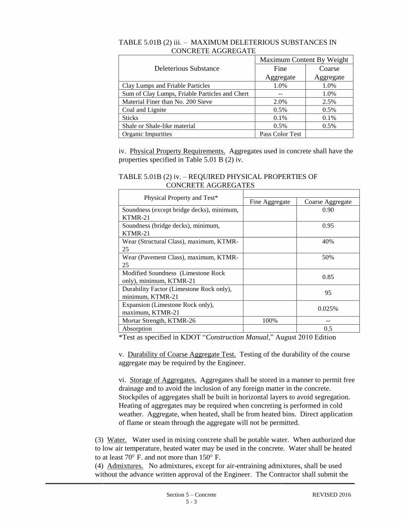
iii. Deleterious Substances. The maximum deleterious substance content in
aggregates used in concrete is shown in Table 5.01 B (2) iii. below.
Section 5 – Concrete REVISED 2016
5 - 3
TABLE 5.01B (2) iii. – MAXIMUM DELETERIOUS SUBSTANCES IN
CONCRETE AGGREGATE
Deleterious Substance
Maximum Content By Weight
Fine
Aggregate
Coarse
Aggregate Clay Lumps and Friable Particles 1.0% 1.0%
Sum of Clay Lumps, Friable Particles and Chert -- 1.0%
Material Finer than No. 200 Sieve 2.0% 2.5%
Coal and Lignite 0.5% 0.5%
Sticks 0.1% 0.1%
Shale or Shale-like material 0.5% 0.5%
Organic Impurities Pass Color Test
iv. Physical Property Requirements. Aggregates used in concrete shall have the
properties specified in Table 5.01 B (2) iv.
TABLE 5.01B (2) iv. – REQUIRED PHYSICAL PROPERTIES OF
CONCRETE AGGREGATES
Physical Property and Test*
Fine Aggregate Coarse Aggregate
Soundness (except bridge decks), minimum,
KTMR-21
0.90
Soundness (bridge decks), minimum,
KTMR-21
0.95
Wear (Structural Class), maximum, KTMR-
25
40%
Wear (Pavement Class), maximum, KTMR-
25
50%
Modified Soundness (Limestone Rock
only), minimum, KTMR-21
0.85
Durability Factor (Limestone Rock only),
minimum, KTMR-21
95
Expansion (Limestone Rock only),
maximum, KTMR-21
0.025%
Mortar Strength, KTMR-26 100% --
Absorption 0.5
*Test as specified in KDOT “Construction Manual,” August 2010 Edition
v. Durability of Coarse Aggregate Test. Testing of the durability of the course
aggregate may be required by the Engineer.
vi. Storage of Aggregates. Aggregates shall be stored in a manner to permit free
drainage and to avoid the inclusion of any foreign matter in the concrete.
Stockpiles of aggregates shall be built in horizontal layers to avoid segregation.
Heating of aggregates may be required when concreting is performed in cold
weather. Aggregate, when heated, shall be from heated bins. Direct application
of flame or steam through the aggregate will not be permitted.
(3) Water. Water used in mixing concrete shall be potable water. When authorized due
to low air temperature, heated water may be used in the concrete. Water shall be heated
to at least 70 F. and not more than 150 F.
(4) Admixtures. No admixtures, except for air-entraining admixtures, shall be used
without the advance written approval of the Engineer. The Contractor shall submit the

Section 5 – Concrete REVISED 2016
5 - 4
type of admixture for approval by the Engineer. The Contractor is solely responsible for
the appropriate use and effect of the admixture. The amount of admixture shall be
determined by the Contractor. No additional compensation will be allowed for
furnishing and incorporating the admixture into the work.
i. Air Entraining Agent. Air entraining agent shall conform to the requirements
of ASTM C260.
ii. Water Reducing Admixtures. Water reducers, which may include set
retarders, may be required when placing or finishing or when weather conditions
are unfavorable and would be improved by use of a water reducer.
iii. Plasticizers. Unless approved in advance by the Engineer, plasticizers are
not to be used. The maximum slump allowed with a plasticizer admixture is 8
inches. No water shall be added to the concrete mix after the addition of
plasticizer.
iv. Accelerating Admixtures. Under very special conditions, such as an
immediate need for opening a lane to traffic, concrete used in isolated pavement
areas may include a non-chloride accelerator when approved by the Engineer.
(5) Fiber Reinforcement. When specified in the Project Documents or approved by the
Engineer, fiber reinforcement shall be synthetic macro fibers that are monofilament, non-
fibrillating made of 100% virgin polyolefin. The fibers shall have a length between 1.38
and 2.00 and a length to diameter ratio of 75 to 90. The minimum tensile strength of the
fibers is 90 ksi. The application rates shall be based on the manufacturer’s
recommendations to provide a residual strength greater than 150 psi. Fiber
reinforcement shall be mixed into the concrete according to manufacturer’s
requirements.
(6) Curing Compound. A liquid membrane-forming curing compound shall be used for
all applications, unless otherwise specified by the Engineer. The compound shall
conform to the requirements for Type 2 - White Pigmented Compound as specified in
AASHTO M 148 and ASTM C 309.
C. Concrete Proportioning and Strength Requirements.
(1) Submittal of Mix Design. The Contractor shall furnish data to the Engineer on the
proposed mix design for each concrete mix. The mix design shall indicate the source of
the aggregates and cementitious materials. The test results from a trial batch or test
results from a previous project using the mix design shall be submitted to the Engineer
for review.
(2) Strength Requirements.
i. Structure Class. The minimum 28 day compressive strength of Structure
Class concrete shall be 4,000 pounds per square inch, unless otherwise specified
for individual projects.
ii. Pavement Class-A and Pavement Class-B. The minimum 28 day
compressive strength of Pavement Class Class-A and Pavement Class-B concrete

Section 5 – Concrete REVISED 2016
5 - 5
shall be 4,000 pounds per square inch. The minimum 28 day flexural strength
(Modulus of Rupture) shall be 600 pounds per square inch as determined by the
third point loading method, unless otherwise specified for individual projects.
iii. Commercial Grade. The minimum 28 day compressive strength for
Commercial Grade concrete shall be 2500 pounds per square inch.
(3) Minimum Cementitious Material Content. The minimum cementitious material
content per cubic yard of concrete for each class shall be as shown in the following
Table 5.01 C (3).
TABLE 5.01 C (3) – MINIMUM CEMENTITIOUS MATERIAL CONTENT OF
CONCRETE
CONCRETE CLASS MINIMUM CEMENTITIOUS MATERIAL CONTENT PER
CUBIC YARD OF CONCRETE
Structure Class 602 lbs. Type I/II Portland Cement (6.4 sacks)
Pavement Class-A
600 lbs. with minimum of 450 lbs of Type I/II Portland
Cement combined with Grade 100 or 120 Ground Granulated
Blast Furnace Slag at a maximum of 25% of the combined
total cementitious weight, or
600 lbs. with a minimum of 450 lbs. of Type I/II Portland
Cement combined with Class F Flyash at a maximum of 25%
of the combined total cementitious weight.
Pavement Class-B 600 lbs. Type I/II Portland Cement (6.4 sacks)
Commercial Grade 470 lbs. Type I/II Portland Cement (5.0 sacks)
(4) Water-to-Cement Ratio. The selected ratio of water to cementitious material by
weight in the mix must be low enough to ensure that durability, strength and wear
resistance requirements are satisfied. Maximum water-to-cementitious material ratios
for each concrete class shall be as shown in Table 5.01 C (4) below.
TABLE 5.01 C (4) – WATER TO CEMENTITIOUS MATERIAL RATIO
CONCRETE CLASS POUNDS OF WATER PER POUND OF
CEMENTITIOUS MATERIALS
Structure Class 0.49
Pavement Class-A and
Pavement Class-B
0.44
Commercial Grade per approved design
(5) Aggregate Proportioning. All mixes shall consist of at least two individual
aggregates – fine aggregate and coarse aggregate. Proportioning of materials will be
done on the basis of weight. Exact proportions of coarse and fine aggregates shall be
stated in the mix design.

Section 5 – Concrete REVISED 2016
5 - 6
Except where otherwise directed by the Engineer, the proportion of coarse aggregate to
total aggregate in Pavement Class-A and Pavement Class-B concrete shall be between 50
and 60%.
Structure Class concrete mixes shall be 50% coarse aggregate.
(6) Entrained Air. All concrete under these specifications, except Commercial Grade,
shall be air entrained, unless otherwise specified for individual projects. Air content for
Pavement Class-A, Pavement Class-B, and Structure Class concrete shall be 6.5% (±
1.5%) measured before and after placement of the concrete.
(7) Slump. The Contractor shall designate a slump for fresh concrete for each class that
is within the following ranges:
Structure Class: 1 inch - 3 inches
Pavement Class-A: 1 inch - 3 inches
Pavement Class-B: l inch - 3 inches
Commercial Grade: 3 inches - 5 inches
Fresh concrete delivered to the site shall slump the amount designated with the approved
mix design slump ±25% unless otherwise approved.
(8) Alkali Content. The sum of the acid soluble alkali content of portland cement plus
either 1/6 of the alkali content of the flyash, or 1/2 of the alkali content of the slag, shall
not exceed 5 lbs. per cubic yard.
D. Sampling and Testing.
(1) Parties Responsible for Testing. Sampling and testing of the materials used in the
concrete, including the fine and coarse aggregates, and cementitious materials, shall be
the responsibility of the Contractor. Tests shall be performed in accordance with the
requirements of the various ASTM and KDOT standards and tests referenced in
Subsections 5.02 B and 5.02 C. Test results from an ACI certified testing laboratory shall
be furnished to the Engineer with the mix design.
Sampling and testing of the fresh concrete will be the responsibility of the Owner for
Projects within the City Limits and as specified in the Project Documents for County
projects.
(2) Sampling Fresh Concrete. Samples of fresh concrete shall be obtained and handled
in accordance with ASTM C 172, “Sampling Fresh Concrete.”
(3) Consistency (Slump). Slump tests of fresh concrete shall be made in accordance
with ASTM C 143, “Slump of Portland Cement Concrete.”
(4) Air Content. The air content of fresh concrete shall be determined by the
volumetric method, ASTM C 173 or by the pressure method, ASTM C 231.
(5) Compressive Strength. During the progress of the work, compression tests will be
made at designated time intervals when directed by the Engineer. A test will consist of a

Section 5 – Concrete REVISED 2016
5 - 7
minimum of two compression cylinders. A set of cylinders will be made, at a minimum,
for each 150 cubic yards of concrete placed.
Compression test specimens will be made in accordance with the provisions of ASTM C
31. They will be laboratory cured cylinders to test the potential of the concrete that is
delivered. No field-cured cylinders will be made unless required by the Engineer.
No individual test shall fall more than 500 pounds per square inch below design strength.
The average of three consecutive tests shall equal or exceed design strength. If test
strengths fail to reach the required compressive strength, the Engineer will require the
Contractor to adjust the mix design. Concrete that fails to meet requirements may be
removed from the work or not accepted for payment at the Engineer's discretion.
Compression test strengths exceeding the required compressive strength will not be
considered as justification for increasing the water-cement ratio.
(6) Flexural Strength. Flexural strength tests may be required by the Engineer. A
minimum of two beams shall be cast per test. Test procedures shall be in accordance
with ASTM C31 and ASTM C78.
(7) Mortar Bar Expansion. Mortar bar expansion tests are required if the cementitious
combination contains less than 25% slag or fly ash. The Mortar bar expansion shall be a
maximum of 0.10% at 16 days when tested according to ASTM C1567.
E. Mixing, Delivery, and Placement.
(1) Mixing. All concrete shall be ready-mixed concrete complying with the provisions
of ASTM C94.
(2) Conveying. The normal method of transporting concrete shall be via ready-mix
truck.
(3) Delivery Tickets. A concrete delivery ticket shall be provided to the Engineer’s
Representative with each concrete load. The ticket shall contain the following
information: plant name, w/c ratio, time batched, batch weights, design slump, water
withheld (2 gallons per cubic yard maximum), dosage of all approved admixtures, and
number of cubic yards of concrete batched.
(4) Placing. Concrete shall be deposited as nearly as practicable in its final position.
Chutes used shall be such that the concrete slides in them and does not flow. Where a
vertical drop greater than 5 feet is necessary, placement shall be through tremie chutes or
similar devices to prevent segregation.
Concrete shall be placed before initial set has occurred, and in no event after it has
retained its water content for more than 90 minutes, regardless of whether or not
admixtures have been added. Unless otherwise specified, all concrete shall be deposited
upon clean, damp surfaces, free from running water, or upon properly consolidated fills,
but never upon soft mud or dry porous earth. No concrete shall be placed on frozen
subgrade.
Section 5 – Concrete REVISED 2016
5 - 8
Concrete shall be placed under water only with the permission of the Engineer. The
minimum cement content per cubic yard shall be increased by 10% at the Contractor’s
cost and the slump shall be increased to 6 inches. When depositing concrete in standing
water, the concrete shall be carefully placed in the space in which it is to remain in a
compact mass, by means of a tremie, bottom-dumping bucket or other approved method
that does not permit the concrete to fall without adequate protection. Concrete shall not
be disturbed after being deposited. Concrete shall be placed under water only in forms
that are reasonably watertight. Unless authorized by Engineer, water shall not be
pumped from inside forms while concrete is being deposited.
(5) Cold Weather. In cold weather, a concrete protection plan shall be submitted to the
Engineer for review and approval. This plan shall include any admixtures and the means
and methods for protecting the concrete from physical damage or reduced strength
caused by frost, freezing actions, or low temperatures during the cure period.
Concrete shall be mixed and placed only when the temperature is at least 35F. and
rising unless other arrangements have been approved by the Engineer.
When the air temperature is at or is expected to fall below 40ºF, the water and aggregates
should be uniformly heated before mixing to obtain a concrete mixture temperature of
not less than 50ºF and not more than 80ºF at point of placement. The concrete pavement
shall be maintained at a minimum temperature of 50ºF, as measured along the surface of
the concrete, for a minimum of 5 days after placing. A sufficient supply of approved
moisture barrier material, other than liquid curing compound, and suitable blanketing
material, such as straw, hay and burlap, shall be available if needed for all concrete
placed between November 1 and April 1. Frozen materials or materials containing ice
or snow shall not be used in the concrete. Calcium chloride, salt, or other materials
containing antifreeze agents or chemical accelerators, shall not be used in the mix unless
approved by the Engineer. If, during the curing period, the temperature of the concrete
falls below 32F, the concrete shall be removed and replaced at the Contractor’s
expense.
When structural concrete is to be placed in cold weather and the air temperature has been
below 35F for 24 hours or more, the reinforcing steel shall be placed and the forms set.
Forms and reinforcing shall then be heated to a minimum of 50F, using an enclosure
and space heaters, before concrete is placed.
When structural concrete is being placed and the ambient air temperature may be
expected to drop below 35F during the curing period, the Contractor shall provide
insulating blankets or other approved insulating materials and/or hosing and artificial
heat to maintain the concrete temperature between 50F and 80F as measured on the
surface of the concrete. The surface of the concrete shall be kept moist by use of an
approved moisture barrier such as wet burlap or polyethylene sheeting. The moisture
barrier shall be maintained in intimate contact with the concrete during the entire curing
period. After the completion of the required curing period, the Contractor shall remove
the curing and protection in such a manner that rapid cooling of the concrete will be
prevented. If, during the curing period, the temperature of the concrete falls below 32F,
the concrete shall be removed and replaced at the Contractor’s expense.
(6) Hot Weather. When concrete is being placed in warmer weather (ambient air
temperatures above 80F) the following shall apply:

Section 5 – Concrete REVISED 2016
5 - 9
i. Temperatures Below 80F. When the ambient air temperature at the time of
batching is expected to be below 80F, concrete must be in place within ninety
minutes after the water has been added.
ii. Temperatures Between 81F and 90F. When the ambient air temperature at
the time of batching is expected to be between 81F and 90F, concrete must be
in place within one hour after the water has been added unless an approved set-
retarding admixture is used.
iii. Temperatures Above 90F. When the ambient air temperature at the time of
batching is expected to rise above 90F, concrete must be in place within forty-
five minutes after the water has been added unless an approved set-retarding
admixture is used. In no case shall the concrete temperature exceed 90F at the
time of placement.
When concrete is being placed and the ambient air temperature may be expected
to rise above 90F, a specific hot weather protection plan shall be submitted to
the Engineer for review and approval. Depending on the severity of the weather,
the plan may include cooling of concrete mix to below 90F, scheduling work to
place and finish concrete during cool periods of the day, pre-wetting of forms
and subgrade, rapid placement of curing material, use of fog spray or other
methods recommended by ACI 305. Use of a retarder will be considered only in
the most severe conditions and then only if delay of placement poses a threat to
public welfare.
(7) Consolidation. Consolidation of concrete shall be accomplished with internal
mechanical vibration. Vibration shall be transmitted directly to the concrete and in no
case shall vibration be transmitted through the forms. The duration of vibration at any
location in the forms shall be held to the minimum necessary to produce thorough
compaction. Vibration shall be supplemented by forking or spading by hand adjacent to
the forms on exposed faces in order to secure smooth, dense and even surfaces. Concrete
shall be compacted and worked into all corners and angles of the forms and around
reinforcement and embedded fixtures in such a manner as to prevent segregation of the
coarse aggregate. Use of vibrators to move concrete within forms shall not be permitted.
Vibrators shall not be dragged horizontally through the concrete.
The use of flex shaft or high cycle vibrators is required on all concrete slabs except those
4 inches or less in thickness.
F. Curing.
(1) Curing Period. All newly placed concrete shall be cured immediately after finishing
for a minimum of 5 days, unless otherwise shown. Formed surfaces shall be cured if
forms are removed prior to 5 days after concrete placement.
(2) Application of Curing Compound. A liquid membrane-forming curing compound
shall be applied immediately after finishing and after the free water has left the surface
of the concrete. The Contractor shall apply liquid membrane-forming curing compound
in one application at a uniform rate of at least one gallon per 150 square feet of surface,

Section 5 – Concrete REVISED 2016
5 - 10
unless otherwise specified by the Engineer. Thinning the white membrane compound
will not be permitted.
The treated surface shall be protected by the Contractor from injury of any sort for a
period of at least 5 days. Any damage shall be repaired immediately. Immediately after
forms are removed, the area formerly covered by forms, including the sides of slabs,
shall be coated with curing compound at the rate specified above.
(3) Other Curing Materials. Burlap, white polyethylene sheeting, cotton mats,
insulating blankets and other materials may be used to aid in curing as approved or
specified by the Engineer.
G. Measurement and Payment. All materials, labor, tools, equipment and incidentals necessary
for proportioning, testing, sampling, mixing, delivering, placing, consolidating and curing
concrete shall not be paid for directly but shall be subsidiary to the item of work for which it is
performed.
5.02 FORMS
A. Materials.
(1) Forms. Construction forms shall be sufficiently strong to support all loading without
deflection either horizontally or vertically. Forms shall be composed of wood, metal, or
other materials which have been approved in advance by the Engineer. Form surfaces
shall be smooth and free from irregularities, dents, sags, or holes when used for
permanently exposed faces. Aluminum forms shall not be used.
(2) Oil. Oil applied to forms shall be any commercially available non-staining mineral
oil or paraffin oil.
(3) Form Ties. Form ties shall be either epoxy coated steel or non-metallic.
B. Construction Requirements.
(1) General. Forms shall be built true to line and grade, mortar tight and sufficiently
rigid to prevent displacement or sagging between supports. Forms shall be staked or
braced sufficiently so that they will not be knocked out of line by any of the normal
operations of placing and finishing the concrete. Construction of forms for the lifts of
vertical walls shall be such as to make all parts of the walls easily accessible for the
placement, spading and consolidation of the concrete as specified herein.
Curved concrete forms shall be used for construction of curved concrete unless the
curve’s radius is greater than 60 feet.
Joints in the forms shall be locked rigidly in true alignment to prevent play or movement.
All metal, including form ties, shall have at least 2 inches clearance from the face of the
concrete unless otherwise specified. Wire ties will not be permitted where the concrete
surface will be exposed to weathering and discoloration will be objectionable. Form ties
shall be removed to a depth of ½ inch below the concrete surface. All forms shall be so

Section 5 – Concrete REVISED 2016
5 - 11
constructed that they can be removed without hammering or prying against the concrete.
Unless otherwise indicated, suitable molding shall be placed to bevel or round all
exposed edges and expansion joints.
(2) Coating of Forms. Forms, other than those having non-absorptive form lining for
exposed surfaces, shall be coated with non-staining oil which shall be applied shortly
before the concrete is placed. Forms for unexposed surfaces may be thoroughly wetted
with water in lieu of oil, immediately before the placing of concrete, except that in
freezing weather oil shall be used. Form oil shall not be applied in a manner that will
cause it to come in contact with reinforcing steel.
(3) Removal of Forms. The removal of forms shall be accomplished in such a manner
as will prevent injury to the concrete. Forms shall not be removed before the expiration
of the minimum time indicated below, except when specifically authorized by the
Engineer. During cold weather the time limits may be increased at the discretion of the
Engineer depending upon the amount of protection provided. Permission to remove
forms shall not constitute authority to backfill structures. Backfill shall proceed only
upon approval of the Engineer and shall be based on concrete attaining 75% of design
strength.
Pavement and Slabs -------------------- 12 hours*
Walls and Vertical Faces -------------- 2 days*
Columns ---------------------------------- 7 days
Unsupported Beams & Slabs:
Spans less than 10' ---------------------- 4 days*
Spans from 10' to 20' ------------------- 7 days
Spans over 20' --------------------------- 10 days
*Curing of surfaces exposed by form removal is required.
(4) Resetting or Replacing Forms. Any forms disturbed, lost, or damaged for any
reason including, but not limited to, high water, vandalism and theft, shall be reset or
replaced to the satisfaction of the Engineer at the Contractor’s sole expense.
C. Measurement and Payment. All materials, labor, tools, equipment and incidentals necessary
for the construction of forms for concrete shall not be measured or paid for directly but shall be
subsidiary to the item of work for which the forms are constructed.
5.03 REINFORCING STEEL
A. Materials. All reinforcing steel shall be free from mud, oil, paint, grease or other organic
material that may adversely affect or reduce bond with the concrete. Shop drawings, bar lists,
and splicing details shall be furnished to the Engineer by the Contractor when specified in the
Project Documents.
(1) Reinforcing Bars. Reinforcing bars for concrete shall conform to the requirements
of ASTM A615, Grade 40 or Grade 60 as specified in the Project Documents.
(2) Welded Steel Wire Fabric. Concrete reinforcing mesh shall be steel welded wire
conforming to the requirements of ASTM A1064.
Section 5 – Concrete REVISED 2016
5 - 12
(3) Tie bars. Pavement tie bars shall be Grade 40 deformed steel bars, which conform
to the requirements for reinforcing bars.
(4) Dowels. Steel Dowel bars shall be plain round steel bars conforming to the
requirements of ASTM A615 (40 KSI).
(5) Expansion Joint Assemblies. Expansion joint assemblies shall meet the
requirements of ASTM A615, Grade 40 and the requirements set forth in the Project
Documents.
(6) Supports and Spacers. Reference is made to the latest edition of the CRSI “Manual
of Standard Practice” for recommended industry practices concerning reinforcing steel
supports and spacers. Use only wire type bar supports. Plastic chairs are not acceptable.
Rocks, bricks or other non-steel supports are not acceptable.
B. Construction Requirements. The Contractor shall furnish and install all reinforcement,
including bars, fabric, and structural shapes as indicated in the Project Documents or otherwise
required by standard concrete construction practice.
(1) Placing Reinforcement. All reinforcement shall be accurately placed, with clear
spacing between main reinforcement and concrete surfaces as shown in the Project
Documents or as may be directed by the Engineer.
The minimum clear distance between parallel bars shall be 1½ times the nominal
diameter of the bar, 1½ times the maximum size of the coarse aggregate, or 1½ inches,
whichever is greater.
Prior to placement of concrete, reinforcement shall be in place and reviewed by the
Engineer. Reinforcing steel shall be supported by spacers, hangers, or other reinforcing
steel and secured in place with wire ties or suitable clips. Embedments shall be secured
with templates.
Positioning tolerances for centerline of reinforcing shall be + 1/4 inch for members less
than 12" thick and + 3/8 inch for larger members. Locations of laps and bends shall be
true to + 2 inches. Location of ends of reinforcing shall be true to +1/2 inch. Location
of Embedments shall be true to + 1/4 inch.
(2) Splicing. Splices shall be installed in accordance with the Project Documents and
Shop Drawings. Where splices in reinforcement, in addition to those indicated, are
necessary and approved by the Engineer, there shall be sufficient lap to transfer the stress
by bond, as may be directed. Bars shall be lapped not less than 30 diameters unless
otherwise shown, and splices shall be staggered. Welding or tack welding of
reinforcement shall not be permitted.
(3) Supports. All reinforcement shall be secured in place, true to the lines and grades
indicated, by the use of metal or concrete supports, spacers, or ties. Such supports shall
be of sufficient strength to maintain the reinforcement in place throughout the concreting
operation, and shall be used in such a manner that they will not be exposed on the face or
in any way discolor or be noticeable in the surface of the finished concrete.

Section 5 – Concrete REVISED 2016
5 - 13
A sufficient number of metal bar supports or pins shall be used to hold all bars in proper
position according to the Project Documents.
(4) Resetting or Replacing Reinforcing Steel. Any reinforcing steel disturbed, lost, or
damaged for any reason including, but not limited to, high water, vandalism and theft,
shall be reset or replaced to the satisfaction of the Engineer at the Contractor’s sole
expense.
C. Bid Items, Measurement and Payment.
(1) Bid Items:
REINFORCING STEEL, GRADE 40 Unit: Lbs. (nearest 10 lbs.)
REINFORCING STEEL, GRADE 60 Unit: Lbs. (nearest 10 lbs.)
(2) Measurement. When listed as a bid item in the Project Documents “Reinforcing
Steel, Grade 40” and/or “Reinforcing Steel, Grade 60”, shall be measured by the weight
of the reinforcing steel including reinforcing bars, welded wire fabric, dowels, tie bars
and any other steel reinforcing. The weight shall be determined in pounds based upon
the theoretical length and unit weight of the reinforcing steel as shown in the Project
Documents plus or minus any additions or reductions of reinforcing steel installed as
requested or approved by the Engineer. The weight of the steel shall be rounded to the
nearest 10 pounds for each application for payment.
(3) Payment. When listed as a bid item in the Project Documents, Reinforcing Steel,
Grade 40 and Reinforcing Steel, Grade 60 measured as specified above, shall be paid for
at their respective Contract unit prices, such payments shall be full compensation for the
furnishing, fabrication, placing, splicing, and supporting of the reinforcing steel as
specified, and for all materials, equipment, tools, labor, and incidentals necessary to
complete the work.
5.04 CONCRETE STRUCTURES
A. Materials.
(1) Concrete. Concrete used in both precast and cast-in-place concrete structures shall
be Structure Class Concrete meeting all the requirements specified in Subsection 5.01.
(2) Forms. Forms used for cast-in-place concrete structures shall meet all the
requirements specified in Subsection 5.02.
(3) Reinforcing Steel. Reinforcing steel used in both precast and cast-in-place concrete
structures shall meet all the requirements specified in Subsection 5.03.
B. Construction Requirements.
(1) Excavation, Subgrade and Foundation Preparation. The excavation, subgrade and
foundation preparation for concrete structures shall be completed as specified in Section
2, Excavation, Backfill and Compaction. The Contractor shall not place forms or
reinforcing prior to the Engineer’s approval of the subgrade. Structure Excavation shall

Section 5 – Concrete REVISED 2016
5 - 14
not be measured or paid for directly, but shall be subsidiary to the structure for which the
excavation is performed, including retaining walls and combined sidewalk and retaining
walls.
(2) Forms. Forms shall be set as specified in Subsection 5.02.
(3) Reinforcement. Reinforcing steel shall be set as specified in the Project Documents
and Subsection 5.03.
(4) Placing Concrete for Structures.
i. Walls and Columns. Walls and columns supporting concrete beams, concrete
joists, or concrete slabs shall be poured to the underside of such beams, joists, or
slabs at least 8 hours before the placement of the superimposed work, or as
directed by the Engineer.
ii. Vibration. Concrete shall be consolidated with the aid of mechanical
vibrating equipment. Vibration shall be transmitted directly to the concrete and
in no case shall vibration be transmitted through the forms. The duration of
vibration at any location in the forms shall be held to the minimum necessary to
produce thorough consolidation. Vibration shall be supplemented by forking or
spading by hand adjacent to the forms on exposed faces in order to secure
smooth, dense and even surfaces. Use of vibrators to move concrete within
forms shall not be permitted. Vibrators shall not be dragged horizontally
through the concrete.
(5) Finishing.
i. Unexposed Surfaces. Concrete for which no other finish is specified shall
have fins and rough edges removed.
ii. Surfaces Exposed to Sight or Weather. All unsightly ridges or lips shall be
removed and local bulging shall be remedied by tooling and rubbing. All holes
left by the removal of rods and all voids, unless otherwise directed, shall be
reamed and filled with mortar as directed.
iii. Top Surfaces of Walls. Walls shall be brought to the proper elevations as
shown on the Drawings and top surfaces finished with a wood float to a true and
regular surface. The application of sand or cement drier will not be permitted.
No water shall be present when the surfaces are finished.
iv. Floors. Concrete floors shall be finished by the proper use of the bull float.
The use of the jitterbug will not be permitted. Troweling shall not be done until
concrete has hardened sufficiently to prevent excess fine material being worked
to the surface. An approved clear hardener/anti-dusting compound shall be
applied after curing. Slabs shall be sloped as shown on the Drawings.
v. Cavities. The cavities on all exposed surfaces shall be filled with portland
cement mortar. The resulting surface shall be smooth and sound, and shall
match the adjacent surfaces in color and texture. Cavities on unexposed surfaces

Section 5 – Concrete REVISED 2016
5 - 15
shall be filled with an approved material, including roof cement or portland
cement at the Contractor's option.
(6) Tolerances. All members except inverts and footings shall be no more than 1/4 inch
thinner nor 1/2 inch wider than shown in the Project Documents. Thickness of footings
shall be no more than 5% thinner than shown in the Project Documents. Formed
surfaces shall be within the following tolerances:
i. Vertical Lines. Vertical lines, edges and surfaces shall be plumb to 1/4 inch
in 10 feet, and 1/2 inch in the entire length.
ii. Horizontal Lines. Horizontal lines and edges shall be level to within 1/4
inch in 20 feet, and 1/2 inch in the entire length.
iii. Linear Elements. Linear elements shall be at the position shown on the
Drawings to within 1/2 inch. Embedments shall be at position shown on the
Drawings to within 1/4 inch.
(7) Special Requirements for Combined Sidewalk and Retaining Walls. Where
combined sidewalks and retaining walls are constructed without rustication of the face of
the wall, the wall forms shall have ¾” chamfer strips (front and back) aligning with the
joints in the sidewalk member to make certain the vertical joints of the wall align with
the sidewalk joints.
C. Bid Items, Measurement and Payment.
(1) Bid Items:
STRUCTURE CLASS CONCRETE ( * ) Unit: Cubic Yard (Nearest 0.1 C.Y.)
COMBINED SIDEWALK AND RETAINING Unit: Liner Foot (Nearest 0.1 L.F.)
WALL
( * ) – Type of Structure, e.g. RCB, Ret-Wall, Bridge, etc.
(2) Measurement. When concrete structures are quantified in the Project Documents
under the item “Structure Class Concrete (*)”, the concrete shall be measured by the
volume of the concrete in the structure. No deduction shall be made for the volume of
reinforcing steel encapsulated by concrete. The volume shall be the computed
theoretical volume of the solid portion of the structure plus or minus any additions or
reductions to the concrete construction requested or approved by the Engineer. The
volume shall be computed and rounded to the nearest 0.1 cubic yard for each application
for payment.
“Combined Sidewalk and Retaining Wall” shall be measured by the linear foot along the
base of the wall to the nearest 0.1 linear foot..
(3) Payment. Where the Project Documents quantify construction of a concrete
structure under the Pay Item “Structure Class Concrete” payment for completed and
accepted work, measured as provided above, shall be made at the corresponding Contract
Unit Price. Such payment shall be full compensation for the furnishing, mixing,
transporting, forming, placing, supporting, consolidating, and curing necessary for the

Section 5 – Concrete REVISED 2016
5 - 16
construction of the concrete structure as specified, and for all materials, equipment,
tools, labor, and incidentals necessary to complete the work.
Completed and accepted “Combined Sidewalk and Retaining Wall”, measured as
provided above, shall be paid for at the corresponding Contract Unit Price. Such
payment shall be full compensation for the furnishing, mixing, transporting, excavating,
backfilling, forming, reinforcement placing, supporting, consolidating, and curing
necessary for the construction of the retaining wall and adjacent sidewalk, and for all
reinforcing steel, concrete, materials, equipment, tools, labor, and incidentals necessary
to complete the work.
5.05 CONCRETE PAVEMENT, VALLEY GUTTERS, DRIVEWAYS, CURBS AND GUTTERS,
AND MEDIAN NOSES
A. Scope. This Subsection 5.05 applies to all concrete pavement, slabs, truck aprons, valley
gutters, driveways, parking lots or other concrete subjected to vehicular traffic. This subsection
also applies to all types of concrete curb, all types of combined curb and gutter, and concrete
median noses.
B. Materials.
(1) Concrete. Concrete used in pavements subjected to vehicular traffic, median noses,
and all types of curb and curb and gutter shall be Pavement Class-A concrete as specified
in Subsection 5.01.
(2) Forms. Forms shall be as specified in Subsection 5.02.
(3) Reinforcing Steel. Reinforcing steel, dowel bars, dowel baskets, welded wire fabric,
and tie bars shall be as specified in Subsection 5.03.
(4) Expansion Joint Material. Expansion joint filler material shall be non-extruding and
resilient filler which conforms to the requirements of AASHTO M 213 and ASTM D
1751-04. Unless indicated otherwise in the Project Documents, expansion joint filler
shall be ½ inch thick and extend the entire thickness of the concrete slab.
i. Basis of Acceptance. Expansion joint material shall be accepted based upon
the Engineer’s receipt of a manufacturer’s certification or catalog cut indicating
the material meets the requirements specified and upon the Engineer’s visual
inspection of the material in place.
(5) Joint Sealants. Any joint sealants used shall be approved by the Engineer prior to
installation. Joint sealants shall be manufactured to provide for filling the entire joint
depth without the use of backer rod. Backer rod is not acceptable.
i. Hot Type Joint Sealants. Hot type joint sealants shall be specifically
manufactured for use in sealing joints in portland cement pavements and shall
meet all applicable requirements of ASTM D3406. The contractor shall furnish
to the Engineer a certification or catalog cut that the sealant used meets these
requirements.

Section 5 – Concrete REVISED 2016
5 - 17
ii. Silicone Joint Sealant. The silicon joint sealant shall be either Type I (Non
Self-Leveling) or Type II (Self-Leveling). Joint sealants shall be a one-part cold
applied silicone formulation that is self-priming to and compatible with portland
cement concrete. Acetic acid cure sealants are not acceptable. Type II sealants
shall be self-leveling within the joint and shall provide a satisfactory surface
configuration without tooling. The silicone sealants shall meet all requirements
of ASTM D5893 and shall also comply with the following applicable test
requirements:
Property Type I Type II
(1) Skin development time, minutes 120 max. 120 max.
(2) Cure-through pass pass
(3) Extrusion rate, grams/minute 90/250 200/600
(4) Non-volatile content, % 90 min. 90 min.
(5) Bond to concrete, @ 0 F.,
5 cycles, 100% extension pass pass
(6) Compression set pass pass
(7) Elongation, % 600 min. 1000 min.
iii. Basis of Acceptance. Joint sealants will be accepted based upon the
Engineer’s receipt of a manufacturer’s certification that the material supplied
meets the requirements specified, and upon the performance of the material in
the field.
C. Construction Requirements for Concrete Pavement, Driveways, Median Nose, Curb, and
Combined Curb and Gutter.
(1) General. Construction of Concrete Pavement, Driveways, Median Noses, Curb, and
Combined Curb and Gutter shall meet the requirements for Pavement Class-A concrete
set forth in Subsection 5.01 and in this Subsection 5.05 C.
(2) Paving Equipment. All uniform sections and full lanes of pavement 75 lineal feet or
greater in length shall be paved with a self-propelled slipform or bridge deck paver. This
machine shall be designed specifically for paving operations and shall be capable of
producing an adequately consolidated concrete surface, true to grade, free of large
open-textured areas and without excessive flushing of the mortar. It shall be accurately
adjustable to conform to the plane of the pavement surface. The pavement equipment
shall be approved by the Engineer prior to submittal of bids for all trafficway projects.
Commercially made vibratory screeds and roller screeds may be used only on irregular
sections of pavement if approved by the Engineer. Screeds must be of the heavy-duty
type, have mechanical propelling mechanism, be adjustable as to length, and be
adjustable as to crown or valley.
Air compressors used for cleaning joints shall be equipped with suitable traps capable of
removing all surplus water and oil in the compressed air.
(3) Subgrade Preparation and Treatment. Subgrade preparation and treatment shall be
as specified in Sections 3.10 and 3.11. The Contractor shall receive the Engineer’s
approval of the subgrade prior to placing forms, placing reinforcement or pouring
pavement or curbs. Aggregate Base - Type AB-3 may be used under driveways within

Section 5 – Concrete REVISED 2016
5 - 18
the public right-of-way for the purpose of making final adjustment to dirt subgrade where
necessary to insure proper final grade and thickness. Sand is not allowed as a fine
grading material. Maximum allowable thickness of compacted Aggregate Base - Type
AB-3 shall be 6 inches unless approved otherwise by the Engineer.
(4) Forms. Forms used for fixed form concrete paving shall be as specified in
Subsection 5.02.
(5) Reinforcement. Reinforcing steel, steel dowel bars, tie bars, and wire fabric shall be
installed at the locations shown in the Project Documents. Reinforcement shall be
prevented from shifting due to normal finishing operations and shall be installed as
specified in Subsection 5.03.
(6) Manholes and Valve Castings. Manholes and valve castings located in a traffic lane
shall be adjusted to meet the grade and slope of the adjacent pavement surface in the
manner, and within the tolerances, specified in Subsection 6.07 B. (8).
(7) Placing of Concrete. The Contractor shall place concrete only after the Engineer has
approved the subgrade, forms and reinforcement. The concrete shall be deposited on the
subgrade for the full width between forms and in a manner that will prevent segregation
and which will require as little rehandling as possible The amount of material so
deposited shall be in excess of the amount required. Any additional spreading necessary
shall be done with hand shovels. Concrete shall not be placed on frozen or muddy
subgrade.
If a slipform paver is used, no tolerance will be allowed for edge sloughing. If edge
sloughing occurs during paving operations, these operations shall cease until adjustments
in the paver or concrete are made. The Contractor shall verify during paving operations
that the edge of the pavement is a true plane surface.
(8) Consolidation. After placement in its approximate final position, the concrete shall
be consolidated by means of spud vibrators inserted into the concrete. This operation
may be performed by hand or may be performed by vibrators attached to an approved
machine in a spreading and strike-off operation.
i. Curbs and Gutter. Consolidation of the concrete for curbs and gutter shall be
accomplished with internal mechanical vibration. Vibration shall be transmitted
directly to the concrete and in no case shall vibration be transmitted through the
forms. The duration of vibration at any location in the forms shall be held to the
minimum necessary to produce thorough compaction. Vibration shall be
supplemented by forking or spading by hand adjacent to the forms on exposed
faces in order to secure smooth, dense and even surfaces.
(9) Finishing Pavement. After the concrete is spread it shall be struck off and further
consolidated and screeded with an approved finishing machine or machines. The
finishing machine shall be moved ahead at an approximately uniform rate. It shall have a
vibration unit in the screed that shall be stopped when the machine is not moving
forward. A slight excess of concrete shall be kept ahead of the screed at all times.
The use of a concrete finishing agent must be approved by the Engineer.

Section 5 – Concrete REVISED 2016
5 - 19
Hand finishing operations may be used for narrow widths and irregular areas where the
use of an approved finishing machine is impractical. Hand finished concrete shall be
thoroughly consolidated with hand spud vibrators. Following hand strikeoff, the
concrete shall be in a condition equal to that produced by an approved finishing machine.
There shall be no change in slump in hand finished areas.
(10) Straightedge Floating Pavement. After the final pass of the finishing machine, the
entire surface shall be floated with straightedges not less than 10 feet in length. The
straightedges shall be operated parallel to the pavement centerline starting at the center
and progressing toward the forms. Advance along the road shall be in successive stages
of not more than half the length of the straightedges. The edges of the pavement will be
checked transversely by straight edge at close enough intervals to assure a plane surface
at the pavement edge or form line. All laitance, surplus water and inert material shall be
removed from the surface. All high places shall be worked down and all low places
filled by combined operations of flats and straightedges until no irregularities exist. The
proper crown of the pavement shall be maintained throughout the operations.
(11) Texturing Pavement. As soon as all excess moisture has disappeared and while the
concrete is still plastic enough to make a granular surface possible, a drag shall be used
which shall consist of a seamless strip of damp burlap or cotton fabric which shall
produce a uniform surface of gritty texture after dragging it longitudinally along the full
width of pavement. The drag shall be maintained in such condition that the resultant
surface is of uniform appearance and reasonably free from grooves over 1/16 inch deep.
Drags shall be maintained clean and free from encrusted mortar. Drags that cannot be
cleaned shall be discarded and new drags substituted.
(12) Finishing and Texturing Median Nose, Curbs and Gutter. Exposed surfaces shall
be shaped to the section shown in Standard Drawing DT-003 by using either a slip form
curb machine or steel tools and trowels and then brushed lightly. Brushing shall be
parallel to the roadway centerline. The cross section of the finished shape of the curb
and gutter section shall not be more than ½" deviated from the standard dimensions
shown on DT-003. If deviations are more than ½", then curb and gutter sections must be
removed and replaced at the Contractor’s expense.
All exposed edges and joint edges shall be rounded with an edging tool having a radius
of 3/8 inch. Moisture shall not be applied to the surface of the fresh concrete unless
approved by the Engineer.
(13) Curing. Curing shall be as specified in Subsection 5.01 F.
(14) Joints. Joints shall be constructed in accordance with the details shown in the
Project Documents and these specifications with the best of workmanship. All joints in
roadway pavement and alleys shall be formed by sawing. Joints in driveways, parking
areas, curbs, and combined curbs and gutters may be formed by either tooling or sawing.
All joints formed by sawing shall be pressure washed, sand blasted, blown clean and
sealed with an approved joint sealant compound. Failure to construct the joints in the
best possible manner will be cause for suspension of work until the cause of the
defective work is remedied.

Section 5 – Concrete REVISED 2016
5 - 20
The length of concrete panels shall not exceed 1.5 times the width. Panels shall be square
or rectangular wherever possible. Interior angles less than 60 degrees at the corners of
panels shall be avoided.
i. Types and Locations of Joints.
(1) Longitudinal Joints. Longitudinal joints shall be constructed as
shown in the Project Documents. Approved guide lines or devices shall
be furnished to insure cutting the longitudinal joint on the true line as
shown in the Project Drawings.
(2) Expansion Joints. Expansion joints shall be installed where the new
pavement butts against rigid objects, at all intersections between
sidewalks and driveways, between driveways and pavement curb, and at
all other locations indicated in the Project Documents or determined by
the Engineer. Expansion joints shall be formed with ½ inch
prefabricated non-extruding filler and shall extend the full depth of the
slab. All expansion joints shall be sealed with approved joint sealant.
(3) Welded Expansion Joint Assemblies. When specified in the Project
Documents, expansion joints with welded expansion joint assemblies
and expansion joint filler shall be installed in continuous lengths of
pavement. Expansion joint assemblies shall be installed at the locations
and in the manner specified in the Project Documents.
(4) Contraction Joints. Contraction joints shall be at the spacing shown
in the Project Documents. The spacing of contraction joints in feet shall
generally not exceed two times the pavement thickness in inches, but
shall in no case exceed 15 feet unless approved in advance by the
Engineer.
(5) Construction Joints. A butt construction joint, as shown in the
Project Documents, shall be made perpendicular to the centerline of the
pavement at the close of each day's work, and also when the process of
depositing concrete is stopped for a length of time such that, in the
opinion of the Engineer, the concrete will have taken its initial set.
Smooth Dowel bars shall be spaced along the joint as shown in the
Project Documents. No construction joint shall be placed within 10 feet
of an expansion joint or another construction joint.
ii. Joints in Curbs and Gutters, Driveways, and Parking Areas. Joints shall be
constructed in curbs and gutters, driveways and parking areas at the locations or
spacings shown in the Project Documents and may be formed by either tooling
or sawing. Where curb and gutter sections are adjacent to concrete pavement
sections, the joints shall match those in the pavement. Spacing shall not exceed
15 feet.
Tooled joints in curbs and gutters shall be formed by taking an approved tool,
such as a margin trowel, at the joint location and separating the aggregate in the
concrete through the entire curb section from the curb down its face and along
the gutter to a depth of at least 4 inches below the surface. A 1/4 inch groove 1

Section 5 – Concrete REVISED 2016
5 - 21
inch deep is then made at the joint location while the concrete is still plastic
enough to be worked but hard enough that it will not slump after grooving.
Tooled joints in slabs shall be formed by making a ¼ inch groove 25% of the
depth of the slab while the concrete is still plastic enough to be worked but hard
enough that it will not slump after grooving.
Joints formed by "tooling" do not need to be sealed with joint compound. All
joints formed by sawing shall be pressure washed, sand blasted, blown clean
and sealed with an approved joint sealant compound.
A butt construction joint shall be made at the close of each day’s work or when
the work is stopped long enough so that the previously placed concrete would
have taken its initial set. This joint shall extend completely through the slab and
be perpendicular to the finished surface.
iii. Sawing of Joints. All joints to be sawed shall be wet sawed and constructed
as shown in the Project Documents. The Contractor shall obtain a Noise Permit
if sawing of pavement is anticipated to be necessary between 10 PM and 7 AM
within the City of Topeka.
Sawing of joints shall be constructed in two stages as follows:
(1) First Stage. The first saw-cut shall be a relief cut approximately 1/8
inch wide and to a minimum depth of 1/3 the thickness of the slab.
Joints shall be sawed as soon as concrete has hardened sufficiently to
prevent excessive tearing and raveling and before conditions induce
uncontrolled cracks, regardless of the time or weather. The Contractor is
responsible for sawing at the appropriate time and making sure that any
equipment used does not damage the new pavement. Suitable guide
lines or devices shall be used to insure the joint is cut straight and has
the correct geometrics in relation to centerline. Curing membrane
damaged during sawing operation shall be repaired by the Contractor as
directed by the Engineer.
(2) Second Stage. Widening of the relief joints to full width (3/8”
maximum) shall not be performed until the concrete is at least 48 hours
old and shall be delayed longer when the sawing causes raveling of the
concrete. If second stage sawing is performed prior to completion of the
curing period, the Contractor shall maintain the cure by use of curing
tarps, plastic devices, or other approved materials. Curing membrane
damaged during the sawing operation shall be repaired by the Contractor
as directed by the Engineer. The second stage cut shall be exactly
centered over the relief cut and sawed 1-1/4”deep or as otherwise
specified in the Project Documents.
Should any spalling of the sawed edges occur which would detrimentally affect
the joint seal; it shall be patched with an approved epoxy patching compound
and allowed to harden prior to installation of the joint material. Each patch shall
be true to the intended neat lines of the finished cut joint.
Section 5 – Concrete REVISED 2016
5 - 22
Any transverse joint requiring hand finishing and edging shall be edged with a
tool having a radius of 1/8 inch unless otherwise directed by the Engineer. The
horizontal surface of the edger should not indent the surface of the pavement.
iv. Cleaning Freshly Cut Sawed Joints. Immediately after sawing the joint, the
resulting slurry shall be completely removed from the joint and the immediate
area by flushing with a jet of water under pressure, and by the use of other tools
as necessary.
v. Cleaning Joints. Just prior to sealant being applied, a final cleaning of the
joint shall be made by sandblasting the joint, followed by an air blast to clean
incompressibles from the joint. If one sandblaster nozzle is used, the joint shall
be cleaned once in each direction, concentrating on one joint face at a time. If a
two nozzle arrangement is used, the nozzles shall be aimed so each nozzle
concentrates its blast on one joint face.
Air compressors used for cleaning joints shall be equipped with suitable traps
capable of removing all surplus water and oil in the compressed air. This
compressed air will be checked daily by the Engineer for contamination. When
contaminated air is found to exist, work shall not resume until suitable
adjustments are made and the air stream is found to be free of such
contaminants.
vi. Sealing Joints. All sawed joints shall be sealed with an approved sealant.
The location and configuration of the joint sealant shall be as shown in the
Project Documents. Joints must be sealed prior to opening to traffic. The
Contractor shall provide a manufacturer's technical representative at the
beginning of the joint sealing operation to make available technical expertise in
proper joint preparation and cleaning; and application of the sealant in strict
compliance with manufacturer's recommendations and these Specifications. The
manufacturer’s representative shall ensure that both the Inspector and Contractor
are familiar with the proper procedures. The Engineer may waive this
requirement for Contractors that are experienced in installing the type and brand
of material being used.
(1) Curing and Seasonal Limitations. Joints shall not be sealed until
they are thoroughly clean and dry and the pavement is at least five days
old unless otherwise stipulated in the manufacturer's publications and
approved by the Engineer. Sealant shall not be applied to wet or damp
concrete or installed during inclement weather. Joint sealant application
will not be permitted when the ambient air temperature is less than 40F
or as specified in the manufacturer's publications.
(2) Filling Joints. The joint sealer, silicone or hot type, shall be applied
by an approved mechanical device from inside the joint in such a manner
that causes it to wet the joint surfaces. The sealer shall be placed in
reasonably close conformity with dimensions shown in the Project
Documents. Any unreasonable deviation will be cause for rejection of
the joint until satisfactory corrective measures are taken.

Section 5 – Concrete REVISED 2016
5 - 23
The Type I silicone sealant is not self leveling and will not position
properly in the joint under its own weight; therefore, the sealant surface
shall be tooled using the appropriate tool to produce a slightly concave
surface approximately 1/4 inch below the pavement surface as shown in
Standard Drawing DT-002. Tooling shall be accomplished before a skin
forms on the surface. The use of soap or oil as a tooling aid will not be
permitted. Any failure of the joint material in either adhesion or
cohesion will be cause for rejection, and the joint shall be repaired to the
Engineer's satisfaction at the Contractor's expense. Hot type joint
sealant shall fill the joint to a point level with the pavement surface and
shall be applied with a pressure applicator.
(3) Cleaning Pavement. After a joint has been sealed, all surplus joint
sealer on the pavement or structure surfaces shall be promptly removed.
(4) Traffic. Traffic shall not be permitted over sealed joints until the
sealer is tack free, or until debris from traffic does not imbed into the
sealant.
(15) Pavement Protection and Weather Limitations. Fresh concrete shall be adequately
protected from heavy rains and mechanical injury including vandalism. The weather
limitations set forth in Subsections 5.01 E (5) and (6) shall apply.
(16) Opening to Traffic. New concrete pavement shall not be opened to vehicular
traffic until the strength requirements set forth in the following Table 5.05 C (16) are
satisfied.
Table 5.05 C (16) - Strength Requirements for Opening Pavement to Traffic
Slab Thickness Minimum Requirements for Opening to Traffic
Less than 7.0" 5 Days Cure Time and 3,500 psi Compressive Strength*
7.0" or thicker 5 Days Cure Time and 3,000 psi Compressive Strength*
Any thickness of High
Early Strength Concrete
24 Hours Cure Time and 3000 psi Compressive Strength*
*Compressive Strength as indicated by cylinder breaks.
D. Basis Of Acceptance. Completed Concrete Pavement, Valley Gutters, Driveways, Curbs and
Combined Curb and Gutter shall be accepted based upon strength, surface trueness, surface
smoothness, thickness, and surface condition.
(1) Strength. Completed Concrete Pavement, Valley Gutters, Driveways, Curbs and
Combined Curb and Gutter shall be accepted for strength based upon the requirements of
subsection 5.01 C (2) and test methods set forth in Subsection 5.01 D (5) and (6). At the
Engineer’s discretion, concrete that fails to meet these requirements shall be either
removed and replaced with suitable concrete at the Contractors expense, or may remain
in place without payment for such item.
(2) Surface Trueness. The pavement surface and edges shall be true to the lines and
grades shown in the Project Documents. The pavement cross slope shall be maintained.

Section 5 – Concrete REVISED 2016
5 - 24
The cross section of the finished shape of the curb and gutter section shall not be more
than ½" deviated from the standard dimensions shown on DT-003. If deviations are
more than ½", then curb and gutter sections must be removed and replaced at the
Contractor’s expense.
The finished gutter flowline of combined curb and gutter and valley gutters shall be
checked with a 10-foot straight edge to ensure positive drainage in the gutter. If gutter
ponds water deeper than 1/8 inch, then the Engineer may require that the curb and gutter
or valley gutter section be removed and replaced at the Contractor’s expense.
The pavement surface will be checked by the Engineer using a 10-foot straightedge at
selected locations at the Engineer’s discretion. The maximum allowable variation of the
surface from the testing edge of the straightedge between any two contacts with the surface
shall not exceed ¼ inch longitudinal or transverse. Any areas with surface variations
greater than the maximum allowable shall be corrected at the expense of the Contractor.
Corrective action shall be completed at the Contractor’s expense as specified in Subsection
5.05 D (3) iii.
(3) Surface Smoothness and Trueness - Profilograph Testing. When designated in the
Project Documents, profilograph testing shall be performed in addition to straightedge
testing. This does not preclude the use of straightedge testing to maintain a true
pavement surface.
i. Tolerances. Pavements having an average profile index of 45.0 inches or less
per mile per 0.1 mile section of a traffic lane shall be accepted for smoothness
and trueness. Pavement with initial profiles over 45.0 inches may be accepted
after corrective measures have been performed.
For determining pavement sections where corrective work will be necessary, the
pavement will be evaluated in 0.1 mile sections of each traffic lane using a
profilogram as specified below.
Within each 0.1 mile section of a traffic lane, all areas representing high points
having deviations in excess of 0.4 inches in 25 feet or less shall be corrected by
the Contractor.
Any 0.1 mile section of a traffic lane, including bumps, having an initial profile
index between 45.1 and 65.0 inches per mile, shall be corrected to reduce the
profile index to 45 inches or less per mile on each trace.
Any 0.1 mile section of a traffic lane, including bumps, having an initial profile
index of 65.1 inches per mile or greater, shall be corrected to reduce the profile
index to 45.0 inches or less per mile on each trace or replaced at the Contractor’s
option.
On sections where corrections are made, the pavement will be tested by the
Contractor to verify that corrections have produced a profile index of 45.0 inches
or less per mile for each trace.
If an average profile index of 65.0 inches per mile is exceeded in any one day’s
paving operation, the paving operation will be suspended and will not be allowed

Section 5 – Concrete REVISED 2016
5 - 25
to resume until corrective action is taken by the Contractor. In the event that
paving operations are suspended as a result of the average profile index
exceeding 65 inches per mile per 0.1 mile, subsequent paving operations will be
tested in accordance with the initial testing procedures.
Within the pavements subject to testing the following areas shall be excluded for
determination of initial index:
Horizontal curves with centerline radius of less than 1000 feet,
Pavement within superelevation transitions, and,
Pavement within warp section of an at-grade intersection.
However, all areas representing high points having deviations in excess of 0.4
inches in 25 feet or less in the areas listed above shall be corrected by the
Contractor.
ii. Testing Methods and Requirements. This subsection covers methods and
requirements for testing and reporting pavement trueness. Topics covered are
locations for profilograph testing, equipment, surface testing, and smoothness
evaluations.
The Contractor shall furnish the profilogram and his evaluation to the Engineer.
The testing and evaluation shall be performed by a trained and certified operator,
and the evaluation shall be certified by the operator. The testing procedure and
evaluation of the tract shall be performed in accordance with KT-46 of the
Kansas Department of Transportation’s Construction Manual, latest edition.
Results shall be furnished to the Engineer within two working days after testing
of the pavement and again within two working days after any corrections are
made.
(1) Submittals. Contractor shall submit the following for review:
Profilograph and operator certifications
Profilograph trace and certified interpretation and checking
template
(2) Test Locations. The contractor shall provide trueness testing,
interpretation and corrective action at the following locations:
Pavements identified for profilograph, smoothness, or trueness
testing in the Project Documents shall be tested and corrected.
Pavements, which are not otherwise identified for testing, shall
be tested when they exhibit poor subjective ride quality, as
determined by the Engineer. Such determination may include all
or part(s) of the pavement on a given project.
(3) Areas Excluded from Profilograph Testing. The following areas are
excluded from the profilograph testing requirements:
Bridge decks
Shoulders
Acceleration and deceleration lanes
Patches or hand finished pavements less than 100 feet in length
Section 5 – Concrete REVISED 2016
5 - 26
(4) Equipment. The profile index will be determined using a
California type profilograph or other style of machine that yields
compatible results and which is approved by the Kansas Department of
Transportation, Bureau of Materials and Research. The equipment shall
be furnished and operated by the Contractor as specified in KT-46.
(5) Surface Test. Pavement profiles will be taken in accordance with
KT-46. A profilogram will be made for each continuous placement of
50 feet or more. The profilogram will include the 15 feet at the ends of
the section only when the Contractor is responsible for the adjoining
surface. Additional profiles may be taken only to define the limits of an
out-of-tolerance surface variation.
Individual sections shorter than 50 feet shall be inspected by testing with
a 10-foot straightedge, a responsibility of the Engineer. The 15 feet at
the ends of longer sections will also be inspected in this manner when
excluded from the profilogram.
(6) Smoothness Evaluation. During the initial pavement operations,
either when starting up or after a long shutdown period, the pavement
surface will be tested with the profilograph as soon as the concrete has
cured sufficiently to allow testing. Curing membrane damaged or
protective cover removed during the testing operation shall be repaired
or replaced by the Contractor as directed by the Engineer. Initial testing
will be used to aid the Contractor and the Engineer in evaluating the
paving methods and equipment. If the initial pavement smoothness,
paving methods, and paving equipment are acceptable to the Engineer,
the Contractor may proceed with the paving operation.
(7) Daily Average Profile Index. A daily average profile index will be
determined for each day’s paving operation. A day’s paving operation is
defined as a minimum of 0.1 mile of full-width pavement placed in a
day. If less than 0.1 mile is paved, the day’s production will be grouped
with the next day’s production. If the production of the last day of
project paving is less than 0.1 mile, it will be grouped with the previous
day’s production.
iii. Corrective Actions. Corrections to pavement not meeting the specified
smoothness and trueness requirements, as determined by straightedge and/or
profilograph testing, shall be made using an approved profiling device or by
removing and replacing the pavement. Bush hammers or other impact devices
will not be permitted. Where surface corrections are made, the Contractor shall
establish a uniform texture the full width of the lane. However, transverse
grooving will not be required. Corrective work shall be at the Contractor's
expense and shall be completed prior to determining pavement thickness.
The Engineer may perform profilograph testing on the surface for monitoring
and comparison purposes. The Engineer may test the entire project length if it is
determined that the Contractor-certified test results are inaccurate. If the
Contractor’s test results are inaccurate, and the profilograph testing is completed
by the Engineer, the Contractor will be charged for this work at a rate of $400.00

Section 5 – Concrete REVISED 2016
5 - 27
per mile, per profile track, with a minimum charge of $800.00. Furnishing
inaccurate tests may result in decertification of the Contractor’s certified
operator.
iv. Pay Adjustments. No pay adjustment will be made based on results of
profilograph or straightedge testing. The Contractor shall correct work as
outlined in this section – including removal and replacement of pavement – as
required to produce pavement complying with the specified tolerances.
(4) Pavement Thickness. Completed concrete pavement shall be accepted for thickness
based upon caliper measurement of cores extracted from the completed concrete. The
extraction of concrete pavement cores and patching of the hole shall be subsidiary to the
concrete pavement and completed by the Contractor.
For the purpose of measuring concrete pavement thickness for compliance with the
Project Documents, pavement units to be considered separately are defined as 1,000
linear feet of pavement in each traffic lane starting at the end of the pavement bearing the
smaller station number. Bridge wearing surfaces shall not be included in the 1,000 linear
foot unit. The last unit in each lane shall be 1,000 feet plus the fractional part of 1,000
feet remaining. One pavement core will be extracted at a random location in each unit
and measured.
In irregular areas and areas that are less than 1,000 feet in length; units shall be
considered in 1,000 square yard units of pavement or fraction thereof for the purpose of
measuring pavement thickness. One core will be extracted for measurement from a
location determined by the Engineer within each 1000 square yard or smaller pavement
unit. Irregular areas include, but are not limited to, ramps, widening transitions of
acceleration and deceleration lanes, intersections, entrances, and crossovers.
Concrete pavement for a 1000 foot lane or 1000 square yard unit will be accepted for
thickness and paid for at full price when the first core from the pavement unit is not
deficient by more than 0.2 inch from the thickness specified in the Project Documents.
When the thickness of the first core from any unit is deficient more than 0.2 inch from
the thickness specified in the Project Documents, two additional cores within the 1,000
foot unit will be taken at intervals of not less than 300 feet, or two additional cores
within the 1,000 square yard unit will be taken at locations such that the pavement will
be well represented. The average thickness of the unit will be determined by using the
measurements of the three cores taken in that unit. In calculating the average thickness
of the pavement, measurements which are in excess of the specified thickness by more
than 0.2 inch will be considered as the specified thickness plus 0.2 inch and
measurements which are less than the specified thickness by more than 1.0 inch will be
considered as the specified thickness minus 1.0 inch. If the average thickness of the
three cores is not deficient more than 0.2 inch from the thickness specified, full payment
will be made.
If the average thickness of pavement is deficient from the specified thickness by more
than 0.2 inch, but not more than 1.0 inch, payment will be made at an adjusted price as
specified in Table 5.05 D (4).
TABLE 5.05 D (4) – Price Adjustment for Concrete Pavement Thickness Deficiency

Section 5 – Concrete REVISED 2016
5 - 28
Deficiency in thickness Proportioned part of
as determined by cores, inches contract price allowed
0.00 to 0.20 …………………………………100 percent
0.21 to 0.30..………………………………. 80 percent
0.31 to 0.40 ………………………………… 72 percent
0.41 to 0.50………………………………… 68 percent
0.51 to 0.75………………………………… 57 percent
0.76 to 1.00………………………………… 50 percent
If the pavement core is more than 1 inch deficient in thickness, the Contractor will be
required to remove such deficient areas and to replace them with pavement of
satisfactory quality and thickness. When the distance between the end of a section
requiring removal and replacement and an expansion, contraction or construction joint is
less than 10 feet, the entire pavement up to the joint shall be removed and replaced at the
expense of the Contractor. An area shall be removed so that new construction joints are a
minimum of 10 feet apart. The Contractor shall receive no compensation for materials or
labor involved in the removal or the replacement of the deficient pavement. With the
consent of the Engineer, the Contractor may leave the deficient pavement in place and
receive no compensation or payment for such pavement. The area of concrete pavement
for which no payment is made shall be identical with the area of pavement that the
Contractor would be required to remove and replace as provided above.
When the thickness of any core is deficient by more than 1.0 inch from the thickness
specified in the Project Documents, exploratory cores will be taken at intervals not less
than 10 feet parallel to the center line in each direction from the deficient core until an
exploratory core is taken in each direction which is not deficient by more than 1.0 inch.
Exploratory cores are to be used only to determine the length of pavement in a unit that
is to be left in place without pay or removed and replaced.
Deductions for deficient thickness may be entered on any application for payment after
the information becomes available.
(5) Surface Condition. The Contractor shall thoroughly clean the concrete pavement,
gutters and curbs prior to opening to traffic. The Contractor shall repair or remove and
replace any damaged pavement, broken panels, spalls, uncontrolled cracks, honeycombs,
grooves, gouges or otherwise defective pavement. Defective concrete work shall be
repaired to the satisfaction of the Engineer or the defective concrete work removed and
replaced. The repair or removal and replacement of defective concrete work shall be
entirely at the Contractor’s expense.
E. Bid Items, Measurement and Payment.
(1) Bid Items:
(*)” REINFORCED CONCRETE PAVEMENT Unit: Square Yard (nearest S.Y.)
(*) NON-REINFORCED CONCRETE PAVEMENT Unit: Square Yard
(nearest S.Y.)
(*) NON-REINFORCED DOWEL JOINTED CONCRETE PAVEMENT
Unit: Square Yard (nearest S.Y.)

Section 5 – Concrete REVISED 2016
5 - 29
CONCRETE VALLEY GUTTER Unit: Square Yard (nearest 0.1 S.Y.)
(*) CONCRETE DRIVEWAY Unit: Square Foot (nearest S.F.)
COMBINED CURB AND GUTTER, TYPE (#) Unit: Lineal Foot
(nearest L.F.)
COMBINED CURB AND GUTTER (MODIFIED), TYPE (#) Unit: Lineal Foot
(nearest L.F.)
6 INTEGRAL CURB Unit: Lineal Foot (nearest L.F.)
6 EDGE CURB Unit: Lineal Foot (nearest L.F.)
6 PROTECTION CURB Unit: Lineal Foot (nearest L.F.)
(*) Specified thickness of concrete pavement in inches
(#) Type I, II, III or IV combined curb and gutter as specified in Std. Drawing DT-003
(2) Measurement. The various thicknesses of Reinforced Concrete Pavement, Non-
Reinforced Concrete Pavement, Concrete Driveway and Concrete Valley Gutter, shall be
measured by the surface area of concrete pavement constructed. Dimensions of
individual areas shall be measured to the nearest 0.1 foot, the areas computed, summed
and rounded to the units noted above for each application for payment. Pavement areas
which have been determined by the methods specified in Subsection 5.05 D (4) to be
more than 1.0 inch thinner than the thickness specified in the Project Documents shall
not be measured unless the deficient pavement has been removed and replaced with
suitable pavement.
All of the various types of Combined Curb and Gutter and all types of Curb shall be
measured by the length along the face of the curb at a point 6 inches from the back of
curb. Individual segments of Curb and Combined Curb and Gutter shall be measured to
the nearest 0.1 foot, summed and rounded to the nearest foot for each application for
payment.
The Concrete Median Nose will not be measured and paid for directly but shall be
subsidiary to combined curb and gutter.
(3) Payment. Payment for the various thicknesses of completed accepted Reinforced
Concrete Pavement, Non-Reinforced Concrete Pavement, Concrete Driveway and Concrete
Valley Gutter Concrete Pavement, measured as provided above, shall be made at the
respective Contract Unit Prices subject to price adjustments for thickness deficiencies as
stipulated in Subsection 5.05 D (4).
Payment for completed, and accepted, Curbs and Combined Curb and Gutters, of the
various types measured as provided above, shall be made at the respective Contract Unit
Prices.
Such payments shall be full compensation for furnishing and mixing of the concrete
materials, furnishing and installing forms, reinforcing steel, expansion joints, joint
sealant, and curing compound, and the mixing, transporting, pouring, consolidating,
finishing, texturing, jointing, tooling, sawing, curing, protecting, testing and coring of the
Section 5 – Concrete REVISED 2016
5 - 30
concrete, mobilization and providing all traffic control, unless provided by the owner or
established as a separate pay item, and for all labor, equipment, tools, supplies, and
incidentals necessary to complete the work as specified.
5.06 SIDEWALKS, RAMPS, CHANNEL LININGS, PATTERNED STAMPED COLORED
CONCRETE, AND OTHER CONCRETE PLACED ON GRADE.
A. Scope. This Subsection 5.06 applies to all concrete sidewalks, multi-use paths, sidewalk
ramps, concrete channel linings, concrete channel transitions, concrete wash checks, concrete
trickle channels, concrete flumes, concrete median island caps, concrete steps and other concrete
placed on grade and not subjected to vehicular traffic.
B. Materials. Materials incorporated into the construction of the concrete items included in the
scope of this Subsection 5.06 shall meet all of the requirements of Subsection 5.01 B and the
requirements specified as follows:
(1) Concrete. Concrete placed on grade and not subjected to vehicular traffic shall be
Pavement Class-B concrete. At the Contractor’s option and at no additional cost to the
owner, Pavement Class-A concrete or Structure Class Concrete may be used in lieu of
Pavement Class-B concrete. Any admixtures shall meet the requirements of Subsection
5.01.B (4)
(2) Forms. Forms shall be as specified in Subsection 5.02.
(3) Reinforcing Steel. Reinforcing steel, welded wire fabric, and tie bars shall be as
specified in Subsection 5.03.
(4) Fiber Reinforcement. If specified in the Project Documents or approved by the
Engineer, Fiber Reinforcement shall be as specified in Subsection 5.01 B (5).
(5) Curing Compound. Curing compound shall be as specified in Subsection 5.01 B
(6).
(6) Expansion Joint Material. Expansion joint filler material shall be as specified in
Subsection 5.05 B (4).
(7) Joint Sealant. Joint Sealant shall be as specified in Subsection 5.05 B (5).
(8) Detectable Warning Area Materials. Sidewalk ramp detectable warning areas shall
consist of ADA Solutions Detectable Warning Panels or Armor cast Detectable
Warning Panels (or a pre-approved equivalent). All new detectable warning materials
installed in a single intersection as part of the same project must be of like type, color
and appearance.
Detectable warning pavers shall have a compressive strength greater than 8000 psi, a
water absorption maximum of 5% and shall meet or exceed ASTM C-936 and freeze-
thaw testing per Section 8 of ASTM C-67.

Section 5 – Concrete REVISED 2016
5 - 31
Truncated domes shall have a diameter of 0.9 to 1.4 inches at the bottom, a diameter of
50% to 65% base diameter at the top, a height of 0.2 inch and a center-to-center
spacing of 1.6 to 2.4 inches.
Detectable warning area materials shall provide a minimum of 70 percent contrast in
light reflectance between the detectable warning areas and the adjoining surface.
(9) Colorant. Where colored concrete is specified in the Project Documents, the
colorant admixture shall be an integral, chemically inert, fade resistant mineral oxide or
synthetic type. The color shall be as indicated in the Project Documents or as directed by
the Engineer. Samples of the color shall be submitted to the Engineer for approval prior
to incorporation into the work.
C. Construction Requirements for Sidewalks, Channel Linings, Patterned Stamped Concrete
and Other Concrete Placed On Grade.
(1) General. Construction of concrete sidewalks, multi-use paths, sidewalk ramps,
concrete channel linings, concrete channel transitions, concrete wash checks, concrete
trickle channels, concrete flumes, concrete stairs and other concrete placed on grade and
not subjected to vehicular traffic shall meet the requirements for Pavement Class-B
concrete set forth in Subsection 5.01 and in this Subsection 5.06 C.
(2) Subgrade Preparation. Subgrade preparation shall be as specified in Subsection
3.10, Earthwork and Grading. Unless otherwise specified the subgrade under concrete
items included in the scope of this Subsection 5.06 shall be compacted to the
requirements of Type AB Compaction as defined in Subsection 2.09. The Contractor
shall receive the Engineer’s approval of the subgrade prior to placing forms, placing
reinforcement or pouring pavement or curbs.
Aggregate Base - Type AB-3 may be used under sidewalks, multi-use paths and sidewalk
ramps within the public right-of-way for the purpose of making final adjustment to dirt
subgrade, where necessary, to insure proper final grade and thickness of sidewalks, paths
and sidewalk ramps. Sand is not allowed as a fine grading material.. Allowable
maximum thickness of compacted Aggregate Base - Type AB-3 shall be 6 inches, unless
approved otherwise by the Engineer.
(3) Forms. Forms shall be as specified in Subsection 5.02.
(4) Reinforcement. Reinforcing steel, tie bars, and wire fabric shall be installed at the
locations shown in the Project Documents and as specified in Subsection 5.03.
Reinforcement shall be prevented from shifting due to normal finishing operations.
(5) Manholes and Valve Castings. Manholes rings and valve castings shall not be
located in sidewalks, sidewalk ramps, channel linings or other concrete placed on grade.
If, in the opinion of the Engineer, it is not practical to locate concrete in a manner that
avoids manholes rings or valve castings, the ring or casting shall be adjusted to meet the
grade and slope of the adjacent pavement surface within 1/8 inch and as specified in
Subsection 6.07 B. (8).
(6) Placing of Concrete. The Contractor shall place concrete only after the Engineer has
approved the subgrade, forms and reinforcement. The concrete shall be deposited on the

Section 5 – Concrete REVISED 2016
5 - 32
subgrade for the full width between forms and in a manner that will prevent segregation
and require as little re-handling as possible The amount of material so deposited shall
be in excess of the amount required. Any additional spreading necessary shall be done
with hand shovels. Concrete shall not be placed on frozen or muddy subgrade.
(7) Consolidation and Finishing Concrete. The concrete shall be consolidated by the use
of hand-operated screeds, tampers, and longitudinal floats. The use of spud vibrators is
required on concrete slabs greater than 4 inches in thickness. The surface shall receive a
light broom finish (no steel troweling). Brooming shall be in the direction of drainage.
All exposed edges, including joints, shall be rounded with an edging tool having a radius
of 3/8 inch. All surfaces shall be plane and true to form. All laitance, surplus water and
inert material shall be removed from the surface. All high places shall be worked down
and all low places filled by combined operations of flats and straightedges until no
irregularities exist. Addition of water to the surface of concrete to assist in finishing
operations will not be permitted.
When approved by the Engineer, finishing machines or slip form pavers may be used
where access to the work and extent of the work allows the practical use of such
equipment.
(8) Joints.
i. Expansion Joints. Expansion joints shall be placed at all intersections
between sidewalks and driveways, sidewalks and ramps, between old and new
walks where old and damaged walks are being repaired and replaced, and at all
other locations called for in the Project Documents. Expansion joints shall be
formed with ½ inch prefabricated non-extruding filler and shall extend the full
depth of the slab. All expansion joints shall be sealed with approved joint
sealant.
ii. Contraction Joints. Contraction joints shall be formed at intervals shown in
the Project Documents or if not shown, the interval shall be equal to the width,
but not to exceed 10 feet, (e.g., a 5-foot sidewalk jointed at 5-foot intervals).
They shall be formed by making a ¼ inch groove 25% of the depth of the slab
while the concrete is still plastic enough to be worked but hard enough that it
will not slump after grooving. Contraction joints formed by “tooling” do not
need to be sealed with joint compound.
iii. Construction Joints. A butt construction joint shall be made at the close of
each day’s work or when the work is stopped long enough so that the previously
placed concrete would have taken its initial set. This joint shall extend
completely through the slab and be perpendicular to the finished surface.
(9) Curing. Curing shall be as specified in Subsection 5.01 F.
(10) Pavement Protection and Weather Limitations. Fresh concrete shall be adequately
protected from heavy rains and mechanical injury including vandalism. No construction
traffic shall be permitted to traverse fresh concrete for a period of 4 days unless
otherwise approved. The weather limitations set forth in Subsections 5.01 E (5) and (6)
shall apply.
Section 5 – Concrete REVISED 2016
5 - 33
D. Additional Construction Requirements for Sidewalk Ramps. Sidewalk ramps shall be
constructed to the lines and grades shown in the Project Documents using 6" thick Pavement
Class-B Concrete. Ramps shall have a detectable warning area complying with the latest
accessibility guidelines and the Project Documents. A 6-inch concrete thickness shall be placed
under the detectable warning area.
All new detectable warning materials installed in a single intersection as a part of the same
Project must be of like type, color and appearance.
(1). Size. Detectable warnings shall generally be 24 inches in the direction of travel.
They shall extend the full width of the traversable portion of the ramp (full width of the
walking surface), but shall not extend onto the portion of the ramp transitioning back to
curb height.
(2) Dome Alignment. Domes shall be aligned on a square grid in the predominant
direction of travel to permit wheels to roll between domes. Unless shown otherwise in
the Project Documents, the dome alignment shall be perpendicular to the centerline of
the roadway or entrance for which the pedestrian crossing is being constructed.
.
(3) Visual Contrast. There shall be a minimum of 70 percent contrast in light
reflectance between the detectable warning and an adjoining surface.
E. Additional Construction Requirements for Colored Concrete and Patterned Colored Concrete.
When indicated in the Project Documents, the Contractor shall construct colored concrete or
patterned colored concrete to provide a concrete pavement surface replicating paving brick or
stone. The color and pattern shall be as indicated in the Project Documents, or as directed by the
Engineer.
Colored concrete and patterned colored concrete shall be constructed according to the
requirements of these Specifications and the manufacture’s specifications. Where a discrepancy
exists between the manufacturer’s specifications and these Specifications, the Engineer shall
determine which specifications apply.
Adjacent areas of patterned colored concrete shall be from the same concrete mix design, as
variations in cement and water content can affect color. Lower slump concrete is recommended.
Adjacent areas shall be protected from staining.
The respective pattern types and colors of concrete for the Patterned Colored Concrete shall be
placed at the locations shown on the plans, struck off and compacted until a layer of mortar is
brought to the surface. The concrete shall be screeded to the required grade and cross section
and floated to a uniform surface. The forming tools for the patterned concrete shall be applied to
form the pattered surfaces while the concrete is still in the plastic stage of set.
Colored concrete and patterned colored concrete areas shall be formed, reinforced, placed,
consolidated, jointed, cured and protected as outlined in Subsection 5.06 C. Expansion joint
material (1/2") shall be installed between patterned colored concrete and adjacent curbs. Pattern
colored concrete for median island surfaces, excluding median noses, shall be 4 inches thick and
shall not require reinforcing unless the Project Documents indicate otherwise.
F. Basis of Acceptance. Completed concrete sidewalks, multi-use paths, sidewalk ramps,
concrete channel linings, concrete channel transitions, concrete wash checks, concrete trickle

Section 5 – Concrete REVISED 2016
5 - 34
channels, concrete flumes, concrete stairs, and other concrete placed on grade and not subjected
to vehicular traffic shall be accepted based upon strength, surface trueness, thickness, and surface
condition.
(1) Strength. Completed concrete construction of the items within the scope of this
Subsection 5.06 shall be accepted for strength based upon the requirements and test
methods set forth for Pavement Class-B concrete in Subsection 5.01 D (5) and (6). At
the Engineer’s discretion, concrete that fails to meet these requirements shall be either
removed and replaced with suitable concrete at the Contractors expense, or may remain
in place without being measured or paid for.
(2) Surface Trueness and Thickness. The pavement surface and edges shall be true to
the lines and grades shown in the Project Documents. Sidewalks and trails shall meet the
requirements of the latest accessibility guidelines. Unless approved otherwise by the
Engineer, the cross section of finished shapes shall not be more than ½" deviated from
the dimensions shown in the Project Documents. If deviations are more than ½", then
the concrete must be removed and replaced at the Contractor’s expense.
(3) Surface Condition. The Contractor shall thoroughly clean the completed concrete.
The Contractor shall repair or remove and replace any damaged concrete, broken panels,
spalls, uncontrolled cracks, honeycombs, grooves, gouges or otherwise defective
pavement. Defective concrete work shall be repaired to the satisfaction of the Engineer
or the defective concrete shall be removed and replaced. The repair or removal and
replacement of defective concrete work shall be entirely at the Contractor’s expense.
G. Bid Items, Measurement and Payment.
(1) Bid Items:
(*) CONCRETE SIDEWALK, (**) WIDE Unit: Square Foot (nearest S.F.)
SIDEWALK RAMP Unit: Square Foot (nearest S.F.)
CONCRETE CHANNEL LINING Unit: Square Yard (nearest S.Y.)
CONCRETE PIPE OUTFALL TRANSITION Unit: Square Foot (nearest
S.F.)
CONCRETE WASH CHECK Unit: Square Foot (nearest S.F.)
CONCRETE TRICKLE CHANNEL Unit: Square Foot (nearest S.F.)
CONCRETE FLUME Unit: Square Foot (nearest S.F.)
CONCRETE STAIRS Unit: Square Foot (nearest S.F.)
(*) COLORED CONCRETE PAVEMENT Unit: Square Foot (nearest
S.F.)
(*) PATTERNED COLORED CONCRETE PAVEMENT Unit: Square Foot
(nearest S.F.)
Section 5 – Concrete REVISED 2016
5 - 35
(*) -- Specified thickness of concrete in inches
(**) – Specified width of sidewalk in feet
(2) Measurement. The various thicknesses and widths of Concrete Sidewalk, Colored
Concrete, and Pattern Colored Concrete, and Concrete Channel Lining, Concrete Pipe
Outfall Transitions, Concrete Wash Checks, Concrete Trickle Channels, Concrete Flumes,
shall be measured by the surface area of concrete pavement constructed.
Cut off and toe walls shall not be measured and shall be considered subsidiary.
Sidewalk Ramps shall be measured by surface area but only to a maximum of 6 foot
length at centerline.
Concrete Steps shall be measured by surface area of the steps (both rise and run).
Reinforcing steel for steps shall be subsidiary.
Dimensions of individual areas shall be measured to the nearest 0.1 foot, the areas
computed, summed and rounded to the units noted above for each pay request.
(3) Payment. Payment for the various thicknesses and widths of Concrete Sidewalk,
Colored Concrete, and Patterned Stamped Colored Concrete, and for Sidewalk Ramps,
Concrete Channel Lining, Concrete Pipe Outfall Transitions, Concrete Wash Checks,
Concrete Trickle Channels, Concrete Flumes, and Concrete Steps measured as provided
above, shall be made at the respective Contract Unit Prices. There will be no separate
payment for sidewalk detectable warning system, as all costs associated with the work
shall be included in the price bid for “sidewalk ramps”.
Such payments shall be full compensation for furnishing and mixing of the concrete
materials, furnishing and installing forms, reinforcing steel, expansion joints, joint
sealant, and curing compound, and the mixing, transporting, pouring, consolidating,
finishing, texturing, jointing, tooling, sawing, curing, protecting, testing and coring of the
concrete, mobilization and providing all traffic control, unless provided by the owner or
established as a separate pay item, and for all labor, equipment, tools, supplies, and
incidentals necessary to complete the work as specified.
5.07 PARTIAL-DEPTH CONCRETE PAVEMENT REPAIR
A. Types of Partial-Depth Concrete Repairs. Partial-depth concrete repairs (patching) shall be
classified as Type A, Type B, or Type C. The requirements for the preparation of the patching
area for Type A and B repairs are the same. Type A and B repairs differ only by the
requirements for the patch material installed. The requirements for Type C repairs differ from
the requirements for Type A and B repairs by the manner in which the patch area may be
prepared. The materials used for the Type C repairs are the same as the materials for Type B
repairs. The types of partial depth patches are defined below.
(1) Type A. Type A partial-depth concrete repairs require patch material consisting of
high early strength Pavement Class-A concrete containing Type IIIA cement, or pre-
formulated manufactured rapid-set concrete materials. Type A patching is limited to
patch sizes of 4 square feet or less, unless otherwise indicated in the Project Documents
Section 5 – Concrete REVISED 2016
5 - 36
or directed by the Engineer. Preparation of the patch area for Type A repairs requires
saw-cutting a rectangular perimeter around the deteriorated concrete to be repaired.
(2) Type B, Type B partial-depth concrete repairs require patch material consisting of
normal set Pavement Class-A concrete mixes. When approved by the Engineer, 8-sack
Pavement Class-A concrete mixes or Pavement Class-A concrete with accelerating
admixtures may be used. At the Contractor’s option, and at no additional cost to the
Owner, the Contractor may use Type A patching material for Type B concrete repairs.
Preparation of the patch area for Type B repairs requires saw-cutting a rectangular
perimeter around the deteriorated concrete to be repaired.
(3) Type C. Type C concrete pavement repairs shall only be used where existing
concrete pavement will receive an asphalt overlay, RCI (Reflective Crack Interlayer)
overlay, or where indicated in the Project Documents or directed by the Engineer. The
Type C repair specification is a minimum requirement.
Type C patching partial-depth concrete repairs require patch material consisting of
normal set Pavement Class-A concrete mixes. When approved by the Engineer, 8-sack
Pavement Class-A concrete mixes or Pavement Class-A concrete with accelerating
admixtures, may be used. At the Contractor’s option, and at no additional cost to the
Owner, the Contractor may use Type A patching material for Type C concrete repairs.
Preparation of the patch area for Type C repairs does not require saw-cutting a
rectangular perimeter around the deteriorated concrete to be repaired.
B. Materials. Materials incorporated into the construction of partial-depth concrete repairs shall
meet all of the requirements of Subsection 5.01 B and the requirements specified as follows:
(1) Concrete. When concrete is used for partial-depth patches it shall be Pavement
Class-A concrete unless otherwise approved by the Engineer.
(2) Forms. Forms shall be as specified in Subsection 5.02.
(3) Reinforcing Steel. Reinforcing steel, welded wire fabric, and tie bars shall be as
specified in Subsection 5.03.
(4) Fiber Reinforcement. If specified in the Project Documents or approved by the
Engineer, Fiber Reinforcement shall be as specified in Subsection 5.01 B (5).
(5) Curing Compound. Curing compound shall be as specified in Subsection 5.01 B
(6).
(6) Expansion Joint Material. Expansion joint filler material shall be as specified in
Subsection 5.05 B (4).
(7) Joint Sealant. Joint Sealant shall be as specified in Subsection 5.05 B (5).
(8) Pre-Formulated Manufactured Rapid-Set Concrete Materials. Rapid Set Cementious
materials used in Type A or B patching must be selected from the following four pre-
approved products:
PavePatch 3000 Dayton Superior Corporation
4226 Kansas Avenue

Section 5 – Concrete REVISED 2016
5 - 37
Kansas City, KS 66106
Rapid Set DOT Repair Mix CTS Manufacturing Corporation
9156 Gilmore Lake Road
Columbia, IL 62236
Five Star Highway Patch Five Star Products, Inc.
750 Commerce Drive
Fairfield, CT 06430
PavePatch DBM Conspec, a Dayton Superior Company
4226 Kansas Avenue
Kansas City, KS 66106
All rapid set concrete materials shall include extender as per the manufacturer’s
recommendations.
(9) Bonding Agent for Pre-Formulated Manufactured Rapid-Set Concrete Materials.
Bonding agent used with rapid set concrete materials shall be as per the manufacturer’s
recommendations or, if not specified by the manufacturer, an epoxy bonding agent or
cementitous grout.
(10) Epoxy Bonding Agent. Epoxy bonding agent shall be a two-component, epoxy-
resin bonding system for application to Portland Cement concrete, which is able to cure
under humid conditions and bond to damp surfaces. The bonding agent shall meet the
requirements for Type V Epoxy-resin Bonding Systems for Concrete and shall be of the
class appropriate for the temperature of the concrete being patched as specified in
Section 1705 of the KDOT Standard Specifications. Rezi-weld 1000 is an approved
bonding agent for use at 40 degrees Fahrenheit and above.
C. Construction Requirements.
(1) General. The Engineer shall mark in the field the limits of the deteriorated concrete
pavement to be removed. The area of “Partial Depth Concrete Repair (Type A)” shall be
4 square feet or less, unless otherwise indicated in the Project Documents or directed by
the Engineer. If patch areas are less than 12 inches clear distance between the areas,
the areas shall be combined into a single patch. The thickness of any partial depth
concrete pavement repair shall be determined as the excavation of the patching area
progresses, depending upon the depth of deteriorated concrete in the slab, but the
thickness of a concrete repair shall be a minimum of 2 inches in all cases.
The excavated concrete shall be disposed of by the Contractor as specified in Subsection
3.13.
(2) Patch Area Preparation for Type A and B Partial-Depth Concrete Repairs. The
pavement areas indicated to receive Type A or B partial depth repairs shall be saw-cut to
neat lines perpendicular or parallel to the roadway centerline and a minimum of 2 inches
outside the surface area of the deteriorated pavement. The saw-cuts will be to a depth of
2 inches. These saw-cuts shall not be paid for directly, but shall be considered subsidiary
to bid item “Partial Depth Repair Preparation (Type A or B)”.

Section 5 – Concrete REVISED 2016
5 - 38
The Contractor shall remove a 2-inch thickness of concrete from within the perimeter of
the saw-cuts using a pneumatic chipping hammer (30 lb. max). The use of a carbide
tooth milling machine is not allowed. After the initial 2 inches of concrete have been
removed, the Contractor shall continue the downward removal until sound, clean
concrete is exposed. The remaining edges should be as near to vertical as possible.
After the initial removal of deteriorated material, the Contractor shall use a steel-faced
hammer or steel chain drag to check for unsound concrete below the bottom of the
removal line and continue removing material if unsound concrete is detected. If unsound
concrete is encountered to a depth greater than t /3 in more than 50% of the designated
patch area, the Engineer will determine if the area is suitable for partial depth patching or
if it will be repaired as a full depth concrete repair.
Once the deteriorated concrete has been fully removed, the exposed edges and surfaces
of the existing concrete shall be sandblasted, cleaned, and free of dust or loose particles.
(3) Patch Area Preparation for Type C Partial-Depth Concrete Repairs. The preparation
of pavement areas indicated to receive Type C partial-depth pavement repairs shall be
completed in the manner specified for Type A and B repairs except that:
i. Saw-cutting of a perimeter around the patch area is not required (but allowed),
ii. The use of a carbide tooth milling machine is allowed, and,
iii. Vertical edges may be near vertical and rough.
(4) Preparing to Pour the Patch Material. The Contractor shall seek the Engineer’s
approval of the partial depth repair preparation prior to proceeding with the placement of
patching material. When a partial depth concrete pavement repair will abut an edge of an
asphalt or aggregate shoulder, that edge must be formed.
i. Preparing to Pour Type A Patches. Type A pavement patches shall consist
of the materials specified in Subsections 5.07 A. (1) and 5.07 B. Where pre-
formulated manufactured rapid-set concrete materials are used, the patch area
shall be prepared and the mixed material shall be poured in accordance with the
manufacturer’s recommendations.
Regardless of the material used for the Type A patch, at a minimum, the existing
concrete surfaces shall be pre-wetted to a surface-saturated-dry state without
standing water in the patch, and an epoxy bonding agent or other approved
concrete adhesive shall be applied to the upper 2 inches of the existing vertical
surfaces to seal the patch.
ii. Preparing to Pour Type B Patches. Type B pavement patches shall consist of
the materials specified in Subsections 5.07 A. (2) and 5.07 B. Immediately prior
to pouring the Type B patch material, the existing concrete surfaces shall be pre-
wetted to surface-saturated-dry state without standing water in the patch, and an
epoxy bonding agent or other approved concrete adhesive shall be applied to the
upper 2 inches of vertical surfaces to seal the patch.
iii. Preparing to Pour Type C Patches. Type C pavement patches shall consist of
the materials specified in Subsections 5.07 A. (3) and 5.07 B. Immediately prior
to pouring the Type C patch material, the existing concrete surfaces shall be pre-

Section 5 – Concrete REVISED 2016
5 - 39
wetted to a surface-saturated-dry state without standing water in the patch. The
Contractor shall install either: 1) an epoxy bonding agent to the vertical
surfaces, or 2) a 2:1.25 ratio of Portland cement to water slurry, brushed in to
vertical and horizontal surfaces. If such Portland cement slurry is used, it shall
be placed immediately prior to placement of concrete and shall not be allowed to
dry or gain a partial set. If the slurry dries or sets, concrete shall not be placed
until the patch is re-sandblasted clean of the dry slurry.
(5) Pouring, Consolidating, and Finishing Partial-Depth Concrete Patches. The
Contractor shall place and consolidate the specified concrete in the areas prepared for
patching, strike off the concrete flush with the surface of the existing pavement and
finish the patch, all as specified in Subsection 5.05 C. Where pre-formulated
manufactured rapid set patch material is used, pouring, consolidation and finishing shall
be as per the manufacturer’s recommendations. The repair’s surface texture should be
similar to that of the surrounding existing pavement.
(6) Jointing of Partial-Depth Concrete Patches. Transverse and longitudinal joints shall
be constructed in the patches in line with joints in the adjacent pavement, at the location
of the original joints, or at locations determined by the Engineer. Joints shall not be
constructed at the patch edges unless the patch edge is the edge of the slab being
repaired. All joints, including joints in patches that will be overlaid, shall be sawed,
cleaned, and sealed with the materials and in the manner specified in Subsection 5.05.
Transverse and longitudinal control joints within or around partial depth pavement
repairs shall not be paid for directly, but shall be considered subsidiary to the bid item
“Partial Depth Concrete Pavement Repair (Type #).”
(7) Curing of Partial-Depth Concrete Patches. Unless otherwise directed by the
Engineer, concrete repairs shall be cured by applying liquid membrane compound at the
rate of 1 gallon per 150 square feet as specified in Subsection 5.01 F. In the event that
an asphalt overlay or Reflective Crack Interlayer (RCI) overlay is to be subsequently
placed over the patch, plastic shall be used for curing and a liquid membrane is not
allowed. Plastic shall be anchored to provide a complete seal over the concrete to the
specified curing period and not distort the concrete while the concrete is in a pliable
state.
(8) Pavement Protection and Weather Limitations. Fresh concrete shall be adequately
protected from heavy rains and mechanical injury including vandalism. No construction
traffic shall be permitted to use fresh concrete pavement unless approved by the
Engineer. The weather limitations set forth in Subsections 5.01 E (5) and (6) shall apply.
(9) Opening to Traffic. Partial depth concrete repairs shall not be opened to vehicular
traffic until the strength requirements set forth in Table 5.05 C (16) are satisfied.
D. Basis Of Acceptance. Completed Partial-Depth Concrete Pavement Repairs shall be
accepted based upon strength, surface trueness, and surface condition.
(1) Strength. Completed Partial-Depth Concrete Pavement Repairs shall be accepted
for strength based upon the requirements and test methods set forth in Subsection 5.01 D
(5) and (6). A set of test cylinders will be produced at least once per week as the repairs
are being made. At the Engineer’s discretion, concrete that fails to meet these

Section 5 – Concrete REVISED 2016
5 - 40
requirements shall be either removed and replaced with suitable concrete at the
Contractor’s expense, or may remain in place without being measured or paid for.
(2) Surface Trueness. The pavement surface and edges shall be true to the lines and
grades shown in the Project Documents. The pavement cross slope shall be maintained.
The pavement surface may be checked by the Engineer using a 10-foot straightedge at
selected locations at the Engineer’s discretion. The maximum allowable variation of the
surface from the testing edge of the straightedge between any two contacts with the surface
shall not exceed 1/4 inch. Corrections to pavement not meeting requirements shall be
made using an approved profiling device or by removing and replacing the pavement.
Bush hammers or other impact devices will not be permitted. Where surface corrections
are made, the Contractor shall establish a uniform texture the full width of the lane.
However, transverse grooving will not be required. Any areas with surface variations
greater than the maximum allowable shall be corrected at the expense of the Contractor.
(3) Surface Condition. The Contractor shall thoroughly clean the concrete repair area
adjacent pavement, gutters and curbs prior to opening to traffic. The Contractor shall
repair or remove and replace any damaged pavement or broken pavement repairs, spalls,
uncontrolled cracks, honeycombs, grooves, gouges or otherwise defective pavement.
Defective concrete shall be repaired to the satisfaction of the Engineer or the defective
concrete pavement removed and replaced. The repair or removal and replacement of
defective pavement shall be entirely at the Contractor’s expense
E. Bid Item, Measurement and Payment.
(1) Bid Item:
PARTIAL-DEPTH CONCRETE REPAIR (TYPE #) Unit: Square Yard
(nearest 0.1 S.Y.)
(#) Type A, B, or C partial-depth concrete repair as specified in Project Documents
(2) Measurement. “Partial-Depth Concrete Repair Preparation (Type #)” shall be
measured by the surface area of patch material installed. If unsound concrete is
encountered to a depth of 4 inches or greater in more than 50% of the designated patch
area, the Engineer will determine if the area is suitable for partial depth patching or if it
will be repaired as a full depth concrete repair. If the Engineer determines a full depth
repair is necessary, the surface area of the repair area shall be measured and 50% of this
area will be paid for as “Partial Depth Concrete Repair (Type #).” Additional
measurement and payment will be made under “Full Depth Concrete Repair.”
(3) Payment. Dimensions of individual areas shall be measured to the nearest 0.1 foot,
the areas computed, summed, converted and rounded to the nearest 0.1 square yard for
each Application for Payment.
“Partial-Depth Concrete Repair (Type #)”, measured as provided above shall, be made at
the respective Contract Unit Price. Such payments shall be full compensation for sawing
of concrete, removal of deteriorated concrete, disposal, sandblasting and cleaning of the
patch repair area, furnishing and mixing of the concrete repair materials, furnishing and
installing forms, joints, joint sealant, and curing compound, and the mixing,
Section 5 – Concrete REVISED 2016
5 - 41
transporting, pouring, consolidating, finishing, texturing, jointing, tooling, sawing,
curing, protecting, and testing of the concrete, mobilization, and; providing all traffic
control, unless provided by the owner or established as a separate pay item; and for all
labor, equipment, tools, supplies, and incidentals necessary to complete the work as
specified.
5.08 FULL-DEPTH CONCRETE PAVEMENT REPAIR
A. Materials. Materials incorporated into the construction of full-depth concrete repairs shall
meet all of the requirements of Subsection 5.01 and the requirements specified as follows:
(1) Concrete. Concrete for full depth concrete repairs shall be Pavement Class-A
concrete unless otherwise approved by the Engineer.
(2) Forms. Forms shall be as specified in Subsection 5.02.
(3) Reinforcing Steel. Reinforcing steel, welded wire fabric, dowel bars, and tie bars
shall be as specified in Subsection 5.03.
(4) Fiber Reinforcement. If specified in the Project Documents or approved by the
Engineer, fiber reinforcement shall be as specified in Subsection 5.01 B (5).
(5) Curing Compound. Curing compound shall be as specified in Subsection 5.01 B
(6).
(6) Expansion Joint Material. Expansion joint filler material shall be as specified in
Subsection 5.05 B (4).
(7) Joint Sealant. Joint Sealant shall be as specified in Subsection 5.05 B (5).
B. Construction Requirements.
(1) Excavation for Full-Depth Concrete Repair. The Engineer shall mark in the field
the limits of the deteriorated concrete pavement to be removed and replaced. The
minimum patch length for full-depth concrete pavement repairs shall be six feet in the
longitudinal direction and the full extent of one lane in the transverse direction, unless
otherwise directed or approved by the Engineer. Where a full-depth repair is to be made
where a partial-depth repair was started, the limits of the full-depth repair shall be
defined by the Engineer before the Contractor commences with excavation for the full-
depth repair.
The location of existing joints in the concrete pavement shall be referenced before
removing the deteriorated pavement.
The deteriorated concrete pavement shall be isolated from the adjacent sound concrete
with a full-depth saw-cut around the perimeter of the patch area. The deteriorated
concrete pavement shall be lifted out of place wherever possible. If lifting is unsafe or
not possible, then the pavement shall be broken up and removed mechanically or by
hand. Care should be taken to not damage the remaining pavement. The excavated
concrete shall be disposed of by the Contractor as specified in Subsection 3.13.

Section 5 – Concrete REVISED 2016
5 - 42
i. Removal of Pavement Containing Bricks (Projects within the City Limits
Only). If the area to be patched has one or more underlying layers of brick, the
requirements of Subsection 4.05 and the City of Topeka Brick Street, Alley and
Sidewalk Policy shall apply. Upon encountering pavement containing bricks, the
Contractor shall contact the City Street Maintenance Section and request
instruction relative to preservation of the brick. The Contractor shall not
proceed with any excavation of pavement containing brick until authorization
from the Street Maintenance Section is received.
After the authorization to proceed has been received from the Street
Maintenance Section, the Contractor may proceed with removal of bricks as
specified in Subsection 4.05 and using care to not damage the bricks. The bricks
shall be salvaged to the Street Maintenance Section as specified in Subsection
4.05.
(2) Subgrade Preparation. After removal of the pavement, the Contractor shall request
an inspection of the subgrade by the Engineer. If the Engineer determines that the
subgrade is unstable, it shall be excavated to a depth determined by the Engineer and
backfilled with Aggregate Base Type AB-3 as specified in Subsection 3.12. The
aggregate base shall be moistened and deposited in lifts not exceeding 6 inches and
compacted to a minimum density of 95% of the standard density with moisture content
of +/-3% of the optimum moisture or to the satisfaction of the Engineer when testing of
the density of the material is waived by the Engineer. The installation and compaction of
the aggregate base shall be paid for by the ton under the pay item “Aggregate Base-Type
AB-3”. Excavation of the subgrade shall be paid for by the cubic yard under the pay item
“Unclassified Excavation”.
(3) Forms. When a Full-depth concrete pavement repair will abut an edge of an asphalt
or aggregate shoulder, that edge must be formed as specified in Subsection 5.02.
(4) Reinforcing. The repair area should be reinforced in the same manner as the area
removed.
i. Reinforcing at Transverse Joints. Load transfer within areas of full-depth
concrete pavement repair shall be provided at all transverse, butt, and contraction
joints, by smooth metal dowels. The dowels shall be installed with their
midpoint at the location of the transverse joints, their length perpendicular to the
transverse joints, and mid-depth within the slab. Three dowel bars, spaced at 1-
foot centers, shall be placed in each wheel path. The dowels shall be 18 inches
long and ½ inch diameter for 6-inch thick pavement, 1 inch diameter for 7-inch
to 8-inch thick pavements, or 1-1/4 inch diameter for 9-inch and thicker
pavements.
Where the transverse face of a full-depth concrete repair abuts existing concrete,
a hole 1/8 inch larger than the dowel bar shall be drilled into the existing
concrete and the smooth dowels inserted 9 inches into the slab and epoxy
grouted in place. The exposed end of the dowel bar should be coated with light
grease to facilitate horizontal movement. At transverse butt joints between two
full-depth panels poured separately, and at transverse contraction joints, the
dowels shall be supported by metal chairs or dowel baskets.

Section 5 – Concrete REVISED 2016
5 - 43
ii. Reinforcing at Longitudinal Joints. Full-depth concrete pavement repairs
shall have 3 foot by ½ inch diameter deformed tie-bars provided at 5-foot centers
along all longitudinal joint faces at the slabs mid-depth. Where the longitudinal
face of a full-depth concrete repair abuts existing concrete, a hole 1/8 inch larger
than the tie bar shall be drilled into the existing concrete, and the tie bar inserted
18 inches into the slab and epoxy grouted in place. At longitudinal joints
between two full-depth panels poured separately the tie bars shall be supported
by metal chairs.
(5) Pouring, Consolidating, and Finishing Full-Depth Concrete Patches. The Contractor
shall place and consolidate the specified concrete in the areas prepared for patching,
strike off the concrete flush with the surface of the existing pavement and finish the
patch, all as specified in Subsection 5.05 C. Full-depth repairs with a length longer than
10 feet shall be finished longitudinally using a vibratory screed. Full-depth repairs with
a length of 10 feet or less shall be finished transversely using a 10-foot straight edge. The
repair’s surface texture should be similar to that of the surrounding existing pavement.
(6) Jointing of Full-Depth Concrete Patches. Transverse and longitudinal joints shall be
constructed in the patches in line with joints in the adjacent pavement, at the location of
the original joints, or as directed by the Engineer. All joints, including joints in patches
that will be overlaid, shall be sawed, cleaned, and sealed with the materials and in the
manner specified in Subsection 5.05. Transverse and longitudinal control joints within
or around full-depth concrete pavement repairs shall not be paid for directly, but shall be
considered subsidiary to the bid item “Full-Depth Concrete Pavement Repair”.
(7) Curing of Full-Depth Concrete Patches. Unless otherwise directed by the Engineer,
concrete repairs shall be cured by applying liquid membrane compound at the rate of 1
gallon per 150 square feet as specified in Subsection 5.01 F. In the event that an asphalt
overlay or Reflective Crack Interlayer (RCI) overlay is to be subsequently placed over
the patch, liquid membrane shall not be allowed, but plastic shall be used for curing.
Plastic shall be anchored to provide a complete seal over the concrete during the
specified curing period and shall not distort the concrete while the concrete is in a pliable
state.
(8) Pavement Protection and Weather Limitations. Fresh concrete shall be adequately
protected from heavy rains and mechanical injury including vandalism. No construction
traffic shall be permitted to use fresh concrete pavement unless approved by the
Engineer. The weather limitations set forth in Subsections 5.01 E (5) and (6) shall apply.
(9) Opening to Traffic. Full-depth concrete patches shall not be opened to vehicular
traffic until the strength requirements set forth in Table 5.05 C (16) are satisfied.
C. Basis Of Acceptance. Completed Full-Depth Concrete Repairs shall be accepted based
upon strength, surface trueness, and surface condition.
(1) Strength. Completed Full-Depth Concrete Pavement shall be accepted for strength
based upon the requirements and test methods set forth in Subsection 5.01 D (5) and (6)
except when modified as follows: A set of test cylinders will be produced at least once
per every 50 cubic yards of concrete poured or at least once per week as the repairs are
being made, whichever is more frequent. At the Engineer’s discretion, concrete that fails
Section 5 – Concrete REVISED 2016
5 - 44
to meet these requirements shall be either removed and replaced with suitable concrete at
the Contractors expense, or may remain in place without being measured or paid for.
(2) Surface Trueness. The pavement surface and edges shall be true to the lines and
grades shown in the Project Documents. The pavement cross slope shall be maintained.
The pavement surface may be checked by the Engineer using a 10-foot straightedge at
selected locations at the Engineer’s discretion. The maximum allowable variation of the
surface from the testing edge of the straightedge between any two contacts with the surface
shall not exceed 1/4 inch. Corrections to pavement not meeting the specified smoothness
and trueness requirements as determined by straightedge testing, shall be made using an
approved profiling device or by removing and replacing the pavement. Bush hammers or
other impact devices will not be permitted. Where surface corrections are made, the
Contractor shall establish a uniform texture the full width of the lane. However,
transverse grooving will not be required. Any areas with surface variations greater than
the maximum allowable shall be corrected at the expense of the Contractor. Corrective
action shall be completed at the Contractor’s expense.
(3) Surface Condition. The Contractor shall thoroughly clean the concrete repair area
adjacent pavement, gutters and curbs prior to opening to traffic. The Contractor shall
repair or remove and replace any damaged pavement or broken pavement repairs, spalls,
uncontrolled cracks, honeycombs, grooves, gouges or otherwise defective pavement.
Defective concrete repairs shall be repaired to the satisfaction of the Engineer or the
defective concrete removed and replaced. The repair or removal and replacement of
defective pavement repairs shall be entirely at the Contractor’s expense.
D. Bid Item, Measurement and Payment.
(1) Bid Item:
FULL-DEPTH CONCRETE REPAIR Unit: Square Yard (nearest 0.1 S.Y.)
(2) Measurement “Full-Depth Concrete Repair” shall be measured by the surface area of
the patch material installed. Dimensions of individual patch areas shall be measured to
the nearest 0.1 foot, the areas computed, summed, converted and rounded to the nearest
0.1 square yard for each Application for Payment.
If the Engineer determines that a repair area is unsuitable for a partial-depth repair and
directs or approves the full-depth repair of an area initially prepared for partial-depth
patching, the area of “Full Depth Concrete Repair” shall be measured by the surface area of
the patch material installed.
(3) Payment. Payment for completed and accepted “Full-Depth Concrete Repair”,
measured as provided above, shall be made at the Contract Unit Price. If a repair is
initiated as a partial-depth concrete repair but is completed, based upon direction or
approval from the Engineer as a Full-Depth Concrete Repair, the area the area shall be
measured and paid for as of “Full-Depth Concrete Repair”. In addition, 50% of the area
will be measured and paid for as “Partial-Depth Concrete Repair (Type #).”
Such payments for “Full-Depth Concrete Repair” shall be full compensation for sawing
of concrete, removal of deteriorated concrete, subgrade excavation, disposal, furnishing
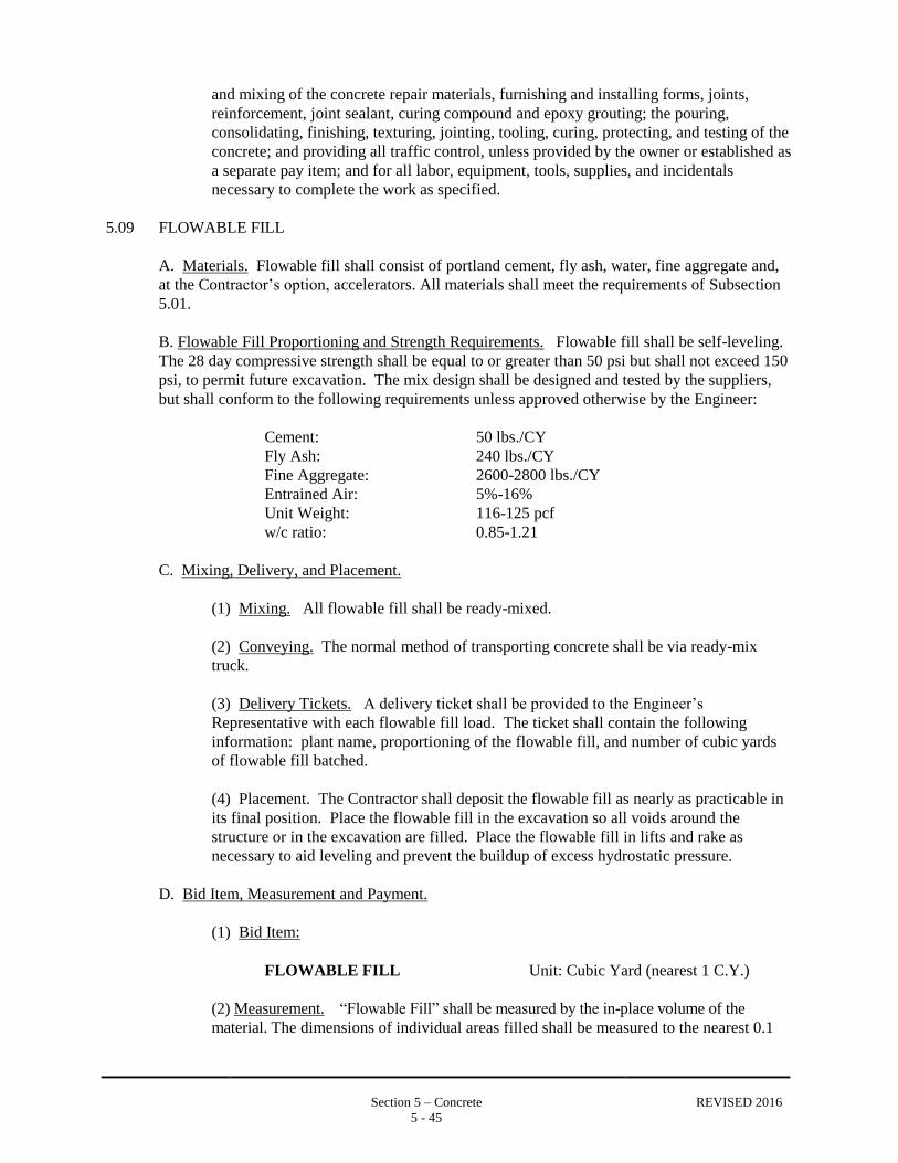
Section 5 – Concrete REVISED 2016
5 - 45
and mixing of the concrete repair materials, furnishing and installing forms, joints,
reinforcement, joint sealant, curing compound and epoxy grouting; the pouring,
consolidating, finishing, texturing, jointing, tooling, curing, protecting, and testing of the
concrete; and providing all traffic control, unless provided by the owner or established as
a separate pay item; and for all labor, equipment, tools, supplies, and incidentals
necessary to complete the work as specified.
5.09 FLOWABLE FILL
A. Materials. Flowable fill shall consist of portland cement, fly ash, water, fine aggregate and,
at the Contractor’s option, accelerators. All materials shall meet the requirements of Subsection
5.01.
B. Flowable Fill Proportioning and Strength Requirements. Flowable fill shall be self-leveling.
The 28 day compressive strength shall be equal to or greater than 50 psi but shall not exceed 150
psi, to permit future excavation. The mix design shall be designed and tested by the suppliers,
but shall conform to the following requirements unless approved otherwise by the Engineer:
Cement: 50 lbs./CY
Fly Ash: 240 lbs./CY
Fine Aggregate: 2600-2800 lbs./CY
Entrained Air: 5%-16%
Unit Weight: 116-125 pcf
w/c ratio: 0.85-1.21
C. Mixing, Delivery, and Placement.
(1) Mixing. All flowable fill shall be ready-mixed.
(2) Conveying. The normal method of transporting concrete shall be via ready-mix
truck.
(3) Delivery Tickets. A delivery ticket shall be provided to the Engineer’s
Representative with each flowable fill load. The ticket shall contain the following
information: plant name, proportioning of the flowable fill, and number of cubic yards
of flowable fill batched.
(4) Placement. The Contractor shall deposit the flowable fill as nearly as practicable in
its final position. Place the flowable fill in the excavation so all voids around the
structure or in the excavation are filled. Place the flowable fill in lifts and rake as
necessary to aid leveling and prevent the buildup of excess hydrostatic pressure.
D. Bid Item, Measurement and Payment.
(1) Bid Item:
FLOWABLE FILL Unit: Cubic Yard (nearest 1 C.Y.)
(2) Measurement. “Flowable Fill” shall be measured by the in-place volume of the
material. The dimensions of individual areas filled shall be measured to the nearest 0.1
Section 5 – Concrete REVISED 2016
5 - 46
foot, the volumes computed by the average end area method and rounded to the nearest 1
cubic yard for each Application for Payment.
(3) Payment. Payment for completed and accepted “Flowable Fill”, measured as
provided above, shall be made at the respective Contract Unit Price. Such payments shall
be full compensation for furnishing and mixing of the materials, furnishing and installing
forms, placing pouring, consolidating, finishing, mobilization and providing all traffic
control, unless provided by the owner or established as a separate pay item, and for all
labor, equipment, tools, supplies, and incidentals necessary to complete the work as
specified.
END OF SECTION