section 6: steel structures california · pdf filesection 6: steel structures california...
TRANSCRIPT
SECTION 6: STEEL STRUCTURES CALIFORNIA AMENDMENTS TO AASHTO LRFD BRIDGE DESIGN SPECIFICATIONS – FOURTH EDITION 6-23A
November 2011
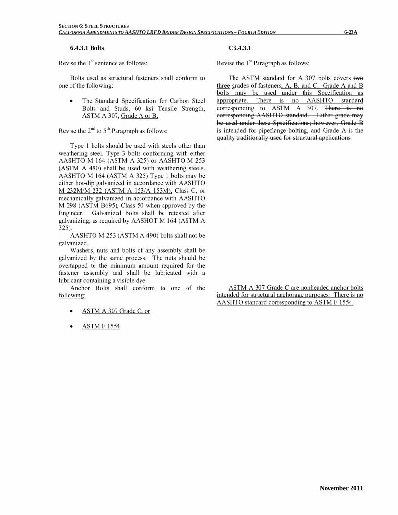
6.4.3.1 Bolts Revise the 1st sentence as follows:
Bolts used as structural fasteners shall conform to
one of the following: • The Standard Specification for Carbon Steel
Bolts and Studs, 60 ksi Tensile Strength, ASTM A 307, Grade A or B,
Revise the 2nd to 5th Paragraph as follows:
Type 1 bolts should be used with steels other than
weathering steel. Type 3 bolts conforming with either AASHTO M 164 (ASTM A 325) or AASHTO M 253 (ASTM A 490) shall be used with weathering steels. AASHTO M 164 (ASTM A 325) Type 1 bolts may be either hot-dip galvanized in accordance with AASHTO M 232M/M 232 (ASTM A 153/A 153M), Class C, or mechanically galvanized in accordance with AASHTO M 298 (ASTM B695), Class 50 when approved by the Engineer. Galvanized bolts shall be retested after galvanizing, as required by AASHOT M 164 (ASTM A 325).
AASHTO M 253 (ASTM A 490) bolts shall not be galvanized.
Washers, nuts and bolts of any assembly shall be galvanized by the same process. The nuts should be overtapped to the minimum amount required for the fastener assembly and shall be lubricated with a lubricant containing a visible dye.
Anchor Bolts shall conform to one of the following:
• ASTM A 307 Grade C, or
• ASTM F 1554
C6.4.3.1
Revise the 1st Paragraph as follows:
The ASTM standard for A 307 bolts covers two three grades of fasteners, A, B, and C. Grade A and B bolts may be used under this Specification as appropriate. There is no AASHTO standard corresponding to ASTM A 307. There is no corresponding AASHTO standard. Either grade may be used under these Specifications; however, Grade B is intended for pipeflange bolting, and Grade A is the quality traditionally used for structural applications.
ASTM A 307 Grade C are nonheaded anchor bolts
intended for structural anchorage purposes. There is no AASHTO standard corresponding to ASTM F 1554.

SECTION 6: STEEL STRUCTURES CALIFORNIA AMENDMENTS TO AASHTO LRFD BRIDGE DESIGN SPECIFICATIONS – FOURTH EDITION 6-24A
November 2011
6.4.3.2 Nuts Revise as follows:
6.4.3.2.1 Nuts Used with Structural Fasteners Nuts used with structural fasteners shall conform to
the following as appropriate. Except as noted below, nuts for AASHTO M 164
(ASTM A 325) bolts shall conform to the Standard Specification for Carbon and Alloy Steel Nuts, AASHTO M 291 (ASTM A 563), Grades DH, DH3, C, C3, and D.
Nuts for AASHTO M 253 (ASTM A 490) bolts shall conform to the requirements of AASHTO M 291 (ASTM A 563), Grades DH and DH3.
Nuts to be galvanized shall be heat treated Grade DH. The provisions of Article 6.4.3.1 shall apply. All galvanized nuts shall be lubricated with a lubricant containing a visible dye.
Plain nuts shall have a minimum hardness of 89 HRB.
Nuts to be used with AASTHO M 164 (ASTM A 325) Type 3 bolts shall be of Grade C3 or DH3. Nuts to be used with AASTHO M 253 (ASTM A 490) Type 3 bolts shall be of Grade DH3.
6.4.3.2.2 Nuts Used with Anchor Bolts Nuts used with anchor bolts shall conform to the
following as appropriate. Nuts for ASTM A 307 Grade C and for ASTM F
1554 anchor bolts shall conform to AASHTO M 291 (ASTM A 563) for appropriate grade and size of anchor bolt.
Nuts to be galvanized shall be heat treated Grade DH or DH3. The provisions of Article 6.4.3.1 shall apply. All galvanized nuts should be lubricated with a lubricant containing a visible dye.

SECTION 6: STEEL STRUCTURES CALIFORNIA AMENDMENTS TO AASHTO LRFD BRIDGE DESIGN SPECIFICATIONS – FOURTH EDITION 6-28A
November 2011
6.5.4.2 Resistance Factors Revise as follows:
Resistance factors, φ, for the strength limit state shall be taken as follows:
• For flexure φf = 1.00 • For shear φv = 1.00 • For axial compression, steel only φc = 0.90 • For axial compression, composite φc = 0.90 • For tension, fracture in net section φu = 0.80 • For tension, yielding in
gross section φy = 0.95 • For bearing on pins in reamed, drilled or bored
holes on milled surfaces φb = 1.00 • For bolts bearing on material φbb = 0.80 • For shear connectors φsc = 0.85 • For A 3258 and A 490 bolts
in tension φt = 0.80 • For A 307 bolts in tension φt = 0.80 • For F 1554 bolts in tension φt = 0.80 • For A 307 bolts in shear φs = 0.75 • For F 1554 bolts in shear φs = 0.75 • For A 325 and A 490 bolts
in shear φs = 0.80 • For block shear φbs = 0.80 • For web crippling φw = 0.80 • For weld metal in complete penetration welds:
o shear on effective area φe1 = 0.85 o tension or compression normal to effective
area same as base metal o tension or compression parallel to axis of the
weld same as base metal • For weld metal in partial penetration welds:
o shear parallel to axis of weld φe2 = 0.80
o tension or compression parallel to axis of weld same as base metal
o compression normal to the effective area same as base metal
o tension normal to the effective area φe1 = 0.80
• For weld metal in fillet welds: o tension or compression parallel to axis of the
weld same as base metal o shear in the throat of weld
metal φe2 = 0.80 • For resistance during pile driving φ = 1.00
SECTION 6: STEEL STRUCTURES CALIFORNIA AMENDMENTS TO AASHTO LRFD BRIDGE DESIGN SPECIFICATIONS – FOURTH EDITION 6-29A
November 2011
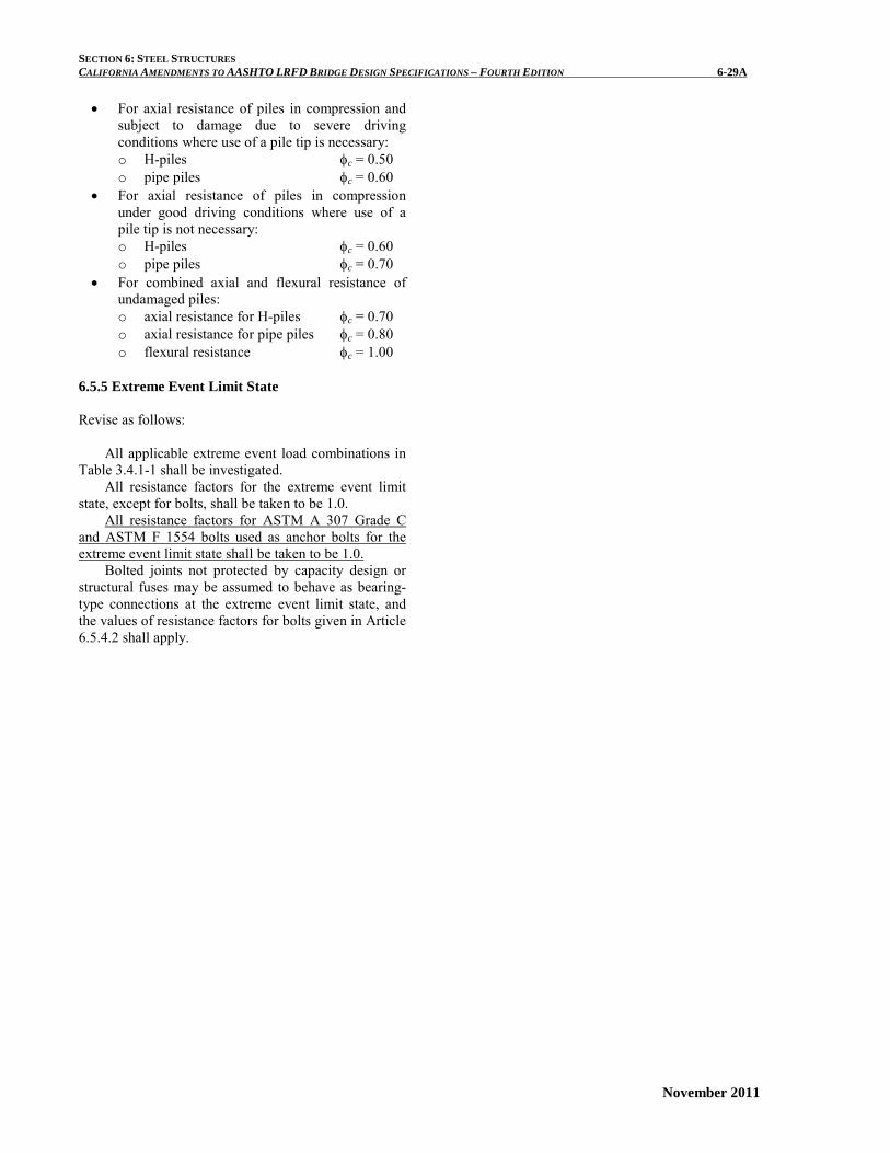
• For axial resistance of piles in compression and subject to damage due to severe driving conditions where use of a pile tip is necessary: o H-piles φc = 0.50 o pipe piles φc = 0.60
• For axial resistance of piles in compression under good driving conditions where use of a pile tip is not necessary: o H-piles φc = 0.60 o pipe piles φc = 0.70
• For combined axial and flexural resistance of undamaged piles: o axial resistance for H-piles φc = 0.70 o axial resistance for pipe piles φc = 0.80 o flexural resistance φc = 1.00
6.5.5 Extreme Event Limit State Revise as follows:
All applicable extreme event load combinations in Table 3.4.1-1 shall be investigated.
All resistance factors for the extreme event limit state, except for bolts, shall be taken to be 1.0.
All resistance factors for ASTM A 307 Grade C and ASTM F 1554 bolts used as anchor bolts for the extreme event limit state shall be taken to be 1.0.
Bolted joints not protected by capacity design or structural fuses may be assumed to behave as bearing-type connections at the extreme event limit state, and the values of resistance factors for bolts given in Article 6.5.4.2 shall apply.
SECTION 6: STEEL STRUCTURES CALIFORNIA AMENDMENTS TO AASHTO LRFD BRIDGE DESIGN SPECIFICATIONS – FOURTH EDITION 6-42A
November 2011
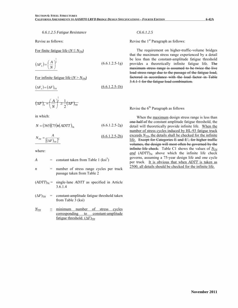
6.6.1.2.5 Fatigue Resistance
Revise as follows: For finite fatigue life (N ≤ NTH)
( ) 31
=∆
NAFn
(6.6.1.2.5-1a)
For infinite fatigue life (N > NTH) ( ) ( )THn FF ∆=∆ (6.6.1.2.5-1b)
( ) ( )THn FNAF ∆≥
=∆
213
1
in which:
( )( ) ( )SLADTTnN 75365= (6.6.1.2.5-2a)
( )[ ]3TH
TH FAN
∆= (6.6.1.2.5-2b)
where: A = constant taken from Table 1 (ksi3) n = number of stress range cycles per truck
passage taken from Table 2 (ADTT)SL = single-lane ADTT as specified in Article
3.6.1.4 (ΔF)TH = constant-amplitude fatigue threshold taken
from Table 3 (ksi) NTH = minimum number of stress cycles
corresponding to constant-amplitude fatigue threshold. (ΔF)TH
C6.6.1.2.5
Revise the 1st Paragraph as follows: The requirement on higher-traffic-volume bridges
that the maximum stress range experienced by a detail be less than the constant-amplitude fatigue threshold provides a theoretically infinite fatigue life. The maximum stress range is assumed to be twice the live load stress range due to the passage of the fatigue load, factored in accordance with the load factor in Table 3.4.1-1 for the fatigue load combination.
Revise the 6th Paragraph as follows
When the maximum design stress range is less than
one-half of the constant amplitude fatigue threshold, the detail will theoretically provide infinite life. When the number of stress cycles induced by HL-93 fatigue truck exceeds NTH, the details shall be checked for the infinite life. Except for Categories E and E’, for higher traffic volumes, the design will most often be governed by the infinite life check. Table C1 shows the values of NTH and (ADTT)SL above which the infinite life check governs, assuming a 75-year design life and one cycle per truck. It is obvious that when ADTT is taken as 2500, all details should be checked for the infinite life.

SECTION 6: STEEL STRUCTURES CALIFORNIA AMENDMENTS TO AASHTO LRFD BRIDGE DESIGN SPECIFICATIONS – FOURTH EDITION 6-42B
November 2011
This page is intentionally left blank.
SECTION 6: STEEL STRUCTURES CALIFORNIA AMENDMENTS TO AASHTO LRFD BRIDGE DESIGN SPECIFICATIONS – FOURTH EDITION 6-43A
November 2011
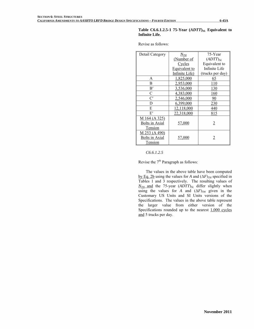
Table C6.6.1.2.5-1 75-Year (ADTT)SL Equivalent to Infinite Life. Revise as follows: Detail Category NTH
(Number of Cycles
Equivalent to Infinite Life)
75-Year (ADTT)SL
Equivalent to Infinite Life
(trucks per day) A 1,825,000 65 B 2,953,000 110 B′ 3,536,000 130 C 4,383,000 160 C′ 2,546,000 90 D 6,399,000 230 E 12,118,000 440 E′ 22,318,000 815 M 164 (A 325) Bolts in Axial
Tension 57,000 2
M 253 (A 490) Bolts in Axial
Tension
57,000
2
C6.6.1.2.5
Revise the 7th Paragraph as follows: The values in the above table have been computed
by Eq. 2b using the values for A and (ΔF)TH specified in Tables 1 and 3 respectively. The resulting values of NTH and the 75-year (ADTT)SL differ slightly when using the values for A and (ΔF)TH given in the Customary US Units and SI Units versions of the Specifications. The values in the above table represent the larger value from either version of the Specifications rounded up to the nearest 1,000 cycles and 5 trucks per day.

SECTION 6: STEEL STRUCTURES CALIFORNIA AMENDMENTS TO AASHTO LRFD BRIDGE DESIGN SPECIFICATIONS – FOURTH EDITION 6-44A
November 2011
Table 6.6.1.2.5-2 Cycles per Truck Passage, n.
Longitudinal Members
Span Length > 40.0 ft. ≤ 40.0 ft.
Simple Span Girders
1.0 2.0
Continuous Girders
1) near interior support
Fatigue I - 1.5 Fatigue II – 1.2
2.0
2) elsewhere 1.0 2.0 Cantilever Griders
5.0
Trusses 1.0 Transverse Members
Spacing > 20.0 ft. ≤ 20.0 ft
1.0 2.0
C6.6.1.2.5
Add a new last Paragraph as follows: Cycles per design fatigue Permit Truck (Fatigue II
limit state) passage are evaluated by the rainflow method. The numbers of cycles induced by the fatigue Permit Truck passage are somewhat similar to the cycles induced by the HL-93 fatigue truck used for Fatigue I Limit State, except in the case of near interior support of bridges that spans greater than 40 feet.

SECTION 6: STEEL STRUCTURES CALIFORNIA AMENDMENTS TO AASHTO LRFD BRIDGE DESIGN SPECIFICATIONS – FOURTH EDITION 6-62A
November 2011
6.7.6.3 Minimum Size Pin for Column
Revise the definition as follows: Fy = specified minimum yield strength of the pin
eyebar (ksi)
SECTION 6: STEEL STRUCTURES CALIFORNIA AMENDMENTS TO AASHTO LRFD BRIDGE DESIGN SPECIFICATIONS – FOURTH EDITION 6-62B
November 2011
This page is intentionally left blank.
SECTION 6: STEEL STRUCTURES CALIFORNIA AMENDMENTS TO AASHTO LRFD BRIDGE DESIGN SPECIFICATIONS – FOURTH EDITION 6-112A
November 2011
6.10.5.3 Special Fatigue Requirement for Webs
Revise the 1st Paragraph as follows: For the purposes of this article, the factored fatigue
load shall be taken as twice that calculated using the Fatigue I Limit State for infinite fatigue life load combination specified in Table 3.4.1-1, with the fatigue live load taken as specified in Article 3.6.1.4.

SECTION 6: STEEL STRUCTURES CALIFORNIA AMENDMENTS TO AASHTO LRFD BRIDGE DESIGN SPECIFICATIONS – FOURTH EDITION 6-112B
November 2011
This page is intentionally left blank.
SECTION 6: STEEL STRUCTURES CALIFORNIA AMENDMENTS TO AASHTO LRFD BRIDGE DESIGN SPECIFICATIONS – FOURTH EDITION 6-115A
November 2011
6.10.6.2.2 Composite Sections in Positive Flexure
Revise the 3rd Paragraph as follows: Compact sections shall satisfy the requirements of
Article 6.10.7.1. Otherwise, the section shall be considered noncompact and shall satisfy the requirements of Article 6.10.7.2

SECTION 6: STEEL STRUCTURES CALIFORNIA AMENDMENTS TO AASHTO LRFD BRIDGE DESIGN SPECIFICATIONS – FOURTH EDITION 6-115B
November 2011
This page is intentionally left blank.
SECTION 6: STEEL STRUCTURES CALIFORNIA AMENDMENTS TO AASHTO LRFD BRIDGE DESIGN SPECIFICATIONS – FOURTH EDITION 6-120A
November 2011
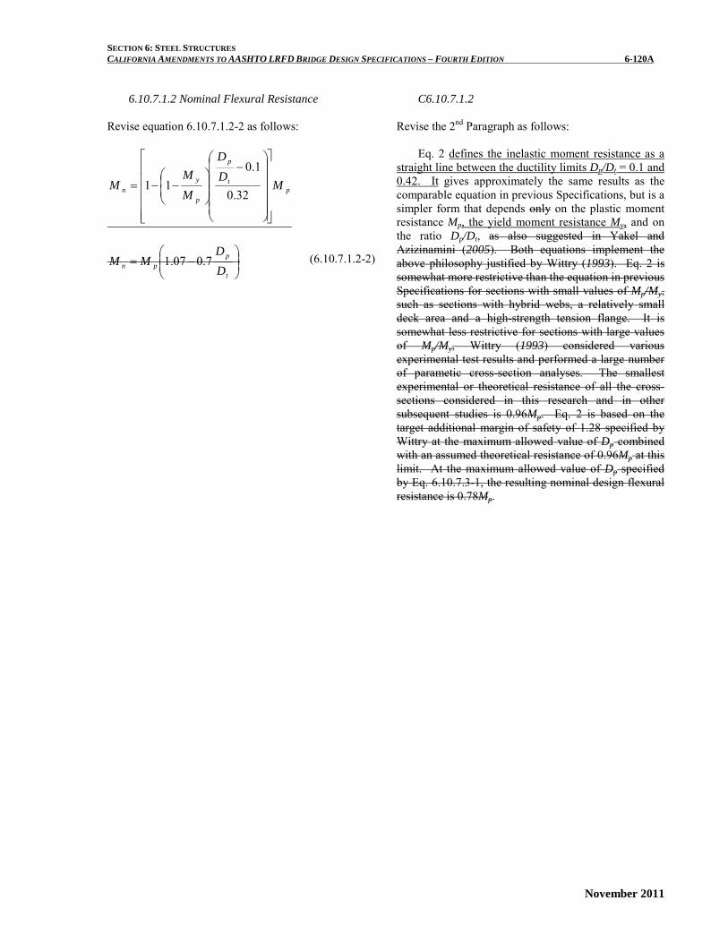
6.10.7.1.2 Nominal Flexural Resistance
Revise equation 6.10.7.1.2-2 as follows:
pt
p
p
yn M
DD
MM
M
−
−−=
32.0
1.011
−=
t
ppn D
DMM 7.007.1 (6.10.7.1.2-2)
C6.10.7.1.2
Revise the 2nd Paragraph as follows: Eq. 2 defines the inelastic moment resistance as a
straight line between the ductility limits Dp/Dt = 0.1 and 0.42. It gives approximately the same results as the comparable equation in previous Specifications, but is a simpler form that depends only on the plastic moment resistance Mp, the yield moment resistance My, and on the ratio Dp/Dt, as also suggested in Yakel and Azizinamini (2005). Both equations implement the above philosophy justified by Wittry (1993). Eq. 2 is somewhat more restrictive than the equation in previous Specifications for sections with small values of Mp/My, such as sections with hybrid webs, a relatively small deck area and a high-strength tension flange. It is somewhat less restrictive for sections with large values of Mp/My, Wittry (1993) considered various experimental test results and performed a large number of parametic cross-section analyses. The smallest experimental or theoretical resistance of all the cross-sections considered in this research and in other subsequent studies is 0.96Mp. Eq. 2 is based on the target additional margin of safety of 1.28 specified by Wittry at the maximum allowed value of Dp combined with an assumed theoretical resistance of 0.96Mp at this limit. At the maximum allowed value of Dp specified by Eq. 6.10.7.3-1, the resulting nominal design flexural resistance is 0.78Mp.

SECTION 6: STEEL STRUCTURES CALIFORNIA AMENDMENTS TO AASHTO LRFD BRIDGE DESIGN SPECIFICATIONS – FOURTH EDITION 6-120B
November 2011
This page is intentionally left blank.
SECTION 6: STEEL STRUCTURES CALIFORNIA AMENDMENTS TO AASHTO LRFD BRIDGE DESIGN SPECIFICATIONS – FOURTH EDITION 6-142A
November 2011
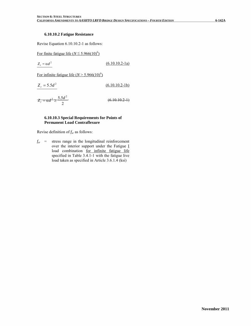
6.10.10.2 Fatigue Resistance
Revise Equation 6.10.10.2-1 as follows:
For finite fatigue life (N ≤ 5.966(10)6)
2dZr α= (6.10.10.2-1a)
For infinite fatigue life (N > 5.966(10)6)
25.5 dZ r = (6.10.10.2-1b)
255 2
2 d.dZr ≥α= (6.10.10.2-1)
6.10.10.3 Special Requirements for Points of Permanent Load Contraflexure
Revise definition of fsr as follows: fsr = stress range in the longitudinal reinforcement
over the interior support under the Fatigue I load combination for infinite fatigue life specified in Table 3.4.1-1 with the fatigue live load taken as specified in Article 3.6.1.4 (ksi)

SECTION 6: STEEL STRUCTURES CALIFORNIA AMENDMENTS TO AASHTO LRFD BRIDGE DESIGN SPECIFICATIONS – FOURTH EDITION 6-142B
November 2011
This page is intentionally left blank.

SECTION 6: STEEL STRUCTURES CALIFORNIA AMENDMENTS TO AASHTO LRFD BRIDGE DESIGN SPECIFICATIONS – FOURTH EDITION 6-146A
November 2011
6.10.11.1.1 General
Revise the 2nd and 4th Paragraphs as follows: Stiffeners in straight girders not used as connection
plates shall be welded to tight fit at the compression flange and fitted tightly to the tension flange., but need not be in bearing with the tension flange. Single-sided stiffeners on horizontally curved girders should be attached to both flanges. When pairs of transverse stiffeners are used on horizontally curved girders, they shall be fitted tightly to both flanges.
The distance between the end of the web-to-
stiffener weld and the near edge of the adjacent web-to-flange or longitudinal stiffener-to-web weld shall not be less than 4tw, nor more than but shall not exceed the lesser of 6tw. In no case shall the distance exceed and 4.0 in.

SECTION 6: STEEL STRUCTURES CALIFORNIA AMENDMENTS TO AASHTO LRFD BRIDGE DESIGN SPECIFICATIONS – FOURTH EDITION 6-146B
November 2011
This page is intentionally left blank.

SECTION 6: STEEL STRUCTURES CALIFORNIA AMENDMENTS TO AASHTO LRFD BRIDGE DESIGN SPECIFICATIONS – FOURTH EDITION 6-147A
November 2011
6.10.11.1.3 Moment of Inertia: Replace Eq. (6.10.11.1.3-3) with the following:
( ) 5.20.2/5.2
2 ≥−=Dd
Jo
(6.10.11.1.3-3)
SECTION 6: STEEL STRUCTURES CALIFORNIA AMENDMENTS TO AASHTO LRFD BRIDGE DESIGN SPECIFICATIONS – FOURTH EDITION 6-148A
November 2011
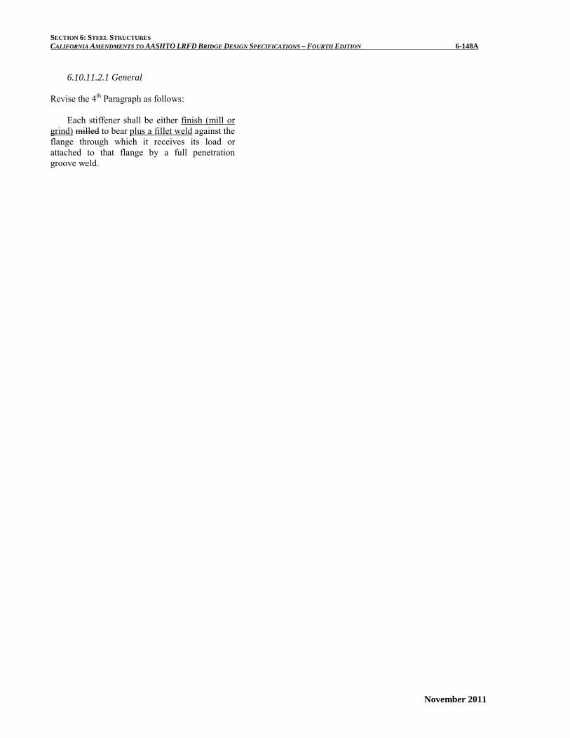
6.10.11.2.1 General
Revise the 4th Paragraph as follows:
Each stiffener shall be either finish (mill or grind) milled to bear plus a fillet weld against the flange through which it receives its load or attached to that flange by a full penetration groove weld.
SECTION 6: STEEL STRUCTURES CALIFORNIA AMENDMENTS TO AASHTO LRFD BRIDGE DESIGN SPECIFICATIONS – FOURTH EDITION 6-185A
November 2011
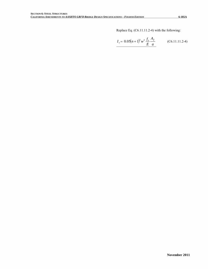
Replace Eq. (C6.11.11.2-4) with the following:
( )a
AEfwn.I fs
t331050 += (C6.11.11.2-4)
SECTION 6: STEEL STRUCTURES CALIFORNIA AMENDMENTS TO AASHTO LRFD BRIDGE DESIGN SPECIFICATIONS – FOURTH EDITION 6-185B
November 2011
This page is intentionally left blank.

SECTION 6: STEEL STRUCTURES CALIFORNIA AMENDMENTS TO AASHTO LRFD BRIDGE DESIGN SPECIFICATIONS – FOURTH EDITION 6-193A
November 2011
6.13.1 General
Except as specified otherwise, connections and splices for primary members shall be designed at the strength limit state for not less than the larger of:
The average of the flexural moment-induced
stress, shear, or axial force due to the factored loadings at the point of splice or connection and the factored flexural, shear, or axial resistance of the member or element at the same point, or
100 75 percent of the factored flexural, shear,
or axial resistance of the member or element.

SECTION 6: STEEL STRUCTURES CALIFORNIA AMENDMENTS TO AASHTO LRFD BRIDGE DESIGN SPECIFICATIONS – FOURTH EDITION 6-194A
November 2011
6.13.2.1 General
Add a 3rd paragraph as follows:
Anchor bolts shall be designed for tension, shear and combined tension and shear as applicable. For global design of anchorages to concrete, refer to Building Code Requirements for Structural Concrete (ACI 318-05) Appendix D.

SECTION 6: STEEL STRUCTURES CALIFORNIA AMENDMENTS TO AASHTO LRFD BRIDGE DESIGN SPECIFICATIONS – FOURTH EDITION 6-200A
November 2011
6.13.2.7 Shear Resistance
Revise the 1st Paragraph as follows: The nominal shear resistance of a high strength
bolt (ASTM A 325 or ASTM A 490) or an ASTM A 307 Bolt (Grade A or B) at the strength limit state in joints whose length between extreme fasteners measured parallel to the line of action of the force is less than 50.0 shall be taken as:
Add a 2nd Paragraph just following definition of Ns as follows:
The nominal shear resistance of an anchor bolt
(ASTM A307 Grade C or ASTM F 1554) at the strength limit state in joints whose length between extreme anchor bolts measured parallel to the line of action of the force is less than 50.0 in. shall be in accordance with Eq. 2.
C6.13.2.7
Revise the 1st sentence of the 2nd Paragraph as follows: The average value of the nominal resistance for
bolts with threads in the shear plane has been determined by a series tests to be 0.833 (0.6Fub), with a standard deviation of 0.03 (Yura et al. 1987).

SECTION 6: STEEL STRUCTURES CALIFORNIA AMENDMENTS TO AASHTO LRFD BRIDGE DESIGN SPECIFICATIONS – FOURTH EDITION 6-200B
November 2011
This page is intentionally left blank.

SECTION 6: STEEL STRUCTURES CALIFORNIA AMENDMENTS TO AASHTO LRFD BRIDGE DESIGN SPECIFICATIONS – FOURTH EDITION 6-206A
November 2011
6.13.2.10.3 Fatigue Resistance
Revise as follows:
Where high-strength bolts in axial tension are subject to fatigue, the stress range, ∆f, ∆f, in the bolt, due to the fatigue design live load, plus the dynamic load allowance for fatigue loading specified in Article 3.6.1.4, plus the prying force resulting from cyclic application of the fatigue load, shall satisfy Eq. 6.6.1.2.2-1.
The nominal diameter of the bolt shall be used in calculating the bolt stress range. In no case shall the calculated prying force exceed 60 30 percent of the externally applied load.
Low carbon ASTM A 307 bolts shall not be used in connections subjected to fatigue.

SECTION 6: STEEL STRUCTURES CALIFORNIA AMENDMENTS TO AASHTO LRFD BRIDGE DESIGN SPECIFICATIONS – FOURTH EDITION 6-206B
November 2011
This page is intentionally left blank.

SECTION 6: STEEL STRUCTURES CALIFORNIA AMENDMENTS TO AASHTO LRFD BRIDGE DESIGN SPECIFICATIONS – FOURTH EDITION 6-216A
November 2011
6.13.6.1.4b Web Splices
Revise the 2nd Paragraph as follows:
As a minimum, at the strength limit state, the
design shear, Vuw, shall be taken as the factored shear resistance of the smaller web at the point of splice, φvVn follows:
• If nvu V.V φ< 50 , then:
uuw VV 5.1= (6.13.6.1.4b-1) • Otherwise:
( )2
nvuuw
VVV
φ+= (6.13.6.1.4b-2)
where: φv = resistance factor for shear specified in Article
6.5.4.2 Vu = shear due to the factored loading at the point
of splice (kip) Vn = nominal shear resistance determined as
specified in Articles 6.10.9.2 and 6.10.9.3 for unstiffened and stiffened webs, respectively (kip)
C6.13.6.1.4b
Delete the 1st Paragraph

SECTION 6: STEEL STRUCTURES CALIFORNIA AMENDMENTS TO AASHTO LRFD BRIDGE DESIGN SPECIFICATIONS – FOURTH EDITION 6-216B
November 2011
This page is intentionally left blank.
SECTION 6: STEEL STRUCTURES CALIFORNIA AMENDMENTS TO AASHTO LRFD BRIDGE DESIGN SPECIFICATIONS – FOURTH EDITION 6-217A
November 2011
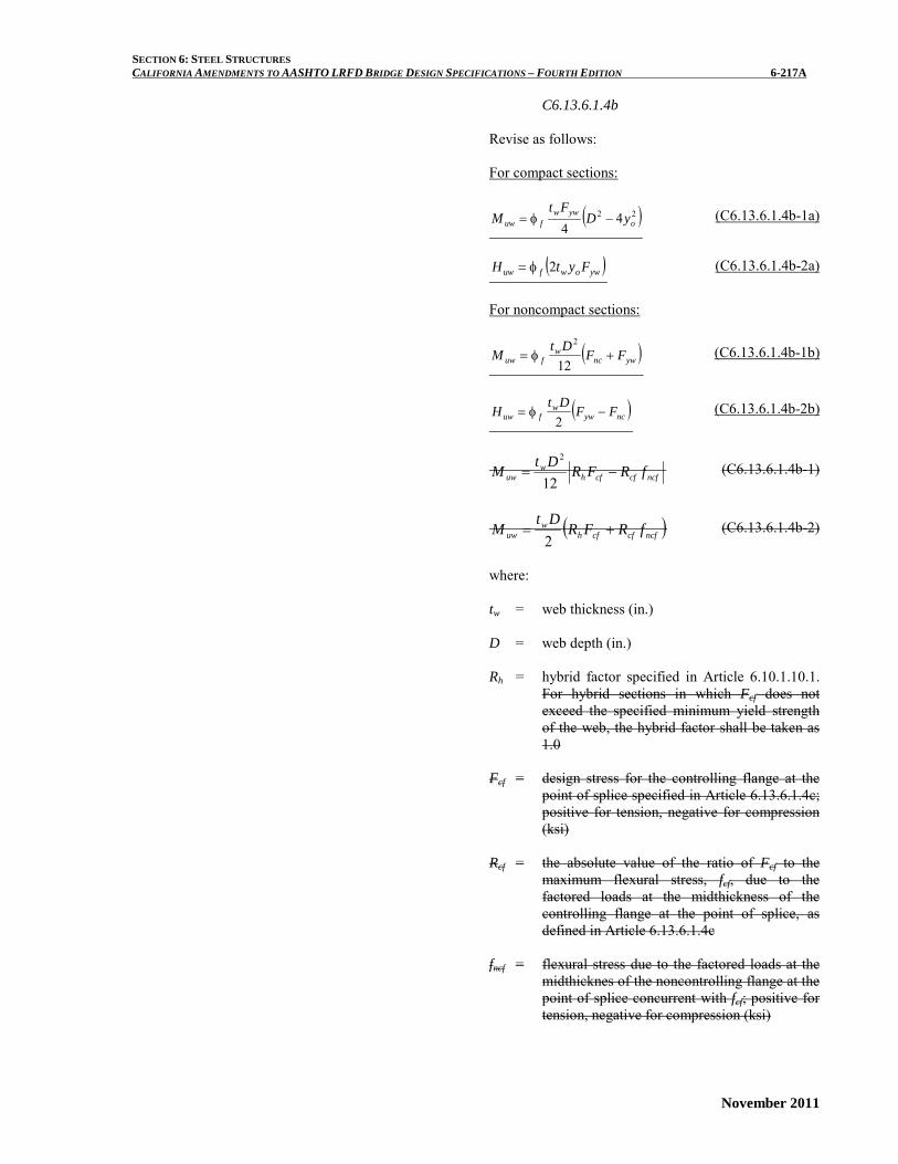
C6.13.6.1.4b
Revise as follows: For compact sections:
( )22 44 o
ywwfuw yD
FtM −φ= (C6.13.6.1.4b-1a)
( )ywowfuw FytH 2φ= (C6.13.6.1.4b-2a)
For noncompact sections:
( )ywncw
fuw FFDt
M +φ=12
2 (C6.13.6.1.4b-1b)
( )ncyww
fuw FFDt
H −φ=2
(C6.13.6.1.4b-2b)
ncfcfcfhw
uw fRFRDt
M −=12
2 (C6.13.6.1.4b-1)
( )ncfcfcfhw
uw fRFRDt
M +=2
(C6.13.6.1.4b-2)
where: tw = web thickness (in.) D = web depth (in.) Rh = hybrid factor specified in Article 6.10.1.10.1.
For hybrid sections in which Fcf does not exceed the specified minimum yield strength of the web, the hybrid factor shall be taken as 1.0
Fcf = design stress for the controlling flange at the
point of splice specified in Article 6.13.6.1.4c; positive for tension, negative for compression (ksi)
Rcf = the absolute value of the ratio of Fcf to the
maximum flexural stress, fcf, due to the factored loads at the midthickness of the controlling flange at the point of splice, as defined in Article 6.13.6.1.4c
fncf = flexural stress due to the factored loads at the
midthicknes of the noncontrolling flange at the point of splice concurrent with fcf; positive for tension, negative for compression (ksi)

SECTION 6: STEEL STRUCTURES CALIFORNIA AMENDMENTS TO AASHTO LRFD BRIDGE DESIGN SPECIFICATIONS – FOURTH EDITION 6-217B
November 2011
Fnc = nominal flexural resistance of the compression flange at the point of splice as specified in Article 6.10.8.2 (ksi)
Fyw = specified minimum yield strength of the web
at the point of splice (ksi) yg = distance from the mid-depth of the web to the
plastic neutral axis (in.) φf = resistance factor for flexure specified in
Article 6.5.4.2
In Eqs. C1 and C2, it is suggested that Muw and Huw be computed by conservatively using the flexural resistance stresses at the midthickness of the compression flanges and specified minimum yield strength of the web. By utilizing the stresses at the midthickness of the flanges, the same stress values can be used for the design of both the web and flange splices, which simplifies the calculations. As an alternate, however, the stresses at the inner fibers of the flanges can be used. In either case, the stresses are to be computed considering the application of the moments due to the appropriate factored loadings to the respective cross-sections supporting those loadings. In Eqs. C1 and C2, the concurrent flexural stress at the midthickness of the noncontrolling flange is factored up in the same proportion as the flexural stress in the controlling flange in order to satisfy the general design requirements of Article 6.13.1. The controlling and noncontrolling flanges are defined in Article C6.13.6.1.4c.

SECTION 6: STEEL STRUCTURES CALIFORNIA AMENDMENTS TO AASHTO LRFD BRIDGE DESIGN SPECIFICATIONS – FOURTH EDITION 6-218A
November 2011
Eqs. C1c and C2c can also be used to compute
values of Muw and Huw to be used when checking for slip of the web bolts. However, the following substitutions must first be made in both equations:
• replace Fcf with the maximum flexural stress,
fs, due to Load Combination Service II at the midthickness of the flange under consideration for the smaller section at the point of splice, replace fncf with the flexural stress, fos, due to Load Combination Service II at the midthickness of the other flange at the point of splice concurrent with fs in the flange under consideration, and
• set the factors Rh and Rcf equal to 1.0. It is not necessary to determine a controlling and noncontrolling flange when checking for slip. The same sign convention applies to the stresses.
ossw
uw ffDt
M −=12
2
(C6.13.6.1.4b-1c)
( )ossw
uw ffDt
H +=2
(C6.13.6.1.4b-2c)
where: fs = maximum flexural stress due to Load
Combination Service II at the extreme fiber of the flange under consideration for the smaller section at the point of splice (positive for tension and negative for compression) (ksi)
fos = flexural stress due to Load Combination
Service II at the extreme fiber of the other flange at the point of splice with fs in the flange under consideration (positive for tension and negative for compression) (ksi)
In Eqs. C1c and C2c, it is suggested that Muw and Huw be computed by conservatively using the stresses at the extreme fiber of the flanges. As an alternate, however, the stresses at the midthickness of the flanges or the inner fibers of the flanges can be used. In either case, the stresses are to be computed considering the application of the moments due to the appropriate factored loadings to the respective cross-sections supporting those loadings.

SECTION 6: STEEL STRUCTURES CALIFORNIA AMENDMENTS TO AASHTO LRFD BRIDGE DESIGN SPECIFICATIONS – FOURTH EDITION 6-218B
November 2011
This page is intentionally left blank.

SECTION 6: STEEL STRUCTURES CALIFORNIA AMENDMENTS TO AASHTO LRFD BRIDGE DESIGN SPECIFICATIONS – FOURTH EDITION 6-220A
November 2011
6.13.6.1.4c Flange Splices
Revise as follows: At the strength limit state, splice plates and their
connections to on the controlling flange shall be proportioned to provide a minimum resistance taken as the design stress, Fcf, times the smaller effective flange area, Ae, on either side of the splice, where Fcf is defined as:
yffcf FF αφ=
yff
yffh
cf
cf F.F
Rf
F αφ≥
αφ+
= 7502
(6.13.6.1.4c-1)
SECTION 6: STEEL STRUCTURES CALIFORNIA AMENDMENTS TO AASHTO LRFD BRIDGE DESIGN SPECIFICATIONS – FOURTH EDITION 6-220B
November 2011
This page is intentionally left blank.

SECTION 6: STEEL STRUCTURES CALIFORNIA AMENDMENTS TO AASHTO LRFD BRIDGE DESIGN SPECIFICATIONS – FOURTH EDITION 6-221A
November 2011
where: fcf = maximum flexural stress due to the factored
loads at the midthickness of the controlling flange at the point of splice (ksi)
Rh = hybrid factor specified in Article 6.10.1.10.1.
For hybrid sections in which Fcf does not exceed the specified minimum yield strength of the web, the hybrid factor shall be taken as 1.0
α = 1.0, except that a lower value equal to (Fn /Fyf)
may be used for flanges where Fn is less than Fyf
φf = resistance factor for flexure specified in
Article 6.5.4.2 Fn = nominal flexural resistance of the flange (ksi) Fyf = specified minimum yield strength of the flange
(ksi) φu = resistance factor for fracture of tension
members as specified in Article 6.5.4.2 φy = resistance factor for yielding of tension
members as specified in Article 6.5.4.2 An = net area of the tension flange determined as
specified in Article 6.8.3 (in.2) Ag = gross area of the tension flange (in.2) Fu = specified minimum tensile strength of the
tension flange determined as specified in Table 6.4.1-1 (ksi)
Fy = specified minimum yield strength of the
tension flange (ksi) Delete the 2nd Paragraph
C6.13.6.1.4c
Delete the 3rd and 5th Paragraph

SECTION 6: STEEL STRUCTURES CALIFORNIA AMENDMENTS TO AASHTO LRFD BRIDGE DESIGN SPECIFICATIONS – FOURTH EDITION 6-222A
November 2011
6.13.6.1.4c Flange Splices Delete Eq. (6.13.6.1.4c-3) Revise Eq. (6.13.6.1.4c-5) as follows:
h
ss R
fF = (6.13.6.1.4c-5)
where:
C6.13.6.1.4c Delete the 7th Paragraph

SECTION 6: STEEL STRUCTURES CALIFORNIA AMENDMENTS TO AASHTO LRFD BRIDGE DESIGN SPECIFICATIONS – FOURTH EDITION 6-223A
November 2011
6.13.6.1.4c Flange Splices
Revise as follows: fs = maximum flexural stress due to Load
Combination Service II at the extreme fiber midthickness of the flange under consideration for the small section at the point of splice (ksi)
Rh = hybrid factor specified in Article 6.10.1.10.1.
For hybrid sections in which fs in the flange with the larger stress does not exceed the specified minimum yield strength of the web, the hybrid factor shall be taken as 1.0
C6.13.6.1.4c
Revise as follows:
For these sections, St. Venant torsional shear must also be considered in the design of box-flange bolted splices at all limit states. St. Venant Torsional shears are typically neglected in top flanges of tub sections once the flanges are continuously braced. The bolts for box-flange splices may be designed for the effects of the Torsional shear using the traditional elastic vector method that is typically applied in the design of web splices. Depending on the limit state under investigation, the shear on the flange bolt group is assumed caused by either the flange force due to the factored loads, or by the appropriate flange design force, as applicable. The moment on the bolt group is taken as the moment resulting from the eccentricity of the St. Venant torsional shear due to the factored loads, assumed applied at the centerline of the splice. At the strength limit state, a design torsional shear due to factored loads should be used, which can be taken as the torsional shear due to the factored loads multiplied by the factor, Rcf, from Eq. 3. The box-flange splice plates in these cases should also be designed at the strength limit state for the combined effects of the calculated design shear and design moment acting on the bolt group.
In cases for straight girders where flange lateral bending is deemed significant, and for horizontally curved girders, the effects of the lateral bending must be considered in the design of the bolted splices for discretely braced top flanges of tub sections or discretely braced flanges of I-sections. The traditional elastic vector method may also be used in these cases to account for the effects of flange lateral bending on the design of the splice bolts. The shear on the flange bolt group is assumed caused by the flange force, calculated as described in the preceding paragraph. The flange force is calculated without consideration of the flange lateral bending. The moment on the bolt group is taken as the flange lateral bending moment due to the factored loads. At the strength limit state, a design lateral bending moment due to the factored loads should be used, which can be taken as the lateral bending moment due to the factored loads multiplied by the factor, Rcf, from Eq. 3. Splice plates subject to flange lateral bending should also be designed at the strength limit state for the combined effects of the calculated design shear and design moment acting on the bolt group. Lateral flange bending can be ignored in the design of top flange splices once the flange is continuously braced.

SECTION 6: STEEL STRUCTURES CALIFORNIA AMENDMENTS TO AASHTO LRFD BRIDGE DESIGN SPECIFICATIONS – FOURTH EDITION 6-223B
November 2011
This page is intentionally left blank.
SECTION 6: STEEL STRUCTURES CALIFORNIA AMENDMENTS TO AASHTO LRFD BRIDGE DESIGN SPECIFICATIONS – FOURTH EDITION 6-225A
November 2011
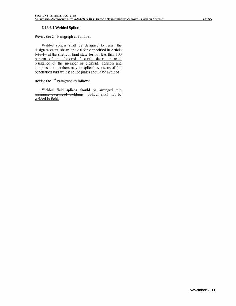
6.13.6.2 Welded Splices
Revise the 2nd Paragraph as follows: Welded splices shall be designed to resist the
design moment, shear, or axial force specified in Article 6.13.1. at the strength limit state for not less than 100 percent of the factored flexural, shear, or axial resistance of the member or element. Tension and compression members may be spliced by means of full penetration butt welds; splice plates should be avoided.
Revise the 3rd Paragraph as follows:
Welded field splices should be arranged tom
minimize overhread welding. Splices shall not be welded in field.

SECTION 6: STEEL STRUCTURES CALIFORNIA AMENDMENTS TO AASHTO LRFD BRIDGE DESIGN SPECIFICATIONS – FOURTH EDITION 6-225B
November 2011
This page is intentionally left blank.
SECTION 6: STEEL STRUCTURES CALIFORNIA AMENDMENTS TO AASHTO LRFD BRIDGE DESIGN SPECIFICATIONS – FOURTH EDITION 6-230A
November 2011
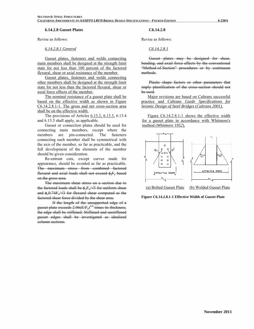
6.14.2.8 Gusset Plates
Revise as follows:
6.14.2.8.1 General Gusset plates, fasteners and welds connecting
main members shall be designed at the strength limit state for not less than 100 percent of the factored flexural, shear or axial resistance of the member.
Gusset plates, fasteners and welds connecting other members shall be designed at the strength limit state for not less than the factored flexural, shear or axial force effects of the member.
The nominal resistance of a gusset plate shall be based on the effective width as shown in Figure C6.14.2.8.1-1. The gross and net cross-section area shall be on the effective width.
The provisions of Articles 6.13.2, 6.13.3, 6.13.4 and 6.13.5 shall apply, as applicable.
Gusset or connection plates should be used for connecting main members, except where the members are pin-connected. The fasteners connecting each member shall be symmetrical with the axis of the member, so far as practicable, and the full development of the elements of the member should be given consideration.
Re-entrant cuts, except curves made for appearance, should be avoided as far as practicable. The maximum stress from combined factored flexural and axial loads shall not exceed φfFy based on the gross area.
The maximum shear stress on a section due to the factored loads shall be φvFu/√3 for uniform shear and φv0.74Fu/√3 for flexural shear computed as the factored shear force divided by the shear area.
If the length of the unsupported edge of a gusset plate exceeds 2.06(E/Fy)1/2 times its thickness, the edge shall be stiffened. Stiffened and unstiffened gusset edges shall be investigated as idealized column sections.
C6.14.2.8
Revise as follows:
C6.14.2.8.1 Gusset plates may be designed for shear,
bending, and axial force effects by the conventional “Method-of-Section” procedures or by continuum methods.
Plastic shape factors or other parameters that
imply plastification of the cross-section should not be used. Major revisions are based on Caltrans successful practice and Caltrans Guide Specifications for Seismic Design of Steel Bridges (Caltrans 2001).
Figure C6.14.2.8.1-1 shows the effective width
for a gusset plate in accordance with Whitmore's method (Whitmore 1952).
(a) Bolted Gusset Plate (b) Welded Gusset Plate Figure C6.14.2.8.1-1 Effective Width of Gusset Plate

SECTION 6: STEEL STRUCTURES CALIFORNIA AMENDMENTS TO AASHTO LRFD BRIDGE DESIGN SPECIFICATIONS – FOURTH EDITION 6-230B
November 2011
6.14.2.8.2 Limiting Unsupported Edge Length to Thickness Ratio
The unsupported edge length to thickness ratio of a gusset plate shall satisfy:
y
g
FE
tL
06.2≤ (6.14.2.8.2-1)
where Lg = unsupported edge length of a gusset plate
(in.) t = thickness of a gusset plate (in.) E = modulus of elasticity of steel (ksi) Fy = specified minimum yield strength of the
gusset plate (ksi) For stiffened edge, the following requirements
shall be satisfied: • For welded stiffeners, slenderness ratio of the
stiffener plus a width of gusset plate equal to ten times its thickness shall be l/r ≤ 40.
• For bolted stiffeners, slenderness ratio of the stiffener between fasteners shall be l/r ≤ 40.
• The moment of inertia of the stiffener shall be
( )
−
≥4
24
2.9
144/83.1
t
tbtI s (6.14.2.8.2-2)
where Is = moment of inertia of a stiffener about its
strong axis (in.4) b = width of a gusset plate perpendicular to the
edge (in.) t = thickness of a gusset plate (in.)
The moment of inertia of the stiffener that is
required to develop the post buckling strength of a long plate has been experimentally determined by Eq. (6.14.2.8.2-2) (AISI 1962)
6.14.2.8.3 Tensile Resistance
The tensile resistance of a gusset plate shall be:
φ
≤φ=φr
unuygyn R
FAFAP (6.14.2.8.3-1)
where An = net cross-section area of a gusset plate (in.2) Ag = gross cross-section area of a gusset plate
(in.2) Fu = specified minimum tensile strength of the
gusset plate (ksi) φu = resistance factor for tension fracture in net
section = 0.80
C6.14.2.8.3
This requirement is to ensure that the tensile
strength is governed by yielding in the gross section, and fracture in the net section and block shear rupture are prevented.

SECTION 6: STEEL STRUCTURES CALIFORNIA AMENDMENTS TO AASHTO LRFD BRIDGE DESIGN SPECIFICATIONS – FOURTH EDITION 6-230C
November 2011
φy = resistance factor for tension yielding in gross
section = 0.95 Rr = factored block shear rupture resistance
specified by Article 6.13.4

SECTION 6: STEEL STRUCTURES CALIFORNIA AMENDMENTS TO AASHTO LRFD BRIDGE DESIGN SPECIFICATIONS – FOURTH EDITION 6-230D
November 2011
6.14.2.8.4 Compressive Resistance
The nominal compressive resistance of a gusset plate, Pn, shall be calculated in accordance with Article 6.9.4.1.
C6.14.2.8.4
The effective length factor, K in Eqs. (6.9.4.1-1) and (6.9.4.1-2) may be taken as 0.6 for the gusset supported by both edges, and 1.2 for the gusset supported by one edge only (AISC 2001); As is the average effective cross section area defined by Whitmore’s method; l is the perpendicular distance from the Whitmore section to the interior corner of the gusset. For members that are not perpendicular to each other as shown in Figure C6.14.8.2.4-1 (AISC 2001), l can be alternatively determined as the average value of
3321 LLL
l++
= (C6.14.2.8.4-1)
Figure C6.14.2.8.4-1Gusset Plate Connection where
L1 = distance from the centerline of the Whitmore section to the interior corner of a gusset plate (in.)
L2, L3 = distance from the outside corner of the Whitmore section to the edge of a member; negative value shall be used when the part of Whitmore section enters into the member (in.)
6.14.2.8.5 Flexural Resistance
The nominal flexural resistance of a gusset plate, Mn, shall be determined by:
yn FSM = (6.14.2.8.5-1)
where S = elastic section modulus of the cross section of
a gusset plate (in.3)

SECTION 6: STEEL STRUCTURES CALIFORNIA AMENDMENTS TO AASHTO LRFD BRIDGE DESIGN SPECIFICATIONS – FOURTH EDITION 6-230E
November 2011
6.14.2.8.6 Shear Resistance
The nominal shear resistance of a gusset plate, Vn, shall be determined by:
gyn AFV 58.0= (6.14.2.8.6-1)
where Ag = gross cross-section area of a gusset plate
(in.2)
6.14.2.8.7 Yielding Resistance under Combined Flexural and Axial Force Effects
The Whitmore’s effective area and other critical areas of a gusset plate subjected the combined flexural and axial force effects shall satisfy the following equation:
1≤φ
+φ
+φ gy
u
yyf
uy
yxf
ux
AFP
FSM
FSM
(6.14.2.8.7-1)
where φf = resistance factor for flexural φ = resistance factor for axial compression = 0.9,
for axial tension yielding = 0.95 Mux = factored moment about x-x axis of the gusset
plate (k-in.) Muy = factored moment about y-y axis of the gusset
plate (k-in.) Pu = factored axial force (kip) Sx = elastic section modulus about x-x axis of the
gusset plate (in.3) Sy = elastic section modulus about y-y axis of the
gusset plate (in.3) Ag = gross area of the gusset plate (in.2) Fy = specified minimum yield strength of the
gusset plates (ksi)
6.14.2.8.8 Out-of-Plane Forces Consideration
For double gusset plate connections, out-of-plane moment shall be resolved into a couple of tension and compression forces acting on the near and far side plates.
For single gusset plate connections, out-of-plane moment and shear are about the weak axis.

SECTION 6: STEEL STRUCTURES CALIFORNIA AMENDMENTS TO AASHTO LRFD BRIDGE DESIGN SPECIFICATIONS – FOURTH EDITION 6-230F
November 2011
This page is intentionally left blank.

SECTION 6: STEEL STRUCTURES CALIFORNIA AMENDMENTS TO AASHTO LRFD BRIDGE DESIGN SPECIFICATIONS – FOURTH EDITION 6-237A
November 2011
Add References ACI. 2005. Building Code Requirements for Structural Concrete. 318-05. American Concrete Institute, Farmington Hills, MI AISC. 2001. Manual of Steel Construction, Load and Resistance Factor Design, 3rd Ed., American Institute of Steel Construction, Chicago, IL. AISI. 1962. Light Gage Cold-Formed Steel Design Manual, American Iron and Steel Institute, Washington, DC. ASCE. 1971. Plastic Design in Steel, A Guide and Commentary, American Society of Civil Engineers, New York, NY. Caltrans, 2001. Guide Specifications for Seismic Design of Steel Bridges, First Edition, California Department of Transportation, Sacramento, CA. Whitmore, R. E. 1952. “Experimental Investigation of Stresses in Gusset Plates,” Bulletin 16, University of Tennessee, Knoxville, TN.
SECTION 6: STEEL STRUCTURES CALIFORNIA AMENDMENTS TO AASHTO LRFD BRIDGE DESIGN SPECIFICATIONS – FOURTH EDITION 6-237B
November 2011
This page is intentionally left blank.