section a - ace industriesx(1)s(i4mq1dzjzrq4...aged wire rope. 4. do not operate hoist with a wire...
TRANSCRIPT

CHESTER HOIST
WORM DRIVE HOISTS
WD-680C
SECTION A
OPERATING and MAINTENANCE INSTRUCTIONS
FOR WD SERIES HOISTS
'/bur Order No. ___ _
Hoist Serial No. ___ _
Model No. ____ _
When ordering parts, please use hoist serial numb9r
CHESTER HOIST Chellter HeMst • P.o. Box 441 • 7573 St. Ate. 45 • Limon, Ohio 44432 • Phone (211) 424-7241 • FAX (218) 424-3128

I. Safety Precautions .
n. Installation Instructions General Instructions
Load Hook Direction (Phasing) Limit Switch Operation (Paddle) Brake Operation
TIl . Operation Operating Personnel
Good Operating Practices
Handling the Load IV . inspection •
v.
Daily Inspection Quarterly Inspection Annual Inspection •
Maintenance
Maintenance Procedure
Adjustments and Repairs .
Lubrication
TABLE OF CONTENTS
•
Wire Rope Inspection , Replacement and Maintenance .
VI. Functional Testing vn. Illustrated Patt8 List VIII . Wiring Diagram
• •
• •
•
Authorization for return must be recelv.d from the Chester Holst ~ returning any equipment for Inspection or warranty repair.
WARNING Th. hoiIting equipment shown In this bulletin la Intended fof
• •
InduItri&I UM only and ahould not be used to 11ft, support or otherwise transport human cargo.
3 3 3 3 3 3 3 3 3 4 4 4 4 5 5 5
5 5
5 8 II

SAFETY PRECAUTIONS
This hoist is designed for safe operation within 'the limits of its rated capacity. There are safety features built into the hoist to protect the operator and others from injury due to failure of the hoist itself. However, listed below are safety pointers which must be followed in order to protect personnel aJld property.
1. Avoid side IlUll or end pull at all times.
2. Limit switches are emergency devices. Do not use limit switches to stop the hoist in normal operation. Do not leave load block in contact with limit switch at end of operation.
3. Do not operate hoist with twisted, kinked or damaged wire rope.
4. Do not operate hoist with a wire rope that is not properly seated in all grooves.
5. Do not operate a damaged or malfunctioning hoist until nncessary adjustments or repairs have been made.
6. Do nol use hoisl to lift, sUllporl, or otherwise transport people or to carry loads over peoll\e.
7. Make sure all supporting structures are strong enough to hold your intended load .
8. Do not lift more than the rated capacity of the hoist.
9. Do not use the wire rope as a substitute for slings.
10. Allow only qual i.fied personnel to op('rate the hoist.
11. Do not leave a load suspended in the air unattended.
12. Avoid jogging controls or quick reversuls of load.
13. Always disconnect hoist from power supply before making electrical connections or repain;.
14. Do not double wrap cable wire rope on drum. 15. Do not use P.B. cable to move either hoist or load
along rail.
II INSTALLATION INSTRUCTIONS 1. GE~ERAL INSTRUCTIONS
a. Thepower suppLy should be within III us or minus 10% of the voltage specified on the hoist nameplate.
b. Supporting structure, including trolleys. monoraiL etc.. should have a load rating at least equal to the hoist plus weight. of hoist.
c. Check lubri cation level in the gear case and trolley gear case (if suppli ed with the hoist).
d. Cheek wire rope for damage!Uld improp{~r seating on the drum and sheavC<sl .
2. LOAD HOOK DlRECl'lON (PHASING) When installing your hoist, make only temporary connections at the JXlwer source. Push the "UP" button and observe the direction of the load block. If the load block raises. the Ilhasing is correct und
permwlent connections may be made at the JXlwer source. If the load block lowers, release the button immediately. To correct load block direction, reverse W1Y two wires (except the green ground wirel at the JXlwer source only . DO NOT CHANGE CONNECTlO~S AT t\!~Y OTHER LOCATION.
3. LiMIT SWITCH OPERATION (PADDLE)
Before placing the hoiRt in operation, check for proper upper limit switch operation. Push the "UP" button wld, while the hoist is moving upward. rai se the limit switch lever. The hook should stop immediately. 00 NOT OPERATE THE HOIST IF THE LIMIT SWlTCB(S) ARE NOT OPERATING PROPERLY.
4. BRAKE OPERATION NOTE: Run in hoist with a light load a few times before lifting the rated load. After lifting a light load a few times, test the hoist per paragraph VI.
Check for load block drift with the Hlaximum rated capac ity load on the hook. If hook does not stop within one to two inches when push button is released it may be necessary to adjust the brake. See p8ragraph V.2.a.(3l.
III OPERATION
I. OPERATING PERSONNEL
It is recommended that hoist operation be limited to the following personnel:
a. Appointed operators who have passed 8. practical operating examination.
b. Maintenwlce and test personnel when it is necessary in the perform!Ulce of their duties.
c. In spectors.
2. GOOD OPERATING PRACTICES
!l. The operator should not engage in any practice which will divert his attention while engaged in operatin g the hoi st.
b. When an "out-of-orcler" sign is on the starting controls, the operator should not power the unit or start operations until the s ign has been removed by a designated person.
c. Before starting the hoist, the operator should be certain that all personnel are clear.
d. The operator should familiarize himself with the equipment and its proper care . If adjustments or rep airs are necessary or any damage known, or suspected, he should reJXlrt the same promptly to the appointed person IlIld should also notify the next operator of the damage upon changing shifts .
e. All control s, such as push button stations, brakes und limit switch(es) should be tested by the operator before beginning a shift. If any controls do not operllte propP.rly, they should be adjusted or repaired before operation s are started.
3

3. HANDLING THE LOAD a. Size of Load
Do not load the hoist beyond the rated load, except for properly authorized tests.
b. Attaching the Load (1) The hoist rope should not be wrapped around
the load. (2) The load should be attached to the hook by
means of slings or other approved devices. (3) The slings or other approved devices shall
be seated properly in the saddle of the hook before operation.
c. Moving the Load 0) The load should not be moved or lifted more
than a few inches until it is well balanced on a sling or lifting device.
(2) Care should be taken in hoisting to be certain that: (a) Hoist rope is not kinked or twisted.
(b) Load does not contact any obstructions.
(c) Multiple part ropes are not twisted about each other.
(3) No hoist should be operated until the hoist unit is centered over the load.
(4) Theoperator should test the brake each time a load approaching the rated load is hWldled by raising the load just enough to clear the floor or supports. and check for brake action. The lift should be continued after the operator is assured the brake is operating properly.
(5) No loaded hoist drum should be rotated in the lowering direction beyond the point where less than two wraps of cable remain on the drum unless a lower limit switch is provided in which case no less than one wrap shall remain.
(6) The operator should inch the hoist into engagement with a load. and avoid unnecessary stops and starts.
~.BlDCK CORRECT THROAT OPENING "X"
3OKG2MO 1-1116 BA-101 1-7/32 BA-102 1-112 BA.-118 1-112 BA.-119 2-1/4 BA-129 2-114 BA-134 1-7/32 BA-144 1-1/2 BA-150 4 BA.-l54 2-112 BA-156 2-114
IV INSPECTION
Inspection procedures are divided into three general classifications based upon the intervals at which inspection should be performed. Deficiencies Rhould be carefully examined and corrected. The intervals between inspection will vary due to operating conditions and amount of use. The following inspection intervals are based on 40 hours per week use under normal environmental conditions. If the hoist is used more than 40 hours per week or under adverse environmental conditions. it should be inspected more frequently.
1. DAILY INSPECTION Inspect the following items daily before operating hoist. a. Check all controls and operating mechanisms
for proper operation.
b_ Check limit switches and brake for proper operation_
c_ Check hooks for deformations, chemical damage, or cracks_ Replace any hook showing any of these signs. If the throat opening is spread wider than listed in Table 1 it has been overstressed Wld must be replaced.
NOTE: Any hook that is twisted or has throat opening in excess of normal. indicates aoose or overloading of the hoist. When a hook is found to be in this condition, other load bearing components of the hoist should be inspected for damage.
d_ Check wire rope for wear, twist or distortion.
e. Check for damaged or improperly working safety latch_
2. QUARTERLY INSPECTION Inspect the following items at 9O-day intervals:
a. Check all items under daily inspection. b. Check for loose bolts, screws and nuts.
c. Inspect drums and sheaves for cracks and excessive wear_
TABLE 1. HOOK THROAT OPENING MEASUREMENTS
4
d. insp{'ct for worn, corroded. cracked or distorted parts.
e. Check for propP!' operation of brake. See par&graph lIA.
r. inspect for excessive wear of wire rope. See paragraph V.4.
g. Check electrical parts for signs of piUing or any deterioration of controls, limit switches and push button station.
3. ANNUAL INSPECTION Inspect the following items annually.
s. Check all items under daily and 9Q-day interval inspection.
b. Check hooks for cracks by means of a magnetic particle test or other suitable crack detecting test.
c. Inspect supporting structure and trolleys (if used) for continued ability to support the imposed loads.
d. Check brake for worn linings and discs. See paragraph V.2.b.(7).
NOTE: A hoist which h.as been idle for a period of one month or more, but less than six months, should be given an inspection of those items listed under paragraphs IV.l and IV.2. A hoist wh.ich has been idle for a period of six months, or more, should be given a complete inspection.
V MAINTENANCE
A preventive maintenance program based on the following should be established for th.e hoist. It is recommended that detailed records be kept and made available to appointed personnel.
NarE: Only parts obtained from Chester should be used in maintenance of the hoist.
l. MAINTENANCE PROCEDURE Before adjustments and repairs are started on the hoist, the following precautions should be taken:
a. The main or emergency switch. on th.e line feeding the hoist sh.ould be locked in the open position or the power disconnected.
b. Warning or "out-of-order" signs should be placed on the hoist. Th.ese signs should be placed and removed only by designated personnel.
2. ADJUSTMENTS AND REPAIRS
Any unsafe condition disclosed by inspection should be corrected before operation of the hoist is resumed. Adjustments and repairs should be accomplished only by qualified personnel. a. Adjustments
Adjustments should be made to assure correct functioning of components after replacements or when malfunctions are detected.
(1) Geared Limit Switch
Adjust geared limit switch according to instructions contained in the maint{'t1ance and parts sheets included in the illustrated parts breakdown. NOTE: The lower limit switch sh.ould not be adjusted to allow less than one full Map of rope on the drum when the limit switch actuates.
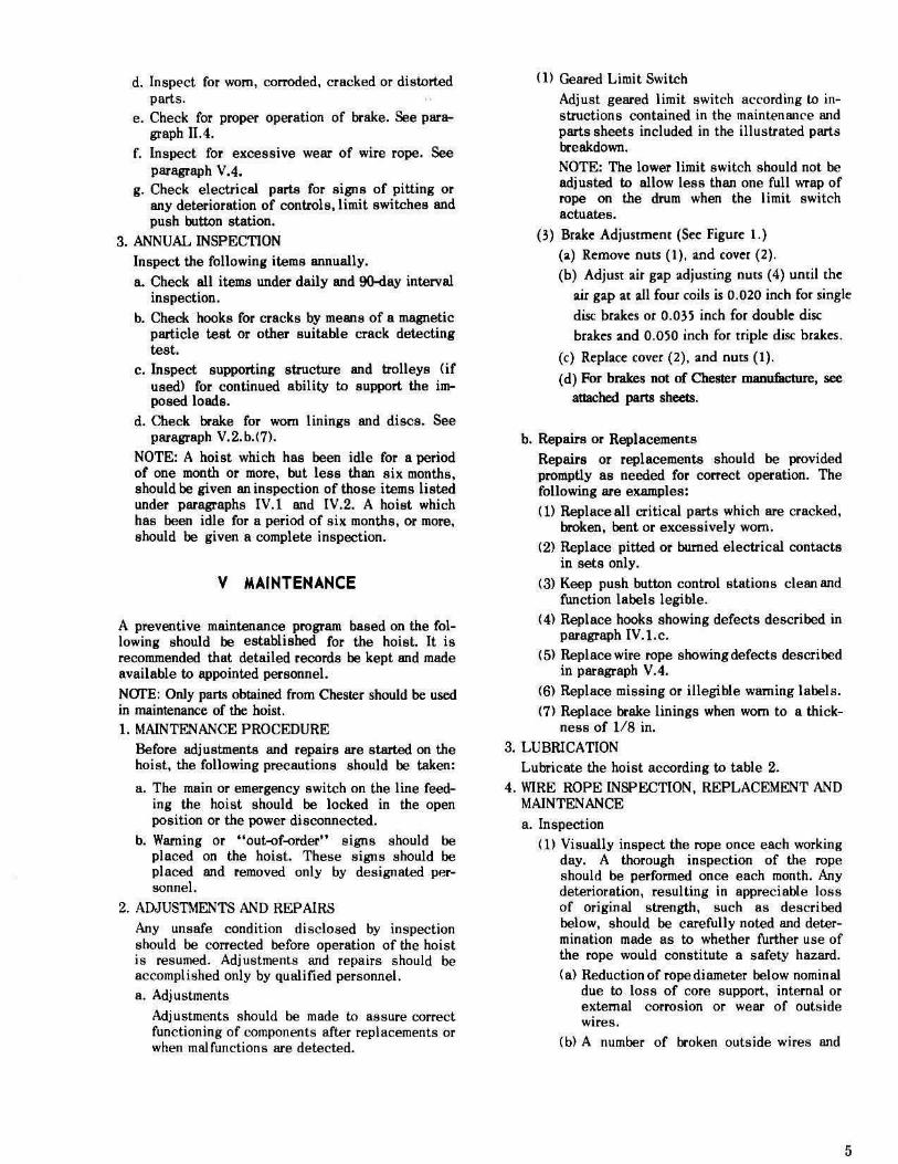
(3) Brak~ Adjustm~nt (S~~ Figur~ I.)
(a) R~mov~ nuts (I), and cover (2).
(b) Adjust air gap adjusting nuts (4) until th~
air gap at all four coils is 0.020 inch for single
disc brak~s or 0.035 inch for double disc brak~s and 0.050 inch for tripl~ disc brakes.
(c) Replac~ cover (2), and nuts (1).
(d) For brakes not of Chester manu&cture, see auached parts sheets.
b. Repairs or Replacements Repairs or replacements should be provided promptly as needed for correct operation. The following are examples: (1) Replace all critical parts which are cracked,
broken, bent or excessively wom.
(2) Replace pitted or burned electrical contacts in sets only.
(3) Keep push. button control stations clean and function labels legible.
(4) Replace hooks showing defects described in paragraph IV.l.c.
(5) Replacewire rope showing defects described in paragraph V A.
(6) Replace missing or illegible warning labels.
(7) Replace brake linings when worn to a th.ickness of 118 in.
3. LUBRICATION Lubricate the hoist according to table 2.
4. WIRE ROPE INSPECTION. REPLACEMENT AND MAINTENANCE
a. Inspection (1) Visually inspect the rope once each working
day. A thorough inspection of the rope should be performed once each month. Any deterioration, resulting in appreciable loss of original strength, such as described below, should be carefully noted WId determination made as to wheth.er furth.er use of the rope would constitute a safety hazard. (a) Reduction of rope diameter below nominal
due to loss of core support, internal or external corrosion or wear of outside wires.
(b) A number of broken outside wires and
5
6
BRAKE COil CONNECTIONS
230/_'011 230V 46011 Zoo/lOI\lOAn5"
" " .. " "[]~O " ::l f3 [
d J[
" " " " " " " " " " " " " " " " " l/LJ lrJ\J l!tJ lJ:A:\J
2001208Y 200V COIL
1115\1 COllSI 11' 511 COltS) 12JDY COlli) SHiV · SHoV COil SINGLE "EED 2 SPHO 2 'PflO SINGLE SPfEO
FIGURE 1. BRAKE ADJUSTMENT
the degree of dietrib.ition or concentration of such broken wires.
(e) Wom outside wires.
(d) Sections of rope which are nonnally hidden dwing inspection or maintenance procedures, such 8a parta pusing over ebe.vee, should be given close inspection 8e these are pointe most subject to deterioration.
(e) Corroded, or Iroken wires at end connectiona.
(0 CorTOded, cracked. bent, wom or improperly applied end connections.
(g) Kinking, crushing, cutting or unsttanding. (2) All rope which has been idle (or a month or
more should be given a thorouKh inspection before it is placed in service.
b. Replacement
(1) No precise rules can be giveo for determ.inationof the exact time for replacement of wire rope, 8ince many variable factors are involved. Conditione such &8 the following should be sufficient for questioning rope safety and consideration of replacement: (a) Any broken wire.
(b) Wear of one--thirrl of the original diameter of outside individual wires.
(d Kinking, crushini, birdcaging or any other damage resulting in distortion of the rope structure.
Cd) Evidence of any heat damage from any cause.
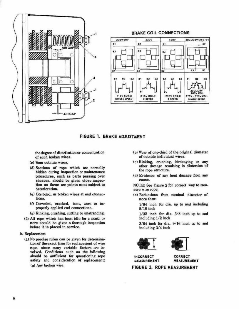
NOTE: See figure 2 for correct way to measure wire rope. (e) Reductions from nominal diameter of
more than : 1164 inch (or dia. up to and including 5/16 inch 1/32 inch for dia. 3/8 inch up to and including 1/ 2 inch
3/64 inch for die. 9/16 inch up to and including 3/4 inch
INCORRECT MEASUREMENT
CORRECT MEASUREMENT
FIGURE 2. ROPE MEASUREMENT

PART TO BE LUBRICANT INSTRUCTIONS FREQUENCY LUBRICATED " Transmission Mobilg~ar #634 Drain from drain plug in bottom After initial SO
or ~quival~nt. of housing. Fill to leve l plug hours operation. on side of hou s ing. then every 3
months or Motorized Troll ey Mobilg~aI #634 Drain by means of drain plug 500 hours. Gear Box or ~quivalc:nt. in bottom of housing. Fill
to level plug on side of housing.
Wire Rope Heayy motor oil or Apply I ight coat to 30 days. a cable compound enti re rope.
Load Block Darina #2 or equivalent. Lubrication is required only 30 days. when sheave pin contains grease fittings.
TABLE 2. LUBRICATION
( 2) Special attention shoul d be given to e nd fastenings. Ropes shou ld be examined frequently at fittings . and upon the devel opment of lUly broken wirell, the roPf! s hould be replac(.>d. Rope length should 00 sufficient for proper operation.
KOTE: Check fot proper operation of geared I inti t s wi t.ch.
(3) Replacement rope should be obtained from Chester and should be the same size, grade and construction as the original rope installed on the hoist.
CAUTION: Th e main precaution to be taken in removing and installing wire rope is to avoid kinking which greatly IClssens its strength and useful life.
(4) 2 P.S. and ·1 P.S. Si nglto and Twin Hook Rope ReplacClment. &>0 figure 4.
(a) Remove wire rope where anchored to framE".
f b) Remove load blOC'k from wire ropl'.
(e) Unwind wire rope from drum by roulling drum until rope is completely played out, Pull rope from drum hy pulling rope clamp through hole in drum guard until tt few feet of rope re mains to be pulled through drum .
(d) Attac h e nd of new rope to end of old rope with a s trong tape or wire leade r and pull ncw rope through drum until seveml feel extend from drum t hrough drum guard. Remove tape.
(e) Assemhle ca hle domp to new wi re ropl'
as shown in figurc ~l.
(/1 Pull rlt'w rope bu('k through drum until t'l1b\c ei llmp i!l i<f'oted in hub of drum
opposite gea r case.
(g) Rotate drum to wind rope on drum. Make su re that the first few turns of rope are wound tightly on drum find that rope is correctly located in grooves of drum.
(h) Reeve rope around load block(and shecve for 4 P .S.).
( i ) Attach e nd fitting to rope as s hown in figurE" 3 and anchor to frame.
(5) 2 P.O. and 4 P .O. Rope Replacement. Sec figure 4.
(a) Rotate drum until fOpt'. is completely unwound from drum.
(b) Pull one end of wire rope from drum through hole in drum guard. Remove end attachment from wire rope.
(c) Attach end of new rope to end of old rope with a s trong tape and pull ne w rope through end of dnJID through opening in drum guard.
Id) Ree\'e new rope through hook block sheaves and idler sheaye(s) . Pull rope through opening in opposite end of drum Wid back tttrough drum until several feet of the new rop~ extend from drum.
(e) Assem ble cabl e clamp to both ends of new wire rope as shown in rlgurCl 3.
(n Rotate drum to wind rope on drum. Make sure that the first few turns of ropE" are wound tightly on drum and that rope is correcLly located in grooyes of drum.
7

~~~ Q) Attach first c l ip
DR UM ANCHOR
SIZE F OR MIN. NO. C LIP S MIHUMUM SPAC ING ROPE 0 1.4.. FOR MAXIMUM BETWEEN C LI PS IHCHES STRENGTH INCHES
1/. 2 1-1/2 5/ 16 2 1_7/ 8 3/ 8 2 2-1/4 71 16 3 2-5/8
HOW TO AT TACH WIRE ROP E CLIPS
The right way to attach wire rope clips is illustrated at left. The base or saddle should bear on the l ive end of the rope_lJ-bolt on the short or dead end. Staggering or reversing the clips does NOT give additional holding power.
ATTACH FIRST CLIP one base width from dead end of rope. Tighten nuts securely,
ATTACH SECOND CLIP 8S close to loop as pOSSi
ble. Tighten nuts finnly but not completely tight.
A'ITACH ALL OTHER CLIPS (i f required) equally spaced between the fi rst two. Tighten nuts finnly.
Apply a slight tension to the rope and alternately and unirormly tighten all nuts securel y. Nuts should be fe-tightened after application of the initial load to oompensate for any reduction of rope diameter. They should be checked at periodi c intervals. For maximum hol d,i ng power and rope strength, use the number of clips and spacing fo r each size rope shown in table above. Where service conditions are unusually severe, the number of clips should be increased.
FIGURE 3. WIRE ROPE CLIP ATTACHMENT
VI FUNCTIONAL TESTING
Af\er load sustaining parts have been al tered, replaced or repaired, the hoist should be load tested. Theooist should be tested using 100 percent of rated load.
8

ANCHOR THROUGH DRUM
ANCHOR TO FRAME
DRUM
lOAD BLOCK SHEAVE
JHOOK
ANCHOR THROUGH DRUM
XXX ANCHOR TO FRAME
lOAD BLOCK SHEAVE
'.
JHOOK
IDLER SHEAVE ATTACHED TO FRAME
lOAD BLOCK SHEAVE
2 P. S. 4 P. S. SINGLE & TWIN HOOK
lOAD BLOCK SHEAVE
lOAD BLOCK
" . ...• " SHEAVE
JHOOK 2 P. D.
ANCHOR BOTH ENDS THROUGH DRUM
lOAD BLOCK
DRUM
SHEAVE " •...• OY "' •• ___ "
JHOOK 4 P. D.
ANCHOR ROPE OPPOSITE GEAR CASE ON All GEAR
DRUM DRUM
lH HEliX RH HELIX
MOTOR
FIGURE 4. DIAGRAMS FOR REPLACING WIRE ROPE
LOAD BLOCK
x,-."" SHEAVE
9

TABLE 3. TROUBLESHOOTING
TROUBLE CAUSE REMEDY
Hook Fails to Stop at 1. Improperly adjusted brake. 1. Adjust per para. V.2.H.(3), End of Travel 2. Worn brake linings. 2. Repl ace when worn beyond limits specifi ed
in para. V.2. b,(7L 3. Magnetic revers ing controll er 3. Check out reversing controll er.
malfunction.
Hoist Does Not Respon d 1. Power failum in supply lines . 1. Check circuit breakers, switches and to Push Button connections in power lines .
2. Wrong voltage or frequency. 2. Check voltage and frequency of power supply against the rating on the hoist nwnepiate.
3. Brake does not release. 3. Check brake adjustment. (See para. V.2.a,(3l , Check coonectiona to brake coi la for open or short circuit.
4. Improper connections in hoist or 4. Check aU connections at I ine connectors push button station. and on terminal block.
5. Faulty magnetic controller. 5. Check coil s for open or short circuiL Check all connections in control circuit. Check for burned contacts. Replace as needed.
Hook Does Not Stop I. Hoist overl oaded. 1. Reduce load tn within rated capacity of Promptly hoist.
2. Brake not holding. 2. Check brake adjustment (see V.2.a.(3})' Check brake Linings for wear. See para. V.2.b.(7).
Hook Moves in Wrong 1. Three-phase reversal. I. Reverse any two wires (except the green Direction ground wire) at the power source.
2. Improper connections. 2. Check all connections against Wiring Diagram.
Hook Raises But Will 1. "Oown" circuit open. 1. Check circuit fOt' loose connections. Check Not Lower " Down" li mit switch for malfunction.
2. Broken conductor in push 2. Check each conductnr in the ca ble. If one button cable. is broken, replace entire cable.
3. Faulty magnetic controller. 3. Check coils for open or short circuit. Check all connections in control circuit. Check for burned contacts. Replace as needed .
Hook Lowers But Will 1. Hoisl overloaded. 1. Reduce load to within rated capacity. Not Raise 2. Low voltage. 2. Determine cause of low voltage and bring
up to within plus or minus 10% of the voltage specified on the hoist.
3. "UP" circuit open. 3. Check circuit for loose cOMections. Check "UP" limit switch ror malrunction.
4. ~ken conductor in push 4. Check each conductor in the cable. If one button cable. is broken. replace entire cable.
5. Faulty magnetic controll er. 5. Check coil s for open or short circuit. Check all connections in control circuit. Check for burned contacts. Repl ace as needed.
Lack of Proper Lining 1. Hoist overloaded. 1. Reduce load to within rated capacity of Speed hoi st.
2. Brake not releasing full y. 2. Check brake adjustment. See para. V.2.8.(3). 3. Low Voltage. 3. Bring up voltage to plus or minus 10% of
of voltage specified on hoist.
10

VII ILLUSTRATED PARTS LIST
GENERAL
The illustrated parts list that follow are designed to help you identify replacement parts for your Chester hoist. In addition to expJOOed illustrations which cover a large part of your hoist, some manufacturers' sheets are included for such items as geared limit switches, magnetic reversing controllers, relays and other items. If assistance is required please contact your Chester representative.
HOW TO USE THE PARTS LISTS
1b identify a part from your hoist. locate the illustration for the affected section of the hoist. Study the illustration and locate the part you wish to fiod. An arrow will be pointing to the part from a number. This figure number will be found in the accompanying parts list with the part name, part Dumber and quantity required.
When ordering parts, please send the following infonnation.
1. Serial Number of your hoist. 2. Your power supply (voltage, phase and cycles).
3. TItle of illustration (for example, TA2A 2-WHEEL PLAIN TROLLEy).
4. Figure Number, Part Name, Quantity Required and Part Number.
5. Any additional information required by notes at the bottom of parts lists.
-"S.R",L NUMBER
II

WARRANTY All goods sold by SELLER hereunder are sold with only the following warranty: SELLER warrants that the goods shall be free from defects in material and workmanship under normal use and service. SEllER'S obligation under this warranty Is limited to reworking or rtlplaclng at its option, any goods, which, within Ina time stated herein, shall be returned to it al its place of business at the address set forth herein with two-way packaging and shipping costs prepaid, and which upon examination and determination by SELLER, shall be found to have been thus defective. The rework, repair or replacement of defective goods under this warranty will be made without chaJge !of malarial or labor. This warranty shall remain In forca and be valid on goods manufactured by SELLER, or manufactured by others to SELLER'S detailed design lor 12 months from the dale of shipment by SELLER to BUYER. THE WARRANTY PROVIDED IN THIS ARTICLE 1, THE OBLIGATIONS AND LIABILITIES OF SELLER HEREUNDER AND THE RIGHTS AND REMEDIES OF BUYER HEREUNDER ARE EXCLUSIVE AND IN SUBSTITUTION FOR, AND BUYER HEREBY WAIVES, ALL OTHER WARRANTIES, GUARANTEES, OBLIGATIONS, LIABILITIES, RIGHTS AND REMEDIES, EXPRESSED OR IMPLIED, ARISING BY IJW OR OfHERlNISE, INCLUDING BUT NOT LIMITED TO THE IMPLIED WARRANTY OR MERCHANTABILITY, ANY IMPUED WARRANTY ARISING FROM COURSE OR PERFORMANCE, COURSE OF DEALING OR USAGE OF TRADE, ANY IMPLIED WARRANTY OF FITNESS AND ANY OBLIGATION OR LIABILITY OF SELLER ARISING FROM lOAT, OF FOR LOSS OF USE, REVENUE OR PROFIT, OR FOR INCIDENTAL OR CONSEQUENTIAL DAMAGES. SELLER SHALL NOT BE LIABLE UNDER ANY CIRCUMSTANCES FOR MORE THAN THE REPLACEMENT
OR REFUND OFTHE PURCHASE PRICE ON DEFECnVE GOODS. Goods which are allegedly defective may not be returned to SELLER without prior written approval of SELLER. SELLER, at its option, may first request samples for Inspection purposes. The provisions of this warranty shall not apply 10, nor is any other warranty glven on, goods which have not been used or maintained In accordance with SELLER'S instructions or which have been subject to misuse, negligence or accident or which have been repaired, ailered or modified In any way by anyone other than the SELLER. SELLER makes no warranty, expressed or Implied (Including without limiting the generality of the foregoing, any warrantles of merchantability or fitness) with respect to any (accessory) goods not manufactured by SELLER. With respect to any such goods sold by SELLER 10 BUYER hereunder, Including purchased goods Incorporated in goods manufactured by SELLER, BUYER agrees to took solely to the manufacturer of such goods for any warranty. BUYER waives all claims other than claims based on SELLER'S expressed warranty or the added cost of replacement due to SELLER'S failure to deliver the goods purchased hereunder. Such walved claims shalt inctude but not be limited to claims based on strict tort liability and other economic losses such as loss of profits, loss of business opportunity and loss of goodwill. Upon request, SELLER will furnish such technical advice or assistance as It has available In reference to the use of the goods; however, It Is expressly understood that (I) SELLER assumes no obligation or liability for the advice or assistance given or results obtained, (iI) all such advice or assistance Is given and accepted at BUYER'S risk, and (iii) such advice or assistance shall not increase or alter SELLER'S liability as herein defined and limited .
WARNING The hoisting equipment shown in this bulletin is intended for industrial use only
and should not be used to lift, support, or otherwise transport human cargo.
@CH£8TER HOIST p.o. 80X 44. 7573 ST. RYE. 45 USBON, OHIO 44432 U.S.A.