section d - k f · pdf file · 2016-07-11section d controls table of contents ......
TRANSCRIPT
D-109-09
Section DCONTROLSTABLE OF CONTENTS
HAWK ICS LEVEL COMPARISON . . . . . . . . . . . . . . . . . . . . . . . . . . . . . . . . . . . . . . . . . . . . . . . . . . . . . . . . . . D-4
CB-HAWK ICS BOILER MANAGEMENT CONTROL SYSTEM . . . . . . . . . . . . . . . . . . . . . . . . . . . . . . . . . . . . . . . D-5FEATURES AND BENEFITS . . . . . . . . . . . . . . . . . . . . . . . . . . . . . . . . . . . . . . . . . . . . . . . . . . D-5PRODUCT OFFERING . . . . . . . . . . . . . . . . . . . . . . . . . . . . . . . . . . . . . . . . . . . . . . . . . . . . . . D-7ENGINEERING DATA . . . . . . . . . . . . . . . . . . . . . . . . . . . . . . . . . . . . . . . . . . . . . . . . . . . . . . D-7SAMPLE SPECIFICATIONS . . . . . . . . . . . . . . . . . . . . . . . . . . . . . . . . . . . . . . . . . . . . . . . . . . D-8SPECIFICATIONS - PARALLEL POSITIONING . . . . . . . . . . . . . . . . . . . . . . . . . . . . . . . . . . . . . . D-12
CB-HAWK ICS COMBUSTION AIR FAN VARIABLE SPEED DRIVE . . . . . . . . . . . . . . . . . . . . . . . . . . . . . . . . . D-15FEATURES AND BENEFITS . . . . . . . . . . . . . . . . . . . . . . . . . . . . . . . . . . . . . . . . . . . . . . . . . . D-15PRODUCT OFFERING . . . . . . . . . . . . . . . . . . . . . . . . . . . . . . . . . . . . . . . . . . . . . . . . . . . . . . D-15ENGINEERING DATA . . . . . . . . . . . . . . . . . . . . . . . . . . . . . . . . . . . . . . . . . . . . . . . . . . . . . . D-16SAMPLE SPECIFICATIONS . . . . . . . . . . . . . . . . . . . . . . . . . . . . . . . . . . . . . . . . . . . . . . . . . . D-17
CB-HAWK ICS OXYGEN MONITORING SYSTEM . . . . . . . . . . . . . . . . . . . . . . . . . . . . . . . . . . . . . . . . . . . . . . D-18FEATURES AND BENEFITS . . . . . . . . . . . . . . . . . . . . . . . . . . . . . . . . . . . . . . . . . . . . . . . . . . D-18PRODUCT OFFERING . . . . . . . . . . . . . . . . . . . . . . . . . . . . . . . . . . . . . . . . . . . . . . . . . . . . . . D-19ENGINEERING DATA . . . . . . . . . . . . . . . . . . . . . . . . . . . . . . . . . . . . . . . . . . . . . . . . . . . . . . D-19SAMPLE SPECIFICATIONS . . . . . . . . . . . . . . . . . . . . . . . . . . . . . . . . . . . . . . . . . . . . . . . . . . D-19
CB-HAWK ICS — ETHERNET . . . . . . . . . . . . . . . . . . . . . . . . . . . . . . . . . . . . . . . . . . . . . . . . . . . . . . . . . . . D-21FEATURES AND BENEFITS . . . . . . . . . . . . . . . . . . . . . . . . . . . . . . . . . . . . . . . . . . . . . . . . . . D-21PRODUCT OFFERING . . . . . . . . . . . . . . . . . . . . . . . . . . . . . . . . . . . . . . . . . . . . . . . . . . . . . . D-21ENGINEERING DATA . . . . . . . . . . . . . . . . . . . . . . . . . . . . . . . . . . . . . . . . . . . . . . . . . . . . . . D-21SAMPLE SPECIFICATIONS . . . . . . . . . . . . . . . . . . . . . . . . . . . . . . . . . . . . . . . . . . . . . . . . . . D-22
CB-HAWK ICS — PAGING and REMOTE DIAL-UP ACCESS with MODEM . . . . . . . . . . . . . . . . . . . . . . . . . . . . D-23FEATURES AND BENEFITS . . . . . . . . . . . . . . . . . . . . . . . . . . . . . . . . . . . . . . . . . . . . . . . . . . D-23PRODUCT OFFERING . . . . . . . . . . . . . . . . . . . . . . . . . . . . . . . . . . . . . . . . . . . . . . . . . . . . . . D-23ENGINEERING DATA . . . . . . . . . . . . . . . . . . . . . . . . . . . . . . . . . . . . . . . . . . . . . . . . . . . . . . D-23SAMPLE SPECIFICATIONS . . . . . . . . . . . . . . . . . . . . . . . . . . . . . . . . . . . . . . . . . . . . . . . . . . D-23
CB-HAWK ICS — LEAD/LAG FOR TWO BOILER SYSTEMS . . . . . . . . . . . . . . . . . . . . . . . . . . . . . . . . . . . . . . D-24FEATURES AND BENEFITS . . . . . . . . . . . . . . . . . . . . . . . . . . . . . . . . . . . . . . . . . . . . . . . . . . D-24PRODUCT OFFERING . . . . . . . . . . . . . . . . . . . . . . . . . . . . . . . . . . . . . . . . . . . . . . . . . . . . . . D-24SAMPLE SPECIFICATIONS . . . . . . . . . . . . . . . . . . . . . . . . . . . . . . . . . . . . . . . . . . . . . . . . . . D-25APPLICATION AND SYSTEM REQUIREMENTS . . . . . . . . . . . . . . . . . . . . . . . . . . . . . . . . . . . . D-25
CB-HAWK ICS — LEAD/LAG for up to EIGHT BOILERS SYSTEM . . . . . . . . . . . . . . . . . . . . . . . . . . . . . . . . . . D-26FEATURES AND BENEFITS . . . . . . . . . . . . . . . . . . . . . . . . . . . . . . . . . . . . . . . . . . . . . . . . . . D-26PRODUCT OFFERING . . . . . . . . . . . . . . . . . . . . . . . . . . . . . . . . . . . . . . . . . . . . . . . . . . . . . . D-27SAMPLE SPECIFICATIONS . . . . . . . . . . . . . . . . . . . . . . . . . . . . . . . . . . . . . . . . . . . . . . . . . . D-27APPLICATION AND SYSTEM REQUIREMENTS . . . . . . . . . . . . . . . . . . . . . . . . . . . . . . . . . . . . D-28

Section D
D-2
09-09
CB780E CONTROL . . . . . . . . . . . . . . . . . . . . . . . . . . . . . . . . . . . . . . . . . . . . . . . . . . . . . . . . . . . . . . . . . . . D-29FEATURES AND BENEFITS . . . . . . . . . . . . . . . . . . . . . . . . . . . . . . . . . . . . . . . . . . . . . . . . . . .D-29PRODUCT OFFERING . . . . . . . . . . . . . . . . . . . . . . . . . . . . . . . . . . . . . . . . . . . . . . . . . . . . . . .D-30ENGINEERING DATA . . . . . . . . . . . . . . . . . . . . . . . . . . . . . . . . . . . . . . . . . . . . . . . . . . . . . . .D-30SAMPLE SPECIFICATION . . . . . . . . . . . . . . . . . . . . . . . . . . . . . . . . . . . . . . . . . . . . . . . . . . . .D-31
CB120-120E CONTROL . . . . . . . . . . . . . . . . . . . . . . . . . . . . . . . . . . . . . . . . . . . . . . . . . . . . . . . . . . . . . . . D-32FEATURES AND BENEFITS . . . . . . . . . . . . . . . . . . . . . . . . . . . . . . . . . . . . . . . . . . . . . . . . . . .D-32PRODUCT OFFERING . . . . . . . . . . . . . . . . . . . . . . . . . . . . . . . . . . . . . . . . . . . . . . . . . . . . . . .D-33ENGINEERING DATA . . . . . . . . . . . . . . . . . . . . . . . . . . . . . . . . . . . . . . . . . . . . . . . . . . . . . . .D-33SAMPLE SPECIFICATION . . . . . . . . . . . . . . . . . . . . . . . . . . . . . . . . . . . . . . . . . . . . . . . . . . . .D-33
CB100E CONTROL . . . . . . . . . . . . . . . . . . . . . . . . . . . . . . . . . . . . . . . . . . . . . . . . . . . . . . . . . . . . . . . . . . . D-34FEATURES AND BENEFITS . . . . . . . . . . . . . . . . . . . . . . . . . . . . . . . . . . . . . . . . . . . . . . . . . . .D-34PRODUCT OFFERING . . . . . . . . . . . . . . . . . . . . . . . . . . . . . . . . . . . . . . . . . . . . . . . . . . . . . . .D-35ENGINEERING DATA . . . . . . . . . . . . . . . . . . . . . . . . . . . . . . . . . . . . . . . . . . . . . . . . . . . . . . .D-35SAMPLE SPECIFICATION . . . . . . . . . . . . . . . . . . . . . . . . . . . . . . . . . . . . . . . . . . . . . . . . . . . .D-35
CB110 CONTROL . . . . . . . . . . . . . . . . . . . . . . . . . . . . . . . . . . . . . . . . . . . . . . . . . . . . . . . . . . . . . . . . . . . . D-36FEATURES AND BENEFITS . . . . . . . . . . . . . . . . . . . . . . . . . . . . . . . . . . . . . . . . . . . . . . . . . . .D-36PRODUCT OFFERING . . . . . . . . . . . . . . . . . . . . . . . . . . . . . . . . . . . . . . . . . . . . . . . . . . . . . . .D-36ENGINEERING DATA . . . . . . . . . . . . . . . . . . . . . . . . . . . . . . . . . . . . . . . . . . . . . . . . . . . . . . .D-37SAMPLE SPECIFICATION . . . . . . . . . . . . . . . . . . . . . . . . . . . . . . . . . . . . . . . . . . . . . . . . . . . .D-37
LEAD/LAG SYSTEMS (TWO BOILER LEAD/LAG) . . . . . . . . . . . . . . . . . . . . . . . . . . . . . . . . . . . . . . . . . . . . . . D-38FEATURES AND BENEFITS . . . . . . . . . . . . . . . . . . . . . . . . . . . . . . . . . . . . . . . . . . . . . . . . . . .D-38PRODUCT OFFERING . . . . . . . . . . . . . . . . . . . . . . . . . . . . . . . . . . . . . . . . . . . . . . . . . . . . . . .D-38SAMPLE SPECIFICATIONS . . . . . . . . . . . . . . . . . . . . . . . . . . . . . . . . . . . . . . . . . . . . . . . . . . .D-39
LEAD/LAG SYSTEMS (TWO THROUGH FOUR BOILER LEAD/LAG) . . . . . . . . . . . . . . . . . . . . . . . . . . . . . . . . . D-41FEATURES AND BENEFITS . . . . . . . . . . . . . . . . . . . . . . . . . . . . . . . . . . . . . . . . . . . . . . . . . . .D-41PRODUCT OFFERING . . . . . . . . . . . . . . . . . . . . . . . . . . . . . . . . . . . . . . . . . . . . . . . . . . . . . . .D-41ENGINEERING DATA . . . . . . . . . . . . . . . . . . . . . . . . . . . . . . . . . . . . . . . . . . . . . . . . . . . . . . .D-42SAMPLE SPECIFICATIONS . . . . . . . . . . . . . . . . . . . . . . . . . . . . . . . . . . . . . . . . . . . . . . . . . . .D-42
LOW FIRE HOLD CONTROL . . . . . . . . . . . . . . . . . . . . . . . . . . . . . . . . . . . . . . . . . . . . . . . . . . . . . . . . . . . . D-44FEATURES AND BENEFITS . . . . . . . . . . . . . . . . . . . . . . . . . . . . . . . . . . . . . . . . . . . . . . . . . . .D-44PRODUCT OFFERING . . . . . . . . . . . . . . . . . . . . . . . . . . . . . . . . . . . . . . . . . . . . . . . . . . . . . . .D-44SAMPLE SPECIFICATIONS . . . . . . . . . . . . . . . . . . . . . . . . . . . . . . . . . . . . . . . . . . . . . . . . . . .D-44
MINIMUM TEMPERATURE — LOW FIRE HOLD CONTROL . . . . . . . . . . . . . . . . . . . . . . . . . . . . . . . . . . . . . . D-45FEATURES AND BENEFITS . . . . . . . . . . . . . . . . . . . . . . . . . . . . . . . . . . . . . . . . . . . . . . . . . . .D-45PRODUCT OFFERING . . . . . . . . . . . . . . . . . . . . . . . . . . . . . . . . . . . . . . . . . . . . . . . . . . . . . . .D-45SAMPLE SPECIFICATIONS . . . . . . . . . . . . . . . . . . . . . . . . . . . . . . . . . . . . . . . . . . . . . . . . . . .D-46
ASSURED LOW FIRE CUTOFF . . . . . . . . . . . . . . . . . . . . . . . . . . . . . . . . . . . . . . . . . . . . . . . . . . . . . . . . . . D-47FEATURES AND BENEFITS . . . . . . . . . . . . . . . . . . . . . . . . . . . . . . . . . . . . . . . . . . . . . . . . . . .D-47PRODUCT OFFERING . . . . . . . . . . . . . . . . . . . . . . . . . . . . . . . . . . . . . . . . . . . . . . . . . . . . . . .D-47SAMPLE SPECIFICATIONS . . . . . . . . . . . . . . . . . . . . . . . . . . . . . . . . . . . . . . . . . . . . . . . . . . .D-47
REMOTE MODULATION . . . . . . . . . . . . . . . . . . . . . . . . . . . . . . . . . . . . . . . . . . . . . . . . . . . . . . . . . . . . . . . D-48FEATURES AND BENEFITS . . . . . . . . . . . . . . . . . . . . . . . . . . . . . . . . . . . . . . . . . . . . . . . . . . .D-48PRODUCT OFFERING . . . . . . . . . . . . . . . . . . . . . . . . . . . . . . . . . . . . . . . . . . . . . . . . . . . . . . .D-48SAMPLE SPECIFICATION . . . . . . . . . . . . . . . . . . . . . . . . . . . . . . . . . . . . . . . . . . . . . . . . . . . .D-48
Section D
D-3
09-09
AUTOMATIC FUEL CHANGEOVER . . . . . . . . . . . . . . . . . . . . . . . . . . . . . . . . . . . . . . . . . . . . . . . . . . . . . . . . D-49FEATURES AND BENEFITS . . . . . . . . . . . . . . . . . . . . . . . . . . . . . . . . . . . . . . . . . . . . . . . . . . D-49PRODUCT OFFERING . . . . . . . . . . . . . . . . . . . . . . . . . . . . . . . . . . . . . . . . . . . . . . . . . . . . . . D-49SAMPLE SPECIFICATION . . . . . . . . . . . . . . . . . . . . . . . . . . . . . . . . . . . . . . . . . . . . . . . . . . . D-49
AccuTrim O2 TRIM . . . . . . . . . . . . . . . . . . . . . . . . . . . . . . . . . . . . . . . . . . . . . . . . . . . . . . . . . . . . . . . . . . . D-50FEATURES AND BENEFITS . . . . . . . . . . . . . . . . . . . . . . . . . . . . . . . . . . . . . . . . . . . . . . . . . . D-50PRODUCT OFFERING . . . . . . . . . . . . . . . . . . . . . . . . . . . . . . . . . . . . . . . . . . . . . . . . . . . . . . D-51ENGINEERING DATA . . . . . . . . . . . . . . . . . . . . . . . . . . . . . . . . . . . . . . . . . . . . . . . . . . . . . . D-51SAMPLE SPECIFICATIONS . . . . . . . . . . . . . . . . . . . . . . . . . . . . . . . . . . . . . . . . . . . . . . . . . . D-52
CB-HAWK ICS ADAC ADVANCED DEAERATOR CONTROL . . . . . . . . . . . . . . . . . . . . . . . . . . . . . . . . . . . . . . . D-55FEATURES AND BENEFITS . . . . . . . . . . . . . . . . . . . . . . . . . . . . . . . . . . . . . . . . . . . . . . . . . . D-55PRODUCT OFFERING . . . . . . . . . . . . . . . . . . . . . . . . . . . . . . . . . . . . . . . . . . . . . . . . . . . . . . D-56ENGINEERING DATA . . . . . . . . . . . . . . . . . . . . . . . . . . . . . . . . . . . . . . . . . . . . . . . . . . . . . . D-57SAMPLE SPECIFICATIONS . . . . . . . . . . . . . . . . . . . . . . . . . . . . . . . . . . . . . . . . . . . . . . . . . . D-57
LCS-150E LEVEL CONTROL SYSTEM . . . . . . . . . . . . . . . . . . . . . . . . . . . . . . . . . . . . . . . . . . . . . . . . . . . . . . D-63FEATURES AND BENEFITS . . . . . . . . . . . . . . . . . . . . . . . . . . . . . . . . . . . . . . . . . . . . . . . . . . D-63PRODUCT OFFERING . . . . . . . . . . . . . . . . . . . . . . . . . . . . . . . . . . . . . . . . . . . . . . . . . . . . . . D-63ENGINEERING DATA . . . . . . . . . . . . . . . . . . . . . . . . . . . . . . . . . . . . . . . . . . . . . . . . . . . . . . D-63SAMPLE SPECIFICATIONS . . . . . . . . . . . . . . . . . . . . . . . . . . . . . . . . . . . . . . . . . . . . . . . . . . D-64
CB-HAWK Compact ICS . . . . . . . . . . . . . . . . . . . . . . . . . . . . . . . . . . . . . . . . . . . . . . . . . . . . . . . . . . . . . . . . D-65FEATURES AND BENEFITS . . . . . . . . . . . . . . . . . . . . . . . . . . . . . . . . . . . . . . . . . . . . . . . . . . D-65PRODUCT OFFERING . . . . . . . . . . . . . . . . . . . . . . . . . . . . . . . . . . . . . . . . . . . . . . . . . . . . . . D-66ENGINEERING DATA . . . . . . . . . . . . . . . . . . . . . . . . . . . . . . . . . . . . . . . . . . . . . . . . . . . . . . D-66SAMPLE SPECIFICATIONS . . . . . . . . . . . . . . . . . . . . . . . . . . . . . . . . . . . . . . . . . . . . . . . . . . D-66
CB SysteMAX HYDRONIC CONTROL SYSTEM . . . . . . . . . . . . . . . . . . . . . . . . . . . . . . . . . . . . . . . . . . . . . . . . D-69FEATURES AND BENEFITS . . . . . . . . . . . . . . . . . . . . . . . . . . . . . . . . . . . . . . . . . . . . . . . . . . D-69ENGINEERING DATA . . . . . . . . . . . . . . . . . . . . . . . . . . . . . . . . . . . . . . . . . . . . . . . . . . . . . . D-71SAMPLE SPECIFICATIONS . . . . . . . . . . . . . . . . . . . . . . . . . . . . . . . . . . . . . . . . . . . . . . . . . . D-72

Section D
D-4
09-09
HAWK ICS LEVEL COMPARISONTable D-1. Hawk ICS Level Comparison
Feature Base L32B Intermediate L32I Advanced L35EProcessor L32E L32E L35E5.5" Monochrome Screen Standard N/A N/A6" Color Screen N/A Standard N/A10" Color Screen N/A Optional StandardHoneywell CB780E Standard Standard StandardFireye CB120E Optional Optional OptionalO2 Monitoring External Optional OptionalO2 Trim & Programming External External IntegratedO2 Hardware N/A Optional OptionalVariable Speed Drive Programming N/A Included IncludedVariable Speed Drive Hardware N/A Optional OptionalParallel Positioning Programming N/A External IntegratedParallel Positioning Hardware N/A Optional OptionalAdditional 4 User Analog Inputs (Base 2 IN's Only) Optional Optional IncludedExpanded Annunciation/3 User DI Optional Optional IncludedCombustion Air/Ambient Temperature Monitoring N/A Optional Optional2 Boiler Lead/Lag Programming Included Included Included2 Boiler Lead/Lag Hardware Optional Optional OptionalDual Set Points Included Included IncludedStack Temp with High Cutoff Set Point Included Included IncludedThermal Shock Protection Included Included IncludedAssumed Boiler Efficiency Reading Included Included IncludedCorrected Boiler Efficiency Reading N/A With O2 Option With O2 OptionHot Stand By Included Included IncludedEthernet Communications Included Included IncludedE-Mail and Paging (text messaging only) via Internet Optional Optional OptionalPaging Via Phone Line (Requires modem) Optional Optional OptionalLan/Wan Interfacing Optional Optional OptionalBuilding Automation Interface Optional Optional OptionalRemote Monitoring Software (Rs-View) Optional Optional OptionalLevel Master Interface (Level and Alarm Only) N/A Included IncludedMaster Panel Lead/Lag 3-8 Boilers Optional Optional OptionalRemote Modulation or Set Point Input (See Note 1) Included Included IncludedRemote Stop/Start (See Note 1) Included Included IncludedPLC Based Combustion Control Included Included IncludedAlternate Fuel Capabilities Included Included IncludedFlash Card Reader - Touch Screen Included Included IncludedFlash Card Reader - Processor Included Included IncludedDraft Control - Integrated in PLC External External IncludedAlarm Bell Included Included IncludedAlarm Silencer Button Via Touch Screen Included Included Included
N/A = Not AvailableNote 1: Not avaialble when either 2 boiler Lead/Lag or Master Panel options are selected

Section D
D-5
09-09
CB-HAWK ICS Integrated Boiler Control SystemThe CB-HAWK ICS is a state-of-the-art boiler control system that integrates thefunctions of a Programmable Controller and Burner Management Controller, as wellas other boiler operating and ancillary controls. The CB-HAWK ICS systemincorporates a graphical Human Machine Interface (HMI), which displays boilerparameters, fault annunciation and alarm history, as well as providing access toboiler configuration and control functions. The CB-HAWK ICS system includescomplete boiler firing rate controls for steam or hot water boilers. The CB-HAWKICS’s advanced technology features utilize the latest communication methods, suchas Modbus, Ethernet, and the Internet. The CB-HAWK ICS also has the capability ofinterfacing with various building/plant automation systems. Additional featuresinclude lead/lag capability; e-mailing and paging of alarms, remote monitoring, andHMI alarm history printing.
The CB-HAWK ICS Integrated Control System may be used on most types of steamor hot water boilers, including firetube, industrial watertube, and commercialwatertube. It is designed to operate with a gas, oil, or combination burner using asingle-point modulating control or a parallel-positioning fuel-air ratio control system.
In addition to installation on new boilers, the CB-HAWK ICS can be added as aretrofit to existing boilers. Contact your local authorized Cleaver-Brooksrepresentative for details.
The CB-HAWK ICS system is offered in Advanced, Intermediate, and Basepackages. Table D-1 shows a feature comparison.
FEATURES AND BENEFITSAdvanced Technology Standard Features:
• Integrates control function of burner sequencing and safety with firing rate, fuel-air ratio, and operating limit controls
• Incorporates a programmable controller
• Touch screen graphical human machine interface (HMI)
• Monitors and displays connected boiler parameters
• Optimizes boiler firing rate control
• Alarm/fault indication and history
• On-screen fault diagnostics
• Built-in two boiler lead/lag control
• Night/day setback control
• Thermal shock protection
• Remote modulation
• Remote setpoint
• Assured low fire cut-off
• Assured start permissive safety interlocking
• High stack temperature alarm and shutdown
• Boiler efficiency calculations

Section D
D-6
09-09
Optional Features:
• E-Mail and pager alarm/fault forwarding
• Fuel-air ratio control
• Display of boiler water level with optional CB Level Master (Advanced and Intermediate systems only)
• Building/plant automation system interface
• Remote monitoring and diagnostics
• O2 monitoring and trim
• Internet parts and service lookup
• Lead/lag capability for multiple boiler systems
• Variable speed drive on combustion air fan
• Expanded annunciation
Safety Provisions and Diagnostics:A. Integrated Burner Management
• Utilizes the CB780E or CB120E flame safety control
• Communicates with the programmable controller via Modbus
• Burner Control status, faults, and diagnostics displayed on HMIB. Integrated Boiler Controls
• Operating and modulating controls
• Variable speed drive fault shutdown – communicates via Modbus (optional)
• Password protection of programmable controller logic
• Password protection of parallel positioning control (optional)
Powerful Display/Diagnostic Capabilities:
• Touch screen graphical human machine interface (HMI). Advanced system: 10” color touch screenIntermediate system: 6” color touch screen standard - 10” color screen optionalBase system: 5.5” monochrome touch screen
• HMI allows easy screen navigation to monitor various boiler parameters & diagnostics and to configure boiler controls.
• Displays alarms/faults, burner status, and flame signal from the flame safety control.
• Diagnostics in plain English and prioritized fault annunciation simplify troubleshooting. Last 100 faults are stored.
• Displays boiler steam pressure, water temperature, firing rate, Stack temperature, boiler efficiency, combustion air temperature (optional), Flue gas O2 concentration (optional), combustion air fan motor speed and kw (vsd option), combustion air pressure (with VSD option), water level (CB-Level Master option), shell water temperature (steam boilers), and other control points.
• Displays boiler operating status (e.g. “Warm Up”, “Auto/Manual”, “Boiler On”, fuel selection, etc.).
• Displays boiler firing rate control parameters
Section D
D-7
09-09
and settings.
• Provides remote monitoring and diagnostic capabilities (optional).
• Touch screen controls simplify screen navigation and boiler configuration
• Reliable and accurate controls using microprocessor-based programming
Simplified Servicing:
• Diagnostics and fault history, up to 100 faults, through touch screen display simplifies troubleshooting procedures
• E-Mail forwarding and paging of system fault codes (optional)
• Connection to user building automation system (optional)
PRODUCT OFFERING
Included in each CB-HAWK ICS system is the following:
• Programmable controller
• Touch screen HMI
• Modbus communication interface to burner management or optional Variable Speed Drive
• Built-in Ethernet/IP capability via L35E (Advanced system) or L32E (Intermediate and Base) processors
• Various controller input/output modules
• Flame safety controller (CB780E or CB120E)
• Various temperature and pressure sensors
• E-mailing via Ethernet
Optional Features and Equipment: (see individual specifications for these options)
• OPC server software for interface with building/plant automation system
• Lead/Lag control of multiple boilers
• Fuel-Air Ratio Control system and actuators
• Variable speed drive for combustion air fan motor
• O2 analyzer and/or external O2 trim system
• Combustion air temperature sensor
• Economizer stack flue gas temperature, feed water temperature, oil temperature, and gas & oil pressure sensors
• Steam, water, and fuel flow monitoring
• CB Level Master primary safety water level control
• Paging via phone line with modem
ENGINEERING DATA• Supply voltage: 120 VAC (+10%/-15%) 50 or 60 Hz.
• Maximum total connected load: 1200 VA
• Operating temperature limits: 32 to 130°F

Section D
D-8
09-09
• 85% RH continuous, non-condensing, humidity
• 0.5G continuous vibration
Sample Specifications CB-HAWK ICS Integrated Boiler Control System
PART 1 GENERAL 1.1 GENERALA. Each unit shall be factory equipped with a boiler control system
providing technology and functions equal to the CB-Hawk ICS boiler control system.
B. Each Boiler Control System shall be factory equipped with a pre-configured Programmable Controller and Human Machine Interface (HMI).
PART 2 PRODUCTS 2.1 MAJOR SYSTEM COMPONENTS A. Major system components shall include:
1. Programmable controller2. Touch screen HMI3. Modbus communication interface to burner management or
optional Variable Speed Drive4. Various controller input/output modules5. One burner management controller and wiring sub-base6. One flame scanner: Infrared, Ultra-Violet, or UV Self-Check7. One flame amplifier, to correspond with the selected flame
scanner8. Various temperature and pressure sensors
B. Major functions that the Boiler Control System shall provide:1. Automatic sequencing of the boiler through standby,
pre-purge, pilot flame establishing period, main flame establishing period, run and post purge
2. Flame proving and lockout on flame failure during pilot flame proving, main flame proving, or run
3. Low fire damper/valve position for flame ignition trials4. Full modulating control of fuel and combustion air5. Utilize solid state controls and sensors to provide various
control functions, such as:a. On/Off, and Modulating controlb. Modulating control algorithm shall be Proportional-
Integral-Derivative (PID) typec. Thermal shock protection based on water temperature
and setpointd. Various high and low limit alarms and shutdowns
6. Touch screen graphical operator interface and monitoringa. Manual control of the boiler-firing rate utilizing control
screens on the HMI to increment and decrement the firing rate
Section D
D-9
09-09
b. On screen indication of burner management controller status and diagnostics
c. On screen real-time display of all connected process parameters
d. On screen display of system alarms and faultse. On screen history of alarms and faultsf. On screen water level indication (optional) and alarm(s)g. Printing Alarm/Fault history
7. E-mail or paging of boiler alarms (with either Ethernet/IP or modem option)
8. Building/plant automation system interface (with Ethernet/IP option)
9. Ethernet communications (with Ethernet/IP option)10. Tamper resistant control logic and password protection.11. Night/day setback control12. Stack flue gas, combustion air (optional), and shell (water)
temperatures13. Boiler efficiency calculation (corrected efficiency with O2
option - Advanced and Intermediate systems)14. Outdoor reset for hot water boilers15. Remote modulation or firing rate setpoint control16. Assured low fire cut-off (ALFCO)17. Assured start permissive safety interlocking
C. The Boiler Control System shall provide the following safety provisions for:1. Integrated burner management
a. Examine all load terminals to assure it is capable of recognizing the true status of the external controls, limits and interlocks. If any input fails this test, the burner management system should lockout on safety shutdown.
b. Closed-loop logic test verifies integrity of safety critical loads (ignition, pilot, and main fuel valves) and must be able to lockout on safety.
c. Pre-ignition interlocks (fuel valve proof of closure, etc.) and flame signal checked during Standby and Pre-Purge.
d. Dynamic checking of the flame signal amplifier. The control flame signal amplifier must be able to recognize a no flame signal during this dynamic amplifier check.
e. Safe start check and expand check to include monitoring flame signal during standby.
f. High and Low fire switches checked for proper sequencing.
g. Tamper-proof purge timing and safety logic.2. Integrated boiler controls
a. Operating and Modulating controlb. Variable Speed Drive (if used) fault shutdown

Section D
D-10
09-09
c. Password protection of programmable controller Logicd. Password protection of parallel positioning control (if
used)D. The Boiler Control System shall provide annunciation and
diagnostics:1. Active alarm annunciation2. Provide historical alarm information for on screen display3. Detects and isolates an alarm, and reports internal circuit
faults4. Printer output capable for logging alarms5. Capability of printing alarm history of date, time, cycle of
occurrence and date and time of acknowledgement up to the most recent 100 faults
6. English text description of the system fault and troubleshooting procedures
7. Water level indication and low water shutdown alarm8. Dynamic self-checking
E. The Boiler Control System shall be able to operate in these environmental conditions.1. Supply Voltage: 120 VAC (+10%/-15%) 50 or 60 Hz2. Maximum total connected load: 1200 VA3. Operating temperature limits: 32 to 130°F4. 85% RH continuous, non-condensing, humidity5. 0.5G continuous vibration
F. All Boiler Control System wiring shall be in accordance with the National Electrical Codes and local electrical codes.
G. Boiler Control System component functions shall be as follows:1. Burner Management Controller: Provides burner sequencing
logic to meet FM/IRI/UL/cUL approval body requirements.2. Touch Screen Graphical Interface: Provides user interface to
the control system, boiler overview screen with connected boiler parameter readouts, burner management control status screen, alarm banners, diagnostic screens for fault troubleshooting, alarm history screen, system firing rate screen and system configuration screens.
3. Modbus communication network: provides communication between the programmable controller and burner management system (and optional Variable Speed Drive).
4. Various programmable controller input/output modules: Provides interface for discrete powered and/or isolated relay signals, as well as for analog signals, from and/or to other input/output devices.
Section D
D-11
09-09
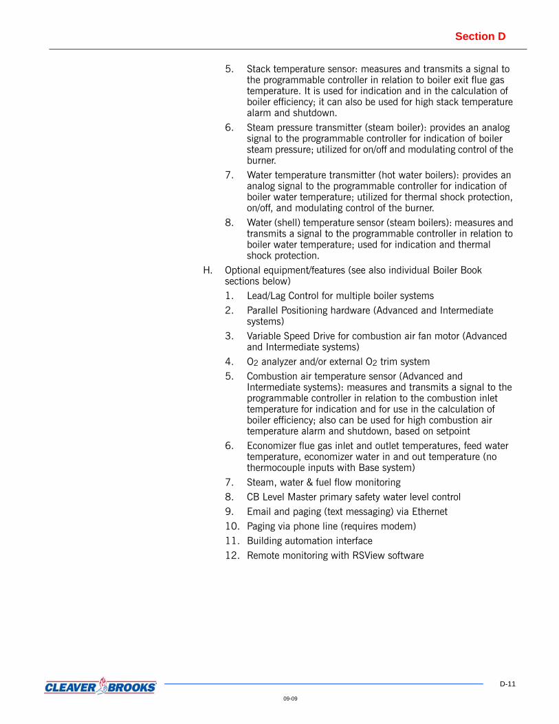
5. Stack temperature sensor: measures and transmits a signal to the programmable controller in relation to boiler exit flue gas temperature. It is used for indication and in the calculation of boiler efficiency; it can also be used for high stack temperature alarm and shutdown.
6. Steam pressure transmitter (steam boiler): provides an analog signal to the programmable controller for indication of boiler steam pressure; utilized for on/off and modulating control of the burner.
7. Water temperature transmitter (hot water boilers): provides an analog signal to the programmable controller for indication of boiler water temperature; utilized for thermal shock protection, on/off, and modulating control of the burner.
8. Water (shell) temperature sensor (steam boilers): measures and transmits a signal to the programmable controller in relation to boiler water temperature; used for indication and thermal shock protection.
H. Optional equipment/features (see also individual Boiler Book sections below)1. Lead/Lag Control for multiple boiler systems2. Parallel Positioning hardware (Advanced and Intermediate
systems)3. Variable Speed Drive for combustion air fan motor (Advanced
and Intermediate systems)4. O2 analyzer and/or external O2 trim system5. Combustion air temperature sensor (Advanced and
Intermediate systems): measures and transmits a signal to the programmable controller in relation to the combustion inlet temperature for indication and for use in the calculation of boiler efficiency; also can be used for high combustion air temperature alarm and shutdown, based on setpoint
6. Economizer flue gas inlet and outlet temperatures, feed water temperature, economizer water in and out temperature (no thermocouple inputs with Base system)
7. Steam, water & fuel flow monitoring8. CB Level Master primary safety water level control9. Email and paging (text messaging) via Ethernet10. Paging via phone line (requires modem)11. Building automation interface12. Remote monitoring with RSView software

Section D
D-12
09-09
Sample Specifications HAWK ICS Parallel Positioning System
PART 1 GENERAL The purpose of the parallel positioning system is to control fuel, combustion air andflue gas recirculation (FGR) if applicable. Individual actuators will be used to controleach of above functions.
PART 2 PRODUCTS
2.1 CONTROLLER - A/B COMPACT LOGIX PLC COMPRISING THE FOLLOWING COMPONENTS
Row 1
Processor L35E
SM2 Modbus ModulePower Supply 1769-PA4Discrete Input Module 1769-IA16Discrete Output Module 1769-OW8IAnalog Input Module 1769-IF4Analog Output Module 1769-OF2Themocouple input module 1769-IT6Discrete Input Module 1769-IA16Analog Input Module 1769-IF4Analog Output Module1769-OF2
Row 2
Power Supply 1769-PA2Analog Output Module 1769-OA16Analog Input Module 1769-IF4Analog Input Module 1769-IF4Expansion cable Right hand terminator
2.2 HMI (HUMAN MACHINE INTERFACE) 10” color PanelView touch screen with serial communication.
2.3 ACTUATORS Quantity up to 4.
Typical actuators arrangement:
Combustion airGasOilFGR

Section D
D-13
09-09
ACTUATOR SPECIFICATIONS
General: Reversing Motor with Position Feedback
Application: Control of Dampers and Fuel Valves
Note- Position will be controlled by a PLC; no Servo-Positioning Module is required.
Rotary: 90 Degree Rotation
30 Second Timing (for 90 Degrees)
36 in-lb Torque
0.1% Resolution (over 90 Degrees)
Electrical:
120 VAC Preferred
Control Signal: Pulse position with 0-10 VDC feedback
Duty: Continuous
Enclosure: NEMA 1 Minimum; NEMA 3 or 4 Optional
Approvals:
UL Listed or Recognized and/or FM Approved
Environmental: Temperature 0-130°F.
Whenever possible design without linkages shall be used.
Control Description
Control shall be parallel positioning with cross limiting.
Note: System will not be capable for simultaneous fuel firing.
Air control
Firing rate control signal is compared with corrected fuel actuator position signal.Highest of the two values is a control signal for the combustion air actuator. Velocitylimitter with adjustments in both directions (up and down) shall be provided.
Control signal to the actuator is compared with feedback signal. If unacceptableerror is detected for the preset amount of time, system will be shut down and faultwill be annunciated.
Fuel control
Firing rate control signal is compared with air actuator position signal. Lowest of thetwo values is an input to the function generator. Output of the function generator is acontrol signal for the fuel actuator. Function generator has to have a minimum of 10break points. The X-axis and Y-axis parameters must follow the relationship:
X[1] < X[2] < X[3] <... < X[n]
Y[1] < Y[2] < Y[3] < … < Y[n]
Where n is the number of break points (20 maximum).
Velocity limiter with adjustments in both directions (up and down) shall beprovided.

Section D
D-14
09-09
Control signal to the actuator is compared with feedback signal. If unacceptableerror is detected for the preset amount of time, system will be shut down and faultwill be annunciated.
FGR control
Firing rate control signal is compared with air actuator position signal. Lowest of thetwo values is an input to the function generator. Output of the function generator isa control signal for the FGR actuator. Function generator has to have a minimum of10 break points. The X-axis parameters must follow the relationship:
X[1] < X[2] < X[3] <... < X[n]
Where n is the number of break points (20 maximum).
Velocity limitter with adjustments in both directions (up and down) shall beprovided.
Control signal to the actuator is compared with feedback signal. If unacceptableerror is detected for the preset amount of time, system will be shut down and faultwill be annunciated.

Section D
D-15
09-09
CB-HAWK ICS COMBUSTION AIR FAN VARIABLE SPEED DRIVE
Provides variable speed output to the burner’s Combustion Air Fan blower motor forthe purpose of improving boiler efficiency and reducing electrical energyconsumption.
FEATURES AND BENEFITS
Improved Efficiency:
Energy Savings:
• Reduces electrical energy consumption
• Soft starting reduces electrical and mechanical stress on the motor, extending the life of the motor
• Provides Substantial Savings from Mid to Low Fire modulation points
• Average Payback in approximately 6 – 8 Months
Communication:
• Communicates with the Boiler Controller via Modbus
• Provides Drive process information on the Boiler Control Panel Display
• Provides Drive faults and troubleshooting suggestions, in “Plain English”, on Boiler Control Panel Display
PRODUCT OFFERING• Cleaver-Brooks shall supply the following equipment:
• Adjustable Frequency Variable Speed Drive.
• Modbus communications
• VSD Compatible Combustion Air Fan Motor.
Section D
D-16
09-09
ENGINEERING DATA
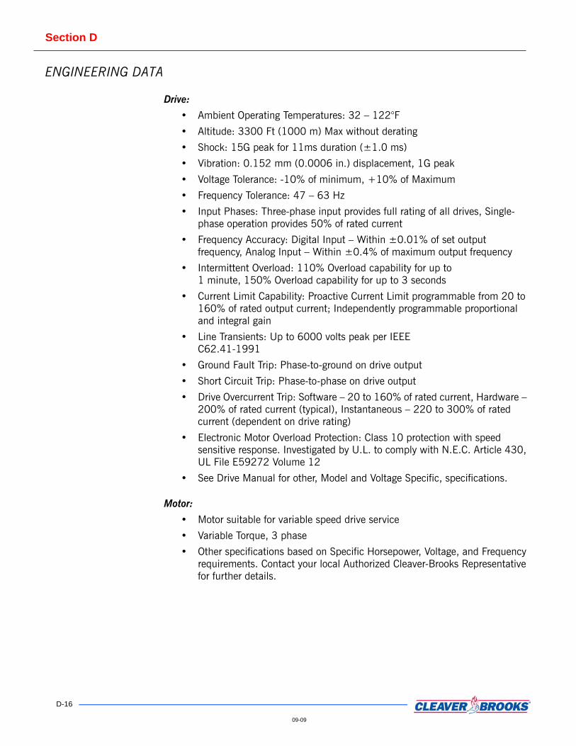
Drive:
• Ambient Operating Temperatures: 32 – 122°F
• Altitude: 3300 Ft (1000 m) Max without derating
• Shock: 15G peak for 11ms duration (±1.0 ms)
• Vibration: 0.152 mm (0.0006 in.) displacement, 1G peak
• Voltage Tolerance: -10% of minimum, +10% of Maximum
• Frequency Tolerance: 47 – 63 Hz
• Input Phases: Three-phase input provides full rating of all drives, Single-phase operation provides 50% of rated current
• Frequency Accuracy: Digital Input – Within ±0.01% of set output frequency, Analog Input – Within ±0.4% of maximum output frequency
• Intermittent Overload: 110% Overload capability for up to 1 minute, 150% Overload capability for up to 3 seconds
• Current Limit Capability: Proactive Current Limit programmable from 20 to 160% of rated output current; Independently programmable proportional and integral gain
• Line Transients: Up to 6000 volts peak per IEEE C62.41-1991
• Ground Fault Trip: Phase-to-ground on drive output
• Short Circuit Trip: Phase-to-phase on drive output
• Drive Overcurrent Trip: Software – 20 to 160% of rated current, Hardware – 200% of rated current (typical), Instantaneous – 220 to 300% of rated current (dependent on drive rating)
• Electronic Motor Overload Protection: Class 10 protection with speed sensitive response. Investigated by U.L. to comply with N.E.C. Article 430, UL File E59272 Volume 12
• See Drive Manual for other, Model and Voltage Specific, specifications.
Motor:
• Motor suitable for variable speed drive service
• Variable Torque, 3 phase
• Other specifications based on Specific Horsepower, Voltage, and Frequency requirements. Contact your local Authorized Cleaver-Brooks Representative for further details.

Section D
D-17
09-09
Sample SpecificationsCB-HAWK ICS Combustion Air Fan Variable
Speed Drive PART 1 GENERAL A. The Boiler Manufacturer shall provide a Variable Speed Drive
controller for use on the burner’s Combustion Air Fan blower motor for the purpose of providing Improved Boiler Efficiency and Reduced Electrical Energy consumption.
B. The Drive’s voltage, frequency, and current ratings shall be rated in accordance with the electrical requirements as dictated by job site specifics, and for the properly rated motor horsepower.
C. The Variable Speed Drive must be capable of communicating over the Modbus protocol.
D. A Motor suitable for variable speed drive service must be supplied for use in conjunction with the Variable Speed Drive, and sized to match the motor requirements of the Combustion Air Fan Blower.
E. Variable Speed Drive shall be interlocked with boiler control to ensure safe operation.
Section D
D-18
09-09
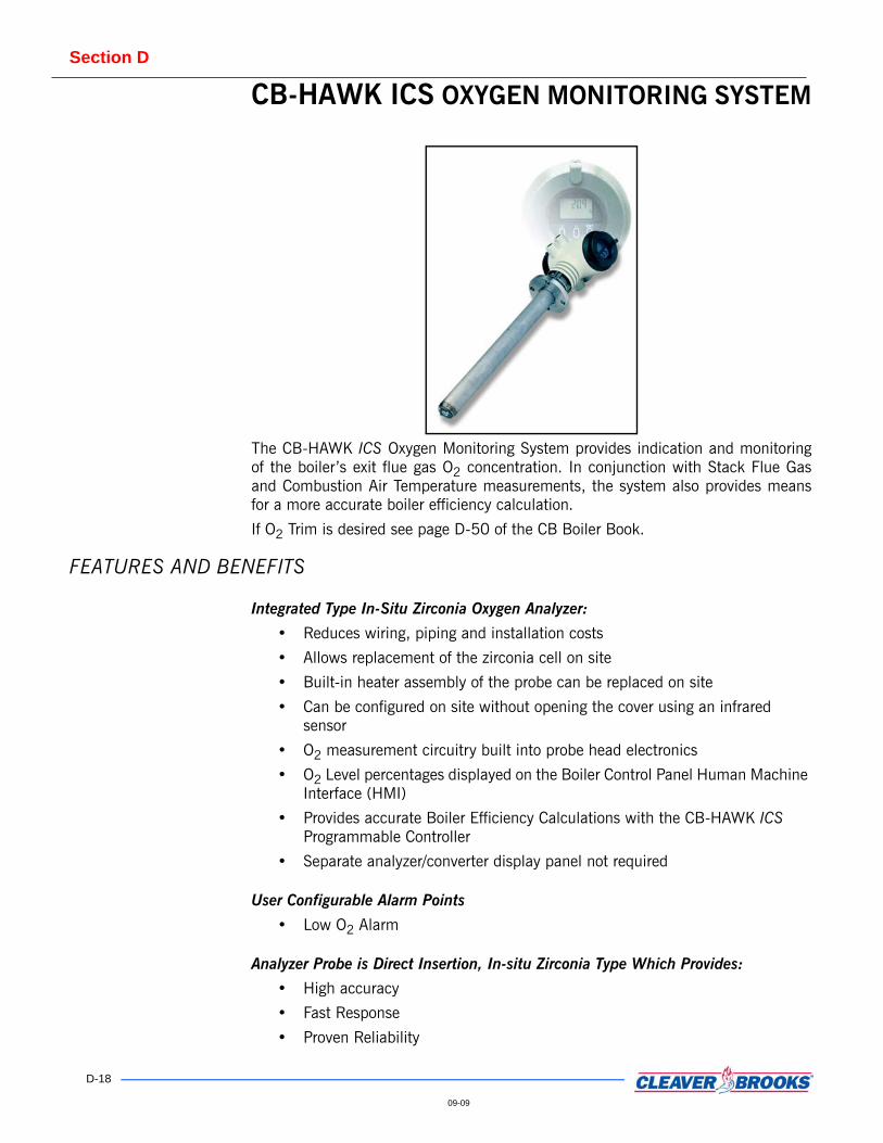
CB-HAWK ICS OXYGEN MONITORING SYSTEM
The CB-HAWK ICS Oxygen Monitoring System provides indication and monitoringof the boiler’s exit flue gas O2 concentration. In conjunction with Stack Flue Gasand Combustion Air Temperature measurements, the system also provides meansfor a more accurate boiler efficiency calculation.
If O2 Trim is desired see page D-50 of the CB Boiler Book.
FEATURES AND BENEFITS
Integrated Type In-Situ Zirconia Oxygen Analyzer:
• Reduces wiring, piping and installation costs
• Allows replacement of the zirconia cell on site
• Built-in heater assembly of the probe can be replaced on site
• Can be configured on site without opening the cover using an infrared sensor
• O2 measurement circuitry built into probe head electronics
• O2 Level percentages displayed on the Boiler Control Panel Human Machine Interface (HMI)
• Provides accurate Boiler Efficiency Calculations with the CB-HAWK ICS Programmable Controller
• Separate analyzer/converter display panel not required
User Configurable Alarm Points
• Low O2 Alarm
Analyzer Probe is Direct Insertion, In-situ Zirconia Type Which Provides:
• High accuracy
• Fast Response
• Proven Reliability

Section D
D-19
09-09
PRODUCT OFFERING• In-Situ Zirconia Probe and Analyzer
• Process Variable% O2 Readout on Control Panel HMI
• Accurate Efficiency Calculations
Options:
• Separate O2 Converter/Display Panel
• Replacement Zirconia Cell
• Auto Calibration Pneumatics
• Replacement Heater Assembly
• Remote Indicator/Alarm
• Probe Stack Mounting Adapter
• Calibration Gas Kit
ENGINEERING DATAAmbient Temperature: -4 to 131°F (-20 to +55°C)
Sample Gas Temperature: 32 to 1292°F (0 – 700°C)
Sample Gas Pressure: -1.5 to 73.8 in Hg (-5 to +250 kPa)
Output Signal: 4 – 20mA DC, One Point, Maximum Load Resistance 550 Ohms
Digital Output (HART): 250 – 500 Ohms
Contact Output Signal: Two Points, 30 VDC 3A, 250 VAC 3A (one is fail safe normally open)
Contact Input Signal: Two Points
Reference Air: Natural Convection, Instrument Air, pressure compensated
Instrument Air: 200 kPa plus the pressure in the furnace
Power Supply: 100 – 240 VAC, 50/60Hz
Power Consumption: Max 300 W, approx. 100 W for ordinary use
Sample SpecificationsCB-Hawk ICS Oxygen Monitoring System
PART 1 GENERAL A. This specification covers the hardware and monitoring functions of the CB-HAWK ICS Oxygen monitoring system. The system monitors and displays Oxygen concentration and is used, in conjunction with combustion air and stack flue gas temperature sensors, to calculate the overall efficiency of the boiler.
B. The system shall be completely configured from the factory requiring only job specific data to be entered (or modified) in the field.
Note: O2 Sensor Requires calibration in the field!

Section D
D-20
09-09
PART 2 PRODUCTS 2.1 HARDWAREA. Hardware shall consist of the following:
1. Oxygen Sensor2. Integrated type Zirconia Oxygen Analyzer3. Direct Insertion Type4. Built-in Heater Assembly5. 4-20mA DC Process Variable Output6. Heater to be of field replaceable construction7. Cell to be of field replaceable construction
B. Analyzer1. Shall be of the Integrated Type (in probe head)2. Provide 4 – 20mA DC Signal output in relation to process
variable for remote displayC. Monitoring System
1. Indicate O2 Percentages2. Provide Low O2 Alarm Indication3. Perform Efficiency Calculations and display results using
O2 percentages
PART 3 EXECUTION This system is applicable to modulating burners using the CB-HAWK ICS IntegratedControl System. This system shall monitor and display O2 concentration in theboiler’s exit flue gas and provide overall boiler efficiency calculations.

Section D
D-21
09-09
CB-HAWK ICS — ETHERNET COMMUNICATIONThe CB-HAWK ICS Ethernet communication package provides Ethernetcommunications between the CB-HAWK ICS programmable controller and otherEthernet compatible devices such as the Boiler Room Master Lead/Lag ControlPanel, Building/Plant automation system, and the Internet.
FEATURES AND BENEFITS • Provides communication between the CB-HAWK ICS programmable controller
unit and other Ethernet Compatible Devices
• Provides interface capability with many Building/Plant automation systemswhen utilizing OPC server or protocol bridge
• Provides interface with plants LAN/WAN
• Provides interface to the Internet (requires static IP address)
• E-mailing of boiler alarms/faults
• Provides means of connection between various boiler room control systems,such as the CB-HAWK ICS Master Panel for lead/lag control
• Provides means of connection to a remote Personal Computer
• Ethernet Industrial Protocol
• IEEE 802.3 Physical and Data Link Standard
• Ethernet TCP/IP protocol suite industry standard
• Control and Information Protocol (CIP) Compliant
PRODUCT OFFERING• Optional Ethernet Communication Hub (necessary for stand-alone boiler (no
Master Panel) connection to LAN/WAN and/or Paging Modem option)
• E-mail functionality — requires customer provided e-mail service and address
ENGINEERING DATA • Modular connection to CB-HAWK ICS Programmable Controller unit
• Ethernet Industrial Protocol (Allen-Bradley EPIC)
• Follows Ethernet Rules and Practices
• High Noise Rejection
• Cabling: Category 5E rated twisted pair cable (solid core, PVC jacket with RJ45connections).
• Meets Open Industrial Network Standards
• IEEE 802.3 Physical and Data Link Standard
• Ethernet TCP/IP protocol suite industry standard
• Control and Information Protocol (CIP) Compliant
• OPC (OLE Process Control) communication compatibility with RSLinx OPCServer software
Section D
D-22
09-09
Sample SpecificationsCB-HAWK ICS — Ethernet Communication
PART 1 GENERAL The Boiler Manufacturer shall furnish and install a control module capable of
Ethernet communications between the boiler’s programmable logic control systemand other Ethernet compatible devices, as needed, and provide the followingminimum requirements:
A. Interface with the Compact Logix Programmable Controller ProtocolB. Ethernet Industrial Protocol (Allen-Bradley EPIC)C. Follows Ethernet Rules and PracticesD. High Noise RejectionE. Open Industrial Network StandardsF. IEEE 802.3 Physical and Data Link StandardG. Ethernet TCP/IP protocol suite industry standardH. Control and Information Protocol (CIP) Compliant

Section D
D-23
09-09
CB-HAWK ICS — PAGING and REMOTE DIAL-UP ACCESS with MODEM
Provides Paging of Alarms Faults, via Modem, from the CB-HAWK ICS Control System to the customer provided pager or a compatible cell phone.
FEATURES AND BENEFITS • Paging of boiler system alarms. (Paging Service and Pagers furnished by
customer)
• Allows Remote Dial-Up Access for monitoring and troubleshooting.
PRODUCT OFFERING• Remote Access Paging Modem
• Easy to use configuration software
• Requires customer provided, dedicated phone line
• Requires customer provided Paging Service and pagers (or paging compatible cell phones)
• Requires Pager Numbers and PINs supplied by customer
• Configure up to 10 unique pagers
ENGINEERING DATA • Voltage: 24 VDC
• Baud Rate: 56K
• Type: External, Serial
• Paging functionality utilizes TAP Protocol
Sample Specifications CB-HAWK ICS — Paging and Remote Dial-up Access With Modem
PART 1 GENERAL The boiler manufacturer shall provide a Paging and Remote Dial-Up Access Modem,using customer provided paging systems for the purpose of paging boiler systemalarms and providing remote access to the control system.
Pager number(s) and PINs to be supplied by customer.
Dedicated telephone connection to be supplied by customer.
Section D
D-24
09-09
CB-HAWK ICS — LEAD/LAG FOR TWO BOILER SYSTEMS
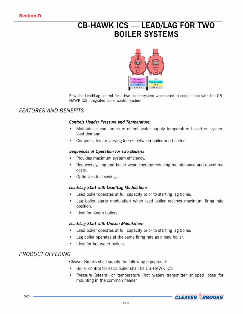
Provides Lead/Lag control for a two-boiler system when used in conjunction with the CB-HAWK ICS integrated boiler control system.
FEATURES AND BENEFITS
Controls Header Pressure and Temperature:
• Maintains steam pressure or hot water supply temperature based on systemload demand.
• Compensates for varying losses between boiler and header.
Sequences of Operation for Two Boilers:
• Provides maximum system efficiency.
• Reduces cycling and boiler wear; thereby reducing maintenance and downtimecosts.
• Optimizes fuel savings.
Lead/Lag Start with Lead/Lag Modulation:
• Lead boiler operates at full capacity prior to starting lag boiler.
• Lag boiler starts modulation when lead boiler reaches maximum firing rateposition.
• Ideal for steam boilers.
Lead/Lag Start with Unison Modulation:
• Lead boiler operates at full capacity prior to starting lag boiler.
• Lag boiler operates at the same firing rate as a lead boiler.
• Ideal for hot water boilers.
PRODUCT OFFERINGCleaver-Brooks shall supply the following equipment:
• Boiler control for each boiler shall be CB-HAWK ICS.
• Pressure (steam) or temperature (hot water) transmitter shipped loose formounting in the common header.
Section D
D-25
09-09
Sample Specifications CB-HAWK ICS — Lead/lag For Two-Boiler Systems
PART 1 GENERAL 1.1 GENERALA. Lead/Lag Start with either Lead/Lag or Unison Modulation.B. Boilers’ Start and Stop
1. Steam pressure, or hot water temperature, is compared with the setpoint and controller’s processor executes PID algorithm. Lead boiler is commanded to come on line first. Lag boiler is commanded to come on line when a firing rate signal for the lead boiler reaches lag boiler start point. Lag boiler is commanded to stop when a firing rate signal for the lag boiler reaches lag boiler stop point.
C. Lead/Lag Modulation - Lag boiler starts modulation after lead boiler reaches maximum firing rate.
D. Unison Modulation - Firing rates for both boilers are equal.E. Hot Standby - System shall have a provision for keeping lag boiler in
hot standby. Standby routine shall be based on a water temperature signal.
1.2 APPLICATION AND SYSTEM REQUIREMENTSA. This option is applicable to full modulation burners utilizing the CB-
HAWK ICS advanced boiler control system and modulating controls.B. All logic for Lead/Lag Control shall reside in the boiler controller. No
additional control panels shall be required.
Section D
D-26
09-09
CB-HAWK ICS — LEAD/LAG for up to EIGHT BOILERS SYSTEM
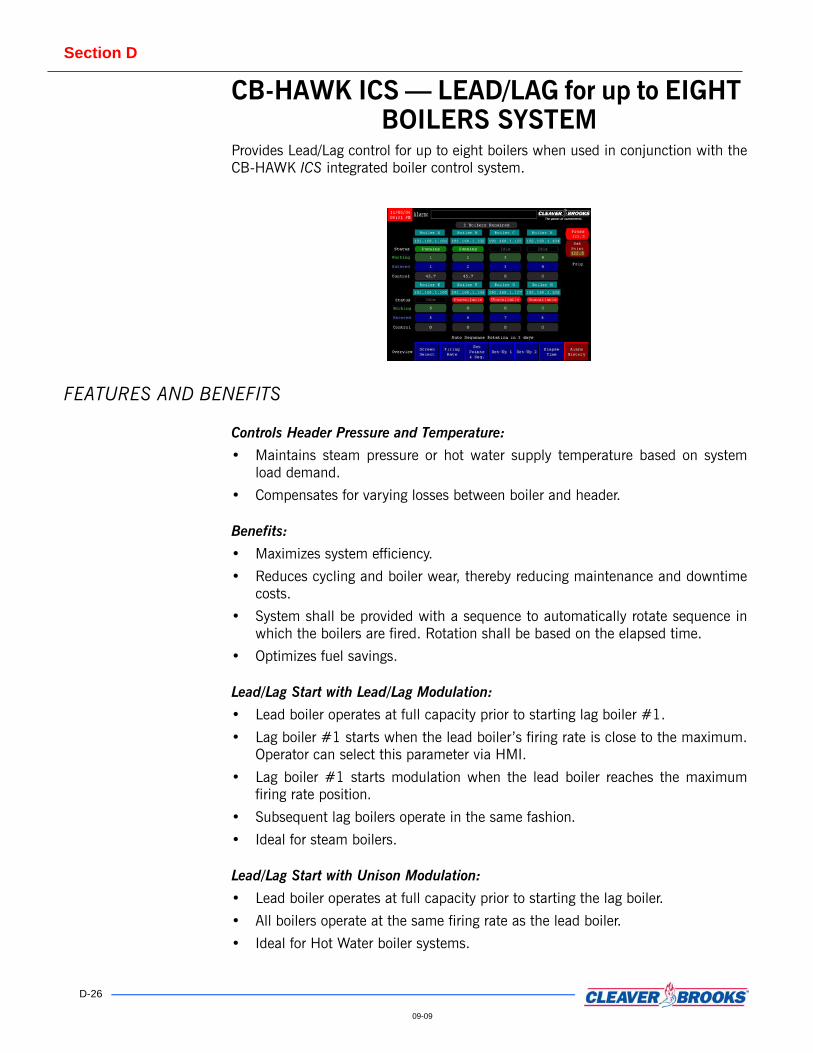
Provides Lead/Lag control for up to eight boilers when used in conjunction with theCB-HAWK ICS integrated boiler control system.
FEATURES AND BENEFITS
Controls Header Pressure and Temperature:
• Maintains steam pressure or hot water supply temperature based on systemload demand.
• Compensates for varying losses between boiler and header.
Benefits:
• Maximizes system efficiency.
• Reduces cycling and boiler wear, thereby reducing maintenance and downtimecosts.
• System shall be provided with a sequence to automatically rotate sequence inwhich the boilers are fired. Rotation shall be based on the elapsed time.
• Optimizes fuel savings.
Lead/Lag Start with Lead/Lag Modulation:
• Lead boiler operates at full capacity prior to starting lag boiler #1.
• Lag boiler #1 starts when the lead boiler’s firing rate is close to the maximum.Operator can select this parameter via HMI.
• Lag boiler #1 starts modulation when the lead boiler reaches the maximumfiring rate position.
• Subsequent lag boilers operate in the same fashion.
• Ideal for steam boilers.
Lead/Lag Start with Unison Modulation:
• Lead boiler operates at full capacity prior to starting the lag boiler.
• All boilers operate at the same firing rate as the lead boiler.
• Ideal for Hot Water boiler systems.

Section D
D-27
09-09
PRODUCT OFFERINGCleaver-Brooks shall supply the following equipment:
• Boiler control for each boiler shall be the CB-HAWK ICS.
• Pressure (Steam) or temperature (Hot Water) transmitter shipped loose for mounting in the common header.
• Master Control Panel shipped loose for field mounting.
• Requires Ethernet/IP Communication Option
Sample Specifications CB-HAWK ICS — Lead/lag for up to Eight Boilers System
PART 1 GENERAL 1.1 GENERALA. Lead/Lag Start with either Lead/Lag or Unison Modulation.B. Boilers’ Start and Stop
1. Steam pressure, or hot water temperature on hot water systems, is compared with the setpoint and controller’s processor executes PID algorithm. Lead boiler is commanded to come on-line first. Lag boiler #1 is commanded to come on-line when a firing rate signal for the lead boiler reaches lag boiler start point. Lag boiler #1 is commanded to stop when a firing rate signal for the lead boiler reaches lag boiler stop point.
2. Lag boiler #2 is commanded to come on-line when a firing rate signal for the lag boiler #1 reaches lag boiler #2 start point. Lag boiler #2 is commanded to stop when a firing rate signal for the lag boiler #1 reaches lag boiler #2 stop point.
3. Subsequent boilers operate in a similar fashion.C. Lead/Lag Modulation
1. Lag boiler #1 starts modulation after lead boiler reaches maximum firing rate (or firing rate selected by the operator).
2. Lag boiler #2 starts modulation after lag boiler #1 reaches maximum firing rate (or firing rate selected by the operator).
3. Subsequent boilers operate in a similar fashion.D. Unison Modulation - Firing rates for all boilers are equal.E. Hot Standby - System shall have a provision for keeping lag boilers
in hot standby. Standby routine shall be based on a water temperature signal.
F. Firing Sequence Selection - Sequence in which boilers come on-line shall be selected via HMI. Adequate check shall be provided that does not allow improper sequence selection.
G. Automatic Rotation of the Boilers - System shall be provided with a sequence to automatically rotate sequence in which the boilers are fired. Rotation shall be based on the elapsed time.

Section D
D-28
09-09
1.2 HMI (HUMAN MACHINE INTERFACE)A. Master panel shall include HMI for display and selection of the
following parameters:B. Display
1. Available boilers2. Number of boilers required3. Selected sequence of firing4. Control output to each boiler5. Header steam pressure or water temperature on hot water
systems6. Setpoint7. Elapsed time from last rotation
C. Selection1. Number of boilers 2. Sequence of firing3. Automatic or manual rotation4. Individual boiler start and stop points with timers5. Setpoint6. Proportional, integral and derivative gains for control algorithm
1.3 APPLICATION AND SYSTEM REQUIREMENTSA. This option is applicable to full modulation burners utilizing the CB-
HAWK ICS advanced boiler control system and modulating controls.B. Logic for Lead/Lag control shall reside in the Master Control Panel.
Communication between the Master Panel and the individual Boiler Control Panels shall be via Ethernet communication or hard wiring.
Section D
D-29
09-09
CB780E CONTROL
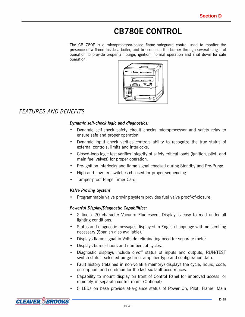
The CB 780E is a microprocessor-based flame safeguard control used to monitor thepresence of a flame inside a boiler, and to sequence the burner through several stages ofoperation to provide proper air purge, ignition, normal operation and shut down for safeoperation.
FEATURES AND BENEFITS
Dynamic self-check logic and diagnostics:
• Dynamic self-check safety circuit checks microprocessor and safety relay toensure safe and proper operation.
• Dynamic input check verifies controls ability to recognize the true status ofexternal controls, limits and interlocks.
• Closed-loop logic test verifies integrity of safety critical loads (ignition, pilot, andmain fuel valves) for proper operation.
• Pre-ignition interlocks and flame signal checked during Standby and Pre-Purge.
• High and Low fire switches checked for proper sequencing.
• Tamper-proof Purge Timer Card.
Valve Proving System
• Programmable valve proving system provides fuel valve proof-of-closure.
Powerful Display/Diagnostic Capabilities:
• 2 line x 20 character Vacuum Fluorescent Display is easy to read under alllighting conditions.
• Status and diagnostic messages displayed in English Language with no scrollingnecessary (Spanish also available).
• Displays flame signal in Volts dc, eliminating need for separate meter.
• Displays burner hours and numbers of cycles.
• Diagnostic displays include on/off status of inputs and outputs, RUN/TESTswitch status, selected purge time, amplifier type and configuration data.
• Fault history (retained in non-volatile memory) displays the cycle, hours, code,description, and condition for the last six fault occurrences.
• Capability to mount display on front of Control Panel for improved access, orremotely, in separate control room. (Optional)
• 5 LEDs on base provide at-a-glance status of Power On, Pilot, Flame, Main

Section D
D-30
09-09
Valves, and Alarm conditions (Power LED blinks periodically to indicate propercontrol operation).
• Diagnostic display capabilities are further enhanced by the optional CB783Expanded Annunciator which provides 36 additional specific HOLD and Faultmessages, as well as 26 LEDs to indicate current status or first-out alarmindication (user-selectable).
• Communication capabilities to a local or remote Personal Computer, withoptional CB-LINKcommunications module and Combustion System Manager™software (runs under Microsoft Windows®).
Application Flexibility:
• Purge Timing Cards available in 30, 60, 90 seconds or 2-1/2 minutes cover awide range of applications, while eliminating need for a separate purge timer.
• Separate output for ignition transformer simplifies applications requiring earlyspark termination.
• Selectable configuration jumpers allow application-specific configuration.
• Communication interface capability.
Simplified Servicing:
• Diagnostic and fault history information available through display simplifiestroubleshooting procedures.
• Removable access covers for checking voltage at terminals.
• 5-function RUN/TEST switch eases start-up procedure.
• Flame signal display facilitates pilot/light-off test procedures.
PRODUCT OFFERING
Included in each CB 780E system is the following:
• One CB780E chassis, including display module.
• One Purge Timer Card.
• One wiring sub-base.
• One flame scanner, either Infrared, Ultra-Violet, or UV Self-Check.
• One flame amplifier, to correspond with the selected flame scanner.
Included with the optional CB783 Expanded Annunciator:
• One CB783 Annunciator.
• One wiring sub-base.
• All limits and interlocks are wired into wiring sub-base to provide individualhold/fault indication on LEDs of Expanded Annunciator, as well as on displaymodule of CB 780E control.
ENGINEERING DATA• Supply voltage: 120 Vac (+10%/-15%) 50 or 60 Hz.
• Maximum total load: 2000 VA.
Section D
D-31
09-09
• Load rating-fuel valve output: 65 VA pilot duty plus 1150 VA inrush, 460 VAopening, 250 VA holding.
• Operating temperature limits: -40 to 140 °F.
• Maximum ambient humidity: 85% non-condensing.
Sample SpecificationCB780E Control
PART 1 GENERAL Flame safeguard shall be a Cleaver-Brooks Model CB 780E microprocessor-basedcontrol to monitor all critical boiler and burner interlocks, control and superviseburner light off sequence, and initiate an orderly safety procedure in the event ofinterlock or flame failure. The system shall provide status, fault history, anddiagnostic information by means of a two-line alpha-numeric display and alarm/status LEDs. The system shall be approved by UL, FM, and CSA, and shall beacceptable by IRI.

Section D
D-32
09-09
CB120/120E CONTROLSThe CB120 is a microprocessor-based burner management control system designedto provide the proper burner sequencing, ignition, and flame monitoring protectionon automatically ignited oil, gas , and combination fuel burners. In conjunction withlimit and operating controls, it programs the burner/blower motor, ignition, and fuelvalves to provide for proper and safe burner operation
The CB120E includes all of the features of the CB120 with the addition of analphanumeric display.
FEATURES AND BENEFITS
Display and Diagnostic Capabilities:
• (CB120E) 2 x 16 character display with keypad. Available display types arevacuum fluorescent (VFD) and liquid crystal (LCD). VFD has increasedbrightness and extended operating temperature range to -40°F. Messages arespelled out in English (optional Spanish version is also available). Providesindication of flame signal during operation.
• Lockout history stores last 10 lockouts with burner cycle and burner hour whenoccurred.
• Display module can be mounted remotely from the CB120 for externalindication (optional).
• Optional expanded annunciator provides increased messaging and diagnosticcapabilities.
• Optional communication via Modbus with local or remote PC.
Modular Design:
• Interchangeable program modules in English or Spanish.
• Adjustable purge time programmable via display.
• Chassis available for infrared, ultra-violet, or UV self-check flame scanners.
• Reduces part replacement costs.
Section D
D-33
09-09
PRODUCT OFFERING
Included in each CB120 System is the following:
• Chassis with corresponding flame ampliifier
• Plug-In Programmer Module.
• Wiring base.
• Flame scanner - either infrared, ultra-violet, or UV self-check.
Included in each CB120E System is the following:
• All of the above
• Alphanumeric display
Display is required for Modbus communication or to access special functions.
ENGINEERING DATA • Supply voltage: 120 Vac (+10%/-15%) 50/60 Hz.
• Fuel valve output load rating: 65 VA pilot duty plus 3850 VA inrush, 700 VAopen, 250 VA hold.
• Operating temperature limits: -40°C (-40°F) to 60°C (140 °F). LCD display min.temp. limit -20°C (-4°F).
• Maximum ambient humidity: 90% non-condensing.
Sample Specification CB120/120E Control
PART 1 GENERAL Flame safeguard shall be a Cleaver-Brooks Model CB120/120E microprocessor-based control to monitor all critical boiler and burner interlocks, control andsupervise burner light-off sequence, and initiate an orderly safety procedure in theevent of interlock or flame failure. CB120E system shall provide status, fault history,and diagnostic information by means of a 2 x 16 VFD or LCD display. The systemshall be approved by UL, FM, and CSA, and shall be acceptable by IRI.
Section D
D-34
09-09
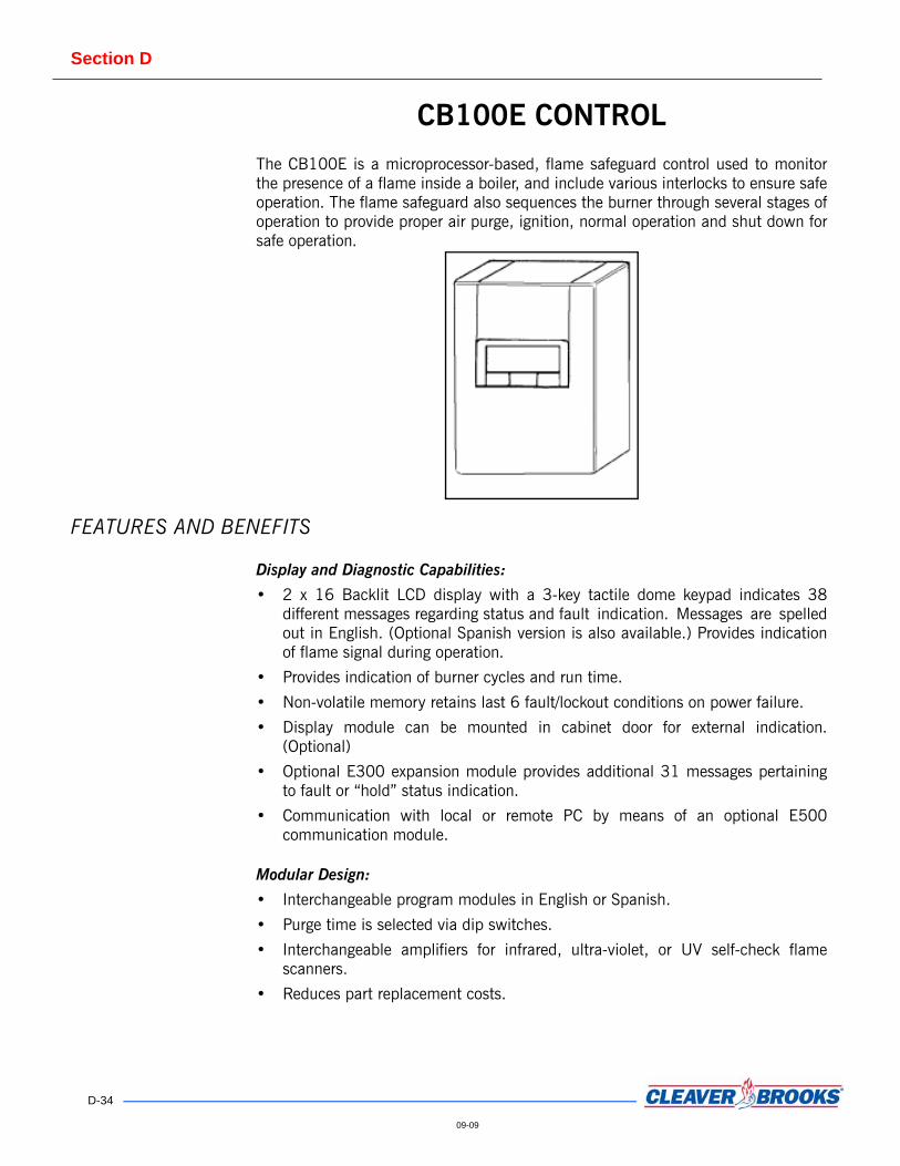
CB100E CONTROLThe CB100E is a microprocessor-based, flame safeguard control used to monitorthe presence of a flame inside a boiler, and include various interlocks to ensure safeoperation. The flame safeguard also sequences the burner through several stages ofoperation to provide proper air purge, ignition, normal operation and shut down forsafe operation.
FEATURES AND BENEFITS
Display and Diagnostic Capabilities:
• 2 x 16 Backlit LCD display with a 3-key tactile dome keypad indicates 38different messages regarding status and fault indication. Messages are spelledout in English. (Optional Spanish version is also available.) Provides indicationof flame signal during operation.
• Provides indication of burner cycles and run time.
• Non-volatile memory retains last 6 fault/lockout conditions on power failure.
• Display module can be mounted in cabinet door for external indication.(Optional)
• Optional E300 expansion module provides additional 31 messages pertainingto fault or “hold” status indication.
• Communication with local or remote PC by means of an optional E500communication module.
Modular Design:
• Interchangeable program modules in English or Spanish.
• Purge time is selected via dip switches.
• Interchangeable amplifiers for infrared, ultra-violet, or UV self-check flamescanners.
• Reduces part replacement costs.

Section D
D-35
09-09
PRODUCT OFFERING
Included in each CB100E System is the following:
• One chassis, including a dust cover.
• One 2-line display module.
• One Programmer Module.
• One wiring sub-base.
• One flame scanner, either infrared, ultra-violet, or UV self-check.
• One flame amplifier — to correspond with the selected flame scanner.
Included with optional E300 Expansion Module is:
• One E300 expansion module.
• One wiring subbase.
• One interconnection cable to E100E.
• All interlocks are wired into wiring sub base to provide individual hold/faultindication on display of CB100E control.
ENGINEERING DATA • Supply voltage: 120 Vac (+10%/-15%) 50/60 Hz.
• Maximum total load: 2000 VA.
• Fuel valve output load rating: 1250 VA opening, 500 VA holding.
• Operating temperature limits:32 °F to 125 °F.
• Maximum ambient humidity: 85% non-condensing.
Sample Specification CB100E Control
PART 1 GENERAL Flame safeguard shall be a Cleaver-Brooks Model CB100E microprocessor-basedcontrol to monitor all critical boiler and burner interlocks, control and superviseburner light-off sequence, and initiate an orderly safety procedure in the event ofinterlock or flame failure. The system shall provide status, fault history, anddiagnostic information by means of a 2 x 16 backlit LCD display. The system shallbe approved by UL, FM, and CSA, and shall be acceptable by IRI.

Section D
D-36
09-09
CB110 CONTROL
The CB 110 is a micro-processor-based, flame safeguard control used to monitorthe presence of a flame inside a boiler, and include various interlocks to ensure safeoperation. The flame safeguard also sequences the burner through several stages ofoperation to provide proper air purge, ignition, normal operation and shut down forsafe operation.
FEATURES AND BENEFITS
Self Diagnostics:
• Seven LED display provided to indicate: Fan, High Fire, Low Fire, Ignition,Flame detected, Auto and Alarm.
• 23 Fault indications.
Modular Design:
• Interchangeable amplifiers for infrared, ultra violet, or UV self-check flamescanners.
• Reduces part replacement costs.
• Easily upgradeable to a CB 100E by replacing programmer and displaymodules.
PRODUCT OFFERING
Included in each CB 110 System is the following:
• One CB 110 chassis, including dust cover.
• One Programmer/Display Module.
• One wiring subbase.
• One flame scanner, either infrared, ultra-violet, or UV self-check.

Section D
D-37
09-09
• One flame amplifier — to correspond with the selected flame scanner.
ENGINEERING DATA• Supply voltage: 120Vac (+10%/-15%) 50/60 Hz.
• Maximum total load: 2000 VA.
• Fuel valve output load rating: 1250 VA opening, 500 VA holding.
• Operating temperature limits: -40 °F to 125 °F
• Maximum ambient humidity: 85% non-condensing.
Sample SpecificationCB110 CONTROL
PART 1 GENERAL Flame safeguard shall be a Cleaver-Brooks Model CB 110 microprocessor-based control to monitor all critical boiler and burner interlocks, control and supervise burner light-off sequence, and initiate an orderly safety procedure in the event of interlock or flame failure. The system shall provide status, fault history, and diagnostic information by means of an LED display. The system shall be approved by UL, FM, and CSA, and shall be acceptable by IRI.

Section D
D-38
09-09
LEAD/LAG SYSTEMS (TWO BOILER LEAD/LAG)
This section contains information on Multiple Boiler Lead/Lag systems. For Lead/Lag systems used with boilers equipped with the CB-HAWK ICS system, refer to theCB-HAWK ICS Two Boiler Lead/Lag and Eight Boiler Lead/Lag sections.
FEATURES AND BENEFITS
Controls Actual Header Pressure and Temperature:
• Maintains steam or hot water supply to system load.
• Compensates for varying losses between boiler and header.
Sequences Operation of Two Boilers:
• Maximum system efficiency.
• Reduces cycling and boiler wear reducing maintenance and downtime costs.
• Optimizes fuel savings.
Lead/Lag Start with either Lead/Lag Modulation or Lead/Lag High-Low Fire:
• Lead boiler operates at full capacity prior to starting lag boiler.
• Ideal where load swings are infrequent and small such as heating applications.
Lead/Lag Start with either Unison Modulation or Unison High-Low Fire:
• Boilers operate in unison when both are on line.
• Ideal where load swings are frequent and large, such as process applications.
PRODUCT OFFERING Cleaver-Brooks shall supply the following equipment:
• Lead/Lag selector switch mounted on one boiler.
• On-off and firing rate controls shipped loose for mounting in common header piping.
• Minimum temperature low-fire-hold control — steam boilers.
• Low-fire-hold control — hot water boilers.
• Components shall be Underwriters Laboratories’ approved for intended service.
Section D
D-39
09-09
Sample Specifications Lead/Lag Systems (Two-boiler Lead/lag)
PART 1 GENERAL 1.1 GENERALA. Lead/Lag Start with either Lead/Lag Modulation or Lead/Lag High-
Low Fire. B. The boiler manufacturer shall supply a control system to lead and
lag two boilers. The system shall start, stop, and control the firing rate of both boilers.
C. Upon system demand, the lead boiler shall start and operate to full capacity prior to starting the lag boiler. When both boilers are on line, the lead shall always operate to full capacity and the lag shall operate between minimum and maximum output to satisfy demand requirements.
D. When system demand decreases, the lag boiler shall return to the minimum firing rate position and shut off. A further decrease shall cause the lead boiler to reduce its firing rate to minimum and shut off.
E. A switch shall be provided to rotate the lead position between both boilers.
F. For steam boilers, a means shall be provided to maintain minimum boiler water temperature at low-fire when the boilers are off line.
G. For hot water boilers, a means shall be provided to keep the boilers at low-fire rate until a predetermined minimum temperature is reached. This releases the boiler to automatic operation from the firing rate control.
H. All components shall be Underwriters Laboratories approved for intended service.
I. Lead/Lag Start with either Unison Modulation or Unison High-Low-Fire.
J. The boiler manufacturer shall supply a control system to lead and lag start of two boilers. The system shall start, stop, and control the firing rate of both boilers.
K. Upon system demand, the lead boiler shall start and operate to full capacity prior to starting the lag boiler. When both boilers are on line, they shall operate in unison between minimum and maximum output to satisfy demand requirements.
L. When system demand decreases, both boilers shall reduce their firing rate, in unison, to minimum. The lag boiler shall shut off and the lead boiler shall operate between minimum and maximum until demand is satisfied, and then shut off. A switch shall be provided to rotate the lead position between both boilers.
M. For steam boilers, means shall be provided to maintain minimum boiler water temperature at low-fire when boilers are off line.
N. For hot water boilers, means shall be provided to keep boilers in a low-fire-hold mode until a predetermined minimum temperature is reached. This shall then release the boiler to automatic operation from firing rate control.

Section D
D-40
09-09
O. All components shall be Underwriters Laboratories approved for intended service.
P. The lead/lag system is a specialized digital control that sequences the starting, stopping, and controls modulation firing rate for two boilers. It can be used for either steam or hot water applications.
1.2 APPLICATIONThis option is applicable to full modulation burners utilizing standard Cleaver-Brooks modu-lating controls.

Section D
D-41
09-09
LEAD/LAG SYSTEMS (TWO THROUGH FOUR BOILER LEAD/LAG)
The lead-lag system is a specialized digital control that sequences the starting,stopping, and controls modulation firing rate for two through four boilers. It can beused for either steam or hot water applications.
FEATURES AND BENEFITS
PID Control Logic:
• Precise control.
• Monitors rate of change to anticipate needs of system, turning boilers on or offas needed.
Lead/Lag Start and Modulation:
• Provides optimal control action for different applications.
• Lead boiler rotates automatically every 24 hours or manually selected for fixedlead position.
Boilers Controlled From Header Pressure or Temperature:
• Maintain constant steam or hot water supply to system load.
• Compensate for varying losses between boiler and header.
Sequences Optimal Number of Boilers on Line:
• Maximum system efficiency.
• Reduces cycling and boiler wear reducing maintenance and downtime costs.
• Optimizes fuel savings.
PRODUCT OFFERING Cleaver-Brooks shall supply the following equipment:
• Lead/lag sequencing control system for full modulating boilers (four boilersmaximum).
• Relays on control system panel for start-stop control of boilers.
• Pressure or temperature sensor and immersion well.
• Assured low-fire cutoff upon boiler shut off (steam and hot water boilers).
• Minimum temperature low-fire-hold control (steam boilers).
• Low-fire-hold control (hot water boilers).

Section D
D-42
09-09
ENGINEERING DATA Voltage input: 115 V, 60 Hz
Power consumption: 30 VA maximum
Output rating:
Relays: 1 amp inductive, 10 amp resistive at 115 V, 60 Hz. (up to 4 relays used,plug in type).
• Firing rate signal: 0 to 135 ohm resistive.
• Sensor ranges:
• Temperature: -30 °F to 250 °F accuracy plus or minimum 1°F.
• Pressure: 0-30 psig, 0-100 psig, 0-200 psig accuracy 1% full scale.
Standby battery: Operates for 100 days minimum with overall average life of 5years.
Maximum ambient temperature: 120 °F.
Sample Specifications Lead/lag Systems (Two Through Four Boiler Lead/lag)
PART 1 GENERAL 1.1 GENERALA. The boiler manufacturer shall furnish a microprocessor based
control system. The control shall be engineered and programmed exclusively for the operation of multiple steam or hot water full modulation boilers. It shall incorporate the following integrated functions: 1. Manual or automatic lead stage rotation; boiler sequencing and
burner firing rate (modulation control). The control shall be of modular construction to facilitate field modification, upgrading or repair. It shall include the following features.
B. The control shall have the capability of operating in a temperature or pressure mode. Temperature sensors shall be of the thermistor type, suitable for insertion into a 3/8” ID well. Standard operating range shall be -30 °F to +250 °F. Pressure sensors shall be of the 4-20 ma type. Standard operating range shall be 0-30, 0-100, 0-150 or 0-200 psig.
C. The control shall provide an integral sensor set point adjustment. The set point shall be adjustable in 1 °F or 1 psig increments (1/10 psig increments for 0-30 psig units) via a multi-turn knob. The setting value shall be stored in EEPROM indefinitely.
D. The control shall provide a LED bar graph display of each boiler’s approximate percent modulation. The control shall also provide a digital LED display of actual temperature or pressure, set point temperature or pressure, gain adjustment and each boilers exact percent modulation. In addition, the digital display shall be used to indicate the following four control settings as they are being adjusted: 1. Modulation start point shall be adjustable from 50 to 100%.
This setting determines the percent modulation a stage must achieve before the next stage is activated. There shall be

Section D
D-43
09-09
independent adjustment of this setting for each burner. 2. Purge timer shall be adjustable from 0-9.9 minutes. This
setting determines the delay time between a burner being started and the beginning of modulation.
3. Set back (additional set point) shall be adjustable from 0-75 °F/psig (0-7.5 psig on 0-30 psig units). This setting determines the °F/psig drop from the primary set point whenever the setback mode is activated. An “off” setting shall also be included for complete burner shutdown. The set back mode shall be activated by an external switch closure.
4. Standby timer shall be adjustable from 1-60 minutes. This setting determines the delay period which must elapse before any designated standby boilers are activated. The timing sequence shall begin when all active boilers reach 100% firing rate.
E. LEDs shall be provided to indicate the lead stage and all activated stages.
F. A lithium “coin” type battery shall be included to maintain the correct lead stage and lead stage rotation timer in the event of power failure. Storage capacity shall be 100 days.
G. A four position selector switch shall be provided to set the operating mode of each stage. Positions include on, auto, off and standby.
H. The control shall have the capability of operating up to four full modulation boilers. Each stage shall have the following outputs: 1. A normally open contact to start/stop the burner. 2. A 0-135 ohm output to independently control each burner’s
firing rate. I. The control shall be UL listed, tested per Standard 873.
Temperature Indicating and Regulating Equipment. It shall be CSA listed, tested per Standard C22.2 Number 24-1987 Temperature Indicating and Regulating Equipment. It shall also be approved for use in NYC by the City of New York; Department of Buildings, Bureau of Electrical Control and Department of Environmental Protection, Bureau of Air Resources.
J. A surface mounted, locking steel, NEMA 1 type, minimum 18 gauge enclosure shall be provided.
1.2 APPLICATIONThis option is applicable to full modulation burners utilizing standard Cleaver-Brooksmodulating controls.

Section D
D-44
09-09
LOW FIRE HOLD CONTROLFEATURES AND BENEFITS
Prevents Automatic Control of Burner Firing Rate Until Pre- Determined Boiler Water Temperature is Reached:
• Equalizes water temperature in boiler.
• Reduces possibility of thermal shock to pressure vessel and refractory.
PRODUCT OFFERING Cleaver-Brooks shall provide a boiler water temperature control with sensor andimmersion well. The control is Underwriters Laboratories approved for intendedservice and shall be mounted and wired on the boiler.
RECOMMENDED USEThe use of this control is recommended where a minimum temperature control hasnot been installed and where operating personnel may not be diligent in manuallyplacing the boiler at low fire until the boiler shell is of equal temperaturethroughout.
Note: In an emergency one can override this control by placing the “Manual-Auto” switch in the Manual position.
Sample Specifications Low Fire Hold Control
PART 1 GENERAL 1.1 GENERALThe boiler manufacturer shall furnish and install a control to sense boiler watertemperature. The control shall maintain burner in a low-fire hold mode until a pre-set temperature is satisfied. This shall then release boiler to automatic control ofsystem demand. Control shall be Underwriters Laboratories approved for intendedservice.
1.2 APPLICATIONThis option is applicable to full modulation and high-low fire burners.
BB_D-03-06
Section D
D-45
09-09
MINIMUM TEMPERATURE — LOW FIRE HOLD CONTROL
FEATURES AND BENEFITS
Maintains Minimum Boiler Water Temperature in Steam Boilers at Low-Fire Mode of Operation During Off Periods:
• Reduces lag-time to steaming rate.
• Reduces possibility of thermal shock to pressure vessel and refractory.
• Operational mode-manual or automatic.
PRODUCT OFFERING Cleaver-Brooks shall supply:
• Boiler water temperature control and immersion well.
• Interface relay.
• Operation mode.
• Manual — selector switch.
• Automatic — activated by remote on-off boiler control device.
• Components Underwriters Laboratories’ approved for intended service.
RECOMMENDED USEA common procedure at many steam boiler installations is to shut the boiler offovernight, during weekends, or during holidays. During this “off” period boiler watertemperature decreases. This can effectively decrease boiler metal and refractorytemperatures to near room temperature. After this “off” period the boiler is placedback into operation. Due to low boiler water temperature and a steam pressuredemand the boiler will immediately position itself at high fire. The important factorsto remember are that metals expand when heated; contract when cooled. This isalso true of boiler refractory. With repeated heating and cooling of any boiler,premature deterioration of boiler refractory, metals, and resultant tube leakage canoccur. To minimize these effects, the installation of a combination minimumtemperature-low fire hold control is recommended.
Occasionally there are objections to the use of a combination minimumtemperature-low fire hold control. If the “off” period will be of prolonged durationmaintaining minimum temperature could represent a considerable waste of fuel.Under this condition it is recommended that a low fire hold control be installed.
06-08

Section D
D-46
09-09
Sample Specifications Minimum Temperature — Low Fire Hold Control
PART 1 GENERAL 1.1 GENERALThe boiler manufacturer shall furnish and install a control to sense boiler watertemperature. The control shall have an adjustable set point to maintain a minimumtemperature at a pre-set level when the boiler is off line. This shall be accomplishedat the burners minimum firing rate. The function can be activated either manuallyor automatically. Components shall be Underwriters Laboratories approved forintended service.
1.2 APPLICATIONThis option is applicable to full modulation and high-low fire burners.

Section D
D-47
09-09
ASSURED LOW FIRE CUTOFFFEATURES AND BENEFITS
Assures that the burner shuts off at minimum firing rate when signaled from remote disable source:
• Prevents shutoff at firing rates above low fire.
• Reduces possibility of thermal shock to pressure vessel and refractory.
PRODUCT OFFERING Cleaver-Brooks shall provide terminal connection points for remote disable/enablesignals, and internally wire additional electrical components necessary to performthis function.
Sample Specifications Assured Low Fire Cutoff
PART 1 GENERAL 1.1 GENERALThe boiler manufacturer shall make provisions to accept remote enable/disablesignal contact. Any disable signal shall cause the burner to return to minimum lowfire position prior to shutting off the main fuel.
1.2 APPLICATIONThis option is applicable to full modulation and high-low fire burners.

Section D
D-48
09-09
REMOTE MODULATIONFEATURES AND BENEFITS
• Provides burner modulation from a customer supplied 4-20 ma control signal.
• Ties boiler firing rate control with customer control system (for example,building management, boiler room master, lead-lag control).
PRODUCT OFFERING
Standard Equipment
• Resistor kit to allow standard firing rate motor to operate from a 4-20 macontrol signal.
• Relay with gold flashed contacts to switch between automatic and manualoperation.
• Manual firing rate potentiometer to allow local manual operation.
Optional Equipment
Local — remote firing rate control selector switch.
• Allows control of firing rate from standard local firing rate controller or remote 4-20 ma signal.
Sample SpecificationRemote Modulation
1.1 GENERALFurnish and install components to allow burner to modulate from a remote 4-20 macontrol signal. Provisions shall be made for local manual firing rate control.
1.2 APPLICATIONThis option is applicable to full modulation burners utilizing standard Cleaver-Brooks modulating controls.
Section D
D-49
09-09
AUTOMATIC FUEL CHANGEOVERFEATURES AND BENEFITS
• Provides sequence to allow burner to automatically change fuel.
• Interfaces boiler-burner control with customer control system and avoidspremium charges for fuel.
PRODUCT OFFERING• A selector switch. With selector switch in the “AUTO” position, burner shall fire
primary fuel when auxiliary contact governing fuel selection (for an example, gaspressure switch or outdoor thermostat) is closed. Upon opening of the abovecontact: a burner shall modulate to the minimum firing rate position, shutdownand restart firing stand by fuel.
• Fuel auto changeover switch (a low gas pressure switch or outdoor thermostat).This switch may be furnished by the boiler supplier, customer, or utility.
Sample SpecificationAutomatic Fuel Changeover
PART 1 GENERAL 1.1 GENERALThe boiler manufacturer shall furnish sequence to allow an automatic changeoverfrom primary to stand by fuel and back. An automatic fuel changeover shall beinitiated by gas pressure, outdoor temperature or other dry contact.
1.2 APPLICATIONThis option is applicable to dual-fuel (i.e., gas-oil fired) boilers with exception ofModel LE Boilers.

Section D
D-50
09-09
Accu-Trim O2TRIM SYSTEMThe C-B Accu-Trim O2 Trim System is a stand-alone PLC-based control systemdesigned to maintain the proper fuel-air ratio of a boiler/burner. The system willautomatically compensate for changes in temperature, barometric pressure, or fuelcharacteristics, as well as correcting for normal hystereses. The system is intendedfor use on a Cleaver-Brooks boiler or burner with single point positioning, orjackshaft-type, combustion controls; however, it may be customized for specialapplications such as parallel positioning or alternate fuel firing. A complete systemincludes oxygen and firing rate sensors, a control panel which houses the PLC, andan actuator or VSD system which trims either the fuel or air flow.
FEATURES AND BENEFITS • Single unit PLC / HMI with 6” color touchscreen
• Modular DIN rail mounted I/O - 8 analog inputs, 8 analog outputs, 4 digitalinputs, 4 relay outputs
• Analog signals are 0-10 VDC, digital inputs are 24 VDC
• Modbus RTU communication
• Quick overview of O2 setpoint and actual value
• Real time data trending for visual confirmation of system operation
• Displays stack temperature, variable speed drive output, excess air, and fuelselection
• Uses CB O2 probe, Yokogawa probe, or any 4-20 mA probe
• Compatible with natural gas, propane, and #2 oil using the CB O2 probe andwith heavy oils using the Yokogawa probe
• Password protected operating parameter values
• 12-point setup for up to three fuel curves
• Independent PID loops for each trim device/fuel

Section D
D-51
09-09
• Ability to integrate with Base and Intermediate Hawk ICS packages
• Active and historical alarms
• Flash card available for data logging
PRODUCT OFFERINGBasic configurations:The Accu-Trim system can be supplied for either fuel trim or air trim in the followingconfigurations:
• Fuel trim - electric actuators only• Fuel trim - pneumatic actuators only• Fuel trim - electric and pneumatic actuators combined• Air trim with VSD
Analyzer:Yokogawa integrated type Zirconia oxygen analyzer
OR
Cleaver-Brooks model oxygen analyzer
Controller:• Integrated PLC/touchscreen HMI• Discrete input/output module• Analog input module• Analog output module
Actuators:Electric, pneumatic, or combination
Options:
O2 process value retransmission
ENGINEERING DATA
Electrical 120 VAC, 60 Hz, or 110 VAC 50 Hz 6 Amp 3-wire grounded system.
Environmental Temperature: Control Panel 32-122 °FFiring Rate Sensor 0-180 °F
Air Supply (For pneumatic actua-tors only)
25-125 PSIG, 2 SCFM CLEAN, DRY instrument quality airOil content 1 ppm maximumDew point 35 °F or less at line pressure.
Section D
D-52
09-09
Sample Specifications Accu-Trim
PART 1 GENERAL 1.1 GENERALA. This specification covers the hardware and control of the C-B Accu-
Trim O2 Trim System. The system adjusts the fuel-to-air ratio in order to maintain maximum efficiency and features reliable monitoring and control of oxygen concentrations.
B. The system shall be completely configured from factory, requiring only job-specific data to be entered (or modified) in the field. Controller/analyzer shall be shipped with “default” values and have a limit on the range of adjustments where applicable.
C. Oil fuel trim available on integral head boiler applications only.
PART 2 PRODUCTS 2.1 HARDWARE A. Analyzer - choose one of the following:
Yokogawa integrated type Zirconia oxygen analyzer
OR
Cleaver-Brooks model oxygen analyzer
B. Actuator – Siemens electric actuator for gas pressure, Controlair or Bellofram mounted on the oil pressure regulator (system without air trim via VSD).
C. Controller1. Integrated PLC/HMI touchscreen (6” color screen standard)2. HMI shows bar graph and ‘moving pen’ data value indication3. Overview of O2 setpoint and process value4. Display of stack temperature, VSD output, excess air, and fuel
selection5. 8 Analog Inputs, 8 Analog Outputs6. 4 Digital Inputs and 4 Relay Outputs7. Modbus RTU8. Password protection of operating parameters.9. Active and historical alarms
Control algorithm shall be PID (Proportional, Integral, and Derivative) type.Proportional action shall be applied to the process variable and not to the deviation. PV (Process Variable) is oxygen concentration in flue gases. This is a 4-20 mA or0-10 VDC signal from the oxygen analyzer. The O2 input is scaled from 0 to 25%O2. When analyzer is not measuring O2 in flue gas (warm-up, calibration, fault)control output shall be at 50%. The oxygen setpoint shall be based on the burnerfiring rate. Set point curve shall have 12 adjustable break points. The setpointshall have independent settings for up to 3 fuels.
• Systems with Fuel Trim - Correction to the fuel air ratio is accomplished by changing fuel pressure. In the case of natural gas this is done via an

Section D
D-53
09-09
electric or pneumatic actuator mounted on the gas pressure regulator. In the case of oil fuel, this is done by applying air pressure to the top side of the PRV diaphragm.
• Systems with Air Trim - Applying adjustment to the calculated combustion air blower speed performs the correction to the fuel-air ratio.
2.2 APPLICATIONThis system is intended for use on a Cleaver-Brooks boiler or burner with singlepoint positioning, or jackshaft-type, combustion controls; however, it may becustomized for special applications such as parallel positioning or alternate fuelfiring. System is compatible with natural gas, propane, and #2 oil using the CB O2probe and with heavy oils using the Yokogawa probe.

Section D
D-54
09-09
Section D
D-55
09-09
CB-HAWK ICS ADAC ADVANCED DEAERA-TOR CONTROL
The CB ADAC Advanced Deaerator Control provides a PLC based control system fora deaerator, surge tank, two tank deaerator-and-surge, or Duo-tank installations.The system is capable of controlling operation of boiler feed and/or transfer pumps,maintaining tank levels, monitoring and responding to system demands, andrecording/annunciating alarm conditions.The ADAC can run as a stand-alone system or tie into a CB-HAWK ICS Master Panelor customer building automation system.
FEATURES AND BENEFITS
Standard Features:
• Integration of various deaerator and surge tank devices in a common controlsystem
• Touch screen graphical Human Machine Interface (HMI)
• Deaerator and surge tank water level modulating controls
• Chemical feed pump control
• Boiler feed pump control - up to 6 pumps via variable speed drive, soft starters,combination starters, or contactors
• Surge tank feed pump control (transfer pumps) - up to 3 pumps
• Pump alternating, lead/lag, and automatic rotation
• Serial, Ethernet, BAS, web server communications capability
• Control of remote devices (valves, etc.)
• Alarm/fault annunciation and history with audible alarm
• Red/Yellow/Green stack light for visual status indication
• Cumulative pump run time totals for maintenance purposes
Optional Features:
• 10” PanelView in lieu of 6” (10” is standard on two tank systems)
• Dial-up paging modem (selecting this option and Ethernet communicationrequires Ethernet PanelView and 5 port Ethernet hub)
• Alarm bell, horn, or electric sounder
• GEMS Mini Sure Site level indicator with 4-20 mA transmitter or discrete levelswitches
• Steam or water flow transmitters
• Manual hard wired controls for any 4-20 mA controlled valve
• Siemens motorized make-up valve
• RSLinx OPC compliant remote monitoring software
• Recirculation bypass (tank one only)
• NEMA 4/12 entrance panel
• NEMA 4x electrical panel

Section D
D-56
09-09
PRODUCT OFFERING
Standard Features, Single Tank System:
• Compact Logix L32E processor
• 6” color touch screen HMI
• Stack light
Programming and I/O cards for the following:
• I/O for 1-6 pumps using contactors, soft starters, or combination starters
• Hard wired fixed location level inputs for Hi and Low water alarms
• Low water pump cutoff audible alarm output
• Stack light outputs
• Recirculation bypass output
• Chemical feed relay
• Boiler 1-6 ‘Feed Water Required’ inputs
• Analog inputs for tank pressure, temperature, level, and discharge header pressure
Optional Features, Single Tank System:
NOTE: Options must be selected in order; each option requires all of the preceding ones.
Standard Features, Duo Tank or DA-and-Surge System:
• Compact Logix L32E processor
• 10” color touch screen HMI
• Stack light
Programming and I/O cards for the following:
• I/O for 1-6 boiler feed pumps and 1-3 transfer pumps using contactors, soft starters, or combination starters
• Hard wired fixed location level inputs for HI and LO water alarms, and low water pump cutoff for 2 tanks
• Audible alarm output
• Stack light outputs
Option 1 Feedwater make up valve analog output
Option 2 1-6 pump proving flow switch inputs
Option 3 Single tank system emergency make up valve
Option 4 1-3 VSD driven pumps I/O
Option 5 4-6 VSD driven pumps I/O
Option 6 1-6 feed pump (1 pump per boiler) VSD driven pump analog inputs
Section D
D-57
09-09
• Recirc bypass output
• Chemical feed relay
• Boiler 1-6 ‘Feed Water Required’ inputs
• Pump proving switch inputs for up to 6 feed pumps and 3 transfer pumps
• DA tank pressure analog input
• Tank temperature, level, discharge header pressure inputs for 2 tanks
• 1 customer configured analog input (future)
Optional Features, Duo Tank or DA-and-Surge System:
NOTE: Options must be selected in order; each option requires all of the preceding ones.
ENGINEERING DATA• Supply voltage: 120 VAC (102 VAC - 132 VAC), 50 or 60 Hz
• Maximum total connected load: 500 VA
• Operating temperature limits: 32 to 130°F
• Humidity: 85% relative humidity continuous, non-condensing
• 0.5G continuous vibration
Sample Specifications CB ADAC Advanced Deaerator Control
PART 1 GENERAL 1.1 GENERALA. Each ADAC system shall be factory equipped with a pre-configured
Programmable Controller and Human Machine Interface.B. System shall provide control logic for the following:
1. 1-6 feed pumps and 1-3 transfer pumps2. Make up water level control for DA tank or DA and Surge3. Low Water, Hi Water, and Aux Low Water alarms4. Chemical feed control
Option 1 Feedwater make up valve analog output Tank 2
Option 2 Tank 1 Emergency make up valve analog output for 2 Tank systems
Option 3 Tank 2 Emergency make up valve analog output for 2 Tank systems
Option 4 I/O for 1-3 feed pumps and 1 transfer pump VSD driven
Option 5 I/O for 4-6 feed pumps and 2-3 transfer pump VSD driven
Section D
D-58
09-09
PART 2 PRODUCTS 2.1 STANDARD SYSTEM AND OPTIONSA. Hardware Platform - Standard System
1. Compact Logix L32E Processor2. Power Supply3. Discrete Input Module4. Discrete Output Module5. Analog Input Module 4 Channel6. Analog Input Module 8 Channel7. Analog Output Module 2 Channel8. Analog Output Module 8 Channel9. Right Termination End Cap10. HMI Display, 6” Serial Color - Standard on single tank systems11. HMI Display, 10” Serial Color Standard on two tank systems,
optional on single tank systems
B. Optional Components1. Remote Access Paging Modem2. Veris Current Switch - sized for pump3. Electric actuators for pump water recirculation bypass - sized
for system4. PowerFlex 70, 400, or 700 Variable Speed Drive
2.2 SENSORS AND TRANSMITTERSA. Tank level indication
1. Standarda. DA tank - GEMS Mini Sure Site with transmitterb. Surge tank - GEMS Mini Sure Site with transmitter
2. Optionala. DA tank - Differential pressure level transmitter
Rosemount 3051CDb. Surge tank - Differential pressure level transmitter
Rosemount 3051CDB. Tank Pressure and Temperature (see table)
Tank Pressure/Temperature Transmitters
C. Pump flow proving sensors1. Pressure switch mounted after each pump or differential
pressure switch across pump. Monitor pump running status with Veris current switch.
D. Sierra flow transmitters - sized per application
Standard Optional
DA tank pressure transmitter Setra-256 Rosemount-3051
DA pump discharge pressure transmitter Setra-256 Rosemount-3051
Surge tank transfer pump pressure transmitter Setra-256 Rosemount-3051
DA tank temperature transmitter ARI Rosemount-3144
Surge tank temperature transmitter ARI Rosemount-3144
Section D
D-59
09-09
2.3 VALVESA. Make-up water valves - all sized per application
1. DA tank make-up valve - Siemens SK electronic actuator with optional 3 valve bypass and strainer
2. DA tank emergency or raw water make-up valve - Siemens SK electronic actuator with optional 3 valve bypass and strainer
3. Surge tank make-up valve - Siemens SK electronic actuator with optional 3 valve bypass and strainer
2.4 PUMPSA. Feed water pumps - GrundfosB. Transfer pumps - Grundfos
2.5 SOFTWARE DEVELOPMENT PLATFORM(software not required - for informational purposes only)
A. RSLogix 5000 (controller logic programming)B. Allen-Bradley Panel Builder (HMI programming)C. RSView32 (control room display and data acquisition)D. RSLinx OEM version (OPC server - Building Automation System)
2.6 MAJOR FUNCTIONS THAT THE ADAC SYSTEM SHALL PROVIDE:(controller functions based on customer configuration and purchase of options)
A. Feed water pump control1. System will be able to support up to 6 pumps, selected using
the HMI (no PC or additional software required). Upon selection, graphics and control logic will be activated automatically.
2. Pumps may be part of a common header or may feed individual boilers. If part of a common header pumps may be configured to operate in a lead/lag sequence based on system demand.
3. Order of pump alternation can be automatically rotated to share running time and wear equally between pumps.
4. For a common boiler feedwater pump discharge system, PLC monitors 4-20 mA pressure/flow signal from boiler feedwater header to determine when to command pumps to start/stop. In a VSD system the 4-20 mA pressure/flow signal will determine VSD output.
5. If the pumps are feeding individual boilers, pumps will be turned on/off based on individual boiler feed water pressure (when using VSDs) or discrete 110 VAC signals from each boiler.
6. PLC/VSDs can only control pumps that are in AUTO mode. Pumps in manual will run continuously. The hard wired Aux Low Water pump cutoff will prevent pumps from running in any mode if water level drops below set point.
B. Transfer pump control1. System will be able to support up to 3 pumps for transferring
water from the Surge tank to the DA. Pumps are selected using the HMI; no PC or additional software required. Upon selection, graphics and control logic will be activated automatically.

Section D
D-60
09-09
2. Pumps may be configured to operate in a lead/lag sequence based on system demand. In addition, order of pump alternation can be automatically rotated to share running time and wear equally between pumps.
C. DA make-up water level control1. The lead pump runs continuously. If DA tank level falls below
set point, make up valve is already fully open, and condensate tank discharge pressure falls below set point, the PLC will command the lag pump to start.
2. When surge tank discharge pressure falls below set point, the PLC will sound an alarm. Operator must respond to the alarm condition and reset the alarm.
3. When level control is in manual mode, the make up valve can be opened or closed from the HMI screen, or optionally by a manual potentiometer. Either method will allow the operator to manually adjust the valve between fully open and fully closed to control the incoming flow of make up water.
D. Surge tank make up water level control1. The PLC receives a 4-20 mA signal indicating surge tank water
level. Signal is compared to the operator input set point and valve modulates accordingly to control the incoming flow of make-up water.
2. When the valve is in manual mode the HMI or optional manual potentiometers will allow the operator to manually adjust the valve between fully open and fully closed.
E. Pump Lead/Lag and Alternating Control1. Selection of pumps and rotation schedule are configurable
from the HMI. PLC will monitor all pumps and determine availability; pumps may be taken out of rotation for maintenance.
2. When system is in auto rotation, if a pump is not available the PLC will alternate to the next available one. If no pumps are available an alarm will sound, requiring manual reset. PLC will maintain equal run time between all pumps.
3. If Lead/Lag option is selected, pump start/stop set points are set from the HMI. Start point is based on percentage of set point achieved by previous pump in sequence. PLC internal timers will maintain minimum load fluctuations.
4. If Lead/Lag and VSD options are selected, VSD% to start/stop lag pump is set from the HMI. When lag function is activated, VSDs function in unison modulation until the speed reaches VSD stop point; then lag pump shuts off.
5. When pump alternation is selected, alternation schedule is configured from the HMI. When current pump run time is met, next pump will start and come up to speed; previous pump will then stop.
F. Chemical Feed Control1. One set of dry contacts wired to terminal blocks will be
provided to change state when any boiler feed pump is
Section D
D-61
09-09
running, enabling customer chemical feed pump.
2.7 ADDITIONAL ADAC SYSTEM FUNCTIONS:A. A pressure sensor mounted in steam space monitors Deaerator
pressure.B. A set of contacts on each pump’s overload relay provides indication
of pump failure. If VSDs or soft starters are used, a fault contact is monitored by the PLC to indicate pump failure.
C. A set of contacts on each pump starter indicates pump running. If VSDs or soft starters are used, a contact is monitored by the PLC to indicate run status.
D. A selector switch is mounted at each pump starter to allow Hand-Off-Auto switching. ‘Hand’ ignores all external signals except Aux Low Water Cutoff, ‘Off’ ignores all signals and prevents pump from running, ‘Auto’ allows pump to run based on commands from the PLC.
2.8 ALARM FEATURESA. DA Tank water level alarms
1. Low Water — If water level as indicated by the tank level device falls to a pre-set point, the PLC will sound an alarm, display a message on the HMI, log a message to the alarm history file, and turn on the appropriate stack light.
2. Low Low Water — If water level falls further to the pre-set Low Low Water point, the PLC will sound an alarm, display a message on the HMI, log a message to the alarm history file, and turn on the appropriate stack light.
3. Hi Water — If water level as indicated by the tank level device rises to a pre-set point, the PLC will sound an alarm, display a message on the HMI, log a message to the alarm history file, and turn on the appropriate stack light.
4. Aux Low Water — If water level falls to the pre-set Aux Low Water point, the hard wired Aux Low Water device will open, signalling the PLC and shutting down all pumps for that tank. The PLC will sound an alarm, display a message on the HMI, log a message to the alarm history file, and turn on the appropriate stack light.
B. Surge Tank water level alarms (same as above)
2.9 ADAC COMMUNICATION OPTIONSA. Ethernet connectivity
1. PLC features an OPC compliant Ethernet/IP port for connection to a Building/Plant Automation System or Local Area Network.
2. Remote monitoring/data logging available using RSView software.
3. Connection to CB HAWK ICS Master Panel (Note: Existing Master Panels would require a program upgrade and possibly a processor upgrade to use this option).
4. Compliance with IEEE 802.3 Physical and Data Link, TCP/IP protocol, and Control and Information Protocol (CIP) standards.
Section D
D-62
09-09
B. Other communication options1. Communication to most major building management system
interfaces such as Johnson Controls Metasys, ASHRAE Bacnet, LON, and Siemens will be available via a Cleaver-Brooks protocol translator bridge. Check with Cleaver-Brooks for specific information.
2. Data can be transferred by Ethernet through a CB Master Panel to a customer BAS. If a Master Panel is unavailable, the protocol translator can be configured to communicate directly between the ADAC and the customer BAS.

Section D
D-63
09-09
CB LCS-150E LEVEL CONTROL SYSTEMThe Cleaver-Brooks LCS-150E Level Control System utilizes a level transmitter anda programmable controller to control water level and water level alarms. Systemincludes modulating make-up valve with user-selectable manual or automaticcontrol.
FEATURES AND BENEFITS
Standard Features
• Programmable controller with display
• Set points, alarm points, transmitter span, and PI controls configurable usingcontroller keypad
• Manual or automatic control of make-up valve
• Easy-to-read level indication
• No sight glass - water is contained in a pressure-tight housing
PRODUCT OFFERING
The following are included as standard in each LCS-150E control system:
• Programmable controller
• Controller display with keypad
• I/O module
• Level sensor and transmitter
• Modulating feed water valve and actuator
• Alarm horn and silence button
• High, Low, and Low Water Cut-Off alarm lights
ENGINEERING DATA• Supply voltage 120 VAC
• Max load 3 amps
• Ambient temperature range 32 - 130 deg F
• Humidity, non condensing 5-95%
• Degree of protection
- Display/keypad: IP65, Type 3R, Type 12R- Panel Nema 4/12- Lights and switches IP66- Level indicator / transmitter Nema 4- Siemens valve Nema 1; optional weather shield will change it to Nema 3R

Section D
D-64
09-09
Sample Specifications CB LCS-150E Level Control System
PART 1 GENERAL 1.1 GENERALA. Each LCS-150E system shall be factory equipped with controller
including display and I/O, NEMA 12 cabinet, and GEMS magnetic level sensor with transmitter.
B. System shall provide the following functions:1. Adjustable transmitter span2. Adjustable water level set point3. Adjustable high water alarm point (with differential)4. Adjustable low water alarm point (with differential)5. Adjustable low water cutoff point (with differential)6. Adjustable P and I (proportional and integral gain) parameters7. Manual or automatic make-up valve operation8. On-screen alarm indication and relay outputs for high water,
low water, low water cutoff, and general alarms9. Alarm Silence input
PART 2 PRODUCTS 2.1 STANDARD SYSTEMA. Hardware Platform
1. Pico GFX Controller with backlit graphic display2. Power Supply 115VA/24VDC 30 Watts3. I/O module:
(12) 24VDC inputs
(4) relay outputs
(1) 0-10 VDC analog output for make-up valve
(1) 0-10 VDC input for level transmitter
B. Level sensor and transmitter1. GEMS Mini Sure Site magnetic level indicator2. Level transmitter 4-20 mA
C. Make-up valve1. Siemens modulating feed water valve - sized per application2. Electronic actuator 0-10 VDC
D. Alarms1. Panel mounted alarm horn2. Alarm silence switch3. LED alarm lights for High and Low Water and Low Water Cut-
Off

Section D
D-65
03-08
CB-HAWK Compact ICSThe CB-HAWK Compact ICS is a microprocessor based burner management andsingle point combustion control system combining the CB120Z burner managementcontrol/boiler controller with a 6” color touchscreen HMI. The CB120Z expandsupon the CB120/120E by adding firing rate control to burner sequencing/flamesupervision functions.
FEATURES AND BENEFITSStandard Features:
• 6” color touchscreen HMI
• Configurable overview screens
• Solid state sensing of steam and water demand
• Operating control functions for start/stop of boiler operating sequence
• Full modulation control of fuel and combustion air
• Solid state sensor inputs for steam pressure, water temperature, stacktemperature, boiler water temperature, outdoor temperature
• Hot standby
• Day/night setback
• Cold start thermal protection
• Programmable maximum high fire position (limits boiler firing rate)
• Auto/Manual control with bumpless transfer
• Lead/Lag for two or three boilers
• Alarm history, data logging, and trending
• E-mail capability
• Password protection of system configuration, auto/manual functions

Section D
D-66
03-08
Optional Features:
• Protocol translator for Modbus, Bacnet IP and Ethernet, Johnson Metasys
• Remote monitoring
• Internet web server
PRODUCT OFFERINGCB120Z:• Chassis with corresponding flame amplifier
• Plug-in programmer module
• Wiring base
• UV, IR, or UV self-check flame scanner
• Pressure (temperature) transducer
• Communicates with HMI by Modbus
HMI:• 2 line, 16 character, 4 button display
Misc.:• Additional equipment includes cable, 24VDC power supply, fuse, and DIN rail
mounted fuse holder
ENGINEERING DATA• Supply voltage: 120 VAC (+10%/-15%) 50 or 60 Hz.
• Power consumption: 25 VA
• Operating temperature limits: -40°F to 130°F
• Pressure sensors: 0-15, 0-30, 0-200, or 0-300 psig
• Temperature sensors: RTD type, 32°F-350°F or 32°F-752°F
Sample SpecificationsCB-HAWK Compact ICS
PART 1 GENERAL Burner management control/firing rate control shall be a Cleaver-Brooks ModelCB120Z microprocessor-based burner management control with integrated boilercontrol operation. Status, fault history, diagnostic information, and operatorinterface shall be provided by a 6” color touchscreen HMI. HMI shall be panelmounted with 2 line x 16 character, 4 button display allowing access to all CB120Zfunctions.
PART 2 PRODUCTS A. Major system components shall include:
1. Touch screen HMI2. Integrated burner management control/firing rate controller with wiring sub-
base3. One flame scanner: Infrared, Ultraviolet, or UV self-check4. One flame amplifier, to correspond with the selected scanner5. Pressure/temperature sensors
Section D
D-67
03-08
B. Major functions that the boiler control system shall provide:
1. Automatic sequencing of the boiler through standby, pre-purge, pilot flame establishing period, main flame establishing period, run, and post-purge
2. Flame proving and lockout on flame failure during pilot proving, main flame proving, or run
3. Full modulating control of fuel and combustion air4. Various high and low limit alarms 5. Manual control of boiler firing rate using touchscreen HMI6. Lockout history

Section D
D-68
03-08

Section D
D-69
03-08
CB SysteMAX Hydronic Control System
The CB SysteMAX hydronic system controller is a microprocessor based boilersequencing and modulation control. This control is designed for controlling multipleboilers of different or similar sizes. Additionally it can control and optimize the use ofcondensing boilers, non-condensing boilers or hybrid boiler systems that integratecondensing and non-condensing boilers.
Cleaver-Brooks recognizes the need for new and better controls that allow for greaterflexibility in the configuration of boiler operating parameters to take advantage ofhigh efficiency boiler designs and system designs. As often is the case, the advancesin system and boiler heat exchanger design have created a greater opportunity forefficiency savings in hydronic heating systems. Further, we recognize that futureadvances will require increased control over thermodynamic processes.
This control system was created with these advances in mind. By using a flowmeasuring device along with an outdoor air sensor, system supply and system returnsensors, we have developed a control that is distinctly different from the typicalsingle or dual temperature sensor control. By allowing and accounting for boilers ofdifferent sizes, we have enabled the system designer to easily include part loadoperation of heating equipment into the design. These designs along with a CBSysteMAX ISD allow the designer to manage a heating load as the control calculatesreal time load needs, and using this data, selects and operates the appropriateboiler or boilers. This approach eliminates the many detrimental effects on efficiency(boiler and system) and equipment life reduction due to the unnoticed short cyclingof boilers.
The CB SysteMAX ISD control also offers as a main feature the ability to reset andcontrol both condensing and non condensing boilers within the same heatingsystem. With two unique and user definable reset temperature slopes, both types ofboilers can be utilized seamlessly. In short, condensing boilers can condense asdesigned and non condensing boilers will be protected from the effects ofcondensing. This advancement allows the designer the freedom to specify hybridboiler systems. These hybrid boiler systems can dramatically decrease fuel usage intraditionally designed building comfort heating systems at a fraction of initialequipment and installation costs.
FEATURES AND BENEFITS• 7" LCD full color touch screen Graphical User Interface.• USB port for graphical and code based updates.• Wireless network configuration with 128 bit signal encryption.• Hardwire network back-up.• RTC = Real Time Clock.• User selectable modulation signal, 0 - 10VDC, 4 - 20 mA.• External system enable contact.• External system reset analog input.• Boiler modes are: Auto/Manual/Off/Standby (Auto and Standby based on condensing/
non-condensing priority).• Outdoor Reset: (3) reset slopes; 2 winter, 1 summer.• Summer/Winter modes; summer allows DHW (Domestic Hot Water; future) and reheat.• User defined summer reheat enable and reset.
Section D
D-70
03-08
• DHW priority (future).• DHW supply set-point (future).• DHW priority override (future).• Condensing and non-condensing priority set-point.• Chooses boilers relative to priority of condensing or non-condensing (hybrid system).• Condensing protection program ensures non-condensing boilers see minimum water
return temperatures above 130 F.• Patent pending process calculates Real Time Load (measures supply, return, and
system flow to determine Real Time Load). Modulates boilers based on Real Time Load,not supply temperature.
• Utilizes/selects correct boiler based on base data of the min and max outputs of theconnected boilers in the system.
• Intelligent load selection relative to the load required with intelligent load sharing.• Intelligent shutdown; uses load, size, type, priority, hours of operation for shut down of
boilers.• Occupied space set-point utilized in load calculations and predictions.• Controls boiler delta T.• Optimum Stop setback.• Optimum Start Boost.• Warm weather shutdown.• Soft stop.• Boiler minimum inlet temperature (per boiler).• Boiler maximum outlet temperature (per boiler).• Post cycle pump purge based on run time % with max limit (boost to 100%).• Process Acceleration Control for boiler modulation output. Uses boiler manufacturer's
unique product data in Acceleration Control Algorithm for modulation tuning.• Process Acceleration Control for boiler pump modulation output.• System pumps rotation (lead/lag).• Sequential/Parallel/Optimized modulation (boiler run time rotation with respect to size,
type, load, efficiency in range, and hours of operation).• Boiler alarm inputs remove boilers from rotation.• Fixed lead with respect to size, type, and load.• Fixed last with respect to size, type, and load.• Flame activation delay (seconds).• Low fire hold relative to load and occupied space temperatures.• User defined low fire hold with respect to set-point and outdoor conditions.• Event scheduling for occupancy used for start and stop.• Ignition start output percent.• Next stage delay based on user defined output percent.• Standby delay based on boiler failures and time below set-point.• Minimum stage delay at any percentage of boiler output.• Boiler Max. cycle time between one hour and 24 hours.• Damper prove circuits linked to ignition sequence.• Damper prove alarm for damper failure.• 3-way valve control.• All points Alarm.• Minimum modulation signal during run cycle.• Internal load predictions based on outdoor air, redundancy factor, and history.

Section D
D-71
03-08
ENGINEERING DATA
POWER
Input Voltage…………………….. 24 - 130 VAC/DC
ENVIRONMENTAL
Operating Temperature…………. 00 C to 700 C; 320 F to 1580 FStorage Temperature…………… minus 200 C to 700 C; minus 40 F to 1580 FRelative Humidity………………….. 0 to 95% Non-condensing
GENERAL
Display……………………………… LED Backlit 8" TFT LCD aspect (15/9) pixels (800/480) Interface for navigation and data entry.
Power Center……………………. On/Off SwitchStatus Indicators………………….. Red/Amber/Green LED for status. Blue LED blinks
with communication rate.ENCLOSURES
Rating………………………………. NEMA 1Construction……………………….. ABS Plastic
INPUTS
Digital……………………………….. Up to 128 power supplied field dry contactsRTD's……………………………….. (3) - return, supply, outdoor air temp. Type II 10K
ThermistorsFlow…………………………………. (1) PFM or 4 - 20 mABoiler Delta T………………………. Up to (32) Type II 10K Thermistors or PT1000 RTD
inputs.OUTPUTS
Contacts……………………………. Up to (128) SPDT 8A resistive, 1/4 HPSignal……………………………….. Up to (128) 0 - 10V or 4 - 20 mA standard
SELECTION GUIDE
CB SysteMax Wireless………………. 1 - 16 Boilers, 1 - 16 system pumps, 1 - 16 boiler secondary pumps, 1 - 16 combustion air or draft inducer controls.
STANDARD PERIPHERALS
Main System Temperature……………. (2) Temperature Sensors with wells.Outdoor Air……………………………… (1) Temperature Sensor w/sunlight shieldFlow……………………………………… (1) Flow device w/2" NPT Hot Tap.
Section D
D-72
03-08
SPECIFICATIONS
Sample Specifications CB SysteMAX Hydronic Control System
PART 1 GENERAL The CB SysteMAX hydronic system controller is a microprocessor based boilersequencing and modulation control. This control is designed for controlling multipleboilers of different or similar sizes. Additionally it can control and optimize the useof condensing boilers, non-condensing boilers or hybrid boiler systems thatintegrate condensing and non-condensing boilers.
PART 2 PRODUCTS The boiler room system control shall consist of a Master Panel, to be located withinthe mechanical equipment room, (3) thermistors for outside air, supply watertemperature, return water temperature, and a water flow measuring device.
The thermistors and flow device shall be field wired to a System IntelligenceDevice (SID).
Each boiler within the heating system shall be equipped with a Boiler I/O Module(BIM; up to 16 boilers on a single Master Panel). Each BIM shall be hard wired intothe boiler control circuit and mounted in a suitable location, preferably on the boilercontrol panel.
If system pumps are to be controlled by the Master Panel, then an Auxiliary I/OModule (AIM) shall be provided (up to two pumps per AIM), and field wired by theinstalling contractor. Additionally, if fresh air dampers are to be interlocked with theMaster Panel, an AIM shall be installed (up to two damper drives per AIM) and fieldhard-wired to the specific device.
The Master Panel shall include a high resolution (800 x 480 pixels) seven inch,graphical touch screen interface. The touch screen shall be LED backlit and shall bewide-screen format (15 x 9).
Through the use of the graphical user interface, the Master Panel shall provide allfunctionality required for parameterization of the entire network and shall transmitdata wirelessly to the I/O modules for local storage or as an option may behardwired and communicate via the Live Fire ConnectTM communication protocol.
The Master Panel shall include the following:
USB Port for on screen "mouse" interaction with Graphical User Interface.
USB Port for updating/upgrading to new levels of functionality and interactivity.
Determination of all on/off states of equipment, all output rates of equipment andcommunicate that data to the individual I/O devices wirelessly for the purpose ofboiler room control and heating operations.
All wireless communication shall be protected from other wireless signals throughthe use of 128 bit encryption.
Switch to shutdown all wireless communication.
Alarm Output for notification of a boiler failure.
Capability of individually controlling up to sixteen boiler secondary pumps, withtiming off delays for post on cycle purge.
Capability to individually operate up to sixteen main system or zone pumps.
Section D
D-73
03-08
(System pumps can be individually identified as on, off, or lead lag.
Capability of individually operating up to sixteen combustion make-up air dampers,mechanical combustion air make-up enable circuits, or mechanical draft enablecircuits, linked to the firing sequence of the boiler for which it operates.
Input/Output (I/O) Devices shall include:
Two single pole double throw output contacts rated for 8 amps @ 120 VAC.
Operation at 22 - 130 VAC/DC on the same power input post. The power supply onboard both devices shall recognize the power provided and transform appropriatelyfor printed circuit operation.
Each boiler I/O module shall be factory configured for the purpose of optimum boileroperation and error free network parameterization.
Each boiler I/O module shall, when enabled, contact the Master Panel andautomatically parameterize the network with all necessary information on properboiler selection, operation, and modulation based on the boiler’s model number.
Each I/O module shall individually communicate confirmation of on/off status,output rate status, and alarm status to the Master Panel for the purpose of boilerroom control and heating operations.
Each I/O module shall have a physical switch capable of shutting down all wirelesstransmissions.
PART 3 EXECUTION Functionality
The boiler controller shall be capable to individually operate between one (1) andsixteen (16) boilers with full modulation burners, on/off burners, or two stage (highlow) burners. When a fixed firing rate (on/off) boiler is enabled, the controller shallaccount for this occurrence by assigning the entire load in MBH required to meet therated output of the boiler to that boiler. The balance of the load, if any, will then beassigned to either two stage or modulating boilers in the system. The control shallhave the capability of selectable parallel sequential modulation, and shall provideparallel modulation at any percentage of rated output.
The boiler controller shall be enabled on outdoor air and via contact closure,indicating a call for heat, enable one of three resets for supply temperature; two (2)for winter operation, one (1) for summer operation, allowing changes in buildingloop temperature based on outdoor air. A warm weather shut down option shall beincluded.
The boiler controller shall have the capability of individually controlling up to sixteen(16) boiler output temperatures; the target output temperatures for each boiler candiffer one from the other.
The boiler controller shall have the capability of choosing any boiler on the networkfor operation according to outdoor air temperature, Real Time Load, loadpredictions, alarm status, minimum output rating, maximum output rating,minimum return temperature, maximum outlet temperature, condensing, non-condensing, winter priority, standby status, hot water priority, efficiency in a givenrange, and hours of operation.
The boiler controller shall have the capability of calculating the required heatingload utilizing supply water temperature, return water temperature, and water flowrate of the main supply header. Based on the load requirement, the control shall

Section D
D-74
03-08
assign all or part of any load to a condensing or non-condensing boiler at anyoutdoor temperature, as required to meet the needs of the system, boiler, and thebuilding. It shall have the capability of overcoming burner output rate tuning issuesin order to meet the building load.
The boiler controller shall have the capability of determining individual minimumreturn temperatures for the operation of non-condensing boilers according to themanufacturers published guidelines. It shall be able to overcome minimum returntemperature errors by increasing boiler output or increasing system supply watersetpoint temperature or both. The control shall also have the capability ofdetermining individual maximum output temperatures for each system boileraccording to the manufacturers published guidelines.
The control shall be equipped to read both the inlet and outlet temperature of eachboiler on the system.
The control shall have the capability to control both boiler inlet temperature andoutlet temperature differential (Delta T) of each boiler by sending a modulatingsignal to a customer supplied pump and appropriately sized frequency drive for thispurpose. The control shall adapt to temperature overshoot above the maximumoutlet temperature by assigning part of the load to another boiler during boiler deltaT operations. As the outlet temperature of a boiler approaches maximumtemperature, the boiler controller shall be able to respond by increasing the outputsignal to the frequency drive attached to the boiler pump in order to reduce boilerdelta T and maintain compliance with the manufacturer's published maximumboiler outlet temperature.
The boiler controller shall have the capability of an adjustable night and weekendoptimum stop/setback of building supply loop temperature. The optimum stopshall allow a gradual setback beginning in advance of unoccupied times through theuse of customer input data and collected data.
The control shall have the capability of pre-occupancy system temperatureoptimum start return and system boost. The optimum start shall allow a gradualreturn and boost from setback beginning in advance of occupied times through theuse of customer input data and collected data. The control shall gradually rampdown loading of boilers from boost setpoint operations.
The boiler controller shall utilize patent pending Live Fire ConnectTM "LoadAcceleration Control Algorithm" in meeting heating load through an analog signal tothe boilers which in turn affect the outputs of the selected boilers.
The boiler controller shall have the capability of a user definable summer reheatmode, reset loop temperature based on outdoor air.
The boiler controller shall have a user definable low fire hold (1 - 60 minutes) timeperiod based on a system differential temperature during low load demands. Thecontroller shall determine if the building is warming up fast enough and if it is,delay release of the boiler to modulation by maintaining low fire to increaseefficiency of operation.
The boiler controller shall have freeze protection programming that will overcomeheat being disabled in order to protect the building equipment and boilers from theeffects of freezing.
The boiler controller shall have the capability for individual boiler alarm inputs thatwill ascertain if a boiler is available for operational rotation and shall share this

Section D
D-75
03-08
information with the network traffic, either wirelessly or as an option, hard wired.
Field Parameterization
It shall be the boiler manufacturer's authorized field service representationresponsibility to ensure that all I/O modules are field programmed for the specificheating load application. Each I/O module will be tested to ensure system networkfunctionality and interface functionality of the Master Panel and temperature sensorsand flow modules that interface with the Administrator. The field servicerepresentative shall demonstrate the functionality to the authorized boiler operatorand or owner, and demonstrate the method needed to obtain data information.