section groups clutch propeller shaft - 240
TRANSCRIPT

Clutch Propeller Shaft
Repairs and Maintenance
Section Groups
4
Clutch 41 Propeller shaft 45 240. 260
1976-
Content of Manual
Group 41: Clutch Specifications ..... ... . ...... .. . ...... . .........•..•........
Special T 0015 .... .. . .......... •......•.. . .........•.. . .....
Spara Parts Illustration ......... .......... • ............•.....
Service Procedures: Aeplacing clutch operating cable ..... .
Replacing clulch pedaVbushing
Removing clulch
Clutch facing replacement ...... ...... ......•.... ..........
Servicing pilot bearing
Clutch carrier inspeclion ....................•.............. Clutch installation .......................... . .. . .......... .
1
2-3
5
5
5
5
6
6
7
Additionai information . ...... ............... , . . • . . . . . 7
Group 45: Propeller Shafl Descriplion .... .. ... ... .. .... .............. . ......... • ..... 1
Spara Parts Illustrations. . . . . . . . . . . . . . . . . . . . . . . . . . . . • . . • . . . . . 2
Service procedures Replacing support bearing . .... . . • . .. ...... • ...............
Propeller shaft
Re-building U-joints . .... . .
4
4-5
6-7
NOTE: All references lo Model240 in Ihis manual alsa applyto Dl, Gl and GT.
NOTE: All references to Model260 in this manual alsa apply to GlE and Coupe.
TP11404/2 3000-3.80
Pli"''''' in U.sA.
• •
• e -

Specifications
Group 41
Index Sj)ecifications
Special T ools
Spare Parts Illustration
Service Procedures:
Clutch
Replacing clutch operating cable Replacing clutch pedal/bushing Removing clutch
Clutch facing replacement Servicing pilot bearing
Clutch carrier inspection Clutch installation Additionai information .....
Specifications
, 2-3
5 5 5 5 6 6 7 7
260 GlE & Coupe 240, Dl , Gl, GT Diesel Clutch, typa .................... Single dry plate, diaphragm spring. . . .. Single dry plate, diaphragm spring Size .......................... 9" .. . ................................ 8'12" Throw-out yoke travel ........... O mm 0.00" .. . .................. 3-5 mm 0.12=0.20"
Special Tools
2824 Mandrel
Group 41 Clutch 1

Spare Parts Illustration
Group 41 2 Clutch
240
VOLVO PARTS 1 040 13835
• •
• . '
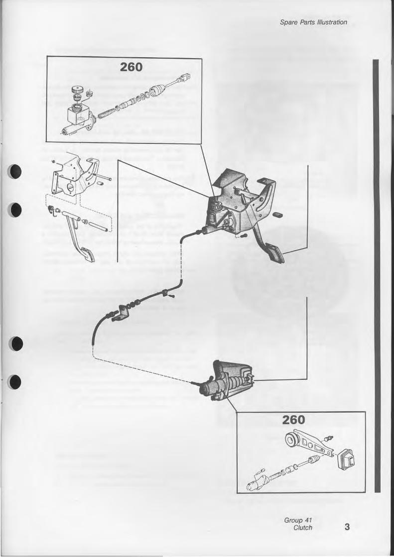
Spare Parts Illustration
260
'(j
260
Group 41 Clutch 3

Clutch operation
4
240 Model Bearlng No. 672122-9 Pressure Plate No. 381249-2
Flg. 1
260 Model Bearlng No. 381213-8 Pressure Plste No. 381207-0
Flg.2
Group 41 Clutch
Replacing clutch assembly
Two different designs of pressure plates and release hearings are currently used in production of Model 240 (DL. GL. GT and Diesel) and Model 260 (GLE and Coupe).
Model 240 (DL, GL, GT and Diesel)
The fingers of the pressure plate are straight and must use the corresponding release bearing, as shown on illustration. The release bearing is 43 mm (1-11/16") in length.
This pressure plate is the only one currenlly stocked by our Spare Parts Division-only the longer release bearing is to be used. See Rg. 1.
Model 260 (GLE and Coupe)
The fingers of the pressure plate are raised approximately 7mm (9/32" ) at the center. Consequently a shorter release bearing is 36.5mm (1·7/ 16" ) in length.
When replacing the clutch pressure plate assembly. care is to be taken to use only the matching shorter bearing. See Fig. 2.
IMPQRTANT: Pressure plates and release bearings must atways be of the correcl combination and should never be interchanged.
• •
•

Replacing clutch operating cable
1. Put front end on stands. Remove under-dash panel.
2. First rem ove return spring. Then disconnect clutch cable at clutch fork. Pull out cable.
3. Remove clevis pin at cable upper end. Pull cable out of rubber grommet in firewall.
4. Push new cable into the rubber grammet in fi rewall. Re-install clevis pin.
5. Fit adjustment device in the bell housing. Connect cable tO clutch fork. Install return spring.
6. Adjust clutch fork free play to approx. 3-5 mm (1/8" ).
Replacing clutch pedal / bushing
The instructions below cover replacement of pedal and / or bushings.
1. Remove clevis pin securing cable to cl utch pedal. Aemove nut, pull out bolt and remove pedal.
2. Remove tubular shaft. Drive out bushings with a suitable drift.
3. Pre-Iubricate new bushings with grease and instaU them. Install tubular shaft.
4. Position pedal and attach bolt. Install and torque nut. Reconnect cable and clevis pin.
Removing clutch
Replace clutch disc {clutchl
1. Remove transmission according to instructions. 2. Remove upper bolt for starter motor.
Clutch operation
3. Remove release bearing. Disconnect cable from release fork.. Slacken cable sheath from bracket.
Release bearing
4. Aemove bolts. Remove flywheel housing. 5. Remove bolt for release fork ball joint. Remove
ball and release fork.. 6. Remove bolts holding clutch to flywheel. loosen
them crosswise a couple of turns at a time to prevent warping. Remove clutch and clutch plate.
Removing clutch
Clutch facing replacement
1. Drill out rivelS with a drill having same diameter as rivets, 3.5 mm (9f64"). Remove old facings.
Group 41 Clutch 5

Clutch shaft
2.
1. Disc 2. Facings 3, Spring
Clutch disc
4. Damping spring 5. Hub
VOLVO ,.~
Check clutch plate. The indentations on the tongues should be even. The clutch plate must not be warped. The clutch springs and rivets in hub should fit securely and not show any signs of laoseness. Check to make sure that there are no cracks. If the clutch plate has any defects. il should be replaced.
3. Rivet new facings (preferably in a rivet press). NQTE: the rivets should be inserted from the side on which the facing lies and riveted from the opposite direction against the disc. Use every other hale in the facing. After riveting, the facings should be spaced from each other as determined by the indentations on the clutch disc. This is most important in order to achieve a smooth engagement when starting and driving. The clutch facings must be absolutely free from oil. Oil on the facings can cause clutch grabbing.
Servicing clutch shaft pilot bearing
1. Use puller hammer to remove pilot bearing.
6
If bearing, af ter cleaning and light oiling, runs smoothly and evenly and has no noticeable play, it should be packed with ball bearing grease and reinstalled. NQTE: heat-resistant grease should be used,
Group 41 Clutch
Pilot bearing removal
Clutch carrier inspection
As the clutch carrier cannot be disassembled, it must be replaced complete. Check the clutch carefully. Check pressure plate for damage by heat, cracks, scoring or other damage ,on the friction surface. Check the curvature of the pressure plate with a steel ruler, which is placed diagonally across the friction surface of the pressure plate. Then measure the distance be
tween the straight edge of the ruler and the inner diameter of the pressure plate. This measurement must not exceed 0.03 mm (0.00012").
'02 08'
Checking curvature of pressure plate
There must be no "crowning", i.e. clearance between the straight edge of the (uler and the outer diameter of the oressure plate. Check at several points. Check the pressure spring carefully. If it is cracked or damaged in anyway, the clutch should be replaced.
Check the release bearing by turning it a few times under light pressure so that the balls ratate against the races. The bearing should turn easily without binding at any point. The release bearing should also slide easily on the guide sleeve from the transmission.
• •

Clutch installation
Before installation. check that clutch facings, flywheel and pressure plate are completely free from oil. Wash them with gasoline and wipe off with a dean piece of cloth.
1. Set up the clutch plate (the longest side of the hub facing backwards) together with dutch.lnsert centering mandrel 2484 as a guide in the pilot bearing in the flywheel.
2. Install six balts which hold the dutch. Tighten them crosswise a couple of tums at a time. Remove centering mandrel.
3. Install release yoke in flywheel housing. 4. Install upper balt for starter motor in the housing
and install the housing. Install balts in the 101-lowing order: First four upper (7 / 16") balts. and then lower balts for the starter motor, and finally two Iower (3 / 8'") balts. The nut for the starter motor upper bolt is installed aher the cable has been attached.
Clutch installation
5. Inser! cable shaft in bracket and rear nut. Secure cable in release fork. Install release bearing.
6. Install and tighten nut for the upper starter motor balt.
7. Install the transmission according to instructions. 8. AdjusI clutch pedal play.
----------- Addilionallnformalion -----------
II is possible lo inslall Ihe rubbar washer on clulch cable incorrectly. Such installation will cause the recessed part of the washer to face Ihe wrong direction. This will preventthe steal washer from being locatad in ils seat and will cause the rubber washer to crack and eventually fall off.
As a result of the incorrect installation, the clutch will develop an abnormal slip during declutching operation. Premature !ailure of the clutch disc may occur.
CORRECT
Sleel Was her
Rubber Washer
INCORRECT
Group 41 Clutch 7

• ~
• I ~ I

• •
• •
Group 45
Propeller Shaft
Index Description
Spare Parts Illustrations
Service Procedures Replacing support bearing .......... . .. . ...•. Propeller shaft . .. . ....... . Re-building U-Joints ............. . ..........•..•..
Description
.~ 2 3 4 5 6 7
Propeller shaft with support beating
,. Flange on transmission 4. Support bearing 2. Front universal joint 5. Intermediate universal joint 3. Front section of propeller 500ft 6. Rear propeller shaft
8
, 2
4 4-5 6
Description
VOLVO 109751
7. Rear universal joint 8. Flange on rear a~le
The propeller shaft is a divided, tubular type shaft, see Fig. above. The front section rear end is formed as a splined sleeve. The corresponding splined shaft carries one of the intermediate universal joint yakes. The front seclian rear end is supported by a ball bearing. The ball bearing is in turn installed in a rubber bearing housing, which is attached to the propeller shaft tunnel with a CQver, see Fig., right. The propener
shaft has three universal joints. Each jOint coinsists of a cross with four trunnians which are carried in
flange yakes by needle bearings. Support bearing A propeller shaft is pairad and balanced as a unit. Front
and rear sections are individuallv marked with a vellow dot and an arrow. The propeller shaft must be replaced
ont y as apaired unit and the front and rear sections
have to be installed so that the arrows (the dots) point
towards each other.
1.
2. 3. 4. 5. 6.
Front section of propeller shaft Floor tunnel Dust coyer 8all bearing Rubber housing Dust cover
7. No< 8. Rear section of propeller
shaft 9. Rubber cover
'0. Washer 11. Suspension spring 12. Cover
Group 45 Propeller shaft 1
Spare Parts Illustration
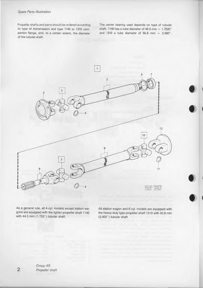
Propeller shafts and parts should be ordered according to type of transmission and type 1140 or 1310 companion flange, and, to a certsin extent, the diameter of the tubular shaft.
As a general rule, all 4-cyl. models except station wagons are equipped with the lighter propeller shaft 1140 with 44.5 mm (1.753" ) tubular shaft.
2 Group 45 Propeller shaft
The center bearing used depends on type of tubular shaft. 1140 has a tube diameter of 44.5 mm = 1.7520" and 1310 a tube diameter of SO.8 mm = 2.000".
5
6 7
12
11
VOL\() PARTS 1 Ol.O 12741
All station wagon and 6 cyl. models are equipped with the heavy-dUly typa propeller shaft 1310 with SO.8 mm (2.002" ) tubular shatt.
I
II

• •
• •
Spare Parts lfIustration
1140 1310 A- J6,7 A-413 S .. 45,4 Basi,l
VOLVO PARTS 1 040 12740
Group 45 Propeller shaft 3

Remova!, disassembly
Service Procedures
Re placing s upport bea ring
1. Jack up the vehicle and put it on stands. Slacken the propeller shaft from the rear axle flange. Bend back the lock washer and remove the nut at the sliding joint. Pull out the propeller shaft to the rear.
2. Loosen the support bearing cover. Pull off the complete support bearing.
3. Press the old bearing out of the rubber housing. Install the new bearing.
4. Install support bearing and other parts in reverse order to remove. If the splined joint appears dry, lubricate il with grease mixed with molybdenum disu[phide (Molykote.) Make sure that the arrows point toward each other on propeller shahs paired and balanced together.
Propeller Sh af t
Removal
Jack up the vehicle. Slacken the propeller shaft from the transmission and rear axle flanges. For 245 use impact air wrench and special socket 2846 to loosen the bolts. Loosen the support bearing cover and take down the complete propeller shatt. For 242 and 244 use tool 2779 for the front flange bolts and tool 2846 for the rear flange bolts, see Fig. below:
4
Removing bolts
Group 45 Propeller shaft
Disassembly
Propeller shaft disassembly
,. 8end back the lock washer and remove the nut for the support bearing. Aemove the propeller shaft rear section. Pull off the support bearing.
2. Take the support bearing out of the housing.
Disassembling universal joints
,. Aemove the snap rings which secure the needle bearings in the yokes, see Fig. below:
Removing snap ring
VOLVO 101771
2. Secure the shaft in a vise so that the universal joint comes as near as possible to the vise jaws. Remember that the propeller shaft is tubular and can easily be deformed.
3. Use a hammer and metal punch to drive the spider as far as il will go in one direction. The needle bearing will then come about half way out.
•

• •
• •
4. Then drive the spi der as far as il will go in the opposite direction, see Fig. below:
Removing spider. first step
5. Drive out one of the need[e bearings with a lhin metal punch. Remove the spider, see Fig. below: Drive out the other needle bearing.
Inspection
VOLVO Im 179
II is extremely importsnl thai the propeller shatt is straight. The inspeclion must be careful since even minor damage on the propeller shatt can cause vibration. The shatt should be sel up bet.veen centers and checked along its entire lengtn with an indicator gauge while il is rOIating. If it is out-ol-lrue mora Ihan 0.25 mm (0.010") the shatt must be replaced. NOTE: No attempt should be made to straighten a damaged propeller shatt: replace it. Examine the support bearing. Press the bearing races against each other by hand and turn them in opposite directions. The bearing should run easily without binding at any point. If it binds, scrap the bearing and replace il.
Inspection, assembly
Assembly
Assembling universal joints
,. If old needle bearings are installed, check Ihat they are filled with grease and that the rubber seals are not damaged. New hearings should be halffilled with grease.
2. Insert the spider in the flange yoke. Push the spider in one direction so that the needle bearing can be installed in the trunnion, see Fig. below:
Then press in the needle bearing far enough that the snap ring can be inSlallOO. Use a drift with a diameter slightly less than that of the needle bearing sleeve.
3. Install the other needle bearing and repeat the procedure.
4. Do the same on the remaining yoke.
Installation
Installation is in reverse order to remova!.
Group 45 Propeller shah 5

U-joints
6 Group 45 Propeller shaft
Re-building U-joints
VOLVO , .. 2«'''
Instructions for press tool 999 5018 and puller 999 5019
A. Jaws B. Arbor C. Rod D. SuppOrt. Part of 999 501 B
Disassembling universal joint
Remove the lock rings and position the U-joint in the press tool. Use the pedal to move the spider. If the power is not sufficient, use a hammer on the rod.
Move the U-joint to the puller. Align the needle bearing between the jaws. Press down the handle which w ill remove the needle bearing.
Assembling universal joint
locate the spi der with seals in one of the coupling flanges. locate one needle bearing. Position the U-joint in the press tool and press in the needle bearing unt;1 the lock ring can be installed. Turn the U-joiot over and press in the other needle bearing. Install spider and needle bearings in the same way in the other coupling flange. Install the lock rings.

• •
• '.
•
U-joints
Replacing press tool arbor
Loosen the screw and remove the arbor. Position the other 8roor and tighten the screw. NOTE: The large arbor has two recesses to be positioned vertically., For this reasan il is provided with a hole corresponding with the screw.
Replacing pulter jaws
Remeve the O-ring and use a punch to press out the pins. Jaw$ for small U-joints Jaws for large U-joints
Lift the ring and bend the jaws aside.
9999026 9999027
Hold the lever in the upper position and press the jaws into position. Position the ring with the side marked " up" upwards. Install the pins. Bend the spring, which retains the lower ands of the jaws, into position. Install
the O-ring.
Group 45 Propeller shaft 7

• •
• '.
VOLVO SUPPORTS VOlUNTARY MECHANIC CERTIFICATION
BY THE N.I.A.S.E.
(U.S.A.Only)
