section k materials and workmanship g.r. mckay*4)0400.pdf · section k materials and workmanship...
TRANSCRIPT
4 0 0
Section K
MATERIALS AND WORKMANSHIP
G.R. McKay*
This paper is the result of deliberations of the Society's Study Group for the Seismic Design of STEEL STRUCTURES.
1. CONTENTS
2. INTRODUCTION 3. LAMELLAR TEARING 4. LOW CYCLE FATIGUE 5. REQUIREMENTS OF EXISTING CODES 6. MATERIALS 7. FABRICATION AND WORKMANSHIP 8. QUALITY CONTROL 9. CONCLUSIONS
10. REFERENCES
2. INTRODUCTION
Low carbon steel normally used in structural work usually have a high ductility in the direction of rolling. Provided the design is as per the accompanying Study Group papers and that these design assumptions are satisfied in the actual structure, the steel can withstand a number of cycles of yielding in either direction whilst maintaining a substantially constant load capacity. However, brittle failure at welded joints due to lamellar tearing, brittle fracture or low cycle fatigue must be guarded against by proper detailing, good workmanship and selection of clean notch ductile steel.
Structures designed assuming other than an elastic response should be specially inspected to ensure a higher than normal quality assurance in all locations likely to undergo plastic deformation in the event of an earthquake.
3. LAMELLAR TEARING
While lamellar tearing is not peculiar to earthquake resistant structures it is caused by the restraint of welded joints of components which are thick and relatively short or stiff. Such joints are common in steel earthquake resisting frames. It generally occurs when butt or fillet welds with a size of 20 mm or greater are made on the surface of plates or sections (particularly over approximately 30 mm thick), under conditions of high restraint. For applications well below these limits, the risk of lamellar tearing is virtually negligible.
Lamellar tearing is tearing (i.e. fracture, cracking or separation) of parent
Senior Design Engineer, Ministry of Works and Development, Wellington
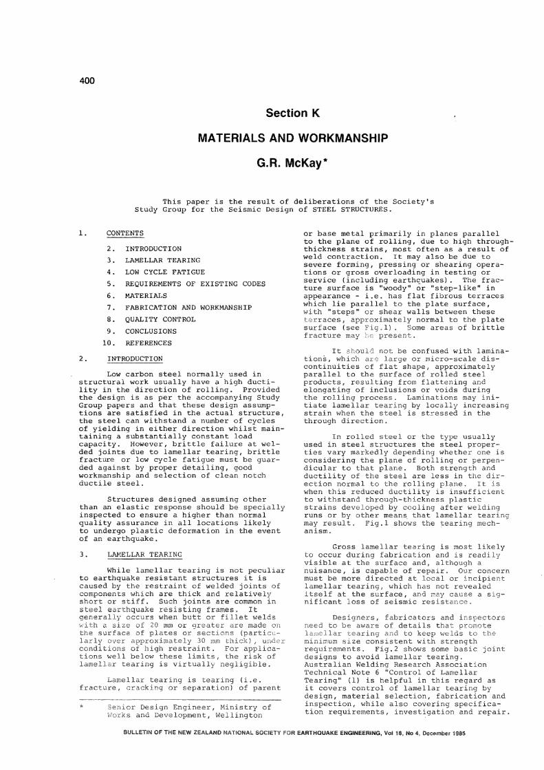
or base metal primarily in planes parallel to the plane of rolling, due to high through-thickness strains, most often as a result of weld contraction. It may also be due to severe forming, pressing or shearing operations or gross overloading in testing or service (including earthquakes). The fracture surface is "woody" or "step-like" in appearance - i.e. has flat fibrous terraces which lie parallel to the plate surface, with "steps" or shear walls between these terraces, approximately normal to the plate surface (see Fig.1) . Some areas of brittle fracture may be present.
It should not be confused with laminations , which are large or micro-scale discontinuities of flat shape, approximately parallel to the surface of rolled steel products, resulting from flattening and elongating of inclusions or voids during the rolling process. Laminations may initiate lamellar tearing by locally increasing strain when the steel is stressed in the through direction.
In rolled steel or the type usually used in steel structures the steel properties vary markedly depending whether one is considering the plane of rolling or perpendicular to that plane. Both strength and ductility of the steel are less in the direction normal to the rolling plane. It is when this reduced ductility is insufficient to withstand through-thickness plastic strains developed by cooling after welding runs or by other means that lamellar tearing may result. Fig.1 shows the tearing mechanism.
Gross lamellar tearing is most likely to occur during fabrication and is readily visible at the surface and, although a nuisance, is capable of repair. Our concern must be more directed at local or incipient lamellar tearing, which has not revealed itself at the surface, and may cause a significant loss of seismic resistance.
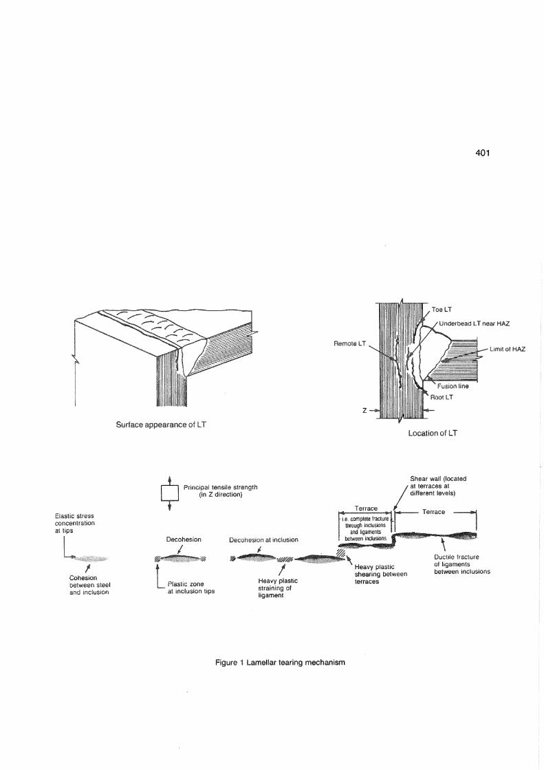
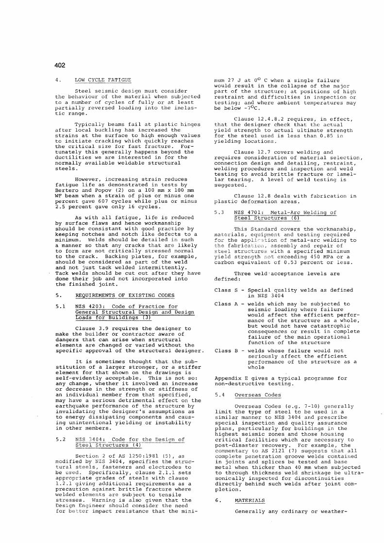
Designers, fabricators and inspectors need to be aware of detaiIs that promote lamellar tearing and to keep welds to the minimum size consistent with strength requirements. Fig.2 shows some basic joint designs to avoid lamellar tearing. Australian Welding Research Association Technical Note 6 "Control of Lamellar Tearing" (1) is helpful in this regard as it covers control of lamellar tearing by design, material selection, fabrication and inspection, while also covering specification requirements, investigation and repair.
BULLETIN OF THE NEW ZEALAND NATIONAL SOCIETY FOR EARTHQUAKE ENGINEERING, Vol 18, No 4, December 1985
4 0 1
Surface appearance of L T
Remote LT
Z -
Toe LT
Under bead LT near HAZ
Limit of HAZ
Location of LT
Elastic stress concentration at tips
Cohesion between steel and inclusion
Principal tensile strength (in Z direction)
Decohesion
^ Plastic zone at inclusion tips
Decohesion at inclusion
Heavy plastic straining of ligament
Terrace
i.e. complete fracture through inclusions
and ligaments between inclusions
Shear wall (located ' at terraces at different levels)
Terrace
Heavy plastic shearing between terraces
Ductile fracture of ligaments between inclusions
Figure 1 Lamellar tearing mechanism
402
4 . LOW CYCLE FATIGUE
Steel seismic design must consider the behaviour of the material when subjected to a number of cycles cf fully or at least partially reversed loading into the inelastic range.
Typically beams fail at plastic hinges after local buckling has increased the strains at the surface to high enough values to initiate cracking which quickly reaches the critical size for fast fracture. Fortunately this generally happens beyond the ductilities we are interested in for the normally available weldable structural steels.
However, increasing strain reduces fatigue life as demonstrated in tests by Bertero and Popov (2) on a 100 mm x 100 mm WF beam when a strain of plus or minus one percent gave 607 cycles while plus or minus 2.5 percent gave only 16 cycles.
As with all fatigue, life is reduced by surface flaws and hence workmanship should be consistant with good practice by keeping notches and notch like defects to a minimum. Welds should be detailed in such a manner so that any cracks that are likely to form are not critically stressed normal to the crack. Backing plates, for example, should be considered as part of the weld and not just tack welded intermittently. Tack welds should be cut out after they have done their job and not incorporated into the finished joint.
5. REQUIREMENTS OF EXISTING CODES
5.1 NZS 4203: Code of Practice for General Structural Design and Design Loads for Buildings (3)
Clause 3.9 requires the designer to make the builder or contractor aware of dangers that can arise when structural elements are changed or varied without the specific approval of the structural designer.
It is sometimes thought that the substitution of a larger stronger, or a stiffer element for that shown on the drawings is self-evidently acceptable. This is not so: any change, whether it involved an increase or decrease in the strength or stiffness of an individual member from that specified, may have a serious detrimental effect on the earthquake performance of the structure by invalidating the designer's assumptions as to energy dissipating components and causing unintentional yielding or instability in other members.
5 .2 NZS 3404 ; Code for the Design of Steel Structures (4)
Section 2 of AS 1250 :1981 (5) , as modified by NZS 3404 , specifies the structural steels, fasteners and electrodes to be used. Specifically, clause 2.1.1 sets appropriate grades of steels with clause 1.2.1 giving additional requirements as a precaution against brittle fracture where welded elements are subject to tensile stresses. Warning is also given that the Design Engineer should consider the need for better impact resistance that the mini
mum 27 J at 0° C when a single failure would result in the collapse of the major part of the structure; at positions of high restraint and difficulties in inspection or testing; and where ambient temperatures may be below -7°C.
Clause 12.4 . 8 . 2 requires, in effect, that the designer check that the actual yield strength to actual ultimate strength for the steel used is less than 0.85 in yielding locations.
Clause 12.7 covers welding and requires consideration of material selection, connection design and detailing, restraint, welding procedures and inspection and weld testing to avoid brittle fracture or lamellar tearing. A level of weld testing is suggested.
Clause 12.8 deals with fabrication in plastic deformation areas.
5.3 NZS 4701: Metal-Arc Welding of Steel Structures (6)
This Standard covers the workmanship, materials, equipment and testing required for the application of metal-arc welding to the fabrication, assembly and repair of steel structures with a specified minimum yield strength not exceeding 450 MPa or a carbon equivalent of 0.53 percent or less.
Three weld•acceptance levels are defined:
Class S - Special quality welds as defined in NZS 3404
Class A - welds which may be subjected to seismic loading where failure would affect the efficient performance of the structure as a whole, but would not have catastrophic consequences or result in complete failure of the main operational function of the structure
Class B - welds whose failure would not seriously affect the efficient performance of the structure as a whole
Appendix E gives a typical programme for non-destructive testing.
5.4 Overseas Codes
Overseas Codes (e.g. 7-10) generally limit the type of steel to be used in a similar manner to NZS 3404 and prescribe special inspection and quality assurance plans, particularly for buildings in the highest seismic zones and those housing critical facilities which are necessary to post-disaster recovery. For example, the commentary to AS 2121 (7) suggests that all complete penetration groove welds contained in joints and splices be tested and base metal when thicker than 40 mm when subjected to through thickness weld shrinkage be ultra-sonically inspected for discontinuities directly behind such welds after joint completion .
6. MATERIALS
Generally any ordinary or weather-
Welds with no through-thickness stressing.
Welds with reduced through-thickness stressing.
Welded joint to avoid defects
Figure 2 Basic joint design to avoid Lamellar tearing.
404
resistant weldable structural steel may be used. However in the selection of the steel the ductility requirements appropriate to the design method must be considered.
Elastically responding structures have no special requirements over and above normal good practice.
Structures designed to have a ductile or limited ductile response should comply with the above code requirements and have a maximum specified Fy not greater than 360 MPa and an ultimate strength to yield stress ratio of at least 1.4.
Cold rolled RHS is not suitable for other than elastically responding structures unless annealed to restore the original steel resistance to low cycle fatigue and improve the yield to ultimate stress ratio.
Most testing of earthquake performance reported in the literature has been on steel to ASTM A36 or A441 (11) .
While it is not possible to judge the resistance of steel to lamellar tearing by ladle or heat analysis, there is evidence that steels with a sulphur content of about 0.03 percent or more have a higher incidence of lamellar tearing than those with a low sulphur content of 0.02 percent or less. If possible low sulphur clean steels should be selected for critical joints.
Special steels with enhanced through section properties usually contain rare earths, such as cerium or calcium to either reduce sulphur content or to ensure inclusions remain small and spherical during rolling. Due to the premium they attract such steels could only be recommended for critical joints. They are no guarantee against lamellar tearing, nor a panacea for bad detailing or fabrication practices.
If stress governs choice of a particular member size - consider using a steel with a higher yield point but check availability \
1. FABRICATION AND WORKMANSHIP
With frames, both braced and moment resisting, being designed with sufficient overstrength built into selected elements to satisfy capacity design requirements (except for elastically responding structures) , workmanship should be such that this design assumption is satisfied in the actual structure. Thus fabrication methods are required to minimise notch-like defects and brittleness in areas likely to undergo plastic tension deformation (Clause 12.8 of NZS 3404 refers) .
The jointing methods, welding and bolting, used in connecting steel members are of prime importance because they are very dependent on procedures and operator skill.
At the risk of playing down the importance of fabrication methods and sequences to minimise notch-like defects and restraint it is perhaps worth mentioning that punching is not favoured where plastic strains or fatigue loading may be a possibility (not
only in potential beam hinges). Owens et al. (12) after a series of tests concluded that punched holes should not be permitted in plastically designed structures where deformation capacity may be required of net sections in tension or in structures that operate at low temperatures or are subject to fatigue loading.
Polmear et al. (13) studied fatigue characteristics of a simple tensile splice with respect to the method of hole preparation and concluded that specimens with holes reamed to remove the hardened material immediately around the hole performed no better than punched holes for high strength friction grip bolts tightened to the turn-of-the-nut method. The fatigue life of both being substantially less than for splices with drilled holes.
8. QUALITY CONTROL
Special inspection during fabrication and erection to ensure a higher than normal quality assurance should be provided in all locations likely to undergo plastic deformation in the event of an earthquake (NZS 3404 and NZS 4701 refer). This is required as design stresses are not limited to values related to the nominal yield stress of the material, but reach the actual yield stress, with some strain hardening, of the material during several cycles of the earthquake.
Not only is ductility and low cycle fatigue resistance required in these regions but the design forces on joints and connecting elements are governed by the actual strength of these regions.
Frames and bracing designed to elastic design procedures need not be subject to the above special inspection. However good practice may require a high level of quality assurance for other than earthquake reasons.
The special inspection together with testing should be in the form of a Quality Assurance Plan specified for the designated seismic system. Such a plan would include: (a) Confirmation of material properties
including actual yield and ultimate strengths, ductility and carbon equivalent.
(b) Check on the through section properties if lamellar tearing could be a problem.
(c) Continuous special inspection during all shop and field welding of all multiple-pass welded connections.
(d) Periodic special inspection during high-strength bolting operations.
(e) Testing of welds to appropriate class as per NZS 4701.
(f) Ultrasonic testing for discontinuities behind and adjacent to welds after joint completion when through thickness weld shrinkage strains could lead to lamellar tearing.
(g) Periodic testing of high-strength bolts. (h) All parties with a direct interest in
the construction (i.e. owner, designer and contractor) be regularly furnished with reports and all deficiencies be
4 0 5
notified for immediate correction.
9. CONCLUSIONS
In the selection of steel for earthquake resistance the ductility requirements appropriate to the design method must be considered.
A combination of good practice for design, detailing and fabrication procedures is required to avoid brittle fracture, lamellar tearing and low cycle fatigue.
Higher than normal quality assurance is required of all locations in the structure that may be subjected to plastic deformation in the event of an earthquake.
10. REFERENCES
(1) Australian Welding Research Association , Technical Note 6, "Control of Lamellar Tearing", April 1976.
(2) Bertero, Vitelmo V. and Popov, Egor P., "Effect of Large Alternating Strains on Steel Beams, "Journal of the Structural Division ASCE, February 1965, Vol. 91, No. ST1, pp. 1-12.
(3) New Zealand Standard 4203, "Code of Practice for General Structural Design and Design Loadings for Buildings", Standards Assoc. of N.Z., 1984.
(4) New Zealand Standard 3404, "Code for the Design of Steel Structures", Standards Assoc. of N.Z., 1977.
(5) Australian Standard 1250, "SAA Steel Structures Code", Standards Assoc. of Austr., 1981.
(6) New Zealand Standard 4701, "Metal-Arc Welding of Steel Structures", Standards Assoc. of N.Z., 1981.
(7) Australian Standard 2121, "SAA Earthquake Code", Standards Assoc. of Austr., 1979.
(8) Applied Technology Council, California, ATC-3-06, "Tentative Provisions for the Development of Seismic Regulations for Buildings", 1978.
(9) Seismology Committee, Structural Engineers Association of California, "Recommended Lateral Force Requirements and Commentary", 1980.
(10) International Conference of Building Officials, "Uniform Building Code", 1982 edition.
(11) ASTM A36-81a, "Specification for Structural Steel", and A441-81, "Specification for High-Strength Low Alloy Structural Mangarese Varadium Steel", Amer. Soc. for Testing and Materials, Philadelphia, 1981.
(12) Owens, G.W., Driver, P.J. and Krige, G.J., "Punched Holes in Structural Steelwork", Journal of Constructional Steel Research, May 1981.
(13) Polmear , I.J., Tuisk , U.U., Stephens , P.J. and Voreng, P.R.B., "Fatigue Characteristics of a Simple Bolted Joint", The Institution of Engineers, Australia, Civil Engineering Transactions, October 1971.