section materials of engineering - analysischamp.comanalysischamp.com/markshandbookmecheng03.pdf ·...
TRANSCRIPT

Section 6Materials of Engineering
BY
EUGENE A. AVALLONE Consulting Engineer; Professor of Mechanical Engineering, Emeritus,The City College of The City University of New York
HAROLD W. PAXTON United States Steel Professor Emeritus, Carnegie Mellon UniversityJAMES D. REDMOND Principal, Technical Marketing Resources, Inc.MALCOLM BLAIR Technical and Research Director, Steel Founders Society of AmericaROBERT E. EPPICH Vice President, Technology, American Foundry SocietyL. D. KUNSMAN Late Fellow Engineer, Research Labs, Westinghouse Electric Corp.C. L. CARLSON Late Fellow Engineer, Research Labs, Westinghouse Electric Corp.J. RANDOLPH KISSEL President, The TGB PartnershipLARRY F.WIESERMAN Senior Technical Supervisor, ALCOARICHARD L. BRAZILL Technology Specialist, ALCOAFRANK E. GOODWIN Executive Vice President, ILZRO, Inc.DON GRAHAM Manager, Turning Products, Carboloy, Inc.ARTHUR COHEN Formerly Manager, Standards and Safety Engineering, Copper DevelopmentAssn.
JOHN H. TUNDERMANN Formerly Vice President, Research and Technology, INCOInternational, Inc.
JAMES D. SHEAROUSE, III Late Senior Development Engineer, The Dow Chemical Co.PETER K. JOHNSON Director, Marketing and Public Relations, Metal Powder IndustriesFederation
JOHN R. SCHLEY Manager, Technical Marketing, RMI Titanium Co.ROBERT D. BARTHOLOMEW Associate, Sheppard T. Powell Associates, LLCDAVID A. SHIFLER MERA Metallurgical ServicesDAVID W. GREEN Supervisory Research General Engineer, Forest Products Lab, USDAROLAND HERNANDEZ Research Engineer, Forest Products Lab, USDAJOSEPH F. MURPHY Research General Engineer, Forest Products Lab, USDAROBERT J. ROSS Supervisory Research General Engineer, Forest Products Lab, USDAWILLIAM T. SIMPSON Research Forest Products Technologist, Forest Products Lab, USDAANTON TENWOLDE Supervisory Research Physicist, Forest Products Lab, USDAROBERT H.WHITE Supervisory Wood Scientist, Forest Products Lab, USDASTAN LEBOW Research Forest Products Technologist, Forest Products Lab, USDAALI M. SADEGH Professor of Mechanical Engineering, The City College of The City University ofNew York
WILLIAM L. GAMBLE Professor Emeritus of Civil and Environmental Engineering, University ofIllinois at Urbana-Champaign
ARNOLD S. VERNICK Formerly Associate, Geraghty & Miller, Inc.GLENN E. ASAUSKAS Lubrication Engineer, Chevron Corp.STEPHEN R. SWANSON Professor of Mechanical Engineering, University of Utah
6-1
6.1 GENERAL PROPERTIES OF MATERIALSRevised by E. A. Avallone
Chemistry . . . . . . . . . . . . . . . . . . . . . . . . . . . . . . . . . . . . . . . . . . . . . . . . . . . 6-3Specific Gravities and Densities and Other Physical Data . . . . . . . . . . . . . . . 6-7
6.2 IRON AND STEELby Harold W. Paxton
Classification of Iron and Steel . . . . . . . . . . . . . . . . . . . . . . . . . . . . . . . . . . 6-12Steel . . . . . . . . . . . . . . . . . . . . . . . . . . . . . . . . . . . . . . . . . . . . . . . . . . . . . . 6-13Effect of Alloying Elements on the Properties of Steel. . . . . . . . . . . . . . . . . 6-18
Principles of Heat Treatment of Iron and Steel. . . . . . . . . . . . . . . . . . . . . . . 6-19Composite Materials . . . . . . . . . . . . . . . . . . . . . . . . . . . . . . . . . . . . . . . . . . 6-20Thermomechanical Treatment . . . . . . . . . . . . . . . . . . . . . . . . . . . . . . . . . . . 6-21Commercial Steels. . . . . . . . . . . . . . . . . . . . . . . . . . . . . . . . . . . . . . . . . . . . 6-21Tool Steels. . . . . . . . . . . . . . . . . . . . . . . . . . . . . . . . . . . . . . . . . . . . . . . . . . 6-28Spring Steel. . . . . . . . . . . . . . . . . . . . . . . . . . . . . . . . . . . . . . . . . . . . . . . . . 6-29Special Alloy Steels. . . . . . . . . . . . . . . . . . . . . . . . . . . . . . . . . . . . . . . . . . . 6-29Stainless Steels (BY JAMES D. REDMOND) . . . . . . . . . . . . . . . . . . . . . . . . . . . 6-29

6.3 IRON AND STEEL CASTINGSby Malcolm Blair and Robert E. Eppich
Classification of Castings . . . . . . . . . . . . . . . . . . . . . . . . . . . . . . . . . . . . . . 6-34Cast Iron . . . . . . . . . . . . . . . . . . . . . . . . . . . . . . . . . . . . . . . . . . . . . . . . . . . 6-35Steel Castings . . . . . . . . . . . . . . . . . . . . . . . . . . . . . . . . . . . . . . . . . . . . . . . 6-40
6.4 NONFERROUS METALS AND ALLOYS;METALLIC SPECIALITIES
Introduction (BY L. D. KUNSMAN AND C. L. CARLSON, Amended by Staff) . . . . . . . . . . . . . . . . . . . . . . . . . . . . . . . . . . . . . . . . . . . . . . . . . 6-46
Aluminum and Its Alloys (BY J. RANDOLPH KISSELL, LARRY F. WIESERMAN,AND RICHARD L. BRAZILL) . . . . . . . . . . . . . . . . . . . . . . . . . . . . . . . . . . . . 6-49
Bearing Metals (BY FRANK E. GOODWIN) . . . . . . . . . . . . . . . . . . . . . . . . . . . 6-58Cemented Carbides (BY DON GRAHAM) . . . . . . . . . . . . . . . . . . . . . . . . . . . . 6-58Copper and Copper Alloys (BY ARTHUR COHEN) . . . . . . . . . . . . . . . . . . . . . 6-62Jewelry Metals (Staff Contribution) . . . . . . . . . . . . . . . . . . . . . . . . . . . . . . . 6-71Low-Melting-Point Metals and Alloys (BY FRANK E. GOODWIN) . . . . . . . . . 6-72Metals and Alloys for Use at Elevated Temperatures(BY JOHN H. TUNDERMANN) . . . . . . . . . . . . . . . . . . . . . . . . . . . . . . . . . . . 6-73
Metals and Alloys for Nuclear Energy Applications (BY L. D. KUNSMANAND C. L. CARLSON; Amended by staff) . . . . . . . . . . . . . . . . . . . . . . . . . 6-79
Magnesium and Magnesium Alloys (BY JAMES D. SHEAROUSE, III) . . . . . . . 6-82Powdered Metals (BY PETER K. JOHNSON) . . . . . . . . . . . . . . . . . . . . . . . . . . 6-83Nickel and Nickel Alloys (BY JOHN H. TUNDERMANN) . . . . . . . . . . . . . . . . . 6-86Titanium and Zirconium (BY JOHN R. SCHLEY). . . . . . . . . . . . . . . . . . . . . . . 6-88Zinc and Zinc Alloys (BY FRANK E. GOODWIN) . . . . . . . . . . . . . . . . . . . . . . 6-90
6.5 CORROSIONby Robert D. Bartholomew and David A. Shifler
Introduction. . . . . . . . . . . . . . . . . . . . . . . . . . . . . . . . . . . . . . . . . . . . . . . . . 6-92Thermodynamics of Corrosion . . . . . . . . . . . . . . . . . . . . . . . . . . . . . . . . . . 6-93Corrosion Kinetics. . . . . . . . . . . . . . . . . . . . . . . . . . . . . . . . . . . . . . . . . . . . 6-94Factors Influencing Corrosion . . . . . . . . . . . . . . . . . . . . . . . . . . . . . . . . . . . 6-95Forms of Corrosion . . . . . . . . . . . . . . . . . . . . . . . . . . . . . . . . . . . . . . . . . . . 6-97Corrosion Testing . . . . . . . . . . . . . . . . . . . . . . . . . . . . . . . . . . . . . . . . . . . 6-102Corrosion Protection Methods . . . . . . . . . . . . . . . . . . . . . . . . . . . . . . . . . . 6-103Corrosion in Industrial and Power Plant Steam-Generating Systems . . . . . 6-105Corrosion in Heating and Cooling Water Systems and Cooling Towers . . . 6-109Corrosion in the Chemical Process Industry. . . . . . . . . . . . . . . . . . . . . . . . 6-110
6.6 PAINTS AND PROTECTIVE COATINGSRevised by Staff
Paint Ingredients . . . . . . . . . . . . . . . . . . . . . . . . . . . . . . . . . . . . . . . . . . . . 6-111Paints . . . . . . . . . . . . . . . . . . . . . . . . . . . . . . . . . . . . . . . . . . . . . . . . . . . . 6-111Other Protective and Decorative Coatings . . . . . . . . . . . . . . . . . . . . . . . . . 6-113Varnish . . . . . . . . . . . . . . . . . . . . . . . . . . . . . . . . . . . . . . . . . . . . . . . . . . . 6-114Lacquer . . . . . . . . . . . . . . . . . . . . . . . . . . . . . . . . . . . . . . . . . . . . . . . . . . . 6-115
6.7 WOODby Staff, Forest Products Laboratory, USDA Forest Service.
Prepared under the direction of David W. Green
Composition, Structure, and Nomenclature (BY DAVIDW. GREEN) . . . . . . . 6-115Physical and Mechanical Properties of Clear Wood (BY DAVIDW. GREEN,ROBERTWHITE, ANTON TENWOLDE, WILLIAM SIMPSON, JOSEPHMURPHY, AND ROBERT ROSS) . . . . . . . . . . . . . . . . . . . . . . . . . . . . . . . . . 6-116
Properties of Lumber Products (BY ROLAND HERNANDEZAND DAVIDW. GREEN) . . . . . . . . . . . . . . . . . . . . . . . . . . . . . . . . . . . . . . 6-121
Properties of Structural Panel Products (BY ROLAND HERNANDEZ) . . . . . . . 6-127Durability of Wood in Construction (BY STAN LEBOW AND ROBERTWHITE) . . . . . . . . . . . . . . . . . . . . . . . . . . . . . . . . . . . . . . . . . . . . . . . . . 6-129
Commercial Lumber Standards . . . . . . . . . . . . . . . . . . . . . . . . . . . . . . . . . 6-131
6.8 NONMETALLIC MATERIALSby Ali M. Sadegh
Abrasives. . . . . . . . . . . . . . . . . . . . . . . . . . . . . . . . . . . . . . . . . . . . . . . . . . 6-131Adhesives . . . . . . . . . . . . . . . . . . . . . . . . . . . . . . . . . . . . . . . . . . . . . . . . . 6-133
Brick, Block, and Tile . . . . . . . . . . . . . . . . . . . . . . . . . . . . . . . . . . . . . . . . 6-134Ceramics . . . . . . . . . . . . . . . . . . . . . . . . . . . . . . . . . . . . . . . . . . . . . . . . . . 6-139Cleansing Materials . . . . . . . . . . . . . . . . . . . . . . . . . . . . . . . . . . . . . . . . . . 6-140Cordage. . . . . . . . . . . . . . . . . . . . . . . . . . . . . . . . . . . . . . . . . . . . . . . . . . . 6-141Electrical Insulating Materials . . . . . . . . . . . . . . . . . . . . . . . . . . . . . . . . . . 6-141Fibers and Fabrics . . . . . . . . . . . . . . . . . . . . . . . . . . . . . . . . . . . . . . . . . . . 6-143Freezing Preventives . . . . . . . . . . . . . . . . . . . . . . . . . . . . . . . . . . . . . . . . . 6-144Glass . . . . . . . . . . . . . . . . . . . . . . . . . . . . . . . . . . . . . . . . . . . . . . . . . . . . . 6-145Natural Stones . . . . . . . . . . . . . . . . . . . . . . . . . . . . . . . . . . . . . . . . . . . . . . 6-146Paper . . . . . . . . . . . . . . . . . . . . . . . . . . . . . . . . . . . . . . . . . . . . . . . . . . . . . 6-147Roofing Materials . . . . . . . . . . . . . . . . . . . . . . . . . . . . . . . . . . . . . . . . . . . 6-148Rubber and Rubberlike Materials (Elastomers) . . . . . . . . . . . . . . . . . . . . . 6-150Solvents. . . . . . . . . . . . . . . . . . . . . . . . . . . . . . . . . . . . . . . . . . . . . . . . . . . 6-151Thermal Insulation. . . . . . . . . . . . . . . . . . . . . . . . . . . . . . . . . . . . . . . . . . . 6-153Silicones . . . . . . . . . . . . . . . . . . . . . . . . . . . . . . . . . . . . . . . . . . . . . . . . . . 6-154Refractories . . . . . . . . . . . . . . . . . . . . . . . . . . . . . . . . . . . . . . . . . . . . . . . . 6-154Sealants . . . . . . . . . . . . . . . . . . . . . . . . . . . . . . . . . . . . . . . . . . . . . . . . . . . 6-158
6.9 CEMENT, MORTAR, AND CONCRETEby William L. Gamble
Cement . . . . . . . . . . . . . . . . . . . . . . . . . . . . . . . . . . . . . . . . . . . . . . . . . . . 6-162Lime . . . . . . . . . . . . . . . . . . . . . . . . . . . . . . . . . . . . . . . . . . . . . . . . . . . . . 6-163Aggregates . . . . . . . . . . . . . . . . . . . . . . . . . . . . . . . . . . . . . . . . . . . . . . . . 6-163Water. . . . . . . . . . . . . . . . . . . . . . . . . . . . . . . . . . . . . . . . . . . . . . . . . . . . . 6-164Admixtures . . . . . . . . . . . . . . . . . . . . . . . . . . . . . . . . . . . . . . . . . . . . . . . . 6-164Mortars . . . . . . . . . . . . . . . . . . . . . . . . . . . . . . . . . . . . . . . . . . . . . . . . . . . 6-165Concrete . . . . . . . . . . . . . . . . . . . . . . . . . . . . . . . . . . . . . . . . . . . . . . . . . . 6-166
6.10 WATERby Arnold S. Vernick and Amended by Staff
Water Resources . . . . . . . . . . . . . . . . . . . . . . . . . . . . . . . . . . . . . . . . . . . . 6-171Measurements and Definitions. . . . . . . . . . . . . . . . . . . . . . . . . . . . . . . . . . 6-172Industrial Water . . . . . . . . . . . . . . . . . . . . . . . . . . . . . . . . . . . . . . . . . . . . . 6-174Water Pollution Control . . . . . . . . . . . . . . . . . . . . . . . . . . . . . . . . . . . . . . . 6-175Water Desalination . . . . . . . . . . . . . . . . . . . . . . . . . . . . . . . . . . . . . . . . . . 6-176
6.11 LUBRICANTS AND LUBRICATIONby Glenn E. Asauskas
Lubricants . . . . . . . . . . . . . . . . . . . . . . . . . . . . . . . . . . . . . . . . . . . . . . . . . 6-180Liquid Lubricants . . . . . . . . . . . . . . . . . . . . . . . . . . . . . . . . . . . . . . . . . . . 6-180Lubrication Regimes . . . . . . . . . . . . . . . . . . . . . . . . . . . . . . . . . . . . . . . . . 6-181Lubricant Testing. . . . . . . . . . . . . . . . . . . . . . . . . . . . . . . . . . . . . . . . . . . . 6-181Viscosity Tests. . . . . . . . . . . . . . . . . . . . . . . . . . . . . . . . . . . . . . . . . . . . . . 6-181Other Physical and Chemical Tests . . . . . . . . . . . . . . . . . . . . . . . . . . . . . . 6-182Greases . . . . . . . . . . . . . . . . . . . . . . . . . . . . . . . . . . . . . . . . . . . . . . . . . . . 6-183Solid Lubricants . . . . . . . . . . . . . . . . . . . . . . . . . . . . . . . . . . . . . . . . . . . . 6-184Lubrication Systems . . . . . . . . . . . . . . . . . . . . . . . . . . . . . . . . . . . . . . . . . 6-185Lubrication of Specific Equipment . . . . . . . . . . . . . . . . . . . . . . . . . . . . . . 6-185
6.12 PLASTICSStaff Contribution
General Overview of Plastics. . . . . . . . . . . . . . . . . . . . . . . . . . . . . . . . . . . 6-189Raw Materials . . . . . . . . . . . . . . . . . . . . . . . . . . . . . . . . . . . . . . . . . . . . . . 6-189Primary Fabrication Process . . . . . . . . . . . . . . . . . . . . . . . . . . . . . . . . . . . 6-205Additives . . . . . . . . . . . . . . . . . . . . . . . . . . . . . . . . . . . . . . . . . . . . . . . . . . 6-205Adhesives, Assembly, and Finishes . . . . . . . . . . . . . . . . . . . . . . . . . . . . . . 6-205Recycling . . . . . . . . . . . . . . . . . . . . . . . . . . . . . . . . . . . . . . . . . . . . . . . . . 6-205
6.13 FIBER COMPOSITE MATERIALSby Stephen R. Swanson
Introduction. . . . . . . . . . . . . . . . . . . . . . . . . . . . . . . . . . . . . . . . . . . . . . . . 6-206Typical Advanced Composites . . . . . . . . . . . . . . . . . . . . . . . . . . . . . . . . . . 6-206Fibers . . . . . . . . . . . . . . . . . . . . . . . . . . . . . . . . . . . . . . . . . . . . . . . . . . . . 6-206Matrices . . . . . . . . . . . . . . . . . . . . . . . . . . . . . . . . . . . . . . . . . . . . . . . . . . 6-206Material Forms and Manufacturing . . . . . . . . . . . . . . . . . . . . . . . . . . . . . . 6-207Design and Analysis . . . . . . . . . . . . . . . . . . . . . . . . . . . . . . . . . . . . . . . . . 6-207
6-2 MATERIALS OF ENGINEERING

REFERENCES: “International Critical Tables,” McGraw-Hill. “SmithsonianPhysical Tables,” Smithsonian Institution. Landolt, “Landolt-Börnstein,Zahlenwerte und Funktionen aus Physik, Chemie, Astronomie, Geophysik undTechnik,” Springer. “Handbook of Chemistry and Physics,” Chemical Rubber Co.“Book of ASTM Standards,” ASTM. “ASHRAE Refrigeration Data Book,”ASHRAE. Brady, “Materials Handbook,” McGraw-Hill. Mantell, “EngineeringMaterials Handbook,” McGraw-Hill. International Union of Pure and AppliedChemistry, Butterworth Scientific Publications. “U.S. Standard Atmosphere,”Government Printing Office. Tables of Thermodynamic Properties of Gases, NISTCirc. 564, ASME Steam Tables.
Thermodynamic properties of a variety of other specific materials arelisted also in Secs. 4.1, 4.2, and 9.8. Sonic properties of several materi-als are listed in Sec. 12.6.
CHEMISTRY
Every elementary substance is made up of exceedingly small particlescalled atoms which are all alike and which cannot be further subdividedor broken up by chemical processes. It will be noted that this statement is
virtually a definition of the term elementary substance and a limitationof the term chemical process. There are as many different classes orfamilies of atoms as there are chemical elements. See Table 6.1.1. Two or more atoms, either of the same kind or of different kinds, are,
in the case of most elements, capable of uniting with one another toform a higher order of distinct particles called molecules. If the mole-cules or atoms of which any given material is composed are all exactlyalike, the material is a pure substance. If they are not all alike, the mate-rial is a mixture.
If the atoms which compose the molecules of any pure substances areall of the same kind, the substance is, as already stated, an elementary
substance. If the atoms which compose the molecules of a pure chemicalsubstance are not all of the same kind, the substance is a compound
substance. The atoms are to be considered as the smallest particles whichoccur separately in the structure of molecules of either compound orelementary substances, so far as can be determined by ordinary chemi-cal analysis. The molecule of an element consists of a definite (usuallysmall) number of its atoms. The molecule of a compound consists ofone or more atoms of each of its several elements, the numbers of the
6-3
6.1 GENERAL PROPERTIES OF MATERIALSRevised by E. A. Avallone
Table 6.1.1 Chemical Elementsa
Element Symbol Atomic no. Atomic weightb Valence
Actinium Ac 89Aluminum A1 13 26.9815 3Americium Am 95Antimony Sb 51 121.75 3, 5Argonc Ar 18 39.948 0Arsenicd As 33 74.9216 3, 5Astatine At 85Barium Ba 56 137.34 2Berkelium Bk 97Beryllium Be 4 9.0122 2Bismuth Bi 83 208.980 3, 5Borond B 5 10.811l 3Brominee Br 35 79.904m 1, 3, 5Cadmium Cd 48 112.40 2Calcium Ca 20 40.08 2Californium Cf 98Carbond C 6 12.01115l 2, 4Cerium Ce 58 140.12 3, 4Cesiumk Cs 55 132.905 1Chlorine f Cl 17 35.453m 1, 3, 5, 7Chromium Cr 24 51.996m 2, 3, 6Cobalt Co 27 58.9332 2, 3Columbium (see Niobium)Copper Cu 29 63.546m 1, 2Curium Cm 96Dysprosium Dy 66 162.50 3Einsteinium Es 99Erbium Er 68 167.26 3Europium Eu 63 151.96 2, 3Fermium Fm 100Fluorineg F 9 18.9984 1Francium Fr 87Gadolinium Gd 64 157.25 3Galliumk Ga 31 69.72 2, 3Germanium Ge 32 72.59 2, 4Gold Au 79 196.967 1, 3Hafnium Hf 72 178.49 4Heliumc He 2 4.0026 0Holmium Ho 67 164.930 3Hydrogenh H 1 1.00797i 1Indium In 49 114.82 1, 2, 3Iodined I 53 126.9044 1, 3, 5, 7

6-4 GENERAL PROPERTIES OF MATERIALS
Table 6.1.1 Chemical Elementsa (Continued)
Element Symbol Atomic no. Atomic weightb Valence
Iridium Ir 77 192.2 2, 3, 4, 6Iron Fe 26 55.847m 2, 3Kryptonc Kr 36 83.80 0Lanthanum La 57 138.91 3Lead Pb 82 207.19 2, 4Lithiumi Li 3 6.939 1Lutetium Lu 71 174.97 3Magnesium Mg 12 24.312 2Manganese Mn 25 54.9380 2, 3, 4, 6, 7Mendelevium Md 101Mercurye Hg 80 200.59 1, 2Molybdenum Mo 42 95.94 3, 4, 5, 6Neodymium Nd 60 144.24 3Neonc Ne 10 20.183 0Neptunium Np 93Nickel Ni 28 58.71 2, 3, 4Niobium Nb 41 92.906 2, 3, 4, 5Nitrogenf N 7 14.0067 3, 5Nobelium No 102Osmium Os 76 190.2 2, 3, 4, 6, 8Oxygen f O 8 15.9994l 2Palladium Pd 46 106.4 2, 4Phosphorusd P 15 30.9738 3, 5Platinum Pt 78 195.09 2, 4Plutonium Pu 94Polonium Po 84 2, 4Potassium K 19 39.102 1Praseodymium Pr 59 140.907 3Promethium Pm 61 5Protactinium Pa 91Radium Ra 88 2Radon j Rn 86 0Rhenium Re 75 186.2 1, 4, 7Rhodium Rh 45 102.905 3, 4Rubidium Rb 37 85.47 1Ruthenium Ru 44 101.07 3, 4, 6, 8Samarium Sm 62 150.35 3Scandium Sc 21 44.956 3Seleniumd Se 34 78.96 2, 4, 6Silicond Si 14 28.086l 4Silver Ag 47 107.868m 1Sodium Na 11 22.9898 1Strontium Sr 38 87.62 2Sulfurd S 16 32.064l 2, 4, 6Tantalum Ta 73 180.948 4, 5Technetium Tc 43Telluriumd Te 52 127.60 2, 4, 6Terbium Tb 65 158.924 3Thallium T1 81 204.37 1, 3Thorium Th 90 232.038 3Thulium Tm 69 168.934 3Tin Sn 50 118.69 2, 4Titanium Ti 22 47.90 3, 4Tungsten W 74 183.85 3, 4, 5, 6Uranium U 92 238.03 4, 6Vanadium V 23 50.942 1, 2, 3, 4, 5Xenonc Xe 54 131.30 0Ytterbium Yb 70 173.04 2, 3Yttrium Y 39 88.905 3Zinc Zn 30 65.37 2Zirconium Zr 40 91.22 4
a All the elements for which atomic weights listed are metals, except as otherwise indicated. No atomic weights arelisted for most radioactive elements, as these elements have no fixed value.
b The atomic weights are based upon nuclidic mass of C12 12.c Inert gas. d Metalloid. e Liquid. f Gas. g Most active gas. h Lightest gas. i Lightest metal. j Not placed. k Liquid at
25 8C.l The atomic weight varies because of natural variations in the isotopic composition of the element. The observed
ranges are boron, ! 0.003; carbon, ! 0.00005; hydrogen, ! 0.00001; oxygen, ! 0.0001; silicon, ! 0.001; sulfur,! 0.003.
m The atomic weight is believed to have an experimental uncertainty of the following magnitude: bromine, ! 0.001;chlorine,! 0.001; chromium, ! 0.001; copper, ! 0.001; iron, ! 0.003; silver, ! 0.001. For other elements, the last digitgiven is believed to be reliable to ! 0.5.SOURCE: Table courtesy IUPAC and Butterworth Scientific Publications.
CHEMISTRY 6-5
various kinds of atoms and their arrangement being definite and fixedand determining the character of the compound. This notion of mole-cules and their constituent atoms is useful for interpreting the observedfact that chemical reactions—e.g., the analysis of a compound into itselements, the synthesis of a compound from the elements, or the chang-ing of one or more compounds into one or more different compounds—take place so that the masses of the various substances concerned in agiven reaction stand in definite and fixed ratios. It appears from recent researches that some substances which cannot
by any available means be decomposed into simpler substances andwhich must, therefore, be defined as elements, are continually under-going spontaneous changes or radioactive transformation into othersubstances which can be recognized as physically and chemically dif-ferent from the original substance. Radium is an element by the defini-tion given and may be considered as made up of atoms. But it isassumed that these atoms, so called because they resist all efforts tobreak them up and are, therefore, apparently indivisible, neverthelesssplit up spontaneously, at a rate which scientists have not been able toinfluence in any way, into other atoms, thus forming other elementarysubstances of totally different properties. See Table 6.1.3.
The view generally accepted at present is that the atoms of all thechemical elements, including those not yet known to be radioactive, con-sist of several kinds of still smaller particles, three of which are knownas protons, neutrons, and electrons. The protons are bound together inthe atomic nucleus with other particles, including neutrons, and are pos-itively charged. The neutrons are particles having approximately themass of a proton but are uncharged. The electrons are negatively chargedparticles, all alike, external to the nucleus, and sufficient in number toneutralize the nuclear charge in an atom. The differences between theatoms of different chemical elements are due to the different numbers ofthese smaller particles composing them. According to the original Bohrtheory, an ordinary atom is conceived as a stable system of such elec-trons revolving in closed orbits about the nucleus like the planets of thesolar system around the sun. In a hydrogen atom, there is 1 proton and 1electron; in a radium atom, there are 88 electrons surrounding a nucleus226 times as massive as the hydrogen nucleus. Only a few, in general theoutermost or valence electrons of such an atom, are subject to rearrange-ment within, or ejection from, the atom, thereby enabling it, because ofits increased energy, to combine with other atoms to form molecules ofeither elementary substances or compounds. The atomic number of an
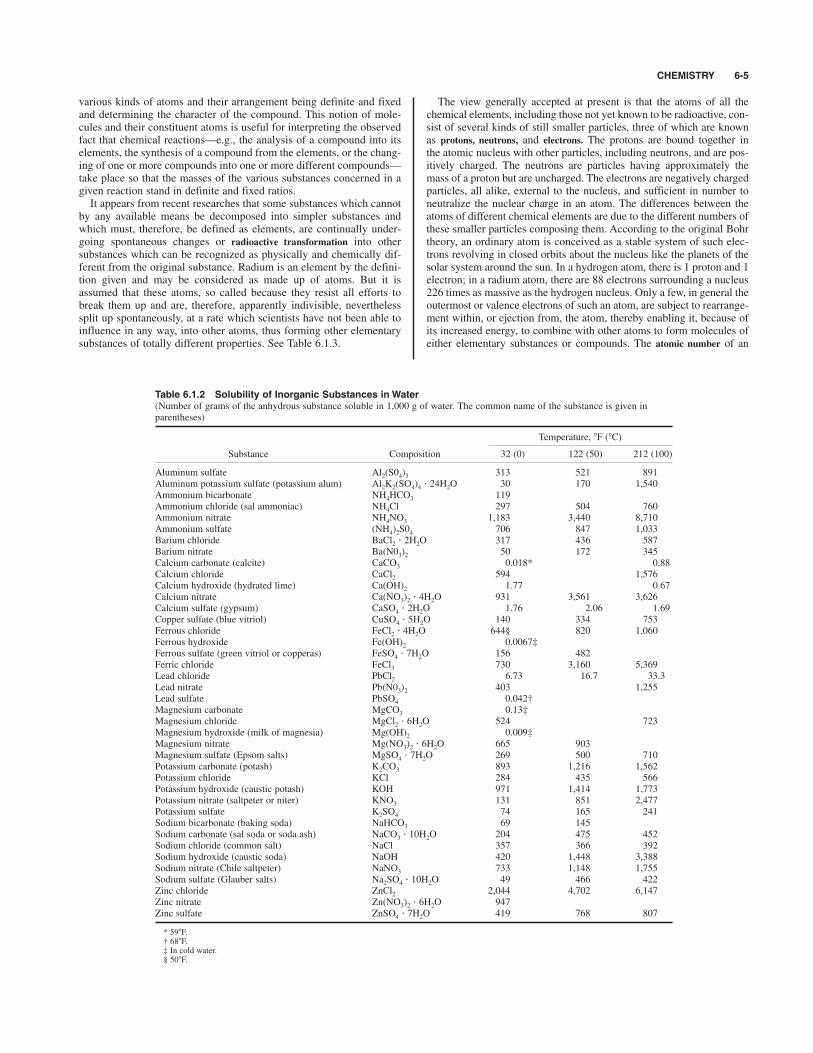
Table 6.1.2 Solubility of Inorganic Substances in Water(Number of grams of the anhydrous substance soluble in 1,000 g of water. The common name of the substance is given inparentheses)
Temperature, 8F (8C)
Substance Composition 32 (0) 122 (50) 212 (100)
Aluminum sulfate Al2(S04)3 313 521 891Aluminum potassium sulfate (potassium alum) Al2K2(SO4)4 " 24H2O 30 170 1,540Ammonium bicarbonate NH4HCO3 119Ammonium chloride (sal ammoniac) NH4Cl 297 504 760Ammonium nitrate NH4NO3 1,183 3,440 8,710Ammonium sulfate (NH4)2S04 706 847 1,033Barium chloride BaCl2 " 2H2O 317 436 587Barium nitrate Ba(N03)2 50 172 345Calcium carbonate (calcite) CaCO3 0.018* 0.88Calcium chloride CaCl2 594 1,576Calcium hydroxide (hydrated lime) Ca(OH)2 1.77 0.67Calcium nitrate Ca(NO3)2 " 4H2O 931 3,561 3,626Calcium sulfate (gypsum) CaSO4 " 2H2O 1.76 2.06 1.69Copper sulfate (blue vitriol) CuSO4 " 5H2O 140 334 753Ferrous chloride FeCl2 " 4H2O 644§ 820 1,060Ferrous hydroxide Fe(OH)2 0.0067‡Ferrous sulfate (green vitriol or copperas) FeSO4 " 7H2O 156 482Ferric chloride FeCl3 730 3,160 5,369Lead chloride PbCl2 6.73 16.7 33.3Lead nitrate Pb(N03)2 403 1,255Lead sulfate PbSO4 0.042†Magnesium carbonate MgCO3 0.13‡Magnesium chloride MgCl2 " 6H2O 524 723Magnesium hydroxide (milk of magnesia) Mg(OH)2 0.009‡Magnesium nitrate Mg(NO3)2 " 6H2O 665 903Magnesium sulfate (Epsom salts) MgSO4 " 7H2O 269 500 710Potassium carbonate (potash) K2CO3 893 1,216 1,562Potassium chloride KCl 284 435 566Potassium hydroxide (caustic potash) KOH 971 1,414 1,773Potassium nitrate (saltpeter or niter) KNO3 131 851 2,477Potassium sulfate K2SO4 74 165 241Sodium bicarbonate (baking soda) NaHCO3 69 145Sodium carbonate (sal soda or soda ash) NaCO3 " 10H2O 204 475 452Sodium chloride (common salt) NaCl 357 366 392Sodium hydroxide (caustic soda) NaOH 420 1,448 3,388Sodium nitrate (Chile saltpeter) NaNO3 733 1,148 1,755Sodium sulfate (Glauber salts) Na2SO4 " 10H2O 49 466 422Zinc chloride ZnCl2 2,044 4,702 6,147Zinc nitrate Zn(NO3)2 " 6H2O 947Zinc sulfate ZnSO4 " 7H2O 419 768 807
* 598F.† 688F.‡ In cold water.§ 508F.
6-6
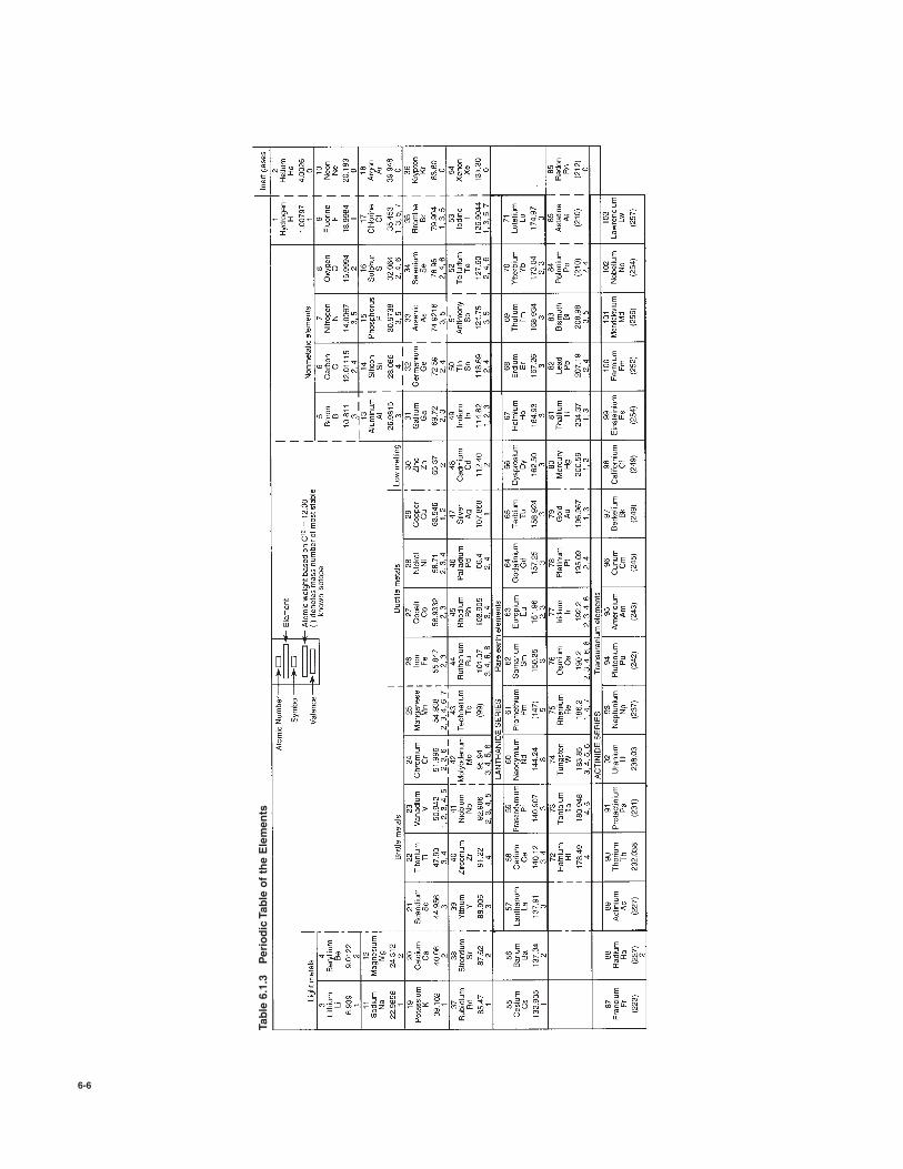
Table 6.1.3
Periodic Table of the Elements

SPECIFIC GRAVITIES AND DENSITIES AND OTHER PHYSICAL DATA 6-7
element is the number of excess positive charges on the nucleus of theatom. The essential feature that distinguishes one element from anotheris this charge of the nucleus. It also determines the position of the ele-ment in the periodic table. Modern researches have shown the existenceof isotopes, that is, two or more species of atoms having the same atom-ic number and thus occupying the same place in the periodic system, butdiffering somewhat in atomic weight. These isotopes are chemicallyidentical and are merely different species of the same chemical element.Most of the ordinary inactive elements have been shown to consist of amixture of isotopes. This convenient atomic model should be regardedas only a working hypothesis for coordinating a number of phenomenaabout which much yet remains to be known. Calculation of the Percentage Composition of Substances Add
the atomic weights of the elements in the compound to obtain its molec-ular weight. Multiply the atomic weight of the element to be calculatedby the number of atoms present (indicated in the formula by a subscriptnumber) and by 100, and divide by the molecular weight of the com-pound. For example, hematite iron ore (Fe2O3) contains 69.94 percentof iron by weight, determined as follows: Molecular weight of Fe2O3 (55.84 # 2) $ (16 # 3) 159.68. Percentage of iron in compound (55.84 # 2) # 100/159.68 69.94.
SPECIFIC GRAVITIES AND DENSITIES AND OTHER PHYSICAL DATA
Table 6.1.5 Approximate Specific Gravities and Densities(Water at 398F and normal atmospheric pressure taken as unity) Formore detailed data on any material, see the section dealing with theproperties of that material. Data given are for usual room temperatures.
SpecificAvg density
Substance gravity lb/ft3 kg/m3
Metals, alloys, ores*
Aluminum, cast-hammered 2.55–2.80 165 2,643Brass, cast-rolled 8.4–8.7 534 8,553Bronze, aluminum 7.7 481 7,702Bronze, 7.9–14% Sn 7.4–8.9 509 8,153Bronze, phosphor 8.88 554 8,874Copper, cast-rolled 8.8–8.95 556 8,906Copper ore, pyrites 4.1–4.3 262 4,197German silver 8.58 536 8,586Gold, cast-hammered 19.25–19.35 1,205 19,300Gold coin (U.S.) 17.18–17.2 1,073 17,190Iridium 21.78–22.42 1,383 22,160Iron, gray cast 7.03–7.13 442 7,079Iron, cast, pig 7.2 450 7,207Iron, wrought 7.6–7.9 485 7,658Iron, spiegeleisen 7.5 468 7,496Iron, ferrosilicon 6.7–7.3 437 6,984Iron ore, hematite 5.2 325 5,206Iron ore, limonite 3.6–4.0 237 3,796Iron ore, magnetite 4.9–5.2 315 5,046Iron slag 2.5–3.0 172 2,755Lead 11.34 710 11,370Lead ore, galena 7.3–7.6 465 7,449Manganese 7.42 475 7,608Manganese ore, pyrolusite 3.7–4.6 259 4,149Mercury 13.546 847 13,570
Table 6.1.5 Approximate Specific Gravities and Densities (Continued )
SpecificAvg density
Substance gravity lb/ft3 kg/m3
Monel metal, rolled 8.97 555 8,688Nickel 8.9 537 8,602Platinum, cast-hammered 21.5 1,330 21,300Silver, cast-hammered 10.4–10.6 656 10,510Steel, cold-drawn 7.83 489 7,832Steel, machine 7.80 487 7,800Steel, tool 7.70–7.73 481 7,703Tin, cast-hammered 7.2–7.5 459 7,352Tin ore, cassiterite 6.4–7.0 418 6,695Tungsten 19.22 1,200 18,820Uranium 18.7 1,170 18,740Zinc, cast-rolled 6.9–7.2 440 7,049Zinc, ore, blende 3.9–4.2 253 4,052
Various solids
Cereals, oats, bulk 0.41 26 417Cereals, barley, bulk 0.62 39 625Cereals, corn, rye, bulk 0.73 45 721Cereals, wheat, bulk 0.77 48 769Cordage (natural fiber) 1.2–1.5 85 1,360Cordage (plastic) 0.9–1.3 69 1,104Cork 0.22–0.26 15 240Cotton, flax, hemp 1.47–1.50 93 1,491Fats 0.90–0.97 58 925Flour, loose 0.40–0.50 28 448Flour, pressed 0.70–0.80 47 753Glass, common 2.40–2.80 162 2,595Glass, plate or crown 2.45–2.72 161 2,580Glass, crystal 2.90–3.00 184 1,950Glass, flint 3.2–4.7 247 3,960Hay and straw, bales 0.32 20 320Leather 0.86–1.02 59 945Paper 0.70–1.15 58 929Plastics (see Sec. 6.12)Potatoes, piled 0.67 44 705Rubber, caoutchouc 0.92–0.96 59 946Rubber goods 1.0–2.0 94 1,506Salt, granulated, piled 0.77 48 769Saltpeter 2.11 132 2,115Starch 1.53 96 1,539Sulfur 1.93–2.07 125 2,001Wool 1.32 82 1,315
Timber, air-dry
Apple 0.66–0.74 44 705Ash, black 0.55 34 545Ash, white 0.64–0.71 42 973Birch, sweet, yellow 0.71–0.72 44 705Cedar, white, red 0.35 22 352Cherry, wild red 0.43 27 433Chestnut 0.48 30 481Cypress 0.45–0.48 29 465Fir, Douglas 0.48–0.55 32 513Fir, balsam 0.40 25 401Elm, white 0.56 35 561
Table 6.1.4 Solubility of Gases in Water(By volume at atmospheric pressure)
t, 8F (8C) t, 8F (8C)
32 (0) 68 (20) 212 (100) 32 (0) 68 (20) 212 (100)
Air 0.032 0.020 0.012 Hydrogen 0.023 0.020 0.018Acetylene 1.89 1.12 Hydrogen sulfide 5.0 2.8 0.87Ammonia 1,250 700 Hydrochloric acid 560 480Carbon dioxide 1.87 0.96 0.26 Nitrogen 0.026 0.017 0.0105Carbon monoxide 0.039 0.025 Oxygen 0.053 0.034 0.185Chlorine 5.0 2.5 0.00 Sulfuric acid 87 43
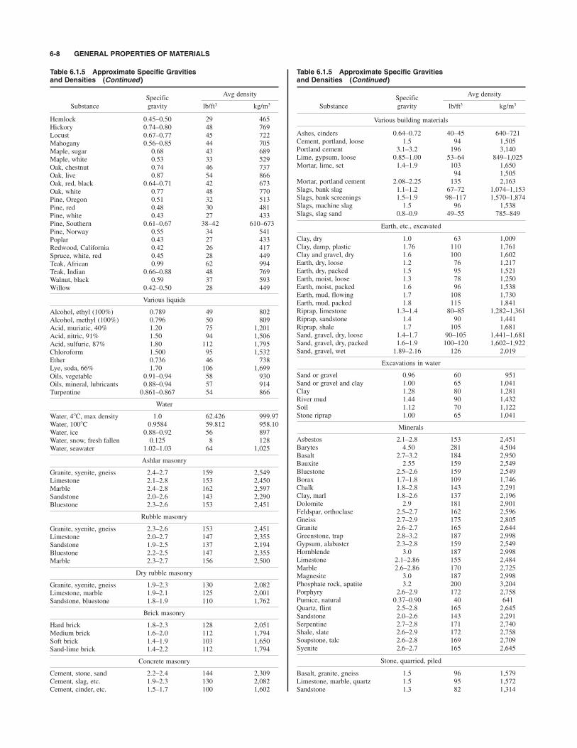
Table 6.1.5 Approximate Specific Gravities and Densities (Continued )
SpecificAvg density
Substance gravity lb/ft3 kg/m3
Hemlock 0.45–0.50 29 465Hickory 0.74–0.80 48 769Locust 0.67–0.77 45 722Mahogany 0.56–0.85 44 705Maple, sugar 0.68 43 689Maple, white 0.53 33 529Oak, chestnut 0.74 46 737Oak, live 0.87 54 866Oak, red, black 0.64–0.71 42 673Oak, white 0.77 48 770Pine, Oregon 0.51 32 513Pine, red 0.48 30 481Pine, white 0.43 27 433Pine, Southern 0.61–0.67 38–42 610–673Pine, Norway 0.55 34 541Poplar 0.43 27 433Redwood, California 0.42 26 417Spruce, white, red 0.45 28 449Teak, African 0.99 62 994Teak, Indian 0.66–0.88 48 769Walnut, black 0.59 37 593Willow 0.42–0.50 28 449
Various liquids
Alcohol, ethyl (100%) 0.789 49 802Alcohol, methyl (100%) 0.796 50 809Acid, muriatic, 40% 1.20 75 1,201Acid, nitric, 91% 1.50 94 1,506Acid, sulfuric, 87% 1.80 112 1,795Chloroform 1.500 95 1,532Ether 0.736 46 738Lye, soda, 66% 1.70 106 1,699Oils, vegetable 0.91–0.94 58 930Oils, mineral, lubricants 0.88–0.94 57 914Turpentine 0.861–0.867 54 866
Water
Water, 48C, max density 1.0 62.426 999.97Water, 1008C 0.9584 59.812 958.10Water, ice 0.88–0.92 56 897Water, snow, fresh fallen 0.125 8 128Water, seawater 1.02–1.03 64 1,025
Ashlar masonry
Granite, syenite, gneiss 2.4–2.7 159 2,549Limestone 2.1–2.8 153 2,450Marble 2.4–2.8 162 2,597Sandstone 2.0–2.6 143 2,290Bluestone 2.3–2.6 153 2,451
Rubble masonry
Granite, syenite, gneiss 2.3–2.6 153 2,451Limestone 2.0–2.7 147 2,355Sandstone 1.9–2.5 137 2,194Bluestone 2.2–2.5 147 2,355Marble 2.3–2.7 156 2,500
Dry rubble masonry
Granite, syenite, gneiss 1.9–2.3 130 2,082Limestone, marble 1.9–2.1 125 2,001Sandstone, bluestone 1.8–1.9 110 1,762
Brick masonry
Hard brick 1.8–2.3 128 2,051Medium brick 1.6–2.0 112 1,794Soft brick 1.4–1.9 103 1,650Sand-lime brick 1.4–2.2 112 1,794
Concrete masonry
Cement, stone, sand 2.2–2.4 144 2,309Cement, slag, etc. 1.9–2.3 130 2,082Cement, cinder, etc. 1.5–1.7 100 1,602
Table 6.1.5 Approximate Specific Gravities and Densities (Continued )
SpecificAvg density
Substance gravity lb/ft3 kg/m3
Various building materials
Ashes, cinders 0.64–0.72 40–45 640–721Cement, portland, loose 1.5 94 1,505Portland cement 3.1–3.2 196 3,140Lime, gypsum, loose 0.85–1.00 53–64 849–1,025Mortar, lime, set 1.4–1.9 103 1,650
94 1,505Mortar, portland cement 2.08–2.25 135 2,163Slags, bank slag 1.1–1.2 67–72 1,074–1,153Slags, bank screenings 1.5–1.9 98–117 1,570–1,874Slags, machine slag 1.5 96 1,538Slags, slag sand 0.8–0.9 49–55 785–849
Earth, etc., excavated
Clay, dry 1.0 63 1,009Clay, damp, plastic 1.76 110 1,761Clay and gravel, dry 1.6 100 1,602Earth, dry, loose 1.2 76 1,217Earth, dry, packed 1.5 95 1,521Earth, moist, loose 1.3 78 1,250Earth, moist, packed 1.6 96 1,538Earth, mud, flowing 1.7 108 1,730Earth, mud, packed 1.8 115 1,841Riprap, limestone 1.3–1.4 80–85 1,282–1,361Riprap, sandstone 1.4 90 1,441Riprap, shale 1.7 105 1,681Sand, gravel, dry, loose 1.4–1.7 90–105 1,441–1,681Sand, gravel, dry, packed 1.6–1.9 100–120 1,602–1,922Sand, gravel, wet 1.89–2.16 126 2,019
Excavations in water
Sand or gravel 0.96 60 951Sand or gravel and clay 1.00 65 1,041Clay 1.28 80 1,281River mud 1.44 90 1,432Soil 1.12 70 1,122Stone riprap 1.00 65 1,041
Minerals
Asbestos 2.1–2.8 153 2,451Barytes 4.50 281 4,504Basalt 2.7–3.2 184 2,950Bauxite 2.55 159 2,549Bluestone 2.5–2.6 159 2,549Borax 1.7–1.8 109 1,746Chalk 1.8–2.8 143 2,291Clay, marl 1.8–2.6 137 2,196Dolomite 2.9 181 2,901Feldspar, orthoclase 2.5–2.7 162 2,596Gneiss 2.7–2.9 175 2,805Granite 2.6–2.7 165 2,644Greenstone, trap 2.8–3.2 187 2,998Gypsum, alabaster 2.3–2.8 159 2,549Hornblende 3.0 187 2,998Limestone 2.1–2.86 155 2,484Marble 2.6–2.86 170 2,725Magnesite 3.0 187 2,998Phosphate rock, apatite 3.2 200 3,204Porphyry 2.6–2.9 172 2,758Pumice, natural 0.37–0.90 40 641Quartz, flint 2.5–2.8 165 2,645Sandstone 2.0–2.6 143 2,291Serpentine 2.7–2.8 171 2,740Shale, slate 2.6–2.9 172 2,758Soapstone, talc 2.6–2.8 169 2,709Syenite 2.6–2.7 165 2,645
Stone, quarried, piled
Basalt, granite, gneiss 1.5 96 1,579Limestone, marble, quartz 1.5 95 1,572Sandstone 1.3 82 1,314
6-8 GENERAL PROPERTIES OF MATERIALS
SPECIFIC GRAVITIES AND DENSITIES AND OTHER PHYSICAL DATA 6-9
Table 6.1.5 Approximate Specific Gravities and Densities (Continued )
SpecificAvg density
Substance gravity lb/ft3 kg/m3
Shale 1.5 92 1,474Greenstone, hornblend 1.7 107 1,715
Bituminous substances
Asphaltum 1.1–1.5 81 1,298Coal, anthracite 1.4–1.8 97 1,554Coal, bituminous 1.2–1.5 84 1,346Coal, lignite 1.1–1.4 78 1,250Coal, peat, turf, dry 0.65–0.85 47 753Coal, charcoal, pine 0.28–0.44 23 369Coal, charcoal, oak 0.47–0.57 33 481Coal, coke 1.0–1.4 75 1,201Graphite 1.64–2.7 135 2,163Paraffin 0.87–0.91 56 898Petroleum 0.87 54 856Petroleum, refined 0.78–0.82 50 801(kerosene)Petroleum, benzine 0.73–0.75 46 737Petroleum, gasoline 0.70–0.75 45 721Pitch 1.07–1.15 69 1,105Tar, bituminous 1.20 75 1,201
Coal and coke, piled
Coal, anthracite 0.75–0.93 47–58 753–930Coal, bituminous, lignite 0.64–0.87 40–54 641–866Coal, peat, turf 0.32–0.42 20–26 320–417Coal, charcoal 0.16–0.23 10–14 160–224Coal, coke 0.37–0.51 23–32 369–513
Gases (see Sec. 4)
* See also Sec. 6.4.
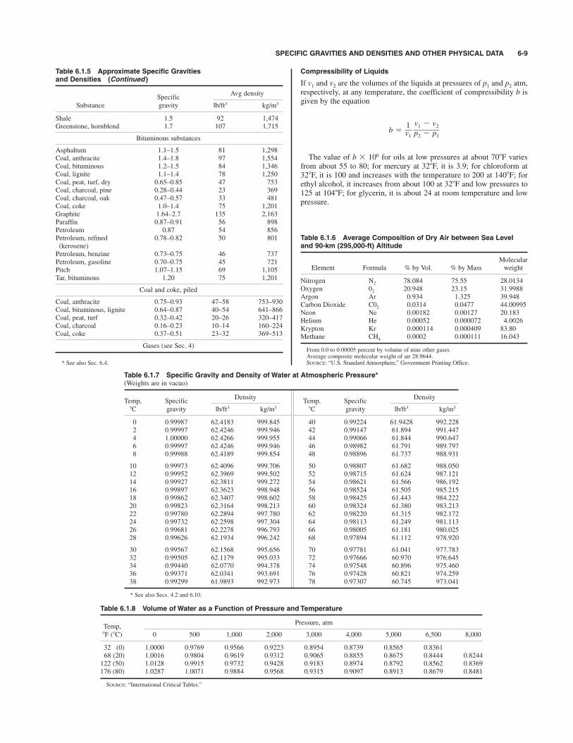
Compressibility of Liquids
If v1 and v2 are the volumes of the liquids at pressures of p1 and p2 atm,respectively, at any temperature, the coefficient of compressibility b isgiven by the equation
The value of b # 106 for oils at low pressures at about 708F variesfrom about 55 to 80; for mercury at 328F, it is 3.9; for chloroform at328F, it is 100 and increases with the temperature to 200 at 1408F; forethyl alcohol, it increases from about 100 at 328F and low pressures to125 at 1048F; for glycerin, it is about 24 at room temperature and lowpressure.
Table 6.1.6 Average Composition of Dry Air between Sea Leveland 90-km (295,000-ft) Altitude
MolecularElement Formula % by Vol. % by Mass weight
Nitrogen N2 78.084 75.55 28.0134Oxygen 02 20.948 23.15 31.9988Argon Ar 0.934 1.325 39.948Carbon Dioxide C02 0.0314 0.0477 44.00995Neon Ne 0.00182 0.00127 20.183Helium He 0.00052 0.000072 4.0026Krypton Kr 0.000114 0.000409 83.80Methane CH4 0.0002 0.000111 16.043
From 0.0 to 0.00005 percent by volume of nine other gases.Average composite molecular weight of air 28.9644.SOURCE: “U.S. Standard Atmosphere,” Government Printing Office.
b 51v1
v1 2 v2p2 2 p1
Table 6.1.7 Specific Gravity and Density of Water at Atmospheric Pressure*(Weights are in vacuo)
Temp, SpecificDensity
Temp, SpecificDensity
8C gravity lb/ft3 kg/m3 8C gravity lb/ft3 kg/m3
0 0.99987 62.4183 999.845 40 0.99224 61.9428 992.2282 0.99997 62.4246 999.946 42 0.99147 61.894 991.4474 1.00000 62.4266 999.955 44 0.99066 61.844 990.6476 0.99997 62.4246 999.946 46 0.98982 61.791 989.7978 0.99988 62.4189 999.854 48 0.98896 61.737 988.931
10 0.99973 62.4096 999.706 50 0.98807 61.682 988.05012 0.99952 62.3969 999.502 52 0.98715 61.624 987.12114 0.99927 62.3811 999.272 54 0.98621 61.566 986.19216 0.99897 62.3623 998.948 56 0.98524 61.505 985.21518 0.99862 62.3407 998.602 58 0.98425 61.443 984.22220 0.99823 62.3164 998.213 60 0.98324 61.380 983.21322 0.99780 62.2894 997.780 62 0.98220 61.315 982.17224 0.99732 62.2598 997.304 64 0.98113 61.249 981.11326 0.99681 62.2278 996.793 66 0.98005 61.181 980.02528 0.99626 62.1934 996.242 68 0.97894 61.112 978.920
30 0.99567 62.1568 995.656 70 0.97781 61.041 977.78332 0.99505 62.1179 995.033 72 0.97666 60.970 976.64534 0.99440 62.0770 994.378 74 0.97548 60.896 975.46036 0.99371 62.0341 993.691 76 0.97428 60.821 974.25938 0.99299 61.9893 992.973 78 0.97307 60.745 973.041
* See also Secs. 4.2 and 6.10.
Table 6.1.8 Volume of Water as a Function of Pressure and Temperature
Temp,Pressure, atm
8F (8C) 0 500 1,000 2,000 3,000 4,000 5,000 6,500 8,000
32 (0) 1.0000 0.9769 0.9566 0.9223 0.8954 0.8739 0.8565 0.836168 (20) 1.0016 0.9804 0.9619 0.9312 0.9065 0.8855 0.8675 0.8444 0.8244122 (50) 1.0128 0.9915 0.9732 0.9428 0.9183 0.8974 0.8792 0.8562 0.8369176 (80) 1.0287 1.0071 0.9884 0.9568 0.9315 0.9097 0.8913 0.8679 0.8481
SOURCE: “International Critical Tables.”

6-10
Table 6.1.9
Basic Properties of Several Metals
(Staff contribution)*
Coefficient
of linear
thermal
Thermal
Specific
Approx
Modulus of
Ultimate
Density,†
expansion,‡
conductivity,
heat,‡
melting
elasticity,
Poisson’s
Yield stress,
stress,
Elongation,
Material
g/cm3
in/(in"8F)#10%6
Btu/(h"ft"8F)
Btu/(lb "
8F)
temp, 8F
lb/in2#106
ratio
lb/in2#103
lb/in2#103
%
Aluminum 2024-T3
2.77
12.6
110
0.23
940
10.6
0.33
50
70
18
Aluminum 6061-T6
2.70
13.5
90
0.23
1,080
10.6
0.33
40
45
17
Aluminum 7079-T6
2.74
13.7
70
0.23
900
10.4
0.33
68
78
14
Beryllium, QMV
1.85
6.4–10.2
85
0.45
2,340
40–44
0.024–0.030
27–38
33–51
1–3.5
Copper, pure
8.90
9.2
227
0.092
1,980
17.0
0.32
See“Metals Handbook”
Gold, pure
19.32
172
0.031
1,950
10.8
0.42
18
30
Lead, pure
11.34
29.3
21.4
0.031
620
2.0
0.40–0.45
1.3
2.6
20–50
Magnesium AZ31B-H24 (sheet)
1.77
14.5
55
0.25
1,100
6.5
0.35
22
37
15
Magnesium HK31A-H24
1.79
14.0
66
0.13
1,100
6.4
0.35
29
37
8Molybdenum, wrought
10.3
3.0
83
0.07
4,730
40.0
0.32
80
120–200
Small
Nickle, pure
8.9
7.2
53
0.11
2,650
32.0
0.31§
See“Metals Handbook”
Platinum
21.45
5.0
40
0.031
3,217
21.3
0.39
20–24
35–40
Plutonium, alpha phase
19.0–19.7
30.0
4.8
0.034
1,184
14.0
0.15–0.21
40
60
Small
Silver, pure
10.5
11.0
241
0.056
1,760
10–11
0.37
18
48
Steel, AISI C1020 (hot-worked)
7.85
6.3
27
0.10
2,750
29–30
0.29
48
65
36
Steel, AISI 304 (sheet)
8.03
9.9
9.4
0.12
2,600
28
0.29
39
87
65
Tantalum
16.6
3.6
31
0.03
5,425
27.0
0.35
50–145
1–40
Thorium, induction melt
11.6
6.95
21.7
0.03
3,200
7–10
0.27
21
32
34
Titanium, B 120VCA (aged)
4.85
5.2
4.3
0.13
3,100
14.8
0.3
190
200
9Tungesten
19.3
2.5
95
0.033
6,200
50
0.28
18–600
1–3
Uranium D-38
18.97
4.0–8.0
17
0.028
2,100
24
0.21
28
56
4
Room-temperature properties are given. For further information, consult the “Metals Handbook” or a manufacturer’s publication.
* Compiled by Anders Lundberg, University of California, and reproduced by permission.
† To obtain the preferred density units, kg/m
3, multiply these values by 1,000.
‡ See also Tables 6.1.10and 6.1.11.
§ At 258C.
SPECIFIC GRAVITIES AND DENSITIES AND OTHER PHYSICAL DATA 6-11
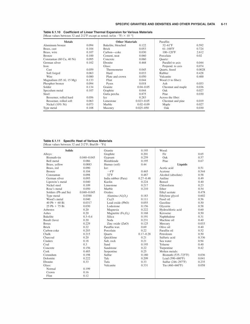
Table 6.1.10 Coefficient of Linear Thermal Expansion for Various Materials[Mean values between 32 and 2128F except as noted; in/(in " 8F) # 10%4]
Metals Other Materials Paraffin:Aluminum bronze 0.094 Bakelite, bleached 0.122 32–618F 0.592Brass, cast 0.104 Brick 0.053 61–1008F 0.724Brass, wire 0.107 Carbon—coke 0.030 100–1208F 2.612Bronze 0.100 Cement, neat 0.060 Porcelain 0.02Constantan (60 Cu, 40 Ni) 0.095 Concrete 0.060 Quartz:German silver 0.102 Ebonite 0.468 Parallel to axis 0.044Iron: Glass: Perpend. to axis 0.074Cast 0.059 Thermometer 0.045 Quarts, fused 0.0028Soft forged 0.063 Hard 0.033 Rubber 0.428Wire 0.080 Plate and crown 0.050 Vulcanite 0.400
Magnalium (85 Al, 15 Mg) 0.133 Flint 0.044 Wood (II to fiber):Phosphor bronze 0.094 Pyrex 0.018 Ash 0.053Solder 0.134 Granite 0.04–0.05 Chestnut and maple 0.036Speculum metal 0.107 Graphite 0.044 Oak 0.027Steel: Gutta percha 0.875 Pine 0.030Bessemer, rolled hard 0.056 Ice 0.283 Across the fiber:Bessemer, rolled soft 0.063 Limestone 0.023–0.05 Chestnut and pine 0.019Nickel (10% Ni) 0.073 Marble 0.02–0.09 Maple 0.027
Type metal 0.108 Masonry 0.025–050 Oak 0.030
Table 6.1.11 Specific Heat of Various Materials[Mean values between 32 and 2128F; Btu/(lb " 8F)]
Solids Granite 0.195 Wood:Alloys: Graphite 0.201 Fir 0.65Bismuth-tin 0.040–0.045 Gypsum 0.259 Oak 0.57Bell metal 0.086 Hornblende 0.195 Pine 0.67Brass, yellow 0.0883 Humus (soil) 0.44 Liquids
Brass, red 0.090 Ice: Acetic acid 0.51Bronze 0.104 %48F 0.465 Acetone 0.544Constantan 0.098 328F 0.487 Alcohol (absolute) 0.58German silver 0.095 India rubber (Para) 0.27–0.48 Aniline 0.49Lipowits’s metal 0.040 Kaolin 0.224 Bensol 0.40Nickel steel 0.109 Limestone 0.217 Chloroform 0.23Rose’s metal 0.050 Marble 0.210 Ether 0.54Solders (Pb and Sn) 0.040–0.045 Oxides: Ethyl acetate 0.478Type metal 0.0388 Alumina (Al3O2) 0.183 Ethylene glycol 0.602Wood’s metal 0.040 Cu2O 0.111 Fusel oil 0.5640 Pb $ 60 Bi 0.0317 Lead oxide (PbO) 0.055 Gasoline 0.5025 Pb $ 75 Bi 0.030 Lodestone 0.156 Glycerin 0.58
Asbestos 0.20 Magnesia 0.222 Hydrochloric acid 0.60Ashes 0.20 Magnetite (Fe3O4) 0.168 Kerosene 0.50Bakelite 0.3–0.4 Silica 0.191 Naphthalene 0.31Basalt (lava) 0.20 Soda 0.231 Machine oil 0.40Borax 0.229 Zinc oxide (ZnO) 0.125 Mercury 0.033Brick 0.22 Paraffin wax 0.69 Olive oil 0.40Carbon-coke 0.203 Porcelain 0.22 Paraffin oil 0.52Chalk 0.215 Quarts 0.17–0.28 Petroleum 0.50Charcoal 0.20 Quicklime 0.21 Sulfuric acid 0.336Cinders 0.18 Salt, rock 0.21 Sea water 0.94Coal 0.3 Sand 0.195 Toluene 0.40Concrete 0.156 Sandstone 0.22 Turpentine 0.42Cork 0.485 Serpentine 0.25 Molten metals:Corundum 0.198 Sulfur 0.180 Bismuth (535–7258F) 0.036Dolomite 0.222 Talc 0.209 Lead (590–6808F) 0.041Ebonite 0.33 Tufa 0.33 Sulfur (246–2978F) 0.235Glass: Vulcanite 0.331 Tin (460–6608F) 0.058Normal 0.199Crown 0.16Flint 0.12

REFERENCES: “Metals Handbook,” ASM International, latest ed., ASTMStandards, pt. 1. SAE Handbook. “Steel Products Manual,” AISI. “Making,Shaping and Treating of Steel,” AISE, latest ed.
CLASSIFICATION OF IRON AND STEEL
Iron (Fe) is not a high-purity metal commercially but contains otherchemical elements which have a large effect on its physical andmechanical properties. The amount and distribution of these elementsare dependent upon the method of manufacture. The most importantcommercial forms of iron are listed below.
Pig iron is the product of the blast furnace and is made by the reduc-tion of iron ore.
Cast iron is an alloy of iron containing enough carbon to have a lowmelting temperature and which can be cast to close to final shape. It isnot generally capable of being deformed before entering service.
Gray cast iron is an iron which, as cast, has combined carbon (in theform of cementite, Fe3C) not in excess of a eutectoid percentage—thebalance of the carbon occurring as graphite flakes. The term “gray iron”is derived from the characteristic gray fracture of this metal.
White cast iron contains carbon in the combined form. The presenceof cementite or iron carbide (Fe3C) makes this metal hard and brittle,and the absence of graphite gives the fracture a white color.
Malleable cast iron is an alloy in which all the combined carbon in aspecial white cast iron has been changed to free or temper carbon bysuitable heat treatment.
Nodular (ductile) cast iron is produced by adding alloys of magnesiumor cerium to molten iron. These additions cause the graphite to forminto small nodules, resulting in a higher-strength, ductile iron.
Ingot iron, electrolytic iron (an iron-hydrogen alloy), and wrought iron areterms for low-carbon materials which are no longer serious items ofcommerce but do have considerable historical interest.
Steel is an alloy predominantly of iron and carbon, usually containingmeasurable amounts of manganese, and often readily formable.
Carbon steel is steel that owes its distinctive properties chiefly to thecarbon it contains.
Alloy steel is steel that owes its distinctive properties chiefly to someelement or elements other than carbon, or jointly to such other elementsand carbon. Some alloy steels necessarily contain an important per-centage of carbon, even as much as 1.25 percent. There is no completeagreement about where to draw the line between the alloy steels and thecarbon steels.
Basic oxygen steel and electric-furnace steel are steels made by the basicoxygen furnace and electric furnace processes, irrespective of carboncontent; the effective individual alloy content in engineering steels canrange from 0.05 percent up to 3 percent, with a total usually less than5 percent. Open-hearth and Bessemer steelmaking are no longer prac-ticed in the United States.Iron ore is reduced in a blast furnace to form pig iron, which is the
raw material for practically all iron and steel products. Formerly, nearly90 percent of the iron ore used in the United States came from the LakeSuperior district; the ore had the advantages of high quality and thecheapness with which it could be mined and transported by way of theGreat Lakes. With the rise of global steelmaking and the availability ofhigh-grade ores and pellets (made on a large scale from low-grade ores)from many sources, the choice of feedstock becomes an economicdecision.The modern blast furnace consists of a vertical shaft up to 10 m or
40 ft in diameter and over 30 m (100 ft) high containing a descendingcolumn of iron ore, coke, and limestone and a large volume of ascending
hot gas. The gas is produced by the burning of coke in the hearth of thefurnace and contains about 34 percent carbon monoxide. This gasreduces the iron ore to metallic iron, which melts and picks up consid-erable quantities of carbon, manganese, phosphorus, sulfur, and sili-con. The gangue (mostly silica) of the iron ore and the ash in the cokecombine with the limestone to form the blast-furnace slag. The pig ironand slag are drawn off at intervals from the hearth through the ironnotch and cinder notch, respectively. Some of the larger blast furnacesproduce around 10,000 tons of pig iron per day. The blast furnace pro-duces a liquid product for one of three applications: (1) the hugemajority passes to the steelmaking process for refining; (2) pig iron isused in foundries for making castings; and (3) ferroalloys, which con-tain a considerable percentage of another metallic element, are used asaddition agents in steelmaking. Compositions of commercial pig ironsand two ferroalloys (ferromanganese and ferrosilicon) are listed inTable 6.2.1.Physical Constants of Unalloyed Iron Some physical properties of
iron and even its dilute alloys are sensitive to small changes in compo-sition, grain size, or degree of cold work. The following are reasonablyaccurate for “pure” iron at or near room temperature; those with anasterisk are sensitive to these variables perhaps by 10 percent or more.Those with a dagger (†) depend measurably on temperature; moreextended tables should be consulted.Specific gravity, 7.866; melting point, 1,5368C (2,7978F); heat of
fusion 277 kJ/kg (119 Btu/lbm); thermal conductivity 80.2 W/(m " C)[557 Btu/(h " ft2 " in " 8F)*†; thermal coefficient of expansion 12 #10%6/8C (6.7 # 10%6/8F)†; electrical resistivity 9.7 m& " cm*†; andtemperature coefficient of electrical resistance 0.0065/8C (0.0036/8F).†Mechanical Properties Representative mechanical properties of
annealed low-carbon steel (often similar to the former ingot iron) are asfollows: yield strength 130 to 150 MPa (20 to 25 ksi); tensile strength260 to 300 MPa (40 to 50 ksi); elongation 20 to 45 percent in 2 in;reduction in area of 60 to 75 percent; Brinell hardness 65 to 100. Thesefigures are at best approximate and depend on composition (especiallytrace additives) and processing variables. For more precise data, suppli-ers or broader databases should be consulted.Young’s modulus for ingot iron is 202,000 MPa (29,300,000 lb/in2)
in both tension and compression, and the shear modulus is 81,400 MPa(11,800,000 lb/in2). Poisson’s ratio is 0.28. The effect of cold rollingon the tensile strength, yield strength, elongation, and shape of thestressstrain curve is shown in Fig. 6.2.1, which is for Armco ingot ironbut would not be substantially different for other low-carbon steels.Uses Low-carbon materials weld evenly and easily in all processes,
can be tailored to be readily paintable and to be enameled, and withother treatments make an excellent low-cost soft magnetic material withhigh permeability and low coercive force for mass-produced motorsand transformers. Other uses, usually after galvanizing, include cul-verts, flumes, roofing, siding, and housing frames; thin plates can beused in oil and water tanks, boilers, gas holders, and various nonde-manding pipes; enameled sheet retains a strong market in ranges, refrig-erators, and other household goods, in spite of challenges from plastics.World Production From about 1970 to 1995, the annual world pro-
duction of steel was remarkably steady at some 800,000,000 tons.Reductions in some major producers (United States, Japan, some Europeancountries, and the collapsing U.S.S.R.) were balanced by the manysmaller countries which began production. The struggle for markets ledto pricing that did not cover production costs and led to internationalpolitical strains. A major impact began in the 1990s as China pushed itsown production from a few tens of million tons toward 300,000,000tons in 2004, pushing world production to over 1 billion tons.
6-12
6.2 IRON AND STEELby Harold W. Paxton

STEEL 6-13
Fig. 6.2.1 Effect of cold rolling on the stress-strain relationship of Armco ingotiron. (Kenyon and Burns.)
The world raw material infrastructure (iron ore, coke, and scrap) wasnot able to react quickly to support this increase, and prices soared;steel prices followed. Recently (2006) long-term ore contracts reflectedlarge price increases, so it appears that for some time steel prices willremain high by historical comparisons. The effects of material substitu-tion are not yet clear, but as end users examine their options more closely,the marketplace will most likely settle the matter.
STEEL
Steel Manufacturing
Steel is produced by the removal of impurities from pig iron in a basicoxygen furnace or an electric furnace.Basic Oxygen Steel This steel is produced by blowing pure
(99 percent) oxygen either vertically under high pressure (1.2 MPa or175 lb/in2) onto the surface of molten pig iron (BOP) or through tuyeresin the base of the vessel (the Q-BOP process). Some facilities use a com-bination depending on local circumstances and product mix. This is anautogenous process that requires no external heat to be supplied. Thefurnaces are similar in shape to the former Bessemer converters butrange in capacity to 275 metric tons (t) (300 net tons) or more. The barrel-shaped furnace or vessel may or may not be closed on the bottom, isopen at the top, and can rotate in a vertical plane about a horizontal axisfor charging and for pouring the finished steel. Selected scrap ischarged into the vessel first, up to 30 percent by weight of the totalcharge. Molten pig iron (often purified from the raw blast-furnace hotmetal to give lower sulfur, phosphorus, and sometimes silicon) ispoured into the vessel. In the Q-BOP, oxygen must be flowing throughthe bottom tuyeres at this time to prevent clogging; further flow servesto refine the charge and carries in fluxes as powders. In the BOPprocess, oxygen is introduced through a water-cooled lance introducedthrough the top of the vessel. Within seconds after the oxygen is turnedon, some iron in the charge is converted to ferrous oxide, which reactsrapidly with the impurities of the charge to remove them from themetal. As soon as reaction starts, limestone is added as a flux. Blowingis continued until the desired degree of purification is attained. Thereactions take place very rapidly, and blowing of a heat is completed in
about 20 min in a 200-net-ton furnace. Because of the speed of theprocess, a computer is used to calculate the charge required for makinga given heat of steel, the rate and duration of oxygen blowing, and toregulate the quantity and timing of additions during the blow and forfinishing the steel. Production rates of well over 270 t per furnace hour(300 net tons) can be attained. The comparatively low investment costand low cost of operation have already made the basic oxygen processthe largest producer of steel in the world, and along with electric fur-naces, it almost completely replaces the basic open hearth as the majorsteelmaking process. No open hearths operate in the United Statestoday. Electric Steel The biggest change in steelmaking over the last 20 years
is the fraction of steel made by remelting scrap in an electric furnace(EF), originally to serve a relatively nondemanding local market, butincreasingly moving up in quality and products to compete with millsusing the blast-furnace/oxygen steelmaking route. The economic compe-tition is fierce and has served to improve choices for customers. In the lastdecade the fraction of steel made in the EF in the United States has goneabove 50 percent by a combination of contraction in blast-furnace (BF)production (no new ones built, retirement of some, and a shortage of suit-able coke) and an increase of total production, which has been met withEFs. At one time, there was concern that some undesirable elements in
scrap that are not eliminated in steelmaking, notably copper and zinc,would increase with remelting cycles. However, the development of alter-native iron units (direct reduced iron, iron carbide, and even pig iron) todilute scrap additions has at least postponed this as an issue.Early processes used three-phase alternating current, but increasingly
the movement is to a single dc electrode with a conducting hearth. Thehigh-power densities necessitate water cooling and improved basicrefractory linings. Scrap is charged into the furnace, which usually con-tains some of the last heat to improve efficiency. Older practices oftenhad a second slag made after the first meltdown and refining by oxygenblowing, but today, final refining takes place outside the melting unit ina ladle furnace, which allows refining, temperature control, and alloy-ing additions to be made without interfering with the next heat. Thematerials are continuously cast including slabs only 50 mm (2 in) thickand casting directly to sheet in the 1- to 2-mm (0.04- to 0.08-in) thick-ness range is passing through the pilot stage.The degree to which electric melting can replace more conventional
methods is of great interest and depends in large part on the availabilityof sufficiently pure scrap at an attractive price and some improvementsin surface quality to be able to make the highest-value products.Advances in EF technology are countered aggressively by new devel-opments and cost control in traditional steelmaking; it may well be adecade or more before the pattern clarifies.The induction furnace is simply a fairly small melting furnace to
which the various metals are added to make the desired alloy, usuallyquite specialized. When steel scrap is used as a charge, it will be a high-grade scrap the composition of which is well known (see also Sec. 7).Ladle Metallurgy One of the biggest contributors to quality in steel
products is the concept of refining liquid steel outside the first meltingunit—BOP, Q-BOP, or EF, none of which is well designed to perform
Table 6.2.1 Types of Pig Iron for Steelmaking and Foundry Use
Chemical composition, %*
Designation Si P Mn C† Principal use
Basic pig, northern 1.50 max 0.400 max 1.01–2.00 3.5–4.4 Basic oxygen steelIn steps of 0.25 0.50
Foundry, northern 3.50 max 0.301–0.700 0.50–1.25 3.0–4.5 A wide variety of castingsIn steps of 0.25 0.25
Foundry, southern 3.50 max 0.700–0.900 0.40–0.75 3.0–4.5 Cast-iron pipeIn steps of 0.25 0.25
Ferromanganese (3 grades) 1.2 max 0.35 max 74–82 7.4 max Addition of manganese to steel or cast ironFerrosilicon (silvery pig) 5.00–17.00 0.300 max 1.00–2.00 1.5 max Addition of silicon to steel or cast iron
* Excerpted from “The Making, Shaping and Treating of Steel,” AISE, 1984; further information in “Steel Products Manual,” AISI, and ASTM Standards, Pt. 1.† Carbon content not specified—for information only. Usually S is 0.05 max (0.06 for ferrosilicon) but S and P for basic oxygen steel are typically much lower today.

the final refining function. In this separate unit, gases in solution (oxy-gen, hydrogen, and, to a lesser extent, nitrogen) can be reduced by vac-uum treatment, carbon can be adjusted to desirable very low levels byreaction with oxygen in solution, alloy elements can be added, the tem-perature can be adjusted, and the liquid steel can be stirred by inertgases to float out inclusions and provide a homogeneous charge to thecontinuous casters which are now virtually ubiquitous. Reducing oxy-gen in solution means a “cleaner” steel (fewer nonmetallic inclusions)and a more efficient recovery of active alloying elements added with apurpose and which otherwise might end up as oxides.Steel Ingots With the advent of continuous casters, ingot casting is
now generally reserved for the production of relatively small volumesof material such as heavy plates and forgings which are too big for cur-rent casters. Ingot casting, apart from being inefficient in that the largevolume change from liquid to solid must be handled by discarding thelarge void space usually at the top of the ingot (the pipe), also has sev-eral other undesirable features caused by the solidification pattern in alarge volume, most notably significant differences in compositionthroughout the piece (segregation) leading to different properties,inclusions formed during solidification, and surface flaws from poormold surfaces, splashing and other practices, which if not properlyremoved lead to defects in finished products (seams, scabs, scale, etc.).Some defects can be removed or attenuated, but others cannot; in gen-eral, with the exception of some very specialized tool and bearingsteels, products from ingots are no longer state-of-the-art unless theyare needed for size.Continuous Casting This concept, which began with Bessemer in
the 1850s, began to be a reliable production tool around 1970 and sincethen has replaced basically all ingot casting. Industrialized countries allcontinuously cast close to 100 percent of their production. Sizes castrange from 2-m (80-in)—or more—by 0.3-m (12-in) slabs down to 0.1-m(4-in) square or round billets. Multiple strands are common where pro-duction volume is important. Many heats of steel can be cast in a con-tinuous string with changes of width possible during operation.Changes of composition are possible in succeeding ladles with a dis-card of the short length of mixed composition.By intensive process control, it is often possible to avoid cooling the
cast slabs to room temperature for inspection, enabling energy savingssince the slabs require less reheating before hot rolling. If for some rea-son the slabs are cooled to room temperature, any surface defects whichmight lead to quality problems can be removed—usually by scarfingwith an oxyacetylene torch or by grinding. Since this represents a yieldloss, there is a real economic incentive to avoid the formation of suchdefects by paying attention to casting practices.
Mechanical Treatment of Steel
Cast steel, in the form of slabs, billets, or bars (these latter two differsomewhat arbitrarily in size) is treated further by various combinationsof hot and cold deformation to produce a finished product for sale fromthe mill. Further treatments by fabricators usually occur before deliveryto the final customer. These treatments have three purposes: (1) tochange the shape by deformation or metal removal to desired toler-ances; (2) to break up—at least partially—the segregation and largegrain sizes inevitably formed during the solidification process and toredistribute the nonmetallic inclusions which are present; and (3) tochange the properties. For example, these may be functional—strengthor toughness—or largely aesthetic, such as reflectivity.These purposes may be separable or in many cases may be acting
simultaneously. An example is hot-rolled sheet or plate in which oftenthe rolling schedule (reductions and temperature of each pass, and thecooling rate after the last reduction) is a critical path to obtain the prop-erties and sizes desired and is often known as “heat treatment on themill.” The development of controls to do this has allowed much highertonnages at attractive prices, and increasing robustness of rolls hasallowed steel to be hot-rolled down to the 1 mm (0.04-in) range, whereit can compete with the more expensive “cold-rolled” material.Most steels are reduced after appropriate heating (to above 1,0008C)
in various multistand hot rolling mills to produce sheet, strip, plate, tubes,
shaped sections, or bars. More specialized deformation, e.g., by hammer
forging, can result in working in more than one direction, with a distri-bution of inclusions which is not extended in one direction. Rolling,e.g., more readily imparts anisotropic properties. Press forging at slowstrain rates changes the worked structure to greater depths and is pre-ferred for high-quality products. The degree of reduction required toeliminate the cast structure varies from 4:1 to 10:1; clearly smallerreductions would be desirable but are currently not usual.The slabs, blooms, and billets from the caster must be reheated in an
atmosphere-controlled furnace to the working temperature, often fromroom temperature, but if practices permit, they may be charged hot tosave energy. Coupling the hot deformation process directly to slabs atthe continuous caster exit is potentially more efficient, but practical dif-ficulties currently limit this to a small fraction of total production.The steel is oxidized during heating to some degree, and this oxida-
tion is removed by a combination of light deformation and high-pressurewater sprays before the principal deformation is applied. There aredifferences in detail between processes, but as a representative example,the conventional production of wide “hot-rolled sheet” ['1.5 m (60 in)]will be discussed.The slab, about 0.3 m (12 in) thick at about 12008C is passed through
a scale breaker and high-pressure water sprays to remove the oxidefilm. It then passes through a set of roughing passes (possibly withsome modest width reduction) to reduce the thickness to just over 25 mm(1 in), the ends are sheared perpendicular to the length to remove irreg-ularities, and finally they are fed into a series of up to seven roll standseach of which creates a reduction of 50 to 10 percent passing along thetrain. Process controls allow each mill stand to run sufficiently fasterthan the previous one to maintain tension and avoid pileups betweenstands. The temperature of the sheet is a balance between heat added bydeformation and that lost by heat transfer, sometimes with interstandwater sprays. Ideally the temperature should not vary between head andtail of the sheet, but this is hard to accomplish. The deformation encourages recrystallization and even some grain
growth between stands; even though the time is short, temperatures arehigh. Emerging from the last stand between 815 and 9508C, the austenite*may or may not recrystallize, depending on the temperature. At highertemperatures, when austenite does recrystallize, the grain size is usual-ly small (often in the 10- to 20-mm range). At lower exit temperaturesaustenite grains are rolled into “pancakes” with the short dimensionoften less than 10 mm. Since several ferrite* grains nucleate from eachaustenite grain during subsequent cooling, the ferrite grain size can beas low as 3 to 6 mm (ASTM 14 to 12). We shall see later that small fer-rite grain sizes are a major contributor to the superior properties oftoday’s carbon steels, which provide good strength and superior tough-ness simultaneously and economically.Some of these steels also incorporate strong carbide* and nitride*
formers in small amounts to provide extra strength from precipitationhardening; the degree to which these are undissolved in austenite dur-ing hot rolling affects recrystallization significantly. The subject is toocomplex to treat briefly here; the interested reader is referred to theASM “Metals Handbook.”After the last pass, the strip may be cooled by programmed water sprays
to between 510 and 7308C so that during coiling, any desired precipitationprocesses may take place in the coiler. The finished coil, usually 2 to 3 mm(0.080 to 0.120 in) thick and sometimes 1.3 to 1.5 mm (0.052 to 0.060 in)thick, which by now has a light oxide coating, is taken off line and eithershippped directly or retained for further processing to make higher value-added products. Depending on composition, typical values of yieldstrength are from 210 up to 380 MPa (30 to 55 ksi), UTS in the range of400 to 550 MPa (58 to 80 ksi), with an elongation in 200 mm (8 in) ofabout 20 percent. The higher strengths correspond to low-alloy steels.About half the sheet produced is sold directly as hot-rolled sheet.
The remainder is further cold-worked after scale removal by picklingand either is sold as cold-worked to various tempers or is recrystal-lized to form a very formable product known as cold-rolled and annealed,
6-14 IRON AND STEEL
* See Fig. 6.2.4 and the discussion thereof.
STEEL 6-15
To make the highest class of formable sheet is a very sophisticatedoperation. After pickling, the sheet is again reduced in a multistand(three, four, or five) mill with great attention paid to tolerances and sur-face finish. Reductions per pass range from 25 to 45 percent in earlypasses to 10 to 30 percent in the last pass. The considerable heat gener-ated necessitates an oil-water mixture to cool and to provide the neces-sary lubrication. The finished coil is degreased prior to annealing.The purpose of annealing is to provide, for the most demanding
applications, pancake-shaped grains after recrystallization of the cold-worked ferrite, in a matrix with a very sharp crystal texture containinglittle or no carbon or nitrogen in solution. The exact metallurgy is com-plex but well understood. Two types of annealing are possible: slowheating, holding, and cooling of coils in a hydrogen atmosphere (boxannealing) lasting several days, or continuous feeding through a furnacewith a computer-controlled time-temperature cycle. The latter is muchquicker but very capital-intensive and requires careful and complexprocess control.As requirements for formability are reduced, production controls can
be relaxed. In order of increasing cost, the series is commercial quality(CQ), drawing quality (DQ), deep drawing quality (DDQ), and extradeep drawing quality (EDDQ). Even more formable steels are possible,but often are not commercially necessary.Some other deformation processes are occasionally of interest, such
as wire drawing, usually done cold, and extrusion, either hot or cold.Hot extrusion for materials that are difficult to work became practicalthrough the employment of a glass lubricant. This method allows thehot extrusion of highly alloyed steels and other exotic alloys subjectedto service at high loads and/or high temperatures.
Constitution and Structure of Steel
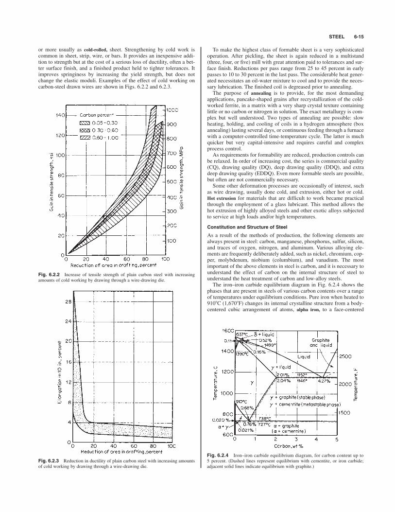
As a result of the methods of production, the following elements arealways present in steel: carbon, manganese, phosphorus, sulfur, silicon,and traces of oxygen, nitrogen, and aluminum. Various alloying ele-ments are frequently deliberately added, such as nickel, chromium, cop-per, molybdenum, niobium (columbium), and vanadium. The mostimportant of the above elements in steel is carbon, and it is necessary tounderstand the effect of carbon on the internal structure of steel tounderstand the heat treatment of carbon and low-alloy steels.The iron–iron carbide equilibrium diagram in Fig. 6.2.4 shows the
phases that are present in steels of various carbon contents over a rangeof temperatures under equilibrium conditions. Pure iron when heated to9108C (1,6708F) changes its internal crystalline structure from a body-centered cubic arrangement of atoms, alpha iron, to a face-centered
or more usually as cold-rolled, sheet. Strengthening by cold work iscommon in sheet, strip, wire, or bars. It provides an inexpensive addi-tion to strength but at the cost of a serious loss of ductility, often a bet-ter surface finish, and a finished product held to tighter tolerances. Itimproves springiness by increasing the yield strength, but does notchange the elastic moduli. Examples of the effect of cold working oncarbon-steel drawn wires are shown in Figs. 6.2.2 and 6.2.3.
Fig. 6.2.2 Increase of tensile strength of plain carbon steel with increasingamounts of cold working by drawing through a wire-drawing die.
Fig. 6.2.3 Reduction in ductility of plain carbon steel with increasing amountsof cold working by drawing through a wire-drawing die.
Fig. 6.2.4 Iron–iron carbide equilibrium diagram, for carbon content up to5 percent. (Dashed lines represent equilibrium with cementite, or iron carbide;adjacent solid lines indicate equilibrium with graphite.)

cubic structure, gamma iron. At 1,3908C (2,5358F), it changes back tothe body-centered cubic structure, delta iron, and at 1,5398C (2,8028F)the iron melts. When carbon is added to iron, it is found that it has onlyslight solid solubility in alpha iron (much less than 0.001 percent atroom temperature at equilibrium). These small amounts of carbon,however, are critically important in many high-tonnage applicationswhere formability is required. On the other hand, gamma iron will holdup to 2.0 percent carbon in solution at 1,1308C (2,0668F). The alphairon containing carbon or any other element in solid solution is calledferrite, and the gamma iron containing elements in solid solution iscalled austenite. Usually when not in solution in the iron, the carbonforms a compound Fe3C (iron carbide) which is extremely hard andbrittle and is known as cementite. Other carbides of iron exist but areonly of interest in rather specialized instances.The temperatures at which the phase changes occur are called
critical points (or temperatures) and, in the diagram, represent equilibri-um conditions. In practice there is a lag in the attainment of equilibrium,and the critical points are found at lower temperatures on cooling andat higher temperatures on heating than those given, the differenceincreasing with the rate of cooling or heating.The various critical points have been designated by the letter A; when
obtained on cooling, they are referred to as Ar, on the heating as Ac. Thesubscripts r and c refer to refroidissement and chauffage, respectively,and reflect the early French contributions to heat treatment. The variouscritical points are distinguished from each other by numbers after theletters, being numbered in the order in which they occur as the temper-ature increases. Ac1 represents the beginning of transformation of fer-rite to austenite on heating; Ac3 the end of transformation of ferrite toaustenite on heating, and Ac4 the change from austenite to delta iron onheating. On cooling, the critical points would be referred to as Ar4, Ar3,and Ar1, respectively. The subscript 2, not mentioned here, refers to amagnetic transformation. The error came about through a misunder-standing of what rules of thermodynamics apply in phase diagrams. Itmust be remembered that the diagram represents the pure iron-iron car-bide system at equilibrium. The varying amounts of impurities in com-mercial steels affect to a considerable extent the position of the curvesand especially the lateral position of the eutectoid point. Carbon steel in equilibrium at room temperature will have present
both ferrite and cementite. The physical properties of ferrite are approx-imately those of pure iron and are characteristic of the metal. Cementiteis itself hard and brittle; its shape, amount, and distribution controlmany of the mechanical properties of steel, as discussed later. The factthat the carbides can be dissolved in austenite is the basis of the heattreatment of steel, since the steel can be heated above the A1 criticaltemperature to dissolve all the carbides, and then suitable coolingthrough the appropriate range will produce a wide and predictable rangeof the desired size and distribution of carbides in the ferrite.If austenite with the eutectoid composition at 0.76 percent carbon
(Fig. 6.2.4) is cooled slowly through the critical temperature, ferrite andcementite are rejected simultaneously, forming alternate plates or lamel-lae. This microstructure is called pearlite, since when polished andetched it has a pearly luster. When examined under a high-power opticalmicroscope, however, the individual plates of cementite often can be dis-tinguished easily. If the austenite contains less carbon than the eutectoidcomposition (i.e., hypoeutectoid compositions), free ferrite will first berejected on slow cooling through the critical temperature until the remain-ing austenite reaches eutectoid composition, when the simultaneousrejection of both ferrite and carbide will again occur, producing pearlite.A hypoeutectoid steel at room temperature will be composed of areas offree ferrite and areas of pearlite; the higher the carbon percentage, thegreater the amount of pearlite present in the steel. If the austenite containsmore carbon than the eutectoid composition (i.e., hypereutectoid com-position) and is cooled slowly through the critical temperature, thencementite is rejected and appears at the austenitic grain boundaries, form-ing a continuous cementite network until the remaining austenite reacheseutectoid composition, at which time pearlite is formed. A hypereutectoidsteel, when slowly cooled, will exhibit areas of pearlite surrounded by athin network of cementite, or iron carbide.
As the cooling rate is increased, the spacing between the pearlitelamellae becomes smaller; with the resulting greater dispersion of car-bide preventing slip in the iron crystals, the steel becomes harder. Also,with an increase in the rate of cooling, there is less time for the separa-tion of excess ferrite or cementite, and the equilibrium amount of theseconstituents will not be precipitated before the austenite transforms topearlite. Thus with a fast rate of cooling, pearlite may contain less ormore carbon than given by the eutectoid composition. When the cool-ing rate becomes very rapid (as obtained by quenching), the carbondoes not have sufficient time to separate out in the form of carbide, andthe austenite transforms to a highly elastically stressed structure super-saturated with carbon called martensite. This structure is exceedinglyhard but brittle and requires tempering to increase the ductility.Tempering consists of heating martensite to some temperature belowthe critical temperature, causing the carbide to precipitate in the form ofsmall spheroids, or especially in alloy steels, as needles or platelets. Thehigher the tempering temperature, the larger the carbide particle size,the greater the ductility of the steel, and the lower the hardness.In a carbon steel, it is possible to have a structure consisting either of
parallel plates of carbide in a ferrite matrix, the distance between theplates depending upon the rate of cooling, or of carbide spheroids in aferrite matrix, the size of the spheroids depending upon the temperatureto which the hardened steel was heated. (Some spheroidization occurswhen pearlite is heated, but only at high temperatures close to the crit-ical temperature range.)
Heat-Treating Operations
The following definitions of terms have been adopted by the ASTM,SAE, and ASM in substantially identical form.Heat Treatment An operation, or combination of operations, involv-
ing the heating and cooling of a metal or an alloy in the solid state, forthe purpose of obtaining certain desirable conditions or properties.Quenching Rapid cooling by immersion in liquids or gases or by
contact with metal.Hardening Heating and quenching certain iron-base alloys from a
temperature either within or above the critical range for the purpose ofproducing a hardness superior to that obtained when the alloy is notquenched. Usually restricted to the formation of martensite.Annealing A heating and cooling operation implying usually a rela-
tively slow cooling. The purpose of such a heat treatment may be (1) toremove stresses; (2) to induce softness; (3) to alter ductility, toughness,electrical, magnetic, or other physical properties; (4) to refine the crys-talline structure; (5) to remove gases; or (6) to produce a definite micro-structure. The temperature of the operation and the rate of coolingdepend upon the material being heat-treated and the purpose of thetreatment. Certain specific heat treatments coming under the compre-hensive term annealing are as follows:Full Annealing Heating iron base alloys above the critical temper-
ature range, holding above that range for a proper period of time, fol-lowed by slow cooling to below that range. The annealing temperatureis usually about 508C (<1008F) above the upper limit of the criticaltemperature range, and the time of holding is usually not less than 1 hfor each 1-in section of the heaviest objects being treated. The objectsbeing treated are ordinarily allowed to cool slowly in the furnace. Theymay, however, be removed from the furnace and cooled in some medi-um that will prolong the time of cooling as compared with unrestrictedcooling in the air.Process Annealing Heating iron-base alloys to a temperature
below or close to the lower limit of the critical temperature range fol-lowed by cooling as desired. This heat treatment is commonly appliedin the sheet and wire industries, and the temperatures generally used arefrom 540 to 7058C (about 1,000 to 1,3008F).Normalizing Heating iron base alloys to approximately 408C
(about 1008F) above the critical temperature range followed by coolingto below that range in still air at ordinary temperature.Patenting Heating iron base alloys above the critical temperature
range followed by cooling below that range in air or a molten mixture ofnitrates or nitrites maintained at a temperature usually between 425 and
6-16 IRON AND STEEL

STEEL 6-17
5658C (about 800 to 1,0508F), depending on the carbon content of thesteel and the properties required of the finished product. This treatmentis applied in the wire industry to medium- or high-carbon steel as atreatment to precede further wire drawing.Spheroidizing Any process of heating and cooling steel that pro-
duces a rounded or globular form of carbide. The following spheroidiz-ing methods are used: (1) Prolonged heating at a temperature just belowthe lower critical temperature, usually followed by relatively slow cool-ing. (2) In the case of small objects of high-carbon steels, the spher-oidizing result is achieved more rapidly by prolonged heating totemperatures alternately within and slightly below the critical tempera-ture range. (3) Tool steel is generally spheroidized by heating to a tem-perature of 750 to 8058C (about 1,380 to 1,4808F) for carbon steels andhigher for many alloy tool steels, holding at heat from 1 to 4 h, andcooling slowly in the furnace.Tempering (also termed Drawing) Reheating hardened steel to
some temperature below the lower critical temperature, followed by anydesired rate of cooling. Although the terms tempering and drawing arepractically synonymous as used in commercial practice, the termtempering is preferred.Transformation Reactions in Carbon Steels Much of, but not all, the
heat treatment of steel involves heating into the region above Ac3 to formaustenite, followed by cooling at a preselected rate. If the parts are large,heat flow may limit the available cooling rates. As an example selected forsimplicity rather than volume of products, we may follow the possibletransformations in a eutectoid steel over a range of temperature. (The reac-tions to produce ferrite in hypoeutectoid steels, which are by far the mostcommon, do not differ in principle; the products are, of course, softer.) Thecurve is a derivative of the TTT (time-temperature-transformation) curvesproduced by a systematic study of austenite transformation rates isother-mally on specimens thin enough to avoid heat flow complications. Thedata collected for many steels are found in the literature.Figure 6.2.5 summarizes the rates of decomposition of a eutectoid
carbon steel over a range of temperatures. Various cooling rates areshown diagrammatically, and it will be seen that the faster the rate ofcooling, the lower the temperature of transformation, and the harder theproduct formed. At around 5408C (1,0008F), the austenite transformsrapidly to fine pearlite; to form martensite it is necessary to cool veryrapidly through this temperature range to avoid the formation of pearlitebefore the specimen reaches the temperature at which the formation ofmartensite begins (Ms). The minimum rate of cooling that is required toform a fully martensite structure is called the critical cooling rate. Nomatter at what rate the steel is cooled, the only products of transforma-tion of this steel will be pearlite or martensite. However, if the steel canbe given an interrupted quench in a molten bath at some temperaturebetween 205 and 5408C (about 400 and 1,0008F), an acicular structure,called bainite, of considerable toughness, combining high strength with
Fig. 6.2.5 Influence of cooling rate on the product of transformation in a eutec-toid carbon steel.
high ductility, is obtained, and this heat treatment is known as austem-pering. A somewhat similar heat treatment called martempering can beutilized to produce a fully martensitic structure of high hardness, butfree of the cracking, distortion, and residual stresses often associatedwith such a structure. Instead of quenching to room temperature, thesteel is quenched to just above the martensitic transformation tempera-ture and held for a short time to permit equalization of the temperaturegradient throughout the piece. Then the steel may be cooled relativelyslowly through the martensitic transformation range without superim-posing thermal stresses on those introduced during transformation. Thelimitation of austempering and martempering for carbon steels is thatthese two heat treatments can be applied only to articles of small crosssection, since the rate of cooling in salt baths is not sufficient to preventthe formation of pearlite in samples with diameter of more than in.The maximum hardness obtainable in a high-carbon steel with a fine
pearlite structure is approximately 400 Brinell, although a martensiticstructure would have a hardness of approximately 700 Brinell. Besidesbeing able to obtain structures of greater hardness by forming marten-site, a spheroidal structure will have considerably higher proof stress(i.e., stress to cause a permanent deformation of 0.01 percent) and duc-tility than a lamellar structure of the same tensile strength and hardness.It is essential, therefore, to form martensite when optimum propertiesare desired in the steel. This can be done with a piece of steel having asmall cross section by heating the steel above the critical and quenchingin water; but when the cross section is large, the cooling rate at thecenter of the section will not be sufficiently rapid to prevent the forma-tion of pearlite. The characteristic of steel that determines its capacity toharden throughout the section when quenched is called hardenability. Inthe discussion that follows, it is pointed out that hardenability is signif-icantly affected by most alloying elements. This term should not beconfused with the ability of a steel to attain a certain hardness. Theintensity of hardening, i.e., the maximum hardness of the martensiteformed, is very largely dependent upon the carbon content of the steel. Determination of Hardenability A long-established test for harden-
ability is the Jominy test which performs controlled water cooling onone end of a standard bar. Since the thermal conductivity of steel doesnot vary significantly, each distance from the quenched end (DQE) cor-responds to a substantially unique cooling rate, and the structureobtained is a surrogate for the TTT curve on cooling. For a detailedaccount of the procedure, see the SAE Handbook. The figures extract-ed from the Jominy test can be extended to many shapes and quenchingmedia. In today’s practices, the factors discussed below can often beused to calculate hardenability from chemical composition with con-siderable confidence, leaving the actual test as a referee or for circum-stances where a practice is being developed.Three main factors affect the hardenability of steel: (1) austenite
composition; (2) austenite grain size; and (3) amount, nature, and distri-bution of undissolved or insoluble particles in the austenite. All threedetermine the rate of decomposition, in the range of 5408C (about1,0008F). The slower the rate of decomposition, the larger the sectionthat can be hardened throughout, and therefore the greater the hardena-bility of the steel. Everything else being equal, the higher the carboncontent, the greater the hardenability; this approach, however, is oftencounterproductive in that other strength properties may be affected inundesirable ways. The question of austenitic grain size is of considerableimportance in any steel that is to be heat-treated, since it affects theproperties of the steel to a considerable extent. When a steel is heatedto just above the critical temperature, small polyhedral grains of austeniteare formed. With increase in temperature, there is an increase in the sizeof grains, until at temperatures close to the melting point the grainsare very large. Since the transformation of austenite to ferrite andpearlite usually starts at grain boundaries, a fine-grained steel will trans-form more rapidly than a coarse-grained steel because the latter has muchless surface area bounding the grains than a steel with a fine grain size.The grain size of austenite at a particular temperature depends primarily
on the “pinning” of the boundaries by undissolved particles. These parti-cles, which can be aluminum nitride from the deoxidation or various car-bides and/or nitrides (added for their effect on final properties),
1⁄2

dissolve as temperature increases, allowing grain growth. While hard-enability is increased by large austenite grain size, this is not usuallyfavored since some properties of the finished product can be seriouslydowngraded. Small particles in the austenite will act as nuclei for thebeginning of transformation in a manner similar to grain boundaries,and therefore the presence of a large number of small particles (some-times submicroscopic in size) will also result in low hardenability.Determination of Austenitic Grain Size The subject of austenite
grain size is of considerable interest because of the fact noted above thatthe grain size developed during heat treatment has a large effect on thephysical properties of the steel. In steels of similar chemical analysis,the steel developing the finer austenitic grain size will have a lowerhardenability but will, in general, have greater toughness, show less ten-dency to crack or warp on quenching, be less susceptible to grindingcracks, have lower internal stresses, and retain less austenite thancoarse-grained steel. There are several methods of determining thegrain-size characteristics of a steel.The McQuaid-Ehn test (ASTM E112), which involves the outlining of
austenite grains by cementite after a specific carburizing treatment, isstill valid. It has been largely replaced, however, by quenching from theaustenitizing treatment under investigation and observing the grain sizeof the resulting martensite after light tempering and etching with Vilella’sreagent. There are several ways to report the grain size observed underthe microscope, the one used most extensively being the ASTM indexnumbers. In fps or English units, the numbers are based on the formu-la: number of grains per square inch at 100x 2N%1, in which N is thegrain-size index. The usual range in steels will be from 1 to 128grains/in2 at 100x, and the corresponding ASTM numbers will be 1 to 8,although today grain sizes up to 12 to 14 are common. Whereas at onetime “coarse” grain sizes were 1 to 4, and “fine” grain sizes 5 to 8, thesewould not serve modern requirements. Most materials in service wouldbe no coarser than 7 or 8, and the ferritic low-alloy high-strength steelsroutinely approach 12 or higher. Grain-size relationships in SI units arecovered in detail in Designation E112 of ASTM Standards. For furtherinformation on grain size, refer to the ASM “Metals Handbook.”
EFFECT OF ALLOYING ELEMENTS ON THE PROPERTIES OF STEEL
When relatively large amounts of alloying elements are added to steel,the characteristic behavior of carbon steels is not lost. Most alloy steelis medium- or high-carbon steel to which various elements have beenadded to modify its properties to an appreciable extent; the alloys as aminimum allow the properties characteristic of the carbon content to befully realized even in larger sections, and in some cases may provideadditional benefits. The percentage of alloy element required for a givenpurpose ranges from a few hundredths of 1 percent to possibly as highas 5 percent.When ready for service, these steels will usually contain only two
constituents, ferrite and carbide. The only way that an alloying elementcan affect the properties of the steel is to change the dispersion of car-bide in the ferrite, change the properties of the ferrite, or change thecharacteristics of the carbide. The effect on the distribution of carbideis the most important factor, since in sections amenable to close controlof structure, carbon steel is only moderately inferior to alloy steel.However, in large sections where carbon steels will fail to hardenthroughout the section even on a water quench, the hardenability of thesteel can be increased at a cost by the addition of any alloying element(except possibly cobalt). The increase in hardenability permits the hard-ening of a larger section of alloy steel than of plain carbon steel. Thequenching operation does not have to be so drastic. Consequently, thereis a smaller difference in temperature between the surface and centerduring quenching, and cracking and warping resulting from sharp tem-perature gradients in a steel during hardening can be avoided. The ele-ments most effective in increasing the hardenability of steel aremanganese, silicon, and chromium, or combinations of small amountsof several elements such as chromium, nickel, and molybdenum inSAE 4340, where the joint effects are greater than alloys acting singly.
Elements such as molybdenum, tungsten, and vanadium are effectivein increasing the hardenability when dissolved in the austenite, but notwhen present in the austenite in the form of carbides. When dissolvedin austenite, and thus contained in solution in the resulting martensite,they can modify considerably the rate of coarsening of carbides in tem-pered martensite. Tempering relieves the internal stresses in the hard-ened steel in part by precipitating various carbides of iron at fairly lowtemperature, which coarsen as the tempering temperature is increased.The increasing particle separation results in a loss of hardness andstrength accompanied by increased ductility. See Fig. 6.2.6. Alloyingelements can cause slower coarsening rates or, in some cases at tem-peratures from 500 to 6008C, can cause dissolution of cementite and theprecipitation of a new set of small, and thus closely spaced, alloy car-bides which in some cases can cause the hardness to actually rise againwith no loss in toughness or ductility. This is especially important intool steels. The presence of these stable carbide-forming elementsenables higher tempering temperatures to be used without sacrificingstrength. This permits these alloy steels to have a greater ductility for agiven strength, or, conversely, greater strength for a given ductility, thanplain carbon steels.The third factor which contributes to the strength of alloy steel is the
presence of the alloying element in the ferrite. Any element in solidsolution in a metal will increase the strength of the metal, so that theseelements will materially contribute to the strength of hardened and tem-pered steels. The elements most effective in strengthening the ferrite arephosphorus, silicon, manganese, and, to a lesser extent, nickel, molyb-denum, and chromium. Carbon and nitrogen are very strong ferritestrengtheners but generally are not present in interstitial solution in sig-nificant amounts, and there are other processing reasons to activelykeep the amount in solution small by adding strong carbide and/ornitride formers to give interstitial-free (IF) steels.
6-18 IRON AND STEEL
Fig. 6.2.6 Range of tensile properties in several quenched and tempered steelsat the same hardness values. (Janitzky and Baeyertz. Source: ASM; reproduced bypermission.)

PRINCIPLES OF HEAT TREATMENT OF IRON AND STEEL 6-19
A final important effect of alloying elements discussed above is theirinfluence on the austenitic grain size. Martensite formed from a fine-grained austenite has considerably greater resistance to shock thanwhen formed from a coarse-grained austenite.In Table 6.2.2, a summary of the effects of various alloying elements
is given. Remember that this table indicates only the trends of the vari-ous elements, and the fact that one element has an important influenceon one factor does not prevent it from having a completely differentinfluence on another one.
PRINCIPLES OF HEAT TREATMENT OF IRON AND STEEL
When heat-treating a steel for a given part, certain precautions have tobe taken to develop optimum mechanical properties in the steel. Someof the major factors that have to be taken into consideration are outlinedbelow.Heating The first step in the heat treatment of steel is the heating of
the material to above the critical temperature to make it fully austenitic.The heating rate should be sufficiently slow to avoid injury to the mate-rial through excessive thermal and transformational stresses. In general,hardened steel should be heated more slowly and uniformly than is nec-essary for soft stress-free materials. Large sections should not be placedin a hot furnace, the allowable size depending upon the carbon and alloycontent. For high-carbon steels, care should be taken in heating sectionsas small as 50-mm (2-in) diameter, and in medium-carbon steels pre-cautions are required for sizes over 150-mm (6-in) diameter. Themaximum temperature selected will be determined by the chemicalcomposition of the steel and its grain-size characteristics. In hypoeu-tectoid steel, a temperature about 25 to 508C above the upper criticalrange is used, and in hypereutectoid steels, a temperature between thelower and the upper critical temperature is generally used to retainenough carbides to keep the austenite grain size small and preservewhat is often limited toughness. Quenching temperatures are usually alittle closer to the critical temperature for hypoeutectoid steels than tothose for normalizing; annealing for softening is carried out just belowAc1 for steels up to 0.3 percent C and just above for higher-carbonsteels. Tables of suggested temperatures can be found in the ASM“Metals Handbook,” or a professional heat treater may be consulted.The time at maximum temperature should be such that a uniform
temperature is obtained throughout the cross section of the steel. Careshould be taken to avoid undue length of time at temperature, since thiswill result in undesirable grain growth, scaling, or decarburization ofthe surface. A practical figure often given for the total time in the hotfurnace is 12 min/cm (about h/in) of cross-sectional thickness. When1⁄2
the steel has attained a uniform temperature, the cooling rate must besuch as to develop the desired structure; slow cooling rates (furnace orair cooling) to develop the softer pearlitic structures and high coolingrates (quenching) to form the hard martensitic structures. In selecting aquenching medium (see ASM “Metals Handbook”), it is important toselect the quenching medium for a particular job on the basis of size,shape, and allowable distortion before choosing the steel composition.It is convenient to classify steels in two groups on the basis of depth ofhardening: shallow hardening and deep hardening. Shallow-hardening
steels may be defined as those which, in the form of 25-mm- (1-in-)diameter rounds, have, after brine quenching, a completely martensiticshell not deeper than 6.4 mm ( in). The shallow-hardening steels arethose of low or no alloy content, whereas the deep-hardening steelshave a substantial content of those alloying elements that increase pen-etration of hardening, notably chromium, manganese, and nickel. Thehigh cooling rates required to harden shallow-hardening steel producesevere distortion and sometimes quench cracking in all but simple, sym-metric shapes having a low ratio of length to diameter or thickness.Plain carbon steels cannot be used for complicated shapes where dis-tortion must be avoided. In this case, water quenching must be aban-doned and a less active quench used which materially reduces thetemperature gradient during quenching. Certain oils are satisfactory butare incapable of hardening shallow-hardening steels of substantial size.A change in steel composition is required with a change from water toan oil quench. Quenching in oil does not entirely prevent distortion.When the degree of distortion produced by oil quenching is objection-able, recourse is taken to air hardening. The cooling rate in air is verymuch slower than in oil or water; so an exceptionally high alloy contentis required. This means that a high price is paid for the advantagegained, in terms of both metal cost and loss in machinability, though itmay be well justified when applied to expensive tools or dies. In thiscase, danger of cracking is negligible. Liquids for Quenching Shallow-Hardening Steels Shallow-
hardening steels require extremely rapid surface cooling in the quench,particularly in the temperature range around 5508C (1,0208F). A sub-merged water spray will give the fastest and most reproducible quenchpracticable. Such a quench is limited in application to simple shortobjects which are not likely to warp. Because of difficulty in obtainingsymmetric flow of the water relative to the work, the spray quench isconducive to warping. The ideal practical quench is one that will givethe required surface cooling without agitation of the bath. The additionof ordinary salt, sodium chloride, greatly improves the performance ofwater in this respect, the best concentration being around 10 percent.Most inorganic salts are effective in suppressing the formation of vaporat the surface of the steel and thus aid in cooling steel uniformly and
1⁄4
Table 6.2.2 Trends of Influence of Some Alloying Elements
Effect on grainStrengthening as Hardenability effects coarsening in austenite Effects on tempereddissolved in if dissolved if undissolved hardness, strength,
Element ferrite in austenite as compound and toughness
Al * * † NoneCr * † † *
Co † Negative None NoneCu † * None NoneMn † * * *Mo * † † NoneNb (Cb) None †‡ † †Ni * * None NoneP † * None NoneSi * * None NoneTa ‡ †‡ † †Ti † † † ‡W * † † †V * † † †
* Effects are moderate at best.† Effects are strong to very strong.‡ Effects not clear, or not used significantly.
eliminating the formation of soft spots. To minimize the formation ofvapor, water-base quenching liquids must be kept cool, preferablyunder 208C (about 708F). The addition of some other soluble materialsto water such as soap is extremely detrimental because of increased for-mation of vapor.Liquids for Quenching Deeper-Hardening Steels When oil
quenching is necessary, use a steel of sufficient alloy content to producea completely martensitic structure at the surface over the heaviest sec-tion of the work. To minimize the possibility of cracking, especiallywhen hardening tool steels, keep the quenching oil warm, preferablybetween 40 and 658C (about 100 and 1508F). If this expedient is insuf-ficient to prevent cracking, the work may be removed just before thestart of the hardening transformation and cooled in air. Whether or nottransformation has started can be determined with a permanent magnet,the work being completely nonmagnetic before transformation.The cooling characteristics of quenching oils are difficult to evaluate
and have not been satisfactorily correlated with the physical propertiesof the oils as determined by the usual tests. The standard tests areimportant with regard to secondary requirements of quenching oils.Low viscosity assures free draining of oil from the work and thereforelow oil loss. A high flash and fire point assures a high boiling point andreduces the fire hazard which is increased by keeping the oil warm. Alow carbon residue indicates stability of properties with continued useand little sludging. The steam-emulsion number should be low to ensurelow water content, water being objectionable because of its vapor-film-forming tendency and high cooling power. A low saponification num-ber assures that the oil is of mineral base and not subject to organicdeterioration of fatty oils which give rise to offensive odors. Viscosityindex is a valuable property for maintenance of composition.In recent years, polymer-water mixtures have found application
because of their combination of range of heat abstraction rates and rel-ative freedom from fire hazards and environmental pollution. In allcases, the balance among productivity, danger of distortion and crack-ing, and minimum cost to give adequate hardenability is not simple;even though some general guides are available (e.g., “MetalsHandbook,” vol. 1, 10th ed.), consultation with experienced profession-als is recommended.Effect of the Condition of Surface The factors that affect the depth
of hardening are the hardenability of the steel, the size of specimen, thequenching medium, and finally the condition of the surface of the steelbefore quenching. Steel that carries a heavy coating of scale will notcool so rapidly as a steel that is comparatively scale-free, and soft spotsmay be produced; or, in extreme cases, complete lack of hardening mayresult. It is therefore essential to minimize scaling as much as possible.Decarburization can also produce undesirable results such as nonuni-form hardening and thus lowers the resistance of the material to alter-nating stresses (i.e., fatigue).
Tempering, as noted above, relieves quenching stresses and offersthe ability to obtain useful combinations of properties through selectionof tempering temperature. The ability of alloying elements to slow tem-pering compared to carbon steel allows higher temperatures to be usedto reach a particular strength. This is accompanied by some usuallymodest increases in ductility and toughness. Certain high-hardenabilitysteels are subject to delayed cracking after quenching and should betempered without delay. Data on tempering behavior are available frommany sources, such as ASM “Metals Handbook” or Bain and Paxton,“Functions of the Alloying Elements in Steel,” 3d ed., ASMInternational.
Relation of Design to Heat Treatment
Care must be taken in the design of a machine part to prevent crackingor distortion during heat treatment. With proper design the entire piecemay be heated and cooled at approximately the same rate during theheat-treating operation. A light section should never be joined to aheavy section. Sharp reentrant angles should be avoided. Sharp cornersand inadequate fillets produce serious stress concentration, causing theactual service stresses to build up to a point where they amount to twoto five times the normal working stress calculated by the engineer in the
original layout. The use of generous fillets is especially desirable withall high-strength alloy steels.The modulus of elasticity of all commercial steels, either carbon or
alloy, is the same so far as practical designing is concerned. The deflec-tion under load of a given part is, therefore, entirely a function of thesection of the part and is not affected by the composition or heat treat-ment of the steel. Consequently if a part deflects excessively, a changein design is necessary; either a heavier section must be used or thepoints of support must be increased.
COMPOSITE MATERIALS
For some applications, it is not necessary or even desirable that the parthave the same composition throughout. The oldest method of utilizingthis concept is to produce a high-carbon surface on low-carbon steelby carburizing, a high-temperature diffusion treatment, which afterquenching gives a wear-resistant case 1 or 2 mm (0.04 or 0.08 in) thickon a fairly shock-resistant core. Clearly, this is an attractive process forgears and other complex machined parts. Other processes which pro-duce a similar product are nitriding (which can be carried out at lowertemperatures) and carbonitriding (a hybrid), or where corrosion resis-tance is important, by chromizing. Hard surfaces can also be obtainedon a softer core by using selective heating to produce surface austenite(induction, flames, etc.) before quenching, or by depositing varioushard materials on the surface by welding.Many other types of surface treatment which provide corrosion pro-
tection and sometimes aesthetic values are common, beginning withpaint or other polymeric films and ranging through enamels (a glassfilm); films such as zinc and its alloys which can be applied by dippingin molten baths or can be deposited electrolytically on one or both sides(galvanizing); tinplate for cans and other containers; chromium plating;or a light coherent scale of iron oxide. These processes are continuallybeing improved, and they may be used in combinations, e.g., paint on agalvanized surface for exposed areas of automobiles. (See Sec. 6.6.) Carburizing Various methods are available depending on the pro-
duction volume. Pack carburizing can handle diverse feedstock byenclosing the parts in a sealed heat-resistant alloy box with carbonatesand carbonaceous material, and by heating for several hours at about9258C. The carbon dioxide evolved reacts with carbon to form carbonmonoxide as the carrier gas, which does the actual carburizing. Whilethe process can be continuous, much of it is done as a batch process,with consequent high labor costs and uncertain quality to be balancedagainst the flexibility of custom carburizing.For higher production rates, furnaces with controlled atmospheres
involving hydrocarbons and carbon monoxide provide better controls,low labor costs, shorter times to produce a given case depth [4 h versus9 h for a 1-mm (0.04-in) case], and automatic quenching. Liquid car-burizing using cyanide mixtures is even quicker for thin cases, but oftenit is not as economical for thicker ones; its great advantage is flexibilityand control in small lots.To provide the inherent value in this material of variable composi-
tion, it must be treated to optimize the properties of case and core by adouble heat treatment. In many cases, to avoid distortion of precisionparts, the material is first annealed at a temperature above the carburiz-ing temperature and is cooled at a rate to provide good machinability.The part is machined and then carburized; through careful steel selec-tion, the austenite grain size is not large at this point, and the materialcan be quenched directly without danger of cracking or distortion. Nextthe part is tempered; any retained austenite from the low Ms of the high-carbon case has a chance to precipitate carbides, raise its Ms, and trans-form during cooling after tempering. Care is necessary to avoid internalstresses if the part is to be ground afterward. An alternative approach isto cool the part reasonably slowly after carburizing and then to heat-treat the case primarily by suitable quenching from a temperature typi-cal for hypereutectoid steels between A1 and Acm. This avoids someretained austenite and is helpful in high-production operations. Thecore is often carbon steel, but if alloys are needed for hardenability, thismust be recognized in the heat treatment.
6-20 IRON AND STEEL

COMMERCIAL STEELS 6-21
Nitriding A very hard, thin case can be produced by exposing analready quenched and tempered steel to an ammonia atmosphere atabout 510 to 5408C, but unfortunately for periods of 50 to 90 h. Thenitrogen diffuses into the steel and combines with strong nitride form-ers such as aluminum and chromium, which are characteristically pre-sent in steels where this process is to be used. The nitrides are small andfinely dispersed; since quenching is not necessary after nitriding,dimensional control is excellent and cracking is not an issue. The coreproperties do not change since tempering at 5508C or higher tempera-ture has already taken place. A typical steel composition is as follows:C, 0.2 to 0.3 percent; Mn, 0.04 to 0.6 percent; Al, 0.9 to 1.4 percent; Cr,0.9 to 1.4 percent; and Mo, 0.15 to 0.25 percent.Carbonitriding (Cyaniding) An interesting intermediate which
rapidly adds both carbon and nitrogen to steels can be obtained byimmersing parts in a cyanide bath just above the critical temperature of thecore followed by direct quenching. A layer of about 0.25 mm (0.010 in)can be obtained in 1 h. The nitrides add to the wear resistance.Local Surface Hardening For some parts which do not readily fit
in a furnace, the surface can be hardened preferentially by local heatingusing flames, induction coils, electron beams, or lasers. The operationrequires skill and experience, but in proper hands it can result in verygood local control of structure, including the development of favorablesurface compressive stresses to improve fatigue resistance.
Clad steels can be produced by one of several methods, includingsimple cladding by rolling a sandwich out of contact with air at a tem-perature high enough to bond (1,2008C); by explosive cladding wherethe geometry is such that the energy of the explosive causes a narrowmolten zone to traverse along the interface and provide a good fusionbond; and by various casting and welding processes which can deposita wide variety of materials (ranging from economical, tough, corrosion-resistant, or high-thermal-conductivity materials to hard and stablecarbides in a suitable matrix). Many different product shapes lendthemselves to these practices.Chromizing Chromizing of low-carbon steel is effective in improving
corrosion resistance by developing a surface containing up to 40 percentchromium. Some forming operations can be carried out on chromizedmaterial. Most chromizing is accomplished by packing the steel to betreated in a powdered mixture of chromium and alumina and then heat-ing to above 1,2608C (2,3008F) for 3 or 4 h in a reducing atmosphere.Another method is to expose the parts to be treated to gaseous chromi-um compounds at temperatures above 8458C (about 1,5508F). Flatrolled sheets for corrosive applications such as auto mufflers can thusbe chromized in open-coil annealing facilities.
THERMOMECHANICAL TREATMENT
The effects of mechanical treatment and heat treatment on the mechan-ical properties of steel have been discussed earlier in this section.Thermomechanical treatment consists of combining controlled (some-times large) amounts of plastic deformation with the heat-treatmentcycle to achieve improvements in yield strength beyond those attainableby the usual rolling practices alone or rolling following by a separateheat treatment. The tensile strength, of course, is increased at the sametime as the yield strength (not necessarily to the same degree), and otherproperties such as ductility, toughness, creep resistance, and fatigue lifecan be improved. However, the high strength and hardness of thermo-mechanically treated steels limit their usefulness to the fabrication ofcomponents that require very little cold forming or machining, or verysimple shapes such as strip and wire that can be used as part of a com-posite structure. Although the same yield strength may be achieved in agiven steel by different thermomechanical treatments, the othermechanical properties (particularly the toughness) are not necessarilythe same.There are many possible combinations of deformation schedules and
time-temperature relationships in heat treatment that can be used forthermomechanical treatment, and individual treatments will not be dis-cussed here. Table 6.2.3 classifies broadly thermomechanical treat-ments into three principal groups related to the time-temperature
dependence of the transformation of austenite discussed earlier underheat treatment. The names in parentheses following the subclasses inthe table are those of some types of thermomechanical treatments thathave been used commercially or have been discussed in the literature.At one time it was thought that these procedures would grow in impor-tance, but in fact they are still used in a very minor way with the impor-tant exception of class 1a and class 1c, which are critically important inlarge tonnages.
Table 6.2.3 Classification of Thermomechanical Treatments
Class I. Deformation before austenite transformationa. Normal hot-working processes(hot/cold working)
b. Deformation before transformation to martensite(ausforming, austforming, austenrolling, hot-cold working, marworking,warm working)
c. Deformation before transformation to ferrite-carbide aggregates (austen-tempering)
Class II. Deformation during austenite transformationa. Deformation during transformation to martensite (Zerolling and Ardeformprocesses)
b. Deformation during transformation to ferrite-carbide aggregates (flowtempering of bainite and isoforming)
Class III. Deformation after austenite transformationa. Deformation of martensite followed by temperingb. Deformation of tempered martensite followed by aging (flow tempering,marstraining, strain tempering, tempforming, warm working)
c. Deformation of isothermal transformation products (patenting, flow tem-pering, warm working)
SOURCE: Radcliffe Kula, Syracuse University Press, 1964.
COMMERCIAL STEELS
The wide variety of applications of steel for engineering purposes is dueto the range of mechanical properties obtainable by changes in carboncontent and heat treatment. Some typical applications of carbon steelsare given in Table 6.2.4. Carbon steels can be subdivided roughly intothree groups: (1) low-carbon steel, 0.01 to 0.25 percent carbon, for usewhere only moderate strength is required together with considerableplasticity; (2) machinery steels, 0.30 to 0.55 percent carbon, which canbe heat-treated to develop high strength; and (3) tool steels, containingfrom 0.60 to 1.30 percent carbon (this range also includes rail andspring steels).
Table 6.2.4 Some Typical Applications of Carbon Steels
Percent C Uses
0.01–0.10 Sheet, strip, tubing, wire nails0.10–0.20 Rivets, screws, parts to be case-hardened0.20–0.35 Structural steel, plate, forgings such as camshafts0.35–0.45 Machinery steel—shafts, axles, connecting rods, etc.0.45–0.55 Large forgings—crankshafts, heavy-duty gears, etc.0.60–0.70 Bolt-heading and drop-forging dies, rails, setscrews0.70–0.80 Shear blades, cold chisels, hammers, pickaxes, band saws0.80–0.90 Cutting and blanking punches and dies, rock drills, hand chisels0.90–1.00 Springs, reamers, broaches, small punches, dies1.00–1.10 Small springs and lathe, planer, shaper, and slotter tools1.10–1.20 Twist drills, small taps, threading dies, cutlery, small lathe tools1.20–1.30 Files, ball races, mandrels, drawing dies, razors
The product mix has changed noticeably over the last 20 years asconsumption rose from about 100 million to 120 to 130 million tpy,some of which were imports, both semifinished (slabs, billets, etc.) andfinished. Rails, in Carnegie’s time, “ the” product, dropped enormouslyas track maintenance slipped; tool steels fell, reflecting competitionfrom carbides and oxide tools. Sheet was the main gainer with a largecontribution from coated sheet (largely galvanized, reflecting cosmeticinfluences in the auto industry). Hot-rolled sheet displaced some cold-rolled applications as noted above. As an indication of current (2006)

volumes, both of these are approaching 20 million tpy in the UnitedStates, from 10 to 12 million tpy in the early 1990s; cold-rolled hasremained virtually constant at 12 million tpy. However, some of the spe-cialized forms of steel products remain very important, and their capabil-ities are sometimes unique. The combination of property, performance,and price must be evaluated for each case.The chemical compositions and mechanical and physical properties
of many of the steels whose uses are listed in Table 6.2.4 are covered byspecifications adopted by the American Society for Testing andMaterials (ASTM), the Society of Automotive Engineers (SAE), andthe American Society of Mechanical Engineers (ASME); other sourcesinclude government specifications for military procurement, nationalspecifications in other industrial countries, and smaller specializedgroups with their own interests in mind. The situation is more complexthan necessary because of mixtures of chemical composition ranges andproperty and geometric ranges. Simplification will take a great deal oftime to develop, and understanding among users, when and if it isreached, will require a major educational endeavor. For the time being,most of the important specifications and equivalents are shown in theASM “Metals Handbook,” 10th ed., vol. 1.
Understanding Some Mechanical Properties of Steels
Before we give brief outlines of some of the more important classes ofsteels, a discussion of the important factors influencing selection ofsteels and an appreciation of those for relevent competitive materialsmay be helpful. The easy things to measure for a material, steel or oth-erwise, are chemical composition and a stress-strain curve, from whichone can extract such familiar quantities as yield strength, tensilestrength, and ductility expressed as elongation and reduction of area.Where the application is familiar and the requirements are not particu-larly crucial, this is still appropriate and, in fact, may be overkill; if thenecessary properties are provided, the chemical composition can varyoutside the specification with few or no ill effects. However, today’sdesigns emphasize total life-cycle cost and performance and often willrequire consideration of several other factors such as manufacturing andassembly methods; costs involving weldability (or more broadly join-ability), formability, and machinability; corrosion resistance in variousenvironments; fatigue, creep, and fracture; dimensional tolerances; andacceptable disposability at the end of the life cycle. These factors inter-act with each other in such complex ways that merely using tabulateddata can invite disaster in extreme cases. It is not possible to cover allthese issues in detail, but a survey of important factors for some of themost common ones may be helpful. Yield Strength In technical terms the yield stress, which measures
the onset of plastic deformation (for example, 0.1 or 0.2 percent per-manent extension), occurs when significant numbers of “dislocations”move in the crystal lattice of the major phase present, usually someform of ferrite. Dislocations are line discontinuities in the lattice which
allow crystal planes to slide over each other; they are always present atlevels of 104 to 106 per square centimeter in undeformed metals, andthis dislocation density can increase steadily to 1010 to 1012 per squarecentimeter after large deformations. Any feature which interferes withdislocation movement increases the yield stress. Such features includethe following:1. The lattice itself provides a lower limit (the Peierls’ stress) by
exhibiting an equivalent viscosity for movement. As a practical matter,this may be up to about 20 ksi (135 MPa) and is the same for all iron-based materials.2. Dislocations need energy to cut through each other; thus, the stress
necessary to continue deformation rises continuously as the dislocationdensity increases (work hardening). This is an important, inexpensivesource of strength as various tempers are produced by rolling or draw-ing (see Table 6.2.5); it is accompanied by a significant loss of ductility.3. Precipitates interfere with dislocation movement. The magnitude
of interference depends sensitively on precipitate spacing, rising to amaximum at a spacing from 10 to 30 nm for practical additions. If agiven heat treatment cannot develop these fine spacings (e.g., becausethe piece is so large that transformations take place at high tempera-tures), the strengthening is more limited. Precipitates are an importantsource of strength; martensite is used as an intermediate structure forcarbon and alloy steels precisely because the precipitate spacing can beaccurately controlled by tempering.4. Small grain sizes, by interfering with the passage of dislocations
across the boundaries, result in important increases in yield strength. Toa very good approximation, the increase in yield is proportional to(grain diameter)%1/2. A change from ASTM 8 to 12, for example,increases the yield strength by about 100 MPa.5. Elements in solid solution also cause local lattice strains and make
dislocation motion more difficult. The effect depends on the element;1 percent P, for example, can double the hardness of iron or low-carbonsteel. It is not used to this degree because of deleterious effects ontoughness.To a first approximation, these effects are additive; Fig. 6.2.7 depicts
the effects of the iron lattice itself, solid solution strengthening, andgrain size. Working the material would move all curves up the y axisby adding a work-hardening term. Figure 6.2.8 shows typical effects inan LAHS steel (see later) on the separated effects of manganese onyield strength. Manganese provides a little solid solution hardeningand by its effect on ferrite grain size provides nonlinear strengthening.Figure 6.2.9 is a schematic of some combinations to obtain desiredyield strengths and toughness simultaneously.Tensile Properties Materials fail in tension when the increment of
nominal stress from work hardening can no longer support the appliedload on a decreasing diameter. The load passes through a maximum [theultimate tensile stress (UTS)], and an instability (necking) sets in at thatpoint. The triaxial stresses thus induced encourage the formation of inter-nal voids nucleated at inclusions or, less commonly, at other particles
6-22 IRON AND STEEL
Table 6.2.5 Approximate Mechanical Properties for Various Tempers of Cold-Rolled Carbon Strip Steel
Elongation in50 mm or 2 infor 1.27-mm
Tensile strength(0.050-in)thickness of
Temper MPa 1,000 lb/in2 strip, % Remarks
No. 1 (hard) 621 ! 69 90 ! 10 A very stiff cold-rolled strip intended for flat blanking only, and not requiringability to withstand cold forming
No. 2 (half-hard) 448 ! 69 65 ! 10 10 ! 6 A moderately stiff cold-rolled strip intended for limited bendingNo. 3 (quarter-hard) 379 ! 69 55 ! 10 20 ! 7 A medium-soft cold-rolled strip intended for limited bending, shallow drawing,
and stampingNo. 4 (skin-rolled) 331 ! 41 48 ! 6 32 ! 8 A soft ductile cold-rolled strip intended for deep drawing where no stretcher
strains or fluting are permissibleNo. 5 (dead-soft) 303 ! 41 44 ! 6 39 ! 6 A soft ductile cold-rolled strip intended for deep drawing where stretcher
strains or fluting are permissible. Also for extrusions
SOURCE: ASTM A109. Complete specification should be consulted in ASTM Standards (latest edition).
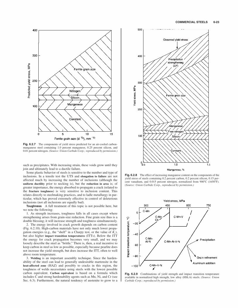
COMMERCIAL STEELS 6-23
such as precipitates. With increasing strain, these voids grow until theyjoin and ultimately lead to a ductile failure.Some plastic behavior of steels is sensitive to the number and type of
inclusions. In a tensile test the UTS and elongation to failure are notaffected much by increasing the number of inclusions (although theuniform ductility prior to necking is), but the reduction in area is; ofgreater importance, the energy absorbed to propagate a crack (related tothe fracture toughness) is very sensitive to inclusion content. Thisrelates directly to steelmaking practices, and to ladle metallurgy in par-ticular, which has proved extremely effective in control of deleteriousinclusions (not all inclusions are equally bad). Toughness A full treatment of this topic is not possible here, but
we note the following:1. As strength increases, toughness falls in all cases except where
strengthening arises from grain-size reduction. Fine grain size thus is adouble blessing; it will increase strength and toughness simultaneously.2. The energy involved in crack growth depends on carbon content
(Fig. 6.2.10). High-carbon materials have not only much lower propa-gation energies (e.g., the “shelf” in a Charpy test, or the value of Kc),but also higher impact transition temperatures (ITTs). Below the ITTthe energy for crack propagation becomes very small, and we mayloosely describe the steel as “brittle.” There is, then, a real incentive tokeep carbon in steel as low as possible, especially because pearlite doesnot increase the yield strength, but does increase the ITT, often to wellabove room temperature.3. Welding is an important assembly technique. Since the harden-
ability of the steel can lead to generally undesirable martensite in theheat-affected zone (HAZ) and possibly to cracks in this region, thetoughness of welds necessitates using steels with the lowest possiblecarbon equivalent. Carbon equivalent is based on a formula whichincludes C and strong hardenability agents such as Mn, Ni, and Cr (seeSec. 6.3). Furthermore, the natural tendency of austenite to grow to a
Fig. 6.2.7 The components of yield stress predicted for an air-cooled carbon-manganese steel containing 1.0 percent manganese, 0.25 percent silicon, and0.01 percent nitrogen. (Source: Union Carbide Corp.; reproduced by permission.)
Fig. 6.2.8 The effect of increasing manganese content on the components of theyield stress of steels containing 0.2 percent carbon, 0.2 percent silicon, 0.15 per-cent vanadium, and 0.015 percent nitrogen, normalized from 9008C (16508F).(Source: Union Carbide Corp., reproduced by permission.)
Fig. 6.2.9 Combinations of yield strength and impact transition temperatureavailable in normalized high strength, low alloy (HSLA) steels. (Source: UnionCarbide Corp.; reproduced by permission.)
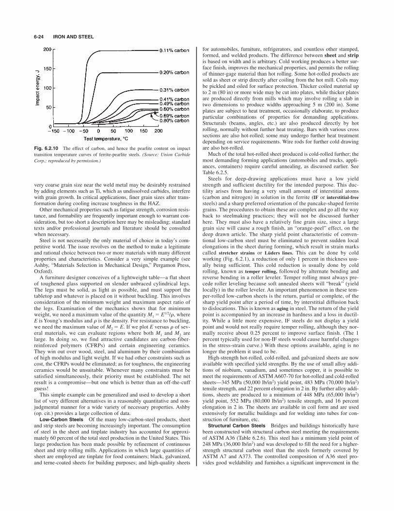
very coarse grain size near the weld metal may be desirably restrainedby adding elements such as Ti, which as undissolved carbides, interferewith grain growth. In critical applications, finer grain sizes after trans-formation during cooling increase toughness in the HAZ.Other mechanical properties such as fatigue strength, corrosion resis-
tance, and formability are frequently important enough to warrant con-sideration, but too short a description here may be misleading; standardtexts and/or professional journals and literature should be consultedwhen necessary.Steel is not necessarily the only material of choice in today’s com-
petitive world. The issue revolves on the method to make a legitimateand rational choice between two or more materials with many differentproperties and characteristics. Consider a very simple example (seeAshby, “Materials Selection in Mechanical Design,” Pergamon Press,Oxford).A furniture designer conceives of a lightweight table—a flat sheet
of toughened glass supported on slender unbraced cylindrical legs.The legs must be solid, as light as possible, and must support thetabletop and whatever is placed on it without buckling. This involvesconsideration of the minimum weight and maximum aspect ratio ofthe legs. Examination of the mechanics shows that for minimumweight, we need a maximum value of the quantity M1 E1/2/r, whereE is Young’s modulus and r is the density. For resistance to buckling,we need the maximum value of M2 E. If we plot E versus r of sev-eral materials, we can evaluate regions where both M1 and M2 arelarge. In doing so, we find attractive candidates are carbon-fiber-reinforced polymers (CFRPs) and certain engineering ceramics.They win out over wood, steel, and aluminum by their combinationof high modulus and light weight. If we had other constraints such ascost, the CFRPs would be eliminated; as for toughness, the engineeringceramics would be unsuitable. Whenever many constraints must besatisfied simultaneously, their priority must be established. The netresult is a compromise—but one which is better than an off-the-cuffguess!This simple example can be generalized and used to develop a short
list of very different alternatives in a reasonably quantitative and non-judgmental manner for a wide variety of necessary properties. Ashby(op. cit.) provides a large collection of data.Low-Carbon Steels Of the many low-carbon-steel products, sheet
and strip steels are becoming increasingly important. The consumptionof steel in the sheet and tinplate industry has accounted for approxi-mately 60 percent of the total steel production in the United States. Thislarge production has been made possible by refinement of continuoussheet and strip rolling mills. Applications in which large quantities ofsheet are employed are tinplate for food containers; black, galvanized,and terne-coated sheets for building purposes; and high-quality sheets
for automobiles, furniture, refrigerators, and countless other stamped,formed, and welded products. The difference between sheet and strip
is based on width and is arbitrary. Cold working produces a better sur-face finish, improves the mechanical properties, and permits the rollingof thinner-gage material than hot rolling. Some hot-rolled products aresold as sheet or strip directly after coiling from the hot mill. Coils maybe pickled and oiled for surface protection. Thicker coiled material upto 2 m (80 in) or more wide may be cut into plates, while thicker platesare produced directly from mills which may involve rolling a slab intwo dimensions to produce widths approaching 5 m (200 in). Someplates are subject to heat treatment, occasionally elaborate, to produceparticular combinations of properties for demanding applications.Structurals (beams, angles, etc.) are also produced directly by hotrolling, normally without further heat treating. Bars with various crosssections are also hot-rolled; some may undergo further heat treatmentdepending on service requirements. Wire rods for further cold drawingare also hot-rolled.Much of the total hot-rolled sheet produced is cold-rolled further; the
most demanding forming applications (automobiles and trucks, appli-ances, containers) require careful annealing, as discussed earlier. SeeTable 6.2.5.Steels for deep-drawing applications must have a low yield
strength and sufficient ductility for the intended purpose. This duc-tility arises from having a very small amount of interstitial atoms(carbon and nitrogen) in solution in the ferrite (IF or interstitial-free
steels) and a sharp preferred orientation of the pancake-shaped ferritegrains. The procedures to obtain these are complex and go all the wayback to steelmaking practices; they will not be discussed furtherhere. They must also have a relatively fine grain size, since a largegrain size will cause a rough finish, an “orange-peel” effect, on thedeep drawn article. The sharp yield point characteristic of conven-tional low-carbon steel must be eliminated to prevent sudden localelongations in the sheet during forming, which result in strain markscalled stretcher strains or Lüders lines. This can be done by coldworking (Fig. 6.2.1), a reduction of only 1 percent in thickness usu-ally being sufficient. This cold reduction is usually done by coldrolling, known as temper rolling, followed by alternate bending andreverse bending in a roller leveler. Temper rolling must always pre-cede roller leveling because soft annealed sheets will “break” (yieldlocally) in the roller leveler. An important phenomenon in these tem-per-rolled low-carbon sheets is the return, partial or complete, of thesharp yield point after a period of time, by interstitial diffusion backto dislocations. This is known as aging in steel. The return of the yieldpoint is accompanied by an increase in hardness and a loss in ductil-ity. While a little more expensive, IF steels do not display a yieldpoint and would not really require temper rolling, although they nor-mally receive about 0.25 percent to improve surface finish. (The 1percent typically used for non-IF steels would cause harmful changesin the stress-strain curve.) With these options available, aging is nolonger the problem it used to be.High-strength hot-rolled, cold-rolled, and galvanized sheets are now
available with specified yield strengths. By the use of small alloy addi-tions of niobium, vanadium, and sometimes copper, it is possible tomeet the requirements of ASTM A607-70 for hot-rolled and cold-rolledsheets—345 MPa (50,000 lb/in2) yield point, 483 MPa (70,000 lb/in2)tensile strength, and 22 percent elongation in 2 in. By further alloy addi-tions, sheets are produced to a minimum of 448 MPa (65,000 lb/in2)yield point, 552 MPa (80,000 lb/in2) tensile strength, and 16 percentelongation in 2 in. The sheets are available in coil form and are usedextensively for metallic buildings and for welding into tubes for con-struction of furniture, etc.Structural Carbon Steels Bridges and buildings historically have
been constructed with structural carbon steel meeting the requirementsof ASTM A36 (Table 6.2.6). This steel has a minimum yield point of248 MPa (36,000 lb/in2) and was developed to fill the need for a higher-strength structural carbon steel than the steels formerly covered byASTM A7 and A373. The controlled composition of A36 steel pro-vides good weldability and furnishes a significant improvement in the
6-24 IRON AND STEEL
Fig. 6.2.10 The effect of carbon, and hence the pearlite content on impact
transition temperature curves of ferrite-pearlite steels. (Source: Union Carbide
Corp.; reproduced by permission.)
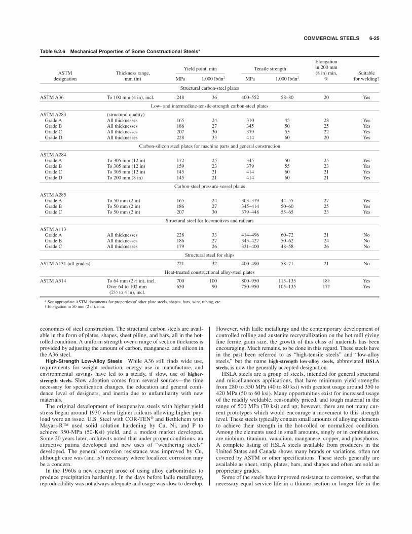
COMMERCIAL STEELS 6-25
economics of steel construction. The structural carbon steels are avail-able in the form of plates, shapes, sheet piling, and bars, all in the hot-rolled condition. A uniform strength over a range of section thickness isprovided by adjusting the amount of carbon, manganese, and silicon inthe A36 steel. High-Strength Low-Alloy Steels While A36 still finds wide use,
requirements for weight reduction, energy use in manufacture, andenvironmental savings have led to a steady, if slow, use of higher-strength steels. Slow adoption comes from several sources—the timenecessary for specification changes, the education and general confi-dence level of designers, and inertia due to unfamiliarity with newmaterials.The original development of inexpensive steels with higher yield
stress began around 1930 when lighter railcars allowing higher pay-load were an issue. U.S. Steel with COR-TEN® and Bethlehem withMayari-R™ used solid solution hardening by Cu, Ni, and P toachieve 350-MPa (50-Ksi) yield, and a modest market developed.Some 20 years later, architects noted that under proper conditions, anattractive patina developed and new uses of “weathering steels”developed. The general corrosion resistance was improved by Cu,although care was (and is!) necessary where localized corrosion maybe a concern.In the 1960s a new concept arose of using alloy carbonitrides to
produce precipitation hardening. In the days before ladle metallurgy,reproducibility was not always adequate and usage was slow to develop.
However, with ladle metallurgy and the contemporary development ofcontrolled rolling and austenite recrystallization on the hot mill givingfine ferrite grain size, the growth of this class of materials has beenencouraging. Much remains, to be done in this regard. These steels havein the past been referred to as “high-tensile steels” and “low-alloysteels,” but the name high-strength low-alloy steels, abbreviated HSLA
steels, is now the generally accepted designation.HSLA steels are a group of steels, intended for general structural
and miscellaneous applications, that have minimum yield strengthsfrom 280 to 550 MPa (40 to 80 ksi) with greatest usage around 350 to420 MPa (50 to 60 ksi). Many opportunities exist for increased usageof the readily weldable, reasonably priced, and tough material in therange of 500 MPa (70 ksi) and up; however, there are not many cur-rent prototypes which would encourage a movement to this strengthlevel. These steels typically contain small amounts of alloying elementsto achieve their strength in the hot-rolled or normalized condition.Among the elements used in small amounts, singly or in combination,are niobium, titanium, vanadium, manganese, copper, and phosphorus.A complete listing of HSLA steels available from producers in theUnited States and Canada shows many brands or variations, often notcovered by ASTM or other specifications. These steels generally areavailable as sheet, strip, plates, bars, and shapes and often are sold asproprietary grades.Some of the steels have improved resistance to corrosion, so that the
necessary equal service life in a thinner section or longer life in the
Table 6.2.6 Mechanical Properties of Some Constructional Steels*
Elongation
Yield point, min Tensile strength in 200 mmASTM Thickness range, (8 in) min, Suitable
designation mm (in) MPa 1,000 lb/in2 MPa 1,000 lb/in2 % for welding?
Structural carbon-steel plates
ASTM A36 To 100 mm (4 in), incl. 248 36 400–552 58–80 20 Yes
Low- and intermediate-tensile-strength carbon-steel plates
ASTM A283 (structural quality)Grade A All thicknesses 165 24 310 45 28 YesGrade B All thicknesses 186 27 345 50 25 YesGrade C All thicknesses 207 30 379 55 22 YesGrade D All thicknesses 228 33 414 60 20 Yes
Carbon-silicon steel plates for machine parts and general construction
ASTM A284Grade A To 305 mm (12 in) 172 25 345 50 25 YesGrade B To 305 mm (12 in) 159 23 379 55 23 YesGrade C To 305 mm (12 in) 145 21 414 60 21 YesGrade D To 200 mm (8 in) 145 21 414 60 21 Yes
Carbon-steel pressure-vessel plates
ASTM A285Grade A To 50 mm (2 in) 165 24 303–379 44–55 27 YesGrade B To 50 mm (2 in) 186 27 345–414 50–60 25 YesGrade C To 50 mm (2 in) 207 30 379–448 55–65 23 Yes
Structural steel for locomotives and railcars
ASTM A113Grade A All thicknesses 228 33 414–496 60–72 21 NoGrade B All thicknesses 186 27 345–427 50–62 24 NoGrade C All thicknesses 179 26 331–400 48–58 26 No
Structural steel for ships
ASTM A131 (all grades) 221 32 400–490 58–71 21 No
Heat-treated constructional alloy-steel plates
ASTM A514 To 64 mm (2 in), incl. 700 100 800–950 115–135 18† YesOver 64 to 102 mm 650 90 750–950 105–135 17† Yes(2 to 4 in), incl.
* See appropriate ASTM documents for properties of other plate steels, shapes, bars, wire, tubing, etc.† Elongation in 50 mm (2 in), min.
1⁄2
1⁄2
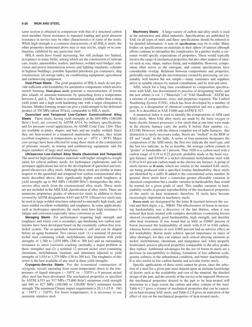
same section is obtained in comparison with that of a structural carbonsteel member. Good resistance to repeated loading and good abrasionresistance in service may be other characteristics of some of the steels.While high strength is a common characteristic of all HSLA steels, theother properties mentioned above may or may not be, singly or in com-bination, exhibited by any particular steel.HSLA steels have found increasing, but still perhaps too limited,
acceptance in many fields, among which are the construction of railroadcars, trucks, automobiles, trailers, and buses; welded steel bridges; tele-vision and power-transmission towers and lighting standards; columnsin highrise buildings; portable liquefied petroleum gas containers; shipconstruction; oil storage tanks; air conditioning equipment; agriculturaland earthmoving equipment.Dual-Phase Steels The good properties of HSLA steels do not pro-
vide sufficient cold formability for automotive components which involvestretch forming. Dual-phase steels generate a microstructure of ferriteplus islands of austenite-martensite by quenching from a temperaturebetween A1 and A3. This leads to continuous yielding (rather than a sharpyield point) and a high work-hardening rate with a larger elongation tofracture. Modest forming strains can give a yield strength in the deformedproduct of 350 MPa (about 50 ksi), comparable to HSLA steels.Quenched and Tempered Low-Carbon Constructional Alloy
Steels These steels, having yield strengths at the 689-MPa (100,000lb/in2) level, are covered by ASTM A514, by military specifications,and for pressure-vessel applications, by ASME Code Case 1204. Theyare available in plates, shapes, and bars and are readily welded. Sincethey are heat-treated to a tempered martensitic structure, they retainexcellent toughness at temperatures as low as %458C (%508F). Majorcost savings have been effected by using these steels in the constructionof pressure vessels, in mining and earthmoving equipment, and formajor members of large steel structures. Ultraservice Low-Carbon Alloy Steels (Quenched and Tempered)
The need for high-performance materials with higher strength-to-weightratios for critical military needs, for hydrospace explorations, and foraerospace applications has led to the development of quenched and tem-pered ultraservice alloy steels. Although these steels are similar in manyrespects to the quenched and tempered low-carbon constructional alloysteels described above, their significantly higher notch toughness atyield strengths up to 965 MPa (140,000 lb/in2) distinguishes the ultra-service alloy steels from the constructional alloy steels. These steelsare not included in the AISI-SAE classification of alloy steels. There arenumerous proprietary grades of ultraservice steels in addition to thosecovered by ASTM designations A543 and A579. Ultraservice steels maybe used in large welded structures subjected to unusually high loads, andmust exhibit excellent weldability and toughness. In some applications,such as hydrospace operations, the steels must have high resistance tofatigue and corrosion (especially stress corrosion) as well.Maraging Steels For performance requiring high strength and
toughness and where cost is secondary, age-hardening low-carbon mar-tensites have been developed based on the essentially carbon-free iron-nickel system. The as-quenched martensite is soft and can be shapedbefore an aging treatment. Two classes exist: (1) a nominal 18 percentnickel steel containing cobalt, molybdenum, and titanium with yieldstrengths of 1,380 to 2,070 MPa (200 to 300 ksi) and an outstandingresistance to stress corrosion cracking (normally a major problem atthese strengths) and (2) a nominal 12 percent nickel steel containingchromium, molybdenum, titanium, and aluminum adjusted to yieldstrengths of 1,034 to 1,379 MPa (150 to 200 ksi). The toughness of thisseries is the best available of any steel at these yield strengths. Cryogenic-Service Steels For the economical construction of
cryogenic vessels operating from room temperature down to the tem-perature of liquid nitrogen (%1958C or %3208F) a 9 percent nickelalloy steel has been developed. The mechanical properties as specifiedby ASTM A353 are 517 MPa (75,000 lb/in2) minimum yield strengthand 689 to 827 MPa (100,000 to 120,000 lb/in2) minimum tensilestrength. The minimum Charpy impact requirement is 20.3 J (15 ft " 1bf)at %1958C (%3208F). For lower temperatures, it is necessary to useaustenitic stainless steel.
Machinery Steels A large variety of carbon and alloy steels is usedin the automotive and allied industries. Specifications are published bySAE on all types of steel, and these specifications should be referred tofor detailed information. A note on specifications may be in order. Manybodies set specifications on materials in their sphere of interest althoughefforts continue to rationalize the complexities. In a perfect world, a cus-tomer would specify expectations of properties. These would typicallyinvolve the range of mechanical properties, but also other matters of inter-est such as size, shape, surface finish, and weldability. However, compo-sition often serves as the surrogate, and current specifications haveconsiderable overlap. Relations between compositions and properties,preferably seen through the microstructure created by processing, are rea-sonably well known but not simple—-many customers and suppliersarrive at suitable choices by mutual consultation, and by trial and error.AISI, which for a long time coordinated its composition specifica-
tions with SAE, has discontinued its practice of designating steels, andthe new arbiter is vol. 1 (“Materials”) of “SAE Handbook.” ASTM hasa mixture of compositions, sizes, and properties required. The UnifiedNumbering System (UNS), which has been developed by a number ofgroups, is a designation of chemical composition and not a specifica-tion. It is described in SAE J1086 and ASTM E 527.A numerical index is used to identify the compositions of AISI (and
SAE) steels. Most SAE alloy steels are made by the basic oxygen orbasic electric furnace processes; a few steels that at one time were madein the electric furnace carry the prefix E before their number, i.e.,E52100. However, with the almost complete use of ladle furnaces, thisdistinction is rarely necessary today. Steels are “melted” in the BOP orEF and “made” in the ladle. A series of four numerals designates thecomposition of the AISI steels; the first two indicate the steel type, andthe last two indicate, as far as feasible, the average carbon content in“points” or hundredths of 1 percent. Thus 1020 is a carbon steel with acarbon range of 0.18 to 0.23 percent, probably made in the basic oxy-gen furnace, and E4340 is a nickel-chromium molybdenum steel with0.38 to 0.43 percent carbon made in the electric-arc furnace. A group ofsteels known as H steels, which are similar to the standard SAE steels,are being produced with a specified Jominy hardenability; these steelsare identified by a suffix H added to the conventional series number. Ingeneral, these steels have a somewhat greater allowable variation inchemical composition but a smaller variation in hardenability than wouldbe normal for a given grade of steel. This smaller variation in hard-enability results in greater reproducibility of the mechanical propertiesof the steels on heat treatment; therefore, H steels have becomeincreasingly important in machinery steels.
Boron steels are designated by the letter B inserted between the sec-ond and third digits, e.g., 50B44. The effectiveness of boron in increas-ing hardenability was a discovery of the late thirties, when it wasnoticed that heats treated with complex deoxidizers (containing boron)showed exceptionally good hardenability, high strength, and ductilityafter heat treatment. It was found that as little as 0.0005 percent ofboron increased the hardenability of steels with 0.15 to 0.60 carbon,whereas boron contents of over 0.005 percent had an adverse effect onhot workability. Boron steels achieve special importance in times ofalloy shortages, for they can replace such critical alloying elements asnickel, molybdenum, chromium, and manganese and, when properlyheattreated, possess physical properties comparable to the alloy gradesthey replace. Additional advantages for the use of boron in steels are adecrease in susceptibility to flaking, formation of less adherent scale,greater softness in the unhardened condition, and better machinability.It is also useful in low-carbon bainite and acicular ferrite steels.Specific applications of these steels cannot be given, since the selec-
tion of a steel for a given part must depend upon an intimate knowledgeof factors such as the availability and cost of the material, the detaileddesign of the part, and the severity of the service to be imposed. However,the mechanical properties desired in the part to be heat-treated willdetermine to a large extent the carbon and alloy content of the steel.Table 6.2.7 gives a résumé of mechanical properties that can be expect-ed on heat-treating SAE steels, and Table 6.2.8 gives an indication of theeffect of size on the mechanical properties of heat-treated steels.
6-26 IRON AND STEEL

COMMERCIAL STEELS 6-27
The low-carbon SAE steels are used for carburized parts, cold-headedbolts and rivets, and for similar applications where high quality isrequired. The SAE 1100 series are low-carbon free-cutting steels forhigh-speed screw-machine stock and other machining purposes. Thesesteels have high sulfur present in the steel in the form of manganese sul-fide inclusions causing the chips to break short on machining.Manganese and phosphorus harden and embrittle the steel, which alsocontributes toward free machining. The high manganese contents are
intended to ensure that all the sulfur is present as manganese sulfide.Lead was a common additive, but there are environmental problems;experiments have been conducted with selenium, tellurium, tin, and bis-muth as replacements.
Cold-finished carbon-steel bars are used for bolts, nuts, typewriterand cash register parts, motor and transmission power shafting, pistonpins, bushings, oil-pump shafts and gears, etc. Representative mechan-ical properties of cold-drawn steel are given in Table 6.2.9. Besides
Table 6.2.7 Mechanical Properties of Certain SAE Steels with Various Heat TreatmentsSections up to 40 mm (or 1 diam or thickness)
Tempering temp Tensile strength Yield pointElongation
1,000 1,000 Reduction in 50 mm Brinell8C 8F MPa lb/in2 MPa lb/in2 of area, % (2 in), % hardness
SAE 1040 quenched in water from 8158C (1,5008F)
315 600 862 125 717 104 46 11 260425 800 821 119 627 91 53 13 250540 1,000 758 110 538 78 58 15 220595 1,100 745 108 490 71 60 17 216650 1,200 717 104 455 66 62 20 210705 1,300 676 98 414 60 64 22 205
SAE 1340 normalized at 8658C (1,5858F), quenched in oil from 8458C (1,5508F)
315 600 1,565 227 1,420 206 43 11 448425 800 1,248 181 1,145 166 51 13 372540 1,000 966 140 834 121 58 17.5 297595 1,100 862 125 710 103 62 20 270650 1,200 793 115 607 88 65 23 250705 1,300 758 110 538 78 68 25.5 234
SAE 4042 normalized at 8708C (1,6008F), quenched in oil from 8158C (1,5008F)
315 600 1,593 231 1,448 210 41 12 448425 800 1,207 175 1,089 158 50 14 372540 1,000 966 140 862 125 58 19 297595 1,100 862 125 758 110 62 23 260650 1,200 779 113 683 99 65 26 234705 1,800 724 105 634 92 68 30 210
1⁄2
Table 6.2.8 Effect of Size of Specimen on the Mechanical Properties of Some SAE Steels
Diam of Tensile strength Yield pointElongation
section1,000 1,000 Reduction in 50 mm Brinell
in mm MPa lb/in2 MPa lb/in2 of area, % (2 in), % hardness
SAE 1040, water-quenched, tempered at 5408C (1,0008F)
1 25 758 110 538 78 58 15 2302 50 676 98 448 65 49 20 1943 75 641 93 407 59 48 23 1854 100 621 90 393 57 47 24.5 1805 125 614 89 372 54 46 25 180
SAE 4140, oil-quenched, tempered at 5408C (1,0008F)
1 25 1,000 145 883 128 56 18 2972 50 986 143 802 125 58 19 2973 75 945 137 814 118 59 20 2834 100 869 126 758 110 60 18 2705 125 841 122 724 105 59 17 260
SAE 8640, oil-quenched, tempered at 5408C (1,0008F)
1 25 1,158 168 1,000 145 44 16 3322 50 1,055 153 910 132 45 20 3133 75 951 138 807 117 46 22 2834 100 889 129 745 108 46 23 2705 125 869 126 724 105 45 23 260
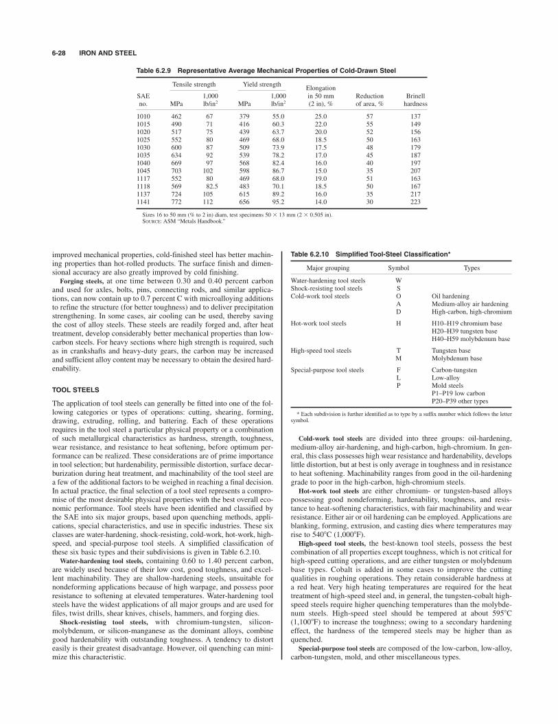
improved mechanical properties, cold-finished steel has better machin-ing properties than hot-rolled products. The surface finish and dimen-sional accuracy are also greatly improved by cold finishing.
Forging steels, at one time between 0.30 and 0.40 percent carbonand used for axles, bolts, pins, connecting rods, and similar applica-tions, can now contain up to 0.7 percent C with microalloying additionsto refine the structure (for better toughness) and to deliver precipitationstrengthening. In some cases, air cooling can be used, thereby savingthe cost of alloy steels. These steels are readily forged and, after heattreatment, develop considerably better mechanical properties than low-carbon steels. For heavy sections where high strength is required, suchas in crankshafts and heavy-duty gears, the carbon may be increasedand sufficient alloy content may be necessary to obtain the desired hard-enability.
TOOL STEELS
The application of tool steels can generally be fitted into one of the fol-lowing categories or types of operations: cutting, shearing, forming,drawing, extruding, rolling, and battering. Each of these operationsrequires in the tool steel a particular physical property or a combinationof such metallurgical characteristics as hardness, strength, toughness,wear resistance, and resistance to heat softening, before optimum per-formance can be realized. These considerations are of prime importancein tool selection; but hardenability, permissible distortion, surface decar-burization during heat treatment, and machinability of the tool steel area few of the additional factors to be weighed in reaching a final decision.In actual practice, the final selection of a tool steel represents a compro-mise of the most desirable physical properties with the best overall eco-nomic performance. Tool steels have been identified and classified bythe SAE into six major groups, based upon quenching methods, appli-cations, special characteristics, and use in specific industries. These sixclasses are water-hardening, shock-resisting, cold-work, hot-work, high-speed, and special-purpose tool steels. A simplified classification ofthese six basic types and their subdivisions is given in Table 6.2.10.
Water-hardening tool steels, containing 0.60 to 1.40 percent carbon,are widely used because of their low cost, good toughness, and excel-lent machinability. They are shallow-hardening steels, unsuitable fornondeforming applications because of high warpage, and possess poorresistance to softening at elevated temperatures. Water-hardening toolsteels have the widest applications of all major groups and are used forfiles, twist drills, shear knives, chisels, hammers, and forging dies.
Shock-resisting tool steels, with chromium-tungsten, silicon-molybdenum, or silicon-manganese as the dominant alloys, combinegood hardenability with outstanding toughness. A tendency to distorteasily is their greatest disadvantage. However, oil quenching can mini-mize this characteristic.
Cold-work tool steels are divided into three groups: oil-hardening,medium-alloy air-hardening, and high-carbon, high-chromium. In gen-eral, this class possesses high wear resistance and hardenability, developslittle distortion, but at best is only average in toughness and in resistanceto heat softening. Machinability ranges from good in the oil-hardeninggrade to poor in the high-carbon, high-chromium steels.
Hot-work tool steels are either chromium- or tungsten-based alloyspossessing good nondeforming, hardenability, toughness, and resis-tance to heat-softening characteristics, with fair machinability and wearresistance. Either air or oil hardening can be employed. Applications areblanking, forming, extrusion, and casting dies where temperatures mayrise to 5408C (1,0008F).
High-speed tool steels, the best-known tool steels, possess the bestcombination of all properties except toughness, which is not critical forhigh-speed cutting operations, and are either tungsten or molybdenumbase types. Cobalt is added in some cases to improve the cuttingqualities in roughing operations. They retain considerable hardness ata red heat. Very high heating temperatures are required for the heattreatment of high-speed steel and, in general, the tungsten-cobalt high-speed steels require higher quenching temperatures than the molybde-num steels. High-speed steel should be tempered at about 5958C(1,1008F) to increase the toughness; owing to a secondary hardeningeffect, the hardness of the tempered steels may be higher than asquenched.
Special-purpose tool steels are composed of the low-carbon, low-alloy,carbon-tungsten, mold, and other miscellaneous types.
6-28 IRON AND STEEL
Table 6.2.9 Representative Average Mechanical Properties of Cold-Drawn Steel
Tensile strength Yield strengthElongation
SAE 1,000 1,000 in 50 mm Reduction Brinellno. MPa lb/in2 MPa lb/in2 (2 in), % of area, % hardness
1010 462 67 379 55.0 25.0 57 1371015 490 71 416 60.3 22.0 55 1491020 517 75 439 63.7 20.0 52 1561025 552 80 469 68.0 18.5 50 1631030 600 87 509 73.9 17.5 48 1791035 634 92 539 78.2 17.0 45 1871040 669 97 568 82.4 16.0 40 1971045 703 102 598 86.7 15.0 35 2071117 552 80 469 68.0 19.0 51 1631118 569 82.5 483 70.1 18.5 50 1671137 724 105 615 89.2 16.0 35 2171141 772 112 656 95.2 14.0 30 223
Sizes 16 to 50 mm (% to 2 in) diam, test specimens 50 # 13 mm (2 # 0.505 in).SOURCE: ASM “Metals Handbook.”
Table 6.2.10 Simplified Tool-Steel Classification*
Major grouping Symbol Types
Water-hardening tool steels WShock-resisting tool steels SCold-work tool steels O Oil hardening
A Medium-alloy air hardeningD High-carbon, high-chromium
Hot-work tool steels H H10–H19 chromium baseH20–H39 tungsten baseH40–H59 molybdenum base
High-speed tool steels T Tungsten baseM Molybdenum base
Special-purpose tool steels F Carbon-tungstenL Low-alloyP Mold steels
P1–P19 low carbonP20–P39 other types
* Each subdivision is further identified as to type by a suffix number which follows the lettersymbol.

STAINLESS STEELS 6-29
SPRING STEEL
For small springs, steel is often supplied to spring manufacturers in aform that requires no heat treatment except perhaps a low-temperatureanneal to relieve forming strains. Types of previously treated steel wirefor small helical springs are music wire which has been given a specialheat treatment called patenting and then cold-drawn to develop a highyield strength, hard-drawn wire which is of lower quality than musicwire since it is usually made of lower-grade material and is seldompatented, and oil-tempered wire which has been quenched and tem-pered. The wire usually has a Brinell hardness between 352 and 415,although this will depend on the application of the spring and the sever-ity of the forming operation. Steel for small flat springs has either beencold-rolled or quenched and tempered to a similar hardness.Steel for both helical and flat springs which is hardened and tempered
after forming is usually supplied in an annealed condition. Plain carbonsteel is satisfactory for small springs; for large springs it is necessary touse alloy steels such as chrome-vanadium or silicon-manganese steel inorder to obtain a uniform structure throughout the cross section. It isespecially important for springs that the surface of the steel be free fromall defects and decarburization, which lowers fatigue strength.
SPECIAL ALLOY STEELS
Many steel alloys with compositions tailored to specific requirementsare reported periodically. Usually, the compositions and/or treatmentsare patented, and they are most likely to have registered trademarks andtrade names. They are too numerous to be dealt with here in any greatdetail, but a few of the useful properties exhibited by some of those spe-cial alloys are mentioned.Iron-silicon alloys with minimum amounts of both carbon and other
alloying elements have been used by the electrical equipment industryfor a long time; often these alloys are known as electrical sheet steel.Iron-nickel alloys with high proportions of nickel, and often with otheralloying elements, elicit properties such as nonmagnetic behavior, highpermeability, low hysteresis loss, low coefficient of expansion, etc.;iron-cobalt alloys combined with other alloying elements can result inmaterials with low resistivity and high hysteresis loss. The reader inter-ested in the use of materials with some of these or other desired prop-erties is directed to the extensive literature and data available.
STAINLESS STEELS
by James D. Redmond
REFERENCES: “Design Guidelines for the Selection and Use of Stainless Steel,”Specialty Steel Institute of North America (SSINA), Washington, DC. Publicationsof the Nickel Development Institute, Toronto, Ontario, Canada. “MetalsHandbook,” 10th ed., ASM International. ASTM Standards.
When the chromium content is increased to about 11 percent in an iron-chromium alloy, the resulting material is generally classified as a stain-less steel. With that minimum quantity of chromium, a thin, protective,passive film forms spontaneously on the steel. This passive film acts asa barrier to prevent corrosion. Further increases in chromium contentstrengthen the passive film and enable it to repair itself if it is damagedin a corrosive environment. Stainless steels are also heat-resistantbecause exposure to high temperatures (red heat and above) causes theformation of a tough oxide layer which retards further oxidation.Other alloying elements are added to stainless steels to improve
corrosion resistance in specific environments or to modify or optimizemechanical properties or characteristics. Nickel changes the crystalstructure to improve ductility, toughness, and weldability. Nickel improvescorrosion resistance in reducing environments such as sulfuric acid.Molybdenum increases pitting and crevice corrosion resistance in chlo-ride environments. Carbon and nitrogen increase strength. Aluminumand silicon improve oxidation resistance. Sulfur and selenium are addedto improve machinability. Titanium and niobium (columbium) areadded to prevent sensitization by preferentially combining with carbonand nitrogen, thereby preventing intergranular corrosion.
Stainless Steel Grades There are more than 200 different gradesof stainless steel. Each is alloyed to provide a combination of corrosionresistance, heat resistance, mechanical properties, or other specificcharacteristics. There are five families of stainless steels: austenitic, fer-ritic, duplex, martensitic, and precipitation hardening. Table 6.2.11 is arepresentative list of stainless steel grades by family and chemical com-position as typically specified in ASTM Standards. The mechanicalproperties of many of these grades are summarized in Table 6.2.12.Note that the number designation of a stainless steel does not describeits performance when utilized to resist corrosion.
Austenitic stainless steels are the most widely used, and while mostare designated in the 300 series, some of the highly alloyed grades,though austenitic, have other identifying grade designations, e.g., alloy20, 904L, and the 6 percent molybdenum grades. These latter are oftenknown by their proprietary designation. These stainless steel grades areavailable in virtually all wrought product forms, and many areemployed as castings. Some austenitic grades in which manganese andnitrogen are substituted partially for nickel are also designated in the200 series. Types 304 (18 Cr, 8 Ni) and 316 (17 Cr, 10 Ni, 2 Mo) arethe workhorse grades, and they are utilized for a broad range of equip-ment and structures. Austenitic grades can be hardened by cold workbut not by heat treatment; cold work increases strength with an accom-panying decrease in ductility. They provide excellent corrosion resis-tance, respond very well to forming operations, and are readily welded.When fully annealed, they are not magnetic, but may become slightlymagnetic when cold-worked. Compared to carbon steel, they have highercoefficients of thermal expansion and lower thermal conductivities.When austenitic grades are employed to resist corrosion, their perfor-mance may vary over a wide range, depending on the particular corro-sive media encountered. As a general rule, increased levels ofchromium, molybdenum, and nitrogen result in increased resistance topitting and crevice corrosion in chloride environments. Type 304 is rou-tinely used for atmospheric corrosion resistance and to handle lowchlo-ride potable water. At the other end of the spectrum are the 6% Moaustenitic stainless steels, which have accumulated many years of ser-vice experience handling seawater in utility steam condensers and inpiping systems on offshore oil and gas platforms. Highly alloyedaustenitic stainless steels are subject to precipitation reactions in therange of 1,500 to 1,8008F (815 to 9808C), resulting in a reduction oftheir corrosion resistance and ambient-temperature impact toughness.Low-carbon grades, or L grades, are restricted to very low levels of
carbon (usually 0.030 wt % maximum) to reduce the possibility of sen-sitization due to chromium carbide formation either during welding orwhen exposed to a high-temperature thermal cycle. When a sensitizedstainless steel is exposed subsequently to a corrosive environment,intergranular corrosion may occur. Other than improved resistance tointergranular corrosion, the low-carbon grades have the same resistanceto pitting, crevice corrosion, and chloride stress corrosion cracking as thecorresponding grade with the higher level of carbon (usually 0.080 wt %maximum).There is a trend to dual-certify some pairs of stainless-steel grades.
For example, an 18 Cr–8 Ni stainless steel low enough in carbon tomeet the requirements of an L grade and high enough in strength toqualify as the standard carbon version may be dual-certified. ASTMspecifications allow such a material to be certified and marked, forexample, 304/304L and S30400/S30403.
Ferritic stainless steels are iron-chromium alloys with 11 to 30 percentchromium. They can be strengthened slightly by cold working. They aremagnetic. They are difficult to produce in plate thicknesses, but arereadily available in sheet and bar form. Some contain molybdenum forimproved corrosion resistance in chloride environments. They exhibitexcellent resistance to chloride stress corrosion cracking. Resistance topitting and crevice corrosion is a function of the total chromium andmolybdenum content. The coefficient of thermal expansion is similar tothat of carbon steel. The largest quantity produced is Type 409 (11 Cr),used extensively for automobile catalytic converters, mufflers, andexhaust system components. The most highly alloyed ferritic stainlesssteels have a long service history in seawater-cooled utility condensers.

6-30
Table 6.2.11
ASTM/AWS/AMS Chemical Composition (Wt.Pct)a
UNS
number
Grade
CCr
NI
Mo
Cu
NOther
Austenitic stainless steels
S20100
201
0.15
16.00–18.00
3.50–5.50
—b
—0.25
Mn: 5.50–7.50
S20200
202
0.15
17.00–19.00
4.00–6.00
——
0.25
Mn: 7.50–10.00
S30100
301
0.15
16.00–18.00
6.00–8.00
——
0.50
—S30200
302
0.15
17.00–19.00
8.00–10.00
——
0.10
—S30300
303
0.15
17.00–19.00
8.00–10.00
——
—S: 0.15 min
S30323
303Se
0.15
17.00–19.00
8.00–10.00
——
—Se: 0.15 min
S30400
304
0.08
18.00–20.00
8.00–10.50
——
0.10
—S30403
304L
0.030
18.00–20.00
8.00–12.00
——
0.10
—S30409
304H
0.04–0.10
18.00–20.00
8.00–10.50
——
——
S30451
304N
0.08
18.00–20.00
8.00–10.50
——
0.10–0.16
—S30500
305
0.12
17.00–19.00
10.50–13.00
——
——
S30800
308
0.08
19.00–21.00
10.00–12.00
——
——
S30883
308L
0.03
19.50–22.00
9.00–11.00
0.05
0.75
Si: 0.39–0.65
S30908
309S
0.08
22.00–24.00
12.00–15.00
——
——
S31008
310S
0.08
24.00–26.00
19.00–22.00
——
——
S31600
316
0.08
16.00–18.00
10.00–14.00
2.00–3.00
—0.10
—S31603
316L
0.030
16.00–18.00
10.00–14.00
2.00–3.00
—0.10
—S31609
316H
0.04–0.10
16.00–18.00
10.00–14.00
2.00–3.00
—0.10
—S31703
317L
0.030
18.00–20.00
11.00–15.00
3.00–4.00
—0.10
—S31726
317LMN
0.030
17.00–20.00
13.50–17.50
4.0–5.0
—0.10–0.20
—S32100
321
0.080
17.00–19.00
9.00–12.00
——
0.10
Ti: 5(C $
N) min; 0.70 max
S34700
347
0.080
17.00–19.00
9.00–13.00
——
—Nb: 10C min; 1.00 max
N08020
Alloy 20
0.07
19.00–21.00
32.00–38.00
2.00–3.00
3.00–4.00
—Nb $
Ta: 8C min; 1.00 max
N08904
904L
0.020
19.00–23.00
23.00–28.00
4.0–5.0
1.0–2.0
0.10
—S31254
254 SMQc
0.020
19.50–20.50
17.50–18.50
6.00–6.50
0.50–1.00
0.18–0.22
—N08367
AL-6XNd
0.030
20.00–22.00
23.50–25.50
6.00–7.00
0.75
0.18–0.25
—N08926
25-6MOe /1925hMof
0.020
19.00–21.00
24.00–26.00
6.0–7.0
0.5–1.0
0.15–0.25
—S32654
654 SMOc
0.020
24.00–25.00
21.00–23.00
7.00–8.00
0.30–0.60
0.45–0.55
Mn: 2.00–4.00
Duplex stainless steels
S31260
DP-3g
0.030
24.0–26.0
5.50–7.50
2.50–3.50
0.20–0.80
0.10–0.30
W 0.10–0.50
S31803
—0.030
21.0–23.0
4.50–6.50
2.50–3.50
—0.08–0.20
—S32003
AL-2003d
0.030
19.5–22.5
3.0–4.0
1.50–2.00
—0.14–0.20
—S32101
LDX 2101c
0.040
21.0–22.0
1.35–1.70
0.10–0.80
—0.20–0.25
—S32205
2205
0.030
21.0–23.0
4.50–6.50
2.50–3.50
—0.14–0.20
—S32304
2304
0.030
21.5–24.5
3.00–5.00
0.05–0.60
0.05–0.50
0.05–0.20
—S32550
Ferralium 255h
0.040
24.0–27.0
4.50–6.50
2.90–3.90
1.5–2.5
0.10–0.25
—S32750
2507
0.030
24.0–26.0
6.00–8.00
3.00–5.00
0.50
0.24–0.32
—S32900
329
0.08
23.00–28.00
2.50–5.00
1.00–2.00
——
—
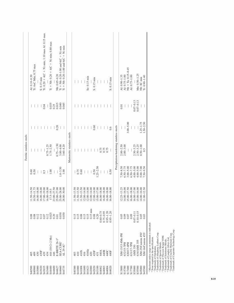
6-31
Ferritic stainless steels
S40500
405
0.08
11.50–14.50
0.60
——
—Al: 0.10–0.30
S40900
409
0.08
10.50–11.75
0.50
——
—Ti: 6xC Min; 0.75 max
S43000
430
0.12
16.00–18.00
——
——
—S43020
430F
0.12
16.00–18.00
——
——
S: 0.15 min
S43035
439
0.07
17.00–19.00
0.5
——
0.04
Ti: 0.20 $
4(C$N) min; 1.10 max Al: 0.15 max
S43400
434
0.12
16.00–18.00
—0.75–1.25
——
—S44400
444 (18 Cr-2 Mo)
0.025
17.5–19.5
1.00
1.75–2.50
—0.035
Ti $Nb: 0.20 $
4(C$N) min; 0.80 max
S44600
446
0.20
23.00–27.50
——
—0.25
—S44627
E-BRITE 26-1d
0.01
25.00–27.00
—0.75—1.50
0.20
0.015
Nb: 0.05–0.20
S44660
SEA-CUREi
0.030
25.00–28.00
1.0–3.50
3.00–4.00
—0.040
Ti $Nb: 0.20-1.00 and 6(C $
N) min
S44735
AL 29-4Cc
0.030
28.00–30.00
1.00
3.60–4.20
—0.045
Ti $Nb: 0.20–1.00 and 6(C $
N) min
Martensitic stainless steels
S40300
403
0.15
11.50–13.50
——
——
—S41000
410
0.15
11.50–13.50
0.75
——
——
S41008
410S
0.08
11.50–13.50
0.60
——
——
S41600
416
0.15
12.00–14.00
——
——
—S41623
416Se
0.15
12.00–14.00
——
——
Se: 0.15 min
S42000
420
0.15 min
12.00–14.00
——
——
—S42020
420F
0.08
12.00–14.00
0.50
—0.60
—S: 0.15 min
S43100
431
0.20
15.00–17.00
1.25–2.50
——
——
S44002
440A
0.60–0.75
16.00–18.00
—0.75
——
—S44003
440B
0.75–0.95
16.00–18.00
—0.75
——
—S44004
440C
0.95–1.20
16.00–18.00
—0.75
——
—S44020
440F
0.95–1.20
16.00–18.00
0.50
—0.6
—S: 0.15 min
Precipitation-hardening stainless steels
S13800
XM-13/13-8Mo PH
0.05
12.25–13.25
7.50–8.50
2.00–2.50
—0.01
Al: 0.90–1.35
S15700
632/15-7PH
0.09
14.00–16.00
6.50–7.75
2.00–3.00
——
Al: 0.75–1.00
S17400
630/17-4PH
0.07
15.00–17.50
3.00–5.00
—3.00–5.00
—Nb $
Ta: 0.15–0.45
S17700
631/17-7PH
0.09
16.00–18.00
6.50–7.75
——
—Al: 0.75–1.00
S35000
AMS 350
0.07–0.11
16.00–17.00
4.00–5.00
2.50–3.25
—0.07–0.13
—S35500
634/AMS 355
0.10–0.15
15.00–16.00
4.00–5.00
2.50–3.25
—0.07–0.13
Mn: 0.50–1.25
S45000
XM-25/Custom 450j
0.05
14.00–16.00
5.00–7.00
0.50–1.00
1.25–1.75
—Nb: 8C min
S45500
XM-16/Custom 455j
0.03
11.00–12.50
7.50–9.50
0.5
1.50–2.50
—Ti: 0.90–1.40
aMaximum unless range or minimum is indicated.
bNone required in the specification.
cTrademark of Outokumu.
dTrademark of Allegheny Ludlum Corp.
eTrademark of Special Metals.
fTrademark of Thyssen Krupp VDM.
gTrademark of Sumitomo Metals.
hTrademark of Langley Alloys Ltd.
iTrademark of Crucible Materials Corp.
jTrademark of Carpenter Technology Corp.
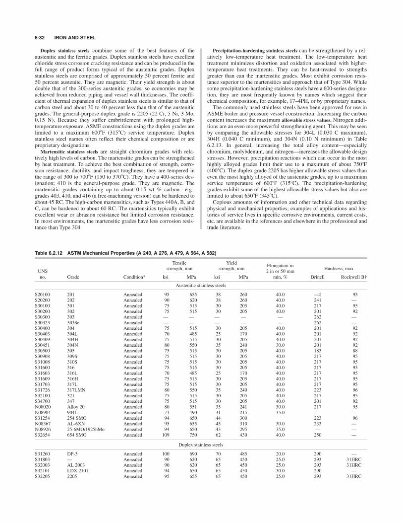
Duplex stainless steels combine some of the best features of theaustenitic and the ferritic grades. Duplex stainless steels have excellentchloride stress corrosion cracking resistance and can be produced in thefull range of product forms typical of the austenitic grades. Duplexstainless steels are comprised of approximately 50 percent ferrite and50 percent austenite. They are magnetic. Their yield strength is aboutdouble that of the 300-series austenitic grades, so economies may beachieved from reduced piping and vessel wall thicknesses. The coeffi-cient of thermal expansion of duplex stainless steels is similar to that ofcarbon steel and about 30 to 40 percent less than that of the austeniticgrades. The general-purpose duplex grade is 2205 (22 Cr, 5 Ni, 3 Mo,0.15 N). Because they suffer embrittlement with prolonged high-temperature exposure, ASME constructions using the duplex grades arelimited to a maximum 6008F (3158C) service temperature. Duplexstainless steel names often reflect their chemical composition or areproprietary designations.
Martensitic stainless steels are straight chromium grades with rela-tively high levels of carbon. The martensitic grades can be strengthenedby heat treatment. To achieve the best combination of strength, corro-sion resistance, ductility, and impact toughness, they are tempered inthe range of 300 to 7008F (150 to 3708C). They have a 400-series des-ignation; 410 is the general-purpose grade. They are magnetic. Themartensitic grades containing up to about 0.15 wt % carbon—e.g.,grades 403, 410, and 416 (a free-machining version) can be hardened toabout 45 RC. The high-carbon martensitics, such as Types 440A, B, andC, can be hardened to about 60 RC. The martensitics typically exhibitexcellent wear or abrasion resistance but limited corrosion resistance.In most environments, the martensitic grades have less corrosion resis-tance than Type 304.
Precipitation-hardening stainless steels can be strengthened by a rel-atively low-temperature heat treatment. The low-temperature heattreatment minimizes distortion and oxidation associated with higher-temperature heat treatments. They can be heat-treated to strengthsgreater than can the martensitic grades. Most exhibit corrosion resis-tance superior to the martensitics and approach that of Type 304. Whilesome precipitation-hardening stainless steels have a 600-series designa-tion, they are most frequently known by names which suggest theirchemical composition, for example, 17–4PH, or by proprietary names.The commonly used stainless steels have been approved for use in
ASME boiler and pressure vessel construction. Increasing the carboncontent increases the maximum allowable stress values. Nitrogen addi-tions are an even more powerful strengthening agent. This may be seenby comparing the allowable stresses for 304L (0.030 C maximum),304H (0.040 C minimum), and 304N (0.10 N minimum) in Table6.2.13. In general, increasing the total alloy content—especiallychromium, molybdenum, and nitrogen—increases the allowable designstresses. However, precipitation reactions which can occur in the mosthighly alloyed grades limit their use to a maximum of about 7508F(4008C). The duplex grade 2205 has higher allowable stress values thaneven the most highly alloyed of the austenitic grades, up to a maximumservice temperature of 6008F (3158C). The precipitation-hardeninggrades exhibit some of the highest allowable stress values but also arelimited to about 6508F (3458C).Copious amounts of information and other technical data regarding
physical and mechanical properties, examples of applications and his-tories of service lives in specific corrosive environments, current costs,etc. are available in the references and elsewhere in the professional andtrade literature.
6-32 IRON AND STEEL
Table 6.2.12 ASTM Mechanical Properties (A 240, A 276, A 479, A 564, A 582)
Tensile YieldElongation in
UNSstrength, min strength, min
2 in or 50 mmHardness, max
no. Grade Condition* ksi MPa ksi MPa min, % Brinell Rockwell B†
Austenitic stainless steels
S20100 201 Annealed 95 655 38 260 40.0 —‡ 95S20200 202 Annealed 90 620 38 260 40.0 241 —S30100 301 Annealed 75 515 30 205 40.0 217 95S30200 302 Annealed 75 515 30 205 40.0 201 92S30300 303 Annealed — — — — — 262 —S30323 303Se Annealed — — — — — 262 —S30400 304 Annealed 75 515 30 205 40.0 201 92S30403 304L Annealed 70 485 25 170 40.0 201 92S30409 304H Annealed 75 515 30 205 40.0 201 92S30451 304N Annealed 80 550 35 240 30.0 201 92S30500 305 Annealed 75 515 30 205 40.0 183 88S30908 309S Annealed 75 515 30 205 40.0 217 95S31008 310S Annealed 75 515 30 205 40.0 217 95S31600 316 Annealed 75 515 30 205 40.0 217 95S31603 316L Annealed 70 485 25 170 40.0 217 95S31609 316H Annealed 75 515 30 205 40.0 217 95S31703 317L Annealed 75 515 30 205 40.0 217 95S31726 317LMN Annealed 80 550 35 240 40.0 223 96S32100 321 Annealed 75 515 30 205 40.0 217 95S34700 347 Annealed 75 515 30 205 40.0 201 92N08020 Alloy 20 Annealed 80 551 35 241 30.0 217 95N08904 904L Annealed 71 490 31 215 35.0 — —S31254 254 SMO Annealed 94 650 44 300 223 96N08367 AL-6XN Annealed 95 655 45 310 30.0 233 —N08926 25-6MO/1925hMo Annealed 94 650 43 295 35.0 — —S32654 654 SMO Annealed 109 750 62 430 40.0 250 —
Duplex stainless steels
S31260 DP-3 Annealed 100 690 70 485 20.0 290 —S31803 — Annealed 90 620 65 450 25.0 293 31HRCS32003 AL 2003 Annealed 90 620 65 450 25.0 293 31HRCS32101 LDX 2101 Annealed 94 650 65 450 30.0 290 —S32205 2205 Annealed 95 655 65 450 25.0 293 31HRC

STAINLESS STEELS 6-33
Table 6.2.12 ASTM Mechanical Properties (A 240, A 276, A 479, A 564, A 582) (Continued )
Tensile YieldElongation in
UNSstrength, min strength, min
2 in or 50 mmHardness, max
no. Grade Condition* ksi MPa ksi MPa min, % Brinell Rockwell B†
S32304 2304 Annealed 87 600 58 400 25.0 290 32HRCS32550 Ferralium 255 Annealed 110 760 80 550 15.0 302 32HRCS32750 2507 Annealed 116 795 80 550 15.0 310 32HRCS32900 329 Annealed 90 620 70 485 15.0 269 28HRC
Ferritic stainless steels
S40500 405 Annealed 60 415 25 170 20.0 179 88S40900 409 Annealed 55 380 25 205 20.0 179 88S43000 430 Annealed 65 450 30 205 22.0 183 89S43020 430F Annealed — — — — — 262 —S43035 439 Annealed 60 415 30 205 22.0 183 89S43400 434 Annealed 65 450 35 240 22.0 — —S44400 444(18 Cr–2 Mo) Annealed 60 415 40 275 20.0 217 96S44600 446 Annealed 65 515 40 275 20.0 217 96S44627 E-BRITE 26-1 Annealed 65 450 40 275 22.0 187 90S44660 SEA-CURE Annealed 85 585 65 450 18.0 241 100S44735 AL 29-4C Annealed 80 550 60 415 18.0 255 25HRC
Martensitie stainless steels
S40300 403 Annealed 70 485 40 275 20.0 223 —S41000 410 Annealed 65 450 30 205 20.0 217 96S41008 410S Annealed 60 415 30 205 22.0 183 89S41600 416 Annealed — — — — — 262 —S41623 416Se Annealed — — — — — 262 —S42000 420 Annealed — — — — — 241 —S42020 420F Annealed — — — — — 262 —S43100 431 Annealed — — — — — 285 —S44002 440A Annealed — — — — — 269 —S44003 440B Annealed — — — — — 269 —S44004 440C Annealed — — — — — 269 —S44020 440F Annealed — — — — — 285 —
Precipitation-hardening stainless steels
S13800 XM-13/13-8Mo PH Annealed — — — — — 363 38HRCH950 220 1,520 205 1,410 10.0 430 45HRCH1000 205 1,410 190 1,310 10.0 400 43HRCH1050 175 1,210 165 1,140 12.0 372 40HRCH1150 135 930 90 620 14.0 283 30HRC
S15700 632/15-7PH Annealed — — — — — 269 100RH950 200 1,380 175 1,210 7.0 415 —
S17400 630/17-4PH Annealed — — — — — 363 38HRCH900 190 1,310 170 1,170 10.0 388 40HRCH925 170 1,170 155 1,070 10.0 375 38HRCH1025 155 1,070 145 1,000 12.0 331 35HRCH1100 140 965 115 795 14.0 302 31HRC
S17700 631/17-7PH Annealed — — — — — 229 98RH950 185 1,275 150 1,035 6.0 388 41HRC
S35500 634/AMS 355 Annealed — — — — — 363 —H1000 170 1,170 155 1,070 12.0 341 37HRC
S45000 XM-25/Custom 450 Annealed 130 895 95 655 10.0 321 32HRCH900 180 1,240 170 1,170 10.0 363 39HRCH950 170 1,170 160 1,100 10.0 341 37HRCH1000 160 1,100 150 1,030 12.0 331 36HRCH1100 130 895 105 725 16.0 285 30HRC
S45500 XM-16/Custom 455 Annealed — — — — — 331 36HRCH900 235 1,620 220 1,520 8.0 444 47HRCH950 220 1,520 205 1,410 10.0 415 44HRCH1000 205 1,410 185 1,280 10.0 363 40HRC
* Condition defined in applicable ASTM specification.† Rockwell B unless hardness Rockwell C (HRC) is indicated.‡ None required in ASTM specifications.
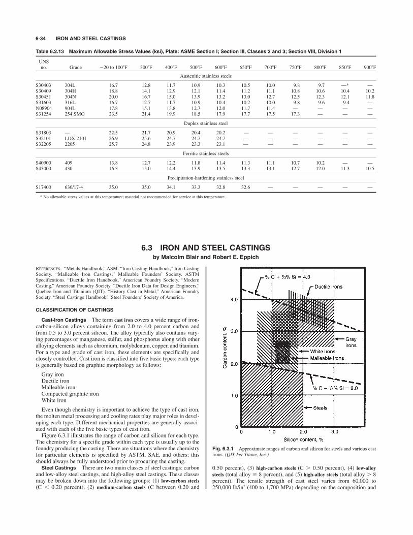
REFERENCES: “Metals Handbook,” ASM. “Iron Casting Handbook,” Iron CastingSociety. “Malleable Iron Castings,” Malleable Founders’ Society. ASTMSpecifications. “Ductile Iron Handbook,” American Foundry Society. “ModernCasting,” American Foundry Society. “Ductile Iron Data for Design Engineers,”Quebec Iron and Titanium (QIT). “History Cast in Metal,” American FoundrySociety. “Steel Castings Handbook,” Steel Founders’ Society of America.
CLASSIFICATION OF CASTINGS
Cast-lron Castings The term cast iron covers a wide range of iron-carbon-silicon alloys containing from 2.0 to 4.0 percent carbon andfrom 0.5 to 3.0 percent silicon. The alloy typically also contains vary-ing percentages of manganese, sulfur, and phosphorus along with otheralloying elements such as chromium, molybdenum, copper, and titanium.For a type and grade of cast iron, these elements are specifically andclosely controlled. Cast iron is classified into five basic types; each typeis generally based on graphite morphology as follows:
Gray ironDuctile iron Malleable iron Compacted graphite ironWhite iron
Even though chemistry is important to achieve the type of cast iron,the molten metal processing and cooling rates play major roles in devel-oping each type. Different mechanical properties are generally associ-ated with each of the five basic types of cast iron.Figure 6.3.1 illustrates the range of carbon and silicon for each type.
The chemistry for a specific grade within each type is usually up to thefoundry producing the casting. There are situations where the chemistryfor particular elements is specified by ASTM, SAE, and others; thisshould always be fully understood prior to procuring the casting.Steel Castings There are two main classes of steel castings: carbon
and low-alloy steel castings, and high-alloy steel castings. These classesmay be broken down into the following groups: (1) low-carbon steels
(C ) 0.20 percent), (2) medium-carbon steels (C between 0.20 and
6-34 IRON AND STEEL CASTINGS
Table 6.2.13 Maximum Allowable Stress Values (ksi), Plate: ASME Section I; Section III, Classes 2 and 3; Section VIII, Division 1
UNSno. Grade %20 to 1008F 3008F 4008F 5008F 6008F 6508F 7008F 7508F 8008F 8508F 9008F
Austenitic stainless steels
S30403 304L 16.7 12.8 11.7 10.9 10.3 10.5 10.0 9.8 9.7 —* —S30409 304H 18.8 14.1 12.9 12.1 11.4 11.2 11.1 10.8 10.6 10.4 10.2S30451 304N 20.0 16.7 15.0 13.9 13.2 13.0 12.7 12.5 12.3 12.1 11.8S31603 316L 16.7 12.7 11.7 10.9 10.4 10.2 10.0 9.8 9.6 9.4 —N08904 904L 17.8 15.1 13.8 12.7 12.0 11.7 11.4 — — — —S31254 254 SMO 23.5 21.4 19.9 18.5 17.9 17.7 17.5 17.3 — — —
Duplex stainless steel
S31803 — 22.5 21.7 20.9 20.4 20.2 — — — — — —S32101 LDX 2101 26.9 25.6 24.7 24.7 24.7 — — — — — —S32205 2205 25.7 24.8 23.9 23.3 23.1 — — — — — —
Ferritic stainless steels
S40900 409 13.8 12.7 12.2 11.8 11.4 11.3 11.1 10.7 10.2 — —S43000 430 16.3 15.0 14.4 13.9 13.5 13.3 13.1 12.7 12.0 11.3 10.5
Precipitation-hardening stainless steel
S17400 630/17-4 35.0 35.0 34.1 33.3 32.8 32.6 — — — — —
* No allowable stress values at this temperature; material not recommended for service at this temperature.
6.3 IRON AND STEEL CASTINGSby Malcolm Blair and Robert E. Eppich
Fig. 6.3.1 Approximate ranges of carbon and silicon for steels and various castirons. (QIT-Fer Titane, Inc.)
0.50 percent), (3) high-carbon steels (C ' 0.50 percent), (4) low-alloy
steels (total alloy * 8 percent), and (5) high-alloy steels (total alloy ' 8percent). The tensile strength of cast steel varies from 60,000 to250,000 lb/in2 (400 to 1,700 MPa) depending on the composition and
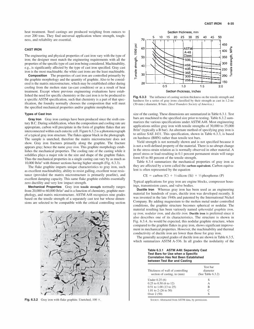
CAST IRON 6-35
heat treatment. Steel castings are produced weighing from ounces toover 200 tons. They find universal application where strength, tough-ness, and reliability are essential.
CAST IRON
The engineering and physical properties of cast iron vary with the type ofiron; the designer must match the engineering requirements with all theproperties of the specific type of cast iron being considered. Machinability,e.g., is significantly affected by the type of cast iron specified. Gray castiron is the most machinable; the white cast irons are the least machinable.Composition The properties of cast iron are controlled primarily by
the graphite morphology and the quantity of graphite. Also to be consid-ered is the matrix microstructure, which may be established either duringcooling from the molten state (as-cast condition) or as a result of heattreatment. Except where previous engineering evaluations have estab-lished the need for specific chemistry or the cast iron is to be produced toa specific ASTM specification, such that chemistry is a part of that spec-ification, the foundry normally chooses the composition that will meetthe specified mechanical properties and/or graphite morphology.
Types of Cast Iron
Gray Iron Gray iron castings have been produced since the sixth cen-tury B.C. During solidification, when the composition and cooling rate areappropriate, carbon will precipitate in the form of graphite flakes that areinterconnected within each eutectic cell. Figure 6.3.2 is a photomicrographof a typical gray iron structure. The flakes appear black in the photograph.The sample is unetched; therefore the matrix microstructure does notshow. Gray iron fractures primarily along the graphite. The fractureappears gray; hence the name gray iron. This graphite morphology estab-lishes the mechanical properties. The cooling rate of the casting while itsolidifies plays a major role in the size and shape of the graphite flakes.Thus the mechanical properties in a single casting can vary by as much as10,000 lb/in2 with thinner sections having higher strength (Fig. 6.3.3).The flake graphite imparts unique characteristics to gray iron, such
as excellent machinability, ability to resist galling, excellent wear resis-tance (provided the matrix microstructure is primarily pearlite), andexcellent damping capacity. This same flake graphite exhibits essentiallyzero ductility and very low impact strength.Mechanical Properties Gray iron tensile strength normally ranges
from 20,000 to 60,000 lb/in2 and is a function of chemistry, graphite mor-phology, and matrix microstructure. ASTM A48 recognizes nine gradesbased on the tensile strength of a separately cast test bar whose dimen-sions are selected to be compatible with the critical controlling section
size of the casting. These dimensions are summarized in Table 6.3.1. Testbars are machined to the specified size prior to testing. Table 6.3.2 sum-marizes the various specifications under ASTM A48. Most engineeringapplications utilize gray iron with tensile strengths of 30,000 to 35,000lb/in2 (typically a B bar). An alternate method of specifying gray iron isto utilize SAE J431. This specification, shown in Table 6.3.3, is basedon hardness (BHN) rather than tensile test bars.Yield strength is not normally shown and is not specified because it
is not a well-defined property of the material. There is no abrupt changein the stress-strain relation as is normally observed in other material. Aproof stress or load resulting in 0.1 percent permanent strain will rangeform 65 to 80 percent of the tensile strength.Table 6.3.4 summarizes the mechanical properties of gray iron as
they are affected by a term called the carbon equivalent. Carbon equiva-lent is often represented by the equation
Typical applications for gray iron are engine blocks, compressor hous-ings, transmission cases, and valve bodies.Ductile Iron Whereas gray iron has been used as an engineering
material for hundreds of years, ductile iron was developed recently. Itwas invented in the late 1940s and patented by the International NickelCompany. By adding magnesium to the molten metal under controlledconditions, the graphite structure becomes spherical or nodular. Thematerial resulting has been variously named spheroidal graphite iron,sg iron, nodular iron, and ductile iron. Ductile iron is preferred since italso describes one of its characteristics. The structure is shown inFig. 6.3.4. As would be expected, this nodular graphite structure, whencompared to the graphite flakes in gray iron, shows significant improve-ment in mechanical properties. However, the machinability and thermalconductivity of ductile iron are lower than those for gray iron.The generally accepted grades of ductile iron are shown in Table 6.3.5,
which summarizes ASTM A-536. In all grades the nodularity of the
CE 5 carbon sCd 1 1⁄3 silicon sSid 1 1⁄3 phosphorus sPd
Fig. 6.3.2 Gray iron with flake graphite. Unetched, 100 #.
Fig. 6.3.3 The influence of casting section thickness on the tensile strength andhardness for a series of gray irons classified by their strength as cast in 1.2-in-(30-mm-) diameter, B bars. (Steel Founders Society of America.)
Table 6.3.1 ASTM A48: Separately CastTest Bars for Use when a SpecificCorrelation Has Not Been Establishedbetween Test Bar and Casting
Test barThickness of wall of controlling diametersection of casting, in (mm) (See Table 6.3.2)
Under 0.25 (6) S0.25 to 0.50 (6 to 12) A0.51 to 1.00 (13 to 25) B1.01 to 2 (26 to 50) COver 2 (50) S
SOURCE: Abstracted from ASTM data, by permission.
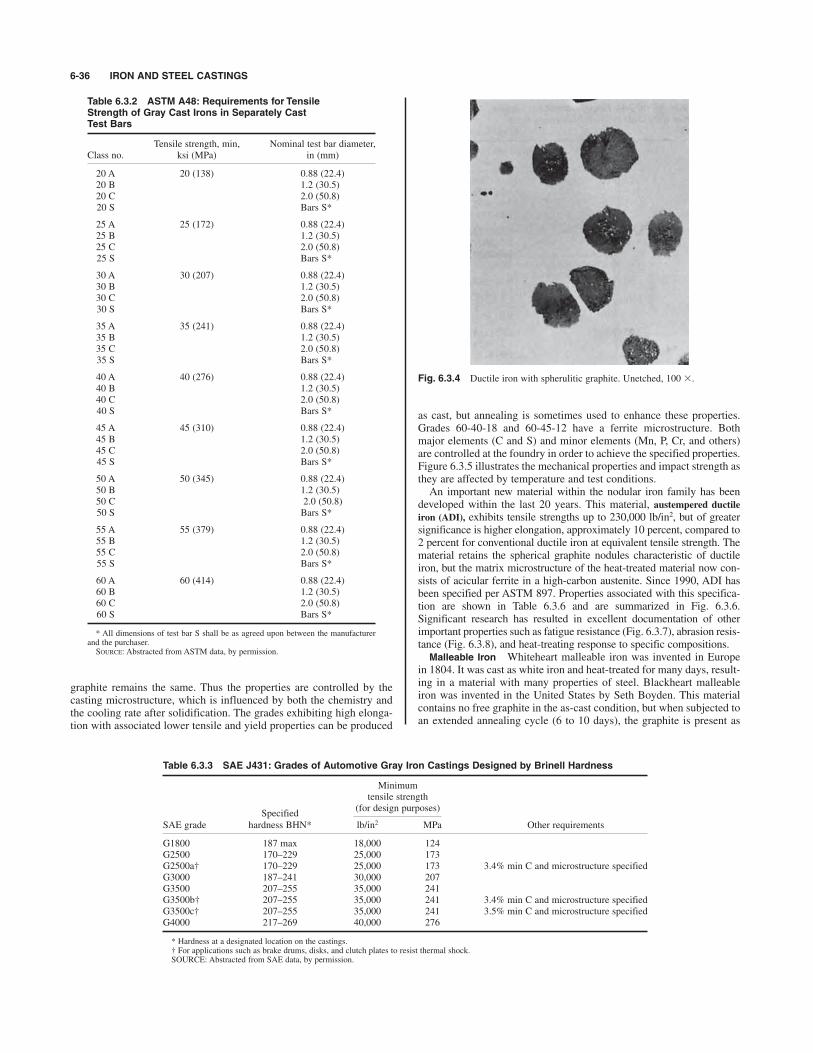
graphite remains the same. Thus the properties are controlled by thecasting microstructure, which is influenced by both the chemistry andthe cooling rate after solidification. The grades exhibiting high elonga-tion with associated lower tensile and yield properties can be produced
as cast, but annealing is sometimes used to enhance these properties.Grades 60-40-18 and 60-45-12 have a ferrite microstructure. Bothmajor elements (C and S) and minor elements (Mn, P, Cr, and others)are controlled at the foundry in order to achieve the specified properties.Figure 6.3.5 illustrates the mechanical properties and impact strength asthey are affected by temperature and test conditions. An important new material within the nodular iron family has been
developed within the last 20 years. This material, austempered ductile
iron (ADI), exhibits tensile strengths up to 230,000 lb/in2, but of greatersignificance is higher elongation, approximately 10 percent, compared to2 percent for conventional ductile iron at equivalent tensile strength. Thematerial retains the spherical graphite nodules characteristic of ductileiron, but the matrix microstructure of the heat-treated material now con-sists of acicular ferrite in a high-carbon austenite. Since 1990, ADI hasbeen specified per ASTM 897. Properties associated with this specifica-tion are shown in Table 6.3.6 and are summarized in Fig. 6.3.6.Significant research has resulted in excellent documentation of otherimportant properties such as fatigue resistance (Fig. 6.3.7), abrasion resis-tance (Fig. 6.3.8), and heat-treating response to specific compositions.Malleable Iron Whiteheart malleable iron was invented in Europe
in 1804. It was cast as white iron and heat-treated for many days, result-ing in a material with many properties of steel. Blackheart malleableiron was invented in the United States by Seth Boyden. This materialcontains no free graphite in the as-cast condition, but when subjected toan extended annealing cycle (6 to 10 days), the graphite is present as
6-36 IRON AND STEEL CASTINGS
Table 6.3.2 ASTM A48: Requirements for TensileStrength of Gray Cast Irons in Separately Cast Test Bars
Tensile strength, min, Nominal test bar diameter,Class no. ksi (MPa) in (mm)
20 A 20 (138) 0.88 (22.4)20 B 1.2 (30.5)20 C 2.0 (50.8)20 S Bars S*
25 A 25 (172) 0.88 (22.4)25 B 1.2 (30.5)25 C 2.0 (50.8)25 S Bars S*
30 A 30 (207) 0.88 (22.4)30 B 1.2 (30.5)30 C 2.0 (50.8)30 S Bars S*
35 A 35 (241) 0.88 (22.4)35 B 1.2 (30.5)35 C 2.0 (50.8)35 S Bars S*
40 A 40 (276) 0.88 (22.4)40 B 1.2 (30.5)40 C 2.0 (50.8)40 S Bars S*
45 A 45 (310) 0.88 (22.4)45 B 1.2 (30.5)45 C 2.0 (50.8)45 S Bars S*
50 A 50 (345) 0.88 (22.4)50 B 1.2 (30.5)50 C 2.0 (50.8)50 S Bars S*
55 A 55 (379) 0.88 (22.4)55 B 1.2 (30.5)55 C 2.0 (50.8)55 S Bars S*
60 A 60 (414) 0.88 (22.4)60 B 1.2 (30.5)60 C 2.0 (50.8)60 S Bars S*
* All dimensions of test bar S shall be as agreed upon between the manufacturerand the purchaser.SOURCE: Abstracted from ASTM data, by permission.
Table 6.3.3 SAE J431: Grades of Automotive Gray Iron Castings Designed by Brinell Hardness
Minimumtensile strength
Specified(for design purposes)
SAE grade hardness BHN* lb/in2 MPa Other requirements
G1800 187 max 18,000 124G2500 170–229 25,000 173G2500a† 170–229 25,000 173 3.4% min C and microstructure specifiedG3000 187–241 30,000 207G3500 207–255 35,000 241G3500b† 207–255 35,000 241 3.4% min C and microstructure specifiedG3500c† 207–255 35,000 241 3.5% min C and microstructure specifiedG4000 217–269 40,000 276
* Hardness at a designated location on the castings.† For applications such as brake drums, disks, and clutch plates to resist thermal shock.SOURCE: Abstracted from SAE data, by permission.
Fig. 6.3.4 Ductile iron with spherulitic graphite. Unetched, 100 #.

CAST IRON 6-37
irregularly shaped nodules called temper carbon (Fig. 6.3.9). All mal-leable iron castings produced currently are of blackheart malleable iron;the terms blackheart and whiteheart are obsolete.The properties of several grades of malleable iron are shown in Table
6.3.7. The properties are similar to those of ductile iron, but the anneal-ing cycles still range from 16 to 30 h. Production costs are higher thanfor ductile iron, so that virtually all new engineered products aredesigned to be of ductile iron. Malleable iron accounts for only 3 per-cent of total cast-iron production and is used mainly for pipe and elec-trical fittings and replacements for existing malleable-iron castings.Compacted Graphite Iron Compacted graphite iron was developed
in the mid-1970s. It is a controlled class of iron in which the graphite takesa form between that in gray iron and that in ductile iron. Figure 6.3.10
shows the typical graphite structure that is developed during casting. Itwas desired to produce a material that, without extensive alloying,would be stronger than the highest-strength grades of gray iron butwould be more machinable than ductile iron. These objectives weremet. The properties of the various grades of compacted iron are sum-marized in Table 6.3.8, which summarizes ASTM A842. Several otherproperties of this material should be considered. For example, itsgalling resistance is superior to that of ductile iron, and it is attractivefor hydraulic applications; its thermal conductivity is superior to that ofductile iron but inferior to that of gray iron. Compacted graphite ironproperties have resulted in its applications to satisfy a number of uniquerequirements.White Iron When white iron solidifies, virtually all the carbon
appears in the form of carbides. White irons are hard and brittle, andthey break with a white fracture. These irons are usually alloyed withchromium and nickel; Table 6.3.9 summarizes ASTM A532. Theirhardness is in the range of 500 to 600 BHN. The specific alloying thatis required is a function of section size and application; there must be
Fig. 6.3.5 Effect of temperature on low-temperature properties of ferritic duc-tile iron. (QIT-Fer Titane, Inc.)
Table 6.3.4 Effect of Carbon Equivalent on Mechanical Properties of Gray Cast Irons
Tensile Modulus of elasticity Shear Endurance Compressive Brinell Izod impact,Carbon strength, in tension at load, Modulus of Deflection in strength, limit, strength, hardness, unnotched,equivalent lb/in2* lb/in2 # 106† rapture, lb/in2* 18-in span, in‡ lb/in2* lb/in2* lb/in2* 3,000-kg load ft " lb
4.8 20,400 8.0 48,300 0.370 29,600 10,000 72,800 146 3.64.6 22,400 8.7 49,200 0.251 33,000 11,400 91,000 163 3.64.5 25,000 9.7 58,700 0.341 35,500 11,800 95,000 163 4.94.3 29,300 10.5 63,300 0.141 37,000 12,300 90,900 179 2.24.1 32,500 13.6 73,200 0.301 44,600 16,500 128,800 192 4.24.0 35,100 13.3 77,000 0.326 47,600 17,400 120,800 196 4.43.7 40,900 14.8 84,200 0.308 47,300 19,600 119,100 215 3.93.3 47,700 20.0 92,000 0.230 60,800 25,200 159,000 266 4.4
*# 6.89 kPa. † # 0.00689 MPa. ‡ # 25.4 mm.
1⁄2
Table 6.3.5 ASTM A536: Ductile Irons. Tensile Requirements
Grade Grade Grade Grade Grade60-40-18 65-45-12 80-55-06 100-70-03 120-90-02
Tensile strength, min, lb/in2 60,000 65,000 80,000 100,000 120,000Tensile strength, min, MPa 414 448 552 689 827Yield strength, min, lb/in2 40,000 45,000 55,000 70,000 90,000Yield strength, min, MPa 276 310 379 483 621Elongation in 2 in or 50 mm, min, % 18 12 6.0 3.0 2.0
SOURCE: Abstracted from ASTM data, by permission.
Fig. 6.3.6 Austempered ductile iron mechanical properties. (QIT-Fer Titane,Inc.)

coordination between designer and foundry. These irons exhibit out-standing wear resistance and are used extensively in the mining indus-try for ballmill shell liners, balls, impellers, and slurry pumps.Specialty Irons There are a number of highly alloyed gray and duc-
tile iron grades of cast iron. These grades typically contain between 20 and30 percent nickel along with other elements such as chromium andmolybdenum. They have the graphite morphology characteristic ofconventional gray or ductile iron, but alloying imparts significantlyenhanced performance when wear resistance or corrosion resistance isrequired. Tables 6.3.10 and 6.3.11 summarize ASTM A436 foraustenitic gray iron and ASTM A439 for austenitic ductile iron. Thisfamily of alloys is best known by its trade name Ni-Resist. Corrosionresistance of several of Ni-Resist alloys is summarized in Tables 6.3.12
6-38 IRON AND STEEL CASTINGS
Table 6.3.7 SAE J158a: Malleable Irons. MechanicalProperty Requirements
Grade Casting hardness Heat treatment
M 3210 156 BHN max. AnnealedM 4504 163–217 BHN Air-quenched and temperedM 5003 187–241 BHN Air-quenched and temperedM 5503 187–241 BHN Liquid-quenched and temperedM 7002 229–269 BHN Liquid-quenched and temperedM 8501 269–302 BHN Liquid-quenched and tempered
SOURCE: Abstracted from SAE data, by permission.
Table 6.3.6 ASTM A897: Austempered Ductile Irons. Mechanical Property Requirements
Grade Grade Grade Grade Grade125/80/10 150/100/7 175/125/4 200/155/1 230/185/—
Tensile strength, min, ksi 125 150 175 200 230Yield strength, min, ksi 80 100 125 155 185Elongation in 2 in, min % 10 7 4 1 *Impact energy, ft " lb† 75 60 45 25 *Typical hardness, BHN, kg/mm2‡ 269–321 302–363 341–444 388–477 444–555
* Elongation and impact requirements are not specified. Although grades 200/155/1 and 230/185/— are both primarily used for gear and wearresistance applications, Grade 200/155/1 has applications where some sacrifice in wear resistance is acceptable in order to provide a limited amount ofductility and toughness.† Unnotched charpy bars tested at 72 ! 78F. The values in the table are a minimum for the average of the highest three test values of the four tested
samples.‡ Hardness is not mandatory and is shown for information only.SOURCE: Abstracted from ASTM data, by permission.
Fig. 6.3.8 Comparison of pin abrasion test results of ADI, ductile iron, and twoabrasion-resistant steels. (QIT-Fer Titane, Inc.)
Fig. 6.3.9 Temper carbon form of graphite in malleable iron. Unetched, 100 #.
Fig. 6.3.7 Fatigue properties of notched and unnotched ADI. (QIT-Fer Titane,Inc.)
and 6.3.13. Castings made from these alloys exhibit performance com-parable to many stainless steels.
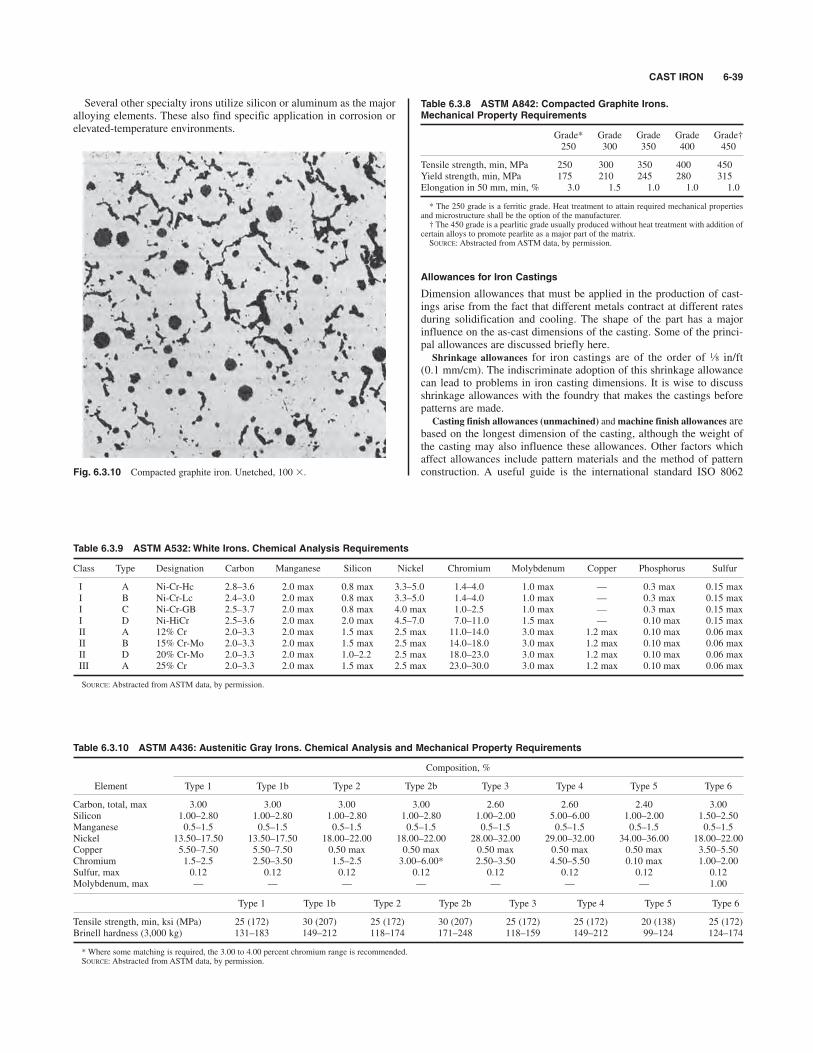
CAST IRON 6-39
Several other specialty irons utilize silicon or aluminum as the majoralloying elements. These also find specific application in corrosion orelevated-temperature environments.
Fig. 6.3.10 Compacted graphite iron. Unetched, 100 #.
Table 6.3.8 ASTM A842: Compacted Graphite Irons.Mechanical Property Requirements
Grade* Grade Grade Grade Grade†250 300 350 400 450
Tensile strength, min, MPa 250 300 350 400 450Yield strength, min, MPa 175 210 245 280 315Elongation in 50 mm, min, % 3.0 1.5 1.0 1.0 1.0
* The 250 grade is a ferritic grade. Heat treatment to attain required mechanical propertiesand microstructure shall be the option of the manufacturer.† The 450 grade is a pearlitic grade usually produced without heat treatment with addition of
certain alloys to promote pearlite as a major part of the matrix.SOURCE: Abstracted from ASTM data, by permission.
Allowances for Iron Castings
Dimension allowances that must be applied in the production of cast-ings arise from the fact that different metals contract at different ratesduring solidification and cooling. The shape of the part has a majorinfluence on the as-cast dimensions of the casting. Some of the princi-pal allowances are discussed briefly here.
Shrinkage allowances for iron castings are of the order of in/ft(0.1 mm/cm). The indiscriminate adoption of this shrinkage allowancecan lead to problems in iron casting dimensions. It is wise to discussshrinkage allowances with the foundry that makes the castings beforepatterns are made.
Casting finish allowances (unmachined) andmachine finish allowances arebased on the longest dimension of the casting, although the weight ofthe casting may also influence these allowances. Other factors whichaffect allowances include pattern materials and the method of patternconstruction. A useful guide is the international standard ISO 8062
1⁄8
Table 6.3.9 ASTM A532:White Irons. Chemical Analysis Requirements
Class Type Designation Carbon Manganese Silicon Nickel Chromium Molybdenum Copper Phosphorus Sulfur
I A Ni-Cr-Hc 2.8–3.6 2.0 max 0.8 max 3.3–5.0 1.4–4.0 1.0 max — 0.3 max 0.15 maxI B Ni-Cr-Lc 2.4–3.0 2.0 max 0.8 max 3.3–5.0 1.4–4.0 1.0 max — 0.3 max 0.15 maxI C Ni-Cr-GB 2.5–3.7 2.0 max 0.8 max 4.0 max 1.0–2.5 1.0 max — 0.3 max 0.15 maxI D Ni-HiCr 2.5–3.6 2.0 max 2.0 max 4.5–7.0 7.0–11.0 1.5 max — 0.10 max 0.15 maxII A 12% Cr 2.0–3.3 2.0 max 1.5 max 2.5 max 11.0–14.0 3.0 max 1.2 max 0.10 max 0.06 maxII B 15% Cr-Mo 2.0–3.3 2.0 max 1.5 max 2.5 max 14.0–18.0 3.0 max 1.2 max 0.10 max 0.06 maxII D 20% Cr-Mo 2.0–3.3 2.0 max 1.0–2.2 2.5 max 18.0–23.0 3.0 max 1.2 max 0.10 max 0.06 maxIII A 25% Cr 2.0–3.3 2.0 max 1.5 max 2.5 max 23.0–30.0 3.0 max 1.2 max 0.10 max 0.06 max
SOURCE: Abstracted from ASTM data, by permission.
Table 6.3.10 ASTM A436: Austenitic Gray Irons. Chemical Analysis and Mechanical Property Requirements
Composition, %
Element Type 1 Type 1b Type 2 Type 2b Type 3 Type 4 Type 5 Type 6
Carbon, total, max 3.00 3.00 3.00 3.00 2.60 2.60 2.40 3.00Silicon 1.00–2.80 1.00–2.80 1.00–2.80 1.00–2.80 1.00–2.00 5.00–6.00 1.00–2.00 1.50–2.50Manganese 0.5–1.5 0.5–1.5 0.5–1.5 0.5–1.5 0.5–1.5 0.5–1.5 0.5–1.5 0.5–1.5Nickel 13.50–17.50 13.50–17.50 18.00–22.00 18.00–22.00 28.00–32.00 29.00–32.00 34.00–36.00 18.00–22.00Copper 5.50–7.50 5.50–7.50 0.50 max 0.50 max 0.50 max 0.50 max 0.50 max 3.50–5.50Chromium 1.5–2.5 2.50–3.50 1.5–2.5 3.00–6.00* 2.50–3.50 4.50–5.50 0.10 max 1.00–2.00Sulfur, max 0.12 0.12 0.12 0.12 0.12 0.12 0.12 0.12Molybdenum, max — — — — — — — 1.00
Type 1 Type 1b Type 2 Type 2b Type 3 Type 4 Type 5 Type 6
Tensile strength, min, ksi (MPa) 25 (172) 30 (207) 25 (172) 30 (207) 25 (172) 25 (172) 20 (138) 25 (172)Brinell hardness (3,000 kg) 131–183 149–212 118–174 171–248 118–159 149–212 99–124 124–174
* Where some matching is required, the 3.00 to 4.00 percent chromium range is recommended.SOURCE: Abstracted from ASTM data, by permission.

(Castings—System of Dimensional Tolerances and MachiningAllowances). It is strongly recommended that designers discuss dimen-sional and machine finish allowance requirements with the foundry toavoid unnecessary costs.
STEEL CASTINGS
Composition There are five classes of commercial steel castings:low-carbon steels (C ) 0.20 percent), medium-carbon steels (C between0.20 and 0.50 percent), high-carbon steels (C ' 0.50 percent), low-alloy steels (total alloy * 8 percent), and high-alloy steels (total alloy' 8 percent).
Carbon Steel Castings Carbon steel castings contain less than 1.00percent C, along with other elements which may include Mn (0.50 to1.00 percent), Si (0.20 to 0.70 percent), max P (0.05 percent), and max S(0.06 percent). In addition, carbon steels, regardless of whether they arecast or wrought, may contain small percentages of other elements asresiduals from raw materials or additives incorporated in the steelmak-ing process. Low-Alloy Steel Castings In a low-alloy steel casting, the alloying
elements are present in percentages greater than the following: Mn,1.00; Si, 0.70; Cu, 0.50; Cr, 0.25; Mo, 0.10; V, 0.05; W, 0.05; and Ti,0.05. Limitations on phosphorus and sulfur contents apply to low-alloysteels as well as carbon steels unless they are specified to be different
6-40 IRON AND STEEL CASTINGS
Table 6.3.11 ASTM A439: Austenitic Ductile Irons. Chemical Analysis and Mechanical Property Requirements
Type
D-2* D-2B D-2C D-3* D-3A D-4 D-5 D-5B D-5S
Element Composition, %
Total carbon, max 3.00 3.00 2.90 2.60 2.60 2.60 2.40 2.40 2.30Silicon 1.50–3.00 1.50–3.00 1.00–3.00 1.00–2.80 1.00–2.80 5.00–6.00 1.00–2.80 1.00–2.80 4.90–5.50Manganese 0.70–1.25 0.70–1.25 1.80–2.40 1.00 max† l.00 max† 1.00 max† 1.00 max† 1.00 max† 1.00 maxPhosphorus, max 0.08 0.08 0.08 0.08 0.08 0.08 0.08 0.08 0.08Nickel 18.00–22.00 18.00–22.00 21.00–24.00 28.00–32.00 28.00–32.00 28.00–32.00 34.00–36.00 34.00–36.00 34.00–37.00Chromium 1.75–2.75 2.75–4.00 0.50 max† 2.50–3.50 1.00–1.50 4.50–5.50 0.10 max 2.00–3.00 1.75–2.25
Type
D-2 D-2B D-2C D-3 D-3A D-4 D-5 D-5B D-5S
Element Properties
Tensile strength, min, ksi (MPa) 58 (400) 58 (400) 58 (400) 55 (379) 55 (379) 60 (414) 55 (379) 55 (379) 65 (449)Yield strength (0.2% offset), min, ksi (MPa) 30 (207) 30 (207) 28 (193) 30 (207) 30 (207) — 30 (207) 30 (207) 30 (207)Elongation in 2 in or 50 mm, min, % 8.0 7.0 20.0 6.0 10.0 — 20.0 6.0 10Brinell hardness (3,000 kg) 139–202 148–211 121–171 139–202 131–193 202–273 131–185 139–193 131–193
* Additions of 0.7 to 1.0% of molybdenum will increase the mechanical properties above 8008F (4258C).† Not intentionally added.SOURCE: Abstracted from ASTM data, by permission.
Table 6.3.12 Corrosion Resistance of Ductile Ni-Resist Irons D-2 and D-2C
Penetration, in/yr
Corrosive media Type D-2C Type D-2
Ammonium chloride solution: 10% NH4Cl, pH 5.15, 13 days at 308C (868F), 6.25 ft/min 0.0280 0.0168Ammonium sulfate solution: 10% (NH4)2SO4, pH 5.7, 15 days at 308C (868F), 6.25 ft/min 0.0128 0.0111Ethylene vapors & splash: 38% ethylene glycol, 50% diethylene glycol, 4.5% H2O, 4% Na2SO4, 2.7% NaCl, 0.8% Na2CO3 $ 0.0023 0.0019*trace NaOH, pH 8 to 9, 85 days at 275–3008FFertilizer: commercial “5-10-5”, damp, 290 days at atmospheric temp — 0.0012Nickel chloride solution: 15% NiCl2, pH 5.3, 7 days at 308C (868F), 6.25 ft/min 0.0062 0.0040Phosphoric acid, 86%, aerated at 308C (868F), velocity 16 ft/min, 12 days 0.213 0.235Raw sodium chloride brine, 300 gpl of chlorides, 2.7 gpl CaO, 0.06 gpl NaOH, traces of NH3 & H2S, pH 6–6.5, 61 days at 508F, 0.0023 0.0020*0.1 to 0.2 fpsSeawater at 26.68C (808F), velocity 27 ft/s, 60-day test 0.039 0.018Soda & brine: 15.5% NaCl, 9.0% NaOH, 1.0% Na2SO4, 32 days at 1808F 0.0028 0.0015Sodium bisulfate solution: 10% NaHSO4, pH 1.3, 13 days at 308C (868F), 6.25 ft/min 0.0431 0.0444Sodium chloride solution: 5% NaCl, pH 5.6, 7 days at 308C (868F), 6.25 ft/min 0.0028 0.0019Sodium hydroxide:50% NaOH $ heavy conc. of suspended NaCl, 173 days at 558C (1318F), 40 gal/min. 0.0002 0.000250% NaOH saturated with salt, 67 days at 958C (2038F), 40 gal/min 0.0009 0.000650% NaOH, 10 days at 2608F, 4 days at 708F 0.0048 0.004930% NaOH $ heavy conc. of suspended NaCl, 82 days at 858C (1858F) 0.0004 0.000574% NaOH, 193/4 days, at 2608F 0.005 0.0056
Sodium sulfate solution: 10% Na2SO4, pH 4.0, 7 days at 308C (868F), 6.25 ft/min 0.0136 0.0130Sulfuric acid: 5%, at 308C (868F) aerated, velocity 14 ft/min, 4 days 0.120 0.104 Synthesis of sodium bicarbonate by Solvay process: 44% solid NaHCO3 slurry plus 200 gpl NH4Cl, 100 gpl NH4HCO3, 80 gpl 0.0009 0.0003NaCl, 8 gpl NaHCO3, 40 gpl CO2, 64 days at 308C (868F)Tap water aerated at 308F, velocity 16 ft/min, 28 days 0.0015 0.0023Vapor above ammonia liquor: 40% NH3, 9% CO2, 51% H2O, 109 days at 858C (1858F), low velocity 0.011 0.025Zinc chloride solution: 20% ZnCl2, pH 5.25, 13 days at 308C (868F), 6.25 ft/min 0.0125 0.0064
* Contains 1 % chromium.SOURCE: QIT-Fer Titane, Inc.

STEEL CASTINGS 6-41
for the purpose of producing some desired effect, e.g., free machining.Carbon and low-alloy steels account for approximately 85 percent ofthe steel castings produced in the United States.High-Alloy Steel Castings Steel castings with total alloy content
greater than 8 percent are generally considered to be high-alloy, andusually the steel castings industry requires that the composition containgreater than 11 percent Cr. This Cr content requirement eliminates thepotential confusion arising from including austenitic manganese steels(Hadfield) in this group. High-alloy steels include corrosion-resistant,heat-resistant, and duplex stainless steels. Many of the cast corrosion-resistant and duplex stainless steels are similar to the wrought stainlesssteels, but their performance may not be the same. Table 6.3.14 lists casthigh-alloy steels and similar wrought grades. Weight Range Steel castings weigh from a few ounces to over
200 tons. Steel castings may be made in any thickness down to 0.25 in(6 mm), and in special processes a thickness of 0.080 in (2 mm) has beenachieved. In investment castings, wall thicknesses of 0.060 in (1.5 mm)with sections tapering down to 0.030 in (0.75 mm) are common.
Table 6.3.13 Oxidation Resistance of Ductile Ni-Resist, Ni-Resist, Conventional and High-Silicon Ductile Irons, and Type 309Stainless Steel
Oxidation resistance
Penetration (in/yr)
Test 1 Test 2
Ductile iron (2.5 Si) 0.042 0.50Ductile iron (5.5 Si) 0.004 0.051Ductile Ni-Resist type D-2 0.042 0.175Ductile Ni-Resist type D-2C 0.07 —Ductile Ni-Resist type D-4 0.004 0.0Conventional Ni-Resist type 2 0.098 0.30Type 309 stainless steel 0.0 0.0
Test 1—Furnace atmosphere—air, 4,000 h at 1,3008F.Test 2—Furnace atmosphere—air, 600 h at 1,600–1,7008F, 600 h between
1,600–1,7008F, and 800–9008F, 600 h at 800–9008F.SOURCE: QIT-Fer Titane, Inc.
Table 6.3.14 ACI Designations for Heat- and Corrosion-Resistant High-Alloy Castings(See also Secs. 6.2 and 6.4.)
Wrought alloy Wrought alloyCast desig. UNS type* Cast desig. UNS type*
CA15 J91150 410 CW2M N26455 C4CA15M J91151 — CW6M N30107 —CA28MWV J91422 422 CW6MC N26625 625CA40 J91153 420 CW12MW N30002 CCA6NM J91540 F6NM CX2MW N26022 C22CA6N J91650 — CY5SnBiM N26055 —CB30 J91803 431 HA —CB7Cu-1 J92180 17-4 HC —CB7Cu-2 J92110 15-5 HD —CC50 J92615 446 HE —CD3MWCuN J93380 Zeron 100 HF —CD3MN J92205 2205 HH —CD4MCu J93370 255 HI —CD6MN J93371 — HK —CE3MN J93404 — HL —CE30 J93423 — HN —CE8MN J93345 — HP —CF3 J92500 304NL HP —CF8 J92600 304 HT —CF10SMnN J92972 Nitronic 60 HU —CF20 J92602 302 HW —CF3M J92800 316l HX —CF3MN J92804 316LN M25S N24025 —CF8M J92900 316 M30C N24130 —CF8C J92710 347 M30H N24030 —CF16F J92701 303 M35-1 N24135 400CG6MMN J93790 Nitronic 50 M35-2 N04020 400CG12 J93001 — N7M N30007 B2CG8M J93000 317 N12MV N30012 BCH20 J93402 309CK20 J94202 310CK3MCuN J93254 254SMOCN3MN J94651 AL6XNCN7M N08007 —CN7MS N02100 —CU5MCuC N08826 825
* Wrought alloy type references are listed only for the convenience of those who want corresponding wrought and cast grades.This table does not imply that the performance of the corresponding cast and wrought grades will be the same. Because the castalloy chemical composition ranges are not the same as the wrought composition ranges, buyers should use cast alloy designa-tions for proper identification of castings.† Common description, formerly used by AISI.‡ Proprietary trademark: ‡1 Armco, Inc, ‡2 Avesta Sheffield, ‡3 Allegheny Ludlum Corp.§ Common name used by two or more producers; not a trademark.¶ ASTM designation.NOTE: Most of the standard grades listed are covered for general applications by ASTM specifications.SOURCE: Steel Founders Society of America Handbook, 5th ed.
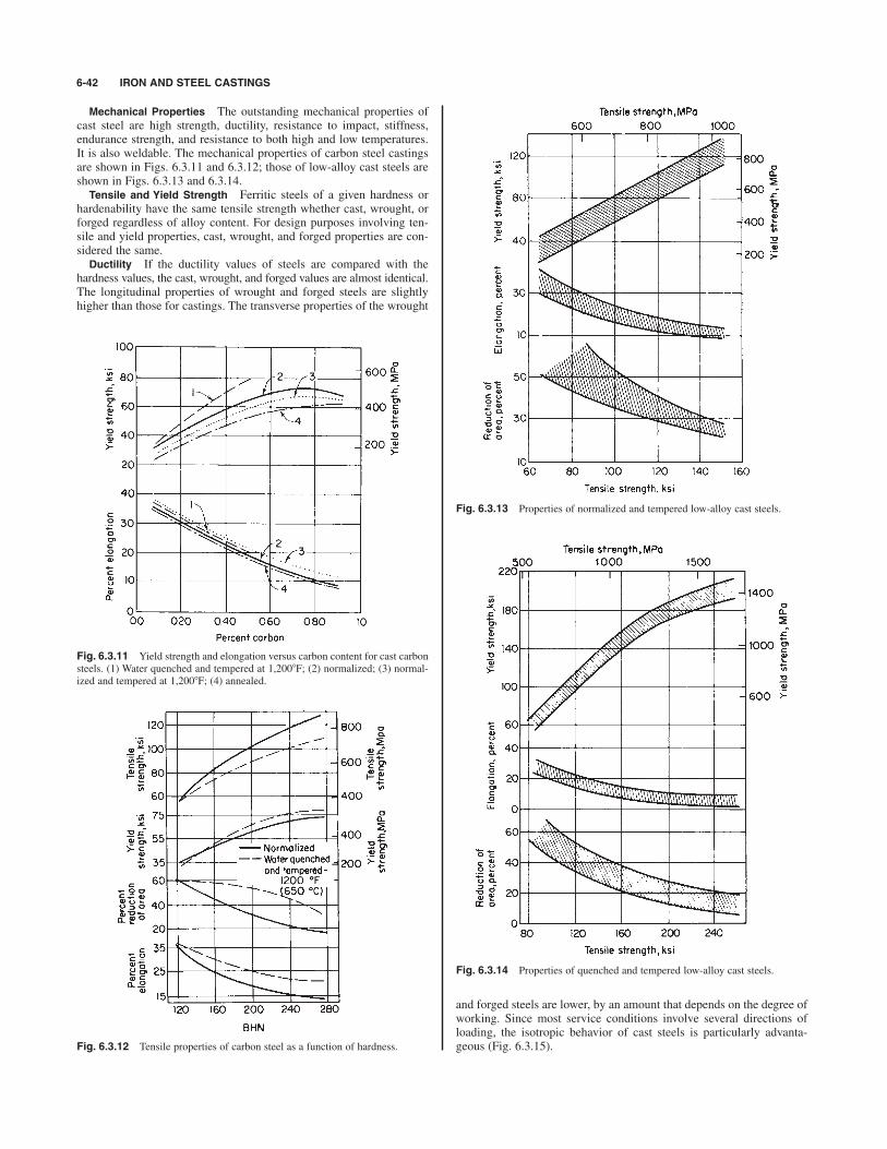
Mechanical Properties The outstanding mechanical properties ofcast steel are high strength, ductility, resistance to impact, stiffness,endurance strength, and resistance to both high and low temperatures.It is also weldable. The mechanical properties of carbon steel castingsare shown in Figs. 6.3.11 and 6.3.12; those of low-alloy cast steels areshown in Figs. 6.3.13 and 6.3.14.Tensile and Yield Strength Ferritic steels of a given hardness or
hardenability have the same tensile strength whether cast, wrought, orforged regardless of alloy content. For design purposes involving ten-sile and yield properties, cast, wrought, and forged properties are con-sidered the same.Ductility If the ductility values of steels are compared with the
hardness values, the cast, wrought, and forged values are almost identical.The longitudinal properties of wrought and forged steels are slightlyhigher than those for castings. The transverse properties of the wrought
6-42 IRON AND STEEL CASTINGS
Fig. 6.3.11 Yield strength and elongation versus carbon content for cast carbonsteels. (1) Water quenched and tempered at 1,2008F; (2) normalized; (3) normal-ized and tempered at 1,2008F; (4) annealed.
Fig. 6.3.12 Tensile properties of carbon steel as a function of hardness.
Fig. 6.3.13 Properties of normalized and tempered low-alloy cast steels.
Fig. 6.3.14 Properties of quenched and tempered low-alloy cast steels.
and forged steels are lower, by an amount that depends on the degree ofworking. Since most service conditions involve several directions ofloading, the isotropic behavior of cast steels is particularly advanta-geous (Fig. 6.3.15).

STEEL CASTINGS 6-43
Impact The notched-bar impact test is used often as a measure of thetoughness of materials. Cast steels have excellent impact properties at nor-mal and low temperatures. Generally wrought steels are tested in the direc-tion of rolling, show higher impact values than cast steels of similarcomposition. Transverse impact values will be 50 to 70 percent lower thanthese values. Cast steels do not show directional properties. If the direc-tional properties are averaged for wrought steels, the values obtained arecomparable to the values obtained for cast steels of similar composition.The hardenability of cast steels is influenced by composition and othervariables in the same manner as the hardenability of wrought steels. Theratio of the endurance limit to the tensile strength for cast steel varies from0.42 to 0.50, depending somewhat on the composition and heat treatmentof the steel. The notch-fatigue ratio varies from 0.28 to 0.32 for cast steelsand is the same for wrought steels (Fig. 6.3.16).
Fig. 6.3.15 Influence of forging reduction on anisotropy for a 0.35 percentcarbon wrought steel. Properties for a cast of 0.35 percent carbon steel are shownwith an asterisk for comparison purposes. (Steel Founders Society of AmericaHandbook, 5th ed.)
Fig. 6.3.16 Variations of endurance limit with tensile strength for comparablecarbon and low-alloy cast and wrought steels.
In wear testing, cast steels react similarly to wrought steels and givecorresponding values depending on composition, structure, and hardness.Carbon cast steels of approximately 0.50 percent C and low-alloy cast steelsof the chromium, chromium-molybdenum, nickel-chromium, chromium-vanadium, and medium-manganese types, all of which contain more than0.40 percent C, exhibit excellent resistance to wear in service.Corrosion Resistance Cast and wrought steels of similar composi-
tion and heat treatment appear to be equally resistant to corrosion in thesame environments. Small amounts of copper in cast steels increase theresistance of the steel to atmospheric corrosion. High-alloy steels ofchromium, chromium-nickel, and chromium-nickel-molybdenum typesare normally used for corrosion service.Heat Resistance Although not comparable to the high-alloy steels
of the nickel-chromium types developed especially for heat resistance,the 4.0 to 6.5 percent Cr cast steels, particularly with additions of 0.75to 1.25 percent W, or 0.40 to 0.70 percent Mo, and 0.75 to 1.00 percentTi, show good strength and considerable resistance to scaling up to1,0008F (5508C).Many cast high-alloy nickel-chromium steels have creep and rup-
ture properties superior to those of wrought materials. In many caseswrought versions of the cast grades are not available due to hot-workingdifficulties. These cast materials may be used in service conditions upto 2,0008F (1,1008C), with some grades capable of withstanding tem-peratures of 2,2008F (1,2008C).
Machinability of carbon and alloy cast steels is comparable to thatof wrought steels having equivalent strength, ductility, hardness, andsimilar microstructure. Factors influencing the machinability of caststeels are as follows: (1) Microstructure has a definite effect on machin-ability of cast steels. In some cases it is possible to improve machin-ability by as much as 100 to 200 percent through heat treatments whichalter the microstructure. (2) Generally speaking, hardness alone cannotbe taken as the criterion for predicting tool life in cutting cast steels.(3) In general, for a given structure, plain carbon steels machine betterthan alloy steels. (4) When machining cast carbon steel (1040) withcarbides, tool life varies with the ratio of ferrite to pearlite in themicrostructure of the casting, the 60 : 40 ratio resulting in optimum toollife. For equal tool life, the skin of a steel casting should be machinedat approximately one-half the cutting speed recommended for the basemetal. The machinability of various carbon and low-alloy cast steels isgiven in Table 6.3.15.
Welding steel castings presents the same problems as welding wroughtsteels. It is interesting to note that cast low-alloy steels show greater resis-tance to underbead cracking than their wrought counterparts.Purchase Specifications for Steel Castings Many steel castings
are purchased according to mechanical property specifications,although more frequent use of specifications which indicate the use ofsteel castings may be more helpful. Note that it is now possible to ordersteel castings as cast equivalents of the SAE/AISI chemical composi-tion ranges using ASTM A915. It is preferable to order steel castings toconform with national standards such as ASTM. ASTM standards areprepared by purchasers and suppliers and are well understood by steelfoundries. The property levels specified in ASTM specifications A27and A148 are shown in Table 6.3.16. Table 6.3.17 lists current applica-ble ASTM steel castings standards.Steel Melting Practice Steel for steel castings is produced com-
mercially by processes similar to those used for wrought steel produc-tion, but electric arc and electric induction melting furnacespredominate. Some steel foundries also use secondary refining processessuch as argon oxygen decarburization (AOD) and/or vacuum oxygen
degassing (VOD). Wire injection is also used selectively depending onservice and process requirements for the steel casting. In addition to thematerials listed in the ASTM standards, the steel casting industry willproduce compositions tailored especially for particular service applica-tions, and even in small quantity.
Allowances for Steel Castings
Dimensional allowances that must be applied in the production of cast-ings are due to the fact that different metals contract at different rates

during solidification and cooling. The shape of the part has a majorinfluence on the as-cast dimensions of the casting. Some of the princi-pal allowances are discussed briefly here.
Shrinkage allowances for steel castings vary from to in/ft(0.03 to 0.005 cm/cm). The amount most often used is in/ft(0.021 cm/cm), but if it is applied indiscriminately, it can lead to prob-lems in steel casting dimensions. The best policy is to discuss shrinkageallowances with the foundry that makes the castings before patterns aremade.Minimum Section Thickness The fluidity of steel when compared
to other metals is low. In order that all sections may be completelyfilled, a minimum value of section thickness must be adopted that is afunction of the largest dimension of the casting. These values are sug-gested for design use:
1⁄4
1⁄169⁄32
Casting finish allowances (unmachined) are based on the longestdimension of the casting, but the casting weight may also influencethese allowances. Other factors which affect allowances include patternmaterials and the method of pattern construction. Average values ofallowance as a function of pattern type are shown in Table 6.3.18; other
6-44 IRON AND STEEL CASTINGS
Max lengthMin section ofthickness section
in mm in cm
6 12 3013 50 1251⁄2
1⁄4
Table 6.3.15 Machinability Index for Cast Steels
Conventional Metcut*
Steel BHN Carbide HSS HSS Carbide
B1112 Free machining steel (wrought) 179 . . . 1001020 Annealed 122 10 90 160 4001020 Normalized 134 6 75 135 2301040 Double normalized 185 11 70 130 4001040 Normalized and annealed 175 10 75 135 3801040 Normalized 190 6 65 120 3251040 Normalized and oil-quenched 225 6 45 80 3101330 Normalized 187 2 40 75 1401330 Normalized and tempered 160 3 65 120 2304130 Annealed 175 4 55 95 2604130 Normalized and spheroidized 175 3 50 90 2004340 Normalized and annealed 200 3 35 60 2104340 Normalized and spheroidized 210 6 55 95 2904340 Quenched and tempered 300 2 25 45 2004340 Quenched and tempered 400 20 35 1808430 Normalized and tempered at 1,2008F (6608C) 200 3 50 90 2008430 Normalized and tempered at 1,2758F (7028C) 180 4 60 110 2408630 Normalized 240 2 40 75 1808630 Annealed 175 5 65 120 290
* The Metcut speed index number is the actual cutting speed (surface ft/min) which will give 1 h tool life in turning.
1⁄2
Table 6.3.16 ASTM Requirements for Steel Castings in A27 and A148
Tensile strength, Yield point min, Elongation, Reduction ofGrade min, ksi (MPa) ksi (MPa) min, % area, min, %
ASTM A27
U-60-30 60 (415) 30 (205) 22 3060-30 60 (415) 30 (205) 24 3565-35 65 (450) 35 (240) 24 3570-36 70 (485) 36 (250) 22 3070-40 70 (485) 40 (275) 22 30
ASTM A148
80–40 80 (550) 40 (275) 18 3080–50 80 (550) 50 (345) 22 3590–60 90 (620) 60 (415) 20 40105–85 105 (725) 85 (585) 17 35115–95 115 (795) 95 (655) 14 30130–115 130 (895) 115 (795) 11 25135–125 135 (930) 125 (860) 9 22150–135 150 (1,035) 135 (930) 7 18160–145 160 (1,105) 145 (1,000) 6 12165–150 165 (1,140) 150 (1,035) 5 20165–150L 165 (1,140) 150 (1,035) 5 20210–180 210 (1,450) 180 (1,240) 4 15210–180L 210 (1,450) 180 (1,240) 4 15260–210 260 (1,795) 210 (1,450) 3 6260–210L 260 (1,795) 210 (1,450) 3 6
SOURCE: Abstracted from ASTM data, by permission.
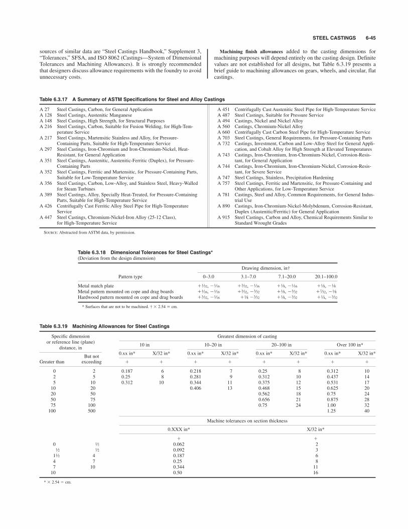
STEEL CASTINGS 6-45
Table 6.3.17 A Summary of ASTM Specifications for Steel and Alloy Castings
A 27 Steel Castings, Carbon, for General Application A 451 Centrifugally Cast Austenitic Steel Pipe for High-Temperature ServiceA 128 Steel Castings, Austenitic Manganese A 487 Steel Castings, Suitable for Pressure ServiceA 148 Steel Castings, High Strength, for Structural Purposes A 494 Castings, Nickel and Nickel AlloyA 216 Steel Castings, Carbon, Suitable for Fusion Welding, for High-Tem- A 560 Castings, Chromium-Nickel Alloy
perature Service A 660 Centrifugally Cast Carbon Steel Pipe for High-Temperature ServiceA 217 Steel Castings, Martensitic Stainless and Alloy, for Pressure- A 703 Steel Castings, General Requirements, for Pressure-Containing Parts
Containing Parts, Suitable for High-Temperature Service A 732 Castings, Investment, Carbon and Low-Alloy Steel for General Appli-A 297 Steel Castings, Iron-Chromium and Iron-Chromium-Nickel, Heat- cation, and Cobalt Alloy for High Strength at Elevated Temperatures
Resistant, for General Application A 743 Castings, Iron-Chromium, Iron-Chromium-Nickel, Corrosion-Resis-A 351 Steel Castings, Austenitic, Austenitic-Ferritic (Duplex), for Pressure- tant, for General Application
Containing Parts A 744 Castings, Iron-Chromium, Iron-Chromium-Nickel, Corrosion-Resis-A 352 Steel Castings, Ferritic and Martensitic, for Pressure-Containing Parts, tant, for Severe Service
Suitable for Low-Temperature Service A 747 Steel Castings, Stainless, Precipitation HardeningA 356 Steel Castings, Carbon, Low-Alloy, and Stainless Steel, Heavy-Walled A 757 Steel Castings, Ferritic and Martensitic, for Pressure-Containing and
for Steam Turbines Other Applications, for Low-Temperature ServiceA 389 Steel Castings, Alloy, Specially Heat-Treated, for Pressure-Containing A 781 Castings, Steel and Alloy, Common Requirements, for General Indus-
Parts, Suitable for High-Temperature Service trial UseA 426 Centrifugally Cast Ferritic Alloy Steel Pipe for High-Temperature A 890 Castings, Iron-Chromium-Nickel-Molybdenum, Corrosion-Resistant,
Service Duplex (Austenitic/Ferritic) for General ApplicationA 447 Steel Castings, Chromium-Nickel-Iron Alloy (25-12 Class), A 915 Steel Castings, Carbon and Alloy, Chemical Requirements Similar to
for High-Temperature Service Standard Wrought Grades
SOURCE: Abstracted from ASTM data, by permission.
Table 6.3.18 Dimensional Tolerances for Steel Castings*(Deviation from the design dimension)
Drawing dimension, in†
Pattern type 0–3.0 3.1–7.0 7.1–20.0 20.1–100.0
Metal match plate $ , % $ , % $ , % $ , %Metal pattern mounted on cope and drag boards $ , % $ , % $ , % $ , %Hardwood pattern mounted on cope and drag boards $ , % $ % $ , % $ , %
* Surfaces that are not to be machined. † # 2.54 cm.
3⁄321⁄43⁄321⁄83⁄321⁄81⁄163⁄32
1⁄87⁄323⁄321⁄83⁄323⁄321⁄161⁄16
1⁄81⁄81⁄161⁄81⁄163⁄321⁄161⁄32
Table 6.3.19 Machining Allowances for Steel Castings
Specific dimension Greatest dimension of castingor reference line (plane)
10 in 10–20 in 20–100 in Over 100 in*distance, in
0.xx in* X/32 in* 0.xx in* X/32 in* 0.xx in* X/32 in* 0.xx in* X/32 in*But not
$ $ $ $ $ $ $ $Greater than exceeding
0 2 0.187 6 0.218 7 0.25 8 0.312 102 5 0.25 8 0.281 9 0.312 10 0.437 145 10 0.312 10 0.344 11 0.375 12 0.531 1710 20 0.406 13 0.468 15 0.625 2020 50 0.562 18 0.75 2450 75 0.656 21 0.875 2875 100 0.75 24 1.00 32100 500 1.25 40
Machine tolerances on section thickness
0.XXX in* X/32 in*
$ $0 0.062 2
0.092 31 4 0.187 64 7 0.25 87 10 0.344 1110 0.50 16
* # 2.54 cm.
1⁄2
1⁄21⁄2
1⁄2
sources of similar data are “Steel Castings Handbook,” Supplement 3,“Tolerances,” SFSA, and ISO 8062 (Castings—System of DimensionalTolerances and Machining Allowances). It is strongly recommendedthat designers discuss allowance requirements with the foundry to avoidunnecessary costs.
Machining finish allowances added to the casting dimensions formachining purposes will depend entirely on the casting design. Definitevalues are not established for all designs, but Table 6.3.19 presents abrief guide to machining allowances on gears, wheels, and circular, flatcastings.

Use of Steel Castings
All industries use steel castings. They are used as wheels, sideframes,bolsters, and couplings in the railroad industry; rock crushers in themining and cement industries; components in construction vehicles;suspension parts and fifth wheels for trucks; valves; pumps; armor.High-alloy steel castings are used in highly corrosive environments inthe chemical, petrochemical, and paper industries. Generally, steel cast-ings are applied widely when strength, fatigue, and impact propertiesare required, as well as weldability, corrosion resistance, and high-temperature strength. Often, overall economy of fabrication will dictatea steel casting as opposed to a competing product.
Casting Design Maximum service and properties can be obtainedfrom castings only when they are properly designed. Design rules forcastings have been prepared in detail to aid design engineers in prepar-ing efficient designs. Engineers are referred to the following organiza-tions for the latest publications available:
Steel Founders’ Society of America, Crystal lake, IL, 60014.American Foundry Society, Schaumburg, IL 60173.Investment Casting Institute, Dallas, TX 75206.
6-46 NONFERROUS METALS AND ALLOYS; METALLIC SPECIALTIES
6.4 NONFERROUS METALS AND ALLOYS; METALLIC SPECIALTIES
REFERENCES: Current edition of “Metals Handbook,” American Society forMaterials. Current listing of applicable ASTM, AISI, and SAE Standards.Publications of the various metal-producing companies. Publications of the pro-fessional and trade associations which contain educational material and physicalproperty data for the materials promoted.
INTRODUCTION
by L. D. Kunsman and C. L. Carlson; Amended by Staff
Seven nonferrous metals are of primary commercial importance: copper,zinc, lead, tin, aluminum, nickel, and magnesium. Some 40 other ele-ments are frequently alloyed with these to make the commercially impor-tant alloys. There are also about 15 minor metals that have importantspecific uses. The properties of these elements are given in Table 6.4.1.(See also Secs. 4, 5, and 6.1.)Metallic Properties Metals are substances that characteristically
are opaque crystalline solids of high reflectivity having good electricaland thermal conductivities, a positive chemical valence, and, usually,the important combination of considerable strength and the ability toflow before fracture. These characteristics are exhibited by the metallicelements (e.g., iron, copper, aluminum, etc.), or pure metals, and bycombinations of elements (e.g., steel, brass, dural), or alloys.Metals arecomposed of many small crystals, which grow individually until theyfill the intervening spaces by abutting neighboring crystals. Althoughthe external shape of these crystals and their orientation with respect toeach other are usually random, within each such grain, or crystal, theatoms are arranged on a regular three-dimensional lattice. Most metalsare arranged according to one of the three common types of lattice, orcrystal structure: face-centered cubic, body-centered cubic, or hexago-nal close-packed. (See Table 6.4.1.)The several properties of metals are influenced to varying degrees by
the testing or service environment (temperature, surrounding medium)and the internal structure of the metal, which is a result of its chemi-cal composition and previous history such as casting, hot rolling, coldextrusion, annealing, and heat treatment. These relationships, and thediscussions below, are best understood in the framework of the severalphenomena that may occur in metals processing and service and theirgeneral effect on metallic structure and properties.Ores, Extractions, Refining All metals begin with the mining of
ores and are successively brought through suitable physical and chem-ical processes to arrive at commercially useful degrees of purity. At thehigher-purity end of this process sequence, scrap metal is frequentlycombined with that derived from ore. Availability of suitable ores andthe extracting and refining processes used are specific for each metaland largely determine the price of the metal and the impurities that areusually present in commercial metals.Melting Once a metal arrives at a useful degree of purity, it is
brought to the desired combination of shape and properties by a seriesof physical processes, each of which influences the internal structure of
the metal. The first of these is usually melting, during which several ele-ments can be combined to produce an alloy of the desired composition.Depending upon the metal, its container, the surrounding atmosphere,the addition of alloy-forming materials, or exposure to vacuum, variouschemical reactions may be utilized in the melting stage to achieve opti-mum results.Casting The molten metal of desired composition is poured into
some type of mold in which the heat of fusion is dissipated and the meltbecomes a solid of suitable shape for the next stage of manufacture.Such castings either are used directly (e.g., sand casting, die casting,permanent-mold casting) or are transferred to subsequent operations(e.g., ingots to rolling, billets to forging or extrusion). The principaladvantage of castings is their design flexibility and low cost. The typi-cal casting has, to a greater or lesser degree, a large crystal size (grainsize), extraneous inclusions from slag or mold, and porosity caused bygas evolution and/or shrinking during solidification. The foundryman’sart lies in minimizing the possible defects in castings while maximizingthe economies of the process.Metalworking (See also Sec. 13.) The major portion of all metals is
subjected to additional shape and size changes in the solid state. Thesemetalworking operations substantially alter the internal structure andeliminate many of the defects typical of castings. The usual sequenceinvolves first hot working and then, quite often, cold working. Somemetals are only hot-worked, some only cold-worked; most are bothhotand cold-worked. These terms have a special meaning in metallurgi-cal usage.A cast metal consists of an aggregate of variously oriented grains,
each one a single crystal. Upon deformation, the grains flow by aprocess involving the slip of blocks of atoms over each other, along def-inite crystallographic planes. The metal is hardened, strengthened, andrendered less ductile, and further deformation becomes more difficult.This is an important method of increasing the strength of nonferrousmetals. The effect of progressive cold rolling on brass (Fig. 6.4.1) istypical. Terms such as “soft,” “quarter hard,” “half hard,” and “fullhard” are frequently used to indicate the degree of hardening producedby such working. For most metals, the hardness resulting from coldworking is stable at room temperature, but with lead, zinc, or tin, it willdecrease with time.Upon annealing, or heating the cold-worked metal, the first effect is
to relieve macrostresses in the object without loss of strength; indeed,the strength is often increased slightly. Above a certain temperature,softening commences and proceeds rapidly with increase in tempera-ture (Fig. 6.4.2). The cold-worked distorted metal undergoes a changecalled recrystallization. New grains form and grow until they haveconsumed the old, distorted ones. The temperature at which this occursin a given time, called the recrystallization temperature, is lower andthe resulting grain size finer, the more severe the working of the origi-nal piece. If the original working is carried out above this temperature,
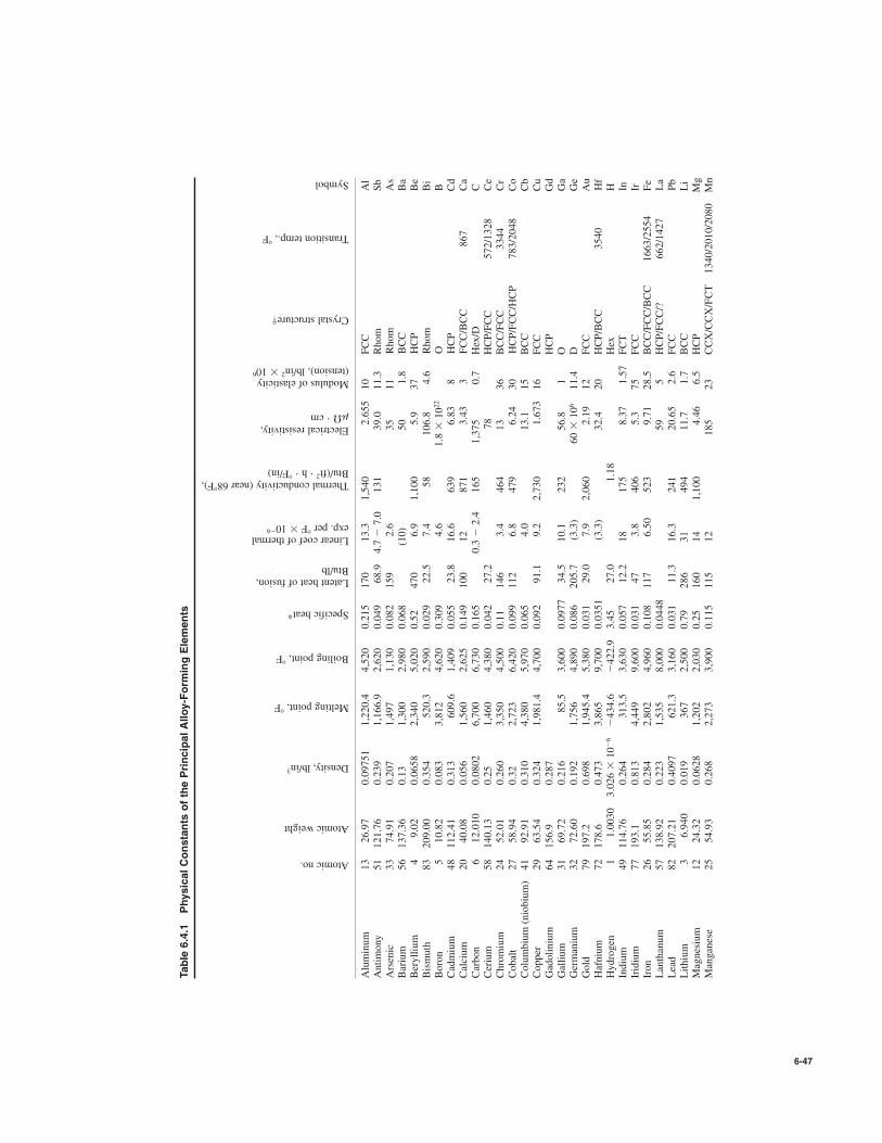
6-47
Table 6.4.1
Physical Constants of the Principal Alloy-Forming Elements
Aluminum
13
26.97
0.09751
1,220.4
4,520
0.215
170
13.3
1,540
2.655
10
FCC
Al
Antimony
51
121.76
0.239
1,166.9
2,620
0.049
68.9
4.7 % 7.0
131
39.0
11.3
Rhom
Sb
Arsenic
33
74.91
0.207
1,497
1,130
0.082
159
2.6
35
11
Rhom
As
Barium
56
137.36
0.13
1,300
2,980
0.068
(10)
50
1.8
BCC
Ba
Beryllium
49.02
0.0658
2,340
5,020
0.52
470
6.9
1,100
5.9
37
HCP
Be
Bismuth
83
209.00
0.354
520.3
2,590
0.029
22.5
7.4
58
106.8
4.6
Rhom
Bi
Boron
510.82
0.083
3,812
4,620
0.309
4.6
1.8#1022
OB
Cadmium
48
112.41
0.313
609.6
1,409
0.055
23.8
16.6
639
6.83
8HCP
Cd
Calcium
20
40.08
0.056
1,560
2,625
0.149
100
12
871
3.43
3FCC/BCC
867
Ca
Carbon
612.010
0.0802
6,700
6,730
0.165
0.3 %
2.4
165
1,375
0.7
Hex/D
CCerium
58
140.13
0.25
1,460
4,380
0.042
27.2
78
HCP/FCC
572/1328
Ce
Chromium
24
52.01
0.260
3,350
4,500
0.11
146
3.4
464
13
36
BCC/FCC
3344
Cr
Cobalt
27
58.94
0.32
2,723
6,420
0.099
112
6.8
479
6.24
30
HCP/FCC/HCP
783/2048
Co
Columbium (niobium)
41
92.91
0.310
4,380
5,970
0.065
4.0
13.1
15
BCC
Cb
Copper
29
63.54
0.324
1,981.4
4,700
0.092
91.1
9.2
2,730
1.673
16
FCC
Cu
Gadolinium
64
156.9
0.287
HCP
Gd
Gallium
31
69.72
0.216
85.5
3,600
0.0977
34.5
10.1
232
56.8
1O
Ga
Germanium
32
72.60
0.192
1,756
4,890
0.086
205.7
(3.3)
60#106
11.4
DGe
Gold
79
197.2
0.698
1,945.4
5,380
0.031
29.0
7.9
2,060
2.19
12
FCC
Au
Hafnium
72
178.6
0.473
3,865
9,700
0.0351
(3.3)
32.4
20
HCP/BCC
3540
Hf
Hydrogen
11.0030
3.026 #
10%6%434.6
%422.9
3.45
27.0
1.18
Hex
HIndium
49
114.76
0.264
313.5
3,630
0.057
12.2
18
175
8.37
1.57
FCT
InIridium
77
193.1
0.813
4,449
9,600
0.031
47
3.8
406
5.3
75
FCC
IrIron
26
55.85
0.284
2,802
4,960
0.108
117
6.50
523
9.71
28.5
BCC/FCC/BCC
1663/2554
Fe
Lanthanum
57
138.92
0.223
1,535
8,000
0.0448
59
5HCP/FCC/?
662/1427
La
Lead
82
207.21
0.4097
621.3
3,160
0.031
11.3
16.3
241
20.65
2.6
FCC
Pb
Lithium
36.940
0.019
367
2,500
0.79
286
31
494
11.7
1.7
BCC
Li
Magnesium
12
24.32
0.0628
1,202
2,030
0.25
160
14
1,100
4.46
6.5
HCP
Mg
Manganese
25
54.93
0.268
2,273
3,900
0.115
115
12
185
23
CCX/CCX/FCT
1340/2010/2080
Mn
Atomic no.
Atomic weight
Density, lb/in3
Melting point, 8F
Boiling point, 8F
Specific heat*
Latent heat of fusion,Btu/lb
Linear coef of thermalexp. per 8F#10
%6
Thermal conductivity (near 688F),Btu/(ft
2"h"+F/in)
Electrical resistivity,m&"cm
Modulus of elasticity(tension), lb/in
2#10
6
Crystal structure†
Transition temp., 8F
Symbol
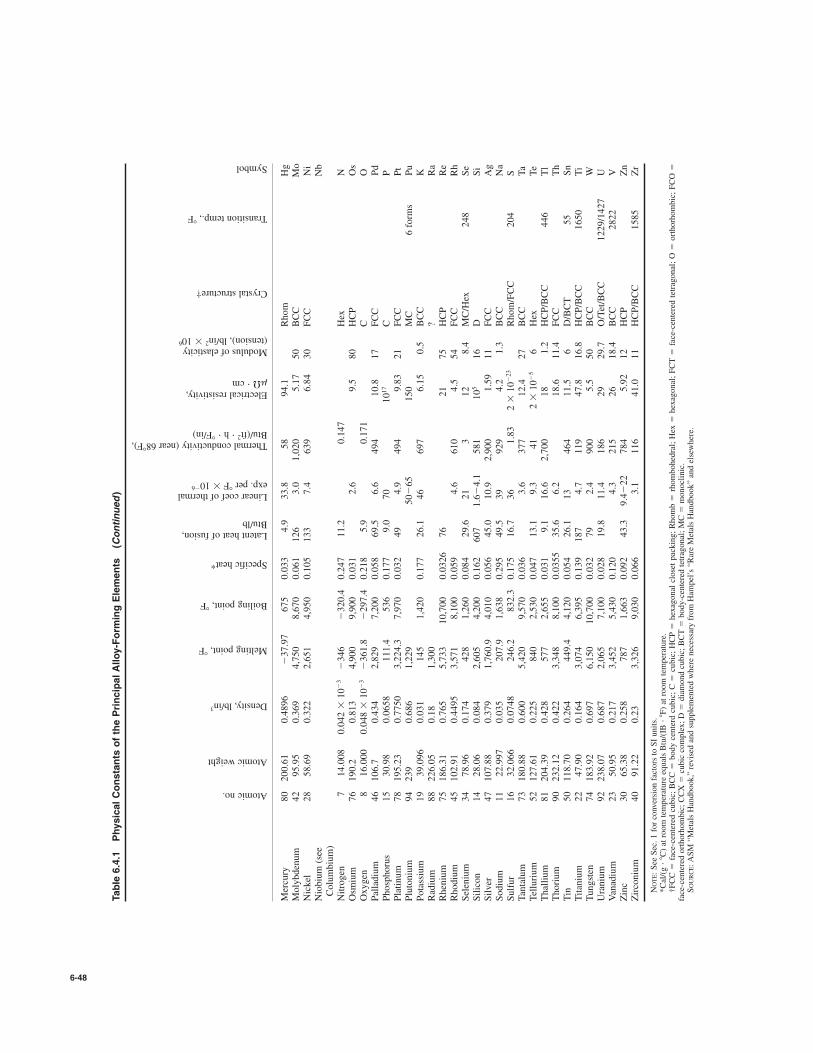
6-48
Atomic no.
Atomic weight
Density, lb/in3
Melting point, 8F
Boiling point, 8F
Specific heat*
Latent heat of fusion,Btu/lb
Linear coef of thermalexp. per 8F#10
%6
Thermal conductivity (near 688F),Btu/(ft
2"h"+F/in)
Electrical resistivity,m&"cm
Modulus of elasticity(tension), lb/in
2#10
6
Crystal structure†
Transition temp., 8F
Symbol
Table 6.4.1
Physical Constants of the Principal Alloy-Forming Elements
(Continued)
Mercury
80
200.61
0.4896
%37.97
675
0.033
4.9
33.8
58
94.1
Rhom
Hg
Molybdenum
42
95.95
0.369
4,750
8,670
0.061
126
3.0
1,020
5.17
50
BCC
Mo
Nickel
28
58.69
0.322
2,651
4,950
0.105
133
7.4
639
6.84
30
FCC
Ni
Niobium (see
Nb
Columbium)
Nitrogen
714.008
0.042 #
10%3%346
%320.4
0.247
11.2
0.147
Hex
NOsmium
76
190.2
0.813
4,900
9,900
0.031
2.6
9.5
80
HCP
Os
Oxygen
816.000
0.048 #
10%3%361.8
%297.4
0.218
5.9
0.171
CO
Palladium
46
106.7
0.434
2,829
7,200
0.058
69.5
6.6
494
10.8
17
FCC
Pd
Phosphorus
15
30.98
0.0658
111.4
536
0.177
9.0
70
1017
CP
Platinum
78
195.23
0.7750
3,224.3
7,970
0.032
49
4.9
494
9.83
21
FCC
Pt
Plutonium
94
239
0.686
1,229
50%65
150
MC
6 forms
Pu
Potassium
19
39.096
0.031
145
1,420
0.177
26.1
46
697
6.15
0.5
BCC
KRadium
88
226.05
0.18
1,300
?Ra
Rhenium
75
186.31
0.765
5,733
10,700
0.0326
76
21
75
HCP
Re
Rhodium
45
102.91
0.4495
3,571
8,100
0.059
4.6
610
4.5
54
FCC
Rh
Selenium
34
78.96
0.174
428
1,260
0.084
29.6
21
312
8.4
MC/Hex
248
Se
Silicon
14
28.06
0.084
2,605
4,200
0.162
607
1.6%4.1
581
105
16
DSi
Silver
47
107.88
0.379
1,760.9
4,010
0.056
45.0
10.9
2,900
1.59
11
FCC
Ag
Sodium
11
22.997
0.035
207.9
1,638
0.295
49.5
39
929
4.2
1.3
BCC
Na
Sulfur
16
32.066
0.0748
246.2
832.3
0.175
16.7
36
1.83
2 #
10%23
Rhom/FCC
204
STantalum
73
180.88
0.600
5,420
9,570
0.036
3.6
377
12.4
27
BCC
Ta
Tellurium
52
127.61
0.225
840
2,530
0.047
13.1
9.3
41
2 #
10%5
6Hex
Te
Thallium
81
204.39
0.428
577
2,655
0.031
9.1
16.6
2,700
18
1.2
HCP/BCC
446
Tl
Thorium
90
232.12
0.422
3,348
8,100
0.0355
35.6
6.2
18.6
11.4
FCC
Th
Tin
50
118.70
0.264
449.4
4,120
0.054
26.1
13
464
11.5
6D/BCT
55
Sn
Titanium
22
47.90
0.164
3,074
6,395
0.139
187
4.7
119
47.8
16.8
HCP/BCC
1650
Ti
Tungsten
74
183.92
0.697
6,150
10,700
0.032
79
2.4
900
5.5
50
BCC
WUranium
92
238.07
0.687
2,065
7,100
0.028
19.8
11.4
186
29
29.7
O/Tet/BCC
1229/1427
UVanadium
23
50.95
0.217
3,452
5,430
0.120
4.3
215
26
18.4
BCC
2822
VZinc
30
65.38
0.258
787
1,663
0.092
43.3
9.4%22
784
5.92
12
HCP
Zn
Zirconium
40
91.22
0.23
3,326
9,030
0.066
3.1
116
41.0
11
HCP/BCC
1585
Zr
NOTE: See Sec. 1for conversion factors to SI units.
*Cal/(g"8C) at room temperature equals Btu/(IB "
8F) at room temperature.
†FCC face-centered cubic; BCC
body centerd cubic; C
cubic; HCP
hexagonal closet packing; Rhomb
rhombohedral; Hex
hexagonal; FCT
face-centered tetragonal; O
orthorhombic; FCO
face-centered orthorhombic; CCX
cubic complex; D
diamond cubic; BCT
body-centered tetragonal; MC
monoclinic.
SOURCE: ASM “Metals Handbook,” revised and supplemented where necessary from Hampel’s“Rare Metals Handbook” and elsewhere.
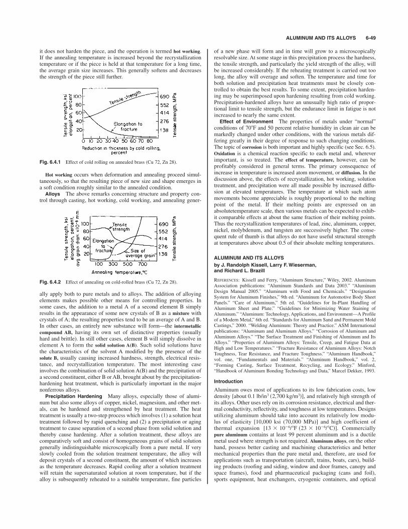
ALUMINUM AND ITS ALLOYS 6-49
it does not harden the piece, and the operation is termed hot working.
If the annealing temperature is increased beyond the recrystallizationtemperature or if the piece is held at that temperature for a long time,the average grain size increases. This generally softens and decreasesthe strength of the piece still further.
Fig. 6.4.1 Effect of cold rolling on annealed brass (Cu 72, Zn 28).
Hot working occurs when deformation and annealing proceed simul-taneously, so that the resulting piece of new size and shape emerges ina soft condition roughly similar to the annealed condition.Alloys The above remarks concerning structure and property con-
trol through casting, hot working, cold working, and annealing gener-
Fig. 6.4.2 Effect of annealing on cold-rolled brass (Cu 72, Zn 28).
ally apply both to pure metals and to alloys. The addition of alloyingelements makes possible other means for controlling properties. Insome cases, the addition to a metal A of a second element B simplyresults in the appearance of some new crystals of B as a mixture withcrystals of A; the resulting properties tend to be an average of A and B.In other cases, an entirely new substance will form—the intermetallic
compound AB, having its own set of distinctive properties (usuallyhard and brittle). In still other cases, element B will simply dissolve inelement A to form the solid solution A(B). Such solid solutions havethe characteristics of the solvent A modified by the presence of thesolute B, usually causing increased hardness, strength, electrical resis-tance, and recrystallization temperature. The most interesting caseinvolves the combination of solid solution A(B) and the precipitation ofa second constituent, either B or AB, brought about by the precipitation-hardening heat treatment, which is particularly important in the majornonferrous alloys.Precipitation Hardening Many alloys, especially those of alumi-
num but also some alloys of copper, nickel, magnesium, and other met-als, can be hardened and strengthened by heat treatment. The heattreatment is usually a two-step process which involves (1) a solution heattreatment followed by rapid quenching and (2) a precipitation or agingtreatment to cause separation of a second phase from solid solution andthereby cause hardening. After a solution treatment, these alloys arecomparatively soft and consist of homogeneous grains of solid solutiongenerally indistinguishable microscopically from a pure metal. If veryslowly cooled from the solution treatment temperature, the alloy willdeposit crystals of a second constituent, the amount of which increasesas the temperature decreases. Rapid cooling after a solution treatmentwill retain the supersaturated solution at room temperature, but if thealloy is subsequently reheated to a suitable temperature, fine particles
of a new phase will form and in time will grow to a microscopicallyresolvable size. At some stage in this precipitation process the hardness,the tensile strength, and particularly the yield strength of the alloy, willbe increased considerably. If the reheating treatment is carried out toolong, the alloy will overage and soften. The temperature and time forboth solution and precipitation heat treatments must be closely con-trolled to obtain the best results. To some extent, precipitation harden-ing may be superimposed upon hardening resulting from cold working.Precipitation-hardened alloys have an unusually high ratio of propor-tional limit to tensile strength, but the endurance limit in fatigue is notincreased to nearly the same extent. Effect of Environment The properties of metals under “normal”
conditions of 708F and 50 percent relative humidity in clean air can bemarkedly changed under other conditions, with the various metals dif-fering greatly in their degree of response to such changing conditions.The topic of corrosion is both important and highly specific (see Sec. 6.5).Oxidation is a chemical reaction specific to each metal and, whereverimportant, is so treated. The effect of temperature, however, can beprofitably considered in general terms. The primary consequence ofincrease in temperature is increased atom movement, or diffusion. In thediscussion above, the effects of recrystallization, hot working, solutiontreatment, and precipitation were all made possible by increased diffu-sion at elevated temperatures. The temperature at which such atommovements become appreciable is roughly proportional to the meltingpoint of the metal. If their melting points are expressed on anabsolutetemperature scale, then various metals can be expected to exhib-it comparable effects at about the same fraction of their melting points.Thus the recrystallization temperatures of lead, zinc, aluminum, copper,nickel, molybdenum, and tungsten are successively higher. The conse-quent rule of thumb is that alloys do not have useful structural strengthat temperatures above about 0.5 of their absolute melting temperatures.
ALUMINUM AND ITS ALLOYS
by J. Randolph Kissell, Larry F.Wieserman,and Richard L. Brazill
REFERENCES: Kissell and Ferry, “Aluminum Structure,” Wiley, 2002. AluminumAssociation publications: “Aluminum Standards and Data 2003.” “AluminumDesign Manual 2005.” “Aluminum with Food and Chemicals.” “DesignationSystem for Aluminum Finishes,” 9th ed. “Aluminum for Automotive Body SheetPanels.” “Care of Aluminum,” 5th ed. “Guidelines for In-Plant Handling ofAluminum Sheet and Plate.” “Guidelines for Minimizing Water Staining ofAluminum.” “Aluminum: Technology, Applications, and Environment—A Profileof a Modern Metal,” 6th ed. “Standards for Aluminum Sand and Permanent MoldCastings,” 2000. “Welding Aluminum: Theory and Practice.” ASM Internationalpublications: “Aluminum and Aluminum Alloys.” “Corrosion of Aluminum andAluminum Alloys.” “The Surface Treatment and Finishing of Aluminum and ItsAlloys.” “Properties of Aluminum Alloys: Tensile, Creep, and Fatigue Data atHigh and Low Temperatures.” “Fracture Resistance of Aluminum Alloys: NotchToughness, Tear Resistance, and Fracture Toughness.” “Aluminum Handbook,”vol. one, “Fundamentals and Materials.” “Aluminum Handbook,” vol. 2,“Forming Casting, Surface Treatment, Recycling, and Ecology.” Minford,“Handbook of Aluminum Bonding Technology and Data,” Marcel Dekker, 1993.
Introduction
Aluminum owes most of applications to its low fabrication costs, lowdensity and relatively high strength ofits alloys. Other uses rely on its corrosion resistance, electrical and ther-mal conductivity, reflectivity, and toughness at low temperatures. Designsutilizing aluminum should take into account its relatively low modu-lus of elasticity [10,000 ksi (70,000 MPa)] and high coefficient ofthermal expansion . Commerciallypure aluminum contains at least 99 percent aluminum and is a ductilemetal used where strength is not required. Aluminum alloys, on the otherhand, possess better casting and machining characteristics and bettermechanical properties than the pure metal and, therefore, are used forapplications such as transportation (aircraft, trains, boats, cars), build-ing products (roofing and siding, window and door frames, canopy andspace frames), food and pharmaceutical packaging (cans and foil),sports equipment, heat exchangers, cryogenic containers, and optical
[13 3 1026/8F s23 3 1026/8Cd]
[about 0.1 lb/in3 s2,700 kg/m3d],

components. A great variety of aluminum alloys and products are avail-able from producers; a useful guide to those that are commonly avail-able is the Aluminum Association publication “Aluminum Standardsand Data.”Aluminum alloys are divided into two classes: wrought alloys and
cast alloys, each with its own designation system specified in ANSIH35.1, “Alloy and Temper Designation Systems for Aluminum,” main-tained by the Aluminum Association.
Aluminum Alloy Designation Systems
Wrought aluminum and aluminum alloys are designated by a four-digitnumber. The first digit indicates the alloy group according to the mainalloying element as follows:
combination of strength and corrosion resistance. Alloys 6061 and 6063are used widely in structural applications, with 6061 providing greaterstrength at a slightly greater cost. Both alloys have good weldability.
7xxx Series: Heat-treating alloys in this series produces some of thehighest-strength aluminum alloys, frequently used in aircraft, such as7050, 7075, 7178, and 7475. The 7178-T651 plate has a minimum ten-sile strength of 84 ksi (580 MPa), the greatest of any commonly usedaluminum alloy. Most alloys of this group contain copper and so are notreadily welded, with 7005 being an exception.
Aluminum-lithium alloys have higher strength and modulus of elas-ticity than those of any of the other alloys, but cost about 4 times asmuch.
Cast aluminum and aluminum alloys are also designated by a four-digitnumber, but with a decimal point between the last two digits. The firstdigit indicates the alloy group according to the main alloying elementas follows:
6-50 NONFERROUS METALS AND ALLOYS; METALLIC SPECIALTIES
Designation no.
Aluminum, 99.00 percent and greater 1xxxAluminum alloys grouped by majoralloying elementsCopper 2xxxManganese 3xxxSilicon 4xxxMagnesium 5xxxMagnesium and silicon 6xxxZinc 7xxxOther element 8xxxUnused series 9xxx
The main alloying element is a good indicator of the properties of thealloy. For example, aluminum-copper alloys have greater strength butless corrosion resistance than pure aluminum. The second digit indi-cates modifications of the original alloy or impurity limits. For exam-ple, 2319 is identical to 2219 except for additional titanium to improvewelding characteristics. The last two digits of the 1xxx series alloysindicate the aluminum purity. “Aluminum Standards and Data” pro-vides the chemical compositions of commonly used alloys.Some common wrought alloys (by major alloying elements) and
applications are as follows:1xxx Series: Aluminum of 99 percent or greater is used in the elec-
trical and chemical industries for its high conductivity, corrosion resis-tance, and workability. It is available extruded or rolled and isstrengthened by cold working but not by heat treatment (see tempersbelow).
2xxx Series: These alloys are heat-treatable and some attain strengthscomparable to those of steel alloys. They are less corrosion resistantthan other aluminum alloys and thus are often clad with pure aluminumor an alloy of the 6xxx series (see alclad aluminum below). Alloys 2014and 2024 are popular, 2024 being perhaps the most widely used aircraftalloy. Many of the 2xxx alloys, including 2014, have poor weldingcharacteristics.
3xxx Series: Alloys in this series are strengthened only by coldworking. Alloys 3003, 3004, and 3105 are popular general-purposealloys with moderate strengths and good workability, and they are oftenused for sheet metal applications such as gutters, downspouts, roofing,and siding.
4xxx Series: Silicon added to alloys of this group lowers the meltingpoint, making these alloys suitable for use as weld filler wire (such as4043) and brazing alloys.
5xxx Series: These alloys attain moderate to high strength by coldworking and the addition to magnesium. They usually have the highestwelded strengths of aluminum alloys and good corrosion resistance.Alloys 5083, 5086, 5154, 5454, and 5456 are used in welded structures,including pressure vessels and ships. Alloy 5052 is a popular, low-costsheet metal alloy. For marine applications, 5xxx alloys of the -H116 and-H321 tempers are used for their corrosion resistance in freshwater andsaltwater.
6xxx Series: Although these alloys usually are not as strong as thosein the other heat-treatable series (2xxx and 7xxx), they offer a good
Designation no.
Aluminum, 99.00 percent and greater 1xx.xAluminum alloys grouped by majoralloying elementsCopper 2xx.xSilicon, with copper and/or magnesium 3xx.xSilicon 4xx.xMagnesium 5xx.xZinc 7xx.xTin 8xx.xOther element 9xx.xUnused series 6xx.x
For the 1xx.x series the second two digits indicate the aluminum puri-ty. The last digit indicates whether the product form is a casting (designat-ed by 0) or ingot (designated by 1 or 2) and is often dropped in commonusage for castings. A modification of the original alloy or impurity limitsis indicated by a serial letter prefix before the numerical designation. Anexample is A356, a modification of 356 with slightly tighter controls onthe minor alloying elements iron, copper, manganese, and zinc. The serialletters are assigned in alphabetical order but omitting I, O, Q, and X.
Tempers
The temper designation system applies to all aluminum and aluminumalloys, wrought or cast, except ingot. The temper designation followsthe alloy designation, separated by a hyphen. The basic tempers are des-ignated by letters as follows:
F as fabricated (no control over thermal conditions or strain hardening)
O annealed (the lowest strength temper of an alloy)H strain-hardened (applies to wrought products only)T thermally treated
The H and T tempers are followed by one or more numbers, e.g., T6or H14, indicating specific sequences of treatments. The properties ofalloys of H and T tempers are discussed further below.The alloys listed in Table 6.4.2 are divided into two classes: those
which may be strengthened by cold working (also called strain hardening)only (non-heat-treatable, designated by the H temper) and those whichmay be strengthened by thermal treatment (heat-treatable, designatedby the T temper).
Heat treatment (see Table 6.4.3) begins with a solution heat treatmentto put the soluble alloying elements into solid solution. For example, alloy6061 is heated to This is followed by rapidly droppingthe temperature, usually by quenching in water. At this point, the alloy isvery workable; but if it is held at room temperature or above, strengthgradually increases and ductility decreases as precipitation of constituentsof the supersaturated solution begins. This gradual change in properties iscalled natural aging. Alloys that have received solution heat treatment
9908F s5308Cd.
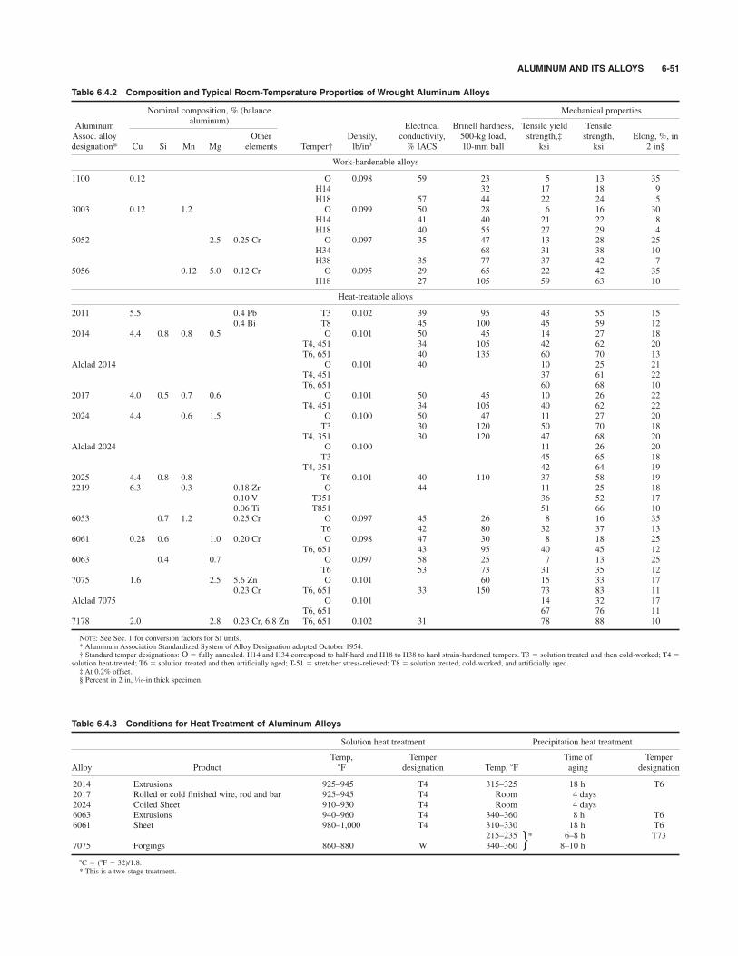
ALUMINUM AND ITS ALLOYS 6-51
Table 6.4.2 Composition and Typical Room-Temperature Properties of Wrought Aluminum Alloys
Nominal composition, % (balance Mechanical properties
Aluminumaluminum)
Electrical Brinell hardness, Tensile yield TensileAssoc. alloy Other Density, conductivity, 500-kg load, strength,‡ strength, Elong, %, in designation* Cu Si Mn Mg elements Temper† lb/in3 % IACS 10-mm ball ksi ksi 2 in§
Work-hardenable alloys
1100 0.12 O 0.098 59 23 5 13 35H14 32 17 18 9H18 57 44 22 24 5
3003 0.12 1.2 O 0.099 50 28 6 16 30H14 41 40 21 22 8H18 40 55 27 29 4
5052 2.5 0.25 Cr O 0.097 35 47 13 28 25H34 68 31 38 10H38 35 77 37 42 7
5056 0.12 5.0 0.12 Cr O 0.095 29 65 22 42 35H18 27 105 59 63 10
Heat-treatable alloys
2011 5.5 0.4 Pb T3 0.102 39 95 43 55 150.4 Bi T8 45 100 45 59 12
2014 4.4 0.8 0.8 0.5 O 0.101 50 45 14 27 18T4, 451 34 105 42 62 20T6, 651 40 135 60 70 13
Alclad 2014 O 0.101 40 10 25 21T4, 451 37 61 22T6, 651 60 68 10
2017 4.0 0.5 0.7 0.6 O 0.101 50 45 10 26 22T4, 451 34 105 40 62 22
2024 4.4 0.6 1.5 O 0.100 50 47 11 27 20T3 30 120 50 70 18
T4, 351 30 120 47 68 20Alclad 2024 O 0.100 11 26 20
T3 45 65 18T4, 351 42 64 19
2025 4.4 0.8 0.8 T6 0.101 40 110 37 58 192219 6.3 0.3 0.18 Zr O 44 11 25 18
0.10 V T351 36 52 170.06 Ti T851 51 66 10
6053 0.7 1.2 0.25 Cr O 0.097 45 26 8 16 35T6 42 80 32 37 13
6061 0.28 0.6 1.0 0.20 Cr O 0.098 47 30 8 18 25T6, 651 43 95 40 45 12
6063 0.4 0.7 O 0.097 58 25 7 13 25T6 53 73 31 35 12
7075 1.6 2.5 5.6 Zn O 0.101 60 15 33 170.23 Cr T6, 651 33 150 73 83 11
Alclad 7075 O 0.101 14 32 17T6, 651 67 76 11
7178 2.0 2.8 0.23 Cr, 6.8 Zn T6, 651 0.102 31 78 88 10
NOTE: See Sec. 1 for conversion factors for SI units.* Aluminum Association Standardized System of Alloy Designation adopted October 1954.† Standard temper designations: O fully annealed. H14 and H34 correspond to half-hard and H18 to H38 to hard strain-hardened tempers. T3 solution treated and then cold-worked; T4
solution heat-treated; T6 solution treated and then artificially aged; T-51 stretcher stress-relieved; T8 solution treated, cold-worked, and artificially aged.‡ At 0.2% offset.§ Percent in 2 in, -in thick specimen.1⁄16
Table 6.4.3 Conditions for Heat Treatment of Aluminum Alloys
Solution heat treatment Precipitation heat treatment
Temp, Temper Time of TemperAlloy Product 8F designation Temp, 8F aging designation
2014 Extrusions 925–945 T4 315–325 18 h T62017 Rolled or cold finished wire, rod and bar 925–945 T4 Room 4 days2024 Coiled Sheet 910–930 T4 Room 4 days6063 Extrusions 940–960 T4 340–360 8 h T66061 Sheet 980–1,000 T4 310–330 18 h T6
215–235 6–8 h T737075 Forgings 860–880 W 340–360 8–10 h
8C (8F % 32)/1.8.* This is a two-stage treatment.
j*

only are designated by a W or T temper and can be more readily cold-worked in this condition. Alloys that naturally age to a substantially sta-ble condition are designated with a T1 through T4 temper, depending onthe shaping process and degree of cold work imparted. Some materialsthat are to receive severe forming operations, such as cold-driven rivets,are held in this workable condition by storing below 328F (08C).By applying a second heat treatment, precipitation heat treatment or
artificial aging, at slightly elevated temperatures for a controlled time,further strengthening is achieved and properties are stabilized. Forexample, 6061 sheet is artificially aged when held at 3208F (1608C) for18 h. Material so treated is designated T6 temper. Artificial agingchanges the shape of the stress-strain curve above yield, thus affect-ing the tangent modulus of elasticity. For this reason, inelastic bucklingstrengths are determined differently for artificially aged alloys andalloys that have not received such treatment.
Strain hardening, also called cold working, is used to strengthen non-heat-treatable alloys, which cannot be strengthened by heat treatment.Non-heat-treatable alloys may be given a heat treatment to stabilizemechanical properties.
Annealing reduces an alloy’s strength to its lowest level but increasesductility. All wrought alloys may be annealed by heating to a prescribedtemperature. For example, 6061 is annealed when held at for approximately 2 to 3 h. Strengths are degraded whenever strain-hardened or artificially aged material is heated above about
The loss in strength is proportional to the time at elevated tem-perature. For example, 6061-T6 heated to for no longerthan 30 min or for 1,000 h exhibits less than a 5 percentdecrease in strength. Table 6.4.4 shows the effect of elevated tempera-tures on the strength of some alloy tempers.Minimum mechanical properties (usually tensile ultimate and yield
strengths and elongation) are specified for most wrought alloy tempersby the Aluminum Association in “Aluminum Standards and Data.”These minimum properties are also listed in ASTM specifications, butare grouped by ASTM by product (such as sheet and plate) rather thanby alloy. The minimum properties are established at levels at which 99percent of the material is expected to exceed at a confidence level of 95percent. The strengths of aluminum members subjected to axial force,bending, shear, and torsion under static and fatigue loads given in theAluminum Association’s “Aluminum Design Manual” are calculatedusing these minimum properties.
Product Forms
Extrusions, produced by pushing heated metal through a die opening, areamong the most useful aluminum products. A great variety of customshapes, as well as standard shapes such as I beams, angles, channels, pipe,rectangular tube, tees, and zees, are extruded. Extrusion cross sectionsmay be as large as those that fit with a 31-in (790-mm) circle, but com-monly available shapes are limited to about an 18-in (450-mm) circle.Alloys extruded include 1100, 1350, 2014, 2024, 2219, 3003, 5083, 5086,5154, 5454, 6005, 6061, 6063, 6082, 6101, 6105, 6351, 6463, 7005, 7050,7075, 7178, and 7475. The most common are the 6xxx series, especially6061 and 6063. Rod, bar, and wire are also produced rolled or cold-fin-ished as well as extruded. Tubes may be drawn or extruded.Flat-rolled products include foil, sheet, and plate. Foil is defined as
rolled product less than 0.006 in (through 0.15 mm) thick. Sheet is lessthan 0.25 in (through 6.3 mm) thick but not less than 0.006 in thick;aluminum sheet gauge thicknesses are different from those used forsteel, and decimal thicknesses are preferred when ordering. Sheet isavailable in flat panels (solid, perforated, or expanded metal) andcoiled. Plates are 0.25 in thick and greater, up to about 8 in (200 mm)thick. Minimum bend radii for sheet and plate depend on alloy and tem-per, but are generally greater than the bend radii for mild carbon steel.Commercial roofing and siding sheet are available in a number of pro-files, including corrugated, ribbed, and V-beam.Aluminum forgings are produced by open-die and closed-die meth-
ods. Minimum mechanical properties are not published for open-dieforgings, so structural applications usually require closed-die forgings.
3008F s1508Cd 4008F s2008Cd
s1208Cd.2508F
7758F s4158Cd
Like castings, forgings may be produced in complex shapes, but havemore uniform properties and better ductility than castings and are used forproducts such as wheels and aircraft components requiring high strength-to-weight ratios. For some forging alloys, minimum mechanical propertiesare slightly lower in directions other than parallel to the grain flow.Common forging alloys are 2014, 2219, 5083, 6061, 7050, and 7175.
Castings are used for parts of complex shapes and are produced by sandcasting, permanent mold casting, and die casting. The compositions andminimum mechanical properties of some cast aluminum alloys are givenin Tables 6.4.5a to 6.4.5d. Castings generally exhibit greater variation in
6-52 NONFERROUS METALS AND ALLOYS; METALLIC SPECIALTIES
Table 6.4.4 Typical Tensile Properties of Aluminum Alloys atElevated Temperatures
Alloy andTemp, 8F*
temper Property * 75 300 400 500 700
Wrought alloys
1100-H18 T.S. 24 18 6 4 2.1Y.S. 22 14 3.5 2.6 1.6El. 15 20 65 75 85
2017-T4 T.S. 62 40 16 9 4.3Y.S. 40 30 13 7.5 3.5El. 22 15 35 45 70
2024-T4 T.S. 68 45 26 11 5Y.S. 47 36 19 9 4El. 19 17 27 55 100
3003-H18 T.S. 29 23 14 7.5 2.8Y.S. 27 16 9 4 1.8El. 10 11 18 60 70
3004-H38 T.S. 41 31 22 12 5Y.S. 36 27 15 7.5 3El. 6 15 30 50 90
5052-H34 T.S. 38 30 24 12 5Y.S. 31 27 15 7.5 3.1El. 16 27 45 80 130
6061-T6 T.S. 45 34 19 7.5 3Y.S. 40 31 15 5 1.8El. 17 20 28 60 95
6063-T6 T.S. 35 21 9 4.5 2.3Y.S. 31 20 6.5 3.5 2El. 18 20 40 75 105
7075-T6 T.S. 83 31 16 11 6Y.S. 73 27 13 9 4.6El. 11 30 55 65 70
Temp, 8F*
75 300 400 500 600
Sand castings
355-T51 T.S. 28 24 14 10 6Y.S. 23 19 10 5 3El. 2 3 8 16 36
356-T6 T.S. 33 23 12 8 4Y.S. 24 20 9 5 3El. 4 6 18 35 60
Permanent-mold castings
355-T51 T.S. 30 23 15 10 6Y.S. 24 20 10 5 3El. 2 4 9 33 98
356-T6 T.S. 38 21 12 8 4Y.S. 27 17 9 5 3El. 5 10 30 55 70
*T.S., tensile strength ksi. Y.S., yield strength, ksi, 0.2 percent offset. El , elongation in 2 in,percent.ksi # 6.895 MPa 8C (8F % 32)/1.8.Tensile tests made on pieces maintained at elevated temperatures for 10,000 h under no load.
Stress applied at 0.05 in/(in/min) strain rate.
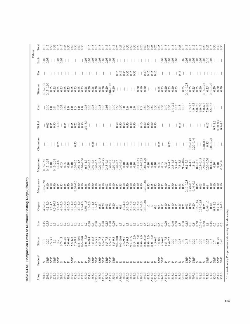
6-53
Table 6.4.5a
Composition Limits of Aluminum Casting Alloys (Percent)
Others
Alloy
Product*
Silicon
Iron
Copper
Manganese
Magnesium
Chromium
Nickel
Zinc
Titanium
Tin
Each
Total
201.0
S0.10
0.15
4.0–5.2
0.20–0.50
0.15–0.55
——
—0.15–0.35
—0.05
0.10
204.0
S&P
0.20
0.35
4.2–5.0
0.10
0.15–0.35
—0.05
0.10
0.15–0.30
—0.05
0.15
208.0
S&P
2.5–3.5
1.2
3.5–4.5
0.50
0.10
—0.35
1.0
0.25
——
0.50
222.0
S&P
2.0
1.5
9.2–10.7
0.50
0.15–0.35
—0.50
0.8
0.25
——
0.35
242.0
S&P
0.7
1.0
3.5–4.5
0.35
1.2–1.8
0.25
1.7–2.3
0.35
0.25
—0.05
0.15
295.0
S0.7–1.5
1.0
4.0–5.0
0.35
0.03
——
0.35
0.25
—0.05
0.15
296.0
P2.0–3.0
1.2
4.0–5.0
0.35
0.05
—0.35
0.50
0.25
——
0.35
308.0
P5.0–6.0
1.0
4.0–5.0
0.50
0.10
——
1.0
0.25
——
0.50
319.0
S&P
5.5–6.5
1.0
3.0–4.0
0.50
0.10
—0.35
1.0
0.25
——
0.50
328.0
S7.5–8.5
1.0
1.0–2.0
0.20–0.6
0.20–0.6
0.35
0.25
1.5
0.25
——
0.50
332.0
P8.5–10.5
1.2
2.0–4.0
0.50
0.50–1.5
—0.50
1.0
0.25
——
0.50
333.0
P8.0–10.0
1.0
3.0–4.0
0.50
0.05–0.50
—0.50
1.0
0.25
——
0.50
336.0
P11.0–13.0
1.2
0.50–1.5
0.35
0.7–1.3
—2.0–3.0
0.35
0.25
—0.05
—354.0
S&P
8.6–9.4
0.20
1.6–2.0
0.10
0.40–0.6
——
0.10
0.20
—0.05
0.15
355.0
S&P
4.5–5.5
0.6
1.0–1.5
0.50
0.40–0.6
0.25
—0.35
0.25
—0.05
0.15
C355.0
S&P
4.5–5.5
0.20
1.0–1.5
0.10
0.40–0.6
——
0.10
0.20
—0.05
0.15
356.0
S&P
6.5–7.5
0.6
0.25
0.35
0.20–0.45
——
0.35
0.25
—0.05
0.15
A356.0
S&P
6.5–7.5
0.20
0.20
0.10
0.25–0.45
——
0.10
0.20
—0.05
0.15
357.0
S&P
6.5–7.5
0.15
0.05
0.03
0.45–0.6
——
0.05
0.20
—0.05
0.15
A357.0
S&P
6.5–7.5
0.20
0.20
0.10
0.40–0.7
——
0.10
0.04–0.20
—0.05
0.15
359.0
S&P
8.5–9.5
0.20
0.20
0.10
0.50–0.7
——
0.10
0.20
—0.05
0.15
360.0
D9.0–10.0
2.0
0.6
0.35
0.40–0.6
—0.50
0.50
—0.15
—0.25
A360.0
D9.0–10.0
1.3
0.6
0.35
0.40–0.6
—0.50
0.50
—0.15
—0.25
380.0
D7.5–9.5
2.0
3.0–4.0
0.50
0.10
—0.50
3.0
—0.35
—0.50
A380.0
D7.5–9,5
1.3
3.0–4.0
0.50
0.10
—0.50
3.0
—0.35
—0.50
383.0
D9.5–11.5
1.3
2.0–3.0
0.50
0.10
—0.30
3.0
—0.15
—0.50
384.0
D10.5–12.0
1.3
3.0–4.5
0.50
0.10
—0.50
3.0
—0.35
—0.50
390.0
D16.0–18.0
1.3
4.0–5.0
0.10
0.45–0.65
——
0.10
0.20
——
0.20
B390.0
D16.0–18.0
1.3
4.0–5.0
0.50
0.45–0.65
—0.10
1.5
0.10
——
0.20
392.0
D18.0–20.0
1.5
0.40–0.80
0.20–0.60
0.80–1.20
—0.50
0.50
0.20
0.30
—0.50
413.0
D11.0–13.0
2.0
1.0
0.35
0.10
—0.50
0.50
—0.15
—0.25
A413.0
D11.0–13.0
1.3
1.0
0.35
0.10
—0.50
0.50
—0.15
—0.25
C433.0
D4.5–6.0
2.0
0.6
0.35
0.10
—0.50
0.50
—0.15
—0.25
443.0
S&P
4.5–6.0
0.8
0.6
0.50
0.05
0.25
—0.50
0.25
——
0.35
B443.0
S&P
4.5–6.0
0.8
0.15
0.35
0.05
——
0.35
0.25
—0.05
0.15
A444.0
P6.5–7.5
0.20
0.10
0.10
0.05
——
0.10
0.20
—0.05
0.15
512.0
S1.4–2.2
0.6
0.35
0.8
3.5–4.5
0.25
—0.35
0.25
—0.05
0.15
513.0
P0.30
0.40
0.10
0.30
3.5–4.5
——
1.4–2.2
0.20
—0.05
0.15
514.0
S0.35
0.50
0.15
0.35
3.5–4.5
——
0.15
0.25
—0.05
0.15
518.0
D0.35
1.8
0.25
0.35
7.5–8,5
—0.15
0.15
—0.15
—0.25
520.0
S0.25
0.30
0.25
0.15
9.5–10.6
——
0.15
0.25
—0.05
0.15
535.0
S&P
0.15
0.15
0.05
0.10–0.25
6.2–7.5
——
—0.10–0.25
—0.05
0.15
705.0
S&P
0.20
0.8
0.20
0.40–0.6
1.4–1.8
0.20–0.40
—2.7–3.3
0.25
—0.05
0.15
707.0
S&P
0.20
0.8
0.20
0.40–0.6
1.8–2.4
0.20–0.40
—4.0–4.5
0.25
—0.05
0.15
710.0
S0.15
0.50
0.35–0.65
0.05
0.6–0.8
——
6.0–7.0
0.25
—0.05
0.15
711.0
P0.30
0.7–1.4
0.35–0.65
0.05
0.25–0.45
——
6.0–7.0
0.20
—0.05
0.15
712.0
S0.30
0.50
0.25
0.10
0.50–0.65
0.40–0.6
—5.0–6.5
0.15–0.25
—0.05
0.20
713.0
S&P
0.25
1.1
0.40–1.0
0.6
0.20–0.50
0.35
0.15
7.0–8.0
0.25
—0.10
0.25
771.0
S0.15
0.15
0.10
0.10
0.8–1.0
0.06–0.20
—6.5–7.5
0.10–0.20
—0.05
0.15
850.0
S&P
0.7
0.7
0.7–1.3
0.10
0.10
—0.7–1.3
—0.20
——
0.30
851.0
S&P
2.0–3.0
0.7
0.7–1.3
0.10
0.10
—0.30–0.7
—0.20
——
0.30
852.0
S&P
0.40
0.7
1.7–2.3
0.10
0.6–0.9
—0.9–1.5
—0.20
——
0.30
* S
sand casting, P
permanent mold casting, D
die casting.
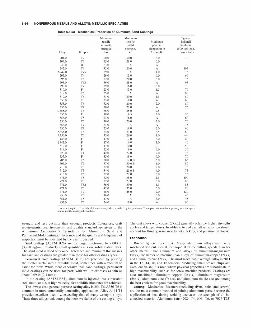
strength and less ductility than wrought products. Tolerances, draftrequirements, heat treatments, and quality standard are given in theAluminum Association’s “Standards for Aluminum Sand andPermanent Mold castings.” Tolerance and the quality and frequency ofinspection must be specified by the user if desired.
Sand castings (ASTM B26) are for larger parts—up to 7,000 lb(3,200 kg)—in relatively small quantities at slow solidification rates.The sand mold is used only once. Tolerance and minimum thicknessesfor sand and castings are greater than those for other castings types.
Permanent mold castings (ASTM B108) are produced by pouringthe molten metal into a reusable mold, sometimes with a vacuum toassist the flow. While more expensive than sand castings, permanentmold castings can be used for parts with wall thicknesses as thin asabout 0.09 in (2.3 mm).In die casting (ASTM B85), aluminum is injected into a reusable
steel mold, or die, at high velocity; fast solidification rates are achieved.The lowest-cost, general-purpose casting alloy is 356-T6; A356-T6 is
common in more structurally demanding applications. Alloy A444-T4provides excellent ductility, exceeding that of many wrought alloys.These three alloys rank among the most weldable of the casting alloys.
The cast alloys with copper (2xx.x) generally offer the higher strengthsat elevated temperatures. In addition to end use, alloys selection shouldaccount for fluidity, resistance to hot cracking, and pressure tightness.
Fabrication
Machining (see Sec. 13) Many aluminum alloys are easilymachined without special technique at faster cutting speeds than forother metals. Pure aluminum and alloys of aluminum-magnesium(5xxx) are harder to machine than alloys of aluminum-copper (2xxx)and aluminum-zinc (7xxx). The most machinable wrought alloy is 2011in the T3, T4, T6, and T8 tempers, producing small broken chips andexcellent finish; it is used where physical properties are subordinate tohigh machinability, such as for screw machine products. Castings arealso machined; aluminum-copper (2xx.x), aluminum-magnesium(5xx.x), aluminum-zinc (7xx.x), and aluminum-tin (8xx.x) are amongthe best choices for good machinability.Joining Mechanical fasteners (including rivets, bolts, and screws)
are the most common method of joining aluminum parts, because theapplication of heat during welding decreases the strength of all butannealed material. Aluminum bolts (2024-T4, 6061-T6, or 7075-T73)
6-54 NONFERROUS METALS AND ALLOYS; METALLIC SPECIALTIES
Table 6.4.5b Mechanical Properties of Aluminum Sand Castings
Minimum Minimum Typicaltensile tensile Minimum Brinnellultimate yield percent hardness strength, strength, elongation in (500-kgf load,
Alloy Temper ksi ksi 2 in or 4D 10-mm ball)
201.0 T7 60.0 50.0 3.0 —204.0 T4 45.0 28.0 6.0 —242.0 O 23.0 A A 70242.0 T61 32.0 20.0 A 105
A242.0 T75 29.0 A 1.0 75295.0 T4 29.0 13.0 6.0 60295.0 T6 32.0 20.0 3.0 75295.0 T62 36.0 28.0 A 95295.0 T7 29.0 16.0 3.0 70319.0 F 23.0 13.0 1.5 70319.0 T5 25.0 A A 80319.0 T6 31.0 20.0 1.5 80355.0 T51 25.0 18.0 A 65355.0 T6 32.0 20.0 2.0 80355.0 T71 30.0 22.0 A 75
C355.0 T6 36.0 25.0 2.5 —356.0 F 19.0 9.5 2.0 55356.0 T51 23.0 16.0 A 60356.0 T6 30.0 20.0 3.0 70356.0 T7 31.0 A A 75356.0 T71 25.0 18.0 3.0 60
A356.0 T6 34.0 24.0 3.5 80A356.0 T61 35.0 26.0 1.0 —443.0 F 17.0 7.0 3.0 40
B443.0 F 17.0 6.0 3.0 40512.0 F 17.0 10.0 — 50514.0 F 22.0 9.0 6.0 50520.0 T4 42.0 22.0 12.0 75535.0 F 35.0 18.0 9.0 70705.0 T5 30.0 17.0 B 5.0 65707.0 T7 37.0 30.0 B 1.0 80710.0 T5 32.0 20.0 2.0 75712.0 T5 34.0 25.0 B 4.0 75713.0 T5 32.0 22.0 3.0 75771.0 T5 42.0 38.0 1.5 100771.0 T51 32.0 27.0 3.0 85771.0 T52 36.0 30.0 1.5 85771.0 T6 42.0 35.0 5.0 90771.0 T71 48.0 45.0 2.0 120850.0 T5 16.0 A 5.0 45851.0 T5 17.0 A 3.0 45852.0 T5 24.0 18.0 A 60
A not required; B to be determined only when specified by the purchaser. These properties are for separately cast test spec-imens, not the castings themselves.

ALUMINUM AND ITS ALLOYS 6-55
are available in diameters from in (6.4 mm) to 1 in (25 mm), withproperties meeting ASTM F468. Mechanical properties are given inTable 6.4.6. Aluminum nuts (2024-T4, 6061-T6, or 6262-T9) are alsoavailable (ASTM F467). Galvanized steel and 300 series stainless steelbolts are also used to join aluminum. Hole diameter usually exceedsbolt diameter by in (1.6 mm) or less. Rivets are used to resist shearloads only; they do not develop sufficient clamping force between the
1⁄16
1⁄4 parts joined and so cannot reliably resist tensile loads. In general, rivetsof composition similar to the base metal are used; specialized aerospaceapplications sometimes use titanium and nickel alloy fasteners. Table 6.4.7lists common aluminum rivet alloys and their minimum ultimate shearstrengths. Hole diameter for cold-driven rivets should be no more than4 percent larger than the nominal rivet diameter. Screws of 2024-T4,7075-T73, or stainless steel are often used to fasten aluminum sheet.
Table 6.4.5c Mechanical Properties of Aluminum Permanent Mold Castings
Minimum Minimum Typicaltensile tensile Minimum Brinnellultimate yield percent hardnessstrength, strength, elongation in (500-kgf load,
Alloy Temper ksi ksi 2 in or 4D 10-mm ball)
204.0 T4 separately cast specimens 48.0 29.0 8.0 —242.0 T571 34.0 — — 105242.0 T61 40.0 — — 110319.0 F 27.0 14.0 2.5 95332.0 T5 31.0 — — 105333.0 F 28.0 — — 90333.0 T5 30.0 — — 100333.0 T6 35.0 — — 105333.0 T7 31.0 — — 90336.0 T551 31.0 — — 105336.0 T65 40.0 — — 125354.0 T61 separately cast specimens 48.0 37.0 3.0354.0 T61 castings, designated area 47.0 36.0 3.0354.0 T61 castings, no location designated 43.0 33.0 2.0354.0 T62 separately cast specimens 52.0 42.0 2.0354.0 T62 castings, designated area 50.0 42.0 2.0354.0 T62 castings, no location designated 43.0 33.0 2.0355.0 T51 27.0 — — 75355.0 T62 42.0 — — 105355.0 T7 36.0 — — 90355.0 T71 34.0 27.0 — 80
C355.0 T61 separately cast specimens 40.0 30.0 3.0 85–90C355.0 T61 castings, designated area 40.0 30.0 3.0C355.0 T61 castings, no location designated 37.0 30.0 1.0 85356.0 F 21.0 10.0 3.0356.0 T6 33.0 22.0 3.0 85356.0 T71 25.0 — 3.0 70
A356.0 T61 separately cast specimens 38.0 26.0 5.0 80–90A356.0 T61 castings, designated area 33.0 26.0 5.0A356.0 T61 castings, no location designated 28.0 26.0 3.0357.0 T6 45.0 — 3.0 —
A357.0 T61 separately cast specimens 45.0 36.0 3.0 100A357.0 T61 castings, designated area 46.0 36.0 3.0 —A357.0 T61 castings, no location designated 41.0 31.0 3.0 —359.0 T61 separately cast specimens 45.0 34.0 4.0 90359.0 T61 castings, designated area 45.0 34.0 4.0359.0 T61 castings, no location designated 40.0 30.0 3.0359.0 T62 separately cast specimens 47.0 38.0 3.0 100359.0 T62 castings, designated area 47.0 38.0 3.0359.0 T62 castings, no location designated 40.0 30.0 3.0443.0 F 21.0 7.0 2.0 45
B443.0 F 21.0 6.0 2.5 45A444.0 T4 separately cast specimens 20.0 — 20 —A444.0 T4 castings, designated area 20.0 — 20 —513.0 F 22.0 12.0 2.5 60535.0 F 35.0 18.0 8.0 —705.0 T1 or T5 37.0 17.0 10.0707.0 T1 42.0 25.0 4.0707.0 T7 45.0 35.0 3.0711.0 T1 28.0 18.0 7.0 70713.0 T1 or T5 32.0 22.0 4.0850.0 T5 18.0 — 8.0851.0 T5 17.0 — 3.0851.0 T6 18.0 — 8.0852.0 T5 27.0 — 3.0
A not required;B to be determined only when specified by the purchaser.When not stated otherwise, properties are for separately cast test specimens, not the castings themselves.
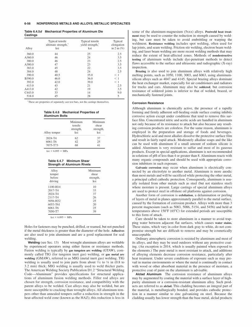
Holes for fasteners may be punched, drilled, or reamed, but not punchedif the metal thickness is greater than the diameter of the hole. Adhesives
are also used to join aluminum and are a good replacement for sealwelding.Welding (see Sec. 13) Most wrought aluminum alloys are weldable
by experienced operators using either fusion or resistance methods.Fusion welding is typically by gas tungsten arc welding (GTAW), com-monly called TIG (for tungsten inert gas) welding, or gas metal arc
welding (GMAW), referred to as MIG (metal inert gas) welding. TIGwelding is usually used to join parts from about to in (0.8 to3.2 mm) thick; MIG welding is usually used to weld thicker parts.The American Welding Society Publication D1.2 “Structural WeldingCode—Aluminum” provides specifications for structural applica-tions of aluminum fusion welding methods. Filler rod alloys arechosen for strength, corrosion resistance, and compatibility with theparent alloys to be welded. Cast alloys may also be welded, but aremore susceptible to cracking than wrought alloys. All aluminum tem-pers other than annealed tempers suffer a reduction in strength in theheat-affected weld zone (known as the HAZ); this reduction is less in
1⁄81⁄32
6-56 NONFERROUS METALS AND ALLOYS; METALLIC SPECIALTIES
Table 6.4.5d Mechanical Properties of Aluminum DieCastings
Typical tensile Typical tensile Typicalultimate strength,* yield strength,* elongation
Alloy ksi ksi in 2 in (%)
360.0 44 25 2.5A360.0 46 24 3.5380.0 46 23 2.5
A380.0 47 23 3.5383.0 45 22 3.5384.0 48 24 2.5390.0 40.5 35.0 ) 1B390.0 46.0 36.0 ) 1392.0 42.0 39.0 ) 1413.0 43 21 2.5
A413.0 42 19 3.5C443.0 33 14 9.0518.0 45 28 5
*These are properties of separately cast test bars, not the castings themselves.
Table 6.4.6 Mechanical Properties ofAluminum Bolts
Minimum Minimumtensile shearstrength, strength,
Alloy temper ksi ksi
2024-T4 62 376061-T6 42 257075-T73 68 41
ksi # 6.895 MPa
Table 6.4.7 Minimum ShearStrength of Aluminum Rivets
Alloy Minimumtemper shearbefore strength,driving ksi
1100-H14 102017-T4 332024-T4 372117-T4 265056-H32 256053-T61 206061-T6 257050-T7 39
ksi # 6.895 MPa
some of the aluminum-magnesium (5xxx) alloys. Postweld heat treat-
ment may be used to counter the reduction in strength caused by weld-ing, but care must be taken to avoid embrittling or warping theweldment. Resistance welding includes spot welding, often used forlap joints, and seam welding. Friction stir welding, electron beam weld-ing, and laser beam welding are more recent welding methods that mayreduce the extent of heat-affected zones. Methods of nondestructivetesting of aluminum welds include dye-penetrant methods to detectflaws accessible to the surface and ultrasonic and radiographic (X-ray)inspection.
Brazing is also used to join aluminum alloys with relatively highmelting points, such as 1050, 1100, 3003, and 6063, using aluminum-silicon alloys such as 4047 and 4145. Special brazing alloys dominatethe heat exchanger market, especially for air conditioners and radiatorsfor trucks and cars. Aluminum may also be soldered, but corrosionresistance of soldered joints is inferior to that of welded, brazed, ormechanically fastened joints.
Corrosion Resistance
Although aluminum is chemically active, the presence of a rapidlyforming and firmly adherent self-healing oxide surface coating inhibitscorrosive action except under conditions that tend to remove this sur-face film. Concentrated nitric and acetic acids are handled in aluminumnot only because of its resistance to attack but also because any result-ing corrosion products are colorless. For the same reason, aluminum isemployed in the preparation and storage of foods and beverages.Hydrochloric acid and most alkalies dissolve the protective surface filmand result in fairly rapid attack. Moderately alkaline soaps and the likecan be used with aluminum if a small amount of sodium silicate isadded. Aluminum is very resistant to sulfur and most of its gaseousproducts. Except in special applications, aluminum is not recommendedin solutions of pH of less than 4 or greater than 8. Aluminum reacts withmany organic compounds and should be used with appropriate corro-sion inhibitors in such exposure.
Galvanic corrosion may occur when aluminum is electrically con-nected by an electrolyte to another metal. Aluminum is more anodicthan most metals and will be sacrificed while protecting the other metal,a principal called cathodic protection. Consequently, aluminum is usu-ally isolated from other metals such as steel (but not stainless steel)where moisture is present. Large castings of special aluminum alloysare used to protect steel in offshore oil platforms against corrosion.Another form of corrosion is exfoliation, a delamination or peeling
of layers of metal in planes approximately parallel to the metal surface,caused by the formation of corrosion product. Alloys with more than 3percent magnesium (such as 5083, 5086, 5154, and 5456) and held attemperatures above for extended periods are susceptibleto this form of attack.Care should be taken to store aluminum in a manner to avoid trap-
ping water between adjacent flat surfaces, which causes water stains.
These stains, which vary in color from dark gray to white, do not com-promise strength but are difficult to remove and may be cosmeticallyunacceptable.Ordinary atmospheric corrosion is resisted by aluminum and most of
its alloys, and they may be used outdoors without any protective coat-ing. (An exception is 2014, which is usually painted when exposed tothe elements.) The pure metal is most resistant to attack, and additionsof alloying elements decrease corrosion resistance, particularly afterheat treatment. Under severe conditions of exposure such as may pre-vail in marine environments or where the metal is continually in contactwith wood or other absorbent material in the presence of moisture, aprotective coat of paint on the aluminum is advisable.Alclad Aluminum The corrosion resistance of aluminum alloys
may by augmented by coating the material with a surface layer of high-purity aluminum or a corrosion-resistant aluminum alloy. Such prod-ucts are referred to as alclad. This cladding becomes an integral part ofthe material, is metallurgically bonded, and provides cathodic protec-tion in a manner similar to zinc galvanizing on steel. Because thecladding usually has lower strength than the base metal, alclad products
1508F s658Cd

ALUMINUM AND ITS ALLOYS 6-57
have slightly lower strength than uncoated material. Cladding thicknessvaries from 1.5 to 10 percent. Products available clad are 3003 tube,5056 wire, and 2014, 2024, 2219, 3003, 3004, 6061, 7075, 7178, and7475 sheet and plate.
Finishes
Anodizing is used to improve the corrosion resistance and appearance ofaluminum and is achieved by making the parts to be treated the anodein an electrolytic bath such as sulfuric acid. This process produces atough, adherent coating of aluminum oxide, usually 0.4 mil (0.01 mm)thick or greater. “The Surface Treatment and Finishing of AluminumAlloys,” by P. G. Sheasby and R. Pinner, provides useful information onanodizing. Any welding should be performed before anodizing, andfiller alloys should be chosen judiciously for good anodized colormatch with the base alloy. The film is colorless on pure aluminum andtends to be gray or colored on alloys containing silicon, copper, or otherconstituents. To provide a consistent color appearance after anodizing,AQ (anodizing quality) grade may be specified in certain alloys. Whereappearance is the overriding concern, 5005 sheet and 6063 extrusionsare preferred for anodizing. If a colored finish is desired, the electrolyt-ically oxidized article may be treated with a dye solution. Care must betaken in selecting the dye when the part will be exposed to weather, fornot all have proven to be colorfast. Two-step electrolytic coloring, pro-duced by first clear anodizing and then electrolytically depositinganother metal oxide, can produce shades of bronze, burgundy, and blue.Anodized aluminum is used for lighting fixtures, automotive trim, cos-metic cases, and aluminum wheels.Painting It is important to properly prepare the surface prior to the
application of paint or lacquers. A thin anodic film makes an excellentpaint base; alternatively, the aluminum surface may be chemically treatedwith a dilute phosphoric acid solution. Abrasion blasting may be used
on parts thick enough to resist perforation or warping. Zinc chromate isfrequently used as a primer, especially for corrosive environments, oranother conversion coating or special primer may be used. Most paintsare baked on; this can affect the strength of the metal if the bake tem-perature is high enough or applied long enough to cause annealing.Sometimes the paint baking process is used as the artificial aging heattreatment. Aluminum sheet is available with factory-baked paint finish;minimum mechanical properties must be obtained from the supplier.High-, medium-, and low-gloss paint finishes are available and aredetermined in accordance with ASTM D523.
Porcelain enameled finishes are ceramic coatings fired to coat thesurface of aluminum. They are particularly useful for high-temperatureapplications such as appliances or cookware or for increased corrosionresistance to acids and alkalies.The Aluminum Association’s publication “Designation System for
Aluminum Finishes” describes mechanical, chemical, and anodicfinishes; “Care of Aluminum” describes aluminum finishes, cleaning,handling, storage, cleaners, and coatings.Aluminum Conductors On a weight basis, aluminum has twice
the electrical conductivity of copper; on a volume basis, the conduc-tivity of aluminum is about 62 percent that of copper. For electricalapplications, a special, high-purity grade of aluminum is often used(1350, also referred to as EC), or aluminum is alloyed to improvestrength with minimum sacrifice in conductivity. Table 6.4.8 listscommon conductor alloys and gives their strengths and conductivitiesin various forms and treatments. In power transmission lines, the nec-essary strength for long spans is obtained by stranding aluminum wiresabout a core wire of steel (ACSR) or a higher-strength aluminumalloy. Since many soils are corrosive and electrically conductive, alu-minum electrical cables are shrouded in nonpermeable coatings whenused underground.
Table 6.4.8 Aluminum Electrical Conductors
Tensile Tensileultimate yield Min. electricalstrength, strength, conductivity,
Product, alloy, temper (size) ksi* ksi* % IACS†
Drawing Stock (Rod)
1350-O (0.375- to 1.000-in diameter) 8.5–14.0 61.81350-H12, H22 (0.375- to 1.000-in diameter) 12.0–17.0 61.51350-H14, H24 (0.375- to 1.000-in diameter) 15.0–20.0 61.41350-H16, H26 (0.375- to 1.000-in diameter) 17.0–22.0 61.35005-O (0.375-in diameter) 14.0–20.0 54.35005-H12, H22 (0.375-in diameter) 17.0–23.0 54.05005-H14, H24 (0.375-in diameter) 20.0–26.0 53.95005-H16, H26 (0.375-in diameter) 24.0–30.0 53.88017-H12, H22 (0.375-in diameter) 16.0–22.0 58.08030-H12 (0.375-in diameter) 16.0–20.5 60.08176-H14 (0.375-in diameter) 16.0–20.0 59.0
Wire
1350-H19 (0.0801 to 0.0900 in diameter) 26.0–27.5 61.05005-H19 (0.0801 to 0.0900 in diameter) 37.0–39.0 53.56201-T81 (0.0612 to 0.1327 in diameter) 46.0–48.0 52.58176-H24 (0.0500 to 0.2040 in diameter) 15.0–17.0 61.0
Extrusions
1350-H111 (all) 8.5 min 3.5 min 61.06101-H111 (0.250 to 2.000 in) 12.0 min 8.0 min 59.06101-T6 (0.125 to 0.500 in) 29.0 min 25.0 min 55.06101-T61 (0.125 to 0.749 in) 20.0 min 15.0 min 57.06101-T61 (0.750 to 1.499 in) 18.0 min 11.0 min 57.06101-T61 (1.500 to 2.000 in) 15.0 min 8.0 min 57.0
Rolled Bar
1350-H12 (0.125 to 1.000 in) 12.0 min 8.0 min 61.0Sawed Plate
1350-H112 (0.125 to 0.499 in) 11.0 min 6.0 min 61.01350-H112 (0.500 to 1.000 in) 10.0 min 4.0 min 61.01350-H112 (1.001 to 1.500 in) 9.0 min 3.5 min 61.0
Sheet
1350-O (0.006 to 0.125 in) 8.0–14.0 61.8
*ksi # 6.895 MPa.† % IACS # 0.581 MS/m.

BEARING METALS
by Frank E. Goodwin
REFERENCES: Current edition of ASM “Metals Handbook.” Publications of thevarious metal producers. Trade association literature containing material proper-ties. Applicable current ASTM and SAE Standards.
Babbitt metal is a general term used for soft tin and lead-base alloyswhich are cast as bearing surfaces on steel, bronze, or cast-iron shells.Babbitts have excellent embeddability (ability to embed foreign parti-cles in itself) and conformability (ability to deform plastically to com-pensate for irregularities in bearing assembly) characteristics. Thesealloys may be run satisfactorily against a soft-steel shaft. The limita-tions of Babbitt alloys are the tendency to spread under high, steadyloads and to fatigue under high, fluctuating loads. These limitationsapply more particularly at higher temperatures; e.g., increase in tem-perature between 68 and 2128F (20 and 1008C) reduces the metal’sstrength by 50 percent. These limitations can be overcome by properlydesigning the thickness and rigidity of the backing material, properlychoosing the Babbitt alloy for good mechanical characteristics, andensuring a good bond between backing and bearing materials.The important tin- and lead-base (Babbitt) bearing alloys are listed in
Table 6.4.9. Alloys 1 and 15 have been used in internal-combustionengines, but the desire of automobile manufacturers to eliminate leadhas resulted in the substitution of aluminum-based alloys. Alloy 1 per-forms satisfactorily at low temperatures, but alloy 15, an arsenic alloy,provides superior performance at elevated temperatures by virtue of itsbetter high-temperature hardness, ability to support higher loads, andlonger fatigue life. Alloys 2 and 3 contain more antimony, are harder,and are less likely to pound out. Alloys 7 and 8 are lead-base Babbittswhich will function satisfactorily under moderate conditions of loadand speed. Alloy B has been used for diesel engine bearings. In gener-al, increasing the lead content in tin-based Babbitt provides higherhardness, greater ease of casting, but lower strength values.
Silver lined bearings have an excellent record in heavy-duty applica-tions in aircraft engines and diesels. For reciprocating engines, silverbearings normally consist of electrodeposited silver on a steel backingwith an overlay of 0.001 to 0.005 in of lead. An indium flash on top ofthe lead overlay is used to increase corrosion resistance of the material.
Aluminum and zinc alloys are used for high-load, low-speed applica-tions but have not replaced Babbits for equipment operating under asteady high-speed load. The Al 20 to 30, Sn 3 copper alloy is bonded toa steel bearing shell. The Al 6.25, Sn 1, Ni 1, copper alloy can be eitherused as-cast or bonded to a bearing shell. The Al 3 cadmium alloy withvarying amounts of Si, Cu, and Ni can also be used in either of thesetwo ways. The Zn 11, Al 1, Cu 0.02, magnesium (ZA-12) and Zn 27, Al 2,Cu 0.01 magnesium (ZA-27) alloys are used in cast form, especially incontinuous-cast hollow-bar form.Mention should be made of cast iron as a bearing material. The flake
graphite in cast iron develops a glazed surface which is useful at surfacespeeds up to 130 ft/min and at loads up to 150 lb/in2 approx. Because
of the poor conformability of cast iron, good alignment and freedomfrom dirt are essential.
Copper-base bearing alloys have a wide range of bearing propertiesthat fit them for many applications. Used alone or in combination withsteel, Babbitt (white metal), and graphite, the bronzes and copper-leadsmeet the conditions of load and speed given in Table 6.4.10. Copper-lead
alloys are cast onto steel backing strips in very thin layers (0.02 in) toprovide bearing surfaces. Lead-based bearing alloys are still used indiesel engines; no lead-free alloy can withstand diesel firing loads.Three families of copper alloys are used for bearing and wear-resis-
tant alloys in cast form: phosphor bronzes (Cu-Sn), Cu-Sn-Pb alloys, andmanganese bronze, aluminum bronze, and silicon bronze. Typical compo-sitions and applications are listed in Table 6.4.10. Phosphor bronzeshave residual phosphorus ranging from 0.1 to 1 percent. Hardnessincreases with phosphorus content. Cu-Sn-Pb alloys have high resis-tance to wear, high hardness, and moderate strength. The high leadcompositions are well suited for applications where lubricant may bedeficient. The Mn, Al, and Si bronzes have high tensile strength, highhardness, and good resistance to shock. They are suitable for a widerange of bearing applications.
Porous bearing materials are used in light- and medium-duty applica-tions as small-sized bearings and bushings. Since they can operate forlong periods without an additional supply of lubricant, such bearings areuseful in inaccessible or inconvenient places where lubrication wouldbe difficult. Porous bearings are made by pressing mixtures of copperand tin (bronze), and often graphite, Teflon, or iron and graphite, andsintering these in a reducing atmosphere without melting. Iron-based,oil-impregnated sintered bearings are often used. By controlling theconditions under which the bearings are made, porosity may be adjustedso that interconnecting voids of up to 35 percent of the total volume maybe available for impregnation by lubricants. Applicable specificationsfor these bearings are given in Tables 6.4.11 and 6.4.12.Miscellaneous A great variety of materials, e.g., rubber, wood,
phenolic, carbon-graphite, ceramets, ceramics, and plastics, are in usefor special applications. Carbon-graphite is used where contaminationby oil or grease lubricants is undesirable (e.g., textile machinery, phar-maceutical equipment, milk and food processing) and for elevated-temperature applications. Composite bushings of carbon graphite withmetals, including copper and iron, are capable of service temperaturesup to 1,0008F (5378C). Notable among plastic materials are Teflon andnylon, the polycarbonate Lexan, and the acetal Delrin. Since Lexan andDelrin can be injection-molded easily, bearings can be formed quiteeconomically from these materials.
CEMENTED CARBIDES
by Don Graham
REFERENCES: Schwartzkopf and Kieffer, “Refractory Hard Metals,” Macmillan.German, “Powder Metallurgy Science,” 2d ed., Metal Powder IndustriesFederation. “Powder Metallurgy Design Manual,” 2d ed., Metal PowderIndustries Federation, Princeton, NJ. Goetzal, “Treatise on Powder Metallurgy,”
6-58 NONFERROUS METALS AND ALLOYS; METALLIC SPECIALTIES
Table 6.4.9 Compositions and Properties of Some Babbitt Alloys
Compressiveultimate strength Brinell hardness
ASTM B23-00Composition, %
688F, 208C, 688F 2128Fgrade Sn Sb Pb Cu As lb/in2 MPa (208C) (1008C)
1 91.0 4.5 0.35 4.5 — 12.9 88.6 17 82 89.0 7.5 0.35 3.5 — 14.9 103 24.5 123 84.0 8.0 0.35 8.0 — 17.6 121 27.0 14.57 10.0 15.0 74.5 0.5 0.45 15.7 108 22.5 10.58 5.0 15.0 79.5 0.5 0.45 15.6 108 20.0 9.515 1.0 16.0 82.5 0.5 1.10 — — 21.0 13.0
Other alloysB 0.8 12.5 83.3 0.1 3.05 — —ASTM B102, alloy Py 1815A 65 15 18 2 0.15 15 103 23 10
SOURCE: ASTM, reprinted with permission.

CEMENTED CARBIDES 6-59
Interscience. Schwartzkopf, “Powder Metallurgy,” Macmillan. Davis (ed.), ToolMaterials, “ASM Specialty Handbook,” ASM, Metals Park, OH, 1995. Grahamand Hale, Coated Cutting Tools, Carbide and Tool J., May–June 1982, p. 34.Graham, Trends in Coatings to the Year 2000, “Cutting Tool TechnologyConference Proceedings,” SME, 1997.
Cemented carbides are a commercially and technically important classof composite material. Comprised primarily of hard tungsten carbide(WC) grains cemented together with a cobalt (Co) binder, they can con-tain major alloying additions of titanium carbide (TiC), titanium car-bonitride (TiCN), tantalum carbide (TaC), niobium carbide (NbC),chromium carbide (CrC), etc., and minor additions of other elements.Because of the extremely high hardness, stiffness, and wear resistanceof these materials, their primary use is in cutting tools for the material
(usually metal, wood, composite, or rock) removal industry. Secondaryapplications are as varied as pen balls, food processing equipment, fuelpumps, wear surfaces, fishing line guide rings, large high-pressurecomponents, and even wedding rings. Since their introduction in themid-1920s, a very large variety of grades of carbides has been devel-oped and put into use in a diverse number of applications. They areubiquitous throughout industry, particularly so in the high-productionmetalworking sector.Most cemented carbide parts are produced by powder metallurgical
processes. Powders of WC, Co, and sometimes TiC and TaC combinedwith NbC are blended by either ball or attritor milling. The mixedpowder is then compacted under very high pressure in appropriatelyshaped molds. Pressed parts are sintered at temperatures between 1,250and 1,5008C, depending on the composition of the powder. During the
Table 6.4.11 Oil-lmpregnated Iron-Base Sintered Bearings (ASTM Standard B439-83)
Composition, %
Element Grade 1 Grade 2 Grade 3 Grade 4
Copper 7.0–11.0 18.0–22.0Iron 96.25 min 95.9 min Remainder* Remainder*Total other elements by 3.0 3.0 3.0 3.0difference, maxCombined carbon† (on basis 0.25 max 0.25–0.60 — —of iron only)Silicon, max 0.3 0.3 — —Aluminum, max 0.2 0.2 — —
* Total of iron plus copper shall be 97% min.† The combined carbon may be a metallographic estimate of the carbon in the iron.SOURCE: ASTM, reprinted with permission.
Table 6.4.12 Oil-lmpregnated Sintered Bronze Bearings (ASTM Standard B438-83)
Composition, %
Grade 1 Grade 2
Element Class A Class B Class A Class B
Copper 87.5–90.5 87.5–90.5 82.6–88.5 82.6–88.5Tin 9.5–10.5 9.5–10.5 9.5–10.5 9.5–10.5Graphite, max 0.1 1.75 0.1 1.75Lead * * 2.0–4.0 2.0–4.0Iron, max 1.0 1.0 1.0 1.0Total other elements by 0.5 0.5 1.0 1.0difference, max
* Included in other elements.SOURCE: ASTM, reprinted with permission.
Table 6.4.10 Compositions, Properties, and Applications of Some Copper-Base Bearing Metals
MinimumComposition, % tensile strength
Specifications Cu Sn Pb Zn P Other ksi MPa Applications
C86100, SAE J462 64 — — 24 — 3 Fe, 5 Al, 4 Mn 119 820 Extra-heavy-duty bearingsC87610, ASTM B30 90 — 0.2 5 — 4 Si 66 455 High-strength hearingsC90700, ASTM B505 89 11 0.3 — 0.2 — 44 305 Wormgears and wheels; high-speed
low-load bearingsC91100 84 16 — — — — 35 240 Heavy load, low-speed bearingsC91300 81 19 — — — — 35 240 Heavy load, low-speed bearingsC93200, SAE J462 83 7 7 3 — — 35 240 General utility bearings, automobile
fittingsC93700, ASTM B22 80 10 10 — — — 35 240 High-speed, high-pressure bearings,
good corrosion resistantC93800, ASTM B534 78 7 15 — — — 30 205 General utility bearings, backing for
Babbit bearingsC94300, ASTM B584 70 5 25 — — — 27 185 Low-load, high-speed bearings
SOURCE: ASTM, reprinted with permisstion.

sintering process, cobalt melts and wets the carbide particles. On cool-ing, cobalt “cements” the carbide grains together. Essentially completedensification takes place during sintering. A unique feature of cement-ed carbides is the fact that, although the part shrinks by as much as 40percent by volume when the porosity is eliminated by the moltencobalt, the pressed part retains its geometric shape very accurately. Thisis an important feature since further shaping of this extremely hardmaterial can be done accurately only by grinding with diamond wheelsor electrodischarge machining. Lasers can be used to cut cemented car-bide but not to tight tolerances. While binder metals such as iron ornickel are sometimes used, cobalt is preferred because of its ability towet the tungsten carbide.The metal removal industry consumes most of the cemented carbide
that is produced. Tips having unique geometries, called inserts, arepressed and sintered. Many of these pressed and sintered parts are readyfor use directly after sintering. Others are finish-ground either toimprove flatness on the seating surface or to produce very tight dimen-sional tolerances. Although the cutting edges on some inserts are left inthe sharp condition, most are honed slightly to improve chippage resis-tance and reliability. Sharp edges typically are used for machining suchmaterials as nonferrous metals and alloys, high-temperature alloys,alloys used for medical components (e.g., hip and knee replacementparts) and nonmetals. Honed inserts are used for all other applications,including those in the commercially important iron and steels industries.The first cemented carbides developed consisted only of WC and Co.
As cutting speeds were increased to take advantage of the high hardnessof this material, temperatures at the tool/workpiece interface increased.In the presence of iron or steel at high temperatures, carbide tools inter-act chemically with the work materials and result in cratering, which,somewhat simplistically, is the dissolution of WC at the cutting edge.This results in a dimple on the surface of the insert that resembles acrater. Additions of secondary carbides such as TiC and TaC mini-mize cratering—and thereby improve tool life—by virtue of theirgreater chemical stability. Grades containing these secondary carbideswere introduced during the 1940s and were able to machine steel atspeeds up to 600 surface feet per minute (sfpm).With the ever-increasing desire for even greater metal removal rates,
higher cutting speeds (and accompanying higher temperatures) wereused. Chemical vapor deposition (CVD) overlay coatings were developedwhich were far more effective at preventing cratering than TiC and TaCadditions to the carbide. These hard coatings have the additional bene-fit of increased abrasion resistance.Titanium carbide coatings became available in 1969; titanium nitride
(TiN) coatings followed shortly, Aluminum oxide (Al2O3) coatings foreven higher-speed applications were introduced in 1973. Today the largemajority of coated carbide grades incorporate all three materials in dis-tinct layers. Over the years dramatic improvements in deposition tech-niques and structural control have led to equally dramatic improvementsin performance. Coatings typically result in tool life increases of at least50 percent although 10-fold improvements are common. Extreme casesof 10,000 percent tool life improvements over uncoated carbide havebeen reported.Each coating composition has its own specific advantages. For exam-
ple, TiC and TiCN are very hard at lower temperatures and are ideal forvery abrasive applications. Hence carbide grades designed for machin-ing ductile irons, austemperated ductile iron, compacted graphite iron,malleable iron, alloy steels, etc. incorporate relatively thick layers ofthese coatings.TiN, along with other commercially available nitride coatings such as
hafnium nitride (HfN) and zirconium nitride (ZrN), exhibits excellentmetal buildup resistance. This feature is particularly important whenmachining softer, gummy alloys such as stainless steel, low-carbon steel,and many high-temperature alloys. Metal buildup occurs when frag-ments of the work material become welded to the cutting edge. Thischange in the geometry of the cutting edge results in a poor surface fin-ish and, eventually, chippage of the cutting edge. Since metal buildup isparticularly problematic at low cutting speeds, grades designed forlower speeds almost always feature this coating. Even grades designed
for higher speeds often use TiN for a top coat, not only to prevent metalbuildup but also, because it is gold in color, to allow for easy determi-nation of which insert edges have been used. Such detection is more dif-ficult if the insert is black.Aluminum oxide is very stable chemically and retains its hardness at
elevated temperatures. Consequently, this coating is especially effective atelevated speeds. Grades designed for high-productivity ferrous applica-tions almost always feature a thick layer of Al2O3. Although clear, Al2O3appears black due to the adhesive that bonds this coating to the substrateor underlying coating layers.Another commercially important coating technique is physical vapor
deposition (PVD). For certain applications, this coating technique pro-vides certain advantages over the CVD technique. First, PVD coatingsare thinner and therefore replicate the cutting edge condition moreaccurately. This means that very sharp edges can be preserved withthese coatings. Second, there is no loss in strength associated with thedeposition of a PVD coating. The presence of a CVD coating, bycomparison, usually reduces the edge toughness of a carbide insert byabout 10 percent. As a consequence, PVD coated carbides are usedmost often for the turning of high-temperature alloys, stainless steelsat low to medium cutting speeds, and for a wide variety of drilling,threading, and even milling of a broad range of materials. PVD coat-ed carbide is also used in a number of mold, die, punch, and wearresistance applications.The primary disadvantage of PVD coatings is their lack of thickness
and consequent low wear and crater resistance. Typical CVD coatedinserts have coating thicknesses ranging from 10 to 20 mm; PVD coat-ings are usually 2.5 to 4 mm thick.The most common PVD coatings are TiN, titanium aluminum nitride
(TiAlN), and TiCN. Of these, TiAlN is the hardest and most stable anduseful at relatively high speeds (although not as high as CVD coatingsallow). Other coatings that can be obtained include ZrN, CrN, and variouscarbon coatings. The PVD field is very dynamic; improved versions of thelisted coatings as well as brand new coatings are always being introduced.
Design Considerations
Cemented carbide, in common with all brittle materials, may fragmentin service, particularly under conditions of impact or upon release fromhigh compressive loading. Additionally, if other failure modes—chipping, cratering, deformation, wear, thermal cracking—encounteredduring use are allowed to progress too far, fracture can occur.Precautionary measures must be taken to ensure that personnel andequipment are protected from flying fragments and sharp edges whenworking with brittle tools.Failure of brittle materials frequently occurs as a result of tensile
stress at or near the surface; thus the strength of brittle materials is verydependent on surface conditions. Chips, scratches, thermal cracks, andgrinding marks, which decrease the strength and breakage resistance ofcemented carbide parts, should be avoided. Even electric-dischargemachined (EDM) surfaces should be ground or lapped to a depth of0.05 mm to remove damaged material.Special care must be taken when one is grinding cemented carbides.
Adequate ventilation of grinding spaces must comply with existinggovernment regulations applicable to the health and safety of the work-place environment. During the fabrication of cemented carbide parts,particularly during grinding of tools and components, adequate provi-sions must be made for the removal and collection of generated dustsand cutting fluid mists that contain microscopic metal particles, eventhough those concentrations may be very low. Although the elementscontained in these alloys are not radioactive, note that they may becomeradioactive when exposed to a sufficiently strong radiation source. Thecobalt in the cemented carbide alloys, in particular, could be maderadioactive.
Physical and Mechanical Properties
Typical property data are shown in Table 6.4.13. In addition to beingan effective “cement,” cobalt is the primary component that deter-mines mechanical properties. For example, as cobalt content increases,
6-60 NONFERROUS METALS AND ALLOYS; METALLIC SPECIALTIES

6-61
Table 6.4.13
Properties of Cemented Carbides
Abrasion
Transverse
Ultimate
Ultimate
Modulus
Thermal
Grain
resistance,
rupture
compressive
tensile
of
Proportional
Fracture
expansion
Thermal
Electrical
Composition,
size,
Hardness,
I/vol. loss
Density,
strength,
strength,
strength,
elasticity,
limit,
Ductility,
toughness,
75 to 4008F,
conductivity,
resistivity,
wt. %
mm
Ra
cm3
g/cm3
1,000 lb/in2
1,000 lb/in2
1,000 lb/in2
106lb/in2
1,000 lb/in2
% elong
(lb/in2)(
)in/(in "
8F)#10%6
cal/(s"8C"cm)
m&"cm
WC-3% Co
1.7
93
60
15.3
290
850
98
350
2.2
0.3
17
WC-6% Co
0.8
93.5
62
15
WC-6% Co
1.1
92.8
60
15
335
860
160
92
370
0.2
2.9
WC-6% Co
2.1
92
35
15
380
790
92
280
9,200
2.5
0.25
17
WC-6% Co
391
15
15
400
750
220
92
210
11,500
2.4
0.25
17
WC-9% Co
489.5
10
14.7
425
660
87
140
13,000
2.7
0.25
WC-10% Co
1.8
91
13
14.6
440
750
85
230
11,500
WC-10% Co
5.2
89
714.5
460
630
85
130
2.5
17
WC-13% Co
488.2
414.2
500
600
81
140
0.3
14,500
30.25
17
WC-16% Co
486.8
313.9
500
560
270
77
100
0.4
15,800
3.2
0.02
WC-25% Co
3.7
84
213
440
450
67
60
21,000
3.5
0.2
18
Other materials*
Tool steel (T-g)
85 (66 R
c)2
8.4
575
600
34
6.5
Carbon steel (1095)
79 (55 R
c)7.8
300
30
0.12
20
Cast iron
7.3
105
15–30
Copper
8.9
9.2
0.94
1.67
*Data for other materials are included to aid in comparing carbide properties with those of referenced materials.
2in

toughness increases but hardness and wear resistance decrease. Thistradeoff is illustrated in Table 6.4.13. A secondary factor that affectsmechanical properties is WC grain size. Finer grain size leads toincreased hardness and wear resistance but lower toughness.Micrograin Carbides An important segment of the cemented
carbides is micrograin carbide. As the name implies, these gradesfeature grains that are less than 1 mm in diameter. As the carbide grainsize decreases, hardness increases but toughness decreases. However,once the WC grain size diameter drops below approximately 1 mm,this trade-off becomes much more favorable. Further decreases ingrain size result in continued increases in hardness but are accompa-nied by a much smaller drop in toughness. As a result, micrograin
cemented carbides have outstanding hardness, wear resistance, andcompressive strength combined with surprising toughness relative toconventional carbides. This combination of properties makes thesegrades particularly useful in machining nickel-, cobalt-, and iron-based superalloys and other difficult to machine alloys, such asrefractories and titanium alloys. They also find favor machining non-ferrous materials.Mechanical Properties The outstanding features of cemented car-
bides are their hardness, high compressive strength, stiffness, and wearresistance. Unfortunately, but as might be expected of hard materials,the toughness and ductility of carbides are low. Table 6.4.13 lists somemechanical and physical property data for typical and popular cementedcarbide compositions.Hardness and Wear Resistance Most applications of cemented
carbide alloys involve wear and abrasive conditions. In general, thewear resistance of these materials can be estimated based on hardness.Note that wear is a complex process and can occur by means other thannormal abrasion. Should wear occur by microchipping, fracture, chem-ical attack, or metallurgical interactions, it will be obvious that perfor-mance does not correlate directly with hardness.The data presented in Table 6.4.13 under the heading Abrasion
Resistance were determined by using an abrasive wheel. Results fromthis simplified test should be used only as a rough guide in the selectionof those alloys, since abrasive wear that occurs under actual serviceconditions is usually complex and varies greatly with particular cir-cumstances. The performance characteristics of a given grade are,of course, best determined under actual service conditions.In many applications, cemented carbides are subjected to relatively
high operating temperatures. For example, the temperatures of the inter-face between the chip and the cutting edge of a carbide cutting tool mayreach between 500 and 1,1008C. Wear parts may have point contacttemperatures in this range. The extent to which the cemented carbidemaintains its hardness at the elevated temperatures encountered inuse is an important consideration. The cemented carbides not only havehigh room-temperature hardness, but also maintain hardness at elevat-ed temperatures better than do steels and cast alloys. Corrosion Resistance The corrosion resistance of the various
cemented carbide alloys is fairly good when compared with other mate-rials, and they may be employed very advantageously in some corrosiveenvironments where outstanding wear resistance is required. Generallythey are not employed where corrosion resistance alone is the require-ment because other materials usually can be found which are eithercheaper or more corrosion-resistant.Corrosion may cause strength deterioration due to the preferential
attack on the binder matrix phase. This results in the creation of micro-scopic surface defects to which cemented carbides, in common withother brittle materials, are sensitive.Special corrosion-resistant grades have been developed in which the
cobalt binder has been modified or replaced by other metals or alloys,resulting in improved resistance to acid attack. Usually these gradesfeature a nickel (Ni) binder, perhaps alloyed with small amounts ofchromium (Cr). Other factors such as temperature, pressure, and sur-face condition may significantly influence corrosive behavior, so that spe-cific tests under actual operating conditions should be performed whenpossible to select a cemented carbide grade for service under corrosiveconditions.
Cermets
Another class of composite material that fits in this general category iscermet. These alloys are more complex in terms of both their chemistryand their structure, but usually consist of TiCN or TiC grains and a nickel(Ni) or nickel-molybdenum (Ni-Mo) alloy binder. Other alloying ele-ments such as Co and W are usually present. Cermets usually findapplication in the high-speed finish machining of steels, stainless steels,and occasionally cast irons and high-temperature alloys. They are alsovery useful for machining powder metallurgical materials. As a rule,cermets provide better surface finishes and are more wear-resistant butless tough than traditional cemented tungsten carbides. Recent process-ing improvements, such as sinter HIP (hot isostatic pressing) and a bet-ter understanding of the alloying characteristics of cermets, have helpedbetter their toughness immensely, so that cermets tough enough formilling are now available.
COPPER AND COPPER ALLOYS
by Arthur Cohen
REFERENCES: ASM “Metals Handbook,” Applicable current ASTM and SAEStandards. Publications of the Copper Development Association Standards pro-mulgated by industrial associations related to specific types of products.
Copper and copper alloys constitute one of the major groups of com-mercial metals. They are widely used because of their excellent electri-cal and thermal conductivities, outstanding corrosion resistance, andease of fabrication. They are generally nonmagnetic and can be readilyjoined by conventional soldering, brazing, and welding processes (gasand resistance).
Primary Copper
Copper used in the manufacture of fabricated brass mill or wire andcable products may originate in the ore body of open-pit or undergroundmines or from rigidly controlled recycled high-grade copper scrap.Traditional sulfide ores require conventional crushing, milling, con-
centration by flotation, smelting to form a matte, conversion to blistercopper, and final refining by either the electrolytic or the electrowinning
processes to produce copper cathode, which is fully described in ASTMB115 Electrolytic Cathode Copper. This electrochemical refining stepresults in the deposition of virtually pure copper, with the major impu-rity being oxygen.Probably the single most important innovation in the copper industry
in the past 30 years has been the introduction of continuous cast wire rod
technology. Within this period, the traditional 250-lb wire bar has beenalmost completely replaced domestically (and largely internationally) withcontinuous cast wire rod product produced to meet the requirements ofASTM B49 Copper Redraw Rod for Electrical Purposes.
Generic Classification of Copper Alloys
The most common way to categorize wrought and cast copper and cop-per alloys is to divide them into six families: coppers, high-copperalloys, brasses, bronzes, copper nickels, and nickel silvers. They arefurther subdivided and identified via the Unified Numbering System
(UNS) for metals and alloys.The designation system is an orderly method of defining and identi-
fying the alloys. The copper section is administered by the CopperDevelopment Association, but it is not a specification. It eliminates thelimitations and conflicts of alloy designations previously used and atthe same time provides a workable method for the identification mark-ing of mill and foundry products.In the designation system, numbers from C10000 through C79999
denote wrought alloys. Cast alloys are numbered from C80000 throughC999999. Within these two categories, compositions are further groupedinto families of coppers and copper alloys shown in Table 6.4.14.Coppers These metals have a designated minimum copper content
of 99.3 percent or higher.High-Copper Alloys In wrought form, these are alloys with desig-
nated copper contents less than 99.3 percent but more than 96 percent
6-62 NONFERROUS METALS AND ALLOYS; METALLIC SPECIALTIES

COPPER AND COPPER ALLOYS 6-63
which do not fall into any other copper alloy group. The cast high-copper alloys have designated copper contents in excess of 94 percent,to which silver may be added for special properties.Brasses These alloys contain zinc as the principal alloying ele-
ment with or without other designated alloying elements such as iron,aluminum, nickel, and silicon. The wrought alloys comprise three mainfamilies of brasses: copper-zinc alloys; copper-zinc-lead alloys (leadedbrasses); and copper-zinc-tin alloys (tin brasses). The cast alloys com-prise four main families of brasses: copper-tin-zinc alloys (red, semired,and yellow brasses); manganese bronze alloys (high-strength yellowbrasses); leaded manganese bronze alloys (leaded high-strength yellowbrasses); and copper-zinc-silicon alloys (silicon brasses and bronzes).Ingot for remelting for the manufacture of castings may vary slightlyfrom the ranges shown.Bronzes Broadly speaking, bronzes are copper alloys in which the
major element is not zinc or nickel. Originally bronze described alloyswith tin as the only or principal alloying element. Today, the term gen-erally is used not by itself, but with a modifying adjective. For wroughtalloys, there are four main families of bronzes: copper-tinphosphorusalloys (phosphor bronzes); copper-tin-lead-phosphorus alloys (leadedphosphor bronzes); copper-aluminum alloys (aluminum bronzes); andcopper-silicon alloys (silicon bronzes).The cast alloys comprise four main families of bronzes: copper-tin
alloys (tin bronzes); copper-tin-lead alloys (leaded and high leaded tinbronzes); copper-tin-nickel alloys (nickel-tin bronzes); and copper-aluminum alloys (aluminum bronzes).The family of alloys known as manganese bronzes, in which zinc is the
major alloying element, is included in the brasses.Copper-Nickels These are alloys with nickel as the principal alloy-
ing element, with or without other designated alloying elements.Copper-Nickel-Zinc Alloys Known commonly as nickel silvers, these
are alloys which contain zinc and nickel as the principal and secondaryalloying elements, with or without other designated elements.Leaded Coppers These comprise a series of cast alloys of copper
with 20 percent or more lead, sometimes with a small amount of silver,but without tin or zinc.
Miscellaneous Alloys Alloys whose chemical compositions do notfall into any of previously described categories are combined under“miscellaneous alloys.”
Temper Designations
Temper designations for wrought copper and copper alloys were origi-nally specified on the basis of cold reduction imparted by the rolling ofsheet or drawing of wire. Designations for rod, seamless tube, weldedtube, extrusions, castings and heat-treated products were not covered. In1974, ASTM B601 Standard Practice for Temper Designations forCopper and Copper Alloys—Wrought and Cast, based on an alphanu-meric code, was created to accommodate this deficiency. The generaltemper designation codes listed in ASTM B601 by process and productare shown in Table 6.4.15.
Coppers
Coppers include the oxygen-free coppers (C10100 and C10200), madeby melting prime-quality cathode copper under nonoxidizing condi-tions. These coppers are particularly suitable for applications requiringhigh electrical and thermal conductivities coupled with exceptionalductility and freedom from hydrogen embrittlement.The most common copper is C11000—electrolytic tough pitch. Its
electrical conductivity exceeds 100 percent IACS and is invariablyselected for most wire and cable applications. Selective properties ofwire produced to ASTM B1 Hard Drawn Copper Wire, B2 MediumHard Drawn Copper Wire, and B3 Soft or Annealed Copper Wire areshown in Table 6.4.16.Where resistance to softening along with improved fatigue strength
is required, small amounts of silver are added. This permits the silver-containing coppers to retain the effects of cold working to a higher tem-perature than pure copper (about 6008F versus about 4008F), a propertyparticularly useful where comparatively high temperatures are to bewithstood, as in soldering operations or for stressed conductors designedto operate at moderately elevated temperatures.If superior machinability is required, C14500 (tellurium copper),
C14700 (sulfur copper), or C18700 (leaded copper) can be selected.
Table 6.4.14 Generic Classification of Copper Alloys
Generic name UNS Nos. Composition
Wrought alloys
Coppers C10100–C15815 ' 99% CuHigh-copper alloys C16200–C19900 ' 96% CuBrasses C21000–C28000 Cu-ZnLeaded brasses C31200–C38500 Cu-Zn-PbTin brasses C40400–C48600 Cu-Zn-Sn-PbPhosphor bronzes C50100-C52400 Cu-Sn-PLeaded phosphor bronzes C53200–C54400 Cu-Sn-Pb-PCopper-phosphorus and copper-silver-phosphorus alloys C55180–C55284 Cu-P-AgAluminum bronzes C60800–C64210 Cu-Al-Ni-Fe-Si-SnSilicon bronzes C64700–C66100 Cu-Si-SnOther copper-zinc alloys C66400–C69710 —Copper nickels C70100–C72950 Cu-Ni-FeNickel silvers C73500–C79800 Cu-Ni-Zn
Cast alloys
Coppers C80100–C81200 ' 99% CuHigh-copper alloys C81400–C82800 ' 94% CuRed and leaded red brasses C83300–C84800 Cu-Zn-Sn-Pb (75–89% Cu)Yellow and leaded yellow brasses C85200–C85800 Cu-Zn-Sn-Pb (57–74% Cu)Manganese bronzes and leaded manganese bronzes C86100–C86800 Cu-Zn-Mn-Fe-PbSilicon bronzes, silicon brasses C87300–C87800 Cu-Zn-SiTin bronzes and leaded tin bronzes C90200–C94500 Cu-Sn-Zn-PbNickel-tin bronzes C94700–C94900 Cu-Ni-Sn-Zn-PbAluminum bronzes C95200–C95900 Cu-Al-Fe-NiCopper nickels C96200–C96900 Cu-Ni-FeNickel silvers C97300–C97800 Cu-Ni-Zn-Pb-SnLeaded coppers C98200–C98840 Cu-PbMiscellaneous alloys C99300–C99750 —
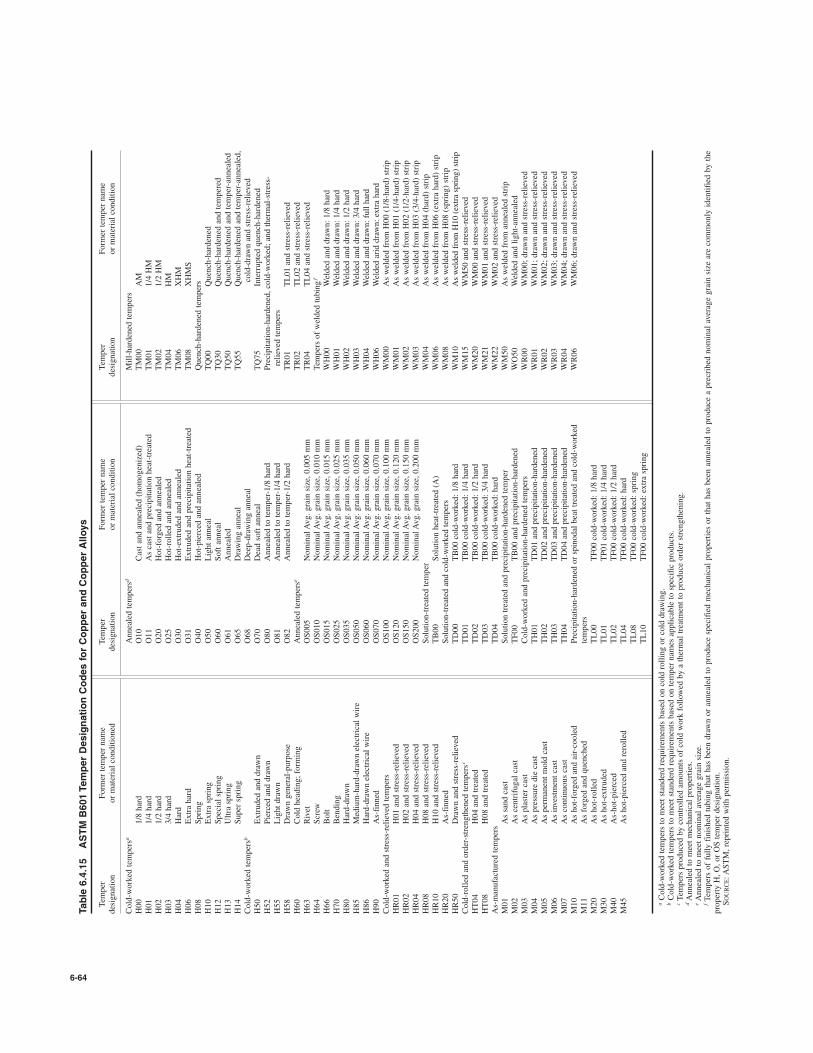
6-64
Table 6.4.15
ASTM B601 Temper Designation Codes for Copper and Copper Alloys
Temper
Former temper name
Temper
Former temper name
Temper
Former temper name
designation
or material conditioned
designation
or material condition
designation
or material condition
Cold-worked tempersa
Annealed tempersd
Mill-hardened tempers
H00
1/8 hard
O10
Cast and annealed (homogenized)
TM00
AM
H01
1/4 hard
O11
As cast and precipitation heat-treated
TM01
1/4 HM
H02
1/2 hard
O20
Hot-forged and annealed
TM02
1/2 HM
H03
3/4 hard
O25
Hot-rolled and annealed
TM04
HM
H04
Hard
O30
Hot-extruded and annealed
TM06
XHM
H06
Extra hard
O31
Extruded and precipitation heat-treated
TM08
XHMS
H08
Spring
O40
Hot-pierced and annealed
Quench-hardened tempers
H10
Extra spring
O50
Light anneal
TQ00
Quench-hardened
H12
Special spring
O60
Soft anneal
TQ30
Quench-hardened and tempered
H13
Ultra spring
O61
Annealed
TQ50
Quench-hardened and temper-annealed
H14
Super spring
O65
Drawing anneal
TQ55
Quench-hardened and temper-annealed,
Cold-worked tempersb
O68
Deep-drawing anneal
cold-drawn and stress-relieved
H50
Extruded and drawn
O70
Dead soft anneal
TQ75
Interrupted quench-hardened
H52
Pierced and drawn
O80
Annealed to temper-1/8 hard
Precipitation-hardened, cold-worked; and thermal-stress-
H55
Light drawn
O81
Annealed to temper-1/4 hard
relieved tempers
H58
Drawn general-purpose
O82
Annealed to temper-1/2 hard
TR01
TL01 and stress-relieved
H60
Cold heading; forming
Annealed temperse
TR02
TL02 and stress-relieved
H63
Rivet
OS005
Nominal Avg. grain size, 0.005 mm
TR04
TL04 and stress-relieved
H64
Screw
OS010
Nominal Avg. grain size, 0.010 mm
Tempers of welded tubingf
H66
Bolt
OS015
Nominal Avg. grain size, 0.015 mm
WH00
Welded and drawn: 1/8 hard
H70
Bending
OS025
Nominal Avg. grain size, 0.025 mm
WH01
Welded and drawn: 1/4 hard
H80
Hard-drawn
OS035
Nominal Avg. grain size, 0.035 mm
WH02
Welded and drawn: 1/2 hard
H85
Medium-hard-drawn electrical wire
OS050
Nominal Avg. grain size, 0.050 mm
WH03
Welded and drawn: 3/4 hard
H86
Hard-drawn electrical wire
OS060
Nominal Avg. grain size, 0.060 mm
WH04
Welded and drawn: full hard
H90
As-finned
OS070
Nominal Avg. grain size, 0.070 mm
WH06
Welded arid drawn: extra hard
Cold-worked and stress-relieved tempers
OS100
Nominal Avg, grain size, 0.100 mm
WM00
As welded from H00 (1/8-hard) strip
HR01
H01 and stress-relieved
OS120
Nominal Avg. grain size, 0.120 mm
WM01
As welded from H01 (1/4-hard) strip
HR02
H02 and stress-relieved
OS150
Nominal Avg. grain size, 0.150 mm
WM02
As welded from H02 (1/2-hard) strip
HR04
H04 and stress-relieved
OS200
Nominal Avg. grain size, 0.200 mm
WM03
As welded from H03 (3/4-hard) strip
HR08
H08 and stress-relieved
Solution-treated temper
WM04
As welded from H04 (hard) strip
HR10
H10 and stress-relieved
TB00
Solution heat-treated (A)
WM06
As welded from H06 (extra hard) strip
HR20
As-finned
Solution-treated and cold-worked tempers
WM08
As welded from H08 (spring) strip
HR50
Drawn and stress-relieved
TD00
TB00 cold-worked: 1/8 hard
WM10
As welded from H10 (extra spring) strip
Cold-rolled and order-strengthened tempersc
TD01
TB00 cold-worked: 1/4 hard
WM15
WM50 and stress-relieved
HT04
H04 and treated
TD02
TB00 cold-worked: 1/2 hard
WM20
WM00 and stress-relieved
HT08
H08 and treated
TD03
TB00 cold-worked: 3/4 hard
WM21
WM01 and stress-relieved
As-manufactured tempers
TD04
TB00 cold-worked: hard
WM22
WM02 and stress-relieved
M01
As sand cast
Solution treated and precipitation-hardened temper
WM50
As welded from annealed strip
M02
As centrifugal cast
TF00
TB00 and precipitation-hardened
WO50
Welded and light-annealed
M03
As plaster cast
Cold-worked and precipitation-hardened tempers
WR00
WM00; drawn and stress-relieved
M04
As pressure die cast
TH01
TD01 and precipitation-hardened
WR01
WM01; drawn and stress-relieved
M05
As permanent mold cast
TH02
TD02 and precipitation-hardened
WR02
WM02; drawn and stress-relieved
M06
As investment cast
TH03
TD03 and precipitation-hardened
WR03
WM03; drawn and stress-relieved
M07
As continuous cast
TH04
TD04 and precipitation-hardened
WR04
WM04; drawn and stress-relieved
M10
As hot-forged and air-cooled
Precipitation-hardened or spinodal beat treated and cold-worked
WR06
WM06; drawn and stress-relieved
M11
As forged and quenched
tempers
M20
As hot-rolled
TL00
TF00 cold-worked: 1/8 hard
M30
As hot-extruded
TL01
TP01 cold-worked: 1/4 hard
M40
As-hot-pierced
TL02
TF00 cold-worked: 1/2 hard
M45
As hot-pierced and rerolled
TL04
TF00 cold-worked: hard
TL08
TF00 cold-worked: spring
TL10
TF00 cold-worked: extra spring
aCold-worked tempers to meet standerd requirements based on cold rolling or cold drawing.
bCold-worked tempers to meet standerd requirements based on temper names applicable to specific products.
cTempers produced by controlled amounts of cold work followed by a thermal treatment to produce order strengthening.
dAnnealed to meet mechanical properties.
eAnnealed to meet nominal average grain size.
fTempers of fully finished tubing that has been drawn or annealed to produce specified mechanical properties or that has been annealed to produce a precribed nominal average grain size are commonly identified by the
property H, O, or OS temper designation.
SOURCE:ASTM, reprinted with permission.

COPPER AND COPPER ALLOYS 6-65
With these coppers, superior machinability is gained at a modest sacri-fice in electrical conductivity.Similarly, chromium and zirconium are added to increase elevat-
edtemperature strength with little decrease in conductivity.Copper-beryllium alloys are precipitation-hardening alloys that
combine moderate conductivity with very high strengths. To achievethese properties, a typical heat treatment would involve a solution heattreatment for 1 h at 1,4508F (7888C) followed by water quenching, thena precipitation heat treatment at 6008F (3168C) for 3 h.
Wrought Copper Alloys (Brasses and Bronzes)
There are approximately 230 wrought brass and bronze compositions.The most widely used is alloy C26000, which corresponds to a 70:30copper-zinc composition and is most frequently specified unless highcorrosion resistance or special properties of other alloys are required.For example, alloy C36000—free-cutting brass—is selected when exten-sive machining must be done, particularly on automatic screw machines.Other alloys containing aluminum, silicon, or nickel are specified fortheir outstanding corrosion resistance. The other properties of greatestimportance include mechanical strength, fatigue resistance, ability totake a good finish, corrosion resistance, electrical and thermal conduc-tivities, color, ease of fabrication, and machinability.The bronzes are divided into five alloy families: phosphor bronzes,
aluminum bronzes, silicon bronzes, copper nickels, and nickel silvers.Phosphor Bronzes Three tin bronzes, commonly referred to as
phosphor bronzes, are the dominant alloys in this family. They contain5, 8, and 10 percent tin and are identified, respectively, as alloysC51000, C52100, and C52400. Containing up to 0.4 percent phospho-rus, which improves the casting qualities and hardens them somewhat,these alloys have excellent elastic properties.Aluminum Bronzes These alloys with 5 and 8 percent aluminum
find application because of their high strength and corrosion resistance,and sometimes because of their golden color. Those with 10 percentaluminum content or higher are very plastic when hot and have excep-tionally high strength, particularly after heat treatment.Silicon Bronzes There are three dominant alloys in this family in
which silicon is the primary alloying agent but which also containappreciable amounts of zinc, iron, tin, or manganese. These alloys areas corrosion-resistant as copper (slightly more so in some solutions)and possess excellent hot workability with high strengths. Their out-standing characteristic is that of ready weldability by all methods. Thealloys are extensively fabricated by arc or acetylene welding into tanksand vessels for hot-water storage and chemical processing.Copper Nickels These alloys are extremely malleable and may be
worked extensively without annealing. Because of their excellent cor-rosion resistance, they are used for condenser tubes for the most severeservice. Alloys containing nickel have the best high-temperature prop-erties of any copper alloy.Nickel Sitvers Nickel silvers are white and are often applied
because of this property. They are tarnish resistant under atmosphericconditions. Nickel silver is the base for most silver-plated ware.
Overall, the primary selection criteria can be met satisfactorily by oneor more of the alloys listed in Table 6.4.17.
Cast Copper-Base Alloys
Casting makes it possible to produce parts with shapes that cannot beachieved easily by fabrication methods such as forming or machining.Often it is more economical to produce a part as a casting than to fab-ricate it by other means.Copper alloy castings serve in applications that require superior cor-
rosion resistance, high thermal or electrical conductivity, good bearingsurface qualities, or other special properties.All copper alloys can be successfully sand-cast, for this process
allows the greatest flexibility in casting size and shape and is the mosteconomical and widely used casting method, especially for limited pro-duction quantities. Permanent mold casting is best suited for tin, silicon,aluminum, and manganese bronzes, as well as yellow brasses. Mostcopper alloys can be cast by the centrifugal process.
Brass die castings are made when great dimensional accuracy and/ora better surface finish is desired. While inferior in properties to hot-pressed parts, die castings are adaptable to a wider range of designs, forthey can be made with intricate coring and with considerable variationin section thickness.The estimated market distribution of the dominant copper alloys by
end-use application is shown in Table 6.4.18. Chemical compositionsand selective mechanical and physical properties of the dominant alloysused to produce sand castings are listed in Table 6.4.19.Test results obtained on standard test bars (either attached to the
casting or separately poured) indicate the quality of the metal used butnot the specific properties of the casting itself because of variations ofthickness, soundness, and other factors. The ideal casting is one with afairly uniform metal section with ample fillets and a gradual transitionfrom thin to thick parts.
Properties and Processing of Copper Alloys
Mechanical Properties Cold working copper and copper alloys in-creases both tensile and yield strengths, with the more pronouncedincrease imparted to yield strength. For most alloys, tensile strength ofthe hardest cold-worked temper is approximately twice the tensilestrength of the annealed temper, whereas the yield strength of the hard-est coldworked temper can be up to 5 to 6 times that of the annealedtemper. While hardness is a measure of temper, it is not an accurate one,because the determination of hardness is dependent upon the alloy, itsstrength level, and the method used to test for hardness.All the brasses may be hot-worked irrespective of their lead content.
Even for alloys having less than 60 percent copper and containing thebeta phase in the microstructure, the process permits more extensivechanges in shape than cold working because of the plastic (ductile)nature of the beta phase at elevated temperatures, even in the presenceof lead. Hence a single hot-working operation can often replace asequence of forming and annealing operations. Alloys for extrusion,forging, or hot pressing contain the beta phase in varying amounts.
Table 6.4.16 Mechanical Properties of Copper Wire
Hard-drawn Medium hard Soft or annealed
Tensile strengthElongation Elongation
(nominal)(nominal) in Elongation (nominal) in
Diameter10 in (250 mm),
Tensile strengthin 10 in (250 mm), 10 in (250 mm),
in mm ksi MPa % min ksi MPa % min % min
0.460 11.7 49.0 340 3.8 42.0–49.0 290–340 3.8 350.325 8.3 54.5 375 2.4 45.0–52.0 310–360 3.0 350.229 5.8 59.0 405 1.7 48.0–55.0 330–380 2.2 300.162 4.1 62.1 430 1.4 49.0–56.0 340–385 1.5 300.114 2.9 64.3 445 1.2 50.0–57.0 345–395 1.3 300.081 2.05 65.7 455 1.1 51.0–58.0 350–400 1.1 250.057 1.45 66.4 460 1.0 52.0–59.0 360–405 1.0 250.040 1.02 67.0 460 1.0 53.0–60.0 365–415 1.0 25
SOURCE: ASTM, abstracted with permission.

6-66
Table 6.4.17 Composition and Properties of Selected Wrought Copper and Copper Alloys
Mechanical propertiesb
CommercialTensile strength Yield strength Elongation in 2 in
Alloy no. (and name) Nominal composition, % formsa ksi MPa ksi MPa (50 mm), %b
C10200 (oxygen-free copper) 99.95 Cu F, R, W, T, P, S 32–66 221–455 10–53 69–365 55–4C11000 (electrolytic tough pitch copper) 99.90 Cu, 0.04 O F, R, W, T, P, S 32–66 221–455 10–53 69–365 55–4C12200 (phosphorus-deoxidized copper, 99.90 Cu, 0.02 P F, R, T, P 32–55 221–379 10–50 69–345 45–8high residual phosphorus)C14500 (phosphorus-deoxidized tellurium- 99.5 Cu, 0.50 Te, 0.008 P F, R, W, T 32–56 221–386 10–51 69–352 50–3bearing copper)C14700 (sulfur-bearing copper) 99.6 Cu, 0.40 S R, W 32–57 221–393 10–55 69–379 52–8C15000 (zirconium copper) 99.8 Cu, 0.15 Zr R, W 29–76 200–524 6–72 41–496 54–1.5C17000 (beryllium copper) 99.5 Cu, 1.7 Be, 0.20 Co F, R 70–190 483–1,310 32–170 221–1,172 45–3C17200 (beryllium copper) 99.5 Cu, 1.9 Be, 0.20 Co F, R, W, T, P, S 68–212 469–1,462 25–195 172–1,344 48–1C18200 (chromium copper) 99.0 Cuc, 1.0 Cr F, W, R, S, T 34–86 234–593 14–77 97–531 40–5C18700 (leaded copper) 99.0 Cu, 1.0 Pb R 32–55 221–379 10–50 69–345 45–8C19400 97.5 Cu, 2.4 Fe, 0.13 Zn, 0.03 P F 45–76 310–524 24–73 165–503 32–2C21000 (gilding, 95%) 95.0 Cu, 5.0 Zn F, W 34–64 234–441 10–58 69–400 45–4C22000 (commercial bronze, 90%) 90.0 Cu, 10.0 Zn F, R, W, T 37–72 255–496 10–62 69–427 50–3C23000 (red brass, 85%) 85.0 Cu, 15.0 Zn F, W, T, P 39–105 269–724 10–63 69–434 55–3C24000 (low brass, 80%) 80.0 Cu, 20.0 Zn F, W 42–125 290–862 12–65 83–448 55–3C26000 (cartridge brass, 70%) 70.0 Cu, 30.0 Zn F, R, W, T 44–130 303–896 11–65 76–448 66–3C26800 C27000 (yellow brass) 65.0 Cu, 35.0 Zn F, R, W 46–128 317–883 14–62 97–427 65–3C28000 (Muntz metal) 60.0 Cu, 40.0 Zn F, R, T 54–74 372–510 21–55 145–379 52–10C31400 (leaded commercial bronze) 89.0 Cu, 1.8 Pb, 9.2 Zn F, R 37–60 255–414 12–55 83–379 45–10C33500 (low-leaded brass) 65.0 Cu, 0.5 Pb, 34.5 Zn F 46–74 317–510 14–60 97–414 65–8C34000 (medium-leaded brass) 65.0 Cu, 1.0 Pb, 34.0 Zn F, R, W, S 47–88 324–607 15–60 103–414 60–7C34200 (high-leaded brass) 64.5 Cu, 2.0 Pb, 33.5 Zn F, R 49–85 338–586 17–62 117–427 52–5C35000 (medium-leaded brass) 62.5 Cu, 1.1 Pb, 36.4, Zn F, R 45–95 310–655 13–70 90–483 66–1C35300 (high-leaded brass) 62.0 Cu, 1.8 Pb, 36.2 Zn F, R 49–85 338–586 17–62 117–427 52–5C35600 (extra-high-leaded brass) 63.0 Cu, 2.5 Pb, 34.5 Zn F 49–74 338–510 17–60 117–414 50–7C36000 (free-cutting brass) 61.5 Cu, 3.0 Pb, 35.5 Zn F, R, S 49–68 338–469 18–45 124–310 53–18C36500 to C36800 (leaded Muntz metal)c 60.0 Cue, 0.6 Pb, 39.4 Zn F 54 372 20 138 45C37000 (free-cutting Muntz metal) 60.0 Cu, 1.0 Pb, 39.0 Zn T 54–80 372–552 20–60 138–414 40–6C37700 (forging brass)d 59.0 Cu, 2.0 Pb, 39.0 Zn R, S 52 359 20 138 45C38500 (architectural bronze)d 57.0 Cu, 3.0 Pb, 40.0 Zn R, S 60 414 20 138 30C40500 95.0 Cu, 1.0 Sn, 4.0 Zn F 39–78 269–538 12–70 83–483 49–3C41300 90.0 Cu, 1.0 Sn, 9.0 Zn F, R, W 41–105 283–724 12–82 83–565 45–2C43500 81.0 Cu, 0.9 Sn, 18.1 Zn F, T 46–80 317–552 16–68 110–469 46–7C44300, C44400, C44500 (inhibited admi- 71.0 Cu, 28.0 Zn, 1.0 Sn F, W, T 48–55 331–379 18–22 124–152 65–60ralty)C46400 to C46700 (naval brass) 60.0 Cu, 39.3 Zn, 0.7 Sn F, R, T, S 55–88 379–607 25–66 172–455 50–17C48200 (naval brass, medium-leaded) 60.5 Cu, 0.7 Pb, 0.8 Sn, 38.0 Zn F, R, S 56–75 386–517 25–53 172–365 43–15C48500 (leaded naval brass) 60.0 Cu, 1.8 Pb, 37.5 Zn, 0.7 Sn F, R, S 55–77 379–531 25–53 172–365 40–15C51000 (phosphor bronze, 5% A) 95.0 Cu, 5.0 Sn, trace P F, R, W, T 47–140 324–965 19–80 131–552 64–2C51100 95.6 Cu, 42 Sn, 0.2 P F 46–103 317–710 50–80 345–552 48–2C52100 (phosphor bronze, 8% C) 92.0 Cu, 8.0 Sn, trace P F, R, W 55–140 379–965 24–80 165–552 70–2C52400 (phosphor bronze, 10% D) 99.0 Cu, 10.0 Sn, trace P F, R, W 66–147 455–1,014 28 193 70–3C54400 (free-cutting phosphor bronze) 88.0 Cu, 4.0 Pb, 4.0 Zn, 4.0 Sn F, R 44–75 303–517 19–63 131–434 50–16C60800 (aluminum bronze, 5%) 95.0 Cu, 5.0 Al T 60 414 27 186 55C61000 92.0 Cu, 8.0 Al R, W 70–80 483–552 30–55 207–379 65–25C61300 92.7 Cu, 0.3 Sn, 7.0 Al F, R, T, P, S 70–85 483–586 30–58 207–400 42–35C61400 (aluminum bronze, D) 91.0 Cu, 7.0 Al, 2.0 Fe F, R, W, T, P, S 76–89 524–614 33–60 228–414 45–32C63000 82.0 Cu, 3.0 Fe, 10.0 Al, 5.0 Ni F, R 90–118 621–814 50–75 345–517 20–15C63200 82.0 Cu, 4.0 Fe, 9.0 Al, 5.0 Ni F, R 90–105 621–724 45–53 310–365 25–20C64200 91.2 Cu, 7.0 Al F, R 75–102 517–703 35–68 241–469 32–22C65100 (low-silicon bronze, B) 98.5 Cu, 1.5 Si R, W, T 40–95 276–655 15–69 103–476 55–11C65500 (high-silicon bronze, A) 97.0 Cu, 3.0 Si F, R, W, T 56–145 386–1,000 21–70 145–483 63–3C67500 (manganese bronze, A) 58.5 Cu, 1.4 Fe, 39.0 Zn, 1.0 R, S 65–84 448–579 30–60 207–414 33–19
Sn, 0.1 MnC68700 (aluminum brass, arsenical) 77.5 Cu, 20.5 Zn, 2.0 Al, 0.1 As T 60 414 27 186 55C70600 (copper nickel, 10%) 88.7 Cu, 1.3 Fe, 10.0 Ni F, T 44–60 303–414 16–57 110–393 42–10C71500 (copper nickel, 30%) 70.0 Cu, 30.0 Ni F, R, T 54–75 372–517 20–70 138–483 45–15C72500 88.2 Cu, 9.5 Ni, 2.3 Sn F, R, W, T 55–120 379–827 22–108 152–745 35–1C74500 (nickel silver, 65–10) 65.0 Cu, 25.0 Zn, 10.0 Ni F, W 49–130 338–896 18–76 124–524 50–1C75200 (nickel silver, 65–18) 65.0 Cu, 17.0 Zn, 18.0 Ni F, R, W 56–103 386–710 25–90 172–621 45–3C77000 (nickel silver, 55–18) 55.0 Cu, 27.0 Zn, 18.0 Ni F, R, W 60–145 414–1,000 27–90 186–621 40–2C78200 (leaded nickel silver, 65–8–2) 65.0 Cu, 2.0 Pb, 25.0 Zn, 8.0 Ni F 53–91 365–627 23–76 159–524 40–3
a F, flat products; R, rod; W, wire; T, tube; P, pipe; S, shapes.b Ranges are from softest to hardest commercial forms. The strength of the standard copper alloys depends on the temper (annealed grain size or degree of cold work) and the section thickness of
the mill product. Ranges cover standard tempers for each alloy.c Values are for as-hot-rolled material.d Values are for as-extruded material.e Rod, 61.0 Cu min.SOURCE: Copper Development Association Inc.

6-67
Melting pointCoefficient of thermal Electrical conductivity Thermal conductivity
Machinability Solidus, 8F Liquidus, 8F Density, Specific expansion # 10%6 at (annealed) Btu " ft/(h " ft2 " 8F)rating, %c (8C) (8C) lb/in3 gravity 77–5728F (25–3008C) % IACS [cal " cm/(s " cm2 " 8C)]
20 1,981 (1,083) 1,981 (1,083) 0.323 8.94 9.8 (17.7) 101 226 (0.934)20 1,949 (1,065) 1,981 (1,083) 0.321–0.323 8.89–8.94 9.8 (17.7) 101 226 (0.934)20 1,981 (1,083) 1,981 (1,083) 0.323 8.94 9.8 (17.7) 85 196 (0.81)
85 1,924 (1,051) 1,967 (1,075) 0.323 8.94 9.9 (17.8) 93 205 (0.85)
85 1,953 (1,067) 1,969 (1,076) 0.323 8.94 9.8 (17.7) 95 216 (0.89)20 1,796 (980) 1,976 (1,080) 0.321 8.89 9.8 (17.7) 93 212 (0.876)20 1,590 (865) 1,800 (980) 0.304 8.41 9.9 (17.8) 22 62–75 (0.26–0.31)20 1,590 (865) 1,800 (980) 0.298 8.26 9.9 (17.8) 22 62–75 (0.26–0.31)20 1,958 (1,070) 1,967 (1,075) 0.321 8.89 9.8 (17.6) 80 187 (0.77)85 1,747 (953) 1,976 (1,080) 0.323 8.94 9.8 (17.6) 96 218 (0.93)20 1,980 (1,080) 1,990 (1,090) 0.322 8.91 9.8 (17.9) 65 150 (0.625)20 1,920 (1,050) 1,950 (1,065) 0.320 8.86 10.0 (18.1) 56 135 (0.56)20 1,870 (1,020) 1,910 (1,045) 0.318 8.80 10.2 (18.4) 44 109 (0.45)30 1,810 (990) 1,880 (1,025) 0.316 8.75 10.4 (18.7) 37 92 (0.38)30 1,770 (965) 1,830 (1,000) 0.313 8.67 10.6 (19.1) 32 81 (0.33)30 1,680 (915) 1,750 (955) 0.308 8.53 11.1 (19.9) 28 70 (0.29)30 1,660 (905) 1,710 (930) 0.306 8.47 11.3 (20.3) 27 67 (0.28)40 1,650 (900) 1,660 (905) 0.303 8.39 11.6 (20.8) 28 71 (0.29)80 1,850 (1,010) 1,900 (1,040) 0.319 8.83 10.2 (18.4) 42 104 (0.43)60 1,650 (900) 1,700 (925) 0.306 8.47 11.3 (20.3) 26 67 (0.28)70 1,630 (885) 1,700 (925) 0.306 8.47 11.3 (20.3) 26 67 (0.28)90 1,630 (885) 1,670 (910) 0.306 8.47 11.3 (20.3) 26 67 (0.28)70 1,640 (895) 1,680 (915) 0.305 8.44 11.3 (20.3) 26 67 (0.28)90 1,630 (885) 1,670 (910) 0.306 8.47 11.3 (20.3) 26 67 (0.28)100 1,630 (885) 1,660 (905) 0.307 8.50 11.4 (20.5) 26 67 (0.28)100 1,630 (885) 1,650 (900) 0.307 8.50 11.4 (20.5) 26 67 (0.28)60 1,630 (885) 1,650 (900) 0.304 8.41 11.6 (20.8) 28 71 (0.29)70 1,630 (885) 1,650 (900) 0.304 8.41 11.6 (20.8) 27 69 (0.28)80 1,620 (880) 1,640 (895) 0.305 8.44 11.5 (20.7) 27 69 (0.28)90 1,610 (875) 1,630 (890) 0.306 8.47 11.6 (20.8) 28 71 (0.29)20 1,875 (1,025) 1,940 (1,060) 0.319 8.83 — (—) 41 95 (0.43)20 1,850 (1,010) 1,900 (1,038) 0.318 8.80 10.3 (18.6) 30 77 (0.32)30 1,770 (965) 1,840 (1,005) 0.313 8.66 10.8 (19.4) 28 — (—)30 1,650 (900) 1,720 (935) 0.308 8.53 11.2 (20.2) 25 64 (0.26)
30 1,630 (885) 1,650 (900) 0.304 8.41 11.8 (21.2) 26 67 (0.28)50 1,630 (885) 1,650 (900) 0.305 8.44 11.8 (21.2) 26 67 (0.28)70 1,630 (885) 1,650 (900) 0.305 8.44 11.8 (21.2) 26 67 (0.28)20 1,750 (950) 1,920 (1,050) 0.320 8.86 9.9 (17.8) 15 40 (0.17)20 1,785 (975) 1,945 (1,060) 0.320 8.86 9.9 (17.8) 20 48.4 (0.20)20 1,620 (880) 1,880 (1,020) 0.318 8.80 10.1 (18.2) 13 36 (0.15)20 1,550 (845) 1,830 (1,000) 0.317 8.78 10.2 (18.4) 11 29 (0.12)80 1,700 (930) 1,830 (1,000) 0.321 8.89 9.6 (17.3) 19 50 (0.21)20 1,920 (1,050) 1,945 (1,063) 0.295 8.17 10.0 (18.1) 17 46 (0.19)20 — — 1,905 (1,040) 0.281 7.78 9.9 (17.9) 15 40 (0.17)30 1,905 (1,040) 1,915 (1,045) 0.287 7.95 9.0 (16.2) 12 32 (0.13)20 1,905 (1,040) 1,915 (1,045) 0.285 7.89 9.0 (16.2) 14 39 (0.16)30 1,895 (1,035) 1,930 (1,054) 0.274 7.58 9.0 (16.2) 7 22.6 (0.09)30 1,905 (1,040) 1,940 (1,060) 0.276 7.64 9.0 (16.2) 7 20 (0.086)60 1,800 (985) 1,840 (1,005) 0.278 7.69 10.0 (18.1) 8 26 (0.108)30 1,890 (1,030) 1,940 (1,060) 0.316 8.75 9.9 (17.9) 12 33 (0.14)30 1,780 (970) 1,880 (1,025) 0.308 8.53 10.0 (18.0) 7 21 (0.09)30 1,590 (865) 1,630 (890) 0.302 8.36 11.8 (21.2) 24 61 (0.26)
30 1,740 (950) 1,765 (965) 0.296 8.33 10.3 (18.5) 23 58 (0.24)20 2,010 (1,100) 2,100 (1,150) 0.323 8.94 9.5 (17.1) 9.0 26 (0.11)20 2,140 (1,170) 2,260 (1,240) 0.323 8.94 9.0 (16.2) 4.6 17 (0.07)20 1,940 (1,060) 2,065 (1,130) 0.321 8.89 9.2 (16.5) 11 31 (0.13)20 — (—) 1,870 (1,020) 0.314 8.69 9.1 (16.4) 9.0 26 (0.11)20 1,960 (1,070) 2,030 (1,110) 0.316 8.73 9.0 (16.2) 6.0 19 (0.08)30 — (—) 1,930 (1,055) 0.314 8.70 9.3 (16.7) 5.5 17 (0.07)60 1,780 (970) 1,830 (1,000) 0.314 8.69 10.3 (18.5) 10.9 28 (0.11)

Extruded sections of many copper alloys are made in a wide varietyof shapes. In addition to architectural applications of extrusions, extrusionis an important production process since many objects such as hinges,pinions, brackets, and lock barrels can be extruded directly from bars.While the copper-zinc alloys (brasses) may contain up to 40 percent
zinc, those with 30 to 35 percent zinc find the greatest application forthey exhibit high ductility and can be readily cold-worked. Withdecreasing zinc content, the mechanical properties and corrosion resis-tance of the alloys approach those of copper. The properties of thesealloys are listed in Table 6.4.20.Heat Treating Figures 6.4.3 and 6.4.4 show the progressive effects
of cold rolling and annealing of alloy C26000 flat products. Cold rolling
clearly increases the hardness and the tensile and yield strengths whileconcurrently decreasing the ductility.
Fig. 6.4.3 Effect of cold working on annealed brass (alloy C26000).
Fig. 6.4.4 Effect of annealing on cold-rolled brass (alloy C26000).
Annealing below a certain minimum temperature has practically noeffect, but when the temperature is in the recrystallization range, a rapiddecrease in strength and an increase in ductility occur. With a properanneal, the effects of cold working are almost entirely removed.Heating beyond this point results in grain growth and comparatively lit-tle further increase in ductility. Figures 6.4.5 and 6.4.6 show the varia-tion of properties of various brasses after annealing at the temperaturesindicated.
Fig. 6.4.5 Tensile strengths of copper-zinc alloys.
Fig. 6.4.6 Percent of elongation in 2 in of copper-zinc alloys.
Work-hardened metals are restored to a soft state by annealing.Single-phase alloys are transferred into unstressed crystals by recovery,recrystallization, and grain growth. In severely deformed metal, recrys-tallization occurs at lower temperatures than in lightly deformed metal.Also, the grains are smaller and more uniform in size when severelydeformed metal is recrystallized.Grain size can be controlled by proper selection of cold-working and
annealing practices. Large amounts of prior cold work, rapid heating toannealing temperature, and short annealing times foster formation offine grains. Larger grains are normally produced by a combination oflimited deformation and long annealing times.Practically all wrought copper alloys are used in the cold-worked
condition to gain additional strength. Articles are often made fromannealed stock and depend on the cold work of the forming operationto shape and harden them. When the cold work involved is too small todo this, brass rolled to a degree of temper consistent with final require-ments should be used.Brass for springs should be rolled as hard as is consistent with the
subsequent forming operations. For articles requiring sharp bends, or
6-68 NONFERROUS METALS AND ALLOYS; METALLIC SPECIALTIES
Table 6.4.18 Estimated Casting Shipment Distribution by Alloy for End-Use Application
End use Dominant copper alloys—Estimated
Plumbing and heating C84400 (75%), C83800/C84800 (25%)Industrial valves and fittings C83600 (45%), C83800/C84400 (15%)
C90300 (5%), C92200 (15%), Misc. (20%)Bearings and bushings C93200 (80%), C93700 (20%)Water meters, hydrants, and water system components C83600 (25%), C84400 (75%)Electrical connectors and components C83300 (50%), C83600 (20%), C95400 (15%), C94600 (15%)Pumps, impellers, and related components C92200 (20%), C95400/C95500 (50%), Misc. (30%)Outdoor sprinkler systems C84400 (100%)Heavy equipment components C86300 (80%), C95500 (20%)Hardware, plaques, and giftware C83600 (15%), C85200/C85400/C85700 (50%), C92200 (35%)Marine C86500 (30%), C95800 (50%), C96200 (5%), C96400 (15%)Locksets C85200 (90%), Misc. (10%)Railroad journal bearings and related parts C93200 (90%), Misc. (10%)Other C87300 (35%), C87610 (65%)

6-69
Table 6.4.19
Composition and Properties of Selected Cast Copper Alloys
Coefficient of
Mechanical properties
thermal
Electrical
Thermal
Tensile
Yield
Elongation
Melting point
expansion #
10%6
conductivity
conductivity,
Alloy Number
strength
strength
in 50 mm
Solidus 8F
Liquidus 8F
Density,
Specific
at 77-5728F
(annealed),
Btu"ft/(h"ft2"8F)
(and name)
Nominal composition, %
ksi
MPa
ksi
MPa
(2 in), %
b(8C)
(8C)
lb/in3
gravity
(25-3008C)
% IACS
[cal "cm/(s"cm
2"8C)]
C83600
85 Cu, 5 Sn, 5 Pfa, 5 Zn
37
255
17
117
30
1,570 (855)
1,850 (1,010)
0.318
8.83
10.0 (18.0)
15
41.6 (0.172)
C83800
83 Cu, 4 Sn, 6 Pb, 7 Zn
35
240
16
110
25
1,550 (845)
1,840 (1,005)
0.312
8.64
10.0 (18.0)
15
41.9 (0.173)
C84400
81 Cu, 3 Sn, 7 Pb, 9 Zn
34
235
15
105
26
1,540 (840)
1,840 (1,005)
0.314
8.70
10.0 (18.0)
16.4
41.9 (0.173)
C84800
76 Gu, 3 Sn, 6 Pb, 15 Zn
37
255
14
97
35
1,530 (832)
1,750 (954)
0.310
8.58
10.4 (18.7)
16.4
41.6 (0.172)
C85200
72 Cu, 1 Sn, 3Pb; 24 Zn
38
260
13
90
35
1,700 (925)
1,725 (940)
0.307
8.50
11.5 (21)
18.6
48.5 (0.20)
C85400
67 Cu, 1 Sn, 3 Pb, 29 Zn
34
235
12
83
35
1,700 (925)
1,725 (940)
0.305
8.45
11.2 (20.2)
19.6
51 (0.21)
C86300
62 Cu, 26 Zn, 3 Fe, 6 Al, 3 Mn
119
820
67
460
18
1,625 (885)
1,693 (923)
0.278
7.69
12 (22)
921 (0.085)
C87300
95 Cu, 1 Mn, 4 Si
55
380
25
170
30
1,680 (916)
1,510 (821)
0.302
8.36
10.9 (19.6)
6.7
28 (0.113)
C87610
92 Cu, 4 Zn, 4 Si
55
380
25
170
30
— (—)
— (—)
0.302
8.36
— (—)
6.0
— (—)
C90300
88 Cu, 8 Sn, 4 Zn
45
310
21
145
30
1,570 (854)
1,830 (1,000)
0.318
8.80
10.0 (18.0)
12
43 (0.18)
C92200
88 Cp, 6 Sn, 1.5 Pb, 3.5 Zn
40
275
20
140
30
1,520 (825)
1,810 (990)
0.312
8.64
10.0 (18.0)
14.3
40 (0.17)
C93200
83 Cu, 7 Sn, 7 Pb, 3 Zn
35
240
18
125
20
1,570 (855)
1,790 (975)
0.322
8.93
10.0 (18.0)
12
34 (0.14)
C93700
80 Cu, 10 Sn, 10 Sn
35
240
18
125
20
1,403 (762)
1,705 (930)
0.323
3.95
10.3 (18.5)
10
27 (0.11)
C95400
88.5 Cu, 4 Fe, 10.5 Al
75
515
30
205
12
1,880 (1,025)
1,900 (1,040)
0.269
7.45
9.0 (16.2)
13
34 (0.14)
C95400 (TQ50)
88.5 Cu, 4 Fe, 10.5 Al
90
620
45
310
61,880 (1025)
1,900 (1,040)
0.269
7.45
9.0 (16.2)
13
34 (0.14)
C95500
81 Cu, 4 Fe, 11 Al, 4 Ni
90
620
40
275
61,930 (1,055)
1,900 (1,040)
0.272
7.53
9.0 (16.2)
8.5
24 (0.10)
C95500 (TQ50)
81 Cu, 4 Fe, 11 Al, 4 Ni
110
760
60
415
51,930 (1,055)
1,900 (1,040)
0.272
7.53
9.0 (16.2)
8.5
24 (0.10)
C95800
81.5 Cu, 4 Fe, 9 Al, 4 Ni, 1.5 Mn
85
585
35
240
15
1,910 (1,045)
1,940 (1,060)
0.276
7.64
9.0 (16.2)
7.1
21 (0.085)
C96200
88.5 Cu, 1.5 Fe, 10 Ni
45
310
25
172
20
2,010 (1,100)
2,100 (1,150)
0.323
8.94
9.5 (17.3)
11
26 (0.11)
C96400
69 Cu, 1 Fe, 30 Ni
68
470
27
255
28
2,140 (1,170)
2,260 (1,240)
0.323
8.94
9.0 (16.2)
517 (0.068)
C97600
64 Ca, 4 Pb, 20 Ni, 4 Sn, 8 Zn
45
310
24
165
20
2,027 (1,108)
2,089 (1,543)
0.321
8.90
9.3 (17)
513 (0.075)

for deep-drawing operations, annealed brass must be used. In general,smaller grain sizes are preferred.Table 6.4.20 summarizes the ASTM B36 specification requirements
for alloy C26800 (65:35 copper-zinc) for various rolled and annealedtempers.Effect of Temperature Copper and all its alloys increase in strength
slightly and uniformly as temperature decreases from room tempera-ture. No low-temperature brittleness is encountered. Copper is uselessfor prolonged-stress service much above 4008F (2048C), but some of itsalloys may be used up to 5508F (2878C). For restricted service abovethis temperature, only copper-nickel and copper-aluminum alloys havesatisfactory properties.For specific data, see Elevated-Temperature Properties of Copper
Base Alloys, ASTM STP 181; Low-Temperature Properties of Copperand Selected Copper Alloys, NBS Mono. 101, 1967; and Wilkens andBunn, “Copper and Copper Base Alloys,” McGraw-Hill, 1943.Electrical and Thermal Conductivities The brasses (essentially
copper-zinc alloys) have relatively good electrical and thermal conduc-
tivities, although the levels are somewhat lower than those of the cop-pers because of the effect of solute atoms on the copper lattice. For thisreason, copper and high-copper alloys are preferred over the brasses con-taining more than a few percent total alloy content when high electricalor thermal conductivity is required for the application.Machinability Machinability of copper alloys is governed by their
metallurgical structure and related properties. In that regard, they aredivided into three subgroups. All leaded brasses are yellow, have mod-erate electrical conductivity and fair hot-working qualities, but are rel-atively poor with respect to fabrication when compared with C26000.While they all have excellent to satisfactory machinability ratings, the
most important alloy for machined products is C36000, free-cuttingbrass, which is the standard material for automatic screw machine workwhere the very highest machinability is necessary.ASTM B16 Free-Cutting Brass Rod, Bar, and Shapes for Use in
Screw Machines is the dominant specification. Use of this material willoften result in considerable savings over the use of steel. Most copperalloys are readily machined by usual methods using standard tools
designed for steel, but machining is done at higher cutting speeds.Consideration of the wide range of characteristics presented by varioustypes of copper alloys and the adaptation of machining practice to theparticular material concerned will improve the end results to a markeddegree.
Group A is composed of alloys of homogeneous structure: copper,wrought bronzes up to 10 percent tin, brasses and nickel silvers up to37 percent zinc, aluminum bronzes up to 8 percent aluminum, siliconbronzes, and copper nickel. These alloys are all tough and ductile andform long, continuous chips. When they are severely cold-worked, theyapproach the group B classification in their characteristics.
Group B includes lead-free alloys of duplex structure, some castbronzes, and most of the high-strength copper alloys. They form con-tinuous but brittle chips by a process of intermittent shearing against thetool edge. Chatter will result unless work and tool are rigid.Many of the basic Group C brasses and bronzes are rendered partic-
ularly adaptable for machining operations by the addition of 0.5 to3.0 percent lead, which resides in the structure as minute, uniformlydistributed droplets. They serve to break the chip and lubricate the toolcutting edge. Chips are fine, almost needlelike, and are readilyremoved. Very little heat is evolved, but the tendency to chatter isgreater than for Group A alloys. Lead additions may be made to mostcopper alloys, but its low melting point makes hot working impossible.Tellurium and sulfur additions are used in place of lead when the com-bination of hot workability and good machinability is desired.For turning operations, the tough alloys of Group A need a sharp top
rake angle (208 to 308 for copper and copper nickel; 128 to 168 for thebrasses, bronzes, and silicon bronzes with high-speed tools; 88 to 128with carbide tools, except for copper, for which 168 is recommended).Type C (leaded) materials require a much smaller rake angle to mini-mize chatter, a maximum of 88 with high-speed steels and 38 to 68 withcarbide. Type B materials are intermediate, working best with 68 to 128rake angle with high-speed tools and 38 to 88 with carbide, the higherangle being used for the tougher materials. Side clearance angle shouldbe 58 to 78 except for tough, “sticky” materials like copper and coppernickel, where a side rake of 108 to 158 is better.
6-70 NONFERROUS METALS AND ALLOYS; METALLIC SPECIALTIES
Table 6.4.20 Mechanical Properties of Rolled Yellow Brass (Alloy C26800)
Tensile Approximate Rockwell
Standard temperstrength hardness†
designation (ASTM B 601)* Nominal grain size, mm ksi MPa F 30T
OS120 0.120 — — 50–62 21 maxOS070 0.070 — — 52–67 3–27OS050 0.050 — — 61–73 20–35OS035 0.035 — — 65–76 25–38OS025 0.025 — — 67–79 27–42OS015 0.015 — — 72–85 33–50
Approximate Rockwell hardness‡B sacle Superficial 30-T
Standard temperTensile strength
0.020 (0.058) 0.012 (0.305)designation Former temper to 0.036 in Over 0.036 in to 0.028 in Over 0.028 in
(ASTM B 601)* designation ksi MPa (0.914 mm) incl (0.914 mm) (0.711 mm) incl (0.711 mm)
M20 As hot-rolled 40–50 275–345 — — — —H01 Quarter-hard 49–59 340–405 40–61 44–65 43–57 46–60H02 Half-hard 55–65 380–450 57–71 60–74 54–64 56–66H03 Three-quarters hard 62–72 425–495 70–77 73–80 65–69 67–71H04 Hard 68–78 470–540 76–82 78–84 68–72 69–73H06 Extra hard 79–89 545–615 83–87 85–89 73–75 74–76H08 Spring 86–95 595–655 87–90 89–92 75–77 76–78H10 Extra spring 90–99 620–685 88–91 90–93 76–78 77–79
* Refer to Table 6.4.15 for definition of temper designations.† Rockwell hardness values apply as follows: The F scale applies to metal 0.020 in (0.508 mm) in thickness and over; the 30-T scale applies to metal 0.015 in (0.381 mm) in thickness and over.‡ Rockwell hardness values apply as follows: The B scale values apply to metal 0.020 in (0.508 mm) and over in thickness, and the 30-T scale values apply to metal 0.012 in (0.305 mm) and over
in thickness.SOURCE: ASTM, abstracted with permission.

JEWELRY METALS 6-71
Many copper alloys will drill satisfactorily with standard helix angledrills. Straight fluted tools (helix angle 08) are preferable for the GroupC leaded alloys. A helix angle of 108 is preferred for Group B and 408for copper and copper nickel. Feed rates generally are 2 to 3 times fasterthan those used for steel. With Type B alloy, a fairly course feed helpsto break the chip, and with Type A, a fine feed and high speed give bestresults, provided that sufficient feed is used to prevent rubbing andwork hardening.Corrosion Resistance For over half a century, copper has been the
preferred material for tubing used, to convey potable water in domesticplumbing systems because of its outstanding corrosion resistance. Inoutdoor exposure, however, copper alloys containing less than 20 percentzinc are preferred because of their resistance to stress corrosioncracking, a form of corrosion originally called season cracking. Forthis type of corrosion to occur, a combination of tensile stress (eitherresidual or applied) and the presence of a specific chemical reagentsuch as ammonia, mercury, mercury compounds, and cyanides is nec-essary. Stress relief annealing after forming alleviates the tendency forstress corrosion cracking. Alloys that are either zinc-free or containless than 15 percent zinc generally are not susceptible to stress cor-rosion cracking.Arsenical copper (C14200), arsenical admiralty metal (C44300),
and arsenical aluminum brass (C68700) were once popular condensertube alloys for freshwater power plant applications. They have beensuccessfully replaced largely with alloy 706 (90:10 copper-nickel). Inseawater or brackish water, copper, admiralty metal, and aluminumbrass are even less suitable because of their inability to form protectivefilms.Caution must be exercised, for copper and its alloys are not suitable
for use in oxidizing acidic solutions or in the presence of moist ammo-nia and its compounds. Specific alloys are also limited to maximumflow velocities.Fabrication Practically any of the copper alloys listed in Table
6.4.17 can be obtained in sheet, rod, and wire form, and many can beobtained as tubes. Most, in the annealed condition, will withstandextensive amounts of cold work and may be shaped to the desiredform by deep drawing, flanging, forming, bending, and similar oper-ations. If extensive cold work is planned, the material should be pur-chased in the annealed condition, and it may need intermediateannealing either to avoid metal failure or to minimize power con-sumption. Annealing is done at 900 to 1,3008F (482 to 7048C),depending on the alloy, and is usually followed by air cooling.Because of the ready workability of brass, it is often less costly to usethan steel. Brass may be drawn at higher speeds than ferrous metalsand with less wear on the tools. In cupping operations, a take-in of45 percent is usual and on some jobs, it may be larger. Brass hard-ened by cold working is softened by annealing at about 1,100 F(5938C).
Joining by Welding, Soldering, and Brazing
Welding Deoxidized copper will weld satisfactorily by the oxy-acetylene method. Sufficient heat input to overcome its high thermalconductivity must be maintained by the use of torches considerablymore powerful than those customary for steel, and preferably by addi-tional preheating. The filler rod must be deoxidized. Gas-shielded arcwelding is preferred. Tough-pitch copper will not result in high-strengthwelds because of embrittlement due to the oxygen content. Copper maybe arc-welded, using shielded metal arc, gas metal arc (MIG), or gastungsten arc (TIG) welding procedures using experienced operators.Filler rods of phosphor bronze or silicon bronze will give strong weldsmore consistently and are used where the presence of a weld of differ-ent composition and corrosion-resistance characteristics is not harmful.Brass may be welded by the oxyacetylene process but not by arc weld-ing. A filler rod of about the same composition is used, although siliconis frequently added to prevent zinc fumes.Copper-silicon alloys respond remarkably well to welding by all
methods. The conductivity is not too high, and the alloy is, to a largeextent, self-fluxing.
Applicable specifications for joining copper and copper alloys bywelding include
ANSI/AWS A5.6 Covered Copper and Copper Alloy Arc WeldingElectrodesANSI/AWS A5.7 Copper and Copper Alloy Bare Welding Rods
and ElectrodesANSI/AWS A5.27 Copper and Copper Alloy Rods for Oxyfuel Gas
Welding
The fluxes used for brazing copper joints are water-based and func-tion by dissolving and removing residual oxides from the metal surface;they protect the metal from reoxidation during heating and promotewetting of the joined surfaces by the brazing filler metal.Soldering Soldered joints with capillary fittings are used in plumb-
ing for water and sanitary drainage lines. Such joints depend on capil-lary action drawing free-flowing molten solder into the gap between thefitting and the tube.Flux acts as a cleaning and wetting agent which permits uniform
spreading of the molten solder over the surfaces to be joined.Selection of a solder depends primarily on the operating pressure and
temperature of the system. Lead-free solders required for joining cop-per tube and fittings in potable water systems are covered by ASTMB32 Solder Metal.As in brazing, the functions of soldering flux are to remove residual
oxides, promote wetting, and protect the surfaces being soldered fromoxidation during heating.Fluxes best suited for soldering copper and copper alloy tube should
meet the requirements of ASTM B813 Liquid and Paste Fluxes forSoldering Applications of Copper and Copper Alloy Tube with the join-ing accomplished per ASTM B828 Making Capillary Joints bySoldering of Copper and Copper Alloy Tube and Fittings.
JEWELRY METALS
Staff Contribution
REFERENCES: ASM “Metals Handbook.” Publications of the metal-producingcompanies. Standards applicable to classes of metals available from manufacturers’associations. Trade literature pertinent to each specific metal.
Gold is used primarily as a monetary standard; the small amount put tometallurgical use is for jewelry or decorative purposes, in dental work,for fountain-pen nibs, and as an electrodeposited protecting coating.Electroplated gold is widely used for electronic junction points (tran-sistors and the like) and at the mating ends of telephone junction wires.An alloy with palladium has been used as a platinum substitute for lab-oratory vessels, but its present price is so high that it does not competewith platinum.
Silver has the highest electrical conductivity of any metal, and itfound some use in bus bars during World War II, when copper was inshort supply. Since its density is higher than that of copper and sincegovernment silver frequently has deleterious impurities, it offers noadvantage over copper as an electrical conductor. Heavy-duty electricalcontacts are usually made of silver. It is used in aircraft bearings andsolders. Its largest commercial use is in tableware as sterling silver,which contains 92.5 percent silver (the remainder is usually copper).United States coinage used to contain 90 percent silver, 10 percent cop-per, but coinage is now manufactured from a debased alloy consistingof copper sandwiched between thin sheets of nickel.
Platinum has many uses because of its high melting point, chemicalinertness, and catalytic activity. It is the standard catalyst for the oxida-tion of sulfur dioxide in the manufacture of sulfuric acid. Because it isinert toward most chemicals, even at elevated temperatures, it can beused for laboratory apparatus. It is the only metal that can be used foran electric heating element about 2,3008F without a protective atmos-phere. Thermocouples of platinum with platinum-rhodium alloy arestandard for high temperatures. Platinum and platinum alloys are usedin large amounts in feeding mechanisms of glass-working equipment toensure constancy of the orifice dimensions that fix the size of glass

products. They are also used for electrical contacts, in dental work, inaircraft spark-plug electrodes, and as jewelry. It has been used for along time as a catalyst in refining of gasoline and is in widespread usein automotive catalytic converters as a pollution control device.
Palladium follows platinum in importance and abundance among theplatinum metals and resembles platinum in most of its properties. Itsdensity and melting point are the lowest of the platinum metals, and itforms an oxide coating at a dull-red heat so that it cannot be heated inair above 8008F (4268C) approx. In the finely divided form, it is anexcellent hydrogenation catalyst. It is as ductile as gold and is beateninto leaf as thin as gold leaf. Its hardened alloys find some use in den-tistry, jewelry, and electrical contacts.
Iridium is one of the platinum metals. Its chief use are as a hardenerfor platinum jewelry alloys and as platinum contacts. Its alloys withosmium are used for tipping fountain-pen nibs. Isotope Ir 192 is one ofthe basic materials used in radiation therapy and is widely employed asa radioactive implant in oncological surgical procedures. It is the mostcorrosion-resistant element known.
Rhodium is used mainly as an alloying addition to platinum. It is acomponent of many of the pen-tipping alloys. Because of its highreflectivity and freedom from oxidation films, it is frequently used as anelectroplate for jewelry and for reflectors for motion-picture projectors,aircraft searchlights, and the like.
LOW-MELTING-POINT METALS AND ALLOYS
by Frank E. Goodwin
REFERENCES: Current edition of ASM “Metals Handbook.” Current listing ofapplicable ASTM and AWS standards. Publications of the various metal-producingcompanies.
Metals with low-melting temperatures offer a diversity of industrialapplications. In this field, much use is made of the eutectic-type alloy,in which two or more elements are combined in proper proportion so asto have a minimum melting temperature. Such alloys melt at a single,fixed temperature, as does a pure metal, rather than over a range of tem-peratures, as with most alloys.Liquid Metals A few metals are used in their liquid state. Mercury
[mp, %39.378F (%408C)] is the only metal that is liquid below roomtemperature. In addition to its use in thermometers, scientific instru-ments, and electrical contacts, it is a constituent of some very low-melting alloys. Its application in dental amalgams is unique. Regulatoryrestrictions on mercury have resulted in substitution of alternativesbecause of health concerns. It has been used as a heat-exchange fluid,as have sodium and the sodium-potassium alloy NaK (see Sec. 9.8).Moving up the temperature scale, tin melts at 449.48F (2328C) and
finds its largest single use in coating steel to make tinplate. Tin may beapplied to steel, copper, or cast iron by hot-dipping, although for steelthis method has been replaced largely by electrodeposition onto contin-uous strips of rolled steel. Typical tin coating thicknesses are 40 min(1 mm). Solders constitute an important use of tin. Sn-Pb solders are
widely used, although Sn-Sb and Sn-Ag solders can be used in applica-tions requiring lead-free compositions. Tin is alloyed in bronzes andbattery grid material. Alloys of 12 to 25 percent Sn, with the balancelead, are applied to steel by hot-dipping and are known as terneplate.Modern pewter is a tarnish-resistant alloy used only for ornamental
ware and is composed of 91 to 93 percent Sn, 1 to 8 percent Sb, and0.25 to 3 percent Cu. Alloys used for casting are lower in copper thanthose used for spinning hollowware. Pewter does not require intermedi-ate annealing during fabrication. Lead was a traditional constituent ofpewter but has been eliminated in modern compositions because of thepropensity for lead to leach out into fluids contained in pewter vessels.Pure lead melts at 6208F (3278C), and four grades of purities are rec-
ognized as standard; see Table 6.4.21. Corroding lead and common leadare 99.94 percent pure, while chemical lead and copper-bearing lead are99.9 percent pure. Corroding lead is used primarily in the chemicalindustry, with most used to manufacture white lead or litharge (leadmonoxide, PbO). Chemical lead contains residual copper that improvesboth its corrosion resistance and stiffness, allowing its extensiveemployment in chemical plants to withstand corrosion, particularlyfrom sulfuric acid. Copper-bearing lead also has high corrosion resis-tance because of its copper content. Common lead is used for alloyingand for battery oxides. Lead is strengthened by alloying with antimonyat levels between 0 and 15 percent. Lead-tin alloys with tin levels overthe entire composition range are widely used.The largest use of lead is in lead-acid batteries. Deep cycling batter-
ies typically use Pb 6–7 antimony, while Pb 0.1 Ca 0.3 tin alloys areused for maintenance-free batteries found in automobiles. Batteryalloys usually have a minimum tensile strength of 6,000 lb/in2 (41 MPa)and 20 percent elongation. Pb 0.85 percent antimony alloy is also usedfor sheathing of high-voltage power cables. Other cable sheathingalloys are based on Sn-Cd, Sn-Sb, or Te-Cu combined with lead. Thelead content in cable sheathing alloys always exceeds 99 percent.
Lead sheet for construction applications, primarily in the chemicalindustries, is based on either pure lead or Pb 6 antimony. When col-drolled, this alloy has a tensile strength of 4,100 lb/in2 (28.3 MPa) andan elongation of 47 percent. Lead sheet is usually in (1.2 mm) thickand weighs 3 lb/ft2 (15 kg/m2). Architectural uses for lead are numerous,primarily directed to applications where water is to be contained (show-er and tiled bathing areas overlaid by ceramic tile). Often, copper islead-coated to serve as roof flashing or valleys; in those applications,the otherwise offending verdigris coating which would develop on purecopper sheet is inhibited.
Ammunition for both sports and military purposes uses alloys con-taining percentages up to 8 Sb and 2 As. Bullets have somewhat higheralloy content than shot.
Type metals are the hardest and strongest lead alloys. Type metals areobsolescent by virtue of being superceded by newer printing tech-niques. Their use is restricted to existing printing machinery. Typicalcompositions are shown in Table 6.4.22. A small amount of copper maybe added to increase hardness. Electrotype metal contains the lowestalloy content because it serves only as a backing to the shell and need
3⁄64
6-72 NONFERROUS METALS AND ALLOYS; METALLIC SPECIALTIES
Table 6.4.21 Composition Specifications for Lead, According to ASTM B-29–03
Composition, wt %
Corroding Common Chemical Copper-bearingElement lead lead lead lead
Silver, max 0.015 0.005 0.020 0.020Silver, min — — 0.002 —Copper, max 0.0015 0.0015 0.080 0.080Copper, min — — 0.040 0.040Silver and copper together, max 0.025 — — —Arsenic, antimony, and tin together, max 0.002 0.002 0.002 0.002Zinc, max 0.001 0.001 0.001 0.001Iron, max 0.002 0.002 0.002 0.002Bismuth, max 0.050 0.050 0.005 0.025Lead (by difference), min 99.94 99.94 99.90 99.90
SOURCE: ASTM, reprinted with permission.

METALS AND ALLOYS FOR USE AT ELEVATED TEMPERATURES 6-73
not be hard. Linotype, or slug casting metal, must be fluid and capableof rapid solidification for its use in composition of newspaper type; thusmetal of nearly eutectic composition is used. It is rarely used as theactual printing surface and therefore need not be as hard as stereotypeand monotype materials.Fusible Alloys (See Table 6.4.23.) These alloys are used typically
as fusible links in sprinkler heads, as electric cutouts, as fire-door links,for making castings, for patterns in making match plates, for makingelectroforming molds, for setting punches in multiple dies, and for dye-ing cloth. Some fusible alloys can be cast or sprayed on wood, paper,and other materials without damaging the base materials, and many ofthese alloys can be used for making hermetic seals. Since some of thesealloys melt below the boiling point of water, they can be used in bend-ing tubing. The properly prepared tubing is filled with the molten alloyand allowed to solidify, and after bending, the alloy is melted out byimmersing the tube in boiling water. The volume changes during thesolidification of a fusible alloy are, to a large extent, governed by thebismuth content of the alloy. As a general rule, alloys containing morethan about 55 percent bismuth expand and those containing less thanabout 48 percent bismuth contract during solidification; those containing48 to 55 percent bismuth exhibit little change in volume. The change involume due to cooling of the solid metal is a simple linear shrinkage, butsome of the fusible alloys owe much of their industrial importance toother volume changes, caused by change in structure of the solid alloy,which permit the production of castings having dimensions equal to, orgreater than, those of the mold in which the metal was cast.For fire-sprinkler heads, with a rating of 1608F (718C)Wood’s metal is
used for the fusible-solder-alloy link. Wood’s metal gives the most suit-able degree of sensitivity at this temperature, but in tropical countriesand in situations where industrial processes create a hot atmosphere(e.g., baking ovens, foundries), solders having a higher melting pointmust be used. Alloys of eutectic compositions are used since they meltsharply at a specific temperature.Fusible alloys are also used as molds for thermoplastics, for the pro-
duction of artificial jewelry in pastes and plastic materials, in foundry
patterns, chucking glass lenses, as hold-down bolts, and inserts in plas-tics and wood.
Solders are filler metals that produce coalescence of metal parts bymelting the solder while heating the base metals below their meltingpoint. To be termed soldering (versus brazing), the operating temperaturemust not exceed 8408F (4508C). The filler metal is distributed betweenthe closely fitting faying surfaces of the joint by capillary action.Compositions of solder alloys are shown in Table 6.4.24. The Pb 63 tineutectic composition has the lowest melting point—3618F (1838C)—ofthe binary tin-lead solders. For joints in copper pipe and cables, a widemelting range is needed. Solders containing less than 5 percent Sn areused to seal precoated containers and in applications where the surfacetemperatures exceed 2508F (1208C). Solders with 10 to 20 percent Snare used for repairing automobile radiators and bodies, while composi-tions containing 40 to 50 percent Sn are used for manufacture of auto-mobile radiators, electrical and electronic connections, roofing seams,and heating units. Silver is added to tin-lead solders for electronics appli-cations to reduce the dissolution of silver from the substrate. Sb-containingsolders should not be used to join base metals containing zinc, includinggalvanized iron and brass. A 95.5 percent Sn 4 Cu 0.5 Ag solder has sup-planted lead-containing solders in potable water plumbing.
Brazing is similar to soldering but is defined as using filler metalswhich melt at or above 8408F (4508C). As in soldering, the base metalis not melted. Typical applications of brazing filler metals classified byAWS and ASTM are listed in Table 6.4.25; their compositions and melt-ing points are given in Table 6.4.26.
METALS AND ALLOYS FOR USE AT ELEVATEDTEMPERATURES
by John H. Tundermann
REFERENCES: “High Temperature High Strength Alloys,” AISI. Simmons andKrivobok, Compilation of Chemical Compositions and Rupture Strength ofSuper-strength Alloys, ASTM Tech. Pub. 170-A. “Metals Handbook,” ASM.Smith, “Properties of Metals at Elevated Temperatures,” McGraw-Hill. Clark,
Table 6.4.22 Compositions and Properties of Type Metal*
Composition, % Liquidus SolidusBrinell
Service Sn Sb Pb 8F 8C 8F 8C hardness†
Electrotype 4 3 93 561 294 473 245 12.5Linotype 5 11 84 475 246 462 239 22Stereotype 6.5 13 80.5 485 252 462 239 22Monotype 8 17 75 520 271 462 239 27
* The use of type metals is obsolescent in the printing industry.† 0.39-in (10-mm) ball, 550-lb (250-kg) loadSOURCE: “Metals Handbook,” ASM International, 10th ed.
Table 6.4.23 Compositions, Properties, and Applications of Fusible Alloys
Composition, % Solidus Liquidus
Sn Bi Pb Cd In op 8C 8F 8C Typical application
8.3 44.7 22.6 5.3 19.10 117 47 117 47 Dental models, part anchoring, lens chucking13.3 50 26.7 10.0 — 158 70 158 70 Bushings and locators in jigs and fixtures, lens chucking,
reentrant tooling, founding cores and patterns, lightsheet-metal embossing dies, tube bending
— 55.5 44.5 — — 255 124 255 124 Inserts in wood, plastics, bolt anchors, founding cores andpatterns, embossing dies, press-form blocks, duplicatingplaster patterns, tube bending, hobbyist parts
12.4 50.5 27.8 9.3 — 163 73 158 70 Wood’s metal-sprinkler heads14.5 48.0 28.5 (9% Sb) — 440 227 217 103 Punch and die assemblies, small bearings, anchoring for
machinery, tooling, forming blocks, stripper plates instamping dies
60 40 — — — 338 170 281 138 Locator members in tools and fixtures, electroformingcores, dies for lost-wax patterns, plastic casting molds,prosthetic development work, encapsulating avionic com-ponents, spray metallizing, pantograph tracer molds
SOURCE: “Metals Handbook,” ASM International, 10th ed.

“High-Temperature Alloys,” Pittman. Cross, Materials for Gas Turbine Engines,Metal Progress,March 1965. “Heat Resistant Materials,” ASM Handbook, vol. 3,9th ed., pp. 187–350. Lambert, “Refractory Metals and Alloys,” ASM Handbook,vol. 2, 10th ed., pp. 556–585. Watson et al., “Electrical Resistance Alloys,” ASMHandbook, vol. 2, 10th ed., pp. 822–839.
Some of data presented here refer to materials with names which areproprietary and registered trademarks. They include Inconel, Incoloy,and Nimonic (Inco Alloys International); Hastelloy (HaynesInternational); MAR M (Martin Marietta Corp.); and René (GeneralElectric Co.).Metals are used for an increasing variety of applications at elevated
temperatures, “elevated” being a relative term that depends upon thespecific metal and the specific service environment. Elevated-temperatureproperties of the common metals and alloys are cited in the severalsubsections contained within this section. This subsection deals withmetals and alloys whose prime use is in high-temperature applications.
[Typical operating temperatures are compressors, 7508F (3998C); steamturbines, 1,1008F (5938C); gas turbines, 2,0008F (1,0938C); resistance-heating elements, 2,4008F (1,3168C); electronic vacuum tubes, 3,5008F(1,9268C), and lamps, 4,5008F (2,4828C).] In general, alloys for high-temperature service must have melting points above the operating tem-perature, low vapor pressures at that temperature, resistance to attack(oxidation, sulfidation, corrosion) in the operating environment, and suf-ficient strength to withstand the applied load for the service life withoutdeforming beyond permissible limits. At high temperatures, atomic dif-fusion becomes appreciable, so that time is an important factor withrespect to surface chemical reactions, to creep (slow deformation underconstant load), and to internal changes within the alloy during service.The effects of time and temperature are conveniently combined bythe empirical Larson-Miller parameter P T(C$ log t)# 10%3, whereT test temp in 8R (8F $ 460) and t test time, h. The constant Cdepends upon the material but is frequently taken to be 20. Many alloys have been developed specifically for such applications.
The selection of an alloy for a specific high-temperature application isstrongly influenced by service conditions (stress, stress fluctuations,temperature, heat shock, atmosphere, service life), and there are hun-dreds of alloys from which to choose. The following illustrations, data,and discussion should be regarded as examples. Vendor literature andmore extensive references should be consulted.Figure 6.4.7 indicates the general stress-temperature range in which
various alloy types find application in elevated-temperature service.
6-74 NONFERROUS METALS AND ALLOYS; METALLIC SPECIALTIES
Table 6.4.24 Compositions and Properties of Selected Solder Alloys
Solidus LiquidusComposition, % temperature temperature
Tin Lead 8C 8F 8C 8F Uses
2 98 316 601 322 611 Side seams for can manufacturing5 95 305 581 312 594 Coating and joining metals10 90 268 514 302 576 Sealing cellular automobile radiators, filling seams or dents15 85 227 440 288 550 Sealing cellular automobile radiators, filling seams or dents20 80 183 361 277 531 Coating and joining metals, or filling dents or seams in automobile
bodies25 75 183 361 266 511 Machine and torch soldering30 70 183 361 255 49135 65 183 361 247 477 General-purpose and wiping solder40 60 183 361 238 460 Wiping solder for joining lead pipes and cable sheaths; also for au-
tomobile radiator cores and heating units45 55 183 361 227 441 Automobile radiator cores and roofing seams50 50 183 361 216 421 Most popular general-purpose solder60 40 183 361 190 374 Primarily for electronic soldering applications where low soldering
temperatures are required63 37 183 361 183 361 Lowest-melting (eutectic) solder for electronic applications40 58 (2% Sb) 185 365 231 448 General-purpose, not recommended on zinc-containing materials95 0 (5% Sb) 232 450 240 464 Joints on copper, electrical plumbing, heating, not recommended
on zinc-containing metals0 97.5 (2.5% Ag) 304 580 308 580 Copper, brass, not recommended in humid environments95.5 0 (4% Cu, 0.5% Ag) 226 440 260 500 Potable water plumbing
SOURCE: “Metals Handbook,” vol. 2, 10th ed., p. 553.
Table 6.4.25 Brazing Filler Metals
AWS-ASTM filler-metalclassification Base metals joined
BAlSi (aluminum-silicon) Aluminum and aluminum alloysBCuP (copper-phosphorus) Copper and copper alloys; limited use on
tungsten and molybdenum; should not beused on ferrous or nickel-base metals
BAg (silver) Ferrous and non-ferrous metals except alumi-num and magnesium; iron, nickel, cobalt-base alloys; thin-base metals
BCu (copper) Ferrous and non-ferrous metals except alumi-num and magnesium
RBCuZn (copper-zinc) Ferrous and non-ferrous metals except alumi-num and magnesium; corrosion resistancegenerally inadequate for joining copper, sili-con, bronze, copper, nickel, or stainless steel
BMg (magnesium) Magnesium-base metalsBNi (nickel) AISI 300 and 400 stainless steels; nickel- and
cobalt-base alloys; also carbon steel, low-alloy steels, and copper where specific prop-erties are desired
Table 6.4.26 Compositions and Melting Ranges of Brazing Alloys
AWS designation Nominal composition, % Melting temp, 8F
BAg-1 45 Ag, 15 Cu, 16 Zn, 24 Cd 1,125–1,145BNI-7 13 Cr, 10 P, bal. Ni 1,630BAu-4 81.5 Au, bal. Ni 1,740BAlSi-2 7.5 Si, bal. Al 1,070–1,135BAlSi-5 10 Si, 4 Cu, 10 Zn, bal. Al 960–1,040BCuP-5 80 Cu, 15 Ag, 5 P 1,190–1,475BCuP-2 93 Cu, 7 P 1,310–1,460BAg-1a 50 Ag, 15.5 Cu, 16.5 Zn, 18 Cd 1,160–1,175BAg-7 56 Ag, 22 Cu, 17 Zn, 5 Sn 1,145–1,205RBCuZn-A 59 Cu, 40 Zn, 0.6 Sn 1,630–1,650RBCuZn-D 48 Cu, 41 Zn, 10 Ni, 0.15 Si, 0.25 P 1,690–1,715BCu-1 99.90 Cu, min 1,980BCu-1a 99.9 Cu, min 1,980BCu-2 86.5 Cu, min 1,980
8C (8F % 32)/1.8.SOURCE: “Metals Handbook,” ASM.

METALS AND ALLOYS FOR USE AT ELEVATED TEMPERATURES 6-75
Figure 6.4.8 indicates the important effect of time on the strength ofalloys at high temperatures, comparing a familiar stainless steel (type304) with superalloy (M252).
Common Heat-Resisting Alloys A number of alloys containing largeamounts of chromium and nickel are available. These have excellentoxidation resistance at elevated temperatures. Several of them havebeen developed as electrical-resistance heating elements; others are
modifications of stainless steels, developed for general corrosion resis-tance. Selected data on these alloys are summarized in Table 6.4.27. Themaximum temperature value given is for resistance to oxidation with areasonable life. At higher temperatures, failure will be rapid because ofscaling. At lower temperatures, much longer life will be obtained. At themaximum useful temperature, the metal may be very weak and fre-quently must be supported to prevent sagging. Under load, these alloysare generally useful only at considerably lower temperatures, say up to1,2008F (6498C) max, depending upon permissible creep rate and theload.
Superalloys were developed largely to meet the needs of aircraft gasturbines, but they have also been used in other applications demandinghigh strength at high temperatures. These alloys are based on nickeland/or cobalt, to which are added (typically) chromium for oxidationresistance and a complex of other elements which contribute to hotstrength, both by solid solution hardening and by forming relatively sta-ble dispersions of fine particles. Hardening by cold work, hardening byprecipitation-hardening heat treatments, and hardening by deliberatelyarranging for slow precipitation during service are all methods used toenhance the properties of these alloys. Fabrication of these alloys isdifficult since they are designed to resist distortion even at elevated tem-peratures. Forging temperatures of about 2,3008F (1,2608C) are usedwith small reductions and slow rates of working. Many of these alloysare fabricated by precision casting. Cast alloys that are given a strength-ening heat treatment often have better properties than wrought alloys,but the shapes that can be made are limited.Vacuum melting is an important factor in the production of superal-
loys. The advantages which result from its application include theability to melt higher percentages of reactive metals, improved mechan-ical properties (particularly fatigue strength), decreased scatter inmechanical properties, and improved billet-to-bar stock-conversionratios in wrought alloys.Table 6.4.28 to 6.4.31 list compositions and properties of some
superalloys, and Fig. 6.4.9 indicates the temperature dependence of therupture strength of a number of such alloys.
Cast tool alloys are another important group of materials havinghigh-temperature strength and wear resistance. They are principallyalloys of cobalt, chromium, and tungsten. They are hard and brittle, andthey must be cast and ground to shape. Their most important applica-tion is for hard facing, but they compete with high-speed steels andcemented carbides for many applications, in certain instances beingsuperior to both. (See Cemented Carbides, Sec. 6.4.) Typical composi-tions are given in Table 6.4.32; typical properties are: elastic modulus 35 # 106 lb/in2 (242 GPa); specific gravity 8.8; hardness, BHN atroom temp 660; 1,5008F (8158C), 435, and 2,0008F (1,0938C) 340. For still higher-temperature applications, the possible choices are
limited to a few metals with high melting points, all characterized by
Fig. 6.4.7 Stress-temperature application ranges for several alloy types; stressto produce rupture in 1,000 h.
Fig. 6.4.8 Effect of time on rupture strength of type 304 stainless steel and alloyM252.
Fig. 6.4.9 Temperature dependence of strengths of some high-temperature alloys; stress to produce rupture in 1,000 h.
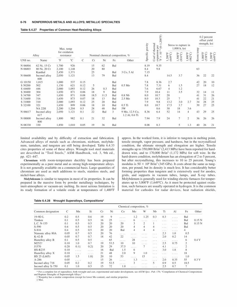
limited availability and by difficulty of extraction and fabrication.Advanced alloys of metals such as chromium, niobium, molybde-num, tantalum, and tungsten are still being developed. Table 6.4.33cites properties of some of these alloys. Wrought tool steel materialsare described in “Tool Steels,” ASM Handbook, vol. 3, 9th ed.,pp. 421–447.
Chromium with room-temperature ductility has been preparedexperimentally as a pure metal and as strong high-temperature alloys.It is not generally available on a commercial basis. Large quantities ofchromium are used as melt additions to steels, stainless steels, andnickel-base alloys.
Molybdenum is similar to tungsten in most of its properties. It can beprepared in the massive form by powder metallurgy techniques, byinert-atmosphere or vacuum-arc melting. Its most serious limitation isits ready formation of a volatile oxide at temperatures of 1,4008F
approx. In the worked form, it is inferior to tungsten in melting point,tensile strength, vapor pressure, and hardness, but in the recrystallizedcondition, the ultimate strength and elongation are higher. Tensilestrengths up to 350,000 lb/in2 (2,413 MPa) have been reported for hard-drawn wire, and to 170,000 lb/in2 (1,172 MPa) for soft wire. In thehard-drawn condition, molybdenum has an elongation of 2 to 5 percent,but after recrystallizing, this increases to 10 to 25 percent. Young’smodulus is 50 # 106 lb/in2 (345 GPa). It costs about the same as tung-sten, per pound, but its density is much less. It has considerably betterforming properties than tungsten and is extensively used for anodes,grids, and supports in vacuum tubes, lamps, and X-ray tubes.Molybdenum is generally used for winding electric furnaces for temper-atures up to 3,0008F (1,6498C). As it must be protected against oxida-tion, such furnaces are usually operated in hydrogen. It is the commonmaterial for cathodes for radar devices, heat radiation shields,
6-76 NONFERROUS METALS AND ALLOYS; METALLIC SPECIALTIES
Table 6.4.27 Properties of Common Heat-Resisting Alloys
Max. tempfor oxidation
Alloy resistance Nominal chemical composition, %
UNS no. Name 8F 8C C Cr Ni Fe Other
N 06004 62 Ni, 15 Cr 1,700 926 15 62 Bal 8.19 9.35N 06003 80 Ni, 20 Cr 2,100 1,148 20 80 8.4 9.8 63
Kanthal 2,450 1,371 25 Bal 3 Co, 5 Al 7.15N 06600 Inconel alloy 2,050 1,121 13 79 Bal 8.4 14.5 3.7 36 22 22
600G 10150 1,015 1,000 537 0.15 Bal 7.8 8.36 2.7 42 20 10S 50200 502 1,150 621 0.12 5 Bal 0.5 Mo 7.8 7.31 6 1.5 27 18 12S 44600 446 2,000 1,093 0.12 26 0.3 Bal 7.6 6.67 4 1.2 S 30400 304 1,650 871 0.06 18 9 Bal 7.9 10.4 11 3.5 32 14 11S 34700 347 1,650 871 0.08 18.5 11.5 Bal 0.8 Nb 8.0 10.7 20 41 31 26S 31600 316 1,650 873 0.07 18 13 Bal 2.5 Mo 8.0 10.3 25 7 41 22 21S 31000 310 2,000 1,093 0.12 25 20 Bal 7.9 9.8 13.2 3.0 2.7 34 28 25S 32100 321 1,650 899 0.06 18 10 Bal 0.5 Ti 8.0 10.7 17.5 3.7 39 27 25
NA 22H 2,200 1,204 0.5 28 48 Bal 5W 8.6 30 18 3.6N 06617 Inconel alloy 2,050 1,121 0.1 22 Bal 3 9 Mo, 12.5 Co, 8.36 6.4 52 14 4 43 29 25
617 1.2 Al, 0.6 TiN 08800 Inconel alloy 1,800 982 0.1 21 32 Bal 7.94 7.9 24 7 2 36 26 26
800N 08330 330 1,850 1,010 0.05 19 36 Bal 8.08 8.3 5 1.3 40 26 21
Coef of thermal
expansion per
8F#10%6(0–1,2008F)
Specific gravity
0.2 percentoffset yieldstrength, ksi
1,2008F
(6498C)
1,5008F
(8168C)
1,8008F
(9828C)
Room temp
1,0008F
(5388C)
1,2008F
(6498C)
Stress to rupture in1,000 h, ksi
Table 6.4.28 Wrought Superalloys, Compositions*
Chemical composition, %
Common designation C Mn Si Cr Ni Co Mo W Nb Ti Al Fe Other
19-9D L 0.2 0.5 0.6 19 9 . . . . 1.2 1.25 0.3 0.3 . . . . BalTimken 0.1 0.5 0.5 16 25 . . . . 6 . . . . . . . . . . . . . . Bal 0.15 NL.C. N-155 0.1 0.5 0.5 20 20 20 3 2 1 . . . . . . . Bal 0.15 NS-590 0.4 0.5 0.5 20 20 20 4 4 4 . . . . . . . BalS-816 0.4 0.5 0.5 20 20 Bal 4 4 4 . . . . . . . 4Nimonic alloy 80A 0.05 0.7 0.5 20 76 . . . . . . . . . . . . . . . 2.3 1.0 0.5K-42-B 0.05 0.7 0.7 18 42 22 . . . . . . . . . . . 2.0 0.2 14Hastelloy alloy B 0.1 0.5 0.5 . . 65 . . . . 28 . . . . . . . . . . . . . . 6 0.4 VM252† 0.10 1.0 0.7 19 53.5 10 10 . . . . . . . 2.5 0.75 2J1570 0.20 0.1‡ 0.2‡ 20 29 37.5 . . . . 7 . . . 4.1 . . . . 2HS-R235 0.10 . . . . . . . . 16 Bal 1.5 6 . . . 3.0 1.8 8Hastelloy alloy X 0.10 . . . . . . . . 21 48 2.0 9 1.0 . . . . . . . . . . 18HS 25 (L605) 0.05 1.5 1.0‡ 20 10 53 . . . . 15 . . . . . . . . . . 1.0A-286 0.05 . . . . 15 26 . . . . 1.3 . . . . . . . 2.0 0.35 55 0.3 VInconel alloy 718 0.05 0.2 0.2 19 52.5 . . . . 3 . . . . 5 0.9 0.5 18.5Inconel alloy X-750 0.1 1.0 0.5 15 72 1.0 . . . . . . . . . . . 2.5 0.7 7
* For a complete list of superalloys, both wrought and cast, experimental and under development, see ASTM Spec. Pub. 170, “Compilation of Chemical Compositionsand Rupture Strengths of Superstrength Alloys.”† Waspaloy has a similar composition (except for lower Mo content), and similar properties.‡ Max.
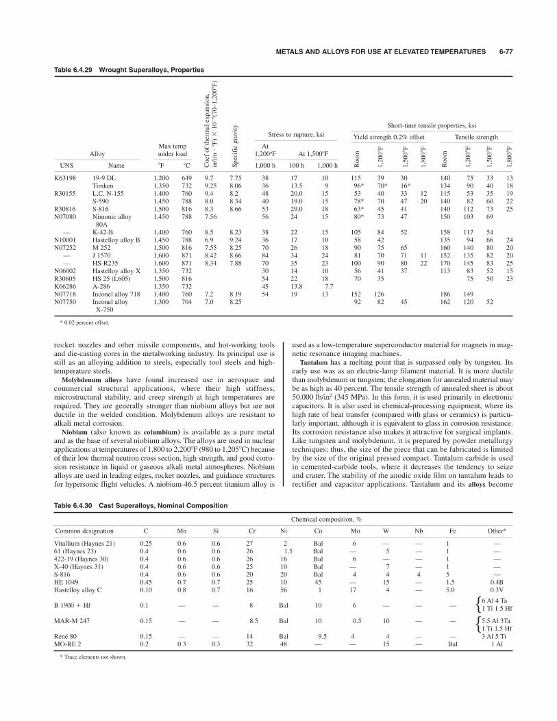
METALS AND ALLOYS FOR USE AT ELEVATED TEMPERATURES 6-77
rocket nozzles and other missile components, and hot-working toolsand die-casting cores in the metalworking industry. Its principal use isstill as an alloying addition to steels, especially tool steels and high-temperature steels.
Molybdenum alloys have found increased use in aerospace andcommercial structural applications, where their high stiffness,microstructural stability, and creep strength at high temperatures arerequired. They are generally stronger than niobium alloys but are notductile in the welded condition. Molybdenum alloys are resistant toalkali metal corrosion.
Niobium (also known as columbium) is available as a pure metaland as the base of several niobium alloys. The alloys are used in nuclearapplications at temperatures of 1,800 to 2,2008F (980 to 1,2058C) becauseof their low thermal neutron cross section, high strength, and good corro-sion resistance in liquid or gaseous alkali metal atmospheres. Niobiumalloys are used in leading edges, rocket nozzles, and guidance structuresfor hypersonic flight vehicles. A niobium-46.5 percent titanium alloy is
used as a low-temperature superconductor material for magnets in mag-netic resonance imaging machines.
Tantalum has a melting point that is surpassed only by tungsten. Itsearly use was as an electric-lamp filament material. It is more ductilethan molybdenum or tungsten; the elongation for annealed material maybe as high as 40 percent. The tensile strength of annealed sheet is about50,000 lb/in2 (345 MPa). In this form, it is used primarily in electroniccapacitors. It is also used in chemical-processing equipment, where itshigh rate of heat transfer (compared with glass or ceramics) is particu-larly important, although it is equivalent to glass in corrosion resistance.Its corrosion resistance also makes it attractive for surgical implants.Like tungsten and molybdenum, it is prepared by powder metallurgytechniques; thus, the size of the piece that can be fabricated is limitedby the size of the original pressed compact. Tantalum carbide is usedin cemented-carbide tools, where it decreases the tendency to seizeand crater. The stability of the anodic oxide film on tantalum leads torectifier and capacitor applications. Tantalum and its alloys become
Table 6.4.29 Wrought Superalloys, Properties
Stress to rupture, ksi
Max temp AtAlloy under load 1,200oF At 1,5008F
UNS Name 8F 8C 1,000 h 100 h 1,000 h
K63198 19-9 DL 1,200 649 9.7 7.75 38 17 10 115 39 30 140 75 33 13Timken 1,350 732 9.25 8.06 36 13.5 9 96* 70* 16* 134 90 40 18
R30155 L.C. N-155 1,400 760 9.4 8.2 48 20.0 15 53 40 33 12 115 53 35 19S-590 1,450 788 8.0 8.34 40 19.0 15 78* 70 47 20 140 82 60 22
R30816 S-816 1,500 816 8.3 8.66 53 29.0 18 63* 45 41 140 112 73 25N07080 Nimonic alloy 1,450 788 7.56 56 24 15 80* 73 47 150 103 69
80A— K-42-B 1,400 760 8.5 8.23 38 22 15 105 84 52 158 117 54
N10001 Hastelloy alloy B 1,450 788 6.9 9.24 36 17 10 58 42 135 94 66 24N07252 M 252 1,500 816 7.55 8.25 70 26 18 90 75 65 160 140 80 20
— J 1570 1,600 871 8.42 8.66 84 34 24 81 70 71 11 152 135 82 20— HS-R235 1,600 871 8.34 7.88 70 35 23 100 90 80 22 170 145 83 25
N06002 Hastelloy alloy X 1,350 732 30 14 10 56 41 37 113 83 52 15R30605 HS 25 (L605) 1,500 816 54 22 18 70 35 75 50 23K66286 A-286 1,350 732 45 13.8 7.7N07718 Inconel alloy 718 1,400 760 7.2 8.19 54 19 13 152 126 186 149N07750 Inconel alloy 1,300 704 7.0 8.25 92 82 45 162 120 52
X-750
* 0.02 percent offset.
Short-time tensile properties, ksi
Yield strength 0.2% offset Tensile strength
Room
Coef of thermal expansion,
in/(in"8F)#10%6(70–1,2008F)
Specific gravity
1,2008F
1,5008F
1,8008F
Room
1,2008F
1,5008F
1,8008F
Table 6.4.30 Cast Superalloys, Nominal Composition
Chemical composition, %
Common designation C Mn Si Cr Ni Co Mo W Nb Fe Other*
Vitallium (Haynes 21) 0.25 0.6 0.6 27 2 Bal 6 — — 1 —61 (Haynes 23) 0.4 0.6 0.6 26 1.5 Bal — 5 — 1 —422-19 (Haynes 30) 0.4 0.6 0.6 26 16 Bal 6 — — 1 —X-40 (Haynes 31) 0.4 0.6 0.6 25 10 Bal — 7 — 1 —S-816 0.4 0.6 0.6 20 20 Bal 4 4 4 5 —HE 1049 0.45 0.7 0.7 25 10 45 — 15 — 1.5 0.4BHastelloy alloy C 0.10 0.8 0.7 16 56 1 17 4 — 5.0 0.3V
B 1900 $ Hf 0.1 — — 8 Bal 10 6 — — —
MAR-M 247 0.15 — — 8.5 Bal 10 0.5 10 — — 5.5 Al 3Ta1 Ti 1.5 Hf
René 80 0.15 — — 14 Bal 9.5 4 4 — — 3 Al 5 TiMO-RE 2 0.2 0.3 0.3 32 48 — — 15 — Bal 1 Al
* Trace elements not shown.
6 Al 4 Ta1 Ti 1 5 Hfhh
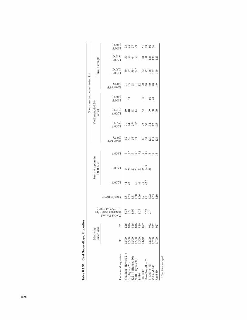
6-78
Table 6.4.31
Cast Superalloys,Properties
Short-time tensile properties, ksi
Max temp
Stress to rupture in
Yield strength 0.2%
under load
1,000 h, ksi
offset
Tensile strength
Common designation
8F8C
Vitallium (Haynes 21)
1,500
816
8.35
8.3
44
14
782
71
49
101
89
59
33
61(Haynes 23)
1,500
816
8.5
8.53
47
22
5.5
58
74
40
33
105
97
58
45
422-19 (Haynes 30)
1,500
816
8.07
8.31
21
755
37*
48
98
59*
64
37
N-40 (Haynes 31)
1,500
816
8.18
8.60
46
23
9.8
74
37*
44
101
77*
59
29
S-816
1,500
816
8.27
8.66
46
21
9.8
112
HE 1049
1,650
899
8.9
75
35
780
72
62
36
90
82
81
51
Hastelloy alloy C
7.73
8.91
42.5
14.5
1.4
54
50
130
87
51
19
B 1900 $
Hf
1,800
982
7.7
8.22
55
15
120
134
109
60
140
146
126
80
MAR-M 247
1,700
927
8.53
18
117
117
108
48
140
152
130
76
René 80
1,700
927
8.16
15
124
105
90
149
149
123
* Specimen not aged.
Coef of Thermalexpansion in/(in "8F)3 10
%6(70–1,2008F)
Specific gravity
1,2008F
1,5008F
1,8008F
Room 688F(208C)
1,2008F(6508C)
1,5008F(8168C)
18008F(9828C)
Room 688F(208C)
1,2008F(6508C)
1,5008F(8168C)
18008F(9828C)
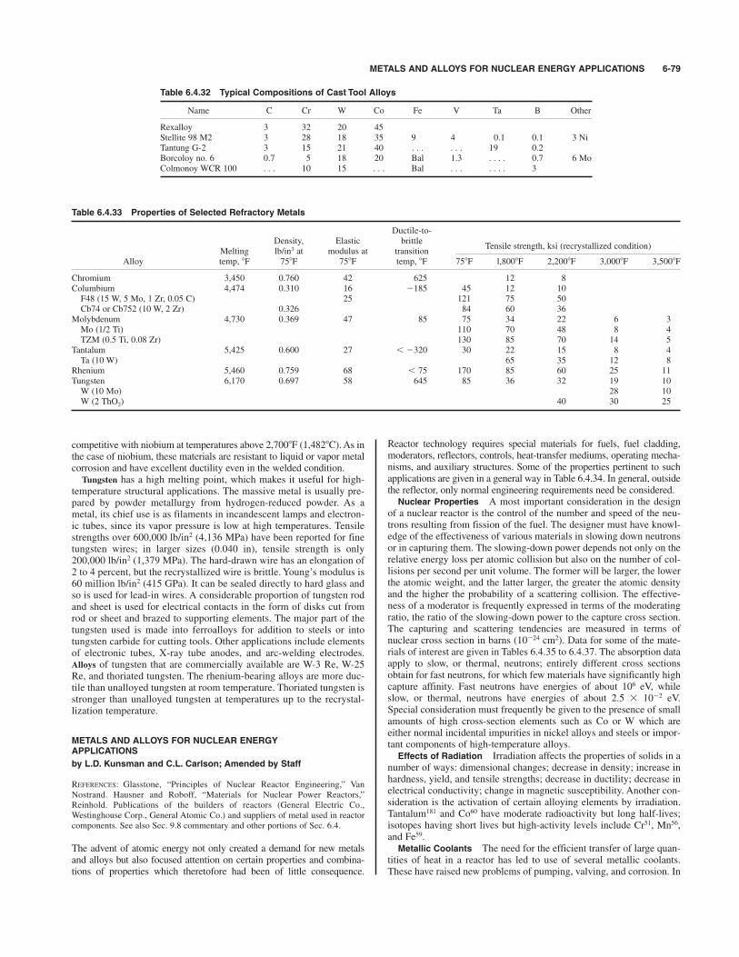
METALS AND ALLOYS FOR NUCLEAR ENERGY APPLICATIONS 6-79
competitive with niobium at temperatures above 2,7008F (1,4828C). As inthe case of niobium, these materials are resistant to liquid or vapor metalcorrosion and have excellent ductility even in the welded condition.
Tungsten has a high melting point, which makes it useful for high-temperature structural applications. The massive metal is usually pre-pared by powder metallurgy from hydrogen-reduced powder. As ametal, its chief use is as filaments in incandescent lamps and electron-ic tubes, since its vapor pressure is low at high temperatures. Tensilestrengths over 600,000 lb/in2 (4,136 MPa) have been reported for finetungsten wires; in larger sizes (0.040 in), tensile strength is only200,000 lb/in2 (1,379 MPa). The hard-drawn wire has an elongation of2 to 4 percent, but the recrystallized wire is brittle. Young’s modulus is60 million lb/in2 (415 GPa). It can be sealed directly to hard glass andso is used for lead-in wires. A considerable proportion of tungsten rodand sheet is used for electrical contacts in the form of disks cut fromrod or sheet and brazed to supporting elements. The major part of thetungsten used is made into ferroalloys for addition to steels or intotungsten carbide for cutting tools. Other applications include elementsof electronic tubes, X-ray tube anodes, and arc-welding electrodes.Alloys of tungsten that are commercially available are W-3 Re, W-25Re, and thoriated tungsten. The rhenium-bearing alloys are more duc-tile than unalloyed tungsten at room temperature. Thoriated tungsten isstronger than unalloyed tungsten at temperatures up to the recrystal-lization temperature.
METALS AND ALLOYS FOR NUCLEAR ENERGYAPPLICATIONS
by L.D. Kunsman and C.L. Carlson; Amended by Staff
REFERENCES: Glasstone, “Principles of Nuclear Reactor Engineering,” VanNostrand. Hausner and Roboff, “Materials for Nuclear Power Reactors,”Reinhold. Publications of the builders of reactors (General Electric Co.,Westinghouse Corp., General Atomic Co.) and suppliers of metal used in reactorcomponents. See also Sec. 9.8 commentary and other portions of Sec. 6.4.
The advent of atomic energy not only created a demand for new metalsand alloys but also focused attention on certain properties and combina-tions of properties which theretofore had been of little consequence.
Reactor technology requires special materials for fuels, fuel cladding,moderators, reflectors, controls, heat-transfer mediums, operating mecha-nisms, and auxiliary structures. Some of the properties pertinent to suchapplications are given in a general way in Table 6.4.34. In general, outsidethe reflector, only normal engineering requirements need be considered.Nuclear Properties A most important consideration in the design
of a nuclear reactor is the control of the number and speed of the neu-trons resulting from fission of the fuel. The designer must have knowl-edge of the effectiveness of various materials in slowing down neutronsor in capturing them. The slowing-down power depends not only on therelative energy loss per atomic collision but also on the number of col-lisions per second per unit volume. The former will be larger, the lowerthe atomic weight, and the latter larger, the greater the atomic densityand the higher the probability of a scattering collision. The effective-ness of a moderator is frequently expressed in terms of the moderatingratio, the ratio of the slowing-down power to the capture cross section.The capturing and scattering tendencies are measured in terms ofnuclear cross section in barns (10%24 cm2). Data for some of the mate-rials of interest are given in Tables 6.4.35 to 6.4.37. The absorption dataapply to slow, or thermal, neutrons; entirely different cross sectionsobtain for fast neutrons, for which few materials have significantly highcapture affinity. Fast neutrons have energies of about 106 eV, whileslow, or thermal, neutrons have energies of about 2.5 # 10%2 eV.Special consideration must frequently be given to the presence of smallamounts of high cross-section elements such as Co or W which areeither normal incidental impurities in nickel alloys and steels or impor-tant components of high-temperature alloys.Effects of Radiation Irradiation affects the properties of solids in a
number of ways: dimensional changes; decrease in density; increase inhardness, yield, and tensile strengths; decrease in ductility; decrease inelectrical conductivity; change in magnetic susceptibility. Another con-sideration is the activation of certain alloying elements by irradiation.Tantalum181 and Co60 have moderate radioactivity but long half-lives;isotopes having short lives but high-activity levels include Cr51, Mn56,and Fe59.Metallic Coolants The need for the efficient transfer of large quan-
tities of heat in a reactor has led to use of several metallic coolants.These have raised new problems of pumping, valving, and corrosion. In
Table 6.4.32 Typical Compositions of Cast Tool Alloys
Name C Cr W Co Fe V Ta B Other
Rexalloy 3 32 20 45Stellite 98 M2 3 28 18 35 9 4 0.1 0.1 3 NiTantung G-2 3 15 21 40 . . . . . . 19 0.2Borcoloy no. 6 0.7 5 18 20 Bal 1.3 . . . . 0.7 6 MoColmonoy WCR 100 . . . 10 15 . . . Bal . . . . . . . 3
Table 6.4.33 Properties of Selected Refractory Metals
Ductile-to-Density, Elastic brittle
Tensile strength, ksi (recrystallized condition)Melting lb/in3 at modulus at transition
Alloy temp, 8F 758F 758F temp, 8F 758F l,8008F 2,2008F 3,0008F 3,5008F
Chromium 3,450 0.760 42 625 12 8Columbium 4,474 0.310 16 %185 45 12 10F48 (15 W, 5 Mo, 1 Zr, 0.05 C) 25 121 75 50Cb74 or Cb752 (10 W, 2 Zr) 0.326 84 60 36
Molybdenum 4,730 0.369 47 85 75 34 22 6 3Mo (1/2 Ti) 110 70 48 8 4TZM (0.5 Ti, 0.08 Zr) 130 85 70 14 5
Tantalum 5,425 0.600 27 ) %320 30 22 15 8 4Ta (10 W) 65 35 12 8
Rhenium 5,460 0.759 68 ) 75 170 85 60 25 11Tungsten 6,170 0.697 58 645 85 36 32 19 10W (10 Mo) 28 10W (2 ThO2) 40 30 25
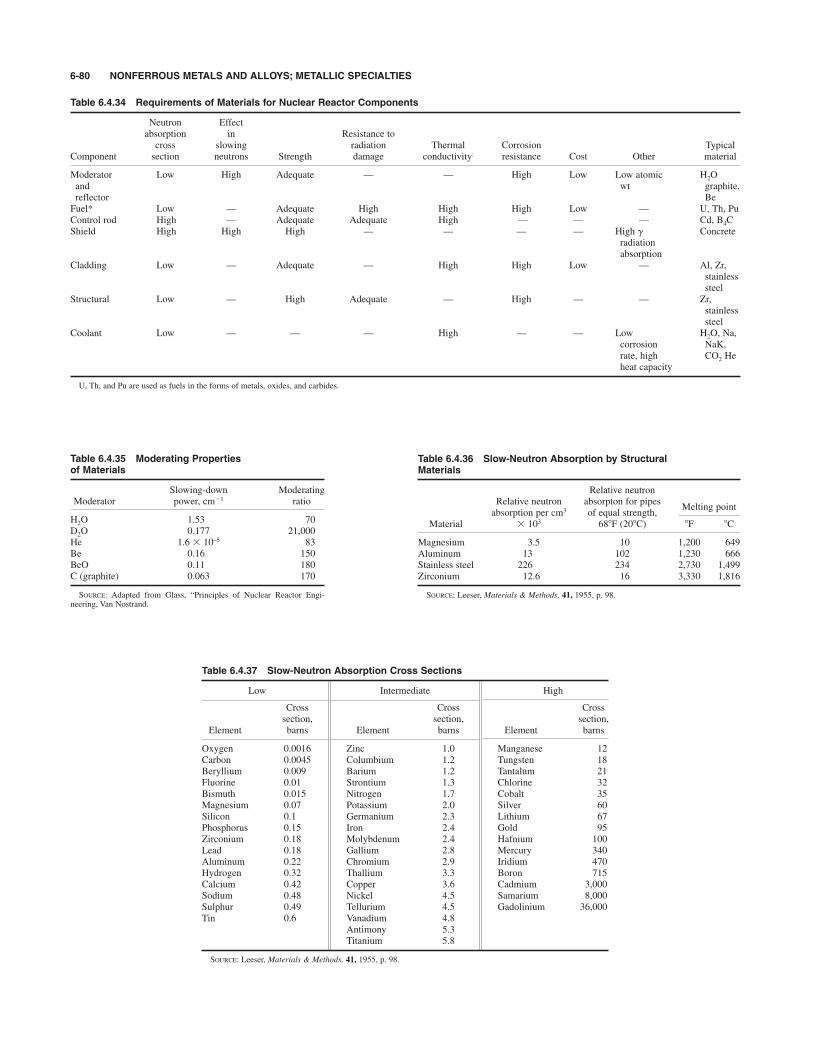
6-80 NONFERROUS METALS AND ALLOYS; METALLIC SPECIALTIES
Table 6.4.35 Moderating Properties of Materials
Slowing-down ModeratingModerator power, cm%1 ratio
H2O 1.53 70D2O 0.177 21,000He 1.6 # 10–5 83Be 0.16 150BeO 0.11 180C (graphite) 0.063 170
SOURCE: Adapted from Glass, “Principles of Nuclear Reactor Engi-neering, Van Nostrand.
Table 6.4.34 Requirements of Materials for Nuclear Reactor Components
Neutron Effectabsorption in Resistance tocross slowing radiation Thermal Corrosion Typical
Component section neutrons Strength damage conductivity: resistance Cost Other material
Moderator Low High Adequate — — High Low Low atomic H2Oand wt graphite,reflector BeFuel* Low — Adequate High High High Low — U, Th, PuControl rod High — Adequate Adequate High — — — Cd, B4CShield High High High — — — — High g Concrete
radiationabsorption
Cladding Low — Adequate — High High Low — Al, Zr,stainlesssteel
Structural Low — High Adequate — High — — Zr,stainlesssteel
Coolant Low — — — High — — Low H2O, Na, corrosion NaK,rate, high CO2 Heheat capacity
U, Th, and Pu are used as fuels in the forms of metals, oxides, and carbides.
Table 6.4.36 Slow-Neutron Absorption by StructuralMaterials
Relative neutronRelative neutron absorpton for pipes
Melting pointabsorption per cm3 of equal strength,
Material # 103 688F (208C) 8F 8C
Magnesium 3.5 10 1,200 649Aluminum 13 102 1,230 666Stainless steel 226 234 2,730 1,499Zirconium 12.6 16 3,330 1,816
SOURCE: Leeser, Materials & Methods, 41, 1955, p. 98.
Table 6.4.37 Slow-Neutron Absorption Cross Sections
Low Intermediate High
Cross Cross Crosssection, section, section,
Element barns Element barns Element barns
Oxygen 0.0016 Zinc 1.0 Manganese 12Carbon 0.0045 Columbium 1.2 Tungsten 18Beryllium 0.009 Barium 1.2 Tantalum 21Fluorine 0.01 Strontium 1.3 Chlorine 32Bismuth 0.015 Nitrogen 1.7 Cobalt 35Magnesium 0.07 Potassium 2.0 Silver 60Silicon 0.1 Germanium 2.3 Lithium 67Phosphorus 0.15 Iron 2.4 Gold 95Zirconium 0.18 Molybdenum 2.4 Hafnium 100Lead 0.18 Gallium 2.8 Mercury 340Aluminum 0.22 Chromium 2.9 Iridium 470Hydrogen 0.32 Thallium 3.3 Boron 715Calcium 0.42 Copper 3.6 Cadmium 3,000Sodium 0.48 Nickel 4.5 Samarium 8,000Sulphur 0.49 Tellurium 4.5 Gadolinium 36,000Tin 0.6 Vanadium 4.8
Antimony 5.3Titanium 5.8
SOURCE: Leeser, Materials & Methods, 41, 1955, p. 98.
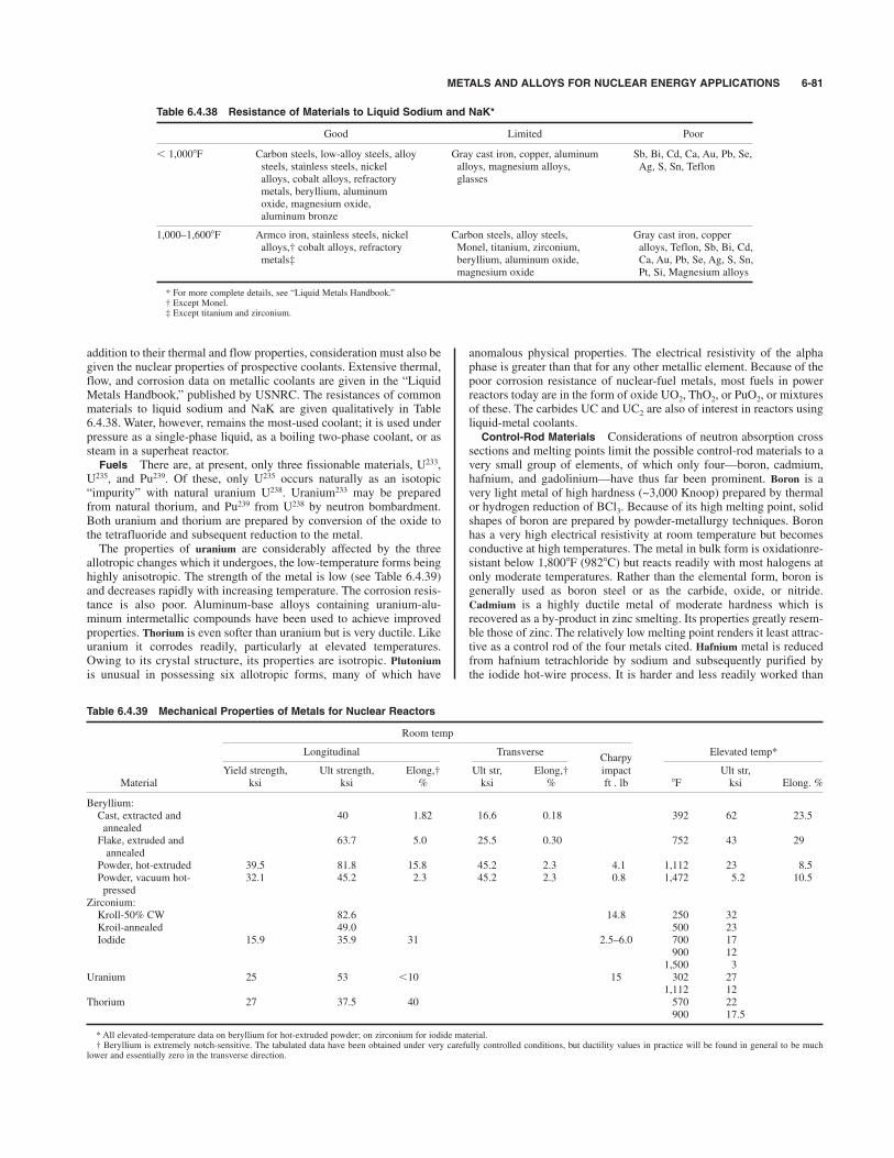
METALS AND ALLOYS FOR NUCLEAR ENERGY APPLICATIONS 6-81
addition to their thermal and flow properties, consideration must also begiven the nuclear properties of prospective coolants. Extensive thermal,flow, and corrosion data on metallic coolants are given in the “LiquidMetals Handbook,” published by USNRC. The resistances of commonmaterials to liquid sodium and NaK are given qualitatively in Table6.4.38. Water, however, remains the most-used coolant; it is used underpressure as a single-phase liquid, as a boiling two-phase coolant, or assteam in a superheat reactor.Fuels There are, at present, only three fissionable materials, U233,
U235, and Pu239. Of these, only U235 occurs naturally as an isotopic“impurity” with natural uranium U238. Uranium233 may be preparedfrom natural thorium, and Pu239 from U238 by neutron bombardment.Both uranium and thorium are prepared by conversion of the oxide tothe tetrafluoride and subsequent reduction to the metal.The properties of uranium are considerably affected by the three
allotropic changes which it undergoes, the low-temperature forms beinghighly anisotropic. The strength of the metal is low (see Table 6.4.39)and decreases rapidly with increasing temperature. The corrosion resis-tance is also poor. Aluminum-base alloys containing uranium-alu-minum intermetallic compounds have been used to achieve improvedproperties. Thorium is even softer than uranium but is very ductile. Likeuranium it corrodes readily, particularly at elevated temperatures.Owing to its crystal structure, its properties are isotropic. Plutoniumis unusual in possessing six allotropic forms, many of which have
anomalous physical properties. The electrical resistivity of the alphaphase is greater than that for any other metallic element. Because of thepoor corrosion resistance of nuclear-fuel metals, most fuels in powerreactors today are in the form of oxide UO2, ThO2, or PuO2, or mixturesof these. The carbides UC and UC2 are also of interest in reactors usingliquid-metal coolants.Control-Rod Materials Considerations of neutron absorption cross
sections and melting points limit the possible control-rod materials to avery small group of elements, of which only four—boron, cadmium,hafnium, and gadolinium—have thus far been prominent. Boron is avery light metal of high hardness (~3,000 Knoop) prepared by thermalor hydrogen reduction of BCl3. Because of its high melting point, solidshapes of boron are prepared by powder-metallurgy techniques. Boronhas a very high electrical resistivity at room temperature but becomesconductive at high temperatures. The metal in bulk form is oxidationre-sistant below 1,8008F (9828C) but reacts readily with most halogens atonly moderate temperatures. Rather than the elemental form, boron isgenerally used as boron steel or as the carbide, oxide, or nitride.Cadmium is a highly ductile metal of moderate hardness which isrecovered as a by-product in zinc smelting. Its properties greatly resem-ble those of zinc. The relatively low melting point renders it least attrac-tive as a control rod of the four metals cited. Hafnium metal is reducedfrom hafnium tetrachloride by sodium and subsequently purified bythe iodide hot-wire process. It is harder and less readily worked than
Table 6.4.39 Mechanical Properties of Metals for Nuclear Reactors
Room temp
Longitudinal TransverseCharpy
Elevated temp*
Yield strength, Ult strength, Elong,† Ult str, Elong,† impact Ult str,Material ksi ksi % ksi % ft . lb 8F ksi Elong. %
Beryllium:Cast, extracted and 40 1.82 16.6 0.18 392 62 23.5annealedFlake, extruded and 63.7 5.0 25.5 0.30 752 43 29annealed
Powder, hot-extruded 39.5 81.8 15.8 45.2 2.3 4.1 1,112 23 8.5Powder, vacuum hot- 32.1 45.2 2.3 45.2 2.3 0.8 1,472 5.2 10.5pressed
Zirconium:Kroll-50% CW 82.6 14.8 250 32Kroil-annealed 49.0 500 23Iodide 15.9 35.9 31 2.5–6.0 700 17
900 121,500 3
Uranium 25 53 )10 15 302 271,112 12
Thorium 27 37.5 40 570 22900 17.5
* All elevated-temperature data on beryllium for hot-extruded powder; on zirconium for iodide material.† Beryllium is extremely notch-sensitive. The tabulated data have been obtained under very carefully controlled conditions, but ductility values in practice will be found in general to be much
lower and essentially zero in the transverse direction.
Table 6.4.38 Resistance of Materials to Liquid Sodium and NaK*
Good Limited Poor
) 1,0008F Carbon steels, low-alloy steels, alloy Gray cast iron, copper, aluminum Sb, Bi, Cd, Ca, Au, Pb, Se,steels, stainless steels, nickel alloys, magnesium alloys, Ag, S, Sn, Teflonalloys, cobalt alloys, refractory glassesmetals, beryllium, aluminumoxide, magnesium oxide,aluminum bronze
1,000–1,6008F Armco iron, stainless steels, nickel Carbon steels, alloy steels, Gray cast iron, copperalloys,† cobalt alloys, refractory Monel, titanium, zirconium, alloys, Teflon, Sb, Bi, Cd,metals‡ beryllium, aluminum oxide, Ca, Au, Pb, Se, Ag, S, Sn,
magnesium oxide Pt, Si, Magnesium alloys
* For more complete details, see “Liquid Metals Handbook.”† Except Monel.‡ Except titanium and zirconium.
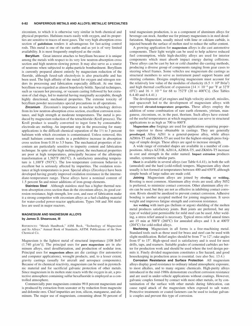
zirconium, to which it is otherwise very similar in both chemical andphysical properties. Hafnium reacts easily with oxygen, and its proper-ties are sensitive to traces of most gases. The very high absorption crosssection of gadolinium renders it advantageous for fast-acting controlrods. This metal is one of the rare earths and as yet is of very limitedavailability. It is most frequently employed as the oxide.
Beryllium Great interest attaches to beryllium because it is uniqueamong the metals with respect to its very low neutron-absorption crosssection and high neutron-slowing power. It may also serve as a sourceof neutrons when subjected to alpha-particle bombardment. Berylliumis currently prepared almost entirely by magnesium reduction of thefluoride, although fused-salt electrolysis is also practicable and hasbeen used. The high affinity of the metal for oxygen and nitrogen ren-ders its processing and fabrication especially difficult. At one time,beryllium was regarded as almost hopelessly brittle. Special techniques,such as vacuum hot pressing, or vacuum casting followed by hot extru-sion of clad slugs, led to material having marginally acceptable, thoughhighly directional, mechanical properties. The extreme toxicity ofberyllium powder necessitates special precautions in all operations.Zirconium Zirconium’s importance in nuclear technology derives
from its low neutron-absorption cross section, excellent corrosion resis-tance, and high strength at moderate temperatures. The metal is pro-duced by magnesium reduction of the tetrachloride (Kroll process). TheKroll product is usually converted to ingot form by consumable-electrode-arc melting. An important step in the processing for manyapplications is the difficult chemical separation of the 1 to 3 percenthafnium with which zirconium is contaminated. Unless removed, thissmall hafnium content results in a prohibitive increase in absorptioncross section from 0.18 to 3.5 barns. The mechanical properties of zir-conium are particularly sensitive to impurity content and fabricationtechnique. In spite of the high melting point, the mechanical propertiesare poor at high temperatures, principally because of the allotropictransformation at 1,5858F (8638C). A satisfactory annealing tempera-ture is 1,1008F (5938C). The low-temperature corrosion behavior isexcellent but is seriously affected by impurities. The oxidation resis-tance at high temperatures is poor. Special alloys (Zircoloys) have beendeveloped having greatly improved oxidation resistance in the interme-diate-temperature range. These alloys have a nominal content of1.5 percent Sn and minor additions of iron-group elements.Stainless Steel Although stainless steel has a higher thermal neu-
tron-absorption cross section than do the zirconium alloys, its good cor-rosion resistance, high strength, low cost, and ease of fabrication makeit a strong competitor with zirconium alloys as a fuel-cladding materialfor water-cooled power-reactor applications. Types 348 and 304 stain-less are used in major reactors.
MAGNESIUM AND MAGNESIUM ALLOYS
by James D. Shearouse, III
REFERENCES: “Metals Handbook,” ASM. Beck, “Technology of Magnesiumand Its Alloys.” Annual Book of Standards, ASTM. Publications of the DowChemical Co.
Magnesium is the lightest metal of structural importance [108 lb/ft3
(1.740 g/cm3)]. The principal uses for pure magnesium are in alu-minum alloys, steel desulfurization, and production of nodular iron.Principal uses for magnesium alloys are die castings (for automotiveand computer applications), wrought products, and, to a lesser extent,gravity castings (usually for aircraft and aerospace components).Because of its chemical reactivity, magnesium can be used in pyrotech-nic material and for sacrificial galvanic protection of other metals.Since magnesium in its molten state reacts with the oxygen in air, a pro-tective atmosphere containing sulfur hexafluoride is employed as a con-trolled atmosphere.Commercially pure magnesium contains 99.8 percent magnesium and
is produced by extraction from seawater or by reduction from magnesiteand dolomite ores. Chief impurities are iron, silicon, manganese, and alu-minum. The major use of magnesium, consuming about 50 percent of
1⁄2
total magnesium production, is as a component of aluminum alloys forbeverage can stock. Another use for primary magnesium is in steel desul-furization. Magnesium, usually mixed with lime or calcium carbide, isinjected beneath the surface of molten steel to reduce the sulfur content.A growing application for magnesium alloys is die cast automotive
components. Their light weight can be used to help achieve reducedfuel consumption, while high-ductility alloys are used for interiorcomponents which must absorb impact energy during collisions.These alloys can be cast by hot or cold chamber die-casting methods,producing a diverse group of components ranging from gear cases tosteering wheel frames. Some vehicles use magnesium die castings asstructural members to serve as instrument panel support beams andsteering columns. Designs employing magnesium must account forthe relatively low value of the modulus of elasticity (6.5 # 106 lb/in2)and high thermal coefficient of expansion [14 # 10%6 per 8F at 328F(08C) and 16 # 10%6 for 68 to 7528F (20 to 4008C)]. (See Tables6.4.40 and 6.4.41.)The development of jet engines and high-velocity aircraft, missiles,
and spacecraft led to the development of magnesium alloys withimproved elevated-temperature properties. These alloys employ theaddition of some combination of rare earth elements, yttrium, man-ganese, zirconium, or, in the past, thorium. Such alloys have extend-ed the useful temperatures at which magnesium can serve in structuralapplications to as high as 700 to 8008F.
Magnesium alloy forgings are used for applications requiring proper-ties superior to those obtainable in castings. They are generallypressforged. Alloy AZ61 is a general-purpose alloy, while alloysAZ80A-T5 and ZK60A-T5 are used for the highest-strength press forg-ings of simple design. These alloys are aged to increase strength.A wide range of extruded shapes are available in a number of com-
positions. Alloys AZ31B, AZ61A, AZ80A-T5, and ZK60A-T5 increasein cost and strength in the order named. Impact extrusion producessmaller, symmetric tubular parts.
Sheet is available in several alloys (see Table 6.4.41), in both the soft(annealed) and the hard (cold-rolled) tempers. Magnesium alloy sheetusually is hot-formed at temperatures between 400 and 6508F, althoughsimple bends of large radius are made cold.Joining Magnesium alloys are joined by riveting or welding.
Riveting is most common. Aluminum alloy rivets are used; alloy 5052is preferred, to minimize contact corrosion. Other aluminum alloy riv-ets can be used, but they are not as effective in inhibiting contact corro-sion. Rivets should be anodized to prevent contact corrosion. Adhesivebonding is another accepted method for joining magnesium. It savesweight and improves fatigue strength and corrosion resistance.
Arc welding with inert-gas (helium or argon) shielding of the moltenmetal produces satisfactory joints. Butt joints are preferred, but anytype of welded joint permissible for mild steel can be used. After weld-ing, a stress relief anneal is necessary. Typical stress relief anneal timesare 15 min at 5008F (2608C) for annealed alloys and 1 h at 4008F(2048C) for cold-rolled alloys.Machining Magnesium in all forms is a free-machining metal.
Standard tools such as those used for brass and steel can be used withslight modification. Relief angles should be from 78 to 128; rake anglesfrom 08 to 158. High-speed steel is satisfactory and is used for mostdrills, taps, and reamers. Suitable grades of cemented carbides are bet-ter for production work and should be used where the tool design per-mits it. Finely divided magnesium constitutes a fire hazard, and goodhousekeeping in production areas is essential. (see also Sec. 13.4.)Corrosion Resistance and Surface Protection All magnesium
alloys display good resistance to ordinary inland atmospheric exposure,to most alkalies, and to many organic chemicals. High-purity alloysintroduced in the mid-1980s demonstrate excellent corrosion resistanceand are used in under-vehicle applications without coatings. However,galvanic couples formed by contact with most other metals, or by con-tamination of the surface with other metals during fabrication, cancause rapid attack of the magnesium when exposed to salt water.Protective treatments or coated fasteners can be used to isolate galvan-ic couples and prevent this type of corrosion.
6-82 NONFERROUS METALS AND ALLOYS; METALLIC SPECIALTIES
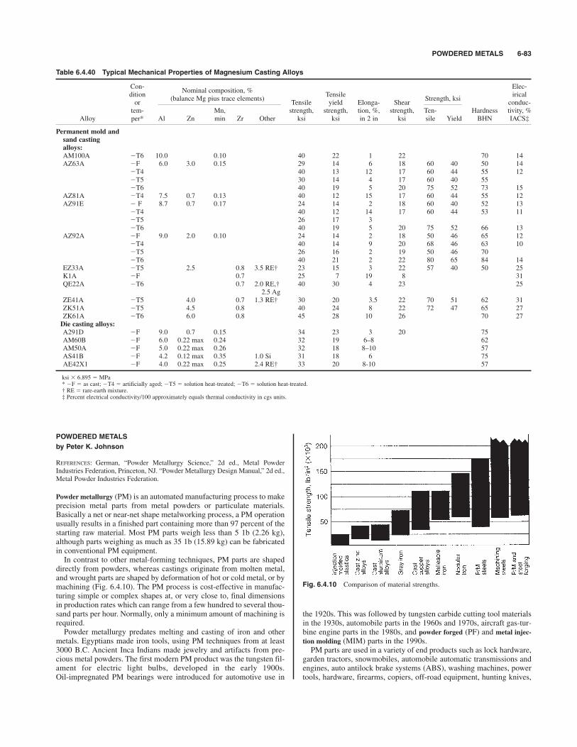
POWDERED METALS 6-83
POWDERED METALS
by Peter K. Johnson
REFERENCES: German, “Powder Metallurgy Science,” 2d ed., Metal PowderIndustries Federation, Princeton, NJ. “Powder Metallurgy Design Manual,” 2d ed.,Metal Powder Industries Federation.
Powder metallurgy (PM) is an automated manufacturing process to makeprecision metal parts from metal powders or particulate materials.Basically a net or near-net shape metalworking process, a PM operationusually results in a finished part containing more than 97 percent of thestarting raw material. Most PM parts weigh less than 5 1b (2.26 kg),although parts weighing as much as 35 1b (15.89 kg) can be fabricatedin conventional PM equipment.In contrast to other metal-forming techniques, PM parts are shaped
directly from powders, whereas castings originate from molten metal,and wrought parts are shaped by deformation of hot or cold metal, or bymachining (Fig. 6.4.10). The PM process is cost-effective in manufac-turing simple or complex shapes at, or very close to, final dimensionsin production rates which can range from a few hundred to several thou-sand parts per hour. Normally, only a minimum amount of machining isrequired.Powder metallurgy predates melting and casting of iron and other
metals. Egyptians made iron tools, using PM techniques from at least3000 B.C. Ancient Inca Indians made jewelry and artifacts from pre-cious metal powders. The first modern PM product was the tungsten fil-ament for electric light bulbs, developed in the early 1900s.Oil-impregnated PM bearings were introduced for automotive use in
the 1920s. This was followed by tungsten carbide cutting tool materialsin the 1930s, automobile parts in the 1960s and 1970s, aircraft gas-tur-bine engine parts in the 1980s, and powder forged (PF) and metal injec-
tion molding (MIM) parts in the 1990s.PM parts are used in a variety of end products such as lock hardware,
garden tractors, snowmobiles, automobile automatic transmissions andengines, auto antilock brake systems (ABS), washing machines, powertools, hardware, firearms, copiers, off-road equipment, hunting knives,
Table 6.4.40 Typical Mechanical Properties of Magnesium Casting Alloys
Con-Nominal composition, %
Elec-dition
(balance Mg pius trace elements)Tensile
Strength, ksiirical
or Tensile yield Elonga- Shear conduc-tem- Mn, strength, strength, tion, %, strength, Ten- Hardness tivity, %
Alloy per* Al Zn min Zr Other ksi ksi in 2 in ksi sile Yield BHN IACS‡
Permanent mold and
sand casting
alloys:
AM100A %T6 10.0 0.10 40 22 1 22 70 14AZ63A %F 6.0 3.0 0.15 29 14 6 18 60 40 50 14
%T4 40 13 12 17 60 44 55 12%T5 30 14 4 17 60 40 55%T6 40 19 5 20 75 52 73 15
AZ81A %T4 7.5 0.7 0.13 40 12 15 17 60 44 55 12AZ91E % F 8.7 0.7 0.17 24 14 2 18 60 40 52 13
%T4 40 12 14 17 60 44 53 11%T5 26 17 3%T6 40 19 5 20 75 52 66 13
AZ92A %F 9.0 2.0 0.10 24 14 2 18 50 46 65 12%T4 40 14 9 20 68 46 63 10%T5 26 16 2 19 50 46 70%T6 40 21 2 22 80 65 84 14
EZ33A %T5 2.5 0.8 3.5 RE† 23 15 3 22 57 40 50 25K1A %F 0.7 25 7 19 8 31QE22A %T6 0.7 2.0 RE,† 40 30 4 23 25
2.5 AgZE41A %T5 4.0 0.7 1.3 RE† 30 20 3.5 22 70 51 62 31ZK51A %T5 4.5 0.8 40 24 8 22 72 47 65 27ZK61A %T6 6.0 0.8 45 28 10 26 70 27Die casting alloys:
A291D %F 9.0 0.7 0.15 34 23 3 20 75AM60B %F 6.0 0.22 max 0.24 32 19 6–8 62AM50A %F 5.0 0.22 max 0.26 32 18 8–10 57AS41B %F 4.2 0.12 max 0.35 1.0 Si 31 18 6 75AE42X1 %F 4.0 0.22 max 0.25 2.4 RE† 33 20 8-10 57
ksi # 6.895 MPa* %F as cast; %T4 artificially aged; %T5 solution heat-treated; %T6 solution heat-treated.† RE rare-earth mixture.‡ Percent electrical conductivity/100 approximately equals thermal conductivity in cgs units.
Fig. 6.4.10 Comparison of material strengths.

6-84
Table 6.4.41
Properties of Wrought Magnesium Alloys
Physical properties
Thermal
Room-temperature mechanical properties (typical)
conduc-
Electrical
Com-
Bearing
Nominal composition, %
tivity,
resistivity,
Tensile
pressive
strength, ksi
(balance Mg plus trace elements)
cgs units,
m&"cm,
Tensile
yield
Elonga-
yield
Shear
Alloy and
Density,
688F
688F
strength,
strength,
tion in
strength,
strength,
Ten-
Hardness
temper*
Al
Mn
Zn
Zr
lb/in3
(208C)
(208C)
ksi
ksi
2 in, %
ksi
ksi
sile
Yield
BHN
Extruded bars, rods, shapes
AZ31B-F
3.0
1.0
0.0639
0.18
9.2
38
29
15
14
19
56
33
49
AZ61A-F
6.5
1.0
0.0647
0.14
12.5
45
33
16
19
22
68
40
60
AZ80A-T5
8.5
0.5
0.0649
0.12
14.5
55
40
735
24
60
58
82
ZK60A-F
5.7
0.5
0.0659
0.28
6.0
49
38
14
33
24
76
56
75
-T5
5.7
0.5
0.0659
0.29
5.7
53
44
11
36
26
79
59
82
Extruded tube
AZ31B-F
3.0
1.0
0.0639
0.18
9.2
36
24
16
12
46
AZ61A-F
6.5
1.0
0.0647
0.14
12.5
41
24
14
16
50
ZK60A-F
5.7
0.5
0.0659
0.28
6.0
47
35
13
25
75
-T5
5.7
0.5
0.0659
0.29
5.7
50
40
11
30
82
M1A
1.2
0.0635
0.31
5.4
37
26
11
12
Sheet and plate
AZ31B-H24
3.0
1.0
0.0639
0.18
9.2
42
32
15
26
29
77
47
73
40
29
17
23
28
72
45
39
27
19
19
27
70
40
AZ31B-0
3.0
1.0
0.0639
0.18
9.2
37
22
21
16
26
66
37
56
M1A
1.2
0.0635
0.31
5.4
37
26
11
12
Tooling plate
AZ31B
3.0
1.0
0.0639
0.18
9.2
35
19
12
10
Tread plate
AZ31B
3.0
1.0
0.0639
0.18
9.2
35
19
14
11
52
See Sec. 1for conversion factors to SI units.
NOTE:For all above alloys: coefficient of thermal expansion 0.0000145; modulus of elasticity
6,500,000 lb/in2; Position’s ratio
0.35..
* Temper: %F as fabricated; %H24 strain-hardened, then partially annealed; %O fully annealed; %T5 artificially aged.
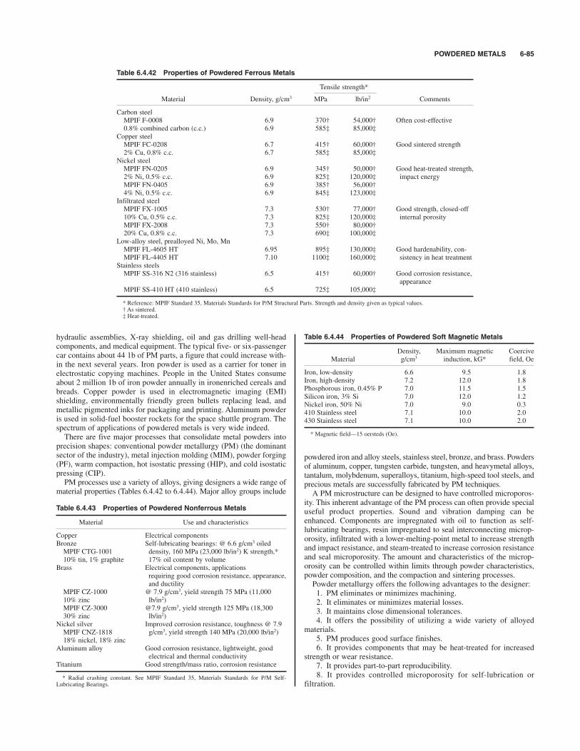
POWDERED METALS 6-85
hydraulic assemblies, X-ray shielding, oil and gas drilling well-headcomponents, and medical equipment. The typical five- or six-passengercar contains about 44 1b of PM parts, a figure that could increase with-in the next several years. Iron powder is used as a carrier for toner inelectrostatic copying machines. People in the United States consumeabout 2 million 1b of iron powder annually in ironenriched cereals andbreads. Copper powder is used in electromagnetic imaging (EMI)shielding, environmentally friendly green bullets replacing lead, andmetallic pigmented inks for packaging and printing. Aluminum powderis used in solid-fuel booster rockets for the space shuttle program. Thespectrum of applications of powdered metals is very wide indeed.There are five major processes that consolidate metal powders into
precision shapes: conventional powder metallurgy (PM) (the dominantsector of the industry), metal injection molding (MIM), powder forging(PF), warm compaction, hot isostatic pressing (HIP), and cold isostaticpressing (CIP). PM processes use a variety of alloys, giving designers a wide range of
material properties (Tables 6.4.42 to 6.4.44). Major alloy groups include
powdered iron and alloy steels, stainless steel, bronze, and brass. Powdersof aluminum, copper, tungsten carbide, tungsten, and heavymetal alloys,tantalum, molybdenum, superalloys, titanium, high-speed tool steels, andprecious metals are successfully fabricated by PM techniques.A PM microstructure can be designed to have controlled microporos-
ity. This inherent advantage of the PM process can often provide specialuseful product properties. Sound and vibration damping can beenhanced. Components are impregnated with oil to function as self-lubricating bearings, resin impregnated to seal interconnecting microp-orosity, infiltrated with a lower-melting-point metal to increase strengthand impact resistance, and steam-treated to increase corrosion resistanceand seal microporosity. The amount and characteristics of the microp-orosity can be controlled within limits through powder characteristics,powder composition, and the compaction and sintering processes.Powder metallurgy offers the following advantages to the designer:1. PM eliminates or minimizes machining.2. It eliminates or minimizes material losses.3. It maintains close dimensional tolerances.4. It offers the possibility of utilizing a wide variety of alloyed
materials.5. PM produces good surface finishes.6. It provides components that may be heat-treated for increased
strength or wear resistance.7. It provides part-to-part reproducibility.8. It provides controlled microporosity for self-lubrication or
filtration.
Table 6.4.42 Properties of Powdered Ferrous Metals
Tensile strength*
Material Density, g/cm3 MPa lb/in2 Comments
Carbon steelMPIF F-0008 6.9 370† 54,000† Often cost-effective0.8% combined carbon (c.c.) 6.9 585‡ 85,000‡
Copper steelMPIF FC-0208 6.7 415† 60,000† Good sintered strength2% Cu, 0.8% c.c. 6.7 585‡ 85,000‡
Nickel steelMPIF FN-0205 6.9 345† 50,000† Good heat-treated strength,2% Ni, 0.5% c.c. 6.9 825‡ 120,000‡ impact energyMPIF FN-0405 6.9 385† 56,000†4% Ni, 0.5% c.c. 6.9 845‡ 123,000‡
Infiltrated steelMPIF FX-1005 7.3 530† 77,000† Good strength, closed-off10% Cu, 0.5% c.c. 7.3 825‡ 120,000‡ internal porosityMPIF FX-2008 7.3 550† 80,000†20% Cu, 0.8% c.c. 7.3 690‡ 100,000‡
Low-alloy steel, prealloyed Ni, Mo, MnMPIF FL-4605 HT 6.95 895‡ 130,000‡ Good hardenability, con-MPIF FL-4405 HT 7.10 1100‡ 160,000‡ sistency in heat treatment
Stainless steelsMPIF SS-316 N2 (316 stainless) 6.5 415† 60,000† Good corrosion resistance,
appearanceMPIF SS-410 HT (410 stainless) 6.5 725‡ 105,000‡
* Reference: MPIF Standard 35, Materials Standards for P/M Structural Parts. Strength and density given as typical values.† As sintered.‡ Heat-treated.
Table 6.4.43 Properties of Powdered Nonferrous Metals
Material Use and characteristics
Copper Electrical componentsBronze Self-lubricating bearings: @ 6.6 g/cm3 oiledMPIF CTG-1001 density, 160 MPa (23,000 lb/in2) K strength,*10% tin, 1% graphite 17% oil content by volume
Brass Electrical components, applicationsrequiring good corrosion resistance, appearance,and ductility
MPIF CZ-1000 @ 7.9 g/cm3, yield strength 75 MPa (11,00010% zinc lb/in2)MPIF CZ-3000 @7.9 g/cm3, yield strength 125 MPa (18,30030% zinc lb/in2)
Nickel silver Improved corrosion resistance, toughness @ 7.9MPIF CNZ-1818 g/cm3, yield strength 140 MPa (20,000 lb/in2)18% nickel, 18% zinc
Aluminum alloy Good corrosion resistance, lightweight, goodelectrical and thermal conductivity
Titanium Good strength/mass ratio, corrosion resistance
* Radial crashing constant. See MPIF Standard 35, Materials Standards for P/M Self-Lubricating Bearings.
Table 6.4.44 Properties of Powdered Soft Magnetic Metals
Density, Maximum magnetic CoerciveMaterial g/cm3 induction, kG* field, Oe
Iron, low-density 6.6 9.5 1.8Iron, high-density 7.2 12.0 1.8Phosphorous iron, 0.45% P 7.0 11.5 1.5Silicon iron, 3% Si 7.0 12.0 1.2Nickel iron, 50% Ni 7.0 9.0 0.3410 Stainless steel 7.1 10.0 2.0430 Stainless steel 7.1 10.0 2.0
* Magnetic field—15 oersteds (Oe).
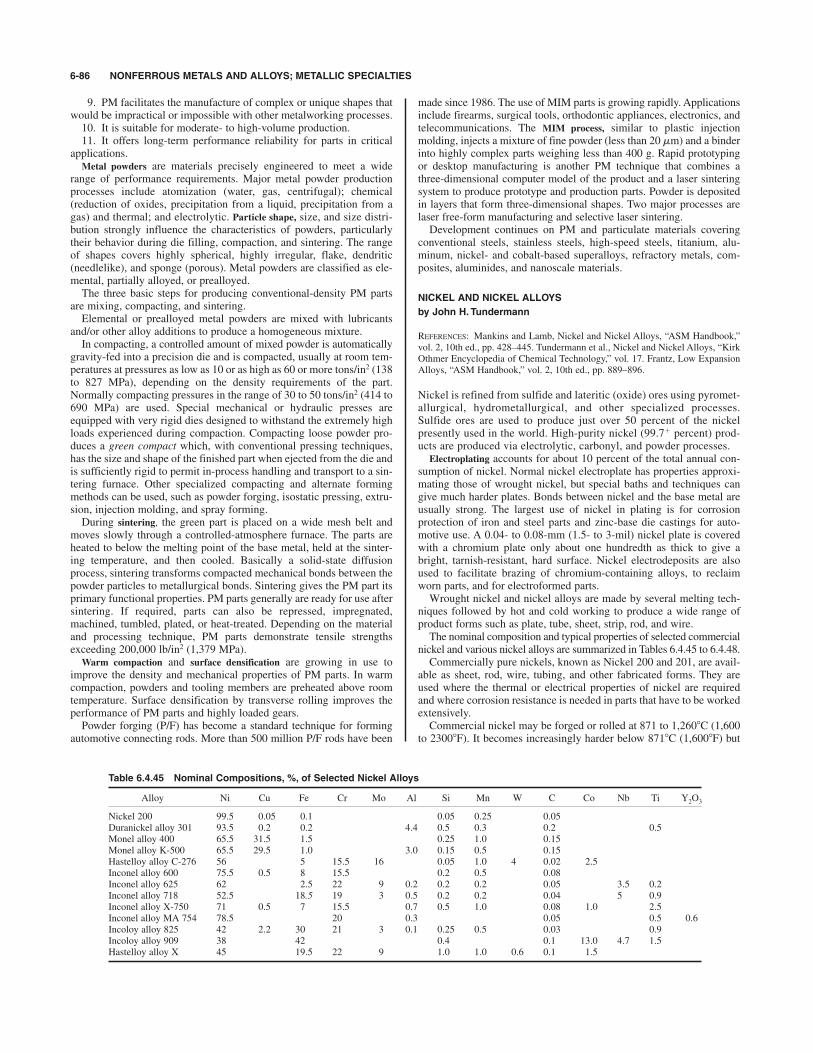
9. PM facilitates the manufacture of complex or unique shapes thatwould be impractical or impossible with other metalworking processes.10. It is suitable for moderate- to high-volume production.11. It offers long-term performance reliability for parts in critical
applications.Metal powders are materials precisely engineered to meet a wide
range of performance requirements. Major metal powder productionprocesses include atomization (water, gas, centrifugal); chemical(reduction of oxides, precipitation from a liquid, precipitation from agas) and thermal; and electrolytic. Particle shape, size, and size distri-bution strongly influence the characteristics of powders, particularlytheir behavior during die filling, compaction, and sintering. The rangeof shapes covers highly spherical, highly irregular, flake, dendritic(needlelike), and sponge (porous). Metal powders are classified as ele-mental, partially alloyed, or prealloyed.The three basic steps for producing conventional-density PM parts
are mixing, compacting, and sintering.Elemental or prealloyed metal powders are mixed with lubricants
and/or other alloy additions to produce a homogeneous mixture.In compacting, a controlled amount of mixed powder is automatically
gravity-fed into a precision die and is compacted, usually at room tem-peratures at pressures as low as 10 or as high as 60 or more tons/in2 (138to 827 MPa), depending on the density requirements of the part.Normally compacting pressures in the range of 30 to 50 tons/in2 (414 to690 MPa) are used. Special mechanical or hydraulic presses areequipped with very rigid dies designed to withstand the extremely highloads experienced during compaction. Compacting loose powder pro-duces a green compact which, with conventional pressing techniques,has the size and shape of the finished part when ejected from the die andis sufficiently rigid to permit in-process handling and transport to a sin-tering furnace. Other specialized compacting and alternate formingmethods can be used, such as powder forging, isostatic pressing, extru-sion, injection molding, and spray forming.During sintering, the green part is placed on a wide mesh belt and
moves slowly through a controlled-atmosphere furnace. The parts areheated to below the melting point of the base metal, held at the sinter-ing temperature, and then cooled. Basically a solid-state diffusionprocess, sintering transforms compacted mechanical bonds between thepowder particles to metallurgical bonds. Sintering gives the PM part itsprimary functional properties. PM parts generally are ready for use aftersintering. If required, parts can also be repressed, impregnated,machined, tumbled, plated, or heat-treated. Depending on the materialand processing technique, PM parts demonstrate tensile strengthsexceeding 200,000 lb/in2 (1,379 MPa).
Warm compaction and surface densification are growing in use toimprove the density and mechanical properties of PM parts. In warmcompaction, powders and tooling members are preheated above roomtemperature. Surface densification by transverse rolling improves theperformance of PM parts and highly loaded gears.Powder forging (P/F) has become a standard technique for forming
automotive connecting rods. More than 500 million P/F rods have been
made since 1986. The use of MIM parts is growing rapidly. Applicationsinclude firearms, surgical tools, orthodontic appliances, electronics, andtelecommunications. The MIM process, similar to plastic injectionmolding, injects a mixture of fine powder (less than 20 mm) and a binderinto highly complex parts weighing less than 400 g. Rapid prototypingor desktop manufacturing is another PM technique that combines athree-dimensional computer model of the product and a laser sinteringsystem to produce prototype and production parts. Powder is depositedin layers that form three-dimensional shapes. Two major processes arelaser free-form manufacturing and selective laser sintering.Development continues on PM and particulate materials covering
conventional steels, stainless steels, high-speed steels, titanium, alu-minum, nickel- and cobalt-based superalloys, refractory metals, com-posites, aluminides, and nanoscale materials.
NICKEL AND NICKEL ALLOYS
by John H. Tundermann
REFERENCES: Mankins and Lamb, Nickel and Nickel Alloys, “ASM Handbook,”vol. 2, 10th ed., pp. 428–445. Tundermann et al., Nickel and Nickel Alloys, “KirkOthmer Encyclopedia of Chemical Technology,” vol. 17. Frantz, Low ExpansionAlloys, “ASM Handbook,” vol. 2, 10th ed., pp. 889–896.
Nickel is refined from sulfide and lateritic (oxide) ores using pyromet-allurgical, hydrometallurgical, and other specialized processes.Sulfide ores are used to produce just over 50 percent of the nickelpresently used in the world. High-purity nickel (99.7$ percent) prod-ucts are produced via electrolytic, carbonyl, and powder processes.
Electroplating accounts for about 10 percent of the total annual con-sumption of nickel. Normal nickel electroplate has properties approxi-mating those of wrought nickel, but special baths and techniques cangive much harder plates. Bonds between nickel and the base metal areusually strong. The largest use of nickel in plating is for corrosionprotection of iron and steel parts and zinc-base die castings for auto-motive use. A 0.04- to 0.08-mm (1.5- to 3-mil) nickel plate is coveredwith a chromium plate only about one hundredth as thick to give abright, tarnish-resistant, hard surface. Nickel electrodeposits are alsoused to facilitate brazing of chromium-containing alloys, to reclaimworn parts, and for electroformed parts.Wrought nickel and nickel alloys are made by several melting tech-
niques followed by hot and cold working to produce a wide range ofproduct forms such as plate, tube, sheet, strip, rod, and wire.The nominal composition and typical properties of selected commercial
nickel and various nickel alloys are summarized in Tables 6.4.45 to 6.4.48.Commercially pure nickels, known as Nickel 200 and 201, are avail-
able as sheet, rod, wire, tubing, and other fabricated forms. They areused where the thermal or electrical properties of nickel are requiredand where corrosion resistance is needed in parts that have to be workedextensively.Commercial nickel may be forged or rolled at 871 to 1,2608C (1,600
to 23008F). It becomes increasingly harder below 8718C (1,6008F) but
6-86 NONFERROUS METALS AND ALLOYS; METALLIC SPECIALTIES
Table 6.4.45 Nominal Compositions, %, of Selected Nickel Alloys
Alloy Ni Cu Fe Cr Mo Al Si Mn W C Co Nb Ti Y2O3
Nickel 200 99.5 0.05 0.1 0.05 0.25 0.05Duranickel alloy 301 93.5 0.2 0.2 4.4 0.5 0.3 0.2 0.5Monel alloy 400 65.5 31.5 1.5 0.25 1.0 0.15Monel alloy K-500 65.5 29.5 1.0 3.0 0.15 0.5 0.15Hastelloy alloy C-276 56 5 15.5 16 0.05 1.0 4 0.02 2.5Inconel alloy 600 75.5 0.5 8 15.5 0.2 0.5 0.08Inconel alloy 625 62 2.5 22 9 0.2 0.2 0.2 0.05 3.5 0.2Inconel alloy 718 52.5 18.5 19 3 0.5 0.2 0.2 0.04 5 0.9Inconel alloy X-750 71 0.5 7 15.5 0.7 0.5 1.0 0.08 1.0 2.5Inconel alloy MA 754 78.5 20 0.3 0.05 0.5 0.6Incoloy alloy 825 42 2.2 30 21 3 0.1 0.25 0.5 0.03 0.9Incoloy alloy 909 38 42 0.4 0.1 13.0 4.7 1.5Hastelloy alloy X 45 19.5 22 9 1.0 1.0 0.6 0.1 1.5
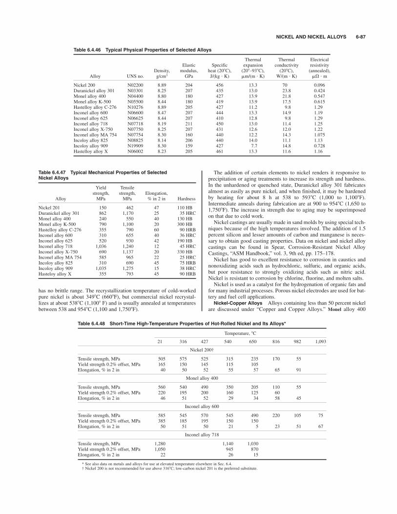
NICKEL AND NICKEL ALLOYS 6-87
has no brittle range. The recrystallization temperature of cold-workedpure nickel is about 3498C (6608F), but commercial nickel recrystal-lizes at about 5388C (1,1008 F) and is usually annealed at temperaturesbetween 538 and 9548C (1,100 and 1,7508F).
The addition of certain elements to nickel renders it responsive toprecipitation or aging treatments to increase its strength and hardness.In the unhardened or quenched state, Duranickel alloy 301 fabricatesalmost as easily as pure nickel, and when finished, it may be hardenedby heating for about 8 h at 538 to 5938C (1,000 to 1,1008F).Intermediate anneals during fabrication are at 900 to 9548C (1,650 to1,7508F). The increase in strength due to aging may be superimposedon that due to cold work.Nickel castings are usually made in sand molds by using special tech-
niques because of the high temperatures involved. The addition of 1.5percent silicon and lesser amounts of carbon and manganese is neces-sary to obtain good casting properties. Data on nickel and nickel alloycastings can be found in Spear, Corrosion-Resistant Nickel AlloyCastings, “ASM Handbook,” vol. 3, 9th ed, pp. 175–178.Nickel has good to excellent resistance to corrosion in caustics and
nonoxidizing acids such as hydrochloric, sulfuric, and organic acids,but poor resistance to strongly oxidizing acids such as nitric acid.Nickel is resistant to corrosion by chlorine, fluorine, and molten salts.Nickel is used as a catalyst for the hydrogenation of organic fats and
for many industrial processes. Porous nickel electrodes are used for bat-tery and fuel cell applications.Nickel-Copper Alloys Alloys containing less than 50 percent nickel
are discussed under “Copper and Copper Alloys.” Monel alloy 400
Table 6.4.46 Typical Physical Properties of Selected Alloys
Thermal Thermal ElectricalElastic Specific expansion conductivity resistivity
Density, modulus, heat (208C), (208–938C), (208C), (annealed),Alloy UNS no. g/cm3 GPa J/(kg " K) ,m/(m " K) W/(m " K) ,& " m
Nickel 200 N02200 8.89 204 456 13.3 70 0.096Duranickel alloy 301 N03301 8.25 207 435 13.0 23.8 0.424Monel alloy 400 N04400 8.80 180 427 13.9 21.8 0.547Monel alloy K-500 N05500 8.44 180 419 13.9 17.5 0.615Hastelloy alloy C-276 N10276 8.89 205 427 11.2 9.8 1.29Inconel alloy 600 N06600 8.47 207 444 13.3 14.9 1.19Inconel alloy 625 N06625 8.44 207 410 12.8 9.8 1.29Inconel alloy 718 N07718 8.19 211 450 13.0 11.4 1.25Inconel alloy X-750 N07750 8.25 207 431 12.6 12.0 1.22Inconel alloy MA 754 N07754 8.30 160 440 12.2 14.3 1.075Incoloy alloy 825 N08825 8.14 206 440 14.0 11.1 1.13Incoloy alloy 909 N19909 8.30 159 427 7.7 14.8 0.728Hastelloy alloy X N06002 8.23 205 461 13.3 11.6 1.16
Table 6.4.47 Typical Mechanical Properties of SelectedNickel Alloys
Yield Tensilestrength, strength, Elongation,
Alloy MPa MPa % in 2 in Hardness
Nickel 201 150 462 47 110 HBDuranickel alloy 301 862 1,170 25 35 HRCMonel alloy 400 240 550 40 130 HBMonel alloy K-500 790 1,100 20 300 HBHastelloy alloy C-276 355 790 60 90 HRBInconel alloy 600 310 655 40 36 HRCInconel alloy 625 520 930 42 190 HBInconel alloy 718 1,036 1,240 12 45 HRCInconel alloy X-750 690 1,137 20 330 HBInconel alloy MA 754 585 965 22 25 HRCIncoloy alloy 825 310 690 45 75 HRBIncoloy alloy 909 1,035 1,275 15 38 HRCHasteloy alloy X 355 793 45 90 HRB
Table 6.4.48 Short-Time High-Temperature Properties of Hot-Rolled Nickel and Its Alloys*
Temperature, 8C
21 316 427 540 650 816 982 1,093
Nickel 200†
Tensile strength, MPa 505 575 525 315 235 170 55Yield strength 0.2% offset, MPa 165 150 145 115 105Elongation, % in 2 in 40 50 52 55 57 65 91
Monel alloy 400
Tensile strength, MPa 560 540 490 350 205 110 55Yield strength 0.2% offset, MPa 220 195 200 160 125 60Elongation, % in 2 in 46 51 52 29 34 58 45
Inconel alloy 600
Tensile strength, MPa 585 545 570 545 490 220 105 75Yield strength 0.2% offset, MPa 385 185 195 150 150Elongation, % in 2 in 50 51 50 21 5 23 51 67
Inconel alloy 718
Tensile strength, MPa 1,280 1,140 1,030Yield strength 0.2% offset, MPa 1,050 945 870Elongation, % in 2 in 22 26 15
* See also data on metals and alloys for use at elevated temperature elsewhere in Sec. 6.4.† Nickel 200 is not recommended for use above 3168C; low-carbon nickel 201 is the preferred substitute.

(see Tables 6.4.45 to 6.4.47) is a nickel-rich alloy that combines highstrength, high ductility, and excellent resistance to corrosion. It is ahomogeneous solid-solution alloy; hence its strength can be increasedby cold working alone. In the annealed state, its tensile strength is about480 MPa (70 ksi), and this may be increased to 1,170 MPa (170 ksi) inhard-drawn wire. It is available in practically all fabricated forms. Alloy400 is hot-worked in the range 871 to 1,1778C (1,600 to 2,1508F) afterrapid heating in a reducing, sulfur-free atmosphere. It can be cold-worked in the same manner as mild steel, but requires more power. Veryheavily cold-worked alloy 400 may commence to recrystallize at 4278C(8008F), but in normal practice no softening will occur below 6498C(1,2008F). Annealing can be done for 2 to 5 h at about 7608C (1,4008F)or for 2 to 5 min at about 9408C (1,7258F). Nonscaling, sulfur-freeatmospheres are required.Because of its toughness, alloy 400 must be machined with high-
speed tools with slower cutting speeds and lighter cuts than mild steel.A special grade containing sulfur, Monel alloy 405, should be usedwhere high cutting speeds must be maintained. This alloy is essentiallythe same as the sulfur-free alloy in mechanical properties and corrosionresistance, and it can be hot-forged.The short-time tensile strengths of alloy 400 at elevated temperatures
are summarized in Table 6.4.48.The fatigue endurance limit of alloy 400 is about 240 MPa (34 ksi)
when annealed and 325 MPa (47 ksi) when hard-drawn. The action ofcorrosion during fatigue is much less drastic on alloy 400 than on steelsof equal or higher endurance limit.Alloy 400 is highly resistant to atmospheric action, seawater, steam,
foodstuffs, and many industrial chemicals. It deteriorates rapidly in thepresence of moist chlorine and ferric, stannic, or mercuric salts in acidsolutions. It must not be exposed when hot to molten metals, sulfur, orgaseous products of combustion containing sulfur.Small additions of aluminum and titanium to the alloy 400 base nickel-
copper alloy produces precipitation-hardenable Monel alloy K-500.This alloy is sufficiently ductile in the annealed state to permit drawing,forming, bending, or other cold-working operations but workhardensrapidly and requires more power than mild steel. It is hotworked at 927to 1,1778C (1,700 to 2,1508F) and should be quenched from 8718C(1,6008F) if the metal is to be further worked or hardened. Heat treat-ment consists of quenching from 8718C (1,6008F), cold working ifdesired, and reheating for 10 to 16 h at 538 to 5938C (1,000 to 1,1008F).If no cold working is intended, the quench may be omitted on sectionsless than 50 mm (2 in) thick and the alloy hardened at 5938C (1,1008F).The properties of the heat-treated alloy remain quite stable, at least upto 5388C (1,0008F). It is nonmagnetic down to %1018C (%1508F).Heat-Resistant Nickel-Chromium and Nickel-Chromium-lron Alloys
See “Metals and Alloys for Use at Elevated Temperatures” for furtherinformation on high-temperature properties of nickel alloys.The addition of chromium to nickel improves strength and corrosion
resistance at elevated temperature. Nickel chromium alloys such as 80Ni 20 Cr are extensively used in electrical resistance heating applica-tions. Typically, additions of up to 4 percent aluminum and 1 percentyttrium are made to these alloys to increase hot oxidation and corrosionresistance. Incorporating fine dispersions of inert oxides to this systemsignificantly enhances high-temperature properties and microstructuralstability. Inconel alloy MA 754, which contains 0.6 percent Y2O3,exhibits good fatigue strength and corrosion resistance at 1,1008C(2,0108F) and is used in gas-turbine engines and other extreme serviceapplications.Inconel alloy 600 is a nickel-chromium-iron alloy. Alloy 600 is a
high-strength nonmagnetic [at %408C (%408F)] alloy which is usedwidely for corrosion- and heat-resisting applications at temperatures upto 1,2048C (2,2008F) in sulfidizing atmospheres. In sulfidizing atmos-pheres, the maximum recommended temperature is 8168C (1,5008F).Inconel alloy X-750 is an age-hardenable modification suitable forstressed applications at temperatures up to 649 to 8168C (1,200 to1,5008F). The addition of molybdenum to this system provides alloys,e.g., Hastelloy alloy X, with additional solid-solution strengthening andgood oxidation resistance up to 1,2008C (2,2008F).
The combination of useful strength and oxidation resistance makesnickel alloys frequent choices for high-temperature service. Table 6.4.48indicates the changes in mechanical properties with temperature.Corrosion-Resistant Nickel-Molybdenum and Nickel-lron-Chromium
Alloys A series of solid-solution nickel alloys containing molybde-num exhibit superior resistance to corrosion by hot concentrated acidssuch as hydrochloric, sulfuric, and nitric acids. Hastelloy alloy C-276,which also contains chromium, tungsten, and cobalt, is resistant to awide range of chemical process environments including strong oxi-dizing acids, chloride solutions, and other acids and salts. Incoloyalloy 825, a nickel-iron-chromium alloy with additions of molybde-num, is especially resistant to sulfuric and phosphoric acids. Thesealloys are used in pollution control, chemical processing, acid pro-duction, pulp and paper production, waste treatment, and oil and gasapplications. Although these types of alloys are used extensively inaqueous environments, they also have good elevated-temperatureproperties.Nickel-lron Alloys Nickel is slightly ferromagnetic but loses its
magnetism at a temperature of 3688C (6958F) when pure. For commer-cial nickel, this temperature is about 3438C (6508F). Monel alloy 400 islightly magnetic and loses all ferromagnetism above 938C (2008F). Thedegree of ferromagnetism and the temperature at which ferromagnetismis lost are very sensitive to variations in composition and mechanicaland thermal treatments.An important group of soft magnetic alloys is the nickel irons and
their modifications, which exhibit high initial permeability, high maxi-mum magnetization, and low residual magnetization. Nickel-iron alloysalso exhibit low coefficients of thermal expansion that closely matchthose of many glasses and are therefore often used for glass-sealingapplications. Nickel-iron alloys such as Incoloy alloy 909, which con-tains cobalt, niobium, and titanium, have found wide applications ingas-turbine and rocket engines, springs and instruments, and as con-trolled-expansion alloys designed to provide high strength and lowcoefficients of thermal expansion up to 6508C (1,2008F).Low-Temperature Properties of Nickel Alloys Several nickel-base
alloys have very good properties at low temperatures, in contrast to fer-rous alloys whose impact strength (the index of brittleness) falls offvery rapidly with decreasing temperature. The impact strength remainsnearly constant with most nickel-rich alloys, while the tensile and yieldstrengths increase as they do in the other alloys. Specific data onlowtemperature properties may be found in White and Siebert,“Literature Survey of Low-Temperature Properties of Metals,”Edwards, and “Mechanical Properties of Metals at Low Temperatures,”NBS Circ. 520, 1952.Welding Alloys Nickel alloys can be welded with similar-composi-
tion welding materials and basic welding processes such as gas tungstenarc welding (GTAW), gas metal arc welding (GMAW), shielded metalarc welding (SMAW), brazing, and soldering. The procedures used aresimilar to those for stainless steels. Nickel-base welding products arealso used to weld dissimilar materials. Nickel-base filler metals, espe-cially with high molybdenum contents, are typically used to weld otheralloys to ensure adequate pitting and crevice corrosion resistance infinal weld deposits. Nickel and nickel iron welding electrodes are usedto weld cast irons.(Note: Inconel, Incoloy, and Monel are trademarks of the Inco family
of companies. Hastelloy is a trademark of Haynes International.)
TITANIUM AND ZIRCONIUM
by John R. Schley
REFERENCES: Donachie, “Titanium, A Technical Guide,” ASM International,Metals Park, OH. “Titnanium, The Choice,” rev. 1990, Titanium DevelopmentAssociation, Boulder, CO. ASM Metals Handbook, “Corrosion,” vol. 13, 1987edition, ASM International, Metals Park, OH. Schemel, “ASTM Manual onZirconium and Hafnium,” ASTM STP-639, Philadelphia, PA. “Corrosion ofZirconium Alloys,” ASTM STP 368, Philadelphia. “Zircadyne Properties andApplications,” Teledyne Wah Chang Albany, Albany, OR. “Basic Design Factsabout Titanium,” RMI Titanium Company, Niles, OH.
6-88 NONFERROUS METALS AND ALLOYS; METALLIC SPECIALTIES
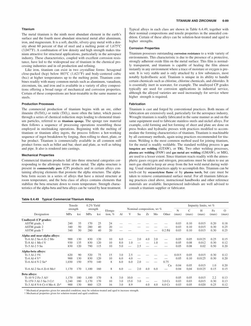
TITANIUM AND ZIRCONIUM 6-89
Titanium
The metal titanium is the ninth most abundant element in the earth’ssurface and the fourth most abundant structural metal after aluminum,iron, and magnesium. It is a soft, ductile, silvery-gray metal with a den-sity about 60 percent of that of steel and a melting point of 1,6758C(3,0478F). A combination of low density and high strength makes tita-nium attractive for structural applications, particularly in the aerospaceindustry. These characteristics, coupled with excellent corrosion resis-tance, have led to the widespread use of titanium in the chemical pro-cessing industries and in oil production and refining.Like iron, titanium can exist in two crystalline forms: hexagonal
close-packed (hcp) below 8838C (1,6218F) and body-centered cubic(bcc) at higher temperatures up to the melting point. Titanium com-bines readily with many common metals such as aluminum, vanadium,zirconium, tin, and iron and is available in a variety of alloy composi-tions offering a broad range of mechanical and corrosion properties.Certain of these compositions are heat-treatable in the same manner assteels.
Production Processes
The commercial production of titanium begins with an ore, eitherilmenite (FeTiO3) or rutile (TiO2), more often the latter, which passesthrough a series of chemical reduction steps leading to elemental titani-um particles, referred to as titanium sponge. The sponge raw materialthen follows a sequence of processing operations resembling thoseemployed in steelmaking operations. Beginning with the melting oftitanium or titanium alloy ingots, the process follows a hot-workingsequence of ingot breakdown by forging, then rolling to sheet, plate, orbar product. Titanium is commercially available in all common millproduct forms such as billet and bar, sheet and plate, as well as tubingand pipe. It also is rendered into castings.
Mechanical Properties
Commercial titanium products fall into three structural categories cor-responding to the allotropic forms of the metal. The alpha structure ispresent in commercially pure (CP) products and in certain alloys con-taining alloying elements that promote the alpha structure. The alpha-beta form occurs in a series of alloys that have a mixed structure atroom temperature, and the beta class of alloys contains elements thatstabilize the beta structure down to room temperature. Strength charac-teristics of the alpha-beta and beta alloys can be varied by heat treatment.
Typical alloys in each class are shown in Table 6.4.49, together withtheir nominal compositions and tensile properties in the annealed con-dition. Certain of these alloys can be solution-heat-treated and aged tohigher strengths.
Corrosion Properties
Titanium possesses outstanding corrosion resistance to a wide variety ofenvironments. This characteristic is due to the presence of a protective,strongly adherent oxide film on the metal surface. This film is normal-ly transparent, and titanium is capable of healing the film almostinstantly in any environment where a trace of moisture or oxygen is pre-sent. It is very stable and is only attacked by a few substances, mostnotably hydrofluoric acid. Titanium is unique in its ability to handlecertain chemicals such as chlorine, chlorine chemicals, and chlorides. Itis essentially inert in seawater, for example. The unalloyed CP gradestypically are used for corrosion applications in industrial service,although the alloyed varieties are used increasingly for service wherehigher strength is required.
Fabrication
Titanium is cast and forged by conventional practices. Both means offabrication are extensively used, particularly for the aerospace industry.Wrought titanium is readily fabricated in the same manner as and on thesame equipment used to fabricate stainless steels and nickel alloys. Forexample, cold forming and hot forming of sheet and plate are done onpress brakes and hydraulic presses with practices modified to accom-modate the forming characteristics of titanium. Titanium is machinableby all customary methods, again using practices recommended for tita-nium. Welding is the most common method used for joining titanium,for the metal is readily weldable. The standard welding process is gastungsten arc welding (GTAW), or TIG. Two other welding processes,plasma arc welding (PAW) and gas metal arc welding (GMAW), or MIG,are used to a lesser extent. Since titanium reacts readily with the atmos-pheric gases oxygen and nitrogen, precautions must be taken to use aninert-gas shield to keep air away from the hot weld metal during weld-ing. Usual standard practices apply to accomplish this. Titanium can betorch-cut by oxyacetylene flame or by plasma torch, but care must betaken to remove contaminated surface metal. For all titanium fabricat-ing practices cited above, instructional handbooks and other referencematerials are available. Inexperienced individuals are well advised toconsult a titanium supplier or fabricator.
Table 6.4.49 Typical Commercial Titanium Alloys
Tensile 0.2% Yield Impurity limits, wt %strength strength
Elonga-Nominal composition, wt %
N C H Fe ODesignation MPa ksi MPa ksi tion, % Al V Sn Zr Mo Other (max) (max) (max) (max) (max)
Unalloyed (CP grades:
ASTM grade, 1 240 35 170 25 24 — — — — — — 0.03 0.10 0.015 0.20 0.18ASTM grade 2 340 50 280 40 20 — — — — — 0.03 0.10 0.015 0.30 0.25ASTM grade 7 340 50 280 40 20 — — — — 0.2 Pd 0.03 0.10 0.015 0.30 0.25
Alpha and near-alpha alloys:
Ti-6 Al-2 Sn-4 Zr-2 Mo 900 130 830 120 10 6.0 — 2.0 4.0 2.0 — 0.05 0.05 0.0125 0.25 0.15Ti-8 Al-1 Mo-l V 930 135 830 120 10 8.0 1.0 — — 1.0 — 0.05 0.08 0.012 0.30 0.12Ti-5 Al-2 5 Sn 830 120 790 115 10 5.0 — 2.5 — — — 0.05 0.08 0.02 0.50 0.20
Alpha-beta alloys:
Ti-3 Al-2 5V. 620 90 520 75 15 3.0 2.5 — — — — 0.015 0.05 0.015 0.30 0.12Ti-6 Al-4 V* 900 130 830 120 10 6.0 4.0 — — — 0.05 0.10 0.0125 0:30 0.20Ti-6 Al-6 V-2 Sn* 1,030 150 .970 140 8 6.0 6.0 2.0 — — 0.75
Cu 0.04 0.05 0.015 1.0 0.20Ti-6 Al-2 Sn-4 Zr-6 Mo† 1,170 170 1,100 160 8 6.0 — 2.0 4.0 6.0 — 0.04 0,04 0.0125 0.15 0.15
Beta alloys:
Ti-10 V-2 Fe-3 Al† 1,170 180 1,100 170 8 3.0 10.0 — — 0.05 0.05 0.015 2.2 0.13Ti-15V-3 Al-3 Sn-3 Cr† 1,240 180 1,170 170 10 3.0 15.0 3.0 — — 3.0 Cr 0.03 0.03 0,015 0.30 0.13Ti-3 Al-8 V-6 Cr-4 Mo-4. Zr* 900 130 860 125 16 3.0 8.9 4.0 4.0 6.0 Cr 0.03 0.05 0.020 0.25 0.12
* Mechanical properties given for annealed condition; may be solution-treated and aged to increase strength.† Mechanical properties given for solution-treated and aged condition.
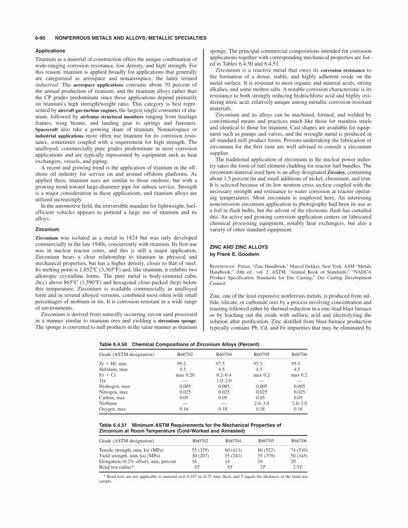
Applications
Titanium as a material of construction offers the unique combination ofwide-ranging corrosion resistance, low density, and high strength. Forthis reason, titanium is applied broadly for applications that generallyare categorized as aerospace and nonaerospace, the latter termedindustrial. The aerospace applications consume about 70 percent ofthe annual production of titanium, and the titanium alloys rather thanthe CP grades predominate since these applications depend primarilyon titanium’s high strength/weight ratio. This category is best repre-sented by aircraft gas-turbine engines, the largest single consumer of tita-nium, followed by airframe structural members ranging from fuselageframes, wing beams, and landing gear to springs and fasteners.Spacecraft also take a growing share of titanium. Nonaerospace orindustrial applications more often use titanium for its corrosion resis-tance, sometimes coupled with a requirement for high strength. Theunalloyed, commercially pure grades predominate in most corrosionapplications and are typically represented by equipment such as heatexchangers, vessels, and piping.A recent and growing trend is the application of titanium in the off-
shore oil industry for service on and around offshore platforms. Asapplied there, titanium uses are similar to those onshore, but with agrowing trend toward large-diameter pipe for subsea service. Strengthis a major consideration in these applications, and titanium alloys areutilized increasingly.In the automotive field, the irreversible mandate for lightweight, fuel-
efficient vehicles appears to portend a large use of titanium and itsalloys.
Zirconium
Zirconium was isolated as a metal in 1824 but was only developedcommercially in the late 1940s, concurrently with titanium. Its first usewas in nuclear reactor cores, and this is still a major application.Zirconium bears a close relationship to titanium in physical andmechanical properties, but has a higher density, closer to that of steel.Its melting point is 1,8528C (3,3658F) and, like titanium, it exhibits twoallotropic crystalline forms. The pure metal is body-centered cubic(bcc) above 8658C (1,5908F) and hexagonal close-packed (hcp) belowthis temperature. Zirconium is available commercially in unalloyedform and in several alloyed versions, combined most often with smallpercentages of niobium or tin. It is corrosion-resistant in a wide rangeof environments.Zirconium is derived from naturally occurring zircon sand processed
in a manner similar to titanium ores and yielding a zirconium sponge.
The sponge is converted to mill products in the same manner as titanium
sponge. The principal commercial compositions intended for corrosionapplications together with corresponding mechanical properties are list-ed in Tables 6.4.50 and 6.4.51.Zirconium is a reactive metal that owes its corrosion resistance to
the formation of a dense, stable, and highly adherent oxide on themetal surface. It is resistant to most organic and mineral acids, strongalkalies, and some molten salts. A notable corrosion characteristic is itsresistance to both strongly reducing hydrochloric acid and highly oxi-dizing nitric acid, relatively unique among metallic corrosion-resistantmaterials.Zirconium and its alloys can be machined, formed, and welded by
conventional means and practices much like those for stainless steelsand identical to those for titanium. Cast shapes are available for equip-ment such as pumps and valves, and the wrought metal is produced inall standard mill product forms. Persons undertaking the fabrication ofzirconium for the first time are well advised to consult a zirconiumsupplier.The traditional application of zirconium in the nuclear power indus-
try takes the form of fuel element cladding for reactor fuel bundles. Thezirconium material used here is an alloy designated Zircaloy, containingabout 1.5 percent tin and small additions of nickel, chromium, and iron.It is selected because of its low neutron cross section coupled with thenecessary strength and resistance to water corrosion at reactor operat-ing temperatures. Most zirconium is employed here. An interestingnoncorrosion zirconium application in photography had been its use asa foil in flash bulbs, but the advent of the electronic flash has curtailedthis. An active and growing corrosion application centers on fabricatedchemical processing equipment, notably heat exchangers, but also avariety of other standard equipment.
ZINC AND ZINC ALLOYS
by Frank E. Goodwin
REFERENCES: Porter, “Zinc Handbook,” Marcel Dekker, New York. ASM “MetalsHandbook,” 10th ed., vol. 2. ASTM, “Annual Book of Standards.” “NADCAProduct Specification Standards for Die Casting,” Die Casting DevelopmentCouncil.
Zinc, one of the least expensive nonferrous metals, is produced from sul-fide, silicate, or carbonate ores by a process involving concentration androasting followed either by thermal reduction in a zinc-lead blast furnaceor by leaching out the oxide with sulfuric acid and electrolyzing thesolution after purification. Zinc distilled from blast-furnace productiontypically contains Pb, Cd, and Fe impurities that may be eliminated by
6-90 NONFERROUS METALS AND ALLOYS; METALLIC SPECIALTIES
Table 6.4.50 Chemical Compositions of Zirconium Alloys (Percent)
Grade (ASTM designation) R60702 R60704 R60705 R60706
Zr $ Hf, min 99.2 97.5 95.5 95.5Hafnium, max 4.5 4.5 4.5 4.5Fe $ Cr max 0.20 0.2–0.4 max 0.2 max 0.2Tin — 1.0–2.0 — —Hydrogen, max 0.005 0.005 0.005 0.005Nitrogen, max 0.025 0.025 0.025 0.025Carbon, max 0.05 0.05 0.05 0.05Niobium — — 2.0–3.0 2.0–3.0Oxygen, max 0.16 0.18 0.18 0.16
Table 6.4.51 Minimum ASTM Requirements for the Mechanical Properties ofZirconium at Room Temperature (Cold-Worked and Annealed)
Grade (ASTM designation) R60702 R60704 R60705 R60706
Tensile strength, min, ksi (MPa) 55 (379) 60 (413) 80 (552) 74 (510)Yield strength, min, ksi (MPa) 30 (207) 35 (241) 55 (379) 50 (345)Elongation (0.2% offset), min, percent 16 14 16 20Bend test radius* 5T 5T 3T 2.5T
* Bend tests are not applicable to material over 0.187 in (4.75 mm) thick, and T equals the thickness of the bend testsample.
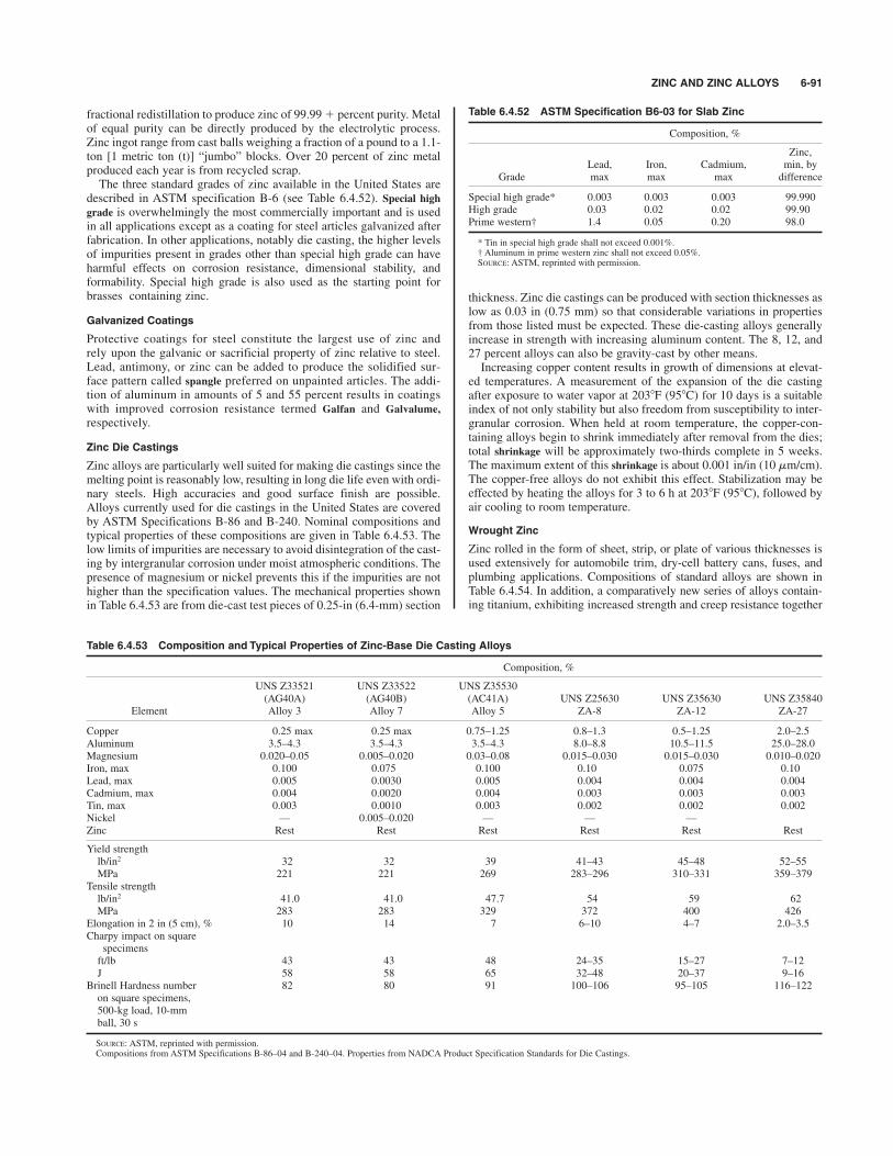
ZINC AND ZINC ALLOYS 6-91
fractional redistillation to produce zinc of 99.99 $ percent purity. Metalof equal purity can be directly produced by the electrolytic process.Zinc ingot range from cast balls weighing a fraction of a pound to a 1.1-ton [1 metric ton (t)] “jumbo” blocks. Over 20 percent of zinc metalproduced each year is from recycled scrap.The three standard grades of zinc available in the United States are
described in ASTM specification B-6 (see Table 6.4.52). Special highgrade is overwhelmingly the most commercially important and is usedin all applications except as a coating for steel articles galvanized afterfabrication. In other applications, notably die casting, the higher levelsof impurities present in grades other than special high grade can haveharmful effects on corrosion resistance, dimensional stability, andformability. Special high grade is also used as the starting point forbrasses containing zinc.
Galvanized Coatings
Protective coatings for steel constitute the largest use of zinc andrely upon the galvanic or sacrificial property of zinc relative to steel.Lead, antimony, or zinc can be added to produce the solidified sur-face pattern called spangle preferred on unpainted articles. The addi-tion of aluminum in amounts of 5 and 55 percent results in coatingswith improved corrosion resistance termed Galfan and Galvalume,
respectively.
Zinc Die Castings
Zinc alloys are particularly well suited for making die castings since themelting point is reasonably low, resulting in long die life even with ordi-nary steels. High accuracies and good surface finish are possible.Alloys currently used for die castings in the United States are coveredby ASTM Specifications B-86 and B-240. Nominal compositions andtypical properties of these compositions are given in Table 6.4.53. Thelow limits of impurities are necessary to avoid disintegration of the cast-ing by intergranular corrosion under moist atmospheric conditions. Thepresence of magnesium or nickel prevents this if the impurities are nothigher than the specification values. The mechanical properties shownin Table 6.4.53 are from die-cast test pieces of 0.25-in (6.4-mm) section
thickness. Zinc die castings can be produced with section thicknesses aslow as 0.03 in (0.75 mm) so that considerable variations in propertiesfrom those listed must be expected. These die-casting alloys generallyincrease in strength with increasing aluminum content. The 8, 12, and27 percent alloys can also be gravity-cast by other means.Increasing copper content results in growth of dimensions at elevat-
ed temperatures. A measurement of the expansion of the die castingafter exposure to water vapor at 2038F (958C) for 10 days is a suitableindex of not only stability but also freedom from susceptibility to inter-granular corrosion. When held at room temperature, the copper-con-taining alloys begin to shrink immediately after removal from the dies;total shrinkage will be approximately two-thirds complete in 5 weeks.The maximum extent of this shrinkage is about 0.001 in/in (10 mm/cm).The copper-free alloys do not exhibit this effect. Stabilization may beeffected by heating the alloys for 3 to 6 h at 2038F (958C), followed byair cooling to room temperature.
Wrought Zinc
Zinc rolled in the form of sheet, strip, or plate of various thicknesses isused extensively for automobile trim, dry-cell battery cans, fuses, andplumbing applications. Compositions of standard alloys are shown inTable 6.4.54. In addition, a comparatively new series of alloys contain-ing titanium, exhibiting increased strength and creep resistance together
Table 6.4.52 ASTM Specification B6-03 for Slab Zinc
Composition, %
Zinc,Lead, Iron, Cadmium, min, by
Grade max max max difference
Special high grade* 0.003 0.003 0.003 99.990High grade 0.03 0.02 0.02 99.90Prime western† 1.4 0.05 0.20 98.0
* Tin in special high grade shall not exceed 0.001%.† Aluminum in prime western zinc shall not exceed 0.05%.SOURCE: ASTM, reprinted with permission.
Table 6.4.53 Composition and Typical Properties of Zinc-Base Die Casting Alloys
Composition, %
UNS Z33521 UNS Z33522 UNS Z35530(AG40A) (AG40B) (AC41A) UNS Z25630 UNS Z35630 UNS Z35840
Element Alloy 3 Alloy 7 Alloy 5 ZA-8 ZA-12 ZA-27
Copper 0.25 max 0.25 max 0.75–1.25 0.8–1.3 0.5–1.25 2.0–2.5Aluminum 3.5–4.3 3.5–4.3 3.5–4.3 8.0–8.8 10.5–11.5 25.0–28.0Magnesium 0.020–0.05 0.005–0.020 0.03–0.08 0.015–0.030 0.015–0.030 0.010–0.020Iron, max 0.100 0.075 0.100 0.10 0.075 0.10Lead, max 0.005 0.0030 0.005 0.004 0.004 0.004Cadmium, max 0.004 0.0020 0.004 0.003 0.003 0.003Tin, max 0.003 0.0010 0.003 0.002 0.002 0.002Nickel — 0.005–0.020 — — —Zinc Rest Rest Rest Rest Rest Rest
Yield strengthlb/in2 32 32 39 41–43 45–48 52–55MPa 221 221 269 283–296 310–331 359–379
Tensile strengthlb/in2 41.0 41.0 47.7 54 59 62MPa 283 283 329 372 400 426
Elongation in 2 in (5 cm), % 10 14 7 6–10 4–7 2.0–3.5Charpy impact on square
specimensft/lb 43 43 48 24–35 15–27 7–12J 58 58 65 32–48 20–37 9–16
Brinell Hardness number 82 80 91 100–106 95–105 116–122on square specimens,500-kg load, 10-mmball, 30 s
SOURCE: ASTM, reprinted with permission.Compositions from ASTM Specifications B-86–04 and B-240–04. Properties from NADCA Product Specification Standards for Die Castings.

with low thermal expansion, has become popular in Europe. A typicalanalysis is 0.5 to 0.8 percent Cu, 0.08 to 0.16 percent Ti, and maximumvalues of 0.2 percent Pb, 0.015 percent Fe, 0.01 percent Cd, 0.01 per-cent Mn, and 0.02 percent Cr. All alloys are produced by hot rolling fol-lowed by cold rolling when some stiffness and temper are required.Deep-drawing or forming operations are carried out on the softergrades, while limited forming to produce architectural items, plumbing,and automotive trim can be carried out using the harder grades.Alloys containing 0.65 to 1.025 percent Cu are significantly stronger
than unalloyed zinc and can be work-hardened. Since 1982, the UnitedStates one-cent coin has been made from a zinc-copper alloy that iscopper-plated before coining. The addition of 0.01 percent Mg allowsdesign stresses up to 10,000 lb/in2 (69 MPa). The Zn-Cu-Ti alloy ismuch stronger, with a typical tensile strength of 25,000 lb/in2 (172 MPa).
Rolled zinc may be easily formed by all standard techniques. Thedeformation behavior of rolled zinc and its alloys varies with direction;its crystal structure renders it nonisotropic. In spite of this, it can beformed into parts similar to those made of copper, aluminum, and brass,and usually with the same tools, provided the temperature is not below
708F (218C). More severe operations can best be performed at temper-atures up to 1258F (528C). When a cupping operation is performed, atake-in of 40 percent on the first draw is usual. Warm, soapy water iswidely used as a lubricant. The soft grades are self-annealing at roomtemperature, but harder grades respond to deformation better if they areannealed between operations. The copper-free zincs are annealed at2128F (1008C) and the zinc-copper alloys at 4408C (2208C). Welding ispossible with a wire of composition similar to the base metals.Soldering with typical tin-lead alloys is exceptionally easy. The impactextrusion process is widely used for producing battery cups and similararticles.
Effect of Temperature
Properties of zinc and zinc alloys are very sensitive to temperature. Creep
resistance decreases with increasing temperature, and this must be consid-ered in designing articles to withstand continuous load. When steel screwsare used to fasten zinc die castings, maximum long-term clamping loadwill be reached if an engagement length 4 times the diameter of the screwis used along with cut (rather than rolled) threads on the fasteners.
6-92 CORROSION
Table 6.4.54 Typical Composition of Rolled Zinc (ASTM Specification B69–01), %
Lead Iron, max Cadmium Copper Magnesium Zinc
0.05 max 0.010 0.005 max 0.001 max — Remainder0.05–0.12 0.012 0.005 max 0.001 max — Remainder0.30–0.65 0.020 0.20–0.35 0.005 max — Remainder0.05–0.12 0.012 0.005 max 0.65–1.25 — Remainder0.05–0.12 0.015 0.005 max 0.75–1.25 0.007–0.02 Remainder
SOURCE: ASTM, reprinted with permission.
6.5 CORROSIONby Robert D. Bartholomew and David A. Shifler
REFERENCES: Uhlig, “The Corrosion Handbook,” Wiley, New York, 1948. R. Winston Revie (ed.) “Uhlig’s Corrosion Handbook,” 2d ed., Wiley Interscience,New York, 2000. Evans, “An Introduction to Metallic Corrosion,” 3d ed., EdwardArnold & ASM International, Metals Park, OH, 1981. Van Delinder (ed.),“Corrosion Basics—An Introduction,” 2d ed., NACE International, Houston, TX,1984. Wranglen, “An Introduction to Corrosion and Protection of Metals,”Chapman & Hall, London, 1986. Fontana, “Corrosion Engineering,” 3d ed.,McGraw-Hill, New York, 1986. Jones, “Principles and Prevention of Corrosion,”Macmillan, New York, 1992. Jones, “Principles and Prevention of Corrosion,” 2d ed.,Prentice-Hall, Upper Saddle River, NJ, 1996. Scully, “The Fundamentals ofCorrosion” 3d ed., Pergamon, New York, 1990. Kaesche, “Metallic Corrosion,”2d ed., Rapp (trans.), NACE International, Houston, TX, 1985. Sheir (ed.),“Corrosion,” 2d ed., Newnes-Butterworths, London, 1976. Sheir and Jarman.(eds.), “Corrosion,” 3d ed., Butterworth-Heinemann, Oxford, 1994. “Corrosion,”vol. 13, “Metals Handbook,” 9th ed., ASM International, Metals Park, OH, 1987.Cramer and Covino (eds.), “Corrosion: Fundamentals, Testing, and Protection,”ASM International, Materials park, OH, 2003. Gellings, “Introduction toCorrosion Prevention and Control,” Delft University Press, Delft, TheNetherlands, 1985. Sedriks, “Corrosion of Stainless Steels,” 2d ed., WileyInterscience, New York, 1996. Pourbaix, “Atlas of Electrochemical Equilibria inAqueous Solutions,” NACE International, Houston, TX, 1974. Prentice,“Electrochemical Engineering Principles,” Prentice-Hall, Englewoods Cliffs, NJ,1991. Newman, and Thomas-Alyea, “Electrochemical Systems,” 3d ed., WileyInterscience, New York, 2004. Bockris and Reddy, “Modern Electrochemistry,”Plenum, New York, 1970. Bockris and Khan, “Surface Electrochemistry—AMolecular Level Approach,” Plenum, New York, 1993.
INTRODUCTION
Corrosion is the deterioration of a material or its properties because ofits reaction with the environment. Materials may include metals and
alloys, nonmetals, woods, ceramics, plastics, composites, etc. Althoughcorrosion as a science is barely 150 years old, its effects have impactedhumankind for thousands of years. The importance of understandingthe causes, initiation, and propagation of corrosion and the methods forcontrolling its degradation is threefold. First, corrosion generates aneconomic impact through materials losses and failures of various struc-tures and components. A recent study estimated that the combinedannualized economic losses from 1999 to 2001 in the United Statesfrom corrosion was $276 billion (Payer, et al., “Corrosion Costs andPreventative Strategies in the United States,” Publication no. FHWA-RD-01-156, U.S. Federal Highway Administration, 2001; Cost ofCorrosion Study Unveiled, Mater. Perf., supplement, NACEInternational, July 2002). Studies of corrosion costs in other countrieshave determined that 3 to 4 percent of GNP is related to economic lossesfrom corrosion. These estimates consider only the direct economiccosts. Indirect costs are difficult to assess but can include plant down-time, loss of products or services, loss of efficiency, contamination, andoverdesign of structures and components. Application of current corro-sion control technology (discussed later) could recover or avoid 15 to20 percent of the costs due to corrosion.Second, an improved consideration of corrosion prevention or con-
trol is improved safety. Catastrophic degradation and failures of pres-sure vessels, petrochemical plants, boilers, aircraft sections, tankscontaining toxic materials, and automotive parts have led to thousandsof personal injuries and death, which often result in subsequent litiga-tion. If the safety of individual workers or the public is endangered insome manner by selection of a material or use of a corrosion controlmethod, that approach should be abandoned. Once assurance is given
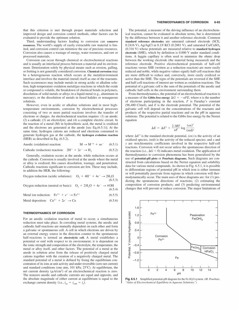
THERMODYNAMICS OF CORROSION 6-93
that this criterion is met through proper materials selection andimproved design and corrosion control methods, other factors can beevaluated to provide the optimum solution.Third, understanding factors leading to corrosion can conserve
resources. The world’s supply of easily extractable raw material is lim-ited, and corrosion control can minimize the use of precious resources.Corrosion also causes a wastage of energy, water resources, and raw orprocessed materials.Corrosion can occur through chemical or electrochemical reactions
and is usually an interfacial process between a material and its environ-ment. Deterioration solely by physical means such as erosion, galling,or fretting is not generally considered corrosion. Chemical corrosionmaybe a heterogeneous reaction which occurs at the metal/environmentinterface and involves the material (metal) itself as one of the reactants.Such occurrences may include metals in strong acidic or alkaline solu-tion, high-temperature oxidation metal/gas reactions in which the oxideor compound is volatile, the breakdown of chemical bonds in polymers,dissolution of solid metals or alloys in a liquid metal (e.g., aluminum inmercury), or the dissolution of metals in fused halides or nonaqueoussolutions.However, even in acidic or alkaline solutions and in most high-
temperature environments, corrosion by electrochemical processesconsisting of two or more partial reactions involves the transfer ofelectrons or charges. An electrochemical reaction requires: (1) an anode;(2) a cathode; (3) an electrolyte; and (4) a complete electric circuit. Inthe reaction of a metal (M) in hydrochloric acid, the metal is oxidizedand the electrons are generated at the anode [sec Eq.(6.5.1)]. At thesame time, hydrogen cations are reduced and electrons consumed togenerate hydrogen gas at the cathode, the hydrogen evolution reaction(HER) as described in Eq. (6.5.2).
Anodic (oxidation) reaction: (6.5.1)
Cathodic (reduction) reaction: (6.5.2)
Generally, oxidation occurs at the anode, while reduction occurs atthe cathode. Corrosion is usually involved at the anode where the metalor alloy is oxidized; this causes dissolution, wastage, and penetration.Cathodic reactions significant to corrosion are few. These may include,in addition the HER, the following:
Oxygen reduction (acidic solutions):(6.5.3)
Oxygen reduction (neutral or basic):(6.5.4)
Metal ion reduction: (6.5.5)
Metal deposition: (6.5.6)
THERMODYNAMICS OF CORROSION
For an anodic oxidation reaction of metal to occur, a simultaneousreduction must take place. In corroding metal systems, the anodic andcathodic half-reactions are mutually dependent on each other and forma galvanic or spontaneous cell. A cell in which electrons are driven byan external energy source in the direction counter to the spontaneoushalf-reactions is termed an electrolytic cell. A metal establishes apotential or emf with respect to its environment; it is dependent onthe ionic strength and composition of the electrolyte, the temperature, themetal or alloy itself, and other factors. The potential of a metal at theanode in solution arise from the release of positively charged metalcations together with the creation of a negatively charged metal. Thestandard potential of a metal is defined by fixing the equilibrium con-centration of its ions at unit activity and under reversible (zero net current)and standard conditions (one atm, 101 kPa; ). At equilibrium, thenet current density (mA/cm2) of an electrochemical reaction is zero.The nonzero anodic and cathodic currents are equal and opposite, andthe absolute magnitude of either current at equilibrium is equal to theexchange current density si.e., ian 5 icath 5 iod.
258C
Cu21 1 2e2S Cu
Fe31 1 e2S Fe21
O2 1 2 H2O 1 4e2S 4 OH
O2 1 4H1 1 4e2S 2H2O
2H1 1 2e2S H2
M S M1n 1 ne2
The potential, a measure of the driving influence of an electrochem-ical reaction, cannot be evaluated in absolute terms, but is determinedby the difference between it and another reference electrode. Commonstandard reference electrodes are saturated calomel electrode (SCE,0.2416 V), Ag/AgCl in 0.1N KCl (0.2881 V), and saturated Cu/CuSO4
(0.316 V) whose potentials are measured relative to standard hydrogenelectrode (SHE), which by definition is 0.000 V under standard condi-tions. A luggin capillary is often used to minimize the ohmic dropbetween the working electrode (the material being measured) and thereference electrode. Positive electrochemical potentials of half-cellreactions versus SHE (written as a reduction reaction) are more easilyreduced and noble, while negative values signify half-cell reactions thatare more difficult to reduce and, conversely, more easily oxidized oractive than the SHE. The signs of the potentials are reversed if the SHEand half-cell reactions of interest are written as oxidation reactions. Thepotential of a galvanic cell is the sum of the potentials of the anodic andcathodic half-cells in the environment surrounding them.From thermodynamics, the potential of an electrochemical reaction is
a measure of the Gibbs free energy where n is the numberof electrons participating in the reaction, F is Faraday’s constant(96,480 C/mol), and E is the electrode potential. The potential of thegalvanic cell will depend on the concentrations of the reactants andproducts of the respective partial reactions and on the pH in aqueoussolutions. The potential is related to the Gibbs free energy by the Nernstequation
where is the standard electrode potential, (ox) is the activity of anoxidized species, (red) is the activity of the reduced species; and x andy are stoichiometric coefficients involved in the respective half-cellreactions. Corrosion will not occur unless the spontaneous direction ofthe reaction (i.e., -G) 0) indicates metal oxidation. The application ofthermodynamics to corrosion phenomena has been generalized by theuse of potential-pH plots or Pourbaix diagrams. Such diagrams are con-structed from calculations based on the Nernst equation and solubilitydata for various metal compounds. As shown in Fig. 6.5.1, it is possibleto differentiate regions of potential pH in which iron is either immuneor will potentially passivate from regions in which corrosion will ther-modynamically occur. The main uses of these diagrams are: for (1) pre-dicting the spontaneous directions of reactions; (2) estimating thecomposition of corrosion products; and (3) predicting environmentalchanges that will prevent or reduce corrosion. The major limitations of
-E 8
-E 5 -E8 12.3RT
nFlog
soxdx
sreddy
-G 5 2nFE,
Fig. 6.5.1 Simplified potential-pH diagram for the Fe-H2O system. (M. Pourbaix,“Atlas of Electrochemical Equilibria in Aqueous Solutions.”)
pH
Potential, V (norm
al hydrogen scale)
0 2 4 6
Fe3+
Corrosion
Fe2+
Passivation
Fe(OH)3
Fe
8 10 12 14
–1.2
–0.8
–0.4
0
0.4
0.8
1.2
1.6
Corrosion
HFeO−
Fe(OH)2
2

Pourbaix diagrams are that (1) only pure metals, and not alloys, are usu-ally considered; (2) pH is assumed to remain constant, whereas HERmay alter the pH; (3) they do not provide information on metastablefilms; (4) possible aggressive solutions containing such as Cl%, Br%, l%,or NH4
$ are not usually considered; and (5) they do not predict thekinetics or corrosion rates of the different electrochemical reactions.The predictions possible are based on calculations of both the metal andsolution compositions and concentrations and the temperature desig-nated in the diagrams. Higher-temperature potential-pH diagrams havebeen developed (“Computer-Calculated Potential-pH Diagrams to3008C,” NP-3137, vol. 2, Electric Power Research Institute, Palo Alto,CA, 1983). Ellingham diagrams provide thermodynamically deriveddata for pure metals in gaseous environments to predict stable phases,although they also do not predict the kinetics of these reactions.
CORROSION KINETICS
Corrosion is thermodynamically possible for most environmentalconditions. It is of primary importance to assess the kinetics of cor-rosion. While free energy and electrode potential are thermodynam-ic parameters of an electrochemical reaction, the equilibriumexchange current density io is a fundamental kinetic property of thereaction. It is dependent on the material, surface properties, environ-ment, and temperature.Anodic or cathodic electrochemical reactions such as established in
Eqs. (6.5.1) to (6.5.6) often proceed at finite rates. When a cell is short-circuited, net oxidation and reduction occur at the anode and cathode,respectively. The potentials of these electrodes will no longer be atequilibrium. This deviation form equilibrium potential is termedpolarization and results from the flow of a net current. Overvoltage oroverpotential is a measure of polarization. Deviations from the equilib-rium potential may be caused by (1) concentration polarization, (2) acti-vation polarization, (3) resistance polarization, or (4) mixed polarization.Concentration polarization hc is caused by the limiting diffusion rateof the electrolyte of the electrode surface and is generally importantonly for cathodic reactions. For example, at high reduction rates of theHER, the cathode surface will become depleted of hydrogen ions. If thereduction rate is increased further, the diffusion rate of hydrogen ions tothe cathode will approach a limiting diffusion current density iL. Thislimiting current density can be increased by agitation, higher tempera-tures, and higher reactant concentrations.
Activation polarization ha refers to the electrochemical process thatis controlled by a slow rate-determining step at the metal/electrolyteinterface. Activation polarization is characteristic of cathodic reactionssuch as HER and metal/ion deposition or dissolution. The relationshipbetween activation polarization and the rate of reaction iA at the anode isha(A) bA log (iA/io) where bA represents the Tafel slope (~0.60 to 0.120 Vper decade of current) of the anodic half-reaction. A similar expressioncan be written for the cathodic half-reaction.
Resistance polarization hR includes the ohmic potential drop througha portion of the electrolyte surrounding the electrode, or the ohmicresistance in a metal-reaction product film on the electrode surface, orboth. High-resistivity solutions and insulating films deposited at eitherthe cathode or anode restrict or completely block contact between themetal and the solution and will promote a high resistance polarization.Mixed polarization occurs in most systems and is the sum of hc, ha, andhR. Given b, iL, and io, the kinetics of almost any corrosion reaction canbe described.When polarization occurs mostly at the anodes of a cell, the corro-
sion reaction is anodically controlled. When polarization developsmostly at the cathode, the corrosion rate is cathodically controlled.Resistance control occurs when the electrolyte resistance is so high thatthe resultant current is insufficient to polarize either the anode or thecathode. Mixed control is common in most systems in which both theanodes and cathodes are polarized to some degree.Hydrogen overpotential is a dominant factor in controlling the cor-
rosion rate of many metals either in deaerated water or in nonoxidiz-ing acids at cathodic areas; the overpotential is dependent on the metal,
temperature, and surface roughness. The result of hydrogen overpo-tential often will be a surface film of hydrogen atoms. Decreasing pHusually will promote the HER reaction and corrosion rate; acids andacidic salts create a corrosive environment for many metals.Conversely, high-pH conditions may increase hydrogen overpotentialand decrease corrosion, and may provide excellent protection evenwithout film formation, such as when caustic agents, ammonia, oramines are added to condensate or to demineralized, or completely soft-ened, water.Oxygen dissolved in water reacts with the atomic hydrogen film on
cathodic regions of the metal surface by depolarization and enables cor-rosion to continue. The rate of corrosion is approximately limited by therate at which oxygen diffuses toward the cathode (oxygen polarization);thus, extensive corrosion occurs near or at the water line of a partiallyimmersed or filled steel specimen. In systems where both hydrogenions and oxygen are present, the initial predominant cathodic reac-tion will be the one that is most thermodynamically and kineticallyfavorable.Corrosion rates have been expressed in a variety of ways. Mils per
year (mpy) and micrometers per year (mm/yr) (SI) are desirable formsin which to measure corrosion or penetration rates and to predict the lifeof a component from the weight loss data of a corrosion coupon test,assuming that the measured weight corresponds to a uniform corrosionrate, as shown by Eqs. (6.5.7a) and (6.5.7b).
(6.5.7a)
(6.5.7b)
where W weight loss, mg; D density of the specimen, g/cm3; A area of specimen, mpy, in2 (mm/yr, cm2); T exposure, h. The corro-sion rate considered detrimental for a metal or an alloy will depend onits initial cost, design life, cost of materials replacement, environment,and temperature.During metallic corrosion, the sum of the anodic currents must equal
the sum of the cathodic currents. The corrosion potential of the metalsurface is defined by the intersection of the anodic and cathodic polariza-tion curves, where anodic and cathodic currents are equal. Figure 6.5.2illustrates an idealized polarization curve common for most metals,while Fig. 6.5.3 displays typical anodic dissolution behavior ofactive/passive metals such as iron, chromium, cobalt, molybdenum,nickel, titanium, and alloys containing major amounts of these ele-ments. Anodic currents increase with higher anodic potentials until a
,m/yr 587,600W
DAT
mpy 5534W
DAT
6-94 CORROSION
Fig. 6.5.2 Idealized polarization common for most metals, at Ecorr, where anodic(icorr ia) and cathodic currents are equal.
Current density (µA/cm2)
+
−
10–1 100 10
i corr
102 103
–1.0
–0.5
0
0.5
1.0
Ecorr
E vs SHE
+
+
−
+
−
+
r
r

FACTORS INFLUENCING CORROSION 6-95
critical anodic current density ipp is reached at the primary passivepotential Epp. Higher anodic potentials will result in formation of apassive film until the transpassion potential is reached.Generally, metals and alloys (with the possible exception of gold) are
not in their most stable thermodynamic state. Corrosion tends to con-vert these pure materials back to their stable thermodynamic form. Themajor factor controlling corrosion of metals and alloys is the natureof the protective, passive film is its environment. Passivity may bedefined as the loss of chemical reactivity under certain environmentalconditions. A second definition is illustrated by Fig. 6.5.3; a metalbecomes passive if, on increasing its potential to more anodic or posi-tive values, the rate of anodic dissolution decreases (even though therate should increase as the potential increases). A metal can passivate by(1) chemisorption of the solvent, (2) salt film formations, (3) oxide/oxyhydroxide formation (Hoar et al., Corr. Sci., 5, 1965, p. 279;Agladze, et al., Prot. of Metals, 22, 1987, p. 404), and (4) electropoly-merization (Shifler et al., Electrochim. Acta, 38, 1993, p. 881). The sta-bility of the passive film will depend on its chemical, ionic, andelectronic properties; its degree of crystallinity; the film flexibility; andthe film mechanical properties in a given environment Frankenthal andKruger (eds.), “Passivity of Metals—Proc. of the Fourth InternationalSymposium on Passivity,” The Electrochemical Society, Pennington,NJ, 1978). The oxide/oxyhydroxide film is the most common passive filmat ambient temperatures in most environments. The passive layer thick-ness, whether considered as an adsorbed oxygen structure or an oxidefilm, is generally 50 nm or less.
FACTORS INFLUENCING CORROSION
A number of factors influence the stability and breakdown of thepassive film and include (1) surface finish, (2) metallurgy, (3) stress, (4)heat treatment, and (5) environment. Polished surfaces generally resistcorrosion initiation better than rough surfaces. Surface roughness tendsto increase the kinetics of the corrosion reaction by increasing theexchange current density of the HER or the oxygen reduction at thecathodes.Metallurgical structures and properties often have major effects on
corrosion. Regions of varying composition exist along the surface ofmost metal or alloys. These local compositional changes have differentpotentials that may initiate local-action cells. Nonmetallic inclusions,particularly sulfide inclusions, are known to initiate corrosion on carbonand stainless steels. The size and distribution of sulfide inclusions in 304stainless steel have a large impact on dissolution kinetics and pitting sus-ceptibility and growth. Elements such as chromium and nickel improvethe corrosion resistance of carbon steel by improving the stability of thepassive oxide film. Copper (0.2 percent) added to carbon steel improvesthe atmospheric corrosion resistance of weathering steels “H. H. Uhlig
Memorial Symposium—Corrosion Science: From Theory to Practice,”(Mansfeld et al. (eds.), PV 94-26, The Electrochemical Society,Pennington, NJ, 1995).Stresses, particularly tensile stresses, affect corrosion behavior. These
stresses may be either applied or residual. Residual stresses may arisefrom either dislocation pileups or stacking faults due to deforming orcold-working the metal that may arise from forming, heat-treating,machining, welding, and fabrication operations. Cold-working increas-es the applied stresses to the individual grains by distorting the crystals.Corrosion at cold-worked sites is not increased in natural waters, butincreases several-fold in acidic solutions. Possible segregation of car-bon and nitrogen occurs during cold-working. Welding can induceresidual stresses and provide sites that are subject to preferential corro-sion and cracking. The welding of two dissimilar metals that possessdifferent thermal expansion coefficients may restrict expansion of onemember and induce applied stresses during service. Thermal fluctua-tions of fabrication bends or attachments welded to components maycause applied stresses to develop that may lead to cracking.Improper heat treatment or welding can influence the microstruc-
ture of different alloys by causing either precipitation of deleteriousphases at alloy grain boundaries or (as is the case of austenitic stainlesssteels) depletion of chromium in grain boundary zones which decreas-es the local corrosion resistance. Welding also can cause phase trans-formations and formation of secondary precipitates, and it can inducestresses in and around the weld. Rapid quenching of steels from aus-tenizing temperatures may form martensite, a distorted tetragonal struc-ture, that often suffers from preferential corrosion.The nature of the environment can affect the rate and form of corro-
sion. Environments include (1) natural and treated waters, (2) theatmosphere, (3) soil, (4) microbiological organisms, and (5) high tem-perature. Corrosivity in freshwater varies with oxygen content, hard-ness, chloride and sulfur content, temperature, and velocity. Water maycontain colloidal or suspended matter, dissolved solids, and dissolvedgases. All these constituents may stimulate or suppress corrosion byaffecting either the cathodic or the anodic reaction, or by forming a pro-tective barrier. Oxygen is probably the most significant constituentaffecting corrosion in neutral and alkaline solution; hydrogen ions aremore significant in acidic solutions. Freshwater can be hard or soft. Inhard waters, calcium carbonate often deposits on the metal surface andprotects it; pitting may occur if the calcareous coating is not complete.Soft waters are usually more corrosive because protective deposits donot form. Several saturation indices are used to provide scaling tenden-cies. Nitrates and chlorides increase aqueous conductivity and reducethe effectiveness of natural protective films. The ratio of chloride/bicarbonate has been observed to predict the probability of dezincification.Sulfides in polluted waters tend to cause pitting. Deposits on metal sur-faces may lead to local stagnant conditions which may lead to pitting.High velocities usually increase corrosion rates by removing corrosionproducts that otherwise might suppress the anodic reaction and by stim-ulating the cathodic reaction by providing more oxygen. High-purity
water, used in nuclear and high-pressure power units, decreases corro-sion by increasing the electrical resistance of the fluid. Temperatureeffects in aqueous systems are complex, depending on the nature of thecathodic and anodic reactions.
Seawater is roughly equivalent to sodium chloride, but alsocontains a number of major constituents and traces of almost all natu-rally occurring elements. Seawater has a higher conductivity than fresh-water, which alone can increase the corrosion of many metals. The highconductivity permits larger areas to participate in corrosion reactions.The high chloride cuntent in seawater can increase localized breakdownof oxide films. The pH of seawater is usually 8.1 to 8.3. Plant photo-synthesis and decomposition of marine organisms can raise or lower thepH, respectively. Because of the relatively high pH, the most importantcathodic reaction in seawater corrosion processes is oxygen reduction.Highly aerated water, such as tidal splash zones, is usually a region ofvery high corrosion rates. Barnacles attached to metal surfaces cancause localized attack if present as discontinuous barriers. Copper andcopper alloys have the natural ability to suppress barnacles and other
31⁄2%
Fig. 6.5.3 Idealized anodic polarization curve for active/passive metals thatexhibit passivity. Three different potential regions are identified.
Current density, log scale
EPP = Critical potential
iPP = Critical current density for passivation
ipass = Passivation current density
1 10 100 1,000 10,000
Transpassive
Passive
ActiveM+
+ e M
M M
+ + e
EPP
EM/M+
ioM/M+ iPP
E
+
–

microfouling organisms. Sand, salt, and abrasive particles suspended inseawater can aggravate erosion corrosion. Increased seawater tempera-tures generally increase corrosivity. [Laque, “Marine Corrosion-Causesand Prevention,” Wiley Interscience, New York, 1975; Shifler and Aylor,Considerations for the Testing of Materials and Components inSeawater, Corrosion/2002, Paper 217, Houston, TX, 2002; Shifler et al.(eds.), “Corrosion and Corrosion Control in Saltwater Environments,” PV99–26, The Electrochemical Society, Pennington, NJ, 2000; Shifler et al.(eds.), “Corrosion and Corrosion Control in Saltwater Environments II,”PV 2004–14, The Electrochemical Society, Pennington, NJ, 2005].In general, atmospheric corrosion is the result of the conjoint action
of oxygen and water, although contaminants such as sodium chlorideand sulfur dioxide accelerate corrosion rates. In the absence of moisture(below 60 to 70 percent relative humidity), most metals corrode veryslowly at ambient temperatures. Water is required to provide an elec-trolyte for charge transfer. Damp corrosion requires moisture from theatmosphere; wet corrosion occurs when water pockets or visible waterlayers are formed on the metal surface due to salt spray, rain, or dewformation. The solubility of the corrosion products can affect the cor-rosion rate during wet corrosion; soluble corrosion products usuallyincrease corrosion rates.Time of wetness is a critical variable that determines the duration of
the electrochemical corrosion processes in atmospheric corrosion.Temperature, climatic conditions, relative humidity, and surface shapeand conditions that affect time of wetness also influence the corrosionrate. Metal surfaces that retain moisture generally corrode faster thansurfaces exposed to rain. Atmospheres can be classified as rural,marine, or industrial. Rural atmospheres tend to have the lowest corro-sion rates. The presence of NaCl near coastal shores increases theaggressiveness of the atmosphere. Industrial atmospheres are more cor-rosive than rural atmospheres because of sulfur compounds. Underhumid conditions SO2 can promote the formation of sulfurous or sulfu-ric acid. Other contaminants include nitrogen compounds, H2S, anddust particles. Dust particles adhere to the metal surface and absorbwater, prolonging the time of wetness; these particles also mayinclude chlorides that tend to break down passive films [Ailor (ed.),“Atmospheric Corrosion,” Wiley-Interscience, New York, 1982; Leygrafand Graedel, “Atmospheric Corrosion,” Wiley Interscience, New York,2000].Soil is a complex, dynamic environment that changes continuously,
both chemically and physically, with the seasons for the year.Characterizing the corrosivity of soil is difficult at best. Soil resistivityis a measure of the concentration and mobility of ions required tomigrate through the soil electrolyte to a metal surface for a corrosionreaction to continue. Soil resistivity is an important parameter in under-ground corrosion; high resistivity values often suggest low corrosionrates. The mineralogical composition and earth type affect the gain size,effective surface area, and pore size which, in turn, effect the soil cor-rosivity. Further, soil corrosivity can be strongly affected by certainchemical species, microorganisms, and soil acidity or alkalinity. A cer-tain water content in soil is an essential requirement for corrosion tooccur. Oxygen also is generally required for corrosion processes,although steel corrosion can occur under oxygen-free, anaerobic condi-tions in the presence of sulfate-reducing bacteria (SRB). Soil watercan regulate the oxygen supply and its transport [Romanoff,Underground Corrosion, NBS Circ. 579, 1957; NACE International,Houston, TX, 1989; Escalante (ed.), “Underground Corrosion,” STP741, ASTM, Philadelphia, 1980].Almost all commercial alloys are affected by microbiological influenced
corrosion (MIC). Most MIC involves localized corrosion. Biologicalorganisms are present in virtually all natural aqueous environments(freshwater, brackish water, seawater, or industrial water) and in somesoils. In these environments, the tendency is for the microorganisms toattach to and grow as a biofilm on the surface of the structural materials.Environmental variables (pH, velocity, oxidizing power, temperature,electrode polarization, and concentration) under a biofilm can be vastlydifferent from the bulk environment. MIC can occur under aerobic oranaerobic conditions. Biofilms may cause corrosion under conditions that
otherwise would not cause dissolution in the environment, change themode of corrosion, increase or decrease the corrosion rate, or may notinfluence corrosion at all. MIC may actively or passively cause corrosion.Active MIC directly accelerates or establishes new electrochemical corro-sion reactions. In passive MIC, the biomass acts as any dirt or surfacedeposit under which concentration cells can initiate and propagate. Severalforms of bacteria are linked to accelerated corrosion by MIC: (1) SRB; (2)sulfur/sulfide oxidizing bacteria; (3) acid-producing bacteria and fungi;(4) iron-oxidizing bacteria; (5) manganese-fixing bacteria; (6) acetate-oxidizing bacteria; (7) acetate-producing bacteria; and (8) slime formers[Dexter (ed.), “Biological Induced Corrosion,” NACE-8, NACEInternational, Houston, TX, 1986; Kobrin (ed.), “A Practical Manual onMicrobiological Influenced Corrosion,” NACE International, Houston,TX, 1993; Borenstein, “Microbiological Influenced CorrosionHandbook,” Industrial Press, New York, 1994; Videla, “Manual ofBiocorrosion,” CRC–Lewis Publishers, New York, 1996; Dexter,Microbiologically Influenced Corrosion, in Cramer and Covino (eds.),“Corrosion: Fundamentals, Testing, and Protection,” p. 398, ASMInternational, Materials Park, OH, 2003].Passive alloys such as stainless steels, nickel-base alloys, and titanium
can experience ennoblement of several hundred millivolts with expo-sure time in natural seawater, thus magnifying the potential differencesthat may exist between dissimilar alloys. Ennoblement can accelerategalvanic or crevice corrosion (discussed later) [LaFontaine and Dexter,Effect of Marine Biofilm on Galvanic Corrosion, Proc. of the 1997Tri-Service Conference on Corrosion, Session 6, Tri-Service Committeeon Corrosion, Wrightsville Beach, NC, November 1997]. Ennoblementof the open circuit potential (OCP) occurs in fresh, brackish, and seawaters as long as corrosion initiation does not interfere. The rate ofennoblement is slower in freshwater than in seawater, but the amount ofennoblement is inversely related to the salinity of the electrolyte(Dexter and Zhang, Effect of Biofilms on Corrosion Potential ofStainless Alloys in Estuarine Water, Proc. 11th International CorrosionCongress, Florence, Italy, p. 4.333, April 1990). The most noble poten-tials are consistently found in freshwater. Ennoblement is likely causedby the formation of microbiological films, which increases the kineticsof the cathodic reaction. Many mechanisms have been proposed forOCP ennoblement. Most of the early mechanisms involved enhance-ment of the cathodic oxygen reduction reaction. This has been proposedto take place by (1) organometallic catalysis, (2) catalysis by bacteriallyproduced enzymes, (3) a decrease in pH, and (4) combinations of pH,peroxide, and oxygen. Some dissolved oxygen at the metal surfacewithin the biofilm matrix is a prerequisite for OCP ennoblements, asChandrasekaran and Dexter showed that ennoblement disappearedupon depletion of oxygen in the system. They also showed that enno-blement was not sustained under oxygen-saturated conditions. Othermechanisms that have been proposed for OCP ennoblement involvesiderophores, biomineralization of dissolved Mn compounds to MnO2,and oxidation of organic matter (Scotto et al., The Influence of MarineAerobic Microbial Film on Stainless-Steel Corrosion Behavior,Corrosion Sci. 25, no. 3, 1985, pp. 185–194; Eashwar et al., CorrosionSci. 37, no. 8, 1995, pp. 1169–1176; Dexter and Maruthamuthu,Response of Passive Alloys with N- and p-Type Passive Films toManganese in Biofilms, Paper 01256, Corrosion/2001, NACEInternational, Houston, TX, 2001; Chandrasekaran and Dexter,Thermodynamic and Kinetic Factors Influenced by Biofilm ChemistryPrior to Passivity Breakdown, Paper 482, Corrosion/94, NACEInternational, Houston, TX, 1994; Salvago and Magagnin, Biofilms’Effect on the Cathodic and Anodic Processes on Stainless Steel inSeawater near the Corrosion Potential—Part 1: Corrosion Potential,Corrosion, 57, no. 8, 2001, pp. 680–692; Salvago and Magagnin,Biofilms’Effect on the Cathodic and Anodic Proceses on Stainless Steelin Seawater near the corrosion Potential—Part 2: Oxygen Reduction onPassive Metal, Corrosion 57, no. 9, 2001, pp. 759–767).
High-temperature service (.1008C) is especially damaging to manymetals and alloys because of the exponential increase in reaction ratewith temperature. Hot gases, steam, molten or fused salts, moltenmetals, or refractories, ceramics, and glasses can affect metals and
6-96 CORROSION

FORMS OF CORROSION 6-97
alloys at high temperatures. The most common reactant is oxygen;therefore all gas/metal reactions are usually referred to as oxidations,whether the reaction involves oxygen, steam, hydrogen sulfide, or com-bustion gases. Diffusion is a fundamental property involved in the oxi-dation reactions. The corrosion rate can be influenced considerably bythe presence of contaminants, particularly if they are adsorbed on themetal surface. Pressure generally has little effect on the corrosion rateunless the dissociation pressure of the oxide or scale constituent lieswithin the pressure range involved. Stress may be important whenattack is intergranular. Differential mechanical properties between ametal and its scale may cause periodic scale cracking which leads toaccelerated oxidation. Thermal cycling can lead to cracking and flak-ing of scale layers. A variety of molten salt baths are used in industrialprocesses. Salt mixtures of nitrates, carbonates, or halides of alkaline oralkaline-earth metals may adsorb on a metal surface and cause benefi-cial or deleterious effects.There are three major types of cells that transpire in corrosion reac-
tions. The first is the dissimilar electrode cell. The is derived from poten-tial differences that exist between a metal containing separateelectrically conductive impurity phases on the surface and the metalitself, different metals or alloys connected to one another, cold-workedmetal in contact with the same metal annealed, and a new iron pipe incontact with an old iron pipe.The second cell type, the concentration cell, involves having identical
electrodes each in contact with an environment of differing composi-tion. One kind of concentration cell involves solutions of differing saltlevels. Anodic dissolution or corrosion will tend to occur in the more-dilute salt or lower-pH solution, while the cathodic reaction will tend tooccur in the more-concentrated salt or higher-pH solution. Identicalpipes may corrode in soils of one composition (clay) while little corro-sion occurs in sandy soil. This is due in part to differences in soil com-position and in part to differential aeration effects. Corrosion will beexperienced in regions low in oxygen; cathodes will exist in high-oxygenareas.The third type of cell, the thermogalvanic cell, involves electrodes of
the same metal that are exposed, initially, in electrolytes of the samecomposition but at different temperatures. Electrode potentials changewith temperature, but temperature also may affect the kinetics of disso-lution. Depending on other aspects of the environment, thermogalvaniccells may accelerate or slow the rate of corrosion. Denickelification ofcopper-nickel alloys may occur in hot areas of a heat exchange in brack-ish water, but are unaffected in colder regions.
FORMS OF CORROSION
It is convenient to classify corrosion by the various forms in which itexists, preferably by visual examination, although in many cases analy-sis may require more sophisticated methods. An arbitrary list of corrosiontypes is (1) uniform corrosion, (2) galvanic corrosion, (3) crevice corro-sion, (4) pitting, (5) intergranular corrosion, (6) dealloying or selectiveleaching, (7) erosion corrosion, (8) environmentally induced cracking,and (9) high-temperature corrosion.
Uniform corrosion is the most common form of corrosion. It is typi-fied by an electrochemical or chemical attack that effects the entireexposed surface. The metal becomes thinner and eventually fails.Unlike many of the other forms of corrosion, uniform corrosion can beeasily measured by weight loss tests and by using equations such asEqs. (6.5.7a) and (6.5.7b). The life of structures and components suf-fering from uniform corrosion then can be accurately estimated.
Stray-current corrosion or stray-current electrolysis is caused byexternally induced electric currents and it usually independent ofenvironmental factors such as oxygen concentration or pH. Stray cur-rents are escaped currents that follow paths other than their intendedcircuit via a low-resistance path through soil, water, or any suitableelectrolyte. Direct currents from electric mass transit systems, weld-ing machines, and implied cathodic protection systems (discussedlater) are major sources of stray-current corrosion. At the point wherestray currents enter the unintended structure, the sites will become
cathodic because of changes in potential. Areas where the stray cur-rents leave the metal structure become anodic and become sites whereserious corrosion can occur. Alternating current (ac) generally causeless severe damage than direct current (dc). Stray-current corrosionmay vary over short time periods, and its appearance is sometimessimilar to that of galvanic corrosion (Szeliga (ed.), “Stray CurrentCorrosion: The Past, Present, and Future of Rail Transit Systems,”NACE International, Houston, TX, 1994).
Galvanic corrosion occurs when a metal or alloy is electrically cou-pled to another metal, alloy, or conductive nonmetal either directly orthrough an external path in a common, conductive medium. A potentialdifference usually exists between dissimilar metals, which causes aflow of electrons between them. The corrosion rate of the lesscorrosion-resistant (active) anodic metal is increased, while the corrosionrate of the more corrosion-resistant (noble) cathodic metal or alloy isdecreased. Galvanic corrosion may be affected by many factors includ-ing (1) potential difference between two or more alloys; (2) reactionkinetics; (3) alloy composition; (4) protective film characteristics in thegiven environment; (5) mass transport (migration, diffusion, and/orconvection); (6) bulk solution properties (oxygen content, pH, conduc-tivity, pollutant/contamination level); (7) cathode/anode ratio; (8)polarization; (9) volume of solution; (10) temperature; (11) type ofjoint; (12) flow rate; and (13) geometry of coupling members [Oldfield,Electrochemical Theory of Galvanic Corrosion, “Galvanic Corrosion,”STP 978, Hack (ed.), ASTM Philadelphia, 1988, p. 5, Francis, BritishCorrosion Jour. 29, no. 53, 1994; Francis, “Galvanic Corrosion: APractical Guide for Engineers,” NACE International, Houston, TX,2001].A driving force for corrosion or current flow is the potential differ-
ence formed between dissimilar metals. The extent of accelerated cor-rosion resulting from galvanic corrosion is related to potentialdifferences between dissimilar metals or alloys, the nature of the envi-ronment, the polarization behavior of metals involved in the galvaniccouple, and the geometric relationship of the component metals. Agalvanic series of metals and alloys is useful for predicting the possibil-ity for galvanic corrosion (see. Fig. 6.5.4) (Baboian, “Galvanic andPitting Corrosion—Field and Laboratory Studies,” STP 576, ASTM,Philadelphia, 1976). A galvanic series must be arranged according tothe potentials of the metals or alloys in a specific electrolyte at a giventemperature and conditions. Separation of two metals in the galvanicseries may indicate the possible magnitude of the galvanic corrosion.Since corrosion product films and other changes in the surface compo-sition may occur in different environments, no singular value may beassigned for a particular metal or alloy. This is important since polarityreversal may occur. For example, at ambient temperatures, zinc is moreactive than steel and is used to cathodically protect steel; however,above (such as found in hot water heaters), corrosion productsformed on zinc may cause the steel to become anodic and corrode pref-erentially to zinc.The magnitude of the potential difference between the dissimilar
materials does not indicate the degree of galvanic corrosion becausepotentials are a function of the thermodynamics and not of the reactionkinetics that occur. The relative surface kinetics of the galvanic memberultimately will determine the severity of galvanic corrosion. A differ-ence of 50 mV between select dissimilar materials can lead to severecorrosion while a potential difference of 800 mV has been successfullycoupled (Francis, “Galvanic Corrosion: A Practical Guide forEngineers,” NACE International, Houston, TX, 2001).Corrosion from galvanic effects is usually worse near the couple
junction and decreases with distance from the junction. The distanceinfluenced by galvanic corrosion will be affected by solution conduc-tivity. In low-conductivity solutions, galvanic attack may be observed asa sharp localized groove at the junction, while in high-conductivitysolutions, galvanic corrosion may be shallow and spread over a rela-tively long distance. Another important factor in galvanic corrosion isthe cathodic-to-anodic area ratio. Since anodic and cathodic currents (inmicroamperes) must be equal in a corrosion reaction, an unfavorable arearatio is composed of a large cathode and a small anode. The current
608C
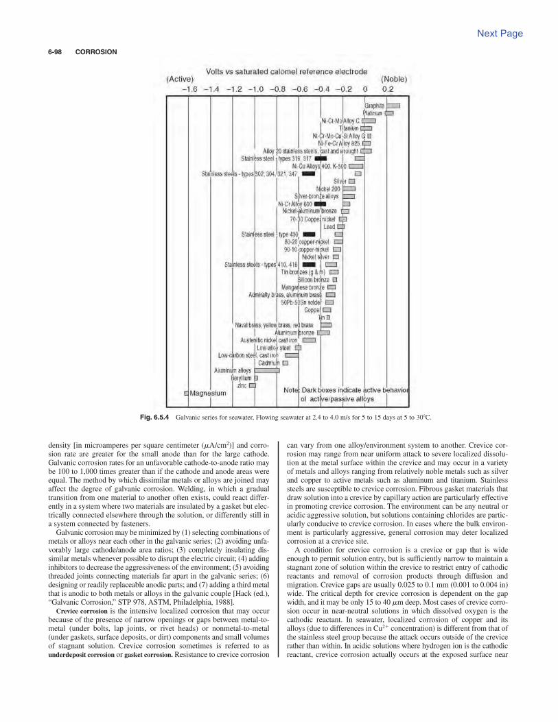
density [in microamperes per square centimeter (mA/cm2)] and corro-sion rate are greater for the small anode than for the large cathode.Galvanic corrosion rates for an unfavorable cathode-to-anode ratio maybe 100 to 1,000 times greater than if the cathode and anode areas wereequal. The method by which dissimilar metals or alloys are joined mayaffect the degree of galvanic corrosion. Welding, in which a gradualtransition from one material to another often exists, could react differ-ently in a system where two materials are insulated by a gasket but elec-trically connected elsewhere through the solution, or differently still ina system connected by fasteners.Galvanic corrosion may be minimized by (1) selecting combinations of
metals or alloys near each other in the galvanic series; (2) avoiding unfa-vorably large cathode/anode area ratios; (3) completely insulating dis-similar metals whenever possible to disrupt the electric circuit; (4) addinginhibitors to decrease the aggressiveness of the environment; (5) avoidingthreaded joints connecting materials far apart in the galvanic series; (6)designing or readily replaceable anodic parts; and (7) adding a third metalthat is anodic to both metals or alloys in the galvanic couple [Hack (ed.),“Galvanic Corrosion,” STP 978, ASTM, Philadelphia, 1988].
Crevice corrosion is the intensive localized corrosion that may occurbecause of the presence of narrow openings or gaps between metal-to-metal (under bolts, lap joints, or rivet heads) or nonmetal-to-metal(under gaskets, surface deposits, or dirt) components and small volumesof stagnant solution. Crevice corrosion sometimes is referred to asunderdeposit corrosion or gasket corrosion. Resistance to crevice corrosion
can vary from one alloy/environment system to another. Crevice cor-rosion may range from near uniform attack to severe localized dissolu-tion at the metal surface within the crevice and may occur in a varietyof metals and alloys ranging from relatively noble metals such as silverand copper to active metals such as aluminum and titanium. Stainlesssteels are susceptible to crevice corrosion. Fibrous gasket materials thatdraw solution into a crevice by capillary action are particularly effectivein promoting crevice corrosion. The environment can be any neutral oracidic aggressive solution, but solutions containing chlorides are partic-ularly conducive to crevice corrosion. In cases where the bulk environ-ment is particularly aggressive, general corrosion may deter localizedcorrosion at a crevice site.A condition for crevice corrosion is a crevice or gap that is wide
enough to permit solution entry, but is sufficiently narrow to maintain astagnant zone of solution within the crevice to restrict entry of cathodicreactants and removal of corrosion products through diffusion andmigration. Crevice gaps are usually 0.025 to 0.1 mm (0.001 to 0.004 in)wide. The critical depth for crevice corrosion is dependent on the gapwidth, and it may be only 15 to 40 mm deep. Most cases of crevice corro-sion occur in near-neutral solutions in which dissolved oxygen is thecathodic reactant. In seawater, localized corrosion of copper and itsalloys (due to differences in Cu2$ concentration) is different from that ofthe stainless steel group because the attack occurs outside of the crevicerather than within. In acidic solutions where hydrogen ion is the cathodicreactant, crevice corrosion actually occurs at the exposed surface near
6-98 CORROSION
Fig. 6.5.4 Galvanic series for seawater, Flowing seawater at 2.4 to 4.0 m/s for 5 to 15 days at 5 to 308C.
Next Page
FORMS OF CORROSION 6-99
the crevice. Decreasing crevice width or increasing crevice depth, bulkchloride concentration, and/or acidity will increase the potential forcrevice corrosion. In some cases, deep crevices may restrict propagationbecause of the voltage drop through the crevice solution (Lee et al.,Corrosion/83, Paper 69, NACE International, Houston, TX, 1983).
A condition common to crevice corrosion is the development of anoccluded localized environment that differs considerably from the bulksolution. The basic overall mechanism of crevice corrosion is the disso-lution of a metal [Eq. (6.5.1)] and the reduction of oxygen to hydroxide ions[Eq. (6.5.4)]. Initially, these reactions take place uniformly, both inside andoutside the crevice. However, after a short time, oxygen within the creviceis depleted because of restricted convection, and oxygen reduction ceasesin this area. Because the area within the crevice is much smaller thanthe external area, oxygen reduction remains virtually unchanged. Onceoxygen reduction ceases within the crevice, the continuation of metal dis-solution tends to produce an excess of positive charge within the crevice.To maintain charge neutrality, chloride or possibly hydroxide ions migrateinto the crevice. This results in an increased concentration of metalchlorides within the crevice, which hydrolyzes in water according toEq. (6.5.8) to form an insoluble hydroxide and a free acid.
(6.5.8)
The increased acidity boosts the dissolution rates of most metals andalloys, which increases migration and results in a rapidly accelerating andautocatalytic process. The chloride concentration within crevices exposedto neutral chloride solutions is typically 3 to 10 times higher than in thebulk solution. The pH within the crevice is 2 to 3. The pH drop with timeand critical crevice solution that will cause breakdown in stainless steelscan be calculated [Oldfield and Sutton, Brit. Corrosion J., 13, no. 13,1978; IJsseling (ed.), “Survey of Literature on Crevice Corrosion(1979–1998),” European Federation of Corrosion Publications, no. 30,IOM Communications, London, 2000].
Optimum crevice corrosion resistance can be achieved with anactive/passive metal that possesses (1) a narrow active/passive transi-tion, (2) a small critical current density, and (3) an extended passiveregion. Crevice corrosion may be minimized by avoiding riveted, lap,or bolted joints in favor of properly welded joints, designing vessels forcomplete drainage and removal of sharp corners and stagnant areas,removing deposits frequently, and using solid, nonabsorbent gaskets(such as Teflon) wherever possible.
Pitting is a form of extremely localized attack that results in a cavityor hole in the metal or alloy. Deterioration by pitting is one of the mostdangerous types of localized corrosion, but its unanticipated occurrencesand propagation rates are difficult to consider in practical engineeringdesigns. Pits are often covered by corrosion products. Depth of pitting issometimes expressed by the pitting factor, which is the ratio of deepestmetal penetration to average metal penetration as determined by weightloss measurements. A pitting factor of 1 denotes uniform corrosion.
Pitting is usually associated with the breakdown of a passive metal.Breakdown involves the existence of a critical potential Eb, induction time ata potential Eb, presence of aggressive species (Cl!, Br!, ClO4
!, etc.), anddiscrete sites of attack. Pitting is associated with local imperfections in thepassive layer. Nonmetallic inclusions, second-phase precipitates, grainboundaries, scratch lines, dislocations, and other surface inhomogeneitiescan become initiation sites for pitting (Szklarska-Smialowska, “Pitting ofMetals,” NACE International, Houston, TX, 1986; Szklarska-Smialowska,“Pitting and Crevice Corrosion,” NACE International, Houston TX, 2005).The induction time before pits initiate may range from days to years.Induction time depends on the metal, aggressiveness of the environment,and the potential, and tends to decrease if either the potential or the con-centration of aggressive species increases.
Once pits are initiated, they continue to grow through an autocatalyticprocess (i.e., the corrosion conditions within the pit are both stimulatingand necessary for continuing pit growth). Pit growth is controlled by therate of depolarization at the cathodic areas. Oxygen in aqueous environ-ments and ferric chloride in various industrial environments are effectivedepolarizers. The propagation of pits is virtually identical to crevicecorrosion. Factors contributing to localized corrosion such as crevice
M1Cl2 1 H2O S MOH T 1 H1Cl2
corrosion and pitting of various materials are found in other publications“Localized Corrosion—Cause of Metal Failure,” STP 516, ASTM,Philadelphia, 1972; Brown et al. (eds.), “Localized Corrosion,” NACE-3,NACE International, Houston, TX, 1974; Isaacs et al., “Advances inLocalized Corrosion,” NACE-9, NACE International, Houston, TX, 1990;Frankel and Newman (eds.), “Critical Factors in Localized Corrosion,” PV92-9, The Electrochemical Society, Pennington, NJ, 1992; Natishan et al.(eds.), “Critical Factors in Localized Corrosion II,” PV 95-15, TheElectrochemical Society, Pennington, NJ, 1996; Natishan et al. (eds.),“Critical Factors in Localized Corrosion III, A symposium in Honor of the70th Birthday of Jerome Kruger,” PV 98-17, The Electrochemical Society,Pennington, NJ, 1999; Virtanen et al. (eds.), “Critical Factors in LocalizedCorrosion IV: A Symposium in Honor of the 65th Birthday of HansBohni,” PV 2002-24, The Electrochemical Society, Pennington, NJ, 2002].
Copper and its alloys suffer localized corrosion by nodular pitting inwhich the attacked areas are covered with small mounds or nodules com-posed of corrosion product and CaCO3 precipitated from the water. The pitinterior is covered with CuCl which prevents formation of a protectiveCu2O layer. Pitting occurs most often in cold, moderately hard to hardwaters, but also happens in soft waters above . Pitting is associatedwith the presence of very thin carbon (cathodic) films from lubricants usedduring tube manufacture. Copper pitting is favored by a high sulfate/chloride ratio. Copper-nickel tubing suffers from accelerated corrosion inseawater due to the presence of both sulfides and oxygen. Sulfides preventthe formation of a protective oxide layer, which allows the anodic reactionto proceed unabated supported by the oxygen reduction reaction.
Caustic corrosion, frequently referred to as caustic gouging or ductile
gouging, is a form of localized corrosion that occurs as a result of fouledheat-transfer surfaces of water-cooled tubes and the presence of an activecorrodent in the water of high-pressure boilers. Porous deposits thatform and grow in these high-heat-input areas produce conditions thatallow sodium hydroxide to permeate the deposits by a process calledwick boiling, and concentrate to extremely high levels (e.g., 100 ppm bulkwater concentrated to 220,000 ppm NaOH in water film under thesedeposits) which dissolves the protective magnetite and then reacts directlywith the steel to cause rapid corrosion. A smooth, irregular thinningoccurs, usually downstream of flow disruptions or in horizontal orinclined tubing (Port and Herro, “The Nalco Guide to Boiler TubeAnalysis,” McGraw-Hill, New York, 1991, pp. 57–70; Shifler and Wilkes,Historical Perspectives of Intergranular Corrosion of Boiler Metal byWater.Corrosion/93, Paper 44, NACE International, Houston, TX, 1993).
Intergranular corrosion is localized attack that follows a narrowpath along the grain boundaries of a metal or an alloy. Intergranular cor-rosion is caused by the presence of impurities, precipitation of one ofthe alloying elements, or depletion of one of these elements at or alongthe grain boundaries. The driving force of intergranular corrosion is thedifference in corrosion potential that exists between a thin grain bound-ary zone and the bulk of immediately adjacent grains. Intergranular cor-rosion most commonly occurs in aluminum or copper alloys andaustenitic stainless steels.
When austenitic stainless steels such as 304 are heated or placed inservice at temperatures of 950 to 14508C, they become sensitized andsusceptible to intergranular corrosion, because chromium carbide(Cr26C6) is formed. This effectively removes chromium from the vicin-ity of the grain boundaries, thereby approaching the corrosion resis-tance of carbon steel in these chromium-depleted areas. Methods toavoid sensitization and control intergranular corrosion of austeniticstainless steels (1) employ high-temperature heat treatment (solutionquenching) at 1950 to 20508C, (2) add elements that are stronger car-bide formers [stabilizers such as columbium (niobium), niobium plustantalum, or titanium] than chromium, and (3) lowering the carbon con-tent below 0.03 percent. Stabilized austenitic stainless steels can expe-rience intergranular corrosion if heated above 22508C, wherecolumbium carbides dissolve, as may occur during welding.Intergranular corrosion of stabilized stainless steels is called knife-lineattack. This attack transpires in a narrow band in the parent metal adja-cent to a weld. Reheating the steel to around 1950 to 22508C reformsthe stabilized carbides.
608C
Previous Page
Surface carburization also can cause intergranular corrosion in castaustenitic stainless steel. Overaging of aluminum alloys can form pre-cipitates such as CuAl2, FeAl3, MgAl3, MgZn2, and MnAl6 along grainboundaries and promote intergranular corrosion. Some nickel alloyscan form intergranular precipitates of carbides and intermetallic phasesduring heat treatment or welding. Alloys with these intergranular pre-cipitates are subject to intergranular corrosion.
Dealloying involves the selective removal of the most electrochemi-cally active constituent metal in the alloy. Selective removal of one metalcan result in either localized attack leading to possible perforation (plugdealloying) or a more uniform attack (layer dealloying) resulting in lossof component strength. Although selective removal of metal such as Al,Fe, Si, Co, Ni, and Cr from their alloys has occurred, the most commondealloying is the selective removal of zinc from brasses, calleddezincification. Dezincification of brasses (containing 15 percent morezinc) takes place in soft waters, especially if the carbon dioxide contentis high. Other factors that increase the susceptibility of brasses to deal-loying are high temperatures, waters with high chloride content, lowwater velocity, crevices, and deposits on the metal surface.Dezincification is experienced over a wide pH range. Layer dezincifica-tion is favored when the environment is acidic and the brass has a highzinc content. Plug dezincification tends to develop when the environmentis slightly acidic, neutral, or alkaline and the zinc content is relatively low.It has been proposed either that zinc is selectively dissolved from thealloy, leaving a porous structure of metallic copper in situ within the brasslattice, or that both copper and zinc are dissolved initially, but copperimmediately redeposits at sites close to where the brass dissolved.
Dezincification can be minimized by reducing oxygen in the envi-ronment or by cathodic protection. Dezincification of -brass (70 per-cent Cu, 30 percent Zn) can be minimized by alloy additions of 1percent tin. Small amounts (~0.05 percent) of arsenic, antimony, orphosphorus promote an effective inhibitor of dezincification for 70/30
-brass (inhibited Admiralty brass). Brasses containing less than 15percent zinc have not been reported to suffer dezincification.
Gray cast iron selectively leaches iron in mild environments, particu-larly in underground piping systems. Graphite is cathodic to iron, whichsets up a galvanic cell. The dealloying of iron from gray cast iron leavesa porous network of rust, voids, and graphite termed graphitization orgraphitic corrosion. The cast iron loses both its strength and its metallicproperties, but experiences no apparent dimensional changes.Graphitization does not occur in nodular or malleable cast irons becausea continuous graphite network is not present. White cast iron also isimmune to graphitization since it has essentially no available free carbon.
Dealloying also can occur at high temperatures. Exposure of stainlesssteels to low-oxygen atmospheres at 18008F (9808C) results in theselective oxidation of chromium and the creation of a more protec-tive scale, and the depletion of chromium under the scale in the sub-strate metal. Decarburization can occur in carbon steel tubing if heatedabove 1,6008F (8708C). Denickelification of austenitic stainless steelsoccurs in liquid sodium.
Corrosion rates are often dependent on fluid flow and availability ofappropriate species required to drive electrochemical reactions. Anincrease in fluid flow may increase corrosion rates by removing protectivefilms or increasing the diffusion or migration of deleterious species. Anincrease in fluid flow may also decrease corrosion rates by eliminatingaggressive ion concentration or enhancing passivation or inhibition bytransporting the protective species to the fluid/metal interface. There are anumber of mechanisms caused by the conjoint action of flow and corro-sion that result in several types of flow-influenced corrosion: (1) masstransport-controlled corrosion, (2) phase transport-controlled corrosion,(3) erosion corrosion, and (4) cavitation (Heitz, Corrosion, 47, no. 135,1991; also Corrosion/90, Paper no. 1, NACE International, Houston, TX,1990). Mass transport-controlled corrosion implies that the rate of corro-sion is dependent on the convective mass transfer processes at themetal/fluid interface. Corrosion by mass transport will often be stream-lined and smooth. Phase transport-controlled corrosion suggests that thewetting of the metal surface by a corrosive phase is flow-dependent. Thismay occur from the separation of one liquid phase from another or by the
a
a
formation of a second phase from a liquid. An example of the secondmechanism is the formation of discrete bubbles or a vapor phase fromboiler water in horizontal or inclined tubes in high-heat-flux areas underlow-flow conditions (departure from nucleate boiling). The distributionand morphology of the corrosive attack will be related to the distributionof the corrosive phase—the corroded sites will frequently display rough,irregular surfaces and be coated with thick, porous corrosion deposits(Shifler, Flow-Influenced Corrosion in a Waste Energy Sparge Line,Mater. Perf. 37, 1998, pp. 38–44).
Erosion corrosion is the acceleration or increase of attack becauseof the relative movement between a corrosive fluid and the metal sur-face. Mechanically, the conjoint action of erosion and corrosion dam-ages not only the protective film but also the metal or alloy surface itselfby the abrasive action of a fluid (gas or liquid) at high velocity. Theinability to maintain a protective passive film on the metal or alloy sur-face raises the corrosion rate. Erosion corrosion is characterized bygrooves, gullies, waves, rounded holes, and valleys, usually exhibitingin a directional manner. Components exposed to moving fluids and sub-ject to erosion corrosion include bends, elbows, tees, valves, pumps,blowers, propellers, impellers, agitators, condenser tubing, orifices, tur-bine blades, nozzles, wear plates, baffles, boiler tubes, and ducts.
The hardness of the alloy or metal and/or the mechanical or protectivenature of the passive film will affect the resistance to erosion corrosion ina particular environment. Copper and brasses are particularly susceptibleto erosion corrosion. Models and experimental results have shown thatflow stream velocity and increases of particle size, sharpness, density, andconcentration increase the erosion corrosion rate. Increases in fluid vis-cosity, density, target material hardness, and/or pipe diameter decreasethe corrosion rate. Often, an escalation in the fluid velocity increases theattack by erosion corrosion. The effect may be nil until a critical velocityis reached, above which attack may increase very rapidly. The criticalvelocity is dependent on the alloy, passive layer, temperature, and natureof the fluid environment. The increased attack may be attributed, in part,to increasing cathodic reactants to the metal surface. Increased velocitymay decrease attack by increasing the effectiveness of inhibitors or bypreventing silt or dirt from depositing and causing crevice corrosion.
Erosion corrosion includes impingement, cavitation, and frettingcorrosion. Impingement attack occurs when a fluid strikes the metalsurface at high velocity at directional change sections such as bends,tees, turbine blades, and inlets of pipes or tubes. In the majority of casesinvolving impingement attack, a geometric feature of the system resultsin turbulence. Air bubbles or solids present in turbulent flow will accen-tuate attack.
Cavitation damage is caused by the formation and collapse of vaporbubbles in a liquid near a metal surface. Cavitation occurs where high-velocity water and hydrodynamic pressure changes are encountered,such as in ship propellers or pump impellers. If pressure on a liquid islowered drastically by flow divergence, the water vaporizes and formsbubbles. These bubbles generally collapse rapidly, producing shockwaves with pressures as high as 60,000 lb/in2 (410 MPa), which destroysthe passive film. The newly exposed metal surface corrodes, reforms apassive film that is destroyed again by another cavitation bubble, and soforth. As many as 2,000,000 bubbles may collapse over a small area in1 s. Cavitation damage causes both corrosion and mechanical effects.
Fretting corrosion is a form of damage caused at the interface oftwo closely fitting surfaces under load when subjected to vibration andslip. Fretting is explained as:(1) the surface oxide is ruptured at local-ized sites prompting reoxidation; or (2) material wear and friction causelocal oxidation. The degree of plastic deformation is greater for softermaterials than for hard; seizing and galling may often occur.Lubrication, increased hardness, increased friction, and the use of gas-kets can reduce fretting corrosion.
Environmentally induced cracking is a brittle fracture of an otherwiseductile material due to the conjoint action of tensile stresses in a spe-cific environment over a period of time. Environmentally inducedcracking includes (1) stress corrosion cracking, (2) hydrogen damage,(3) corrosion fatigue, (4) liquid-metal embrittlement, and (5) solid-metal induced embrittlement.
6-100 CORROSION

FORMS OF CORROSION 6-101
Stress corrosion cracking (SCC) refers to service failures due to thejoint interaction of tensile stress with a specific corrodent and a suscep-tible normally ductile material. The observed crack propagation is theresult of mechanical stress and corrosion reactions. Stress can be exter-nally applied, but most often is the result of residual tensile stresses.SCC can initiate and propagate with little outside evidence of corrosionor macroscopic deformation and usually provides no warning ofimpending failure. Cracks often initiate at surface flaws that were pre-existing or formed during service. Branching is frequently associatedwith SCC; the cracks tend to be very fine and tight and visible only withspecial techniques or by microscopic examination. SCC can be inter-granular or transgranular. Intergranular SCC is often associated withgrain boundary precipitation or grain boundary segregation of alloyconstituents such as found in sensitized austenitic stainless steels.Transgranular SCC is related to crystal structure, anisotropy, grain sizeand shape, dislocation density and geometry, phase composition, yieldstrength, ordering, and stacking fault energies. The specific corrodentsof SCC for different alloys include the following: (1) carbon steels—sodium hydroxide; (2) stainless steels—NaOH or chlorides; (3) -brass—ammoniacal solutions; (4) aluminum alloys—aqueous Cl!, Br!,I!solutions; (5) titanium alloys—aqueous Cl!, Br!, I!solutions, organicliquids; (6) high nickel alloys—high-purity steam [Gangloff and Ives(eds.), “Environment-Induced Cracking of Metals,” NACE-10, NACEInternational, Houston, TX, 1990; Bruemmer et al. (eds.), “ParkinsSymposium on Fundamental Aspects of Stress Corrosion Cracking,”The Minerals, Metals, & Materials Society, Warrendale, PA, 1992;Jones, “Stress Corrosion Cracking: Materials Performance andEvaluation,” ASM International, Materials Park, OH, 1992; Jones (ed.),“Chemistry and Electrochemistry of Corrosion and Stress CorrosionCracking: A Symposium Honoring the Contributions of R. W. Staehle.”The Minerals, Metals, & Materials Society, Warrendale, PA, 2001].
Hydrogen interactions can affect most engineering metals andalloys. Terms to describe these interactions are not universally agreedupon. Hydrogen damage or hydrogen attack is caused by the diffusionof atomic hydrogen through carbon and low-alloy steels. Hydrogenreacts with carbon, either in elemental form or as carbides, to formmethane gas. Methane accumulates at grain boundaries and can causelocal pressures to exceed the yield strength of the material. Hydrogendamage causes intergranular, discontinuous cracks and decarburizationof the steel. Once cracking occurs, the damage is irreversible. In utilityboilers, hydrogen damage has been associated with fouled heat-transfersurfaces. Hydrogen damage is temperature-dependent with a thresholdtemperature of about 4008F (2048C). Hydrogen damage has beenobserved in boilers operating at pressures of 450 to 2700 psi (3.1 to 18.6MPa) and tube metal temperatures of 600 to 9508F (316 to 5108C).Hydrogen damage may occur in either acidic or alkaline conditions,although this contention is not universally accepted.
Hydrogen embrittlement results from penetration and adsorption ofatomic hydrogen into an alloy matrix. This process results in a decreaseof toughness and ductility of alloys due to hydrogen ingress. Hydrogenmay be removed by baking at 200 to 3008F (93 to 1498C), which returnsthe alloy mechanical properties very near to those existing before hydro-gen entry. Hydrogen embrittlement can affect most metals and alloys.Hydrogen blistering results from atomic hydrogen penetration at internaldefects near the surface such as laminations or nonmetallic inclusionswhere molecular hydrogen forms. Pressure from H can cause local plas-tic deformation of surface exfoliation [Moody and Thompson (eds.),“Hydrogen Effects on Materials Behavior,” The Minerals, Metals, &Materials Society, Warrendale, PA, 1990; Shifler and Wilkes, HistoricalPerspectives of Intergranuluar Corrosion of Boiler Metal by Water,Corrosion/93, Paper 44, NACE International, Houston, TX, 1993].
For higher-alloyed steels, the higher the strength of the alloy, themore susceptible the alloy will be to internal hydrogen embrittlementand to hydrogen environmental embrittlement. Hydrogen solubility inan ultrahigh-strength steel (UHHS)/environment system is controlledby trapping and the binding energies of the particular trap sites.Understanding hydrogen interactions and transport in UHSSmicrostructures is necessary to control hydrogen embrittlement (Li et al.,
a
Hydrogen Trap States in Ultrahigh-Strength AERMET 100 Steel,Metallurg. Mater. Trans. A, 35A, no. 849, 2004; Thomas et al., InternalHydrogen Embrittlement of Ultrahigh-Strength AERMET 100 Steel,Metallurg. Mater. Trans. A, 34A, no. 327, 2003).
When a metal or an alloy is subjected to cyclic, changing stresses,cracking and fracture can occur through fatigue at stresses lower thanthe yield stress. A clear relationship exists between stress amplitudeand number of cyclic loads; an endurance limit is the stress level belowwhich fatigue will not occur indefinitely. Fracture solely by fatigue isnot viewed as an example of environmental cracking. However, theconjoint action of a corrosive medium and cyclic stresses on a materi-al is termed corrosion fatigue. Corrosion fatigue failures are usually“thick-walled” brittle ruptures showing little local deformation. Anendurance limit often does not exist in corrosion fatigue failures.Cracking often begins at pits, notches, surface irregularities, weldingdefects, or sites of intergranular corrosion. Surface features of corro-sion fatigue cracking vary with alloys and specific environmental con-ditions. Crack paths can be transgranular (carbon steels, aluminumalloys, etc.) or intergranular (copper, copper alloys, etc.); exceptions tothe norm are found in each alloy system. “Oyster shell” markings maydenote corrosion fatigue failures, but corrosion products and corrosionoften cover and obscure this feature. Cracks usually propagate in thedirection perpendicular to the principal tensile stress; multiple, paral-lel cracks are usually present near the principal crack which led to fail-ure. Applied cyclic stresses are caused by mechanical restraints orthermal fluctuations; susceptible areas may also include structures thatpossess residual stresses from fabrication or heat treatment. Low pH,and high stresses, stress cycles, and oxygen content or corrosivespecies concentrations will increase the probability of corrosionfatigue cracking [McEvily and Staehle (eds.), “Corrosion Fatigue-Mechanics, Metallurgy, Electrochemistry, and Engineering,” STP 801,ASTM, Philadelphia, 1983; [McEvily and Staehle (eds.), “CorrosionFatigue-Chemistry, Mechanics, and Microstructure,” NACE International,Houston, TX, 1986].
Liquid-metal embrittlement (LME) or liquid metal–induced embrittle-ment is the catastrophic brittle fracture of a normally ductile metal whencoated by a thin film of liquid metal and subsequently stressed in ten-sion. Cracking may either be intergranular or transgranular. Usually, asolid that has little or no solubility in the liquid and forms no inter-metallic compounds with the liquid constitutes a couple with the liquid.Fracture can occur well below the yield stress of the metal or alloy(Jones, Eng. Failure Anal. 1, no. 51, 1994). A partial list of examples ofLME includes (1) aluminum (by mercury, gallium, indium, tin-zinc,lead-tin, sodium, lithium, and inclusions of lead, cadmium, or bismuthin aluminum alloys); (2) copper and select copper alloys (mercury, anti-mony, cadmium, lead, sodium, lithium, and bismuth); (3) zinc (mercury,gallium, indium, Pb-Sn solder); (4) titanium or titanium alloys (mercury,zinc, and cadmium); (5) iron and carbon steels (aluminum, antimony,cadmium, copper, gallium, indium, lead, lithium, zinc, and mercury);and (6) austenitic and nickel-chromium steels (tin and zinc).
Solid metal–induced embrittlement (SMIE) occurs below the meltingtemperature Tm of the solid in various LME couples. Many instances ofloss of ductility or strength, and brittle fracture have taken place with elec-troplated metals or coatings and inclusions of low-melting alloys belowTm. Cadmium-plated steel, leaded steels, and titanium embrittled by cad-mium, silver, or gold are materials affected by SMIE. The prerequisites forSMIE and LME are similar, although multiple cracks are formed in SMIEand SMIE crack propagation is 100 to 1,000 times slower than LME crack-ing. More detailed descriptions of LME and SMIE are given elsewhere[Kambar (ed.), “Embrittlement of Metals,” American Institute of Mining,Metallurgical and Petroleum Engineers, St. Louis, MO, 1984].
High-temperature corrosion may occur in many environments and isaffected by numerous factors such as temperature, alloy or protective coat-ing composition, time, and gas composition. The rate by which a materialmay degrade in a high-temperature environment will depend on thereaction or range of operative reactions, the reaction thermodynamics,kinetics, and chemical physical properties of the material exposed to thisenvironment. A material can degrade at high temperatures upon exposure
to gaseous, liquid (molten ash, salts, or metal/alloys), or solid-state reac-tion processes such as diffusion and interdiffusion, precipitation, and creep.
High-temperature corrosion/degradation of materials may occurthrough a number of potential processes: (1) oxidation, (2) carburiza-tion and metal dusting, (3) nitridation, (4) sulfidation, (5) hot corrosion,(6) chloridation and other halogenization reactions, (7) hydrogen inter-actions, (8) molten metals, (7) molten salts, (8) aging reactions such assensitization, (9) creep, and (10) erosion corrosion and wear. Variousmaterials (alloys, high-temperature coatings, refractories, glasses) areexposed to high-temperature environments and experience varyingdegrees of degradation (Pond and Shifler, High Temperature CorrosionFailures, in vol. 11: “Failure-Analysis, Metals Handbook,” ASMInternational, Materials Park, OH, 2002; Shifler, High TemperatureGaseous Corrosion Testing, vol. 13A, “Corrosion Principles, ASMHandbook,” ASM International, Materials Park, OH, 2003).
Oxide growth advances with time by parabolic, linear, cubic, or loga-rithmic rates. The corrosion rate can be influenced considerably by thepresence of contaminants, particularly if they are adsorbed on the metalsurface. Each alloy has an upper temperature limit at which the oxidescale, based on its chemical composition and mechanical properties, can-not protect the underlying alloy. Catastrophic oxidation refers to metal-oxygen reactions that occur at continuously increasing rates or breakaway from protective behavior very rapidly. Molybdenum, tungsten,vanadium, osmium, rhenium, and alloys containing Mo or V may oxidizecatastrophically. Internal oxidation may take place in copper- or silver-based alloys containing small levels of Al, Zn, Cd, or Be when more sta-ble oxides are possible below the surface of the metal/scale interface.Sulfidation forms sulfide phases with less stable-base metals, rather thanoxide phases, when H2S, S2, SO2, and other gaseous sulfur species havea sufficiently high concentration. In corrosion-resistant alloys, sulfidationusually occurs when Al or Cr ties up with sulfides which interferes withthe process of developing an oxide. Carburization of high-temperaturealloys is possible in reducing carbon-containing environments. Hotcorrosion involves the high-temperature, liquid-phase attack of alloys byeutectic alkali-metal sulfates that solubilize a protective alloy oxide, andexposes the bare metal, usually iron, to oxygen which forms more oxideand promotes subsequent metal loss at temperatures of 1,000 to 1,3008F(538 to 7048C). Vanadium pentoxide and sodium oxide can also formlow-melting-point [~1,0008F (5388C)] liquids capable of causing alloycorrosion. These are usually from contaminants in fuels, either coal or oil.
Alloy strength decreases rapidly when metal temperatures approach900 to 1,0008F and above. Creep entails a time-dependent deformationinvolving grain boundary sliding and atom movements at high tempera-tures. When sufficient strain has developed at the grain boundaries, voidsand microcracks develop, and grow and coalesce to form larger cracksuntil failure occurs. Creep rate will increase and the projected time to fail-ure will decrease when stress and/or tube metal temperature is increased[Rapp (ed.), “High Temperature Corrosion,” NACE-10, NACEInternational Houston, TX, 1983; Lai, “High Temperature Corrosion ofEngineering Alloys,” ASM International, Materials Park, OH, 1990;Gleeson, High-Temperature Corrosion of Metallic Alloys and Coatings, inSchütze (ed.), “Corrosion and Environmental Degradation of Materials,”vol. 19 of the series “Materials Science and Technology,” Wiley-VCH,Germany, 2000, pp. 173–228; Khanna, “Introduction to High TemperatureOxidation and Corrosion,” ASM International, Materials Park, OH, 2002;Tortovelli et al. (eds.), “John Stringer Symposium on High TemperatureCorrosion,” ASM International, Materials Park, OH, 2003; Opila et al.,“High Temperature Corrosion and Materials Chemistry IV,” PV 2003-12,The Electrochemical Society, Pennington, NJ, 2003; Edwards et al.,“Proceedings of the Workshop on Materials and Practice to ImproveResistance to Fuel Derived Environmental Damage in Land and SeaBased Turbines.” October 22–23, 2002, EPRI Publication, Electric PowerResearch Institute, Palo Alto, CA, 2003].
CORROSION TESTING
Corrosion testing can reduce cost, improve safety, and conserve resourcesin industrial, commercial, and personal components, processes, and
applications. Corrosion evaluation includes laboratory, pilot-plant, andfield monitoring and testing. The selection of materials for corrosionresistance in specific industrial services is best effected by field testingand actual service performance. However, uncontrollable environmentalfactors may skew precise comparison of potential alloys or metals, andtest times may be unrealistically long. Accelerated corrosion tests in thelaboratory can provide practical information to assess potential materialcandidates in a given environment, predict the service life of a product orcomponent, evaluate new alloys and processes, assess the effects of envi-ronmental variations or conditions on corrosion and corrosion controlmethods, provide quality control, and study corrosion mechanisms.
Careful planning is essential to obtain meaningful, representative,and reliable test results. Metallurgical factors, environmental variables,statistical treatment, and proper interpretation and correlation of accel-erated test results to actual field conditions are considerations in plan-ning and conducting corrosion tests. The chemical composition,fabrication and metallurgical history, identification, and consistency ofmaterials should be known. Although, ideally, the surface condition ofthe test specimen should mirror the plant conditions, a standard testcondition should be selected and maintained. This often requires pre-scribed procedures for cutting, surface finishing, polishing, cleaning,chemical treatment or passivation, measuring and weighing, and han-dling. The exposure technique should provide easy assessment of theenvironment to the sample and should not directly cause conditions fortest corrosion (e.g., crevice corrosion) unrelated to field conditions.
The type, interval, and duration of the tests should be seriously consid-ered. Corrosion rates of the material may decrease with time because ofthe formation of protective films or the removal of a less resistant surfacemetal. Corrosion rates may increase with time if corrosion-inducting saltsor scales are produced or a more resistant metal is removed. The environ-ment may change during testing because of the decrease or increase inconcentration of a corrosive species or inhibitor, or the formation of auto-catalytic products or other metal-catalyzed variations in the solution.These test solution variations should be recognized and related to fieldcondition changes during time, if possible. Testing conditions should pre-scribe the presence or absence of oxygen in the system. Aeration, or thepresence of oxygen, can influence the corrosion rate of an alloy in solu-tion. Aeration may increase or decrease the corrosion rate based on theinfluence of oxygen in the corrosion reaction or the nature of the passivefilms which develop on different metals and alloys. Temperature is anextremely important parameter in corrosion reactions. The temperature atthe specimen surface should be known; a rough rule of thumb is that thecorrosion rate doubles for each 108C rise in temperature (Shifler and Aylor,Considerations for the Testing of Materials and Components in Seawater,Corrosion/2002, Paper 217, Houston, TX, 2002).
Accelerated laboratory corrosion tests are used to predict corrosionbehavior when service history is unavailable and cost and time prohib-it simulated field testing. Laboratory tests also can provide screeningevaluations before field testing. Such tests include nonelectrochemicaland sophisticated electrochemical tests. Nonelectrochemical laboratorytechniques include immersion and various salt spray tests to evaluatethe corrosion of ferrous and nonferrous metals and alloys, as well as thedegree of protection afforded by both organic and inorganic coatings.Since these are accelerated tests by design, the results must be inter-preted cautiously. Standardized test methods are very effective forboth specifications and routine tests used to evaluate experimental orcandidate alloys, inhibitors, coatings, and other materials. Many suchtests are described in the “Annual Book of ASTM Standards” (vol. 3.02,“Metal Corrosion, Erosion, and Wear”) and in standard test methodsfrom the NACE International Book of Standards.
Electrochemical techniques are attractive because they allow a directmethod of accelerating corrosion processes without changing the envi-ronment, can be used as a nondestructive tool to evaluate corrosion rates,and offer in situ (field) or ex situ (laboratory) investigations. Most typicalforms of corrosion can be investigated by electrochemical techniques.Electrochemical tests may include linear polarization resistance, ac elec-trochemical impedance, electrochemical noise, cyclic voltammetry, cyclicpotentiodynamic polarization, potentiodynamic and potentiostatic
6-102 CORROSION

CORROSION PROTECTION METHODS 6-103
polarization, and scratch-repassivation. AC impedance has been used tomonitor coating integrity and evaluate the effectiveness of cathodic pro-tection and coating systems in underground piping. There are complica-tions involved in various electrochemical test methods which must beresolved or eliminated before interpretation is possible. The methodsused above employ a potentiostat, an instrument that regulates the elec-trode potential and measures current as a function of potential. A gal-vanostat varies potential as a function of current.
Corrosion coupons are generally easy to install, reflect actual envi-ronmental conditions, and can be used for long exposure tests. Couponscan evaluate inhibitor programs and are designed to measure specificforms of corrosion. A simple embrittlement detector covered by ASTMD807 permits concentration of boiler water on a stressed steel specimento detect caustic cracking. Field coupon testing has several limitations:(1) It cannot detect brief process upsets; (2) it cannot guarantee initia-tion of localized corrosion rates before the coupons are removed; (3) itcannot directly correlate the calculated coupon corrosion rate to equip-ment or component corrosion; and (4) it cannot detect certain forms ofcorrosion. Corrosion rate sensors created to monitor the corrosion oflarge infrastructural components in real time have been developed foraqueous, soil, and concrete environments using linear polarizationresistance (Ansuini et al., Corrosion/95, Paper 14, NACE International,Houston, TX, 1995). Ultrasonic thickness, radiography, or eddy currentmeasurements can evaluate corrosion rates in situ. The component sur-faces must be clean (free of dirt, paint, corrosion products) to makemeasurements. Ultrasonic attenuation techniques have been applied toevaluate the extent of hydrogen damage. A noncontact nondesctructiveinspection technique for pitting, SCC, and crevice corrosion has beendeveloped using digital speckle correlation (Jin and Chiang,Corrosion/95, Paper 535, NACE International, Houston, TX, 1995).ASTM [Baboian (ed)., “Manual 20—Corrosion Tests and Standards:Application and Interpretation,” ASTM, Philadelphia, 1995; Baboian(ed.), “Manual 20—Corrosion Tests and Standards: Application andInterpretation,” ASTM, International, West Conshohocken, PA, 2005]provides a detailed comprehensive reference for field and laboratory test-ing in different environments of metals and alloys, coatings, and com-posites. It includes testing for different corrosion forms and for differentindustrial applications.
CORROSION PROTECTION METHODS
The basis of corrosion protection methods involves restricting or con-trolling anodic and/or cathodic portions of corrosion reactions, chang-ing the environment variables, or breaking the electrical contactbetween anodes and cathodes. Corrosion protection methods comprise(1) proper materials selection, (2) design, (3) coatings, (4) use ofinhibitors, (5) anodic protection, and (6) cathodic protection [Baboian(ed.), “NACE Corrosion Engineer’s Reference Book,” 3d ed., NACEInternational, Houston, TX, 2002].
The most common way to reduce corrosion is to select the right mate-rial for the environmental conditions and applications. Ferrous and non-ferrous metals and alloys, thermoplastics, nonmetallic linings, resincoatings, composites, glass, concrete, and nonmetal elements are a few ofthe potential materials available for selection (Mangonon, “ThePrinciples of Materials Selection for Engineering Design,” Prentice-Hall,New York, 1999). Experience and data, either in-house or from outsidevendors and fabricators, may assist in the materials selection process.Many materials can be eliminated by service conditions (temperature,pressure, strength, chemical compatibility). Corrosion data for a particu-lar chemical or environment may be obtained through a literature survey(“Corrosion Abstracts,” NACE International; “Corrosion Data Survey—Metals Section,” 6th ed., 1985; “Handbook of Corrosion Data,” 2d ed.,ASM International, Materials Park, OH, 1994; “Corrosion DataSurvey—Nonmetals Section,” 5th ed., NACE International, Houston,TX, 1975) or from expert systems or databases. Different organizations(ASTM, ASM International, ASME, NACE International) may offer ref-erences to help solve problems and make predictions about the corrosionbehavior of candidate materials. The material should be cost-effective
and resistant to the various forms of corrosion (discussed earlier) that maybe encountered in its application. General rules may be applied to deter-mine resistance of metals and alloys. For reducing or nonoxidixing envi-ronments (such as air-free acids and aqueous solutions) nickel, copper, andtheir alloys are usually satisfactory. For oxidizing conditions, chromiumalloys are used, while in extremely powerful oxidizing environments, tita-nium and its alloys have shown superior resistance. The corrosion resis-tance of chromium and titanium can be enhanced in hot, concentrated,oxidizer-free acid by small additions of platinum, palladium, or rhodium.
Many costs related to corrosion could be eliminated by properdesign. The designer should have a credible knowledge of corrosion orshould work in cooperation with a materials and corrosion engineer.The design should avoid gaps or structures where dirt or deposit couldeasily form crevices; horizontal faces should slope for easy drainage.Tanks should be properly supported and employ the use of drip skirtsand dished, fatigue-resistant bottoms (“Guidelines for the WeldedFabrication of Nickel Alloys for Corrosion-Resistant Service,” Pt. 3,Nickel Development Institute, Toronto, Canada, 1994). Connectionsshould avoid dissimilar metals or alloys widely separated in the galvan-ic series for lap joints or fasteners, if possible. Welded joints shouldavoid crevices, microstructural segregation, and high residual or appliedstresses. Positioning of parts should account for prevailing environ-mental conditions. The design should avoid local differences in con-centration, temperature, and velocity or turbulence. All parts requiringmaintenance or replacement must be easily accessible. All parts to becoated must be accessible for the coating application.
Metal and alloys degrade by several known corrosion mechanisms.Relatively thin coatings of metallic, organic, and inorganic materialscan provide an effective barrier between metals/alloys and their envi-ronment. Protective coatings include metallic, chemical conversion,inorganic nonmetallic, and organic coatings. Before the application ofan effective coating on metals and alloys, it is necessary to clean thesurface carefully to remove, dirt, grease, salts, and oxides such as millscale and rust. Metallic coatings may be applied by cladding, elec-trodeposition (copper, cadmium, nickel, tin, chromium, silver, zinc,gold), hot dipping (tin, zinc/galvanizing, lead, and aluminum), diffusion(chromium/chromizing, zinc/sherardizing, boron, silicon, aluminum/calorizing or aluminizing, tin, titanium, molybdenum), metallizing orflame spraying (zinc, aluminum, lead, tin, stainless steels), vacuumevaporation (aluminum), ion implantation, and other methods. All com-mercially prepared coatings are porous to a degree. Corrosion or gal-vanic action may influence the performance of the metal coating. Noble(determined by the galvanic series) coatings must be thicker and have aminimum of pores and small pore size to delay entry of a deleteriousfluid. Some pores of noble metal coatings are filled with an organic lac-quer, or a second, lower-melting metal is diffused into the initial coat-ing. Sacrificial or cathodic coatings such as cadmium, zinc, and in someenvironments, tin and aluminum, cathodically protect the base metal.Porosity of sacrificial coatings is not critical as long as cathodic protec-tion of the base metal continues. Higher solution conductivity allowslarger defects in the sacrificial coating; thicker coatings provide longertimes of effective cathodic protection.
Conversion coatings are produced by electrochemical reaction of themetal surface to form adherent protective corrosion products. Anodizingaluminum forms a protective film of Al2O3. Phosphate and chromatetreatments provide temporary corrosion resistance and usually provide abase for painting. Chromates are extremely effective and widely used ascorrosion inhibitors for high-strength Al alloys in aerospace applica-tions. The combined properties of storage, release, migration, and irre-versible reduction provided by chromate coatings underlie theiroutstanding corrosion protection. Of special note is the action of CrVI asa “suicidal inhibitor” in which reduction to CrIII locks in the inhibitingfilm by converting mobile CrVI to insoluble form and substituting inertCrIII, as discovered in the university research program for the U.S. AirForce (Frankel, Mechanism of Al Alloy Corrosion and the Role ofChromate Inhibitors, AFOSR contact no. F49620-96-1-0479, FinalReport, Dec. 1, 2001). Inorganic nonmetallic coatings include vitreousenamels, glass linings, cement, or porcelain enamels bonded on metals.
Susceptibility to mechanical damage and cracking by thermal shock aremajor disadvantage of these coatings. An inorganic coating must be per-fect and defect-free unless cathodic protection is applied.
Paints, lacquers, coal-tar or asphalt enamels, waxes, and varnishesare typical organic coatings. Converted epoxy, epoxy polyester, moisture-cured polyurethane, vinyl, chlorinated rubber, epoxy ester, oil-modifiedphenolics, and zinc-rich organic coatings are other barriers used tocontrol corrosion. Paints, which are a mixture of insoluble particles ofpigments (e.g., TiO2, Pb3O4, Fe2O3, ZnCrO4) in a continuous organic oraqueous vehicle such as linseed or tung oil, are the most commonorganic coatings. All paints are permeable to water and oxygen to adegree and are subject to mechanical damage and eventual breakdown.Inhibitor and antifouling agents are added to improve corrosion protec-tion. Underground pipelines and tanks should be covered with thickercoatings of asphalt or bituminous paints, in conjunction with cloth orplastic wrapping. Polyester and polyethylene have been used for tanklinings and as coatings for tank bottoms [Munger, “CorrosionPrevention by Protective Coatings,” NACE International, Houston, TX,1984; Munger and Vincent, “Corrosion Prevention by ProtectiveCoatings,” 2d ed., NACE International, Houston, TX, 1999; Fedrizziand Bonora (eds.), Organic and Inorganic Coatings for CorrosionPrevention—Research and Experiences, European Federation ofCorrosion Report No. 20, Institute of Materials, London, 1997].
Inhibitors, when added above a threshold concentration, decrease thecorrosion rate of a material in an environment. If the level of an inhibitoris below the threshold concentration, corrosion could be acceleratedmore than if the inhibitor were completely absent. Inhibitors may beorganic or inorganic and fall into several different classes: (1) passivatorsor oxidizers; (2) precipitators; (3) cathodic or anodic; (4) organic adsor-bents; (5) vapor phase; and (6) slushing compounds. Any one inhibitormay be grouped into one or more classifications. Factors such as tem-perature, fluid velocity, pH, salinity, cost, solubility, interfering species,and metal or alloy may determine both the effectiveness and the choiceof inhibitor. Federal EPA regulations may limit inhibitor choices (suchas chromate use) based on its toxicity and its disposal requirements.
Passivators in contact with the metal surface act as depolarizers, ini-tiating high anodic current densities and shifting the potential into thepassivation range of active/passive metal and alloys. However, if pres-ent in concentrations below 10!3 to 10!4 M, these inhibitors can causepitting. Passivating inhibitors are anodic inhibitors and may includeoxidizing anions such as chromate, nitrite, and nitrate. Phosphate,molybdate, and tungstate require oxygen to passivate steel and are con-sidered nonoxidizing. Nonoxidizing sodium benzoate, cinnamate, andpolyphosphate compounds effectively passivate iron in the near-neutralrange by facilitating oxygen adsorption. Alkaline compounds (NaOH,Na3PO4, Na2B4O7, and Na2O-nSiO4) indirectly assist iron passivationby enhancing oxygen adsorption.
Precipitators are film-forming compounds which create a generalaction over the metal surface and subsequently indirectly interfere withboth anodes and cathodes. Silicates and phosphates in conjunction withoxygen provide effective inhibition by forming deposits. Calcium andmagnesium interfere with inhibition by silicates; 2 to 3 ppm ofpolyphosphates are added to overcome this. The levels of calcium andphosphate must be balanced for effective calcium phosphate inhibition.Addition of a zinc salt often improves polyphosphate inhibition.
Cathodic inhibitors (cathodic poisons, cathodic precipitates, oxy-gen scavengers) are generally cations which migrate toward cathodesurfaces where they are selectively precipitated either chemically orelectrochemically to increase circuit resistance and restrict diffusion ofreducible species to the cathodes. Cathodic poisons interfere with andslow the HER reaction, thereby slowing the corrosion process.Depending on pH, arsenic, bismuth, antimony, sulfides, and selenidesare useful cathodic poisons. Sulfides and arsenic can cause hydrogenblistering and hydrogen embrittlement. Cathodic precipitation-typeinhibitors such as calcium and magnesium carbonates and zinc sulfatein natural waters require adjustment of the pH to be effective. Oxygenscavengers help inhibit corrosion, either alone or with anotherinhibitor, to prevent cathodic depolarization. Sodium sulfite, hydrazine,
carbohydrazide, hydroquinone, methylethylketoxime, and diethylhy-droxylamine are oxygen scavengers.
Organic inhibitors, in general, affect the entire surface of a corrodingmetal and affect both the cathode and anode to differing degrees,depending on the potential and the structure or size of the molecule.Cationic, positively charged inhibitors such as amines and anionic, neg-atively charged inhibitors such as sulfonates will be adsorbed preferen-tially depending on whether the metal surface is either negatively orpositively charged. Soluble organic inhibitors form a protective layeronly a few molecules thick; if an insoluble organic inhibitor is added,the film may become about 0.003 in (76 mm) thick. Thick films showgood persistence by continuing to inhibit even when the inhibitor is nolonger being injected into the system.
Vapor-phase inhibitors consist of volatile aliphatic and cyclic aminesand nitrites that possess high vapor pressures. Such inhibitors are placedin the vicinity of the metal to be protected (e.g., inhibitor-impregnatedpaper) which transfers the inhibiting species to the metal by sublimationor condensation where they adsorb on the surface and retard the cathodic,anodic, or both corrosion processes. This inhibitor protects against waterand/or oxygen. Vapor-phase inhibitors are usually effective only if used inclosed spaces and are used primarily to retard atmospheric corrosion.Slushing compounds are polar inorganic or organic additives in oil, grease,or wax that adsorb on the metal surface to form a continuous protectivefilm. Suitable additives include organic amines, alkali and alkaline-earthmetal salts of sulfonated oils, sodium nitrite, and organic chromates[Nathan (ed.), “Corrosion Inhibitors,” NACE International, Houston, TX,1973; Raman and Labine (eds.), “Reviews of Corrosion Inhibitor Scienceand Technology,” vol. 1, NACE International, Houston, TX, 1993; Ramanand Labine (eds.), “Reviews of Corrosion Inhibitor Science andTechnology,” vol. 2, NACE International Houston, TX, 1996].
Environmental concerns and regulations over using some traditionalcorrosion control materials have led to research and implementation ofalternative corrosion control technologies for (1) volatile organic com-pounds (VOCs), (2) chromates, and (3) cadmium. By far the most impor-tant environmental impact from paints and coatings is the release of VOCsfrom drying. Virtually everything but the solids in a typical coating for-mulation is released to the air around the surface being coated. In anenclosed system, such as a paint booth, some of this emission may be cap-tured before release to the atmosphere. New coating formulations withhigher proportions of solids meet current environmental requirements,eventually, 100 percent solids coating formulations will be common.
Hexavalent chromium is a cancer hazard that can damage lungs,skin, eyes, and nasal passages. Substitutes for hard chromium coatingsare trivalent chromium, nickel-based binary and ternary plating chem-icals. Alternatives to electroplating are pressure-controlled atomizationprocesses (Thermal Spray) high-velocity oxygen fuels (HVOF)processes, amorphous nanocrystalline composite depositions, flexiblepreceramic coatings deposition, organic sealants application, inductive-coupled radio-frequency plasma torch, and cold spray. Cadmium plat-ing has been used to protect steel components in marine environments.Cadmium has been used because of its hardness, close dimensional tol-erance, lubricity, and ability to restrict hydrogen permeation into or outof high-strength steels. Cadmium plating is frequently used for fasten-ers and other very tight tolerance parts because of the dual qualities oflubricity at minimal thickness and superior sacrificial corrosion pro-tection. However, cadmium is highly toxic to personnel and the envi-ronment, thereby necessitating the search for alternative corrosioncontrol coating systems. Research is vigorous to develop cadmiumreplacement coatings with mechanical and sacrificial properties andcorrosion performance equivalent to or exceeding those of cadmium.Coatings that show some promise are Zn-Ni, Zn-Sn, and Ni-Zn-P;Al-Co-Ce alloys; but further research and testing will be required.
The degradation of materials in marine environments depends on theexpected materials demands and service requirements for the compo-nent or systems. Corrosion is dependent on a number of factors, andunderstanding these factors can optimize the ability of modeling to pre-dict galvanic interactions in various environments and under variousoperating conditions.
6-104 CORROSION

CORROSION IN INDUSTRIAL AND POWER PLANT STEAM-GENERATING SYSTEMS 6-105
The computational, storage, and analytical instrumentations are readilyavailable to organize, compile, and verify the many corrosion models
developed from previous materials-based research and empirical investi-gations related to materials performance in the various environments.This is an arduous task for there are many parameters and factors, whichaffect passivity and the breakdown of passivity of materials. These arelimited corrosion models that can describe, formulate, and improve ourunderstanding of materials interactions leading to protection or corrosionin marine environments. Yet, small changes, additions, or subtractions ofvarious environmental parameters may alter (1) the corrosion resistanceof materials, (2) the precise mechanism(s) of breakdown, and (3) theaccuracy of corrosion models to explain the mode of breakdown. It isimportant that computational or mechanistic models not be used beyondtheir capabilities. In the future, fundamental research on the atomic levelwill help clarify many aspects of current corrosion models, modify earlierempirically based models, or develop and verify new corrosion models.Fundamentally based research will also improve our understanding ofcritical materials properties and the effects that various marine environ-mental interactions have on materials. Better physical and computationalmodels will improve our understanding of corrosion and corrosion con-trol that can lead to predictive and prognostic capabilities to better struc-tural design [Shifler, Galvanic Corrosion Modeling in Flowing Systems,“Proc. ELECTROCOR 2005: Simulation of Electrochemical Processes,”Brebbia et al. (eds.), WITPress, Southampton, UK, 2005, p. 59; Shifler,Understanding Materials Interactions in Marine Environments toPromote Extended Structural Life, Corrosion Sci. 2005].
Anodic protection is based on formation of a protective film on metalsby externally applied anodic currents. Figure 6.5.5 illustrates the effect.The applied anodic current density is equal to the difference between thetotal oxidation and reduction rates of the system, or iapp" ioxid! ired. Thepotential range in which anodic protection is achieved is the protectionrange or passive region. At the optimum potential EA, the applied cur-rent is approximately 1 mA/cm2. Anodic protection is limited to active/passive metals and alloys and can be utilized in environments rangingfrom weak to very aggressive. The applied current is usually equal to thecorrosion of the protected system, which can be used to monitor theinstantaneous corrosion rate. Operating conditions in the field usually canbe accurately and quickly determined by electrochemical laboratory tests(Riggs and Locke, “Anodic Protection—Theory and Practice in thePrevention of Corrosion,” Plenum Press, New York, 1981).
Cathodic protection (CP) controls corrosion by supplying electronsto a metal structure, thereby suppressing metal dissolution and increas-ing hydrogen evolution. Figure 6.5.5 shows that when an applied cathodiccurrent density (iapp" ired! ioxid) of 10,000 mA/cm2 on a bare metal sur-face shifts the potential in the negative or active direction to Ec, the cor-rosion rate has been reduced to one mA/cm2. CP is applicable to all met-als and alloys and is common for use in aqueous and soil environments.
CP can be accomplished by (1) impressed current from an externalpower source through an inert anode or (2) use of galvanic couplings bysacrificial anodes. Sacrificial anodes include zinc, aluminum, magne-sium, and alloys containing these metals. The total protective current isdirectly proportional to the surface area of the metal being protected;hence, CP is combined with surface coatings where only the coatingpores or holidays and damaged spots need be cathodically protected[e.g., for 10 mi of a bare pipe, a current of 500 A would be required,while for 10 mi of a superior coated pipe (5 # 106$/ft2) 0.03 A wouldbe required]. The polarization potential can be measured versus a refer-ence, commonly saturated Cu/CuSO4. The criterion for proper CP is!0.85 V versus this reference electrode. Overprotection by CP (denotedby potentials %!0.85 V) can lead to blistering and debonding of thepipe coatings and hydrogen embrittlement of steel from hydrogen gasevolution. Another problem with CP involves stray currents to unintendedstructures. The proper CP for a system is determined empirically andmust resolve a number of factors to be effective [Bianchetti (ed.),“Peabody’s Control of Pipeline Corrosion,” 2d ed., NACE International,Houston, TX, 2001; Morgan, “Cathodic Protection,” 2d ed., NACEInternational, Houston, TX, 1987; von Baeckmann et al. (eds.),“Handbook of Cathodic Corrosion Protection: Theory and Practice ofElectrochemical Protection Processes,” 3d ed., Gulf Publishing, 1997].
CORROSION IN INDUSTRIAL AND POWER PLANTSTEAM-GENERATING SYSTEMS
Types of Steam Generators
The type of steam generator will dictate the types of corrosion-relateddamage experienced. Most steam generators can be grouped into thefollowing categories: heat recovery steam generators (HRSG), direct-fired boilers (i.e., a fuel is burned in the furnace), nuclear steam gener-ators, and electric boilers. This section focuses on the corrosion of twocategories of steam generators: direct-fired boilers and HRSG units.Generally the term steam generator is used here when referring to both.Details about the design of steam generators are discussed in Sec. 9 andthe references [Stultz and Kitto (eds.), “Steam: Its Generation and Use,”40th ed., Babcock and Wilcox, 1992].
Steam/Water Cycle Components
Figure 6.5.6 presents an example of a steam/water cycle for a powerplant with a direct-fired boiler. The flow is basically in a clockwisedirection in the figure. Major components in the cycle include the con-denser, deaerator, boiler (including the economizer, steam generator,superheater, and reheater tubes), and turbine.
Heat recovery steam generator units have simpler condensate/feedwater systems (often with no external feedwater heaters or deaera-tors) and more complicated drum and steam systems (often two or threedrums operating at different pressures with superheated steam from theintermediate-pressure drum feeding the high-pressure cold reheat linesand superheated steam from the low-pressure (LP) drum feeding the LPturbine). For industrial and cogeneration facilities, a portion of thesteam produced would be used in the process, and process condensatenormally would be treated in a condensate polisher and returned to thecondensate/feedwater system.
Steam/Water Cycle Corrosion
Table 6.5.1 provides a summary of the corrosion mechanisms experi-enced in steam/water cycle components. Corrosion can occur on theinternal or external surfaces of the components. In most components,internal pitting refers to the inner diameter (ID) of the tube, andexternal pitting refers to the outer diameter (OD) of heat-transfer tubes.Underdeposit corrosion includes caustic gouging and acid phosphatecorrosion as well as concentration of other salts under deposits (e.g., insteam generator tubes during condenser leaks or other contaminationevents). A detailed (370 pages) discussion of corrosion of steam/watercycle materials was presented in “ASME Handbook on WaterTechnology for Thermal Power Systems,” Chap. 9, ASME, New York,1989. Chapter 17, Management of Cycle Chemistry, of this ASME
Fig. 6.5.5 Effect of applied anodic and cathodic currents on behavior of anactive passive alloy necessary for anodic and cathodic protection, respectively.
10−2 10−1 10 102 103 104 1051
Ecathodic
Ecorr
Eanodic
iapp(Anodic)
Current density10−3
iapp(cathodic)
EE
−
+E°H
2/H
+
M M
+ +e−
H +
+e − H
2
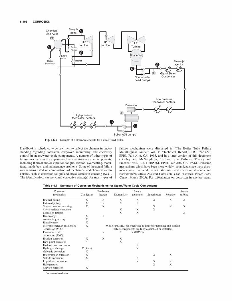
Handbook is scheduled to be rewritten to reflect the changes in under-standing regarding corrosion, carryover, monitoring, and chemistrycontrol in steam/water cycle components. A number of other types offailure mechanisms are experienced by steam/water cycle components,including thermal and/or vibration fatigue, erosion, overheating, manu-facturing defects, and maintenance problems. Some of the actual failuremechanisms listed are combinations of mechanical and chemical mech-anisms, such as corrosion fatigue and stress corrosion cracking (SCC).The identification, cause(s), and corrective action(s) for most types of
failure mechanism were discussed in “The Boiler Tube FailureMetallurgical Guide,” vol. 1: “Technical Report,” TR-102433-VI,EPRI, Palo Alto, CA, 1993, and in a later version of this document(Dooley and McNaughton, “Boiler Tube Failures: Theory andPractice,” vols. 1–3, TR105261, EPRI, Palo Alto, CA, 1996). Corrosionmechanisms which have been more widely recognized since these docu-ments were prepared include stress-assisted corrosion (Labuda andBartholomew, Stress Assisted Corrosion: Case Histories, Power PlantChem., March 2005). For information on corrosion in nuclear steam
6-106 CORROSION
Fig. 6.5.6 Example of a steam/water cycle for a direct-fired boiler.
CF
HP
turbine
IP
turbineLP
Turbine
Condenser
CondensateFeed Pumps
Gland SteamCondenser
Low pressurefeedwater heaters
12
4
High pressurefeedwater heaters
Deaerator
Super-heater
Reheater
Econo-mizer
BolierBlowdown
56
Steam jetejector
Boiler feed pumps
CF
CF
Sample
pointChemical
feed point
S
S
S
S
S
S
S
Table 6.5.1 Summary of Corrosion Mechanisms for Steam/Water Cycle Components
Corrosion Feedwater Steam Steammechanism Condenser heaters Economizer generator Superheater Reheater turbine
Internal pitting X X X X X X XExternal pitting X X X XStress corrosion cracking X X X X XStress-assisted corrosion X X XCorrosion fatigue X X XDealloying X XAmmonia grooving XEnnoblement XMicrobiologically influenced X While rare, MIC can occur due to improper handling and storagecorrosion (MIC) before components are fully assembled or installed.Flow-accelerated X X X (HRSG)corrosion (FAC)Erosion corrosion X X XDew point corrosion * XUnderdeposit corrosion XHydrogen damage X (Rare) XGalvanic corrosion XIntergranular corrosion X X XSulfide corrosion X XLiquid ash corrosion X X XHalogenation X XCrevice corrosion X
*Air-cooled condenser.
CORROSION IN INDUSTRIAL AND POWER PLANT STEAM-GENERATING SYSTEMS 6-107
generators, a detailed government document on corrosion mechanismsand corrosion predictions is available via the Internet (“IncorporatingAging Effects into Probabilistic Risk Assessment—A Feasibility StudyUtilizing Reliability Physics Models,” NUREG/CR-5632, Office ofNuclear Regulatory Research, Washington, DC, August 2001).Deaerators can experience oxygen pitting and corrosion fatigue.
NACE Standard RP0590-96, “Recommended Practice for Prevention,Detection, and Correction of Deaerator Cracking” (1996), was largelywritten in response to deaerator failures from corrosion fatigue cracking.The interconnecting piping in the feedwater system can experience flow-accelerated corrosion (FAC)—sometimes with catastrophic consequences.Corrosion also can be experienced in other steam generator facility com-ponents (e.g., flue gas desulfurization system, gas turbines, wet ash han-dling systems, and makeup and wastewater treatment systems).
Control of Waterside/Steamside Corrosion in the Steam/Water Cycle
To minimize corrosion associated with the water and steam sides ofsteam generators and other steam/water cycle components, a compre-hensive chemistry program should be instituted. A wide variety of chem-ical treatment programs are utilized for these systems depending on thematerials of construction, operating temperatures, pressures, heat fluxes,contaminant levels, and purity criteria for components using the steam.Very general chemistry guidelines for feedwater, boiler water, and
steam for industrial boilers were presented in “Consensus on OperatingPractices for the Control of Feedwater and Boiler Water Chemistry inModern Industrial Boilers,” ASME, New York, 1994. This does notindicate the details of a complete chemistry program. Updated consen-sus documents for chemistry monitoring guidance (“Consensus onOperating Practices for the Sampling and Monitoring of Feedwater andBoiler Water Chemistry in Modern Industrial Boilers,” ASME, NewYork) and for controlling water chemistry (“Consensus on OperatingPractices for Control of Water and Steam Chemistry in CombinedCycle and Cogeneration Power Plants”) are prepared by ASME to pro-vide guidance for heat recovery steam generators.For the electric power industry, a series of detailed chemistry guide-
lines are available from the Electric Power Research Institute (EPRI).EPRI is a research organization funded by its utility members. Its firstchemistry guides were published in 1982 and 1986 for pressurized waterreactor (PWR) nuclear steam generators and fossil-fuel-fired steam gen-erators (respectively) in the electric utility industry. A number of facilitiesexperienced failures in boilers and other cycle chemistry componentsdespite adherence to these guidelines. EPRI continues to update both doc-uments to reflect the changes in understanding regarding corrosion andcorrosion product transport. For example, as of this document, the latestchemistry guideline document for the secondary water system of PWRnuclear steam generators was in its sixth version (2004). EPRI currentlyhas a number of chemistry guidelines tailored for different types of steamgenerators (fossil-fuel-fired boilers, HRSG, fluidized-bed boilers, etc.)For EPRI member organizations, it is suggested that you obtain the latestguideline for your type of steam generator.A good chemistry control program requires a high-purity makeup
water for the steam/water cycle. For high-pressure electric utility boil-ers, two-stage demineralization (e.g., cation/anion/mixed bed ionexchange; reverse osmosis/membrane decarbonation/continuous elec-trodeionization, and combinations of these) is generally utilized.Consult the cited reference for information on design of makeup treat-ment systems (Sheppard T. Powell Associated, LLC, “RevisedGuidelines for Makeup Water Treatment,” TR113692, EPRI, Palo Alto,CA, 1999). For industrial boilers, one- or two-stage demineralization orsoftening (sometimes with dealkalization) is utilized for makeup watertreatment—depending on the boiler pressure. Unsoftened makeup waterhas been utilized in small, low-pressure (e.g., 15 psig, 100 kPa) boil-er systems which receive large amounts of condensate return, but thispractice increases the potential for corrosion and deposition. Somemakeup systems also include vacuum degasifiers for the removal of dis-solved oxygen from the makeup water prior to its entrance into thesteam/water cycle.
Condensate returns often require purification or polishing.Condensate polishing can be achieved with specially designed filters,softeners, or mixed-bed ion exchangers. Industrial boilers typically usesofteners and/or filters (e.g., electromagnetic or cartridge filtration).Once-through boilers typically use full-flow, mixed-bed polishers (pre-ferred) or precoat (with crushed ion exchange resin) filters. Mixed-bedcondensate polishers also are strongly advised for drum-type steamgenerators with condenser cooling water having a high content of chlo-ride and/or a high ratio of hardness to alkalinity. These systems aremore subject to underdeposit corrosion of steam generator tubes in theevent of a condenser tube leak.Minimizing the transport of corrosion products to the steam genera-
tor is essential for corrosion control in the steam generator. Corrosionproducts from the feedwater deposit on steam generator tubes, inhibitcooling of tube surfaces, and provide an evaporative-type concentrationmechanism of dissolved salts under boiler tube deposits. Therefore, thechemistry of water in contact with the tube surfaces is often muchworse than that in the bulk water.There are two basic philosophies of feedwater treatment. The first
type of feedwater treatment, which is used for industrial boilers andmany high-pressure power boilers, relies primarily on raising the feed-water pH to 8.5 to 10 (each plant will have a smaller control range) andmaintaining a reducing environment by eliminating dissolved oxygen(to !5 to 10 ppb) and applying a reducing agent. In this environment,the predominant oxide formed on steel is a mixed metal oxide composedprimarily of magnetite (Fe3O4). The mixed oxide layer on steel formedin deoxygenated solutions resists dissolution or erosion and thus controlsiron transport to the boiler and corrosion of the underlying metal. Copperoxides are maintained in a reduced state (Cu2O) which is less subject totransport to the steam generator (or carryover into the steam). However,excessive application of reducing agents can result in low dissolved oxy-gen levels (!2 ppb) and low oxidizing reduction potentials (ORPs)which render steel susceptible to flow-accelerated corrosion.FAC is the gradual dissolution of magnetite layers from steel surfaces
in flowing systems. It only occurs in areas of high flow or turbulence,and the metal surface often has the scalloped surface morphology,which is sometimes referred to as erosion corrosion. FAC occursbetween 1008C (2128F) and 2508C (4828F) with a maximum attackaround 1508C (3028F) for single-phase FAC and 140 to 1808C (284 to3568F) for two-phase (i.e., steam/water mixtures) FAC. FAC isdecreased by raising the pH, raising the dissolved oxygen level (as lit-tle as 1 to 2 ppb sometimes can have a significant effect), reducing oreliminating the feed of oxygen scavengers (reducing agents), changingto an alloy with greater chromium content (e.g., T22 or P22 providesubstantial resistance), and reducing the flow-induced erosive forces(e.g., decreasing fluid velocity and avoiding pressure reductions orother sources of flashing and two-phase flow).FAC has caused gradual thinning and catastrophic failures of feedwa-
ter lines (several resulting in fatalities), economizer tubes, evaporatortubes (particularly in low-pressure HRSG evaporator sections), heaterdrain lines, and attemperation water lines in power plants. Facilitiesfeeding oxygen scavengers should evaluate their system for areas likelyto have FAC and should check the thickness of metal in those locations.Modeling programs are available for selecting areas for routine evalua-tion of FAC, as discussed in “Flow-Accelerated Corrosion in PowerPlants,” TR-106611, EPRI, Palo Alto, CA, 1996.An adapted version of the deoxygenated (!5 to 10 ppb) feedwater
treatment program for systems without any copper present relies solelyon mechanical deaeration (no reducing agent is applied). This resultsin a slightly more oxidixing solution (typically 1 to 7 ppb of oxygen)and a partially oxidized oxide layer on steel (in the feedwater system)which has been found to be more resistant to FAC than steel with a purelymagnetite layer.The second basic type of feedwater treatment program is oxygenated
treatment (OT). While used for many years in Germany and Russia, OTwas not generally utilized in the United States until the 1990s. Itinvolves a completely different approach from the other treatmentprograms since oxygen is fed and it relies on the formation of a
gamma ferric oxide (Fe2O3) or gamma ferric oxide hydrate (FeOOH)layer on the steel surfaces in the preboiler cycle.Originally, oxygenated treatment was based on neutral pH values
(7 to 8) and oxygen levels of 50 to 250 ppb in very pure feedwater (cationconductivities !0.15 mS/cm). Later, a program based on slightly alkalinepH values (8.0 to 8.5) and 30 to 150 ppb of dissolved oxygen was devel-oped. This treatment program was originally referred to as combinedwater treatment, but it is now commonly referred to as oxygenated treat-ment in the United States. Its application was primarily limited to once-through boilers with all-steel steam/water cycles (if full-flow condensatepolishing is provided, as recommended, copper alloys are permitted in thecondensers). The primary benefit of OT has been to minimize deposit-induced pressure drop through the boiler during service. The reduction iniron oxide transport into and deposition in the boiler can also significantlyreduce the frequency of chemical cleanings. However, OT requiresextremely pure feedwater, and pitting can result from contaminated feed-water. The details of oxygenated treatment programs for once-throughboilers were presented in “Cycle Chemistry Guidelines for Fossil Plants:Oxygenated Treatment,” TR-102285, EPRI, Palo Alto, CA, 1994. Thisdocument also presented guidance for utilizing OT for drum-type boilersand HRSG units, although OT in drum-type units incurs much greater riskbecause feedwater contaminants are concentrated in the drums.As indicated in Fig. 6.5.6, a deaerator is included in many steam/
water cycles for the removal of dissolved oxygen and other noncon-densable gases. Deaerators are direct contact steam heaters which sprayfeedwater into fine droplets and strip the dissolved oxygen from the waterwith steam. This is often referred to as mechanical deaeration. Deaeratorsnormally operate at pressures of 5 to 180 psig (35 to 1,241 kPa), althoughsome old deaerators operated at 1 to 2 psig (6.9 to 13.8 kPa). Most mod-ern deaerators reliably remove dissolved oxygen to 5 to 7 ppb, pro-vided they are properly maintained and operated. While they aresometimes rated for 7 ppb, the performance of deaerating condenserscurrently is more variable in industry and involves maintaining propervacuum, controlling air in-leakage, minimizing condensate subcooling,and deaerating or installing spray headers for the makeup.Following mechanical deaeration, chemical reducing agents called
oxygen scavengers often are applied to minimize residual dissolvedoxygen and/or to inhibit pitting (enhance passivation). This is recom-mended for all systems containing copper in feedwater heaters orsteam-fed heat exchangers (copper corrosion is minimized at 2 ppb)and for steel systems with elevated levels of contamination.A wide variety of oxygen scavengers are utilized. For boilers below
700 to 900 psig (4.8 to 6.2 MPa), sodium sulfite (often catalyzed withcobalt) is commonly used although other nonvolatile or volatile oxy-gen scavengers also may be effective. In industrial boiler systems,severe oxygen tuberculation and pitting and failures of economizertubes have occurred due to excessive oxygen and inadequate feed ofsodium sulfite. A slight excess of sodium sulfite is applied to the feed-water, resulting in a residual of sulfite in the boiler water. The exactlevel of sulfite maintained depends primarily on the boiler pressure andoxygen concentrations in the feedwater, although other factors such asboiler water pH, steam/condensate purity, and feedwater temperaturesare involved. Sodium sulfite should not be used in boilers operatingabove 900 psig (6.2 MPa), as a significant amount of the sulfite decom-poses to volatile sulfur species at the elevated temperatures. The resul-tant acidic species decrease steam and condensate pH values,contributing to increased corrosion in steam/water cycle components.Sulfur species in steam may contribute to SCC. Also, sulfite cannot beused in systems that directly inject feedwater into steam for attemper-ation (desuperheating).Commonly used volatile oxygen scavengers (reducing agents)
include hydrazine, carbohydrazide, hydroquinone, diethylhydroxy-lamine (DEHA), and methylethylketoxime. These are normally appliedto maintain a free residual of the scavenger in the feedwater at the econ-omizer inlet to the boiler. Due to the slower reaction rates, routine dis-solved oxygen monitoring usually is more crucial for boilers usingvolatile oxygen scavengers than for boilers using sulfite. It is possiblefor dissolved oxygen and these volatile reducing agents to coexist due
to slow reaction rates. A benefit and a disadvantage of some of thevolatile oxygen scavengers (e.g., hydrazine, carbohydrazide, DEHA) aretheir ability to enhance metal passivation. This has been useful in sys-tems with poorly operating deaerators because they maintain a mag-netite layer on the steel and appear to inhibit oxygen pitting, despite thepresence of elevated dissolved oxygen levels. However, excessive feedof these volatile reducing agents in systems with demineralized makeupmust be avoided as they can lead to FAC.Sulfite is an effective oxygen scavenger, but has little effect on passi-
vation beyond the effect of oxygen removal. Therefore, it will not convertoxide films on steel and does not cause FAC. However, coexistence ofsulfite and oxygen does not protect the steel against operational oxygenpitting. Additional information on oxygen scavengers can be found in theNACE technical committee report 3A194 (“Oxygen Scavengers in SteamGenerating Systems and in Oil Production,” NACE, Houston, TX, 1994).Aqueous solutions of ammonia or volatile neutralizing amines are
usually applied to the feedwater to control feedwater, steam, and con-densate pH. For all steel cycles these pH levels can range from 9.0 to10.0 with the higher pH values resulting in lower iron oxide transport.The higher pH and amines levels result in higher baseline conductivi-ties, which obscures the ability to detect system contamination (whichincreases the potential for contamination-causing deposits or scale inthe steam generator). In systems containing both steel and copperalloys, pH levels in the feedwater, steam, and condensate are typicallycontrolled in the 8.5 to 9.4 range. The exact pH control limits usuallyare a much tighter range depending on the water purity, amine used,temperature, and type of copper alloys present.Neutralizing amines commonly utilized in steam/water cycles include
cyclohexylamine, morpholine, ethanolamine, diethanolamine, diethy-laminoethanol, dimethyl isopropanolamine, and methoxypropylamine.For large steam distribution systems, a blend of two to four amines withdifferent distribution coefficients (ratio of amine in steam to condensate)is often applied to provide pH control throughout the steam/condensatesystem. Amines tend to decompose in high-pressure, high-temperaturesystems and produce organic acids which may contribute to corrosion.Filming amines are high-molecular-weight amines applied to devel-
op thin films on surfaces to serve as a barrier against corrosion.Applications date at least back to the middle of the twentieth century.Various types of filming amines used up through the 1990s in theUnited States resulted in fouling of equipment (e.g., steam traps, con-densate polishers) when the waxy films and associated iron oxidessloughed off surfaces. New high-molecular-weight amines (currentlycalled polyamines) continue to be introduced and applied. Caution isadvised in the application of this technology.In addition to the condensate/feedwater treatment program, chemistry
must be controlled in the steam generator (boiler water) to minimize cor-rosion. Currently, the most common types of steam generator treatmentprograms in use in the United States are coordinated phosphate treat-ment, congruent phosphate treatment, equilibrium phosphate treatment,phosphate continuum treatment, phosphate treatment with caustic, caustictreatment, all-volatile treatment (AVT), and oxygenated treatment (foronce-through steam generators). With the exception of oxygenated treat-ment (OT, discussed earlier) and some AVT programs, all these treatmentprograms are based on no oxygen (!5 ppb) in the steam generator and theformation of a mixed metal oxide of predominantly magnetite (Fe3O4).The variety of phosphate and caustic treatments is designed to pro-
vide a reserve of alkalinity to avoid acid attack and minimize pH fluc-tuations. Caustic or acidic materials concentrating underneath depositsin boiler tubing contribute to most types of waterside corrosion. It isgenerally desired to control the pH in a range that controls the level offree caustic alkalinity and acidic constituents within acceptable values.Phosphate also precipitates a portion of the hardness contaminationentering with the feedwater as a hardness phosphate sludge in the steamdrum (or generation bank downcomer tubes) before reaching the higherheat evaporator sections.The type of phosphate treatment mainly depends on the operating
pressure and water purity; low-pressure boilers on softened makeup gen-erally operate with substantial amounts of free caustic alkalinity in the
6-108 CORROSION

CORROSION IN HEATING AND COOLING WATER SYSTEMS AND COOLING TOWERS 6-109
boiler water. Industrial boilers operating up to about 900 psig (6.2 MPa)receiving demineralized makeup generally limit free sodium hydroxide(caustic) in the steam generator to to 10 ppm, and intermediate- andhigh-pressure boilers and steam generators usually limit caustic to to1 ppm. These limits are primarily set to avoid caustic corrosion in theboiler. Facilities with free caustic and carryover also are susceptible tostress corrosion cracking of stainless steel steam system components.These facilities favor the use of coordinated phosphate treatment with asodium/phosphate mole ratio (actually moles of sodium alkalinity dividedby moles of phosphate) in the boiler water up to a maximum of 3.0,which corresponds to trisodium phosphate. The minimum ratio varied,but typically sodium/phosphate ratios were controlled at 2.4 to 3.0 forboilers operating at less than 1,000 psig (at 6.9 MPa) and 2.6 to 3.0 forhigher-pressure boilers. The minimum ratio for higher-pressure boilershas been raised as indicated in the next paragraph.Another series of captive alkalinity programs called congruent treat-
ment used lower sodium/phosphate ratios (e.g., range of 2.2 to 2.6), butthese were found to lead to acid phosphate corrosion in high-pressureboilers (mainly "1,800 psig, "12.4 MPa). Acid phosphate corrosionresults from reaction of sodium phosphates with magnetite to formacidic compounds on tube surfaces with the simultaneous generation ofcaustic in solution. During load reductions, these deposits can redissolveand contribute to corrosion. Research studies determined the minimumsodium/phosphate ratio to avoid acid phosphate corrosion as a functionof temperature or drum pressure (Tremaine et al., Phosphate Interactionswith Metal Oxides under High-Performance Boiler Hideout Conditions,Paper no. 35, International Water Conference, Pittsburgh, PA, 1993;Tremaine et al., Solubility and Thermodynamics of Sodium PhosphateReaction Products under Hideout Conditions in High-Pressure Boilers,IWC-96-21, International Water Conference, Pittsburgh, PA, (1996). Forhigh-pressure boilers (especially psig or MPa), equilibri-um phosphate (which restricts the maximum level of phosphate appliedand maintains sodium alkalinity to phosphate ratios above 3.0 with upto 1 ppm of caustic) currently is considered to be one of the best formsof phosphate treatment for boilers and HRSG units [Stodola, FifteenYears of Equilibrium Phosphate Treatment (Correct Use of Phosphatesin Drum Boilers), Power Plant Chem., 5, no. 2, 2003]. While they maynot be optimal for the boiler, slightly higher phosphate levels and lowerminimum ratios (to 2.7 at 1,500 to 2,000 psig or 10.3 to 13.8 MPa, anddown to 2.4 at !1,000 psig or !6.9 MPa) have been safely used in somelower-pressure boilers with lower heat flux, minimal phosphate hideout,and more variable chemistry control. With phosphate or caustic treat-ment the steam generator pH should usually be greater than the feedwa-ter pH to ensure nonvolatile alkali is present.AVT is an extension of the feedwater treatment programs. Steam
generator water pH control is maintained by the portion of amines orammonia from the feedwater which remains in the steam generatorwater. Since these materials are volatile, the steam generator pH nor-mally is 0.2 to 0.3 pH units less than the feedwater pH. Due to the lowconcentrations and poor buffering capacity of ammonia or amines insteam generator water, strict purity limits are maintained on the feed-water and steam generator water. AVT is generally only utilized in high-pressure steam generators ("1,800 psig, 12.4 kPa) with condensatepolishers, although some lower-pressure boilers (850 psig, 5.9 kPa) alsoutilize this treatment. Many all-steel HRSG units also rely solely onAVT due to problems with phosphate hideout in the steam generatorand carryover of the water from the drums into the steam.
Control of Fireside Corrosion of Steam Generators
Corrosive constituents in fuel at appropriate metal temperatures may pro-mote fireside corrosion in boiler tube steel. For coal, lignite, oil, or refuse,the corrosive ingredients can form liquids (liquid ash corrosion) that solu-bilize the oxide film on tubing and react with the underlying metal toreduce the tube wall thickness. This can occur in the combustion zone(e.g., waterwall tubes) or convection pass (e.g., superheaters).Technologies to reduce emissions from the boiler also result in morereducing conditions in the furnace, which greatly increases the potential
NOx
$13.8$2,000
#0#1
for liquid ash corrosion. This has been alleviated by installing air portsalong the walls to create an air blanket and installing stainless and high-alloy weld overlays. For black liquor recovery boilers, sulfur or carbon(char) induced corrosion can occur through the direct reaction with themetal oxide layer. To combat the high corrosion rates of carbon steel inthe lower furnace of black liquor recovery boilers, stainless steel and nick-el-alloy overlays and composite tubes have been used. Cracking of thesecomposite tubes around air ports and in floor tubes currently is the focusof much investigation. High-nickel alloys also have been used in flue gasdesulfurization systems to combat the severe corrosion resulting from thehot, wet environment with low pH values and high dissolved solids levels.Fluidized-bed boilers can experience severe fireside wastage of boiler
tubes due to erosion. Fireside erosion-related mechanisms also can causesevere damage to tubes in the convection pass. Dew point corrosion mayoccur on the fireside surfaces of the economizer and other low-temperaturesurfaces (e.g., near drum corrosion in generation bank tubes for blackliquor recovery boilers) when condensation can form acidic products(Reid, “External Corrosion and Deposits—Boiler and Gas Turbine,”American Elsevier, New York, 1971; Labossiere and Henry, Chromizingfor Near-Drum Corrosion Protection, TAPPI Jour., Sept. 1999).In the preceding discussion, we indicated a few examples of correc-
tive measures for controlling fireside corrosion. To summarize, firesidecorrosion often can be mitigated by (1) material selection (e.g., stainlessor nickel alloys); (2) purchase of fuels with low impurity levels (limitlevels of sulfur, chloride, sodium, vanadium, etc.); (3) purification offuels (e.g., coal washing); (4) application of fuel additives (e.g., magne-sium oxide); (5) adjustment of operating conditions (e.g., increasingpercent of excess air, percent of solids in recovery boilers, etc.); and(6) modification of layup practices (e.g., dehumidification systems).
Control of Steam Turbine Corrosion
Steam turbine corrosion is primarily controlled by maintaining steampurity. As the pressure and temperature decrease through the turbine,contaminants in the steam deposit on the turbine. Fortunately, currentresearchers indicate that no more than one percent of materials in excessof their steam solubility actually deposits in turbines due to the high veloc-ities. Nevertheless, the deposits which happen to form can lead to pitting(particularly in the case of sodium chloride) during a subsequent shut-down or out-of-service period in which oxygen levels will be elevated inthe condensate in contact with turbine surfaces. Once initiated, corro-sion sites can lead to cracking and stress corrosion cracking during sub-sequent service. EPRI has various publications on turbine damage(“Turbine Steam Path Damage: Theory and Practice,” vols. 1 and 2,EPRI, Palo Alto, CA, 1999; “Turbine Steam Chemistry and Corrosion,”1006283, EPRI, Palo Alto, CA, Sept. 2001) and is seeking to model andpredict turbine damage based on damage function analysis (DFA) andthe point defect model (PDM) of corrosion (Engelhardt et al.,Deterministic Prediction of Corrosion Damage in Low Pressure SteamTurbines, Power Plant Chem., 6, no. 11, Nov. 2004).The source of steam contamination for once-through steam genera-
tors is the feedwater and for drum-type and other subcritical steam gen-erators is a combination of carryover into the saturated steam andcontamination in the attemperation water (which is added to reduce thetemperature of the steam). There are several methods of desuperheatingto control steam temperatures. The most common in the power industryis the spray of feedwater directly into the steam. A common, and themost preferred, means of desuperheating for industrial boilers is to usea “sweet water condenser” which condenses saturated steam (with feed-water) for injection into the steam. Some older boilers have drum-typeattemperators where the steam is condensed in tube bundles immersedin boiler water in the mud drum. Unfortunately, these tubes can leak andsignificantly contaminate the steam.
CORROSION IN HEATING AND COOLING WATERSYSTEMS AND COOLING TOWERS
Control of corrosion in the water sides of cooling and heating water sys-tems begins with proper preconditioning of the system. This usually

involves alkaline detergent cleaning, extensive flushing, and initialapplication of elevated corrosion inhibitor levels (2 to 3 times normal).Galavanized towers need to be treated differently, as discussed in“White Rust: An Industry Update and Guide Paper,” Association ofWater Technologies, 2002. Objectives of the subsequent cooling watertreatment program are as follows:• Prevent corrosion of metals in the system.• Prevent the formation of scale (e.g., calcium carbonate, calcium
sulfate, calcium phosphate).• Minimize the amount and deposition of suspended solids.• Minimize biological growth.Substantial emphasis in a cooling tower treatment program is placed
on preventing deposits of scale, suspended solids, or biological matterfrom forming on system components. The primary reason for this empha-sis is to maintain the performance of the cooling system. However, min-imizing deposition is integral to corrosion control to avoid problems withunderdeposit corrosion or MIC attack. Stainless steels are particularlysusceptible to MIC: Stainless steel condensers have failed in less than ayear of operation due to MIC related to stagnant flow conditions.Automatic ball cleaning or brush cleaning systems are usually recom-mended for stainless steel condenser tubes. Suspended particles can leadto erosion of tubing and piping, particularly copper tubing. In HVAC sys-tems, installation of sidestream filtration or full-flow strainers has beenused to minimize suspended matter in the cooling water. Sidestream soft-ening also has been used to reduce scale-forming constituents in coolingtower water system at zero liquid discharge facilities.Depending on the inherent corrosivity of the cooling water, corrosion
control in open, recirculating cooling water systems may consist merelyof controlling the pH, conductivity, and alkalinity levels. However, insystems with extensive piping networks, corrosion inhibitors and depositinhibitors (dispersants) are often utilized to protect materials in the sys-tem. The corrosion inhibitors can include the following compounds: zincsalts, molybdate salts, triazoles, orthophosphates, polyphosphates, phos-phonates, and polysilicates. Often, two or more of these corrosioninhibitors are used together. Deposit inhibitors usually are calleddispersants and consist of water-soluble organic compounds such aspolyacrylates, phosphonates, and various copolymers and terpolymers.Oxidizing or nonoxidizing biocides also are required in cooling
tower systems to inhibit biological activity. Oxidizing biocides result inincreased general corrosion rates for copper and copper alloys and to alesser extent for ferrous metals. However, oxidizing biocides are some-times required to provide adequate control of slime-forming bacteriaand/or Legionella bacteria. Control of Legionella, applications of oxi-dizing biocides, and monitoring requirements for open cooling watersystems are covered in the references (“Legionella 2003: An Updateand Statement by the Association of Water Technologies (AWT),”McLean, VA, 2003; “Application of Oxidizing Biocides,” WTP-141,Cooling Technology Institute, 1994; Bartholomew, “Bromine BasedBiocides for Cooling Water Systems: A Literature Review,”International Water Conference, Pittsburgh, PA, 1998; StandardRecommended Practice, “Online Monitoring of Cooling Waters,”RP0189–2002, NACE, Houston, TX, 2002).For closed cooling and heating water systems, corrosion inhibitors are
usually applied and pH levels are controlled at 8 to 11. Corrosioninhibitors utilized in closed cooling and heating water systems includethe inhibitors listed for open, recirculating cooling water systems exceptfor zinc salts. Also nitrite salts are often used in closed water systems.A closed system is defined by the loss of 5 percent of the system vol-
ume per year. Corrosion control in closed cooling systems is greatly facil-itated by minimizing water loss from the system. Makeup waterintroduced to replace leakage introduces oxygen, organic matter to supportbiological activity, and scale constituents. Utilization of pumps withmechanical seals (with filtered seal water) rather than packing seals cangreatly reduce water losses from closed systems. Control of oxygen levelsby minimizing water leakage and aeration is probably the single most
important factor for reducing corrosion in these systems. Glycol, intermit-tently used for freeze protection of out-of-service components, often is notable to be adequately purged from the system. The glycol is converted toorganic acids, which contributes to low pH values and elevated corrosion.Whenever possible, other means of freeze protection are suggested.In heating and cooling water systems, concerns regarding corrosion
control generally focus on the water side or interior of piping and com-ponents. However, substantial corrosion can occur on the exterior ofthese piping systems underneath insulation. External corrosion of pip-ing generally requires a source of external moisture. In chill water andsecondary water systems, moisture can be introduced through exposureto the air and subsequent condensation of moisture on the pipe surface.While chill water piping systems generally are installed with vapor
barriers, breaks in the vapor barrier can be present due to inadequateinstallation or subsequent maintenance activities. Secondary water sys-tem piping is sometimes not installed with vapor barriers because thecooling water temperature is designed to be above the expected dewpoint. However, humidity levels in the building can sometimes be ele-vated and lead to condensation at higher temperatures than initiallyexpected.Leaks from piping at fittings or joints can saturate the insulation with
moisture and lead to corrosion. This type of moisture source can be par-ticularly troublesome in hot water piping, as the moisture can be evap-orated to dryness and wet/dry corrosion can result. Corrosion ratesduring this transition from wetness to dryness can be many times higherthan those of a fully wetted surface [Pollock and Steely (eds.),“Corrosion under Wet Thermal Insulation,” NACE International,Houston, TX 1990]. If the moisture can be eliminated, corrosion under-neath insulation should be negligible. However, if the moisture cannotbe eliminated, coatings may need to be applied to the metal surface.Inhibitors are also available to mitigate corrosion underneath insulationdue to condensation, but they may not be effective at controlling corro-sion due to leakage because the inhibitors can be washed away.Preferably, insulated systems would have all welded joints in the pipingsystem to prevent joint leakage and corrosion under insulation.
CORROSION IN THE CHEMICAL PROCESS INDUSTRY
Corrosion control in the chemical process industry is important to pro-vide continuous operation in order to meet production schedules and tomaintain purity of manufactured products. Also, protection of personneland the environment is of primary importance to the chemical processindustry. Many of the chemicals utilized have a high toxicity, and theirrelease due to unexpected corrosion failures of piping and vessels is notpermitted. Corrosion prevention and control in the chemical processindustry are largely focused on material selection. Nondestructive eval-uation methods are also routinely used to evaluate material integrity.The American Petroleum Institute (API) has at least four guidelinesrelating to evaluating equipment integrity and fitness for service ofcomponents (e.g., API Recommended Practice 579, “Fitness forService,” American Petroleum Institute, Englewood, CO, 2000).Due to the wide range of chemicals and operating conditions utilized
in the chemical process industry, the types of corrosion cannot be ade-quately addressed here. The following references address the corrosiv-ity of the various environments and appropriate material selection andoperational and maintenance practices (Moniz and Pollock, “ProcessIndustries Corrosion,” NACE Houston, TX, 1986; Degnan, “Corrosionin the Chemical Processing Industry, Metals Handbook,” 9th ed., vol. 13,“Corrosion,” ASM International, Metals Park, OH, 1987; Aller et al.,“First International Symposium on Process Industry Piping,” MaterialsTechnology Institute, Houston, TX, 1993; Dillon, “Materials Selectionfor the Chemical Process Industries,” McGraw-Hill, 1992; Dillon,“Corrosion Control in the Chemical Process Industries,” McGraw-Hill,New York, 1986).
6-110 CORROSION

REFERENCES: Keane (ed.). “Good Painting Practice,” Steel Structures PaintingCouncil. Levinson and Spindel, “Recent Developments in Architectural andMaintenance Painting.” Levinson, “Electrocoat, Powder Coat, Radiate.” Reprints,Journal of Coatings Technology, 1315 Walnut St., Philadelphia. Roberts, “OrganicCoatings—Their Properties, Selection and Use,” Government Printing Office.“Paint/Coatings Dictionary,” Federation of Societies for Coatings Technology.Weismantel (ed.), “Paint Handbook,” McGraw-Hill. Publications of the NationalPaint and Coatings Association.
Paint is a mixture of filmogen (film-forming material, binder) and pig-ment. The pigment imparts color, and the filmogen, continuity; together,they create opacity. Most paints require volatile thinner to reduce theirconsistencies to a level suitable for application. An important exceptionis the powder paints made with fusible resin and pigment.In conventional oil-base paint, the filmogen is a vegetable oil. Driers
are added to shorten drying time. The thinner is usually petroleum spir-its.In water-thinned paints, the filmogen may be a material dispersible
in water, such as solubilized linseed oil or casein, an emulsified poly-mer, such as butadiene-styrene or acrylate, a cementitious material,such as portland cement, or a soluble silicate.Varnish is a blend of resin and drying oil, or other combination of fil-
mogens, in volatile thinner. A solution of resin alone is a spirit varnish,e.g., shellac varnish. A blend of resin and drying oil is an oleoresinousvarnish, e.g., spar varnish. A blend of nonresinous, nonoleaginous fil-mogens requiring a catalyst to promote the chemical reaction necessaryto produce a solid film is a catalytic coating.Enamel is paint that dries relatively harder, smoother, and glossier
than the ordinary type. These changes come from the use of varnish orsynthetic resins instead of oil as the liquid portion. The varnish may beoleoresinous, spirit, or catalytic.Lacquer is a term that has been used to designate several types of
painting materials; it now generally means a spirit varnish or enamel,based usually on cellulose nitrate or cellulose acetate butyrate, acrylateor vinyl.
PAINT INGREDIENTS
The ingredients of paints are drying and semidrying vegetable oils,resins, plasticizers, thinners (solvents), driers or other catalysts, andpigments.Drying oils dry (become solid) when exposed in thin films to air. The
drying starts with a chemical reaction of the oil with oxygen.Subsequent or simultaneous polymerization completes the change. Themost important drying oil is linseed oil. Addition of small percentagesof driers shortens the drying time.Soybean oil, with poorer drying properties than linseed oil, is
classed as a semidrying oil. Tung oil dries much faster than linseed oil,but the film wrinkles so much that it is reminiscent of frost; heattreatment eliminates this tendency. Tung oil gels after a few minutescooking at high temperatures. It is more resistant to alkali than lin-seed oil. Its chief use is in oleoresinous varnishes. Oiticica oil resem-bles tung oil in many of its properties. Castor oil is nondrying, butheating chemically “dehydrates” it and converts it to a drying oil. Thedehydrated oil resembles tung oil but is slower drying and less alkali-resistant. Nondrying oils, like coconut oil, are used in some bakingenamels. An oxidizing hydrocarbon oil, made from petroleum, containsno esters or fatty acids.The drying properties of oils are linked to the amount and nature
of unsaturated compounds. By molecular distillation or solventextraction the better drying portions of an oil can be separated.Drying is also improved by changing the structure of the unsaturated
compounds (isomerization) and by modifying the oils with smallamounts of such compounds as phthalic acid and maleic acid.Driers are oil-soluble compounds of certain metals, mainly lead, man-
ganese, and cobalt. They accelerate the drying of coatings made with oil.The metals are introduced into the coatings by addition of separately pre-pared compounds. Certain types of synthetic nonoil coatings (catalyticcoatings) dry by baking or by the action of a catalyst other than conven-tional drier. Drier action begins only after the coating has been applied.Catalyst action usually begins immediately upon its addition to the coat-ing; hence addition is delayed until the coating is about to be used.
Resins Both natural and synthetic resins are used. Natural resinsinclude fossil types from trees now extinct, recent types (rosin, Manila,and dammar), lac (secretion of an insect), and asphalts (gilsonite).Synthetic resins include ester gum, phenolic, alkyd, urea, melamine,amide, epoxy, urethane, vinyl, styrene, rubber, petroleum, terpene, cel-lulose nitrate, cellulose acetate, and ethyl cellulose.Latex filmogens contain a stable aqueous dispersion of synthetic
resin produced by emulsion polymerization as the principal constituent.Plasticizers In an oleoresinous varnish the oil acts as a softening
agent or plasticizer for the resin. There are other natural compounds andsubstances, and many synthetic ones, for plasticizing film formers suchas the cellulosics. Plasticizers include dibutyl phthalate, tricresyl phos-phate, dibutyl sebacate, dibutyltartrate, tributyl citrate, methyl abietate,and chlorinated biphenyl.
Thinners As the consistency of the film-forming portion of mostpaints and varnishes is too high for easy application, thinners (solvents)are needed to reduce it. If the nonvolatile portion is already liquid, theterm thinner is used; if solid, the term solvent is used. Petroleum ormineral spirits has replaced turpentine for thinning paints in the factory.The coal-tar products—toluene, xylene, and solvent naphtha—are usedwhere solvency better than that given by petroleum spirits is needed.Esters, alcohols, and ketones are standard for cellulosic or vinyl lacquers.Finally, water is used to thin latex paints, to be thinned at point of use.Pigments may be natural or synthetic, organic or inorganic, opaque
or nonopaque, white or colored, chemically active or inert. Factorsentering into the selection of a pigment are color, opacity, particle size,compatibility with other ingredients, resistance to light, heat, alkali, andacid, and cost. The most important pigments are: white—zinc oxide,leaded zinc oxide, titanium dioxide; red—iron oxides, red lead* (forrust prevention rather than color), chrome orange, molybdate orange,toluidine red, para red; yellow—iron oxide, chrome yellow, zinc yellow(for rust prevention rather than color), Hansa; green—chrome green,chrome oxide; blue—iron, ultramarine, phthalocyanine; extenders(nonopaque), i.e., magnesium silicate, calcium silicate, calcium car-bonate, barium sulfate, aluminum silicate.
Miscellany Paint contains many other ingredients, minor in amountbut important in function, such as emulsifiers, antifoamers, levelingagents, and thickeners.
Ecological Considerations Many jurisdictions restrict the amountsof volatile organic compounds that may be discharged into the atmos-phere during coating operations. Users should examine container labelsfor applicable conditions.
PAINTS
Aluminum paint is a mixture of aluminum pigment and varnish, from1 to 2 lb of pigment per gal of varnish. The aluminum is in the form ofthin flakes. In the paint film, the flakes “leaf”; i.e., they overlap like
6-111
6.6 PAINTS AND PROTECTIVE COATINGSRevised by Staff
* The use of lead pigment (red lead) is prohibited by law. (See discussionbelow under Painting Steel.)

leaves fallen from trees. Leafing gives aluminum paint its metallic appear-ance and its impermeability to moisture. Aluminum paint ranks high as areflector of the sun’s radiation and as a retainer of heat in hot-air or hot-water pipes or tanks.
Bituminous Paint Hard asphalts, like gilsonite, cooked with dryingoils, and soft asphalts and coal tar, cut back with thinner, may be used toprotect metal and masonry wherever their black color is not objectionable.
Chemical-Resistant Paint Chemical resistance is obtained by useof resins such as vinyls, epoxies and urethanes. Vinyls are air-dryingtypes. Epoxies are catalytically cured with acids or amino resins. Thelatter are two-component paints to be mixed just prior to use. Urethanescan be two-component also, or single-component paints that react withmoisture in the air to cure.Emulsion paints are emulsions in water of oil or resin base mixed with
pigment. The latex paints (acrylic, butadiene-styrene, polyvinylacetate,etc.) belong to this class. Emulsion or latex paints are designed for bothexterior and interior use.Strippable coatings are intended to give temporary protection to
articles during storage or shipment.Powder coatings are 100 percent solids coatings applied as a dry
powder mix of resin and pigment and subsequently formed into a filmwith heat. The solid resin binder melts upon heating, binds the pigment,and results in a pigment coating upon cooling. The powder is appliedeither by a electrostatic spray or by passing the heated object over a flu-idized bed of powder with subsequent oven heating to provide a smoothcontinuous film.
Marine Paint Ocean-going steel ships require antifouling paintover the anticorrosive primer. Red lead or zinc yellow is used in theprimer. Antifouling paints contain ingredients, such as cuprous oxideand mercuric oxide, that are toxic to barnacles and other marine organ-isms. During World War II, the U.S. Navy developed hot plastic ship-bottom paint. It is applied by spray gun in a relatively thick film anddries or sets as it cools. Copper powder paint is suitable for small woodencraft.
Fire-Retardant Paint Most paint films contain less combustiblematter than does wood. To this extent, they are fire-retardant. In addi-tion they cover splinters and fill in cracks. However, flames and intenseheat will eventually ignite the wood, painted or not. The most that ordi-nary paint can do is to delay ignition. Special compositions fuse andgive off flame-smothering fumes, or convert to spongy heat-insulatingmasses, when heated. The relatively thick film and low resistance toabrasion and cleaning make these coatings unsuited for general use aspaint, unless conventional decorative paints are applied over them.However, steady improvement in paint properties is being made.Traffic paint is quick-drying, so that traffic is inconvenienced as little
as possible. Rough texture and absence of gloss increase visibility. Tinyglass beads may be added for greater night visibility. Catalyticallycured resinous coating are also a recent development for fast-dryingtraffic paints.
Heat-Reflecting Paint Light colors reflect more of the sun’s radia-tion than do dark colors. White is somewhat better than aluminum, butunder some conditions, aluminum may retain its reflecting powerlonger.
Heat-Resistant Paint Silicone paint is the most heat-resistant paintyet developed. Its first use was as an insulation varnish for electricmotors, but types for other uses, such as on stoves and heaters, havebeen developed. Since it must be cured by baking, it is primarily a prod-uct finish.Fungicides should be added to paint that is to be used in bakeries,
breweries, sugar refineries, dairies, and other places where fungi flour-ish. Until ecological considerations forbade their use, mercury com-pounds were important fungicides. Their place has been filled bychlorinated phenols and other effective chemical compounds. Fungi-infected surfaces should be sterilized before they are painted. Scrubthem with mild alkali; if infection is severe, add a disinfectant.Wood preservatives of the paintable type are used extensively to
treat wood windows, doors, and cabinets. They reduce rotting that maybe promoted by water that enters at joints. They comprise solutions of
compounds, such as chlorinated phenols, and copper and zinc naph-thenates in petroleum thinner. Water repellants, such as paraffin wax,are sometimes added but may interfere with satisfactory painting.Clear water repellents are treatments for masonry to prevent wetting
by water. Older types are solutions of waxes, drying oils, or metallicsoaps. Silicone solutions, recently developed, are superior, both inrepelling water and in effect on appearance.
Zinc-Rich Primer Anticorrosive primers for iron and steel, incorpo-rating zinc dust in a concentration sufficient to give electrical conductiv-ity in the dried film, enable the zinc metal to corrode preferentially to thesubstrate, i.e., to give cathodic protection. The binders can be organicresins or inorganic silicates.
Painting
Exterior Architectural Painting Surfaces must be clean and dry,except that wood to be painted with emulsion paint will tolerate a smallamount of moisture and masonry to be painted with portland cement-base paint should be damp. Scrape or melt the resin from the knots inwood, or scrub it off with paint thinner or alcohol. As an extra precau-tion, seal the knots with shellac varnish, aluminum paint, or proprietaryknot sealer. When painting wood for the first time, fill nail holes andcracks with putty, after the priming coat has dried. If the wood has beenpainted before, remove loose paint with a scraper, wire brush, or sand-paper. Prime all bare wood. In bad cases of cracking and scaling,remove all the paint by dry scraping or with paint and varnish removeror with a torch.Paint on new wood should be from 4 to 5 mils (0.10 to 0.13 mm)
thick. This usually requires three coats. A system consisting of nonpen-etrating primer and special finish coat may permit the minimum to bereached with two coats. Repainting should be frequent enough to pre-serve a satisfactory thickness of the finish coat. Nonpenetrating primersstick on some types of wood better than regular house paint does.
Interior Architectural Painting Interior paints are used primarilyfor decoration, illumination, and sanitation. Enamels usually are usedfor kitchen and bathroom walls, where water resistance and easy clean-ing are needed; semiglossy and flat types are used on walls and ceilingswhere it is desired to avoid glare. Wet plaster will eventually destroyoil-base paints. Fresh plaster must be allowed to dry out. Water fromleaks and condensation must be kept away from aged plaster. Severalcoats of paint with low permeability to water vapor make an effectivevapor barrier.
Painting Concrete and Masonry Moisture in concrete andmasonry brings alkali to the surface where it can destroy oil paint.Allow 2 to 6 months for these materials to dry out before painting; ayear or more, if they are massive. Emulsion or latex paints may beused on damp concrete or masonry if there is reason to expect the dry-ing to continue. Portland-cement paint, sometimes preferred formasonry, is especially suitable for first painting of porous surfacessuch as cinder block. Before applying this paint, wet the surface sothat capillarity will not extract the water from the paint. Scrubbing thepaint into the surface with a stiff brush of vegetable fiber gives thebest job, but good jobs are also obtained with usual brushes or byspraying. Keep the paint damp for 2 or 3 days so that it will set prop-erly. Latex and vinyl paints are much used on concrete, because oftheir high resistance to alkali.
Painting Steel Preparation of steel for painting, type of paint, andcondition of exposure are closely related. Methods of preparation,arranged in order of increasing thoroughness, include (1) removal of oilwith solvent; (2) removal of dirt, loose rust, and loose mill scale withscraper or wire brush; (3) flame cleaning; (4) sandblasting; (5) pickling;(6) phosphating. Exposure environments, arranged in order of increas-ing severity, include (a) dry interiors, or arid regions; (b) rural or lightindustrial areas, normally dry; (c) frequently wet; (d) continuously wet;(e) corrosive chemical. Paint systems for condition (a) often consist ofa single coat of low-cost paint. For other conditions, the systems com-prise one or two coats of rust-inhibitive primer, such as a zinc-richprimer, and one or more finish coats, selected according to severity ofconditions.
6-112 PAINTS AND PROTECTIVE COATINGS

OTHER PROTECTIVE AND DECORATIVE COATINGS 6-113
The primer contains one or more rust-inhibitive pigments, selectedmainly from red lead (found mostly in existing painted surfaces), zincyellow, and zinc dust. It may also contain zinc oxide, iron oxide, andextender pigments. Of equal importance is the binder, especially for thetop coats. For above-water surfaces, linseed oil and alkyd varaish givegood service; for underwater surfaces, other binders, like phenolic andvinyl resin, are better. Chemical-resistant binders include epoxy, syn-thetic rubber, chlorinated rubber, vinyl, urethanes, and neoprene.Paint for structural steel is normally air-drying. Large percentages for
factory-finished steel products are catalytic-cured, or are baked.By virtue of the health problems associated with lead-based paint,
this product has effectively been proscribed by law from further use. Aproblem arises in the matter of removal and repainting areas which havepreviously been coated with lead-based paints; this is particularly truein the case of steel structures such as bridges, towers, and the like.Removal of leaded paints from such structures requires that extreme
care be exercised in the removal of the paint, due diligence being paidto the protection of not only the personnel involved therein but also thegeneral public and that, further, the collection and disposal of the haz-ardous waste be effectuated in accordance with prescribed practice.Reference to current applicable OSHA documents will provide guid-ance in this regard.The removal of leaded paints can be accomplished by chipping, sand
blasting, use of solvents (strippers), and so forth. In all cases, stringentprecautions must be emplaced to collect all the residue of old paint aswell as the removal medium. Alternatively, recourse may be had to top-coating the existing leaded paint, effectively sealing the surface of theold paint and relying on the topcoating medium to keep the leadedundercoat from flaking away. In this type of application, urethane coat-ings, among others, have proved suitable. While the topcoating proce-dure will alleviate current problems in containment of existingleadpainted surfaces, it is not likely that this procedure will prove to bethe final solution. Ultimately, as with any painted surface, there willcome a time when the leaded-paint subcoat can no longer be containedin situ and must be removed. It is expected that better and more eco-nomical procedures will evolve in the near future, so that the extantproblems associated with removal of leaded paint will become moretractable. The AISI and AASHTO have collaborated in this regard andhave issued a guide addressing these problems.
Galvanized Iron Allow new galvanized iron to weather for 6 monthsbefore painting. If there is not enough time, treat it with a proprietaryetching solution. For the priming coat, without pretreatment, a paintcontaining a substantial amount of zinc dust or portland cement shouldbe used. If the galvanizing has weathered, the usual primers for steel arealso good.
Painting Copper The only preparation needed is washing off anygrease and roughening the surface, if it is a polished one. Specialprimers are not needed. Paint or varnish all copper to prevent corrosionproducts from staining the adjoining paint.
Painting Aluminum The surface must be clean and free fromgrease. Highly polished sheet should be etched with phosphoric acid or
chromic acid. Zinc-yellow primers give the best protection against cor-rosion. The only preparation needed for interior aluminum is to have thesurface clean; anticorrosive primers are not needed.Magnesium and its alloys corrode readily, especially in marine
atmospheres. Red-lead primers must not be used. For factory finishing,it is customary to chromatize the metal and then apply a zinc-yellowprimer.
Water-Tank Interiors Among the best paints for these are asphalticcompositions. For drinking-water tanks, select one that imparts no taste.Zinc-dust paints made with phenolic varnish are also good.
Wood Products Finishes may be lacquer or varnish, or their corre-sponding enamels. High-quality clear finishes may require many oper-ations, such as sanding, staining, filling, sealing, and finishing.Furniture finishing is done mostly by spray. Small articles are often fin-ished by tumbling; shapes like broom handles, by squeegeeing.
Plastics Carefully balanced formulations are necessary for satisfac-tory adhesion, to avoid crazing and to prevent migration of plasticizer.
Paint Deterioration Heavy dew, hot sun, and marine atmospheresshorten the life of paint. Industrial zones where the atmosphere is con-taminated with hygroscopic and acidic substances make special attentionto painting programs necessary. Dampness within masonry and plasterwalls brings alkali to the surface where it can destroy oil-base paints.Interior paints on dry surfaces endure indefinitely; they need renewal togive new color schemes or when it becomes impractical to wash them.Dry temperate climates are favorable to long life of exterior paints.
Application Most industrial finishing is done with spray guns. Inelectrostatic spraying, the spray is charged and attracted to the groundedtarget. Overspray is largely eliminated. Other methods of applicationinclude dipping, electrocoating, flowing, tumbling, doctor blading,rolling, fluid bed, and screen stenciling.An increasing proportion of maintenance painting is being done with
spray and hand roller. The spray requires up to 25 percent more paintthan the brush, but the advantage of speed is offsetting. The rollerrequires about the same amount of paint as the brush.Dry finishing is done by flame-spraying powdered pigment-filmogen
compositions or by immersing heated articles in a fluid bed of the pow-dered composition.
Spreading Rates When applied by brush, approximate spreadingrates for paints on various surfaces are as shown in Table 6.6.1.
OTHER PROTECTIVE AND DECORATIVECOATINGS
Porcelain enamel as applied to metal or clay products is a vitreous,inorganic coating which is set by firing. Enameling is done in severaldifferent ways, but the resulting surface qualities and properties arelargely similar. The coating finds utility in imparting to the product asurface which is hard and scratch-resistant, possesses a remarkableresistance to general corrosion, and perhaps even has the constituents ofthe coating material tailored for the enamel to be resistant to specificworking environments.
Table 6.6.1 Spreading Rates for Brushed Paints
First coat Second and third coats
Surface Type ft2/gal m2/L ft2/gal m2/L
Wood Oil emulsion 400–500 10–12 500–600 12–15Wood, primed Emulsion 500–600 12–15 500–600 12–15Structural steel Oil 450–600 11–15 650–900 16–22Sheet metal Oil 500–600 12–15 550–650 13–16Brick, concrete Oil 200–300 5–7 400–500 10–12Brick, concrete Cement 100–125 2.5–3 125–175 3–4.5Brick, concrete Emulsion 200–300 5–7 400–500 10–12Smooth plaster Oil 550–650 13–16 550–650 13–16Smooth plaster Emulsion 400–500 10–12 500–600 12–15Concrete floor Enamel 400–500 10–12 550–650 13–16Wood floor Varnish 550–650 13–16 550–650 13–16
Frit is the basic unfired raw coating material, composed of silica,suitable fluxes, and admixtures to impart either opacity or color.The surface to be enameled must be rendered extremely clean, after
which a tightly adhering undercoat is applied. The surface is coveredwith powdered frit, and the product finally is fired and subsequentlycooled. Despite its demonstrated advantageous properties, porcelainenamel has effectively zero tolerance for deformation, and it will crazeor spall easily when mechanically distressed.Fused dry resin coatings employing polymers as the active agent can
be bonded to most metals, with the resin applied in a fluidized bed orby means of electrostatic deposition. The surface to be treated must beextremely clean. Resinous powders based on vinyl, epoxy, nylon,polyethylene, and the like are used. Intermediate bonding agents maybe required to foster a secure bond between the metal surface and theresin. After the resin is applied, the metal piece is heated to fuse theresin into a continuous coating. The tightly bonded coating imparts cor-rosion resistance and may serve decorative functions.Bonded phosphates provide a corrosion-resistant surface coat to met-
als, principally steel. Usually, the phosphated surface layer exhibits areduced coefficient of friction and for this reason can be applied to sheetsteel to be deep-drawn, resulting in deeper draws per die pass. Passingthe raw sheet metal through an acid phosphate bath results in the depo-sition of an insoluble crystalline phosphate on the surface.Hot dipping permits the deposition of metal on a compatible sub-
strate and serves a number of purposes, the primary ones being toimpart corrosion resistance and to provide a base for further surfacetreatment, e.g., paint. In hot dip galvanizing, a ferrous base metal, usu-ally in the form of sheet, casting, or fabricated assembly, is carefullycleaned and then passed through a bath of molten zinc. The surfacecoating is metallographically very complex, but the presence of zinc inthe uppermost surface layer provides excellent corrosion resistance. Inthe event that the zinc coating is damaged, leaving the base metalexposed to corrosive media, galvanic action ensues and zinc will cor-rode preferentially to the base metal. This sacrificial behavior therebyprotects the base metal. (See Secs. 6.4 and 6.5.)Automotive requirements in recent years have fostered the use of gal-
vanized sheet steel in the fabrication of many body components, oftenwith the metal being galvanized on one side only.Hardware and fittings exposed to salt water historically have been hot
dip galvanized to attain maximum service life.Terne, a lead coating applied to steel (hence, terne sheet), is applied
by hot dipping. The sheet is cleaned and then passed through a bathof molten lead alloyed with a small percentage of tin. The product iswidely applied for a variety of fabricated pieces and is employed archi-tecturally when its dull, though lasting, finish is desired. It exhibitsexcellent corrosion resistance, is readily formed, and lends itself easilyto being soldered.Lead-coated copper is used largely as a substitute for pure copper
when applied as an architectural specialty for roof flashing, valleys, andthe like, especially when the design requires the suppression of greencopper corrosion product (verdigris). Its corrosion resistance is effec-tively equivalent to that of pure lead. It is produced by dipping coppersheet into a bath of molten lead.Electroplating, or electrodeposition, employs an electric current to coat
one metal with another. The method can be extended to plastics, butrequires that the plastic surface be rendered electrically conductive bysome means. In the basic electroplating circuit, the workpiece is made thecathode (negative), the metal to be plated out is made the anode (positive),and both are immersed in an electrolytic bath containing salts of the metalto be plated out. The circuit is completed with the passage of a direct cur-rent, whence ions migrate from anode to cathode, where they lose theircharge and deposit as metal on the cathode. (In essence, the anodebecomes sacrificial to the benefit of the cathode, which accretes the metalto be plated out.) Most commercial metals and some of the more exoticones can be electroplated; they include, among others, cadmium, zinc,nickel, chromium, copper, gold, silver, tin, lead, rhodium, osmium, sele-nium, platinum, and germanium. This list is not exclusive; other metalsmay be pressed into use as design requirements arise from time to time.
Plating most often is used to render the workpiece more corrosionre-sistant, but decorative features also are provided or enhanced thereby.On occasion, a soft base metal is plated with a harder metal to impartwear resistance; likewise, the resultant composite material may bedesigned to exhibit different and/or superior mechanical or other phys-ical properties.Electroplating implies the addition of metal to a substrate. Accordingly,
the process lends itself naturally to buildup of worn surfaces on cuttingand forming tools and the like. This buildup must be controlled becauseof its implications for the finished dimensions of the plated part.The most familiar example we observe is the universal use of
chromium plating on consumer goods and pieces of machinery. Goldplating and silver plating abound. Germanium is electroplated in theproduction of many solid-state electronic components. Brass, while nota pure metal, can be electroplated by means of a special-compositionelectrolyte.Of particular concern in the current working environment is the
proper handling and disposition of spent plating solutions. There arerestrictions in this regard, and those people engaged in plating oper-ations must exercise stringent precautions in the matter of their ulti-mate disposal.Aluminum normally develops a natural thin surface film of alu-
minum oxide which acts to inhibit corrosion. In anodizing, this surfacefilm is thickened by immersion in an electrolytic solution. The protec-tion provided by the thicker layer of oxide is increased, and for manyproducts, the oxide layer permits embellishment with the addition of adye to impart a desired color. (See Sec. 6.4.)Vacuum deposition of metal onto metallic or nonmetallic substrates
provides special functional or decorative properties. Both the work-piece to be coated and the metal to be deposited are placed in an evac-uated chamber, wherein the deposition metal is heated sufficiently toenable atom-size particles to depart from its surface and impinge uponthe surface to be coated. The atomic scale of the operation permitsdeposition of layers less than 1 mm thick; accordingly, it becomes eco-nomical to deposit expensive jewelry metals, e.g., gold and silver, oninexpensive substrates. Some major applications include production ofhighly reflective surfaces, extremely thin conductive surface layers forelectronic components, and controlled buildup of deposited materialon a workpiece.A companion process, sputtering, operates in a slightly different
fashion, but also finds major application in deposition of 1-mm thick-nesses on substrates. Other than for deposition of 1-mm thicknesses onsolid-state components and circuitry, it enables deposition of hard met-als on edges of cutting tools.Chemical vapor deposition (CVD) is employed widely, but is noted
here for its use to produce diamond vapors at ambient temperatures,which are deposited as continuous films from 1 to 1,000 mm thick. TheCVD diamond has a dense polycrystalline structure with discrete dia-mond grains, and in this form it is used to substitute for natural and arti-ficial diamonds in abrasive tools.
VARNISH
Oleoresinous varnishes are classed according to oil length, i.e., thenumber of gallons of oil per 100 lb of resin. Short oil varnishes containup to 10 gal of oil per 100 lb of resin; medium, from 15 to 25 gal; long,over 30 gal.Floor varnish is of medium length and is often made with modified
phenolic resins, tung, and linseed oils. It should dry overnight to a toughhard film. Some floor varnishes are rather thin and penetrating so thatthey leave no surface film. They show scratches less than the orthodoxtype. Moisture-cured urethane or epoxy ester varnishes are more durabletypes.Spar varnish is of long oil length, made usually with phenolic or
modified-phenolic resins, tung or dehydrated castor oil, and linseed oil.Other spar varnishes are of the alkyd and urethane types. Spar varnishesdry to a medium-hard glossy film that is resistant to water, actinic raysof the sun, and moderate concentrations of chemicals.
6-114 PAINTS AND PROTECTIVE COATINGS
COMPOSITION, STRUCTURE, AND NOMENCLATURE 6-115
Chemical-resistant varnishes are designed to withstand acid, alkali, andother chemicals. They are usually made of synthetic resins, such aschlorinated rubber, cyclized rubber, phenolic resin, melamine, ure-aaldehyde, vinyl, urethane, and epoxy resin. Some of these must bedried by baking. Coal-tar epoxy and coal-tar urethane combinationsare also used. Catalytic varnish is made with a nonoxidizing film for-mer, and is cured with a catalyst, such as hydrochloric acid or certainamines. Flat varnish is made by adding materials, such as finely dividedsilica or metallic soap, to glossy varnish. Synthetic latex or other emul-sion, or aqueous dispersion, such as glue, is sometimes called watervarnish.
LACQUER
The word lacquer has been used for (1) spirit varnishes used especiallyfor coating brass and other metals, (2) Japanese or Chinese lacquer, (3)coatings in which cellulose nitrate (pyroxylin), cellulose acetate, or cel-lulose acetate butyrate is the dominant ingredient, (4) oleoresinous bak-ing varnishes for interior of food cans.
Present-day lacquer primarily refers to cellulosic coatings, clear or pig-mented. These lacquers dry by evaporation. By proper choice of solvents,they are made to dry rapidly. Besides cellulosic compounds, they containresins, plasticizers, and solvent. Cellulose acetate, cellulose acetatebutyrate, and cellulose acetate propionate lacquers are nonflammable,and the clear forms have better exterior durability than the cellulosenitrate type. Although cellulosic and acrylic derivatives dominate the lac-quer field, compositions containing vinyls, chlorinated hydrocarbons, orother synthetic thermoplastic polymers are of growing importance.Lac is a resinous material secreted by an insect that lives on the sap
of certain trees. Most of it comes from India. After removal of dirt, it ismarketed in the form of grains, called seed-lac; cakes, called button lac;or flakes, called shellac. Lac contains up to 7 percent of wax, which isremoved to make the refined grade. A bleached, or white, grade is alsoavailable.Shellac varnish is made by “cutting” the resin in alcohol; the cut is des-
ignated by the pounds of lac per gallon of alcohol, generally 4 lb. Shellacvarnish should always be used within 6 to 12 months of manufacture, assome of the lac combines with the alcohol to form a soft, sticky material.
6.7 WOODby Staff, Forest Products Laboratory, USDA Forest Service. Prepared under the direction of David W. Green
(Note: This section was written and compiled by U.S. government employees on official time. It is, therefore, in the public domain and not subject to copyright.)
REFERENCES: Freas and Selbo, Fabrication and Design of Glued Laminated WoodStructural Members, U.S. Dept. Agr. Tech. Bull., no. 1069, 1954. Hunt and Garratt,“Wood Preservation,” McGraw-Hill. “Wood Handbook: Wood as an EngineeringMaterial,” Gen. Tech. Rep. FPL-GTR-113, rev. 1999. “Design Properties ofRound, Sawn and Laminated Preservatively Treated Construction Poles as Posts,”ASAE Eng. Practice EP 388.2. American Society of Agricultural EngineeringStandards, AF&PA, “National Design Specification (NDS) for WoodConstruction,” American Forest & Paper Association, Washington, 2005. AITC,“Recommended Practice for Protection of Structural Glued Laminated Timberduring Transit, Storage, and Erection,” AITC III, American Institute of TimberConstruction, Englewood, CO, 1994. “Laminated Timber Design Guide,”American Institute of Timber Construction, Englewood, CO, 1994. “TimberConstruction Manual,” Wiley, New York, 1994. “American National Standards forWood Products—Structural Glued Laminated Timbers,” ANSI/AITC A190.1-1992, American National Standards Institute, New York, 1992. ASTMInternational, “Annual Book of Standards,” vol. 04.09, “Wood,” American Societyfor Testing and Materials, Philadelphia, 1993; “Standard Terminology Relating toWood,” ASTM D 9; “Standard Practice for Establishing Structural Grades andRelated Allowable Properties for Visually Graded Dimension Lumber,” ASTM D245; “Standard Definitions of Terms Relating to Veneer and Plywood,” ASTM D1038; “Standard Nomenclature of Domestic Hardwoods and Softwoods,” ASTMD 1165; “Standard Practice for Establishing Allowable Properties for VisuallyGraded Dimension Lumber from In-Grade Tests of Full Size Specimens,” ASTMD, 1990; “Standard Methods for Establishing Clear Wood Strength Values,”ASTM D 2555; “Standard Practice for Evaluating Allowable Properties of Gradesof Structural Lumber,” ASTM D 2915; “Standard Test Methods for MechanicalProperties of Lumber and Wood Based Structural Material,” ASTM D 4761;“Standard Test Method for Surface Burning Characteristics of BuildingMaterials,” ASTM E 84; “Standard Test Methods for Fire Tests of BuildingConstruction and Materials,” ASTM E 119. ASTM International, “Annual Bookof Standards,” vol. 04.10. American Society for Testing and Materials,Philadelphia, 1995: “Standard Method for Establishing Design Stresses for RoundTimber Piles,” ASTM D 2899; “Standard Practice for Establishing Stress Gradesfor Structural Members Used in Log Buildings,” ASTM D 3957; “StandardPractice for Establishing Stresses for Structural Glued Laminated Timber,” ASTMD 3737; “Standard Specification for Evaluation for Structural Composite LumberProducts,” ASTM D 5456. AWPA, “Book of Standards,” American WoodPreserver’s Association, Selma, AL, 2005. American Wood Systems, “Span Tablefor Glulam Timber,” APA-EWA, Tacoma, WA, 1994. Cassens and Feist, “ExteriorWood in the South—Selection, Applications, and Finishes,” Gen. Tech. Rep. FPL-GTR-69, USDA Forest Service, Forest Products Laboratory, Madison, WI, 1991.Chudnoff, Tropical Timbers of the World, Agric. Handb. no. 607, 1984. ForestProducts Laboratory, “Wood Handbook: Wood as an Engineering Material,”Gen. Tech. Rep. FPL-GTR-113, 1999. Green, “Moisture Content and theShrinkage of Lumber,” Res. Pap. FPL-RP-489, USDA Forest Service, ForestProducts Laboratory, Madison WI, 1989. Green and Kretschmann, “Moisture
Content and the Properties of Clear Southern Pine,” Res. Pap. FPL-RP-531,USDA Forest Service, Forest Products Laboratory, Madison, WI, 1995. Green,Evans, and Craig, Durability of Structural Lumber Products at HighTemperatures: Part I, 608C at 75% RH and 828C at 30% RH, Wood Figer Sci. 35,no. 4, 2003, pp. 499–523. James, “Dielectric Properties of Wood and Hardboard:Variation with Temperature, Frequency, Moisture Content, and GrainOrientation,” Res. Pap. FPL-RP-245, USDA Forest Service, Forest ProductsLaboratory, Madison, WI, 1975. James, “Electric Moisture Meters for Wood,”Gen. Tech. Rep. FPL-GTR-6, USDA Forest Service, Forest Products Laboratory,Madison, WI, 1988. Kohara and Okamoto, Studies of Japanese Old Timbers, Sci.Rpts. Saikyo. Univ. no. 7, 1995, pp. 9–20. MacLean, Thermal Conductivity ofWood, Heat, Piping, Air Cond. 13, no. 6, 1941, pp. 380–391. AF&PA, “DesignValues for Wood Construction: A Supplement to the National DesignSpecification for Wood Construction,” American Forest & Paper Association,Washington, 2005. Pellerin and Ross, “Nondestructive Evaluation of Wood,”Forest Products Society, Madison, WI, 2002. TenWolde et al., “ThermalProperties of Wood and Wood Panel Products for Use in Buildings,”ORNL/Sub/87-21697/1, Oak Ridge National Laboratory, Oak Ridge, TN, 1988.Weatherwax and Stamm, The Coefficients of Thermal Expansion of Wood andWood Products, Trans. ASME, 69, no. 44, 1947, pp. 421–432. Wilkes, Thermo-Physical Properties Data Base Activities at Owens-Corning Fiberglas, in“Thermal Performance of the Exterior Envelopes of Buildings,” ASHRAE SP 28,American Society of Heating, Refrigerating, and Air-Conditioning Engineers,Atlanta, 1981.
COMPOSITION, STRUCTURE,AND NOMENCLATURE
by David W. Green
Wood is a naturally formed organic material consisting essentially ofelongated tubular elements called cells arranged in a parallel manner forthe most part. These cells vary in dimensions and wall thickness withposition in the tree, age, conditions of growth, and kind of tree. Thewalls of the cells are formed principally of chain molecules of cellulose,polymerized from glucose residues and oriented as a partly crystallinematerial. These chains are aggregated in the cell wall at a variable angle,roughly parallel to the axis of the cell. The cells are cemented by anamorphous material called lignin. The complex structure of the grosswood approximates a rhombic system. The direction parallel to the grainand the axis of the stem is longitudinal (L), the two axes across thegrain are radial (R) and tangential (T) with respect to the cylinder ofthe tree stem. This anisotropy and the molecular orientation accountfor the major differences in physical and mechanical properties withrespect to direction which are present in wood.

Natural variability of any given physical measurement in woodapproximates the normal probability curve. It is traceable to the differ-ence in the growth of individual samples and at present cannot be con-trolled. For engineering purposes, statistical evaluation is employed fordetermination of safe working limits.Lumber is classified as hardwood, which is produced by the broad-
leafed trees (angiosperms), such as oak, maple, and ash; and softwood,the product of coniferous trees (gymnosperms), such as pines, larch,spruce, and hemlock. The terms hard and soft have no relation to theactual hardness of the wood. Sapwood is the living wood of pale coloron the outside of the stem. Heartwood is the inner core of physiologi-cally inactive wood in a tree and is usually darker, somewhat heavier,due to infiltrated material, and more decay-resistant than the sapwood.Other terms relating to wood, veneer, and plywood are defined inASTM D 9, D 1038, and the “Wood Handbook.”Standard nomenclature of lumber is based on commercial practice
which groups woods of similar technical qualities but separate botani-cal identities under a single name. For listings of domestic hardwoodsand softwoods, see ASTM D 1165 and the “Wood Handbook.”The chemical composition of woody cell walls is generally about 40
to 50 percent cellulose, 15 to 35 percent lignin, less than 1 percent min-eral, 20 to 35 percent hemicellulose, and the remainder extractable mat-ter of a variety of sorts. Softwoods and hardwoods have about the samecellulose content.
PHYSICAL AND MECHANICAL PROPERTIESOF CLEAR WOOD
by David W. Green, Robert White,Anton TenWolde,William Simpson,Joseph Murphy, and Robert Ross
Moisture Relations
Wood is a hygroscopic material which contains water in varyingamounts, depending upon the relative humidity and temperature of thesurrounding atmosphere. Equilibrium conditions are established asshown in Table 6.7.1. The standard reference condition for wood isoven-dry weight, which is determined by drying at 100 to 1058C untilthere is no significant change in weight.Moisture content is the amount of water contained in the wood, usu-
ally expressed as a percentage of the mass of the oven-dry wood.Moisture can exist in wood as free water in the cell cavities as well aswater bound chemically within the intermolecular regions of the cellwall. The moisture content at which cell walls are completely saturatedbut at which no water exists in the cell cavities is called the fiber satu-ration point. Below the fiber saturation point, the cell wall shrinks asmoisture is removed, and the physical and mechanical properties beginto change as a function of moisture content. Air-dry wood has a mois-ture content of 12 to 15 percent. Green wood is wood with moisturecontent above the fiber saturation point. The moisture content of greenwood typically ranges from 40 to 250 percent.
Dimensional Changes
Shrinkage or swelling is a result of change in water content within thecell wall. Wood is dimensionally stable when the moisture content isabove the fiber saturation point (about 28 percent for shrinkage esti-mates). Shrinkage is expressed as a percentage of the dimensionalchange based on the green wood size. Wood is an anisotropic materialwith respect to shrinkage. Longitudinal shrinkage (along the grain)ranges from 0.1 to 0.3 percent as the wood dries from green to oven-dryand is usually neglected. Wood shrinks most in the direction of theannual growth rings (tangential shrinkage) and about one-half as muchacross the rings (radial shrinkage). Average shrinkage values for a num-ber of commercially important species are shown in Table 6.7.2.Shrinkage to any moisture condition can be estimated by assuming thatthe change is linear from green to oven-dry and that about one-halfoccurs in drying to 12 percent.Swelling in polar liquids other than water is inversely related to the
size of the molecule of the liquid. It has been shown that the tendency
to hydrogen bonding on the dielectric constant is a close, direct indica-tor of the swelling power of water-free organic liquids. In general, thestrength values for wood swollen in any polar liquid are similar whenthere is equal swelling in the wood.Swelling in aqueous solutions of sulfuric and phosphoric acids, zinc
chloride, and sodium hydroxide above pH 8 may be as much as 25 per-cent greater in the transverse direction than in water. The transverseswelling may be accompanied by longitudinal shrinkage up to 5 percent.The swelling reflects a chemical change in the cell walls, and theaccompanying strength changes are related to the degradation of thecellulose.Dimensional stabilization of wood cannot be completely attained. Two
or three coats of varnish, enamel, or synthetic lacquer may be 50 to 85percent efficient in preventing short-term dimensional changes. Metalfoil embedded in multiple coats of varnish may be 90 to 95 percent effi-cient in short-term cycling. The best long-term stabilization results frominternal bulking of the cell wall by the use of materials such as phenolicresins polymerized in situ or water solutions of polyethylene glycol(PEG) on green wood. The presence of the bulking agents alters theproperties of the treated wood. Phenol increases electrical resistance,hardness, compression strength, weight, and decay resistance but lowersthe impact strength. Polyethylene glycol maintains strength values at thegreen wood level, reduces electric resistance, and can be finished onlywith polyurethane resins.
Mechanical Properties
Average mechanical properties determined from tests on clear, straight-grained wood at 12 percent moisture content are given in Table 6.7.2.Approximate standard deviation(s) can be estimated from
s # CX
where X is average value for species and
Relatively few data are available on tensile strength parallel to the grain.The modulus of rupture is considered to be a conservative estimate forthe tensile strength of clear wood.Mechanical properties remain constant as long as the moisture con-
tent is above the fiber saturation point. Below the fiber saturation point,properties generally increase with decreasing moisture content down toabout 8 percent. Below about 8 percent moisture content, some proper-ties, principally tensile strength parallel to the grain and shear strength,may decrease with further drying. An approximate adjustment for clearwood properties between about 8 percent moisture and green can beobtained by using an annual compound-interest type of formula
where is the known property at moisture content is the prop-erty to be calculated at moisture content and C is the assumed per-centage change in property per percentage change in moisture content.Values of at 12 percent moisture content are given in Table 6.7.2, andvalues of C are given in Table 6.7.3. For the purposes of property adjust-ment, green is assumed to be 23 percent moisture content. The formulashould not be used with redwood and cedars. A more accurate adjust-ment formula is given in “Wood Handbook.” Additional data and testson green wood can be found in “Wood Handbook” and on the Web atwww.fpl.fs.fed.us. Data on foreign species are given in “TropicalTimbers of the World.”
P1
M2,M1, P2P1
P2 5 P1a1 1C
100b2sM22M1d
for specific gravity
for modulus of elasticity
for modulus of rupture
for maximum crushing strength parallel to grain
for compression strength perpendicular to grain
for tensile strength perpendicular to grain
for impact bending strength
for shear strength parallel to grain
C 5 h0.100.22
0.16
0.18
0.14
0.25
0.25
0.10
6-116 WOOD

6-117
Table 6.7.1
Moisture Content of Wood in Equilibrium with Stated Dry-Bulb Temperature and Relative Humidity
Temperature
(dry-bulb)
Moisture content, % at various relative-humidity levels
8F(8C)
510
15
20
25
30
35
40
45
50
55
60
65
70
75
80
85
90
95
98
30
$1.3
1.4
2.6
3.7
4.6
5.5
6.3
7.1
7.9
8.7
9.5
10.4
11.3
12.4
13.5
14.9
16.5
18.5
21.0
24.3
26.9
40
4.2
1.4
2.6
3.7
4.6
5.5
6.3
7.1
7.9
8.7
9.5
10.4
11.3
12.3
13.5
14.9
16.5
18.5
21.0
24.3
26.9
50
9.8
1.4
2.6
3.6
4.6
5.5
6.3
7.1
7.9
8.7
9.5
10.3
11.2
12.3
13.4
14.8
16.4
18.4
20.9
24.3
26.9
60
15
1.3
2.5
3.6
4.6
5.4
6.2
7.0
7.8
8.6
9.4
10.2
11.1
12.1
13.3
14.6
16.2
18.2
20.7
24.1
26.8
70
21
1.3
2.5
3.5
4.5
5.4
6.2
6.9
7.7
8.5
9.2
10.1
11.0
12.0
13.1
14.4
16.0
17.9
20.5
23.9
26.6
80
26
1.3
2.4
3.5
4.4
5.3
6.1
6.8
7.6
8.3
9.1
9.9
10.8
11.7
12.9
14.2
15.7
17.7
20.2
23.6
26.3
90
32
1.2
2.3
3.4
4.3
5.1
5.9
6.7
7.4
8.1
8.9
9.7
10.5
11.5
12.6
13.9
15.4
17.3
19.8
23.3
26.0
100
38
1.2
2.3
3.3
4.2
5.0
5.8
6.5
7.2
7.9
8.7
9.5
10.3
11.2
12.3
13.6
15.1
17.0
19.5
22.9
25.6
110
43
1.1
2.2
3.2
4.0
4.9
5.6
6.3
7.0
7.7
8.4
9.2
10.0
11.0
12.0
13.2
14.7
16.6
19.1
22.4
25.2
120
49
1.1
2.1
3.0
3.9
4.7
5.4
6.1
6.8
7.5
8.2
8.9
9.7
10.6
11.7
12.9
14.4
16.2
18.6
22.0
24.7
130
54
1.0
2.0
2.9
3.7
4.5
5.2
5.9
6.6
7.2
7.9
8.7
9.4
10.3
11.3
12.5
14.0
15.8
18.2
21.5
24.2
140
60
0.9
1.9
2.8
3.6
4.3
5.0
5.7
6.3
7.0
7.7
8.4
9.1
10.0
11.0
12.1
13.6
15.3
17.7
21.0
23.7
150
65
0.9
1.8
2.6
3.4
4.1
4.8
5.5
6.1
6.7
7.4
8.1
8.8
9.7
10.6
11.8
13.1
14.9
17.2
20.4
23.1
160
71
0.8
1.6
2.4
3.2
3.9
4.6
5.2
5.8
6.4
7.1
7.8
8.5
9.3
10.3
11.4
12.7
14.4
16.7
19.9
22.5
170
76
0.7
1.5
2.3
3.0
3.7
4.3
4.9
5.6
6.2
6.8
7.4
8.2
9.0
9.9
11.0
12.3
14.0
16.2
19.3
21.9
180
81
0.7
1.4
2.1
2.8
3.5
4.1
4.7
5.3
5.9
6.5
7.1
7.8
8.6
9.5
10.5
11.8
13.5
15.7
18.7
21.3
190
88
0.6
1.3
1.9
2.6
3.2
3.8
4.4
5.0
5.5
6.1
6.8
7.5
8.2
9.1
10.1
11.4
13.0
15.1
18.1
20.7
200
93
0.5
1.1
1.7
2.4
3.0
3.5
4.1
4.6
5.2
5.8
6.4
7.1
7.8
8.7
9.7
10.9
12.5
14.6
17.5
20.0
210
99
0.5
1.0
1.6
2.1
2.7
3.2
3.8
4.3
4.9
5.4
6.0
6.7
7.4
8.3
9.2
10.4
12.0
14.0
16.9
19.3
220
104
0.4
0.9
1.4
1.9
2.4
2.9
3.4
3.9
4.5
5.0
5.6
6.3
7.0
7.8
8.8
9.9
**
*230
110
0.3
0.8
1.2
1.6
2.1
2.6
3.1
3.6
4.2
4.7
5.3
6.0
6.7
**
**
**
*240
115
0.3
0.6
0.9
1.3
1.7
2.1
2.6
3.1
3.5
4.1
4.6
**
**
**
**
*250
121
0.2
0.4
0.7
1.0
1.3
1.7
2.1
2.5
2.9
**
**
**
**
**
*260
126
0.2
0.3
0.5
0.7
0.9
1.1
1.4
**
**
**
**
**
**
*270
132
0.1
0.1
0.2
0.3
0.4
0.4
**
**
**
**
**
**
**
*Conditions not possible at atmospheric pressure.
SOURCE:“W
ood Handbook,” Forest Products Laboratory, 1999.

6-118
Table 6.7.2
Strength and Related Properties of Wood at 12% M
oisture Content (Average Values from Tests on Clear Piecesof 2 in
2in Cross Section
per ASTM D 143)
Hardwoods
Ash, white
0.60
42
4.9
7.8
15,400
1,740
7,410
1,160
940
43
1,910
1,320
Basswood
0.37
26
6.6
9.3
8,700
1,460
4,730
370
350
16
990
410
Beech
0.64
45
5.5
11.9
14,900
1,720
7,300
1,010
1,010
41
2,010
1,300
Birch, yellow
0.62
43
7.3
9.5
16,600
2,010
8,170
970
920
55
1,880
1,260
Cherry, black
0.50
35
3.7
7.1
12,300
1,490
7,110
690
560
29
1,700
950
Cottonwood, eastern
0.40
28
3.9
9.2
8,500
1,370
4,910
380
580
20
930
430
Elm, American
0.50
35
4.2
9.5
11,800
1,340
5,520
690
660
39
1,510
830
Elm, rock
0.63
44
4.8
8.1
14,800
1,540
7,050
1,230
56
1,920
1,320
Sweetgum
0.52
36
5.4
10.2
12,500
1,640
6,320
620
760
32
1,600
850
Hickory, shagbark
0.72
50
7.0
10.5
20,200
2,160
9,210
1,760
67
2,430
Maple, sugar
0.63
44
4.8
9.9
15,800
1,830
7,830
1,470
39
2,330
1,450
Oak, red, northern
0.63
44
4.0
8.6
14,300
1,820
6,760
1,010
800
43
1,780
1,290
Oak, white
0.60
48
5.6
10.5
15,200
1,780
7,440
1,070
800
37
2,000
1,360
Poplar, yellow
0.42
29
4.6
8.2
10,100
1,580
5,540
500
540
24
1,190
540
Tupelo, black
0.50
35
4.2
7.6
9,600
1,200
5,520
930
500
22
1,340
810
Walnut, black
0.35
38
5.5
7.8
14,600
1,680
7,580
1,010
690
34
1,370
1,010
Softwoods
Cedar, western red
0.32
23
2.4
5.0
7,500
1,110
4,560
460
220
17
990
350
Cypress, bald
0.46
32
3.8
6.2
10,600
1,440
6,360
730
300
24
1,900
510
Douglas-fir, coast
0.48
34
4.8
7.6
12,400
1,950
7,230
800
340
31
1,130
710
Hemlock, eastern
0.40
28
3.0
6.8
8,900
1,200
5,410
650
21
1,060
500
Hemlock, western
0.45
29
4.2
7.8
11,300
1,630
7,200
550
340
26
1,290
540
Larch, western
0.52
38
4.5
9.1
13,000
1,870
7,620
930
430
35
1,360
830
Pine, red
0.46
31
3.8
7.2
11,000
1,630
6,070
600
460
26
1,210
560
Pine, pondersona
0.40
28
3.9
6.2
9,400
1,290
5,320
580
420
19
1,130
460
Pine, eastern white
0.35
24
2.1
6.1
8,600
1,240
4,800
440
310
18
900
380
Pine, western white
0.38
27
4.1
7.4
9,700
1,460
5,040
470
23
1,040
420
Pine, shortleaf
0.51
36
4.6
7.7
13,100
1,750
7,270
820
470
33
1,390
690
Redwood
0.40
28
2.6
4.4
10,000
1,340
6,150
700
240
19
940
480
Spruce, sitka
0.40
28
4.3
7.5
10,200
1,570
5,610
580
370
25
1,150
510
Spruce, black
0.42
29
4.1
6.8
10,800
1,610
5,960
550
20
1,230
520
SOURCE: Tabulated from “Wood Handbook,” Tropical Woods no. 95, and unpublished data from the USDA Forest Service, Forest Products Laboratory.
Hardness perpendicular to grain, lb,avg of RandT
Shear strength parallel to grain, lb/in2,
avg of RandT
Impact bending, height of drop ininches for failure with 50-lb hammer
Tensile strength perpendicular tograin, lb/in
2
Compression perpendicular to grain atproportional limit, lb/in
2
Max crushing strength parallel to grain, lb/in
2
Modulus of elasticity, %103lb/in
2
Modulus of rupture, lb/in2
Tan.
Rad.
Density at 12% m.c. lb/ft3
Specific gravity, oven-dry volume
Shrinkage, %
from green to
oven-dry
condition based
on dimension
when green
Static bending
Kind of wood
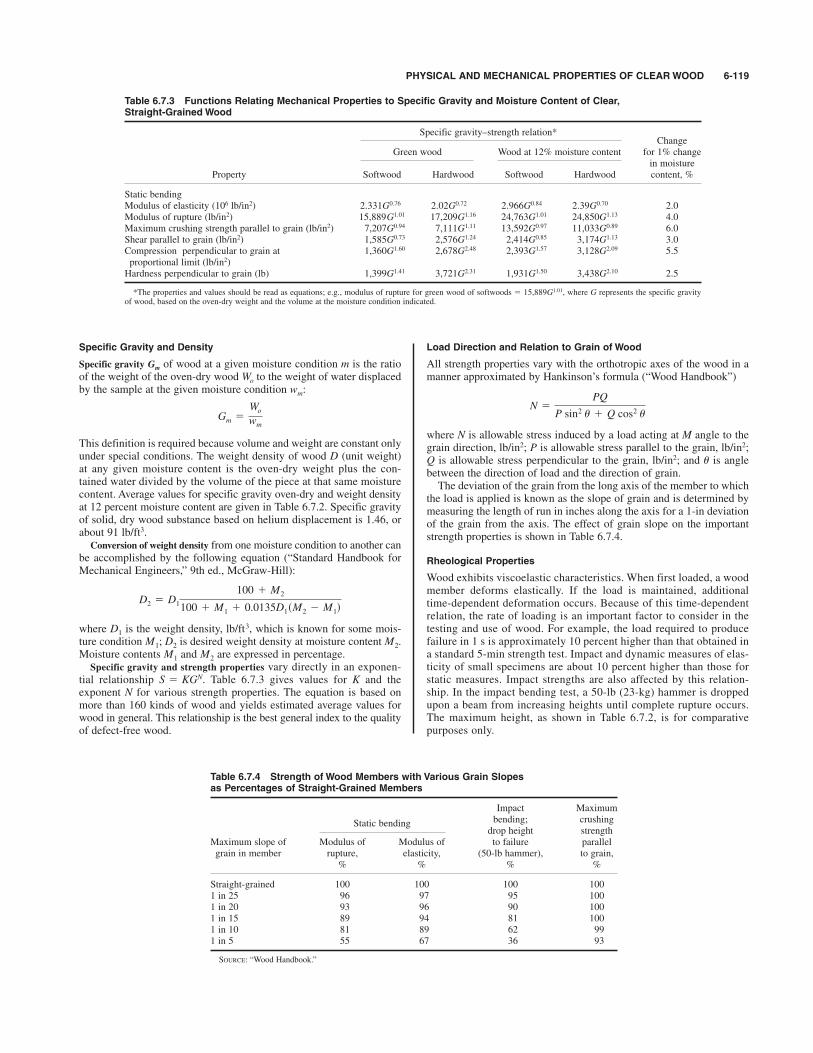
Specific Gravity and Density
Specific gravity of wood at a given moisture condition m is the ratioof the weight of the oven-dry wood to the weight of water displacedby the sample at the given moisture condition
This definition is required because volume and weight are constant onlyunder special conditions. The weight density of wood D (unit weight)at any given moisture content is the oven-dry weight plus the con-tained water divided by the volume of the piece at that same moisturecontent. Average values for specific gravity oven-dry and weight densityat 12 percent moisture content are given in Table 6.7.2. Specific gravityof solid, dry wood substance based on helium displacement is 1.46, orabout 91 lb/ft3.Conversion of weight density from one moisture condition to another can
be accomplished by the following equation (“Standard Handbook forMechanical Engineers,” 9th ed., McGraw-Hill):
where is the weight density, which is known for some mois-ture condition is desired weight density at moisture content Moisture contents and are expressed in percentage.Specific gravity and strength properties vary directly in an exponen-
tial relationship Table 6.7.3 gives values for K and theexponent N for various strength properties. The equation is based onmore than 160 kinds of wood and yields estimated average values forwood in general. This relationship is the best general index to the qualityof defect-free wood.
S 5 KGN.
M2M1
M2.M1; D2
lb/ft3,D1
D2 5 D1
100 1 M2
100 1 M1 1 0.0135D1sM2 2 M1d
Gm 5Wo
wm
wm:Wo
Gm
Load Direction and Relation to Grain of Wood
All strength properties vary with the orthotropic axes of the wood in amanner approximated by Hankinson’s formula (“Wood Handbook”)
where N is allowable stress induced by a load acting at M angle to thegrain direction, lb/in2; P is allowable stress parallel to the grain, lb/in2;Q is allowable stress perpendicular to the grain, lb/in2; and u is anglebetween the direction of load and the direction of grain.The deviation of the grain from the long axis of the member to which
the load is applied is known as the slope of grain and is determined bymeasuring the length of run in inches along the axis for a 1-in deviationof the grain from the axis. The effect of grain slope on the importantstrength properties is shown in Table 6.7.4.
Rheological Properties
Wood exhibits viscoelastic characteristics. When first loaded, a woodmember deforms elastically. If the load is maintained, additionaltime-dependent deformation occurs. Because of this time-dependentrelation, the rate of loading is an important factor to consider in thetesting and use of wood. For example, the load required to producefailure in 1 s is approximately 10 percent higher than that obtained ina standard 5-min strength test. Impact and dynamic measures of elas-ticity of small specimens are about 10 percent higher than those forstatic measures. Impact strengths are also affected by this relation-ship. In the impact bending test, a 50-lb (23-kg) hammer is droppedupon a beam from increasing heights until complete rupture occurs.The maximum height, as shown in Table 6.7.2, is for comparativepurposes only.
N 5PQ
P sin2 u 1 Q cos2 u
PHYSICAL AND MECHANICAL PROPERTIES OF CLEAR WOOD 6-119
Table 6.7.3 Functions Relating Mechanical Properties to Specific Gravity and Moisture Content of Clear,Straight-Grained Wood
Specific gravity–strength relation*Change
Green wood Wood at 12% moisture content for 1% changein moisture
Property Softwood Hardwood Softwood Hardwood content, %
Static bendingModulus of elasticity (106 lb/in2) 2.331G0.76 2.02G0.72 2.966G0.84 2.39G0.70 2.0Modulus of rupture (lb/in2) 15,889G1.01 17,209G1.16 24,763G1.01 24,850G1.13 4.0Maximum crushing strength parallel to grain (lb/in2) 7,207G0.94 7,111G1.11 13,592G0.97 11,033G0.89 6.0Shear parallel to grain (lb/in2) 1,585G0.73 2,576G1.24 2,414G0.85 3,174G1.13 3.0Compression perpendicular to grain at 1,360G1.60 2,678G2.48 2,393G1.57 3,128G2.09 5.5proportional limit (lb/in2)Hardness perpendicular to grain (lb) 1,399G1.41 3,721G2.31 1,931G1.50 3,438G2.10 2.5
*The properties and values should be read as equations; e.g., modulus of rupture for green wood of softwoods # 15,889G1.01, where G represents the specific gravityof wood, based on the oven-dry weight and the volume at the moisture condition indicated.
Table 6.7.4 Strength of Wood Members with Various Grain Slopes as Percentages of Straight-Grained Members
Impact Maximum
Static bending bending; crushingdrop height strength
Maximum slope of Modulus of Modulus of to failure parallel grain in member rupture, elasticity, (50-lb hammer), to grain,
% % % %
Straight-grained 100 100 100 1001 in 25 96 97 95 1001 in 20 93 96 90 1001 in 15 89 94 81 1001 in 10 81 89 62 991 in 5 55 67 36 93
SOURCE: “Wood Handbook.”
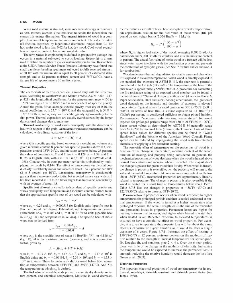
When solid material is strained, some mechanical energy is dissipatedas heat. Internal friction is the term used to denote the mechanism thatcauses this energy dissipation. The internal friction of wood is a com-plex function of temperature and moisture content. The value of inter-nal friction, expressed by logarithmic decrement, ranges from 0.1 forhot, moist wood to less than 0.02 for hot, dry wood. Cool wood, regard-less of moisture content, has an intermediate value.The term fatigue in engineering is defined as progressive damage that
occurs in a material subjected to cyclic loading. Fatigue life is a termused to define the number of cycles sustained before failure. Researchersat the USDA Forest Service Forest Products Laboratory have found thatsmall cantilever bending specimens subjected to fully reversed stresses,at 30 Hz with maximum stress equal to 30 percent of estimated staticstrength and at 12 percent moisture content and 758F (248C), have afatigue life of approximately 30 million cycles.
Thermal Properties
The coefficients of thermal expansion in wood vary with the structuralaxes. According to Weatherwax and Stamm (Trans. ASTM E 69, 1947,p. 421), the longitudinal coefficient for the temperature range &150 to$508C averages 3.39 % 106/ 8C and is independent of specific gravity.Across the grain, for an average specific gravity oven-dry of 0.46, theradial coefficient ar is 25.7 % 106/8C and the tangential at is 34.8 %106/8C. Both ar and at vary with specific gravity approximately to thefirst power. Thermal expansions are usually overshadowed by the largerdimensional changes due to moisture.Thermal conductivity of wood varies principally with the direction of
heat with respect to the grain. Approximate transverse conductivity can becalculated with a linear equation of the form
where G is specific gravity, based on oven-dry weight and volume at agiven moisture content M percent; for specific gravities above 0.3, tem-peratures around 758F (248C), and moisture contents below 25 percent,the values of constants A, B, and C are A # 0.129, B # 1.34, and C #0.028 in English units, with k in Btu ' in/(h ' ft2 ' F) (TenWolde et al.,1988). Conductivity in watts per meter per kelvin is obtained by multi-plying the result by 0.144. The effect of temperature on thermal con-ductivity is relatively minor and increases about 1 to 2 percent per 108F(2 to 3 percent per 108C). Longitudinal conductivity is considerablygreater than transverse conductivity, but reported values vary widely. Ithas been reported as 1.5 to 2.8 times larger than transverse conductivity,with an average of about 1.8.Specific heat of wood is virtually independent of specific gravity and
varies principally with temperature and moisture content. Wilkes foundthat the approximate specific heat of dry wood can be calculated with
where and for English units (specific heat inBtu per pound per degree Fahrenheit and temperature in degreesFahrenheit) or and for SI units [specific heat
in kJ/(kg ' K) and temperature in kelvins]. The specific heat of moistwood can be derived from
where cp,w is the specific heat of water [1 Btu/(lb ' 8F)], or 4.186 kJ/(kg ' K), M is the moisture content (percent), and A is a correctionfactor, given by
with b1 # $4.23 % 104, b2 # 3.12 % 105, and b3 # $3.17 % 105 in
English units; and b1#$0.06191, b2# 2.36% 104, and b3#$1.33%10$4 in SI units. These formulas are valid for wood below fiber satura-tion at temperatures between 458F (78C) and 2978F (1478C). And T isthe temperature at which is desired.The fuel value of wood depends primarily upon its dry density, mois-
ture content, and chemical composition. Moisture in wood decreases
cp0
A 5 Msb1 1 b2T 1 b3Md
cp 5
cp0 1 0.01Mcp,w
1 1 0.01M1 A
a1 5 0.00387a0 5 0.103
a1 5 0.000513a0 5 0.26
cp0 5 a0 1 a1T
k 5 GsB 1 CMd 1 A
the fuel value as a result of latent heat absorption of water vaporization.An approximate relation for the fuel value of moist wood (Btu perpound on wet weight basis) (2,326 Btu/lb # 1 J/kg) is
where is higher fuel value of dry wood, averaging 8,500 Btu/lb forhardwoods and 9,000 Btu/lb for conifers, and u is the moisture contentin percent. The actual fuel value of moist wood in a furnace will be lesssince water vapor interferes with the combustion process and preventsthe combustion of pyrolytic gases. (See Sec. 7 for fuel values and Sec. 4for combustion.)Wood undergoes thermal degradation to volatile gases and char when
it is exposed to elevated temperature. When wood is directly exposed tothe standard fire exposure of ASTM E 119, the char rate is generallyconsidered to be in/h (38 mm/h). The temperature at the base of thechar layer is approximately A procedure for calculatingthe fire resistance rating of an exposed wood member can be found inrecent editions of “National Design Specification” (American Forest &Paper Association, 2005 and later). Among other factors, the ignition ofwood depends on the intensity and duration of exposure to elevatedtemperatures. Typical values for rapid ignition are 570 to (300 to
). In terms of heat flux, a surface exposure to 1.1 Btu/ft2 (13kW/m2) per second is considered sufficient to obtain piloted ignition.Recommended “maximum safe working temperatures” for woodexposed for prolonged periods range from 150 to 2128F (65 to 1008C).Flame spread values as determined by ASTM E 84 generally rangefrom 65 to 200 for nominal 1-in- (25-mm-) thick lumber. Lists of flamespread index values for different species can be found in “WoodHandbook” and the Website of the American Wood Council. Flamespread can be reduced by impregnating the wood with fire-retardantchemicals or applying a fire-retardant coating.The reversible effect of temperature on the properties of wood is a
function of the change in temperature, moisture content of the wood,duration of heating, and property being considered. In general, themechanical properties of wood decrease when the wood is heated abovenormal temperatures and increase when it is cooled. The magnitude ofthe change is greater for green wood than for dry. When wood is frozen,the change in property is reversible; i.e., the property will return to thevalue at the initial temperature. At constant moisture content and belowabout mechanical properties are approximately linearlyrelated to temperature. The change in property is also reversible if thewood is heated for a short time at temperatures below about Table 6.7.5 lists the changes in properties at and
relative to those at Permanent loss in properties occurs when wood is exposed to higher
temperatures for prolonged periods and then is cooled and tested at nor-mal temperatures. If the wood is tested at a higher temperature afterprolonged exposure, the actual strength loss is the sum of the reversibleand permanent losses in properties. Permanent losses are higher forheating in steam than in water, and higher when heated in water thanwhen heated in air. Repeated exposure to elevated temperatures isassumed to have a cumulative effect on wood properties. For exam-ple, at a given temperature the property loss will be about the sameafter six exposure of 1-year duration as it would be after a singleexposure of 6 years. Figure 6.7.1 illustrates the effect of heating at
at 12 percent moisture content on the modulus of rup-ture relative to the strength at normal temperatures for spruce-pine-fir, Douglas-fir, and southern pine Over the 6-year period,there was little or no change in the modulus of elasticity. Increasingthe temperature would be expected to increase the permanent loss instrength; reducing the relative humidity would decrease the loss (seeGreen et al., 2003).
Electrical Properties
The important electrical properties of wood are conductivity (or its rec-iprocal, resistivity), dielectric constant, and dielectric power factor (seeJames, 1988).
2 3 4 s.
1508F s658Cd
688F s208Cd.1228F s508Cd2588F s2508Cd
1508F.
1508F s658Cd,
4008C7508F
5508F s3008Cd.11⁄2
HD
Hw 5 HDa100 2 u/7
100 1 ub
6-120 WOOD

PROPERTIES OF LUMBER PRODUCTS 6-121
Resistivity approximately doubles for each 108C decrease in temper-ature. As moisture content increases from zero to the fiber saturationpoint (FSP), the resistivity decreases by 1010 to 1013 times in an approx-imately linear relationship between the logarithm resistivity and mois-ture content. The resistivity is about 1014 to 1016 W ' m for oven-drywood and 103 to 104 W ' m for wood at FSP. As the moisture contentincreases up to complete saturation, the decrease in resistivity is a factorof only about 50. Wood species also affect resistivity (see James), andthe resistivity perpendicular to the grain is about twice that parallel tothe grain. Water-soluble salts (some preservatives and fire retardants)reduce resistivity by only a minor amount when the wood has 8 percentmoisture content or less, but they have a much larger effect when mois-ture content exceeds 10 to 12 percent.The dielectric constant of oven-dry wood ranges from about 2 to 5 at
room temperature, and it decreases slowly with increasing frequency.The dielectric constant increases as either temperature or moisture con-tent increases. There is a negative interaction between moisture and fre-quency: At 20 Hz, the dielectric constant may range from 4 for dry woodto 106 for wet wood; at 1 kHz, from 4 dry to 5,000 wet; and at 1 MHz,from about 3 dry to 100 wet. The dielectric constant is about 30 percentgreater parallel to the grain than perpendicular to it.The power factor of wood varies from about 0.01 for dry, low-density
woods to as great as 0.95 for wet, high-density woods. It is usually
greater parallel to the grain than perpendicular. The power factor isaffected by complex interactions of frequency, moisture content, andtemperature (James, 1975).The change in electrical properties of wood with moisture content has
led to the development of moisture meters for nondestructive estimation ofmoisture content. Resistance-type meters measure resistance between twopins driven into the wood. Dielectric-type meters depend on the correla-tion between moisture content and either dielectric constant or power fac-tor, and they require only contact with the wood surface, not penetration.
Wood in Relation to Sound
Transmission of sound and the vibrational properties in wood are functionsof a variety of factors. The speed of sound transmission is described
by the expression in which is the speed of sound in wood,in/s; E is the dynamic Young’s modulus, and is the density ofthe wood, (Pellerin and Ross, 2002). Various factors influencethe speed of sound transmission; two of the most important factors aregrain angle and the presence of degradation from decay. Hankinson’sformula, cited previously, adequately describes the relationshipbetween speed of sound transmission and grain angle. The dynamicmodulus is about 10 percent higher than the static value and variesinversely with moisture changes by approximately 1.3 percent for eachpercentage change in moisture content.Degradation from biological agents can significantly alter the speed at
which sound travels in wood. Speed of sound transmission values aregreatly reduced in severely degraded wood members. Sound transmissioncharacteristics of wood products are used in one form of nondestructivetesting to assess the performance characteristics of wood products.Because speed of sound transmission is a function of the extent ofdegradation from decay, this technique is used to estimate the extent ofsevere degradation in large timbers.
PROPERTIES OF LUMBER PRODUCTS
by Roland Hernandez and David W. Green
Visually Graded Structural Lumber
Stress-graded structural lumber is produced under two systems: visualgrading and machine grading. Visual structural grading is the oldeststress grading system. It is based on the premise that the mechanicalproperties of lumber differ from those of clear wood because manygrowth characteristics of lumber affect its properties; these characteris-tics can be seen and judged by eye (ASTM D 245). The principalgrowth feature affecting lumber properties are the size and location ofknots, sloping grain, and density.
slugs/in3rlb/in2;
nn 5 2E/r,
Table 6.7.5 Approximate Middle-Trends for the Reversible Effect of Temperature on Mechanical Properties of Clear Wood at Various MoistureConditions
Relative changein mechanical
Moistureproperty from 688F,
condition,%
Property % At $588F At &1228F
Modulus of elasticity parallel to grain 0 &11 $612 &17 $7
"FSP* &50 —Modulus of rupture 4 &18 $10
11–15 &35 $2018–20 &60 $25"FSP* &110 $25
Tensile strength parallel to grain 0–12 — $4Compressive strength parallel to grain 0 &20 $10
12–45 &50 $25Shear strength parallel to grain "FSP* — $25Compressive strength perpendicular to grain 0–16 — $20at proportional limit )10 — $35
*Moisture content higher than the fiber saturation point (FSP).TC # (TF $ 32)(0.55).
Fig. 6.7.1 Average residual MOR for solid-sawn 2 % 4 lumber exposed for var-ious times at 668C (1508F), 75 percent relative humidity and tested at 238C (738F),67 percent relative humidity. DF, Douglas-fir; So. Pine, southern pine; SPF,spruce–pine–fir.
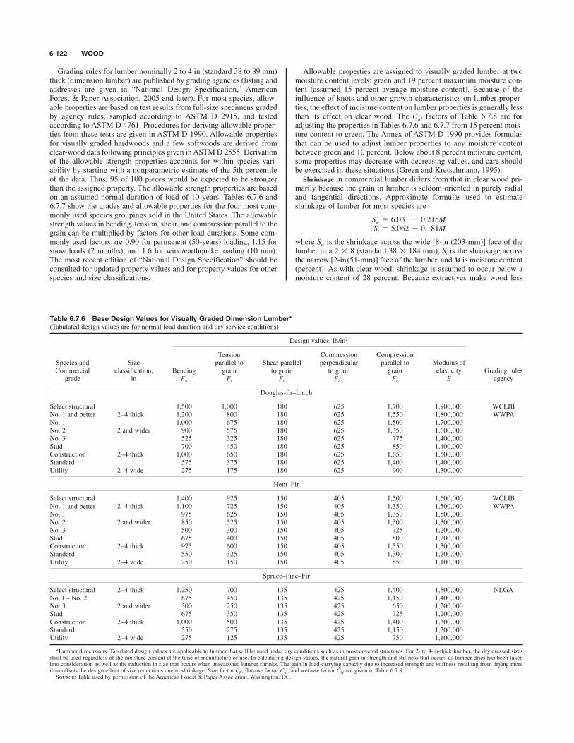
Grading rules for lumber nominally 2 to 4 in (standard 38 to 89 mm)thick (dimension lumber) are published by grading agencies (listing andaddresses are given in “National Design Specification,” AmericanForest & Paper Association, 2005 and later). For most species, allow-able properties are based on test results from full-size specimens gradedby agency rules, sampled according to ASTM D 2915, and testedaccording to ASTM D 4761. Procedures for deriving allowable proper-ties from these tests are given in ASTM D 1990. Allowable propertiesfor visually graded hardwoods and a few softwoods are derived fromclear-wood data following principles given in ASTM D 2555. Derivationof the allowable strength properties accounts for within-species vari-ability by starting with a nonparametric estimate of the 5th percentileof the data. Thus, 95 of 100 pieces would be expected to be strongerthan the assigned property. The allowable strength properties are basedon an assumed normal duration of load of 10 years. Tables 6.7.6 and6.7.7 show the grades and allowable properties for the four most com-monly used species groupings sold in the United States. The allowablestrength values in bending, tension, shear, and compression parallel to thegrain can be multiplied by factors for other load durations. Some com-monly used factors are 0.90 for permanent (50-years) loading, 1.15 forsnow loads (2 months), and 1.6 for wind/earthquake loading (10 min).The most recent edition of “National Design Specification” should beconsulted for updated property values and for property values for otherspecies and size classifications.
Allowable properties are assigned to visually graded lumber at twomoisture content levels: green and 19 percent maximum moisture con-tent (assumed 15 percent average moisture content). Because of theinfluence of knots and other growth characteristics on lumber proper-ties, the effect of moisture content on lumber properties is generally lessthan its effect on clear wood. The factors of Table 6.7.8 are foradjusting the properties in Tables 6.7.6 and 6.7.7 from 15 percent mois-ture content to green. The Annex of ASTM D 1990 provides formulasthat can be used to adjust lumber properties to any moisture contentbetween green and 10 percent. Below about 8 percent moisture content,some properties may decrease with decreasing values, and care shouldbe exercised in these situations (Green and Kretschmann, 1995).Shrinkage in commercial lumber differs from that in clear wood pri-
marily because the grain in lumber is seldom oriented in purely radialand tangential directions. Approximate formulas used to estimateshrinkage of lumber for most species are
where is the shrinkage across the wide [8-in (203-mm)] face of thelumber in a (standard ), is the shrinkage acrossthe narrow [2-in(51-mm)] face of the lumber, and M is moisture content(percent). As with clear wood, shrinkage is assumed to occur below amoisture content of 28 percent. Because extractives make wood less
St38 3 184 mm2 3 8Sw
St 5 5.062 2 0.181MSw 5 6.031 2 0.215M
CM
6-122 WOOD
Table 6.7.6 Base Design Values for Visually Graded Dimension Lumber*(Tabulated design values are for normal load duration and dry service conditions)
Design values, lb/in2
Tension Compression CompressionSpecies and Size parallel to Shear parallel perpendicular parallel to Modulus ofCommercial classification, Bending grain to grain to grain grain elasticity Grading rules
grade in Fb Ft Fv Fc' Fc E agency
Douglas-fir–Larch
Select structural 1,500 1,000 180 625 1,700 1,900,000 WCLIBNo. 1 and better 2–4 thick 1,200 800 180 625 1,550 1,800,000 WWPANo. 1 1,000 675 180 625 1,500 1,700,000No. 2 2 and wider 900 575 180 625 1,350 1,600,000No. 3 525 325 180 625 775 1,400,000Stud 700 450 180 625 850 1,400,000Construction 2–4 thick 1,000 650 180 625 1,650 1,500,000Standard 575 375 180 625 1,400 1,400,000Utility 2–4 wide 275 175 180 625 900 1,300,000
Hem–Fir
Select structural 1,400 925 150 405 1,500 1,600,000 WCLIBNo. 1 and better 2–4 thick 1,100 725 150 405 1,350 1,500,000 WWPANo. 1 975 625 150 405 1,350 1,500,000No. 2 2 and wider 850 525 150 405 1,300 1,300,000No. 3 500 300 150 405 725 1,200,000Stud 675 400 150 405 800 1,200,000Construction 2–4 thick 975 600 150 405 1,550 1,300,000Standard 550 325 150 405 1,300 1,200,000Utility 2–4 wide 250 150 150 405 850 1,100,000
Spruce–Pine–Fir
Select structural 2–4 thick 1,250 700 135 425 1,400 1,500,000 NLGANo. l – No. 2 875 450 135 425 1,150 1,400,000No. 3 2 and wider 500 250 135 425 650 1,200,000Stud 675 350 135 425 725 1,200,000Construction 2–4 thick 1,000 500 135 425 1,400 1,300,000Standard 550 275 135 425 1,150 1,200,000Utility 2–4 wide 275 125 135 425 750 1,100,000
*Lumber dimensions: Tabulated design values are applicable to lumber that will be used under dry conditions such as in most covered structures. For 2- to 4-in-thick lumber, the dry dressed sizesshall be used regardless of the moisture content at the time of manufacture or use. In calculating design values, the natural gain in strength and stiffness that occurs as lumber dries has been takeninto consideration as well as the reduction in size that occurs when unseasoned lumber shrinks. The gain in load-carrying capacity due to increased strength and stiffness resulting from drying morethan offsets the design effect of size reductions due to shrinkage. Size factor CF, flat-use factor Cfu, and wet-use factor CM are given in Table 6.7.8.SOURCE: Table used by permission of the American Forest & Paper Association, Washington, DC.

PROPERTIES OF LUMBER PRODUCTS 6-123
Table 6.7.7 Design values for Visually Graded Southern Pine Dimension Lumber*(Tabulated design values are for normal load duration and dry services conditions)
Design values, lb/in2
Tension Shear Compression CompressionSize parallel to parallel to perpendicular parallel to Modulus of
classification, Bending grain grain to grain grain elasticity Grading rulesCommercial grade in Fb Ft Fv Fc' Fc E agency
Dense select structural 2–4 thick 3,050 1,650 175 660 2,250 1,900,000 SPIBSelect structural 2,850 1,600 175 565 2,100 1,800,000Nondense select structural 2–4 wide 2,650 1,350 175 480 1,950 1,700,000No. 1 dense 2,000 1,100 175 660 2,000 1,800,000No. 1 1,850 1,050 175 565 1,850 1,700,000No. 1 nondense 1,700 900 175 480 1,700 1,600,000No. 2 dense 1,700 875 175 660 1,850 1,700,000No. 2 1,500 825 175 656 1,650 1,600,000No. 2 nondense 1,350 775 175 480 1,600 1,400,000No. 3 and stud 850 475 175 565 975 1,400,000
Construction 2–4 thick 1,100 625 175 565 1,800 1,500,000Standard 625 350 175 565 1,500 1,300,000Utility 4 wide 300 175 175 565 975 1,300,000
Dense select structural 2–4 thick 2,700 1,500 175 660 2,150 1,900,000Select structural 2,550 1,400 175 565 2,000 1,800,000Nondense select structural 5–6 wide 2,350 1,200 175 480 1,850 1,700,000No. 1 dense 1,750 950 175 660 1,900 1,800,000No. 1 1,650 900 175 565 1,750 1,700,000No. 1 nondense 1,500 800 175 480 1,600 1,600,000No. 2 dense 1,150 775 175 660 1,750 1,700,000No. 2 1,250 725 175 565 1,600 1,600,000No. 2 nondense 1,150 675 175 480 1,500 1,400,000No. 3 and stud 750 425 175 565 925 1,400,000
Dense select structural 2–4 thick 2,450 1,350 175 660 2,050 1,900,000Select structural 2,300 1,300 175 565 1,900 1,800,000Nondense select structural 8 wide 2,100 1,100 175 480 1,750 1,700,000No. 1 dense 1,650 875 175 660 1,800 1,800,000No. 1 1,500 825 175 565 1,650 1,700,000No. 1 nondense 1,350 725 175 480 1,550 1,600,000No. 2 dense 1,400 675 175 660 1,700 1,700,000No. 2 1,200 650 175 565 1,550 1,600,000No. 2 nondense 1,100 600 175 480 1,450 1,400,000No. 3 and stud 700 400 175 565 875 1,400,000
Dense select structural 2–4 thick 2,150 1,200 175 660 2,000 1,900,000Select structural 2,050 1,100 175 565 1,850 1,800,000Nondense select structural 10 wide 1,850 950 175 480 1,750 1,700,000No. 1 dense 1,450 775 175 660 1,750 1,800,000No. 1 1,300 725 175 565 1,600 1,700,000No. 1 nondense 1,200 650 175 480 1,500 1,600,000No. 2 dense 1,200 625 175 660 1,650 1,700,000No. 2 1,050 575 175 565 1,500 1,600,000No. 2 nondense 950 550 175 480 1,400 1,400,000No. 3 and stud 600 325 175 565 850 1,400,000
Dense select structural 2–4 thick 2,050 1,100 175 660 1,950 1,900,000Select structural 1,900 1,050 175 565 1,800 1,800,000Nondense select structural 12 wide 1,750 900 175 480 1,700 1,700,000No. 1 dense 1,350 725 175 660 1,700 1,800,000No. 1 1,250 675 175 565 1,600 1,700,000No. 1 nondense 1,150 600 90 480 1,500 1,600,000No. 2 dense 1,150 575 90 660 1,600 1,700,000No. 2 975 550 90 565 1,450 1,600,000No. 2 nondense 900 525 90 480 1,350 1,400,000No. 3 and stud 575 325 90 565 825 1,400,000
*For size factor CF appropriate size adjustment factors have already been incorporated in the tabulated design values for most thicknesses of southern pine dimension lumber. For dimension lum-ber 4 in thick, 8 in and wider, tabulated bending design values Fb shall be permitted to be multiplied by the size factor CF # 1.1. For dimension lumber wider than 12 in, tabulated bending, tension,and compression parallel-to-grain design values for 12-in-wide lumber shall be multiplied by the size factor CF # 0.9. Repetitive member factor Cr, flat-use factor Cfu, and wet-service factor CM aregiven in Table 6.7.8.SOURCE: Table used by permission of the American Forest & Paper Association, Washington, DC.

hygroscopic, less shrinkage is expected in redwood, western redcedar,and northern white cedar (Green, 1989).The reversible effect of temperature on lumber properties appears
to be similar to that on clear wood. For simplicity, “National DesignSpecification” uses conservative factors to account for reversible
reductions in properties as a result of heating to 1508F(658C) or less(Table 6.7.9). No increase in properties is taken for temperatures colderthan normal because in practice it is difficult to ensure that the woodtemperature remains consistently low. Permanent effects of temperatureare not given in “National Design Specification” (see Green et al., 2003).
6-124 WOOD
Table 6.7.8 Adjustment Factors
Size factor CF for Table 6.7.6 (Douglas-Fir–Larch, Hem-Fir, Spruce-Pine-Fir)
Tabulated bending, tension, and compression parallel to grain design values for dimension lumber 2 to 4 inthick shall be multiplied by the following size factors:
Fbthickness, in
Grades Width, in 2 & 3 4 Ft Fc
Select structural 2, 3, and 4 1.5 1.5 1.5 1.15No. 1 and better 5 1.4 1.4 1.4 1.1No. 1, no. 2, no. 3 6 1.3 1.3 1.3 1.1
8 1.2 1.3 1.2 1.0510 1.1 1.2 1.1 1.012 1.0 1.1 1.0 1.0
14 and wider 0.9 1.0 0.9 0.9Stud 2, 3, and 4 1.1 1.1 1.1 1.05
5 and 6 1.0 1.0 1.0 1.0Construction and standard 2, 3, and 4 1.0 1.0 1.0 1.0Utility 4 1.0 1.0 1.0 1.0
2 and 3 0.4 — 0.4 0.6
Repetitive-member factor Cr for Tables 6.7.6 and 6.7.7
Bending design values Fb for dimension lumber 2 to 4 in thick shall be multiplied by the repetitive factor Cr #
1.15, when such members are used as joists, truss chords, rafters, studs, planks, decking, or similar memberswhich are in contact or spaced not more than 24 in on centers, are not less than 3 in number, and are joined byfloor, roof, or other load-distributing elements adequate to support the design load.
Flat-use factor Cfu for Tables 6.7.6 and 6.7.7
Bending design values adjusted by size factors are based on edgewise use (load applied to narrow face).Whendimension lumber is used flatwise (load applied to wide face), the bending design value Fb shall also be mul-tiplied by the following flat-use factors:
Thickness, in
Width, in 2 and 3 4
2 and 3 1.0 —4 1.1 1.05 1.1 1.056 1.15 1.058 1.15 1.05
10 and wider 1.2 1.1
Wet-use factor CM for Tables 6.7.6 and 6.7.7
When dimension lumber is used where moisture content will exceed 19 percent for an extended period, designvalues shall be multiplied by the appropriate wet-service factors from the following table:
Fb Ft Fv Fc' Fc E
0.85* 1.0 0.97 0.67 0.8† 0.9
*When
†When
SOURCE: Used by permission of the American Forest & Paper Association, Washington, DC.
FcCF # 750 lb/in2, CM 5 1.0.
FbCF # 1150 lb/in2, CM 5 1.0.
Table 6.7.9 Temperature Factors Ctfor Short-Term Exposure (Reversible Effect)
In-serviceCt
Design values moisture conditions T 1008F 1008F ! T 1258F 1258F ! T 1508F
Ft, E Green or dry 1.0 0.9 0.9Fb, Fv, Fc, and Fc' 19% green 1.0 0.8 0.7
1.0 0.7 0.5
SOURCE: Table used by permission of the American Forest & Paper Association, Washington, DC.

PROPERTIES OF LUMBER PRODUCTS 6-125
Mechanically Graded Structural Lumber
Machine-stress-rated (MSR) lumber and machine-evaluated lumber(MEL) are two types of mechanically graded lumber. The three basiccomponents of both mechanical grading systems are (1) sorting andprediction of strength through machine-measured nondestructive deter-mination of properties coupled with visual assessment of growth char-acteristics, (2) assignment of allowable properties based upon strengthprediction, and (3) quality control to ensure that assigned properties arebeing obtained. Grade names for MEL start with an M designation.Grade “names” for MSR lumber are a combination of the allowablebending stress and the average modulus of elasticity; e.g., 1650f-1.4Emeans an allowable bending stress of 1,650 lb/in2 (11.4 MPa) and mod-ulus of elasticity of 1.4 % 106 lb/in2 (9.7 GPa). Selected grades ofmechanically graded lumber and their allowable properties are given inTable 6.7.10. Additional grades are available (see AF&PA, 2005).
Structural Composite Lumber
Types of Structural Composite Lumber Structural composite lum-ber refers to several types of reconstituted products that have beendeveloped to meet the demand for high-quality material for the manu-facture of engineered wood products and structures. Two distinct typesare commercially available: laminated veneer lumber (LVL) and paral-lel-strand lumber (PSL).Laminated veneer lumber is manufactured from layers of veneer
with the grain of all the layers parallel. This contrasts with plywood,which consists of adjacent layers with the grain perpendicular. Mostmanufacturers use sheets of - to -in-(2.5- to 4.2-mm-) thick veneer.These veneers are stacked up to the required thickness and may be laidend to end to the desired length with staggered end joints in the veneer.Waterproof adhesives are generally used to bond the veneer underpressure. The resulting product is a billet of lumber that may be up to
in (44 mm) thick, 4 ft (1.2 m) wide, and 80 ft (24.4 m) long. Thebillets are then ripped to the desired width and cut to the desired length.The common sizes of LVL closely resemble those of sawn dimensionlumber.Parallel-strand lumber is manufactured from strands or elongated
flakes of wood. One North American product is made from veneer clippedto in (13 mm) wide and up to 8 ft (2.4 m) long. Another product is madefrom elongated flakes and technology similar to that used to produceoriented strandboard. A third product is made from mats of intercon-nected strands crushed from small logs that are assembled into thedesired configuration. All the products use waterproof adhesive that iscured under pressure. The size of the product is controlled during man-ufacture through adjustments in the amount of material and pressureapplied. Parallel-strand lumber is commonly available in the same sizesas structural timbers or lumber.
Properties of Structural Composite Lumber Standard design val-ues have not been established for either LVL or PSL. Rather, standardprocedures are available for developing these design values (ASTM D5456). Commonly, each manufacturer follows these procedures andsubmits supporting data to the appropriate regulatory authority toestablish design properties for the product. Thus, design informationfor LVL and PSL varies among manufacturers and is given in theirproduct literature. Generally the engineering design properties com-pare favorably with or exceed those of high-quality solid dimensionlumber. Example design values accepted by U.S. building codes aregiven in Table 6.7.11.
Glued-Laminated Timber
Structural glued-laminated timber (glulam) is an engineered, stress-rated product of a timber laminating plant. It is comprised of assembliesof suitably selected and prepared wood laminations bonded togetherwith adhesives. The grain of all laminations is approximately parallellongitudinally. Individual laminations are typically made from nominal2-in- (standard 38-mm-) thick lumber when used for straight or slightlycambered members, and nominal 1-in- (standard 19-mm-) thick lumberwhen used for curved members. Individual lamination pieces may be
1⁄2
11⁄4
1⁄61⁄10
joined end to end to produce laminated timbers much longer than thelaminating stock itself. Pieces may also be placed or glued edge to edgeto make members wider than the input stock. Straight members up to140 ft (42 m) long and more than 7 ft (2.1 m) deep have been manu-factured, with size limitations generally resulting from transportationconstraints. Curved members have been used in domed structures span-ning over 500 ft (152 m).The arrangement of lumber grades in the laminated cross section
depends on the anticipated loading parallel or perpendicular to thewide faces of the laminations. When loads are applied perpendicularto the wide faces of the laminations, referred to as horizontally lam-inated, glulam cross sections are typically designed as bending com-binations. Bending combinations have higher-grade laminations in theouter top and bottom layers to carry the highest stresses and lower-grade laminations in the core layers where stresses are minimal. Insituations where all laminations are subjected to the same load, suchas compression, tension, or in bending with loads applied parallel tothe wide faces of the laminations (vertically laminated), glulam crosssections are typically designed as axial combinations. Axial combina-tions typically have the same lumber grade throughout the crosssection.
Manufacture Glulam members used in structural applications inthe United States must be manufactured by a laminating plant thatmeets the requirements of the national standard, ANSI A190.1. Thisstandard contains requirements for production, testing, and certificationof the product. Plants meeting these requirements can place their prod-uct quality mark on the glulam, which contains vital informationregarding the type, species, and properties of the glulam combination.Figure 6.7.2 shows examples of glulam product quality marks anddescribes the features required in the mark.Manufacturing standards cover many softwoods and hardwoods;
Douglas-fir and southern pine are the most commonly used softwoodspecies. Glulam members can be used in either dry- or wet-use condi-tions. Dry use, which is defined as a condition resulting in a moisturecontent of 16 percent or less, permits manufacturing with nonwater-proof adhesives; however, nearly all manufacturers in North Americause waterproof adhesives exclusively. For wet-use conditions, thesewaterproof adhesives are required. For wet-use conditions in which themoisture content is expected to exceed 20 percent, pressure preservativetreatment is recommended (AWPA C28). Lumber can be pressure-treatedwith water-based preservatives prior to gluing, provided that specialprocedures are followed in the manufacture. For treatment after gluing,oil-based preservatives are generally recommended.Glulam is generally manufactured at moisture content below 16 per-
cent. For most dry-use applications, it is important to protect the glulamtimber from increases in moisture content. End sealers, surface sealers,primer coats, and wrapping may be applied at the manufacturing plantto provide protection from changes in moisture content. Protection willdepend upon the final use and finish of the timber.Special precautions are necessary during handling, storage, and erec-
tion to prevent structural damage to glulam members. Padded or non-marring slings are recommended; cable slings or chokers should beavoided unless proper blocking protects the members. Technical manu-als on transit, storage, and erection of glulam members are provided byboth AITC and APA-EWS.
Design Glulam members are available in standard sizes with stan-dardized design properties. The following standard widths are estab-lished to match the widths of standard sizes of lumber, less an allowableamount for finishing the edges of the manufactured beams:
3 or 3 in (76 or 79 mm)5 or 5 in (127 or 130 mm)6 in (171 mm)8 or 8 in (216 or 222 mm)10 or 10 in (267 or 273 mm)
Standard beam depths are common multiples of lamination thickness ofeither 1 or 1 in (35 or 38 mm). There are no standard beam lengths,although most uses will be on spans where the length is from 10 to
1⁄23⁄8
3⁄41⁄2
3⁄41⁄2
3⁄4
1⁄8
1⁄8

6-126 WOOD
Table 6.7.10 Design Values for Mechanically Graded Dimension Lumber (Tabulated design values are for normal load duration and dry service conditions.)
Design values, lb/in2
Tension CompressionSpecies and Size classification, parallel parallel Modulus of
commercial grade in Bending to grain to grain elasticity Grading rules agency
Machine-stress-rated lumber
900f-1.0E 900 350 1,050 1,000,000 WCLIB, WWPA, NELMA, NSLB1200f-1.2E 1,200 600 1,400 1,200,000 NLGA, WCLIB, WWPA, NELMA, NSLB1250f-1.4E 1,250 800 1,475 1,400,000 WCLIB1350f-1.3E 1,350 750 1,600 1,300,000 NLGA, WCLIB, WWPA, NELMA, NSLB1400f-1.2E 1,400 800 1,600 1,200,000 NLGA1450f-1.3E 1,450 800 1,625 1,300,000 NLGA, WCLIB, WWPA, NELMA, NSLB1450f-1.5E 1,450 875 1,625 1,500,000 WCLIB1500f-1.4E 1,500 900 1,650 1,400,000 NLGA, WCLIB, WWPA, NELMA, NSLB1600f-1.4E 1,600 950 1,675 1,400,000 NLGA, WWPA1650f-1.3E 1,650 1,020 1,700 1,300,000 NLGA, SPIB, WCLIB, WWPA, NELMA, NSLB1650f-1.5E 1,650 1,020 1,700 1,500,000 WCLIB, WWPA1650f-1.6E-1075ft 1,650 1,075 1,700 1,600,000 WCLIB1650f-1.6E 1,650 1,175 1,700 1,600,000 WCLIB1650f-1.8E 1,650 1,020 1,750 1,800,000 WCLIB1700f-1.6E 1,700 1,175 1,725 1,600,000 WCLIB1750f-2.0E 1,750 1,125 1,725 2,000,000 NLGA1800f-1.5E 1,800 1,300 1,750 1,500,000 NLGA, SPIB, WCLIB, WWPA, NELMA, NSLB1800f-1.6E 1,800 1,175 1,750 1,600,000 WCLIB1800f-1.8E 1,800 1,200 1,750 1,800,000 SPIB, WWPA1950f-1.5E 2 & less in thickness 1,950 1,375 1,800 1,500,000 NLGA, SPIB, WCLIB, WWPA, NELMA, NSLB1950f-1.7E 1,950 1,375 1,800 1,700,000 NLGA2000f-1.6E 2,000 1,300 1,825 1,600,000 NLGA, SPIB, WCLIB, WWPA, NELMA, NSLB2100f-1.8E 2 & wider 2,100 1,575 1,875 1,800,000 NLGA, WWPA2250f-1.7E 2,250 1,750 1,925 1,700,000 NLGA, WCLIB, WWPA2250f-1.8E 2,250 1,750 1,925 1,800,000 NLGA, SPIB, WCLIB, WWPA, NELMA, NSLB2250f-1.9E 2,250 1,750 1,925 1,900,000 WCLIB, WWPA2250f-2.0E-1600ft 2,250 1,600 1,925 2,000,000 WCLIB, WWPA2250f-2.0E 2,250 1,750 1,925 2,000,000 NLGA, WWPA2400f-1.8E 2,400 1,925 1,975 1,800,000 NLGA, SPIB2400f-2.0E 2,400 1,925 1,975 2,000,000 NLGA, SPIB, WCLIB, WWPA, NELMA, NSLB2500f-2.2E 2,500 1,750 2,000 2,200,000 WCLIB2500f-2.2E-1925ft 2,500 1,925 2,000 2,200,000 WCLIB2550f-2.1E 2,550 2,050 2,025 2,100,000 NLGA, SPIB, WCLIB, WWPA, NELMA, NSLB2700f-2.0E 2,700 1,800 2,100 2,000,000 WCLIB2700f-2.2E 2,700 2,150 2,100 2,200,000 NLGA, SPIB, WCLIB, WWPA, NELMA, NSLB2850f-2.3E 2,850 2,300 2,150 2,300,000 NLGA, SPIB, WCLIB, WWPA, NELMA, NSLB3000f-2.4E 3,000 2,400 2,200 2,400,000 NLGA, SPIB
Machine-evaluated lumber
M-10 1,400 800 1,600 1,200,000 NLGA, SPIBM-11 1,550 850 1,675 1,500,000 NLGA, SPIBM-12 1,600 850 1,675 1,600,000 NLGA, SPIBM-13 1,600 950 1,675 1,400,000 NLGA, SPIBM-14 1,800 1,000 1,750 1,700,000 NLGA, SPIBM-15 1,800 1,100 1,750 1,500,000 NLGA, SPIBM-16 1,800 1,300 1,750 1,500,000 SPIBM-17 2 & less in thickness 1,950 1,300 2,050 1,700,000 SPIBM-18 2,000 1,200 1,825 1,800,000 SP1BM-19 2 & wider 2,000 1,300 1,825 1,600,000 NLGA, SPIBM-20 2,000 1,600 2,100 1,900,000 NLGA, SPIBM-21 2,300 1,400 1,950 1,900,000 NLGA, SPIBM-22 2,350 1,500 1,950 1,700,000 NLGA, SPIBM-23 2,400 1,900 1,975 1,800,000 NLGA, SPIBM-24 2,700 1,800 2,100 1,900,000 NLGA, SPIBM-25 2,750 2,000 2,100 2,200,000 NLGA, SPIBM-26 2,800 1,800 2,150 2,000,000 NLGA, SPIBM-27 3,000 2,000 2,400 2,100,000 SPIB
Lumber dimensions: Tabulated design values are applicable to lumber that will be used under dry conditions such as in most covered structures. For 2- to 4-in-thick lumber, the drydressed sizes shall be used regardless of the moisture content at the time of manufacture or use. In calculating design values, natural gain in strength and stiffness that occurs as lumberdries has been taken into consideration as well as reduction in size that occurs when unseasoned lumber shrinks. The gain in load-carrying capacity due to increased strength and stiffnessresulting from drying more than offsets the design of size reductions due to shrinkage. Shear parallel to grain Fv and compression perpendicular to grain Fc ': Design values for shearparallel to grain Fv1 and compression perpendicular to grain Fc' are identical to the design values given in Tables 6.7.6 and 6.7.7 for No. 2 visually graded lumber of the appropriatespecies. When the Fv or Fc' values shown on the grade stamp differ from the values shown in the tables, the values shown on the grade stamp shall be used for design. Modulus of elas-ticity E and tension parallel to grain Ft: For any given bending design value Fb, the average modulus of elasticity E and tension parallel to grain Ft design value may vary dependingupon species, timber source, or other variables. The E and Ft values included in the Fb and E grade designations are those usually associated with each Fb level. Grade stamps may showhigher or lower values if machine rating indicates the assignment is appropriate. When the E or Ft values shown on a grade stamp differ from the values in Table 6.7.10, the values shownon the grade stamp shall be used for design. The tabulated Fb and Fc values associated with the designated Fb value shall be used for design. Additional grades are available.SOURCE: Table used by permission of the American Forest & Paper Association, Washington, DC.

PROPERTIES OF STRUCTURAL PANEL PRODUCTS 6-127
20 times the depth. Technical publications containing allowable spansfor various loadings of standard sizes of beams are available from eitherAITC or APA-EWS.The design stresses for beams in bending for dry-use applications are
standardized in multiplies of 200 lb/in2 (1.4 MPa) with the range of2,000 to 3,000 lb/in2 (13.8 to 20.7 MPa). Modulus of elasticity valuesassociated with these design stresses in bending vary from 1.6 to 2.0 %106 lb/in2. A bending stress of 2,400 lb/in2 (16.5 MPa) and a modulus
of elasticity of 1.8 % 106 lb/in2 (12.4 GPa) are most commonly speci-fied, and the designer needs to verify the availability of beams withhigher values. Design properties must be adjusted for wet-use applica-tions. Detailed information on other design properties for beams as wellas design properties and procedures for arches and other uses is givenin “National Design Specification” (AF&PA).
Round Timbers
Round timbers in the form of poles, piles, or construction logs representsome of the most efficient uses of forest products because of the mini-mum of processing required. Poles and piles are generally debarked orpeeled, seasoned, graded, and treated with a preservative prior to use.Construction logs are often shaped to facilitate their use. See Table 6.7.12.
Poles The primary use of wood poles is to support utility and trans-mission lines. An additional use is for building construction. Each ofthese uses requires that the poles be pressure-treated with preservativesfollowing the applicable AWPA standard (C1). For utility structures, polelength may vary from 30 to 125 ft (9.1 to 38.1 m). Poles for building con-struction rarely exceed 30 ft (9.1 m). Southern pines account for the high-est percentage of poles used in the United States because of theirfavorable strength properties, excellent form, ease of treatment, and avail-ability. Douglas-fir and western redcedar are used for longer lengths;other species are also included in the ANSI O5.1 standard (ANSI 1992)that forms the basis for most pole purchases in the United States.Design procedures for the use of ANSI O5.1 poles in utility struc-
tures are described in the “National Electric Safety Code” (NESC). Forbuilding construction, design properties developed based on ASTM D2899 (see ASTM, 1995) are provided in “Timber Construction Manual”(AITC, 1994) or ASAE EP 388.
Piles Most piles used for foundations in the United States utilizeeither southern pine or Douglas-fir. Material requirements for timberpiles are given in ASTM D 25, and preservative treatment should fol-low the applicable AWPA standard (C1 or C3). Design stress and pro-cedures are provided in “National Design Specifications.”
Construction Logs Log buildings continue to be a popular form ofconstruction because nearly any available species of wood can be used.Logs are commonly peeled prior to fabrication into a variety of shapes.There are no standardized design properties for construction logs, andwhen they are required, log home suppliers may develop design prop-erties by following an ASTM standard (ASTM D 3957).
PROPERTIES OF STRUCTURAL PANELPRODUCTS
by Roland Hernandez
Structural panel products are a family of wood products made by bond-ing veneer, strands, particles, or fibers of wood into flat sheets. Themembers of this family are (1) plywood, which consists of productsmade completely or in part from wood veneer; (2) flakeboard, made
Table 6.7.11 Example Design Values for StructuralComposite Lumber
Modulus of HorizontalBending stress elasticity shear
Product lb/in2 MPa %103 lb/in2 GPa lb/in2 MPa
LVL 2,800 19.2 2,000 13.8 190 1.31PSL, type A 2,900 20.0 2,000 13.8 210 1.45PSL, type B 1,500 10.3 1,200 8.3 150 1.03
Fig. 6.7.2 Typical product quality stamps showing vital information for glulamcombination. 1, structural use of member (B, simple span bending member; C,compression member; T, tension member; CB, continuous or cantilevered spanbending member); 2, mill number; 3, species; 4, structural grade designation, indi-cating species, design bending strength and stiffness; 5, appearance grade desig-nation (framing, industrial, architectural, or premium); 6, identification ofconformance to ANSI A190.1 standard.
Table 6.7.12 Design Stresses for Selected Species of Round Timbers for BuildingConstruction
Design stress
Bending Compression Modulus of elasticity
Type of timber and species lb/in2 MPa lb/in2 MPa % 106 lb/in2 GPa
Poles*Southern pine and Douglas-fir 2,100 14.5 1,000 6.9 1.5 10.3Western redcedar 1,400 9.6 800 5.5 0.9 6.2
Piles†Southern pine 2,400 16.5 1,200 8.3 1.5 10.3Douglas-fir 2,450 16.9 1,250 8.6 1.5 10.3Red pine 1,900 13.1 900 6.2 1.3 8.8
*From “Timber Construction Manual” (AITC, 1994).†From “National Design Specification” (AF&PA, 2005).

from strands, wafers, or flakes; (3) particleboard, made from particles;and (4) fiberboard and hardboard, made from wood fibers. Plywood andflakeboard make up a large percentage of the panels used in structuralapplications such as roof, wall, and floor sheathing; thus, only thosetwo types will be described here.
Plywood
Plywood is the name given to a wood panel composed of relatively thinlayers or plies of veneer with the wood grain of adjacent layers at rightangles. The outside plies are called faces or face and back plies, the innerplies with grain parallel to that of the face and back are called cores orcenters, and the plies with grain perpendicular to that of the face andback are called crossbands. In four-ply plywood, the two center plies areglued with the grain direction parallel to each ply, making one centerlayer. Total panel thickness is typically not less than in (1.6 mm) ormore than 3 in (76 mm). Veneer plies may vary as to number, thickness,species, and grade. Stock plywood sheets usually measure 4 by 8 ft (1.2by 2.4 m), with the 8-ft (2.4-m) dimension parallel to the grain of theface veneers.The alternation of grain direction in adjacent plies provides plywood
panels with dimensional stability across their width. It also results infairly similar axial strength and stiffness properties in perpendiculardirections within the panel plane. The laminated construction results ina distribution of defects and markedly reduces splitting (compared tosolid wood) when the plywood is penetrated by fasteners.Two general classes of plywood, covered by separate standards, are
available: construction and industrial plywood, and hardwood and dec-orative plywood. Construction and industrial plywood is covered byProduct Standard PS 1-95; and hardwood and decorative plywood is
1⁄16
covered by ANSI/HPVA HP-1-2004. Each standard recognizes differentexposure durability classifications, which are primarily based on themoisture resistance of the glue used, but sometimes also address thegrade of veneer used.The exposure durability classifications for construction and indus-
trial plywood specified in PS-1 are: exterior, exposure 1, intermediateglue (exposure 2), and interior. Exterior plywood is bonded with exterior(waterproof) glue and is composed of C-grade or better veneers through-out. Exposure 1 plywood is bonded with exterior glue, but it may includeD-grade veneers. Exposure 2 plywood is made with glue of intermediateresistance to moisture. Interior-type plywood may be bonded withinterior, intermediate, or exterior (waterproof) glue. D-grade veneer isallowed on inner and back plies of certain interior-type grades.The exposure durability classifications for hardwood and decorative
plywood specified in ANSI/HPVA HP-1-2004 are, in decreasing orderof moisture resistance, as follows: technical (exterior), type I (exterior),type II (interior), and type III (interior). Hardwood and decorative ply-wood are not typically used in applications where structural perfor-mance is a prominent concern. Therefore, most of the remainingdiscussion of plywood performance will concern construction andindustrial plywood.A very significant portion of the market for construction and indus-
trial plywood is in residential construction. This market reality hasresulted in the development of performance standards for sheathing andsingle-layer subfloor or underlayment for residential construction byAPA–The Engineered Wood Association (APA–EWA). Plywood panelsconforming to these performance standards for sheathing are markedwith grade stamps such as those shown in Fig. 6.7.3 (example gradestamps are shown for different agencies). As seen in this figure, the
6-128 WOOD
(a) (b)
Fig. 6.7.3 Typical grade marks for (a) sheathing-grade plywood conforming to Product Standard PS 1-95 and (b) sheathing-gradestructural-use panel conforming to Product Standard PS 2-95. 1, conformance to indicated product standard; 2, recognition as a qualityassurance agency; 3, exposure durability classification; 4, thickness; 5, span rating; 6, conformance to performance-rated product; 7,manufacturer’s name or mill number; 8, grade of face and core veneers.

DURABILITY OF WOOD IN CONSTRUCTION 6-129
grade stamps must show (1) conformance to the plywood product stan-dards; (2) recognition as a quality assurance agency by the NationalEvaluation Services (NES), which is affiliated with the Council ofAmerican Building Officials; (3) exposure durability classification; (4)thickness of panel; (5) span rating, 32/16, which refers to the maximumallowable roof support spacing of 32 in (813 mm) and maximum floorjoist spacing of 16 in (406 mm); (6) conformance to the performance-rated standard of the agency; (7) manufacturer’s name or mill number;and (8) grades of face and core veneers.All hardwood plywood represented as conforming to American
National Standard ANSI/HPVA-HP-1-2004 is identified by one of twomethods: either marking each panel with the HPVA plywood gradestamp (Fig. 6.7.4) or including a written statement with this informationwith the order or shipment. The HPVA grade stamp shows (1) HPVAtrademark; (2) formaldehyde emission characteristics; (3) structuraldescription; (4) face species or finish type; (5) HPVA mill number; (6)veneer grade of face; (7) flame spread classification; (8) bondline type;and (9) standard that governs manufacture.The span-rating system for plywood was established to simplify
specification of plywood without resorting to specific structural engi-neering design. This system indicates performance without the need torefer to species group or panel thickness. It gives the allowable spanwhen the face grain is placed across supports.If design calculations are desired, a design guide is provided by APA-
EWA in “Plywood Design Specifications” (PDS, 2004). The designguide contains tables of grade stamp references, section properties, andallowable stresses for plywood used in construction of buildings andsimilar related structures. For the design and fabrication of curved pan-els, plywood-lumber beams, plywood stress-skin panels, plywood sand-wich panels, and all-plywood beams, information is available insupplements to the PDS standard from APA-EWA.If calculations for the actual physical and mechanical properties of
plywood are desired, formulas relating the properties of the particularwood species in the component plies to the laminated panel are providedin “Wood Handbook.” These formulas could be applied to plywood ofany species, provided the basic mechanical properties of the species areknown. Note, however, that the formulas yield predicted actual proper-ties (not design values) of plywood made of defect-free veneers.
Structural Flakeboards
Structural flakeboards are wood panels made from specially producedflakes—typically from relatively low-density species, such as aspenor pine—and bonded with an exterior-type water-resistant adhesive.Two major types of flakeboards are recognized, oriented strandboard(OSB) and waferboard. OSB is a flakeboard product made from wood
strands (long and narrow flakes) that are formed into a mat of threeto five layers. The outer layers are aligned in the long panel direction,while the inner layers may be aligned at right angles to the outer lay-ers or may be randomly aligned. In waferboard, a product madealmost exclusively from aspen wafers (wide flakes), the flakes arenot usually oriented in any direction, and they are bonded with anexterior-type resin. Because flakes are aligned in OSB, the bendingproperties (in the aligned direction) of this type of flakeboard aregenerally superior to those of waferboard. For this reason, OSB is thepredominant form of structural flakeboard. Panels commonly rangefrom 0.25 to 0.75 in (6 to 19 mm) thick and are 4 by 8 ft (1 by 2 m)in surface dimension. However, thicknesses up to 1.125 in (28.58mm) and surface dimensions up to 8 by 24 ft (2 by 7 m) are availableby special order.A substantial portion of the market for structural flakeboard is in res-
idential construction. For this reason, structural flakeboards are usuallymarketed as conforming to a product standard for sheathing or single-layer subfloor or underlayment and are graded as a performance-ratedproduct (PRP-108) similar to that for construction plywood. TheVoluntary Product Standard PS 2-95 is the performance standard forwood-based structural-use panels, which includes such products as ply-wood, composites, OSB, and waferboard. The PS 2-95 is not a replace-ment for PS 1-95, which contains necessary veneer grade and glue bondrequirements as well as prescriptive layup provisions and includesmany plywood grades not covered under PS 2-95.Design capacities of the APA–EWA performance-rated products,
which include OSB and waferboard, can be determined by using pro-cedures outlined in the APA–EWA Technical Note N375A. In this ref-erence, allowable design strength and stiffness properties, as well asnominal thicknesses and section properties, are specified based on thespan rating of the panel. Additional adjustment factors based on panelgrade and construction are provided.Because of the complex nature of structural flakeboards, formulas for
determining actual strength and stiffness properties, as a function of thecomponent material, are not available.
DURABILITY OF WOOD IN CONSTRUCTION
by Stan Lebow and Robert White
Biological Challenge
In the natural ecosystem, wood residues are recycled into the nutrientweb through the action of wood-degrading fungi, insects, and otherorganisms. In some circumstances, these same natural recyclers havethe potential to degrade wood used in construction. Termites and decayfungi are the most destructive, but other organisms, such as wood
Fig. 6.7.4 Grade stamp for hardwood plywood conforming to ANSI/HPVA HP-1-2004, 1, trademark of Hardwood Plywood andVeneer Association; 2, formaldehyde emission characteristics; 3, structural description; 4, face species or finish type; 5, HPVA millnumber; 6, veneer grade of face; 7, flame spread classification; 8, bondline type; 9, standard that governs manufacture.
boring beetles and carpenter ants, can be important in some regions.Several types of marine organisms can attack wood used in brackishwater and saltwater. If conditions are favorable for the survival of oneor more of these wood-destroying organisms, wood that has naturaldurability or that has been treated with preservatives should beemployed to ensure the integrity of the structure.
Conditions Favorable for Biodeterioration
Three environmental components govern the development of wood-degrading organisms within terrestrial wood construction: moisture,oxygen supply, and temperature. Of these, moisture seems most directlyinfluenced by design and construction practices. The oxygen supply isusually adequate except for materials submerged below water or deepwithin the soil, and wood-degrading organisms have evolved to survivein a wide range of temperatures. For these reasons, most of the follow-ing discussion will focus on relationships between wood moisture andpotential for wood deterioration.Decay fungi require free water within the wood cells (above 20 to
25 percent moisture content) to survive. Soil provides a continuingsource of moisture. Nondurable wood in contact with the ground willdecay most rapidly at the ground line where moisture from soil and thesupply of oxygen within the wood support growth of decay fungi. Deepwithin the soil, a limited supply of oxygen prevents growth of mostdecay fungi. As the distance above ground increases, the decreasingmoisture content limits fungal growth unless the wood is wettedthrough exposure to rain or from water entrapped as a consequence ofdesign or construction practices. Wood absorbs water through cut endsabout 11 times faster than through lateral surfaces. Consequently, decaydevelops first at the joints in aboveground construction.Extremely low oxygen content in wood submerged below water will
prevent growth of decay fungi, but other microorganisms can slowlycolonize submerged wood over decades or centuries of exposure. Thus,properties of such woods need to be reconfirmed when old, submergedstructures are retrofitted.Most wood-degrading insects also prefer moist wood, but their mois-
ture requirements vary somewhat by species. Subterranean termitesnative to the U.S. mainland establish a continuous connection with soilto maintain adequate moisture in wood that is being attacked aboveground. Formosan termites have the capacity to use sources of above-ground moisture without establishing a direct connection with the soil.Dry-wood termites survive only in tropical or neotropical areas withsufficiently high relative humidity to elevate the wood moisture contentto levels high enough to provide moisture for insect metabolism. Sometypes of wood-boring beetles, such as powder post beetles, can colonizewood with low moisture contents. Carpenter ants initially invade woodthat is moist or decayed, but may then expand into adjacent dry wood.
Methods for Protecting Wood
Protection with Good Design The most important aspect of pro-tecting wood in construction is use of designs that minimize moistureaccumulation. Many wood structures have endured for several hundredyears because of sound design and construction practices. In nearly allthose old buildings the wood has been kept dry by a barrier over thestructure (roof plus overhang), by maintaining a separation between theground and the wood elements (foundation), and by preventing accu-mulation of moisture in the structure (ventilation). Where Formosansubterranean termites occur, good designs and construction practicesthat eliminate sources of aboveground moisture are particularly impor-tant. Channeling of water from roof drains, collection of condensatefrom air conditioners, and proper installation of flashing are examplesof important considerations. Other design and construction practicesalso help to protect wood from insect attack. Chemical or physical bar-riers are often used to prevent subterranean termites from moving fromthe soil into a building. Many beetles attack only certain species orgroups of woods that may be used in speciality items such as joinery.When these species are used, it is important to use wood that is not pre-infested at the time of construction. Today’s engineered wood productswill last for centuries if good design practices are used. However, there
are many structures where it is impractical to prevent decay and insectattack simply through design. In these situations part of or all the struc-ture may need to be constructed with naturally durable wood species orwith wood that has been treated with preservatives.
Naturally Durable Wood The heartwood of old-growth trees of cer-tain species, such as bald cypress, redwood, cedars, and several whiteoaks, is naturally resistant or very resistant to decay fungi. Heartwoodof several other species, such as Douglas-fir, longleaf pine, easternwhite pine, and western larch, is moderately resistant to wood decayfungi. Some tropical species, such as ipe, are also imported because oftheir natural durability. Although decay resistance and resistance to ter-mite attack are correlated, not all species that are decay-resistant arealso resistant to termite attack. A more complete listing of naturallydurable woods is given in “Wood Handbook.” One limitation on the useof these species is that the durability is variable between trees and evenbetween pieces cut from a single tree. In addition, the supply of natu-rally durable species is limited relative to the demand for durable woodproducts. Consequently, other forms of protection, such as preservativetreatment, are more frequently used in current construction. Naturallydurable species are not effective in preventing marine borer attack, andpressure treatment with wood preservatives is required to protect woodused in marine or brackish waters.
Preservative Treatments Wood preservatives have been used forover a hundred years. They are broadly classified as either water type oroil type based on the chemical composition of the preservative and thesolvent used during the treating process. Each type of preservative hasadvantages and disadvantages, depending on the application. The mostcommon oil-type preservatives are creosote, pentachlorophenol, andcopper naphthenate. Because wood treated with oil-type preservativesmay be oily to the touch or have a noticeable odor, it is not usually usedfor applications involving frequent human contact or for inhabitedstructures. Oil-type preservatives may offer improved water repellencyand typically do not promote corrosion of fasteners. Water-basedpreservatives leave a dry, paintable surface and are commonly used totreat wood for residential applications such as decks and fences. Theyare primarily used to treat softwoods because hardwoods treated withthese preservatives may not be well protected from soft-rot attack. Untilrecently, the most widely used water-type preservative was chromatedcopper arsenate (CCA). However, CCA has now been voluntarilyphased out for most applications around residential areas and wherehuman contact is expected. More recent water-based preservatives, suchas alkaline copper quat or copper azole, rely primarily on copper to pro-tect the wood. Water-based wood preservatives can increase suscepti-bility to corrosion, and metal fasteners used with the treated woodshould be hot-dipped galvanized or stainless steel.Borates are another type of waterborne preservative that may be
used to treat interior building components for protection againstinsect attack. Borates should not be used where they are exposed tosoil or rainfall because they are readily leached from the wood. Innon-load-bearing applications such as exterior millwork around win-dows and doors, wood is usually protected with water-repellentpreservative treatments that are applied by nonpressure processes.Standards for preservative treatment are published by the AmericanWood-Preservers’ Association, and detailed information on woodpreservation is given in “Wood Handbook.” It is important to ensurethat wood is being treated to standard specifications. The U.S.Department of Commerce American Lumber Standard Committee(ALSC) accredits third-party inspection agencies for treated woodproducts. Updated lists of accredited agencies can be found on theALSC Website (www.alsc.org). If the wood has been treated to thesespecifications, it will have the quality mark or symbol of an ALSC-accredited inspection agency.
Protection from Weathering The combination of sunlight and otherweathering agents will slowly remove the surface fibers of wood prod-ucts. Removal of fibers can be greatly reduced by providing a wood fin-ish; if the finish is properly maintained, the removal of fibers can benearly eliminated. Information on wood finishes is available in Cassensand Feist, “Exterior Wood in the South.”
6-130 WOOD
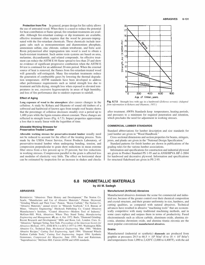
ABRASIVES 6-131
Protection from Fire In general, proper design for fire safety allowsthe use of untreated wood. When there is a need to reduce the potentialfor heat contribution or flame spread, fire-retardant treatments are avail-able. Although fire-retardant coatings or dip treatments are available,effective treatment often requires that the wood be pressure-impreg-nated with the fire-retardant chemicals. These chemicals include inor-ganic salts such as monoammonium and diammonium phosphate,ammonium sulfate, zinc chlorate, sodium tetraborate, and boric acid.Resin polymerized after impregnation into wood is used to obtain aleach-resistant treatment. Such amino resin systems are based on urea,melamine, dicyandiamide, and related compounds. An effective treat-ment can reduce the ASTM E 84 flame spread to less than 25 and showno evidence of significant progressive combustion when the ASTM E84 test is continued for an additional 20-min period. When the externalsource of heat is removed, the flames from fire-retardant-treated woodwill generally self-extinguish. Many fire-retardant treatments reducethe generation of combustible gases by lowering the thermal degrada-tion temperature. ASTM standards have been developed to addressother performance requirements such as initial strength loss due totreatment and kiln drying, strength loss when exposed to elevated tem-peratures in use, excessive hygroscopicity in areas of high humidity,and loss of fire performance due to outdoor exposure to rainfall.
Effect of Aging
Long exposure of wood to the atmosphere also causes changes in thecellulose. A study by Kohara and Okamoto of sound old timbers of asoftwood and hardwood of known ages from temple roof beams showsthat the percentage of cellulose decreases steadily over a period up to1,400 years while the lignin remains almost constant. These changes arereflected in strength losses (Fig. 6.7.5). Impact properties approximatea loss that is nearly linear with the logarithm of time.
Allowable Working Stresses for Preservative-Treated Lumber
Allowable working stresses for preservative-treated lumber usually neednot be reduced to account for the effect of the treating process. Testsmade by the USDA Forest Service, Forest Products Laboratory, ofpreservative-treated lumber when undergoing bending, tension, andcompression perpendicular to grain show reductions in mean extremefiber stress from a few percent up to 25 percent, but few reductionsin working stresses. Compression parallel to the grain is affected lessand modulus of elasticity very little. The effect on horizontal shearcan be estimated by inspection for an increase in shakes and checks
6.8 NONMETALLIC MATERIALSby Ali M. Sadegh
Fig. 6.7.5 Strength loss with age in a hardwood (Zelkowa serrata). (Adaptedfrom information in Kohara and Okamoto, 1955.)
ABRASIVES
REFERENCES: “Abrasives: Their History and Development,” The Norton Co.Searle, “Manufacture and Use of Abrasive Materials,” Pitman. Heywood,“Grinding Wheels and Their Uses,” Penton. “Boron Carbide,” The Norton Co.“Abrasive Materials,” annual review in “Minerals Yearbook,” U.S. Bureau ofMines. “Abrasive Engineering,” Hitchcock Publishing Co. Coated AbrasivesManufacturer’s Institute, “Coated Abrasives—Modern Tool of Industry,”McGraw-Hill. Wick, Abrasives; Where They Stand Today, ManufacturingEngineering and Management, 69, no. 4, Oct. 1972. Burls, “Diamond Grinding;Recent Research and Development,” Mills and Boon, Ltd., London. Coes, Jr.,“Abrasives,” Springer-Verlag, New York. Proceedings of the American Society forAbrasives Methods. 1971, ANSI B74.1 to B74.3 1977 to 1993. Washington MillsAbrasive Co., Technical Data, Mechanical Engineering, Mar. 1984. “ModernAbrasive Recipes,” Cutting Tool Engineering, April 1994. “Diamond WheelsFashion Carbide Tools,” Cutting Tool Engineering, August 1994. SyntheticGemstones, Compressed Air Magazine, June 1993. Krar and Ratterman,“Superabrasives,” McGraw-Hill. Current ASTM and ANSI standards.
Manufactured (Artificial) Abrasives
Manufactured abrasives dominate the scene for commercial and indus-trial use, because of the greater control over their chemical compositionand crystal structure, and their greater uniformity in size, hardness, andcutting qualities, as compared with natural abrasives. Technicaladvances have resulted in abrasive “machining tools” that are econom-ically competitive with many traditional machining methods, and insome cases replace and surpass them in terms of productivity. Fusedelectrominerals such as silicon carbide, aluminum oxide, alumina zir-conia, alumina chromium oxide, and alumina titania zirconia are themost popular conventional manufactured abrasives.
Grains
Manufactured (industrial or synthetic) diamonds are produced fromgraphite at pressures 29.5 to 66.5 % 106 N/m2 (8 to 18 % 105 lb/in2)and temperatures from 1,090 to 2,420*C (2,000 to 4,400*F), with the aid
after treatment. AWPA Standards keep temperatures, heating periods,and pressures to a minimum for required penetration and retention,which precludes the need for adjustment in working stresses.
COMMERCIAL LUMBER STANDARDS
Standard abbreviations for lumber description and size standards foryard lumber are given in “Wood Handbook.”Cross-sectional dimensions and section properties for beams, stringers,
joists, and planks are given in the “National Design Specification.”Standard patterns for finish lumber are shown in publications of the
grading rules for the various lumber associations.Information and specifications for construction and industrial plywood
are given in Product Standard PS 1-95 and in ANSI/HPVA HP-1-2004for hardwood and decorative plywood. Information and specificationsfor structural flakeboard are given in PS 2-95.

of metal catalysts. The shape of the crystal is temperature-controllable,with cubes (black) predominating at lower temperatures and octahedra(yellow to white) at higher. General Electric Co. produces syntheticsreaching 0.01 carat sizes and of quality comparable to natural diamondpowders. Grade MBG-11 (a blocky powder) is harder and tougher andis used for cutting wheels. Diamond hardness (placed at 10 on the Mohsscale) ranges from 5,500 to 7,000 on the Knoop scale. Specific gravityis 3.521.Recently, chemical vapor deposition (CVD) has produced diamond
vapors at ambient temperatures, which are then deposited on a substrateas a continuous film which may be from 1 to as much as 1,000 mmthick. Microscopically, CVD diamond is a dense polycrystalline struc-ture with discrete diamond grains. Deposition can be directly on toolssuch as wheels or other surfaces. CVD diamond can be polished to anyrequired surface texture and smoothness. Crystalline alumina, as chemically purified A12O3, is very adaptable
in operations such as precision grinding of sensitive steels. However,a tougher grain is produced by the addition of TiO2, Fe2O3, SiO2,ZrO2. The percentage of such additions and the method of coolingthe pig greatly influence grain properties. Advantage is taken of thisphenomenon to “custom” make the most desirable grain for particularmachining needs. Alumina crystals have conchoidal fracture, and thegrains when crushed or broken reveal sharp cutting edges and points.Average properties are: density ,3.8, coefficient of expansion ,0.81%10$5/*C (0.45 % 10$5/*F), hardness ,9 (Mohs scale), and melting tem-perature ,2,040*C (3,700*F). Applications cover the grinding of high-tensile-strength materials such as soft and hard steels, and annealedmalleable iron.Silicon carbide (SiC) corresponds to the mineral moissanite, and has
a hardness of about 9.5 (Mohs scale) or 2,500 (Knoop), and specificgravity 3.2. It is insoluble in acid and is infusible but decomposes above2,230*C (4,060*F). It is manufactured by fusing together coke and sandin an electric furnace of the resistance type. Sawdust is used also in thebatch and burns away, leaving passages for the carbon monoxide toescape. The grains are characterized by great brittleness. Abrasives ofsilicon carbide are best adapted to the grinding of low-tensile-strengthmaterials such as cast iron, brass, bronze, marble, concrete, stone, andglass. It is available under several trade names such as Carborundum,Carbolon, Crystolon.
Boron carbide (B4C), a black crystal, has a hardness of about 9.32(Mohs scale) or about 2,800 (Knoop), melts at about 2,460*C (4,478*F)but reacts with oxygen above 983*C (1,800*F), and is not resistant tofused alkalies. Boron carbide powder for grinding and lapping isobtainable in standard mesh sizes to 240, and to 800 in special finersizes. It is being used in loose grain form for the lapping of cemented-carbide tools. In the form of molded shapes, it is used for pressure blastnozzles, wire-drawing dies, bearing surfaces for gages, etc.Boron nitride (BN) when produced at extremely high pressures and
temperatures forms tiny reddish to black grains of cubic crystal struc-ture having hardness equal to diamond, and moreover is stable to1,930*C (3,500*F). Abrasive powders, such as Borazon, are used exten-sively for coated-abrasive applications as for grinding tool and diesteels and high-alloy steels, particularly where chemical reactivity ofdiamonds is a problem. Ease of penetration and free-cutting action min-imize heat generation, producing superior surface integrity.Crushed steel is made by heating high-grade crucible steel to white
heat and quenching in a bath of cold water. The fragments are thencrushed to sizes ranging from fine powder to in diam. They are clas-sified as diamond crushed steel, diamond steel, emery, and steelite, usedchiefly in the stone, brick, glass, and metal trades.Rouge and crocus are finely powdered oxide of iron used for buffing
and polishing. Rouge is the red oxide; crocus is purple.
Natural Abrasives
Diamond of the bort variety, crushed and graded into usable sizes andbonded with synthetic resin, metal powder, or vitrified-type bond, isused extensively for grinding tungsten- and tantalum-carbide cuttingtools, and glass, stone, and ceramics.
1⁄16
Corundum is a mineral composed chiefly of crystallized alumina(93 to 97 percent A12O3). It has been largely replaced by the manufac-tured variety.Emery, a cheap and impure form of natural corundum which has
been used for centuries as an abrasive, has been largely superseded bymanufactured aluminum oxide for grinding. It is still used to someextent in the metal- and glass-polishing trades.Garnet Certain deposits of garnet having a hardness between quartz
and corundum are used in the manufacture of abrasive paper. Quartz isalso used for this purpose. Garnet costs about twice as much as quartzand generally lasts proportionately longer.Buhrstones and millstones are generally made from cellular quartz.
Chasers (or stones running on edge) are also made from the samemineral.Natural oilstones, the majority being those quarried in Arkansas, are
of either the hard or the soft variety. The hard variety is used for toolsrequiring an extremely fine edge like those of surgeons, engravers, anddentists. The soft variety, more porous and coarser, is used for lessexacting applications.Pumice, of volcanic origin, is extensively used in leather, felt, and
woolen industries and in the manufacture of polish for wood, metal, andstone. An artificial pumice is made from sand and clay in five grades ofhardness, grain, and fineness.Infusorial earth or tripoli resembles chalk or clay in physical proper-
ties. It can be distinguished by absence of effervescence with acid, isgenerally white or gray in color, but may be brown or even black.Owing to its porosity, it is very absorptive. It is used extensively in pol-ishing powders, scouring soaps, etc., and, on account of its porousstructure, in the manufacture of dynamite as a holder of nitroglycerin,also as a nonconductor for steam pipes and as a filtering medium. It isalso known as diatomaceous silica.
Grinding Wheels For complete coverage and details see currentANSI/ASTM Standards D896 to D3808.
Vitrified Process In wheels, segments, and other abrasive shapes ofthis type, the abrasive grains are bonded with a glass or porcelainobtained by mixing the grains with such materials as clays and feldsparsin various proportions, molding the wheel, drying, and firing at a tem-perature of 1,370*C (2,500*F) approx. It is possible to manufacturewheels as large as 60 in diam by this process, and even larger wheelsmay be obtained by building up with segments. Most of the grindingwheels and shapes (segments, cylinders, bricks, etc.) now manufacturedare of the vitrified type and are very satisfactory for general grindingoperations.
Silicate Process Wheels and shapes of the silicate type are manu-factured by mixing the abrasive grain with sodium silicate (water glass)and fillers that are more or less inert, molding the wheel by tamping,and baking at a moderate temperature. Silicate bonded wheels are con-sidered relatively “mild acting” and, in the form of large wheels, arestill used to some extent for grinding-edge tools in place of the old-fashioned sandstone wheels.
Organic Bonded Wheels Organic bonds are used for high-speedwheels, and are equally well adapted to the manufacture of very thinwheels because of their flexibility compared with vitrified wheels.There are three distinct types in the group. The shellac process consistsof mixing abrasive grains with shellac, heating the mass until the shel-lac is viscous, stirring, cooling, crushing, forming in molds, and reheat-ing sufficiently to permit the shellac to set firmly upon cooling. Wheelsmade by this process are used for saw gumming, roll grinding, ball-raceand cam grinding, and in the cutlery trade. In the rubber process thebond is either natural or synthetic rubber. The initial mixture of grain,rubber, and sulfur (and such special ingredients as accelerators, fillers,and softeners) may be obtained by rolling or other methods. Havingformed the wheel, the desired hardness is then developed by vulcaniza-tion. Wheels can be made in a wide variety of grain combinations andgrades and have a high factor of safety as regards resistance to break-age in service. Wheels made by the rubber process are used for cutoffservice on wet-style machines, ball-race punchings, feed wheels andcenterless grinders, and for grinding stainless-steel billets and welds,
6-132 NONMETALLIC MATERIALS
ADHESIVES 6-133
which usually require a high-quality finish. With the resinoid process,the practice is to form the wheel by the cold-press process using a syn-thetic resin. After heating, the resultant bond is an insoluble, infusibleproduct of notable strength and resiliency. Resinoid bond is used for themajority of high-speed wheels in foundries, welding shops, and billetshops, and also for cutoff wheels. The rate of stock removal is generallyin direct proportion to the peripheral speed. Resinoid-bonded wheelsare capable of being operated at speeds as high as 2,900 m/min (9,500surface ft/min), as contrasted with 1,980 m/min (6,500 surface ft/min)for most vitrified bonds. Silicone-coated abrasives, such as Silkote are reported to resist dele-
terious coolant effects on the bond between resin and grain, because ofthe silicone’s ability to repel entry of coolant.The grain size or grit of a wheel is determined by the size or com-
bination of sizes of abrasive grain used. The Grinding Wheel Institutehas standardized sizes 8, 10, 12, 14, 16, 20, 24, 30, 36, 46, 54, 60, 70,80, 90, 100, 120, 150, 180, 200, 220, and 240. The finer sizes, knownas flours, are designated as 280, 320, 400, 500, 600, 800, 900, or as F,FF, FFF, and XF.The grade is the hardness or relative strength of bonding of a grind-
ing wheel. The wheel from which grain particles are easily brokenaway, causing it to wear rapidly, is called soft, and one that is able toretain its particles longer is called hard. The complete range of gradeletters used for the order of increasing hardness is
Soft Hard
A, B, C, D, E, F, G, H, I, J, K, L, M, N, O, P, Q, R, S, T, U, V, W, X, Y, Z
Table 6.8.1 provides a guide to surface finishes attainable with dia-mond grit.
synthetic adhesives serve for bond materials. Abrasive coatings can beclosed-coat, in which the abrasive grains are adjacent to one anotherwithout voids, or open-coat, in which the grains are set at a predeter-mined distance from one another. The flex of the backing is obtained bya controlled, directional, spaced backing of the adhesive bond.
Abrasive Waterjets
Such tough-to-cut materials as titanium, ceramics, metallic honeycombstructures, glass, graphite, and bonding compounds can be successfullycut with abrasive waterjets. Abrasive waterjets use pressurized water, upto 60 lb/in2, to capture solid abrasives by flow momentum, after whichthe mixture is expelled through a sapphire nozzle to form a highlyfocused, high-velocity cutting “tool.” Advantages of this cutting methodinclude: minimal dust, high cutting rates, multidirectional cutting capa-bility, no tool dulling, no deformation or thermal stresses, no fire haz-ards, ability to cut any material, small power requirements, avoidanceof delamination, and reduction of striation. (See also Sec. 13.)Abrasive waterjet cutting, however, has some limitations including
high noise level (80 to 100 dB), safety problems, low material removalrates, inability to machine blind holes or pockets, damage to acciden-tally exposed machine elements by the particles and/or high-pressurewater, and the size of the overall system.
Industrial Sharpening Stones
Sharpening stones come in several forms such as bench stones, files,rubbing bricks, slip stones, and specialties, and are made chiefly fromaluminum oxide, such as Alundum, or silicon carbide, such asCrystolon. Grit sizes of fine, medium, and coarse are available.
ADHESIVES
REFERENCES: Cagle (ed.), “Handbook of Adhesive Bonding,” McGraw-Hill.Bikerman, “The Science of Adhesive Joints,” Academic. Shields, “AdhesivesHandbook,” CRC Press (Division of The Chemical Rubber Co.). Cook,“Construction Sealants and Adhesives,” Wiley. Patrick, “Treatise on Adhesives,”Marcel Dekker. NASA SP-5961 (01) Technology Utilization, “ChemistryTechnology: Adhesives and Plastics,” National Technical Information Services,Virginia. Simonds and Church, “A Concise Guide to Plastics,” Reinhold. Lerner,Kotsher, and Sheckman, “Adhesives Red Book,” Palmerton Publishing Co., NewYork. Machine Design, June 1976. ISO 6354–1982. “1994 Annual Book ofASTM Standards,” vol. 15.06 (Adhesives). ANSI/ASTM Standards D896–D3808.Current ASTM and ANSI Standards.
Adhesives are substances capable of holding materials together in auseful manner by surface attachment. Some of the advantages and dis-advantages of adhesive bonding are as follows:
Advantages Ability to bond similar or dissimilar materials of dif-ferent thicknesses; fabrication of complex shapes not feasible by otherfastening means; smooth external joint surface; economic and rapidassembly; uniform distribution of stresses; weight reduction; vibrationdamping; prevention or reduction of galvanic corrosion; insulatingproperties.
Disadvantages Surface preparation; long cure times; optimumbond strength not realized instantaneously, service-temperature limita-tions; service deterioration; assembly fire or toxicity; tendency to creepunder sustained load.A broad scheme of classification is given in Table 6.8.2a.For the vocabulary of adhesives the reader should refer to ISO
6354–1982, and for standard definitions refer to ASTM D907–82.Procedures for the testing of adhesive strength viscosity, storage life,fatigue properties, etc. can be found in ANSI/ASTM D950–D3808.Thermoplastic adhesives are a general class of adhesives based upon
long-chained polymeric structure, and are capable of being softened bythe application of heat.Thermosetting adhesives are a general class of adhesives based upon
cross-linked polymeric structure, and are incapable of being softened oncesolidified. A recent development (1994) in cross-linked aromatic poly-esters has yielded a very durable adhesive capable of withstanding tem-peratures of 700*F before failing. It retains full strength through 400*F.
Coated Abrasives
Coated abrasives are “tools” consisting of an abrasive grit, a backing, andan adhesive bond. Grits are generally one of the manufactured varietylisted above, and are available in mesh sizes ranging from the coarsest at12 to the finest at 600. Backings can be cloth, paper, fiber, or combina-tions and are made in the form of belts and disks for poweroperated toolsand in cut sheets for both manual and power usage. Adhesive bondsconsist of two layers, a “make coat” and a “size coat.” Both natural and
Table 6.8.1 Guide to Surface Finish Attainable withDiamond Grit
Surface finish Recommended max
m in mmDOC* per pass
Grit size (AA) Ra in mm
80 26–36100 24–32105 18–30100S 16–26 0.4–0.8 0.001–0.002 25–50110120 16–18150 14–16180 12–14 0.25–0.50 0.0007–0.0010 17–25220 10–12240 8–10320 8 0.12–0.25 0.0004–0.000610–15400 7–8 0.08–0.15 0.0003–0.0005 8–1230–40 mm 720–30 6–7 0.05–0.10 0.0002–0.0004 5–10
610–20 5–68–166–12 3–54–8 2–4 0.013–0.025 0.00005–0.00007 1–23–6 20–2 1
* DOC # depth of cut.SOURCE: Cutting Tool Engineering, Aug. 1994.

It is likely that widespread applications for it will be found first in theautomotive and aircraft industries.Thermoplastic and thermosetting adhesives are cured (set, polymer-
ized, solidified) by heat, catalysis, chemical reaction, free-radical activ-ity, radiation, loss of solvent, etc., as governed by the particularadhesive’s chemical nature.Elastomers are a special class of thermoplastic adhesive possessing
the common quality of substantial flexibility or elasticity.Anaerobic adhesives are a special class of thermoplastic adhesive
(polyacrylates) that set only in the absence of air (oxygen). The twobasic types are: (1) machinery—possessing shear strength only, and (2)structural—possessing both tensile and shear strength.Pressure-sensitive adhesives are permanently (and aggressively) tacky
(sticky) solids which form immediate bonds when two parts are broughttogether under pressure. They are available as films and tapes as well ashot-melt solids.The relative performance of a number of adhesives is given in
Table 6.8.2b.For high-performance adhesive applications (engineering or machine
parts) the following grouping is convenient.
Thread locking Anaerobic acrylicHub mounting Anaerobic acrylic—compatible materials or
flow migration unimportant.Modified acrylic—large gaps or migrationmust be avoided.Epoxy—maximum strength at high tempera-tures
Bearing mounting Anaerobic acrylic—compatible materialsnecessary and flow into bearing area to beprevented.Modified acrylic—for lowest cost
Structural joining Epoxies and modified epoxies—for maximumstrength (highest cost)Acrylics—anaerobic or modified cyanacrylates
Gasketing Silicones—primarily anaerobic
Table 6.8.3 presents a sample of a number of adhesives (with practi-cal information) that are available from various sources. The table isadapted from the rather extensive one found in J. Shields, “AdhesivesHandbook,” CRC Press (Division of The Chemical Rubber Co.), 1970,by permission of the publisher. Domestic and foreign trade sources arelisted there (pages 332–340) and appear coded (in parentheses) in thesecond column. For other extensive lists of trade sources, the reader isreferred to Charles V. Cagle (ed.), “Handbook of Adhesive Bonding,”McGraw-Hill, and “Adhesives Red Book,” Palmerton Publishing Co.,New York.
BRICK, BLOCK, AND TILE
REFERENCES: Plummer and Reardon, “Principles of Brick Engineering, Handbookof Design,” Structural Clay Products Institute. Stang, Parsons, and McBurney,Compressive Strength of Clay Brick Walls, B. of S. Research Paper 108. Hunting,“Building Construction,” Wiley. Amrhein, “Reinforced Masonry EngineeringHandbook,” Masonry Institute of America. Simpson and Horrbin (eds.), “TheWeathering and Performance of Building Materials,” Wiley. SVCE and Jeffers(eds.), “Modern Masonry Panel Construction Systems,” Cahners Books (Divisionof Cahners Publishing Co.). ASTM Standards C67-C902. ANSI/ASTM StandardsC62-C455.
Brick
In the case of structural and road building material, a small unit, solidor practically so, commonly in the form of a rectangular prism, formed from inorganic, nonmetallic substances and hardened in its finishedshape by heat or chemical action. Note that the term is also used col-lectively for a number of such units, as “a carload of brick.” In the pre-sent state of the art, the term brick, when used without a qualifyingadjective, should be understood to mean such a unit, or a collection ofsuch units, made from clay or shale hardened by heat. When other sub-stances are used, the term brick should be suitably qualified unlessspecifically indicated by the context.It is recognized that unless suitably qualified, a brick is a unit of
burned clay or shale.
6-134 NONMETALLIC MATERIALS
Table 6.8.2a Classification of Adhesives
Origin and basic type Adhesive material
Natural Animal Albumen, animal glue (including fish), casein, shellac, beeswaxVegetable Natural resins (gum arabic, tragacanth, colophony, Canada balsam, etc.); oils and
waxes (carnauba wax, linseed oils); proteins (soybean); carbohydrates (starch,dextrins)
Mineral Inorganic materials (silicates, magnesia, phosphates, litharge, sulfur, etc.); mineralwaxes (paraffin); mineral resins (copal, amber); bitumen (including asphalt)
Synthetic Elastomers Natural rubber (and derivatives, chlorinated rubber, cyclized rubber, rubberhydrochloride)Synthetic rubbers and derivatives (butyl, polyisobutylene, polybutadiene blends(including styrene and acylonitrile), polyisoprenes, polychloroprene,polyurethane, silicone, polysulfide, polyolefins (ethylene vinyl chloride, ethylenepolypropylene)Reclaim rubbers
Thermoplastic Cellulose derivatives (acetate, acetate-butyrate, caprate, nitrate, methyl cellulose,hydroxy ethyl cellulose, ethyl cellulose, carboxy methyl cellulose)Vinyl polymers and copolymers (polyvinyl acetate, alcohol, acetal, chloride,polyvinylidene chloride, polyvinyl alkyl ethersPolyesters (saturated) [polystyrene, polyamides (nylons and modifications)]Polyacrylates (methacrylate and acrylate polymers, cyanoacrylates, acrylamide)Polyethers (polyhydroxy ether, polyphenolic ethers)Polysulfones
Thermosetting Amino plastics (urea and melamine formaldehydes and modifications)Epoxides and modifications (epoxy polyamide, epoxy bitumen, epoxypolysulfide, epoxy nylon)Phenolic resins and modifications (phenol and resorcinol formaldehydes,phenolic-nitrile, phenolic-neoprene, phenolic-epoxy)Polyesters (unsaturated)Polyaromatics (polyimide, polybenzimidazole, polybenzothiazole, polyphenylene)Furanes (phenol furfural)
SOURCE: Shields, “Adhesives Handbook,” CRC Press (Division of the Chemical Rubber Co.).
BRICK, BLOCK, AND TILE 6-135
Brick (Common) Any brick made primarily for building purposesand not especially treated for texture or color, but including clinker andoven-burn brick.
Brick (Facing) A brick made especially for facing purposes, usuallytreated to produce surface texture or made of selected clays or other-wise treated to produce the desired color.Brick are manufactured by the dry-press, the stiff-mud, or the soft-
mud process. The dry-press brick are made in molds under high pres-sure and from relatively dry clay mixes. Usually all six surfaces aresmooth and even, with geometrical uniformity. The stiff-mud brick aremade from mixes of clay or shale with more moisture than in the dry-press process, but less moisture than used in the soft-mud process. Theclay is extruded from an auger machine in a ribbon and cut by wiresinto the required lengths. These brick may be side-cut or end-cut,depending on the cross section of the ribbon and the length of the sec-tion cut off. The two faces cut by wires are rough in texture; the otherfaces may be smooth or artificially textured. The soft-mud process usesa wet mix of clay which is placed in molds under slight pressure.Brick are highly resistant to freezing and thawing, to attacks of acids
and alkalies, and to fire. They furnish good thermal insulation and goodinsulation against sound transference.Paving brick are made of clay or shale, usually by the stiff-mud or
dry-press process. Brick for use as paving brick are burned to vitrifica-tion. The common requirements are as follows: size, 8 % 2 % 4,8 % 3 % 3 , 8 % 3 % 4, with permissible variations of in ineither transverse dimension, and in in length. Although brick have always been used in construction, their use has
been limited, until recently, to resisting compressive-type loadings. Byadding steel in the mortar joints to take care of tensile stresses,reinforced brick masonry extends the use of brick masonry to additionaltypes of building construction such as floor slabs.
1⁄4
1⁄81⁄21⁄21⁄2
1⁄21⁄2
Sand-lime brick are made from a mixture of sand and lime, moldedunder pressure and cured under steam at 200*F. They are usually a lightgray in color and are used primarily for backing brick and for interiorfacing.Cement brick are made from a mixture of cement and sand, manufac-
tured in the same manner as sand-lime brick. In addition to their use asbacking brick, they are used where there is no danger of attack fromacid or alkaline conditions.Firebrick (see this section, Refractories).Specialty Brick A number of types of specialty brick are available
for important uses, particularly where refractory characteristics areneeded. These include alumina brick, silicon carbide brick, and boroncarbide brick.
Other Structural Blocks Important structural units which fall out-side the classic definition of brick are as follows: Concrete blocks aremade with portland cement as the basic binder. Often, these are referredto as concrete masonry units (CMUs). The choice of aggregate rangesfrom relatively dense aggregate such as small crushed stone, smallgravel, or coal cinders (the latter, if available) to light aggregate such assand, limestone tailings, or the like. Gypsum blocks are generally usedfor fire protection in non-load-bearing situations. Glass blocks areavailable where transparency is desired. Structural clay tile is widelyused in both load-bearing and non-load-bearing situations; a variety ofcomplex shapes are available for hollow-wall construction. For classifi-cation of all these products with respect to dimensions and specifica-tions for usage, the references should be consulted.Brick and block can come with porcelain glazed finish for appear-
ance, ease of cleaning, resistance to weathering, corrosion, etc.Brick panels (prefabricated brick walls) are economical and find
extensive use in modern high-rise construction. Such panels can be con-structed on site or in factories.
Table 6.8.2b Performance of Adhesive Resins(Rating 1 # poorest or lowest, 10 # best or highest)
Adherence to Resistance
Adhesive resin Paper Wood Metal Ceramics Rubbers Water Solvents Alkali Acids
Alkyd 6 7 5 6 7 7 2 2 5Cellulose acetate 4 3 1 3 5 2 3 1 3Cellulose acetate butyrate 3 3 1 4 5 2 3 I 3Cellulose nitrate 5 5 1 5 5 3 2 2 4
Ethyl cellulose 3 3 1 3 5 2 3 3 3Methyl cellulose 5 1 1 3 3 1 6 3 3Carboxy methyl cellulose 6 1 2 3 2 1 6 1 4Epoxy resin 10 10 8 8 8 8 9 9 8
Furane resin 8 7 1 8 7 8 9 10 8Melamine resin 10 10 2 2 2 7 9 5 5Phenolic resins 9 8 2 6 7 8 10 7 8Polyester, unsaturated 6 8 2 5 7 7 6 1 6
Polyethylacrylate 3 4 3 5 6 8 2 6 7Polymethylmethacrylate 2 3 2 3 6 8 3 8 7Polystyrene 1 3 2 2 5 8 1 10 8Polyvinylacetate 8 7 7 7 3 3 3 4 6
Polyvinyl alcohol 6 2 2 4 6 I 7 1 3Polyvinyl acetal 5 7 8 7 7 8 5 3 5Polyvinyl chloride 5 7 6 7 6 8 6 10 9Polyvinyl acetate chloride 6 8 6 7 5 8 5 9 9
Polyvinylidene copolymer 4 7 6 7 7 8 7 10 9Silicons T.S. 4 6 7 7 8 10 7 6 6Urethane T.S. 8 10 10 9 10 7 8 4 4Acrylonitrile rubber 3 6 8 6 9 7 5 8 8
Polybutene rubber 3 3 6 2 8 8 3 10 9Chlorinated rubber 3 5 7 4 7 6 3 10 9Styrene rubber 5 7 6 5 8 7 3 10 9
SOURCE: Adapted from Herbert R. Simonds and James M. Church, “A Concise Guide to Plastics,” 2d ed., Reinhold, 1963, with permission of the publisher.

6-136 NONMETALLIC MATERIALS
Table 6.8.3 Properties and Uses of Various Adhesives
ServiceCuring cycle, temp range,
Basic type time at temp *C Adherends Main uses Remarks
Animal
Animal (hide) Melted at 70–75*C. Sets on Paper, wood, textiles Woodworking, carpet May be thinned with watercooling materials, paper,
bookbindingAnimal (hide) & Applied as a melt at 60*C !60 Paper, cellulosic materials Bookbinding, stationery Cures to permanent flexibleplasticizers applications filmFish glue 1 h at 20*C 60 Wood, chipboard, paper General-purpose for porous Rapid setting. Good
materials flexibilityModerate resistance to water.High tack.
Casein Cold setting after 20-min Timber with moisture content Laminated timber arches and Full bond strength developedstanding period on mixing beams, plybox beams, and after seasoning period of
engineering timber work 48 hCasein & 60% latex Cold setting after 20-min Aluminum, wood, phenolic Bonding of dissimilar Flexible
standing period on mixing formaldehyde (rigid), materials to give flexible,leather, rubber water-resistant bond
Vegetable
Dextrine Air drying Paper, cardboard, leather, General-purpose glue for Medium drying period ofwood, pottery absorbent materials 2–3h
Dextrine-starch blend Applied above 15*C air 48 Cellulosic materials, Labeling, carton sealing, Fast setting. May be diluteddrying cardboard, paper spiral-tube winding with water
Gum arabic Cold setting Paper, cardboard Stationery uses Fast drying
Mineral
Silicate 8 h at 20*C 10–430 Asbestos, magnesia Lagging asbestos cloth on Unsuitable where moisture: high-temperature insulation not recommended for glass
or painted surfacesSilicate with Dried at 80*C before $180–1,500 Asbestos, ceramics, General-purpose cement for Resistant to oil, gasoline, and chinaclay filler exposure to heat brickwork, glass, silver, bonding refractory materials weak acids
aluminum, steel (mild)- and metals. Furnace repairssteel and gastight jointing of pipe
work. Heat-insulating materials
Sodium silicate Dried at 20–80*C before 0–850 Aluminum (foil), paper, Fabrication of corrugated Suitable for glass-to-stoneexposure to heat wood-wood fiberboard. Wood bonding, bonding
metal foil to paper lamination
Aluminum Dried h at 20*C, then h 750 Steels (low-alloy), iron, Strain-gage attachment to Particularly suited to heat-phosphate & silica at 70*C & h at 100*C & brass, titanium, copper, heat-resistant metals. resistant steels where surface filler 1 h at 200*C & 1 h at 250*C. aluminum Heater-element bonding oxidation of metal at high
Repeat for 2 overcoatings temperatures is less and finally cure 1 h at detrimental to adhesion350*C
Bitumen/latex Dried in air to a tacky state 0–66 Cork, polystyrene (foam), Lightweight thermal-insula- Not recommended for emulsion polyvinyl chloride, tion boards, and preformed constructions operated
concrete, asbestos sections to porous and non- below 0*Cporous surfaces. Buildingapplications
Elastomers
Natural rubber Air-dried 20 min at 20*C and Rubber (styrene butadiene), Vulcanizing cement for May be thinned with tolueneheat-cured 5 min at 140*C rubber (latex), aluminum, rubber bonding to textiles
cardboard, leather, cotton and rubbersNatural rubber in Air-dried 10 min at 20*C and 100 Hair (keratin), bristle, Brush-setting cement for Resistant to solvents employedhydrocarbon solvent heat-cured for 20 min polyamide fiber natural- and synthetic-fiber in oil, paint and varnish
at 150*C materials industries. Can be nailed
without splittingRubber latex Air drying within 15 min Canvas, paper, fabrics, Bonding textiles, papers, Resistant to heat. Should be
cellulosic materials packaging materials. protected from frosts, oilsCarpet bonding
Chlorinated rabber in Air-dried 10 min at 20*C $20–60 Polyvinyl chloride General-purpose contact Resistant to aging, water,hydrocarbon solvents and contact bonded acrylonitrile butadiene adhesive oils, petroleum
styrene, polystyrene,rubber, wood
Styrene-butadiene Air drying Polystyrene (foam), wood, Bonding polystyrene foamsrubber lattices hardboard, asbestos, to porous surface
brickwork
1⁄2
1⁄21⁄2

BRICK, BLOCK, AND TILE 6-137
Table 6.8.3 Properties and Uses of Various Adhesives (Continued)
ServiceCuring cycle, temp range,
Basic type time at temp *C Adherends Main uses Remarks
Elastomers (Continued)
Neoprene/nitrile Dried 30 min in air and Wood, linoleum, leather, Cement for bonding May be thinned with ketonesrubbers in bonded under pressure paper, metals, nitrile synthetic rubbers to metals,
while tacky rubbers, glass, fabrics woods, fabricsAcrylonitrile rubber & Primer air-dried 60 min $10–130 Aluminum (alloy)-aluminum Metal bonding for structural Subject to creep at 150*C forphenolic resin at 20*C film cured 60 min at to DTD 746 applications at elevated sustained loading
175*C under pressure. temperaturesPressure released on cooling at 50*C
Polysulfide rubber in 3 days at 25*C $50–130, Metals Sealant for fuel tanks and Resistant to gasoline, oil, ketone solvent and withstands pressurized cabins in hydraulic fluids, ester catalyst higher aircraft, where good lubricants. Moderate
temps. for weatherproof and resistance to acids andshort waterproof properties alkaliesperiods are required
Silicone rubber 24 h at 20*C (20% R.H.). $65–260 Aluminum, titanium, steel General-purpose bonding and Resistant to weathering and Full cure in 5 days (stainless), glass, cork, sealing applications. moisture
silicone rubber, cured Adhesive/sealant for rubber-aluminum, cured situations where material is rubber-titanium, cured expected to support rubber-steel (stainless), considerable suspended aluminum-aluminum weight. (2024 Alclad), cork-cork High pressure exposure(phenolic bonded) conditions
Reclaim rubber Contact bonded when tacky Fabric, leather, wood, glass, General industrial adhesive May be thinned with toluenemetals (primed) for rubber, fabric, leather,
porous materialsPolychloroprene Air-dried 10–20 min at 20*C Rubber, steel, wood, concrete Bonding all types of rubber Good heat resistance
flooring to metals, woods,and masonry
Modified polyurethane 3 h at 18*C to 16 h at $15*C $80–110 Concrete, plaster, ceramics, Bonding rigid and semirigid Foam remains flexible on glass, hardboards, wood, panels to irregular wall aging even at elevated polyurethane (foam), surfaces, wall cladding and temperatures. Will phenol formaldehyde floor laying. Building withstand a 12% movement(foam), polystyrene (foam), industry applicationscopper, lead, steel,aluminum
Thermoplastic
Nitrocellulose in ester Heat set 1 h at 60*C after 60 Paper, leather, textiles, Labeling, general bonding of Good resistance to mineralsolvent wet bonding silicon carbide, metals inorganic materials oils
including metalsModified methyl Dries in air Vinyl-coated paper, Heavy-duty adhesive. Contains fungicide to preventcellulose polystyrene foam Decorating paper and biodeterioration
plasticsEthylene vinyl acetate Film transfer at 70–80*C 60 or 1 h at Cotton (duck)-cotton, resin Metals, laminated plastics, Good electrical insulationcopolymer & resins followed by bonding at 90 rubber-leather, melamine and textiles. Fabrication of
150–160*C laminate—plywood, steel leather goods. Lamination(mild)-steel, acrylic (sheet)- workacrylic
Polyvinyl acetate Rapid setting Paper, cardboard Carton sealing in packaging Resistant to waterindustry
Synthetic polymer Applied as a melt at 177*C 71 Paper, cardboard, Carton and paper-bag Resistant to waterblend polythene (coated sealing. Packaging
materials)Polychloroprene/resin Air-dried 10 min at 20*C and Chlorosulfonated polythene, Bonding synthetic rubbersblend in solvent cured 4 days at 20*C to 7 polychloroprene fabrics, and porous materials.
h at 75*C polyamide fabrics, leather, Primer for polyamidecoatedwood, textiles fabrics such as nylon,
terylenePolychloroprene Air-dried 10 –20 min at 20*C Rubber, steel, wood, concrete Bonding all types of rubber Good heat resistance
flooring to metals, woods,and masonry
Saturated polyester & Solvent evaporation and Cellulose, cellulose acetate, Lamination of plastic films Resistant to heat, moisture,isocyanate catalyst press cured at 40–80*C polyolefins (treated film), to themselves and metal and many solventsin ethyl acetate when tacky polyvinyl chloride (rigid), foils for packaging industry,
paper, aluminum (foil), printed circuitscopper (foil)
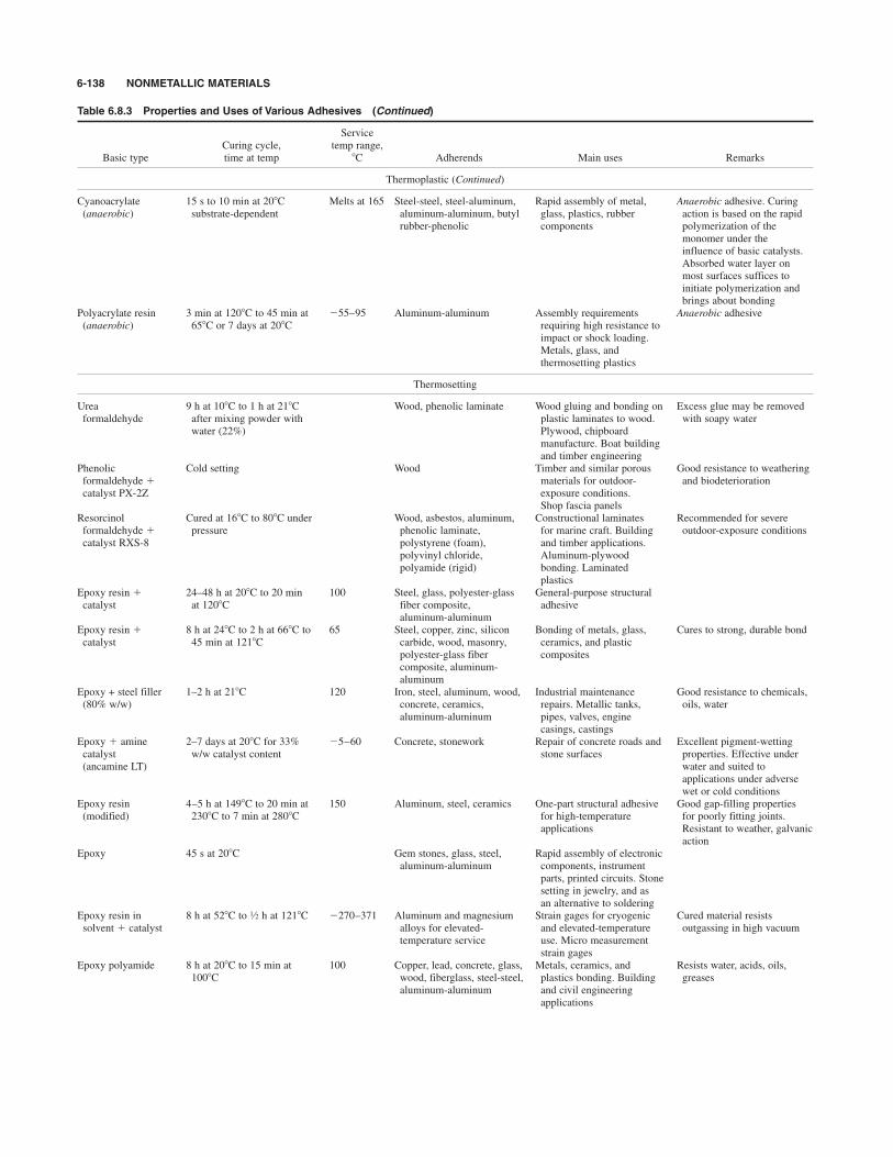
6-138 NONMETALLIC MATERIALS
Table 6.8.3 Properties and Uses of Various Adhesives (Continued)
ServiceCuring cycle, temp range,
Basic type time at temp *C Adherends Main uses Remarks
Thermoplastic (Continued)
Cyanoacrylate 15 s to 10 min at 20*C Melts at 165 Steel-steel, steel-aluminum, Rapid assembly of metal, Anaerobic adhesive. Curing (anaerobic) substrate-dependent aluminum-aluminum, butyl glass, plastics, rubber action is based on the rapid
rubber-phenolic components polymerization of themonomer under the influence of basic catalysts.Absorbed water layer onmost surfaces suffices toinitiate polymerization andbrings about bonding
Polyacrylate resin 3 min at 120*C to 45 min at $55–95 Aluminum-aluminum Assembly requirements Anaerobic adhesive(anaerobic) 658C or 7 days at 208C requiring high resistance to
impact or shock loading.Metals, glass, andthermosetting plastics
Thermosetting
Urea 9 h at 10*C to 1 h at 21*C Wood, phenolic laminate Wood gluing and bonding on Excess glue may be removed formaldehyde after mixing powder with plastic laminates to wood. with soapy water
water (22%) Plywood, chipboard manufacture. Boat buildingand timber engineering
Phenolic Cold setting Wood Timber and similar porous Good resistance to weathering formaldehyde & materials for outdoor- and biodeteriorationcatalyst PX-2Z exposure conditions.
Shop fascia panelsResorcinol Cured at 16*C to 80*C under Wood, asbestos, aluminum, Constructional laminates Recommended for severe formaldehyde & pressure phenolic laminate, for marine craft. Building outdoor-exposure conditionscatalyst RXS-8 polystyrene (foam), and timber applications.
polyvinyl chloride, Aluminum-plywoodpolyamide (rigid) bonding. Laminated
plasticsEpoxy resin & 24–48 h at 20*C to 20 min 100 Steel, glass, polyester-glass General-purpose structuralcatalyst at 120*C fiber composite, adhesive
aluminum-aluminumEpoxy resin & 8 h at 24*C to 2 h at 66*C to 65 Steel, copper, zinc, silicon Bonding of metals, glass, Cures to strong, durable bondcatalyst 45 min at 121*C carbide, wood, masonry, ceramics, and plastic
polyester-glass fiber compositescomposite, aluminum-aluminum
Epoxy + steel filler 1–2 h at 21*C 120 Iron, steel, aluminum, wood, Industrial maintenance Good resistance to chemicals, (80% w/w) concrete, ceramics, repairs. Metallic tanks, oils, water
aluminum-aluminum pipes, valves, enginecasings, castings
Epoxy & amine 2–7 days at 20*C for 33% $5–60 Concrete, stonework Repair of concrete roads and Excellent pigment-wettingcatalyst w/w catalyst content stone surfaces properties. Effective under(ancamine LT) water and suited to
applications under adversewet or cold conditions
Epoxy resin 4–5 h at 149*C to 20 min at 150 Aluminum, steel, ceramics One-part structural adhesive Good gap-filling properties (modified) 230*C to 7 min at 280*C for high-temperature for poorly fitting joints.
applications Resistant to weather, galvanic action
Epoxy 45 s at 20*C Gem stones, glass, steel, Rapid assembly of electronicaluminum-aluminum components, instrument
parts, printed circuits. Stonesetting in jewelry, and asan alternative to soldering
Epoxy resin in 8 h at 52*C to h at 121*C $270–371 Aluminum and magnesium Strain gages for cryogenic Cured material resistssolvent & catalyst alloys for elevated- and elevated-temperature outgassing in high vacuum
temperature service use. Micro measurementstrain gages
Epoxy polyamide 8 h at 20*C to 15 min at 100 Copper, lead, concrete, glass, Metals, ceramics, and Resists water, acids, oils,100*C wood, fiberglass, steel-steel, plastics bonding. Building greases
aluminum-aluminum and civil engineering applications
1⁄2
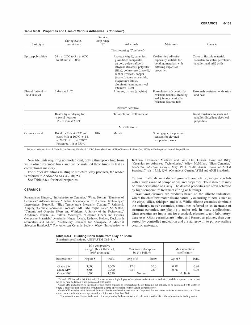
CERAMICS 6-139
New tile units requiring no mortar joint, only a thin epoxy line, formwalls which resemble brick and can be installed three times as fast asconventional masonry.For further definitions relating to structural clay products, the reader
is referred to ANSI/ASTM C43–70(75).See Table 6.8.4 for brick properties.
CERAMICS
REFERENCES: Kingery, “Introduction to Ceramics,” Wiley. Norton, “Elements ofCeramics,” Addison-Wesley. “Carbon Encyclopedia of Chemical Technology,”Interscience. Humenik, “High-Temperature Inorganic Coatings,” Reinhold.Kingery, “Ceramic Fabrication Processes,” MIT. McCreight, Rauch, Sr., Sutton,“Ceramic and Graphite Fibers and Whiskers; A Survey of the Technology,”Academic. Rauch, Sr., Sutton, McCreight, “Ceramic Fibers and FibrousComposite Materials,” Academic. Hague, Lynch, Rudnick, Holden, Duckworth(compilers and editors), “Refractory Ceramics for Aerospace; A MaterialSelection Handbook,” The American Ceramic Society. Waye, “Introduction to
Technical Ceramics,” Maclaren and Sons, Ltd., London. Hove and Riley,“Ceramics for Advanced Technologies,” Wiley. McMillan, “Glass-Ceramics,”Academic. Machine Design, May 1983. “1986 Annual Book of ASTMStandards,” vols. 15.02, 15.04 (Ceramics). Current ASTM and ANSI Standards.
Ceramic materials are a diverse group of nonmetallic, inorganic solidswith a wide range of compositions and properties. Their structure maybe either crystalline or glassy. The desired properties are often achievedby high-temperature treatment (firing or burning).Traditional ceramics are products based on the silicate industries,
where the chief raw materials are naturally occurring minerals such asthe clays, silica, feldspar, and talc. While silicate ceramics dominatethe industry, newer ceramics, sometimes referred to as electronic ortechnical ceramics, are playing a major role in many applications.Glass ceramics are important for electrical, electronic, and laboratory-ware uses. Glass ceramics are melted and formed as glasses, then con-verted, by controlled nucleation and crystal growth, to polycrystallineceramic materials.
Table 6.8.3 Properties and Uses of Various Adhesives (Continued)
ServiceCuring cycle, temp range,
Basic type time at temp *C Adherends Main uses Remarks
Thermosetting (Continued)
Epoxy/polysulfide 24 h at 20*C to 3 h at 60*C Asbestos (rigid), ceramics, Cold-setting adhesive Cures to flexible material. to 20 min at 100*C glass-fiber composites, especially suitable for Resistant to water, petroleum,
carbon, polytetrafluoro- bonding materials with alkalies, and mild acidsethylene (treated), polyester differing expansion (film), polystyrene (treated), propertiesrubber (treated), copper(treated), tungsten carbide, magnesium alloys, aluminum-aluminum, steel(stainless)-steel
Phenol furfural & 2 days at 21*C Alumina, carbon (graphite) Formulation of chemically Extremely resistant to abrasionacid catalyst resistant cements. Bedding and heat
and joining chemicallyresistant ceramic tiles
Pressure-sensitive
Heated by air drying for Teflon-Teflon, Teflon-metal Good resistance to acids and several hours or alkalies. Excellent electrical15–30 min at 210*F properties
Miscellaneous
Ceramic-based Dried for h at 77*C and 816 Metals Strain gages, temperature cured h at 100*C & 1 h sensors for elevated-at 200*C & 1 h at 250*C. temperature workPostcured, 1 h at 350*C
SOURCE: Adapted from J. Shields, “Adhesives Handbook,” CRC Press (Division of The Chemical Rubber Co., 1970), with the permission of the publisher.
1⁄2
1⁄2
Table 6.8.4 Building Brick Made from Clay or Shale(Standard specifications, ANSI/ASTM C62–81)
Min compressivestrength (brick flatwise), Max water absorption Max saturation
lb/in2 gross area by 5-h boil, % coefficient†
Designation* Avg of 5 Indiv. Avg of 5 Indiv. Avg of 5 Indiv.
Grade SW 3,000 2,500 17.0 20.0 0.78 0.80Grade MW 2,500 2,200 22.0 25.0 0.88 0.90Grade NW 1,500 1,250 No limit No limit
* Grade SW includes brick intended for use where a high degree of resistance to frost action is desired and the exposure is such thatthe brick may be frozen when permeated with water.Grade MW includes brick intended for use where exposed to temperatures below freezing but unlikely to be permeated with water or
where a moderate and somewhat nonuniform degree of resistance to frost action is permissible.Grade NW includes brick intended for use as backup or interior masonry, or if exposed, for use where no frost action occurs; or if frost
action occurs, where the average annual precipitation is less than 20 in.† The saturation coefficient is the ratio of absorption by 24 h submersion in cold water to that after 5 h submersion in boiling water.
Manufacture Typically, the manufacture of traditional-ceramicproducts involves blending of the finely divided starting materials withwater to form a plastic mass which can be formed into the desiredshape. The plasticity of clay constituents in water leads to excellentforming properties. Formation processes include extrusion, pressing,and ramming. Unsymmetrical articles can be formed by “slip-casting”techniques, where much of the water is taken up by a porous mold.After the water content of formed articles has been reduced by drying,the ware is fired at high temperature for fusion and/or reaction of thecomponents and for attainment of the desired properties. Firing tem-peratures can usually be considerably below the fusion point of the purecomponents through the use of a flux, often the mineral feldspar.Following burning, a vitreous ceramic coating, or glaze, may be appliedto render the surface smooth and impermeable.Quite different is the fusion casting of some refractories and refrac-
tory blocks and most glasses, where formation of the shaped article iscarried out after fusion of the starting materials.
Properties The physical properties of ceramic materials are stronglydependent on composition, microstructure (phases present and their dis-tribution), and the history of manufacture. Volume pore concentrationcan vary widely (0 to 30 percent) and can influence shock resistance,strength, and permeability. Most traditional ceramics have a glassy phase,a crystalline phase, and some porosity. The last can be eliminated at thesurface by glazing. Most ceramic materials are resistant to large com-pressive stresses but fail readily in tension. Resistance to abrasion, heat,and stains, chemical stability, rigidity, good weatherability, and brittle-ness characterize many common ceramic materials.
Products Many traditional-ceramic products are referred to aswhiteware and include pottery, semivitreous wares, electrical porcelains,sanitary ware, and dental porcelains. Building products which areceramic include brick and structural tile and conduit, while refractoryblocks, as well as many abrasives, are also ceramic in nature. Porcelainenamels for metals are opacified, complex glasses which are designed tomatch the thermal-expansion properties of the substrate. Importanttechnical ceramics include magnetic ceramics, with magnetic propertiesbut relatively high electrical resistance; nuclear ceramics, including ura-nium dioxide fuel elements; barium titanate as a material with very highdielectric constant. Several of the pure oxide ceramics with superiorphysical properties are being used in electrical and missile applicationswhere high melting and deformation temperatures and stability inoxygen are important. Fibrous ceramic composed of ziconium oxidefibers, such as Zircar, provide optimum combination of strength, lowthermal conductivity, and high temperature resistance to about 2,490*C(4,500*F). Partially stabilized zirconia, because of its steel-strong andcrack-resisting properties, is finding high-temperature applications, forexample, in diesel engines.Various forms of ceramics are available from manufacturers such as
paper, “board,” blankets, tapes, and gaskets.A fair amount of development is under way dealing with reinforcing
ceramics to yield ceramic matrix composite materials. The driving inter-est here is potential applications in high-temperature, high-stress envi-ronments, such as those encountered in aircraft and aerospace structuralcomponents. None of the end products are available yet “off the shelf,”and applications are likely to be quite circumscribed and relegated tosolution of very specialized design problems.Ceramic inserts suitably shaped and mechanically clamped in tool hold-
ers are applied as cutting tools, and they find favor especially for cuttingabrasive materials of the type encountered in sand castings or forgingswith abrasive oxide crusts. They offer the advantage of resisting abrasionat high tool/chip interface temperatures, and consequently they exhibitrelatively long tool life between sharpenings. They tend to be somewhatbrittle and see limited service in operations requiring interrupted cuts;when they are so applied, tool life between sharpenings is very short.
CLEANSING MATERIALS
REFERENCES: McCutcheon, “Detergents and Emulsifiers,” McCutcheon, Inc.Schwartz, Perry, and Berch, “Surface Active Agents and Detergents,”Interscience. ASTM Special Tech. Pub. 197. Niven, “Industrial Detergency,”
Reinhold. McLaughlin, “The Cleaning, Hygiene, and Maintenance Handbook,”Prentice-Hall. Hackett, “Maintenance Chemical Specialties,” ChemicalPublishing Co. Bennett (ed.), “Cold Cleaning with Halogenated Solvents,” ASTMSpecial Technical Publication 403, 1966. ANSI/ASTM D459, D534–1979 (defi-nitions and specifications).
Cleansing is the removal of dirt, soil, and impurities from surfaces of allkinds. Means of soil attachment to the surface include simple entrap-ment in interstices, electrostatically held dirt, wetting of the surfacewith liquid soils, and soil-surface chemical reaction. A variety ofcleansing systems has been developed which are difficult to classifysince several soil-removal mechanisms are often involved. A liquid sus-pending medium, an active cleansing agent, and mechanical action areusually combined. The last may involve mechanical scrubbing, bathagitation, spray impingement, or ultrasonic energy. Cleansing involvesdetachment from the surface, suspension of solids or emulsification ofliquids, or dissolution, either physical or by chemical reaction.
Organic Solvents
Both petroleum solvents (mineral spirits or naphtha) and chlorinatedhydrocarbons (trichloroethylene and perchloroethylene) are used toremove solvent-soluble oils, fats, waxes, and greases as well as to flushaway insoluble particles. Petroleum solvents are used in both soak-tankand spray equipment. Chlorinated hydrocarbons are widely used invapor degreasing (where the metal stock or part is bathed in the con-densing vapor), their high vapor density and nonflammability beingadvantageous. Solvent recovery by distillation can be used if the oper-ation is of sufficient size. Both solvent types are used in garment drycleaning with solvent-soluble detergents.Fluorocarbons such as UCON solvent 113-LRI (trichlorotrifluo-
roethane) are nonflammable and are ideal for critical cleaning ofmechanical electrical and electronic equipment, especially for white-room conditions.Fluorocarbon solvents are highly proscribed and regulated and are to
be used only with utmost care, under close supervision and accountablecontrol. The reader should become familiar with the several referencespertaining to health hazards of industrial materials listed underChlorinated Solvents in this section.Emulsifiable solvent cleaners contain a penetrating solvent and dis-
solved emulsifying agent. Following soaking, the surface is flushedwith hot water, the resulting emulsion carrying away both soil and sol-vent. These cleaners are usually extended with kerosinelike solvents.
Alkali Cleansers
Alkali cleansers are water-soluble inorganic compounds, often strongcleansers. Carbonates, phosphates, pyrophosphates, and caustic sodaare common, with numerous applications in plant maintenance, mater-ial processing, and process-water treatment. Cleansing mechanismsvary from beneficial water softening and suspension of solids to chem-ical reaction in the solubilization of fats and oils. Certain of these com-pounds are combined with detergents to improve efficiency; these arereferred to as builders. Boiler and process equipment scales can some-times be controlled or removed with selected alkali cleansers.
Synthetic Detergents
Detergents concentrate strongly at a solid-liquid or liquid-liquid inter-face and are thus characterized as surface active. In contrast to soaps,they can be tailored to perform over a wide range of conditions of tem-perature, acidity, and presence of dissolved impurities with little or nofoaming. Detergents promote wetting of the surface by the suspendingmedium (usually water), emulsification of oils and greases, andsuspension of solids without redeposition, the last function being theprime criterion of a good detergent. Detergents are classified as anionic(negatively charged in solution), cationic (positively charged), andnonionic. Germicidal properties may influence detergent choice.For specific applications, the supplier should be consulted since there
is a large variety of available formulations and since many detergentsystems contain auxiliary compounds which may be diluents, foam pro-motors, or alkali chemicals. Additives are designed for pH control,
6-140 NONMETALLIC MATERIALS

ELECTRICAL INSULATING MATERIALS 6-141
water softening, and enhanced suspending power. Formulations havebeen developed for cleaning food and dairy process equipment, metalsprocessing, metal cleaning prior to electroplating, textile fiber and fab-ric processing, and industrial building maintenance. Strong, improperlyselected detergent systems can cause deterioration of masonry or mar-ble floors, aluminum window frames, water-based paints, and floortiles, whereas detergents matched to the job at hand can result inincreased plant efficiency.Soaps, the oldest surface-active cleansers, lack the versatility of syn-
thetic detergents but are widely used in the home and in the laundryindustry. Properties depend on the fat or oil and alkali used in theirpreparation and include solvent-soluble soaps for dry cleaning.Chemical cleaners which attack specific soils include dilute acid for
metal oxide removal, for the cleaning of soldered or brazed joints, andfor the removal of carbonate scale in process equipment. Oxalic acid(usually with a detergent) is effective on rust.Chelating agents are organic compounds which complex with several
metal ions and can aid in removal of common boiler scales and metaloxides from metal surfaces.Steam cleaning in conjunction with a detergent is effective on grease-
laden machinery.There are numerous cleansers for the hands, including Boraxo, soap
jelly and sawdust, lard for loosening oil grime, and linseed oil forpaints; repeated use of solvents can be hazardous.Alcohol ethoxylates are nonionic surfactants suitable for use in the pro-
duction of maintenance and institutional cleaners. Products such asTergitol and Neodol 23–6.5 serve in the formulation of liquid detergentsfor household and industrial uses.Alcohol ethoxysulfates are anionic surfactants which are suited to the
formulation of high-foaming liquid detergents, as for manual dishwash-ing. They offer the advantages of excellent solubility and biodegradabil-ity. Neodol 25–3S40 also exhibits low sensitivity to water hardness.Enzyme cleaners containing a combination of bacteria culture,
enzymes, and nutrients are used to dissolve grease, human waste, andprotein stains.
CORDAGE
REFERENCE: Himmelfarb, “The Technology of Cordage Fibers and Rope,” TextileBook Publishers, Inc. (division of Interscience Publishers, Inc.).
The term cordage denotes any flexible string or line. Usage includes wrap-ping, baling, hauling, and power transmission in portable equipment.Twine and cord generally imply lines of in diam or less, with largersizes referred to as rope.
3⁄8
Natural fibers used in cordage are abaca, sisal, hemp, cotton, andjute. For heavy cordage abaca and manila predominate. Hemp is usedfor small, tarred lines, and henequen for agricultural binder twine.Rope is made by twisting yarns into strands, with the strands (usually
three) twisted (laid) into a line. The line twist may be S or Z (see Sec.10), generally opposite to the twist of the strands, which, in turn, isopposite to the twist of the yarns. The term lay designates the numberof turns of the strands per unit length of rope but may also characterizethe rope properties, a function of the degree of twist of each component.Grades range from soft lay (high ultimate strength) to hard lay (highabrasion resistance). Cable-laid rope results from twisting together con-ventional, three-strand rope.Synthetic fibers are used in cordage because of resistance to rot, high
strength, and other special properties. These fibers include nylon forstrength, polyester (Dacron) for strength and dimensional stability, vinyls for chemical-plant use, fiberglass for electrical stability, vinylsfor chemical-plant use, fiberglass for electrical and chemical properties,and polypropylene for strength and flotation (see Sec. 8). Braided cordage has been used largely for small diameter lines such
as sash cord and clothesline. However, braided lines are now availablein larger diameters between 2 and 3 in. The strength of braided rope isslightly superior, and the line has less tendency to elongate in tensionand cannot rotate or unlay under load. These properties are balancedagainst a somewhat higher cost than that of twisted rope.A no. 1 common-lay rope will conform to the strength and weight
table of the Federal Specification TR601A listed below.For comparison, a nylon rope of a given diameter will have about 3
times the breaking strength given above and a polyester rope about 2times the strength of manila. Both have substantially greater flex andabrasion resistance.See Table 6.8.5 for manila rope properties.
ELECTRICAL INSULATING MATERIALS
REFERENCES: Plastics Compositions for Dielectrics, Ind. Eng. Chem., 38, 1946,p. 1090. High Dielectric Ceramics, Ind. Eng. Chem., 38, 1946, p. 1097. PolystyrenePlastics as High Frequency Dielectrics, Ind. Eng. Chem., 38, 1946, p. 1121.Paper Capacitors Containing Chlorinated Impregnants, Ind. Eng. Chem., 38, 1946,p. 1110. “Contributions of the Chemist to Dielectrics,” National Research Council,1947. National Research Council, Conference on Electrical Insulation, (1) AnnualReport, (2) Annual Digest of Literature on Dielectrics. Von Hippel, “Di-electricMaterials and Applications,” Wiley. Birks (ed.), “Modern Dielectric Materials,”Academic. Saums and Pendelton, “Materials for Electrical Insulating andDielectric Functions,” Hayden Book, Inc. Licari, “Plastic Coatings forElectronics,” McGraw-Hill. Clark, “Insulating Materials for Design andEngineering Practice,” Wiley. Mayofis, “Plastic Insulating Materials,” Illiffe, Ltd.,
1⁄2
Table 6.8.5 Weight and Strength of Different Sizes of Manila Rope Specification Values
0.015 450 0.195 6,500 0.895 26,5000.020 600 2.225 7,700 2 6 1.08 31,000
1 0.029 1,000 1 3 0.270 9,000 7 1.46 41,0000.041 1,350 0.313 10,500 8 1.91 52,0000.053 1,750 0.360 12,000 3 9 2.42 64,0000,075 2,650 0.418 13,500 10 2.99 77,0000.104 3,450 4 0.480 15,000 11 3.67 91,000
2 0.133 4,400 0.600 18,500 4 12 4.36 105,0000.167 5,400 5 0.744 22,500
The approximate length of coil is 1,200 ft for diam in and larger. For smaller sizes it is longer, up to 3,000 ft for in diam.* 1 in # 0.0254 m; 1 ft # 0.3048 m.† 1 lbf # 4.448 N.SOURCE: U.S. government specification TR601A, dated Nov. 26, 1935, formulated jointly by cordage manufacturers and government representatives.
3⁄167⁄16
15⁄821⁄43⁄441⁄211⁄211⁄16
35⁄815⁄1613⁄49⁄1631⁄433⁄411⁄411⁄21⁄2
31⁄213⁄1611⁄47⁄1625⁄831⁄411⁄1611⁄83⁄821⁄45⁄16
23⁄415⁄163⁄41⁄451⁄2113⁄1621⁄213⁄165⁄83⁄16
Min breaking
strength, lb
Max net weight,
lb/ft
Circumference,
inApprox diam,
inMin breaking
strength, lb
Max net weight,
lb/ft
Circumference,
in*
Approx diam,
in*
Min breaking
strength, lb†
Max net weight,
lb/ft
Circumference,
in*
Approx diam,
in*
London. Bruins (ed.), “Plastic for Electrical Insulation,” Interscience Publishers.Swiss Electrochemical Committee, “Encyclopedia of Electrical InsulatingMaterials,” Bulletin of the Swiss Association of Electrical Engineers, vol. 48,1958. ISO 455–3–1 1981. “1986 Annual Book of ASTM Standards,” vols.10.01–10.03 (Electrical Insulating Materials). Current ASTM and ANSIStandards.
The insulating properties of any material are dependent upon dielectricstrength, or the ability to withstand high voltages without breakdown;ohmic resistance, or the ability to prevent leakage of small currents;and power loss, or the absorption of electrical energy that is trans-formed into heat. Power loss depends upon a number of influences, par-ticularly the molecular symmetry of the insulation and frequency of thevoltage, and is the basis of power factor, an important considerationwhenever efficient handling of alternating currents is concerned, and adominating consideration when high frequencies are used, as in radiocircuits. Materials may have one of these qualities to a far greater extentthan the other; e.g., air has a very high specific resistance but very littledielectric strength and no power loss at any frequency; glass has greatdielectric strength yet much lower resistance than air. The ideal insula-tor is one having the maximum dielectric strength and resistance, min-imum power loss, and also mechanical strength and chemical stability.Moisture is by far the greatest enemy of insulation; consequently theabsence of hygroscopic quality is desirable.The common insulating materials are described below. For their elec-
trical properties, see Sec. 15.Rubber See Rubber and Rubberlike Materials.Mica and Mica Compounds Mica is a natural mineral varying
widely in color and composition, and occurs in sheets that can be sub-divided down to a thickness of 0.00025 in. White mica is best for elec-trical purposes. The green shades are the softest varieties, and the whiteamber from Canada is the most flexible. Mica has high insulating qual-ities, the best grades having a dielectric strength of 12,000 V per 0.1 mm.Its lack of flexibility, its nonuniformity, and its surface leakage are dis-advantages. To offset these, several mica products have been developed,in which small pieces of mica are built up into finished shapes by meansof binders such as shellac, gum, and phenolic resins.Micanite consists of thin sheets of mica built into finished forms with
insulating cement. It can be bent when hot and machined when cold, andis obtainable in thicknesses of 0.01 to 0.12 in. Flexible micanite plates,cloth, and paper are also obtainable in various thicknesses. Megohmit issimilar to micanite except that it is claimed not to contain adhesive mat-ter. It can be obtained in plates, paper, linen, and finished shapes.Megotalc, built up from mica and shellac, is similar to the above-namedproducts and is obtainable in similar forms.
Insulating Varnishes Two general types of insulating varnish areused: (1) asphalt, bitumen, or wax, in petroleum solvent, and (2) drying-oil varnishes based on natural oils compounded with resins from nat-ural or synthetic sources. Varnishes have changed greatly in the lastfew years, since new oils have become available, and particularly sincephenolic and alkyd resins have been employed in their manufacture.Silicone varnishes harden by baking and have electrical properties
similar to those of the phenol-aldehyde resins. They are stable at tem-peratures up to 300*F (138*C). They can be used as wire coatings, andsuch wire is used in the manufacture of motors that can operate at hightemperatures.
Impregnating Compounds Bitumens and waxes are used toimpregnate motor and transformer coils, the melted mix being forcedinto the coil in a vacuum tank, forming a solid insulation when cooled.Brittle compounds, which gradually pulverize owing to vibration in ser-vice, and soft compounds, which melt and run out under service tem-peratures, should be avoided as far as possible.
Oil Refined grades of petroleum oils are extensively used for theinsulation of transformers, switches, and lightning arresters. The fol-lowing specification covers the essential points:Specific gravity, 0.860; flash test, not less than 335*F; cold test,
not more than $10*C (14*F); viscosity (Saybolt) at 37.8*C (100*F),not more than 120 s; loss on evaporation (8 h at 200*F), not morethan 0.5 percent; dielectric strength, not less than 35,000 V; freedom
from water, acids, alkalies, saponifiable matter, mineral matter or freesulfur. Moisture is particularly dangerous in oil.Petroleum oils are used for the impregnation of kraft or manila paper,
after wrapping on copper conductors, to form high-voltage power cablesfor services up to 300,000 V. Oil-impregnated paper insulation is sen-sitive to moisture, and such cables must be lead-sheathed. The trans-mission of power at high voltages in underground systems is universallyaccomplished by such cables.
Chlorinated Hydrocarbons Chlorinated hydrocarbons have theadvantage of being nonflammable and are used as filling compoundsfor transformers and condensers where this property is important.Chlorinated naphthalene and chlorinated diphenyl are typical of thisclass of material. They vary from viscous oils to solids, with a widerange of melting points. The reader is cautioned to investigate the use ofsuch insulation carefully because of alleged carcinogenic propensities.
Impregnated Fabrics Fabrics serve as a framework to hold a film ofinsulating material and must therefore be of proper thickness, texture,and mechanical strength, and free from nap and acidity. A wide varietyof drying varnishes is used for the impregnation, and the dipping isfollowed by baking in high-temperature towers. Varnished cambric isused for the wrapping of coils and for the insulation of conductors.These cables have high power factor and must be kept free of moisture,but they are desirable for resisting electrical surges.Thermosetting substances of the phenol-aldehyde type and of the
ureaformaldehyde type first soften and then undergo a chemical reac-tion which converts them quickly to a strong infusible product. Goodproperties are available in the phenolics, while numerous special typeshave been developed for high heat resistance, low-power-factor arcresistance, and other specialized properties. A wide variety of resins isavailable. The urea plastics are lacking in heat resistance but are suit-able for general-purpose molding and have fair arc resistance.Thermoplastic resins (see Plastics, below) are used for molding and
extruding electrical insulations. They differ from the thermosettingresins in that they do not become infusible. Polyethylene softensbetween 99 and 116*C (210 and 240*F). Its dielectric strength and resis-tivity are high, its power factor is only 0.0003, and its dielectric constantis 2.28. It is used extensively in high-frequency and radar applicationsand as insulation on some power and communication cables. Teflon is afluorocarbon resin which has electrical properties similar to those ofpolyethylene. Its softening point is 750*F approx, and it extrudes andmolds with difficulty; however, more tractable grades of Teflon are nowavailable. It is resistant to nearly all chemicals and solvents.Nylon is a synthetic plastic with interesting mechanical and electri-
cal properties. It has only fair water resistance. Its melting point is 198to 249*C (390 to 480*F), and is used for the molding of coil forms. Itcan be extruded onto wire in thin layers. Such wires are used in placeof the conventional varnish-coated magnet wires in coils and motors.Operation may be at temperatures up to 127*C (260*F).
Paper Except in lead-sheathed telephone cables, the present ten-dency is to use paper only as a backing or framework for an insulatingfilm or compound, owing to its hygroscopic qualities. Manila and kraftpapers possess the best dielectric and mechanical strength and, whencoated with good insulating varnish, are excellent insulators. Varioustypes of paraffined paper are used in condensers. (See also Paper, below.)Silicone rubber (see Silicones) is a rubberlike material of good
physical properties [tensile strength, 400 to 700 lb/in2 (2.78 to 4.85 %106 N/m2) elongation, 200 percent]. It can be operated for long periodsof time at temperatures up to 138*C (300*F) or intermittently up to249*C (480*F).Ceramics and glasses find wide usage as insulating materials where
brittleness and lack of flexibility can be tolerated.Polymeric (plastic) films, particularly the polyester and fluorocarbon
types, are being used increasingly where fabrication of the electricalcomponent permits either wrapping or insertion of film chips.Heat-shrinkable tubing of polyvinylchloride, polyolefin, or polytetra-
fluoroethylene compositions allow for very tight-fitting insulationaround a member, thus affording efficient protection of electrical wiresor cables.
6-142 NONMETALLIC MATERIALS

FIBERS AND FABRICS 6-143
FIBERS AND FABRICS
(See also Cordage.)
REFERENCES: Matthews-Mauersberger, “The Textile Fibers,” Wiley. Von Bergenand Krauss, “Textile Fiber Atlas,” Textile Book Publishers, Inc. Hess, “TextileFibers and Their Use,” Lippincott. Sherman and Sherman, “The New Fibers,” VanNostrand. Kaswell, “Textile Fibers, Yarns and Fabrics,” Reinhold. “Harris’Handbookof Textile Fibers,” Waverly House. Kaswell, “Wellington Sears Handbook ofIndustrial Textiles,” Wellington Sears Co. Fiber Charts, Textile World,McGraw-Hill.ASTM Standards. C. Z. Carroll-Porcynski, “Advanced Materials; RefractoryFibers, Fibrous Metals, Composites,” Chemical Publishing Co. Marks, Atlas, andCernia, “Man-Made Fibers, Fibrous Metals, Composites,” Chemical PublishingCo. Marks, Atlas, and Cernia, “Man-Made Fibers, Science and Technology,”Interscience Publishers. Frazer, High Temperature Resistant Fibers, Jour. PolymerSci., Part C, Polymer Symposia, no. 19, 1966. Moncrieff, “Man-Made Fibers,”Wiley. Preston and Economy, “High Temperature and Flame Resistant Fibers,”Wiley. ANSI/ASTM Standards D1175-D 3940. ANSI/ AATCC Standards 79, 128.“1986–1994 Annual Book of ASTM Standards,” vols. 07.01, 07.02 (Textiles).Current ASTM and ANSI Standards.
Fibers are threadlike structural materials, adaptable for spinning,weaving, felting, and similar applications. They may be of natural orsynthetic origin and of inorganic or organic composition. Fabrics aredefined by the ASTM as “planar structures produced by interlacingyarns, fibers, or filaments.” A bonded fabric (or nonwoven fabric) con-sists of a web of fibers held together with a cementing medium whichdoes not form a continuous sheet of adhesive material. A braidedfabric is produced by interlacing several ends of yarns such that thepaths of the yarns are not parallel to the fabric axis. A knitted fabric isproduced by interlooping one or more ends of yarn. A woven fabric isproduced by interlacing two or more sets of yarns, fibers or filamentssuch that the elements pass each other essentially at right angles and oneset of elements is parallel to the fabric axis. A woven narrow fabric is12 in or less in width and has a selvage on either side.
Inorganic Fibers
Asbestos is the only mineral fiber of natural origin. Its demonstrated car-cinogenic properties, when its particles lodge in the lung, have led to itsremoval from most consumer products. Formerly ubiquitously appliedas a thermal insulator, it has now been proscribed from that use and hasbeen supplanted largely by fiberglass.Synthetic mineral fibers are spun glass, rock wool, and slag wool. These
fibers can endure high temperatures without substantial loss of strength.Glass fibers possess a higher strength-to-weight ratio at the elastic limitthan do other common engineering materials.Metal filaments (wires) are used as textile fibers where their particu-
lar material properties are important.Carbon (graphite) fibers, such as Thornel, are high-modulus, highly ori-
ented structures characterized by the presence of carbon crystallites(polycrystalline graphite) preferentially aligned parallel to the fiber axis.Depending on the particular grade, tensile strengths can range from10.3 to 241 % 107 N/m2 (15,000 to 350,000 lb/in2). Hybrid compositesof carbon and glass fibers find aerospace and industrial applications.Zirconia fibers (ZrO2 & HFO2 & stabilizers), such as Zircar, have
excellent temperature resistance to about 2,200*C (4,000*F), and fabricswoven from the fibers serve as thermal insulators.
Natural Organic Fibers
The animal fibers include wool from sheep, mohair from goats, camel’shair, and silk. Wool is the most important of these, and it may beprocessed to reduce its susceptibility to moth damage and shrinkage.Silk is no longer of particular economic importance, having been sup-planted by one or another of the synthetic fibers for most applications.The vegetable fibers of greatest utility consist mainly of cellulose and
may be classified as follows: seed hairs, such as cotton; bast fibers, suchas flax, hemp, jute, and ramie; and vascular fibers. Those containing themost cellulose are the most flexible and elastic and may be bleachedwhite most easily. Those which are more lignified tend to be stiff, brit-tle, and hard to bleach. Vegetable fibers are much less hygroscopic thanwool or silk.
Mercerized cotton is cotton fiber that has been treated with strongcaustic soda while under tension. The fiber becomes more lustrous,stronger, and more readily dyeable.
Synthetic Organic Fibers
In recent years, a large and increasing portion of commercial fiber pro-duction has been of synthetic or semisynthetic origin. These fibers pro-vide generally superior mechanical properties and greater resistance todegradation than do natural organic fibers and are available in a varietyof forms and compositions for particular end-use applications. Genericcategories of man-made fibers have been established by the TextileFiber Products Identification Act, 15 USC 70, 72 Stat. 1717.Among the important fibers are rayons, made from regenerated cellu-
lose, plain or acetylated, which has been put into a viscous solution andextruded through the holes of a spinneret into a setting bath. The typesmost common at present are viscose and acetate. Cuprammonium rayon,saponified acetate rayon, and high-wet-modulus rayon are also manufac-tured and have properties which make them suitable for particular appli-cations. Rayon is generally less expensive than other synthetic fibers.In contrast to these regenerated fibers are a variety of polymer fibers
which are chemically synthesized. The most important is nylon,including nylon 6.6, a condensation polymer of hexamethylenediamineadipic acid, and nylon 6, a polymer of caprolactam. Nylon pos-sesses outstanding mechanical properties and is widely used in indus-trial fabrics. Nomex, a high-temperature-resistant nylon retains itsmost important properties at continuous operating temperatures up to260*C (500*F). Other polymer fibers possess mechanical or chemicalproperties which make them a specific material of choice for special-ized applications. These include polyester fibers, made from polyethyl-ene terephthalate; acrylic and modacrylic fibers, made from copolymersof acrylonitrile and other chemicals; Saran, a polymer composedessentially of vinylidene chloride; and the olefins, including polyethyl-enes and polypropylene.Teflon, a fluorocarbon resin, has excellent chemical resistance to acids,
bases, or solvents. Its useful physical properties range from cryogenictemperatures to 260*C(500*F), high dielectric strength, low dissipationfactor, and high resistivity, along with the lowest coefficient of friction ofany solid. It is nonflammable and is inert to weather and sunlight.As part of their manufacture, substantially all synthetic fibers are
drawn (hot- or cold-stretched) after extrusion to achieve desirablechanges in properties. Generally, increases in draw increase breakingstrength and modulus and decrease ultimate elongation.
Proximate Identification of Fibers Fibers are most accurately dis-tinguished under the microscope, with the aid of chemical reagents andstains. A useful rough test is burning, in which the odor of burned meatdistinguishes animal fibers from vegetable and synthetic fibers. Animalfibers, cellulose acetate, and nylon melt before burning and fuse to hardrounded beads. Cellulose fibers burn off sharply. Cellulose acetate dis-solves in either acetone or chloroform containing some alcohol.
Heat Endurance Fibers of organic origin lose strength when heatedover long periods of time above certain temperatures: cellulose,149*C (300*F); cellulose acetate, 93.5*C (200*F); nylon, 224*C (435*F);casein, 100*C (212*F); and glass, 316*C (600*F).
Creep Textile fibers exhibit the phenomenon of creep at relativelylow loads. When a textile fiber is subjected to load, it suffers three kindsof distortion: (1) an elastic deformation, closely proportioned to loadand fully and instantly recoverable upon load removal; (2) a primarycreep, which increases at a decreasing rate with time and which is fully,but not instantaneously, recoverable upon load removal; and (3) a sec-ondary creep, which varies obscurely with time and load and is com-pletely nonrecoverable upon load removal. The relative amounts ofthese three components, acting to produce the total deformation, varywith the different fibers. The two inelastic components give rise tomechanical hysteresis on loading and unloading.
Felts and Fabrics
A felt is a compacted formation of randomly entangled fibers. Wool feltis cohesive because the scaly structure of the wool fibers promotes
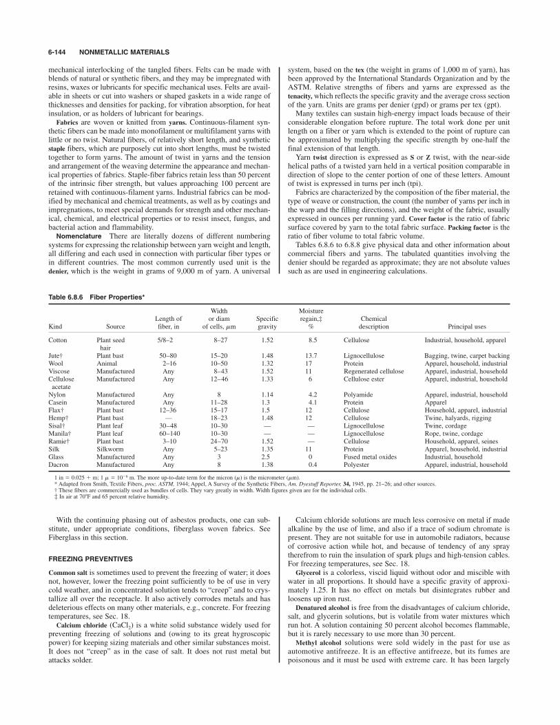
mechanical interlocking of the tangled fibers. Felts can be made withblends of natural or synthetic fibers, and they may be impregnated withresins, waxes or lubricants for specific mechanical uses. Felts are avail-able in sheets or cut into washers or shaped gaskets in a wide range ofthicknesses and densities for packing, for vibration absorption, for heatinsulation, or as holders of lubricant for bearings.Fabrics are woven or knitted from yarns. Continuous-filament syn-
thetic fibers can be made into monofilament or multifilament yarns withlittle or no twist. Natural fibers, of relatively short length, and syntheticstaple fibers, which are purposely cut into short lengths, must be twistedtogether to form yarns. The amount of twist in yarns and the tensionand arrangement of the weaving determine the appearance and mechan-ical properties of fabrics. Staple-fiber fabrics retain less than 50 percentof the intrinsic fiber strength, but values approaching 100 percent areretained with continuous-filament yarns. Industrial fabrics can be mod-ified by mechanical and chemical treatments, as well as by coatings andimpregnations, to meet special demands for strength and other mechan-ical, chemical, and electrical properties or to resist insect, fungus, andbacterial action and flammability.
Nomenclature There are literally dozens of different numberingsystems for expressing the relationship between yarn weight and length,all differing and each used in connection with particular fiber types orin different countries. The most common currently used unit is thedenier, which is the weight in grams of 9,000 m of yarn. A universal
system, based on the tex (the weight in grams of 1,000 m of yarn), hasbeen approved by the International Standards Organization and by theASTM. Relative strengths of fibers and yarns are expressed as thetenacity, which reflects the specific gravity and the average cross sectionof the yarn. Units are grams per denier (gpd) or grams per tex (gpt).Many textiles can sustain high-energy impact loads because of their
considerable elongation before rupture. The total work done per unitlength on a fiber or yarn which is extended to the point of rupture canbe approximated by multiplying the specific strength by one-half thefinal extension of that length.Yarn twist direction is expressed as S or Z twist, with the near-side
helical paths of a twisted yarn held in a vertical position comparable indirection of slope to the center portion of one of these letters. Amountof twist is expressed in turns per inch (tpi).Fabrics are characterized by the composition of the fiber material, the
type of weave or construction, the count (the number of yarns per inch inthe warp and the filling directions), and the weight of the fabric, usuallyexpressed in ounces per running yard. Cover factor is the ratio of fabricsurface covered by yarn to the total fabric surface. Packing factor is theratio of fiber volume to total fabric volume.Tables 6.8.6 to 6.8.8 give physical data and other information about
commercial fibers and yarns. The tabulated quantities involving thedenier should be regarded as approximate; they are not absolute valuessuch as are used in engineering calculations.
6-144 NONMETALLIC MATERIALS
Table 6.8.6 Fiber Properties*
Width MoistureLength of or diam Specific regain,‡ Chemical
Kind Source fiber, in of cells, mm gravity % description Principal uses
Cotton Plant seed 5/8–2 8–27 1.52 8.5 Cellulose Industrial, household, apparelhair
Jute† Plant bast 50–80 15–20 1.48 13.7 Lignocellulose Bagging, twine, carpet backingWool Animal 2–16 10–50 1.32 17 Protein Apparel, household, industrialViscose Manufactured Any 8–43 1.52 11 Regenerated cellulose Apparel, industrial, householdCellulose Manufactured Any 12–46 1.33 6 Cellulose ester Apparel, industrial, householdacetateNylon Manufactured Any 8 1.14 4.2 Polyamide Apparel, industrial, householdCasein Manufactured Any 11–28 1.3 4.1 Protein ApparelFlax† Plant bast 12–36 15–17 1.5 12 Cellulose Household, apparel, industrialHemp† Plant bast — 18–23 1.48 12 Cellulose Twine, halyards, riggingSisal† Plant leaf 30–48 10–30 — — Lignocellulose Twine, cordageManila† Plant leaf 60–140 10–30 — — Lignocellulose Rope, twine, cordageRamie† Plant bast 3–10 24–70 1.52 — Cellulose Household, apparel, seinesSilk Silkworm Any 5–23 1.35 11 Protein Apparel, household, industrialGlass Manufactured Any 3 2.5 0 Fused metal oxides Industrial, householdDacron Manufactured Any 8 1.38 0.4 Polyester Apparel, industrial, household
1 in # 0.025 & m; 1 m # 10$6 m. The more up-to-date term for the micron (m) is the micrometer (mm).* Adapted from Smith, Textile Fibers, proc. ASTM, 1944; Appel, A Survey of the Synthetic Fibers, Am. Dyestuff Reporter, 34, 1945, pp. 21–26; and other sources.† These fibers are commercially used as bundles of cells. They vary greatly in width. Width figures given are for the individual cells.‡ In air at 70*F and 65 percent relative humidity.
With the continuing phasing out of asbestos products, one can sub-stitute, under appropriate conditions, fiberglass woven fabrics. SeeFiberglass in this section.
FREEZING PREVENTIVES
Common salt is sometimes used to prevent the freezing of water; it doesnot, however, lower the freezing point sufficiently to be of use in verycold weather, and in concentrated solution tends to “creep” and to crys-tallize all over the receptacle. It also actively corrodes metals and hasdeleterious effects on many other materials, e.g., concrete. For freezingtemperatures, see Sec. 18.Calcium chloride (CaCl2) is a white solid substance widely used for
preventing freezing of solutions and (owing to its great hygroscopicpower) for keeping sizing materials and other similar substances moist.It does not “creep” as in the case of salt. It does not rust metal butattacks solder.
Calcium chloride solutions are much less corrosive on metal if madealkaline by the use of lime, and also if a trace of sodium chromate ispresent. They are not suitable for use in automobile radiators, becauseof corrosive action while hot, and because of tendency of any spraytherefrom to ruin the insulation of spark plugs and high-tension cables.For freezing temperatures, see Sec. 18.Glycerol is a colorless, viscid liquid without odor and miscible with
water in all proportions. It should have a specific gravity of approxi-mately 1.25. It has no effect on metals but disintegrates rubber andloosens up iron rust.Denatured alcohol is free from the disadvantages of calcium chloride,
salt, and glycerin solutions, but is volatile from water mixtures whichrun hot. A solution containing 50 percent alcohol becomes flammable,but it is rarely necessary to use more than 30 percent. Methyl alcohol solutions were sold widely in the past for use as
automotive antifreeze. It is an effective antifreeze, but its fumes arepoisonous and it must be used with extreme care. It has been largely

GLASS 6-145
supplanted for this use by ethylene glycol solutions, which are appliedin automotive practice and for stationary applications where, e.g., it iscirculated in subgrade embedded pipes and thus inhibits formation ofice on walking surfaces.Ethylene glycol (Prestone) is used as a freezing preventive and also
permits the use of high jacket temperatures in aircraft and other engines.Sp gr 1.125 (1.098) at 32 (77)*F; boiling point, 387*F; specific heat,0.575 (0.675) at 68 (212)*F. It mixes with water in all proportions.See Table 6.8.9 for nonfreezing percentages by volume.Winter-summer concentrates, such as Prestone 11, an ethylene glycol
base combined with patented inhibitor ingredients, give maximumfreezing protection to about $92*F ($62*C) at 68 percent mixture, andto about $34*F ($37*C) at 50 percent mixture.Anti-icing of fuels for aircraft is accomplished by adding ethylene
glycol monomethyl ether mixtures as Prist.
GLASS
REFERENCES: Journal of American Ceramic Society, Columbus, Ohio. Journalof the Society of Glass Technology, Sheffield, England. Morey, “Properties ofGlass,” Reinhold. Scholes, “Handbook of the Glass Industry,” Ogden-Watney.“Non-Silica Glasses,” Chem. & Met. Eng., Mar. 1946. Phillips, “Glass the
Miracle-Maker,” Pitman. Long, “Propriétés physiques et fusion du verre,” Dunod.Eitel-Pirani-Scheel, “Glastechnische Tabellen,” Springer. Jebsen-Marwedel,“Glastechnische Fabrikationsfehler,” Springer. Shand, “Glass EngineeringHandbook,” McGraw-Hill. Phillips, “Glass: Its Industrial Applications,”Reinhold. Persson, “Flat Glass Technology,” Plenum Press, 1969. McMillan,“Glass-Ceramics,” Academic. Pye, Stevens, and La Course (eds.), “Introductionto Glass Science,” Plenum Press. Jones, “Glass,” Chapman & Hall. Doremus,“Glass Science,” Wiley. Technical Staffs Division, “Glass,” Corning Glass Works.ANSI/ASTM C “1986 Annual Book of ASTM Standards,” vol. 15.02 (Glass).Current ASTM and ANSI Standards.
Glass is an inorganic product of fusion which has cooled to a rigidcondition without crystallizing. It is obtained by melting together silica,alkali, and stabilizing ingredients, such as lime, alumina, lead, and bar-ium. Bottle, plate, and window glass usually contain SiO2, A12O3, CaO,and Na2O. Small amounts of the oxides of manganese and selenium areadded to obtain colorless glass.Special glasses, such as fiberglass, laboratory ware, thermometer
glass, and optical glass, require different manufacturing methods anddifferent compositions. The following oxides are either substituted foror added to the above base glass: B2O3, ZnO, K2O, As2O3, PbO, etc., tosecure the requisite properties. Colored glasses are obtained by addingthe oxides of iron, manganese, copper, selenium, cobalt, chromium,etc., or colloidal gold.Molten glass possesses the ability to be fabricated in a variety of ways
and to be cooled down to room temperature rapidly enough to preventcrystallization of the constituents. It is a rigid material at ordinary tem-peratures but may be remelted and molded any number of times by theapplication of heat. Ordinary glass is melted at about 1,430*C (2,600*F)and will soften enough to lose its shape at about 594*C (1,100*F).Window glass is a soda-lime-silica glass, fabricated in continuous
sheets up to a width of 6 ft. The sheets are made in two thicknesses, SSand DS, which are, respectively, and in. Both thicknesses aremade in A, B, C, and D grades.Reflective-coated glass, such as Vari-Tran, insulates by reflecting hot
sun in summer. Various colors are available, with heat transmissionsranging from 8 to 50 percent.
1⁄81⁄16
Table 6.8.7 Tensile Properties of Single Fibers
ElasticBreaking Extension recovery at Elastictenacity, at break, corresponding modulus,*
Fiber gpd % strain, % gpd
Glass 6.0–7.3 3.0–4.0 100 at 2.9 200–300Fortisan (rayon) 6.0–7.0 100 at 1.2 150–200
60 at 2.4Flax 2.6–7.7 2.7–3.3 65 at 2Nylon 6,6 4.6–9.2 16–32 100 at 8 25–50Nylon 6 4.5–8.6 16–40 100 at 8 25–50Silk 2.4–5.1 10–25 92 at 2 75–125Saran 1.1–2.3 15–25 95 at 10Cotton 3.0–4.9 3–7 74 at 2 50–100Steel (90,000 lb/in2 0.9 28 — 300T.S.)Steel (music wire) 3.5 8 — 300Viscose rayon 1.5–5.0 15–30 82 at 2 50–150Wool 1.0–1.7 25–35 99 at 2 25–40Acetate rayon 1.3–1.5 23–34 100 at 1 25–40Polyester 4.4–7.8 10–25 100 at 2 50–80Polypropylene 4.0–7.0 15–25 95 at 7 15–50Polytetrafluoroethylene 1.7 13 —
* From Kaswell, “Textile Fibers, Yarns, and Fabrics,” Reinhold.SOURCE: Kaswell “Wellington Sears Handbook of Industrial Textiles,” Wellington Sears Co.,
Inc.
Table 6.8.8 Temperature and Chemical Effects on Textiles
ResistanceResistance to to
Fiber Temperature limit, *F chemicals mildew
Cottom Yellows 250; decomposes 300 Poor resistance to acids AttackedFlax 275 Poor resistance to acids AttackedSilk Decomposes 300 Attacked AttackedGlass Softens 1,350 Resists ResistsNylon 6 Sticky 400; melts 420–430 Generally good ResistsNylon 6,6 Sticky 455; melts 482 Generally good ResistsViscose rayon Decomposes 350–400 Poor resistance to acids AttackedAcetate Sticky 350–400; melts 500 Poor resistance to acids ResistsWool Decomposes 275 Poor resistance to alkalies AttackedAsbestos 1,490 Resists ResistsPolyester Sticky 455; melts 480 Generally good ResistsPolypropylene Softens 300–310; melts 325–335 Generally good ResistsPolyethylene Softens 225–235; melts 230–250 Generally good ResistsJute 275 Poor resistance to acids Attacked
Temperature conversion: tc# ( )(tF $ 32).SOURCE: Fiber Chart, Textile World, McGraw-Hill, 1962.
5⁄9
Table 6.8.9 Nonfreezing Percentages by Volume in Solution
Temperature, *C (*F)
$6.7 (20) $12.2 (10) $17.8 (0) $23.4 ($10)
Methyl alcohol 13 20 25 30Prestone 17 25 32 38Denatured alcohol 17 26 34 42Glycerol 22 33 40 47
Borosilicate glass is the oldest type of glass to have significant heatresistance. It withstands higher operating temperatures than eitherlimed or lead glasses and is also more resistant to chemical attack. It isused for piping, sight glasses, boiler-gage glasses, sealed-beam lamps,laboratory beakers, and oven cooking ware. This type of glass was thefirst to carry the Pyrex trademark.Aluminosilicate glass is similar to borosilicate glass in behavior but is
able to withstand higher operating temperatures. It is used for top-of-stove cooking ware, lamp parts, and when coated, as resistors for elec-tronic circuitry.Plate glass and float glass are similar in composition to window
glass. They are fabricated in continuous sheets up to a width of 15 ft andare polished on both sides. They may be obtained in various thicknessesand grades, under names like Parallel-O-Plate and Parallel-O-Float.Before the introduction of float glass, plate glass sheets were pol-
ished mechanically on both sides, which turned out to be the mostexpensive part of the entire production process. Pilkington, in England,invented the concept of pouring molten glass onto a bed of molten tinand to float it thereon—hence the name float glass. In that process, theunderside of the glass conforms to the smooth surface of the molten tinsurface, and the top surface flows out to a smooth surface. The entiregrinding and polishing operations are eliminated, with attendant impacton reducing the cost of the final product. With rare exceptions, all plateglass is currently produced as float glass.Safety glass consists of two layers of plate glass firmly held together
by an intermediate layer of organic material, such as polyvinyl butyral.Safety glass is ordinarily in thick but can be obtained in variousthicknesses. This plate is shatter proof and is used for windshields, bankcashier’s windows, etc.Tempered glass is made from sheet glass in thicknesses up to 1 in.
It possesses great mechanical strength, which is obtained by rapidlychilling the surfaces while the glass is still hot. This process sets up ahigh compression on the glass surfaces, which have the capacity ofwithstanding very high tensile forces.Wire glass is a glass having an iron wire screen thoroughly embedded
in it. It offers about 1 times the resistance to bending that plain glassdoes; even thin sheets may be walked on. If properly made, it does notfall apart when cracked by shocks or heat, and is consequently fire-resistant. It is used for flooring, skylights, fireproof doors, fire walls, etc.Pressed glass is made by forming heat-softened glass in molds under
pressure. Such articles as tableware, lenses, insulators, and glass blocksare made by this process.Glass blocks find wide application for building purposes, where they
form easy-to-clean, attractive, airtight, light-transmitting panels. Glassblocks, such as Vistabrik, are solid throughout, and exceptionallyrugged and virtually indestructible. Glass blocks manufactured to havean internal, partially depressurized air gap have energy-conserving,insulating qualities, with “thermal resistance” or R values ranging from1.1 to almost 2.3 (h' ft2 '*F)/Btu. Solar heat transmission can be variedwithin wide limits by using different colored glasses and by changingthe reflection characteristics by means of surface sculpting. Standardblocks are 3 in thick, and can be had in 6 by 6, 8 by 8, 12 by 12, 3 by6, 4 by 8, and 4 by 12-in sizes. Thinner blocks are also available.Fiberglass is a term used to designate articles that consist of a multi-
tude of tiny glass filaments ranging in size from 0.0001 to 0.01 in indiam. The larger fibers are used in air filters; those 0.0005 in in diam,for thermal insulation; and the 0.0001- to 0.0002-in-diam fibers, forglass fabrics, which are stronger than ordinary textiles of the same size.Insulating tapes made from glass fabric have found wide application inelectrical equipment, such as motors and generators and for mechanicaluses. Woven fiberglass has supplanted woven asbestos, which is nolonger produced.Glass is used for many structural purposes, such as store fronts and
tabletops, and is available in thicknesses upward of in and in platesup to 72 % 130 in. Plates with customized dimensions to suit specificarchitectural requirements are available on special order.Cellular glass is a puffed variety with about 14–15 million cells per
cubic foot. It is a good heat insulator and makes a durable marine float.See also Sec. 4.
5⁄16
7⁄8
1⁄2
1⁄4
Vycor is a 96 percent silica glass having extreme heat-shock resis-tance to temperatures up to 900*C (1,652*F), and is used as furnacesight glasses, drying trays, and space-vehicle outer windows.Fused silica (silicon dioxide) in the noncrystalline or amorphous
state shows the maximum resistance to heat shock and the highest per-missible operating temperature, 900*C (1,652*F) for extended periods,or 1,200*C (2,192*F) for short periods. It has maximum ultraviolettransmission and the highest chemical-attack resistance. It is used forastronomical telescopes, ultrasonic delay lines, and crucibles for grow-ing single metal crystals.Vitreous silica, also called fused quartz is made by melting rock crys-
tal or purest quartz sand in the electric furnace. It is unaffected bychanges of temperature, is fireproof and acid-resistant, does not conductelectricity, and has practically no expansion under heat. It is used con-siderably for high-temperature laboratory apparatus. See Plastics,below, for glass substitutes.Glass ceramics, such as Pyroceram, are melted and formed as glasses,
then converted by controlled nucleation and crystal growth to polycrys-talline ceramic materials. Most are opaque and stronger than glass, andmay also be chemically strengthened.Leaded glass used to fabricate fine crystal (glasses, decanters, vases,
etc.) has a lead content which has been shown to leach out into theliquid contents if the two are in contact for a long time, certainly in therange of months or longer. Often the optical properties of this glassare enhanced by elaborate and delicate designs cut into the surface.The addition of lead to the base glass results in a softer product whichlends itself more readily to such detailed artisanry.Glass beads are used extensively for reflective paints.Properties of Glass Glass is a brittle material and can be consid-
ered perfectly elastic to the fracture point. The range of Young’s modulusis 4 to 14 % 103 kg/mm2 (6 to 20 % 106 lb/in2), with most commercialglasses falling between 5.5 and 9.0 % 103 kg/mm2 (8 and 13 % 106 lb/in2).Theory predicts glass strength as high as 3,500 kg/mm2 (5% 106 lb/in2);fine glass fibers have shown strengths around 700 kg/mm2 (106 lb/in2).Glass products realize but a fraction of such properties however, owing tosurface-imperfection stress-concentration effects. Often design strengthsrun from 500 to 1,000 times lower than theoretical. Glass strength alsodeteriorates when held under stress in atmospheric air (static fatigue),an apparent result of reaction of water with glass; high-strength glassessuffer the greater penalty. Glass also exhibits a timeload effect, or creep,and may even break when subjected to sustained loads, albeit the stressesinduced may be extremely low. There exist samples of very old glass(centuries old) which, while not broken, show evidence of plastic flowalbeit at ambient temperature all the while. A cylindrical shape, e.g., willslowly degenerate into a teardrop shape, with the thickening at the bottomhaving been caused by the deadweight alone of the piece of glass. Atroom temperatures the thermal conductivity of glasses ranges from 1.6 %10$3 to 2.9 % 10$3 cal/(s'cm2'*C/cm) [4.65 to 8.43 Btu/(h'ft2 '*F/in)].
NATURAL STONES
REFERENCES: Kessler, Insley, and Sligh, Jour. Res. NBS, 25, pp. 161–206. Birch,Schairer, and Spicer, Handbook of Physical Constants, Geol. Soc. Am. SpecialPaper 36. Currier, Geological Appraisal of Dimension Stone Deposits, USGSBull. 1109. ANSI/ASTM Standards C99–C880. “1986 Annual Book of ASTMStandards,” vol. 04.08 (Building Stones). Current ASTM and ANSI Standards.
A stone or a rock is a naturally occurring composite of minerals. Stonehas been used for thousands of years as a major construction materialbecause it possesses qualities of strength, durability, architecturaladaptability, and aesthetic satisfaction. There are two principal branchesof the natural-stone industry—dimension stone and crushed or brokenstone. The uses of the latter vary from aggregate to riprap, in whichstones in a broad range of sizes are used as structural support in a matrixor to provide weathering resistance. Dimension stones are blocks orslabs of stone processed to specifications of size, shape, and surface fin-ish. The largest volume today lies in the use of slabs varying from 1 to4 in in thickness that are mounted on a structure as a protective and aes-thetic veneer.
6-146 NONMETALLIC MATERIALS

PAPER 6-147
There are two major types of natural stone: igneous and metamorphicstones, composed of tightly interlocking crystals of one or more minerals,and sedimentary rocks, composed of cemented mineral grains in whichthe cement may or may not be of the same composition as the grains. Themajor groups of natural stone used commercially are:Granite, a visibly crystalline rock made of silicate minerals, primar-
ily feldspar and quartz. Commercially, “granite” refers to all stones geo-logically defined as plutonic, igneous, and gneissic.Marble, generally a visibly carbonate rock; however, microcrystalline
rocks, such as onyx, travertine, and serpentine, are usually included bythe trade as long as they can take a polish.Limestone, a sedimentary rock composed of calcium or magnesium
carbonate grains in a carbonate matrix.Sandstone, a sedimentary rock composed chiefly of cemented, sand-
sized quartz grains. In the trade, quartzites are usually grouped withsandstones, although these rocks tend to fracture through, rather thanaround, the grains. Conglomerate is a term used for a sandstone con-taining aggregate in sizes from the gravel range up.The above stones can be used almost interchangeably as dimension
stone for architectural or structural purposes.Slate, a fine-grained rock, is characterized by marked cleavages by
which the rock can be split easily into relatively thin slabs. Because ofthis characteristic, slate was at one time widely used for roofing tiles.See Roofing Materials, later in this section.It is still widely applied for other building uses, such as steps, risers,
spandrels, flagstones, and in some outdoor sculptured work.Formerly, it was used almost universally for blackboards and electri-
cal instrument panels, but it has been supplanted in these applicationsby plastic materials. Plastic sheets used as a writing surface for chalkare properly called chalkboards; the surface on which writing is donewith crayons or fluid tip markers is termed marker board.Miscellaneous stones, such as traprock (fine-grained black volcanic
rock), greenstone, or argillite, are commonly used as crushed or brokenstone but rarely as dimension stone.Table 6.8.10 lists physical properties and contains the range of values
that can be obtained from stones in various orientations relative to theirtextural and structural anisotropy. For a particular application, whereone property must be exactly determined, the value must be obtainedalong a specified axis.
Selected Terms Applying to the Use ofDimension Stone
Anchor, a metal tie or rod used to fasten stone to backup units.Arris, the meeting of two surfaces producing an angle, corner, or edge.Ashlar, a facing of square or rectangular stones having sawed,
dressed, or squared beds.Bond stones, stones projecting a minimum of 4 in laterally into the
backup wall; used to tie the wall together.
Cut stone, finished dimension stone—ready to set in place. The finishmay be polished, honed, grooved (for foot traffic), or broken face.Bearing wall, a wall supporting a vertical load in addition to its own
weight.Cavity wall, a wall in which the inner and outer parts are separated by
an air space but are tied together with cross members.Composite wall, a wall in which the facing and backing are of differ-
ent materials and are united with bond stones to exert a common reac-tion under load. It is considered preferable, however, not to require thefacing to support a load; thus the bond stones merely tie the facing tothe supporting wall, as in the case of a veneer. Veneer or faced wall, a wall in which a thin facing and the backing are
of different materials but are not so bonded as to exert a common reac-tion under load.Definitions may be found in ANSI/ASTM, C119-74 (1980).
PAPER
REFERENCES: Calkin, “Modern Pulp and Papermaking,” Reinhold. Griffin andLittle, “Manufacture of Pulp and Paper,” McGraw-Hill. Guthrie, “The Economicsof Pulp and Paper,” State College of Washington Press. “Dictionary of Paper,”American Pulp and Paper Assoc. Sutermeister, “Chemistry of Pulp andPapermaking,” Wiley. Casey, “Pulp and Paper—Chemistry and Technology,”Interscience, TAPPI Technical Information Sheets. TAPPI Monograph Series.“Index of Federal Specifications, Standards and Handbooks,” GSA. LockwoodsDirectory of the Paper and Allied Trades. Casey, “Pulp and Paper; Chemistry andChemical Technology,” 3 vols., Interscience. Libby (ed.), “Pulp and Paper Scienceand Technology,” 2 vols., McGraw-Hill. ASTM Committee D6 on Paper andPaper Products, “Paper and Paperboard Characteristics, Nomenclature, andSignificance of Tests,” ASTM Special Technical Publication 60-B, 3d ed., 1963.Britt, “Handbook of Pulp and Paper Technology,” Van Nostrand Reinhold.Johnson, “Synthetic Paper from Synthetic Fibers,” Noyes Data Corp., New Jersey.“1986 Annual Book of ASTM Standards,” vol. 15.09 (Paper).
Paper Grades
Specific paper qualities are achieved in a number of ways: (1) By select-ing the composition of the furnish for the paper machine. Usually morethan one pulp (prepared by different pulping conditions or processes) isrequired. The ratio of long-fibered pulp (softwood) to short-fibered pulp(hardwood or mechanical type), the reused-fiber content, and the use ofnonfibrous fillers and chemical additives are important factors. (2) Byvarying the paper-machine operation. Fourdrinier wire machines are mostcommon, although multicylinder machines and high-speed tissuemachines with Yankee driers are also used. (3) By using various finishingoperations (e.g., calendering, supercalendering, coating, and laminating).There is a tremendous number of paper grades, which are, in turn,
used in a wide variety of converted products. The following broad clas-sifications are included as a useful guide:Sanitary papers are tissue products characterized by bulk, opacity,
softness, and water absorbency.
Table 6.8.10 Physical and Thermal Properties of Common Stones
Granite 160–190 13–55 1.4–5.5 3.5–6.5 4–16 2–6 0.05–0.2 37–88 0.6–3.8 0.02–0.58 20–35 3.6–4.6Marble 165–179 8–27 0.6–4.0 1.3–6.5 5–11.5 2–4.5 0.1–0.2 8–42 0.4–2.1 0.02–0.45 8–36 3.0–8.5Slate 168–180 9–10 6–15 2.0–3.6 6–16 2.5–6 0.1–0.3 6–12 0.1–1.7 0.01–0.6 12–26 3.3–5.6Sandstone 119–168 5–20 0.7–2.3 0.3–3.0 0.7–10 0.3–4 0.1–0.3 2–26 1.9–27.3 2.0–12.0 4–40 3.9–6.7Limestone 117–175 2.5–28 0.5–2.0 0.8–3.6 3–9 1–4 0.1–0.3 1–24 1.1–31.0 1.0–10.0 20–32 2.8–4.5
Conversion factors: 1 lbm/ft3 # 16,018 kg/m3. 1 lb/in2 # 6.894.8 N/m2. 1 Btu/(ft ' h ' *F) # 623 W/(m ' *C).
Coefficient of thermal expansion
%10$6, per 8F
Thermal conductivity,
Btu/(ft
?h
? 8F)
48-h water absorption
(ASTM C97-47)
Porosity, vol %
Abrasion-bardness index
(ASTM C241-51)
Poisson’s ratio
Modulus of rigidity % 10$6,
lb/in2
Young’s modulus % 10$6,
lb/in2
Shearing strength % 10$3,
lb/in2
Rupture modulus % 10$3,
lb/in2(ASTM C99-52)
Compressive strength
% 10$3, lb/in2
Density, lb/ft3
Type of stone
Glassine, greaseproof, and waxing papers—in glassine, high trans-parency and density, low grease penetration, and uniformity of forma-tion are important requirements.Food-board products require a good brightness and should be odor-
less and have good tear, tensile, and fold-endurance properties, opacity,and printability. More stringent sanitary requirements in current prac-tice have caused this product to be supplanted largely by foamed plas-tics (polyethylene and the like).Boxboard, misnomered cardboard, and a variety of other board prod-
ucts are made on multicylinder machines, where layers of fiber are builtup to the desired thickness. Interior plies are often made from wastepa-per furnishes, while surface plies are from bleached, virgin fiber.Boards are often coated for high brightness and good printing qualities.Printing papers include publication papers (magazines), book papers,
bond and ledger papers, newsprint, and catalog papers. In all cases,printability, opacity, and dimensional stability are important.Linerboard and bag paper are principally unbleached, long-fiber, kraft
products of various weights. Their principal property requirements arehigh tensile and bursting strengths.Corrugating medium, in combined fiberboard, serves to hold the two
linerboards apart in rigid, parallel separation. Stiffness is the mostimportant property, together with good water absorbency for ease ofcorrugation.Corrugated paper, often misnomered corrugated cardboard, is an end
product of kraft paper, in which a corrugated layer is sandwiched andglued between two layers of cover paper. The whole assembly, when theglue has set, results in a material having a high flexural strength (althoughit may be directional, depending on whether the material is flexed par-allel or crosswise to the corrugations), and high penetration strength.For heavier-duty applications, several sandwiches are themselves gluedtogether and result in a truly superior load-carrying material.
Pulps
The most important source of fiber for paper pulps is wood, althoughnumerous other vegetable substances are used. Reused fiber (wastepa-per) constitutes about 30 percent of the total furnish used in paper, prin-cipally in boxboard and other packaging or printing papers.There are three basic processes used to convert wood to papermaking
fibers: mechanical, chemical, and “chemimechanical.”Mechanical Pulping (Groundwood) Here, the entire log is reduced
to fibers by grinding against a stone cylinder, the simplest route topapermaking fiber. Wood fibers are mingled with extraneous materialswhich can cause weakening and discoloration in the finished paper.Nonetheless, the resulting pulp imparts good bulk and opacity to aprinting sheet. Some long-fibered chemical pulp is usually added.Groundwood is used extensively in low-cost, short-service, and throw-away papers, e.g., newsprint and catalog paper.
Chemical Pulping Fiber separation can also be accomplished bychemical treatment of wood chips to dissolve the lignin that cements thefibers together. From 40 to 50 percent of the log is extracted, resultingin relatively pure cellulosic fiber. There are two major chemical-pulp-ing processes, which differ both in chemical treatment and in the natureof the pulp produced. In sulfate pulping, also referred to as the kraftor alkaline process, the pulping chemicals must be recovered andreused for economic reasons. Sulfate pulps result in papers of highphysical strength, bulk, and opacity; low unbleached brightness; slowbeating rates; and relatively poor sheet-formation properties. Bothbleached and unbleached sulfate pulps are used in packaging papers,container board, and a variety of printing and bond papers. In sulfitepulping, the delignifying agents are sulfurous acid and an alkali, withseveral variations of the exact chemical conditions in commercial use.In general, sulfate pulps have lower physical strength properties andlower bulk and opacity than kraft pulps, with higher unbleached bright-ness and better sheet-formation properties. The pulps are blended withgroundwood for newsprint and are used in printing and bond papers, tis-sues, and glassine.“Chemimechanical” processes combine both chemical and mechanical
methods of defibration, the most important commercial process being
the NSSC (Neutral Sulfite Semi Chemical). A wide range of yields andproperties can be obtained.
Bleaching
Chemical pulps may be bleached to varying degrees of brightness,depending on the end use. During some bleaching operations, theremaining lignin is removed and residual coloring matter destroyed.Alternatively, a nondelignifying bleach lightens the color of high-ligninpulps.
Refining
The final character of the pulp is developed in the refining (beating)operation. Pulp fibers are fibrillated, hydrated, and cut. The fibers areroughened and frayed, and a gelatinous substance is produced. Thisresults in greater fiber coherence in the finished paper.
Sizing, Loading, and Coating
Sizing is used, principally in book papers, to make the paper water-repellant and to enhance interfiber bonding and surface characteristics.Sizing materials may be premixed with the pulp or applied after sheetformation.Loading materials, or fillers, are used by the papermaker to smooth the
surface, to provide ink affinity, to brighten color, and to increase opac-ity. The most widely used fillers are clay and kaolin.Coatings consisting of pigment and binder are often applied to the
base stock to create better printing surfaces. A variety of particulate,inorganic materials are combined with binders such as starch or caseinin paper coatings. Coating is generally followed by calendering.
Plastic-Fiber Paper
A tough, durable product, such as Tyvek, can be made from 100 percenthigh-density polyethylene fibers by spinning very fine fibers and thenbonding them together with heat and pressure. Binders, sizes, or fillersare not required. Such sheets combine some of the best properties ofthe fabrics, films, and papers with excellent puncture resistance. Theycan readily be printed by conventional processes, dyed to pastel colors,embossed for decorative effects, coated with a range of materials, and canbe folded, sheeted, die-cut, sewn, hot-melt-sealed, glued, and pasted.Nylon paper, such as Nomex type 410, is produced from short fibers(floc) and smaller binder particles (fibrids) of a high-temperature-resistant polyamide polymer, formed into a sheet product without addi-tional binders, fillers, or sizes, and calendered with heat and pressure toform a nonporous structure. It possesses excellent electrical, thermal,and mechanical properties, and finds use in the electrical industry. Fiberimpregnation of ordinary paper, using glass or plastic fibers, producesa highly tear-resistant product.
Recycling
In the current environmentally conscious climate, almost 50 percent ofnewsprint itself contains a portion of recycled old newsprint. Theremainder, together with almost all other paper products, finds a readymarket for recycling into other end products. The small portion thatends up discarded is increasingly used as feedstock for incinerationplants which produce power and/or process steam by converting “scrappaper” and other refuse to refuse-derived fuel (RDF). See Sec. 7.4.Only in those geographic areas where it is impractical to collect andrecycle paper does the residue finally find its way to landfill dumps.
ROOFING MATERIALS
REFERENCES: Abraham, “Asphalts and Allied Substances,” Van Nostrand. Grondal,“Certigrade Handbook of Red Cedar Shingles,” Red Cedar Shingle Bureau,Seattle, Wash. ASTM Special Technical Publication 409, “Engineering Propertiesof Roofing Systems,” ASTM. Griffin, Jr., “Manual of Built-up Roof Systems,”McGraw-Hill. “1986 Annual Book of ASTM Standards,” vol. 04.04 (Roofing,Waterproofing and Bituminous Materials). Current ASTM and ANSI Standards.
Asphalt Asphalts are bitumens, and the one most commonly seenin roofing and paving is obtained from petroleum residuals. These are
6-148 NONMETALLIC MATERIALS
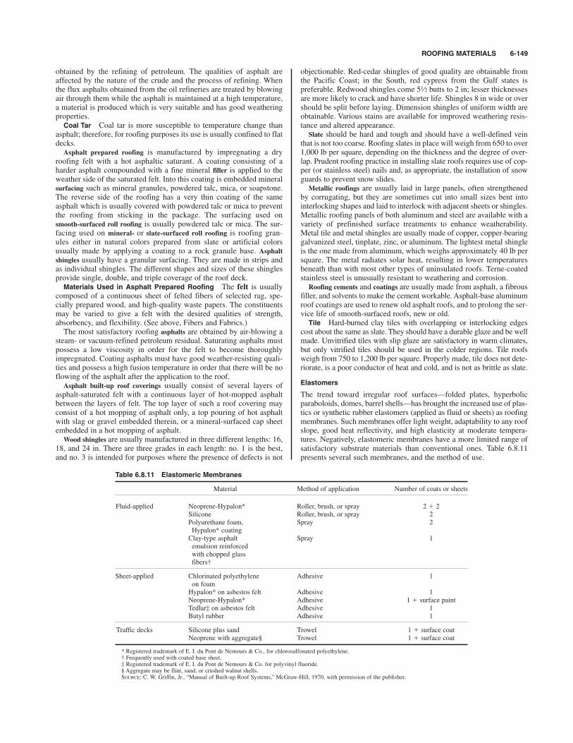
ROOFING MATERIALS 6-149
obtained by the refining of petroleum. The qualities of asphalt areaffected by the nature of the crude and the process of refining. Whenthe flux asphalts obtained from the oil refineries are treated by blowingair through them while the asphalt is maintained at a high temperature,a material is produced which is very suitable and has good weatheringproperties.
Coal Tar Coal tar is more susceptible to temperature change thanasphalt; therefore, for roofing purposes its use is usually confined to flatdecks.Asphalt prepared roofing is manufactured by impregnating a dry
roofing felt with a hot asphaltic saturant. A coating consisting of aharder asphalt compounded with a fine mineral filler is applied to theweather side of the saturated felt. Into this coating is embedded mineralsurfacing such as mineral granules, powdered talc, mica, or soapstone.The reverse side of the roofing has a very thin coating of the sameasphalt which is usually covered with powdered talc or mica to preventthe roofing from sticking in the package. The surfacing used onsmooth-surfaced roll roofing is usually powdered talc or mica. The sur-facing used on mineral- or slate-surfaced roll roofing is roofing gran-ules either in natural colors prepared from slate or artificial colorsusually made by applying a coating to a rock granule base. Asphaltshingles usually have a granular surfacing. They are made in strips andas individual shingles. The different shapes and sizes of these shinglesprovide single, double, and triple coverage of the roof deck.
Materials Used in Asphalt Prepared Roofing The felt is usuallycomposed of a continuous sheet of felted fibers of selected rag, spe-cially prepared wood, and high-quality waste papers. The constituentsmay be varied to give a felt with the desired qualities of strength,absorbency, and flexibility. (See above, Fibers and Fabrics.)The most satisfactory roofing asphalts are obtained by air-blowing a
steam- or vacuum-refined petroleum residual. Saturating asphalts mustpossess a low viscosity in order for the felt to become thoroughlyimpregnated. Coating asphalts must have good weather-resisting quali-ties and possess a high fusion temperature in order that there will be noflowing of the asphalt after the application to the roof.Asphalt built-up roof coverings usually consist of several layers of
asphalt-saturated felt with a continuous layer of hot-mopped asphaltbetween the layers of felt. The top layer of such a roof covering mayconsist of a hot mopping of asphalt only, a top pouring of hot asphaltwith slag or gravel embedded therein, or a mineral-surfaced cap sheetembedded in a hot mopping of asphalt.Wood shingles are usually manufactured in three different lengths: 16,
18, and 24 in. There are three grades in each length: no. 1 is the best,and no. 3 is intended for purposes where the presence of defects is not
objectionable. Red-cedar shingles of good quality are obtainable fromthe Pacific Coast; in the South, red cypress from the Gulf states ispreferable. Redwood shingles come butts to 2 in; lesser thicknessesare more likely to crack and have shorter life. Shingles 8 in wide or overshould be split before laying. Dimension shingles of uniform width areobtainable. Various stains are available for improved weathering resis-tance and altered appearance. Slate should be hard and tough and should have a well-defined vein
that is not too coarse. Roofing slates in place will weigh from 650 to over1,000 lb per square, depending on the thickness and the degree of over-lap. Prudent roofing practice in installing slate roofs requires use of cop-per (or stainless steel) nails and, as appropriate, the installation of snowguards to prevent snow slides.Metallic roofings are usually laid in large panels, often strengthened
by corrugating, but they are sometimes cut into small sizes bent intointerlocking shapes and laid to interlock with adjacent sheets or shingles.Metallic roofing panels of both aluminum and steel are available with avariety of prefinished surface treatments to enhance weatherability.Metal tile and metal shingles are usually made of copper, copper-bearinggalvanized steel, tinplate, zinc, or aluminum. The lightest metal shingleis the one made from aluminum, which weighs approximately 40 lb persquare. The metal radiates solar heat, resulting in lower temperaturesbeneath than with most other types of uninsulated roofs. Terne-coatedstainless steel is unusually resistant to weathering and corrosion.Roofing cements and coatings are usually made from asphalt, a fibrous
filler, and solvents to make the cement workable. Asphalt-base aluminumroof coatings are used to renew old asphalt roofs, and to prolong the ser-vice life of smooth-surfaced roofs, new or old.
Tile Hard-burned clay tiles with overlapping or interlocking edgescost about the same as slate. They should have a durable glaze and be wellmade. Unvitrified tiles with slip glaze are satisfactory in warm climates,but only vitrified tiles should be used in the colder regions. Tile roofsweigh from 750 to 1,200 lb per square. Properly made, tile does not dete-riorate, is a poor conductor of heat and cold, and is not as brittle as slate.
Elastomers
The trend toward irregular roof surfaces—folded plates, hyperbolicparaboloids, domes, barrel shells—has brought the increased use of plas-tics or synthetic rubber elastomers (applied as fluid or sheets) as roofingmembranes. Such membranes offer light weight, adaptability to any roofslope, good heat reflectivity, and high elasticity at moderate tempera-tures. Negatively, elastomeric membranes have a more limited range ofsatisfactory substrate materials than conventional ones. Table 6.8.11presents several such membranes, and the method of use.
51⁄2
Table 6.8.11 Elastomeric Membranes
Material Method of application Number of coats or sheets
Fluid-applied Neoprene-Hypalon* Roller, brush, or spray 2 & 2Silicone Roller, brush, or spray 2Polyurethane foam, Spray 2Hypalon* coatingClay-type asphalt Spray 1emulsion reinforcedwith chopped glassfibers†
Sheet-applied Chlorinated polyethylene Adhesive 1on foamHypalon* on asbestos felt Adhesive 1Neoprene-Hypalon* Adhesive 1 & surface paintTedlar‡ on asbestos felt Adhesive 1Butyl rubber Adhesive 1
Traffic decks Silicone plus sand Trowel 1 & surface coatNeoprene with aggregate§ Trowel 1 & surface coat
* Registered trademark of E. I. du Pont de Nemours & Co., for chlorosulfonated polyethylene.† Frequently used with coated base sheet.‡ Registered trademark of E. I. du Pont de Nemours & Co. for polyvinyl fluoride.§ Aggregate may be flint, sand, or crushed walnut shells.SOURCE: C. W. Griffin, Jr., “Manual of Built-up Roof Systems,” McGraw-Hill, 1970, with permission of the publisher.

RUBBER AND RUBBERLIKE MATERIALS(ELASTOMERS)
REFERENCES: Dawson and Porritt, “Rubber: Physical and Chemical Properties,”Research Association of British Rubber Manufacturers. Davis and Blake, “TheChemistry and Technology of Rubber,” Reinhold. ASTM Standards on RubberProducts. “Rubber Red Book Directory of the Rubber Industry,” The Rubber Age.Flint, “The Chemistry and Technology of Rubber Latex,” Van Nostrand. “TheVanderbilt Handbook,” R.T. Vanderbilt Co. Whitby, Davis, and Dunbrook,“Synthetic Rubber,” Wiley. “Rubber Bibliography,” Rubber Division, AmericanChemical Society. Noble, “Latex in Industry,” The Rubber Age. “Annual Reporton the Progress of Rubber Technology,” Institution of the Rubber Industry.Morton (ed.). “Rubber Technology,” Van Nostrand Reinhold. ISO 188–1982.“1986 Annual Book of ASTM Standards,” vols. 09.01, 09.02 (Rubber). CurrentASTM and ANSI Standards.
To avoid confusion by the use of the word rubber for a variety of nat-ural and synthetic products, the term elastomer has come into use, par-ticularly in scientific and technical literature, as a name for both naturaland synthetic materials which are elastic or resilient and in generalresemble natural rubber in feeling and appearance.The utility of rubber and synthetic elastomers is increased by com-
pounding. In the raw state, elastomers are soft and sticky when hot, andhard or brittle when cold. Vulcanization extends the temperature rangewithin which they are flexible and elastic. In addition to vulcanizingagents, ingredients are added to make elastomers stronger, tougher, andharder, to make them age better, to color them, and in general to modifythem to meet the needs of service conditions. Few rubber products todayare made from rubber or other elastomers alone.The elastomers of greatest commercial and technical importance
today are natural rubber, GR-S, Neoprene, nitrile rubbers, and butyl.Natural rubber of the best quality is prepared by coagulating the
latex of the Hevea brasilensis tree, cultivated chiefly in the Far East.This represents nearly all of the natural rubber on the market today.Unloaded vulcanized rubber will stretch to approximately 10 times its
length and at this point will bear a load of 13.8 % 106 N/m2 (10 tons/in2).It can be compressed to one-third its thickness thousands of times with-out injury. When most types of vulcanized rubber are stretched, theirresistance increases in greater proportion than the extension. Evenwhen stretched almost to the point of rupture, they recover very nearlytheir original dimensions on being released, and then gradually recovera part of the residual distortion.Freshly cut or torn raw rubber possesses the power of self-adhesion
which is practically absent in vulcanized rubber. Cold water preservesrubber, but if exposed to the air, particularly to the sun, rubber goods tendto become hard and brittle. Dry heat up to 49*C (120*F) has little deteri-orating effect; at temperatures of 181 to 204*C (360 to 400*F) rubberbegins to melt and becomes sticky; at higher temperatures, it becomesentirely carbonized. Unvulcanized rubber is soluble in gasoline, naphtha,carbon bisulfide, benzene, petroleum ether, turpentine, and other liquids.Most rubber is vulcanized, i.e., made to combine with sulfur or sulfur-
bearing organic compounds or with other chemical cross-linking agents.Vulcanization, if properly carried out, improves mechanical properties,eliminates tackiness, renders the rubber less susceptible to temperaturechanges, and makes it insoluble in all known solvents. It is impossibleto dissolve vulcanized rubber unless it is first decomposed. Other ingre-dients are added for general effects as follows:To increase tensile strength and resistance to abrasion: carbon black,
precipitated pigments, as well as organic vulcanization accelerators.To cheapen and stiffen: whiting, barytes, talc, silica, silicates, clays,
fibrous materials.To soften (for purposes of processing or for final properties): bitumi-
nous substances, coal tar and its products, vegetable and mineral oils,paraffin, petrolatum, petroleum oils, asphalt.Vulcanization accessories, dispersion and wetting mediums, etc.:
magnesium oxide, zinc oxide, litharge, lime, stearic and other organicacids, degras, pine tar.Protective agents (natural aging, sunlight, heat, flexing): condensa-
tion amines, waxes.
Coloring pigments: iron oxides, especially the red grades, lithopone,titanium oxide, chromium oxide, ultramarine blue, carbon and lamp-blacks, and organic pigments of various shades.Specifications should state suitable physical tests. Tensile strength
and extensibility tests are of importance and differ widely with differentcompounds.GR-S is an outgrowth and improvement of German Buna S. The
quantity now produced far exceeds all other synthetic elastomers. It ismade from butadiene and styrene, which are produced from petroleum.These two materials are copolymerized directly to GR-S, which isknown as a butadiene-styrene copolymer. GR-S has recently beenimproved, and now gives excellent results in tires.Neoprene is made from acetylene, which is converted to vinylacety-
lene, which in turn combines with hydrogen chloride to form chloro-prene. The latter is then polymerized to Neoprene.Nitrile rubbers, an outgrowth of German Buna N or Perbunan, are
made by a process similar to that for GR-S, except that acrylonitrile isused instead of styrene. This type of elastomer is a butadiene-acryloni-trile copolymer.Butyl, one of the most important of the synthetic elastomers, is made
from petroleum raw materials, the final process being the copolymeriza-tion of isobutylene with a very small proportion of butadiene or isoprene.Polysulfide rubbers having unique resistance to oxidation and to soft-
ening by solvents are commercially available and are sold under thetrademark Thiokol.Ethylene-propylene rubbers are notable in their oxidation resis-
tance. Polyurethane elastomers can have a tensile strength up to twicethat of conventional rubber, and solid articles as well as foamedshapes can be cast into the desired form using prepolymer shapes asstarting materials. Silicone rubbers have the advantages of a wide rangeof service temperatures and room-temperature curing. Fluorocarbonelastomers are available for high-temperature service. Polyester elas-tomers have excellent impact and abrasion resistance.No one of these elastomers is satisfactory for all kinds of service con-
ditions, but rubber products can be made to meet a large variety of ser-vice conditions.The following examples show some of the important properties
required of rubber products and some typical services where these prop-erties are of major importance:Resistance to abrasive wear: auto-tire treads, conveyor-belt covers,
soles and heels, cables, hose covers, V belts.Resistance to tearing: auto inner tubes, tire treads, footwear, hotwa-
ter bags, hose covers, belt covers, V belts.Resistance to flexing: auto tires, transmission belts, V belts, (see
Sec. 8.2 for information concerning types, sizes, strengths, etc., of V belts),mountings, footwear.Resistance to high temperatures: auto tires, auto inner tubes, belts
conveying hot materials, steam hose, steam packing.Resistance to cold: airplane parts, automotive parts, auto tires, refrig-
eration hose.Minimum heat buildup: auto tires, transmission belts, V belts, mount-
ings.High resilience: auto inner tubes, sponge rubber, mountings, elastic
bands, thread, sandblast hose, jar rings, V belts.High rigidity: packing, soles and heels, valve cups, suction hose, bat-
tery boxes.Long life: fire hose, transmission belts, tubing, V belts.Electrical resistivity: electricians’ tape, switchboard mats, electri-
cians’ gloves.Electrical conductivity: hospital flooring, nonstatic hose, matting.Impermeability to gases: balloons, life rafts, gasoline hose, special
diaphragms.Resistance to ozone: ignition distributor gaskets, ignition cables,
windshield wipers.Resistance to sunlight: wearing apparel, hose covers, bathing caps.Resistance to chemicals: tank linings, hose for chemicals.Resistance to oils: gasoline hose, oil-suction hose, paint hose, creamery
hose, packinghouse hose, special belts, tank linings, special footwear.
6-150 NONMETALLIC MATERIALS
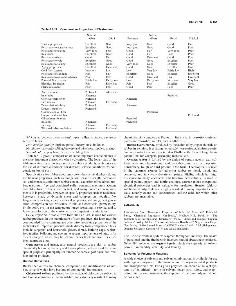
SOLVENTS 6-151
Stickiness: cements, electricians’ tapes, adhesive tapes, pressure-sensitive tapes.Low specific gravity: airplane parts, forestry hose, balloons.No odor or taste:milk tubing, brewery and wine hose, nipples, jar rings.Special colors: ponchos, life rafts, welding hose.Table 6.8.12 gives a comparison of some important characteristics of
the most important elastomers when vulcanized. The lower part of thetable indicates, for a few representative rubber products, preferences inthe use of different elastomers for different service conditions withoutconsideration of cost.Specifications for rubber goods may cover the chemical, physical, and
mechanical properties, such as elongation, tensile strength, permanentset, and oven tests, minimum rubber content, exclusion of reclaimed rub-ber, maximum free and combined sulfur contents, maximum acetoneand chloroform extracts, ash content, and many construction require-ments. It is preferable, however, to specify properties such as resilience,hysteresis, static or dynamic shear and compression modulus, flexfatigue and cracking, creep, electrical properties, stiffening, heat gener-ation, compression set, resistance to oils and chemicals, permeability,brittle point, etc., in the temperature range prevailing in service, and toleave the selection of the elastomer to a competent manufacturer.Latex, imported in stable form from the Far East, is used for various
rubber products. In the manufacture of such products, the latex must becompounded for vulcanizing and otherwise modifying properties of therubber itself. Important products made directly from compounded latexinclude surgeons’ and household gloves, thread, bathing caps, rubber-ized textiles, balloons, and sponge. A recent important use of latex is for“foam sponge,” which may be several inches thick and used for cush-ions, mattresses, etc.Gutta-percha and balata, also natural products, are akin to rubber
chemically but more leathery and thermoplastic, and are used for somespecial purposes, principally for submarine cables, golf balls, and var-ious minor products.
Rubber Derivatives
Rubber derivatives are chemical compounds and modifications of rub-ber, some of which have become of commercial importance.Chlorinated rubber, produced by the action of chlorine on rubber in
solution, is nonrubbery, incombustible, and extremely resistant to many
chemicals. As commercial Parlon, it finds use in corrosion-resistantpaints and varnishes, in inks, and in adhesives.Rubber hydrochloride, produced by the action of hydrogen chloride on
rubber in solution, is a strong, extensible, tear-resistant, moisture-resis-tant, oil-resistant material, marketed as Pliofilm in the form of tough trans-parent films for wrappers, packaging material, etc.Cyclized rubber is formed by the action of certain agents, e.g., sul-
fonic acids and chlorostannic acid, on rubber, and is a thermoplastic,nonrubbery, tough or hard product. One form, Thermoprene, is usedin the Vulcalock process for adhering rubber to metal, wood, andconcrete, and in chemical-resistant paints. Pliolite, which has highresistance to many chemicals and has low permeability, is used inspecial paints, paper, and fabric coatings. Marbon-B has exceptionalelectrical properties and is valuable for insulation. Hypalon (chloro-sulphonated polyethylene) is highly resistant to many important chem-icals, notably ozone and concentrated sulfuric acid, for which otherrubbers are unsuitable.
SOLVENTS
REFERENCES: Sax, “Dangerous Properties of Industrial Materials,” Reinhold.Perry, “Chemical Engineers’ Handbook,” McGraw-Hill. Doolittle, “TheTechnology of Solvents and Plasticizers,” Wiley. Riddick and Bunger, “OrganicSolvents,” Wiley. Mellan, “Industrial Solvents Handbook,” Noges Data Corp.,New Jersey. “1986 Annual Book of ASTM Standards,” vol: 15.05 (HalogenatedOrganic Solvents). Current ASTM and ANSI Standards.
The use of solvents is quite widespread throughout industry. The healthof personnel and the fire hazards involved should always be considered.Generally, solvents are organic liquids which vary greatly in solventpower, flammability, volatility, and toxicity.
Solvents for Polymeric Materials
A wide choice of solvents and solvent combinations is available for usewith organic polymers in the manufacture of polymer-coated productsand unsupported films. For a given polymer, the choice of solvent sys-tem is often critical in terms of solvent power, cost, safety, and evapo-ration rate. In such instances, the supplier of the base polymer shouldbe consulted.
Table 6.8.12 Comparative Properties of Elastomers
Natural Nitrilerubber GR-S Neoprene rubbers Butyl Thiokol
Tensile properties Excellent Good Very good Good Good FairResistance to abrasive wear Excellent Good Very good Good Good PoorResistance to tearing Very good Poor Good Fair Very good PoorResilience Excellent Good Good Fair Poor PoorResistance to heat Good Fair Good Excellent Good PoorResistance to cold Excellent Good Good Good Excellent PoorResistance to flexing Excellent Good Very good Good Excellent PoorAging properties Excellent Excellent Good Good Excellent GoodCold flow (creep) Very low Low Low Very low Fairly low HighResistance to sunlight Fair Fair Excellent Good Excellent ExcellentResistance to oils and solvents Poor Poor Good Excellent Fair ExcellentPermeability to gases Fairly low Fairly low Low Fairly low Very low Very lowElectrical insulation Fair Excellent Fair Poor Excellent GoodFlame resistance Poor Poor Good Poor Poor Poor
Auto tire tread Preferred AlternateInner tube Alternate PreferredConveyor-belt cover Preferred AlternateTire sidewall Alternate PreferredTransmission belting Preferred AlternateDruggist sundries PreferredGasoline and oil hose PreferredLacquer and paint hose PreferredOil-resistant footwear PreferredBalloons Alternate PreferredJar rings Alternate PreferredWire and cable insulation Alternate Preferred

Alcohols
Methyl alcohol (methanol) is now made synthetically. It is completelymiscible with water and most organic liquids. It evaporates rapidlyand is a good solvent for dyes, gums, shellac, nitrocellulose, and somevegetable waxes. It is widely used as an antifreeze for automobiles, inshellac solutions, spirit varnishes, stain and paint removers. It is toxic;imbibition or prolonged breathing of the vapors can cause blindness. Itshould be used only in well-ventilated spaces. Flash point 11*C (52*F).Ethyl alcohol (ethanol) is produced by fermentation and synthetically.
For industrial use it is generally denatured and sold under various tradenames. There are numerous formulations of specially denatured alco-hols which can legally be used for specified purposes.This compound is miscible with water and most organic solvents. It
evaporates rapidly and, because of its solvent power, low cost, andagreeable odor, finds a wide range of uses. The common uses areantifreeze (see Freezing Preventives, above), shellac solvent, in mixedsolvents, spirit varnishes, and solvent for dyes, oils, and animal greases.Denatured alcohols are toxic when taken orally. Ethyl alcohol vapors
when breathed in high concentration can produce the physiologicaleffects of alcoholic liquors. It should be used in well-ventilated areas.Flash point 15.3 to 16.7*C (960 to 62*F).Isopropyl alcohol (isopropanol) is derived mainly from petroleum
gases. It is not as good a solvent as denatured alcohol, although it canbe used as a substitute for ethyl alcohol in some instances. It is used asa rubbing alcohol and in lacquer thinners. Flash point is 11*C (52*F).Butyl alcohol (normal butanol) is used extensively in lacquer and
synthetic resin compositions and also in penetrating oils, metal cleaners,insect sprays, and paints for application over asphalt. It is an excellentblending agent for otherwise incompatible materials. Flash point is29*C (84*F).
Esters
Ethyl acetate dissolves a large variety of materials, such as nitrocelluloseoils, fats, gums, and resins. It is used extensively in nitrocellulose lac-quers, candy coatings, food flavorings, and in chemical synthesis. Onaccount of its high rate of evaporation, it finds a use in paper, leather,and cloth coatings and cements. Flash point $4.5*C (24*F).Butyl acetate is the acetic-acid ester of normal butanol. This ester is
used extensively for dissolving various cellulose esters, mineral andvegetable oils, and many synthetic resins, such as the vinylites, poly-styrene, methyl methacrylate, and chlorinated rubber. It is also a goodsolvent for natural resins. It is the most important solvent used in lac-quer manufacture. It is useful in the preparation of perfumes and syn-thetic flavors. Flash point 22.3*C (72*F).Amyl acetate, sometimes known as banana oil, is used mainly in lac-
quers. Its properties are somewhat like those of butyl acetate. Flashpoint 21.1*C (70*F).
Hydrocarbons
Some industrial materials can be dangerous, toxic, and carcinogenic.The reader should become familiar with the references listed underChlorinated Solvents in this section, which discuss the health hazardsof industrial materials.The aromatic hydrocarbons are derived from coal-tar distillates, the
most common of which are benzene, toluene, xylene (also known asbenzol, toluol, and xylol), and high-flash solvent naphtha.Benzene is an excellent solvent for fats, vegetable and mineral oils,
rubber, chlorinated rubber; it is also used as a solvent in paints, lac-quers, inks, paint removers, asphalt, coal tar. This substance should beused with caution. Flash point 12*F.Toluene General uses are about the same as benzol, in paints, lac-
quers, rubber solutions, and solvent extractions. Flash point 40*F.Xylene is used in the manufacture of dyestuffs and other synthetic
chemicals and as a solvent for paints, rubber, lacquer, and varnishes.Flash point 63 *F.Hi-flash naphtha or coal-tar naphtha is used mainly as a diluent in lac-
quers, synthetic enamels, paints, and asphaltic coatings. Flash point100*F.
Petroleum
These hydrocarbons, derived from petroleum, are, next to water, thecheapest and most universally used solvents.V. M. &. P. naphtha, sometimes called benzine, is used by paint and
varnish makers as a solvent or diluent. It finds wide use as a solventfor fats, oils, greases and is used as a diluent in paints and lacquers.It is also used as an extractive agent as well as in some specializedfields of cleansing (fat removal). It is used to compound rubbercement, inks, varnish removers. It is relatively nontoxic. Flash point20 to 45 *F.Mineral spirits, also called Stoddard solvent, is extensively used in
dry cleaning because of its high flash point and clean evaporation. It isalso widely used in turpentine substitutes for oil paints. Flash point 100to 110*F.Kerosine, a No. 1 fuel oil, is a good solvent for petroleum greases,
oils, and fats. Flash point 100 to 165*F.
Chlorinated Solvents
Solvents can pose serious health and environmental problems, thereforethe reader’s attention is called to the following publications: (1)“Industrial Health and Safety; Mutagens and Carcinogens; Solution;Toxicology,” vols. 1 to 3, Wiley. (2) “Patty’s Industrial Hygiene andToxicology,” vol. 1 (General Principles), vol. 2 (Toxicology), vol. 3(Industrial Hygiene Practices). (3) Peterson, “Industrial,” Prentice-Hall.(4) Sax and Lewis, “Dangerous Properties of Industrial Materials,”7th ed., Van Nostrand Reinhold. Section 18 of this handbook.The chlorinated hydrocarbons and fluorocarbon solvents are highly
proscribed for use in industry and in society in general because ofthe inherent health and/or environmental problems ascribed to them.These materials are highly regulated and when used should be han-dled with utmost care and under close supervision and accountablecontrol.Carbon tetrachloride is a colorless nonflammable liquid with a chlo-
roformlike odor. It is an excellent solvent for fats, oils, greases,waxes, and resins and was used in dry cleaning and in degreasing ofwool, cotton waste, and glue. It is also used in rubber cements andadhesives, as an extracting agent, and in fire extinguishers. It should beused only in well-ventilated spaces; prolonged inhalation is extremelydangerous.Trichlorethylene is somewhat similar to carbon tetrachloride but is
slower in evaporation rate. It is the solvent most commonly used forvapor degreasing of metal parts. It is also used in the manufacture ofdyestuffs and other chemicals. It is an excellent solvent and is used insome types of paints, varnishes, and leather coatings.Tetrachlorethylene, also called perchlorethylene, is nonflammable and
has uses similar to those of carbon tetrachloride and trichlorethylene. Itschief use is in dry cleaning; it is also used in metal degreasing.
Ketones
Acetone is an exceptionally active solvent for a wide variety of organicmaterials, gases, liquids, and solids. It is completely miscible withwater and also with most of the organic liquids. It can also be used asa blending agent for otherwise immiscible liquids. It is used in themanufacture of pharmaceuticals, dyestuffs, lubricating compounds,and pyroxylin compositions. It is a good solvent for cellulose acetate,ethyl cellulose, vinyl and methacrylate resins, chlorinated rubber,asphalt, camphor, and various esters of cellulose, including smokelesspowder, cordite, etc. Some of its more common uses are in paint andvarnish removers, the storing of acetylene, and the dewaxing of lubri-cating oils. It is the basic material for the manufacture of iodoformand chloroform. It is also used as a denaturant for ethyl alcohol. Flashpoint 0*F.Methylethylketone (MEK) can be used in many cases where acetone is
used as a general solvent, e.g., in the formulation of pyroxylin cementsand in compositions containing the various esters of cellulose. Flashpoint 30*F.Glycol ethers are useful as solvents for cellulose esters, lacquers, var-
nishes, enamels, wood stains, dyestuffs, and pharmaceuticals.
6-152 NONMETALLIC MATERIALS
THERMAL INSULATION 6-153
THERMAL INSULATION
REFERENCES: “Guide and Data Book,” ASHRAE. Glaser, “AerodynamicallyHeated Structures,” Prentice-Hall. Timmerhaus, “Advances in CryogenicEngineering,” Plenum. Wilkes, “Heat Insulation,” Wiley. Wilson, “IndustrialThermal Insulation,” McGraw-Hill. Technical Documentary Report ML-TDR-64–5, “Thermophysical Properties of Thermal Insulating Materials,” Air ForceMaterials Laboratory, Research and Technology Division, Air Force SystemsCommand; Prepared by Midwest Research Institute, Kansas City, MO. Probertand Hub (eds.), “Thermal Insulation,” Elsevier. Malloy, “Thermal Insulation,” VanNostrand Reinhold. “1986 Annual Book of ASTM Standards,” vol. 04.06 (ThermalInsulation). ANSI/ASTM Standards. Current ASTM and ANSI Standards.
Thermal insulation consisting of a single material, a mixture of materi-als, or a composite structure is chosen to reduce heat flow. Insulatingeffectiveness is judged on the basis of thermal conductivity anddepends on the physical and chemical structure of the material. Theheat transferred through an insulation results from solid conduction, gasconduction, and radiation. Solid conduction is reduced by small parti-cles or fibers in loose-fill insulation and by thin cell walls in foams.Gas conduction is reduced by providing large numbers of small pores(either interconnected or closed off from each other) of the order of themean free paths of the gas molecules, by substituting gases of lowthermal conductivity, or by evacuating the pores to a low pressure.Radiation is reduced by adding materials which absorb, reflect, orscatter radiant energy. (See also Sec. 4, Transmission of Heat byConduction and Convection.)The performance of insulations depends on the temperature of the
bounding surfaces and their emittance, the insulation density, the typeand pressure of gas within the pores, the moisture content, the thermalshock resistance, and the action of mechanical loads and vibrations. Intransient applications, the heat capacity of the insulation (affecting therate of heating or cooling) has to be considered.The form of the insulations can be loose fill (bubbles, fibers, flakes,
granules, powders), fiexible (batting, blanket, felt, multilayer sheets,and tubular), rigid (block, board, brick, custom-molded, sheet and pipecovering), cemented, foamed-in-place, or sprayed.The choice of insulations is dictated by the service-temperature range
as well as by design criteria and economic considerations.
Cryogenic Temperatures [below !1028C (!1508F)]
(See also Sec. 19.)
At the low temperatures experienced with cryogenic liquids, evacuatedmultilayer insulations, consisting of a series of radiation shields ofhigh reflectivity separated by low-conductivity spacers, are effectivematerials. Radiation shield materials are aluminum foils or aluminizedpolyester films used in combination with spacers of thin polyester fiberor glass-fiber papers; radiation shields of crinkled, aluminized polyesterfilm without spacers are also used. To be effective, multilayer insula-tions require a vacuum of at least 10$4 mmHg. Evacuated powder andfiber insulations can be effective at gas pressures up to 0.1 mmHg overa wide temperature range. Powders include colloidal silica (8 % 10$7 inparticle diam), silica aerogel (1 % 10$6 in), synthetic calcium silicate(0.001 in), and perlite (an expanded form of glassy volcanic lava parti-cles, 0.05 in diam). Powder insulations can be opacified with copper,aluminum, or carbon particles to reduce radiant energy transmission.Fiber insulations consist of mats of fibers arranged in ordered parallellayers either without binders or with a minimum of binders. Glass fibers(10$5 in diam) are used most frequently. For large process installationsand cold boxes, unevacuated perlite powder or mineral fibers are useful.Cellular glass (see Glass, this section) can be used for temperatures
as low as $450*F ($268*C) and has found use on liquefied natural gastank bases.Foamed organic plastics, using either fluorinated hydrocarbons or
other gases as expanding agents, are partially evacuated when gaseswithin the closed cells condense when exposed to low temperatures.Polystyrene and polyurethane foams are used frequently. Gastight barri-ers are required to prevent a rise in thermal conductivity with agingdue to diffusion of air and moisture into the foam insulation. Gas barriers
are made of aluminum foil, polyester film, and polyester film laminatedwith aluminum foil.
Refrigeration, Heating, and Air Conditioning up to 1208C (2508F)
At temperatures associated with commercial refrigeration practice andbuilding insulation, vapor barriers resistant to the diffusion of watervapor should be installed on the warm side of most types of insulationsif the temperature within the insulation is expected to fall below the dewpoint (this condition would lead to condensation of water vapor withinthe insulation and result in a substantial decrease in insulating effec-tiveness). Vapor barriers include oil- or tar-impregnated paper, paperlaminated with aluminum foil, and polyester films. Insulations whichhave an impervious outer skin or structure require a vaportight sealant atexposed joints to prevent collection of moisture or ice underneath theinsulation. (See also Secs. 12 and 19.) Loose-fill insulations include powders and granules such as perlite,
vermiculite (an expanded form of mica), silica aerogel, calcium silicate,expanded organic plastic beads, granulated cork (bark of the cork tree),granulated charcoal, redwood wool (fiberized bark of the redwoodtree), and synthetic fibers. The most widely used fibers are those madeof glass, rock, or slag produced by centrifugal attenuation or attenuationby hot gases.Flexible or blanket insulations include those made from organically
bonded glass fibers; rock wool, slag wool, macerated paper, or hairfelt placed between or bonded to paper laminate (including vapor-barrier material) or burlap; foamed organic plastics in sheet and padform (polyurethane, polyethylene); and elastomeric closed-cell foam insheet, pad, or tube form.Rigid or board insulations (obtainable in a wide range of densities
and structural properties) include foamed organic plastics such as poly-styrene (extended or molded beads); polyurethane, polyvinyl chloride,phenolics, and ureas; balsa wood, cellular glass, and corkboard (com-pressed mass of baked-cork particles).
Moderate Temperatures [up to 6508C (12008F)]
The widest use of a large variety of insulations is in the temperaturerange associated with power plants and industrial equipment. Inorganicinsulations are available for this temperature range, with several capa-ble of operating over a wider temperature range.Loose-fill insulations include diatomaceous silica (fossilized skele-
tons of microscopic organisms), perlite, vermiculite, and fibers of glass,rock, or slag. Board and blanket insulations of various shapes and degreesof flexibility and density include glass and mineral fibers, expandedperlite bonded with cellulose fiber and asphalt, organic bonded mineralfibers, and cellulose fiberboard.Sprayed insulation (macerated paper or fibers and adhesive or frothed
plastic foam), insulating concrete (concrete mixed with expanded perliteor vermiculite), and foamed-in-place plastic insulation (prepared by mix-ing polyurethane components, pouring the liquid mix into the void, andrelying on action of generated gas or vaporization of a low boiling flu-orocarbon to foam the liquid and fill the space to be insulated) are use-ful in special applications.Reflective insulations form air spaces bounded by surfaces of high
reflectivity to reduce the flow of radiant energy. Surfaces need not bemirror bright to reflect long-wavelength radiation emitted by objectsbelow 500*F. Materials for reflective insulation include aluminum foilcemented to one or both sides of kraft paper and aluminum particlesapplied to the paper with adhesive. Where several reflective surfaces areused, they have to be separated during the installation to form airspaces.Cellular glass can be used up to 900*F (482*C) alone and to 1,200*F
(649*C) or higher when combined with other insulating materials andjackets.
High Temperatures [above 8208C (1,5008F)]
At the high temperatures associated with furnaces and process applica-tions, physical and chemical stability of the insulation in an oxidizing,reducing, or neutral atmosphere or vacuum may be required. Loose-fillinsulations include glass fibers 538*C (1,000*F) useful temperature
limit, fibrous potassium titanate 1,040*C (1,900*F), alumina-silica fibers1,260*C (2,300*F), microquartz fibers, 1,370*C (2,500*F), opacified col-loidal alumina 1,310*C (2,400*F in vacuum), zirconia fibers 1,640*C(3,000*F), alumina bubbles 1,810*C (3,300*F), zirconia bubbles 2,360*C(4,300*F), and carbon and graphite fibers 2,480*C (4,500*F) in vacuumor an inert atmosphere.Rigid insulations include reinforced and bonded colloidal silica
1,090*C (2,000*F), bonded diatomaceous earth brick 1,370*C (2,500*F),insulating firebrick (see Refractories, below), and anisotropic pyroliticgraphite (100:1 ratio of thermal conductivity parallel to surface andacross thickness).Reflective insulations, forming either an airspace or an evacuated
chamber between spaced surfaces, include stainless steel, molybdenum,tantalum, or tungsten foils and sheets.Insulating cements are based on asbestos, mineral, or refractory fibers
bonded with mixtures of clay or sodium silicate. Lightweight, castableinsulating materials consisting of mineral or refractory fibers in a cal-cium aluminate cement are useful up to 2,500*F.Ablators are composite materials capable of withstanding high tem-
peratures and high gas velocities for limited periods with minimumerosion by subliming and charring at controlled rates. Materialsinclude asbestos, carbon, graphite, silica, nylon or glass fibers in ahigh-temperature resin matrix (epoxy or phenolic resin), and corkcompositions.
SILICONES
(See also discussion in Sealants later.)
Silicones are organosilicon oxide polymers characterized by remarkabletemperature stability, chemical inertness, waterproofness, and excellentdielectric properties. Among related products are the following:Water repellents in the form of extremely thin films which can be
formed on paper, cloth, ceramics, glass, plastics, leather, powders, orother surfaces. These have great value for the protection of delicateelectrical equipment in moist atmospheres.Oils with high flash points [above 315*C (600*F)], low pour points,
$84.3*C ($120*F), and with a constancy of viscosity notably superiorto petroleum products in the range from 260 to $73.3*C (500 to$100*F). These oil products are practically incombustible. They are inuse for hydraulic servomotor fluids, damping fluids, dielectric liquidsfor transformers, heat-transfer mediums, etc., and are of special value inaircraft because of the rapid and extreme temperature variations towhich aircraft are exposed. At present they are not available as lubri-cants except under light loads.Greases and compounds for plug cocks, spark plugs, and ball bearings
which must operate at extreme temperatures and speeds.Varnishes and resins for use in electrical insulation where tempera-
tures are high. Layers of glass cloth impregnated with or bounded bysilicone resins withstand prolonged exposure to temperatures up to260*C (500*F). They form paint finishes of great resistance to chemicalagents and to moisture. They have many other industrial uses.Silicone rubbers which retain their resiliency for $45 to 270*C ($50
to 520*F) but with much lower strength than some of the synthetic rub-bers. They are used for shaft seals, oven gaskets, refrigerator gaskets,and vacuum gaskets.
REFRACTORIES
REFERENCES: Buell, “The Open-Hearth Furnace,” 3 vols., Penton. Bull. R-2-E,The Babcock & Wilcox Co. “Refractories,” General Refractories Co. Chesters,“Steel Plant Refractories,” United Steel Companies, Ltd. “Modern RefractoryPractice,” Harbison Walker Refractories Co. Green and Stewart, “Ceramics: ASymposium,” British Ceramic Soc. ASTM Standards on Refractory Materials(Committee C-8). Trinks, “Industrial Furnaces,” vol. I, Wiley. Campbell, “HighTemperature Technology,” Wiley. Budnikov, “The Technology of Ceramics andRefractories,” MIT Press. Campbell and Sherwood (eds.), “High-TemperatureMaterials and Technology,” Wiley. Norton, “Refractories,” 4th ed., McGrawHill.Clauss, “Engineer’s Guide to High-Temperature Materials,” Addison-Wesley.
Shaw, “Refractories and Their Uses,” Wiley. Chesters, “Refractories; Productionand Properties,” The Iron and Steel Institute, London. “1986 Annual Book ofASTM Standards,” vol. 15.01 (Refractories). ANSI Standards B74.10–B74.8.Current ASTM and ANSI Standards.
Types of Refractories
Fire-Clay Refractories Fire-clay brick is made from fire clays,which comprise all refractory clays that are not white burning. Fireclays can be divided into plastic clays and hard flint clays; they mayalso be classified as to alumina content.Firebricks are usually made of a blended mixture of flint clays and
plastic clays which is then formed, after mixing with water, to therequired shape. Some or all of the flint clay may be replaced by highlyburned or calcined clay, called grog. A large proportion of modernbricks are molded by the dry press or power press process where theforming is carried out under high pressure and with a low water content.Some extruded and hand-molded bricks are still made.The dried bricks are burned in either periodic or tunnel kilns at tem-
peratures varying between 1,200 and 1,480*C (2,200 and 2,700*F).Tunnel kilns give continuous production and a uniform temperature ofburning.Fire-clay bricks are used for boiler settings, kilns, malleable-iron fur-
naces, incinerators, and many portions of steel and nonferrous metalfurnaces. They are resistant to spalling and stand up well under manyslag conditions, but are not generally suitable for use with high limeslags, fluid-coal ash slags, or under severe load conditions.High-alumina bricks are manufactured from raw materials rich in
alumina, such as diaspore and bauxite. They are graded into groupswith 50, 60, 70, 80, and 90 percent alumina content. When well fired,these bricks contain a large amount of mullite and less of the glassyphase than is present in firebricks. Corundum is also present in many ofthese bricks. High-alumina bricks are generally used for unusuallysevere temperature or load conditions. They are employed extensivelyin lime kilns and rotary cement kilns, the ports and regenerators of glasstanks, and for slag resistance in some metallurgical furnaces; their priceis higher than that for firebrick.Silica bricks are manufactured from crushed ganister rock containing
about 97 to 98 percent silica. A bond consisting of 2 percent lime isused, and the bricks are fired in periodic kilns at temperatures of 1,480to 1,540*C (2,700 to 2,800*F) for several days until a stable volume isobtained. They are especially valuable where good strength is requiredat high temperatures. Superduty silica bricks are finding some use in thesteel industry. They have a lowered alumina content and often a loweredporosity.Silica bricks are used extensively in coke ovens, the roofs and walls of
open-hearth furnaces, in the roofs and sidewalls of glass tanks, and aslinings of acid electric steel furnaces. Although silica brick is readilyspalled (cracked by a temperature change) below red heat, it is very sta-ble if the temperature is kept above this range, and for this reason standsup well in regenerative furnaces. Any structure of silica brick should beheated up slowly to the working temperature; a large structure oftenrequires 2 weeks or more to bring up.Magnesite bricks are made from crushed magnesium oxide which is
produced by calcining raw magnesite rock to high temperatures. Arock containing several percent of iron oxide is preferable, as this per-mits the rock to be fired at a lower temperature than if pure materialswere used. Magnesite bricks are generally fired at a comparativelyhigh temperature in periodic or tunnel kilns, though large tonnages ofunburned bricks are now produced. The latter are made with specialgrain sizing and a bond such as an oxychloride. A large proportion ofmagnesite brick made in this country uses raw material extracted fromseawater.Magnesite bricks are basic and are used whenever it is necessary to
resist high lime slags, e.g., formerly in the basic open-hearth furnace.They also find use in furnaces for the lead and copper refining industry.The highly pressed unburned bricks find extensive use as linings forcement kilns. Magnesite bricks are not so resistant to spalling as fire-clay bricks.
6-154 NONMETALLIC MATERIALS

REFRACTORIES 6-155
Dolomite This rock contains a mixture of Mg(OH)2 and Ca(OH2),is calcined, and is used in granulated form for furnace bottoms.Chrome bricks are manufactured in much the same way as magnesite
bricks but are made from natural chromite ore. Commercial ores alwayscontain magnesia and alumina. Unburned hydraulically pressed chromebricks are also made.Chrome bricks are very resistant to all types of slag. They are used as
separators between acid and basic refractories, also in soaking pits andfloors of forging furnaces. The unburned hydraulically pressed bricksnow find extensive use in the walls of the open-hearth furnace and areoften enclosed in a metal case. Chrome bricks are used in sulfite recov-ery furnaces and to some extent in the refining of nonferrous metals.The insulating firebrick is a class of brick which consists of a highly
porous fire clay or kaolin. They are lightweight (about one-half toone-sixth that of fireclay), low in thermal conductivity, and yet suffi-ciently resistant to temperature to be used successfully on the hot sideof the furnace wall, thus permitting thin walls of low thermal conduc-tivity and low heat content. The low heat content is particularly valuablein saving fuel and time on heating up, allows rapid changes in temper-ature to be made, and permits rapid cooling. These bricks are made ina variety of ways, such as mixing organic matter with the clay and laterburning it out to form pores; or a bubble structure can be incorporatedin the clay-water mixture which is later preserved in the fired brick. Theinsulating firebricks are classified into several groups according to themaximum use limit; the ranges are up to 872, 1,090, 1,260, 1,420, andabove 1,540*C (1,600, 2,000, 2,300, 2,600, and above 2,800*F).Insulating refractories are used mainly in the heat-treating industry
for furnaces of the periodic type; the low heat content permits notewor-thy fuel savings as compared with firebrick. They are also extensivelyin stress-relieving furnaces, chemical-process furnaces, oil stills orheaters, and in the combustion chambers of domestic-oilburnerfurnaces. They usually have a life equal to the heavy bricks that they
replace. They are particularly suitable for constructing experimental orlaboratory furnaces because they can be cut or machined readily to anyshape. However, they are not resistant to fluid slag.There are a number of types of special brick, obtainable from individ-
ual manufactories. High burned kaolin refractories are particularlyvaluable under conditions of severe temperature and heavy load, orsevere spalling conditions, as in the case of high temperature oil-firedboiler settings, or piers under enameling furnaces. Another brick for thesame uses is a high-fired brick of Missouri aluminous clay.Bricks of silicon carbon, either nitride or clay bonded, have a high
thermal conductivity and find use in muffle walls and as a slag-resistingmaterial.Other types of refractory that find certain limited use are forsterite
and zirconia. Acid-resisting bricks consisting of a dense body likestoneware are used for lining tanks and conduits in the chemicalindustry. Carbon blocks are used as linings for the crucibles of blastfurnaces.The chemical composition of some of the refractories is given in Table
6.8.13. The physical properties are given in Table 6.8.14. Referenceshould be made to ASTM Standards for details of standard tests, and toANSI Standards for further specifications and properties.
Standard and Special Shapes
There are a large number of standard refractory shapes carried in stockby most manufacturers. Their catalogs should be consulted in selectingthese shapes, but the common ones are shown in Table 6.8.15. Theseshapes have been standardized by the American Refractories Instituteand by the Bureau of Simplification of the U.S. Department ofCommerce.Regenerator tile sizes a % b % c are: 18 % 6 or 9 % 3; 18 % 9 or
12 % 4; 22 % 6 or 9 % 3; 22 % 9 or 12 % 4; 27 % 9 % 3; 27 % 9or 12 % 4; 31 % 12 % 4; 36 % 12 % 4.1⁄2
1⁄21⁄2
Table 6.8.13 Chemical Composition of Typical Refractories*
Resistance to:
1 Alumina (fused) 8–10 85–90 1–1.5 1.5–2.2 . . . . . . . . . . . . . . . 0.8–1.3‡ E G F G2 Chrome 6 23 15† . . . . . . . . . . 17 38 . . . . . . . . . . . . . . G E E G3 Chrome (unburned) 5 18 12† . . . . . . . . . . 32 30 . . . . . . . . . . . . . . G E E G4 Fireclay (high-heat 50–57 36–42 1.5–2.5 1.5–2.5 . . . . . . . . . . . . . . . 1–3.5‡ F P P F
duty)5 Fireclay (super- 52 43 1 2 . . . . . . . . . . . . . . . 2‡ F P F F
duty)6 Forsterite 34.6 0.9 7.0 . . . . . . . 1.3 55.47 High-alumina 22–26 68–72 1–1.5 3.5 . . . . . . . . . . . . . . . 1–1.5‡ G F F F8 Kaolin 52 45.4 0.6 1.7 0.1 0.2 . . . . . . . . . . . . . . . . F P G§ F9 Magnesite 3 2 6 . . . . . . . 3 86 . . . . . . . . . . . . . . . . P E E E10 Magnesite 5 7.5 8.5 . . . . . . . 2 64 10 . . . . . . . . . . . . . . P E E E
(un-burned)11 Magnesite (fused) . . . . . . . . . . . . . . . . . . . . . . . . . . . . . . . . . . . . . . . . . . . . . . . . . F E E E12 Refractory 25–70 25–60 . . . . . . . . . . . . . . . . . . . . . . . . . . . . . 1–5 G F F F
porcelain13 Silica 96 1 1 . . . . . . . 2 . . . . . . . . . . . . . . . . . . . . E P F P14 Silicon carbide 7–9 2–4 0.3–1 1 . . . . . . . . . 85–90 . . . . . . . . E G F E
(clay-bonded)15 Sillimanite 35 62 0.5 1.5 . . . . . . . . . . . . . . . 0.5§ G F F F
(mullite)16 Insulating firebrick 57.7 36.8 2.4 1.5 0.6 0.5 . . . . . . . . . . . . . . . . P P G¶ F
(2,6008F)
E # excellent. G # good. F # fair. P # poor.* Many of these data have been taken from a table prepared by Trostel, Chem. Met. Eng., Nov. 1938.† As FeO.‡ Includes lime and magnesia.§ Excellent if left above 1,200*F.¶ Oxidizing atmosphere.
Coal-ash
slag
Fused
mill-scale
High-lime
steel-slag
Siliceous
steel-slag
Alkalies
SiC
Cr 2O3
MgO
CaO
TiO
2
Fe 2O3
Al 2O3
SiO
2
Refractory typeNo.
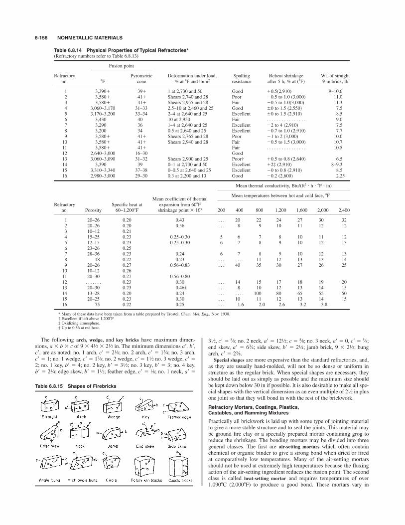
The following arch, wedge, and key bricks have maximum dimen-sions, a % b % c of 9 % 4 % 2 in. The minimum dimensions a+, b+,c+, are as noted: no. 1 arch, c+ # 2 ; no. 2 arch, c+ # 1 ; no. 3 arch,c+ # 1; no. 1 wedge, c+ # 1 ; no. 2 wedge, c’# 1 no. 3 wedge, c+ #2; no. 1 key, b+ # 4; no. 2 key, b+ # 3 ; no. 3 key, b+ # 3; no. 4 key,b+ # 2 ; edge skew, b+ # 1 ; feather edge, c+ # ; no. 1 neck, a+ #1⁄81⁄21⁄4
1⁄2
1⁄27⁄8
3⁄41⁄8
1⁄21⁄23 , c+ # ; no. 2 neck, a+ # 12 ; c # ; no. 3 neck, a+ # 0, c+ # ;end skew, a+ # 6 ; side skew, b+ # 2 ; jamb brick, 9 % 2 ; bungarch, c+ # 2 .Special shapes are more expensive than the standard refractories, and,
as they are usually hand-molded, will not be so dense or uniform instructure as the regular brick. When special shapes are necessary, theyshould be laid out as simply as possible and the maximum size shouldbe kept down below 30 in if possible. It is also desirable to make all spe-cial shapes with the vertical dimension as an even multiple of 2 in plusone joint so that they will bond in with the rest of the brickwork.
Refractory Mortars, Coatings, Plastics,Castables, and Ramming Mixtures
Practically all brickwork is laid up with some type of jointing materialto give a more stable structure and to seal the joints. This material maybe ground fire clay or a specially prepared mortar containing grog toreduce the shrinkage. The bonding mortars may be divided into threegeneral classes. The first are air-setting mortars which often containchemical or organic binder to give a strong bond when dried or firedat comparatively low temperatures. Many of the air-setting mortarsshould not be used at extremely high temperatures because the fluxingaction of the air-setting ingredient reduces the fusion point. The secondclass is called heat-setting mortar and requires temperatures of over1,090*C (2,000*F) to produce a good bond. These mortars vary in
1⁄2
3⁄8
1⁄21⁄43⁄4
5⁄85⁄81⁄25⁄81⁄2
6-156 NONMETALLIC MATERIALS
Table 6.8.14 Physical Properties of Typical Refractories*(Refractory numbers refer to Table 6.8.13)
Fusion point
Refractory Pyrometric Deformation under load, Spalling Reheat shrinkage Wt. of straightno. 8F cone % at 8F and lb/in2 resistance after 5 h, % at (8F) 9-in brick, lb
1 3,390& 39& 1 at 2,730 and 50 Good &0.5(2,910) 9–10.62 3,580& 41& Shears 2,740 and 28 Poor $0.5 to 1.0 (3,000) 11.03 3,580& 41& Shears 2,955 and 28 Fair $0.5 to 1.0(3,000) 11.34 3,060–3,170 31–33 2.5–10 at 2,460 and 25 Good ,0 to 1.5 (2,550) 7.55 3,170–3,200 33–34 2–4 at 2,640 and 25 Excellent ,0 to 1.5 (2,910) 8.56 3,430 40 10 at 2,950 Fair . . . . . . . . . . . . . . . . 9.07 3,290 36 1–4 at 2,640 and 25 Excellent $2 to 4 (2,910) 7.58 3,200 34 0.5 at 2,640 and 25 Excellent $0.7 to 1.0 (2,910) 7.79 3,580& 41& Shears 2,765 and 28 Poor $1 to 2 (3,000) 10.010 3,580& 41& Shears 2,940 and 28 Fair $0.5 to 1.5 (3,000) 10.711 3,580& 41& Fair . . . . . . . . . . . . . . . . 10.512 2,640–3,000 16–30 Good13 3,060–3,090 31–32 Shears 2,900 and 25 Poor† &0.5 to 0.8 (2,640) 6.514 3,390 39 0–1 at 2,730 and 50 Excellent &2‡ (2,910) 8–9.315 3,310–3,340 37–38 0–0.5 at 2,640 and 25 Excellent $0 to 0.8 (2,910) 8.516 2,980–3,000 29–30 0.3 at 2,200 and 10 Good $0.2 (2,600) 2.25
Mean thermal conductivity, Btu/(ft2 ' h ' *F ' in)
Mean coefficient of thermalMean temperatures between hot and cold face, *F
Refractory Specific heat at expansion from 60*Fno. Porosity 60–1,200*F shrinkage point % 105 200 400 800 1,200 1,600 2,000 2,400
1 20–26 0.20 0.43 . . . 20 22 24 27 30 322 20–26 0.20 0.56 . . . 8 9 10 11 12 123 10–12 0.214 15–25 0.23 0.25–0.30 5 6 7 8 10 11 125 12–15 0.23 0.25–0.30 6 7 8 9 10 12 136 23–26 0.257 28–36 0.23 0.24 6 7 8 9 10 12 138 18 0.22 0.23 . . . . . . . 11 12 13 13 149 20–26 0.27 0.56–0.83 . . . 40 35 30 27 26 2510 10–12 0.2611 20–30 0.27 0.56–0.8012 . . . . . . . 0.23 0.30 . . . 14 15 17 18 19 2013 20–30 0.23 0.46§ . . . 8 10 12 13 14 1514 13–28 0.20 0.24 . . . . . . . 100 80 65 55 5015 20–25 0.23 0.30 . . . 10 11 12 13 14 1516 75 0.22 0.25 . . . 1.6 2.0 2.6 3.2 3.8
* Many of these data have been taken from a table prepared by Trostel, Chem. Met. Eng., Nov. 1938.† Excellent if left above 1,200*F‡ Oxidizing atmosphere.§ Up to 0.56 at red heat.
Table 6.8.15 Shapes of Firebricks

REFRACTORIES 6-157
vitrifying point, some producing a strong bond in the lower temperatureranges, and the others requiring very high temperatures to give goodstrength. The third classification comprises special base mortars suchas silica, magnesite, silicon carbide, or chrome, which are speciallyblended for use with their respective bricks. The chrome-base mortarmay be satisfactorily used with fire-clay bricks in many cases. The refractory bonding mortars should preferably be selected on the
advice of the manufacturer of the refractory to obtain good service,although there are a considerable number of independent manufacturersof mortars who supply an excellent product. From 1,330 to 1,778 N(300 to 400 lb) of dry mortar per 1,000 bricks is required for thin joints,which are desirable in most furnace construction. For thicker troweljoints, up to 2,220 N (500 lb) per 1,000 bricks is required. In the caseof chrome base mortars, 2,660 N (600 lb) per 1,000 bricks should beallowed, and for magnesite cement 3,550 N (800 lb) per 1,000 bricks.Coatings are used to protect the hot surface of the refractories, espe-
cially when they are exposed to dust-laden gases or slags. These coat-ings usually consist of ground grog and fireclay of a somewhat coarsertexture than the mortar. There are also chrome-base coatings which arequite resistant to slags, and in a few cases natural clays containing silicaand feldspar are satisfactory.The coatings can be applied to the surface of the brickwork with a
brush in thin layers about in thick, or they may be sprayed on witha cement gun, the latter method generally giving the best results. Sometypes of coating can be put on in much thicker layers, but care shouldbe taken to assure that the coating selected will fit the particular brickused; otherwise it is apt to peel off in service.Plastics and ramming mixtures are generally a mixture of fire clay
and coarse grog of somewhat the same composition as the original fire-clay brick. They are used in repairing furnace walls which have beendamaged by spalling or slag erosion, and also for making complete
1⁄16
furnace walls in certain installations such as small boiler furnaces. Theyare also used to form special or irregular shapes, in temporary woodenforms, in the actual furnace construction.Some of the plastics and ramming mixtures contain silicate of soda
and are air-setting, so that a strong structure is produced as soon as thematerial is dry. Others have as a base chrome ore or silicon carbide,which make a mixture having a high thermal conductivity and a goodresistance to slag erosion. These mixtures are often used in the waterwalls of large boiler furnaces; they are rammed around the tubes andheld in place by small studs welded to the tube walls. The chrome plas-tic has been used with good success for heating-furnace floors and sub-hearths of open-hearth furnaces.Castable mixes are a refractory concrete usually containing high-
alumina cement to give the setting properties. These find considerableuse in forming intricate furnace parts in wooden molds; large structureshave been satisfactorily cast by this method. This type of mixture ismuch used for baffles in boilers where it can be cast in place around thetubes. Lightweight castables with good insulating properties are used toline furnace doors.
Furnace Walls
The modern tendency in furnace construction is to make a compara-tively thin wall, anchored and supported at frequent intervals by cast-ings or heat-resisting alloys which, in turn, are held by a structuralframework and does not rest on the base. The wall may be made ofheavy refractories backed up with insulating material, or of insulatingrefractory. Table 6.8.16 gives heat losses and heat contents of a numberof wall combinations and may enable designers to pick out a wall sectionto suit their purpose. Solid walls built with standard 9-in brick are madeup in various ways, but the hot face has usually four header courses andone stretcher course alternating.
Table 6.8.16 Transmitted Heat Losses and Heat-Storage Capacities of Wall Structures under EquilibriumConditions(Based on still air at 80*F)
Thickness, in Hot face temperature, 8F
Of insulating 1,200 1,600 2,000 2,400 2,800refractory and
Wall firebrick HL HS HL HS HL HS HL HS HL HS
20 355 1,600 537 2,300 755 2,90028 441 2,200 658 3,100 932 4,000 1,241 4,900 1,589 5,900FB 1,180 8,400 1,870 11,700 2,660 14,800 3,600 18,100 4,640 21,600
7 28 & 20 265 3,500 408 4,900 567 6,500 751 8,100 970 9,800FB 423 12,500 660 17,700 917 23,000 1,248 28,200
9 28 & 20 203 4,100 311 5,900 432 7,900 573 9,900 738 12,200FB & 20 285 13,700 437 19,200 615 24,800
9 20 181 3,100 280 4,300 395 5,5009 28 233 4,100 349 5,800 480 7,500 642 9,300 818 11,1009 FB 658 15,800 1,015 21,600 1,430 27,600 1,900 34,000 2,480 40,300
9 28 & 20 169 5,700 260 8,000 364 10,500 484 13,100 623 15,8009 FB & 20 335 22,300 514 31,400 718 40,600 962 50,400 1,233 60,3009 28 & 20 143 6,500 217 9,300 305 12,300 404 15,300 514 18,7009 FB & 20 241 24,100 367 34,500 516 44,800 690 55,100
9 20 & FB 165 5,300 255 7,300 348 9,9009 28 & FB 200 6,900 302 9,700 415 12,600 556 15,700 710 19,100
FB 452 22,300 700 31,000 980 39,900 1,310 49,100 1,683 58,300
16 FB & 20 275 31,200 423 43,300 588 56,300 780 70,000 994 84,200
18 9 20 & 9 FB 147 8,500 225 11,900 319 15,7009 28 & 9 FB 175 10,700 266 15,100 375 19,700 493 24,600 635 29,800
FB & 20 210 34,100 318 48,400 440 62,600 587 77,500 753 92,60018 FB 355 28,800 532 40,300 745 52,200 1,000 64,200 1,283 76,500
18 FB & 20 234 39,000 356 55,400 500 72,000 665 89,200 847 107,000
18 FB & 20 182 43,200 281 61,000 392 79,200 519 97,700 667 117,600FB 287 36,000 435 49,500 612 64,100 814 78,800 1,040 93,400
Conversion factors: tc # (tF $ 32); 1 in # 0.0254 m.HL # heat loss in Btu/(ft2)/(h). HS # heat storage capacity in Btu/ft2. 20 # 2,000*F insulating refractory. 28 # 2,800*F insulating refractory. FB # fireclay brick.SOURCE: Condensed from “B & W Insulating Firebrick” Bulletin of The Babcock & Wilcox Co.
5⁄9
221⁄241⁄2221⁄2
21⁄2201⁄2
41⁄2131⁄2
21⁄2131⁄2
131⁄241⁄241⁄2131⁄2
41⁄241⁄221⁄221⁄2111⁄2
41⁄241⁄241⁄241⁄2
41⁄221⁄241⁄2
41⁄241⁄241⁄241⁄2

Many modern furnaces are constructed with air-cooled walls, withrefractory blocks held in place against a casing by alloy steel holders.Sectional walls made up with steel panels having lightweight insulatingrefractories attached to the inner surface are also used and are especiallyvaluable for use in the upper parts of large boiler furnaces, oil stills, andsimilar types of construction. The sections can be made up at the plantand shipped as a unit. They have the advantage of low cost because ofthe light ironwork required to support them.Many failures in furnace construction result from improper expan-
sion joints. Expansion joints should usually be installed at least every10 ft, although in some low-temperature structures the spacing may begreater. For high-temperature construction, the expansion jointallowance per foot in inches should be as follows: fire clay, to ;high alumina, to ; silica, to ; magnesite, ; chrome, ;forsterite, . Corrugated paper is often used in the joints.The roof of the furnace is usually either a sprung arch or a suspended
arch. A sprung arch is generally made of standard shapes using an insideradius equal to the total span. In most cases, it is necessary to build aform on which the arch is sprung.In the case of arches with a considerable rise, it has been found that
an inverted catenary shape is better than a circular shape for stability,and it is possible to run the sidewalls of the furnace right down to thefloor in one continuous arch with almost complete elimination of theironwork. The catenary can be readily laid out by hanging a flexiblechain from two points of a vertical wall.The suspended arch is used when it is desirable to have a flat roof
(curved suspended arches are also made); it presents certain advantagesin construction and repair but is more difficult to insulate than thesprung arch. Special suspended arch shapes are commercially available.The insulating refractory is suited to this type of construction becausethe steel supports are light and the heat loss is low.
Selection of Refractories
The selection of the most suitable refractory for a given purposedemands experience in furnace construction. A brick that costs twice asmuch as another brand and gives twice the life is preferable since thetotal cost includes the laying cost. Furthermore, a brick that giveslonger service reduces the shutdown period of the furnace. Where slagor abrasion is severe, brick with a dense structure is desirable. Ifspalling conditions are important, a brick with a more flexible structureis better, although there are cases where a very dense structure givesbetter spalling resistance than a more open one.High-lime slag can be taken care of with magnesite, chrome, or high-
alumina brick, but if severe temperature fluctuations are encounteredalso, no brick will give long life. For coal-ash slag, dense fire-claybricks give fairly good service if the temperature is not high. At thehigher temperatures, a chrome-plastic or silicon carbide refractory oftenproves successful. When the conditions are unusually severe, air- orwater-cooled walls must be resorted to; the water-cooled stud-tube wallhas been very successful in boiler furnaces.With a general freedom from slag, it is often most economical to use
an insulating refractory. Although this brick may cost more per unit, itallows thinner walls, so that the total construction cost may be no greaterthan the regular brick. The substitution of insulating refractory for heavybrick in periodic furnaces has sometimes halved the fuel consumption.The stability of a refractory installation depends largely on the brick-
laying. The total cost, in addition to the bricks, of laying brick varieswith the type of construction, locality, and refractory.
Recent Developments in Refractories
Pure-oxide refractories have been developed to permit fabrication ofparts such as tubes, crucibles, and special shapes. Alumina (A12O3) isthe most readily formed into nonporous pieces and, up to its softeningpoint of 2,040*C (3,690*F), is most useful. Mullite (2SiO2 :3Al2O3),softening at 1,820*C (3,290*F), is used for thermocouple protectiontubes, crucibles, and other small pieces. Magnesium oxide (MgO), fus-ing at 2,800*C (5,070*F), is resistant to metals and slags. Zirconia(ZrO2), softening at 4,600*F, is very sensitive to temperature changes
1⁄4
5⁄321⁄43⁄161⁄81⁄83⁄32
3⁄321⁄16
but can be stabilized with a few percent of lime. Beryllium oxide (BeO),softening at 2,570*C (4,660*F), has a very high thermal conductivity butmust be fabricated with great care because of health hazards. Thoria(ThO2) softens at 3,040*C (5,520*F) and has been used in crucibles formelting active metals and as a potential nuclear fuel.Refractory carbides, sulfides, borides, silicides, and nitrides have been
developed for special uses. Many have high softening points, but allhave limited stability in an oxidizing atmosphere. Silicon carbide (SiC)is the most used because of its high thermal and electrical conductivity,its resistance against certain slags, and its relatively good stability in air.Molybdenum silicide (MoSi2) also has considerable resistance tooxidation and, like SiC, can be used for metal-melting crucibles.Cerium sulfide (CeS2) is a metallic-appearing material of high soften-ing point but no resistance to oxidation. Zirconium nitride (ZrN) andtitanium nitride (TiN) are also metalliclike but are not stable whenheated in air. Graphite has valuable and well-known refractory proper-ties but is not resistant to oxidation.Refractory fibers are coming into use quite extensively. Fibers of
silica-alumina glass have a use limit of about 1,090*C (2,000*F). Theyare used for insulating blankets, expansion joints, and other high tem-perature insulation. Development of higher-temperature fibers is beingcarried out on a small scale for use as high temperature insulation ormechanical reenforcement.Nuclear fuels of uranium, thorium, and plutonium oxides or carbides
are now extensively used in high temperature reactors.Space vehicles are using nozzles of refractories of various kinds to
withstand the high temperatures and erosion. Nose cones of sinteredalumina are now used extensively because of their excellent refractoryand electrical properties. Heat shields to protect space vehicles uponreentry are an important use of special refractories.
Physical Properties of High-Purity Refractories
In Table 6.8.17 are shown the properties of some of the more importantpure refractory materials. It should be realized that, as purer materialsbecome available and testing methods become more refined, some ofthese values will change.
SEALANTS
REFERENCES: Damusis (ed.), “Sealants,” Reinhold. Flick, “Adhesives and SealantCompound Formulations,” 2d ed., Noyes Publ. Mech. Eng., April 1991. Engr.News Record, Nov. 12, 1987; 1972–1993 “Annual Book of ASTM Standards.”Baldwin, Selecting High Performance Building Sealants, Plant Eng., Jan. 1976,pp. 58–62. Panek and Cook, “Construction Sealants and Adhesives,” 2d ed, Wiley-Interscience. Panek (ed.), Building Seals and Sealants, ASTM Spec. Tech. Publ.606, American Society for Testing Materials, Philadelphia. Klosowski, “Sealantsin Construction,” Marcel Dekker. Current ASTM and ANSI Standards.
Klosowski’s book is an excellent source of information on sealants andserves as an excellent reference. The reader should treat the followingmaterial as a guide and should consult the references and manufacturers’catalogs for expanded coverage.Classifying sealants is somewhat arbitrary, depending as such on a
multitude of properties. One of these properties tends to be more impor-tant than the rest, and that is the ability to take cyclic movement. Lowmovement ability together with short useful lifetimes tends to be foundfor the lower-cost sealants, and ability to take cyclic movement alongwith long useful lifetimes is found for the higher-cost sealants. Theremaining key properties are adhesion/cohesion, hardness, modulus,stress relaxation, compression set, and weather resistance. Table 6.8.18provides a rough comparison of sealant classes.
Key Properties
Adhesion/Cohesion A sealant must stick or adhere to the jointmaterials to prevent fluid penetration. The sealant must also stick orcohere to itself internally so that it does not split apart and thus allowleakage to occur. The ASTM C-719 test method is recommended forcrucial designs and applications.
6-158 NONMETALLIC MATERIALS
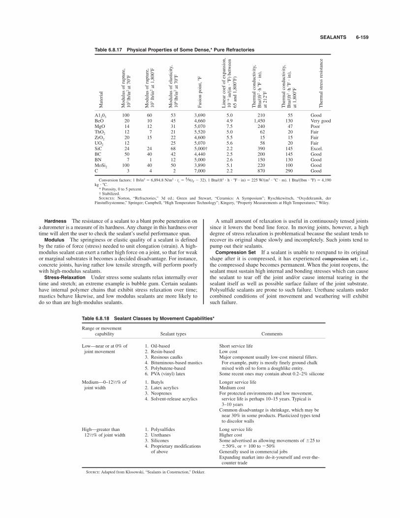
SEALANTS 6-159
Hardness The resistance of a sealant to a blunt probe penetration ona durometer is a measure of its hardness. Any change in this hardness overtime will alert the user to check the sealant’s useful performance span.
Modulus The springiness or elastic quality of a sealant is definedby the ratio of force (stress) needed to unit elongation (strain). A high-modulus sealant can exert a rather high force on a joint, so that for weakor marginal substrates it becomes a decided disadvantage. For instance,concrete joints, having rather low tensile strength, will perform poorlywith high-modulus sealants.
Stress-Relaxation Under stress some sealants relax internally overtime and stretch; an extreme example is bubble gum. Certain sealantshave internal polymer chains that exhibit stress relaxation over time;mastics behave likewise, and low modulus sealants are more likely todo so than are high-modulus sealants.
A small amount of relaxation is useful in continuously tensed jointssince it lowers the bond line force. In moving joints, however, a highdegree of stress relaxation is problematical because the sealant tends torecover its original shape slowly and incompletely. Such joints tend topump out their sealants.
Compression Set If a sealant is unable to reexpand to its originalshape after it is compressed, it has experienced compression set; i.e.,the compressed shape becomes permanent. When the joint reopens, thesealant must sustain high internal and bonding stresses which can causethe sealant to tear off the joint and/or cause internal tearing in thesealant itself as well as possible surface failure of the joint substrate.Polysulfide sealants are prone to such failure. Urethane sealants undercombined conditions of joint movement and weathering will exhibitsuch failure.
Table 6.8.17 Physical Properties of Some Dense,* Pure Refractories
A1203 100 60 53 3,690 5.0 210 55 GoodBeO 20 10 45 4,660 4.9 1,450 130 Very goodMgO 14 12 31 5,070 7.5 240 47 PoorThO2 12 7 21 5,520 5.0 62 20 FairZrO2 20 15 22 4,600 5.5 15 15 FairUO2 12 25 5,070 5.6 58 20 FairSiC 24 24 68 5,000† 2.2 390 145 Excel.BC 50 40 42 4,440 2.5 200 145 GoodBN 7 1 12 5,000 2.6 150 130 GoodMoSi2 100 40 50 3,890 5.1 220 100 GoodC 3 4 2 7,000 2.2 870 290 Good
Conversion factors: 1 lb/in2 # 6,894.8 N/m2 ' tc # (tF $ 32). 1 Btu/(ft2 ' h ' *F ' in) # 225 W/(m2 ' *C ' m). 1 Btu/(lbm ' *F) # 4,190kg ' *C.* Porosity, 0 to 5 percent.† Stabilized.SOURCES: Norton, “Refractories,” 3d ed.; Green and Stewart, “Ceramics: A Symposium”; Ryschkewitsch, “Oxydekramik, der
Finstuffsystemme,” Springer; Campbell, “High Temperature Technology”; Kingery, “Property Measurements at High Temperatures,” Wiley.
5⁄9
Thermal stress resistance
Thermal conductivity,
Btu/(ft2'h*F'in),
at 1,800*F
Thermal conductivity,
Btu/(ft2'h*F'in),
at 212*F
Linear coef of expansion,
10$6in/(in'*F) between
65 and 1,800*F)
Fusion point, *F
Modulus of elasticity,
106lb/in2at 70*F
Modulus of rupture,
103lb/in2at 1,800*F
Modulus of rupture,
103lb/in2at 70*F
Material
Table 6.8.18 Sealant Classes by Movement Capabilities*
Range or movementcapability Sealant types Comments
Low—near or at 0% of 1. Oil-based Short service lifejoint movement 2. Resin-based Low cost
3. Resinous caulks Major component usually low-cost mineral fillers.4. Bituminous-based mastics For example, putty is mostly finely ground chalk5. Polybutene-based mixed with oil to form a doughlike entity.6. PVA (vinyl) latex Some recent ones may contain about 0.2–2% silicone
Medium—0–12 % of 1. Butyls Longer service lifejoint width 2. Latex acrylics Medium cost
3. Neoprenes For protected environments and low movement,4. Solvent-release acrylics service life is perhaps 10–15 years. Typical is
3–10 yearsCommon disadvantage is shrinkage, which may benear 30% in some products. Plasticized types tendto discolor walls
High—greater than 1. Polysulfides Long service life12 % of joint width 2. Urethanes Higher cost
3. Silicones Some advertised as allowing movements of ,25 to4. Proprietary modifications ,50%, or & 100 to $50%
of above Generally used in commercial jobsExpanding market into do-it-yourself and over-the-counter trade
SOURCE: Adapted from Klosowski, “Sealants in Construction,” Dekker.
1⁄2
1⁄2

Resistance to Weathering Construction sealants are designed toresist weathering. The nature of the polymer system in silicones providesthat resistance, while urethane and polysulfides achieve equivalentresistance only by the use of heavy filler loads. Screening from the sunis important. Heavy filler loads or chemical sunscreens help stop radia-tion penetration to the internal polymer. Deep joints and opaque jointmaterials help sealants weather successfully.
Sealant Types
Oil-Based Caulks Combining a drying oil (such as linseed) withmineral fillers will result in a doughlike material (putty) that can becooled into a joint. The oils dry and/or oxidize and in about 24 h developsufficient skin to receive paint. Movement ability is about ,2 percentof the joint. To prevent porous substrates from wicking in the caulk’soil, a primer should be applied.
Butyl Sealants (Almost Totally Cured Systems Dispersed in a
Solvent) Chemically combining isobutylene and isoprene results in abutyl rubber. End-product variations are gotten by varying both the pro-portion of starting ingredients and the polymer chain length. Carbonblack serves as a reinforcer and stabilizer in the final product.Chlorbutyl rubber is a similar sealant.Butyl sealants are available as solvent-release caulks, soft deformable
types, more rigid gaskets, and hot melts. The better butyls have movementcapabilities of ,12 percent. For applications needing 20 to 30 percentcompression, butyl tapes serve well and are used extensively in glazingapplications.Advantages of butyl sealants include moderate cost, good water
resistance (not for immersion), and good adhesion without primers.Disadvantages include poor extension recovery, limited joint move-
ment capability, and odor plus stickiness during application. They alsopick up dirt and cause staining. They tend to soften under hot sun con-ditions such as found in cars with closed windows.
Acrylic Latex (Almost Fully Reacted in a Cartridge) Acrylic poly-mers are made by using a surfactant, water, and a catalyst plus appro-priate monomers, which results in a high molecular weight polymer,coated with surfactant and dispersed in water. The addition of fillers,plasticizers, and other additives such as silanes for adhesion and ethylglycol for freeze/thaw stability completes the product. Once extruded,it dries rapidly and can be painted in 30 to 50 min. Movement capabil-ity lies between ,7 and ,12 percent of joint width.Advantages include excellent weathering, ease of application, ease of
cleanup, low odor, low toxicity, no flammability during cure, and abil-ity to be applied to damp substrates.Disadvantages include the need for a primer for concrete, most wood,
and plastics where joints will move and cause sealant stress. Since theyharden when cold and soften when hot, they are not recommended forextremes of temperature cycling. They are not recommended for below-grade, underwater, or chronically damp applications.
Solvent Acrylic Sealants (Solvent Release Sealants) (Almost
Totally Cured Systems Dispersed in a Solvent) This sealant is anacrylic polymer of short chain length, and it is based on an alkyl esterof acrylic and methacrylic acids with various modifications. The systemdoes not quite cure to be a true elastomer, winding up somewhat morelike a dry-feeling mastic, and so it exhibits stress relaxation. The bestcan tolerate ,12 percent of joint movement, with the more typicalbetween ,8 percent and ,10 percent.Advantages include excellent adhesion without priming to most sub-
strates (and, by some claims, through dirt and light oils and perhapseven damp surfaces), good weathering, and moderate cost. Disadvantages include the need to heat the cartridge or dispensing
container for easy application in cool weather, offensive odor during cure(thus requiring ventilation in restricted quarters), and slow recovery fromeither extension or contraction. The cured seal gets very hard in coldweather and loses flexibility, thus compromising movement capability.
Two-Part Polysulfide Sealants These sealants are the pioneers ofhigh-range products with life expectancies (in certain environments) ofup to 20 years and movement capability of up to ,25 percent of jointwidth. It is widely used in curtain wall construction and inconcrete/masonry applications. In glazing applications shielded from
1⁄2
1⁄21⁄2
1⁄2
1⁄2
direct sunlight, polysulfide sealant is suitable. Since polysulfides alsocan be produced with excellent solvent resistance, they are used as fueltank sealants and in other fuel contact applications. Fillers are generallycarbon blacks, clays, and mineral materials. Curing agents may be leadperoxide, cyclic amides, diisocyanates, etc. Silanes act as adhesion pro-moters and stabilizers. Most polysulfides are mixed and dispensed onthe job at the time of use.Advantages include good extensibility, recovery, cure with twopack-
age systems (tack-free in about 36 to 48 h and about 1 week for fullcure), adhesion, and resistance to weathering and aging.Disadvantages include the need for site mixing, requirements for
primers on porous surfaces, sun exposure cracking, and compression seteffects which emerge in about 5 to 10 years.
One-Part Polysulfide Sealants These sealants are almost on a parin cured performance to two-part polysulfide sealants. They need nomixing at the time of use and are thus ready to apply. Curing dependsupon moisture or oxygen from the air and is relatively slow, requiringdays, weeks, or more, after which they become tack-free. Dry and coldweather can lengthen the curing process.
Two-Part Polyurethane Sealants These sealants are second-gener-ation premium products, and they outperform the polysulfides. Theyweather well, perform well in expansion joints by tolerating largemovement (,25 percent of joint movement), and are tough andresilient. The top of the product line can achieve 85 to 90 percent recov-ery from compression set. Adhesion is very good. They stay clean foralmost the life of the sealant, or about 10 to 20 years. Urethanes tend tobe water-sensitive and to bubble if they contact water at the curing sur-face, and they tend to stiffen with age. Urethane sealants are widelyused in construction and for nonglazing joints in walkways and pedes-trian traffic areas.
One-Part Urethane Sealants These sealants are comparable totwo-part urethanes, but come in a single package ready to use. Packagestability is problematical because of moisture sensitivity. One-part sys-tems take a long time to cure, especially at low temperatures and lowhumidities.
Silicone Sealants In some aspects of performance, these sealantsrepresent third-generation products, and others are at least second-generation in quality. Only silicone polymers comprise a true siliconesealant. They generally contain mineral or other inorganic fillers alongwith functional silane or siloxane cross-crosslinker, with special addi-tives included for specific purposes.In terms of temperature exposure, silicone polymers are about one-
tenth as sensitive as typical hydrocarbons or polyether chains. Thusthey extrude easily at both low and high temperatures. Temperature sta-bility ranges from about $40 to 250*F and for some to more than 400*F.Once cured, they maintain elasticity very well at both temperatureextremes and weather quite well (lasting 12 to 20 times longer than typ-ical organic sealants, as indicated by weatherometer tests). Warrantiesoften extend from 20 to 50 years. Joint movement performanceembraces a wide range from ,12 to &100/$50 percent of joint width.Adhesion qualities are excellent, allowing some common siliconesunprimed application to most substrates (including concrete), and someare applicable for service under conditions of total submersion in water.These performance levels have made silicone sealants the industry
standard to which others are compared. Competitive products marketedusing terms such as siliconized, siliconelike, modified with silicone,modified silicone, and so forth contain a minimal amount of truesilicone, usually from 0.1 to 10 percent. Most silicones are fully elasticand exhibit the smallest compression or tension set, ranging from 85 to99 percent recovery.Some silicones pick up dirt to varying degrees, but owing to their rel-
atively fast curing times (tack-free in 15 min to 3 h), they are less proneto do so when compared with polyurethane and polysulfides, whichhave longer cure times. After curing, however, because of their rela-tively soft surface, silicones tend to accumulate dirt faster.Unfortunately, the dirt cannot be completely washed off. To obtain theadvantage of silicone’s durability and to avoid dirt pickup, one resortsto overcoating the silicone sealant with a hard silicone resin.Alternately, one can dust the surface of the uncured, tacky silicone with
6-160 NONMETALLIC MATERIALS

6-161
Table 6.8.19
Summary of Sealant Properties*
Medium performance
Low performance
Latex
Butyl
Acrylic
Oil-based,
(acrylic),
skinning,
Solvent-
Polysulfide
Urethane
Silicone
Type of scalant
One-part
One-part
One-part
release
One-part
Two-part
One-part
Two-part
One-part
Two-part
Movement ability in
,3
,5,,2
,7.5
,10–12
,25
,25
,25
,25
,25–&100/$50
,12
–,50
percent of joint width
(recommended maximum
joint movement)
Life expectancy, years†
2–10
2–10
5–15
5–20
10–20
10–20
10–20
10–20
10–50
10–50
Service temperature range,
8F$20 to &150
$20 to &180
$40 to &80
$20 to &180
$40 to &180
$60 to &180
$40 to &180
$25 to&180
$65 to &400
$65 to &400
(8C)
($29 to &66)
($20 to &82)
($40 to &82)
($29 to &82)
($40 to &82)
($51 to &82)
($40 to &82)
($32 to&82)
($54 to &200)
($54 to &200)
Recommended application
40–120
40–120
40–120
40–180
40–120
40–120
40–120
40–180
$20 to &160
$20 to &160
temperature range, 8F‡
Cure time§ to a tack-free
6–1
24
36
24§
36–48§
12–36
24
1–3
–2
condition, h
Cure time§ to specified
Continues
5Continues
14
30–45
78–21
3–5
5–14
–3
performance, days
Shrinkage, %
520
20
10–15
8–12
0–10
0–5
0–5
0–5
0–5
Hardness, new (1–6 mo),
15–40
10–30
10–25
20–40
20–45
20–45
10–45
15–40
15–40
A scale at 758F
Hardness, old (5 yr),
30–45
30–50
30–55
30–55
20–55
30–55
20–60
15–40
15–50
A scale at 758F
Resistance to extension at
Low to moderate
Moderate to high
Moderate to high
High
Low to high
Low to moderate
Low to high
Low to high
Low
Low
low temperature
Primer required for sealant
bond to:
Masonry
No
Yes
No
No
Yes
Yes
Yes
Yes
No
No
Metal
No
Sometimes
No
No
Yes
Yes
No
No
??
Glass
No
No
No
No
No
No
No
No
No
No
Applicable specifications:
United States
TT-C-00593b
ASTM
ASTM
ASTM C-920
ASTM C-920
ASTM C-920
ASTM C-920
ASTM C-920
ASTM C-920
ASTM C-920
TTS-00230
TT-S-001657
ITS-00230
TT-C-00230C
TTS-00227E
TTS-00230C
TTS-00227C
TTS-00230C
TTS-001543A
TTS-001543A
TTS-00230C
Canada
CAN 2-19.2M
CGSB 19-GP-14M
CGSB 19-GP-SM
CAN 2-19.13M
CAN 2-19.13M
CAN 2-19.18M
* Data from manufacturer’s data sheets; U.S.-made sealants are generally considered.
† Affected by conditions of exposure.
‡ Some sealants may require heating in low tem
peratures.
§ Affected by tem
perature and humidity.
¶ The wide range in performance of the various types of silicone sealants is discussed briefly in the text preceding this table.
SOURCE: Adapted from J. M. Klosowski, “Sealants in Constructions,” Marcel Dekker, 1989, by permission.
1⁄4
1⁄2
1⁄2
1⁄2
1⁄2
1⁄2

powdered chalk or some similar material; this can be used as a baseupon which to apply paint. Some silicone sealants are formulated to bepaintable, but, in general, silicones simply will not accept paint.Silicones abrade easily and are not used in heavily trafficked areas.Silicones which release acetic acid should not be used on marble, gal-vanized metal, copper, cementaceous substances, or other corrodablematerials. Silicones which release amines and the like must not be usedon copper and for electrical applications. Neutral-cure systems areavailable which can be safely used on almost all substrates. The readeris directed to consult the supplier when in doubt about compatibility.
Water-Based Silicones Water-based silicones combine the durabil-ity and longevity of silicones with ease of cleanup, ease of application,and paintability. They are true silicone systems, being dispersions ofpolymers, crosslinkers, and catalysts in water.Table 6.8.19 gives a summary of sealant properties.
Miscellaneous
Hot Pours Several categories of materials are softened by heatingand so can be injected or poured into joints (almost exclusively hori-zontal). The majority of these materials are filled out with bituminoussubstances such as asphalt tars, coal tars, etc. Such bituminous basescan be blended with urethanes, polysulfides, polyvinyl chlorides, etc.Highway joint sealing constitutes the largest use of hot-pour sealants.They are inexpensive and easy to use, but deteriorate rapidly in typicalU.S. climate and suffer surface crazing and lose elasticity (stiffen) incold weather.
Forever Tacky Nonhardening sealants, such as Hylomar, remaintacky for years and retain their original sealing qualities very well. Theywere originally developed for jet-engine joints in the 1950s, but have
been applied to resist extreme vibrations and to make emergencyrepairs. Continued improvements in this product are directed towardbroadening its compatibility with a wider range of chemicals and oils.Its stable, tacky condition for long periods enables easy disassembly ofparts it has bonded.
Formed-in-Place Gasket Replacing die-cut gaskets can reducecosts, and for this reason, formed-in-place gaskets have been devel-oped. One such product, Dynafoam, a curable thermoplastic elastomer,forms in-place gaskets by pouring the sealant into the desired shape.Automotive applications include taillight assemblies and sunroof gas-kets to seal out moisture, wind, and dust. This type of sealant isdesigned to fill the niche between traditional hot-melt adhesives andgaskets, such as butyl rubbers or ethyl vinyl acetates, and curable sili-cone and urethane sealants. Curing time is within a few minutes, andthey resist softening up to about 280*F (continuous exposure) and up to400*F (for periods of 1 h or less).
Foamed-in-Place Sealants In commercial operations, a sealant suchas Dynafoam is heated to 180*F, pumped through a heated hose intoa pressurized, dry gas chamber (usually nitrogen), and pumped furtherthrough a heated hose and dispensing nozzle. Upon exiting the nozzle,the sealant expands to bead size as the entrained nitrogen expands. Thewormlike bead is then applied directly to a part and forms a gasket. Thesealant begins curing upon contact with air.Similar materials in small pressurized canisters contain a room-
temperature curing sealant. Upon release, the sealant expands into afoam, fills the joint, and cures in place. It is applied easily to providelocal insulation, to fill crevices (e.g., to block wind), and so forth. Forextensive operations of this kind, this material is supplied in muchlarger, yet portable, containers.
6-162 CEMENT, MORTAR, AND CONCRETE
6.9 CEMENT, MORTAR, AND CONCRETEby William L. Gamble
REFERENCES: Neville, “Properties of Concrete,” Wiley. Sahlin, “StructuralMasonry,” Prentice-Hall. Mindless and Young, “Concrete,” Prentice-Hall. “BOCANational Building Code,” Building Officials and Code Administrators International.“Concrete Manual,” U.S. Bureau of Reclamation. ACI 318, “Building CodeRequirements for Structural Concrete”; ACI 211.1, “Standard Practice for SelectingProportions for Normal, Heavyweight, and Mass Concrete”; ACI 304,“Recommended Practice for Measuring, Mixing, Transporting, and PlacingConcrete”; American Concrete Institute, Detroit. “Building Code Requirements forMasonry Structures (ACI 530/TMS 402/ASCE 5),” American Concrete Institute,The Masonry Society, and American Society of Civil Engineers.
CEMENT
Normal portland cement is used for concrete, for reinforced concrete,and either with or without lime, for mortar and stucco. It is made froma mixture of about 80 percent carbonate of lime (limestone, chalk, ormarl) and about 20 percent clay (in the form of clay, shale, or slag).After being intimately mixed, the materials are finely ground by a wetor dry process and then calcined in kilns to a clinker. When cool, thisclinker is ground to a fine powder. During the grinding, a small amountof gypsum is usually added to regulate the setting of the cement. Thechemical analysis of 32 American type I cements gives the followingaverage percentage composition: silica (SiO2), 21.92; alumina (A12O3),6.91; iron oxide (Fe2O3), 2.91; calcium oxide (CaO), 62.92; magnesiumoxide (MgO), 2.54; sulfuric oxide (SO3), 1.72; alkalies (R2O3), 0.82;loss on ignition, 1.50, insoluble residue 0.20.
Types and Kinds of Cements Five types of portland cements arecovered by ASTM specification C150. Normal portland cement, type I, is used for purposes for which another
type having special properties is not required. Most structures, pave-ments, and reservoirs are built with type I cement.
Modified portland cement, type II, generates less heat from its hydra-tion and is more resistant to sulfate attacks than type I. This cement isused in structures having large cross sections, such as large abutmentsand heavy retaining walls. It may also be used in drainage where a mod-erate sulfate concentration exists.High-early-strength portland cement, type III, is used when high
strengths are required in a few days. Use of high-early-strengths willallow earlier removal of forms and shorter periods of curing.Low-heat portland cement, type IV, generates less heat during hydra-
tion than type II and is used for mass concrete construction such aslarge dams where large temperature increases would create specialproblems. Type IV cement gains strength more slowly than type I. Thetricalcium aluminate content is limited to 7 percent.Sulfate-resisting portland cement, type V, is a special cement, not
readily available, to be used when concrete is exposed to severe sulfateattack. Type V cements gain strength more slowly than type I cement.The tricalcium aluminate content is limited to a maximum of 5 percent. Air-entraining portland cements purposely cause air, in minute,
closely spaced bubbles, to occur in concrete. Entrained air makes theconcrete more resistant to the effects of repeated freezing and thawingand of the deicing agents used on pavements. To obtain such cements,air-entraining agents are interground with the cement clinker duringmanufacture. Types I to III can be obtained as air-entraining cementsand are then designated as types IA, IIA, and IIIA, under ASTM C150.Portland blast-furnace slag cements are made by grinding granulated
high-quality slag with portland-cement clinker. Portland blast-fur-nace slag cement type IS and air-entraining portland blast-furnaceslag cement type IS-A are covered by ASTM specification C595.Provisions are also made for moderate-heat-of-hydration cements (MH)and moderate-sulfate-resistance cements (MS), or both (MH-MS).
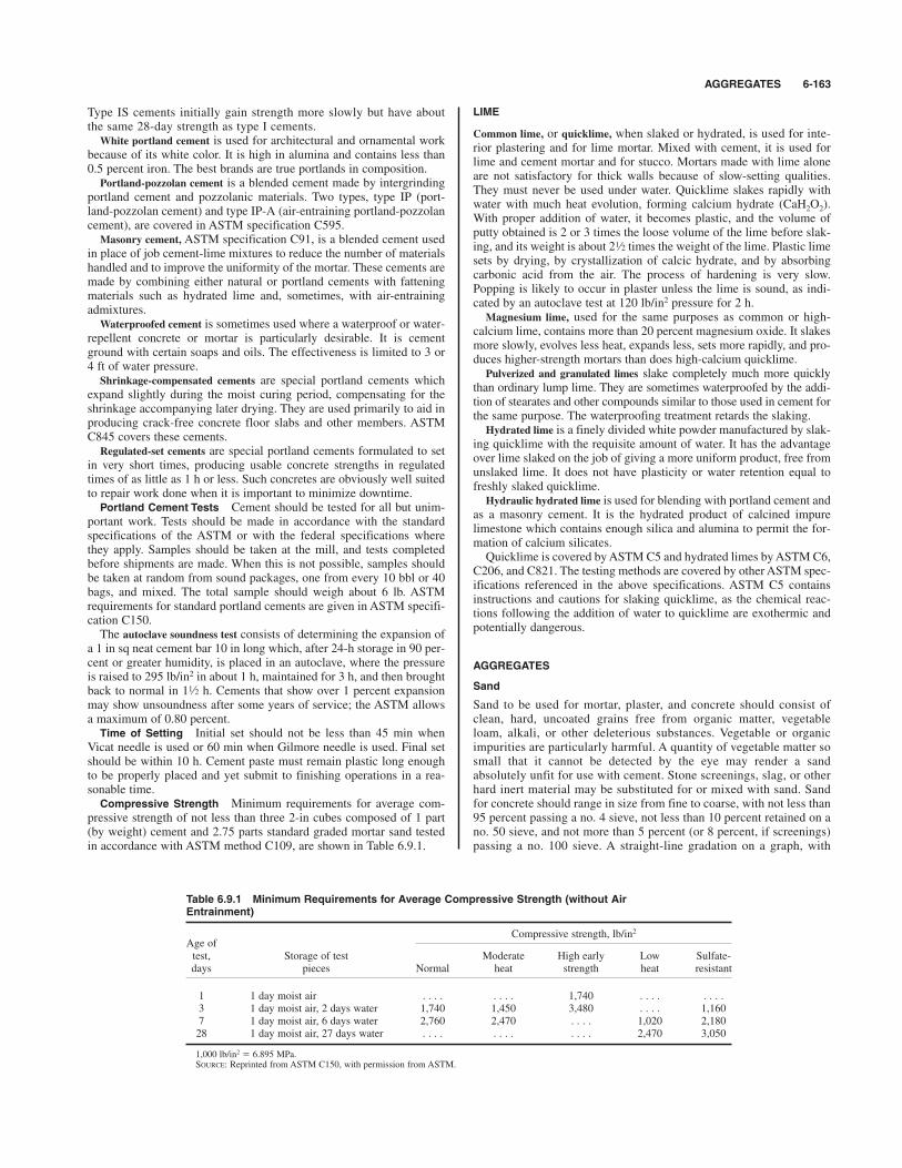
AGGREGATES 6-163
Type IS cements initially gain strength more slowly but have aboutthe same 28-day strength as type I cements.White portland cement is used for architectural and ornamental work
because of its white color. It is high in alumina and contains less than0.5 percent iron. The best brands are true portlands in composition.Portland-pozzolan cement is a blended cement made by intergrinding
portland cement and pozzolanic materials. Two types, type IP (port-land-pozzolan cement) and type IP-A (air-entraining portland-pozzolancement), are covered in ASTM specification C595.Masonry cement, ASTM specification C91, is a blended cement used
in place of job cement-lime mixtures to reduce the number of materialshandled and to improve the uniformity of the mortar. These cements aremade by combining either natural or portland cements with fatteningmaterials such as hydrated lime and, sometimes, with air-entrainingadmixtures.Waterproofed cement is sometimes used where a waterproof or water-
repellent concrete or mortar is particularly desirable. It is cementground with certain soaps and oils. The effectiveness is limited to 3 or4 ft of water pressure.Shrinkage-compensated cements are special portland cements which
expand slightly during the moist curing period, compensating for theshrinkage accompanying later drying. They are used primarily to aid inproducing crack-free concrete floor slabs and other members. ASTMC845 covers these cements.Regulated-set cements are special portland cements formulated to set
in very short times, producing usable concrete strengths in regulatedtimes of as little as 1 h or less. Such concretes are obviously well suitedto repair work done when it is important to minimize downtime.
Portland Cement Tests Cement should be tested for all but unim-portant work. Tests should be made in accordance with the standardspecifications of the ASTM or with the federal specifications wherethey apply. Samples should be taken at the mill, and tests completedbefore shipments are made. When this is not possible, samples shouldbe taken at random from sound packages, one from every 10 bbl or 40bags, and mixed. The total sample should weigh about 6 lb. ASTMrequirements for standard portland cements are given in ASTM specifi-cation C150.The autoclave soundness test consists of determining the expansion of
a 1 in sq neat cement bar 10 in long which, after 24-h storage in 90 per-cent or greater humidity, is placed in an autoclave, where the pressureis raised to 295 lb/in2 in about 1 h, maintained for 3 h, and then broughtback to normal in 1 h. Cements that show over 1 percent expansionmay show unsoundness after some years of service; the ASTM allowsa maximum of 0.80 percent.
Time of Setting Initial set should not be less than 45 min whenVicat needle is used or 60 min when Gilmore needle is used. Final setshould be within 10 h. Cement paste must remain plastic long enoughto be properly placed and yet submit to finishing operations in a rea-sonable time.
Compressive Strength Minimum requirements for average com-pressive strength of not less than three 2-in cubes composed of 1 part(by weight) cement and 2.75 parts standard graded mortar sand testedin accordance with ASTM method C109, are shown in Table 6.9.1.
1⁄2
LIME
Common lime, or quicklime, when slaked or hydrated, is used for inte-rior plastering and for lime mortar. Mixed with cement, it is used forlime and cement mortar and for stucco. Mortars made with lime aloneare not satisfactory for thick walls because of slow-setting qualities.They must never be used under water. Quicklime slakes rapidly withwater with much heat evolution, forming calcium hydrate (CaH2O2).With proper addition of water, it becomes plastic, and the volume ofputty obtained is 2 or 3 times the loose volume of the lime before slak-ing, and its weight is about 2 times the weight of the lime. Plastic limesets by drying, by crystallization of calcic hydrate, and by absorbingcarbonic acid from the air. The process of hardening is very slow.Popping is likely to occur in plaster unless the lime is sound, as indi-cated by an autoclave test at 120 lb/in2 pressure for 2 h.Magnesium lime, used for the same purposes as common or high-
calcium lime, contains more than 20 percent magnesium oxide. It slakesmore slowly, evolves less heat, expands less, sets more rapidly, and pro-duces higher-strength mortars than does high-calcium quicklime.Pulverized and granulated limes slake completely much more quickly
than ordinary lump lime. They are sometimes waterproofed by the addi-tion of stearates and other compounds similar to those used in cement forthe same purpose. The waterproofing treatment retards the slaking.Hydrated lime is a finely divided white powder manufactured by slak-
ing quicklime with the requisite amount of water. It has the advantageover lime slaked on the job of giving a more uniform product, free fromunslaked lime. It does not have plasticity or water retention equal tofreshly slaked quicklime.Hydraulic hydrated lime is used for blending with portland cement and
as a masonry cement. It is the hydrated product of calcined impurelimestone which contains enough silica and alumina to permit the for-mation of calcium silicates.Quicklime is covered by ASTM C5 and hydrated limes by ASTM C6,
C206, and C821. The testing methods are covered by other ASTM spec-ifications referenced in the above specifications. ASTM C5 containsinstructions and cautions for slaking quicklime, as the chemical reac-tions following the addition of water to quicklime are exothermic andpotentially dangerous.
AGGREGATES
Sand
Sand to be used for mortar, plaster, and concrete should consist ofclean, hard, uncoated grains free from organic matter, vegetableloam, alkali, or other deleterious substances. Vegetable or organicimpurities are particularly harmful. A quantity of vegetable matter sosmall that it cannot be detected by the eye may render a sandabsolutely unfit for use with cement. Stone screenings, slag, or otherhard inert material may be substituted for or mixed with sand. Sandfor concrete should range in size from fine to coarse, with not less than95 percent passing a no. 4 sieve, not less than 10 percent retained on ano. 50 sieve, and not more than 5 percent (or 8 percent, if screenings)passing a no. 100 sieve. A straight-line gradation on a graph, with
1⁄2
Table 6.9.1 Minimum Requirements for Average Compressive Strength (without AirEntrainment)
Age ofCompressive strength, lb/in2
test, Storage of test Moderate High early Low Sulfate-days pieces Normal heat strength heat resistant
1 1 day moist air . . . . . . . . 1,740 . . . . . . . .3 1 day moist air, 2 days water 1,740 1,450 3,480 . . . . 1,1607 1 day moist air, 6 days water 2,760 2,470 . . . . 1,020 2,18028 1 day moist air, 27 days water . . . . . . . . . . . . 2,470 3,050
1,000 lb/in2 # 6.895 MPa.SOURCE: Reprinted from ASTM C150, with permission from ASTM.
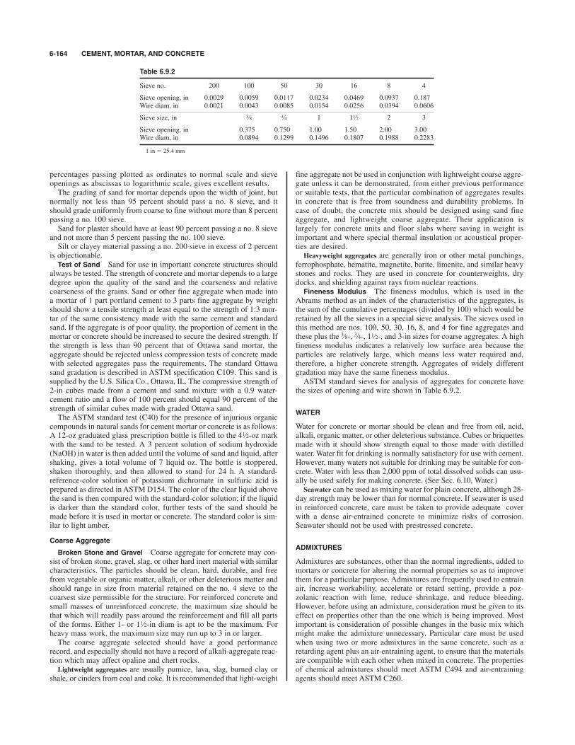
percentages passing plotted as ordinates to normal scale and sieveopenings as abscissas to logarithmic scale, gives excellent results.The grading of sand for mortar depends upon the width of joint, but
normally not less than 95 percent should pass a no. 8 sieve, and itshould grade uniformly from coarse to fine without more than 8 percentpassing a no. 100 sieve.Sand for plaster should have at least 90 percent passing a no. 8 sieve
and not more than 5 percent passing the no. 100 sieve.Silt or clayey material passing a no. 200 sieve in excess of 2 percent
is objectionable.Test of Sand Sand for use in important concrete structures should
always be tested. The strength of concrete and mortar depends to a largedegree upon the quality of the sand and the coarseness and relativecoarseness of the grains. Sand or other fine aggregate when made intoa mortar of 1 part portland cement to 3 parts fine aggregate by weightshould show a tensile strength at least equal to the strength of 1:3 mor-tar of the same consistency made with the same cement and standardsand. If the aggregate is of poor quality, the proportion of cement in themortar or concrete should be increased to secure the desired strength. Ifthe strength is less than 90 percent that of Ottawa sand mortar, theaggregate should be rejected unless compression tests of concrete madewith selected aggregates pass the requirements. The standard Ottawasand gradation is described in ASTM specification C109. This sand issupplied by the U.S. Silica Co., Ottawa, IL. The compressive strength of2-in cubes made from a cement and sand mixture with a 0.9 water-cement ratio and a flow of 100 percent should equal 90 percent of thestrength of similar cubes made with graded Ottawa sand.The ASTM standard test (C40) for the presence of injurious organic
compounds in natural sands for cement mortar or concrete is as follows:A 12-oz graduated glass prescription bottle is filled to the 4 -oz markwith the sand to be tested. A 3 percent solution of sodium hydroxide(NaOH) in water is then added until the volume of sand and liquid, aftershaking, gives a total volume of 7 liquid oz. The bottle is stoppered,shaken thoroughly, and then allowed to stand for 24 h. A standard-reference-color solution of potassium dichromate in sulfuric acid isprepared as directed in ASTM D154. The color of the clear liquid abovethe sand is then compared with the standard-color solution; if the liquidis darker than the standard color, further tests of the sand should bemade before it is used in mortar or concrete. The standard color is sim-ilar to light amber.
Coarse Aggregate
Broken Stone and Gravel Coarse aggregate for concrete may con-sist of broken stone, gravel, slag, or other hard inert material with similarcharacteristics. The particles should be clean, hard, durable, and freefrom vegetable or organic matter, alkali, or other deleterious matter andshould range in size from material retained on the no. 4 sieve to thecoarsest size permissible for the structure. For reinforced concrete andsmall masses of unreinforced concrete, the maximum size should bethat which will readily pass around the reinforcement and fill all partsof the forms. Either 1- or 1 -in diam is apt to be the maximum. Forheavy mass work, the maximum size may run up to 3 in or larger.The coarse aggregate selected should have a good performance
record, and especially should not have a record of alkali-aggregate reac-tion which may affect opaline and chert rocks.Lightweight aggregates are usually pumice, lava, slag, burned clay or
shale, or cinders from coal and coke. It is recommended that light-weight
1⁄2
1⁄2
fine aggregate not be used in conjunction with lightweight coarse aggre-gate unless it can be demonstrated, from either previous performanceor suitable tests, that the particular combination of aggregates resultsin concrete that is free from soundness and durability problems. Incase of doubt, the concrete mix should be designed using sand fineaggregate, and lightweight coarse aggregate. Their application islargely for concrete units and floor slabs where saving in weight isimportant and where special thermal insulation or acoustical proper-ties are desired.Heavyweight aggregates are generally iron or other metal punchings,
ferrophosphate, hematite, magnetite, barite, limenite, and similar heavystones and rocks. They are used in concrete for counterweights, drydocks, and shielding against rays from nuclear reactions.
Fineness Modulus The fineness modulus, which is used in theAbrams method as an index of the characteristics of the aggregates, isthe sum of the cumulative percentages (divided by 100) which would beretained by all the sieves in a special sieve analysis. The sieves used inthis method are nos. 100, 50, 30, 16, 8, and 4 for fine aggregates andthese plus the -, -, 1 -, and 3-in sizes for coarse aggregates. A highfineness modulus indicates a relatively low surface area because theparticles are relatively large, which means less water required and,therefore, a higher concrete strength. Aggregates of widely differentgradation may have the same fineness modulus.ASTM standard sieves for analysis of aggregates for concrete have
the sizes of opening and wire shown in Table 6.9.2.
WATER
Water for concrete or mortar should be clean and free from oil, acid,alkali, organic matter, or other deleterious substance. Cubes or briquettesmade with it should show strength equal to those made with distilledwater. Water fit for drinking is normally satisfactory for use with cement.However, many waters not suitable for drinking may be suitable for con-crete. Water with less than 2,000 ppm of total dissolved solids can usu-ally be used safely for making concrete. (See Sec. 6.10, Water.)Seawater can be used as mixing water for plain concrete, although 28-
day strength may be lower than for normal concrete. If seawater is usedin reinforced concrete, care must be taken to provide adequate coverwith a dense air-entrained concrete to minimize risks of corrosion.Seawater should not be used with prestressed concrete.
ADMIXTURES
Admixtures are substances, other than the normal ingredients, added tomortars or concrete for altering the normal properties so as to improvethem for a particular purpose. Admixtures are frequently used to entrainair, increase workability, accelerate or retard setting, provide a poz-zolanic reaction with lime, reduce shrinkage, and reduce bleeding.However, before using an admixture, consideration must be given to itseffect on properties other than the one which is being improved. Mostimportant is consideration of possible changes in the basic mix whichmight make the admixture unnecessary. Particular care must be usedwhen using two or more admixtures in the same concrete, such as aretarding agent plus an air-entraining agent, to ensure that the materialsare compatible with each other when mixed in concrete. The propertiesof chemical admixtures should meet ASTM C494 and air-entrainingagents should meet ASTM C260.
1⁄23⁄43⁄8
6-164 CEMENT, MORTAR, AND CONCRETE
Table 6.9.2
Sieve no. 200 100 50 30 16 8 4
Sieve opening, in 0.0029 0.0059 0.0117 0.0234 0.0469 0.0937 0.187Wire diam, in 0.0021 0.0043 0.0085 0.0154 0.0256 0.0394 0.0606
Sieve size, in 1 1 2 3
Sieve opening, in 0.375 0.750 1.00 1.50 2.00 3.00Wire diam, in 0.0894 0.1299 0.1496 0.1807 0.1988 0.2283
1 in # 25.4 mm
1⁄23⁄43⁄8

MORTARS 6-165
Air-entraining agents constitute one of the most important groups ofadmixtures. They entrain air in small, closely spaced, separated bubblesin the concrete, greatly improving resistance to freezing and thawingand to deicing agents.Accelerators are used to decrease the setting time and increase early
strength. They permit shorter curing periods, earlier form removal, andplacing at lower temperatures. Calcium chloride is the most frequentlyused accelerator and can be used in amounts up to 2 percent of theweight of the cement, but must never be used with prestressed concrete.Retarders increase the setting time. They are particularly useful in hot
weather and in grouting operations.Water reducers are used to increase the workability of concrete with-
out an accompanying increase in the water content. The most recentdevelopment is the use of high-range water reducers, or superplasticiz-ers, which are polymer liquid materials added to the concrete in themixer. These materials lead to spectacular temporary increases inslump for a given water content, and may be used to obtain severaldifferent results. A normal mix can be transformed into a “flowing”concrete which will practically level itself. Or the addition of the super-plasticizer can allow the mix to be redesigned for the same consistencyat the time of mixing, but considerably less water will be required andconsequently a higher concrete strength can be reached without addingcement, or the same strength can be reached with a lower cementcontent.Fly ash from coal-burning power plants can be added to concrete
mixes to achieve several effects. The very fine material tends to act as alubricant to the wet concrete, and thus may be added primarily toincrease the workability. Fly ash also enters the chemical reactionsinvolved in the setting of concrete and leads to higher strengths. Fly ashis often used in mass concrete such as dams as a replacement for part ofthe cement, in order to save some material costs, to reduce the rate atwhich the hydration produces heat, and to increase the long-termstrength gain potential of the concrete. Fly ash is a pozzolan, and shouldmeet requirements of ASTM C618. Free carbon from incomplete com-bustion must be strictly limited.
Silica Fume Silica fume, also called condensed silica fume ormicrosilica, is another pozzolan which may be added to concrete as asupplement or partial replacement to the cement. This material reactswith the lime in the cement and helps lead to very high-strength, low-permeability concrete. The silica-lime reaction can occur very quickly,and retarders are often necessary in concretes containing silica fume.Silica fume should meet the requirements of ASTM C 1240. Concretescontaining silica fume tend to be quite dark gray compared with ordi-nary concrete mixes, and concretes containing fly ash tend to be lighterthan the usual concrete gray.
Ground Granulated Blast-Furnace Slag Ground granulated blast-furnace slag has been used in Europe as a supplement to or partialreplacement for portland cement for several decades but has become
available in North America relatively recently. Concretes made withthis material tend to develop very low permeabilities, which improvesdurability by retarding oxygen and chloride penetration, which in turnprotects the reinforcement from corrosion for longer periods. Chloridesources include both deicing chemicals and seawater, and these concreteshave been successfully used to resist both these severe environments.They are also sulfate-resistant, which is important in those geographicareas which have sulfate-bearing groundwater. Ground granulated blast-furnace slag should meet the requirements of ASTM C 989.Other admixtures may be classed as gas-forming agents, pozzolanic
materials, curing aids, water-repelling agents, and coloring agents.
MORTARS
Properties desirable in a mortar include (1) good plasticity or workabil-ity, (2) low volume change or volume change of the same character asthe units bonded, (3) low absorption, (4) low solubility and thus free-dom from efflorescence, (5) good strength in bond and ample strengthto withstand applied loads, (6) high resistance to weathering.
Mortar Types There are several different types of mortar which aresuitable for masonry construction of different kinds, uses, and exposureconditions. The BOCA National Building Code lists several mortartypes, and their permitted uses are given in Table 6.9.3. The makeup ofthese mortars is specified in terms of volumes of materials, as listed inTable 6.9.4, from ASTM C 270. There is considerable leeway given for
Table 6.9.3 Masonry and Mortar Types
Type of mortarType of masonry permitted
Masonry in contact with earth M or SGrouted and filled cell masonry M or SMasonry above grade or interior masonryPiers of solid units M, S, or NPiers of hollow units M or SWalls of solid units M, S, N, or OWalls of hollow units M, S, or NCavity walls and masonry bonded hollow wallsDesign wind pressure exceeds 20 lb/ft2 M or SDesign wind pressure 20 lb/ft2 or less M, S, or N
Glass block masonry S or NNon-load-bearing partitions and fireproofing M, S, N, O, or gypsumFirebrick Refractory air-setting
mortarLinings of existing masonry, above or below grade M or SMasonry other than above M, S, or N
1 lb/ft2 # 47.9 Pa.SOURCE: BOCA National Building Code.
Table 6.9.4 Mortar Proportions Specification Requirements (Parts by Volume)
Hydrated limeor
Mortar Portland Masonrylime putty
type cement cement Min Max Damp loose aggregate
M 11 1
S 1 Not less than 2 and not more than1 3 times the sum of the volumes
of the cements and lime used
N 1 11
O 11 1 2
SOURCE: ASTM C 270.
1⁄21⁄4
1⁄41⁄2
1⁄2
1⁄41⁄21⁄4
1⁄4

the proportions, and the materials are mixed with water to the consis-tency desired by the mason. The portland cement, masonry cement, andlime may be purchased separately or blended, and for small jobs a drymix mortar containing everything except the water may be purchased inbags. The hydrated lime tends to give the fresh mortar plasticity, orstickiness, which is necessary for the proper bedding of the masonry orconcrete units being laid.Additional mortar types may be used for reinforced masonry, in
which steel bars are used to increase the strength in the same way thatconcrete is reinforced. Other mortars may be used for filling the cavi-ties in concrete block construction, or concrete masonry unit construc-tion, and this mortar may be referred to as grout.Design procedures and requirements for concrete and clay masonry
are contained in ACI 530/TMS 402/ASCE 5. Unreinforced masonrycannot be relied on to resist tension stresses. Compressive stressespermitted under the empirical design rules vary widely, depending onthe strength and type of masonry unit. The highest stress permitted is350 lb/in2 for high-strength solid bricks, while the lowest is 60 lb/in2
for the lowest-strength hollow-concrete blocks, where the stresses arecomputed on the gross area and the units are laid with type M or Smortar. Type N mortar leads to stresses which are 10 to 15 percent lower.
Mortars for Plastering and Stucco Interior plastering is much lesscommon than it was in the past because of the use of gypsum boardproducts for walls, but is done in various instances. Common lime plas-ter consists of hydrated lime (usually purchased in prepared, baggedform), clean coarse sand, and hair or fiber. The plastering is normallydone in two or three layers, with the base coats containing about equalvolumes of lime and sand, plus hair or fiber, and the final layer con-taining less sand. In three-layer work, the first layer is the scratch coat,the second the brown coat, and the last the white or skim coat. Thescratch coat is applied directly to either a masonry wall or the lath in aframe wall. Skim coat is a finish coat composed of lime putty and fine white sand.
It is placed in two layers and troweled to a hard finish. Gaged skim coatis skimming mixed with a certain amount of plaster of paris, whichmakes it a hard finish. Hard finish consists of 1 part lime putty to 1 or2 parts plaster of paris.Keene’s cement, which is an anhydrous calcined gypsum with an
accelerator, is much used as a hard-finish plaster.Gypsum plaster (ASTM C28) lacks the plasticity and sand-carrying
capacity of lime plaster but is widely used because of its more rapidhardening and drying and because of the uniformity obtainable as theresult of its being put up in bags ready-mixed for use.Gypsum ready-mixed plaster should contain not more than 3 ft3 of
mineral aggregate per 100 lb of calcined gypsum plaster, to which maybe added fiber and material to control setting time and workability.Gypsum neat plaster used in place of sanded plaster for second coatshould contain at least 66 percent CaSO4 : H2O; the remainder may befiber and retarders. Calcined gypsum for finishing coat may be white orgray. If it contains no retarder, it should set between 20 and 40 min; ifretarded, it should set between 40 min and 6 h.Cement plaster is used where a very hard or strong plaster is required,
e.g., for thin metal-lath partitions or as a fire protection. It shouldcontain not more than 2 parts sand, by dry and loose volume, to 1 partportland cement. Lime putty or hydrated lime is added up to 15 per-cent by volume of the cement.Under moisture conditions where the plaster will not dry rapidly,
curing at temperatures above 60 and below 90*F is absolutely necessaryif cracking is to be avoided.
Stucco Stucco is used for exterior plastering and is applied to brickor stone or is plastered onto wood or metal lath. For covering woodenbuildings, the stucco is plastered either on wood lath or on metal lath inthree coats, using mortar similar to that for brick or stone. Concrete innorthern climates exposed to frost should never be plastered but shouldbe finished by rubbing down with carborundum brick or similar toolwhen the surface is comparatively green. It may also be tooled in vari-ous ways. Whenever stucco is used, extreme care must be taken to geta good bond to the supporting surface. While stucco has traditionallybeen applied with a trowel, it can also be applied pneumatically. Similar
1⁄2
material used for lining metal pipes can be applied with a centrifugaldevice which “slings” the material onto the pipe wall.For three-coat work on masonry or wood lath, the first or scratch coat
should average in thick outside the lath or surface of the brick. Thethickness of the second coat should be to in, while the finish coatshould be thin, i.e., in or not more than in. The second coat shouldgenerally be applied 24 h after the first or scratch coat. The finish coatshould not be applied in less than 1 week after the second coat.Proportions of mix for all coats may be part hydrated lime, 1 partportland cement, 3 parts fairly coarse sand, measured by volume.Stucco work should not be put on in freezing weather and must be keptmoist for at least 7 days after application of the mortar. Mineral colors for stucco, if used, should be of such composition that
they will not be affected by cement, lime, or the weather. The bestmethod is to use colored sands when possible. The most satisfactoryresults with colored mortar are obtained by using white portlandcement. Prepared patented stuccos which are combinations of cement,sand, plasticizers, waterproofing agents, and pigment are widely used.
CONCRETE
Concrete is made by mixing cement and an aggregate composed of hardinert particles of varying size, such as a combination of sand or bro-kenstone screenings, with gravel, broken stone, lightweight aggregate,or other material. Portland cement should always be used for reinforcedconcrete, for mass concrete subjected to stress, and for all concrete laidunder water.
Proportioning Concrete Compressive strength is generally acceptedas the principal measure of the quality of concrete, and although this isnot entirely true, there is an approximate relation between compressivestrength and the other mechanical properties. Methods of proportioninggenerally aim to give concrete of a predetermined compressive strength.The concrete mixture is proportioned or designed for a particular
condition in various ways: (1) arbitrary selection based on experienceand common practice, such as 1 part cement, 2 parts sand, 4 parts stone(written 1: 2 : 4); (2) proportioning on the basis of the water/cementratio, either assumed from experience or determined by trial mixtureswith the given materials and conditions; (3) combining materials on thebasis of either the voids in the aggregates or mechanical-analysis curvesso as to obtain the least voids and thus concrete of the maximum densityfor a given cement content.Concrete mixes for small jobs can generally be determined by con-
sultation with a ready-mixed concrete supplier, on the basis of the sup-plier’s experience. If this information is not available, the mixesrecommended by ACI Committee 211 and reproduced in Table 6.9.5can be used as long as the required compressive strength is not higherthan perhaps 3,500 lb/in2. It is important that the mix be kept as dry ascan be satisfactorily compacted, by vibration, into the form work sinceexcess water reduces the eventual compressive strength. And the airentrainment is important for concretes which will be exposed to freeze-thaw cycles after curing.For larger jobs and in all cases where high compressive strength is
necessary, the mix must be designed on a more thorough basis. Again, local suppliers of ready-mixed concrete may have records which will beof considerable help. The concrete mix has several contradictoryrequirements placed on it, so the final product represents a compromise.The hardened concrete must be strong enough for its intended use, itmust be durable enough for its expected exposure conditions, and thefreshly mixed concrete must be workable enough to be placed and com-pacted in the forms.For a given aggregate type and size, the strength is controlled pri-
marily by the water/cement ratio, with a decrease in water content, rel-ative to cement, leading to an increase in strength, as long as theconcrete remains workable enough to be placed. The durability is con-trolled by the water/cement ratio and the air content, assuming a suit-able aggregate for the exposure condition. Table 6.9.6, from ACICommittee 211, gives the maximum water/cement ratios which shouldbe used in severe exposure conditions, and Table 6.9.7 gives thewater/cement ratios required for various concrete strengths.
1⁄5
1⁄41⁄8
1⁄23⁄8
1⁄4
6-166 CEMENT, MORTAR, AND CONCRETE
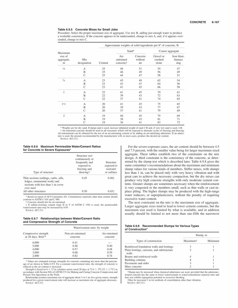
CONCRETE 6-167
For the severe-exposure cases, the air content should be between 4.5and 7.5 percent, with the smaller value being for larger maximum sizedaggregate. These tables establish two of the constraints on the mixdesign. A third constraint is the consistency of the concrete, as deter-mined by the slump test which is described later. Table 6.9.8 gives thesame committee’s recommendations about the maximum and minimumslump values for various kinds of members. Stiffer mixes, with slumpsless than 1 in, can be placed only with very heavy vibration and withgreat care to achieve the necessary compaction, but the dry mixes canproduce very high concrete strengths with only moderate cement con-tents. Greater slumps are sometimes necessary when the reinforcementis very congested or the members small, such as thin walls or cast-in-place piling. The higher slumps may be produced with the high-rangewater reducers, or superplasticizers, without the penalty of requiringexcessive water content.The next constraint on the mix is the maximum size of aggregate.
Larger aggregate sizes tend to lead to lower cement contents, but themaximum size used is limited by what is available, and in additionusually should be limited to not more than one-fifth the narrowest
Table 6.9.5 Concrete Mixes for Small JobsProcedure: Select the proper maximum size of aggregate. Use mix B, adding just enough water to produce a workable consistency. If the concrete appears to be undersanded, change to mix A, and, if it appears over-sanded, change to mix C.
Approximate weights of solid ingredients per ft3 of concrete, lb
MaximumSand* Coarse aggregate
size of Air- Concrete Gravel or Iron blast-aggregate, Mix entrained without crushed furnace
in designation Cement concrete† air stone slag
A 25 48 51 54 47B 25 46 49 56 49C 25 44 47 58 51
A 23 45 49 62 54B 23 43 47 64 56C 23 41 45 66 58
1 A 22 41 45 70 61B 22 39 43 72 63C 22 37 41 74 65
1 A 20 41 45 75 65B 20 39 43 77 67C 20 37 41 79 69
2 A 19 40 45 79 69B 19 38 43 81 71C 19 36 41 83 72
* Weights are for dry sand. If damp sand is used, increase tabulated weight of sand 2 lb and, if very wet sand is used, 4 lb.† Air-entrained concrete should be used in all stxuctures which will be exposed to alternate cycles of freezing and thawing.
Air-entrainment can be obtained by the use of an air-entraining cement or by adding an air-entraining admixture. If an admix-ture is used, the amount recommended by the manufacturer will, in most cases, produce the desired air content.SOURCE: ACI 211.
1⁄2
3⁄4
1⁄8
Table 6.9.6 Maximum Permissible Water/Cement Ratios for Concrete in Severe Exposures*
Structure wetcontinuously orfrequently and Structureexposed to exposed tofreezing and seawater
Type of structure thawing† or sulfates
Thin sections (railings, curbs, sills, 0.45 0.40‡ledges, ornamental work) and sections with less than 1-in coverover steelAll other structures 0.50 0.45‡
* Based on report of ACI Committee 201. Cementitious materials other than cement shouldconform to ASTM C 618 and C 989.† Concrete should also be air-entrained.‡ If sulfate-resisting cement (type II or V of ASTM C 150) is used, the permissiable
water/cement ratio may be increased by 0.05.SOURCE: ACI 211.
Table 6.9.7 Relationships between Water/Cement Ratio and Compressive Strength of Concrete
Water/cement ratio, by weight
Compressive strength Non-air-entrained Air-entrainedat 28 days, lb/in2* concrete concrete
6,000 0.41 —5,000 0.48 0.404,000 0.57 0.483,000 0.68 0.592,000 0.82 0.74
* Values are estimated average strengths for concrete containing not more than the percent-age of air shown in Table 6.9.9. For a constant water/cement ratio, the strength of concrete isreduced as the air content is increased.Strength is based on 6 % 12 in cylinders moist-cured 28 days at 73.4 , 3*F (23 , 1.7*C) in
accordance with Section 9(b) of ASTM C31 for Making and Curing Concrete Compression andFlexure Test Specimens in the Field.Relationship assumes maximum size of aggregate about to 1 in; for a given source, strength
produced for a given water/cement ratio will increase as maximum size of aggregate decreases.SOURCE: ACI 211.
3⁄4
Table 6.9.8 Recommended Slumps for Various Types of Construction*
Slump, in
Types of construction Maximum† Minimum
Reinforced foundation walls and footings 3 1Plain footings, caissons, and substructure 3 1wallsBeams and reinforced walls 4 1Building columns 4 1Pavements and slabs 3 1Mass concrete 2 1
*Slump may be increased when chemical admixtures are used, provided that the admixture-treated concrete has the same or lower water/cement or water/cementitious material ratio anddoes not exhibit segregation potential or excessive bleeding.†May be increased 1 in for methods of consolidation other than vibration.SOURCE: ACI 211.

width between forms, one-third the thickness of slabs, three-fourthsthe minimum clear spacing between reinforcing steel. Extremelystrong concretes will require smaller rather than larger maximumaggregate sizes. Once the maximum-size stone has been selected, thewater content to produce the desired slump can be estimated fromTable 6.9.9, and once the water content has been determined, thecement content is determined from the required water/cement ratiodetermined earlier. The volume of coarse aggregate is then deter-mined from Table 6.9.10, and when the fraction is multiplied by thedry rodded unit weight, the weight of coarse aggregate per unit vol-ume of concrete can be found. The weight of sand needed to make a cubic yard of concrete can then
be estimated by adding up the weights of materials determined so far,and subtracting from the expected weight of a cubic yard of concrete,which might be estimated at 3,900 lb for an air-entrained concrete and4,000 lb for a mix without air. This weight should be the surface-drysaturated weight, with a correction made for the moisture content of thesand by increasing the weight of sand and decreasing the amount of mixwater. Table 6.9.11 gives the expected ranges of water content of fineand coarse aggregates. Concretes with small-maximum-size aggregates
6-168 CEMENT, MORTAR, AND CONCRETE
Table 6.9.9 Approximate Mixing Water and Air Content Requirements for DifferentSlumps and Nominal Maximum Sizes of Aggregates
Water, lb/yd3 of concrete for indicated nominal maximum sizes of aggregate
Slump, in ina ina ina 1 ina 1 ina 2 ina,b 3 inb,c 6 inb,c
Non-air-entrained concrete
1–2 350 335 315 300 275 260 220 1903–4 385 365 340 325 300 285 245 2106–7 410 385 360 340 315 300 270 —Approximate amount of 3 2.5 2 1.5 1 0.5 0.3 0.2entrapped air in non-air-entrained concrete, %
Air-entrained concrete
1–2 305 295 280 270 250 240 205 1803–4 340 325 305 295 275 265 225 2006–7 365 345 325 310 290 280 260 —Recommended averaged
total air content,percent for level ofexposure:Mild exposure 4.5 4.0 3.5 3.0 2.5 2.0 1.5e,g 1.0e,g
Moderate exposure 6.0 5.5 5.0 4.5 4.5 4.0 3.5e,g 3.0e,g
Extreme exposureg 7.5 7.0 6.0 6.0 5.5 5.0 4.5e,g 4.0e,g
a The quantities of mixing water given for air-entrained concrete are based on typical total air content requirements as shownfor moderate exposure in the table. These quantities of mixing water are for computing cement contents for trial batches at 68 to778F (20 to 258C). They are maximum for reasonably well-shaped angular aggregates graded within limits of accepted specifi-cations. Rounded aggregates will generally require 30 lb less water for non-air-entrained and 25 lb less for air-entrained con-cretes. The use of water-reducing chemical admixtures, ASTM C 494, may also reduce mixing water by 5 percent or more. Thevolume of liquid admixtures is included as part of the total volume of mixing water. Slump values of more than 7 in are onlyobtained through the use of water-reducing chemical admixtures; they are for concrete containing nominal maximum size aggre-gate not larger than 1 in.
b The slump values for concrete containing aggregate larger than 1 in are based on slump tests made after removal of par-ticles larger than 1 in by wet-screening.
c These quantities of mixing water are for use in computing cement factors for trial batches when 3 in or 6 in nominal maxi-mum size aggregate is used. They are average for reasonably well-shaped coarse aggregates, well-graded from coarse to fine.
d Additional recommendations for air content and necessary tolerances on air content for control in the field are given in anumber of ACI documents, including ACI 201, 345, 318, 301, and 302. ASTM C 94 for ready-mixed concrete also gives air-content limits. The requirements in other documents may not always agree exactly so in proportioning concrete considerationmust be given to selecting an air content that will meet the needs of the job and also meet the applicable specifications.
e For concrete containing large aggregates which will be wet-screened over the 1 in sieve prior to testing for air content, thepercentage of air expected in the 1 in minus material should be as tabulated in the 1 in column. However, initial propor-tioning calculations should include the air content as a percent of the whole.
fWhen using large aggregate in low cement factor concrete, air entrainment need not be detrimental to strength. In most casesmixing water requirement is reduced sufficiently to improve the water/cement ratio and to thus compensate for the strengthreducing effect of entrained air concrete. Generally, therefore, for these large maximum sizes of aggregate, air contents recom-mended for extreme exposure should be considered even though there may be little or no exposure to moisture and freezing.
g These values are based on the criteria that 9 percent air is needed in the mortar phase of the concrete. If the mortar volumewill be substantially different from that determined in this recommended practice, it may be desirable to calculate the neededair content by taking 9 percent of the actual mortar volume.SOURCE: ACI 211.
1⁄21⁄2
1⁄2
1⁄2
1⁄2
1⁄23⁄41⁄23⁄8
Table 6.9.10 Volume of Coarse Aggregate per Unit Volumeof Concrete
Volume of dry-rodded coarse aggregate*
Maximum sizeper unit volume of concrete different
of aggregate,fineness moduli of sand
in 2.40 2.60 2.80 3.00
0.50 0.48 0.46 0.440.59 0.57 0.55 0.530.66 0.64 0.62 0.60
1 0.71 0.69 0.67 0.651 0.75 0.73 0.71 0.692 0.78 0.76 0.74 0.723 0.82 0.80 0.78 0.766 0.87 0.85 0.83 0.81
aVolumes are based on aggregates in oven-dry-rodded condition as described in ASTM C 29for Unit Weight of Aggregate.These volumes are selected from empirical relationships to produce concrete with a degree
of workability suitable for usual reinforced construction. For less workable concrete such asrequired for concrete pavement construction they may be increased about 10 percent.SOURCE: ACI 211.
1⁄2
3⁄4
1⁄2
3⁄8

CONCRETE 6-169
will be lighter than the values just cited, and concretes with aggregateslarger than 1 in will probably be heavier, and the kind of stone makingup the coarse aggregate will also make some difference.
be less than 1 min from the time all materials are in the mixer until thetime of discharge. Larger mixers require 25 percent increase in mixingtime per -yd3 increase in capacity. Increased mixing times up to 5 minincrease the workability and the strength of the concrete. Mixing shouldalways continue until the mass is homogeneous.Concrete mixers of the batch type give more uniform results; few con-
tinuous mixers are used. Batch mixers are either (1) rotating mixers,consisting of a revolving drum or a square box revolving about its diag-onal axis and usually provided with deflectors and blades to improvethe mixing; or (2) paddle mixers, consisting of a stationary box withmovable paddles which perform the mixing. Paddle mixers work betterwith relatively dry, high-sand, small-size aggregate mixtures and mor-tars and are less widely used than rotating mixers.Ready-mixed concrete is (1) proportioned and mixed at a central
plant (central-mixed concrete) and transported to the job in plaintrucks or agitator trucks, or (2) proportioned at a central plant andmixed in a mixer truck (truck-mixed concrete) equipped with watertanks, during transportation. Ready-mixed concrete is largely displac-ing job-mixed concrete in metropolitan areas. The truck agitators andmixers are essentially rotary mixers mounted on trucks. There is nodeleterious effect on the concrete if it is used within 1 h after thecement has been added to the aggregates. Specifications often state theminimum number of revolutions of the mixer drum following the lastaddition of materials.Materials for concrete are also centrally batched, particularly for
road construction, and transported to the site in batcher trucks withcompartments to keep aggregates separated from the cement. Thetruck discharges into the charging hopper of the job mixer. Road mix-ers sometimes are arranged in series—the first mixer partly mixes thematerials and discharges into a second mixer, which completes themixing.
Consistency of Concrete The consistency to be used dependsupon the character of the structure. The proportion of water in the mixis of vital importance. A very wet mixture of the same cement contentis much weaker than a dry or mushy mixture. Dry concrete can beemployed in dry locations for mass foundations provided that it is care-fully spread in layers not over 6 in thick and is thoroughly rammed.Medium, or quaking, concrete is adapted for ordinary mass-concreteuses, such as foundations, heavy walls, large arches, piers, and abut-ments. Mushy concrete is suitable as rubble concrete and reinforcedconcrete, for such applications as thin building walls, columns, floors,conduits, and tanks. A medium, or quaking, mixture has a tenacious,jellylike consistency which shakes on ramming; a mushy mixture willsettle to a level surface when dumped in a pile and will flow very slug-gishly into the forms or around the reinforcing bars; a dry mixture hasthe consistency of damp earth.The two methods in common use for measuring the consistency or
workability of concrete are the slump test and the flow test. In theslump test, which is the more widely used of the two, a form shaped asa frustum of a cone is filled with the concrete and immediatelyremoved. The slump is the subsidence of the mass below its heightwhen in the cone. The form has a base of 8-in diam, a top of 4-in diam,and a height of 12 in. It is filled in three 4-in layers of concrete, eachlayer being rodded by 25 strokes of a -in rod, 24 in long and bullet-pointed at the lower end.A test using the penetration of a half sphere, called the Kelly ball test,
is sometimes used for field control purposes. A 1-in penetration by theKelly ball corresponds to about 2 in of slump.Usual limitations on the consistency of concrete as measured by the
slump test are given in Table 6.9.8.The consistency of concrete has some relation to its workability, but
a lean mix may be unworkable with a given slump and a rich mix maybe very workable. Certain admixtures tend to lubricate the mix and,therefore, increase the workability at certain slumps. The slump at alltimes should be as small as possible consistent with the requirements ofhandling and placing. A slump over 7 in is usually accompanied by seg-regation and low strength of concrete, unless the high slump was pro-duced with the aid of a superplasticizer.
5⁄8
1⁄2
Table 6.9.11 Free MoistureContent
Dry Damp Wet
Gravel 0.2 1.0 2.0Sand 2.0 4.0 7.0
The mix properties just determined represent a starting point, and thefinal mix will usually be adjusted somewhat after trials have been con-ducted. Ideally, the trials should be done in a laboratory before the job-site concrete work starts, and the trial mixes should be evaluated forslump, tendency for segregation, ease with which the surface can be fin-ished (especially important for slabs), air content, actual unit weight,actual water requirements for the desired slump, and the compressivestrength of the concrete. It must be recognized that the various tablesare based on average conditions, and that a particular combination ofcement and aggregate may produce a concrete considerably stronger orweaker than expected from these values, and this can be true even whenall of the materials meet the appropriate limitations in the ASTM spec-ifications. Admixtures will also change the required mix proportions,and water reducers have the potential of allowing significant reductionsin cement content. The tables include values for very large aggregate,up to 6-in maximum size, but aggregate larger than 1 in will seldombe used in ordinary structures, and such concretes should be left tospecialists.It must also be recognized that consistent quality will be achieved
only when care is taken to ensure that the various materials are of con-sistently good quality. Variations in the size of the sand and coarseaggregate, dirty aggregate, improperly stored cement, very high or lowtemperatures, and carelessness in any of the batching and mixing oper-ations can reduce the uniformity and quality of the resulting concrete.The addition of extra water “to make it easier to place” is a too-commonfield error leading to poor concrete, since the extra water increases thewater/cement ratio, which reduces the strength and durability. Some ofthe tests used are described in the following paragraphs.The dry rodded weight is determined by filling a container, of a diam-
eter approximately equal to the depth, with the aggregate in three equallayers, each layer being rodded 25 times using a bullet-pointed rod in diam and 24 in long.Measurement of materials is usually done by weight. The bulking
effect of moisture, particularly on the fine aggregate, makes it difficultto keep proportions uniform when volume measurement is used. Wateris batched by volume or weight.
Mixing In order to get good concrete, the cement and aggregatesmust be thoroughly mixed so as to obtain a homogeneous mass and coatall particles with the cement paste. Mixing may be done either by handor by machine, although hand mixing is rare today.
Quality Control of Concrete Control methods include measuringmaterials by weight, allowing for the water content of the aggregates;careful limitation of the total water quantity to that designed; frequenttests of the aggregates and changing the proportions as found necessaryto maintain yield and workability; constant checks on the consistencyby the slump test, careful attention to the placing of steel and the fillingof forms; layout of the concrete distribution system so as to eliminatesegregation; check on the quality of the concrete as placed by means ofspecimens made from it as it is placed in the forms; and careful atten-tion to proper curing of the concrete. The field specimens of concreteare usually 6 in diam by 12 in high for aggregates up to 1 in max sizeand 8 by 16 in for 3-in aggregate. They are made by rodding the con-crete in three layers, each layer being rodded 25 times using a -indiam bullet-pointed rod 24 in long. Machine-mixed concrete is employed almost universally. The mix-
ing time for the usual batch mixer of 1 yd3 or less capacity should not
5⁄8
1⁄2
5⁄8
1⁄2

Forms for concrete should maintain the lines required and preventleakage of mortar. The pressure on forms is equivalent to that of a liquidwith the same density as the concrete, and of the depth placed within2 h. Dressed lumber or plywood is used for exposed surfaces, and roughlumber for unexposed areas. Wood or steel forms should be oiled beforeplacing concrete.Placement of concrete can be by dump-bottom buckets, concrete
pumps feeding into pipelines and hoses, buggies, chutes, or conveyorbelts. Buckets and buggies can handle drier mixes. Pumping will requirefairly rich mixes with moderately large slumps and maximum sizeaggregate not over about in (20 mm) unless it has been demonstratedthat the pump can handle harsher mixes. Pumping has become muchmore common in recent years, as pumps and mix design procedureshave developed. Pumps are often mounted on trucks that have extensiveboom arrangements, allowing placement over a large area. Chutesshould have a slope not less than 1 vertical to 2 horizontal; the use offlatter slopes encourages the use of excess water, leading to segregationand low strength. Conveyor belts have been used to place concrete inmass concrete dams, where very large quantities are required.Underwater concrete is placed by a dump-bottom bucket or a tremiepipe. Such concrete should have a cement content increase of 15 percentto allow for loss of cement during placement and/or an antiwashoutadmixture should be used.Compaction of concrete (working it into place) is accomplished by
tampers or vibrators. Vibrators are applied to the outside of the formsand to the surface or interior of the concrete; they should be used withcare to avoid producing segregation. The frequency of vibrators is usu-ally between 3,000 and 10,000 pulsations per minute.Curing of concrete is necessary to ensure proper hydration. Concrete
should be kept moist for a period of at least 7 days, and the temperatureshould not be allowed to fall below 50*F for at least 3 days. Sprayed-onmembrane curing compounds may be used to retain moisture. Specialprecautions must be taken in cold weather and in hot weather.
Weight of Concrete The following are average weights, lb/ft3, ofportland cement concrete:
Sand-cinder concrete 112 Limestone concrete 148
Burned-clay or shale concrete 105 Sandstone concrete 143
Gravel concrete 148 Traprock concrete 155
Watertightness Concrete can be made practically impervious towater by proper proportioning, mixing, and placing. Leakage throughconcrete walls is usually due to poor workmanship or occurs at thejoints between 2 days’ work or through cracks formed by contraction.New concrete can be bonded to old by wetting the old surface, plasteringit with neat cement, and then placing the concrete before the neat cementhas set. It is almost impossible to prevent contraction cracks entirely,although a sufficient amount of reinforcement may reduce their width soas to permit only seepage of water. For best results, a low-volume-changecement should be used with a concrete of a quaking consistency; theconcrete should be placed carefully so as to leave no visible stone pock-ets, and the entire structure should be made without joints and prefer-ably in one continuous operation. The best waterproofing agent is anadditional proportion of cement in the mix. The concrete should containnot less than 6 bags of cement per yd3.For maximum watertightness, mortar and concrete may require more
fine material than would be used for maximum strength. Gravel pro-duces a more watertight concrete than broken stone under similar con-ditions. Patented compounds are on the market for producing watertightconcrete, but under most conditions, equally good results can beobtained for less cost by increasing the percentage of cement in the mix.Membrane waterproofing, consisting of asphalt or tar with layers of feltor tarred paper, or plastic or rubber sheeting in extreme cases, is advis-able where it is expected that cracks will occur. Mortar troweled on veryhard may produce watertight work.Concrete to be placed through water should contain at least 7 bags of
cement per yd3 and should be of a quaking consistency.According to Fuller and Thompson (Trans. ASCE, 59, p. 67), water-
tightness increases (1) as the percentage of cement is increased and ina very much larger ratio; (2) as the maximum size of stone is increased,
3⁄4
provided the mixture is homogeneous; (3) materially with age; and (4)with thickness of the concrete, but in a much larger ratio. It decreasesuniformly with increase in pressure and rapidly with increase in thewater/cement ratio.
Air-Entrained Concrete The entrainment of from 3 to 6 percent byvolume of air in concrete by means of vinsol resin or other air-bubble-forming compounds has, under certain conditions, improved the resistanceof concrete in roads to frost and salt attack. The air entrainment increasesthe workability and reduces the compressive strength and the weight of theconcrete. As the amount of air entrainment produced by a given percent-age of vinsol resin varies with the cement, mixture, aggregates, slump,and mixing time, good results are dependent on very careful control.
Concrete for Masonry Units Mixtures for concrete masonry units,which are widely used for walls and partitions, employ aggregates of amaximum size of in and are proportioned either for casting or formachine manufacture. Cast units are made in steel or wooden forms andemploy concrete slumps of from 2 to 4 in. The proportions used are 1 partcement and 3 to 6 parts aggregate by dry and loose volumes. The formsare stripped after 24 h, and the blocks piled for curing. Most blocks aremade by machine, using very dry mixtures with only enough water pre-sent to enable the concrete to hold together when formed into a ball. Theproportions used are 1 part cement and 4 to 8 parts aggregate by dry andloose volumes. The utilization of such a lean and dry mixture is possiblebecause the blocks are automatically tamped and vibrated in steel molds.The blocks are stripped from the molds at once, placed on racks on trucks,and cured either in air or in steam. High-pressure-steam (50 to 125 lb/in2)curing develops the needed strength of the blocks in less than 24 h.Most concrete blocks are made with lightweight aggregates such as cin-ders and burned clay or shale in order to reduce the weight and improvetheir acoustical and thermal insulating properties. These aggregates notonly must satisfy the usual requirements for gradation and soundnessbut must be limited in the amount of coal, iron, sulfur, and phosphoruspresent because of their effect on durability, discoloration and staining,fire resistance, and the formation of “pops.” Pops form on the surface ofconcrete blocks using cinders or burned clay and shale as a result of theincrease in volume of particles of iron, sulfur, and phosphorus whenacted on by water, oxygen, and the alkalies of the cement.
Strength of Concrete
The strength of concrete increases (1) with the quantity of cement in aunit volume, (2) with the decrease in the quantity of mixing water rela-tive to the cement content, and (3) with the density of the concrete.Strength is decreased by an excess of sand over that required to fill thevoids in the stone and give sufficient workability. The volume of fineaggregate should not exceed 60 percent of that of coarse aggregate 1 -inmax size or larger.
Compressive Strength Table 6.9.7 gives the results obtainablewith first-class materials and under first-class conditions. Growth instrength with age depends in a large measure upon the consistency char-acteristics of the cement and upon the curing conditions. Table 6.9.12gives the change in relative strength with age for several water/cementratios and a wide range of consistencies for a cement with a good age-strength gain relation. Many normal portland cements today show verylittle gain in strength after 28 days.
Tensile Strength The tensile strength of concrete is of less impor-tance than the crashing strength, as it is seldom relied upon. The truetensile strength is about 8 percent of the compression strength and mustnot be confused with the tensile fiber stress in a concrete beam, whichis greater.
1⁄2
1⁄2
6-170 CEMENT, MORTAR, AND CONCRETE
Table 6.9.12 Variation of Compressive Strength with Age(Strength at 28 days taken as 100)
Water/cement ratioby weight 3 days 7 days 28 days 3 months 1 year
0.44 40 75 100 125 1450.62 30 65 100 135 1550.80 25 50 100 145 165

WATER RESOURCES 6-171
The tensile strength is not easily measured, and an “indirect tension”test is used, in which a cylinder is loaded along a diametral line. Detailsof the test are given in ASTM C496. Nearly all the concrete in theplane of the two load strips is in tension. The tensile strength may becomputed as T# 2P/(pld), where T# splitting tensile strength, lb/in2;P # maximum load, lb; l # length of cylinder, in; d # diameter ofcylinder, in.
Transverse Strength There is an approximate relationship betweenthe tensile fiber stress of plain concrete beams and their compressivestrength. The modulus of rupture is greatly affected by the size of thecoarse aggregate and its bond and transverse strength. Quartzite gener-ally gives low-modulus-of-rupture concrete.The transverse or beam test is generally used for checking the quality
of concrete used for roads. The standard beam is 6 by 6 by 20 in, testedon an 18-in span and loaded at the one-third points.The tensile strength of the concrete as determined by the split cylinder
(indirect tension) test is likely to be in the range of 4 to 5 times
where both and have units of lb/in2. The modulus of rupturevalues are likely to be somewhat higher, in the range of 6 to 7.5 times
The strength of concrete in direct shear is about 20 percent of thecompressive strength.
Deformation Properties Young’s modulus for concrete varies withthe aggregates used and the concrete strength but will usually be 3 to5 % 106 lb/in2 in short-term tests. According to the ACI Code, the mod-ulus may be expressed as
where w # unit weight of concrete in lb/ft3 and both and have
lb/in2 units. For normal-weight concretes, Ec # 57,000 lb/in2.In addition to the instantaneous deformations, concrete shrinks with
drying and is subjected to creep deformations developing with time.Shrinkage strains, which are independent of external stress, may reach0.05 percent at 50 percent RH, and when restrained may lead to crack-ing. Creep strains typically reach twice the elastic strains. Both creepand shrinkage depend strongly on the particular aggregates used in theconcrete, with limestone usually resulting in the lowest values and rivergravel or sandstone in the largest. In all cases, the longer the period of wetcuring of the concrete, the lower the final creep and shrinkage values.
2f rc
2f rcf rc
Ec 5 33w3/22f rc
2f rc.
2f rcf rc
2f rc,
Deleterious Actions and Materials
Freezing retards the setting and hardening of portland-cement concreteand is likely to lower its strength permanently. On exposed surfaces suchas walls and sidewalks placed in freezing weather, a thin scale may crackfrom the surface. Natural cement is completely ruined by freezing.Concrete laid in freezing weather or when the temperature is likely
to drop to freezing should have the materials heated and should be pro-tected from the frost, after laying, by suitable covering or artificial heat.The use of calcium chloride, salt, or other ingredients in sufficientquantities to lower the temperature of freezing significantly is not per-mitted, since the concrete would be adversely affected.
Mica and Clay in Sand Mica in sand, if over 2 percent, reduces thedensity of mortar and consequently its strength, sometimes to a verylarge extent. In crushed-stone screenings, the effect of the same percent-age of mica in the natural state is less marked. Black mica, which has adifferent crystalline form, is not injurious to mortar. Clay in sand may beinjurious because it may introduce too much fine material or form ballsin the concrete. When not excessive in quantity, it may increase thestrength and watertightness of a mortar of proportions 1:3 or leaner.Mineral oils which have not been disintegrated by use do not injure
concrete when applied externally. Animal fats and vegetable oils tend todisintegrate concrete unless it has thoroughly hardened. Concrete afterit has thoroughly hardened resists the attack of diluted organic acids butis disintegrated by even dilute inorganic acids; protective treatments aremagnesium fluorosilicate, sodium silicate, or linseed oil. Green con-crete is injured by manure but is not affected after it has thoroughlyhardened.Electrolysis injures concrete under certain conditions, and electric
current should be prevented from passing through it. (See also Sec. 6.5,Corrosion.)Seawater attacks cement and may disintegrate concrete. Deleterious
action is greatly accelerated by frost. To prevent serious damage, theconcrete must be made with a sulfate-resisting cement, a rich mix (notleaner than 1:2:4), and exceptionally good aggregates, including acoarse sand, and must be allowed to harden thoroughly, at least 7 days,before it is touched by the seawater. Although tests indicate that there isno essential difference in the strengths of mortars gaged with freshwater and with seawater, the latter tends to retard the setting and mayincrease the tendency of the reinforcement to rust.
6.10 WATERby Arnold S. Vernick and Amended by Staff
(See also Secs. 4.1, 4.2, and 6.1.)
REFERENCES: “Statistical Abstract of the United States, 1994,” 114th ed., U.S.Dept. of Commerce, Economics and Statistics Administration, Bureau of theCensus, Bernan Press, Lanham, MD. van der Leeden, Troise, and Todd, “TheWater Encyclopedia,” Lewis Publishers, Inc., Chelsea, MI. “Hold the Salt,”Compressed Air Magazine,March 1995. “Water Treatment Plant Design,” 2d ed.,ASCE and AWWA, McGraw-Hill. Corbitt, “Standard Handbook ofEnvironmental Engineering,” McGraw-Hill. AID Desalination Manual, Aug.1980, U.S. Department of State. Saline Water Conversion Report, OSW AnnualReports, U.S. Department of the Interior. “Water Quality and Treatment,” AWWA,1971. “Safe Drinking Water Act,” PL-93–523, Dec. 1974 as amended through1993. “National Primary and Secondary Drinking Water Regulations,” Title 40CFR Parts 141–143, U.S. Environmental Protection Agency. “The A-B-C ofDesalting,” OSW, U.S. Department of the Interior, 1977. “New Water for You,”OSW, U.S. Department of the Interior, 1970. Howe, “Fundamentals of WaterDesalination,” Marcel Dekker, New York. Ammerlaan, “Seawater DesaltingEnergy Requirements,” Desalination, 40, pp. 317–326, 1982. “National WaterSummary 1985,” U.S. Geological Survey. “Second National Water Assessment,The Nation’s Water Resources 1975–2000,” U.S. Water Resources Council,December 1978. Vernick and Walker, “Handbook of Wastewater TreatmentProcesses,” Marcel Dekker, New York.
WATER RESOURCES
Oceans cover 70 percent of the earth’s surface and are the basic sourceof all water. Ocean waters contain about 3 percent by weight of dis-solved materials, generally varying from 32,000 to 36,000 ppm and ashigh as 42,000 ppm in the Persian Gulf.About 50 percent of the sun’s energy falling on the ocean causes
evaporation. The vapors form clouds which precipitate pure water asrain. While most rain falls on the sea, land rainfall returns to the sea inrivers or percolates into the ground and back to the sea or is reevapo-rated. This is known as the hydrological cycle. It is a closed distillationcycle, without additions or losses from outer space or from the interiorof the earth.Water supply to the United States depends on an annual rainfall aver-
aging 30 in (76 cm) and equal to 1,664,800 billion gal (6,301 Gm3) peryear, or 4,560 billion gal (17.3 Gm3) per day. About 72 percent returnsto the atmosphere by direct evaporation and transpiration from trees andplants. The remaining 28 percent, or 1,277 billion gal (4.8 Gm3) daily,is the maximum supply available. This is commonly called runoff and
1⁄2

properly includes both surface and underground flows. Between 33 and40 percent of runoff appears as groundwater. Two-thirds of the runoff passes into the ocean as flood flow in
onethird of the year. By increased capture, it would be possible to retainabout one-half of the 1,277 billion gal (4.8 Gm3), or 638 billion gal(2.4 Gm3), per day as maximum usable water.Withdrawal use is the quantity of water removed from the ground or
diverted from a body of surface water. Consumptive use is the portion ofsuch water that is discharged to the atmosphere or incorporated in grow-ing vegetation or in industrial or food products.The estimated withdrawal use of water in the United States in 1990 was
408 billion gal per day, including some saline waters (see Table 6.10.1).This figure increased historically from 140 billion gal per day to a max-imum of 440 billion gal per day in 1980. The reduction of 7.3 percentin the decade since then reflects an increased emphasis on water con-servation and reuse.Freshwater withdrawal is about 30 percent of runoff, and consump-
tive use is about 8 percent of runoff. The consumptive use of water forirrigation is about 55 percent, but another 15 percent is allowed fortransmission and distribution losses.Dividing total water withdrawal by the population of the United States
shows a 1990 water use, the water index, of 1,620 gal (6,132 L) percapita day (gpcd). It reflects the great industrial and agricultural uses ofwater, because the withdrawal and consumption of water for domesticpurposes is relatively small. The average domestic consumption of waterin urban areas of the United States in 1980 was 38 gpcd (144 Lpcd).However, since public water utilities also supply industrial and commer-cial customers, the average withdrawal by U.S. municipal water systemsin 1990 was 195 gpcd (738 Lpcd). The reduction in water withdrawalsince 1980 cited above is also reflected in water consumption.Consumption per capita per day peaked at 451 gpcd (1,707 Lpcd) in1975 and was 370 gpcd (1,400 Lpcd) in 1990, a reduction of 18 percent.Additions to water resources for the future can be made by (1) increase
in storage reservoirs, (2) injection of used water or flood water intounderground strata called aquifers, (3) covering reservoirs with filmsto reduce evaporation, (4) rainmaking, (5) saline-water conversion, or(6) wastewater renovation and reuse.It is equally important to improve the efficient use of water supplies
by (1) multiple use of cooling water, (2) use of air cooling instead ofwater cooling, (3) use of cooling towers, (4) reclamation of wastewaters, both industrial and domestic, (5) abatement of pollution bytreatment rather than by dilution, which requires additional freshwater.
MEASUREMENTS AND DEFINITIONS
Water quantities in this country are measured by U.S. gallons, the largerunit being 1,000 U.S. gal. For agriculture and irrigation, water use ismeasured in acre-feet, i.e., the amount of water covering 1 acre of sur-face to a depth of 1 ft. In the British-standard area, the imperial gallonis used. In SI or metric-system areas, water is measured in litres (L) andthe larger unit is the cubic metre, expressed as m3, which equals a met-ric ton of water.
Conversion Table
1 acre ' ft # 325,850 U.S. gal or 326,000 approx1 acre ' ft # 1,233 t or m3
1 acre ' ft # 43,560 ft3
1 imperial gal # 1.20 U.S. gal1 m3 # 1000 L1 L # 0.2642 gal
1 metric ton (t) # 1,000 kg# 2,204 lb# (264.2 U.S. gal)# 220 imperial gal
1 U.S. ton # 240 U.S. gal1,000,000 U.S. gal # 3.07 acre ' ft
For stream flow and hydraulic purposes, water is measured in cubicfeet per second.
1,000,000 U.S. gal per day # 1.55 ft3/s (0.44 m3/s)# 1,120 acre ' ft (1,380,000 m3)per year
Water costs are expressed in terms of price per 1,000 gal, per acre ' foot,per cubic foot, or per cubic metre.
10¢ per 1,000 gal # $32.59 per acre ' ft# 0.075¢ per ft3
# 2.64¢ per m3
Water quality is measured in terms of solids, of any character, whichare suspended or dissolved in water. The concentration of solids is usu-ally expressed in parts per million or in grains per gallon. One grainequals 1/7,000 lb (64.8 mg). Therefore, 17.1 ppm # 1 grain per U.S. gal.In the metric system, 1 ppm # 1 g/m3 # 1 mg/L.Standards for drinking water, or potable water, have been established
by the U.S. Environmental Protection Agency. The recommendedlimit for a specific containment is shown in Table 6.10.2. The limita-tions indicated in the table apply to public water systems, with theprimary regulations being established to protect public health, while thesecondary regulations control aesthetic qualities relating to the publicacceptance of drinking water.For agricultural water, mineral content of up to 700 mg/L is consid-
ered excellent to good. However, certain elements are undesirable, par-ticularly sodium and boron. The California State Water ResourcesBoard limits class I irrigation water to:
Max mg/LSodium, as % of total sodium, potassium, 60magnesium, and calcium equivalentsBoron 0.5Chloride 177Sulfate 960
Class II irrigation water may run as high as 2,100 mg/L total dis-solved solids, with higher limits on the specific elements, but whethersuch water is satisfactory or injurious depends on the character of soil,climate, agricultural practice, and type of crop.
6-172 WATER
Table 6.10.1 U.S.Water Withdrawals and Consumption per Day by End Use, 1990
Public water utilitiesc
SteamPer Per Rural Industrial electric
Total, capita,b Irrigation, Total, capita,b domestic,d and misc.,e utilities,109 gala gal 109 gal 109 gal gal 109 gal 109 gal 109 gal
Withdrawal 408 1,620 137 41 195 7.9 30 195Consumption 96 370 76 7.1f 38f 8.9 6.7 4.0
a Conversion factor: gal % 3.785 # L.b Based on Bureau of the Census resident population as of July 1.c Includes domestic and commercial water withdrawals.d Rural farm and nonfarm household and garden use, and water for farm stock and dairies.e Includes manufacturing, mining, and mineral processing, ordnance, construction, and miscellaneous.f 1980 data—latest available.SOURCE: “Statistical Abstract of the United States, 1994,” U.S. Dept. of Commerce, Economics and Statistics Administration, Bureau of the Census, 114th ed., Bernan Press, Lanham, MD.

MEASUREMENTS AND DEFINITIONS 6-173
Waters containing dissolved salts are called saline waters, and thelower concentrations are commonly called brackish; these waters aredefined, in mg/L, as follows:
Saline All concentrations up to 42,000Slightly brackish 1,000–3,000Brackish 3,000–10,000Seawaters, average 32,000–36,000Brine Over 42,000
Hardness of water refers to the content of calcium and magnesiumsalts, which may be bicarbonates, carbonates, sulfates, chlorides, ornitrates. Bicarbonate content is called temporary hardness, as it may beremoved by boiling. The salts in “hard water” increase the amount ofsoap needed to form a lather and also form deposits or “scale” as wateris heated or evaporated.Hardness is a measure of calcium and magnesium salts expressed as
equivalent calcium carbonate content and is usually stated in mg/L (orin grains per gal) as follows: very soft water, less than 15 mg/L; soft
Table 6.10.2 Potable Water Contaminant Limitations
Primary standards
Organic contaminants Inorganic contaminants
Contaminant MCL, mg/L Contaminant MCL, mg/L
Vinyl chloride 0.002 Fluoride 4.0Benzene 0.005 Asbestos 7 million fibers/LCarbon tetrachloride 0.005 (longer than 10 mm)1,2-Dichloroethane 0.005 Barium 2Trichloroethylene 0.005 Cadmium 0.005para-Dichlorobenzene 0.075 Chromium 0.11,1-Dichloroethylene 0.007 Mercury 0.0021,1,1-Trichloroethane 0.2 Nitrate 10 (as nitrogen)cis-1,2-Dichloroethylene 0.07 Nitrite 10 (as nitrogen)1,2-Dichloropropane 0.005 Total nitrate and nitrite 10 (as nitrogen)Ethylbenzene 0.7 Selenium 0.05Monochlorobenzene 0.1 Antimony 0.006o-Dichlorobenzene 0.6 Beryllium 0.004Styrene 0.1 Cyanide (as free cyanide) 0.2Tetrachloroethylene 0.005 Nickel 0.1Toluene 1 Thallium 0.002trans-1,2-Dichloroethylene 0.1 Arsenic 0.05Xylenes (total) 10 Lead 0.015Dichloromethane 0.005 Copper 1.31,2,4-Trichlorobenzene 0.071,1,2-Trichloroethane 0.005 Radionuclides
Alachlor 0.002 Contaminant MCL, pCi/L*Aldicarb 0.003Aldicarb sulfoxide 0.004 Gross alpha emitters 15Aldicarb sulfone 0.003 Radium 226 plus 228 5Atrazine 0.003 Radon 300Carbofuran 0.04 Gross beta particle and photon 4m RemChlordane 0.002 EmittersDibromochloropropane 0.0002 Uranium 20 mL (equivalent to2,4-D 0.07 30 pCi/L)Ethylene dibromide 0.00005Heptachlor 0.0004 Bacteria, Viruses, Turbidity, Disinfectants and By-products—
Heptachlor epoxide 0.0002 Refer to 40CFR141
Lindane 0.0002 Secondary standards†Methoxychlor 0.04Polychlorinated biphenyls 0.0005 Contaminant LevelPentachlorophenol 0.001Toxaphene 0.003 Aluminum 0.05 to 0.2 mg/L
2,4,5-TP 0.05 Chloride 250 mg/L
Benzo(a)pyrene 0.0002 Color 15 color units
Dalapon 0.2 Copper 1.0 mg/L
Di(2-ethylhexyl)adipate 0.4 Corrosivity Noncorrosive
Di(2-ethylhexyl)phthalate 0.006 Fluoride 2.0 mg/L
Dinoseb 0.007 Foaming agents 0.5 mg/L
Diquat 0.02 Iron 0.3 mg/L
Endothall 0.1 Manganese 0.05 mg/L
Endrin 0.002 Odor 3 threshold odor number
Glyphosate 0.7 pH 6.5–8.5
Hexachlorobenzene 0.001 Silver 0.1 mg/L
Hexachlorocyclopentadiene 0.05 Sulfate 250 mg/L
Oxamyl (Vydate) 0.2 Total dissolved solids (TDS) 500 mg/L
Picloram 0.5 Zinc 5 mg/L
Simazine 0.0042,3,7,8-TCDD (Dioxin) 3 % 10$8
* Except as noted.† Not federally enforceable; intended as guidelines for the states.SOURCE: EPA Primary Drinking Water Regulations (40CFR141). EPA Secondary Drinking Water Regulations (40CFR143).

water, 15 to 50 mg/L, slightly hard water, 50 to 100 mg/L; hard water,100 to 200 mg/L; very hard water, over 220 mg/L.
INDUSTRIAL WATER
The use of water within a given industry varies widely because of con-ditions of price, availability, and process technology (see Table 6.10.3).When a sufficient water supply of suitable quality is available at low
cost, plants tend to use maximum volumes. When water is scarce andcostly at an otherwise desirable plant site, improved processes and carefulwater management can reduce water usage to the minimum. Industrialwater may be purchased from local public utilities or self-supplied.Approximately 79 percent of the water used by the chemical industry inthe United States comes from company systems, and 66 percent of thoseself-supplied plants utilize surface water as their source of supply asshown in Table 6.10.4.The cost of usable water is highly sensitive to a variety of factors
including geographic location, proximity to an abundant water source,quality of the water, regulatory limitations, and quantity of water used.Raw surface water not requiring much treatment prior to use can costas little as 7¢ to 15¢ per 1,000 gal (1.8¢ to 4¢ per m3) in areas of theUnited States where water is plentiful, or as much as $1.75 to $2.00 per1,000 gal (46¢ to 53¢ per m3) in water-scarce areas. These costs includecollection, pumping, storage tanks, distribution and fire-protection facil-ities, but treatment, if needed, would add materially to these figures.The cost of water obtained from public supply systems for industrial
use also varies considerably depending upon geographic location andwater usage. An EPA survey of over 58,000 public water systems in1984 indicated water costs as high as $2.30 per 1,000 gal (61¢ per m3)in New England for water use of 3,750 gal, to a low of 88¢ per 1,000 gal(23¢ per m3) in the northwest for water use of 750,000 gal. Water costin 1983 in Houston, Texas, for the highest volume users, which includesrefineries and chemical plants, was $1.14 per 1,000 gal (30¢ per m3).The use of water by the chemical industry is reflected in Table 6.10.5.About 80 percent of industrial water is used for cooling, mostly on a
once-through system. An open recirculation system with cooling tower
or spray pond (Fig. 6.10.1) reduces withdrawal use of water by over90 percent but increases consumptive use by 3 to 8 percent because ofevaporation loss. Even more effective reduction in water demand canbe achieved by multiple reuse. An example is shown in Fig. 6.10.2.
6-174 WATER
Table 6.10.3 Water Use in U.S. Manufacturing by Industry Group, 1983
Gross water used
Total
Average per Water WaterWater discharged
Establishments Quantity, establishment, intake, recycled,† Quantity PercentIndustry reporting* 109 gal 106 gal 109 gal 109 gal 109 gal untreated
Food and kindred products 2,656 1,406 529 648 759 552 64.5Tobacco products 20 34 1,700 5 29 4 N/ATextile mill products 761 333 438 133 200 116 52.6Lumber and wood products 223 218 978 86 132 71 63.4Furniture and fixtures 66 7 106 3 3 3 100.0Paper and allied products 600 7,436 12,393 1,899 5,537 1,768 27.1Chemicals and allied products 1,315 9,630 7,323 3,401 6,229 2,980 67.0Petroleum and coal products 260 6,177 23,758 818 5,359 699 46.2Rubber, miscellaneous plastic products 375 328 875 76 252 63 63.5Leather and leather products 69 7 101 6 1 6 N/AStone, clay, and glass products 602 337 560 155 182 133 75.2Primary metal products 776 5,885 7,584 2,363 3,523 2,112 58.1Fabricated metal products 724 258 356 65 193 61 49.2Machinery, excluding electrical 523 307 587 120 186 105 67.6Electrical and electronic equipment 678 335 494 74 261 70 61.4Transportation equipment 380 1,011 2,661 153 859 139 67.6Instruments and related products 154 112 727 30 82 28 50.0Miscellaneous manufacturing 80 15 188 4 11 4 N/ATotal 10,262 33,835 3,297 10,039 23,796 8,914 54.9
* Establishments reporting water intake of 20 million gal or more, representing 96 percent of the total water use in manufacturing industries.† Refers to water recirculated and water reused.N/A # not available.SOURCE: “The Water Encyclopedia,” 1990.
Table 6.10.4 Sources of Water for Chemical Plants
Quantity,billion gal/year
(% 3.785 % 10$3# billion m3/year)
By source
Public water systems 727Company systems 3,399Surface water 2,251Groundwater 366Tidewater 782
Other 200
By type
Fresh 3,425Brackish 182Salt 719
Table 6.10.5 How Water Is Used in Chemical Plants
Quantity,billion gal/year
Use (% 3.785 % 10$3 # billion m3/year)
Process 754Cooling and condensingElectric power generation 480Air conditioning 71Other 2,760
Sanitary service 38Boiler feed 112Other 81

WATER POLLUTION CONTROL 6-175
Cooling service requires that water be nonclogging. Reduction in sus-pended solids is made by settling or by using a coagulating agent suchas alum and then settling. For recirculating-type cooling systems,corrosion inhibitors such as polyphosphates and chromates are added;algicides and biocides may be needed to control microorganism growth;for cooling jackets on equipment, hardness may cause scaling andshould be reduced by softening.Process-water quality requirements are often more exacting than
potable-water standards; e.g., boiler feedwater must have less than 1 mg/L
of dissolved solids (see Sec. 6, Corrosion, and Sec. 9, Steam Boilers).The required quality may be met by the general plant water as availableor must be provided by treatment.Table 6.10.6 shows methods and objectives for industrial-water
treatment.
WATER POLLUTION CONTROL
A pollutant is defined in the Federal Clean Water Act as “dredge spoil,solid waste, incinerator residue, sewage, garbage, sewage sludge, muni-tions, chemical wastes, biological materials, heat, wrecked or discardedequipment, rock, sand, cellar dirt, and industrial, municipal, and agri-cultural waste discharged into water.”Control of water pollution in the United States is a joint responsibility
of the U.S. Environmental Protection Agency and the state environmentalprotection departments. Promulgation of regulations controlling bothindustrial and municipal wastewater discharges has been accomplishedby the EPA as mandated by the Clean Water Act. Enforcement has beenlargely delegated to the States, with the EPA serving in an oversightrole. Water quality standards for specific streams and lakes have beenestablished by the States, or interstate agencies where appropriate,which frequently mandate tighter control of discharges where local con-ditions warrant such action.For the support of fish and aquatic life, water must contain a supply
of dissolved oxygen (DO). Organic wastes consume oxygen by microbi-ological action, and this effect is measured by the biochemicaloxygendemand (BOD) test.The discharge of industrial wastewater in the United States is con-
trolled by permits issued by the States and/or the EPA to each facility.The permits set specific limits for applicable pollutant parameters suchas suspended solids, BOD, COD, color, pH, oil and grease, metals,ammonia, and phenol. In order to achieve these limitations, most indus-trial facilities must treat their wastewater effluent by either physical,chemical or biological methods.The investment by industry in water pollution abatement facilities
and the annual cost of operating these facilities have increased dramat-ically over the last two decades. In 1992, manufacturing industries inthe United States spent a total of $2.5 billion in capital expenditures and$6.6 billion in operating costs on water pollution abatement facilities(see Table 6.10.7). These amounts represented 32 and 38 percent,respectively, of the total amount spent by industry for all pollutionabatement and environmental protection activities. The chemical indus-try was the major contributor to these totals, spending approximately40 percent of its capital expenditures and 30 percent of its operatingcosts for water pollution abatement.
Table 6.10.6 Water Treatment
Treatment Method Objective
Clarification Presedimentation Remove suspended solids and reduce turbidity,Coagulation color, organic matterSettlingFiltering
Disinfection Add chlorine, 5 to 6 ppm, or continuous-feed Prevent algae and slime growthto maintain 0.2 to 0.3 ppm residual-free C12
Softening Cold-lime process Reduce temporary hardness to 85 ppm; alsoreduce iron and manganese
Hot-lime-soda process Reduce total hardness to 25 ppmZeolite Reduce total hardness to 5 ppm
Membrane processes Reverse osmosis Partial removal of ions; can reduce seawaterand brackish water to 550 ppm or less
Electrodialysis Partial removal of ions; can reduce 10,000 ppmbrackish water to 500 ppm or less
Demineralization Ion exchange: two-stage or mixed-bed Remove both positive and negative ions (cationsand anions) to provide very pure water
Distillation Evaporation using steam heat Produce very pure water—10 ppm or less totalsolids
Fig. 6.10.1 Open recirculating system.
Quality requirements for general plant use (nonprocess) are that thewater be low in suspended solids to prevent clogging, low in totaldissolved solids to prevent depositions, free of organic growth andcolor, and free of iron and manganese salts. Where the water is alsoused for drinking, quality must meet the Environmental ProtectionAgency regulations.
Fig. 6.10.2 Stepwise or cascade cooling system.
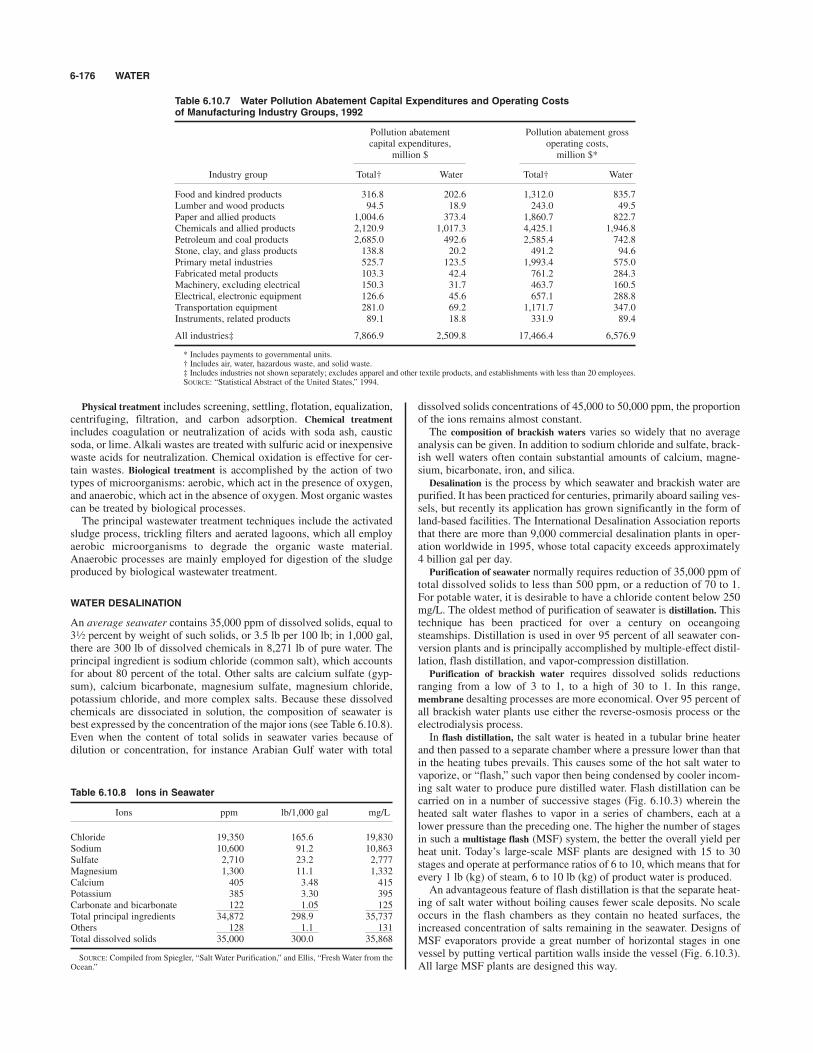
Physical treatment includes screening, settling, flotation, equalization,centrifuging, filtration, and carbon adsorption. Chemical treatmentincludes coagulation or neutralization of acids with soda ash, causticsoda, or lime. Alkali wastes are treated with sulfuric acid or inexpensivewaste acids for neutralization. Chemical oxidation is effective for cer-tain wastes. Biological treatment is accomplished by the action of twotypes of microorganisms: aerobic, which act in the presence of oxygen,and anaerobic, which act in the absence of oxygen. Most organic wastescan be treated by biological processes.The principal wastewater treatment techniques include the activated
sludge process, trickling filters and aerated lagoons, which all employaerobic microorganisms to degrade the organic waste material.Anaerobic processes are mainly employed for digestion of the sludgeproduced by biological wastewater treatment.
WATER DESALINATION
An average seawater contains 35,000 ppm of dissolved solids, equal to3 percent by weight of such solids, or 3.5 lb per 100 lb; in 1,000 gal,there are 300 lb of dissolved chemicals in 8,271 lb of pure water. Theprincipal ingredient is sodium chloride (common salt), which accountsfor about 80 percent of the total. Other salts are calcium sulfate (gyp-sum), calcium bicarbonate, magnesium sulfate, magnesium chloride,potassium chloride, and more complex salts. Because these dissolvedchemicals are dissociated in solution, the composition of seawater isbest expressed by the concentration of the major ions (see Table 6.10.8).Even when the content of total solids in seawater varies because ofdilution or concentration, for instance Arabian Gulf water with total
1⁄2
dissolved solids concentrations of 45,000 to 50,000 ppm, the proportionof the ions remains almost constant.The composition of brackish waters varies so widely that no average
analysis can be given. In addition to sodium chloride and sulfate, brack-ish well waters often contain substantial amounts of calcium, magne-sium, bicarbonate, iron, and silica.Desalination is the process by which seawater and brackish water are
purified. It has been practiced for centuries, primarily aboard sailing ves-sels, but recently its application has grown significantly in the form ofland-based facilities. The International Desalination Association reportsthat there are more than 9,000 commercial desalination plants in oper-ation worldwide in 1995, whose total capacity exceeds approximately4 billion gal per day.Purification of seawater normally requires reduction of 35,000 ppm of
total dissolved solids to less than 500 ppm, or a reduction of 70 to 1.For potable water, it is desirable to have a chloride content below 250mg/L. The oldest method of purification of seawater is distillation. Thistechnique has been practiced for over a century on oceangoingsteamships. Distillation is used in over 95 percent of all seawater con-version plants and is principally accomplished by multiple-effect distil-lation, flash distillation, and vapor-compression distillation. Purification of brackish water requires dissolved solids reductions
ranging from a low of 3 to 1, to a high of 30 to 1. In this range,membrane desalting processes are more economical. Over 95 percent ofall brackish water plants use either the reverse-osmosis process or theelectrodialysis process.In flash distillation, the salt water is heated in a tubular brine heater
and then passed to a separate chamber where a pressure lower than thatin the heating tubes prevails. This causes some of the hot salt water tovaporize, or “flash,” such vapor then being condensed by cooler incom-ing salt water to produce pure distilled water. Flash distillation can becarried on in a number of successive stages (Fig. 6.10.3) wherein theheated salt water flashes to vapor in a series of chambers, each at alower pressure than the preceding one. The higher the number of stagesin such a multistage flash (MSF) system, the better the overall yield perheat unit. Today’s large-scale MSF plants are designed with 15 to 30stages and operate at performance ratios of 6 to 10, which means that forevery 1 lb (kg) of steam, 6 to 10 lb (kg) of product water is produced.An advantageous feature of flash distillation is that the separate heat-
ing of salt water without boiling causes fewer scale deposits. No scaleoccurs in the flash chambers as they contain no heated surfaces, theincreased concentration of salts remaining in the seawater. Designs ofMSF evaporators provide a great number of horizontal stages in onevessel by putting vertical partition walls inside the vessel (Fig. 6.10.3).All large MSF plants are designed this way.
6-176 WATER
Table 6.10.7 Water Pollution Abatement Capital Expenditures and Operating Costs of Manufacturing Industry Groups, 1992
Pollution abatement Pollution abatement grosscapital expenditures, operating costs,
million $ million $*
Industry group Total† Water Total† Water
Food and kindred products 316.8 202.6 1,312.0 835.7Lumber and wood products 94.5 18.9 243.0 49.5Paper and allied products 1,004.6 373.4 1,860.7 822.7Chemicals and allied products 2,120.9 1,017.3 4,425.1 1,946.8Petroleum and coal products 2,685.0 492.6 2,585.4 742.8Stone, clay, and glass products 138.8 20.2 491.2 94.6Primary metal industries 525.7 123.5 1,993.4 575.0Fabricated metal products 103.3 42.4 761.2 284.3Machinery, excluding electrical 150.3 31.7 463.7 160.5Electrical, electronic equipment 126.6 45.6 657.1 288.8Transportation equipment 281.0 69.2 1,171.7 347.0Instruments, related products 89.1 18.8 331.9 89.4
All industries‡ 7,866.9 2,509.8 17,466.4 6,576.9
* Includes payments to governmental units.† Includes air, water, hazardous waste, and solid waste.‡ Includes industries not shown separately; excludes apparel and other textile products, and establishments with less than 20 employees.SOURCE: “Statistical Abstract of the United States,” 1994.
Table 6.10.8 Ions in Seawater
Ions ppm lb/1,000 gal mg/L
Chloride 19,350 165.6 19,830Sodium 10,600 91.2 10,863Sulfate 2,710 23.2 2,777Magnesium 1,300 11.1 1,332Calcium 405 3.48 415Potassium 385 3.30 395Carbonate and bicarbonate 122 1.05 125Total principal ingredients 34,872 298.9 35,737Others 128 1.1 131Total dissolved solids 35,000 300.0 35,868
SOURCE: Compiled from Spiegler, “Salt Water Purification,” and Ellis, “Fresh Water from theOcean.”
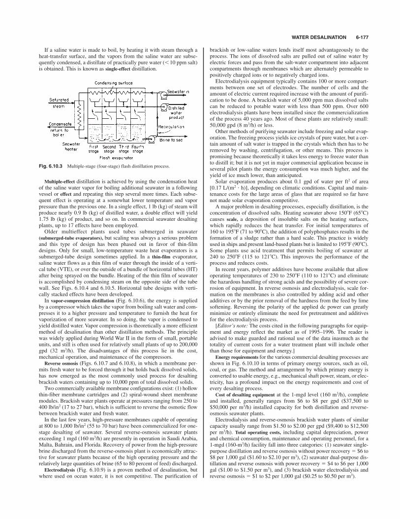
WATER DESALINATION 6-177
Multiple-effect distillation is achieved by using the condensation heatof the saline water vapor for boiling additional seawater in a followingvessel or effect and repeating this step several more times. Each subse-quent effect is operating at a somewhat lower temperature and vaporpressure than the previous one. In a single effect, 1 lb (kg) of steam willproduce nearly 0.9 lb (kg) of distilled water, a double effect will yield1.75 lb (kg) of product, and so on. In commercial seawater desaltingplants, up to 17 effects have been employed.Older multieffect plants used tubes submerged in seawater
(submerged-tube evaporators), but scaling was always a serious problemand this type of design has been phased out in favor of thin-filmdesigns. Only for small, low-temperature waste heat evaporators is asubmerged-tube design sometimes applied. In a thin-film evaporator,saline water flows as a thin film of water through the inside of a verti-cal tube (VTE), or over the outside of a bundle of horizontal tubes (HT)after being sprayed on the bundle. Heating of the thin film of seawateris accomplished by condensing steam on the opposite side of the tubewall. See Figs. 6.10.4 and 6.10.5. Horizontal tube designs with verti-cally stacked effects have been developed.In vapor-compression distillation (Fig. 6.10.6), the energy is supplied
by a compressor which takes the vapor from boiling salt water and com-presses it to a higher pressure and temperature to furnish the heat forvaporization of more seawater. In so doing, the vapor is condensed toyield distilled water. Vapor compression is theoretically a more efficientmethod of desalination than other distillation methods. The principlewas widely applied during World War II in the form of small, portableunits, and still is often used for relatively small plants of up to 200,000gpd (32 m3/h). The disadvantages of this process lie in the cost,mechanical operation, and maintenance of the compressors.Reverse osmosis (Figs. 6.10.7 and 6.10.8), in which a membrane per-
mits fresh water to be forced through it but holds back dissolved solids,has now emerged as the most commonly used process for desaltingbrackish waters containing up to 10,000 ppm of total dissolved solids.Two commercially available membrane configurations exist: (1) hollow
thin-fiber membrane cartridges and (2) spiral-wound sheet membranemodules. Brackish water plants operate at pressures ranging from 250 to400 lb/in2 (17 to 27 bar), which is sufficient to reverse the osmotic flowbetween brackish water and fresh water.In the last few years, high-pressure membranes capable of operating
at 800 to 1,000 lb/in2 (55 to 70 bar) have been commercialized for one-stage desalting of seawater. Several reverse-osmosis seawater plantsexceeding 1 mgd (160 m3/h) are presently in operation in Saudi Arabia,Malta, Bahrain, and Florida. Recovery of power from the high-pressurebrine discharged from the reverse-osmosis plant is economically attrac-tive for seawater plants because of the high operating pressure and therelatively large quantities of brine (65 to 80 percent of feed) discharged.Electrodialysis (Fig. 6.10.9) is a proven method of desalination, but
where used on ocean water, it is not competitive. The purification of
brackish or low-saline waters lends itself most advantageously to theprocess. The ions of dissolved salts are pulled out of saline water byelectric forces and pass from the salt-water compartment into adjacentcompartments through membranes which are alternately permeable topositively charged ions or to negatively charged ions.Electrodialysis equipment typically contains 100 or more compart-
ments between one set of electrodes. The number of cells and theamount of electric current required increase with the amount of purifi-cation to be done. A brackish water of 5,000 ppm max dissolved saltscan be reduced to potable water with less than 500 ppm. Over 600electrodialysis plants have been installed since the commercializationof the process 40 years ago. Most of these plants are relatively small:50,000 gpd (8 m3/h) or less.Other methods of purifying seawater include freezing and solar evap-
oration. The freezing process yields ice crystals of pure water, but a cer-tain amount of salt water is trapped in the crystals which then has to beremoved by washing, centrifugation, or other means. This process ispromising because theoretically it takes less energy to freeze water thanto distill it; but it is not yet in major commercial application because inseveral pilot plants the energy consumption was much higher, and theyield of ice much lower, than anticipated.Solar evaporation produces about 0.1 gpd of water per ft2 of area
[0.17 L/(m2 ' h)], depending on climatic conditions. Capital and main-tenance costs for the large areas of glass that are required so far havenot made solar evaporation competitive.A major problem in desalting processes, especially distillation, is the
concentration of dissolved salts. Heating seawater above 150*F (65*C)causes scale, a deposition of insoluble salts on the heating surfaces,which rapidly reduces the heat transfer. For initial temperatures of160 to 195*F (71 to 90*C), the addition of polyphosphates results in theformation of a sludge rather than a hard scale. This practice is widelyused in ships and present land-based plants but is limited to 195*F (90*C).Some plants use acid treatment that permits boiling of seawater at240 to 250*F (115 to 121*C). This improves the performance of theprocess and reduces costs.In recent years, polymer additives have become available that allow
operating temperatures of 230 to 250*F (110 to 121*C) and eliminatethe hazardous handling of strong acids and the possibility of severe cor-rosion of equipment. In reverse osmosis and electrodialysis, scale for-mation on the membranes is also controlled by adding acid and otheradditives or by the prior removal of the hardness from the feed by limesoftening. Reversing the polarity of the applied dc power can greatlyminimize or entirely eliminate the need for pretreatment and additivesfor the electrodialysis process.[Editor’s note: The costs cited in the following paragraphs for equip-
ment and energy reflect the market as of 1995–1996. The reader isadvised to make guarded and rational use of the data inasmuch as thetotality of current costs for a water treatment plant will include otherthan those for equipment and energy.] Energy requirements for the various commercial desalting processes are
shown in Fig. 6.10.10 in terms of primary energy sources, such as oil,coal, or gas. The method and arrangement by which primary energy isconverted to usable energy, e.g., mechanical shaft power, steam, or elec-tricity, has a profound impact on the energy requirements and cost ofevery desalting process.Cost of desalting equipment at the 1-mgd level (160 m3/h), complete
and installed, generally ranges from $6 to $8 per gpd ($37,500 to$50,000 per m3/h) installed capacity for both distillation and reverse-osmosis seawater plants.Electrodialysis and reverse-osmosis brackish water plants of similar
capacity usually range from $1.50 to $2.00 per gpd ($9,400 to $12,500per m3/h). Total operating costs, including capital depreciation, powerand chemical consumption, maintenance and operating personnel, for a1-mgd (160-m3/h) facility fall into three categories: (1) seawater single-purpose distillation and reverse osmosis without power recovery # $6 to$8 per 1,000 gal ($1.60 to $2.10 per m3), (2) seawater dual-purpose dis-tillation and reverse osmosis with power recovery # $4 to $6 per 1,000gal ($1.00 to $1.50 per m3), and (3) brackish water electrodialysis andreverse osmosis # $1 to $2 per 1,000 gal ($0.25 to $0.50 per m3).
Fig. 6.10.3 Multiple-stage (four-stage) flash distillation process.
If a saline water is made to boil, by heating it with steam through aheat-transfer surface, and the vapors from the saline water are subse-quently condensed, a distillate of practically pure water (!10 ppm salt)is obtained. This is known as single-effect distillation.

6-178
Fig 6.10.4
Vertical tube evaporator (VTE). Multieffect distillation process.
Fig 6.10.5
Horizontal tube multieffect evaporator (HTME). Multieffect distillation process.

6-179
Fig. 6.10.6 Vapor compression distillation process.
Fig. 6.10.7 Reverse-osmosis cell.
Fig. 6.10.9 Electrodialysis single-compartment process.
Fig. 6.10.10 Desalting primary energy requirements (Ammerlaan. Desalination,40, 1982, pp. 317–326.) Note: 1 metric ton (t) of oil # 43,800 MJ; 1 barrel (bbl)of oil # 6.2 TBtu; 1 kWh # 10.9 MJ # 10,220 Btu (large utility).
Fig 6.10.8 Reverse-osmosis plant block flow diagram.
(For general discussion of friction, viscosity, bearings, and coefficients of friction, see Secs. 3
and 8.)
REFERENCES: STLE, “Handbook of Lubrication,” 3 vols., CRC Press. ASME,“Wear Control Handbook.” ASM, “ASM Handbook,” vol. 18, “Friction,Lubrication, and Wear Technology.” ASTM, “Annual Book of ASTM Standards,”3 vols., “Petroleum Products and Lubricants.” NLGI, “Lubricating Grease Guide.”Fuller, “Theory and Practice of Lubrication for Engineers,” Wiley. Shigley andMischke, “Bearings and Lubrication: A Mechanical Designers’ Workbook,”McGraw-Hill. Stipina and Vesely, “Lubricants and Special Fluids,” Elsevier.Miller, “Lubricants and Their Applications,” McGraw-Hill. Shubkin (ed.),“Synthetic Lubricants and High Performance Functional Fluids,” Marcel Dekker.Bartz (ed.), “Engine Oils and Automotive Lubrication,” Dekker. Hamrock,“Fundamentals of Fluid Film Lubrication,” McGraw-Hill. Neale, “Lubrication: ATribology Handbook,” Butterworth-Heinemann. Ramsey, “Elastohydrodynamics,”Wiley. Arnell, “Tribology, Principles and Design Applications,” Springer-Verlag.Czichos, “Tribology, A Systems Approach to . . . Friction, Lubrication and Wear,”Elsevier. Bhushan and Gupta, “Handbook of Tribology: Materials, Coatings, andSurface Treatments,” McGraw-Hill. Yamaguchi, “Tribology of Plastic Materials,”Elsevier.
Tribology, a term introduced in the 1960s, is the science of rubbing sur-faces and their interactions, including friction, wear, and lubricationphenomena. Lubrication primarily concerns modifying friction andreducing wear and damage at the surface contacts of solids rubbingagainst one another. Anything introduced between the surfaces toaccomplish this is a lubricant.
LUBRICANTS
Lubricants can be liquids, solids, or even gases, and they are most oftenoils or greases. Liquid lubricants often provide many functions in addi-tion to controlling friction and wear, such as scavenging heat, dirt, andwear debris; preventing rust and corrosion; transferring force; and act-ing as a sealing medium.Engineers are called upon to select and evaluate lubricants, to follow
their performance in service, and to use them to best advantage in thedesign of equipment. Lubricant manufacturers and distributors mayhave hundreds of lubricants in their product line, each described sepa-rately in the product literature as to intended applications, properties,and benefits, as well as performance in selected standard tests.Lubricants are selected according to the needs of the particular applica-tion. Careful lubricant selection helps obtain improved performance,lower operating cost, and longer service life, for both the lubricant andthe equipment involved. Industry’s demands for efficient, competitiveequipment and operations, which meet the latest environmental regula-tions, create continued demand for new and improved lubricants.Equipment manufacturers and suppliers specify lubricants that suit theirparticular equipment and its intended operating conditions, and theirrecommendations should be followed.
LIQUID LUBRICANTS
A liquid lubricant consists of (1) a mixture of selected base oils andadditives, (2) blended to a specific viscosity, with (3) the blend designedto meet the performance needs of a particular type of service. A lubri-cant may contain several base oils of different viscosities and types,blended to meet viscosity requirements and to help meet performancerequirements, or to minimize cost. Additives may be used to help meetviscosity as well as various performance needs.
Petroleum Oils Lubricants made with petroleum base oils arewidely used because of their general suitability to much of existingequipment and availability at moderate cost. Most petroleum baseoils, often called mineral oils, are prepared by conventional refining
processes from naturally occurring hydrocarbons in crude oils. Themain crude oil types are paraffinic- and naphthenic-based, terms refer-ring to the type of chemical structure of most molecules. Paraffinic oilsare most often preferred as lubricants, although naphthenic oils areimportant in certain applications.The American Petroleum Institute (API) base stock categories were
established in the early 1990s to make it easier for lubricant blenders tointerchange one base stock for another (Table 6.11.1). The original fivecategories were patterned on the base oils which were available at thetime. Since that time, the lines between the categories have become lessdistinct, but these categories are still useful in describing base oils.
6-180
6.11 LUBRICANTS AND LUBRICATIONby Glenn E. Asauskas
Table 6.11.1 API Base Stock Categories
Group Sulfur, wt % Saturates, wt % VI*
I "0.03 and/or !90 80–119II !0.03 and "90 80–119III !0.03 and "90 "120IV All Polyalphaolefins (PAO)V All Stocks not included in Groups I-IV
(Pale Oils and non-PAO Synthetics)
*All commercial paraffinic base oils have VI " 95.
In general, older-technology base oils, produced by solvent refiningand solvent dewaxing technology, fall into group I. More modern baseoils, using hydroprocessing technology, fall into groups II and III(group III if the VI is 120 or greater). Polyalphaolefins (PAOs) aregroup IV, and everything else is group V. Thus, group V can includequite low-quality base stocks such as naphthenic base oils, as well asvery high-quality base stocks such as esters.Synthetic oils are artificially made, as opposed to naturally occurring
petroleum fluids. Synthetic oil types include polyalphaolefins (PAOs),diesters, polyol esters, alkylbenzenes, polyalkylene glycols, phosphateesters, silicones, and halogenated hydrocarbons. Synthetic oils includediverse types of chemical compounds, so few generalities apply to allsynthetic oils. Generally, synthetic oils are organic chemicals. Syntheticoils cost much more than petroleum oils, and usually they have somelubricant-related properties that are good or excellent, but they are notnecessarily strong in all properties. Their stronger properties ofteninclude greater high-temperature stability and oxidation resistance, widertemperature operating range, and improved energy efficiency. As withpetroleum base oils, some of their weaknesses are correctable by addi-tives. Some synthetic esters, such as polyol esters, have good biodegrad-ability, a property of increasing need for environmental protection.Synthetic lubricants, because of their high cost, often are used only
where some particular property is essential. There are instances wherethe higher cost of synthetics is justified, even though petroleum lubri-cants perform reasonably well. This may occur, e.g., where use of syn-thetics reduces the oxidation rate in high-temperature service and as aresult extends the oil life substantially. Properties of some syntheticlubricants are shown in Table 6.11.2, the assessments based on formu-lated lubricants, not necessarily the base oils. Synthetic oil uses includelubricants for gears, bearings, engines, hydraulic systems, greases,compressors, and refrigeration systems, although petroleum oils tend todominate these applications. Lubricants blended with both petroleumand synthetic base oils are called semisynthetic lubricants.Vegetable oils have very limited use as base stocks for lubricants, but
are used in special applications. Naturally occurring esters, such asfrom rapeseed or castor plants, are used as the base oils in some

VISCOSITY TESTS 6-181
hydraulic fluids, and are used where there are environmental concernsof possibility of an accidental fluid spill or leakage. These oils have ashorter life and lower maximum service temperature, but have a highdegree of biodegradability.Fatty oils, extracted from vegetable, animal, and fish sources, have
excellent lubricity because of their glyceride structure, but are seldomused as base oils because they oxidize rapidly. A few percent of fatty oilsare sometimes added to petroleum oils to improve lubricity (as in worm-gear applications), or to repel moisture (as in steam engines), and this useis often referred to as compounding. They also are used widely in formingsoaps which, in combination with other oils, set up grease structures.Additives are chemical compounds added to base oils to modify or
enhance certain lubricant performance characteristics. The amount ofadditives used varies with the type of lubricant, from a few parts per mil-lion in some types of lubricants to over 20 percent in some engine oils.The types of additives used include antioxidants, antiwear agents,extreme-pressure agents, viscosity index improvers, dispersants, deter-gents, pour point depressants, friction modifiers, corrosion inhibitors, rustinhibitors, metal deactivators, tackiness agents, antifoamants, air-releaseagents, demulsifiers, emulsifiers, odor control agents, and biocides.
LUBRICATION REGIMES
The viscosity of a lubricant and its additive content are to a large extentrelated to the lubrication regimes expected in its intended application. Itis desirable, but not always possible, to design mechanisms in which therubbing surfaces are totally separated by lubricant films. Hydrostaticlubrication concerns equipment designed such that the lubricant issupplied under sufficient pressure to separate the rubbing surfaces.Hydrodynamic lubrication is a more often used regime, and it occurswhen the motion of one surface over lubricant on the other surfacecauses sufficient film pressure and thickness to build up to separate thesurfaces. Achieving this requires certain design details, as well as oper-ation within a specific range of speed, load, and lubricant viscosity.Increasing speed or viscosity increases the film thickness, and increas-ing load reduces film thickness. Plain journal bearings, widely used inautomotive engines, operate in this regime. For concentrated noncon-forming contacts, such as rolling-element bearings, cams, and certaintype of gears, the surface shape and high local load squeeze the oil filmtoward surface contact. Under such conditions, elastohydrodynamiclubrication (EHL) may occur, where the high pressures in the film causeit to become very viscous and to elastically deform and separate thesurfaces.Boundary lubrication occurs when the load is carried almost entirely by
the rubbing surfaces, separated by films of only molecular dimensions.Mixed-film lubrication occurs when the load is carried partly by the oilfilm and partly by contact between the surfaces’ roughness peaks(asperities) rubbing one another. In mixed-film and boundary lubrica-tion, lubricant viscosity becomes less important and chemical composi-tion of the lubricant film more important. The films, although very thin,are needed to prevent surface damage. At loads up to a certain level,antiwear additives, the most common one being zinc dithiophosphate
(ZDTP), are used in the oil to form films to help support the load andreduce wear. ZDTP films can have thicknesses from molecular to muchlarger dimensions. In very highly loaded contacts, such as hypoid gears,extreme-pressure (EP) additives are used to minimize wear and preventscuffing. EP additives may contain sulfur, phosphorus, or chlorine, andthey react with the high-temperature contact surfaces to form molecu-lar-dimension films. Antiwear, EP, and friction modifier additives func-tion only in the mixed and boundary regimes.
LUBRICANT TESTING
Lubricants are manufactured to have specific characteristics, defined byphysical and chemical properties, and performance characteristics.Most of the tests used by the lubricants industry are described in ASTM(American Society for Testing and Materials) Standard Methods.Physical tests are frequently used to characterize petroleum oils, sincelubricant performance often depends upon or is related to physicalproperties. Common physical tests include measurements of viscosity,density, pour point, API gravity, flash point, fire point, odor, and color.Chemical tests measure such things as the amount of certain elements orcompounds in the additives, or the acidity of the oil, or the carbonresidue after heating the oil at high temperature. Performance testsevaluate particular aspects of in-service behavior, such as oxidation sta-bility, rust protection, ease of separation from water, resistance to foam-ing, and antiwear and extreme-pressure properties. Many of the testsused are small-size or bench tests, for practical reasons. To more closelysimulate service conditions, full-scale standardized performance testsare required for certain types of lubricants, such as oils for gasoline anddiesel engines. Beyond these industry standard tests, many equipmentbuilders require tests in specific machines or in the field. The full scopeof lubricant testing is rather complex, as simple physical and chemicaltests are incapable of fully defining in-service behavior.
VISCOSITY TESTS
Viscosity is perhaps the single most important property of a lubricant.Viscosity needs to be sufficient to maintain oil films thick enough tominimize friction and wear, but not so viscous as to cause excessiveefficiency losses. Viscosity reduces as oil temperature increases. Itincreases at high pressure and, for some fluids, reduces from shear, dur-ing movement in small clearances.Kinematic viscosity is the most common and fundamental viscosity
measurement, and it is obtained by oil flow by gravity through capillary-type instruments at low-shear-rate flow conditions. It is measured byASTM Standard Method D445. A large number of commercially avail-able capillary designs are acceptable. Automated multiple-capillarymachines also are sold. Kinematic viscosity is typically measured at40 and 100*C and is expressed in centistokes, cSt (mm2/s).Saybolt viscosity, with units of Saybolt universal seconds (SUS), was
once widely used. There is no longer a standard method for direct mea-surement of SUS. Some industrial consumers continue to use SUS, andit can be determined from kinematic viscosity using ASTM D2161.
Table 6.11.2 Relative Properties of Synthetic Lubricants*
High- Low-Viscosity temperature temperature Hydrolytic Fireindex stability Lubricity properties stability resistance Volatility
Polyalphaolefins Good Good Good Good Excellent Poor GoodDiesters Varies Excellent Good Excellent Fair Fair AveragePolyol esters Good Excellent Good Good Good Poor AverageAlkylbenzenes Poor Fair Good Good Excellent Poor AveragePolyalkylene glycols Excellent Good Good Good Good Poor GoodPhosphate esters Poor Excellent Good Varies Fair Excellent AverageSilicones Excellent Excellent Poor Excellent Fair — GoodFluorinated lubes Excellent Excellent Varies Fair Excellent Excellent Average
* Comparisons made for typical formulated products with additive packages, not for the base oils alone.SOURCE: Courtesy of Texaco’s magazine Lubrication, 78, no. 4, 1992.
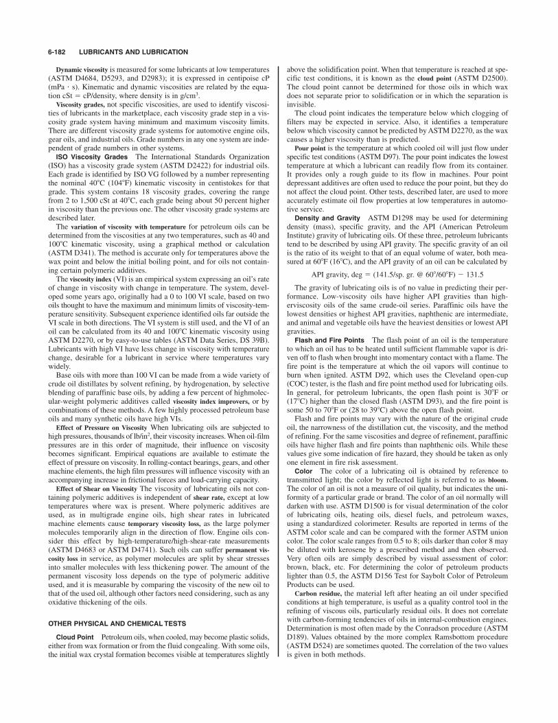
Dynamic viscosity is measured for some lubricants at low temperatures(ASTM D4684, D5293, and D2983); it is expressed in centipoise cP(mPa ' s). Kinematic and dynamic viscosities are related by the equa-tion cSt # cP/density, where density is in g/cm3.Viscosity grades, not specific viscosities, are used to identify viscosi-
ties of lubricants in the marketplace, each viscosity grade step in a vis-cosity grade system having minimum and maximum viscosity limits.There are different viscosity grade systems for automotive engine oils,gear oils, and industrial oils. Grade numbers in any one system are inde-pendent of grade numbers in other systems.
ISO Viscosity Grades The International Standards Organization(ISO) has a viscosity grade system (ASTM D2422) for industrial oils.Each grade is identified by ISO VG followed by a number representingthe nominal 40*C (104*F) kinematic viscosity in centistokes for thatgrade. This system contains 18 viscosity grades, covering the rangefrom 2 to 1,500 cSt at 40*C, each grade being about 50 percent higherin viscosity than the previous one. The other viscosity grade systems aredescribed later.The variation of viscosity with temperature for petroleum oils can be
determined from the viscosities at any two temperatures, such as 40 and100*C kinematic viscosity, using a graphical method or calculation(ASTM D341). The method is accurate only for temperatures above thewax point and below the initial boiling point, and for oils not contain-ing certain polymeric additives.The viscosity index (VI) is an empirical system expressing an oil’s rate
of change in viscosity with change in temperature. The system, devel-oped some years ago, originally had a 0 to 100 VI scale, based on twooils thought to have the maximum and minimum limits of viscosity-tem-perature sensitivity. Subsequent experience identified oils far outside theVI scale in both directions. The VI system is still used, and the VI of anoil can be calculated from its 40 and 100*C kinematic viscosity usingASTM D2270, or by easy-to-use tables (ASTM Data Series, DS 39B).Lubricants with high VI have less change in viscosity with temperaturechange, desirable for a lubricant in service where temperatures varywidely.Base oils with more than 100 VI can be made from a wide variety of
crude oil distillates by solvent refining, by hydrogenation, by selectiveblending of paraffinic base oils, by adding a few percent of highmolec-ular-weight polymeric additives called viscosity index improvers, or bycombinations of these methods. A few highly processed petroleum baseoils and many synthetic oils have high VIs.Effect of Pressure on Viscosity When lubricating oils are subjected to
high pressures, thousands of lb/in2, their viscosity increases. When oil-filmpressures are in this order of magnitude, their influence on viscositybecomes significant. Empirical equations are available to estimate theeffect of pressure on viscosity. In rolling-contact bearings, gears, and othermachine elements, the high film pressures will influence viscosity with anaccompanying increase in frictional forces and load-carrying capacity.Effect of Shear on Viscosity The viscosity of lubricating oils not con-
taining polymeric additives is independent of shear rate, except at lowtemperatures where wax is present. Where polymeric additives areused, as in multigrade engine oils, high shear rates in lubricatedmachine elements cause temporary viscosity loss, as the large polymermolecules temporarily align in the direction of flow. Engine oils con-sider this effect by high-temperature/high-shear-rate measurements(ASTM D4683 or ASTM D4741). Such oils can suffer permanent vis-cosity loss in service, as polymer molecules are split by shear stressesinto smaller molecules with less thickening power. The amount of thepermanent viscosity loss depends on the type of polymeric additiveused, and it is measurable by comparing the viscosity of the new oil tothat of the used oil, although other factors need considering, such as anyoxidative thickening of the oils.
OTHER PHYSICAL AND CHEMICAL TESTS
Cloud Point Petroleum oils, when cooled, may become plastic solids,either from wax formation or from the fluid congealing. With some oils,the initial wax crystal formation becomes visible at temperatures slightly
above the solidification point. When that temperature is reached at spe-cific test conditions, it is known as the cloud point (ASTM D2500).The cloud point cannot be determined for those oils in which waxdoes not separate prior to solidification or in which the separation isinvisible.The cloud point indicates the temperature below which clogging of
filters may be expected in service. Also, it identifies a temperaturebelow which viscosity cannot be predicted by ASTM D2270, as the waxcauses a higher viscosity than is predicted.Pour point is the temperature at which cooled oil will just flow under
specific test conditions (ASTM D97). The pour point indicates the lowesttemperature at which a lubricant can readily flow from its container.It provides only a rough guide to its flow in machines. Pour pointdepressant additives are often used to reduce the pour point, but they donot affect the cloud point. Other tests, described later, are used to moreaccurately estimate oil flow properties at low temperatures in automo-tive service.
Density and Gravity ASTM D1298 may be used for determiningdensity (mass), specific gravity, and the API (American PetroleumInstitute) gravity of lubricating oils. Of these three, petroleum lubricantstend to be described by using API gravity. The specific gravity of an oilis the ratio of its weight to that of an equal volume of water, both mea-sured at 60*F (16*C), and the API gravity of an oil can be calculated by
API gravity, deg # (141.5/sp. gr. @ 608/608F) $ 131.5
The gravity of lubricating oils is of no value in predicting their per-formance. Low-viscosity oils have higher API gravities than high-erviscosity oils of the same crude-oil series. Paraffinic oils have thelowest densities or highest API gravities, naphthenic are intermediate,and animal and vegetable oils have the heaviest densities or lowest APIgravities.
Flash and Fire Points The flash point of an oil is the temperatureto which an oil has to be heated until sufficient flammable vapor is dri-ven off to flash when brought into momentary contact with a flame. Thefire point is the temperature at which the oil vapors will continue toburn when ignited. ASTM D92, which uses the Cleveland open-cup(COC) tester, is the flash and fire point method used for lubricating oils.In general, for petroleum lubricants, the open flash point is 30*F or(17*C) higher than the closed flash (ASTM D93), and the fire point issome 50 to 70*F or (28 to 39*C) above the open flash point.Flash and fire points may vary with the nature of the original crude
oil, the narrowness of the distillation cut, the viscosity, and the methodof refining. For the same viscosities and degree of refinement, paraffinicoils have higher flash and fire points than naphthenic oils. While thesevalues give some indication of fire hazard, they should be taken as onlyone element in fire risk assessment.
Color The color of a lubricating oil is obtained by reference totransmitted light; the color by reflected light is referred to as bloom.The color of an oil is not a measure of oil quality, but indicates the uni-formity of a particular grade or brand. The color of an oil normally willdarken with use. ASTM D1500 is for visual determination of the colorof lubricating oils, heating oils, diesel fuels, and petroleum waxes,using a standardized colorimeter. Results are reported in terms of theASTM color scale and can be compared with the former ASTM unioncolor. The color scale ranges from 0.5 to 8; oils darker than color 8 maybe diluted with kerosene by a prescribed method and then observed.Very often oils are simply described by visual assessment of color:brown, black, etc. For determining the color of petroleum productslighter than 0.5, the ASTM D156 Test for Saybolt Color of PetroleumProducts can be used.Carbon residue, the material left after heating an oil under specified
conditions at high temperature, is useful as a quality control tool in therefining of viscous oils, particularly residual oils. It does not correlatewith carbon-forming tendencies of oils in internal-combustion engines.Determination is most often made by the Conradson procedure (ASTMD189). Values obtained by the more complex Ramsbottom procedure(ASTM D524) are sometimes quoted. The correlation of the two valuesis given in both methods.
6-182 LUBRICANTS AND LUBRICATION
GREASES 6-183
Ash Although it is unlikely that well-refined oils that do not con-tain metallic additives will yield any appreciable ash from impurities orcontaminants, measurement can be made by ASTM D482. A more use-ful determination is sulfated ash by ASTM D874, as applied to lubri-cants containing metallic additives.Neutralization number and total acid number are interchangeable terms
indicating a measure of acidic components in oils, as determined byASTM D664 or D974. The original intent was to indicate the degree ofrefining in new oils, and to follow the development of oxidation in ser-vice, with its effects on deposit formation and corrosion. However,many modern oils contain additives which, in these tests, act similar toundesirable acids and are indistinguishable from them. Caution must beexercised in interpreting results without knowledge of additive behav-ior. Change in acid number is more significant than the absolute valuein assessing the condition of an oil in service. Oxidation of an oil is usu-ally accompanied by an increase in acid number. Total base number (TBN) is a measure of alkaline components in oils,
especially those additives used in engine oils to neutralize acids formedduring fuel combustion. Some of these acids get in the crankcase withgases that blow by the rings. Today, TBN is generally measured byASTM D2896 or D4739, as it provides a better indication of an oil’sability to protect engines from corrosive wear than ASTM D664, whichwas previously used for TBN measurement.
Antifoam The foaming characteristic of crankcase, turbine, or cir-culating oils is checked by a foaming test apparatus (ASTM D892),which blows air through a diffuser in the oil. The test measures theamount of foam generated and the rate of settling. Certain additive oilstend to foam excessively in service. Many types of lubricants contain aminute quantity of antifoam inhibitor to prevent excessive foaming inservice. With the advent of the HEUI (hydraulically actuated, electron-ically controlled unit injector) fuel injection system, in diesel trucks, theNavistar 7.3L oil aeration test has become standard in API classificationCG-4, CH-4, Cl-4, and Cl-4 plus.
Oxidation Tests Lubricating oils may operate at relatively hightemperatures in the presence of air and catalytically active metals ormetallic compounds. Oxidation becomes significant when oil is operatedabove 150*F (66*C). Some lubricating-oil sump temperatures may exceed250*F (121*C). The oxidation rate doubles for about every 18*F (10*C)rise in oil temperature above 150*F (66*C). The resultant oil oxidationincreases viscosity, acids, sludge, and lacquer.To accelerate oxidation to obtain practical test length, oxidation tests
generally use temperatures above normal service, large amounts of cat-alytic metals, and sufficient oxygen. Two standard oxidation tests,ASTM D943 and D2272, are often applied to steam turbine and similarindustrial oils. There are many other standard oxidation tests for otherspecific lubricants. Because test conditions are somewhat removedfrom those encountered in service, care should be exercised in extrapo-lating results to expected performance in service.
Rust Prevention Lubricating oils are often expected to protect fer-rous surfaces from rusting when modest amounts of water enter thelubricating system. Many oils contain additives specifically designedfor that purpose. Steam turbine and similar industrial oils often are eval-uated for rust prevention by ASTM D665 and D3603. Where more pro-tection is required, as when a thin oil film must protect against amoisture-laden atmosphere, ASTM D1748 is a useful method.
Water Separation In many applications, it is desirable for the oil tohave good water-separating properties, to enable water removal beforeexcessive amounts accumulate and lead to rust and lubrication prob-lems. The demulsibility of an oil can be measured by ASTM D1401for light- to moderate-viscosity oils and by ASTM D2711 for heavier-viscosity oils.
Wear and EP Tests A variety of test equipment and methods havebeen developed for evaluating the wear protection and EP properties(load-carrying capacity before scuffing) of lubricant fluids and greasesunder different types of heavy-duty conditions. The tests are simplified,accelerated tests, and correlations to service conditions are seldomavailable, but they are important in comparing different manufacturers’products and are sometimes used in lubricant specifications. Each
apparatus tends to emphasize a particular characteristic, and a given lubri-cant will not necessarily show the same EP properties when tested ondifferent machines. ASTM methods D2783 (fluids) and D2509 (grease)use the Timken EP tester to characterize the EP properties of industrial-type gear lubricants, in tests with incremented load steps. ASTM D3233(fluids) uses the Falex pin and vee block tester for evaluating the EP prop-erties of oils and gear lubricants, using either continuous (method A) orincremented (method B) load increase during the test. Evaluation ofwear-prevention properties also can be conducted using this apparatus,by maintaining constant load. ASTM methods D2783 (fluids) andD2596 (grease) use the four-ball EP tester for evaluating the EP proper-ties of oils and greases. ASTM methods D4172 (fluids) and D2266(grease) use the four-ball wear tester to evaluate the wear-preventionproperties of oils and grease.
GREASES
Lubricating greases consist of lubricating liquid dispersed in a thicken-ing agent. The lubricating liquid is about 70 to 95 wt % of the finishedgrease and provides the principal lubrication, while the thickener holdsthe oil in place. Additives are often added to the grease to impart spe-cial properties. Grease helps seal the lubricating fluid in and the conta-minants out. Grease also can help reduce lubrication frequency,particularly in intermittent operation.The lubricating liquid is usually a napthenic or paraffinic petroleum
oil or a mixture of the two. Synthetic oils are used also, but because oftheir higher cost, they tend to be used only for specialty greases, suchas greases for very low or high temperature use. Synthetic oils used ingreases include polyalphaolefins, dialkylbenzenes, dibasic acid esters,polyalkylene glycols, silicones, and fluorinated hydrocarbons. The vis-cosity of the lubricating liquid in the grease should be the same aswould be selected if the lubricant were an oil.Soaps are the most common thickeners used in greases. Complex
soaps, pigments, modified clays, chemicals (such as polyurea), andpolymers are also used, alone or in combination. Soaps are formed byreaction of fatty material with strong alkalies, such as calcium hydrox-ide. In this saponification reaction, water, alcohol, and/or glycerin maybe formed as by-products. Soaps of weak alkalies, such as aluminum,are formed indirectly through further reactions. Metallic soaps, such assodium, calcium, and lithium, are the most widely used thickenerstoday.Additives may be incorporated in the grease to provide or enhance
tackiness, to provide load-carrying capability, to improve resistance tooxidation and rusting, to provide antiwear or EP properties, and tolessen sensitivity to water. The additives sometimes are solid lubricantssuch as graphite, molybdenum disulfide, metallic powders, or poly-mers, which grease can suspend better than oil. Solid fillers may beused to improve grease performance under extremely high loads orshock loads.The consistency or firmness is the characteristic which may cause
grease to be chosen over oil in some applications. Consistency is deter-mined by the depth to which a cone penetrates a grease sample underspecific conditions of weight, time, and temperature. In ASTM D217, astandardized cone is allowed to drop into the grease for 5 s at 77*F(25*C). The resulting depth of fall, or penetration, is measured intenths of millimeters. If the test is made on a sample simply transferredto a standard container, the results are called unworked penetration. Toobtain a more uniform sample, before the penetration test, the grease isworked for 60 strokes in a mechanical worker, a churnlike device.Variations on unworked and worked penetrations, such as prolongedworking, undisturbed penetration, or block penetration, also aredescribed in ASTM D217. The worked 60-stroke penetration is themost widely used indication of grease consistency. The NationalLubricating Grease Institute (NLGI) used this penetration method toestablish a system of consistency numbers to classify differences ingrease consistency or firmness. The consistency numbers range from000 to 6, each representing a range of 30 penetration units, and with a15 penetration unit gap between each grade, as shown in Table 6.11.3.

As grease is heated, it may change gradually from a semisolid to aliquid state, or its structure may weaken until a significant amount of oilis lost. Grease does not exhibit a true melting point, which implies asharp change in state. The weakening or softening behavior of greasewhen heated to a specific temperature can be defined in a carefully con-trolled heating program with well-defined conditions. This test gives atemperature called the dropping point, described in ASTM D566 or
applications. There are a large number of such materials, and theyinclude graphite, molybdenum disulfide, polytetrafluoroethylene,talc, graphite fluoride, polymers, and certain metal salts. The manydiverse types have a variety of different properties, operating ranges,and methods of application. The need for lubricants to operate atextremes of temperature and environment beyond the range of organicfluids, such as in the space programs, helped foster development ofsolid lubricants.One method of using solid lubricants is to apply them as thin films
on the bearing materials. The film thicknesses used range from 0.0002to 0.0005 in (0.005 to 0.013 mm). There are many ways to form thefilms. Surface preparation is very important in all of them. The sim-plest method is to apply them as unbonded solid lubricants, where gran-ular or powdered lubricant is applied by brushing, dipping, orspraying, or in a liquid or gas carrier for ease of application.Burnishing the surfaces is beneficial. The solid lubricant adheres tothe surface to some degree by mechanical or molecular action. Moredurable films can be made by using bonded solid lubricants, where thelubricant powders are mixed with binders before being applied to thesurface. Organic binders, if used, can be either room-temperature air-cured type or those requiring thermal setting. The latter tend to bemore durable. Air-cured films are generally limited to operating tem-peratures below 300*F (260*C), while some thermoset films may besatisfactory to 700*F (371*C). Inorganic ceramic adhesives combinedwith certain powdered metallic solid lubricants permit film use at tem-peratures in excess of 1,200*F (649*C). The performance of solid-lubricant films is influenced by the solid lubricant used, the method ofapplication, the bearing-surface-material finish and its hardness, thebinder-solid lubricant mix, the film and surface pretreatment, and theapplication’s operating conditions. Solidlubricant films can be evalu-ated in certain standard tests, including ASTM D2510 (adhesion),D2511 (thermal shock sensitivity), D2625 (wear endurance and loadcapacity), D2649 (corrosion characteristics), and D2981 (wear life byoscillating motion). Many plastics are also solid lubricants compared to the friction coef-
ficients typical of metals. Plastics are used without lubrication in manyapplications. Strong plastics can be compounded with a variety of solidlubricants to make plastics having both strength and low friction.Solidlubricant powders and plastics can be mixed, compacted, and sin-tered to form a lubricating solid, such as for a bearing. Such materialsalso can be made by combining solid-lubricant fibers with otherstronger plastic fibers, either woven together or chopped, and used incompressionmolded plastics. Bushings made of low-friction plasticmaterials may be press-fitted into metal sleeves. The varieties of low-friction plastic materials are too numerous to mention. Bearings madewith solid lowfriction plastic materials are commercially available.Solid lubricants may also be embedded in metal matrices to form
solid-lubricant composites of various desirable properties. Graphite isthe most common solid lubricant used, and others include molybdenumdisulfide and other metal-dichalcogenides. The base metals used include
6-184 LUBRICANTS AND LUBRICATION
Table 6.11.3 Grease Consistency Ranges
Consistencyno. Appearance Worked penetration
000 Semifluid 445–47500 Semifluid 400–4300 Semifluid 355–3851 Soft 310–3402 Medium 265–2953 Medium hard 220–2504 Hard 175–2055 Very hard 130–1606 Block type 85–115
D2265. Typical dropping points are given in Table 6.11.4. At itsdropping point, a grease already has become fluid, so the maximumapplication temperature must be well below the dropping point shownin the table. The oil constituent of a grease is loosely held. This is necessary for
some lubrication requirements, such as those of ball bearings. As aresult, on opening a container of grease, free oil is often seen. The ten-dency of a grease to bleed oil may be measured by ASTM D1742. Testresults are related to bleeding in storage, not in service or at elevatedtemperatures.Texture of a grease is determined by formulation and processing.
Typical textures are shown in Table 6.11.4. They are useful in identifi-cation of some products, but are of only limited assistance for predict-ing behavior in service. In general, smooth, buttery, short-fiber greasesare preferred for rolling-contact bearings and stringy, fibrous productsfor sliding service. Stringiness or tackiness imparted by polymeric addi-tives helps control leakage, but this property may be diminished oreliminated by the shearing action encountered in service.Grease performance depends only moderately on physical test char-
acteristics, such as penetration and dropping point. The likelihood ofsuitable performance may be indicated by these and other tests.However, the final determination of how a lubricating grease will per-form in service should be based on observations made in actual service.
SOLID LUBRICANTS
Solid lubricants are materials with low coefficients of friction comparedto metals, and they are used to reduce friction and wear in a variety of
Table 6.11.4 General Characteristics of Greases
Max usableTypical dropping temperature,* Water
Base Texture point, *F (*C) *F (*C) resistance Primary uses
Sodium Fibrous 325–350 (163–177) 200 (93) P–F Older, slower bearings with no waterCalcium Smooth 260–290 (127–143) 200 (93) E Moderate temperature, water presentLithium Smooth 380–395 (193–202) 250 (121) G General bearing lubrication12-hydroxystearatePolyurea Smooth 450& (232&) 350 (177) G–E Sealed-for-life bearingsCalcium complex Smooth 500& (260&) 350 (177) F–ELithium complex Smooth 450& (232&) 325 (163) G–E Used at high temperatures, with frequent relubricationAluminum complex Smooth 500& (260&) 350 (177) G–EOrganoclay Smooth 500& (260&) 250 (121) F–E
* Continuous operation with relatively infrequent lubrication.
¶
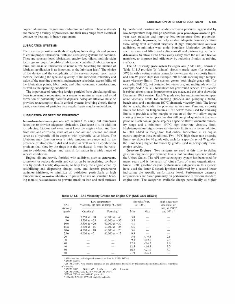
LUBRICATION OF SPECIFIC EQUIPMENT 6-185
copper, aluminum, magnesium, cadmium, and others. These materialsare made by a variety of processes, and their uses range from electricalcontacts to bearings in heavy equipment.
LUBRICATION SYSTEMS
There are many positive methods of applying lubricating oils and greasesto ensure proper lubrication. Bath and circulating systems are common.There are constant-level lubricators, gravity-feed oilers, multiple-sightfeeds, grease cups, forced-feed lubricators, centralized lubrication sys-tems, and air-mist lubricators, to name a few. Selecting the method oflubricant application is as important as the lubricant itself. The choiceof the device and the complexity of the system depend upon manyfactors, including the type and quantity of the lubricant, reliability andvalue of the machine elements, maintenance schedules, accessibility ofthe lubrication points, labor costs, and other economic considerations,as well as the operating conditions.The importance of removing foreign particles from circulating oil has
been increasingly recognized as a means to minimize wear and avoidformation of potentially harmful deposits. Adequate filtration must beprovided to accomplish this. In critical systems involving closely fittingparts, monitoring of particles on a regular basis may be undertaken.
LUBRICATION OF SPECIFIC EQUIPMENT
Internal-combustion-engine oils are required to carry out numerousfunctions to provide adequate lubrication. Crankcase oils, in additionto reducing friction and wear, must keep the engine clean and freefrom rust and corrosion, must act as a coolant and sealant, and mustserve as a hydraulic oil in engines with hydraulic valve lifters. Thelubricant may function over a wide temperature range and in thepresence of atmospheric dirt and water, as well as with combustionproducts that blow by the rings into the crankcase. It must be resis-tant to oxidation, sludge, and varnish formation in a wide range ofservice conditions. Engine oils are heavily fortified with additives, such as detergents,
to prevent or reduce deposits and corrosion by neutralizing combus-tion by-product acids; dispersants, to help keep the engine clean bysolubilizing and dispersing sludge, soot, and deposit precursors;oxidation inhibitors, to minimize oil oxidation, particularly at hightemperatures; corrosion inhibitors, to prevent attack on sensitive bear-ing metals; rust inhibitors, to prevent attack on iron and steel surfaces
by condensed moisture and acidic corrosion products, aggravated bylow-temperature stop-and-go operation; pour point depressants, to pre-vent wax gelation and improve low-temperature flow properties;viscosity-index improvers, to help enable adequate low-temperatureflow, along with sufficient viscosity at high temperatures; antiwearadditives, to minimize wear under boundary lubrication conditions,such as cam and lifter, and cylinder-wall and piston-ring surfaces;defoamants, to allow air to break away easily from the oil; and frictionmodifiers, to improve fuel efficiency by reducing friction at rubbingsurfaces.The SAE viscosity grade system for engine oils (SAE J300), shown in
Table 6.11.5 provides W (winter) viscosity grade steps (for example,5W) for oils meeting certain primarily low-temperature viscosity limits,and non-W grade steps (for example, 30) for oils meeting high-temper-ature viscosity limits. The system covers both single-grade oils (forexample, SAE 30), not designed for winter use, and multigrade oils (forexample, SAE 5 W-30), formulated for year-round service. This systemis subject to revision as improvements are made, and the table shows theDecember 1995 version. Each W grade step has maximum low-temper-ature viscosity limits for cranking (D5293) and pumping (D4684)bench tests, and a minimum 100*C kinematic viscosity limit. The lowerthe W grade, the colder the potential service use. Pumping viscositylimits are based on temperatures 10*C below those used for crankinglimits, to provide a safety margin so that an oil that will allow enginestarting at some low temperature also will pump adequately at that tem-perature. Each non-W grade step has a specific 100*C kinematic viscos-ity range and a minimum 150*C high-shear-rate viscosity limit.High-temperature high-shear-rate viscosity limits are a recent additionto J300, added in recognition that critical lubrication in an engineoccurs largely at these conditions. Two 150*C high-shear-rate viscositylimits are shown for 40 grade oils, each for a specific set of W grades,the limit being higher for viscosity grades used in heavy-duty dieselengine service.
Gasoline Engines Two systems are used at this time to definegasoline-engine-oil performance levels, not counting systems outsidethe United States. The API service category system has been used formany years and is the result of joint efforts of many organizations.Since 1970, gasoline engine performance categories in this systemhave used the letter S (spark ignition) followed by a second letterindicating the specific performance level. Performance categoryrequirements are based primarily on performance in various standardengine tests. The categories available change periodically as higher
Table 6.11.5 SAE Viscosity Grades for Engine Oila (SAE J300 DEC95)
Low temperature Viscosity,d cSt, High-shear-rateSAE viscosity, cP, max, at temp, *C, max at 100*C viscosity,e cP,
viscosity min, at 150*Cgrade Crankingb Pumpingc Min Max and 106 s$1
0W 3,250 at $30 60,000 at $40 3.8 — —5W 3,500 at $25 60,000 at $35 3.8 — —10W 3,500 at $20 60,000 at $30 4.1 — —15W 3,500 at $15 60,000 at $25 5.6 — —20W 4,500 at $10 60,000 at $20 5.6 — —25W 6,000 at $5 60,000 at $15 9.3 — —20 — — 5.6 ! 9.3 2.630 — — 9.3 !12.5 2.940 — — 12.5 !16.3 2.9 f
40 — — 12.5 !16.3 3.7g
50 — — 16.3 !21.9 3.760 — — 21.9 !26.1 3.7
a All values are critical specifications as defined in ASTM D3244.b ASTM D5293.cASTM D4684. Note that the presence of any yield stress detectable by this method constitutes a failure, regardless
of viscosity.d ASTM D445 Note: 1 cP # 1 mPa ' s 1 cSt # 1 mm2/se ASTM D4683, CEC L-36-A-90 (ASTM D4741)f 0W-40, 5W-40, and 10W-40 grade oils.g 15W-40, 20W-40, 25W-40, and 40 grade oils.

performance categories are needed for newer engines, and as oldercategories become obsolete when tests on which they are based areno longer available. At this writing, SM is the highest performancelevel for gasoline engines.The newer ILSAC system is based primarily on the same tests, but
has a few additional requirements. This system was developed by theInternational Lubricant Standardization and Approval Committee(ILSAC), a joint organization of primarily U.S. and Japanese automobileand engine manufacturers. The first category is in use, ILSAC GF-1.There are similarities as well as distinct differences between the two
systems. Both are displayed on oil containers using API licensed marks.The API service category system uses the API service symbol, andILSAC system uses the API certification mark, both shown in Fig. 6.11.1.Either or both marks can be displayed on an oil container. In the APIservice symbol, the performance level (SM), viscosity grade (SAE 5W30),and energy conserving for 5W20, 5W30, and 10W30 viscosity grades
levels, unlike the oils discussed above. They are products developed byreputable oil suppliers working with major engine builders. In general,they are formulated along the same lines as their automotive counter-parts. However, particularly in marine service where fuels often containrelatively high levels of sulfur, the detergent additive may be formulatedwith a high degree of alkalinity to neutralize sulfuric acid resulting fromcombustion.Gas engines pose somewhat different lubrication requirements. They
burn a clean fuel which gives rise to little soot, but conditions of oper-ation are such that nitrogen oxides formed during combustion can havea detrimental effect on the oil. Suitable lubricants may contain lessadditive than those which must operate in a sootier environment.However, the quality of the base oil itself assumes greater importance.Special selection of crude source and a high degree of refining must beobserved to obtain good performance. The most common viscosity isSAE 40, although SAE 30 is also used. Where cold starting is a factor,SAE 15W-40 oils are available.
Steam Turbines Although they do not impose especially severelubrication requirements, steam turbines are expected to run for verylong periods, often measured in many years, on the same oil charge.Beyond that, the oil must be able to cope with ingress of substantialamounts of water. Satisfactory products consist of highly refined baseoils with rust and oxidation (R&O) inhibitors, and they must show goodwater-separating properties (demulsifiability). There is demand forlonger-life turbine oil in the power generation industry, such as 6,000 hor more of life in the ASTM D943 oxidation bench test. This demand isbeing met by using more severely processed base oils and withimproved R&O inhibitors. Most large utility turbines operate with oilviscosity ISO VG 32. Where gearing is involved, ISO VG 100 is pre-ferred. Smaller industrial turbines, which do not have circulating sys-tems typical of large units, may operate with ISO VG 68. Circulatingsystems should be designed with removal of water in mind, whether bycentrifuge, coalescer, settling tank, or a combination of these methods.Where the turbine governor hydraulic system is separate from the cen-tral lubrication system, fire-resistant phosphate ester fluids are oftenused in the governor hydraulic system.Gas turbines in industrial service are lubricated with oils similar to the
ISO VG 32 product recommended for steam turbines; but to obtainacceptable service life under higher-temperature conditions, they maybe inhibited against oxidation to a greater extent. There is demand forlonger-life oils for gas turbines, and, as for steam turbines, the demandis being met by using more severely processed base oils and improvedR&O inhibitors. Gas turbines aboard aircraft operate at still higherbearing temperatures which are beyond the capability of petroleum oils.Synthetic organic esters are used, generally complying with militaryspecifications.
Gears API System of Lubricant Service Designations for AutomotiveManual Transmissions and Axles (SAE J308B) defines service levelsfor automotive gear oils. The service levels include API GL-1 to GL-6and API PL-1 to PL-2, related to gear types and service conditions.Also, there are SAE Viscosity Grades for Axle and TransmissionLubricants (SAE J306C) for gear oils in automotive service. In thissystem, there are winter grades from SAE 70 W to 85 W, based onlow-temperature viscosity (ASTM D2983) limits and 100*C kinematicviscosity (ASTM D445) limits, and grades from SAE 90 to 250, basedon 100*C kinematic viscosity limits. Many multigrade oils are marketedbased on it, capable of year-round operation.The American Gear Manufacturers Association (AGMA) has classifi-
cation systems for industrial gear lubricants, defined in AGMA 250.04and 251.02. These systems specify lubricant performance grades byAGMA lubricant numbers, each grade linked to a specific ISO viscositygrade. There are three systems for enclosed gear drives, and they cover(1) rust- and oxidation-inhibited, (2) extreme pressure, and (3) com-pounded lubricants. Three systems for open gear drives cover (1) rustandoxidation-inhibited, (2) extreme pressure, and (3) residual lubricants.The various gear types in use differ in severity of lubrication require-
ments. For spur, bevel, helical, and herringbone gears, clastohydrody-namic lubrication occurs at rated speeds and loads. Oils used for these
6-186 LUBRICANTS AND LUBRICATION
Fig. 6.11.1 API marks for engine oil containers. (From API Publication 1509,12th ed., 1993. Reprinted by courtesy of the American Petroleum Institute.)
are shown. None of these are shown in the API certification mark ofthe ILSAC system. The API certification mark remains unchanged asnew performance levels are developed and regardless of the viscositygrade of the oil in the container. ILSAC categories require the highestenergy-conserving level, and only allow a few viscosity grades, thoserecommended for newer engines. The viscosity grades allowed are SAEOW-20, 5W-20, 5W-30, and 10W-30. The viscosity grade may be dis-played separately. In the ILSAC system, to ensure high-performance-level oils, the API certification mark is licensed annually and only foroils meeting the latest ILSAC performance level.
Diesel Engines API performance-level categories for commercialheavy-duty diesel engine oils, using the API service category system,begin with the letter C (compression ignition), followed by additionalletters and numbers indicating the performance level and engine type,the performance letter changing as category improvements are needed.At this writing, Cl-4 plus is the highest performance category forfour-cycle turbocharged heavy-duty diesel engines, and CF-2 is thehighest for two-cycle turbocharged heavy-duty diesel engines. Viscositygrades used depend on the engine manufacturer’s recommendationsfor the ambient temperature range. SAE 15W-40 oils are very popularfor most four-cycle diesel engines, and single-grade oils, such asSAE 40, are used primarily in hotter climates and for two-cycle dieselengines.The engine oil is increasingly becoming a major part in the total
design, affecting performance of critical components as well as enginelife. Emission control restrictions are tightening up on diesel engines,and this is affecting the engine oils. Designs of pistons are changing,and rings are being located higher on the pistons and are more subjectto carbon deposits. Deposits are being controlled partly by use of properengine oils. One new engine design with reduced emissions uses theengine oil as hydraulic fluid to operate and improve control of the fuelinjectors, and this has created a need for improved oil deaeration per-formance. Most engine manufacturers maintain lists of oils that performwell in their engines.Larger diesel engines found in marine, railroad, and stationary ser-
vice use crankcase oils that are not standardized as to performance
LUBRICATION OF SPECIFIC EQUIPMENT 6-187
types of gears need not contain additives that contribute to oil filmstrength, but may contain antioxidants, rust inhibitors, defoamants, etc.,depending on the application. Worm gears need oils with film strengthadditives, such as compounded lubricants (containing fatty oils in apetroleum base), and use oils of relatively high viscosity, such as ISOVG 460. Other gear types, such as spur, use oils of widely varying vis-cosities, from ISO VG 46 to 460 or higher. The choice relates to oper-ating conditions, as well as any need to lubricate other mechanismswith the same oil. Hypoid gears, widely used in automobiles, need oilscontaining effective EP additives. There is increased use of syntheticgear oils where wide operating temperature ranges and need for longlife are involved. For example, polyalkylene glycol gear oils, whichhave high viscosity indices and excellent load capacities, are being usedin industrial applications involving heavily loaded or high-temperatureworm gears. Synthetic gear oils based on PAO base stocks have per-formed well in closed gearbox applications. With open gears, the lubri-cant often is applied sporadically and must adhere to the gear for sometime, resisting being scraped off by meshing teeth. Greases, and viscousasphaltic-base lubricants, often containing EP additives, are among thegear lubricants used in this service. Asphaltic products may be dilutedwith a solvent to ease application, the solvent evaporating relativelyquickly from the gear teeth.
Rolling-Contact Bearings These include ball bearings of variousconfigurations, as well as roller bearings of the cylindrical, spherical,and tapered varieties and needle bearings. They may range in size froma few millimetres to several metres. They are basically designed to carryload under EHL conditions, but considerable sliding motion may existas well as rolling motion at points of contact between rolling elementsand raceways. In addition, sliding occurs between rolling elements andseparators and, in roller bearings, between the ends of rollers and race-way flanges. In many instances, it is desirable to incorporate antiwearadditives to deal with these conditions.A choice can frequently be made between oil and grease. Where
the lubricant must carry heat away from the bearings, oil is the obvi-ous selection, especially where large quantities can be readily circu-lated. Also, where contamination by water and solids is difficult toavoid, oil is preferred, provided an adequate purification system isfurnished. If circulation is not practical, then grease may be the bet-ter choice. Where access to bearings is limited, grease may be indi-cated. Grease is also preferred in instances where leakage oflubricant might be a problem. Suitable oils generally contain rust and oxidation inhibitors, and anti-
wear additives. Viscosity is selected on the basis of EHL considerationsor builder recommendations for the particular equipment, and it mayrange anywhere from ISO VG 32 to 460, typically perhaps ISO VG 68.Where grease is employed, the selection of type will be governed by
operating conditions including temperature, loading, possibility ofwater contamination, and frequency and method of application. Lithium12-hydroxystearate grease, particularly of no. 2 consistency grade, iswidely used. Where equipment is lubricated for life at the time of man-ufacture, such as electric motors in household appliances, polyureagreases are often selected.
Air Compressors Reciprocating compressors require lubrication ofthe cylinder walls, packing, and bearings. Temperatures at the cylinderwall are fairly high, and sufficient viscosity must be provided. Oils ofISO VG from about 68 to 460 may be specified. Since water con-densation may be encountered, rust inhibitor is needed in addition tooxidation inhibitor. A principal operating problem concerning the lubri-cant is development of carbonaceous deposits on the valves and in thepiping. This can seriously interfere with valve operation and can lead todisastrous fires and explosions. It is essential to choose an oil with aminimum tendency to form such deposits. Conradson and Ramsbottomcarbon residue tests are of little value in predicting this behavior, andbuilders and reputable oil suppliers should be consulted. Maintenanceprocedures need to ensure that any deposits are cleaned on a regularbasis and not be allowed to accumulate. In units which call for all-loss lubrication to the cylinders, feed rates should be reduced to theminimum recommended levels to minimize deposit-forming tendencies.
Increasingly, certain synthetic oils, such as fully formulated diesters,polyalkylene glycols, and PAOs, are being recommended for longer,trouble-free operation.Screw compressors present a unique lubrication problem in that large
quantities of oil are sprayed into the air during compression. Exposureof large surfaces of oil droplets to hot air is an ideal environment foroxidation to occur. This can cause lacquer deposition to interfere withoil separator operation which is essential to good performance.Although general-purpose rust- and oxidation-inhibited oils, as well ascrankcase oils, are often used, they are not the best choice. Speciallyformulated petroleum oils, in ISO VG 32 to 68, are available for thesesevere conditions. For enhanced service life, synthetic organic ester flu-ids of comparable viscosity are often used.Refrigeration compressors vary in their lubricant requirements
depending on the refrigerant gas involved, particularly as some lubri-cant may be carried downstream of the compressor into the refrigera-tion system. If any wax from the lubricant deposits on evaporatorsurfaces, performance is seriously impaired. Ammonia systems canfunction with petroleum oils, even though ammonia is only poorlymiscible with such oils. Many lubricants of ISO VG 15 to 100 aresuitable, provided that the pour point is somewhat below evaporatortemperature and that it does not contain additives that react withammonia. Miscibility of refrigerant and lubricant is important tolubrication of some other types of systems. Chlorinated refrigerants(CFCs and HCFCs) are miscible with oil, and highly refined, low-pour, wax-free naphthenic oils of ISO VG 32 to 68 are often used, orcertain wax-free synthetic lubricants. CFC refrigerants, which depletethe ozone layer, will cease being produced after 1995. Chlorine-freehydrofluorocarbon (HFC) refrigerants are now widely used, as theyare non-ozone-depleting. HFCs are largely immisible in petroleum-based lubricants, but partial miscibility of refrigerant and lubricant isnecessary for adequate lubrication in these systems. Synthetic lubri-cants based on polyol ester or polyalkylene glycol base oils have mis-cibility with HFCs and are being used in HFC air conditioning andrefrigeration systems.
Hydraulic Systems Critical lubricated parts include pumps,motors, and valves. When operated at rated load, certain pumps andmotors are very sensitive to the lubricating quality of the hydraulicfluid. When the fluid is inadequate in this respect, premature wearoccurs, leading to erratic operation of the hydraulic system. Forindoor use, it is best to select specially formulated antiwear hydraulicoils. These contain rust and oxidation inhibitors as well as antiwearadditives, and they provide good overall performance in ISO VG32 to 68 for many applications. Newer hydraulic systems have higheroperating temperatures and pressures and longer drain intervals.These systems require oils with improved oxidation stability and anti-wear protection. Fluids with good filterability are being demanded toallow use of fine filters to protect the critical clearances of the system.Hydraulic fluids may contain VI improver and/or pour point depres-sant for use in low-temperature outside service, and antifoamants anddemulsifiers for rapid release of entrained air and water. Hydraulicequipment on mobile systems has greater access to automotivecrankcase oils and automatic transmission fluids and manufacturersmay recommend use of these oils in their equipment. Wherebiodegradability is of concern, fluids made of vegetable oil (rape-seed) are available.
Systems Needing Fire-Resistant Fluids Where accidental ruptureof an oil line may cause fluid to splash on a surface above about 600*F(310*C), a degree of fire resistance above that of petroleum oil is desir-able. Four classes of fluids, generally used in hydraulic systems operat-ing in such an environment, are available. Phosphate esters offer theadvantages of a good lubricant requiring little attention in service, butthey require special seals and paints and are quite expensive.Waterglycol fluids contain some 40 to 50 percent water, in a uniformsolution of diethylene glycol, or glycol and polyglycol, to achieveacceptable fire resistance. They require monitoring in service to ensureproper content of water and rust inhibitor. Invert emulsions contain 40 to50 percent water dispersed in petroleum oil. With oil as the outside

phase of the emulsion, lubrication properties are fairly good, but thefluid must be monitored to maintain water content and to ensure that thewater remains adequately dispersed. Finally, there are conventionalemulsions which contain 5 to 10 percent petroleum oil dispersed inwater. With the water as the outside phase, the fluid is a rather poorlubricant, and equipment requiring lubrication must be designed andselected to operate with these emulsions. Steps must also be taken toensure that problems such as rusting, spoilage, and microbial growthare controlled.Note that fire-resistant is a relative term, and it does not mean non-
flammable. Approvals of the requisite degree of fire resistance areissued by Factory Mutual Insurance Company and by the U.S. Bureauof Mines where underground mining operations are involved.
Metal Forming The functions of fluids in machining operationare (1) to cool and (2) to lubricate. Fluids remove the heat generatedby the chip/tool rubbing contact and/or the heat resulting from theplastic deformation of the work. Cooling aids tool life, preserves toolhardness, and helps to maintain the dimensions of the machinedparts. Fluids lubricate the chip/tool interface to reduce tool wear,frictional heat, and power consumption. Lubricants aid in the reduc-tion of metal welding and adhesion to improve surface finish. Thefluids may also serve to carry away chips and debris from the workas well as to protect machined surfaces, tools, and equipment fromrust and corrosion.Many types of fluids are used. Most frequently they are (1) mineral
oils, (2) soluble oil emulsions, or (3) chemicals or synthetics. These areoften compounded with additives to impart specific properties. Somemetalworking operations are conducted in a controlled gaseous atmos-phere (air, nitrogen, carbon dioxide).The choice of a metalworking fluid is very complicated. Factors to be
considered are (1) the metal to be machined, (2) the tools, and (3) the typeof operation. Tools are usually steel, carbide, or ceramic. In operationswhere chips are formed, the relative motion between the tool and chip ishigh-speed under high load and often at elevated temperature. In chiplessmetal forming—drawing, rolling, stamping, extruding, spinning—thefunction of the fluid is to (1) lubricate and cool the die and work materialand (2) reduce adhesion and welding on dies. In addition to fluids, solidssuch as talc, clay, and soft metals may be used in drawing operations.In addition to the primary function to lubricate and cool, the cutting
fluids should not (1) corrode, discolor, or form deposits on the work; (2)produce undesirable fumes, smoke, or odors; (3) have detrimental phys-ical effects on operators. Fluids should also be stable, resist bacterialgrowth, and be foam-resistant. In the machining operations, many combinations of tools, work-
pieces, and operating conditions may be encountered. In someinstances, straight mineral oils or oils with small amounts of additiveswill suffice, while in more severe conditions, highly compounded oilsare required. The effectiveness of the additives depends upon theirchemical activity with newly formed, highly reactive surfaces; thesecombined with the high temperatures and pressures at the contactpoints are ideal for chemical reactions. Additives include fatty oils, sul-fur, sulfurized fatty oils, and sulfurized, chlorinated, and phosphorusadditives. These agents react with the metals to form compoundswhich have a lower shear strength and may possess EP properties. Oilscontaining additives, either dark or transparent, are most widely usedin the industry.Oils with sulfur- and chlorine-based additives raise some issues of
increasing concern, as the more active sulfurized types stain copper andthe chlorinated types have environmental concerns and are not suitablefor titanium. New cutting oils have been developed which perform welland avoid these concerns.Water is probably the most effective coolant available but can seldom
be used as an effective cutting fluid. It has little value as a lubricant andwill promote rusting. One way of combining the cooling properties ofwater with the lubricating properties of oil is through the use of soluble
oils. These oils are compounded so they form a stable emulsion withwater. The main component, water, provides effective cooling while theoil and compounds impart desirable lubricating, EP, and corrosion-resistance properties.The ratio of water to oil will influence the relative lubrication and
cooling properties of the emulsion. For these nonmiscible liquids toform a stable emulsion, an emulsifier must be added. Water hardness isan important consideration in the forming of an emulsion, and protec-tion against bacterial growth should be provided. Care in preparing andhandling the emulsion will ensure more satisfactory performance andlonger life. Overheating, freezing, water evaporation, contamination,and excessive air mixing will adversely affect the emulsion. When oneis discarding the used emulsion, it is often necessary to “break” theemulsion into its oil and water components for proper disposal.Newer-technology soluble oils, using nonionic emulsifiers instead of
anionic emulsifiers, have improved properties over earlier-technologyoils, and have less tendency to form insoluble soaps with hard water,which results in fewer filter changes, less machine downtime, and lowermaintenance costs. They also have longer emulsion life, from greaterbacterial and fungal resistance.Water-soluble chemicals, and synthetics, are essentially solutions or
microdispersions of a number of ingredients in water. These materialsare used for the same purposes described above for mineral and solubleoils. Water-soluble synthetic fluids are seeing increased use and havegreater bioresistance than soluble oils and provide longer coolant lifeand lower maintenance.
Health Considerations Increased attention is being focused onhazards associated with manufacture, handling, and use of all types ofindustrial and consumer materials, and lubricants are no exception.Much progress has been made in removing substances suspected of cre-ating adverse effects on health. Suppliers can provide information ongeneral composition and potential hazards requiring special handling oftheir products, in the form of Material Safety Data Sheets (MSDSs). Itis seldom necessary to go further to ascertain health risks. It is neces-sary that personnel working with lubricants observe basic hygienicpractices. They should avoid wearing oil-soaked clothing, minimizeunnecessary exposure of skin, and wash exposed skin frequently withapproved soaps.
Used-Lubricant Disposal The nonpolluting disposal of used lubri-cants is becoming increasingly important and requires continual atten-tion. More and more legislation and control are being enacted, at local,state, and national levels, to regulate the disposal of wastes. Alternativemethods of handling specific used lubricants may be recommended,such as in situ purification and refortifying the oil and returning it toservice, often in mobile units provided by the lubricant distributor.Also, waste lubricating oils may be reprocessed into base oils for rere-fined lubricant manufacture. The use of waste lubricating oils as fuelsis being increasingly regulated because of air pollution dangers. Ifwastes are dumped on the ground or directly into sewers, they mayeventually be washed into streams and water supplies and become waterpollutants. They may also interfere with proper operation of sewageplants. Improper burning may contribute to air pollution. Wastes mustbe handled in such a way as to ensure nonpolluting disposal. Reputablelubricant suppliers are helpful in suggesting general disposal methods,although they cannot be expected to be knowledgeable about all localregulations.Lubricant management programs are being used increasingly by
industry to minimize operating cost, including lubricant, labor, andwaste disposal costs. These programs can be managed by lubricantuser/supplier teams. Fluid management programs include the followingactivities: lubrication selection; lubricant monitoring during service;reclamation and refortification; and disposal. The supplier and/or lubri-cant service firms often have the major role in performing the last threeactivities. These programs can be beneficial to both lubricant user andsupplier.
6-188 LUBRICANTS AND LUBRICATION

REFERENCES: Billmyer, “Textbook of Polymer Science,” 3d ed. Brydson, “PlasticsMaterials,” 4th ed. Birley, Heath, and Scott, “Plastics Materials: Properties andApplications.” Current publications of and sponsored by the Society of the PlasticsIndustry (SPI) and similar plastics industry organizations. Manufacturers’ specifi-cations, data, and test reports. “Modern Plastics Encyclopedia,” McGraw-Hill.
GENERAL OVERVIEW OF PLASTICS
Plastics are ubiquitous engineering materials which are wholly or in partcomposed of long, chainlike molecules called high polymers.While car-bon is the element common to all commercial high polymers, hydrogen,oxygen, nitrogen, sulfur, halogens, and silicon can be present in vary-ing proportions. High polymers may be divided into two classes:thermoplastic and thermosetting. The former reversibly melt to becomehighly viscous liquids and solidify upon cooling (Fig. 6.12.1). The resul-tant solids will be elastic, ductile, tough, or brittle, depending on thestructure of the solid as evolved from the molten state. Thermosettingpolymers are infusible without thermal or mechanical degradation.Thermosetting polymers (often termed thermosets) cure by a chain-linking chemical reaction usually initiated at elevated temperature andpressure, although there are types which cure at room temperaturethrough the use of catalysts. The more highly cured the polymer, thehigher its heat distortion temperature and the harder and more brittle itbecomes.
Some properties of plastics which are most desirable are highstrength/weight ratios and the ability to process raw materials throughto a finished size and shape in one of several basic operations; this lastitem has a large impact on the overall costs of finished products byvirtue of eliminating secondary operations.The seemingly endless variety of all types of plastics which are avail-
able in the marketplace is continually augmented by new compositions;if an end product basically lends itself to the use of plastics, there ismost likely to be some existing composition available to satisfy thedesign requirements. See Table 6.12.1.The properties of a given plastic can often be modified by the incor-
poration of additives into the basic plastic resin and include colorants,stabilizers, lubricants, and fibrous reinforcement. Likewise, where localstrength requirements are beyond the capacity of the plastic, ingeniousconfigurations of metallic inserts can be incorporated into the manufac-ture of the plastic part and become structurally integral with the partitself; female threaded inserts and male threaded studs are the mostcommon type of inserts found in plastic part production.Plastic resins may themselves be used as adhesives to join other plas-
tics or other paired materials including wood/wood, wood/plastic,metal/plastic, metal/metal, and wood/metal. Structural sandwich panels,with the inner layer of sheet or foamed plastic, are an adaptation ofcomposite construction.Foamed plastic has found widespread use as thermal insulation, a
volume filler, cushioning material, and many lightweight consumeritems.The ability to be recycled is an important attribute of thermoplastics;
thermosets are deficient in this regard. In view of the massive amountsof plastic in the consumer stream, recycling has become more the normthan the exception; indeed, in some jurisdictions, recycling of spentplastic consumables is mandated by law, while in others, the incentiveto recycle manifests itself as a built-in cost of the product—a tax, as itwere, imposed at the manufacturing phase of production to spur recy-cling efforts. (See Recycling on pages following.) In those cases where secondary operations are required to be per-
formed on plastic parts, the usual chip-producing material-removalprocesses are employed. In those regards, due diligence must be paid tothe nature of the material being cut. Thermoplastics will soften fromheat generated during cutting, and their low flexural modulus mayrequire backing to prevent excessive deflection in response to cuttingforces; thermosets may prove abrasive (even without fillers) and causerapid wear of cutting edges. Cutting operations on some soft thermo-plastics will experience elastic flow of the material beyond the cuttingregion, necessitating multiple cuts, each of smaller magnitude.The raw-materials cost for plastics will vary. The economies of quan-
tity production are self-evident from a study of applicable statistics ofplastics production. Consider that in 1993, global production of plasticraw materials was in excess of 100 million metric tons (t). The finaloverall cost of a finished plastic part is impacted by the cost of rawmaterials, of course, but further, the use of plastic itself affects thedesign, manufacture, and shipping components of the final cost; theselatter are not inconsequential in arriving at cost comparisons of produc-tion with plastics vis-à-vis metals. Suffice it to say that in general, whenall costs are accounted for and when design requirements can be metwith plastics, the end cost of a plastic item is often decidedly favorable.
RAW MATERIALS
The source of virgin raw materials, or feedstock, is generally petroleumor natural gas. The feedstock is converted to monomers, which thenbecome the basis for plastic resins. As recycling efforts increase,
6-189
6.12 PLASTICSStaff Contribution
Fig. 6.12.1 Tensile stress-strain curve for thermoplastic Lucite. (The Du Pont Co.)
As a class, plastics possess a combination of physical and mechanicalproperties which are attractive to the designer. There are certainproperties of plastics which cannot be replicated in metals, includinglight weight and density (specific gravity rarely greater than 2, with thenormal value in the range of 1.1 to 1.7—compare this with magnesium,the lightest structural metal of significance, whose specific gravity is1.75); optical properties which may range from complete clarity tocomplete opacity, with the ability to be compounded with through col-ors in an almost limitless range; low thermal conductivity and goodelectrical resistance; the ability to impart excellent surface finish toparts made by many of the primary production processes. Conversely,when compared to metals, plastics generally have lower elastic modu-lus—and thus, are inherently more flexible; have lower flexural andimpact strength, and inferior toughness; and have lower dimensionalstability generally than for most metals.

6-190
ABSa
Injection molding grades
ASTM 20%test Extrusion Heat- Medium- High- Platable Glass fiber-
Properties method grade ABS/Nylon resistant impact impact grade reinforced
1a. Melt flow, g/10 min D1238 0.85–1.0 1.1–1.8 1.1–1.8 1.1–18 1.1
1. Melting temperature, 8C.Tm (crystalline)
Tg (amorphous) 88–120 110–125 102–115 91–110 100–110 100–110
2. Processing temperature range, E:350–500 I:460–520 C:325–500 C:325–350 C:325–350 C:325–400 C:350–5008F. (C # compression; I :475–550 I:390–525 I:380–525 I:350–500 I:350–500T # transfer, I # injection;E # extrusion)
3. Molding pressure range, 8–25 8–25 8–25 8–25 8–25 15–30103 lb/in2
4. Compression ratio 2.5–2.7 1.1–2.0 1.1–2.0 1.1–2.0 1.1–2.0 1.1–2.0
5. Mold (linear) shrinkage, in/in D955 0.004–0.007 0.003–0.010 0.004–0.009 0.004–0.009 0.004–0.009 0.005–0.008 0.001–0.002
6. Tensile strength at break, lb/in2 D638b 2,500–8,000 4,000–6,000 4,800–7,500 5,500–7,500 4,400–6,300 5,200–6,400 10,500–13,000
7. Elongation at break, % D638b 20–100 40–300 3–45 5–60 5–75 2–3
8. Tensile yield strength, lb/in2 D638b 4,300–6,400 4,300–6,300 4,300–7,000 5,000–7,200 2,600–5,900 6,700
9. Compressive strength (rupture D695 5,200–10,000 7,200–10,000 1,800–12,500 4,500–8,000 13,000–14,000or yield), lb/in2
10. Flexural strength (rupture or D790 4,000–14,000 8,800–10,900 9,000–13,000 7,100–13,000 5,400–11,000 10,500–11,500 14,000–17,500yield), lb/in2
11. Tensile modulus, 103 lb/in2 D638b 130–420 260–320 285–360 300–400 150–350 320–380 740–880
12. Compressive modulus, 103 lb/in2 D695 150–390 190–440 200–450 140–300 800
13. Flexural modulus, 103 lb/in2 738F D790 130–440 250–310 300–400 310–400 179–375 340–390 650–800
2008F D790
2508F D790
3008F D790
14. Izod impact, ft ' lb/in of notch D256A 1.5–12 15–20 2.0–6.5 3.0–6.0 6.0–9.3 4.0–8.3 1.1–1.4( -in-thick specimen)
15. Hardness Rockwell D785 R75–115 R93–105 R100–115 R102–115 R85–106 R103–109 M85–98, R107
Shore/Barcol D2240/D2583
16. Coef. of linear thermal D696 60–130 90–110 60–93 80–100 95–110 47–53 20–21expansion, 106 in/(in ' 8C)
17. Deflection temperatureunder flexuralload, 8F 264 lb/in2 D648 170–220 130–150 220–240 200–220 205–215 190–222 210–220
annealed annealed annealed annealed181–193g
66 lb/in2 D648 170–235 180–195 230–245 215–225 210–225 215–222 220–230annealed annealed annealed annealed
18. Thermal conductivity, 10$4 C177 4.5–8.0 4.8cal ' cm/(s ' cm2 ' 8C)
19. Specific gravity D792 1.02–1.08 1.06–1.07 1.05–1.08 1.03–1.06 1.01–1.05 1.04–1.07 1.18–1.22
20. Water absorption ( -in-thickspecimen), %
24 h D570 0.20–0.45 0.20–0.45 0.20–0.45 0.20–0.45 0.18–0.20
Saturation D570
21. Dielectric strength ( -in- D149 350–500 350–500 350–500 350–500 420–550 450–460thick specimen), short time,V/mil)
NOTE: Footnotes a to f are at end of table.SOURCE: Abstracted from “Modern Plastics Encyclopedia,” 1995.
1⁄8
1⁄8
1⁄8
Physical
Thermal
Mechanical
Processing
Materials
Table 6.12.1 Properties of Plastic Resins and Compounds
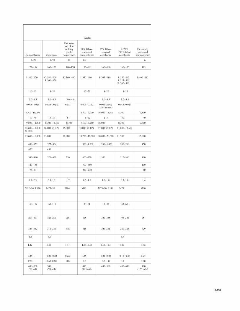
6-191
Acetal
Extrusionand blowmolding 20% Glass- 25% Glass- 2–20% Chemicallygrade reinforced coupled PTFE-filled lubricated
Homopolymer Copolymer (terpolymer) homopolymer copolymer copolymer homopolymer
1–20 1–90 1.0 6.0 6
172–184 160–175 160–170 175–181 160–180 160–175 175
I:380–470 C:340–400 E:360–400 I :350–480 I:365–480 I:350–445 I:400–440I:360–450 I:325–500
E:360–500
10–20 8–20 10–20 8–20 8–20
3.0–4.5 3.0–4.5 3.0–4.0 3.0–4.5 3.0–4.5
0.018–0.025 0.020 (Avg.) 0.02 0.009–0.012 0.004 (flow) 0.018–0.0290.018 (trans.)
9,700–10,000 8,500–9,000 16,000–18,500 8,300 9,500
10–75 15–75 67 6–12 2–3 30 40
9,500–12,000 8,300–10,400 8,700 7,500–8,250 16,000 8,300 9,500
15,600–18,000 16,000 @ 10% 16,000 18,000 @ 10% 17,000 @ 10% 11,000–12,600@ 10%
13,600–16,000 13,000 12,800 10,700–16,000 18,000–28,000 11,500 13,000
400–520 377–464 900–1,000 1,250–1,400 250–280 450
670 450
380–490 370–450 350 600–730 1,100 310–360 400
120–135 300–360 130
75–90 250–270 80
1.1–2.3 0.8–1.5 1.7 0.5–1.0 1.0–1.8 0.5–1.0 1.4
M92–94, R120 M75–90 M84 M90 M79–90, R110 M79 M90
50–112 61–110 33–81 17–44 52–68
253–277 185–250 205 315 320–325 198–225 257
324–342 311–330 318 345 327–331 280–325 329
5.5 5.5 4.7
1.42 1.40 1.41 1.54–1.56 1.58–1.61 1.40 1.42
0.25–1 0.20–0.22 0.22 0.25 0.22–0.29 0.15–0.26 0.27
0.90–1 0.65–0.80 0.8 1.0 0.8–1.0 0.5 1.00
400–500 500 490 480–580 400–410 400(90 mil) (90 mil) (125 mil) (125 mils)
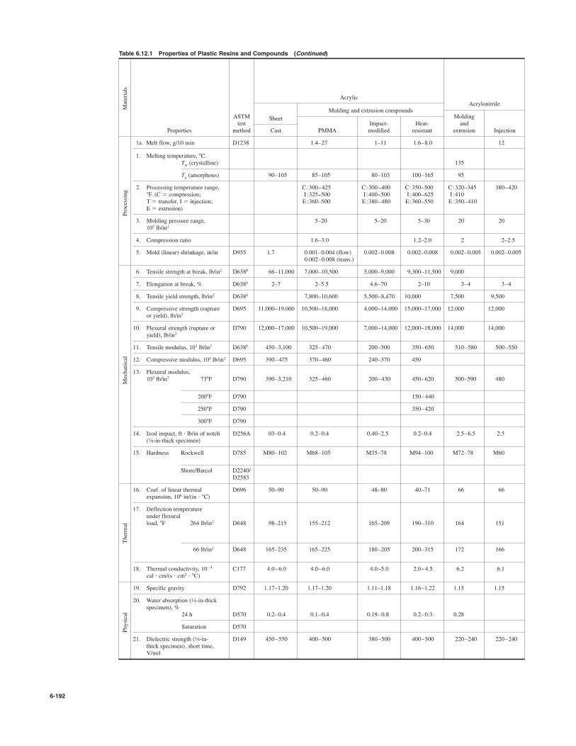
6-192
Table 6.12.1 Properties of Plastic Resins and Compounds (Continued)
AcrylicAcrylonitrile
ASTMMolding and extrusion compounds
Moldingtest
SheetImpact- Heat- and
Properties method Cast PMMA modified resistant extrusion Injection
1a. Melt flow, g/10 min D1238 1.4–27 1–11 1.6–8.0 12
1. Melting temperature, 8C.Tm (crystalline) 135
Tg (amorphous) 90–105 85–105 80–103 100–165 95
2. Processing temperature range, C:300–425 C:300–400 C:350–500 C:320–345 380–4208F. (C # compression; I :325–500 I:400–500 I:400–625 I:410T # transfer, I # injection; E:360–500 E:380–480 E:360–550 E:350–410E # extrusion)
3. Molding pressure range, 5–20 5–20 5–30 20 20103 lb/in2
4. Compression ratio 1.6–3.0 1.2–2.0 2 2–2.5
5. Mold (linear) shrinkage, in/in D955 1.7 0.001–0.004 (flow) 0.002–0.008 0.002–0.008 0.002–0.005 0.002–0.0050.002–0.008 (trans.)
6. Tensile strength at break, lb/in2 D638b 66–11,000 7,000–10,500 5,000–9,000 9,300–11,500 9,000
7. Elongation at break, % D638b 2–7 2–5.5 4.6–70 2–10 3–4 3–4
8. Tensile yield strength, lb/in2 D638b 7,800–10,600 5,500–8,470 10,000 7,500 9,500
9. Compressive strength (rupture D695 11,000–19,000 10,500–18,000 4,000–14,000 15,000–17,000 12,000 12,000or yield), lb/in2
10. Flexural strength (rupture or D790 12,000–17,000 10,500–19,000 7,000–14,000 12,000–18,000 14,000 14,000yield), lb/in2
11. Tensile modulus, 103 lb/in2 D638b 450–3,100 325–470 200–500 350–650 510–580 500–550
12. Compressive modulus, 103 lb/in2 D695 390–475 370–460 240–370 450
13. Flexural modulus,103 lb/in2 738F D790 390–3,210 325–460 200–430 450–620 500–590 480
2008F D790 150–440
2508F D790 350–420
3008F D790
14. Izod impact, ft ' lb/in of notch D256A 03–0.4 0.2–0.4 0.40–2.5 0.2–0.4 2.5–6.5 2.5( -in-thick specimen)
15. Hardness Rockwell D785 M80–102 M68–105 M35–78 M94–100 M72–78 M60
Shore/Barcol D2240/D2583
16. Coef. of linear thermal D696 50–90 50–90 48–80 40–71 66 66expansion, 106 in/(in ' 8C)
17. Deflection temperatureunder flexuralload, 8F 264 lb/in2 D648 98–215 155–212 165–209 190–310 164 151
66 lb/in2 D648 165–235 165–225 180–205 200–315 172 166
18. Thermal conductivity, 10$4 C177 4.0–6.0 4.0–6.0 4.0–5.0 2.0–4.5 6.2 6.1cal ' cm/(s ' cm2 ' 8C)
19. Specific gravity D792 1.17–1.20 1.17–1.20 1.11–1.18 1.16–1.22 1.15 1.15
20. Water absorption ( -in-thick specimen), %
24 h D570 0.2–0.4 0.1–0.4 0.19–0.8 0.2–0.3 0.28
Saturation D570
21. Dielectric strength ( -in- D149 450–550 400–500 380–500 400–500 220–240 220–240thick specimen), short time,V/mil
1⁄8
1⁄8
1⁄8
Physical
Thermal
Mechanical
Processing
Materials

6-193
Cellulosic Epoxy
Cellulose BisphenolEthyl acetate molding compounds
cellulose Cellulose acetate butyrate Casting resins and compoundsmolding Glasscompound Molding Molding fiber- Mineral- Aluminum-and sheet Sheet compound compound reinforced filled Unfilled filled Flexibilized
135 230 230 140 Thermoset Thermoset Thermoset Thermoset Thermoset
C:250–390 C:260–420 C:265–390 C:300–330 C:250–330I:350–500 I:335–490 I:335–480 T:280–380 T:250–380
8–32 8–32 8–32 1–5 0.1–3
1.8–2.4 1.8–2.6 1.8–2.4 3.0–7.0 2.0–3.0
0.005–0.009 0.003–0.010 0.003–0.009 0.001–0.008 0.002–0.010 0.001–0.010 0.001–0.005 0.001–0.010
2,000–8,000 4,500–8,000 1,900–9,000 2,600–6,900 5,000–20,000 4,000–10,800 4,000–13,000 7,000–12,000 2,000–10,000
5–40 20–50 6–70 40–88 4 3–6 0.5–3 20–85
2,500–6,300
3,000–8,000 2,100–7,500 18,000–40,000 18,000–40,000 15,000–25,000 15,000–33,000 1,000–14,000
4,000–12,000 6,000–10,000 2,000–16,000 1,800–9,300 8,000–30,000 6,000–18,000 13,000–21,000 8,500–24,000 1,000–13,000
50–200 3,000 350 350
650 1–350
1,200–4,000 90–300 2,000–4,500 1,400–2,000
0.4 2.0–8.5 1.0–7.8 1.0–10.9 0.3–10.0 0.3–0.5 0.2–1.0 0.4–1.6 2.3–5.0
R50–115 R85–120 R17–125 R31–116 M100–112 M100–M112 M80–110 M55–85
Shore D65–89
100–200 100–150 80–180 110–170 11–50 20–60 45–65 5.5 20–100
115–190 111–195 113–202 225–500 225–500 115–550 190–600 73–250
120–209 130–227
3.8–7.0 4–8 4–8 4–8 4.0–10.0 4–35 4.5 15–25
1.09–1.17 1.28–1.32 1.22–1.34 1.15–1.22 1.6–2.0 1.6–2.1 1.11–1.40 1.4–1.8 0.96–1.35
0.8–1.8 2.0–7.0 1.7–6.5 0.9–2.2 0.04–0.20 0.03–0.20 0.08–0.15 0.1–4.0 0.27–0.5
350–500 250–600 250–600 250–400 250–400 250–420 300–500 235–400

6-194
Table 6.12.1 Properties of Plastic Resins and Compounds (Continued)
Fluoroplastics
Polyvinylidene fluoride
Modified
Polytetrafluoroethylene EMI PE-TFEshielding
ASTM Polychloro- 25% Molding (conductive); 25%test trifluoro- Class fiber- and 30% PAN Glass fiber-
Properties method ethylene Granular reinforced extrusion carbon fiber reinforced
1a. Melt flow, g/10 min D1238
1. Melting temperature, 8C.Tm (crystalline) 327 327 141–178 270
Tg (amorphous) 220 $60 to $20
2. Processing temperature range, C:460–580 C:360–550 I:430–500 C:575–6258F. (C # compression; I :500–600 I:375–550 I:570–650T # transfer, I # injection; E:360–590 E:375–550E # extrusion)
3. Molding pressure range, 1–6 2–5 3–8 2–5 2–20103 lb/in2
4. Compression ratio 2.6 2.5–4.5 3
5. Mold (linear) shrinkage, in/in D955 0.010–0.015 0.030–0.060 0.018–0.020 0.020–0.035 0.001 0.002–0.030
6. Tensile strength at break, lb/in2 D638b 4,500–6,000 3,000–5,000 2,000–2,700 3,500–7,250 14,000 12,000
7. Elongation at break, % D638b 80–250 200–400 200–300 12–600 0.8 8
8. Tensile yield strength, lb/in2 D638b 5,300 2,900–8,250
9. Compressive strength (rupture D695 4,600–7,400 1,700 1,000–1,400 8,000–16,000 10,000or yield), lb/in2 @ 1% strain
10. Flexural strength (rupture, or D790 7,400–11,000 2,000 9,700–13,650 19,800 10,700yield), lb/in2
11. Tensile modulus, 103 lb/in2 D638b 58–80 200–240 200–80,000 2,800 1,200
12. Compressive modulus, 103 lb/in2 D695 150–300 60 304–420
13. Flexural modulus,103 lb/in2 738 F D790 170–200 80 190–235 170–120,000 2,100 950
2008F D790 180–260 450
2508F D790 310
3008F D790 200
14. Izod impact, ft ' lb/in of notch D256A 2.5–5 3 2.7 2.5–80 1.5 9.0( -in-thick specimen)
15. Hardness Rockwell D785 R75–112 R79–83, 85 R74
Shore/Barcol D2240/ Shore D75–80 Shore D50–65 Shore D60–70 Shore D80, 82D2583 65–70
16. Coef. of linear thermal D696 36–70 70–120 77–100 70–142 10–32expansion, 106 in/(in ' 8C)
17. Deflection temperatureunder flexuralload, 8F 264 lb/in2 D648 115 183–244 318 410
66 lb/in2 D648 258 160–250 280–284 510
18. Thermal conductivity, 10$4 C177 4.7–5.3 6.0 8–10 2.4–3.1cal ' cm/(s ' cm2 ' 8C)
19. Specific gravity D792 2.0.8–2.2 2.14–2.20 2.2–2.3 1.77–1.78 1.74 1.8
20. Water absorption ( -in-thickspecimen), %
24 h D570 0 !0.01 0.03–0.06 0.12 0.02
Saturation D570
21. Dielectric strength ( -in- D149 500–600 480 320 260–280 425thick specimen), short time,V/mil
1⁄8
1⁄8
1⁄8
Physical
Thermal
Mechanical
Processing
Materials

6-195
Phenolic
Molding compounds, phenol-formaldehyde
FuranHigh-strength
Impact-modified Casting
Asbestos- Wood glass fiber- Fabric- and Cellulose-resins
filled flour-filled reinforced rag-filled filled Unfilled
0.5–10
Thermoset Thermoset Thermoset Thermoset Thermoset Thermoset
C:275–300 C:290–380 C:300–380 C:290–380 C:290–380I:330–400 I:330–390 I:330–400 I:330–400
T:300–350 T:300–350
0.1–0.5 2–20 1–20 2–20 2–20
1.0–1.5 2.0–10.0 1.0–1.5 1.0–1.5
0.004–0.009 0.001–0.004 0.003–0.009 0.004–0.009
3,000–4,500 5,000–9,000 7,000–18,000 6,000–8,000 3,500–6,500 5,000–9,000
0.4–0.8 0.2 1–4 1–2 1.5–2.0
10,000–13,000 25,000–31,000 16,000–70,000 20,000–28,000 22,000–31,000 12,000–15,000
600–9,000 7,000–14,000 12,000–60,000 10,000–14,000 5,500–11,000 11,000–17,000
1,580 800–1,700 1,900–3,300 900–1,100 400–700
2,740–3,500
1,000–1,200 1,150–3,300 700–1,300 900–1,300
0.2–0.6 0.5–18.0 0.8–3.5 0.4–1.1 0.24–0.4
R110 M100–115 E54–101 M105–115 M95–115 M93–120
Barcol 72
30–45 8–34 18–24 20–31 68
300–370 350–600 325–400 300–350 165–175
4–8 8–14 9–12 6–9 3.5
1.75 1.37–1.46 1.69–2.0 1.37–1.45 1.38–1.42 1.24–1.32
0.01–0.02 0.3–1.2 0.03–1.2 0.6–0.8 05–0.9 0.1–0.36
0.12–1.5
260–400 140–400 200–370 300–380 250–400
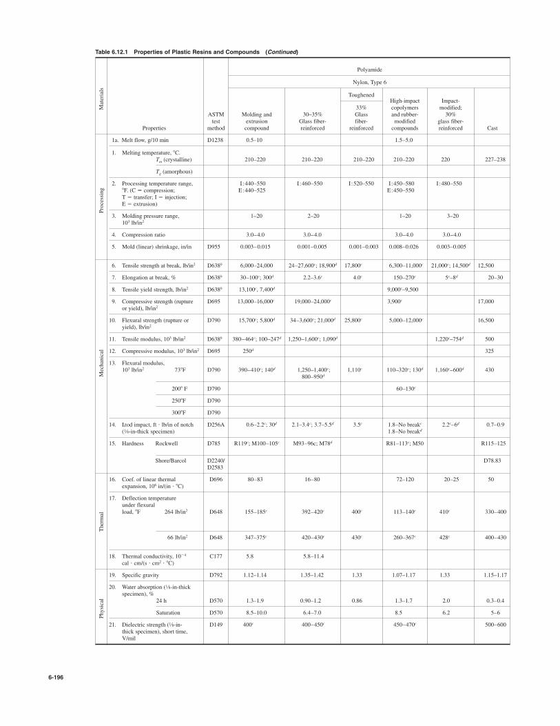
6-196
Table 6.12.1 Properties of Plastic Resins and Compounds (Continued)
Polyamide
Nylon, Type 6
ToughenedHigh-impact Impact-
33% copolymers modified;ASTM Molding and 30–35% Glass and rubber- 30%test extrusion Glass fiber- fiber- modified glass fiber-
Properties method compound reinforced reinforced compounds reinforced Cast
1a. Melt flow, g/10 min D1238 0.5–10 1.5–5.0
1. Melting temperature, 8C.Tm (crystalline) 210–220 210–220 210–220 210–220 220 227–238
Tg (amorphous)
2. Processing temperature range, I :440–550 I:460–550 I:520–550 I:450–580 I:480–5508F. (C # compression; E:440–525 E:450–550T # transfer; I # injection;E # extrusion)
3. Molding pressure range, 1–20 2–20 1–20 3–20103 lb/in2
4. Compression ratio 3.0–4.0 3.0–4.0 3.0–4.0 3.0–4.0
5. Mold (linear) shrinkage, in/in D955 0.003–0.015 0.001–0.005 0.001–0.003 0.008–0.026 0.003–0.005
6. Tensile strength at break, lb/in2 D638b 6,000–24,000 24–27,600c; 18,900d 17,800c 6,300–11,000c 21,000c; 14,500d 12,500
7. Elongation at break, % D638b 30–100c; 300d 2.2–3.6c 4.0c 150–270c 5c–8d 20–30
8. Tensile yield strength, lb/in2 D638b 13,100c, 7,400d 9,000c–9,500
9. Compressive strength (rupture D695 13,000–16,000c 19,000–24,000c 3,900c 17,000or yield), lb/in2
10. Flexural strength (rupture or D790 15,700c; 5,800d 34–3,600c; 21,000d 25,800c 5,000–12,000c 16,500yield), lb/in2
11. Tensile modulus, 103 lb/in2 D638b 380–464c; 100–247d 1,250–1,600c; 1,090d 1,220c–754d 500
12. Compressive modulus, 103 lb/in2 D695 250d 325
13. Flexural modulus,103 lb/in2 738F D790 390–410c; 140d 1,250–1,400c; 1,110c 110–320c; 130d 1,160c–600d 430
800–950d
2008 F D790 60–130c
2508F D790
3008F D790
14. Izod impact, ft ' lb/in of notch D256A 0.6–2.2c; 30d 2.1–3.4c; 3.7–5.5d 3.5c 1.8–No breakc 2.2c–6d 0.7–0.9( -in-thick specimen) 1.8–No breakd
15. Hardness Rockwell D785 R119c; M100–105c M93–96c; M78d R81–113c; M50 R115–125
Shore/Barcol D2240/ D78.83D2583
16. Coef. of linear thermal D696 80–83 16–80 72–120 20–25 50expansion, 106 in/(in ' 8C)
17. Deflection temperatureunder flexuralload, 8F 264 lb/in2 D648 155–185c 392–420c 400c 113–140c 410c 330–400
66 lb/in2 D648 347–375c 420–430c 430c 260–367c 428c 400–430
18. Thermal conductivity, 10$4 C177 5.8 5.8–11.4cal ' cm/(s ' cm2 ' 8C)
19. Specific gravity D792 1.12–1.14 1.35–1.42 1.33 1.07–1.17 1.33 1.15–1.17
20. Water absorption ( -in-thickspecimen), %
24 h D570 1.3–1.9 0.90–1.2 0.86 1.3–1.7 2.0 0.3–0.4
Saturation D570 8.5–10.0 6.4–7.0 8.5 6.2 5–6
21. Dielectric strength ( -in- D149 400c 400–450c 450–470c 500–600thick specimen), short time,V/mil
1⁄8
1⁄8
1⁄8
Physical
Thermal
Mechanical
Processing
Materials

6-197
Polyamide (Continued)
Nylon, Type 66
Toughened
Lubricated
30–33% Antifriction 5% MolybdenumGlass fiber- 15–33% Glass molybdenum disulfide and
Molding compound reinforced fiber-reinforced disulfide-filled 5% Silicone 30% PTFE 30% PTFE
255–265 260–265 256–265 249–265 260–265 260–265 260–265
I:500–620 I:510–580 I:530–575 I:500–600 I :530–570 I:530–570 I:530–570
1–25 5–20 5–25
3.0–4.0 3.0–4.0
0.007–0.018 0.002–0.006 0.0025–0.0045c 0.007–0.018 0.015 0.007 0.01
13,700c; 11,000d 27,600c; 20,300d 10,900–20,300c; 14,500d 10,500–13,700c 8,500c 5,500c 7,500c
15–80c; 150–300d 2.0–3.4c; 3–7d 4.7c; 8d 4.4–40c
8,000–12,000c; 6,500–8,500d 25,000c
12,500–15,000c (yld.) 24,000–40,000c 15,000c–20,000 12,000–12,500c
17,900–1,700c; 6,100d 40,000c; 29,000d 17,400–29,900c 15,000–20,300c 15,000c 8,000c 1,200c
230–550c; 230–500d 1,380c; 1,090d 1,230c; 943d 350–550c
410–470c; 185d 1,200–1,450c; 800d; 900 479–1,100c 420–495c 300c 460c 400c
0.55–1.0c; 0.85–2.1d 1.6–4.5c; 2.6–3.0d "3.2–5.0 0.9–4.5c 1.0c 0.5c 0.6c
R120c; M83c; M95–105d R101–119c; M101–102c; R107c; R115; R116; R119c
M96d M86c; M70d
80 15–54 43 54 63.0 45.0
158–212c 252–490c 446–470 190–260c 170 180 185
425–474c 260–500c 480–495 395–430
5.8 5.1–11.7
1.13–1.15 1.15–1.40 1.2–1.34 1.15–1.18 1.16 1.34 1.37
1.0–2.8 0.7–1.1 0.7–1.5 0.8–1.1 1.0 0.55 0.55
8.5 5.5–6.5 5 8.0
600c 360–500 360c

6-198
Table 6.12.1 Properties of Plastic Resins and Compounds (Continued)
Polycarbonate
Unfilled
Lubricatedmolding andImpact-extrusion
Glass fiber- modified 10–15%ASTM
resins
reinforced polycarbonate/ PTFE, 20%test High polyester glass fiber-
Properties method viscosity 10% glass blends reinforced
1a. Melt flow, g/10 min D1238 3–10 7.0
1. Melting temperature, 8C.Tm (crystalline)
Tg (amorphous) 150 150 150
2. Processing temperature range, I :560 I:520–650 I:475–560 I:590–6508F. (C # compression;T # transfer, I # injection;E # extrusion)
3. Molding pressure range, 10–20 10–20 15–20103 lb/in2
4. Compression ratio 1.74–5.5 2–2.5
5. Mold (linear) shrinkage, in/in D955 0.005–0.007 0.002–0.005 0.006–0.009 0.002
6. Tensile strength at break, lb/in2 D638b 9,100–10,500 7,000–10,000 7,600–8,500 12,000–15,000
7. Elongation at break, % D638b 110–120 4–10 120–165 2
8. Tensile yield strength, lb/in2 9,000 8,500–11,600 7,400–8,300
9. Compressive strength (rupture D695 10,000–12,500 12,000–14,000 7,000 11,000or yield), lb/in2
10. Flexural strength-(rupture or D790 12,500–13,500 13,700–16,000 10,900–12,500 18,000–23,000yield), lb/in2
11. Tensile modulus, 103 lb/in2 D638b 315 450–600 1,200
12. Compressive modulus, 103 lb/in2 D695 350 520
13. Flexural modulus,103 lb/in2 738F D790 330–340 460–580 280–325 850–900
2008F D790 275 440
2508F D790 245 420
3008F D790
14. Izod impact, ft ' lb/in of notch D256A 12–18 @ in 2–4 2–18 1.8–3.5( -in-thick specimen) 2.3 @ in
15. Hardness Rockwell D785 M70–M75 M62–75; R114–122R118–122
Shore/Barcol D2240/D2583
16. Coef. of linear thermal D696 68 32–38 80–95 21.6–23.4expansion, 106 in/(in ' 8C)
17. Deflection temperatureunder flexural load, 8F 264 lb/in2 D648 250–270 280–288 190–250 280–290
66 lb/in2 D648 280–287 295 223–265 290
18. Thermal conductivity, 10$4 C177 4.7 4.6–5.2 4.3cal ' cm/(s ' cm2 ' 8C)
19. Specific gravity D792 1.2 1.27–1.28 1.20–1.22 1.43–1.5
20. Water absorption ( -in-thickspecimen), %
24 h D570 0.15 0.12–0.15 0.12–0.16 0.11
Saturation D570 0.32–0.35 0.25–0.32 0.35–0.60
21. Dielectric strength ( -in- D149 380–"400 470–530 440–500thick specimen), short time, V/mil
1⁄8
1⁄8
1⁄41⁄8
1⁄8
Physical
Thermal
Mechanical
Processing
Materials

6-199
Polyester, thermoplastic Polyester, thermoset and alkyd
Polybutylene Polyethylene Glass fiber-terephthalate terephthalate reinforced
30% 30% Cast Preformed,Glass fiber- Glass fiber- chopped
Unfilled reinforced Unfilled reinforced Rigid Flexible roving
220–267 220–267 212–265 245–265 Thermoset Thermoset Thermoset
68–80
I:435–525 I:440–530 I:440–660 I:510–590E:520–580 C:170–320
4–10 5–15 2–7 4–20 0.25–2
3.1 2–3 1.0
0.009–0.022 0.002–0.008 0.002–0.030 0.002–0.009 0.0002–0.002
8,200–8,700 14,000–19,000 7,000–10,500 20,000–24,000 600–13,000 500–3,000 15,000–30,000
50–300 2–4 30–300 2–7 !2.6 40–310 1–5
8,200–8,700 8,600 23,000
8,600–14,500 18,000–23,500 11,000–15,000 25,000 13,000–30,000 15,000–30,000
12,000–16,700 22,000–29,000 12,000–18,000 30,000–36,000 8,500–23,000 10,000–40,000
280–435 1,300–1,450 400–600 1,300–1,440 300–640 800–2,000
375 700
330–400 850–1,200 350–450 1,200–1,590 490–610 1,000–3,000
520
390
0.7–1.0 0.9–2.0 0.25–0.7 1.5–2.2 0.2–0.4 "7 2–20
M68–78 M90 M94–101; R111 M90; M100
Barcol 35–75 Shore D84–94 Barcol 50–80
60–95 15–25 65 % 10$6 18–30 55–100 20–50
122–185 385–437 70–150 410–440 140–400 "400
240–375 421–500 167 470–480
4.2–6.9 7.0 3.3–3.6 6.0–7.6
1.30–1.38 1.48–1.53 1.29–1.40 1.55–1.70 1.04–1.46 1.01–1.20 1.35–2.30
0.08–0.09 0.06–0.08 0.1–0.2 0.05 0.15–0.6 0.5–2.5 0.01–1.0
0.4–0.5 0.35 0.2–0.3
420–550 460–560 420–550 430–650 380–500 250–400 350–500

6-200
Table 6.12.1 Properties of Plastic Resins and Compounds (Continued)
Polyethylene and ethylene copolymers
Low and medium density
LDPE
Cross-copolymers High density
linkedASTM Ethylene- Poly- Ultrahightest Linear vinyl ethylene molecular 30% Class Molding
Properties method copolymer acetate homopolymer weight fiber-reinforced grade
1a. Melt flow, g/10 min D1238 1.4–2.0 5–18
1. Melting temperature, 8C.Tm (crystalline) 122–124 103–110 130–137 125–138 120–140
Tg (amorphous)
2. Processing temperature range, I :350–500 C:200–300 I:350–500 C:400–500 I:350–600 C:240–4508F. (C # compression; E:450–600 I:350–430 E:350–525 I:250–300T # transfer; I # injection; E:300–380E # extrusion)
3. Molding pressure range, 5–15 1–20 12–15 1–2 10–20103 lb/in2
4. Compression ratio 3 2
5. Mold (linear) shrinkage, in/in D955 0.020–0.022 0.007–0.035 0.015–0.040 0.040 0.002–0.006 0.007–0.090
6. Tensile strength at break, lb/in2 D638b 1,900–4,000 2,200–4,000 3,200–4,500 5,600–7,000 7,500–9,000 1,600–4,600
7. Elongation at break, % D638b 100–965 200–750 10–1,200 420–525 1.5–2.5 10–440
8. Tensile yield strength, lb/in2 D638b 1,400–2,800 1,200–6,000 3,800–4,800 3,100–4,000
9. Compressive strength (rupture D695 2,700–3,600 6,000–7,000 2,000–5,500or yield), lb/in2
10. Flexural strength (rupture or D790 11,000–12,000 2,000–6,500yield), lb/in2
11. Tensile modulus, 103 lb/in2 D638b 38–75 7–29 155–158 700–900 50–500
12. Compressive modulus, 103 lb/in2 D695 50–150
13. Flexural modulus,103 lb/in2 738F D790 40–105 7.7 145–225 130–140 700–800 70–350
2008F D790
2508F D790
3008F D790
14. Izod impact, ft ' lb/in of notch D256A 1.0–No break No break 0.4–4.0 No break 1.1–1.5 1–20( -in-thick specimen)
15. Hardness Rockwell D785 R50 R75–90
Shore/Barcol D2240/ Shore D55–56 Shore D17–45 Shore D66–73 Shore D61–63 Shore D55–80D2583
16. Coef. of linear thermal D696 160–200 59–110 130–200 48 100expansion, 106 in/(in ' 8C)
17. Deflection temperatureunder flexuralload, 8F 264 lb/in2 D648 110–120 250 105–145
66 lb/in2 D648 175–196 155–180 260–265 130–225
18. Thermal conductivity, 10$4 C177 11–12 8.6–11cal ' cm/(s ' cm2 ' 8C)
19. Specific gravity D792 0.918–0.940 0.922–0.943 0.952–0.965 0.94 1.18–1.28 0.95–1.45
20. Water absorption ( -in-thickspecimen), %
24 h D570 0.005–0.13 !0.01 !0.01 0.02–0.06 0.01–0.06
Saturation D570
21. Dielectric strength ( -in- D149 620–760 450–500 710 500–550 230–550thick specimen), short time,V/mil
1⁄8
1⁄8
1⁄8
Physical
Thermal
Mechanical
Processing
Materials

6-201
Polyimide
Polypropylene
Thermoplastic Thermoset
Homopolymer
CopolymerImpact-
30% 50% 10–30% modified, 10–20%Glass fiber- Glass fiber- Glass fiber- 40% mica- Glass fiber-
Unfilled reinforced Unfilled reinforced Unfilled reinforced filled Unfilled reinforced
4.5–7.5 0.4–38.0 1–20 0.6–44.0 0.1–20
388 388 Thermoset Thermoset 160–175 168 168 150–175 160–168
250–365 250 $20 $20
C:625–690 I:734–788 460–485 C:460 I:375–550 I:425–475 I:350–470 I:375–550 I:350–480I:734–740 I:390 E:400–500 E:400–500E:734–740 T:390
3–20 10–30 7–29 3–10 10–20 10–20
1.7–4 1.7–2.3 1–1.2 2.0–2.4 2–2.4
0.0083 0.0044 0.001–0.01 0.002 0.010–0.025 0.002–0.008 0.007–0.008 0.010–0.025 0.003–0.01
10,500–17,100 24,000 4,300–22,900 6,400 4,500–6,000 6,500–13,000 4,500 4,000–5,500 5,000–8,000
7.5–90 3 1 100–600 1.8–7 4 200–500 3.0–4.0
12,500–13,000 4,300–22,900 4,500–5,400 7,000–10,000 3,000–4,300
17,500–40,000 27,500 19,300–32,900 34,000 5,500–8,000 6,500–8,400 3,500–8,000 5,500–5,600
10,000–28,800 35,200 6,500–50,000 21,300 6,000–8,000 7,000–20,000 7,000 5,000–7,000 7,000–11,000
300–400 1,720 460–4,650 165–225 700–1,000 700 130–180
315–350 458 421 150–300
360–500 1,390 422–3,000 1,980 170–250 310–780 600 130–200 355–510
50 40
35 30
210 1,175 1,030–2,690
1.5–1.7 2.2 0.65–15 5.6 0.4–1.4 1.0–2.2 0.7 1.1–14.0 0.95–2.7
E52–99, R129, M95 R128, M104 110M–120M M118 R80–102 R92–115 R65–96 R100–103
Shore D70–73
45–56 17–53 15–50 13 81–100 21–62 68–95
460–680 469 572–"575 660 120–140 253–288 205 130–140 260–280
225–250 290–320 185–220 305
2.3–4.2 8.9 5.5–12 8.5 2.8 5.5–6.2 3.5–4.0
1.33–1.43 1.56 1.41–1.9 1.6–1.7 0.900–0.910 0.97–1.14 1.23 0.890–0.905 0.98–1.04
0.24–0.34 0.23 0.45–125 0.7 0.01–0.03 0.01–0.05 0.03 0.01
1.2
415–560 528 480–508 450 600 600

6-202
Table 6.12.1 Properties of Plastic Resins and Compounds (Continued)
Polystyrene and styrene copolymers
Styrene copolymers
HighPolystyrene homopolymers Styrene- heat-resistant
20% LongRubber- acrylonitrile copolymers
ASTM High and and shortmodified (SAN)
20%test medium Heat- glass fiber- High- Molding Glass fiber-
Properties method flow resistant reinforced impact and extrusion reinforced
1a. Melt flow, g/10 min D1238 5.8
1. Melting temperature, 8C.Tm (crystalline)
Tg (amorphous) 74–105 100–110 115 9.3–105 100–200
2. Processing temperature range, C:300–400 C:300–400 I:400–550 I:350–525 C:300–400 I:425–5508F. (C # compression; I :350–500 I:350–500 E:375–500 I:360–550T # transfer; I # injection; E:350–500 E:350–500 E:360–450E # extrusion)
3. Molding pressure range, 5–20 5–20 10–20 10–20 5–20103 lb/in2
4. Compression ratio 3 3–5 4 3
5. Mold (linear) shrinkage, in/in D955 0.004–0.007 0.004–0.007 0.001–0.003 0.004–0.007 0.003–0.005 0.003–0.004
6. Tensile strength at break, lb/in2 D638b 5,200–7,500 6,440–8,200 10,000–12,000 1,900–6,200 10,000–11,900 10,000–14,000
7. Elongation at break, % D638b 1.2–2.5 2.0–3.6 1.0–1.3 20–65 2–3 1.4–3.5
8. Tensile yield strength, lb/in2 D638b 6,440–8,150 2,100–6,000 9,920–12,000
9. Compressive strength (rapture D695 12,000–13,000 13,000–14,000 16,000–17,000 14,000–15,000or yield), lb/in2
10. Flexural strength (rupture or D790 10,000–14,600 13,000–14,000 14,000–18,000 3,300–10,000 11,000–19,000 16,300–22,000yield), lb/in2
11. Tensile modulus, 103 lb/in2 D638b 330–475 450–485 900–1,200 160–370 475–560 850–900
12. Compressive modulus, 103 lb/in2 D695 480–490 495–500 530–580
13. Flexural modulus,103 lb/in2 738F D790 380–490 450–500 950–1,100 160–390 500–610 800–1,050
2008F D790
2508F D790
3008F D790
14. Izod impact, ft ' lb/in of notch D256A 0.35–0.45 0.4–0.45 0.9–2.5 0.95–7.0 0.4–0.6 2.1–2.6( -in-thick specimen)
15. Hardness Rockwell D785 M60–75 M75–84 M80–95, R119 R50–82; L–60 M80, R83
Shore/Barcol D2240/D2583
16. Coef. of linear thermal D696 50–83 68–85 39.6–40 44.2 65–68 20expansion, 106 in/(in ' 8C)
17. Deflection temperatureunder flexuralload, 8F 264 lb/in2 D648 169–202 194–217 200–220 170–205 214–220 231–247
66 lb/in2 D648 155–204 200–224 220–230 165–200 220–224
18. Thermal conductivity, 10$4 C177 3.0 3.0 5.9 3.0cal ' cm/(s ' cm2 ' 8C)
19. Specific gravity D792 1.04–1.05 1.04–1.05 1.20 1.03–1.06 1.06–1.08 1.20–1.22
20. Water absorption ( -in-thickspecimen), %
24 h D570 0.01–0.03 0.01 0.07–0.01 0.05–0.07 0.15–0.25 0.1
Saturation D570 0.01–0.03 0.01 0.3 0.5
21. Dielectric strength ( -in- D149 500–575 500–525 425 425thick specimen), short time,V/mil
1⁄8
1⁄8
1⁄8
Physical
Thermal
Mechanical
Processing
Materials

6-203
Polyurethane Silicone
Thermoset Thermoplastic Liquid Molding and
55–65% 10–20%Casting injection encapsulating
Mineral- Glass fiber-resins molding compounds
Casting resins filled potting reinforced Flexible Liquid Mineral-and casting Unreinforced molding (including silicone and/or
Liquid Unsaturated compounds molding compounds RTV) rubber glass-filled
Thermoset Thermoset Thermoset 75–137 Thermoset Thermoset Thermoset
120–160
C:43–250 25 (casting) I :430–500 I:360–410 I:360–420 C:280–360E:430–510 I:330–370
T:330–370
0.1–5 8–11 1–2 0.3–6
2.0–8.0
0.020 0.001–0.002 0.004–0.006 0.004–0.010 0.0–0.006 0.0–0.005 0.0–0.005
175–10,000 10,000–11,000 1,000–7,000 7,200–9,000 4,800–7,500 350–1,000 725–1,305 500–1,500
100–1,000 3–6 5–55 60–180 3–70 20–700 300–1,000 80–800
7,800–11,000
20,000 5,000
700–4,500 19,000 10,200–15,000 1,700–6,200
10–100 190–300 0.6–1.40
10–100
10–100 610 235–310 40–90
25 to flexible 0.4 1.5–1.8 10–14-No break
R" 100; M48 R45–55
Shore A10–13, Barcol 30–35 Shore A90, Shore A10–70 Shore A20–70 Shore A10–80D90 D52–85
100–200 71–100 34 10–19 10–20 20–50
Varies over 190–200 158–260 115–130 "500wide range
176–275 140–145
5 6.8–10 3.5–7.5 7.18
1.03–1.5 1.05 1.37–2.1 1.2 1.22–1.36 0.97–2.5 1.08–1.14 1.80–2.05
0.2–1.5 0.1–0.2 0.06–0.52 0.17–0.19 0.4–0.55 0.1 0.15
0.5–0.6 1.5 0.15–0.40
300–500 500–750 400 600 400–550 200–550@ in.1⁄16
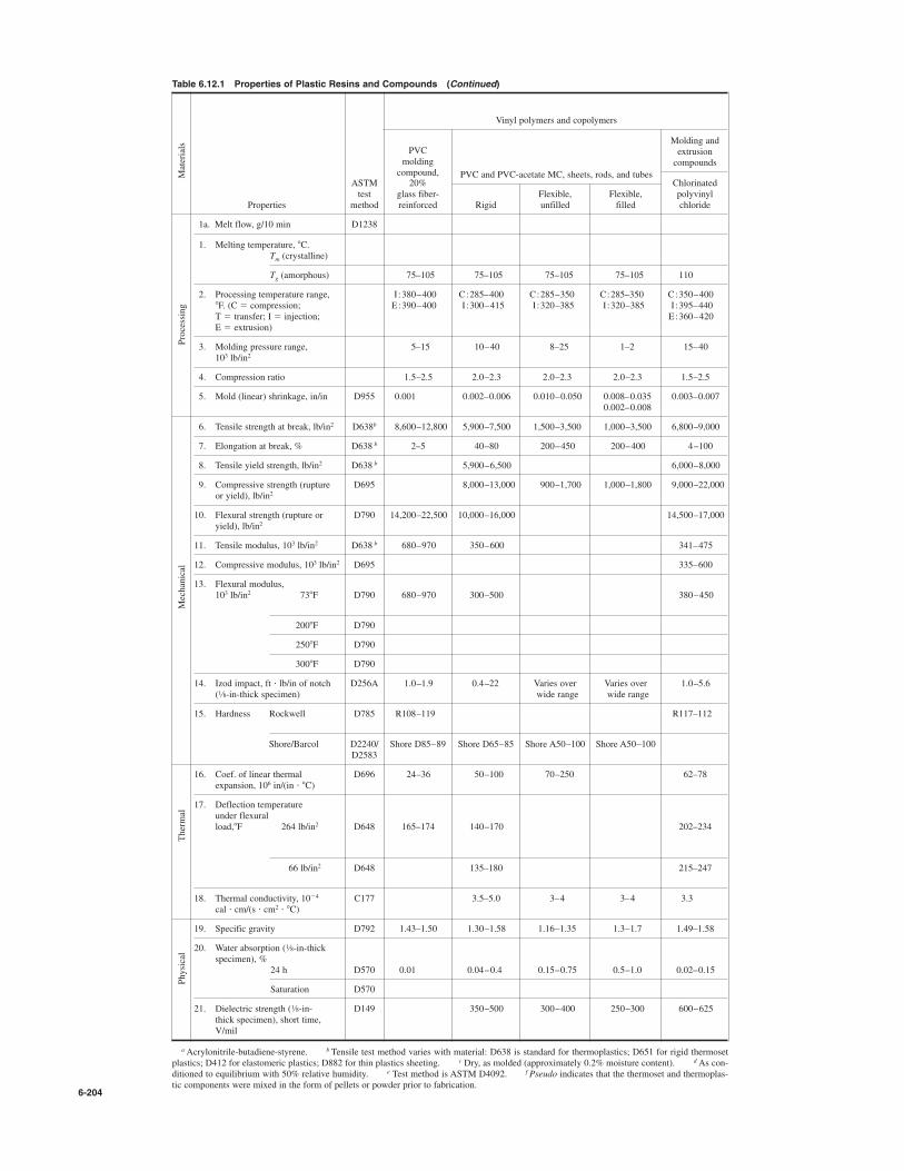
6-204
Table 6.12.1 Properties of Plastic Resins and Compounds (Continued)
Vinyl polymers and copolymers
PVCMolding and
moldingextrusion
compound, PVC and PVC-acetate MC, sheets, rods, and tubes
compounds
ASTM 20% Chlorinatedtest glass fiber- Flexible, Flexible, polyvinyl
Properties method reinforced Rigid unfilled filled chloride
1a. Melt flow, g/10 min D1238
1. Melting temperature, 8C.Tm (crystalline)
Tg (amorphous) 75–105 75–105 75–105 75–105 110
2. Processing temperature range, I :380–400 C:285–400 C:285–350 C:285–350 C:350–4008F. (C # compression; E:390–400 I:300–415 I:320–385 I:320–385 I:395–440T # transfer; I # injection; E:360–420E # extrusion)
3. Molding pressure range, 5–15 10–40 8–25 1–2 15–40103 lb/in2
4. Compression ratio 1.5–2.5 2.0–2.3 2.0–2.3 2.0–2.3 1.5–2.5
5. Mold (linear) shrinkage, in/in D955 0.001 0.002–0.006 0.010–0.050 0.008–0.035 0.003–0.0070.002–0.008
6. Tensile strength at break, lb/in2 D638b 8,600–12,800 5,900–7,500 1,500–3,500 1,000–3,500 6,800–9,000
7. Elongation at break, % D638 b 2–5 40–80 200–450 200–400 4–100
8. Tensile yield strength, lb/in2 D638 b 5,900–6,500 6,000–8,000
9. Compressive strength (rupture D695 8,000–13,000 900–1,700 1,000–1,800 9,000–22,000or yield), lb/in2
10. Flexural strength (rupture or D790 14,200–22,500 10,000–16,000 14,500–17,000yield), lb/in2
11. Tensile modulus, 103 lb/in2 D638 b 680–970 350–600 341–475
12. Compressive modulus, 103 lb/in2 D695 335–600
13. Flexural modulus,103 lb/in2 738F D790 680–970 300–500 380–450
2008F D790
2508F D790
3008F D790
14. Izod impact, ft ' lb/in of notch D256A 1.0–1.9 0.4–22 Varies over Varies over 1.0–5.6( -in-thick specimen) wide range wide range
15. Hardness Rockwell D785 R108–119 R117–112
Shore/Barcol D2240/ Shore D85–89 Shore D65–85 Shore A50–100 Shore A50–100D2583
16. Coef. of linear thermal D696 24–36 50–100 70–250 62–78expansion, 106 in/(in ' 8C)
17. Deflection temperatureunder flexuralload,8F 264 lb/in2 D648 165–174 140–170 202–234
66 lb/in2 D648 135–180 215–247
18. Thermal conductivity, 10$4 C177 3.5–5.0 3–4 3–4 3.3cal ' cm/(s ' cm2 ' 8C)
19. Specific gravity D792 1.43–1.50 1.30–1.58 1.16–1.35 1.3–1.7 1.49–1.58
20. Water absorption ( -in-thickspecimen), %
24 h D570 0.01 0.04–0.4 0.15–0.75 0.5–1.0 0.02–0.15
Saturation D570
21. Dielectric strength ( -in- D149 350–500 300–400 250–300 600–625thick specimen), short time,V/mil
aAcrylonitrile-butadiene-styrene. b Tensile test method varies with material: D638 is standard for thermoplastics; D651 for rigid thermosetplastics; D412 for elastomeric plastics; D882 for thin plastics sheeting. c Dry, as molded (approximately 0.2% moisture content). dAs con-ditioned to equilibrium with 50% relative humidity. e Test method is ASTM D4092. f Pseudo indicates that the thermoset and thermoplas-tic components were mixed in the form of pellets or powder prior to fabrication.
1⁄8
1⁄8
1⁄8
Physical
Thermal
Mechanical
Processing
Materials

RECYCLING 6-205
conversion of postconsumer plastic items (i.e., scrap) may result inincreasing amounts of plastics converted back to feedstock by applica-tion of hydrolytic and pyrolitic processes.The plastic is supplied to primary processers usually in the form of
powder, solid pellets, or plastisols (liquid or semisolid dispersions offinely powdered polymer in a nonmigrating liquid).Compounding, mixing, and blending prepare plastic materials to be
fed into any of the various fabrication processes.
PRIMARY FABRICATION PROCESSES
A number of processes are used to achieve finished plastic parts, includ-ing some conventional ones usually associated with metalworking andothers synonymous with plastics processing. Casting, blow molding,extrusion, forming in metal molds (injection, compression, and transfermolding), expanded-bead molding to make foams, thermoforming ofsheet plastic, filament winding over a form, press laminating, vacuumforming, and open molding (hand layup) are widespread plastics fabri-cation processes.
ADDITIVES
The inherent properties of most plastics can be tailored to impart otherdesired properties or to enhance existing ones by the introduction ofadditives. A wide variety of additives allow compounding a specifictype of plastic to meet some desired end result; a few additive types arelisted below.
Fillers Wood flour, mica, silica, clay, and natural synthetic fibersreduce weight, reduce the volume of bulk resin used, impart somespecific strength property (and often, directionality of strength prop-erties), etc.
Blowing or Foaming Agents Compressed gas or a liquid whichwill evolve gas when heated is the agent which causes the network ofinterstices in expanded foam. A popular foaming agent, CFC (chlori-nated fluorocarbon) is being displaced because of environmental con-cerns. Non-CFC foaming agents will increasingly replace CFCs.
Mold-Release Compounds These facilitate the removal of moldedparts from mold cavities with retention of surface finish on the finishedparts and elimination of pickup of molding material on mold surfaces.
Lubricants They ease fabrication and can serve to impart lubricantto plastic parts.
Antistatic Compounds The inherent good electrical insulationproperty of plastic often leads to buildup of static electric charges. Thestatic charge enhances dust pickup and retention to the plastic surface.At the very least, this may inhibit the action of a mold-release agent; atworst, the leakage of static electric charge may be an explosion or firehazard.
Antibacterial Agents (Biocides) These act to inhibit the growth ofbacteria, especially when the type of filler used can be an attractive hostto bacterial action (wood flour, for example).
Colorants Color is imparted to the resin by dyes or pigments. Dyesallow a wider range of color. Colorants enhance the utility of plastic prod-ucts where cosmetic and/or aesthetic effects are required. Ultraviolet (uv)radiation from sunlight degrades the color unless a uv-inhibiting agentis incorporated into the plastic resin. (See below.)
Flame Retardants These are introduced primarily for safety, andthey work by increasing the ignition temperature and lowering the rateof combustion.
Heat Stabilizers Plastics will degrade when subjected to high tem-peratures; thermoplastics will soften and eventually melt; thermosetswill char and burn. Either type of plastic part is subjected to heat dur-ing processing and may see service above room temperature during itsuseful life. The judicious addition of an appropriate heat-stabilizingcompound will prevent thermal degradation under those circumstances.Some of the more effective heat-stabilizing agents contain lead, anti-mony, or cadmium and are subject to increasingly stringent environ-mental limits.
Impact Modifiers When added to the basic resin, these materialsincrease impact strength or toughness.
Plasticizers These materials increase the softness and flexibility ofthe plastic resin, but often there is an accompanying loss of tensilestrength, increased flammability, etc.
Ultraviolet Stabilizers These additives retard or prevent the degra-dation of some strength properties as well as color, which result fromexposure to sunlight.
Antioxidants Substances compounded with plastic resin that act toprevent oxidative degeneration which may be brought about by expo-sure to heat, radiation, impurities, or high shear loads.
ADHESIVES, ASSEMBLY, AND FINISHES
Most adhesives operate to effect solvent-based bonding, and they areeither one- or two-part materials. While these adhesives cure, the evap-oration of volatile organic compounds (VOCs) constitutes an environ-mental hazard which is subject to increasing regulation. Water-basedbonding agents, on the other hand, emit no VOCs and effectively areenvironmentally benign. Adhesives which are constituted of all solidmaterial contain no solvents or water, hence no evaporants. A smallquantity of bonding is performed via radiation-curable adhesives. Thesource of energy is ultraviolet radiation or electron beam radiation. The adhesives cited above, and others, display a range of properties
which must be assessed as to suitability for the application intended.Welding of plasticsmost often implies bonding or sealing of plastic sheet
through the agent of ultrasonic energy, which, when applied locally, trans-forms high-frequency ultrasonic energy to heat, which, in turn, fuses theplastic locally to achieve the bond. The design of the joint is critical tothe successful application of ultrasonic welding when the pieces areother than thin sheets. Solvent welding consists of localized softening ofthe pieces to be joined and the intimate mixture of the plastic surfacematerial of both parts. The solvent is usually applied with the partsfixed or clamped in place, and sufficient time is allowed for the solventto react locally with the plastic surfaces and then evaporate.Most plastic pieces are amenable to the application of decorative fin-
ishes either during fabrication (e.g., in the mold) or as a secondary oper-ation. Suitable paints are applied as required, often via silk screening.Electrolytic plating, vacuum metallizing, hot stamping, printing, andapplication of labels via pressure-sensitive adhesives are well-establishedmethods in wide use.
RECYCLING
The feedstock for all plastics is either petroleum or natural gas. Thesematerials constitute a valuable and irreplaceable natural resource.Plastic materials may degrade; plastic parts may break or no longer beof service; certainly, very little plastic per se “wears away.” The basicidea behind plastic recycling takes a leaf from the metal industries,where recycling scrap metals has been the modus operendi from ancienttimes. The waste of a valuable resource implicit in discarding scrapplastic in landfills or the often environmentally hazardous incinerationof plastics has led to very strong efforts toward recycling plastic scrap.
Separation of plastic by types, aided by unique identification sym-bols molded into consumer items, is mandated by law in many locali-ties which operate an active recycling program. Different plastic typespresent a problem when comingled during recycling, but some postre-cycling consumer goods have found their way to the market. Effortswill continue as recycling of plastics becomes universal; the costs asso-ciated with the overall recycling effort will become more attractive aseconomies of large-scale operations come into play.Ideally, plastic recycling responds best to clean scrap segregated as to
type. In reality, this is not the case, and for those reasons, a number ofpromising scrap processing directions are being investigated. Amongthose is depolymerization, whereby the stream of plastic scrap is sub-jected to pyrolitic or hydrolytic processing which results in reversion ofthe plastic to feedstock components. This regenerated feedstock canthen be processed once more into the monomers, then to virgin poly-meric resins. Other concepts will come under consideration in the nearfuture.

REFERENCES: Jones, “Mechanics of Composite Materials,” HemispherePublishing. Halpin, “Primer on Composite Materials Analysis,” 2d ed.,Technomic Pub. Co. “Engineered Materials Handbook,” vol. 1, “Composites,”ASM. Hull, “An Introduction to Composite Materials,” Cambridge Univ. Press.Schwartz (ed.), “Composite Materials Handbook,” 2d ed., McGraw-Hill.
INTRODUCTION
Composite materials are composed of two or more discrete constituents.Examples of engineering use of composites date back to the use ofstraw in clay by the Egyptians. Modern composites using fiber-rein-forced matrices of various types have created a revolution in high-per-formance structures in recent years. Advanced composite materialsoffer significant advantages in strength and stiffness coupled with lightweight, relative to conventional metallic materials. Along with thisstructural performance comes the freedom to select the orientation ofthe fibers for optimum performance. Modern composites have beendescribed as being revolutionary in the sense that the material can bedesigned as well as the structure. The stiffness and strength-to-weight properties make materials such as
carbon fiber composites attractive for applications in aerospace andsporting goods. In addition, composites often have superior resistanceto environmental attack, and glass fiber composites are used extensivelyin the chemical industries and in marine applications because of thisadvantage. Both glass and carbon fiber composites are being consideredfor infrastructure applications, such as for bridges and to reinforcedconcrete, because of this environmental resistance.The cost competitiveness of composites depends on how important
the weight reduction or environmental resistance provided by them is tothe overall function of the particular application. While glass fibers usu-ally cost less than aluminum on a weight basis, carbon fibers are stillconsiderably more expensive. Equally important or more importantthan the material cost is the cost of manufacturing. In some cases com-posite structures can achieve significant cost savings in manufacturing,often by reducing the number of parts involved in a complex assembly.There is a large variability in cost and labor content between the variousmethods of composite manufacture, and much attention is currentlygiven to reduce manufacturing costs.
TYPICAL ADVANCED COMPOSITES
Modern composite materials usually, but not always, utilize a reinforce-ment phase and a binder phase, in many cases with more rigid andhigher-strength fibers embedded and dispersed in a more compliantmatrix. Modern applications started with glass fibers, although theword advanced fibers often means the more high-performance fibersthat followed, such as carbon, aramid, boron, and silicon carbide. A typ-ical example is carbon fiber that is being widely introduced into aero-space and sporting goods applications. The tensile strength of carbonfiber varies with the specific type of fiber being considered, but a typi-cal range of values is 3.1 to 5.5 GPa (450 to 800 ksi) for fiber tensilestrength and stiffness on the order of 240 GPa (35 Msi), combined witha specific gravity of 1.7. Thus the fiber itself is stronger than 7075 T6aluminum by a factor of 5 to 10, is stiffer by a factor of 3.5, and weighsapproximately 60 percent as much. The potential advantages of high-performance fiber structures in mechanical design are obvious. On theother hand, current costs for carbon fibers are on the order of severaltimes to an order of magnitude or more higher than those for aluminum.The cost differential implies that composite materials will be utilizedin demanding applications, where increases in performance justify theincreased material cost. However, the material cost is only part of the
story, for manufacturing costs must also be considered. In many instancesit has been possible to form composite parts with significantly fewerindividual components compared to metallic structures, thus leading toan overall lower-cost structure. On the other hand, composite compo-nents may involve a significant amount of hand labor, resulting in highermanufacturing costs.
FIBERS
Glass Fiber Glass fiber in a polymeric matrix has been widely usedin commercial products such as boats, sporting goods, piping, and soforth. It has relatively low stiffness, high elongation, moderate strengthand weight, and generally lower cost relative to other composites. It hasbeen used extensively where corrosion resistance is important, for pip-ing for the chemical industry, and in marine applications.
Aramid Fiber Aramid fibers (sold under the trade name Kevlar)offer higher strength and stiffness relative to glass, coupled with lightweight, high tensile strength but lower compressive strength. Both glassfiber and aramid fiber composites exhibit good toughness in impactenvironments. Aramid fiber is used as a higher-performance replace-ment for glass fiber in industrial and sporting goods and in protectiveclothing.
Carbon Fiber Carbon fibers are used widely in aerospace and forsome sporting goods, because of their relatively high stiffness and highstrength/weight ratios. Carbon fibers vary in strength and stiffness withprocessing variables, so that different grades are available (high modu-lus or intermediate modulus), with the tradeoff being between highmodulus and high strength. The intermediate-modulus and high-strengthgrades are almost universally made from a PAN (polyacrylonitrile) pre-cursor, which is then heated and stretched to align the structure andremove noncarbon material. Higher-modulus but lower-cost fibers withmuch lower strength are made from a petroleum pitch precursor.
Other Fibers Boron fibers offer very high stiffness, but at very highcost. These fibers have been used in specialized applications in bothaluminum and polymeric matrices. A new fiber being used in textileapplications is oriented polyethylene, marketed under the trademarkSpectra. This fiber combines high strength with extremely light weight.The fiber itself has a specific gravity of 0.97. It is limited to a very lowrange of temperature, and the difficulty of obtaining adhesion to matrixmaterials has limited its application in structural composites. A numberof other fibers are under development for use with ceramic matrices, toenable use in very high-temperature applications such as engine com-ponents. An example is silicon carbide fiber, used in whisker form.Table 6.13.1 lists data pertinent to fibers currently available.
MATRICES
Most current applications utilize polymeric matrices. Thermosettingpolymers (such as epoxies) are widely utilized, and a large amount ofcharacterization data are available for these materials. Epoxies providesuperior performance but are more costly. Typical cure temperatures arein the range of 121 to 177*C (250 to 350*F). A recent development hasbeen high-toughness epoxies, which offer significantly improved resis-tance to damage from accidental impact, but at higher cost. Polyesterand vinyl ester are often used in less demanding applications, andpolyurethane matrices are being considered because of short cure timesin high-production-rate environments. Thermoplastic matrices are underdevelopment and have had limited applications to date. Wider useawaits accumulation of experience in their application and is inhibitedin some instances by high material costs. Their use is likely to increasebecause of the increased toughness they may provide, as well as the
6-206
6.13 FIBER COMPOSITE MATERIALSby Stephen R. Swanson
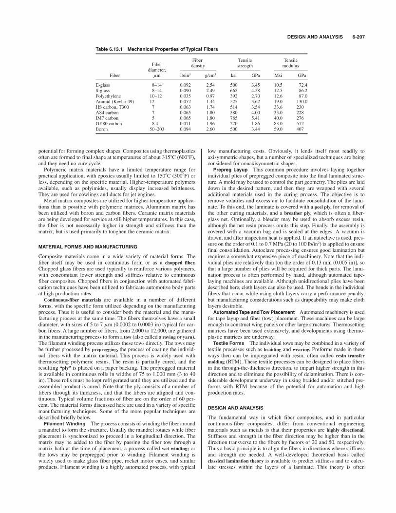
DESIGN AND ANALYSIS 6-207
potential for forming complex shapes. Composites using thermoplasticsoften are formed to final shape at temperatures of about 315*C (600*F),and they need no cure cycle.Polymeric matrix materials have a limited temperature range for
practical application, with epoxies usually limited to 150*C (300*F) orless, depending on the specific material. Higher-temperature polymersavailable, such as polyimides, usually display increased brittleness.They are used for cowlings and ducts for jet engines.Metal matrix composites are utilized for higher-temperature applica-
tions than is possible with polymeric matrices. Aluminum matrix hasbeen utilized with boron and carbon fibers. Ceramic matrix materialsare being developed for service at still higher temperatures. In this case,the fiber is not necessarily higher in strength and stiffness than thematrix, but is used primarily to toughen the ceramic matrix.
MATERIAL FORMS AND MANUFACTURING
Composite materials come in a wide variety of material forms. Thefiber itself may be used in continuous form or as a chopped fiber.Chopped glass fibers are used typically to reinforce various polymers,with concomitant lower strength and stiffness relative to continuousfiber composites. Chopped fibers in conjunction with automated fabri-cation techniques have been utilized to fabricate automotive body partsat high production rates.Continuous-fiber materials are available in a number of different
forms, with the specific form utilized depending on the manufacturingprocess. Thus it is useful to consider both the material and the manu-facturing process at the same time. The fibers themselves have a smalldiameter, with sizes of 5 to 7 mm (0.0002 to 0.0003 in) typical for car-bon fibers. A large number of fibers, from 2,000 to 12,000, are gatheredin the manufacturing process to form a tow (also called a roving or yarn).The filament winding process utilizes these tows directly. The tows maybe further processed by prepregging, the process of coating the individ-ual fibers with the matrix material. This process is widely used withthermosetting polymeric resins. The resin is partially cured, and theresulting “ply” is placed on a paper backing. The prepregged materialis available in continuous rolls in widths of 75 to 1,000 mm (3 to 40in). These rolls must be kept refrigerated until they are utilized and theassembled product is cured. Note that the ply consists of a number offibers through its thickness, and that the fibers are aligned and con-tinuous. Typical volume fractions of fiber are on the order of 60 per-cent. The material forms discussed here are used in a variety of specificmanufacturing techniques. Some of the more popular techniques aredescribed briefly below.
Filament Winding The process consists of winding the fiber arounda mandrel to form the structure. Usually the mandrel rotates while fiberplacement is synchronized to proceed in a longitudinal direction. Thematrix may be added to the fiber by passing the fiber tow through amatrix bath at the time of placement, a process called wet winding; orthe tows may be prepregged prior to winding. Filament winding iswidely used to make glass fiber pipe, rocket motor cases, and similarproducts. Filament winding is a highly automated process, with typical
low manufacturing costs. Obviously, it lends itself most readily toaxisymmetric shapes, but a number of specialized techniques are beingconsidered for nonaxisymmetric shapes.
Prepreg Layup This common procedure involves laying togetherindividual plies of prepregged composite into the final laminated struc-ture. A mold may be used to control the part geometry. The plies are laiddown in the desired pattern, and then they are wrapped with severaladditional materials used in the curing process. The objective is toremove volatiles and excess air to facilitate consolidation of the lami-nate. To this end, the laminate is covered with a peel ply, for removal ofthe other curing materials, and a breather ply, which is often a fiber-glass net. Optionally, a bleeder may be used to absorb excess resin,although the net resin process omits this step. Finally, the assembly iscovered with a vacuum bag and is sealed at the edges. A vacuum isdrawn, and after inspection heat is applied. If an autoclave is used, pres-sure on the order of 0.1 to 0.7 MPa (20 to 100 lb/in2) is applied to ensurefinal consolidation. Autoclave processing ensures good lamination butrequires a somewhat expensive piece of machinery. Note that the indi-vidual plies are relatively thin [on the order of 0.13 mm (0.005 in)], sothat a large number of plies will be required for thick parts. The lami-nation process is often performed by hand, although automated tape-laying machines are available. Although unidirectional plies have beendescribed here, cloth layers can also be used. The bends in the individualfibers that occur while using cloth layers carry a performance penalty,but manufacturing considerations such as drapeability may make clothlayers desirable.
Automated Tape and Tow Placement Automated machinery is usedfor tape layup and fiber (tow) placement. These machines can be largeenough to construct wing panels or other large structures. Thermosettingmatrices have been used extensively, and developments using thermo-plastic matrices are underway.
Textile Forms The individual tows may be combined in a variety oftextile processes such as braiding and weaving. Preforms made in theseways then can be impregnated with resin, often called resin transfermolding (RTM). These textile processes can be designed to place fibersin the through-the-thickness direction, to impart higher strength in thisdirection and to eliminate the possibility of delamination. There is con-siderable development underway in using braided and/or stitched pre-forms with RTM because of the potential for automation and highproduction rates.
DESIGN AND ANALYSIS
The fundamental way in which fiber composites, and in particularcontinuous-fiber composites, differ from conventional engineeringmaterials such as metals is that their properties are highly directional.Stiffness and strength in the fiber direction may be higher than in thedirection transverse to the fibers by factors of 20 and 50, respectively.Thus a basic principle is to align the fibers in directions where stiffnessand strength are needed. A well-developed theoretical basis calledclassical lamination theory is available to predict stiffness and to calcu-late stresses within the layers of a laminate. This theory is often
Table 6.13.1 Mechanical Properties of Typical Fibers
Fiber Tensile TensileFiber density strength modulus
diameter,Fiber mm lb/in3 g/cm3 ksi GPa Msi GPa
E-glass 8–14 0.092 2.54 500 3.45 10.5 72.4S-glass 8–14 0.090 2.49 665 4.58 12.5 86.2Polyethylene 10–12 0.035 0.97 392 2.70 12.6 87.0Aramid (Kevlar 49) 12 0.052 1.44 525 3.62 19.0 130.0HS carbon, T300 7 0.063 1.74 514 3.54 33.6 230AS4 carbon 7 0.065 1.80 580 4.00 33.0 228IM7 carbon 5 0.065 1.80 785 5.41 40.0 276GY80 carbon 8.4 0.071 1.96 270 1.86 83.0 572Boron 50–203 0.094 2.60 500 3.44 59.0 407

applied to filamentwound structures and to textile preform structures, ifallowances are made for the undulations in the fiber path. The basicassumption is that fiber composites are orthotropic materials. Thincomposite layers require four independent elasticity constants to char-acterize the stiffness; those are the fiber direction modulus, transversedirection modulus, in-plane shear modulus, and one of the two Poissonratios, with the other related through symmetry of the orthotropic stress-strain matrix. The material constants are routinely provided by materialsuppliers. Lamination theory is then used to predict the overall stiffnessof the laminate and to calculate stresses within the individual layersunder mechanical and thermal loads.Transverse properties are much lower than those in the fiber direc-
tion, so that fibers must usually be oriented in more than one direction,even if only to take care of secondary loads. For example, a laminatemay consist of fibers in an axial direction combined with fibers orientedat ,60* to this direction, commonly designated as an [0m/,60n]s lami-nate, where m and n refer to the number of plies in the axial and , 60*directions and s stands for symmetry with respect to the midplane ofthe laminate. Although not all laminates are designed to be symmetric,residual stresses will cause flat panels to curve when cooled fromelevated-temperature processing unless they are symmetric. Other pop-ular laminates have fibers oriented at 0*, ,45*, and 90*. If the relativeamounts of fibers are equal in the [0/,60] or the [0/,45/90] directions,the laminate has in-plane stiffness properties equal in all directions andis thus termed quasi-isotropic.Note that the stiffness of composite laminates is less than that of the
fibers themselves for two reasons. First, the individual plies containfibers and often a much less stiff matrix. With high-stiffness fibers andpolymeric matrices, the contribution of the matrix can be neglected, sothat the stiffness in the fiber direction is essentially the flber volumefraction VF times the fiber stiffness. Fiber volume fractions are often onthe order of 60 percent. Second, laminates contain fibers oriented in morethan one direction, so that the stiffness in any one direction is less thanit would be in the fiber direction of a unidirectional laminate. As an exam-ple, the in-plane stiffness of a quasi-isotropic carbon fiber/polymericmatrix laminate is about 45 percent of unidirectional plies, which inturn is approximately 60 percent of the fiber modulus for a 60 percentfiber volume fraction material.
Strength Properties Fiber composites typically have excellentstrength-to-weight properties; see Table 6.13.1. Like stiffness proper-ties, strength properties are reduced by dilution by the weaker matrix,
and because not all the fibers can be oriented in one direction. The over-all reduction in apparent strength because of these two factors is simi-lar to that for stiffness, although this is a very rough guide. As anexample, the strength of a quasi-isotropic carbon/epoxy laminate underuniaxial tensile load has been reported to be about 35 to 40 percent ofthat provided by the same material in a unidirectional form. Fiber composite materials can fail in several different modes. The
design goal is usually to have the failure mode be in-plane failure due tofiber failure, as this takes advantage of the strong fibers. Unanticipatedloads, or poorly designed laminates, can lead to ultimate failure of thematrix, which is much weaker. For example, in-plane shear loads on a[0/90] layup would be resisted by the matrix, with the potential result offailure at low applied load. Adding [,45] fibers will resist this shearloading effectively.Fiber composites respond differently to compressive loads than they do
to tensile loads. Some fibers, such as aramid and the very high-moduluscarbon fibers, are inherently weaker in compression than in tension. Itis believed that this is not the case with intermediate-modulus carbonfibers, but even these fibers often display lower compressive strength.The mechanism is generally believed to involve bending or bucklingof the very small-diameter fibers against the support provided by thematrix.Matrix cracking usually occurs in the transverse plies of laminates
with polymeric matrices, often at an applied load less than half that forultimate fiber failure. This is caused by the lower failure strain of thematrix and the stress concentration effect of the fibers, and it can alsodepend on residual thermal stresses caused by the differences in coeffi-cients of thermal expansion in the fibers and matrix. In some cases thesematrix cracks are tolerated, while in other cases they produce undesir-able effects. An example of the latter is that matrix cracking increasesthe permeability in unlined pressure vessels, which can result in pipesweeping.Another potential failure mode is delamination. Delamination is often
caused by high interlaminar shear and through-the-thickness tensilestresses, perhaps combined with manufacturing deficiencies such asinadequate cure or matrix porosity. Delamination can start at the edgesof laminates due to “edge stresses” which have no counterpart inisotropic materials such as metals.Fiber composites usually have excellent fatigue properties. However,
stress concentrations or accidental damage can result in localized dam-age areas that can lead to failure under fatigue loading.
6-208 FIBER COMPOSITE MATERIALS