section04 rev c - nasa · section04 rev c.doc 4-1 4. sounder the sounder, gfe manufactured by itt...
TRANSCRIPT

PM-1.1-03 Rev C February 2009
Section04 REV C.doc 4-1
4. Sounder
The Sounder, GFE manufactured by ITT Industries, Inc., is a 19 channel discrete-filter radiometer that senses specific data parameters for atmospheric vertical temperature and moisture profiles, surface and cloud top temperature, and ozone distribution. As in the Imager, the Sounder is capable of providing full earth imagery, sector imagery (including earth’s disk), and scans of local regions. The 19 spectral bands (seven longwave [LW], five midwave [MW], six shortwave [SW], and one visible) produce the prime sounding products. A cutaway view of the instrument is shown in Figure 4-1. Key instrument parameters are given in Tables 4-1 and 4-2. The wavelength allocation to the Sounder’s channels is given in Table 4-3. A summary of Sounder performance is given in Table 4-4.

PM-1.1-03 Rev C February 2009
4. Sounder
4-2 Section04 REV C.doc
Figure 4-1. Sounder Sensor Module
Table 4-1. Sounder Instrument Detectors and Fields of View
Channels Detector Type Nominal Circular IGFOV, μrad
1 to 7 (LW IR) HgCdTe 242
8 to 12 (MW IR) HgCdTe 242
13 to 18 (SW IR) InSb 242
19 (visible) Silicon 242
Star sense Silicon 28*
* Square detectors
Table 4-2. Sounder Instrument Performance Parameters
Parameter Performance
FOV defining element Field stop
Telescope aperture 31.1 cm (12.2 in) diameter
Channel definition Interference filters
Radiometric calibration Space and 300 K IR blackbody
Field sampling Four areas N-S on 280 μrad centers
Scan step angle 280 μrad (10 km nadir) EW
Step and dwell time 0.1, 0.2, 0.4 sec adjustable
Scan capability Full earth and space
Sounding areas 10 km by 40 km to 60° N-S and 60° E-W
Signal quantizing 13 bits, all channels
Output data rate 40 kbps
Channel-to-channel alignment 22 or 36 μrad with respect to channel 8, depending on the channel
The Sounder instrument consists of sensor, electronics, and power supply modules. The sensor module contains the telescope, scan assembly, and detectors, all mounted on a baseplate with shields and louvers for radiation and heat control. The sensor module is located on the nadir face of the spacecraft. The electronics module provides redundant circuitry and performs command, control, and signal processing functions and also serves as a structure for mounting and interconnecting the electronic boards for proper heat dissipation. The electronics module is mounted on the subnadir panel, external to the spacecraft and is enclosed by a Faraday cage. (The Faraday cage is fabricated from thermal blankets.) The power supply module contains the DC/DC converters, fuses, and power control for converting and distributing spacecraft bus power to the Sounder circuits. The power supply module is mounted inside the spacecraft on the subnadir panel.

PM-1.1-03 Rev C February 2009
4. Sounder
Section04 REV C.doc 4-3
Table 4-3. Sounder Detectors Channel Allocation
Detector
Channel No.
Wavelength, μm
Wave No., cm-1
Meteorological Objective and Max. Temp. Range
Longwave 1 14.71 680 Temperature Sounding (space–260 K) 2 14.37 696 Temperature Sounding (space–260 K) 3 14.06 711 Temperature Sounding (space–270 K) 4 13.64 733 Temperature Sounding (space–290 K) 5 13.37 748 Temperature Sounding (space–300 K) 6 12.66 790 Temperature Sounding (space–315 K) 7 12.02 832 Surface Temperature (space–330 K)
Midwave 8 11.03 907 Surface temperature (space–335 K) 9 9.71 1030 Total Ozone (space–310 K) 10 7.43 1345 Water Vapor Sounding (space–300 K) 11 7.02 1425 Water Vapor Sounding (space–285 K) 12 6.51 1535 Water Vapor Sounding (space–265 K)
Shortwave 13 4.57 2188 Temperature Sounding (space–310 K) 14 4.52 2210 Temperature Sounding (space–295 K) 15 4.45 2245 Temperature Sounding (space–275 K) 16 4.13 2420 Temperature Sounding (space–330 K) 17 3.98 2513 Surface Temperature (space–335 K) 18 3.74 2671 Surface Temperature (space–335 K)
Visible 19 0.70 14367 Cloud (visible)
Note: All channels have sufficient dynamic range to view the internal blackbody calibration target at 320 K.
The Sounder’s multidetector array simultaneously samples four locations of the atmos-phere in 0.1 second intervals (0.2 and 0.4 second dwells at the same FOV are also com-mandable). Each field of view (FOV) provides output from 19 spectral channels in each sample period. Infrared (IR) spectral definition is provided by a rotating wheel that inserts selected filters into the optical path of the detector assembly; the filters are arranged in three concentric spectral bands on the wheel. The filter wheel rotates continuously at 10 Hz, and its rotation is synchronized with the stepping motion of the scan mirror.
A user may request by command a set of soundings that start at a selected latitude and longitude and end at another latitude and longitude. The Sounder responds to scan locations that correspond to those command inputs. The sounding frame may include the whole or any portion of the earth and the frame may begin at any time. The Sounder scan control is not limited in scan size or time; thus an entire viewing angle of 21° north-to-south by 23° east-to-west is available for star location or sounding frames. Requests for up to 16 repeats of a given location can be made by ground command. Capability is provided for interrupting a frame sequence for “priority” scans. The system will scan a priority frame set or star sense, then automatically return to the original set.

PM-1.1-03 Rev C February 2009
4. Sounder
4-4 Section04 REV C.doc
Table 4-4. Sounder Instrument Performance Summary
Parameter Performance
System absolute accuracy Infrared channel ≤1 K
Visible channel ±5% of max scene radiance
System relative accuracy Line to line Detector to detector Channel to channel Blackbody calibration to
calibration
≤0.25 K
≤0.40 K
≤0.29 K
≤0.60 K
Star sense area 21° N-S by 23° E-W
Sounding rate 3000 by 3000 km ≤42 min
Time delay ≤3 min
Data timeliness Spacecraft processing ≤30 sec
Sounding periods
Image navigation accuracy at nadir(excluding diurnally repeatable distance)
30 μrad
Registration within 120 minute sounding
120 min 42 μrad
Registration between repeated soundings
24 hr 42 μrad
Radiometric quality is maintained by frequent (every 2 minutes) views of space for reference. Less frequent views (20 minutes) of the full aperture internal blackbody establish a high temperature baseline for instrument calibration in orbit. Further, the amplifiers and data stream are checked for stability by an electronic staircase signal during each blackbody reference cycle. Other aspects of the Sounder are the same as for the Imager.
Operation The Sounder is controlled by a defined set of command inputs. The instrument is capa-ble of full earth sounding and sector sounding, including various sounding area sizes totally enclosed within the earth scene. Area scan size can be as small as one sounding location. The sounding dwell at each step is selectable to be 0.1, 0.2, or 0.4 second. An optional capability is provided for skipping scan lines to increase the rate of area sounding at a dwell time of 0.2 second per sounding.
The Sounder’s flexible operation includes a star sensing capability. Once the time and location of a star is predicted, the Sounder scanner is pointed to that location within its 21° N-S by 23° E-W field of view and the scan stopped. A separate linear array of eight

PM-1.1-03 Rev C February 2009
4. Sounder
Section04 REV C.doc 4-5
silicon detectors with a 240 µrad N-S coverage, similar to the Imager, is used. As the star image passes through the detectors, the signal is sampled, then encoded and included in each Sounder data block for extraction and use at the ground station. The star sense detectors are sampled at 40 times per second.
Duplication of the four element array in each of the three bands (longwave, 12 µm to 14.7 µm; midwave, 6.5 µm to 11 µm; and shortwave, 3.7 µm to 4.6 µm) yields the spectral separation of the infrared bands; the filters are arranged on the wheel for efficient use of sample time and optimal channel coregistration. Each detector converts the atmospheric radiance into an electrical signal that is amplified, filtered, and digitized; the resulting digital signal is routed to a sensor data transmitter, for downlinking to a ground station.
By synchronizing filter wheel rotation with the scan mirror’s stepping motion, all sampling is accomplished with the mirror in a stopped condition. Upon ground com-mand, the scan system can generate frames of any size or location using west-to-east stepping and east-to-west stepping of 280 µrad, with a north-to-south step of 1120 µrad, continuing the pattern until the desired frame is completed. The visible channel (0.7 µm), not part of the filter wheel, is a separate set of uncooled detectors with the same field size and spacing. These detectors are sampled at the same time as the infrared channels (3, 11, and 18), providing registration of all sounding data.
By virtue of its digitally controlled scanner, the Sounder provides operational sounding from full earth scan to mesoscale area scans. Accuracy of location is provided by the absolute position control system in which position error is noncumulative. Within the instrument, each position is defined precisely and any chosen location can be reached and held to a high accuracy. This registration accuracy is maintained along a scan line, throughout an image and over time. Total system accuracies relating to spacecraft motion and attitude determination also include this allocated error.
Motion of the Imager and Sounder scan mirrors causes a small but well-defined distur-bance of spacecraft attitude. The disturbances caused by each scan motion on the spacecraft are easily calculated by the attitude control subsystem (ACS). A compensating signal is developed and applied in the scan servo-control loop to bias scanning and offset the disturbance. This simple signal and control interface provides corrections that minimize any combination of effects. With this technique, the Imager and Sounder are totally independent, maintaining image location accuracy regardless of the other unit’s operational status. If needed, this mirror motion compensation scheme can be disabled by command.
The ACS also provides compensation signals that counteract spacecraft attitude, orbital effects, and predictable structural-thermal effects within the spacecraft-instrument combination. These disturbances are detected from star sensing and land features. Ground-developed corrective algorithms are fed to the instruments via the ACS as a total image motion compensation (IMC) signal that includes the dynamic mirror motion compensation described above.

PM-1.1-03 Rev C February 2009
4. Sounder
4-6 Section04 REV C.doc
Yaw Flip Operation There is an alternative spacecraft orientation option for the GOES-NOP satellites known as the yaw flip configuration. In this mode, the satellite is rotated 180 degrees from its normal orientation, and results in the normally north facing side of the instruments facing toward the south during summer in the northern hemisphere. Yaw flip maintains the spacecraft in a configuration that prevents the sun from entering the radiant coolers.
This mode allows operation of the instruments with the patch temperature set to LOW year round as the radiant coolers are always pointing in a direction that permits operat-ing under winter conditions. Without yaw flip, the patch temperature settings should be LOW for winter and MID for summer. MID can be used year round without yaw flip if there is no cooler degradation as the cooler should start life with a 3° C margin at the MID setting for summer solstice. HIGH allows for operation in the summer should some cooler degradation occur.
It should be noted that all references to the scan coordinate system will be reversed when operating in the yaw flipped mode.
Sensor Module The sensor module consists of a louver assembly, baseplate, scan assembly, scan aperture sun shield, preamplifiers, telescope, aft optics, filter wheel, and radiant cooler assemblies for the detectors and the filter wheel. The scan assembly and telescope are mounted on a common baseplate. A passive louver assembly and electrical heaters on the base aid thermal stability of the telescope and major components. A passive radiant cooler with a proportionally controlled heater maintains the infrared detectors at 82 K during the winter solstice season and 85 K for the remaining portion of the year (with 88 K as backup). The visible and star sense detectors are at instrument temperature of 13 to 30°C. Preamplifiers in the sensor module convert the low-level signals to higher level, low impedance outputs for transmission by cable to the electronics module. Figure 4-2 illustrates an expanded view of the sensor module.

PM-1.1-03 Rev C February 2009
4. Sounder
Section04 REV C.doc 4-7
Figure 4-2. Sensor Module – Expanded View
Sounder Optics The Sounder telescope is similar to that of the Imager. Dichroic beamsplitters separate the scene radiance into the spectral bands of interest. The IR energy is deflected toward the detectors located on the coldest stage of the radiative cooler, while the visible energy passes through a dichroic beamsplitter and is focused on the visible (sounding and star) detector elements. The SW and MW bands are reflected by another dichroic beamsplitter and the LW is transmitted through it. Optical separation of the 18 IR channels takes place at the filter wheel assembly. Figure 4-3 illustrates the Sounder optical elements.
Filter Wheel The filter wheel is a 28.2 centimeter (11.1 inch) diameter disk containing 18 filter windows divided into three concentric rings, one ring for each IR detector group. The outer ring contains seven LW channels, the middle ring contains six SW channels, and the inner ring contains five MW channels. Filter angular lengths are selected to provide nearly equal performance margin in each channel. The wheel has approximately one-

PM-1.1-03 Rev C February 2009
4. Sounder
4-8 Section04 REV C.doc
Figure 4-3. Sounder Optical Elements
fourth of its area clear of filters. By synchronizing the stepping of the scan mirror to occur in this “dead zone,” the wheel can continue rotating while the mirror steps to the next location and is stopped while the 18 channels are sampled. Stopping the mirror ensures that all channels sample the same column of the atmosphere; holding and sampling in 0.075 second provides virtually simultaneous sampling of the channels. Figure 4-4 illustrates the filter wheel configuration.

PM-1.1-03 Rev C February 2009
4. Sounder
Section04 REV C.doc 4-9
Figure 4-4. Filter Wheel and Channel Separation
The first channels to be sampled are high altitude sensors that have little spatial defini-tion and are less affected by the settling characteristics of the scan mirror. The earth sur-face viewing channels are grouped near the end of the sounding period for maximum stability and coregistration. Though not viewed through the filter wheel, the visible detectors are gated so that they sample the same atmospheric column at the same time as the IR channels.
The filter wheel acts as the spectral defining element in the optics, though it also has a major effect on radiometric stability and signal quality. Each filter has a very narrow spectral bandpass, restricting the radiant input from the scene and contributions from optical parts in the path to the filter wheel. From filter wheel to detectors, there is no spectral limit other than a broadband limiting filter in the cooler. Any small deviation of radiance in this area may cause unwanted noise in the signal. To reduce emitted energy that might cause random noise and to provide very low background radiance input to the detectors, the filter wheel is cooled to approximately 212 K. The temperature of the filter wheel housing is brought to 210 K by thermal connection to a radiating surface. Heaters and a precision temperature control circuit maintains the housing within 1°C of the set temperature.

PM-1.1-03 Rev C February 2009
4. Sounder
4-10 Section04 REV C.doc
Detectors The Sounder acquires radiometric data for 19 distinct wavelengths or channels through the use of four separate detector assemblies and a rotating filter wheel. This generates an 1120 µrad N-S swath that is moved latitudinally in 280 µrad (10 km) steps. A fifth detector array provides the Sounder with star sense capabilities. Each of the radiometric channels is characterized by a central wavelength denoting primary spectral sensitivity. The 19 channels are broadly split into two classes: visible (channel 19) and infrared (channels 1-18). Figure 4-5 illustrates the detector array arrangement.
Visible Channel The visible silicon detector array (channel 19) contains four detectors, each with an instantaneous geometric field of view (IGFOV) of 242 µrad in diameter set by the detectors size, corresponding to an 8.7 km (28 μrad) diameter nominal pixel size at the spacecraft suborbital point. A star sensing array, consisting of a separate set of eight silicon detectors, is on the same mount and aligned to the center of the visible sounding detectors. It is identical to the Imager visible detector array but has 0.97 km (0.60 statute mile) resolution and 8.5 km (5.3 statute mile) array coverage.
Infrared Channels The IR channels (1 through 18) are contained in three detector sets: LW, MW, and SW, each set consisting of four detectors. The fields of view are set by the field stops in a pattern the same as the visible channel.
Figure 4-5. IR, Visible, and Star Sense Detector Arrays

PM-1.1-03 Rev C February 2009
4. Sounder
Section04 REV C.doc 4-11
Element Configuration Each of the field stop or detector patterns is arranged in the same asymmetric fashion, with a nominal focal plane configuration. The star sensing array and visible radiometric array have a clear optical path in the instrument. The three arrays dedicated to IR wavelengths (LW, MW, and SW) are optically located behind the filter wheel assembly, each handling a different region of the infrared spectrum. Although physically sepa-rated in the instrument, the four radiometric arrays are coregistered optically, resulting in automatic coalignment of the pixels for all 19 channels. Figure 4-6 illustrates the detector separation and scan pattern.
Scan Control As in the Imager, the Sounder scans the selected image area in alternate lines (that is, west-to-east followed by east-to-west or vice versa) and is capable of scanning both north-to-south and south-to-north. The scanning mirror position is controlled by two servo motors, one for the N-S gimbal angle and one for the E-W scanning gimbal angle. Each servo motor has an associated Inductosyn that measures the mechanical shaft rotation angle. The scanning mirror position and, hence, the coordinate system used for the Sounder are measured in terms of Inductosyn outputs. Scan control for both axes is generated by establishing a desired angular position for the mirror. The desired angle is input to an angular position sensor (one Inductosyn for each axis), which produces a displacement error signal. This signal is fed to a direct drive torque motor (one for each axis) that moves the mirror and sensor to the null location. Figure 4-7 illustrates the scan control block diagram.
For E-W deflection, the direct-drive torque motor is mounted to one side of the scan mirror and the position-sensing device (Inductosyn position encoder) is mounted on the opposite side. All rotating parts are on a single shaft with a common set of bearings. Using components of intrinsically high resolution and reliability, coupling of the drive, motion, and sensing is therefore very tight and precise. North-south motion is provided by rotating the gimbal (holding the above components) about the optical axis of the tele-scope. This rotating shaft has the rotary parts of another torque motor and Inductosyn mounted to it, again providing the tight control necessary.
The servo system is not absolutely accurate because of noise, drag, bearing imperfec-tions, misalignment, and imperfections in the Inductosyn. Such inherent position-related errors cause pointing errors that preclude achieving the highest possible system accu-racy. Slight variations of individual pole pairs cause a systematic pattern that is repeat-able and measurable and can therefore be stored and subtracted to counteract the Inductosyn’s inherent error. This fixed error pattern and other systematic factors are measured, encoded, and stored in read-only memory. By injecting this stored error sig-nal into the main control loop, the effect of Inductosyn electromechanical errors and other systematic effects are reduced to less than one-fourth of their noncorrected values.

PM-1.1-03 Rev C February 2009
4. Sounder
4-12 Section04 REV C.doc
Figure 4-8. Detector Separation and Scan Pattern

PM-1.1-03 Rev C February 2009
4. Sounder
Section04 REV C.doc 4-13
Figure 4-7. Scan Control Schematic

PM-1.1-03 Rev C February 2009
4. Sounder
4-14 Section04 REV C.doc
Drive and error sensing components used for the two drive axes are essentially identical. Control components are optimized for their frequency and control characteristics, and logic is developed for the precise control of position in response to a system-level control processor.
Scan Operation Scan control is initiated by input commands that set start and end locations of a sound-ing frame. A location is identified by an Inductosyn cycle and increment number within that cycle, the increment number determining the value of sine and cosine for that loca-tion. Each E-W increment corresponds to 17.5 µrad of E-W mechanical rotation or 35 µrad of E-W optical rotation. Each N-S increment corresponds to 17.5 µrad of N-S mechanical and optical rotation. The distance between a present and start location is recognized, causing incremental steps (17.5 µrad) at a high rate (10 deg/sec) to reach that location. To minimize peak power demand the scan slews latitudinally, then longi-tudinally to a requested location.
Scan to space for space clamp or to star sensing, or to the IR blackbody uses the slew function. Command inputs (for star sensing or priority scan) or internal subprograms (for space clamp and IR calibration) take place at the proper time during a frame.
Sounding Generation The E-W scan of the Sounder is acquired via a repeating sample-step-settle sequence that constitutes a 100 ms (single dwell), 200 ms (double dwell), or 400 ms (quadruple dwell) intervals. This is controlled by the filter wheel rotation. This step-settle sequence repeats until the end of the scan line is reached. At this point, a 100 ms interval is executed in which the mirror will be stepped 1120 µrad (40 kilometers at the spacecraft subsatellite point) in the N-S direction, which is four times larger than the E-W scan step. At the conclusion of this interval, acquisition of the next scan line will be initiated in the oppo-site E-W direction using the sample-step-settle sequence. In the double (quadruple) dwell mode, two (four) detector samples are acquired at each step.
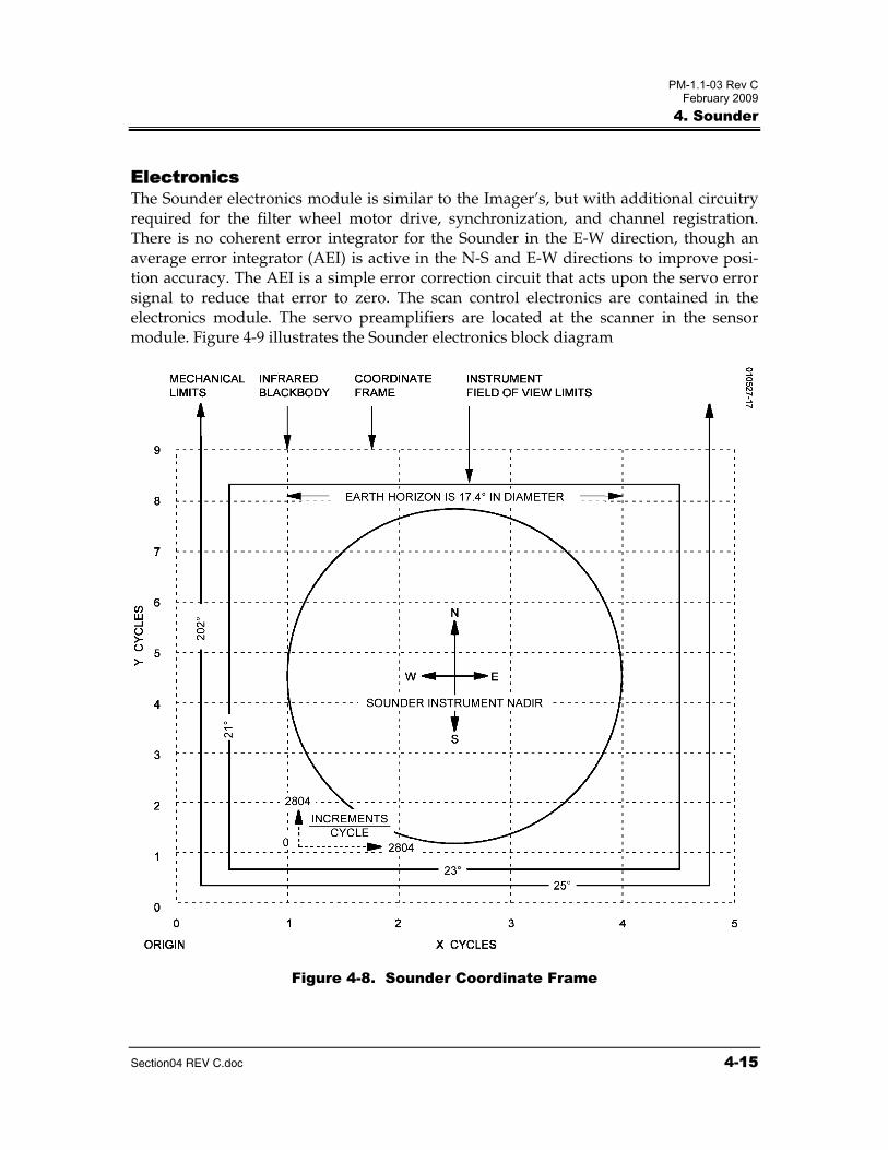
The mapping between cycles and increments and the instrument field of view are refer-enced to a coordinate frame whose origin is zero cycles and zero increments (southwest corner of the frame). In geostationary orbit, the earth will be centered within the frame, at instrument nadir, which corresponds closely to the spacecraft subsatellite point, also centered in the frame. The GVAR coordinate system for both the Imager and Sounder is in line/pixel space and has its origin in the NW corner. The Sounder's coordinate system frame is shown in Figure 4-8, showing the earth disc centered in the instrument 's coordinate frame, the 21°x23° operational FOV limit frame and the 25°x202° mechanical limit frame. The earth disc subtends a 17.4° viewing angle from geostationary altitude.
PM-1.1-03 Rev C February 2009
4. Sounder
Section04 REV C.doc 4-15
Electronics The Sounder electronics module is similar to the Imager’s, but with additional circuitry required for the filter wheel motor drive, synchronization, and channel registration. There is no coherent error integrator for the Sounder in the E-W direction, though an average error integrator (AEI) is active in the N-S and E-W directions to improve posi-tion accuracy. The AEI is a simple error correction circuit that acts upon the servo error signal to reduce that error to zero. The scan control electronics are contained in the electronics module. The servo preamplifiers are located at the scanner in the sensor module. Figure 4-9 illustrates the Sounder electronics block diagram
Figure 4-8. Sounder Coordinate Frame

PM-1.1-03 Rev C February 2009
4. Sounder
4-16 Section04 REV C.doc
Signal Processing Preamplification of the low-level IR and visible channel signals occurs within the sensor module. These analog signals are sent to the electronics module, which amplifies, filters, and converts the signals to digital code. All channels in the visible and IR bands are dig-itized to one part in 8192 (13 bits), the visible for high-quality visible sensing, and the IR for radiometric measurement. The data from the star sensing channel is also digitized to 13 bits. Data from all channels move in continuous streams throughout the system; thus each channel’s output must enter a short-term memory for proper formatting in the data stream. Each channel is composed of a detector, preamplifier, filter, postamplifier, analog-to-digital converter, and signal buffer. All signal chains are totally independent and isolated. Redundant chains of signal processing circuitry are provided with each circuit ending in a line driver designed to interface with the spacecraft sensor data transmitter.
Electronic Calibration Electronic calibration signals are injected into the preamplifier of all channels while the Sounder is looking at space. Sixteen precise signal levels derived from a stepped digital-to-analog (D/A) converter are inserted during the 0.2 second spacelook. The electronic calibration signal is derived from a 10 bit converter having 0.5 bit accuracy, providing the accuracy and linearity for precise calibration. This is inserted into all preamplifiers of all channels, both visible and IR.
Visible Channels The visible channel and star sensing detector arrays have a separate amplifier/processor for each detector element. These preamplifiers are current sensing types that convert the photon-generated current in the high impedance silicon detector into an output voltage, with a gain of about 108 V/A. The preamplifiers are followed by postamplifiers that contain electrical filtering and space clamping circuits. The digitization of the data sig-nals is also part of the space clamp circuitry. The visible information is converted to 13 bit digital form, providing a range from near 0.1% to over 100% albedo for the visible channel. Differences of approximately 0.1% are discernible, and the linear digitization provides for system linearity errors of 0.5 bit in the conversion process.
Infrared Channels The IR channels have a separate amplifier/processor for each detector element. Individ-ual amplifiers for each detector are mounted near the detectors in the sensor module. The shortwave channel detectors (ch 13 to 18) have the first stage of the preamplifiers incorporated into the detector packages.
The IR information is converted to 13 bit digital form, providing a range from near 0.1% to over 100% of the response range. Each channel has a gain established for space-to-scene temperatures of 260 to 335 K. The 13 bit digital form allows the lowest calculated noise level to be differentiated. The digital system is inherently linear with analog-to-digital (A/D) converter linearity and accuracy to 0.5 bit. The binary coded video is strobed onto the common data bus for data formatting by the system timing and control circuitry.

PM-1.1-03 Rev C February 2009
4. Sounder
4-17 Section04 REV C.doc
Figure 4-9. Sounder Electronic Block Diagram

PM-1.1-03 Rev C February 2009
4. Sounder
4-18 Section04 REV C.doc
Formatting Digital signal processing starts where data streams from the IR and visible detectors and telemetry merge via multiplexing (a parallel-to-serial conversion and data multiplexing take place to bring sensor data together). Other information, such as synchronization pulses, scan location, and telemetry data, are assembled in the data select circuitry. The data are then passed through a line driver where pulse amplitude and impedance levels are set for the transmitter interface.
A Sounder data block is transmitted during the time it takes for the filter wheel to complete one revolution (0.1 second). Unlike the Imager, there is no concept of multiple data block types that are formatted differently as a function of their data content. All of the data is contained in a stream of Sounder data blocks of one type, where each data block contains 250 16 bit words transmitted at a data rate of 40 kbps or 10 blocks per second. A Sounder data block contains:
• Sounding data
• Star sense data
• Telemetry
• Header data
• Synchronization
• Spacecraft attitude data
• Scan position
• Scan control data
Power Supply The block diagram of the Sounder power supply system is similar to that given for the Imager with the exception that the Sounder power supply contains two additional DC/DC converters to provide power for the filter wheel. The power supply converts spacecraft main bus voltage (42 volts nominal) to the required instrument voltages. There are two sides (1 and 2) to the unit, each totally independent and selected by com-mand, although only one side operates at a time.
The power supply provides secondary power for the instrument by means of eight DC/DC switching mode converters. Each redundant side of the instrument has four separate converters that supply power to 1) the telemetry circuits, 2) the scanner drive circuits, 3) the filter wheel drive circuits, and 4) the remainder of the instrument elec-tronics. The converters consist of synchronized switching circuits, transformers, rectifi-ers, and filters. The telemetry, electronics, and filter wheel supplies feed regulators to provide regulated voltage levels to the appropriate analog and logic circuits. The scan converter supplies power to the scan motor drive circuits and feeds a regulator to pro-vide regulated voltage levels to scan control circuits. The converters are synchronized to

PM-1.1-03 Rev C February 2009
4. Sounder
Section04 REV C.doc 4-19
200 kHz and the Electronics and Scan converters use a push-pull topology while the Telemetry and Filter Wheel converters use a flyback configuration. A diode OR’ing circuit permits operation of all nonredundant circuits (patch temperature control, video amplifiers, etc.) by either side. Control of the power supplies is achieved using relays for turn on, turn off, and side select. Ultimate protection for the spacecraft power bus is provided by having fuses on the input lines of the power supply.

PM-1.1-03 Rev C February 2009
4. Sounder
4-20 Section04 REV C.doc
This page left blank.