sectional truck scale installation guide · the m2000 digital system provides state of the art...
TRANSCRIPT
DIGITAL WEIGHING SYSTEM
SECTIONAL TRUCK SCALE INSTALLATION GUIDE
FOR SOFTWARE VERSION 1.21 (MAY 2003)
M2000 DIGITAL WEIGHING SYSTEM SECTIONAL TRUCK SCALE INSTALLATION GUIDE Copyright © 2003 Western Scale Company Limited. All rights reserved. Published by: WESTERN SCALE CO. LTD. 1670 Kingsway avenue Port Coquitlam, B.C. Canada V3C 3Y9 Information in this Installation Guide is subject to change without notice due to correction or enhancement. The information described in this manual is the property of Western Scale. No part of this manual may be reproduced or transmitted in any form, without the express written permission of Western Scale. Western Scale Locations Western Scale Co. Ltd. 1670 Kingsway Avenue Port Coquitlam, B.C. Canada V3C 3Y9 www.westernscale.ca [email protected] Wescale Inc. DIVISION OF WESTERN SCALE 3873 Airport Way Bellingham, WA. USA 98227 - 9754 www.wescale.com [email protected] FOR TECHNICAL SUPPORT REGARDING THIS PRODUCT, PLEASE CALL:
1-604-941-3474

TABLE OF CONTENTS Introduction…………………………………………………………………………………. 1 Installation Strategies…………………………………………………………….. 2 System Grounding……………………………………………………………….. 3 Getting Started…………………………………………………………………………… 4 Setting the DLC ID Jumper……………………………………………………… 5 Wiring Loadcells to the DLC Smart Box………………………………………… 6 Wiring DLC Smart Boxes to the M2000D Indicator…………………………….. 7 Other Wiring to the M2000D Indicator………………………………………….. 9 Powering Up the Indicator for the First Time…………………………………… 10 LEDs on Power Up……………………………………………………………… 10 Calibration Mode……………………………………………………………………….. 11 Entering Into Calibration Mode…………………………………………………. 11
Entering Calibration Commands………………………………………………… 11 Setting Graduation Size…………………………………………………………. 12 Setting Scale Capacity………………………………………………………….. 12 Setting Calibration Units………………………………………………………… 12 Allocating Sections……………………………………………………………… 13 Deadloading the Scale…………………………………………………………… 13 Spanning a Scale with a Test Weight…………………………………………… 14 Exit Calibration Mode…………………………………………………………… 14
Navigating the M2000………………………………………………………………….. 15 Select a Section or Cell…………………………………………………………. 16 Quick Select Method (For Sections)…………………………………………….. 17 Sectional Adjustment……………………………………………………………. 17 Example…………………………………………………………………. 18 Corner & Side-to-Side Adjustments…………………………………………….. 18 Serial Communications………………………………………………………………….. 19 Data Bits…………………………………………………………………………. 19 Baud Rate……………………………………………………………………….. 19 Parity…………………………………………………………………………….. 20 String Formats for Continuous Output………………………………………….. 20 Serial Handshaking……………………………………………………………… 21 Com Port String Output Mode…………………………………………………... 21 Configuring Com Ports to Transmit in RS422 Mode…………………………… 21 Transmission Delay for Com1 & Com2………………………………………… 22 M2000D System Specifications…………………………………………………………. 23 Appendix A - M2000 Parameters……………………………………………………….. 24 Appendix B - M2000D Specific Parameters……………………………………………. 26 Appendix C – Error Messages………………………………………………………….. 27


DIGITAL WEIGHING SYSTEM
1
INTRODUCTION
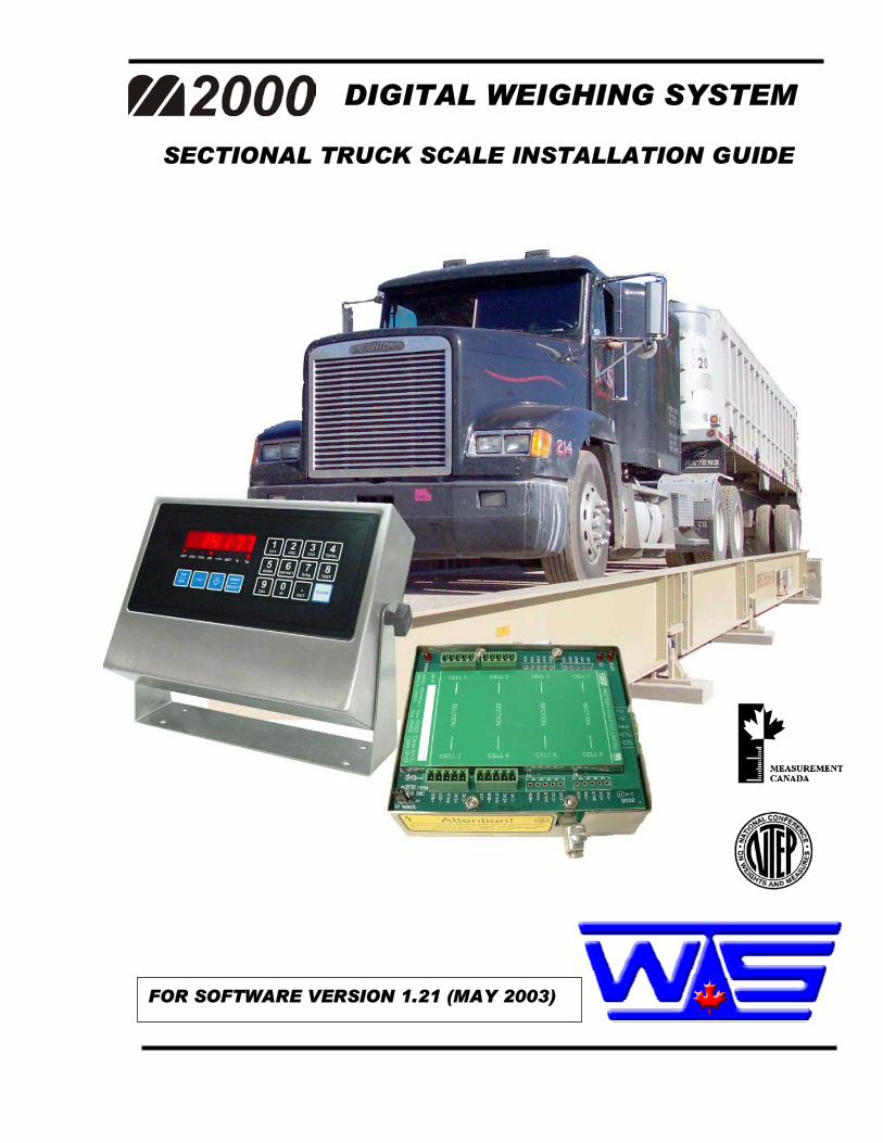
The M2000D Digital Smart Weigh System utilizes Digital Load Cell (DLC) technology to provide high-level data integrity, easier maintenance, and lightning protection for your weighing applications. Load cell connections to the DLC Smart Box (mounted on the weighbridge) are the same as connections to traditional analog summation cards. There are no pots to adjust and all sectional adjustments are made digitally through the keypad on the M2000D indicator. Each DLC Smart Box is available with 4, 6, or 8 load cell channels (inputs). The M2000D indicator can support up to 2 DLC Smart Boxes for a maximum of 16 load cells (8 Sections) per scale system. DLC Smart Boxes communicate with the indicator digitally through a current loop interface, resulting in no data degradation for up to 1000 feet. The cable link between the M2000D indicator and the DLC Smart Box is optically isolated and contains surge suppression devices to help protect the scale from lightning damage.
DLC SMART BOX
2
SECTIONAL TRUCK SCALE INSTALLATION GUIDE
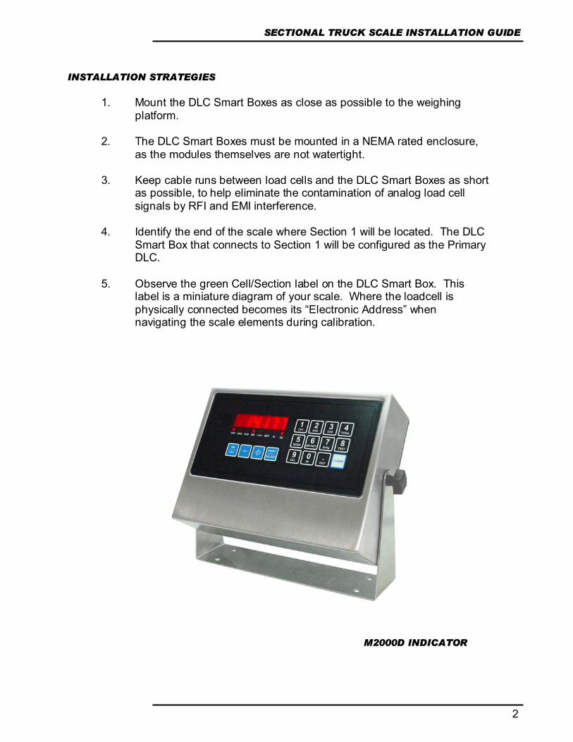
INSTALLATION STRATEGIES
1. Mount the DLC Smart Boxes as close as possible to the weighing
platform. 2. The DLC Smart Boxes must be mounted in a NEMA rated enclosure,
as the modules themselves are not watertight.
3. Keep cable runs between load cells and the DLC Smart Boxes as short as possible, to help eliminate the contamination of analog load cell signals by RFI and EMI interference.
4. Identify the end of the scale where Section 1 will be located. The DLC
Smart Box that connects to Section 1 will be configured as the Primary DLC.
5. Observe the green Cell/Section label on the DLC Smart Box. This
label is a miniature diagram of your scale. Where the loadcell is physically connected becomes its “Electronic Address” when navigating the scale elements during calibration.
M2000D INDICATOR
DIGITAL WEIGHING SYSTEM
3
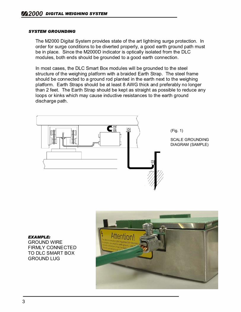
SYSTEM GROUNDING
The M2000 Digital System provides state of the art lightning surge protection. In order for surge conditions to be diverted properly, a good earth ground path must be in place. Since the M2000D indicator is optically isolated from the DLC modules, both ends should be grounded to a good earth connection. In most cases, the DLC Smart Box modules will be grounded to the steel structure of the weighing platform with a braided Earth Strap. The steel frame should be connected to a ground rod planted in the earth next to the weighing platform. Earth Straps should be at least 8 AWG thick and preferably no longer than 2 feet. The Earth Strap should be kept as straight as possible to reduce any loops or kinks which may cause inductive resistances to the earth ground discharge path.
EXAMPLE: GROUND WIRE FIRMLY CONNECTED TO DLC SMART BOX GROUND LUG
(Fig. 1) SCALE GROUNDING DIAGRAM (SAMPLE)
4
SECTIONAL TRUCK SCALE INSTALLATION GUIDE
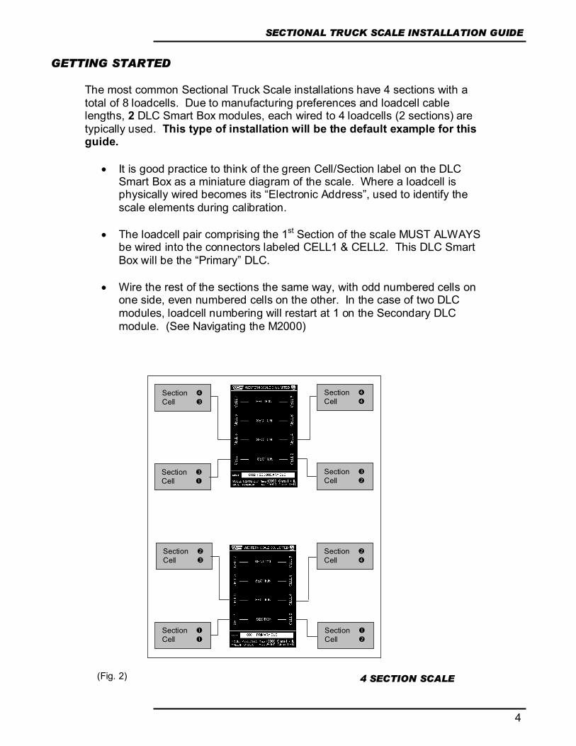
GETTING STARTED The most common Sectional Truck Scale installations have 4 sections with a total of 8 loadcells. Due to manufacturing preferences and loadcell cable lengths, 2 DLC Smart Box modules, each wired to 4 loadcells (2 sections) are typically used. This type of installation will be the default example for this guide.
• It is good practice to think of the green Cell/Section label on the DLC Smart Box as a miniature diagram of the scale. Where a loadcell is physically wired becomes its “Electronic Address”, used to identify the scale elements during calibration.
• The loadcell pair comprising the 1st Section of the scale MUST ALWAYS
be wired into the connectors labeled CELL1 & CELL2. This DLC Smart Box will be the “Primary” DLC.
• Wire the rest of the sections the same way, with odd numbered cells on
one side, even numbered cells on the other. In the case of two DLC modules, loadcell numbering will restart at 1 on the Secondary DLC module. (See Navigating the M2000)
Section Cell
Section Cell
Section Cell
Section Cell
Section Cell
Section Cell
Section Cell
Section Cell
4 SECTION SCALE (Fig. 2)

DIGITAL WEIGHING SYSTEM
5
SETTING THE DLC ID JUMPER When using two DLC Smart Boxes, the M2000D indicator needs to differentiate between the Primary and Secondary modules. An ID switch must be set via the ID jumpers in the bottom right hand corner of each module. For systems utilizing only one DLC Smart Box, the jumpers must be in the “Primary” position.
• It is extremely important to note which module is the PRIMARY DLC as it ALWAYS identifies the first section of the scale.
• There cannot be two primary (or two secondary) DLC Smart boxes.
Setting the switches properly is crucial for the system to function.
ID se
lect
JP 1
PRIM
SEC
ID se
lect
JP 1
PRIM
SEC JUMPER
THESE TWO PINS FOR PRIMARY DLC
JUMPER THESE TWO PINS FOR SECONDARY DLC
NOTE: If changing the DLC ID jumper after the initial scale setup, the indicator must be in Calibration Mode as jumper settings are stored with Calibration data.
(Fig. 3)
6
SECTIONAL TRUCK SCALE INSTALLATION GUIDE
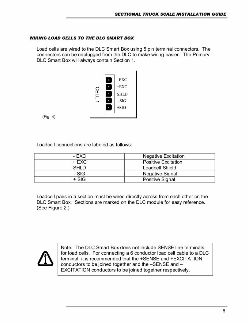
WIRING LOAD CELLS TO THE DLC SMART BOX Load cells are wired to the DLC Smart Box using 5 pin terminal connectors. The connectors can be unplugged from the DLC to make wiring easier. The Primary DLC Smart Box will always contain Section 1. Loadcell connections are labeled as follows:
- EXC Negative Excitation + EXC Positive Excitation SHLD Loadcell Shield - SIG Negative Signal + SIG Positive Signal
Loadcell pairs in a section must be wired directly across from each other on the DLC Smart Box. Sections are marked on the DLC module for easy reference. (See Figure 2.)
-EXC
+EXC
-SIG
+SIG
SHLD
CELL 1
Note: The DLC Smart Box does not include SENSE line terminals for load cells. For connecting a 6 conductor load cell cable to a DLC terminal, it is recommended that the +SENSE and +EXCITATION conductors to be joined together and the –SENSE and –EXCITATION conductors to be joined together respectively.
(Fig. 4)
DIGITAL WEIGHING SYSTEM
7
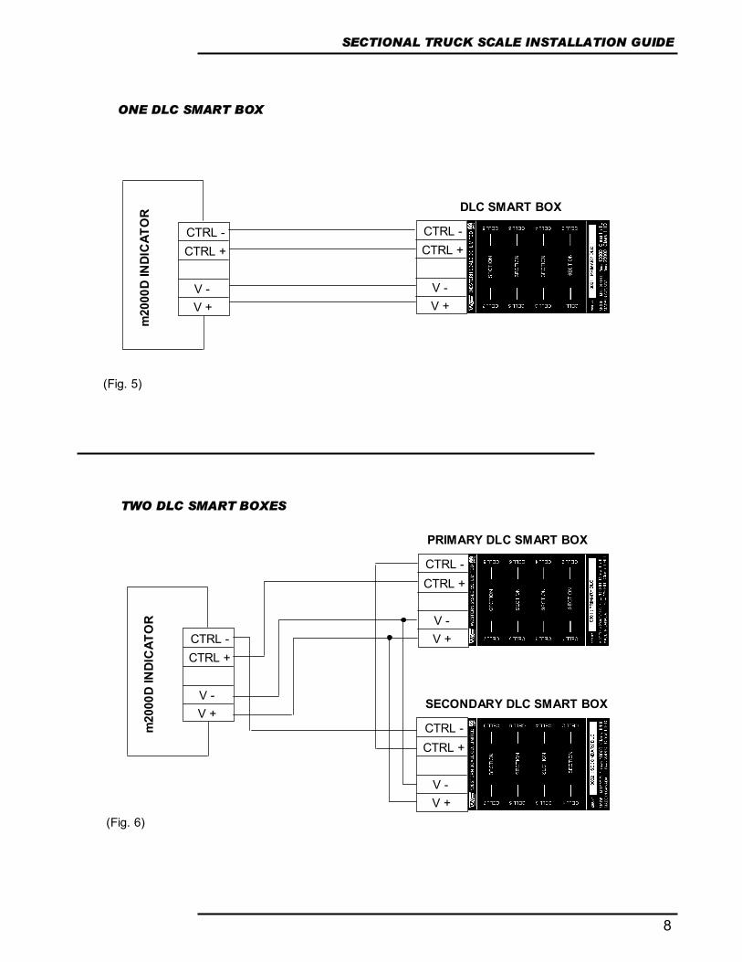
WIRING THE DLC SMART BOXES TO THE M2000D INDICATOR The scale wiring requires 2 pairs of shielded wire (one pair for power delivery and one pair for data communications) plus a separate shield conductor. The recommended cable type is Beldon 9873 20 AWG or equivalent. For cable runs over 100 feet, Beldon 9773 18 AWG or equivalent is recommended. The wires that connect the M2000D indicator to the DLC Smart Boxes are labeled as follows:
CTRL- Current loop negative (WHITE wire) CTRL+ Current loop positive (GREEN wire)
V+ Positive DC supply 18-24volts (RED wire) V- Negative supply (BLACK wire)
While wiring a single DLC Smart Box to the indicator is very straightforward, two DLC boxes will require some extra attention. The power supply V+ and V- is wired in parallel, but the digital link, being a current loop, must be wired as shown in Figures 5 & 6.
NOTE: When wiring the scale, power to the M2000D indicator should be disconnected.
8
SECTIONAL TRUCK SCALE INSTALLATION GUIDE
m20
00D
INDI
CAT
OR
m20
00D
INDI
CAT
OR DLC SMART BOX
PRIMARY DLC SMART BOX
SECONDARY DLC SMART BOX
V + V -
CTRL - CTRL +
V + V -
CTRL - CTRL +
V + V -
CTRL - CTRL +
V + V -
CTRL - CTRL +
V + V -
CTRL - CTRL +
ONE DLC SMART BOX
TWO DLC SMART BOXES
(Fig. 6)
(Fig. 5)

DIGITAL WEIGHING SYSTEM
9
POWER
COM2 SMARTWIRE
3.3V Li BATTERY
COM1
KEYPAD DLC
LIN
K
OTHER WIRING TO THE M2000D INDICATOR All wiring to the scale indicator terminates at the main circuit board. If possible, all wiring to the M2000D motherboard should be done before power is applied to the unit.
CTS (Input – Printer telling the Indicator to send more data - RTS) J1 RX (Input – Data received by the Indicator)
RS 232/422 PORT TX (Output – Data transmitted by the Indicator) COM1 RTS (Output – Indicator signal - Readiness to receive data
COM (Ground)
CTS (Input –Printer telling the Indicator to send more data RTS) J2 RX (Input – Data received by the Indicator)
RS 232/422 PORT TX (Output – Data transmitted by the Indicator) COM2 RTS (Output – Indicator signal - Readiness to receive data
COM (Ground)
J3 V- (Negative ) MAIN POWER GND (Earth ground) CONNECTOR V+ (Positive power)
J5 NC (No connection)
SMARTWIRE B (RS485 differential signal) (FOR A (RS485 differential signal)
PERIPHERAL V+ (SMARTWIRE Power supply) INTERFACE) V- (SMARTWIRE Power supply)
(Fig. 7)

10
SECTIONAL TRUCK SCALE INSTALLATION GUIDE
It is important to note that in very noisy industrial environments, power-conditioning filters would be a requirement to ensure a fail-safe operation under all conditions. Indicators should not share AC power with electrical motors and switchgear. Consult with the site engineer for clean AC power.
POWERING UP THE INDICATOR FOR THE FIRST TIME.
The M2000 Digital System must be used with the 12V power supply adapter included with the indicator. The M2000D indicator powers up and should display a scrolling “[]2000” followed by the software version number. If this is the first time powering up the indicator, the software version number may be followed by a set of dashes across the display “------”. The dashes are NOT an error. They are a result of the indicator not recognizing new DLC Smart Boxes. The DLCs must be allocated in the indicator’s Calibration Mode. (See Allocating Sections - Parameter 521)
LEDs ON POWER UP There are three diagnostic LED lights on the DLC Smart Box. On power up:
1. The LINK light must be illuminated. If the LINK light is not illuminated, there is a problem with the wiring of CTRL- and CTRL+ signals. (See Fig. 5 & 6, Wiring the DLC Smart Box to the M2000 Indicator)
2. The STATUS light is the DLC “heartbeat“. It must be blinking. The
STATUS LED light should be blinking consistently once per second to indicate a properly running PRIMARY DLC module. A STATUS LED blinking rapidly 10 times per second indicates a properly functioning SECONDARY DLC module.
3. The TX light may not be active at this point in time
STATUS LED
TX LED
LINK LED
(Fig. 8)
DIGITAL WEIGHING SYSTEM
11
19P
C12320
CALIBRATION MODE
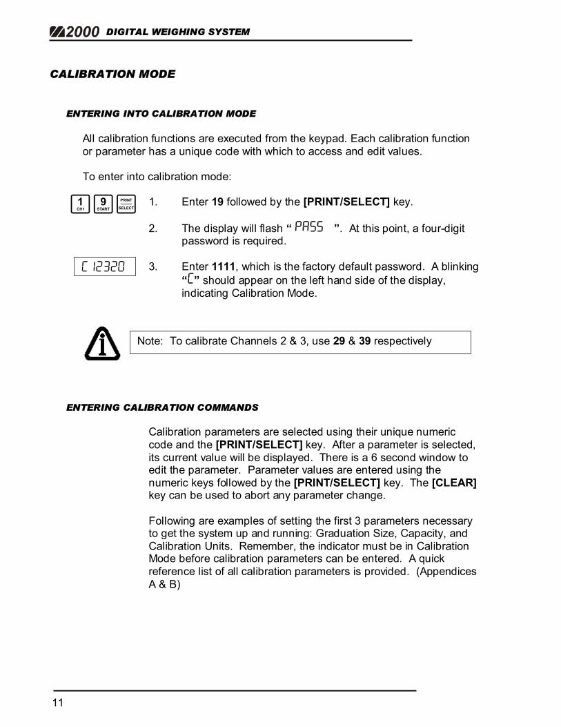
ENTERING INTO CALIBRATION MODE All calibration functions are executed from the keypad. Each calibration function or parameter has a unique code with which to access and edit values. To enter into calibration mode:
1. Enter 19 followed by the [PRINT/SELECT] key.
2. The display will flash “ PA55 ”. At this point, a four-digit password is required.
3. Enter 1111, which is the factory default password. A blinking
“C” should appear on the left hand side of the display, indicating Calibration Mode.
ENTERING CALIBRATION COMMANDS
Calibration parameters are selected using their unique numeric code and the [PRINT/SELECT] key. After a parameter is selected, its current value will be displayed. There is a 6 second window to edit the parameter. Parameter values are entered using the numeric keys followed by the [PRINT/SELECT] key. The [CLEAR] key can be used to abort any parameter change.
Following are examples of setting the first 3 parameters necessary to get the system up and running: Graduation Size, Capacity, and Calibration Units. Remember, the indicator must be in Calibration Mode before calibration parameters can be entered. A quick reference list of all calibration parameters is provided. (Appendices A & B)
Note: To calibrate Channels 2 & 3, use 29 & 39 respectively
12
SECTIONAL TRUCK SCALE INSTALLATION GUIDE
3P
4P
7P
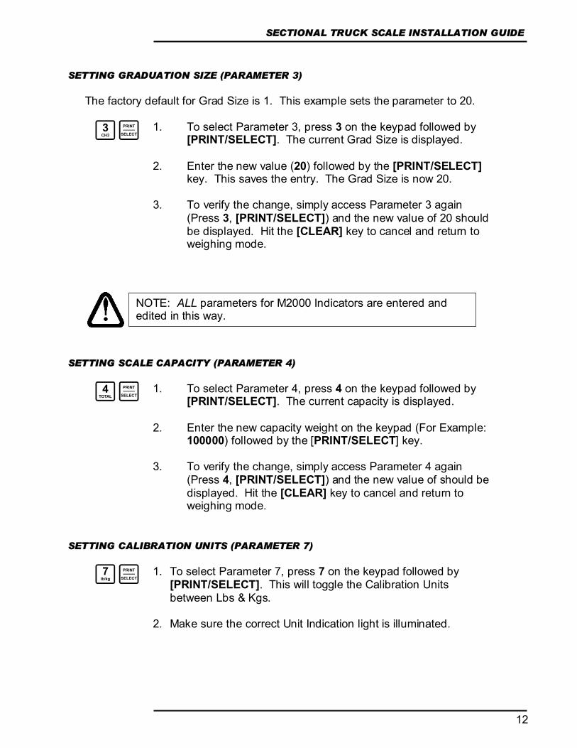
SETTING GRADUATION SIZE (PARAMETER 3)
The factory default for Grad Size is 1. This example sets the parameter to 20.
1. To select Parameter 3, press 3 on the keypad followed by [PRINT/SELECT]. The current Grad Size is displayed.
2. Enter the new value (20) followed by the [PRINT/SELECT]
key. This saves the entry. The Grad Size is now 20.
3. To verify the change, simply access Parameter 3 again (Press 3, [PRINT/SELECT]) and the new value of 20 should be displayed. Hit the [CLEAR] key to cancel and return to weighing mode.
SETTING SCALE CAPACITY (PARAMETER 4)
1. To select Parameter 4, press 4 on the keypad followed by
[PRINT/SELECT]. The current capacity is displayed.
2. Enter the new capacity weight on the keypad (For Example: 100000) followed by the [PRINT/SELECT] key.
3. To verify the change, simply access Parameter 4 again
(Press 4, [PRINT/SELECT]) and the new value of should be displayed. Hit the [CLEAR] key to cancel and return to weighing mode.
SETTING CALIBRATION UNITS (PARAMETER 7)
1. To select Parameter 7, press 7 on the keypad followed by [PRINT/SELECT]. This will toggle the Calibration Units between Lbs & Kgs.
2. Make sure the correct Unit Indication light is illuminated.
NOTE: ALL parameters for M2000 Indicators are entered and edited in this way.
DIGITAL WEIGHING SYSTEM
13
521P
4P C12320
12P
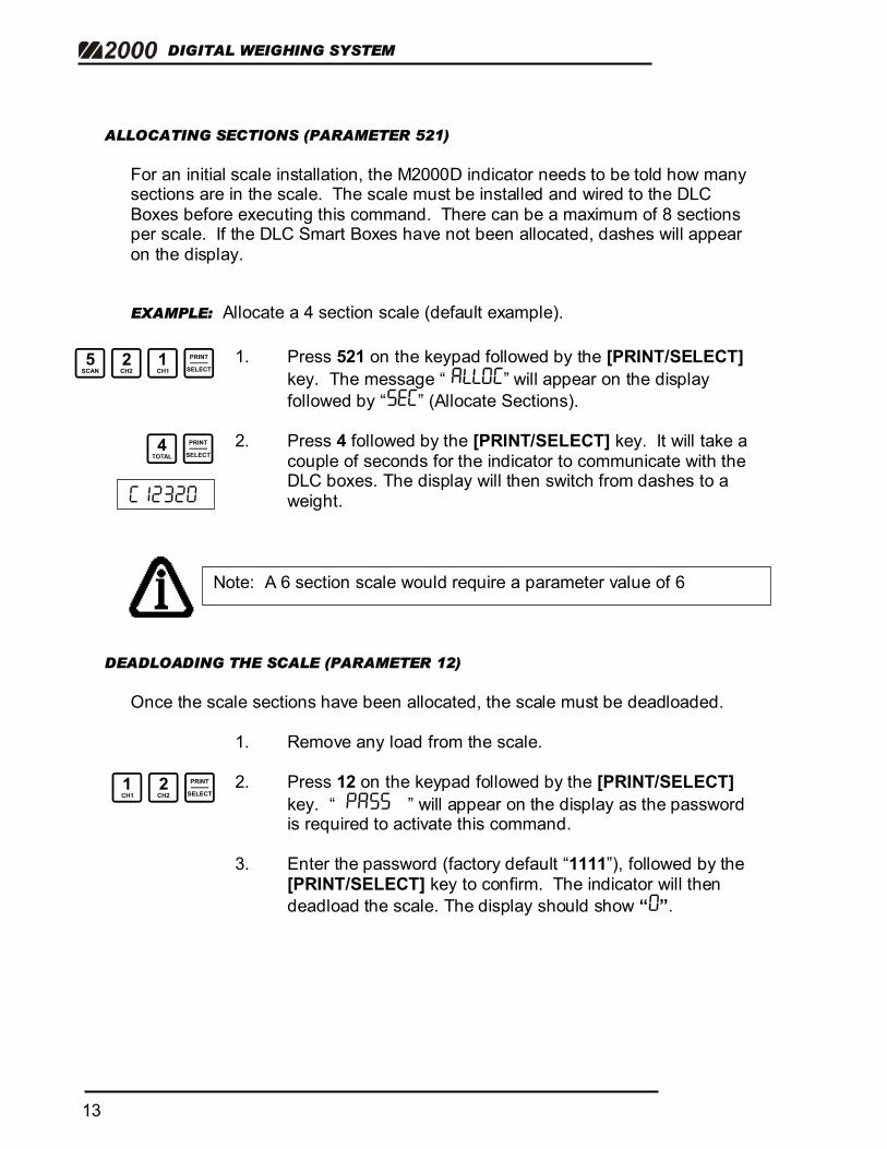
ALLOCATING SECTIONS (PARAMETER 521) For an initial scale installation, the M2000D indicator needs to be told how many sections are in the scale. The scale must be installed and wired to the DLC Boxes before executing this command. There can be a maximum of 8 sections per scale. If the DLC Smart Boxes have not been allocated, dashes will appear on the display.
EXAMPLE: Allocate a 4 section scale (default example).
1. Press 521 on the keypad followed by the [PRINT/SELECT] key. The message “ ALL0C” will appear on the display followed by “5EC” (Allocate Sections).
2. Press 4 followed by the [PRINT/SELECT] key. It will take a
couple of seconds for the indicator to communicate with the DLC boxes. The display will then switch from dashes to a weight.
DEADLOADING THE SCALE (PARAMETER 12)
Once the scale sections have been allocated, the scale must be deadloaded.
1. Remove any load from the scale. 2. Press 12 on the keypad followed by the [PRINT/SELECT]
key. “ PA55 ” will appear on the display as the password is required to activate this command.
3. Enter the password (factory default “1111”), followed by the
[PRINT/SELECT] key to confirm. The indicator will then deadload the scale. The display should show “0”.
Note: A 6 section scale would require a parameter value of 6

14
SECTIONAL TRUCK SCALE INSTALLATION GUIDE
13P
C10000
99P
10000
Pressing the [ON/OFF] key cycles the display between Graduated Counts (Displayed Weight prefixed by the blinking letter “C”) and Raw Counts (prefixed by the blinking letter “A”.)
SPANNING A SCALE WITH A TEST WEIGHT (PARAMETER 13)
1. Place your test weights on the scale. 2. Press 13 followed by the [PRINT/SELECT] key. 3. Enter the test weight value (Example: 10000) followed by the
[PRINT/SELECT] key. The indicator will calibrate the scale and the correct weight will be displayed.
HOW TO EXIT CALIBRATION MODE (PARAMETER 99)
• To exit Calibration Mode, enter 99 followed by the [PRINT/SELECT] key.
• The indicator display will show “Cal”, “5ave”, and “{}ait”.
• Weigh Mode will be entered with the scale weight being
displayed without the blinking “C” on the left hand side.
NOTE: None of the calibration changes are permanently saved until Calibration Mode is exited.

DIGITAL WEIGHING SYSTEM
15
ALL CHANNELS: This is the Electronic Address for the entire Scale. Values displayed include all Loadcells.
SECTION 1: Values displayed include Loadcells 1 & 2 combined.
SECTION 1, LOADCELL 1: Values displayed are for this Loadcell (corner) only.
SECTION 1, LOADCELL 2: Values displayed are for this Loadcell (corner) only.
Note: Press the [TARE] or [PRINT/SELECT] key to display the Electronic Address Screen.
NAVIGATING THE M2000
The “Status / Electronic Address” screen appears in Calibration Mode and is used to navigate through the various elements of the scale. Details of Scale Set-up and Status are also displayed. The most important LED digits for navigation are the 2nd digit (P or 5) and the last two digits ( “CH” on the diagram). These are the “Electronic Address”.
[S] = SECTIONAL Scale [H] = HOPPER Scale
[P] = PRIMARY DLC Smart Box [S] = SECONDARY DLC Smart Box (if necessary)
NUMBER OF SECTIONS allocated to the scale, in this case, 4. Each section contains 2 load cells (corners).
CHANNEL STATUS INFORMATION (USUALLY BLANK) [E] = Faulty corner/cell. Only the faulty corner/cell will have a flashing ‘E’ in
its status field. [D] = Corner/cell Disabled [A] = Corner / Section Adjustment mode activated. [_] = Cell allocated to another scale or not accessible to the user
(Fig. 9)
16
SECTIONAL TRUCK SCALE INSTALLATION GUIDE
P
P
T
T OR
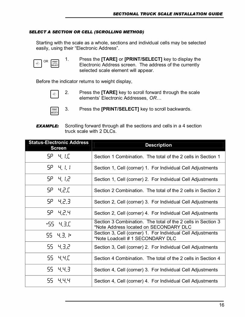
SELECT A SECTION OR CELL (SCROLLING METHOD)
Starting with the scale as a whole, sections and individual cells may be selected easily, using their “Electronic Address”.
1. Press the [TARE] or [PRINT/SELECT] key to display the Electronic Address screen. The address of the currently selected scale element will appear.
Before the indicator returns to weight display,
2. Press the [TARE] key to scroll forward through the scale elements’ Electronic Addresses, OR…
3. Press the [PRINT/SELECT] key to scroll backwards.
EXAMPLE: Scrolling forward through all the sections and cells in a 4 section
truck scale with 2 DLCs.
Status-Electronic Address Screen Description
5P 4.1.C Section 1 Combination. The total of the 2 cells in Section 1
5P 4.1.1 Section 1, Cell (corner) 1. For Individual Cell Adjustments
5P 4.1.2 Section 1, Cell (corner) 2. For Individual Cell Adjustments
5P 4.2.C Section 2 Combination. The total of the 2 cells in Section 2
5P 4.2.3 Section 2, Cell (corner) 3. For Individual Cell Adjustments
5P 4.2.4 Section 2, Cell (corner) 4. For Individual Cell Adjustments
*55 4.3.C Section 3 Combination. The total of the 2 cells in Section 3 *Note Address located on SECONDARY DLC
55 4.3.1* Section 3, Cell (corner) 1. For Individual Cell Adjustments *Note Loadcell # 1 SECONDARY DLC
55 4.3.2 Section 3, Cell (corner) 2. For Individual Cell Adjustments
55 4.4.C Section 4 Combination. The total of the 2 cells in Section 4
55 4.4.3 Section 4, Cell (corner) 3. For Individual Cell Adjustments
55 4.4.4 Section 4, Cell (corner) 4. For Individual Cell Adjustments

DIGITAL WEIGHING SYSTEM
17
3T
531P
P
5pa4.1.c
40
10
0
.
COARSE ADJUSTMENT
FINE ADJUSTMENT
QUICK SELECT METHOD (FOR SECTIONS) This method allows a technician to go directly to a particular section instead of scrolling through all the scale elements. To quickly jump to a section, enter the section number followed by the [TARE] key. EXAMPLE: Select Section 3.
1. Enter 3 followed by [TARE]. The display will briefly show the Electronic Address for confirmation and return back to weigh mode.
SECTIONAL ADJUSTMENT (PARAMETER 531) Before a sectional adjustment can be made, the specific section must be selected.
1. Enter 531 followed by the [PRINT/SELECT] key. The
display will flash the currently selected section.
2. Confirm the correct section by pressing the [PRINT/SELECT] key. The display will confirm by briefly showing the selected section with a flashing “A” to indicate that “ADJUST” mode has been entered. The display will return to weigh mode, showing the current weight on the scale.
3. TO INCREASE THE DISPLAYED WEIGHT: Pressing the
[IN] key will increment the number of counts, causing the displayed weight to increase. The keys 1,2,3 and 4 select the coarseness of the adjustment, where 4 is a very coarse and 1 is a very fine weight increment. When using fine weight increments, the [IN] key may need to be pressed several times to see the weight change.
TO DECREASE THE DISPLAYED WEIGHT: Pressing the [OUT] key will decrement the number of counts, reducing the displayed weight. The same Coarse and Fine adjustments apply.
Once the correction is complete, press the [TARE] button to exit Adjustment Mode.
5P 4.3.c

18
SECTIONAL TRUCK SCALE INSTALLATION GUIDE
2T 5p 4.2.c
5pa4.2.c
531P
P c 9920
5p 4.2.c
40 c 9960 0
c10020
1. C10020 .
c10000
T D0ne
EXAMPLE: Weight Correction on Section 2. Section 2 is weighing 9920 lbs. The actual weight on the scale is 10,000 lbs. 1. Use the Quick Select Method to select Section 2. Enter 2 followed by the
[TARE] key. The display will briefly confirm that you are pointing to Section 2.
2. Enter 531 followed by the [PRINT/SELECT] key. 3. Press [PRINT/SELECT] again to confirm Section 2. Note the flashing ‘A’
in the Channel Information digit. The weight (9920) will be displayed. The section can now be adjusted.
4. Press [IN] to increase the displayed weight. If nothing happens, select a
courser adjustment. (Step 5) 5. Press 4. Pressing the [IN] key will now cause a jump in the weight.
Continue to press 4 until the displayed weight approaches 10,000 lbs. If you overshoot the target weight, press [OUT] to reduce the weight.
6. At this point, fine-tuning may be required. 7. Press [TARE] to save adjustment values.
CORNER & SIDE-TO-SIDE ADJUSTMENTS (PARAMETER 531 CONTINUED)
Corner adjustments are identical to sectional adjustments. Instead of selecting a section to correct, select an individual loadcell.
NOTE: None of the calibration changes are permanently saved until Calibration Mode is exited.
DIGITAL WEIGHING SYSTEM
19
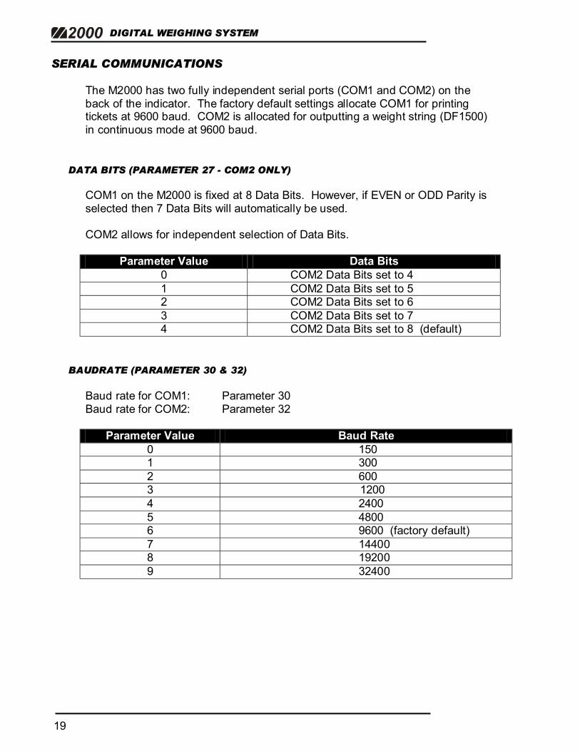
SERIAL COMMUNICATIONS The M2000 has two fully independent serial ports (COM1 and COM2) on the back of the indicator. The factory default settings allocate COM1 for printing tickets at 9600 baud. COM2 is allocated for outputting a weight string (DF1500) in continuous mode at 9600 baud.
DATA BITS (PARAMETER 27 - COM2 ONLY) COM1 on the M2000 is fixed at 8 Data Bits. However, if EVEN or ODD Parity is selected then 7 Data Bits will automatically be used. COM2 allows for independent selection of Data Bits.
Parameter Value Data Bits 0 COM2 Data Bits set to 4 1 COM2 Data Bits set to 5 2 COM2 Data Bits set to 6 3 COM2 Data Bits set to 7 4 COM2 Data Bits set to 8 (default)
BAUDRATE (PARAMETER 30 & 32) Baud rate for COM1: Parameter 30 Baud rate for COM2: Parameter 32
Parameter Value Baud Rate 0 150 1 300 2 600 3 1200 4 2400 5 4800 6 9600 (factory default) 7 14400 8 19200 9 32400

20
SECTIONAL TRUCK SCALE INSTALLATION GUIDE
PARITY (PARAMETER 31 & 33) Parity for COM1: Parameter 31 Parity for COM2: Parameter 33
Parameter Value Parity 0 No parity (factory default) 1 ODD parity 2 Even parity
STRING FORMATS FOR CONTINUOUS OUTPUT (PARAMETER 34 & 35) String Format for COM1: Parameter 34 String Format for COM2: Parameter 35 Several different indicator string formats are supported on the M2000. If creating a custom Output string for a ticket, the Com port connected to the printer must be set to 99. (See M2000 Ticket Formatting Guide)
Parameter Value Output String 1 DF1000 3 DF2000 5 DF2500 mode1 8 DF1500 (factory default) 9 DF2500 mode 6 10 DF2500 mode 7 12 AD4321, AD4323, AD5000 13 Cardinal 708 14 Cardinal 738 15 Toledo & Fairbanks R2500 16 Weightronix 120 17 Consolidated Controls UMC600 18 Analogic 5316 99 Set the com port to custom transmit mode
EXAMPLE: Output a UMC600 string from COM2.
1. Enter 35 on the keypad followed by the [PRINT/SELECT] key. 2. Press 17 followed by the [PRINT/SELECT] key.

DIGITAL WEIGHING SYSTEM
21
SERIAL HANDSHAKING - RTS/CTS (PARAMETER 36 & 37)
Handshaking for COM1: Parameter 36 Handshaking for COM2: Parameter 37
Parameter Value Hardware Handshaking 0 Disabled (default) 1 Enabled
COM PORT STRING OUTPUT MODE (PARAMETER 38 & 39) String Output Mode for COM1: Parameter 38 String Output Mode for COM2: Parameter 39 Both COM ports output continuously by default. Parameter Value String Transmits To COM Port…
1 When the PRINT/SELECT key has been pressed 2 When the COM port receive data input is at logic low (-9 volts dc) 3 When the COM port receive data input is at logic high (+9 volts dc) 4 When the ‘?’ character is received 5 Continuously (default)
CONFIGURING COM PORTS TO TRANSMIT IN RS422 MODE (PARAMETER 40) The wire connections to the COM ports on the back of the indicator are different for RS422 then for RS232. RS422 requires 2 lines for transmit (TX+ and TX-) and 2 lines for receive (RX+ and RX-).
FOR RS422 COMMUNICATIONS:
CTS on the connector becomes RX - RX on the connector becomes RX + TX on the connector becomes TX + RTS on the connector becomes TX -
Parameter Value COM1 COM2 0 (default) RS232 RS232
1 RS422 RS232 2 NOT CURRENTLY SUPPORTED 3 RS422 RS422

22
SECTIONAL TRUCK SCALE INSTALLATION GUIDE
TRANSMISSION DELAY FOR COM1 AND COM2 (PARAMETER 65) Some older equipment may experience problems keeping up to the high update rate of the M2000. Parameter 65 inserts delays between string transmissions to slow down the output rate. The delay can be set with ¼ second increments. Calibration mode must be exited before this parameter takes effect. The value entered for Calibration Parameter 65 must be a number between 0 – 100.
EXAMPLE: Update the strings on the serial ports once every second.
1. Enter 65 on the keypad followed by the [PRINT/SELECT] key.
2. Press 4, followed by the [PRINT/SELECT] key. For the fastest possible update, enter 0, which is the factory default.
DIGITAL WEIGHING SYSTEM
23
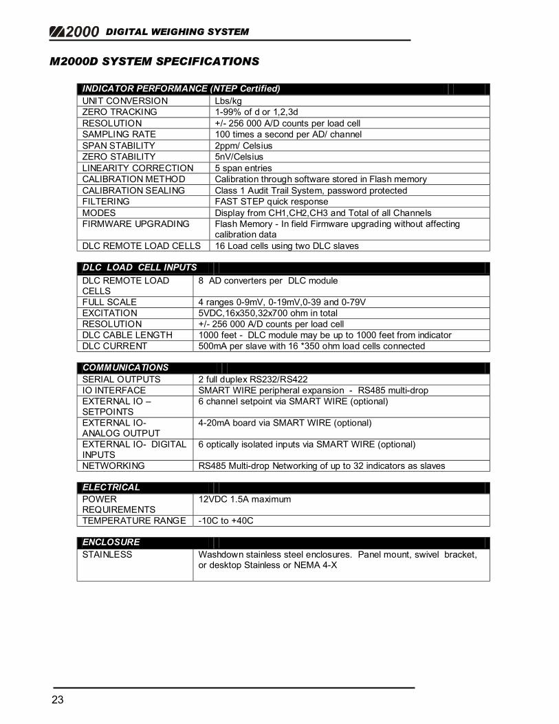
M2000D SYSTEM SPECIFICATIONS INDICATOR PERFORMANCE (NTEP Certified) UNIT CONVERSION Lbs/kg ZERO TRACKING 1-99% of d or 1,2,3d RESOLUTION +/- 256 000 A/D counts per load cell SAMPLING RATE 100 times a second per AD/ channel SPAN STABILITY 2ppm/ Celsius ZERO STABILITY 5nV/Celsius LINEARITY CORRECTION 5 span entries CALIBRATION METHOD Calibration through software stored in Flash memory CALIBRATION SEALING Class 1 Audit Trail System, password protected FILTERING FAST STEP quick response MODES Display from CH1,CH2,CH3 and Total of all Channels FIRMWARE UPGRADING Flash Memory - In field Firmware upgrading without affecting
calibration data DLC REMOTE LOAD CELLS 16 Load cells using two DLC slaves DLC LOAD CELL INPUTS DLC REMOTE LOAD CELLS
8 AD converters per DLC module
FULL SCALE 4 ranges 0-9mV, 0-19mV,0-39 and 0-79V EXCITATION 5VDC,16x350,32x700 ohm in total RESOLUTION +/- 256 000 A/D counts per load cell DLC CABLE LENGTH 1000 feet - DLC module may be up to 1000 feet from indicator DLC CURRENT 500mA per slave with 16 *350 ohm load cells connected COMMUNICATIONS SERIAL OUTPUTS 2 full duplex RS232/RS422 IO INTERFACE SMART WIRE peripheral expansion - RS485 multi-drop EXTERNAL IO – SETPOINTS
6 channel setpoint via SMART WIRE (optional)
EXTERNAL IO- ANALOG OUTPUT
4-20mA board via SMART WIRE (optional)
EXTERNAL IO- DIGITAL INPUTS
6 optically isolated inputs via SMART WIRE (optional)
NETWORKING RS485 Multi-drop Networking of up to 32 indicators as slaves ELECTRICAL POWER REQUIREMENTS
12VDC 1.5A maximum
TEMPERATURE RANGE -10C to +40C ENCLOSURE STAINLESS Washdown stainless steel enclosures. Panel mount, swivel bracket,
or desktop Stainless or NEMA 4-X
24
SECTIONAL TRUCK SCALE INSTALLATION GUIDE
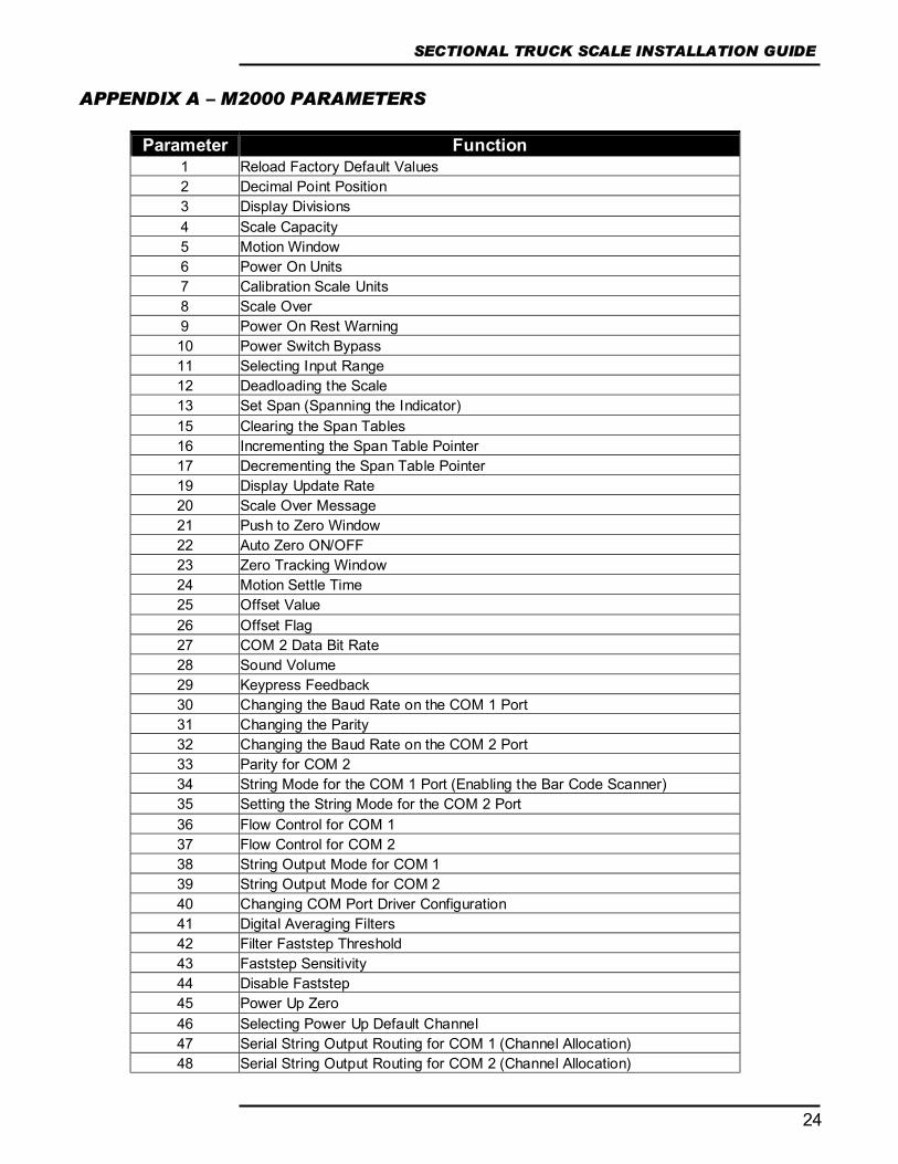
APPENDIX A – M2000 PARAMETERS
Parameter Function 1 Reload Factory Default Values 2 Decimal Point Position 3 Display Divisions 4 Scale Capacity 5 Motion Window 6 Power On Units 7 Calibration Scale Units 8 Scale Over 9 Power On Rest Warning 10 Power Switch Bypass 11 Selecting Input Range 12 Deadloading the Scale 13 Set Span (Spanning the Indicator) 15 Clearing the Span Tables 16 Incrementing the Span Table Pointer 17 Decrementing the Span Table Pointer 19 Display Update Rate 20 Scale Over Message 21 Push to Zero Window 22 Auto Zero ON/OFF 23 Zero Tracking Window 24 Motion Settle Time 25 Offset Value 26 Offset Flag 27 COM 2 Data Bit Rate 28 Sound Volume 29 Keypress Feedback 30 Changing the Baud Rate on the COM 1 Port 31 Changing the Parity 32 Changing the Baud Rate on the COM 2 Port 33 Parity for COM 2 34 String Mode for the COM 1 Port (Enabling the Bar Code Scanner) 35 Setting the String Mode for the COM 2 Port 36 Flow Control for COM 1 37 Flow Control for COM 2 38 String Output Mode for COM 1 39 String Output Mode for COM 2 40 Changing COM Port Driver Configuration 41 Digital Averaging Filters 42 Filter Faststep Threshold 43 Faststep Sensitivity 44 Disable Faststep 45 Power Up Zero 46 Selecting Power Up Default Channel 47 Serial String Output Routing for COM 1 (Channel Allocation) 48 Serial String Output Routing for COM 2 (Channel Allocation)
DIGITAL WEIGHING SYSTEM
25
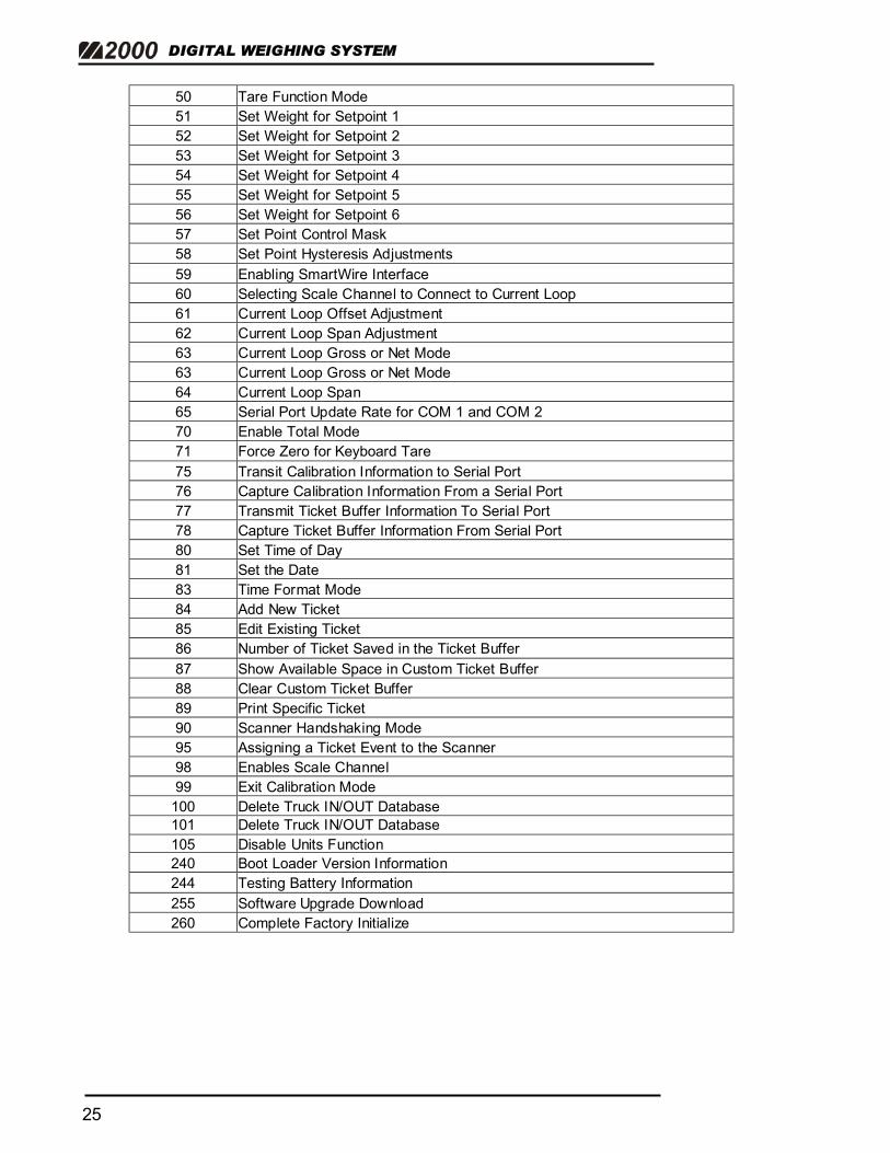
50 Tare Function Mode 51 Set Weight for Setpoint 1 52 Set Weight for Setpoint 2 53 Set Weight for Setpoint 3 54 Set Weight for Setpoint 4 55 Set Weight for Setpoint 5 56 Set Weight for Setpoint 6 57 Set Point Control Mask 58 Set Point Hysteresis Adjustments 59 Enabling SmartWire Interface 60 Selecting Scale Channel to Connect to Current Loop 61 Current Loop Offset Adjustment 62 Current Loop Span Adjustment 63 Current Loop Gross or Net Mode 63 Current Loop Gross or Net Mode 64 Current Loop Span 65 Serial Port Update Rate for COM 1 and COM 2 70 Enable Total Mode 71 Force Zero for Keyboard Tare 75 Transit Calibration Information to Serial Port 76 Capture Calibration Information From a Serial Port 77 Transmit Ticket Buffer Information To Serial Port 78 Capture Ticket Buffer Information From Serial Port 80 Set Time of Day 81 Set the Date 83 Time Format Mode 84 Add New Ticket 85 Edit Existing Ticket 86 Number of Ticket Saved in the Ticket Buffer 87 Show Available Space in Custom Ticket Buffer 88 Clear Custom Ticket Buffer 89 Print Specific Ticket 90 Scanner Handshaking Mode 95 Assigning a Ticket Event to the Scanner 98 Enables Scale Channel 99 Exit Calibration Mode
100 Delete Truck IN/OUT Database 101 Delete Truck IN/OUT Database 105 Disable Units Function 240 Boot Loader Version Information 244 Testing Battery Information 255 Software Upgrade Download 260 Complete Factory Initialize
26
SECTIONAL TRUCK SCALE INSTALLATION GUIDE
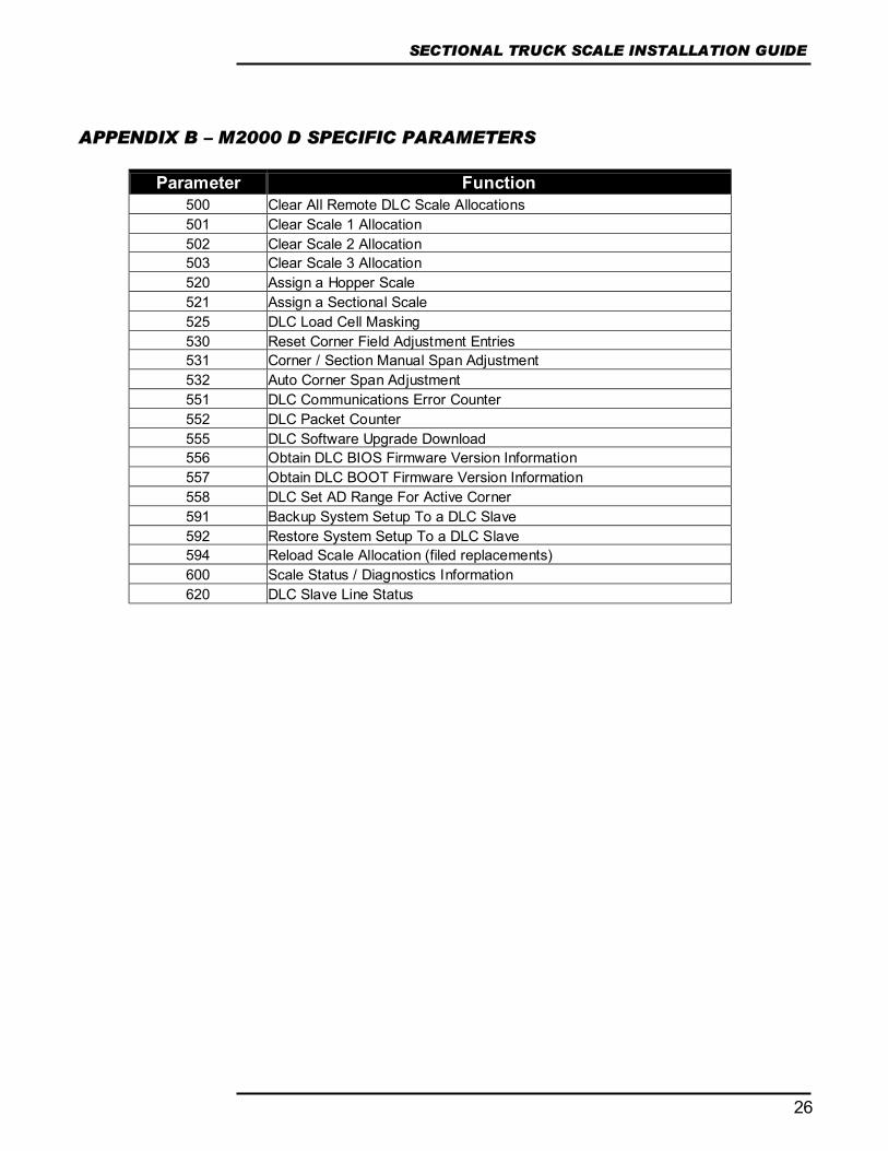
APPENDIX B – M2000 D SPECIFIC PARAMETERS
Parameter Function 500 Clear All Remote DLC Scale Allocations 501 Clear Scale 1 Allocation 502 Clear Scale 2 Allocation 503 Clear Scale 3 Allocation 520 Assign a Hopper Scale 521 Assign a Sectional Scale 525 DLC Load Cell Masking 530 Reset Corner Field Adjustment Entries 531 Corner / Section Manual Span Adjustment 532 Auto Corner Span Adjustment 551 DLC Communications Error Counter 552 DLC Packet Counter 555 DLC Software Upgrade Download 556 Obtain DLC BIOS Firmware Version Information 557 Obtain DLC BOOT Firmware Version Information 558 DLC Set AD Range For Active Corner 591 Backup System Setup To a DLC Slave 592 Restore System Setup To a DLC Slave 594 Reload Scale Allocation (filed replacements) 600 Scale Status / Diagnostics Information 620 DLC Slave Line Status

DIGITAL WEIGHING SYSTEM
27
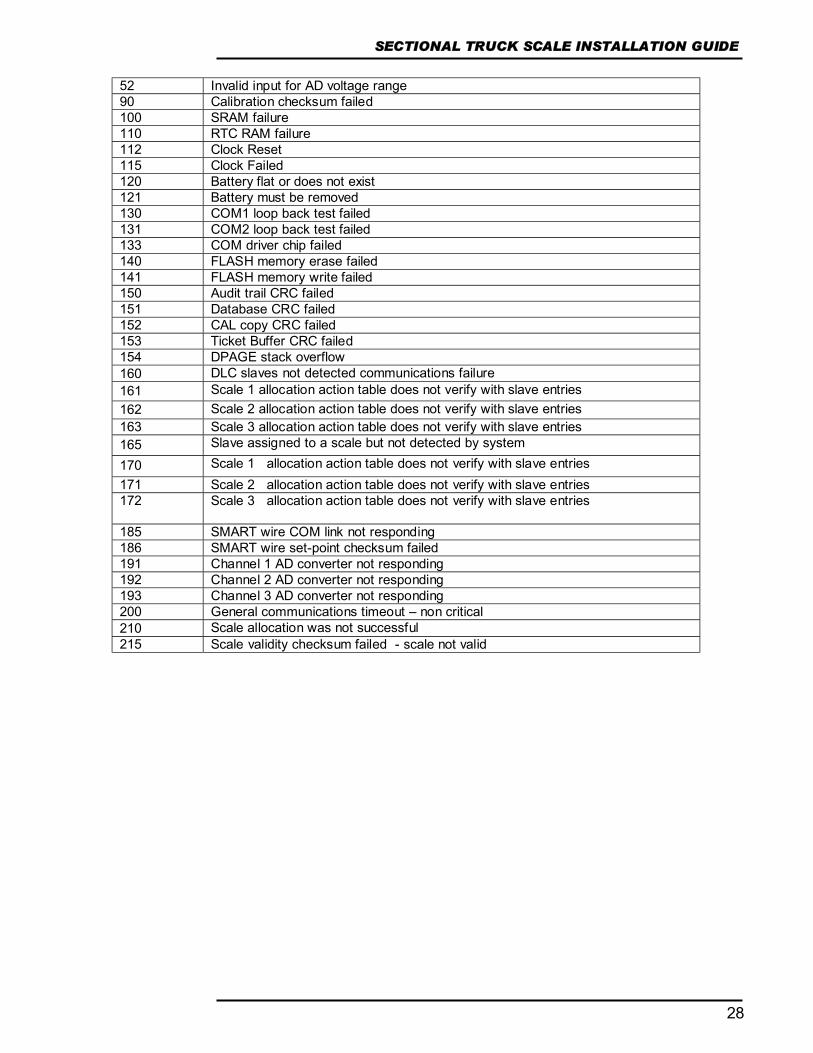
APPENDIX C - ERROR MESSAGES
1 Invalid parameter number for calibration mode 2 Graduation size invalid 3 Decimal Position Invalid 4 Flag values must be 1 for ‘ON’ and 0 for ‘OFF’ 5 Push to Zero Window must be 0-99 6 Zero tracking must be 1-99 or 100, 200, 300. 7 Only 1 will reset parameters 8 Only 1 will reset span table 9 Span exceeds maximum capacity or span too small 10 IZSM value can be 1 for ON and 0 for OFF 11 Test Weight units must be 0=lb or 1=kg. 12 Motion settle time out of range 1-100 13 Power on units may only be 0=lb, 1=kg. 14 Invalid Time entry HH.MM.SS 15 Invalid Date entry YY.MM.DD 16 Motion value is out of range 17 Press tare to increment span table, any other key invalid 18 Press tare to decrement span table, any other key invalid 19 Span table cannot be decremented past 1 20 Parameter memory write error, indicator requires service 21 Parameter checksum error, parameters have been lost. 22 Program check fault, indicator requires service 23 Invalid Serial Port speed setting 24 Invalid Serial Port Parity parameter 25 Cannot increment Span Table any further 26 Entered offset larger than Capacity 27 Invalid String mode for com port 28 Power on Zero warning 0=Off, 1=On 29 Channel enable is 0=Off and 1=On 30 Only 1 will set the deadload 31 Sound Volume can be between 0-3 32 Keypress feedback can be 0=OFF or 1=ON 33 Invalid Com String mode parameter 34 Invalid Com Port Interface value 35 * 36 * 37 Channel 1 cannot be disabled 38 Invalid Print Select Function Number 39 * 40 Scale channel is not enabled 41 Pushbutton Tare is invalid (Over, Motion, or disabled) 42 Keyboard tare available on channel 1 only 43 Tare greater than capacity 44 Invalid Password number range, can only be 0000-9999. 45 Only a value of 0, 1 or 80 is accepted as a parameter 46 * 47 Invalid Filter value 48 Invalid Filter Fast step value 49 Invalid Fast step Sensitivity 50 Invalid Fast step on/off 51 Invalid Tare Function Parameter 0-4
28
SECTIONAL TRUCK SCALE INSTALLATION GUIDE
52 Invalid input for AD voltage range 90 Calibration checksum failed 100 SRAM failure 110 RTC RAM failure 112 Clock Reset 115 Clock Failed 120 Battery flat or does not exist 121 Battery must be removed 130 COM1 loop back test failed 131 COM2 loop back test failed 133 COM driver chip failed 140 FLASH memory erase failed 141 FLASH memory write failed 150 Audit trail CRC failed 151 Database CRC failed 152 CAL copy CRC failed 153 Ticket Buffer CRC failed 154 DPAGE stack overflow 160 DLC slaves not detected communications failure 161 Scale 1 allocation action table does not verify with slave entries 162 Scale 2 allocation action table does not verify with slave entries 163 Scale 3 allocation action table does not verify with slave entries 165 Slave assigned to a scale but not detected by system 170 Scale 1 allocation action table does not verify with slave entries 171 Scale 2 allocation action table does not verify with slave entries 172
Scale 3 allocation action table does not verify with slave entries
185 SMART wire COM link not responding 186 SMART wire set-point checksum failed 191 Channel 1 AD converter not responding 192 Channel 2 AD converter not responding 193 Channel 3 AD converter not responding 200 General communications timeout – non critical 210 Scale allocation was not successful 215 Scale validity checksum failed - scale not valid