secundary operations guide - dsm | bright science ... · pdf filefor information on...
TRANSCRIPT

Secundary Operations guideMechanical Fasteners
Mechanical fasteners are generally used where connections can be easily assembled and disassembled.

2

3
Table of contents
1. BoltedAssembly 5
2. Molded-inThreads 9
3. CalculationofPlasticScrewThreads 15
4. ThreadedMetalInserts 17
5. BossCaps 21
6. Push-on/Turn-onfasteners 23
7. Self-TappingScrews 25
8. RivetedAssembly 31
9. Hook-and-LoopFasteners 33
10. Press-Fits 35
11. Snap-Fits 39
12 MaximumAllowableShort-TermStrain 49
13. CoefficientofFriction 51
14. Poisson’sRatio 53

4

5
1 Bolted Assembly

6
Bolted connections can be used when frequent assembly and disassembly of components are required, see figure 1.
Bolted connections are expensive and aesthetically are not the most elegant of connections due to the bolt head and nut being exposed. Since the bolts need tightening, which necessitates the use of tightening tools; the space available may be a constraint and has to be considered prior to designing.
Bolts and nuts are generally made of steel. The threads (both internal and external) can be molded in.
Bolts and nuts produced from thermoplastics are also available with standard machine threads. Thermoplastic bolts and nuts are ideally suited for applications where improved chemical resistance or electrical insulation is required. Thermoplastic bolts can solve the problem that may occur if steel bolts with a relatively low thermal expansion coefficient are used to join plastic components with a high thermal expansion coefficient.
To avoid overstressing during tightening, hollow bosses can be designed to accommodate the pre-stress, see figure 2. This also avoids the walls from buckling due to the high bending stresses.
Figure 1 Possibility for frequent (dis)assembly.
Figure 2 Hollow bosses are used to limit deflection.
7
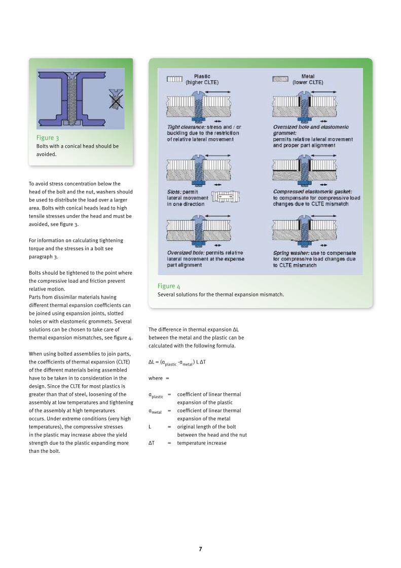
To avoid stress concentration below the head of the bolt and the nut, washers should be used to distribute the load over a larger area. Bolts with conical heads lead to high tensile stresses under the head and must be avoided, see figure 3.
For information on calculating tightening torque and the stresses in a bolt see paragraph 3.
Bolts should be tightened to the point where the compressive load and friction prevent relative motion. Parts from dissimilar materials having different thermal expansion coefficients can be joined using expansion joints, slotted holes or with elastomeric grommets. Several solutions can be chosen to take care of thermal expansion mismatches, see figure 4.
When using bolted assemblies to join parts, the coefficients of thermal expansion (CLTE) of the different materials being assembled have to be taken in to consideration in the design. Since the CLTE for most plastics is greater than that of steel, loosening of the assembly at low temperatures and tightening of the assembly at high temperatures occurs. Under extreme conditions (very high temperatures), the compressive stresses in the plastic may increase above the yield strength due to the plastic expanding more than the bolt.
The difference in thermal expansion ΔL between the metal and the plastic can be calculated with the following formula.
ΔL = (αplastic -αmetal ) L ΔT
where =
αplastic = coefficient of linear thermal expansion of the plastic
αmetal = coefficient of linear thermal expansion of the metal
L = original length of the bolt between the head and the nut
ΔT = temperature increase
Figure 3 Bolts with a conical head should be avoided.
Figure 4 Several solutions for the thermal expansion mismatch.

8
If the temperature increases, the thermal expansion of the two materials leads to the elongation of the bolt and the compression of the plastic. This will increase pre-stresses in the bolt and the plastic, as shown graphically in figure 5.
The force-displacement diagrams of the plastic construction and the bolt are shown
in the figures A and B respectively (see figure 5). The slope of the lines in these figures is determined by the stiffness of the bolt and the stiffness of the plastic construction. The two diagrams have been combined in figure C, whereby the distance between the origins of both curves is equal to ΔL. The resulting increase of the pre-stress can be determined.
The bolt head and the nut can be countersunk to improve appearance. Caps on the nuts are also a good way of improving aesthetics. Hexagonal shaped depressions can be molded into the parts to prevent the bold head or nut from rotating, simplifying the assembly operation and also making the aesthetics of the assembly better.
Figure 5 Increase of the pre-stress in the bolt.

9
2 Molded-in Threads

10
DesignMolded-in threads can be used when frequent assembly and disassembly are not required. Mechanical thread-forming operations are eliminated in that way. Both internal as well as external threads are commonly used.
When designing molded-in threads, the following rules must be taken into account.− Maximise the root radius to reduce stress concentrations, see figure 6.− Thread run-outs should preferably be rounded off to avoid cross threading and thread damage, see figure 7.− Avoid tapered (pipe) threads, unless a positive stop is provided, see figure 8. − Avoid very fine threads with a pitch smaller than 1 mm, considering mold filling and tolerances.− Special attention must be paid to construc- tions in which metal and plastic mate. Differences in thermal expansion and stiffness may lead to high stresses or loosening of a connection. Sharp edges on metal threads may damage the plastic.− The connection must be checked for high stresses due to tightening or loosening due to creep or stress relaxation.
Molding internal threadsInternal threads can be molded in several ways: − Stripped from the mold, − Collapsible cores, − Unscrewing devices, − Hand loaded threaded inserts.
Figure 6 Typical root radius: r = 0.14 P to 0.18 P.
Figure 7 Avoid sharp edges.
Figure 8 For tapered (pipe) threads, provide a positive stop.
11
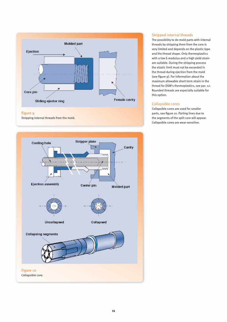
Stripped internal threadsThe possibility to de-mold parts with internal threads by stripping them from the core is very limited and depends on the plastic type and the thread shape. Only thermoplastics with a low E-modulus and a high yield strain are suitable. During the stripping process the elastic limit must not be exceeded in the thread during ejection from the mold (see figure 9). For information about the maximum allowable short-term strain in the thread for DSM’s thermoplastics, see par. 12. Rounded threads are especially suitable for this option.
Collapsible coresCollapsible cores are used for smaller parts, see figure 10. Parting lines due to the segments of the split core will appear. Collapsible cores are wear-sensitive.
Figure 9 Stripping internal threads from the mold.
Figure 10 Collapsible core.
12
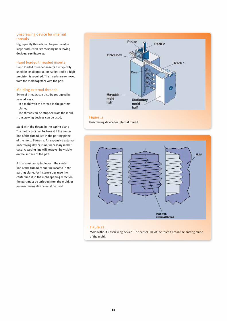
Unscrewing device for internal threadsHigh-quality threads can be produced in large production series using unscrewing devices, see figure 11.
Hand loaded threaded insertsHand loaded threaded inserts are typically used for small production series and if a high precision is required. The inserts are removed from the mold together with the part.
Molding external threadsExternal threads can also be produced in several ways: − In a mold with the thread in the parting plane,− The thread can be stripped from the mold,− Unscrewing devices can be used.
Mold with the thread in the paring planeThe mold costs can be lowest if the center line of the thread lies in the parting plane of the mold, figure 12. An expensive external unscrewing device is not necessary in that case. A parting line will however be visible on the surface of the part.
If this is not acceptable, or if the center line of the thread cannot be located in the parting plane, for instance because the center line is in the mold opening direction, the part must be stripped from the mold, or an unscrewing device must be used.
Figure 11 Unscrewing device for internal thread.
Figure 12 Mold without unscrewing device. The center line of the thread lies in the parting plane of the mold.
13
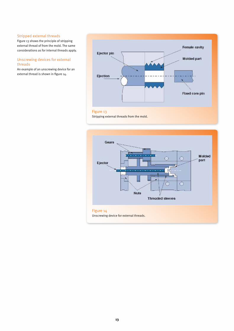
Stripped external threadsFigure 13 shows the principle of stripping external thread of from the mold. The same considerations as for internal threads apply.
Unscrewing devices for external threadsAn example of an unscrewing device for an external thread is shown in figure 14.
Figure 13 Stripping external threads from the mold.
Figure 14 Unscrewing device for external threads.

14

15
3 Calculation of Plastic Screw Threads
16
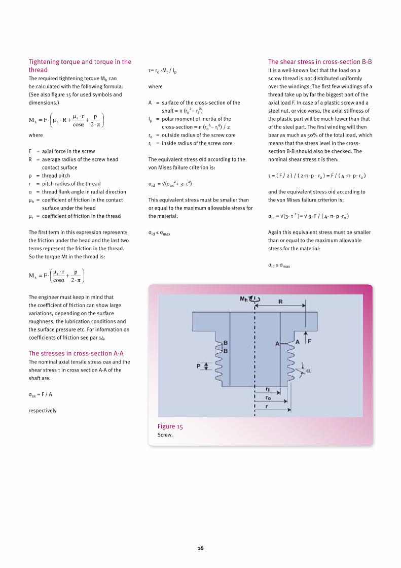
Tightening torque and torque in the threadThe required tightening torque Mh can be calculated with the following formula. (See also figure 15 for used symbols and dimensions.)
where
F = axial force in the screwR = average radius of the screw head contact surfacep = thread pitchr = pitch radius of the threadα = thread flank angle in radial directionµh = coefficient of friction in the contact surface under the head µt = coefficient of friction in the thread
The first term in this expression represents the friction under the head and the last two terms represent the friction in the thread. So the torque Mt in the thread is:
The engineer must keep in mind that the coefficient of friction can show large variations, depending on the surface roughness, the lubrication conditions and the surface pressure etc. For information on coefficients of friction see par 14.
The stresses in cross-section A-AThe nominal axial tensile stress σax and the shear stress τ in cross section A-A of the shaft are:
σax = F / A
respectively
τ= r0 ·Mt / lp
where
A = surface of the cross-section of the shaft = π (ro
2– ri2)
Ip = polar moment of inertia of the cross-section = π (ro
4– ri4) / 2
ro = outside radius of the screw coreri = inside radius of the screw core
The equivalent stress σid according to the von Mises failure criterion is:
σid = √(σax2+ 3· τ2)
This equivalent stress must be smaller than or equal to the maximum allowable stress for the material:
σid ≤ σmax
The shear stress in cross-section B-BIt is a well-known fact that the load on a screw thread is not distributed uniformly over the windings. The first few windings of a thread take up by far the biggest part of the axial load F. In case of a plastic screw and a steel nut, or vice versa, the axial stiffness of the plastic part will be much lower than that of the steel part. The first winding will then bear as much as 50% of the total load, which means that the stress level in the cross-section B-B should also be checked. The nominal shear stress τ is then:
τ = ( F / 2 ) / ( 2·π ·p · r0 ) = F / ( 4 ·π· p· r0 )
and the equivalent stress σid according to the von Mises failure criterion is:
σid = √(3· τ 2 )= √ 3· F / ( 4· π· p ·r0 )
Again this equivalent stress must be smaller than or equal to the maximum allowable stress for the material:
σid ≤ σmax
Figure 15 Screw.
11
⋅
+⋅
+⋅⋅=
2
p
cosr
RFM t
hh
⋅
+⋅
⋅=
2
p
cosr
FM t
h
11
⋅
+⋅
+⋅⋅=
2
p
cosr
RFM t
hh
⋅
+⋅
⋅=
2
p
cosr
FM t
h

17
4 Threaded Metal Inserts

18
Insertion is a way to create a connection that can be assembled and disassembled repeatedly without problems. A metal part is inserted in the thermoplastic and the connection can be made using a standard screw or bolt.
Bosses are required in most cases. They should be properly designed to avoid sink-marks, internal stresses and warpage. Sink-marks will be less visible on dull surfaces, light colors, machined surfaces and round edges.
The different insertion techniques that are used will be discussed in more detail.
Ultrasonic insertionThe insert is pressed into a hole in the plastic by a horn that vibrates at ultrasonic frequency. The ultrasonic energy melts the plastic around the insert. Once the insert is pressed in, the plastic freezes off evenly around the insert.
Inserts as shown in figure 16 specially developed for ultrasonic insertion, are commercially available in various types and sizes.
Ultrasonic insertion gives a shorter molding cycle than parts with molded-in inserts. However, it also represents an additional manufacturing process. Care should always be taken to ensure the insert is solidly embedded in the substrate.
Heated insertsA special press that pre-heats the insert is used for hot pressing-in. The inserts are pressed into the hole when they have reached the desired temperature. The heat-transfer melts the polymer and the molten polymer flows into the undercuts and secures the insert after cooling down.
The advantages are: − strong connection, high loads can be absorbed− low internal stresses in the plastic if well- designed and executed− low equipment costs compared to ultrasonic insertion.
A longer insertion time is needed however, for heating-up and cooling-down the plastic.
Cold pressed-in insertsInserts can also be pressed directly into a hole. This can be done cold as well as hot. Pressing-in cold is done with a small press. The inserts are provided with knurls under an angle at the outside. It is the fastest and easiest way of insertion, but high stresses will be present in the material round the insert making the connection weak.
Figure 17 Pressed-in inserts.
Figure 16 Insert for ultrasonic insertion.
19
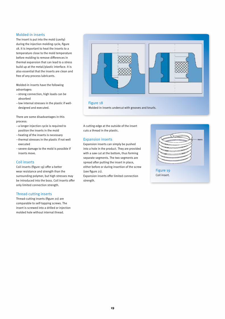
Molded-in insertsThe insert is put into the mold (cavity) during the injection molding cycle, figure 18. It is important to heat the inserts to a temperature close to the mold temperature before molding to remove differences in thermal expansion that can lead to a stress build up at the metal/plastic interface. It is also essential that the inserts are clean and free of any process lubricants.
Molded-in inserts have the following advantages: − strong connection, high loads can be absorbed− low internal stresses in the plastic if well- designed and executed.
There are some disadvantages in this process: − a longer injection cycle is required to position the inserts in the mold − heating of the inserts is necessary − thermal stresses in the plastic if not well executed − severe damage to the mold is possible if inserts move.
Coil insertsCoil inserts (figure 19) offer a better wear resistance and strength than the surrounding polymer, but high stresses may be introduced into the boss. Coil inserts offer only limited connection strength.
Thread-cutting insertsThread-cutting inserts (figure 20) are comparable to self-tapping screws. The insert is screwed into a drilled or injection molded hole without internal thread.
A cutting edge at the outside of the insert cuts a thread in the plastic.
Expansion insertsExpansion inserts can simply be pushed into a hole in the product. They are provided with a saw cut at the bottom, thus forming separate segments. The two segments are spread after putting the insert in place, either before or during insertion of the screw (see figure 21).Expansion inserts offer limited connection strength.
Figure 18 Molded-in inserts undercut with grooves and knurls.
Figure 19 Coil insert.

20
Recommendations:− design simple inserts with undercuts for pull-out retention and grooves or knurls for torque retention − avoid sharp corners− use brass, stainless steel or plated steel inserts; raw steel inserts may rust− use clean inserts to safeguard optimal interfacing between the metal and the thermoplastic (free from oil, grease, etc.)
− ensure that adjacent walls have sufficient thickness to prevent the insert from being pulled out during assembly− keep knurls away from part edges for notch sensitivity.
Figure 21 Expansion insert.
Figure 20 Thread-cutting inserts.

21
5 Boss Caps
22
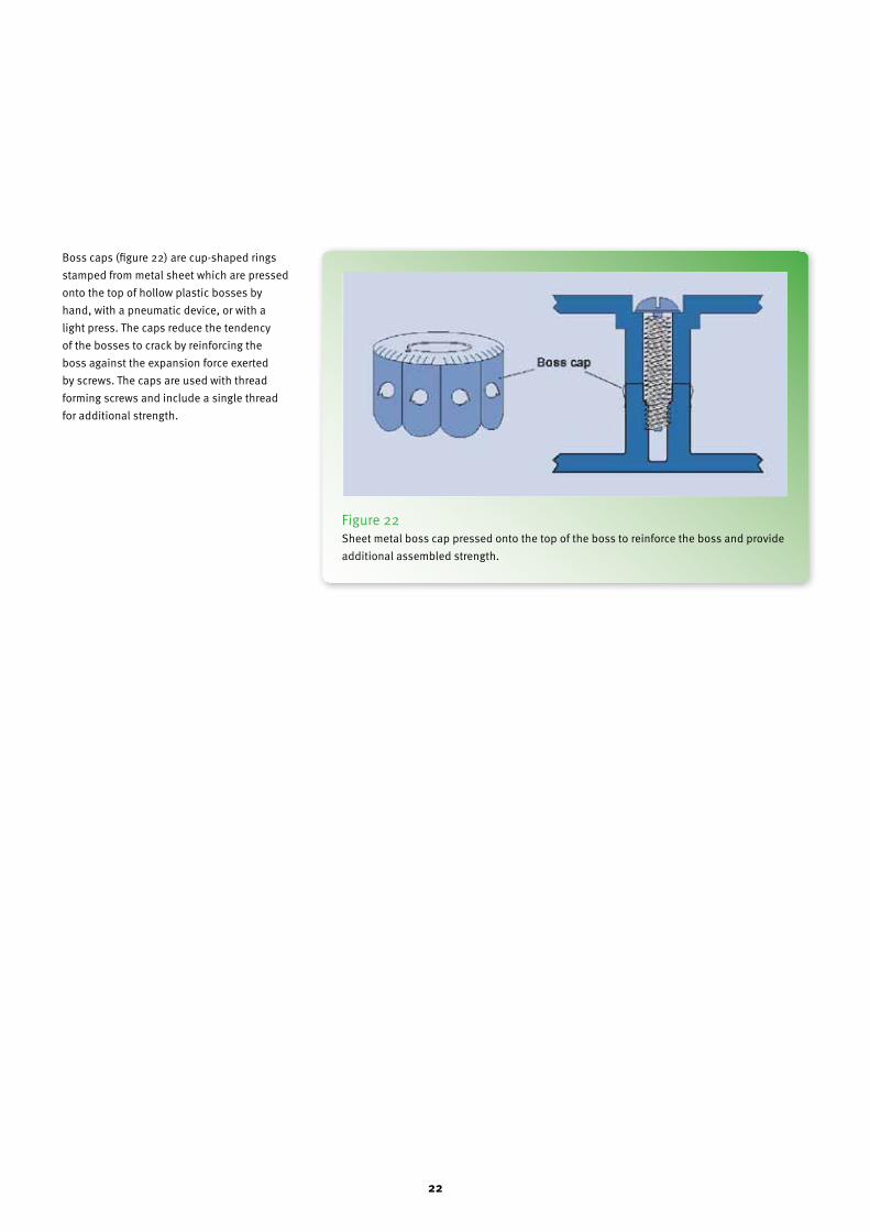
Boss caps (figure 22) are cup-shaped rings stamped from metal sheet which are pressed onto the top of hollow plastic bosses by hand, with a pneumatic device, or with a light press. The caps reduce the tendency of the bosses to crack by reinforcing the boss against the expansion force exerted by screws. The caps are used with thread forming screws and include a single thread for additional strength.
Figure 22 Sheet metal boss cap pressed onto the top of the boss to reinforce the boss and provide additional assembled strength.

23
6 Push-on/Turn-on fasteners
24
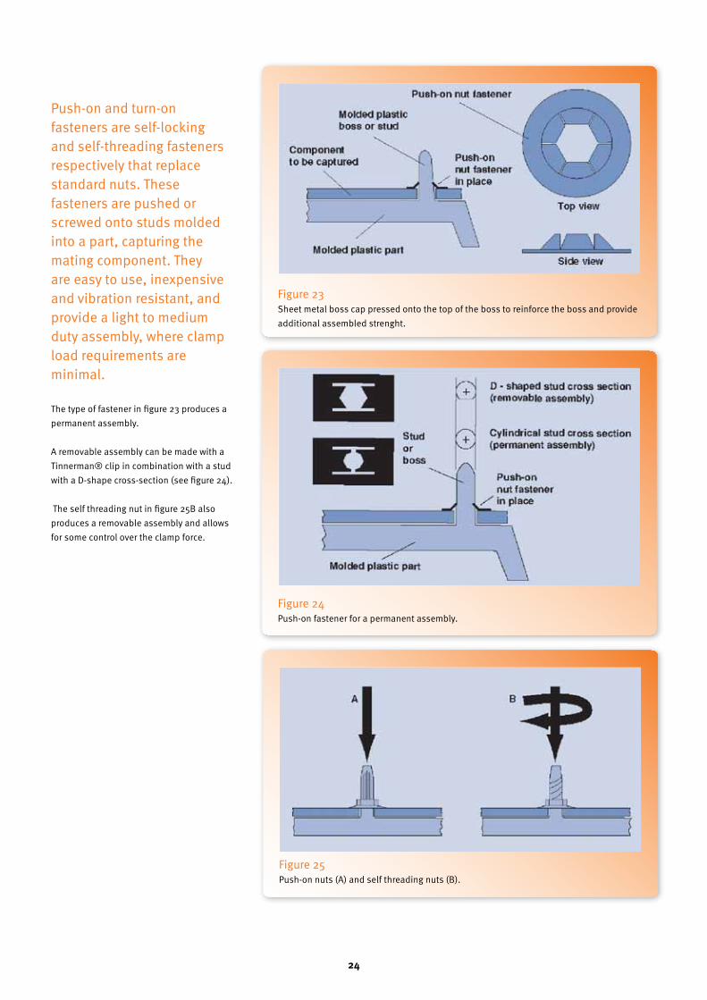
Push-on and turn-on fasteners are self-locking and self-threading fasteners respectively that replace standard nuts. These fasteners are pushed or screwed onto studs molded into a part, capturing the mating component. They are easy to use, inexpensive and vibration resistant, and provide a light to medium duty assembly, where clamp load requirements are minimal.
The type of fastener in figure 23 produces a permanent assembly.
A removable assembly can be made with a Tinnerman® clip in combination with a stud with a D-shape cross-section (see figure 24).
The self threading nut in figure 25B also produces a removable assembly and allows for some control over the clamp force.
Figure 23 Sheet metal boss cap pressed onto the top of the boss to reinforce the boss and provide additional assembled strenght.
Figure 24 Push-on fastener for a permanent assembly.
Figure 25 Push-on nuts (A) and self threading nuts (B).

25
7 Self-Tapping Screws
26
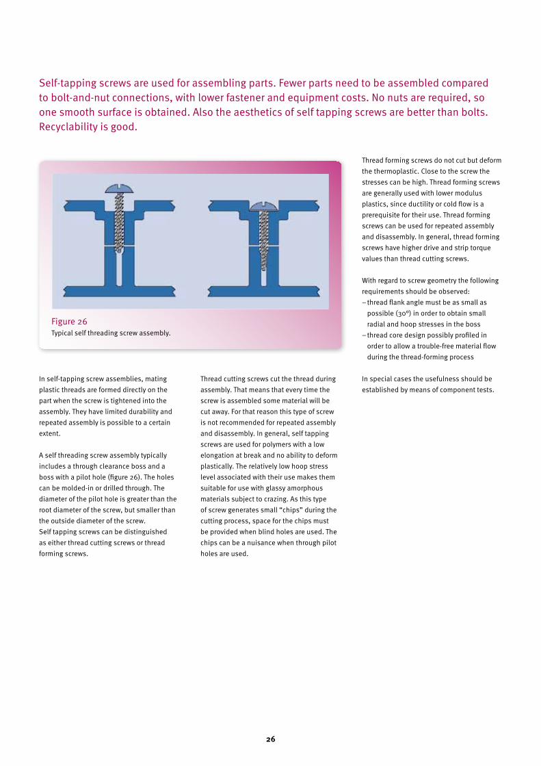
In self-tapping screw assemblies, mating plastic threads are formed directly on the part when the screw is tightened into the assembly. They have limited durability and repeated assembly is possible to a certain extent.
A self threading screw assembly typically includes a through clearance boss and a boss with a pilot hole (figure 26). The holes can be molded-in or drilled through. The diameter of the pilot hole is greater than the root diameter of the screw, but smaller than the outside diameter of the screw.Self tapping screws can be distinguished as either thread cutting screws or thread forming screws.
Thread cutting screws cut the thread during assembly. That means that every time the screw is assembled some material will be cut away. For that reason this type of screw is not recommended for repeated assembly and disassembly. In general, self tapping screws are used for polymers with a low elongation at break and no ability to deform plastically. The relatively low hoop stress level associated with their use makes them suitable for use with glassy amorphous materials subject to crazing. As this type of screw generates small “chips” during the cutting process, space for the chips must be provided when blind holes are used. The chips can be a nuisance when through pilot holes are used.
Thread forming screws do not cut but deform the thermoplastic. Close to the screw the stresses can be high. Thread forming screws are generally used with lower modulus plastics, since ductility or cold flow is a prerequisite for their use. Thread forming screws can be used for repeated assembly and disassembly. In general, thread forming screws have higher drive and strip torque values than thread cutting screws.
With regard to screw geometry the following requirements should be observed:− thread flank angle must be as small as possible (30°) in order to obtain small radial and hoop stresses in the boss− thread core design possibly profiled in order to allow a trouble-free material flow during the thread-forming process
In special cases the usefulness should be established by means of component tests.
Self-tapping screws are used for assembling parts. Fewer parts need to be assembled compared to bolt-and-nut connections, with lower fastener and equipment costs. No nuts are required, so one smooth surface is obtained. Also the aesthetics of self tapping screws are better than bolts. Recyclability is good.
Figure 26 Typical self threading screw assembly.

27
Standard thread cutting screwsFigure 27 shows some examples of standard thread cutting screws. These screws are provided with cutting slots.
The type BT (formerly known as type 25) screw is the most common standard thread cutting screw due to its wide thread spacing and generous cutting slot. The type BF screw also has wide thread spacing, but the slotted cutting flights may tend to clog when work-ing with softer materials. The B series screws have been used with materials having a flexural modulus as a low as 1400 MPa.
The type T (or 23) is often useful with very high modulus glass reinforced materials with a flexural modulus greater than 7000 MPa.
Standard thread forming screwsThread forming screws do not contain cutting slots and do not produce chips. They are generally used with plastics with a modulus smaller than 3000 MPa. Figure 28 shows some examples.
These standard screws with their 60° thread angle generate relatively high radial and hoop stresses. The wider thread spacing of the types AB and B is recommended over the type C for most applications. The gimlet point of the type AB necessitates extra long bosses as the tapered point does not contribute to the strength of the connection.
Figure 27 Standard thread cutting screws.
Figure 28 Standard thread forming screws.

28
Self-tapping screws designed for plasticsHiLo® screws are designed with a double lead, consisting of a high and a low thread. The screw thread configuration has a smaller minor diameter than that of conventional screws and the high threads make a deeper cut into the material between the threads, contributing to greater resistance to pullout and stronger fastening. The high thread has a 30° thread angle and the low thread has a 60° thread angle.
The screws are available in thread cutting and thread forming varieties and with different point and head styles.
Plastite® thread-forming screws have a more or less triangular cross-section, which reduces the driving torque. After installation, cold flow of the plastic effectively locks the screw in place, increasing the resistance to loosening and making the screw ideal for vibration applications (see figure 30).
PT® screws, supplied by Ejot, are thread-forming screws with a 30° thread angle and a modified shank, which is said to improve plastic flow during the thread forming operation (see figure 31).
Polyfast® screws have an asymmetric screw profile. The widely spaced flights have a 35 leading edge and a 10° trailing edge (see figure 32).
Figure 29 HiLo® screws
Figure 31 PT® screws for plastics up to 40% GF.
Figure 32 Polyfast® screws.
Figure 33
Figure 30 Plastite® thread-forming screws
29
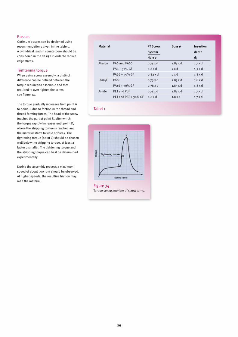
BossesOptimum bosses can be designed using recommendations given in the table 1.A cylindrical lead-in counterbore should be considered in the design in order to reduce edge stress.
Tightening torqueWhen using screw assembly, a distinct difference can be noticed between the torque required to assemble and that required to over tighten the screw, see figure 34.
The torque gradually increases from point A to point B, due to friction in the thread and thread forming forces. The head of the screw touches the part at point B, after which the torque rapidly increases until point D, where the stripping torque is reached and the material starts to yield or break. The tightening torque (point C) should be chosen well below the stripping torque, at least a factor 2 smaller. The tightening torque and the stripping torque can best be determined experimentally.
During the assembly process a maximum speed of about 500 rpm should be observed. At higher speeds, the resulting friction may melt the material.
Tabel 1
Figure 34 Torque versus number of screw turns.
Material PTScrew Bossø Insertion
System depth
Holeø diAkulon PA6 and PA66 0.75 x d 1.85 x d 1.7 x d
PA6 + 30% GF 0.8 x d 2 x d 1.9 x d
PA66 + 30% GF 0.82 x d 2 x d 1.8 x d
Stanyl PA46 0.73 x d 1.85 x d 1.8 x d
PA46 + 30% GF 0.78 x d 1.85 x d 1.8 x d
Arnite PET and PBT 0.75 x d 1.85 x d 1.7 x d
PET and PBT + 30% GF 0.8 x d 1.8 x d 1.7 x d

30

31
8 Riveted Assembly

32
Rivets provide a simple and economic assembly pro-cess, and produce a strong permanent mechanical joint. They are used to join thin sections of plastics, plastic to metal sheet or plastics to fabric. The process can easily be automated. Different types of rivet heads are available, as shown in figure 35.
The diameter of the head must preferably be three times the shank diameter to reduce the stresses in the parts by distributing the clamp force over a larger area. A conical head should not be used, as it produces high tensile stresses.
Rivets can be produced from metal or plastic. Aluminium and plastic rivets produce smaller compressive stresses in the parts.
A 0.25mm (0.010 inch) clearance between the rivet and the molded hole is recommended to account for tolerance variations and the coefficient of thermal expansion mismatch. A head is formed at the shank by plastic deformation of the material. The head can be made with a hand vice or a press.
Figure 36 shows a typical example of a heading tool. Load control devices should preferably be used during rivet installation to ensure correct clinching pressure and consistent assembly thickness.
A reinforcing washer under the head of the rivet helps to minimise the stresses in the parts, just like a shouldered rivet (see figure 37 and 38).
Figure 35 Different types of rivets.
Figure 36 Heading tool.
Figure 37 Reinforcing under the head of the rivet.
Figure 38 Formed head on a rivet.

33
9 Hook-and-Loop Fasteners
34
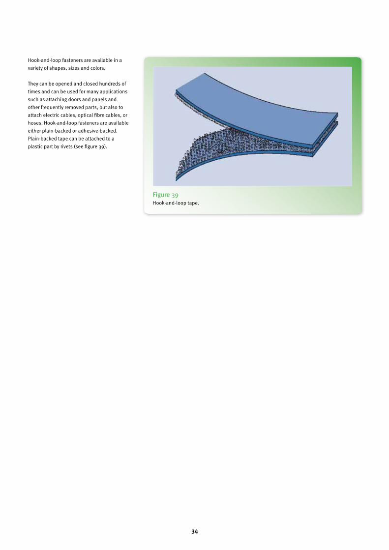
Hook-and-loop fasteners are available in a variety of shapes, sizes and colors.
They can be opened and closed hundreds of times and can be used for many applications such as attaching doors and panels and other frequently removed parts, but also to attach electric cables, optical fibre cables, or hoses. Hook-and-loop fasteners are available either plain-backed or adhesive-backed. Plain-backed tape can be attached to a plastic part by rivets (see figure 39).
Figure 39 Hook-and-loop tape.

35
10 Press-Fits

36
IntroductionPress-fits are a simple and cost effective means to connect two parts. A press-fit is usually applied to connect a hub to a solid or hollow shaft, or to fix a bush in a housing. Interference between the two parts supplies the required pre-stress to enable the connection to transmit an axial force or a torque.
The hub and the shaft may both be of plastic, but a combination of plastic and metal is also possible. If different materials are used, attention must be paid to differences in thermal expansion, which may cause loosening of the connection or too high stresses.
Stress relaxationStress relaxation in the plastic may also lead to loos-ening of the connection. Isochronous stress-strain curves can supply information about the stress relaxation that will take place, see figure 40.
The stress level immediately after assem-bling is σ0 in this example, at a strain level ε0. After a certain time the stress reduces to σ(t), while the strain remains constant. This means that the relaxation modulus
Er = σ(t) / ε0
should be used in the calculations to determine if the connection will still fun c-tion during the design life time t.
Coefficient of frictionThe external force or torque that can be transmitted by the connection depends on the coeffi-cient of friction μ.
For information about this coefficient see par 13.
Poisson’s ratioPoisson’s ratio must be known to calculate the surface pressure between the shaft and the hub, and the material stresses in the shaft and the hub.For information about this ratio see par 14.
Surface pressure between the hub and the shaftThe theory for thick-walled cylinders is outlined below, neglecting edge effects.
General caseThe surface pressure p between the hub and the shaft is:
where A and B are geometry factors with
di = inside diameter of the shaftdo = outside diameter of the shaftDi = inside diameter of the hubDo = outside diameter of the hubEh = modulus of the hub materialEs = modulus of the shaft materiali = interference between hub and shaft =do– Divh = Poisson’s ratio of the hub materialvs = Poisson’s ratio of the shaft material
Figure 40 Creep and stress relaxation.
37
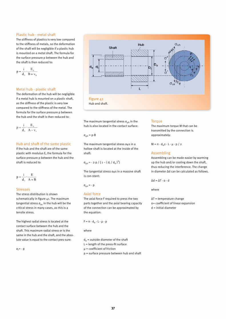
Plastic hub - metal shaftThe stiffness of plastics is very low compared to the stiffness of metals, so the deformation of the shaft will be negligible if a plastic hub is mounted on a metal shaft. The formula for the surface pressure p between the hub and the shaft is then reduced to:
Metal hub - plastic shaftThe deformation of the hub will be negligible if a metal hub is mounted on a plastic shaft, as the stiffness of the plastic is very low compared to the stiffness of the metal. The formula for the surface pressure p between the hub and the shaft is then reduced to:
Hub and shaft of the same plasticIf the hub and the shaft are of the same plastic with modulus E, the formula for the surface pressure p between the hub and the shaft is reduced to:
StressesThe stress distribution is shown schematically in figure 41. The maximum tangential stress σwh in the hub will be the critical stress in many cases, as this is a tensile stress.
The highest radial stress is located at the contact surface between the hub and the shaft. This maximum radial stress σr is the same in the hub and the shaft, and the abso-lute value is equal to the contact pres-sure:
σr= - p
The maximum tangential stress σwh in the hub is also located in the contact surface:
σwh = p·B
The maximum tangential stress σws in a hollow shaft is located at the inside of the shaft:
σws = - 2·p / { 1 – ( di / do )2}
The tangential stress σws in a massive shaft is con-stant:
σws = - p
Axial forceThe axial force F required to press the two parts together and the axial bearing capacity of the connection can be approximated by the equation:
F = π · do · L · μ · p
where
do = outside diameter of the shaftL = length of the press-fit surfaceμ = coefficient of frictionp = surface pressure between hub and shaft
TorqueThe maximum torque M that can be transmitted by the connection is approximately:
M = π · do2 · L · μ · p / 2
AssemblingAssembling can be made easier by warming up the hub and/or cooling down the shaft, thus reducing the interference. The change in diameter Δd can be calculated as follows.
Δd = ΔT · α · d
where
ΔT = temperature changeα= coefficient of linear expansiond = initial diameter
Figure 41 Hub and shaft.

38

39
11 Snap-Fits

40
IntroductionA snap-fit is an effective method to design the fasten-ing system into the product design itself. A snap-fit can be designed to allow parts to be either permanently fastened (or pre-determined to be broken off) or for frequent assembly and disassembly.
In combination with O-rings or proper seals, even gas and fluid tight connections can be made.
Designing a snap-fit is rather complex due to a combination of factors:− the functional requirements of the product− the assembly requirements− the mechanical properties of the thermoplastic− the design of the mold and notably part ejection.
Snap-fits can be found in a wide variety of shapes. Three examples are shown here (Figures 42, 43, 44).
Figure 42 Snap-fit cantilever beam tip.
Figure 43 Snap-fit cylindrical type.

41
The force-deflection diagramIn the general case, both parts will be defor-med during assembling, see the example in figure 45. Part 1 is bent down wards over a distance y1, part 2 is bent upwards over a distance y2 and a deflection force Fb acts between the two mating parts.
A force-deflection diagram as shown in figure 46 can be a useful aid for the engineer to determine how the total deflection will be distributed over the two parts.
The undercut h of the snap-fit determines the total deformation y1 + y2 in this diagram and the spring characteristic (stiffness) of both parts determines the deflection force Fb.
Secant modulusThe spring characteristic of the parts must be calculated from the part dimensions and the material stiffness E. Young’s modulus E0 may be used as long as the strains remain in the proportionality range of the stress-strain curve, but for larger strains the secant modulus Es should be used. Figure 47 shows the definition of Es.
The strain will vary from place to place, so that the calculation should in fact be done using several secant moduli. This is not feasible for a hand calculation, in that case the engineer will normally use an average secant modulus. One of the advantages of a finite element calculation is that the complete stress-strain curve of a material can be used as input, with the computer determining the strain and modulus for every point of the construction.
Maximum allowable short-term strain during assemblingIf a snap-fit fails during assembly, the maximum deflection of the cantilever beam most likely exceed-ed the deflection limit of the thermoplastic used. The maximum strain that occurs during assembling can be calculated for both parts if the force-deflection diagram of figure 46 is known.
For information about the maximum allowable short-term strain level ε in DSM thermoplastics see par. 12.
Since the snap-fit is only a small part of a product, it is better to design snap-fit dimensions based on the selected thermoplastic rather than to choose a thermoplastic to make a specific snap-fit work.
Figure 44 Snap-fit spherical type
Figure 45 Both parts are deformed.

42
Creep and stress relaxationInternal loads in the snap-fit connection after assembly should be avoided if possible, due to possible creep and stress relaxation. A graph with isochronous stress-strain curves gives information about the creep and stress relaxation that will take place, see figure 40.
If a certain pre-stress cannot be avoided, as the connection has to resist an external load, this pre-stress should be minimized. The designer should be aware that both the possibility of breakage and the required force to (dis)assemble can be dealt with indepen-dently. In most cases the number of snap-fits can be changed.
Stress concentrationsA common factor causing failure of a snap-fit is the inside radius r (see figure 45) in transitions or the lack thereof. An inside radius which is too small will induce stress-concentrations. These sections with high stresses are often weak because the strain limit is reached sooner. A radius r = 0.5 mm is satisfactory in most cases.
Coefficient of frictionThe mating force Fa required to assemble and the separation force Fd required to disassemble the snap-fit are determined by several parameters. One of them is the coefficient of friction μ, which characterises the friction forces which must be overcome.
For information about this coefficient see par.12.
Poisson’s ratioPoisson’s ratio must be known to calculate the surface pressure and the stresses in a cylindrical snap-fit.For information about this ratio see par. 12.
Lead angle and return angleThe lead angle α1 and the return angle α2 determine the required mating and separation forces respectively, in addition to the dimensions of the snap-fit, the material stiffness and the friction coefficient.
The lead angle α1 is normally between 15° and 30°.
Figure 46 Force-deflection diagram.
Figure 47 The definition of the secant modulus Es.

43
The return angle α2 determines the maximum load that the snap-fit can take up. The maximum load bearing capacity is reached for a return angle of 90°. The return angle determines if the connection will be separable or inseparable, see figure 48.
α2+ ρ < 90°: separable jointα2+ ρ > 9°: inseparable jointμ = tan ρ = coefficient of friction
Mating force and separation forceThe mating force Fa required to assemble can be calculated with the following formula.
where
Fb = deflection forceμ = coefficient of frictionα1 = lead angle
The same formula is used for the separation force Fd required to disassemble, but then with the return angle α2 instead of α1.
How Fb can be calculated is explained in the following paragraphs.
Cantilever beam snap-fitsCantilever beam type snap-fits can be calcu-lated with the general beam theory. However the calculations are a simplification. In gene-ral, the stiffness of the part that the snap-fit connects to is important. The formulas men-tioned only roughly describe the behavior of both the part geometry and the material. On the other hand, the approach can be used as a first indication of whether a snap-fit design and material choice is viable or not.
Cantilever beam with constant rectangular cross sectionA simple type of snap-fit, the cantilever beam, is demonstrated in Figure 49, which shows the major geometric parameters of this type of snap-fit. The cross section is a rectangle and is constant over the whole length L of the beam.
The maximum allowable deflection y and deflection force Fb can be calculated with the following formulas if the maximum allowable strain level ε of the material is known.
where
Es = secant modulusL = length of the beamt = height of the beamw = width of the beamε= maximum allowable strain level of the materialThe four dimensions that can be changed by the designer are:− the height of the snap-fit lip h is directly
related to the performance of the lip.
Changing the height might reduce the ability of the snap-fit to ensure a proper connection.
− the thickness of the beam t is uniform over the length of the beam in this example. A more effective method is to use a tapered beam. The stresses are more evenly spread over the length of the beam. This type of beam is discussed.
− increasing the beam length L is the best way to reduce strain as it is calculated to the power of 2 (squared) in the equation for the allowable deflection.
− the deflection force is proportional to the width of the snap-fit lip w.
Figure 48 Separable and inseparable joints.
Figure 49 Cantilever beam with constant rectangular cross section.
39
1
1
a
tan1
tanFF b
⋅−
+⋅=
t
L
3
2y
2
⋅⋅=
39
1
1
a
tan1
tanFF b
⋅−
+⋅=
t
L
3
2y
2
⋅⋅=
40
L6
EtwF s
2
b⋅
⋅
⋅⋅
=
−
−
−
−
e3
Ly
2
⋅
⋅
=
Le
lEF s
b⋅
⋅
=
⋅

44
Table 2 Moment of inertia and distance from centroid to extremities.

45
Figure 50 Tapered beam, rectangular cross section, variable height.
Figure 51 Tapered beam, rectangular cross section, variable height.
Table 3 Multiplier c as a function of the height.
40
L6
EtwF s
2
b⋅
⋅
⋅⋅
=
−
−
−
−
e3
Ly
2
⋅
⋅
=
Le
lEF s
b⋅
⋅
=
⋅
41
t3
L2cy
1
2
⋅
⋅
⋅⋅=
42
L6
EtwF s1
b
2
⋅
⋅
⋅⋅=
t3
L2cy
1
2
⋅
⋅
⋅⋅=
L6
EtwF s
2
1b ⋅
⋅
⋅⋅=

46
Beams with other cross sectionsThe following general formulas for the maximum allowable deflection y and deflection force Fb can be used for cantilever beams with a constant asymmetric cross section, such as the example in figure 42b.
where
Es = secant modulusI = moment of inertia of the cross sectionL = length of the beame = distance from the centroid to the extremitiesε = maximum allowable strain level of the material
Normally tensile stresses are more critical than compressive stresses. Therefore the distance from the centroid to the extremities, e, that belongs to the side under tension is used in the above-mentioned formulas.
The distance from the centroid to the extre-mi ties is given in table 2 for some cross sections.
The following formulas can be used to calculate the maximum allowable deflection y and the deflection force Fb for a tapered cantilever beam with a rectangular cross section. The height of the cross section decreases linearly from t1 to t2, see figure 50.
Where
Es = secant modulusL = length of the beamc = multiplierw = width of the beamt1 = height of the cross section at the fixed
end of the beamε = maximum allowable strain level of the material
The formula for the deflection y contains a multiplier c that depends on the ratio t2 / t1, see table 3, where t1 is the height of the
Figure 52 Cylindrical snap-fit close to the end.
Table 4 Multiplier c as a function of the width.
Figure 53 Cylindrical snap-fit remote from the end.
42
L6
EtwF s1
b
2
⋅
⋅
⋅⋅=
t3
L2cy
1
2
⋅
⋅
⋅⋅=
L6
EtwF s
2
1b ⋅
⋅
⋅⋅=

47
beam at the fixed end and t2 is the height of the beam at the free end.
The following formulas can be used to calcu-late the maximum allowable deflection y and deflection force Fb for a tapered cantilever beam with a rectangular cross section. The width of the cross section decreases linearly from w1 to w2, see figure 51.
Where
Es = secant modulusL = length of the beamc = multiplierw1 = width of the beamt = height of the cross section at the fixed end of the beamε = maximum allowable strain level of the material
The multiplier c depends on the ratio w2 / w1, see.table 4, where w1 is the width of the beam at the fixedend and w2 is the width of the beam at the free end.
Cylindrical snap-fitsOne must distinguish between a cylindrical snap-fit close to the end of the pipe (figure 52) and remote from the end (figure 53).
More material must be deformed if the snap fit is remote from the end, and the deflection force Fb and mating force Fa will be a factor 3.4 higher. The snap-fit is regarded as being remote if
L > 1.8 √ ( D · t )
where
l = distance to the end of the pipe.
The following symbols are further used:
D = average diameter of the pipe = (Do+ do) / 2 Do = outside diameter of the pipe do = outside diameter of the shaftdi = inside diameter of the shaft
Table 5 Deflection force Fb.
Figure 54 Design B has mold cost advantages over design A
45
1tan1
tanFF 1
ba
⋅−
+⋅=
−
−

48

49
12 Maximum Allowable Short Term Strain
50
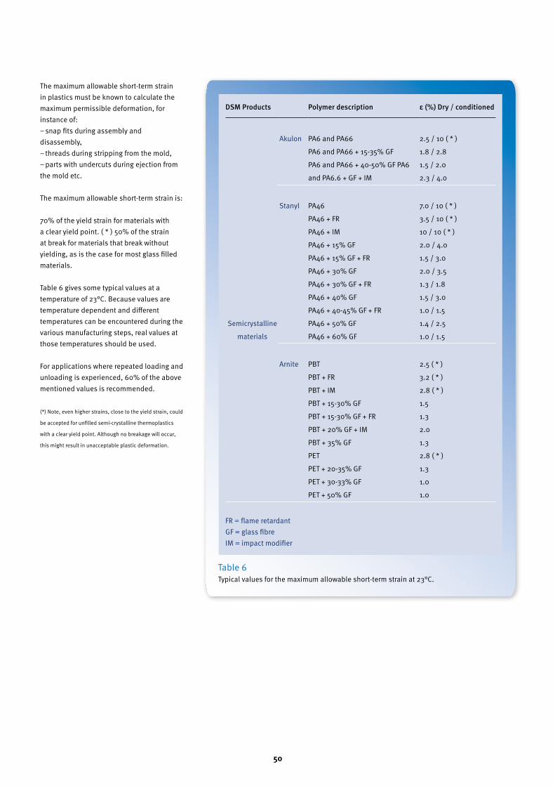
The maximum allowable short-term strain in plastics must be known to calculate the maximum permissible deformation, for instance of:− snap fits during assembly and disassembly,− threads during stripping from the mold,− parts with undercuts during ejection from the mold etc.
The maximum allowable short-term strain is:
70% of the yield strain for materials with a clear yield point. ( * ) 50% of the strain at break for materials that break without yielding, as is the case for most glass filled materials.
Table 6 gives some typical values at a temperature of 23°C. Because values are temperature dependent and different temperatures can be encountered during the various manufacturing steps, real values at those temperatures should be used.
For applications where repeated loading and unloading is experienced, 60% of the above mentioned values is recommended.
(*) Note, even higher strains, close to the yield strain, could
be accepted for unfilled semi-crystalline thermoplastics
with a clear yield point. Although no breakage will occur,
this might result in unacceptable plastic deformation.
Table 6 Typical values for the maximum allowable short-term strain at 23°C.
DSMProducts Polymerdescription ε(%)Dry/conditioned
Akulon PA6 and PA66
PA6 and PA66 + 15-35% GF
PA6 and PA66 + 40-50% GF PA6
and PA6.6 + GF + IM
2.5 / 10 ( * )
1.8 / 2.8
1.5 / 2.0
2.3 / 4.0
Semi crystalline
materials
Stanyl PA46
PA46 + FR
PA46 + IM
PA46 + 15% GF
PA46 + 15% GF + FR
PA46 + 30% GF
PA46 + 30% GF + FR
PA46 + 40% GF
PA46 + 40-45% GF + FR
PA46 + 50% GF
PA46 + 60% GF
7.0 / 10 ( * )
3.5 / 10 ( * )
10 / 10 ( * )
2.0 / 4.0
1.5 / 3.0
2.0 / 3.5
1.3 / 1.8
1.5 / 3.0
1.0 / 1.5
1.4 / 2.5
1.0 / 1.5
Arnite PBT
PBT + FR
PBT + IM
PBT + 15-30% GF
PBT + 15-30% GF + FR
PBT + 20% GF + IM
PBT + 35% GF
PET
PET + 20-35% GF
PET + 30-33% GF
PET + 50% GF
2.5 ( * )
3.2 ( * )
2.8 ( * )
1.5
1.3
2.0
1.3
2.8 ( * )
1.3
1.0
1.0
FR = flame retardantGF = glass fibreIM = impact modifier

51
13 Coefficient of Friction
52
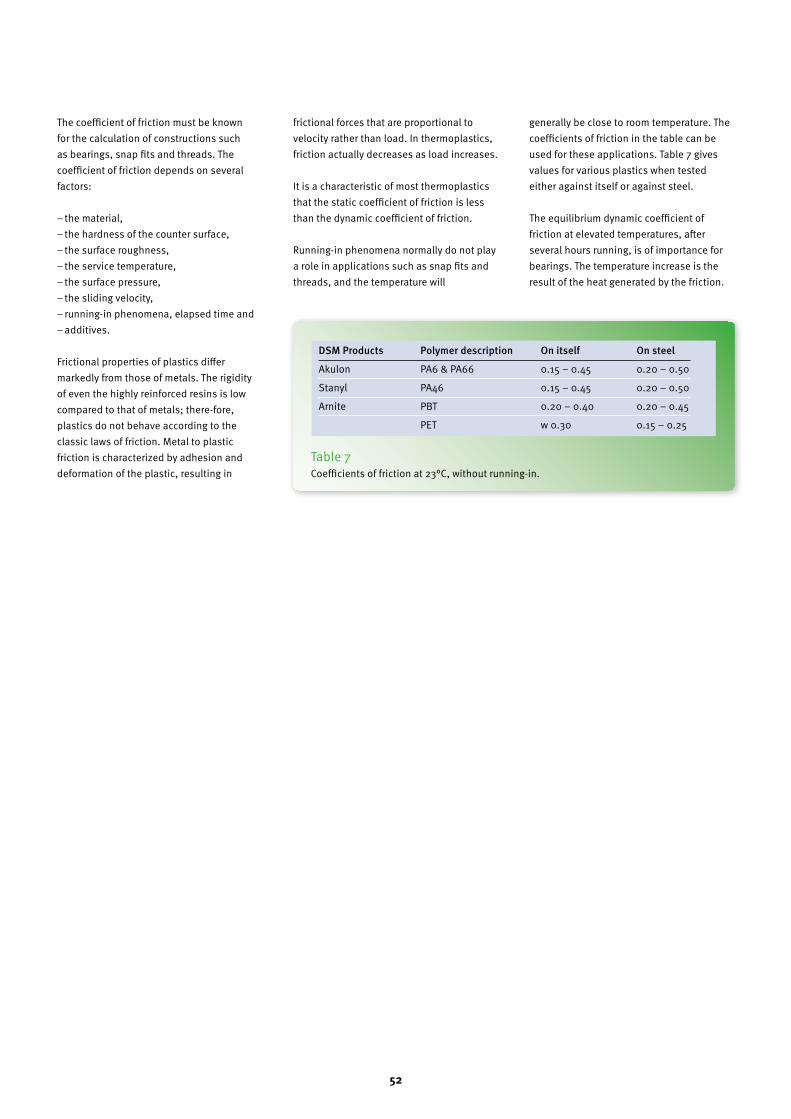
The coefficient of friction must be known for the calculation of constructions such as bearings, snap fits and threads. The coefficient of friction depends on several factors:
− the material,− the hardness of the counter surface,− the surface roughness,− the service temperature,− the surface pressure,− the sliding velocity,− running-in phenomena, elapsed time and− additives.
Frictional properties of plastics differ markedly from those of metals. The rigidity of even the highly reinforced resins is low compared to that of metals; there-fore, plastics do not behave according to the classic laws of friction. Metal to plastic friction is characterized by adhesion and deformation of the plastic, resulting in
frictional forces that are proportional to velocity rather than load. In thermoplastics, friction actually decreases as load increases.
It is a characteristic of most thermoplastics that the static coefficient of friction is less than the dynamic coefficient of friction.
Running-in phenomena normally do not play a role in applications such as snap fits and threads, and the temperature will
generally be close to room temperature. The coefficients of friction in the table can be used for these applications. Table 7 gives values for various plastics when tested either against itself or against steel.
The equilibrium dynamic coefficient of friction at elevated temperatures, after several hours running, is of importance for bearings. The temperature increase is the result of the heat generated by the friction.
Table 7 Coefficients of friction at 23°C, without running-in.
DSMProducts Polymerdescription Onitself Onsteel
Akulon PA6 & PA66 0.15 – 0.45 0.20 – 0.50
Stanyl PA46 0.15 – 0.45 0.20 – 0.50
Arnite PBT 0.20 – 0.40 0.20 – 0.45
PET w 0.30 0.15 – 0.25

53
14 Poisson’s Ratio
54
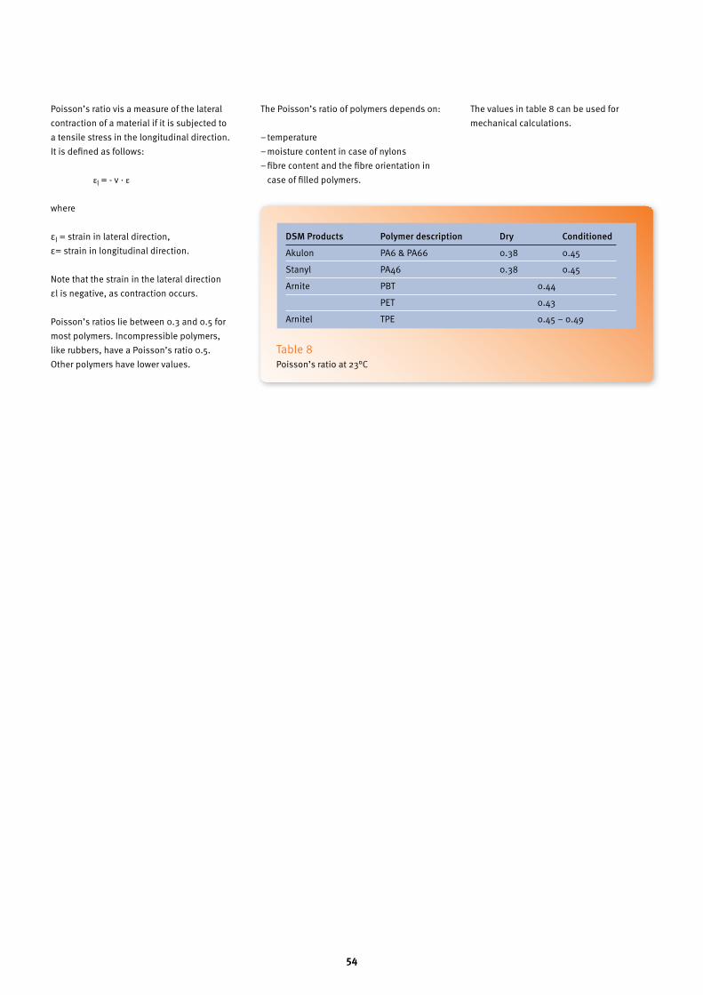
Poisson’s ratio νis a measure of the lateral contraction of a material if it is subjected to a tensile stress in the longitudinal direction. It is defined as follows:
εl = - ν · ε
where
εl = strain in lateral direction,ε= strain in longitudinal direction.
Note that the strain in the lateral direction εl is negative, as contraction occurs.
Poisson’s ratios lie between 0.3 and 0.5 for most polymers. Incompressible polymers, like rubbers, have a Poisson’s ratio 0.5. Other polymers have lower values.
The Poisson’s ratio of polymers depends on:
− temperature− moisture content in case of nylons− fibre content and the fibre orientation in
case of filled polymers.
The values in table 8 can be used for mechanical calculations.
Table 8 Poisson’s ratio at 23°C
DSMProducts Polymerdescription Dry Conditioned
Akulon PA6 & PA66 0.38 0.45
Stanyl PA46 0.38 0.45
Arnite PBT 0.44
PET 0.43
Arnitel TPE 0.45 – 0.49