secure rack modems - wti · srm secure rack modems ... the laws of member states relating to...
TRANSCRIPT

WTI Part No. 14439 Rev. A
SRMSecure Rack Modems
User's Guide

i
Warnings and Cautions:Installation Instructions
Secure Racking
If Secure Racked units are installed in a closed or multi-unit rack assembly, they may require further evaluation by Certification Agencies. The following items must be considered.
1. The ambient within the rack may be greater than room ambient. Installation should be such that the amount of air flow required for safe operation is not compromised. The maximum temperature for the equipment in this environment is 60°C. Consideration should be given to the maximum rated ambient.
2. Installation should be such that a hazardous stability condition is not achieved due to uneven loading.
Input Supply
1. Check nameplate ratings to assure there is no overloading of supply circuits that could have an effect on overcurrent protection and supply wiring.
2. When installing -48 VDC rated equipment, it must be installed only per the following conditions:
A. Connect the equipment to a 48 VDC supply source that is electrically isolated from the alternating current source. The 48 VDC source is to be connected to a 48 VDC SELV source.
B. Input wiring to terminal block must be routed and secured in such a manner that it is protected from damage and stress. Do not route wiring past sharp edges or moving parts.
C. A readily accessible disconnect device, with a 3 mm minimum contact gap, shall be incorporated in the fixed wiring.
Grounding
Reliable earthing of this equipment must be maintained. Particular attention should be given to supply connections when connecting to power strips, rather than direct connections to the branch circuit.
No Serviceable Parts Inside; Authorized Service Personnel Only
Do not attempt to repair or service this device yourself. Internal components must be serviced by authorized personnel only.
• ShockHazard-DoNotEnter
• LithiumBatteryCAUTION:Dangerofexplosionifbatteryisincorrectlyreplaced.Replaceonlywithsameorequivalenttyperecommendedbythemanufacturer.Discardusedbatteriesaccordingtothemanufacturer'sinstructions.

ii
Warnings and Cautions
Disconnect Power
If any of the following events are noted, immediately disconnect the unit from the outlet and contact qualified service personnel:
1. If the power cord becomes frayed or damaged.
2. If liquid has been spilled into the device or if the device has been exposed to rain or water.
Disconnect Power Before Servicing
Before attempting to service or remove this unit, please make certain to disconnect the power supply cable from the power source.
Modem Cables
CAUTION: To reduce the risk of fire, use only No. 26 AWG or larger (e.g., 24 AWG) UL Listed or CSA Certified Telecommunication Line Cord.
iii
Agency Approvals
FCC Part 15 Regulation
This equipment has been tested and found to comply with the limits for a Class A digital device, pursuant to part 15 of the FCC Rules. These limits are designed to provide reasonable protection against harmful interference when the equipment is operated in a commercial environment. This equipment generates, uses, and can radiate radio frequency energy and, if not installed and used in accordance with the instruction manual, may cause harmful interference to radio communications. Operation of this equipment in a residential area is likely to cause harmful interference in which case the user will be required to correct the interference at his own expense.
This device complies with part 15 of the FCC Rules. Operation is subject to the following two conditions: (1) This device may not cause harmful interference, and (2) this device must accept any interference received, including interference that may cause undesired operation
WARNING: Changes or modifications to this unit not expressly approved by the party responsible for compliance could void the user’s authority to operate the equipment
EMC, Safety, and R&TTE Directive Compliance
The CE mark is affixed to this product to confirm compliance with the following European Community Directives:
• CouncilDirective2004/108/ECof15December2004ontheapproximationofthelawsofMemberStatesrelatingtoelectromagneticcompatibility;
and
• CouncilDirective2006/95/ECof12December2006ontheharmonizationofthelawsofMemberStatesrelatingtoelectricalequipmentdesignedforusewithincertainvoltagelimits;
and
• CouncilDirective1999/5/ECof9March1999onradioequipmentandtelecommunicationsterminalequipmentandthemutualrecognitionoftheirconformity.
Industry Canada - EMI Information
This Class A digital apparatus complies with Canadian ICES-003.
Cet appareil numérique de la classe A est conforme à la norme NMB-003 du Canada.
This product meets the applicable Industry Canada technical specifications
The Ringer Equivalence Number is an indication of the maximum number of devices allowed to be connected to a telephone interface. The termination on an interface may consist of any combination of devices subject only to the requirement that the sum of the RENs of all the devices does not exceed five.

iv
Table of Contents
1. Introduction. . . . . . . . . . . . . . . . . . . . . . . . . . . . . . . . . . . . . . . . . . . . . . . . . . . . . . . . . . . . . 1-1
2. UnitDescription. . . . . . . . . . . . . . . . . . . . . . . . . . . . . . . . . . . . . . . . . . . . . . . . . . . . . . . . . . 2-1 2.1. Front Panel . . . . . . . . . . . . . . . . . . . . . . . . . . . . . . . . . . . . . . . . . . . . . . . . . . . . . . . . . . . 2-1 2.2. Back Panel . . . . . . . . . . . . . . . . . . . . . . . . . . . . . . . . . . . . . . . . . . . . . . . . . . . . . . . . . . . 2-2 2.3. Front Panel Button Functions . . . . . . . . . . . . . . . . . . . . . . . . . . . . . . . . . . . . . . . . . . . . . 2-3
3. GettingStarted . . . . . . . . . . . . . . . . . . . . . . . . . . . . . . . . . . . . . . . . . . . . . . . . . . . . . . . . . . 3-1 3.1. Apply Power to the SRM . . . . . . . . . . . . . . . . . . . . . . . . . . . . . . . . . . . . . . . . . . . . . . . . 3-1 3.2. Connect Your PC to the SRM . . . . . . . . . . . . . . . . . . . . . . . . . . . . . . . . . . . . . . . . . . . . . 3-1 3.3. Communicating with the SRM . . . . . . . . . . . . . . . . . . . . . . . . . . . . . . . . . . . . . . . . . . . . 3-2 3.4. Basic Modem Commands . . . . . . . . . . . . . . . . . . . . . . . . . . . . . . . . . . . . . . . . . . . . . . . 3-4 3.5. The WMU Enterprise Management Solution . . . . . . . . . . . . . . . . . . . . . . . . . . . . . . . . . 3-5
4. HardwareInstallation. . . . . . . . . . . . . . . . . . . . . . . . . . . . . . . . . . . . . . . . . . . . . . . . . . . . . 4-1 4.1. Connecting the Power Supply Cables . . . . . . . . . . . . . . . . . . . . . . . . . . . . . . . . . . . . . . 4-1 4.1.1. Connect the SRM to Your Power Supply . . . . . . . . . . . . . . . . . . . . . . . . . . . . . 4-1 4.1.2. Installing the Power Supply Cable Keeper . . . . . . . . . . . . . . . . . . . . . . . . . . . . 4-1 4.1.3. DC Powered Units . . . . . . . . . . . . . . . . . . . . . . . . . . . . . . . . . . . . . . . . . . . . . . . 4-1 4.2. Cable Connection . . . . . . . . . . . . . . . . . . . . . . . . . . . . . . . . . . . . . . . . . . . . . . . . . . . . . . 4-2 4.2.1. Connecting the Network Cable . . . . . . . . . . . . . . . . . . . . . . . . . . . . . . . . . . . . . 4-2 4.2.2. The Modem Port . . . . . . . . . . . . . . . . . . . . . . . . . . . . . . . . . . . . . . . . . . . . . . . . 4-2 4.2.3. The SetUp Ports . . . . . . . . . . . . . . . . . . . . . . . . . . . . . . . . . . . . . . . . . . . . . . . . 4-2 4.2.4. The Phone Line Port . . . . . . . . . . . . . . . . . . . . . . . . . . . . . . . . . . . . . . . . . . . . . 4-2
5. BasicOperation. . . . . . . . . . . . . . . . . . . . . . . . . . . . . . . . . . . . . . . . . . . . . . . . . . . . . . . . . . 5-1 5.1. Communicating with the SRM Unit via Network or Setup Port . . . . . . . . . . . . . . . . . . . 5-1 5.1.1. The Text Interface . . . . . . . . . . . . . . . . . . . . . . . . . . . . . . . . . . . . . . . . . . . . . . . 5-1 5.1.2. The Web Browser Interface . . . . . . . . . . . . . . . . . . . . . . . . . . . . . . . . . . . . . . . . 5-3 5.1.3. Access via Mobile Device . . . . . . . . . . . . . . . . . . . . . . . . . . . . . . . . . . . . . . . . . 5-4 5.2. Configuring the SRM for Common Applications . . . . . . . . . . . . . . . . . . . . . . . . . . . . . . 5-5 5.2.1. Dial-Up Access to a Device Connected to the SRM Modem Port . . . . . . . . . . 5-5 5.2.1.1. Alternate Configuration for Dial-Up Access to Connected Device: . . 5-5 5.2.2. Network Accessible Shared Modem . . . . . . . . . . . . . . . . . . . . . . . . . . . . . . . . . 5-6 5.2.2.1. Alternate Configuration for Network Accessible Modem Application . . . . . . . . . . . . . . . . . . . . . . . . . . . . . . . . . . . . . . 5-6 5.2.3. Dial-Up Access to Outbound SSH/Telnet . . . . . . . . . . . . . . . . . . . . . . . . . . . . . 5-7 5.3. Dialing Commands . . . . . . . . . . . . . . . . . . . . . . . . . . . . . . . . . . . . . . . . . . . . . . . . . . . . . 5-7 5.4. Manual Operation . . . . . . . . . . . . . . . . . . . . . . . . . . . . . . . . . . . . . . . . . . . . . . . . . . . . . . 5-7 5.5. Logging Out of Command Mode . . . . . . . . . . . . . . . . . . . . . . . . . . . . . . . . . . . . . . . . . . 5-7
6. ConfigurationOptions . . . . . . . . . . . . . . . . . . . . . . . . . . . . . . . . . . . . . . . . . . . . . . . . . . . . 6-1 6.1. Configuration Menus . . . . . . . . . . . . . . . . . . . . . . . . . . . . . . . . . . . . . . . . . . . . . . . . . . . 6-1 6.2. Defining System Parameters . . . . . . . . . . . . . . . . . . . . . . . . . . . . . . . . . . . . . . . . . . . . . 6-2 6.2.1. The Real Time Clock and Calendar . . . . . . . . . . . . . . . . . . . . . . . . . . . . . . . . . 6-5 6.2.2. The Serial Port Invalid Access Lockout Feature . . . . . . . . . . . . . . . . . . . . . . . . 6-7 6.2.3. Log Configuration . . . . . . . . . . . . . . . . . . . . . . . . . . . . . . . . . . . . . . . . . . . . . . 6-10 6.2.3.1. The Audit Log and Alarm Log Configuration Options . . . . . . . . . . . 6-10 6.2.3.2. The Temperature Log . . . . . . . . . . . . . . . . . . . . . . . . . . . . . . . . . . . . 6-10 6.2.3.3. Reading, Downloading and Erasing Logs . . . . . . . . . . . . . . . . . . . . 6-11 6.2.4. Callback Security . . . . . . . . . . . . . . . . . . . . . . . . . . . . . . . . . . . . . . . . . . . . . . . 6-12 6.2.5. Scripting Options . . . . . . . . . . . . . . . . . . . . . . . . . . . . . . . . . . . . . . . . . . . . . . . 6-13 6.3. User Accounts . . . . . . . . . . . . . . . . . . . . . . . . . . . . . . . . . . . . . . . . . . . . . . . . . . . . . . . 6-15 6.3.1. Command Access Levels . . . . . . . . . . . . . . . . . . . . . . . . . . . . . . . . . . . . . . . . 6-15 6.3.2. Granting Serial Port Access . . . . . . . . . . . . . . . . . . . . . . . . . . . . . . . . . . . . . . 6-16

Table of Contents
v
6. ConfigurationOptions(continued) 6.4. Managing User Accounts . . . . . . . . . . . . . . . . . . . . . . . . . . . . . . . . . . . . . . . . . . . . . . . 6-17 6.4.1. Viewing User Accounts . . . . . . . . . . . . . . . . . . . . . . . . . . . . . . . . . . . . . . . . . . 6-17 6.4.2. Adding User Accounts . . . . . . . . . . . . . . . . . . . . . . . . . . . . . . . . . . . . . . . . . . 6-17 6.4.3. Modifying User Accounts . . . . . . . . . . . . . . . . . . . . . . . . . . . . . . . . . . . . . . . . 6-19 6.4.4. Deleting User Accounts . . . . . . . . . . . . . . . . . . . . . . . . . . . . . . . . . . . . . . . . . . 6-19 6.5. Modem and Serial Port Configuration . . . . . . . . . . . . . . . . . . . . . . . . . . . . . . . . . . . . . 6-20 6.5.1. Modem Modes . . . . . . . . . . . . . . . . . . . . . . . . . . . . . . . . . . . . . . . . . . . . . . . . 6-20 6.5.2. The Serial Port Configuration Menus . . . . . . . . . . . . . . . . . . . . . . . . . . . . . . . 6-20 6.5.2.1. Serial SetUp Port Parameters . . . . . . . . . . . . . . . . . . . . . . . . . . . . . 6-21 6.5.2.2. Serial Modem Port Parameters . . . . . . . . . . . . . . . . . . . . . . . . . . . . 6-21 6.5.2.3. Internal Modem Parameters. . . . . . . . . . . . . . . . . . . . . . . . . . . . . . . 6-22 6.6. Network Configuration . . . . . . . . . . . . . . . . . . . . . . . . . . . . . . . . . . . . . . . . . . . . . . . . . 6-26 6.6.1. Network Port Parameters . . . . . . . . . . . . . . . . . . . . . . . . . . . . . . . . . . . . . . . . 6-27 6.6.2. Network Parameters . . . . . . . . . . . . . . . . . . . . . . . . . . . . . . . . . . . . . . . . . . . . 6-29 6.6.3. IP Security . . . . . . . . . . . . . . . . . . . . . . . . . . . . . . . . . . . . . . . . . . . . . . . . . . . . 6-34 6.6.3.1. Adding IP Addresses to the Allow and Deny Lists . . . . . . . . . . . . . 6-35 6.6.3.2. Linux Operators and Wild Cards . . . . . . . . . . . . . . . . . . . . . . . . . . . 6-36 6.6.3.3. IP Security Examples . . . . . . . . . . . . . . . . . . . . . . . . . . . . . . . . . . . . 6-36 6.6.4. Static Route . . . . . . . . . . . . . . . . . . . . . . . . . . . . . . . . . . . . . . . . . . . . . . . . . . . 6-37 6.6.5. Domain Name Server . . . . . . . . . . . . . . . . . . . . . . . . . . . . . . . . . . . . . . . . . . . 6-37 6.6.6. SNMP Access Parameters . . . . . . . . . . . . . . . . . . . . . . . . . . . . . . . . . . . . . . . 6-38 6.6.7. SNMP Trap Parameters . . . . . . . . . . . . . . . . . . . . . . . . . . . . . . . . . . . . . . . . . . 6-40 6.6.8. LDAP Parameters . . . . . . . . . . . . . . . . . . . . . . . . . . . . . . . . . . . . . . . . . . . . . . 6-41 6.6.8.1. Adding LDAP Groups . . . . . . . . . . . . . . . . . . . . . . . . . . . . . . . . . . . . 6-43 6.6.8.2 Viewing LDAP Groups . . . . . . . . . . . . . . . . . . . . . . . . . . . . . . . . . . . 6-44 6.6.8.3. Modifying LDAP Groups . . . . . . . . . . . . . . . . . . . . . . . . . . . . . . . . . 6-44 6.6.8.4. Deleting LDAP Groups . . . . . . . . . . . . . . . . . . . . . . . . . . . . . . . . . . . 6-44 6.6.9. TACACS Parameters . . . . . . . . . . . . . . . . . . . . . . . . . . . . . . . . . . . . . . . . . . . . 6-45 6.6.10. RADIUS Parameters . . . . . . . . . . . . . . . . . . . . . . . . . . . . . . . . . . . . . . . . . . . . 6-47 6.6.10.1. Dictionary Support for RADIUS . . . . . . . . . . . . . . . . . . . . . . . . . . . . 6-49 6.6.11. Email Messaging Parameters . . . . . . . . . . . . . . . . . . . . . . . . . . . . . . . . . . . . . 6-50 6.7. Save User Selected Parameters . . . . . . . . . . . . . . . . . . . . . . . . . . . . . . . . . . . . . . . . . 6-51 6.7.1. Restore Configuration . . . . . . . . . . . . . . . . . . . . . . . . . . . . . . . . . . . . . . . . . . . 6-51
7. AlarmConfiguration. . . . . . . . . . . . . . . . . . . . . . . . . . . . . . . . . . . . . . . . . . . . . . . . . . . . . . 7-1 7.1. The Over Temperature Alarms . . . . . . . . . . . . . . . . . . . . . . . . . . . . . . . . . . . . . . . . . . . . 7-2 7.2. The Ping-No-Answer Alarm . . . . . . . . . . . . . . . . . . . . . . . . . . . . . . . . . . . . . . . . . . . . . . 7-4 7.2.1. Ping-No-Answer Notification . . . . . . . . . . . . . . . . . . . . . . . . . . . . . . . . . . . . . . . 7-4 7.2.1.1. Defining Ping No Answer IP Addresses . . . . . . . . . . . . . . . . . . . . . . 7-4 7.2.1.2. Configuring the Ping No Answer Alarm . . . . . . . . . . . . . . . . . . . . . . . 7-6 7.3. The Serial Port Invalid Access Lockout Alarm . . . . . . . . . . . . . . . . . . . . . . . . . . . . . . . . 7-8 7.4. The Power Cycle Alarm . . . . . . . . . . . . . . . . . . . . . . . . . . . . . . . . . . . . . . . . . . . . . . . . 7-10 7.5. The No Dialtone Alarm . . . . . . . . . . . . . . . . . . . . . . . . . . . . . . . . . . . . . . . . . . . . . . . . . 7-11
8. TheStatusScreens. . . . . . . . . . . . . . . . . . . . . . . . . . . . . . . . . . . . . . . . . . . . . . . . . . . . . . . 8-1 8.1. Product Status . . . . . . . . . . . . . . . . . . . . . . . . . . . . . . . . . . . . . . . . . . . . . . . . . . . . . . . . 8-1 8.2. The Network Status Screen . . . . . . . . . . . . . . . . . . . . . . . . . . . . . . . . . . . . . . . . . . . . . . 8-1 8.3. The Port Status Screen . . . . . . . . . . . . . . . . . . . . . . . . . . . . . . . . . . . . . . . . . . . . . . . . . 8-2 8.4. The Port Diagnostics Screen . . . . . . . . . . . . . . . . . . . . . . . . . . . . . . . . . . . . . . . . . . . . . 8-2 8.5. The Alarm Status Screen . . . . . . . . . . . . . . . . . . . . . . . . . . . . . . . . . . . . . . . . . . . . . . . . 8-2 8.6. The Port Parameters Screens . . . . . . . . . . . . . . . . . . . . . . . . . . . . . . . . . . . . . . . . . . . . 8-3 8.7. The Event Logs . . . . . . . . . . . . . . . . . . . . . . . . . . . . . . . . . . . . . . . . . . . . . . . . . . . . . . . . 8-4 8.7.1. The Audit Log . . . . . . . . . . . . . . . . . . . . . . . . . . . . . . . . . . . . . . . . . . . . . . . . . . 8-4 8.7.2. The Alarm Log . . . . . . . . . . . . . . . . . . . . . . . . . . . . . . . . . . . . . . . . . . . . . . . . . . 8-4 8.7.3. The Temperature Log . . . . . . . . . . . . . . . . . . . . . . . . . . . . . . . . . . . . . . . . . . . . 8-4

Table of Contents
vi
9. Telnet&SSHFunctions . . . . . . . . . . . . . . . . . . . . . . . . . . . . . . . . . . . . . . . . . . . . . . . . . . . 9-1 9.1. Network Port Numbers . . . . . . . . . . . . . . . . . . . . . . . . . . . . . . . . . . . . . . . . . . . . . . . . . . 9-1 9.2. SSH Encryption . . . . . . . . . . . . . . . . . . . . . . . . . . . . . . . . . . . . . . . . . . . . . . . . . . . . . . . 9-1 9.3. Creating an Outbound Telnet Connection . . . . . . . . . . . . . . . . . . . . . . . . . . . . . . . . . . . 9-2 9.4. Creating an Outbound SSH Connection . . . . . . . . . . . . . . . . . . . . . . . . . . . . . . . . . . . . 9-3
10.SyslogMessages . . . . . . . . . . . . . . . . . . . . . . . . . . . . . . . . . . . . . . . . . . . . . . . . . . . . . . . 10-1 10.1. Configuration . . . . . . . . . . . . . . . . . . . . . . . . . . . . . . . . . . . . . . . . . . . . . . . . . . . . . . . . 10-1
11.OperationviaSNMP. . . . . . . . . . . . . . . . . . . . . . . . . . . . . . . . . . . . . . . . . . . . . . . . . . . . . 11-1 11.1. SRM SNMP Agent . . . . . . . . . . . . . . . . . . . . . . . . . . . . . . . . . . . . . . . . . . . . . . . . . . . . 11-1 11.2. SNMPv3 Authentication and Encryption . . . . . . . . . . . . . . . . . . . . . . . . . . . . . . . . . . . 11-1 11.3. Configuration via SNMP . . . . . . . . . . . . . . . . . . . . . . . . . . . . . . . . . . . . . . . . . . . . . . . . 11-2 11.3.1. Viewing Users . . . . . . . . . . . . . . . . . . . . . . . . . . . . . . . . . . . . . . . . . . . . . . . . . 11-3 11.3.2. Adding Users . . . . . . . . . . . . . . . . . . . . . . . . . . . . . . . . . . . . . . . . . . . . . . . . . . 11-3 11.3.3. Modifying Users . . . . . . . . . . . . . . . . . . . . . . . . . . . . . . . . . . . . . . . . . . . . . . . . 11-3 11.3.4. Deleting Users . . . . . . . . . . . . . . . . . . . . . . . . . . . . . . . . . . . . . . . . . . . . . . . . . 11-3 11.4. Configuring Serial Ports . . . . . . . . . . . . . . . . . . . . . . . . . . . . . . . . . . . . . . . . . . . . . . . . 11-3 11.5. Viewing Unit Status via SNMP . . . . . . . . . . . . . . . . . . . . . . . . . . . . . . . . . . . . . . . . . . . 11-4 11.5.1. System Status - Ethernet Port Mac Addresses . . . . . . . . . . . . . . . . . . . . . . . . 11-4 11.5.2. Unit Temperature Status . . . . . . . . . . . . . . . . . . . . . . . . . . . . . . . . . . . . . . . . . 11-4 11.5.3. Alarm Status . . . . . . . . . . . . . . . . . . . . . . . . . . . . . . . . . . . . . . . . . . . . . . . . . . 11-4 11.6. Sending Traps via SNMP . . . . . . . . . . . . . . . . . . . . . . . . . . . . . . . . . . . . . . . . . . . . . . . 11-5
12 SettingUpSSLEncryption. . . . . . . . . . . . . . . . . . . . . . . . . . . . . . . . . . . . . . . . . . . . . . . . 12-1 12.1. Creating a Self Signed Certificate . . . . . . . . . . . . . . . . . . . . . . . . . . . . . . . . . . . . . . . . 12-2 12.2. Creating a Signed Certificate . . . . . . . . . . . . . . . . . . . . . . . . . . . . . . . . . . . . . . . . . . . . 12-3 12.3. Downloading the Server Private Key . . . . . . . . . . . . . . . . . . . . . . . . . . . . . . . . . . . . . . 12-4 12.4. TLS Mode . . . . . . . . . . . . . . . . . . . . . . . . . . . . . . . . . . . . . . . . . . . . . . . . . . . . . . . . . . . 12-5
13.SavingandRestoringConfigurationParameters. . . . . . . . . . . . . . . . . . . . . . . . . . . . . . 13-1 13.1. Sending Parameters to a File . . . . . . . . . . . . . . . . . . . . . . . . . . . . . . . . . . . . . . . . . . . . 13-1 13.1.1. Downloading & Saving Parameters via Text Interface . . . . . . . . . . . . . . . . . . 13-1 13.1.2. Downloading & Saving Parameters via Web Browser Interface . . . . . . . . . . . 13-2 13.2. Restoring Downloaded Parameters . . . . . . . . . . . . . . . . . . . . . . . . . . . . . . . . . . . . . . . 13-2 13.3. Restoring Recently Saved Parameters . . . . . . . . . . . . . . . . . . . . . . . . . . . . . . . . . . . . 13-3
14.UpgradingSRMFirmware. . . . . . . . . . . . . . . . . . . . . . . . . . . . . . . . . . . . . . . . . . . . . . . . . 14-1 14.1. WMU Enterprise Management Software (Recommended) . . . . . . . . . . . . . . . . . . . . . 14-1 14.2. The Upgrade Firmware Function (Alternate Method) . . . . . . . . . . . . . . . . . . . . . . . . . 14-1
15.CommandReferenceGuide. . . . . . . . . . . . . . . . . . . . . . . . . . . . . . . . . . . . . . . . . . . . . . . 15-1 15.1. Command Conventions . . . . . . . . . . . . . . . . . . . . . . . . . . . . . . . . . . . . . . . . . . . . . . . . 15-1 15.2. Command Summary . . . . . . . . . . . . . . . . . . . . . . . . . . . . . . . . . . . . . . . . . . . . . . . . . . 15-2 15.3. Command Set . . . . . . . . . . . . . . . . . . . . . . . . . . . . . . . . . . . . . . . . . . . . . . . . . . . . . . . 15-3 15.3.1. Display Commands . . . . . . . . . . . . . . . . . . . . . . . . . . . . . . . . . . . . . . . . . . . . . 15-3 15.3.2. Control Commands . . . . . . . . . . . . . . . . . . . . . . . . . . . . . . . . . . . . . . . . . . . . . 15-6 15.3.3. Configuration Commands . . . . . . . . . . . . . . . . . . . . . . . . . . . . . . . . . . . . . . . . 15-9
Appendices:
A. Specifications. . . . . . . . . . . . . . . . . . . . . . . . . . . . . . . . . . . . . . . . . . . . . . . . . . . . . . . . .Apx-1
B. InterfaceDescriptions. . . . . . . . . . . . . . . . . . . . . . . . . . . . . . . . . . . . . . . . . . . . . . . . . . .Apx-2
C. CustomerService. . . . . . . . . . . . . . . . . . . . . . . . . . . . . . . . . . . . . . . . . . . . . . . . . . . . . .Apx-4

Table of Contents
vii
List of Figures
2.1. Front Panel . . . . . . . . . . . . . . . . . . . . . . . . . . . . . . . . . . . . . . . . . . . . . . . . . . . . . . . . . . . . . 2-12.2. Back Panel . . . . . . . . . . . . . . . . . . . . . . . . . . . . . . . . . . . . . . . . . . . . . . . . . . . . . . . . . . . . . . 2-24.1. Terminal Block Assembly (DC Units Only) . . . . . . . . . . . . . . . . . . . . . . . . . . . . . . . . . . . . . 4-112.1. Web Access Parameters (Text Interface Only) . . . . . . . . . . . . . . . . . . . . . . . . . . . . . . . . . 12-1B.1. RJ45 SetUp Port (DTE) . . . . . . . . . . . . . . . . . . . . . . . . . . . . . . . . . . . . . . . . . . . . . . . . . . Apx-2B.2. DB25 Modem Port (DCE) . . . . . . . . . . . . . . . . . . . . . . . . . . . . . . . . . . . . . . . . . . . . . . . . Apx-2B.3. RJ45 Modem Port (DCE) . . . . . . . . . . . . . . . . . . . . . . . . . . . . . . . . . . . . . . . . . . . . . . . . . Apx-2B.4. RJ11 Phone Line Port . . . . . . . . . . . . . . . . . . . . . . . . . . . . . . . . . . . . . . . . . . . . . . . . . . . Apx-3
1-1
1. Introduction
The SRM Secure Rack Modem is designed for applications that require secure, dial-up access to remote, rack mounted network elements. In addition to password security and a multi-level user directory, the SRM also supports SSHv2 encryption, IP address filtering and HTTPS/SSL Secure web, plus popular authentication protocols such as LDAP, Kerberos, TACACS+ and RADIUS.
In order to simplify the process of configuring and managing modem functions, administrators can access the SRM via Ethernet Port, RJ45 Serial port or USB Mini Port. A convenient logging function tracks user activity, alarms, rack temperatures and other factors to provide administrators with an audit trail of events and environmental conditions.
Security and Co-Location Features:
Secure Shell (SSHv2) encryption and address-specific IP security masks help to prevent unauthorized access to command and configuration functions.
The SRM provides four different levels of security for user accounts: Administrator, SuperUser, User and ViewOnly. The Administrator level provides complete access to all serial port and switched plug functions, status displays and configuration menus. The SuperUser level allows control of serial ports and plugs, but does not allow access to configuration functions. The User level allows access to only a select group of Administrator-defined serial ports and plugs. The ViewOnly level allows you to check unit status, but does not allow control of serial ports or switched outlets or access to configuration menus.
WTI Management Utility
SRM units include the WTI Enterprise Management Utility (WMU,) which allows you to manage multiple WTI units via a single menu. For more information on the Enterprise Management Utility, please refer to the WMU User’s Guide, which can be downloaded from the WTI web site at: http://www.wti.com/t-product-manuals.aspx.

1-2
Introduction
Typographic Conventions
^ (e.g. ^X) Indicates a control character. For example, the text "^X" (Control X) indicates the [Ctrl] key and the [X] key must be pressed simultaneously.
COURIER FONT Indicates characters typed on the keyboard. For example, /RB or /ON 2.
[BoldFont] Text set in bold face and enclosed in square brackets, indicates a specific key. For example, [Enter] or [Esc].
< > Indicates required keyboard entries: For Example: /P <n>.
[ ] Indicates optional keyboard entries. For Example: /P [n].

2-1
2. Unit Description
2.1. Front Panel
As shown in Figure 2.1, the SRM front panel includes the following components:
RESET: Can be used to restart the SRM operating system as described in Section 2.3.
DEFAULT: Can be used to initialize the SRM to default parameters as described in Section 2.3.
ON: Lights when AC Power is applied.
à RDY: (Ready) Flashes when the unit is ready to receive commands.
ModemStatusIndicators: Four LEDs which function as follows:
• DCD: (Data Carrier Detect) Lights when the DCD signal is present.
• RXD: (Recieve Data) Lights when the RXD signal is present.
• DTR: (Data Terminal Ready) Lights when the DTR signal is present.
• TXD: (Transmit Data) Lights when the TXD signal is present.
SetUpPortActivityLED: Lights when the SetUp Port (Console Port) is active.
ModemPortActivityLED: Lights when the Modem Port is active.
Dialtone: Lights when a dialtone is detected.
STATUSMODEMSTATUS
PORTACTIVITY STATUS
ON RDY DCD SETUP MODEM DIALTONERXD DTR TXDDEFRST
www.wti.com
SRM
Secure Rack Modem
1 2 3 4 5 6 7 8
Figure 2.1: Front Panel

2-2
Unit Description
2.2. Back Panel
As shown in Figure 2.2, the SRM Back Panel includes the following components:
PowerInlet: An IEC-320-C14 inlet, for connection to your 100 to 240 VAC power supply.
Note: 48 VDC powered models include a terminal block assembly (see Figure 4.1) in place of the power inlet. For more information, please refer to Section 4.1.3.
SwitchedContact: A dry contact that can be connected to an external alarm unit. When an external alarm unit is connected to the Switched Contact, the alarm unit will be activated when the No Dialtone Alarm is triggered. For more information on the No Dialtone Alarm, please refer to Section 7.5. The switched contact includes three pins: A Normally Closed (NC) pin, a Common (COM) pin and a Normally Open (NO) pin. The switched contact is rated for 2 Amps maximum.
SetUpPorts: A USB Mini Port and an RJ45 Serial Port that can be used to connect a local device to the SRM unit as described in Section 4.2. For a description of the Setup Port interface, please refer to Appendix B.
à ModemPorts: An RJ45 RS232 serial port (DCE configuration) and a DB25 serial port that can be used for connection to a PC or tablet.
NetworkPort: An RJ45 Ethernet port for connection to your 10/100Base-T, TCP/IP network. Note that the SRM features a default, IPv4 format IP address (192.168.168.168). This allows you to connect to the unit without first assigning an IP address. Note that the Network Port also includes two, small LED indicators for Link and Data Activity. For more information on Network Port configuration, please refer to Section 6.6.
PhoneLinePort: The phone line port is used for connection to your external phone line.
Ethernet RJ11
PHONEACT LINK
100 - 120V ~ 50/60 Hz 0.2A
SETUP PORT MODEM PORT
USB MININC NOCOM
NC NOCOM
SERIAL RJ45 DB25
1 2 3 4 5 6
Figure 2.2: Back Panel

2-3
Unit Description
2.3. Front Panel Button Functions
The front panel buttons can be used to perform several functions described below:
Notes:• FrontPanelbuttonfunctionscanalsobedisabledviatheSystemParameters
menu, as described in Section 6.2.
• WhentheSRMisresettofactorydefaults,alluser-definedconfigurationparameters will be cleared and the default “super” user account will also be restored.
• Duringtherebootprocedure,allportactivityLEDswillflashonce.
1. RebootOperatingSystem-KeepUser-DefinedParameters:
a) Press and hold the CLEAR (or RESET) button for five seconds, and then release.
b) The SRM operating system will reboot; all user-defined parameters will be retained.
2. RebootOperatingSystem-ResetAllParameterstoFactoryDefaults:
a) Simultaneously press both the SET (or DEFAULT) button and the CLEAR (or RESET) button, hold them for five seconds, and then release.
b) The SRM operating system will reboot; all user-defined parameters will be reset to factory default settings.
Note:TheRDYIndicatorwillcontinuetoblinkforabout45secondswhileparametersarebeingerasedandkeysarerebuilt.TheRDYIndicatorwillthenstop blinking during the reboot.

3-1
3. Getting Started
This section describes a simplified installation procedure for the SRM hardware, which will allow you to communicate with the unit in order to demonstrate basic features and check for proper operation. Note that this Quick Start procedure does not provide a detailed description of unit configuration, or discuss advanced operating features in detail. For more information, please refer to the remainder of this User’s Guide.
3.1. Apply Power to the SRM
Refer to the safety precautions listed at the beginning of this User's Guide, and then connect the unit to an appropriate power source. Connect the power supply cable to the unit’s power inlet, snap the Cable Keeper into place, and then connect the cable to an appropriate power supply. Please refer to the power rating label on the unit concerning power requirements and maximum load.
When power is applied to the SRM, the ON LED on the instrument front panel should light, and the RDY LED should begin to flash within 90 seconds. This indicates that the unit is ready to receive commands.
3.2. Connect Your PC to the SRM
The SRM can either be controlled via local PC Serial Port, USB Mini Port, modem, or TCP/IP network. In order to connect ports or select parameters, commands are issued to the SRM via either the Network Port, Modem or Setup Port. Note that it is not necessary to connect to both the Network and Setup Ports.
• NetworkPort: Connect your network interface to the SRM's Network port.
• SetUpPort: Connect your PC COM Port to either the RJ45 Serial SetUp Port or USB Mini Port.
► RJ45SetUpPort: When connecting to the RJ45 SetUp Port, use the supplied DX9F-DTE-RJ adapter and RJ45 Ethernet cable to connect your PC COM port to the SRM's SetUp Port (Serial Port 1.) For a description of the RJ45 SetUp Port, please refer to Figure B.1.
► USBMiniSetUpPort: When connecting to the USB Mini Port, use a standard USB Mini Port cable.
• ModemPort: The Modem Port includes both a DB25 Connector and an RJ45 connector. Note that both ports cannot be used at the same time. In the default state the Modem is connected to the Modem Port.
► DB25ModemPort: When connecting a PC or other device to the DB25 Modem Port use a standard Modem Cable. For pinout, see Figure B.2.
► RJ45ModemPort: When connecting a PC or other device to the RJ45 connector, use a standard Ethernet patch cable. For pinout, see Figure B.3.
• PhoneLine:Connect your phone line to the SRM’s RJ11 Phone Line Port. For a description of the RJ11 Phone Line Port pinout, please refer to Figure B.4.

3-2
Getting Started
3.3. Communicating with the SRM
The SRM command mode can be used to configure the unit's internal modem, selected communication parameters, define user accounts and to perform other unit management related functions. When properly installed and configured, the SRM will allow command mode access via Telnet, Web Browser, SSH client, modem, or local PC. However, in order to ensure security, both Telnet and Web Browser access are disabled in the default state. To enable Telnet and/or Web Browser access, please refer to Section 6.6.2.
Notes:• DefaultSRMserialportparametersaresetasfollows:9600bps,RTS/CTSHandshaking,8DataBits,OneStopBit,NoParity.Althoughtheseparameters can be easily redefined, for this Quick Start procedure, it is recommended to configure your communications program to accept the default parameters.
• TheSRMfeaturesadefaultIPAddress(192.168.168.168)andadefaultSubnetMask(255.255.255.0.)Thisallowsnetworkaccesstocommandmode,providingthatyouarecontactingtheSRMfromanodeonthesamesubnet.WhenattemptingtoaccesstheSRMfromanodethatisnotonthesame subnet, please refer to Section 6.6 for further configuration instructions.
• WhenconnectingonlyasinglenetworkcabletoaSRMunitthatincludestwoEthernetports,makecertaintoconnecttoPortETH0(theupperEthernetPort.)
1. AccessCommandMode:The SRM includes two separate user interfaces; the Text Interface and the Web Browser Interface. The Text Interface is available via Local PC, SSH Client, or Telnet and can be used to both configure the SRM and create connections between ports. The Web Browser interface is only available via TCP/IP network, and can be used to configure the unit, but cannot create connections between ports.
a) ViaSetUpPort: Start your communications program, then select the appropriate COM port and press [Enter]. Note that when viewed by a PC running Windows XP or later, the Serial COM Port menu will list the USB Mini Port as, "USB to Serial."
b) ViaSSHClient: Start your SSH client, enter the default IP address (192.168.168.168) for the SRM and invoke the connect command.
c) ViaWebBrowser: Make certain that Web Browser access is enabled as described in Section 6.6.2. Start your JavaScript enabled Web Browser, enter the default IPv4 format SRM IP address (192.169.168.168) in the Web Browser address bar, and then press [Enter].
d) ViaTelnet: Make certain that Telnet access is enabled as described in Section 6.6.2. Start your Telnet client, and enter the SRM's default IPv4 format IP address (192.168.168.168).

3-3
Getting Started
2. Username/PasswordPrompt: A message will be displayed, which prompts you to enter your username (Login) and password.. The default username is "super" (all lower case, no quotes), and the default password is also "super". If a valid username and password are entered, the SRM will display either the Main Menu (Web Browser Interface) or the Port Status Screen (SSH, Telnet, or Modem.)
Notes:• ThedefaultUsernameis"super".
• ThedefaultPasswordis"super"
• IfaLoginBannerhasbeendefinedasdescribedinSection6.2,thenabanner page will appear before the command interface is displayed. The LoginBannercanbeusedtodisplaylegalwarningsorotherinformation.
3. ReviewHelpMenu: If you are communicating with the SRM via the text interface (SSH, Telnet or Modem), type /H and press [Enter] to display the Help Menu, which lists all available SRM commands. Note that the Help Menu is not available via the Web Browser Interface.

3-4
Getting Started
3.4. Basic Modem Commands
This section describes basic Modem AT commands that can be used to demonstrate basic modem capabilities. For a complete list of available modem commands, please refer to the AT Command Reference Guide, which can be found in WTI's online User's Guide Archive at: http://www.wti.com/t-product-manuals.aspx
AT Attention command. Must be included as a prefix for all commands unless otherwise noted.
+++ Switches Modem from data mode to command mode. This command is not proceeded by the AT command. The +++ command can be used in conjeunction with the Hn command to disconnect a session. To disconnect, enter the +++ comand followed by a one second delay, type ATH and then press [Enter] (e.g., +++ ATH [Enter])
A Tells the modem to attempt to answer an incoming call. (e.g., ATA)
Dn Causes the modem to dial the number n. Offers the following command options: T (Tone Dialing,) P (Pulse dialing,) - (Pause 2 seconds,) @ (Wait for 5 seconds of silence,) L (Call last number dialed.) (e.g., ATD 5551212)
En Toggles command echo On/Off. Allows commands to either be displayed or hidden (0 = Off, 1 = On.) (e.g., ATE1)
Hn When data mode is active, this command instructs modem to hang up or pick up (0 = hang up, 1 = pick up.) (e.g., ATH1)
Qn Displays/hides result codes. (0 = Display result codes, 1 = Hide Result codes.)(e.g., ATQ1)
S0=n Number of rings to answer. (e.g., ATS0=1 will cause the modem to answer on the first ring.)
Z Soft Reset. Restores basic defaults. (e.g., ATZ)
&Fn Resets modem to factory settings. (0 = Fetch default configuration, 1 = Recall factory default configuration, 2 = Recall Sierra factory default for auto.)(e.g., AT&F1)

3-5
Getting Started
3.5. The WMU Enterprise Management Solution
The WMU Enterprise Management Solution provides a centralized interface that can be used to configure, manage and control multiple WTI out-of-band management devices spread throughout a large corporate network infrastructure. When installed at your network operation center or support facility, the WMU eliminates the need to individually access WTI units in order to perform firmware updates, edit user accounts and perform other management and control functions.
The WMU software and user's guide can be downloaded at:
ftp://wtiftp.wti.com/pub/TechSupport/WMU/WtiManagementUtilityInstall.exe
This completes the Quick Start procedure for the SRM. Prior to placing the unit into operation, it is recommended to refer to the remainder of this user’s guide for important information regarding advanced configuration capabilities and more detailed operation instructions. If you have further questions regarding the SRM unit, please contact WTI Customer Support as described in Appendix C.
4-1
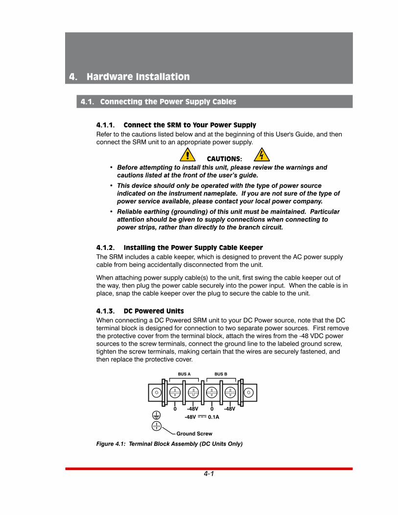
4. Hardware Installation
4.1. Connecting the Power Supply Cables
4.1.1. Connect the SRM to Your Power SupplyRefer to the cautions listed below and at the beginning of this User's Guide, and then connect the SRM unit to an appropriate power supply.
CAUTIONS:• Beforeattemptingtoinstallthisunit,pleasereviewthewarningsand
cautions listed at the front of the user’s guide.
• Thisdeviceshouldonlybeoperatedwiththetypeofpowersourceindicated on the instrument nameplate. If you are not sure of the type of powerserviceavailable,pleasecontactyourlocalpowercompany.
• Reliableearthing(grounding)ofthisunitmustbemaintained.Particularattentionshouldbegiventosupplyconnectionswhenconnectingtopowerstrips,ratherthandirectlytothebranchcircuit.
4.1.2. Installing the Power Supply Cable KeeperThe SRM includes a cable keeper, which is designed to prevent the AC power supply cable from being accidentally disconnected from the unit.
When attaching power supply cable(s) to the unit, first swing the cable keeper out of the way, then plug the power cable securely into the power input. When the cable is in place, snap the cable keeper over the plug to secure the cable to the unit.
4.1.3. DC Powered UnitsWhen connecting a DC Powered SRM unit to your DC Power source, note that the DC terminal block is designed for connection to two separate power sources. First remove the protective cover from the terminal block, attach the wires from the -48 VDC power sources to the screw terminals, connect the ground line to the labeled ground screw, tighten the screw terminals, making certain that the wires are securely fastened, and then replace the protective cover.
-48V
-48V -48V00
0.1A
BUS A BUS B
Ground Screw
Figure4.1:TerminalBlockAssembly(DCUnitsOnly)

4-2
Hardware Installation
4.2. Cable Connection
4.2.1. Connecting the Network CableThe Network Port is an RJ45 Ethernet jack, for connection to a TCP/IP network. Connect your 100Base-T cable to the Network Port. Note that the SRM includes a default IPv4 protocol IP address (192.168.168.168) and a default IPv4 protocol subnet mask (255.255.255.0.) When installing the SRM in a working network environment, it is recommended to define network parameters as described in Section 6.6.
4.2.2. The Modem PortThe Modem Port includes both a DB25 Connector and an RJ45 connector. Note that both ports cannot be used at the same time. In the default state the internal Modem is connected to the Modem Port. For a description of the Modem Port pinout, please refer to Appendix B.
• DB25ModemPort: When connecting a PC or other device to the DB25 Modem Port use a standard Modem Cable. For pinout, see Figure B.2.
• RJ45ModemPort: When connecting a PC or other device to the RJ45 connector, use a standard Ethernet patch cable. For pinout, see Figure B.3.
4.2.3. The SetUp PortsIn order to select configuration parameters and review unit status, commands are issued to the SRM via either the Network Port or Setup Port. Note that it is not necessary to connect to both the Network and Setup Ports. Connect your PC COM Port to either the RJ45 format Serial SetUp Port or USB Mini format SetUp Port. For a description of the RJ45 SetUp Port pinout, please refer to Appendix B.
• RJ45SetUpPort: When connecting to the RJ45 SetUp Port, use the supplied DX9F-DTE-RJ adapter and RJ45 Ethernet cable to connect your PC COM port to the SRM's SetUp Port (Serial Port 1.)
• USBMiniSetUpPort: When connecting to the USB Mini Port, use a standard USB Mini Port cable.
4.2.4. The Phone Line PortConnect your RJ11 phone line to the RJ11 Phone line connector. For information on Modem configuration, please refer to Section 6.5.2.3. For a description of the Phone Line Port pinout, please refer to Appendix B.
This completes the SRM installation instructions. Please proceed to the next Section for instructions regarding basic unit configuration.

5-1
5. Basic Operation
5.1. Communicating with the SRM Unit via Network or Setup Port
In order to configure the SRM, you must connect to the unit via Network or Setup Port, and access command mode. Note that, the SRM offers two separate configuration interfaces; the Web Browser Interface and the Text Interface. The Web Browser interface is only available via network, and the Text Interface is available via network (SSH or Telnet) or local PC.
Notes:• InordertoaccesstheSRMcommandmodeviamodem,youmustfirstdisablethePasswordBypassandModemPassthroughparametersasdescribedinSection6.5.2.3.
• IfthePasswordBypassandModemPassthroughparametersaredisabled,refertoSection5.2.1.1forinstructionsregardingdial-upaccesstoadeviceattachedtotheSRM'sSerialModemPort.
5.1.1. The Text InterfaceThe Text Interface (also known as the "Command Line Interface" or "CLI") consists of a series of simple ASCII text menus, which allow you to set options and define parameters by entering the number for the desired option using your keyboard, and then typing in the value for that option.
For security purposes, the Web Browser Interface and Telnet accessibility are both disabled in the default state, therefore in order to access command mode functions via Telnet or Web Browser, you will need to use the Text Interface to contact the unit via Local PC or SSH connection when setting up the unit for the first time. After accessing command mode using the Text Interface, you can then enable Web Access and Telnet Access as described in Section 6.6.2, in order to allow future communication with the unit via Web Browser or Telnet. You will not be able to contact the unit via Web Browser or Telnet until you have enabled those options.
Once Telnet Access is enabled, you will then be able to use the Text Interface to communicate with the SRM via local PC, Telnet or SSH connection.
In order to use the Text Interface, your installation must include:
• AccessviaNetwork: The SRM must be connected to your TCP/IP Network, and your PC must include a communications program (such as HyperTerminal, TeraTerm, Putty or a similar terminal emulation program.)
• AccessviaLocalPC: Your PC must be connected to one of the SRM's two available SetUp Ports, the SetUp Port must be configured for Any-to-Any Mode (default,) and your PC must include a communications program (such as HyperTerminal, TeraTerm, Putty or a similar terminal emulation program.)

5-2
Basic Operation
To access command mode via the Text Interface, proceed as follows:
Note: Whencommunicatingwiththeunitforthefirsttime,youwillnotbeabletocontacttheunitviaTelnetuntilyouhaveaccessedcommandmode,viatheSRM'sSetUpport,andusedtheNetworkParametersMenutoenableTelnetasdescribed in Section 6.6.2.
1. Contact the SRM Unit:
a) ViaLocalPC: Start your communications program and press [Enter]. Wait for the connect message, then proceed to Step 2. Note that when viewed by a PC running Windows XP or later, the Serial COM Port menu will list the USB Mini Port as, "USB to Serial."
b) ViaNetwork: The SRM includes a default IPv4 format IP address (192.168.168.168) and a default IPv4 format subnet mask (255.255.255.0.) This allows you to contact the unit from any network node on the same subnet, without first assigning an IP Address to the unit. For more information, please refer to Section 6.6.
i. ViaSSHClient: Start your SSH client, and enter the SRM’s IP Address. Invoke the connect command, wait for the connect message, then proceed to Step 2.
ii. ViaTelnet: Start your Telnet Client, and then Telnet to the SRM’s IP Address. Wait for the connect message, then proceed to Step 2.
c) ViaModem: Use your communications program to dial the number for the phone line that you have connected to the SRM's Modem Port. When a dial-up connection is established,
2. Login/PasswordPrompt: A message will be displayed, which prompts you to enter a username (login name) and password. The default username is "super" (all lower case, no quotes), and the default password is also "super".
Note:IfaLoginBannerhasbeendefinedasdescribedinSection6.2,thenabannerpagewillappearbeforethecommandpromptisdisplayed.TheLoginBanner can be used to display legal warnings or other information.

5-3
Basic Operation
5.1.2. The Web Browser InterfaceThe Web Browser Interface consists of a series of web forms, which can be used to select configuration parameters by selecting buttons and/or entering text into designated fields.
Note:InordertousetheWebBrowserInterface,WebAccessmustfirstbeenabledviatheTextInterfaceNetworkParametersMenu(/N),theSRMmustbeconnectedtoaTCP/IPnetwork,andyourPCmustbeequippedwithaJavaScriptenabledwebbrowser.
1. Start your JavaScript enabled Web Browser, key the SRM’s default IPv4 format IP address (192.168.168.168) into the web browser’s address bar, and press [Enter].
2. Username/PasswordPrompt: A message box will prompt you to enter your username and password. The default username is "super" (all lower case, no quotes), and the default password is also "super".
Note:IfaLoginBannerhasbeendefinedasdescribedinSection6.2,thenabannerpagewillappearbeforethecommandpromptisdisplayed.TheLoginBanner can be used to display legal warnings or other information.

5-4
Basic Operation
5.1.3. Access via Mobile DeviceIn addition to the Web Browser Interface and Text Interface, the SRM command mode can also be accessed by mobile devices. Note however, that due to nature of most mobile devices, only a limited selection of SRM operating and status display functions are available to users who communicate with the unit via mobile device.
When the SRM is operated via a Mobile device, only the following functions are available:
• ProductStatusScreen(UnitInfo)(Section8.1)• PortStatusScreen(Section8.3)
Note: MobiledeviceusersarenotallowedtochangeorreviewSRMconfiguration parameters.
For more information on these functions, please refer to the appropriate section listed next to each function in the list above.
To configure the SRM for access via mobile device, first consult your IT department for appropriate settings. Access the SRM command mode via the Text Interface or Web Browser interface as described in this section, then configure the SRM's Network Port accordingly, as described in Section 6.6.
In most cases, this configuration will be adequate to allow communication with most mobile devices. Note however, that if you wish to use a BlackBerry® to contact the SRM, you must first make certain to configure the BlackBerry to support HTML tables, as described below:
1. Power on the BlackBerry, and then click on the BlackBerry Internet Browser Icon.
2. Press the Menu button, and then choose "Options."
3. From the Options menu, choose "Browser Configuration," then verify to make certain that "Support HTML Tables" is checked (enabled.)
4. Press the Menu button, and select "Save Options."
When you have finished communicating with the SRM via mobile device, it is important to always close the session using the mobile device's menu functions, rather than by simply closing the browser window, in order to ensure that the SRM has completely exited from command mode, and is not waiting for the inactivity timeout period to elapse. For example, to close a session on a BlackBerry, press the Menu button and then choose "Close."

5-5
Basic Operation
5.2. Configuring the SRM for Common Applications
Depending on the configuration parameters selected, the SRM can be used for the following types of applications:
• Dial-UpAccesstoaDeviceConnectedtotheModemPort
• NetworkAccessibleSharedModem
• Dial-UpAccesstoOutboundSSH/Telnet
The sections that follow describe both the configuration requirements and procedure used for employing the SRM in each of these three applications.
Note:ForfurtherinstructionsregardingconfiguringSRMModemparameters,pleaserefertoSection6.5.2.3.
5.2.1. Dial-Up Access to a Device Connected to the SRM Modem PortThe most common application for the SRM is to provide remote, dial-up access to a managed device connected to the SRM's Modem Port. In the event of a network outage, dial-up access provides support personnel with an out-of-band avenue for communication that can be used to access command functions on the managed device in order to restore network communication. In the default state, SRM Modem parameters are set to allow dial-up communication to a device connected to the Modem port.
If you have previously altered the configuration of the SRM, then parameters for the SRM's internal modem should be set as follows in order to allow dial-up access to a device connected to the SRM Modem Port:
Note:ForfurtherinstructionsregardingconfiguringSRMModemparameters,pleaserefertoSection6.5.2.3.
• PasswordBypass=On(default.)
• ModemPassthrough=On(default.)
5.2.1.1. Alternate Configuration for Dial-Up Access to Connected Device:If your application requires the Password Bypass and Modem Passthrough parameters to be disabled, the following procedure can be used to allow dial-up access to a device connected to the SRM Modem Port:
1. Disable both the Password Bypass and Modem Passthrough parameters as described in Section 6.5.2.3.
2. Dial-in to the SRM unit. When the login prompt appears, enter a valid username and password.
3. When the SRM command prompt appears, type /C MODEM and press [Enter] to connect to the device that is attached to the SRM Modem Port.
4. When you have finished communicating with the device attached to the SRM, type ^X ([Ctrl] plus [X]) to return to SRM command mode. Then type /X and press [Enter] to exit the modem session.
5-6
Basic Operation
5.2.2. Network Accessible Shared ModemThe second most common application for the SRM is to serve as a network accessible shared modem. This type of application provides users who do have network access but don't have a modem with network access to the SRM's dial-up functions.
Note:ForfurtherinstructionsregardingconfiguringSRMModemparameters,pleaserefertoSection6.5.2.3.
In order for the SRM to serve as a network accessible, shared Modem, SRM parameters should be set as follows:
• PasswordBypass=Off.
• ModemPassthrough=Off.
5.2.2.1. Alternate Configuration for Network Accessible Modem ApplicationIf your application requires the Password Bypass and Modem Passthrough parameters to be enabled, the following procedure can be used to allow the SRM to serve as a network accessible Modem:
1. Enable both the Password Bypass and Modem Passthrough parameters as described in Section 6.5.2.3.
2. Establish a network connection to the SRM unit. When the login prompt appears, enter a valid username and password.
3. When the SRM command prompt appears, type /D MODEM [Enter] to disconnect the Modem from the Serial Modem Port.
4. Type /C MODEM [Enter] to connect the network port to the SRM's internal Modem. When the connection is established, AT commands can be used to dial-out from the SRM's internal Modem as described in Section 3.4.
5. When you have finished using the Modem, type /X and press [Enter] to exit from AT command mode. When the SRM command prompt appears, type /C 2 3 and press [Enter] to reconnect the Modem to the Serial Modem Port.

5-7
Basic Operation
5.2.3. Dial-Up Access to Outbound SSH/TelnetThis application allows users to dial-in to the SRM unit, and then create an outbound SSH or Telnet connection to other devices on the network where the SRM resides. In cases where a device on at a remote site has malfunctioned and disrupted external network communication with the site, an outbound SSH connection initiated via a dial-up connection to the SRM can be used to communicate with the malfunctioning device in order to restore normal operation.
In order for the SRM to provide dial-up access to outbound SSH/Telnet connections at a remote site, SRM parameters should be set as follows:
Note:ForfurtherinstructionsregardingconfiguringSRMModemparameters,pleaserefertoSection6.5.2.3.
• PasswordBypass=Off.
• ModemPassthrough=Off.
When the Password Bypass and Modem Passthrough parameters disabled, users can dial-in to the SRM unit to access the SRM command mode and then initiate an outbound SSH/Telnet connection as described in Section 9.3 and Section 9.4.
Note:InordertoestablishanoutboundSSH/Telnetconnection,OutboundAccessmustbeenabledforyouruseraccountasdescribedinSection6.4.2.Inaddition,TelnetAccessandOutboundAccessmustalsobeenabledviatheNetworkParametersmenuasdescribedinSection6.6.2.
5.3. Dialing Commands
When the SRM's AT command mode is active, common AT commands can be used to initiate dial-out operations or change basic Modem configuration parameters as described in Section 3.4.
5.4. Manual Operation
In addition to the command driven functions available via the Web Browser Interface and Text Interface, some SRM functions can also be controlled manually. For a summary of front panel control functions, please refer to Section 2.3.
5.5. Logging Out of Command Mode
When you have finished communicating with the SRM, it is important to always disconnect using either the "LogOut" link (Web Browser Interface) or the /X command (Text Interface), rather than by simply closing your browser window or communications program. When communicating via a mobile device, use the mobile device's "Close" function to disconnect and logout.
When you disconnect using the LogOut link or /X command, this ensures that the SRM has completely exited from command mode, and is not waiting for the inactivity timeout period to elapse before allowing additional connections.

6-1
6. Configuration Options
This section describes the basic configuration options for SRM units.
6.1. Configuration Menus
Although the Web Browser Interface and Text Interface (Command Line Interface) provide two separate means for selecting parameters, both interfaces allow access to the same set of basic parameters, and parameters selected via one interface will also be applied to the other. To access the configuration menus, proceed as follows:
• TextInterface: Refer to the Help Screen (/H) and then enter the appropriate command to access the desired menu. When the configuration menu appears, key in the number for the parameter you wish to define, and follow the instructions in the resulting submenu.
• WebBrowserInterface: Use the links and fly-out menus on the left hand side of the screen to access the desired configuration menu. To change parameters, click in the desired field and key in the new value or select a value from a pull-down menu. To apply newly selected parameters, click on the "Change Parameters" button at the bottom of the menu or the "Set" button next to the field.
The following sections describe options and parameters that can be accessed via each of the configuration menus. Please note that essentially the same set of parameters and options are available to both the Web Browser Interface and Text Interface.
Notes:• ToAccesstheconfigurationmenus,proceedasdescribedinSection5.1.
• ConfigurationmenusareonlyavailablewhenyouhaveloggedintocommandmodeusingapasswordthatpermitsAdministratorLevelcommands.SuperUseraccountsareabletoviewconfigurationmenus,butarenotallowed to change parameters.
• ConfigurationmenusarenotavailablewhenyouarecommunicatingwiththeSRMviaPDA
• WhendefiningparametersviatheTextInterface,makecertaintopressthe[Esc]keyseveraltimestocompletelyexitfromtheconfigurationmenuandsavenewlydefinedparameters.WhenparametersaredefinedviatheTextInterface,newlydefinedparameterswillnotbesaveduntilthe"SavingConfiguration"messagehasbeendisplayedandthecursorreturnstothecommand prompt.

6-2
Configuration Options
6.2. Defining System Parameters
The System Parameters menus are used to define the Site ID Message, set the system clock and calendar, set up data logging functions and calibrate temperature readings. In the Text Interface, the System Parameters menu is also used to create and manage user accounts and passwords. Note however, that when you are communicating with the unit via the Web Browser Interface, accounts and passwords are managed and created using a separate menu that is accessed by clicking on the "Users" link on the left hand side of the menu.
To access the System Parameters menu via the Text Interface, type /F and press [Enter]. To access the System Parameters menu via the Web Browser Interface, place the cursor over the "General Parameters" link, wait for the flyout menu to appear and then click on the "System Parameters" link. The System Parameters Menus are used to define the following:
• UserDirectory: This function is used to view, add, modify and delete user accounts and passwords. As discussed in Section 6.3 and Section 6.4, the User Directory allows you to set the security level for each account as well as determine which ports each account will be allowed to access.
Note:The"UserDirectory"optiondoesnotappearintheWebBrowserInterfaceSystemParametersmenu.IntheWebBrowserInterface,UseraccountsaredefinedviatheUserConfigurationmenu,locatedonthelefthandside of the screen.
• SiteID: A text field, generally used to note the installation site or name for the SRM unit. (Up to 64 characters; Default = undefined)
Notes:• TheSiteI.D.willbeclearediftheSRMisresettodefaultsettings.
• WhenviewedviatheTextInterface(CLI)SiteI.D.messagesthatareover30characterslongwillbetruncated.TodisplaytheentireSiteI.D.messageviatheTextInterface,type/J* and press [Enter]
• RealTimeClock: This prompt provides access to the Real Time Clock menu, which is used to set the clock and calendar, and to enable and configure the NTP (Network Time Protocol) feature as described in Section 6.2.1.
Note:The"RealTimeClock"optiondoesnotappearintheWebBrowserInterfaceSystemParametersmenu.IntheWebBrowserInterface,RealTimeClockparametersaredefinedviatheRealTimeClocksubmenu,whichisaccessedviatheGeneralParametersmenu.
• InvalidAccessLockout: If desired, this feature can be used to disable serial port access, SSH access, Telnet access and/or Web access to the SRM command mode after a user specified number of unsuccessful login attempts are made. For more information, please refer to Section 6.2.2. (Default = Off)
Note:The"InvalidAccessLockout"itemdoesnotappearintheWebBrowserInterfaceSystemParametersmenu.IntheWebBrowserInterface,InvalidAccessLockoutparametersaredefinedviatheSerialPortInvalidAccessLockoutsubmenu,whichisaccessedviatheGeneralParametersmenu,located on the left hand side of the screen.

6-3
Configuration Options
• TemperatureFormat: Determines whether the temperature is displayed as Fahrenheit or Celsius. (Default = Fahrenheit)
• TemperatureCalibration: Used to calibrate the unit's internal temperature sensing abilities. To calibrate the temperature, place a thermometer inside your equipment rack, in a location that usually experiences the highest temperature. After a few minutes, take a reading from the thermometer, and then key the reading into the configuration menu. In the Web Browser Interface, the temperature is entered at the System Parameters menu, in the Temperature Calibration field; in the Text Interface, the temperature is entered in a submenu of the System Parameters menu, which is accessed via the Temperature Calibration item. (Default = undefined)
• LogConfiguration: Configures the Audit Log, Alarm Log and Temperature Log. For more information on event logging functions, please refer to Section 6.2.3. (Default = Audit Log = On without Syslog, Alarm Log = On without Syslog, Temperature Log = On)
Notes:• TheAlarmLogwillcreatearecordofeachinstancewhereanAlarmistriggeredorclearedattheSRMunit.
• TheTemperatureLogwillcreatearecordofambientracktemperatureovertime.
• CallbackSecurity: Enables and configures the Callback Security Function as described in Section 6.2.4. In order for this feature to function correctly, a Callback number must also be defined for each desired user account as described in Section 6.4. (Default = On - Callback without Password Prompt, 3 attempts, 30 Minute Delay)
Notes:• IntheTextInterface,CallbackSecurityParametersaredefinedviaasubmenuoftheSystemsParametersMenu,accessedviatheCallbackSecurityitem.
• IntheWebBrowserInterface,CallbackSecurityParametersaredefinedviatheCallbackSecuritysubmenu,whichisaccessedviatheGeneralParametersmenu,locatedonthelefthandsideofthescreen.
• FrontPanelButtons: This item can be used to disable all front panel button functions. (Default = On)
• ModemPhoneNumber/IPAddress: This parameter can be used to record the phone number for the modem. In cases where the SRM application includes a cellular modem, the IP address for the cellular modem can be entered via this parameter (Default = undefined)

6-4
Configuration Options
• ScriptingOptions: Provides access to parameters that are used to set up the SRM unit for running various scripts as described in Section 6.2.5.
Notes:• ThefunctionsprovidedbytheScriptingOptionsmenuareintendedforuseinapplicationswherescriptsareemployedtocontrolSRMoperation.ImproperuseofScriptingOptionsmenufunctionscancausetheSRMunittobecomeunresponsive.PriortoattemptingtousethefunctionsprovidedbytheScriptingOptionsmenu,pleasecontactWTITechnicalSupportasdescribedinAppendixCinthisUser'sGuide.
• IntheTextInterface,theScriptingOptionssubmenuisaccessedviaitem12.ToaccesstheScriptingOptionsparametersviatheWebBrowserInterface,placethecursoroverthe"GeneralParameters"link,waitfortheflyoutmenutoappear,thenclickonthe"ScriptingOptions"link.
• AssetTag: Allows a descriptive tag or tracking number to be assigned to the SRM unit. Once defined, the Asset Tag can be displayed via the Product Status Screen in the Web Interface or via the /J* command in the Text Interface. (Default = Undefined)
• LoginBanner: Allows definition of a banner/message that will be displayed when a valid username and password are entered during log in. The Login Banner can be used to post legal warning regarding unauthorized access to the unit or to display other user-defined information or instructions. (Default = Undefined)
Notes:• AlthoughtheLoginBannerwillbedisplayedwhentheSRMisaccessedviaboththeTextInterfaceandWebBrowserInterface,theLoginBannercanonlybedefinedviatheTextInterface.
• TheLoginBannercanbeupto1024characterslong.
• TheLoginBannertextmustbeginwiththe<banner> command and end with the </banner> command.
• Bannertextcanbecopiedandpastedfromatexteditor,orsentinfromafile.
• Forbestresults,theindividualtextlinesintheLoginBannershouldbelessthan80characterswide.

6-5
Configuration Options
6.2.1. The Real Time Clock and CalendarThe Real Time Clock menu is used to set the SRM's internal clock and calendar. The configuration menu for the Real Time Clock offers the following options:
• Date: Sets the Month, Date, Year and day of the week.
• Time: Sets the Hour, Minute and Second for the SRM’s real time clock/calendar. Key in the time using the 24-hour (military) format.
• TimeZone: Sets the time zone, relative to Greenwich Mean Time. Note that the Time Zone setting will function differently, depending upon whether or not the NTP feature is enabled and properly configured. (Default = GMT (No DST))
NTPEnabled: The Time Zone setting is used to adjust the Greenwich Mean Time value (received from the NTP server) in order to determine the precise local time for the selected time zone.
NTPDisabled: If disabled, or if the unit cannot access the NTP server, then status screens and activity logs will list the selected Time Zone and Real Time Clock value, but will not apply the correction factor to the Real Time Clock value.
• NTPEnable: When enabled, the SRM will contact an NTP server (defined via the NTP Address prompts) once a day, and update its clock based on the NTP server time and selected Time Zone. (Default = Off)
Notes:• TheSRMwillalsocontacttheNTPserverandupdatethetimewheneveryouchangeNTPparameters.
• TocauseSRMtoimmediatelycontacttheNTPserveratanytime,makecertainthattheNTPfeatureisenabledandconfigured,thentype/F and press [Enter].WhentheSystemParametersmenuappears,press[Esc]. TheSRMwillsaveparametersandthenattempttocontacttheserver,asspecifiedbycurrentlydefinedNTPparameters.
• PrimaryNTPAddress: Defines the IPv4 and/or IPv6 protocol IP address or domain name for the primary NTP server. (Default = undefined)
Notes:• Inordertousedomainnamesforwebaddresses,DNSServerparametersmustfirstbedefinedasdescribedinSection6.6.5.
• TheWebBrowserInterfaceincludestwoseparatefieldsthatareallowedtodefinebothanIPv4protocolandIPv6protocolformatPrimaryNTPAddressandSecondaryNTPAddress.
• WhenthePrimaryNTPAddressandSecondaryNTPAddressaredefinedviatheTextInterface,theSRMwilldisplayapromptthatinstructstheusertoselectIPv4orIPv6protocol.
• TheSRMallowsparametersforbothIPv4andIPv6protocolstobedefinedandsaved.

6-6
Configuration Options
• SecondaryNTPAddress: Defines the IPv4 and/or IPv6 protocol IP address or domain name for the secondary, fallback NTP Server. (Default = undefined)
Notes:• Inordertousedomainnamesforwebaddresses,DNSServerparametersmustfirstbedefinedasdescribedinSection6.6.5.
• TheWebBrowserInterfaceincludestwoseparatefieldsthatareallowedtodefinebothanIPv4protocolandIPv6protocolformatPrimaryNTPAddressandSecondaryNTPAddress.
• WhenthePrimaryNTPAddressandSecondaryNTPAddressaredefinedviatheTextInterface,theSRMwilldisplayapromptthatinstructstheusertoselectIPv4orIPv6protocol.
• TheSRMallowsparametersforbothIPv4andIPv6protocolstobedefinedandsaved.
• NTPTimeout: The amount of time in seconds, that will elapse between each attempt to contact the NTP server. When the initial attempt is unsuccessful, the SRM will retry the connection four times. If neither the primary nor secondary NTP server responds, the SRM will wait 24 hours before attempting to contact the NTP server again. (Default = 3 Seconds)
• TestNTPServers: Allows you to ping the IP addresses or domain names defined via the Primary and Secondary NTP Address prompts, or to ping a new address or domain defined via the Test NTP Servers submenu in order to check that a valid IP address or domain name has been entered.
Notes:• InorderfortheTestNTPServersfeaturetofunction,yournetworkand/or
firewall must be configured to allow ping commands.
• InadditiontotheTestNTPServersoption,the/TESTcommandintheTextInterfaceorthe"Test"optionintheWebBrowserInterfacecanalsobeusedtopinganyuserdefinedIPaddressinordertomakecertainthattheIPaddress is responding.

6-7
Configuration Options
6.2.2. The Serial Port Invalid Access Lockout FeatureWhen properly configured and enabled, the Invalid Access Lockout feature can watch all login attempts made via SSH connection, Telnet connection, web browser or the serial SetUp Port. If the counter for any of these exceeds the user-defined threshold for maximum invalid attempts, then the SetUp port or protocol used will be automatically disabled for the length of time specified by the Lockout Duration parameter.
When Invalid Access Attempt monitoring is enabled for the serial SetUp Port, the SRM will count invalid access attempts at the serial SetUp Port. If the number of invalid access attempts exceeds the defined Lockout Attempts trigger value, the SRM will lock the serial SetUp Port for the defined Lockout Duration period. When Invalid Access Attempt monitoring for SSH, Telnet or Web are selected, a lockout will be triggered when the number of invalid access attempts during the defined Lockout Duration period exceeds the defined Hit Count for the protocol. For example, if the SSH Hit Count is set at 10 and the SSH Lockout Duration period is set at 120 seconds, then if over 10 invalid access attempts are detected within 120 seconds, the SRM will then lock out the MAC address that generated the excessive attempts for 120 seconds.
Note that when an Invalid Access Lockout occurs, you can either wait for the Lockout Duration period to elapse (after which, the SRM will automatically reactivate the port or protocol), or you can issue the /UL command (type /UL and press [Enter]) via the Text Interface to instantly unlock all SRM logical network ports and communication protocols.
Notes:• WhentheSerialPortInvalidAccessLockoutAlarmhasbeenenabledasdescribedinSection7.3,theSRMcanalsoprovidenotificationviaemail,SyslogMessage,and/orSNMPtrapwheneveranInvalidAccessLockoutoccurs at the serial port.
• IftheNetworkPorthasbeenlockedbytheInvalidAccessLockoutfeature,itwillstillrespondtothepingcommand(providingthatthepingcommandhasnotbeendisabledattheNetworkPort.)
The Invalid Access Lockout configuration menus allow you to select the following parameters:
• SerialPortProtection(SerialPortLockout): Enables/Disables the Invalid Access Lockout function for the serial SetUp Port and selects lockout parameters. When this item is enabled and excessive Invalid Access attempts are detected at the SetUp Port, the SetUp Port will be locked until the user-defined Lockout Duration period elapses, or until the /UL command is issued.
• SerialPortProtection: Enables/Disables the Invalid Access Lockout feature for the serial SetUp Port. (Default = Off)
• LockoutAttempts: The number of invalid attempts that must occur in order to trigger the Invalid Access Lockout feature at the serial SetUp Port. (Default = 9)
• LockoutDuration: This option selects the length of time that the serial SetUp Port will remain locked when Invalid Access Lockout occurs. If the duration is set at "Infinite", then ports will remained locked until the /UL command is issued. (Default = 30 Minutes)

6-8
Configuration Options
• SSHProtection: Enables/Disables and configures the Invalid Access function for SSH connections. When this item is enabled and excessive Invalid Access Attempts via SSH are detected, then the SRM will lock out the offending MAC address for the user-defined SSH Lockout Duration Period or until the /UL command is issued. Note that for SSH protection, the lockout trigger is a function of the SSH Hit Count parameter and the SSH Lockout Duration Parameter.
• LockoutEnable: Enables/Disables Invalid Access Lockout protection for SSH connections. (Default = Off)
• SSHHitCount: The number of invalid attempts that must occur during the length of time specified by the SSH Lockout Duration period in order to trigger the Invalid Access Lockout feature for SSH protocol. For example, if the SSH Hit Count parameter is set to 10 and the SSH Lockout Duration parameter is set to 30 minutes, then the SRM will lock out the offending MAC address for 30 minutes when over 10 invalid access attempts occur during any 30 minute long period. (Default = 20)
• SSHLockoutDuration: This option selects both the length of time that an SSH Lockout will remain in effect and also the time period over which invalid access attempts will be counted. When an SSH Lockout occurs, the offending MAC address will be prevented from establishing an SSH connection to the SRM for the defined SSH Lockout Duration period. (Default = 2 Seconds)
• TelnetProtection: Enables/Disables and configures the Invalid Access function for Telnet connections. When this item is enabled and excessive Invalid Access Attempts via Telnet are detected, then the SRM will lock out the offending MAC address for the user-defined Telnet Lockout Duration Period or until the /UL command is issued. Note that for Telnet protection, the lockout trigger is a function of the Telnet Hit Count parameter and the Telnet Lockout Duration Parameter.
• LockoutEnable: Enables/Disables Invalid Access Lockout protection for Telnet connections. (Default = Off)
• TelnetHitCount: The number of invalid attempts that must occur during the length of time specified by the Telnet Lockout Duration period in order to trigger the Invalid Access Lockout feature for the Telnet protocol. For example, if the Telnet Hit Count parameter is set to 10 and the Telnet Lockout Duration parameter is set to 30 minutes, then the SRM will lock out the offending MAC address for 30 minutes when over 10 invalid access attempts occur during any 30 minute long period. (Default = 20)
• TelnetLockoutDuration: This option selects both the length of time that a Telnet Lockout will remain in effect and also the time period over which invalid access attempts will be counted. When a Telnet Lockout occurs, the offending MAC address will be prevented from establishing a Telnet connection to the SRM for the defined Telnet Lockout Duration period. (Default = 2 Seconds)

6-9
Configuration Options
• WebProtection: Enables/Disables and configures the Invalid Access function for Web connections. When this item is enabled and excessive Invalid Access Attempts via Web are detected, then the SRM will lock out the offending MAC address for the user-defined Web Lockout Duration Period or until the /UL command is issued. Note that for Web protection, the lockout trigger is a function of the Web Hit Count parameter and the Web Lockout Duration Parameter.
• LockoutEnable: Enables/Disables Invalid Access Lockout protection for web connections. (Default = Off)
• WebHitCount: The number of invalid attempts that must occur during the length of time specified by the Web Lockout Duration period in order to trigger the Invalid Access Lockout feature for Web access. For example, if the Web Hit Count parameter is set to 10 and the Web Lockout Duration parameter is set to 30 minutes, then the SRM will lock out the offending MAC address for 30 minutes when over 10 invalid access attempts occur during any 30 minute long period. (Default = 20)
• WebLockoutDuration: This option selects both the length of time that a Web Lockout will remain in effect and also the time period over which invalid access attempts will be counted. When a Web Lockout occurs, the offending MAC address will be prevented from establishing a Web connection to the SRM for the defined Telnet Lockout Duration period. (Default = 2 Seconds)

6-10
Configuration Options
6.2.3. Log ConfigurationThis feature allows you to create records of command activity, alarm actions and temperature readings for the SRM unit. The Log features are enabled and configured via the System Parameters Menus. The SRM features three different event logs: the Audit Log, the Alarm Log and the Temperature Log:
• AuditLog: Creates a record of user activity. In addition, the Audit Log also includes login/logout records for all users and connection/disconnection records for the serial ports. Each Log record includes a description of the activity, the username for the account that initiated the action and the time date that each event occurred.
• AlarmLog: Creates a record of all Alarm Activity at the SRM unit. Each time an alarm is triggered or cleared, the SRM will generate a record that lists the time and date of the alarm, the name of the Alarm triggered, a description of the Alarm and the time and date that the Alarm was cleared.
• TemperatureLog: Provides a record of temperature levels over time at the unit. Each Log record will include the time and date, and the temperature reading.
6.2.3.1. The Audit Log and Alarm Log Configuration Options
The System Parameters menu allows you to select three different configuration parameters for the Audit Log and Alarm Log. Note that the Audit and Alarm Logs function independently, and parameters selected for one will not be applied to the other.
• Off: The Log is disabled; command activity and/or alarm events will not be logged.
• On-WithSyslog: The Log is enabled and the SRM will generate a Syslog Message every time a Log record is created.
• On-WithoutSyslog: The Log is enabled, but the SRM will not generate a Syslog Message every time a Log record is created. (Default Setting)
Notes:• InorderfortheAuditLogorAlarmLogtogenerateSyslogMessages,SyslogParametersmustfirstbedefinedasdescribedinSection10.
• TheAuditLogwilltruncateusernamesthatarelongerthan22characters,and display two dots (..) in place of the remaining characters.
6.2.3.2. The Temperature Log
The System Parameters menu allows you to either enable or disable the Temperature Log. When the Temperature Log is disabled, the SRM will not log temperature readings. In the default state, the Temperature Log is enabled.
6-11
Configuration Options
6.2.3.3. Reading, Downloading and Erasing Logs
To read or download the status logs, proceed as follows:
• TextInterface: Type /L and press [Enter] to access the Display Log menu. Key in the number for the desired option, press [Enter], and then follow the instructions in the resulting submenu.
• WebBrowserInterface: Move the cursor over the "Logs" link on the left hand side of the screen. When the flyout menu appears, click on the desired "Download" or "Display" option.
To erase log data, access command mode via the Text Interface, using an account that permits Administrator level commands, then type /L and press [Enter] to access the Display Logs menu and proceed as follows:
• AuditLog: At the Display Logs menu, key in the number for the Audit Log option and press [Enter]. When the Audit Log menu appears, key in the number for the Erase function, press [Enter] and follow the instructions in the resulting submenu.
• AlarmLog: At the Display Logs menu, key in the number for the Alarm Log option and press [Enter]. When the Alarm Log menu appears, key in the number for the Erase function, press [Enter] and follow the instructions in the resulting submenu.
• TemperatureLog: At the Display Logs menu, key in the number for the Temperature Log option and press [Enter]. When the Temperature Log menu appears, key in the number for the Erase function, press [Enter] and follow the instructions in the resulting submenu.
Notes:• TheSRMdedicatesafixedamountofinternalmemoryforAuditLogrecords,
and if log records are allowed to accumulate until this memory is filled, memorywilleventually"wraparound,"andolderrecordswillbeoverwrittenby newer records.
• Notethatoncerecordshavebeenerased,theycannotberecovered.

6-12
Configuration Options
6.2.4. Callback SecurityThe Callback function provides an additional layer of security when users attempt to access the SRM's command mode via modem. When this function is properly configured, modem users will not be granted immediate access to command mode upon entering a valid password; instead, the unit will disconnect, and dial a user-defined number before allowing access via that number. If desired, users may also be required to re-enter the password after the SRM dials back.
In order for Callback Security to function properly, you must first enable and configure the feature as described in this section, and then define a callback number for each desired user account as described in Section 6.4.
To access the Callback Security menu via the Text Interface, type /F and press [Enter]and then select the Callback Security option. To access the Callback Security menu via the Web Browser Interface, place the cursor over the General Parameters link, wait for the flyout menu to appear, and then Click on the "Callback Security" link. In both the Text Interface and Web Browser Interface, the Callback Security Menu offers the following options:
• CallbackEnable: This prompt offers five different configuration options for the Callback Security feature: (Default = On - Callback (Without Password Prompt))
Off: All Callback Security is disabled.
On-Callback(WithoutPasswordPrompt): Callbacks will be performed for user accounts that include a Callback Number, and the login prompt will not be displayed when the user’s modem answers. If the account does not include a Callback Number, that user will be granted immediate access and a Callback will not be performed.
On-Callback(WithPasswordPrompt): Callbacks will be performed for user accounts that include a Callback Number, and the login prompt will be displayed when the user’s modem answers (accounts that include a Callback Number will be required to re-enter their username/password when their modem answers.) If the account does not include a Callback Number, then that user will be granted immediate access and a Callback will not be performed.
On-CallbackONLY(WithoutPasswordPrompt): Callbacks will be performed for user accounts that include a Callback Number, and the username/password prompt will not be displayed when the user’s modem answers. Accounts that do not include a Callback Number will not be able to access command mode via modem.
On-CallbackONLY(WithPasswordPrompt): Callbacks will be performed for user accounts that include a Callback Number, and the username/password prompt will be displayed when the user’s modem answers (users will be required to re-enter their username/password when their modem answers.) Accounts that do not include a Callback Number will not be able to access command mode via modem.
• CallbackAttempts: The number of times that the SRM will attempt to contact the Callback number. (Default = 3 attempts)

6-13
Configuration Options
• CallbackDelay: The amount of time that the SRM will wait between Callback attempts. (Default = 30 seconds)
Notes:• AfterconfiguringandenablingCallbackSecurity,youmustthendefinea
callback phone number for each desired user account (as described in Section 6.4) in order for this feature to function properly.
• Whenusingthe"On-Callback(WithPasswordPrompt)"option,itisimportant to remember that accounts that do not include a callback number willbeallowedtoaccesscommandmodewithoutcallbackverification.
6.2.5. Scripting OptionsThe Scripting Options submenu provides access to parameters that are used to set up the SRM unit for running various scripts.
Notes:• ThefunctionsprovidedbytheScriptingOptionsmenuareintendedforuseinapplicationswherescriptsareemployedtocontrolSRMoperation.ImproperuseofScriptingOptionsmenufunctionscancausetheSRMunittobecomeunresponsive.PriortoattemptingtousethefunctionsprovidedbytheScriptingOptionsmenu,pleasecontactWTITechnicalSupportasdescribedinAppendixCinthisUser'sGuide.
• ToaccessScriptingOptionsparametersviatheTextInterface,firsttype/F and press [Enter]todisplaytheSystemParametersMenu,thenkeyinthenumber for the Scripting Options item and press [Enter].
• ToaccesstheScriptingOptionsparametersviatheWebBrowserInterface,placethecursoroverthe"GeneralParameters"link,waitfortheflyoutmenutoappear,thenclickonthe"ScriptingOptions"link.
The Scripting Options menu allows the following parameters to be defined:
• CommandPrompt: Allows the Text Interface command prompt to be set to either SRM, RSM, TSM or the currently defined Site I.D. Message. (Default = SRM)
• TCPHoldWriteOptions: These options can be used to minimize the number of data packets that are sent from the SRM unit. In cases where the SRM is receiving a slow flow of data from an attached device, the TCP Hold Write Options can be configured to set the size of each packet and define a maximum "hold" time in order to determine how long data is allowed to accumulate in the buffer before being sent.
• TCPHoldWriteEnable: Enables/disables the TCP Hold Write function. (Default = Off)
• TCPHoldWriteDuration: Determines the maximum amount of time (in 40 msec intervals) that data will be allowed to accumulate before transmission. (Default = 2)
• TCPHoldWriteBufferSize: Determines the size of the TCP Hold Write Buffer. When the amount of accumulated data reaches the currently defined Hold Write Buffer Size, buffered data will be sent. (Default = 512 Characters)

6-14
Configuration Options
• ReverseDNS: Determines the manner in which ARP requests are handled. When enabled (On,) the unit will check an external DNS in order to resolve domain names. When disabled (Off,) the unit will not check an external DNS when resolving domain names. (Default = On)
• Port1ModeOverride: In order to ensure local access to SRM command functions, normally the SetUp Port can only be configured as a Passive Mode Port or Any-to-Any Mode Port. When the Port 1 Mode Override option is enabled, the SetUp Port can be configured as a Buffer Mode Port, Modem Mode Port or Modem PPP Port. (Default = Off)
Note:ConfiguringtheSetUpasaBufferModePortcanleadtoasituationwherelocalaccesstoSRMcommandfunctionsisnotavailablevia serial port.
• USBState: Enables/Disables the USB Mini format SetUp Port. (Default = On)
• RebootUnit: (Web Interface Only) Restarts the SRM unit's operating system. To restart the SRM unit via the text interface, invoke the /I command as described in Section 15.
Note:TheRebootfunctionthatisprovidedviatheScriptingOptionsmenuand/IcommanddoesnotswitchoffpowertotheSRMunit.TherebootfunctiononlyrestartstheSRM'soperatingsystem.

6-15
Configuration Options
6.3. User Accounts
Each time you attempt to access command mode, you will be prompted to enter a username (login) and password. The username and password entered at login determine which serial port(s) you will be allowed to access and what type of commands you will be allowed to invoke. Each username / password combination is defined within a "user account."
The SRM allows up to 128 user accounts; each account includes a username, password, command access level, port access rights, service access rights and an optional callback number.
6.3.1. Command Access LevelsIn order to restrict access to important command functions, the SRM allows you to set the command access level for each user account. The SRM offers four different access levels: Administrator, SuperUser, User and View Only. Command privileges for each user account are set using the Add User or Modify User menus.
Each access level grants permission to use a different selection of commands; lower access levels are restricted from invoking configuration commands, while Administrators are granted access to all commands. The four access levels are described below:
• Administrator: Administrators are allowed to invoke all configuration and operation commands, can view all status screens and connect to all ports.
• SuperUser: SuperUsers are allowed to invoke all port connection commands and view all status screens. SuperUsers can view configuration menus, but are not allowed to change configuration parameters. SuperUsers are granted access to all serial ports.
• User: Users are allowed to invoke port connection commands and view all status screens, but can only apply commands to the ports that they have been specifically granted access to. Users are not allowed to view configuration menus or change configuration parameters.
• ViewOnly: Accounts with ViewOnly access, are allowed to view Status Menus, but are not allowed to invoke port connection commands, and cannot view configurations menus or change parameters. ViewOnly accounts can display status screens, but can only view the status of ports that are allowed by the account.
Section 15.2 summarizes command access for all four access levels.

6-16
Configuration Options
In the default state, the SRM includes one predefined account that provides access to Administrator commands and allows to control of all of the SRM's serial ports. The default username for this account is "super" (lowercase, no quotation marks), and the password for the account is also "super".
Notes:• Inordertoensuresecurity,itisrecommendedthatwheninitiallysettinguptheunit,anewuseraccountwithAdministratoraccessshouldbecreated,andthedefault"super"accountshouldthenbedeleted.
• IftheSRMisresettodefaultparameters,alluseraccountswillbecleared,andthedefault"super"accountwillberestored.
6.3.2. Granting Serial Port AccessEach account can be granted access to a different selection of ports. Note also, that several accounts can be allowed access to the same port. When accounts are created, the Port Access parameter in the Add User or Modify User menu can be used to grant or deny access to each serial port by that account.
In addition, each command access level is also used to restrict the serial ports that the account will be allowed to access:
• Administrator: Accounts with Administrator access are always allowed to control all Serial Ports. Port access cannot be disabled for Administrator level accounts.
• SuperUser: SuperUser accounts allow access to all Serial Ports. Port access cannot be disabled for SuperUser level accounts.
• User: Accounts with User level access are only allowed to create connections with the Serial Ports that have been specifically permitted via the "Port Access" parameter in the Add User and Modify User menus.
• ViewOnly: Accounts with ViewOnly access are not allowed to create connections with Serial Ports. ViewOnly accounts can display the status of Serial Ports, but are limited to the ports specified by the account.

6-17
Configuration Options
6.4. Managing User Accounts
The User Directory function is employed to create new accounts, display parameters for existing accounts, modify accounts and delete accounts. Up to 128 different user accounts can be created. The "User Directory" function is only available when you have logged into command mode using an account that permits Administrator commands.
In both the Text Interface and the Web Browser Interface, the user configuration menu offers the following functions:
• ViewUserDirectory: Displays currently defined parameters for any SRM user account as described in Section 6.4.1.
• AddUsername: Creates new user accounts, and allows you to assign a username, password, command level, access rights and callback number, as described in Section 6.4.2.
• ModifyUserDirectory: This option is used to edit or change account information, as described in Section 6.4.3.
• DeleteUser: Clears user accounts, as described in Section 6.4.4.
Note:Afteryouhavefinishedselectingoreditingaccountparameters,makecertaintosavethenewaccountinformationbeforeproceeding.IntheWebBrowserInterface,clickonthe"AddUser"buttontosaveparameters;intheTextInterface,pressthe[Esc]keyseveraltimesuntiltheSRMdisplaysthe"SavingConfiguration"messageandthecursorreturnstothecommandprompt.
6.4.1. Viewing User AccountsThe "View User Directory" option allows you to view details about each account. The View User option will not display actual passwords, and instead, the password field will read "defined". The View User Accounts function is only available when you have accessed command mode using a password that permits Administrator Level commands.
6.4.2. Adding User AccountsThe "Add Username" option allows you to create new accounts. Note that the Add User function is only available when you have accessed command mode using a password that permits Administrator Level commands. The Add User Menu can define the following parameters for each new account:
• Username: Up to 32 characters long, and cannot include non-printable characters. Duplicate usernames are not allowed. (Default = undefined)
• Password: Five to 16 characters long, and cannot include non-printable characters. Note that passwords are case sensitive. (Default = undefined)
• AccessLevel: Determines which commands this account will be allowed to access. This option can set the access level for this account to "Administrator", "SuperUser", "User" or "ViewOnly." For more information on Command Access Levels, please refer to Section 6.3.1 and Section 15.2. (Default = User)

6-18
Configuration Options
• PortAccess: Determines which SRM Serial Ports this account will be allowed to access. (Defaults; Administrator & SuperUser = All Ports On, User and ViewOnly = undefined)
Notes: • AdministratorandSuperUserlevelaccountswillalwayshaveaccesstoallSerialPorts.
• ViewOnlyaccountsareallowedtodisplaythestatusofSerialPorts,butarelimited to the ports specified by the account. ViewOnly accounts are not allowed to create connections between ports.
• ThePortAccessparameterisalsousedtograntordenyuseraccesstothemodem port.
• ServiceAccess: Determines whether this account will be able to access command mode via Serial Port, Telnet/SSH or Web and whether or not the account will be allowed to initiate outbound connections. For example, if Telnet/SSH Access is disabled for this account, then this account will not be able to access command mode via Telnet or SSH. (Default = Serial Port = On, Telnet/SSH = On, Web = On, Outbound Access = Off.)
Note:TheServiceAccessParameterisonlyusedtoselectpermittedaccessservicesforanindividualuseraccount.Toseparatelyenable/disableallSSHorTelnetAccessfortheSRMunit,pleaserefertoSection6.6.2.
• CallbackPhoneNumber: Assigns a number that will be called when this account attempts to access command mode via modem, and the Callback Security Function has been enabled as described in Section 6.2.4. (Default = undefined)
Notes:• IftheCallbackPhoneNumberisnotdefined,thenCallbackswillnotbe
performed for this user.
• IftheCallbackPhoneNumberisnotdefinedforagivenuser,andtheCallbackSecurityfeatureisconfiguredtouseeitherofthe"On-Callback"options, then this user will be granted immediate access to command mode viamodem.
• IftheCallbackPhoneNumberisnotdefinedforagivenuser,andtheCallbackSecurityfeatureisconfiguredtousethe"On-CallbackONLY"option,thenthisuserwillnotbeabletoaccesscommandmodeviaModem.
• Whenusingthe"On-Callback(WithPasswordPrompt)"option,itisimportantto remember that accounts that do not include a callback phone number will beallowedtoaccesscommandmodewithoutcallbackverification.
6-19
Configuration Options
• AuthorizationKeys: This item can be used to assign an SSH Authorization Key to the user account, view assigned authorization keys or delete assigned authorization keys. When a valid authorization key is assigned to a given user, that user will be able to access SRM command mode without entering a password. When assigning an authorization key, the SRM offers the option to define a name for the key and upload a key from the user's server.
Note:Afteryouhavefinishedselectingoreditingaccountparameters,makecertaintosavethenewaccountinformationbeforeproceeding.IntheWebBrowserInterface,clickonthe"AddUser"buttontosaveparameters;intheTextInterface,pressthe[Esc]keyseveraltimesuntiltheSRMdisplaysthe"SavingConfiguration"messageandthecursorreturnstothecommandprompt.
6.4.3. Modifying User AccountsThe "Modify User Directory" function allows you to edit existing user accounts in order to change parameters, port access rights or Administrator Command capability. Note that the Modify User function is only available when you have entered command mode using a password that permits Administrator Level commands. Once you have accessed the Modify Users menu, use the menu options to redefine parameters in the same manner that is used for the Add User menu, as discussed in Section 6.4.2.
Note:Afteryouhavefinishedchangingparameters,makecertaintosavethechangesbeforeproceeding.IntheWebBrowserInterface,clickonthe"ModifyUser"buttontosaveparameters;intheTextInterface,pressthe[Esc] key severaltimesuntiltheSRMdisplaysthe"SavingConfiguration"message.
6.4.4. Deleting User AccountsThis function is used to delete individual user accounts. Note that the Delete User function is only available when you have accessed command mode using a password that permits Administrator Level commands.
Notes:• Deletedaccountscannotbeautomaticallyrestored.
• TheSRMallowsyoutodeletethedefault"super"account,whichisincludedtopermitinitialaccesstocommandmode.Beforedeletingthe"super"account,makecertaintocreateanotheraccountthatpermitsAdministratorAccess.IfyoudonotretainatleastoneaccountwithAdministratorAccess,youwillnotbeabletoinvokeAdministratorlevelcommands.
6-20
Configuration Options
6.5. Modem and Serial Port Configuration
The Serial Port Configuration menus allow you to select parameters for the SRM's serial RJ45 SetUp Port, Modem Port and internal modem. When responding to prompts, invoking commands, and selecting items from port configuration menus, note the following:
Notes:• ConfigurationmenusareonlyavailabletoAdministratorlevelaccounts.
• ProvidingthatthePort1OverrideModeisnotenabled,theSetUpport(Port1)willalwaysbeconfiguredforAny-to-AnyMode.
• TheSerialModemPort(Port2)willalwaysbeconfiguredforPassiveMode.
• ForadescriptionoftheprocedureforconfiguringtheUSBMiniPort,pleaserefer to Section 6.6.1.
• IfyouintendtousetheSRMsoleyforinboundModemcommunication,inmostcasesthereisnoneedtochangeserialportparameters;thedefaultconfigurationwillworkwellformostModemcommunicationapplications.
6.5.1. Modem ModesThe SRM's internal modem can be set to two different operation modes:
• ModemMode: Allows communication between connected ports and permits access to command mode. Modem Mode allows definition of a Hang-Up String, Reset String, Initialization String and other modem-related parameters. The Modem Mode is the default mode for the SRM's internal Modem.
• ModemPPPMode: Allows data that is normally sent via ethernet to be sent via phone line. The Modem PPP allows definition of a Hang-Up String, Reset String, Initialization String, IP Address and other communication-related parameters..
For more information on Port Modes, please refer to Section 15.2.
6.5.2. The Serial Port Configuration MenusTo configure the SRM's serial SetUp Port, Modem Port or internal modem via the Text Interface, access the SRM's command mode using an account that allows Administrator level commands and then proceed as follows:
• SerialSetUpPort: Type /P 1, press [Enter]and then proceed as described in Section 6.5.2.1.
• SerialModemPort: Type /P 2, press [Enter]and then proceed as described in Section 6.5.2.2.
• InternalModem: Type /P 3, press [Enter]and then proceed as described in Section 6.5.2.3.
To configure the Serial Ports via the Web Browser Interface, access the SRM's command mode using an account that permits Administrator level commands and then click on the "Serial Port Configuration" link on the left hand of the screen. When the port selection menu appears, select either the SetUp Port, Modem Port or Modem, click on the "Select Port" button and then proceed as described in Sections 6.5.2.1, 6.5.2.2 or 6.5.2.3.

6-21
Configuration Options
6.5.2.1. Serial SetUp Port Parameters
The Serial Port Configuration menu allows the following parameters to be defined for the Serial SetUp Port.
Note: ParametersdefinedfortheSerialSetUpPortwillnotbeappliedtotheUSBMiniSetUpPort.TodefineparametersfortheUSBMiniSetUpPort,pleaserefer to Section 6.6.1.
CommunicationSettings:
• BaudRate: Any standard rate from 300 bps to 460K bps. (Defaults = 9600 bps)
• Bits/Parity: (Default = 8-None)
• StopBits: (Default = 1)
• HandshakeMode: XON/XOFF, RTS/CTS (hardware), Both, or None. (Default = RTS/CTS)
GeneralParameters:
• LogoffCharacter: The Logoff Character determines the command(s) or character(s) that must be issued at this port in order to disconnect. (Default = ^X)
• SequenceDisconnect: Enables/Disables and configures the Resident Disconnect command. This offers the option to disable the Sequence Disconnect, select a one character format or a three character format. (Default = One Character)
• InactivityTimeout: Enables and selects the Timeout Period for this port. If enabled, the Serial Port will disconnect when no additional data activity is detected for the duration of the timeout period. (Default = 5 Minutes)
6.5.2.2. Serial Modem Port Parameters
The Serial Port Configuration menu allows the following parameters to be defined for the Serial Modem Port.
Note:ParametersdefinedfortheSerialSetUpPortwillnotbeappliedtoboththeRJ45SerialModemPortandtheDB25SerialModemPort.
CommunicationSettings:
• BaudRate: Any standard rate from 300 bps to 460K bps. (Defaults = 9600 bps)
• Bits/Parity: (Default = 8-None)
• StopBits: (Default = 1)
• HandshakeMode: XON/XOFF, RTS/CTS (hardware), Both, or None. (Default = RTS/CTS)

6-22
Configuration Options
6.5.2.3. Internal Modem Parameters
The Serial Port Configuration menu allows the following parameters to be defined for the Internal Modem.
CommunicationSettings:
• BaudRate: Any standard rate from 300 bps to 460K bps. (Defaults = 9600 bps)
• Bits/Parity: (Default = 8-None)
• StopBits: (Default = 1)
• HandshakeMode: XON/XOFF, RTS/CTS (hardware), Both, or None. (Default = RTS/CTS)
GeneralParameters:
• LogoffCharacter: The Logoff Character determines the command(s) or character(s) that must be issued at this port in order to disconnect. (Default = ^X)
• SequenceDisconnect: Enables/Disables and configures the Resident Disconnect command. This offers the option to disable the Sequence Disconnect, select a one character format or a three character format. (Default = One Character)
• InactivityTimeout: Enables and selects the Timeout Period for this port. If enabled, the Serial Port will disconnect when no additional data activity is detected for the duration of the timeout period. (Default = 5 Minutes)
• PasswordBypass: Suppresses the password prompt for the internal modem. (Default = On)
• ModemPassthrough: Enables/disables the Modem Passthrough Mode.(Default = On)

6-23
Configuration Options
ModemParameters:
• PortMode: Sets the operation mode for the internal modem to either Modem Mode (standard modem mode) or Modem PPP Mode. (Default = Modem Mode)
Depending on the Port Mode selected, the SRM will also display the additional prompts listed below. In the Text Interface, these parameters are accessible via a submenu, which will only be active when the appropriate port mode is selected. In the Web Browser Interface, fields will be "grayed out" unless the corresponding port mode is selected.
ModemMode: Permits access to command mode and simplifies connection to an external modem. Modem Mode ports can perform all functions normally available in Any-to-Any Mode, but Modem Mode also allows definition of a Hang-Up String, Reset String, and Initialization String:
ModemInitializationString: Defines a command string that can be sent to initialize a modem to settings required by your application. (Default = ATE0M0Q1S0=1)
'E'EchoCommands: Enables/disables the internal Modem's command echo function. Note that when the setting for this parameter is changed, the Modem Initialization String will also be changed to reflect the new status of this parameter. (Default = No Echo)
'M'MonitorSpeaker: Enables/disables the internal Modem's speaker. Note that when the setting for this parameter is changed, the Modem Initialization String will also be changed to reflect the new status of this parameter. (Default = Speaker Always OFF)
'Q'QuietMode: Enables/disables the internal Modem's result code/command response function. Note that when the setting for this parameter is changed, the Modem Initialization String will also be changed to reflect the new status of this parameter. (Default = Disable Result Codes / Command Response)
'S0='RingsUntilAnswer: Determines when the Modem will pick up an incoming call (rings to answer.) For example, if this value is set to one, then the modem will pick up an incoming call on the second ring. Note that when the setting for this parameter is changed, the Modem Initialization String will also be changed to reflect the new status of this parameter. (Default = 1 Ring(s) Until Answer)
DefaultModemInit.String: Resets the Modem Initialization String to the default value.
Reset/NoDialtoneInterval: Determines how often the Reset String will be sent and also sets the trigger value for the No Dialtone Alarm. For more information on the No Dialtone Alarm, please refer to Section 7.5. (Default = 15 Minutes)
NoDialtoneAlarmEnable: When this item is "On" the No Dialtone Alarm can be enabled as described in Section 7.5. When the No Dialtone Alarm is enabled, the SRM will monitor the phone line connected to the modem and generate an alarm when no dialtone is detected for the duration of the currently defined Reset/No Dial Tone Interval value. (Default = On)

6-24
Configuration Options
ModemPPPMode: Allows data that is normally sent via ethernet to be sent via phone line. When Modem PPP Mode is selected, the following modem-related parameters will be available:
ModemInitializationString: Defines a command string that is used to initialize the modem to settings required for PPP communication (Default = ATQ0V1E1S0=0&C1&D2)
'E'EchoCommands: Enables/disables the internal Modem's command echo function. Note that when the setting for this parameter is changed, the Modem Initialization String will also be changed to reflect the new status of this parameter. (Default = Echo On)
'M'MonitorSpeaker: Enables/disables the internal Modem's speaker. Note that when the setting for this parameter is changed, the Modem Initialization String will also be changed to reflect the new status of this parameter. (Default = Speaker ON Until Carrier Detected)
'Q'QuietMode: Enables/disables the internal Modem's result code/command response function. Note that when the setting for this parameter is changed, the Modem Initialization String will also be changed to reflect the new status of this parameter. (Default = Enable Result Codes / Command Response)
'S0='RingsUntilAnswer: Determines when the Modem will pick up an incoming call (rings to answer.) For example, if this value is set to one, then the modem will pick up an incoming call on the second ring. Note that when the seting for this parameter is changed, the Modem Initialization String will also be changed to reflect the new status of this parameter. (Default = No Answer)
DefaultModemInit.String: Resets the Modem Initialization String to the default value.
Reset/NoDialtoneInterval: Determines how often the Reset String will be sent and also sets the trigger value for the No Dialtone Alarm. For more information on the No Dialtone Alarm, please refer to Section 7.5. (Default = 15 Minutes)
NoDialtoneAlarmEnable: When this item is "On" the No Dialtone Alarm can be enabled as described in Section 7.5. When the No Dialtone Alarm is enabled, the SRM will monitor the phone line connected to the modem and generate an alarm when no dialtone is detected for the duration of the currently defined Reset/No Dial Tone Interval value. (Default = On)

6-25
Configuration Options
ModemPPPParameters: (Text Interface Only) In the Text Interface, this option provides access to a submenu that is used to define the following parameters. In the Web Browser Interface, these parameters are included in the Modem Parameters Menu.
PeriodicResetLocation: The IP address or URL for the website that will be used to keep the PPP connection alive when not in use. The SRM will regularly ping the selected IP address or URL in order to keep the connection alive. (Default = undefined)
Notes:• InordertoselectadomainnameasthePeriodicResetLocation,youmustfirstdefinetheDomainNameServersasdescribedinSection6.6.5.
• TheIPAddress,P-t-PandSubnetMaskparameterscannotbedefinedbytheuserandwillbeautomaticallysuppliedbytheISPwhenaPPPcommunication is started..
PPPPhoneNumber: The phone number for the line that will be used for PPP communication. (Default = undefined)
Username: The user name for the ISP account that will be used for PPP communication. (Default = undefined)
Password: The password for the ISP count that will be used for PPP communication (Default = undefined)
IPAddress: The temporary IP address that will be assigned to the PPP communication session by the ISP. Note that this item cannot be defined by the user and will be automatically supplied by the ISP when a PPP communication session is started. (Default = undefined)
P-t-P: Note that this item cannot be defined by the user and will be automatically supplied by the ISP when a PPP communication session is started. (Default = undefined)
SubnetMask: Note that this item cannot be defined by the user and will be automatically supplied by the ISP when a PPP communication session is started. (Default = undefined)

6-26
Configuration Options
6.6. Network Configuration
The Network Parameters Menus are used to select parameters and options for the Network Port and also allow you to implement various security and authentication features. To access the Network Parameters menus, proceed as described in the pages that follow.
Although the Web Browser Interface and Text Interface allow definition of essentially the same network parameters, parameters are arranged differently in the two interfaces. In the Text Interface, most network parameters are defined via a single menu. But in the Web Browser Interface, network parameters are divided into separate menus which are accessed via the Network Configuration flyout menu.
Notes:• Settingsfornetworkparametersdependontheconfigurationofyournetwork.Pleasecontactyournetworkadministratorforappropriatesettings.
• TheNetworkParametersMenuselectsparametersforalllogicalNetworkPorts.
• TheIPAddress,SubnetAddressandGatewayAddresscannotbechangedviatheWebBrowserInterface.Inordertochangetheseparameters,youmustaccesstheunitviatheTextInterface.
• WhenanewIPAddressisselected,orthestatusoftheDHCPfeatureischanged,theunitwilldisconnectandreconfigureitselfwiththenewvalueswhenyouexittheNetworkParametersMenu.WhenconfiguringtheunitviaWeborTelnet,makecertainyourDHCPserverissetuptoassignaknown,fixedIPaddressinordertosimplifyreconnectiontotheunitafterthenewaddress has been assigned.
• TheNetworkParametersmenuisonlyavailablewhenyouhaveloggedintocommandmodeusinganaccountandportthatpermitAdministratorlevelcommands(AdministratorModeenabled.)
Both IPv4 and IPv6 parameters can be defined for the Ethernet port, and the unit will automatically use the appropriate protocol to match incoming Ethernet connections. Note that both the IPv4 configuration menu and the IPv6 configuration menu offer essentially the same parameters.
• TextInterface: To define network parameters for the IPv4 protocol, type /N and press [Enter]. To define network parameters for the IPv6 protocol, type /N6 and press [Enter].
• WebBrowserInterface: Place the cursor over the "Network Configuration" link on the left hand side of the screen, wait for the fly-out menu to appear, and then click on the link to display the desired menu. Note that some submenus offer the option to define IPv4 or IPv6 parameters and that IPv4 and IPv6 menus include a link that can be used to jump to the other protocol.
6-27
Configuration Options
6.6.1. Network Port ParametersIn the Text Interface, these parameters are found in the main Network Configuration menu In the Web Browser Interface, these parameters are found by placing the cursor over the "Network Configuration" link on the left hand side of the screen, and then clicking on the "Network Port Parameters" link in the resulting fly-out menu.
Note:ThesettingsforthefollowingparametersdefinedviatheNetworkPortParametersmenu(WebInterface)andNetworkParametersmenu(TextInterface)willalsobeappliedtotheUSBMiniformatSetUpPort:AdministratorMode,LogoffCharacter,SequenceDisconnect,InactivityTimeout,CommandEchoandAcceptBreak.
• AdministratorMode: Permits/denies port access to accounts that allow Administrator level commands. When enabled (Permit), the port will be allowed to invoke Administrator level commands, providing they are issued by an account that permits them. If disabled (Deny), then accounts that permit Administrator level commands will not be allowed to access command mode via this port. (Default = Permit)
Notes:• IfAdministratorModeisdisabledattheNetworkPort,thenyouwillnotbeabletoaccessconfiguration,commandandstatusdisplayfunctionsvianetwork.
• ThesettingfortheAdministratorModeparameterwillalsobeappliedtotheUSBMiniformatSetUpPort.
• LogoffCharacter: Defines the Logoff Character for the network port. This determines which command(s) must be issued at this port in order to disconnect from a second port. (Default = ^X ([Ctrl] plus [X]))
Notes: • TheSequenceDisconnectparametercanbeusedtopickaonecharacterorathreecharacterlogoffsequence.
• ThesettingfortheLogoffCharacterparameterwillalsobeappliedtotheUSBMiniformatSetUpPort.
• SequenceDisconnect: Enables/Disables and configures the Resident Disconnect command. Offers the option to either disable the Sequence Disconnect, or select a one character, or three character command format. (Default = One Character).
Notes:• TheOneCharacterDisconnectisintendedforsituationswherethe
destination port should notreceivethedisconnectcommand.WhentheThreeCharacterformatisselected,thedisconnectsequencewill pass through to the destination port prior to breaking the connection.
• WhenThreeCharacterformatisselected,theResidentDisconnectusestheformat"[Enter]LLL[Enter]",whereListheselectedLogoffCharacter.
• ThesettingfortheSequenceDisconnectparameterwillalsobeappliedtotheUSBMiniformatSetUpPort.

6-28
Configuration Options
• InactivityTimeout: Enables and selects the Inactivity Timeout period for the Network Port. If enabled, and the port does not receive or transmit data for the specified time period, the port will disconnect. (Default = 5 Minutes)
Note:ThesettingfortheInactivityTimeoutparameterwillalsobeappliedtotheUSBMiniformatSetUpPort.
• CommandEcho: Enables or Disables the command echo for the Network Port. (Default = On).
Note:ThesettingfortheCommandEchoparameterwillalsobeappliedtotheUSBMiniformatSetUpPort.
• AcceptBreak: Determines whether the port will accept breaks received from the attached device, and pass them along to a connected port. When enabled, breaks received at this port will be passed to any port this port is connected to, and sent to the device connected to the other port. When disabled, breaks will be refused at this port. (Default = On)
Note:ThesettingfortheAcceptBreakparameterwillalsobeappliedtotheUSBMiniformatSetUpPort.
• MultipleLogins: (Text Interface Only) If the SRM is installed in an environment that does not include communication via an open network (local communication only), then the Multiple Logins parameter can be used to determine whether or not multiple users will be able to communicate with the unit at the same time. If this parameter is set to "Off" then only one user will be allowed to communicate with the unit at a time. (Default = On)

6-29
Configuration Options
6.6.2. Network ParametersIn the Text Interface, these parameters are accessed via the main Network Configuration menu, which is activated by typing /N (for IPv4 parameters) or /N6 (for IPv6 parameters) and then pressing [Enter]. In the Web Browser Interface, these parameters are found by placing the cursor over the "Network Configuration" link on the left hand side of the screen, and then clicking on the "Network Parameters" link in the resulting fly-out menu.
Note:TheIPAddress,SubnetMask,GatewayAddressandDHCPstatuscannotbechangedviatheWebBrowserInterface.Inordertochangetheseparameters,youmustaccesstheSRMviatheTextInterface.
• IPAddress: (Defaults: IPv4 = 192.168.168.168; IPv6= undefined)
• SubnetMask: (IPv4 Only; Default = 255.255.255.0)
• SubnetPrefix: (IPv6 Only; Default = undefined)
• GatewayAddress: (Default = undefined)
• DHCP: Enables/Disables Dynamic Host Configuration Protocol. When enabled, the SRM will perform a DHCP request. Note that in the Text Interface, the MAC address for the SRM is listed on the Network Status Screen. (Default = On)
Note:BeforeconfiguringthisfeatureviaTelnetorWeb,makecertainyourDHCPserverissetuptoassignaknown,fixedIPaddress.YouwillneedthisnewIPaddressinordertoreestablishanetworkconnectionwiththeSRM.
• IPSecurity: Provides access to a submenu that is used to enable and define the IP Security filter as described in Section 6.6.3. (Default = Off)
Note:IntheWebInterface,IPSecurityparametersaredefinedviaaseperatesubmenuwhichisaccessedviaaflyoutmenuundertheNetworkParametesLinkonthelefthandsideofthescreen.
• StaticRoute: Provides access to a submenu that is used to enable and define Static Route functions as described in Section 6.6.4. (Default = Off)
Note:IntheWebInterface,StaticRouteparametersaredefinedviaaseperatesubmenuwhichisaccessedviaaflyoutmenuundertheNetworkParametesLinkonthelefthandsideofthescreen.
• DNSServers: Provides access to a submenu that is used to define Domain Name Server parameters as described in Section 6.6.5. (Default = undefined)
Note:IntheWebInterface,DNSServerparametersaredefinedviaaseperatesubmenuwhichisaccessedviaaflyoutmenuundertheNetworkParametesLinkonthelefthandsideofthescreen.
• Negotiation: (Text Interface Only) This parameter can be used to solve synchronization problems when the SRM unit negotiates communication parameters with another device. (Default = Auto)
Notes:• Iftheotherdeviceissetforautomaticnegotiation,thentheSRM'sNegotiationparametershouldalsobesettoAuto.
• Iftheotherdeviceisnotsetforautomaticnegotiation,thentheSRM'sNegotiationparametershouldbesettomatchtheotherdevice (e.g.,"100/Full.)

6-30
Configuration Options
• TelnetAccess: Enables/disables Telnet access. When Telnet Access is "Off," users will not be allowed to establish a Telnet connection to the unit or initiate outbound Telnet or SSH connections. (Default = On)
• TelnetPort: Selects the TCP/IP port number that will be used for Telnet connections. (Default = 23)
Note:IntheTextInterface,thisitemisdefinedviaasubmenu,whichisdisplayedwhentheTelnetAccessparameterisselected.
• Max.PerSource(PerSource): The maximum number of Telnet sessions that will be allowed per user MAC address. (Default = 4)
Notes:• IntheTextInterface,the"Max.PerSource"(PerSource)parameterisdefinedviaasubmenuofitem21(TelnetAccess)intheNetworkParametersmenu.
• Afterchangingthe"MaxPerSource"parameter,youmustlogoutofallpre-existingTelnetsessionsinorderforthenewmaximumvaluetobeapplied.
• SSHAccess: Enables/disables SSH communication. (Default = On)
• SSHPort: The TCP/IP port number used for SSH connections. (Default = 22)
Note:IntheTextInterface,thisitemisdefinedviaasubmenu,whichisdisplayedwhenSSHAccessisselected.
• SSHViewPortEnable: (Text Interface Only) Allows monitoring of Serial Port activity. (Default = Off)
Note:Thisitemisdefinedviaasubmenu,whichisdisplayedwhenSSHAccessisselected.
• SSHViewPortBidirection: (Text Interface Only) Allows monitoring of bidirectional Serial Port Activity. (Default = Off)
Note:Thisitemisdefinedviaasubmenu,whichisdisplayedwhenSSHAccessisselected.
• HTTPAccess(WebAccess): Enables/disables the Web Browser Interface. When disabled, users will not be allowed to contact the unit via the Web Browser Interface. (Default = Off)
• HTTPPort: The TCP/IP port number used for HTTP connections. (Default = 80)
• HTTPSAccess: Enables/disables HTTPS communication. For instructions on setting up SSL encryption, please refer to Section 12. (Default = Off)

6-31
Configuration Options
• HTTPSPort: Selects the TCP/IP port number that will be used for HTTPS connections. (Default = 443)
Notes:• IntheTextInterface,HTTPandHTTPSparametersresideinaseparatesubmenu.ToenableandconfigureHTTPandHTTPSAccessviatheTextInterface,accesstheNetworkConfigurationMenuasdescribedinSection 6.6, then type 23, press [Enter] and use the resulting submenu (Figure 12.1) to select parameters as described in Section 12.
• WhentheWebAccessparameterisaccessedviatheTextInterface,theresultingsubmenuwillalsoallowyoutoselectSSL(encryption)parametersas described in Section 12.
• HardenWebSecurity:When the Harden Web Security feature is On (default,) only the high and medium cypher suites for SSLv3 and TLSv1 will be enabled. When the Harden Web Security feature is Off, all SSL protocols will be enabled, allowing compatibility with older browsers. (Default = Medium)
Note:IntheTextInterface,thisoptionisenabled/disabledviatheWebAccesssubmenu.
• TLSMode: Selects TLSv1 or TLSv1.1. Although TLSv1.1 provides better security, the default settings of most browsers do not support TLSv1.1. For more information, please refer to Section 12.4. (Default = TLSv1.1/TLSv1.2)
Note:IntheTextInterface,theTLSModeparameterislocatedintheWebAccesssubmenu.
• SYSLOGAddresses: Defines the IP addresses for the Syslog Daemon(s) that will receive log records generated by the SRM. Allows definition of IP addresses for both a primary Syslog Daemon and an optional secondary Syslog Daemon. SYSLOG Addresses can be entered in either IPv4 or IPv6 format, or in domain name format (up to 64 characters.) For more information, please refer to Section 10. (Default = undefined)
Notes:• TheSyslogAddresssubmenuintheTextInterfaceandtheNetworkParameterssubmenuintheWebBrowserInterfacebothincludeaPingTestfunctionthatcanbeusedtopingtheuser-selectedSyslogIPAddressesinordertoverifythatvalidIPaddresseshavebeenentered.InorderforthePingTestfeaturetofunction,yournetworkand/orfirewallmustbeconfiguredto allow ping commands.
• InadditiontothePingTestfeature,the/TESTcommandintheTextInterfaceorthe"Test"optionintheWebBrowserInterfacecanalsobeusedtopingthecurrentlydefinedSyslogAddressesinordertomakecertainthattheIPaddresses are responding.
• SNMPAccess: Displays a submenu which is used to define SNMP Access parameters as described in Section 6.6.6.
Note:TodefineSNMPAccessparametersviatheWebBrowserplacethecursorovertheNetworkConfigurationlinkonthelefthandsideofthescreen.Whentheflyoutmenuappears,selectSNMPParameters.

6-32
Configuration Options
• SNMPTrapParameters: Displays a submenu which is used to define SNMP Trap parameters as described in Section 6.6.7.
Note:TodefineSNMPTrapparametersviatheWebBrowserplacethecursorovertheNetworkConfigurationlinkonthelefthandsideofthescreen.Whentheflyoutmenuappears,selectSNMPTraps.
• LDAP: Displays a submenu which is used to define LDAP parameters as described in Section 6.6.8.
Note:TodefineLDAPparametersviatheWebBrowserplacethecursorovertheNetworkConfigurationlinkonthelefthandsideofthescreen.Whentheflyoutmenuappears,selectLDAPParameters.
• TACACS: Displays a submenu which is used to define TACACS parameters as described in Section 6.6.9.
Note:TodefineTACACSparametersviatheWebBrowserplacethecursorovertheNetworkConfigurationlinkonthelefthandsideofthescreen.Whentheflyoutmenuappears,selectTACACS.
• RADIUS: Displays a submenu which is used to define RADIUS parameters as described in Section 6.6.10.
Note:TodefineRADIUSparametersviatheWebBrowserplacethecursorovertheNetworkConfigurationlinkonthelefthandsideofthescreen.Whentheflyoutmenuappears,selectRADIUS.
• EmailMessaging: Displays a submenu which is used to define Email Messaging parameters as described in Section 6.6.11
Note:TodefineEmailMessagingparametersviatheWebBrowserplacethecursorovertheNetworkConfigurationlinkonthelefthandsideofthescreen.Whentheflyoutmenuappears,selectEmailMessaging.
• PingAccess: Configures the SRM's response to ping commands. Ping Access can be set to block all ping commands, allow all ping commands or only accept ping commands from user specified IP addresses (Limited.) When the "Limited" option is selected, up to four permitted IP address can be defined via the submenu. Note that disabling Ping Access at the Network Port will not effect the operation of the Ping-No-Access Alarm. (Default = Allow All)
• OutboundAccess: Enables/Disables the ability to create outbound Telnet and/or SSH connections via the SRM's Network Port. When enabled, users who are connected to the SRM command mode via one of the serial ports will be able to connect to the Network Port, and then invoke the /TELNET and/or /SSH commands to create an outbound connection. For example, to create an outbound Telnet connection, first make certain that this option is enabled for both the serial port and the password/account, then access command mode via the Text Interface at a free serial port. At the command prompt, invoke the /TELNET command as described in Section 9.4. (Default = Off)

6-33
Configuration Options
• OutboundSecureLevel: When Outbound Access is enabled, this parameter is used to determine whether outbound connections will be allowed to be established via both the Serial Port and Network Port, or via the Serial Port only. (Default = Serial Only.)
Note:IntheTextInterface,theOutboundSecureLevelpromptcanbefoundintheOutboundAccesssubmenu.
• RawSocketAccess: Function not available on SRM units.
• ModemHuntTelnet: Function not available on SRM units.
• ModemHuntRaw: Function not available on SRM units.
• PingSyslogServers: (Ping Test) Pings the IP addresses which have been defined for the SYSLOG Severs in order to check for a response.
Notes:• TheSyslogAddresssubmenuintheTextInterfaceandtheNetworkParameterssubmenuintheWebBrowserInterfacebothincludeaPingTestfunctionthatcanbeusedtopingtheuser-selectedSyslogIPAddressesinordertoverifythatvalidIPaddresseshavebeenentered.InorderforthePingTestfeaturetofunction,yournetworkand/orfirewallmustbeconfiguredto allow ping commands.
• InadditiontothePingTestfeature,the/TESTcommandintheTextInterfaceorthe"Test"optionintheWebBrowserInterfacecanalsobeusedtopingthecurrentlydefinedSyslogAddressesinordertomakecertainthattheIPaddresses are responding.

6-34
Configuration Options
6.6.3. IP SecurityThe IP Security feature allows the SRM to restrict unauthorized IPv4 or IPv6 format IP addresses from establishing inbound Telnet connections to the unit. This allows you to grant Telnet access to only a specific group of IP addresses, or block a particular IP address completely. In the default state, the SRM accepts incoming IP connections from all hosts.
In the Text Interface, IP Security parameters are defined via item 5 in the Network Configuration menu. In the Web Browser Interface, these parameters are found by placing the cursor over the "Network Configuration" link on the left hand side of the screen, and then clicking on the "IP Security" link in the resulting fly-out menu.
The IP Security Function employs a TCP Wrapper program which allows the use of standard, Linux operators, wild cards and net/mask pairs to create a host based access control list.
The IP Security configuration menus include "hosts.allow" and "hosts.deny" client lists. Basically, when setting up IP Security, you must enter IP addresses for hosts that you wish to allow in the Allow list, and addresses for hosts that you wish to deny in the Deny list. Since Linux operators, wild cards and net/mask pairs are allowed, these lists can indicate specific addresses, or a range of addresses to be allowed or denied.
When the IP Security feature is properly enabled, and a client attempts to connect, the SRM will perform the following checks:
1. If the client’s IP address is found in the "hosts.allow" list, the client will be granted immediate access. Once an IP address is found in the Allow list, the SRM will not check the Deny list, and will assume you wish to allow that address to connect.
2. If the client’s IP address is not found in the Allow list, the SRM will then proceed to check the Deny list.
3. If the client’s IP Address is found in the Deny list, the client will not be allowed to connect.
4. If the client’s IP Address is not found in the Deny list, the client will be allowed to connect, even if the address was not found in the Allow list.
Notes:• IftheSRMfindsanIPAddressintheAllowlist,itwillnotchecktheDenylist,
and will allow the client to connect.
• IfboththeAllowandDenylistsareleftblank,thentheIPSecurityfeaturewillbedisabled,andallIPAddresseswillbeallowedtoconnect(providingthattheproperpasswordand/orSSHkeyissupplied.)
• WhentheAllowandDenylistsaredefined,theuserisonlyallowedtospecifytheClientList;theDaemonListandShellCommandcannotbedefined.

6-35
Configuration Options
6.6.3.1. Adding IP Addresses to the Allow and Deny Lists
To add an IPv4 or IPv6 format IP Address to the Allow or Deny list, and begin configuring the IP Security feature, proceed as follows.
Notes:• BoththeAllowandDenylistcanincludeLinuxoperators,wildcards,andnet/maskpairs.
• Insomecases,itisnotnecessarytoenterallfour"digits"oftheIPAddress.Forexample,ifyouwishtoallowaccesstoallIPaddressesthatbeginwith"192,"thenyouwouldonlyneedtoenter"192."
• TheIPSecurityConfigurationmenuisonlyavailablewhentheAdministratorModeisactive.
• InordertousedomainnamesintheAllowListand/orDenyList,youmustfirstdefineIPaddress(es)forthedesiredDomainNameServer(s)asdescribedinSection6.6.5.
1. Access the IP Security Configuration Menu.
a) TextInterface: Type /N [Enter] to define addresses in IPv4 format, or type /N6 and press [Enter] to define addresses in IPv6 format. The Network Configuration Menu will be displayed. From the Network Configuration Menu, type 5 [Enter] to display the IP Security Menu.
b) WebBrowserInterface: Place the cursor over the "Network Configuration" link on the left hand side of the screen. When the fly-out menu appears, click on the "IP Security" Link to display the IP Security Menu. The IP Security menu in the Web Browser Interface will accept addresses in either IPv4 or IPv6 format.
2. AllowList: Enter the IP Address(es) for the clients that you wish to allow. Note that if an IP Address is found in the Allow list, the client will be allowed to connect, and the SRM will not check the Deny list.
a) TextInterface: Note the number for the first empty field in the Allow list, then type that number at the command prompt, press [Enter], and then follow the instructions in the resulting submenu.
b) WebBrowserInterface: Place the cursor in the first empty field in the parameters menu, then key in the desired IP Address, operators, wild cards, and/or net/mask pairs.
3. DenyList: Enter the IP Address(es) for the clients that you wish to deny. Note that if the client’s IP Address is not found in the Deny List, that client will be allowed to connect. Use the same procedure for entering IP Addresses described in Step 2 above.

6-36
Configuration Options
6.6.3.2. Linux Operators and Wild Cards
In addition to merely entering a specific IP address or partial IP address in the Allow or Deny list, you may also use any standard Linux operator or wild card. In most cases, the only operator used is "EXCEPT" and the only wild card used is "ALL," but more experienced Linux users may note that other operators and wild cards may also be used.
EXCEPT:This operator creates an exception in either the "allow" list or "deny" list.
For example, if the Allow list includes a line which reads "192. EXCEPT 192.255.255.6," then all IP address that begin with "192." will be allowed; except 192.255.255.6 (providing that this address appears in the Deny list.)
ALL:The ALL wild card indicates that all IP Addresses should be allowed or denied. When ALL is included in the Allow list, all IP addresses will be allowed to connect; conversely, if ALL is included in the Deny list, all IP Addresses will be denied (except for IP addresses listed in the Allow list.)
For example, if the Deny list includes a line which reads "ALL EXCEPT 168.255.192.192," then all IP addresses except 168.255.192.192 will be denied (except for IP addresses that are listed in the Allow list.)
Net/MaskPairs:An expression of the form "n.n.n.n/m.m.m.m" is interpreted as a "net/mask" pair. A host address is matched if "net" is equal to the bitwise AND of the address and the "mask."
For example, the net/mask pattern "131.155.72.0/255.255.254.0" matches every address in the range "131.155.72.0" through "131.155.73.255."
6.6.3.3. IP Security Examples
1. MostlyClosed: Access is denied by default and the only clients allowed, are those explicitly listed in the Allow list. To deny access to all clients except 192.255.255.192 and 168.112.112.05, the Allow and Deny lists would be defined as follows:
•AllowList: 1. 192.255.255.192 2. 168.112.112.05
•DenyList: 1. ALL

6-37
Configuration Options
2. MostlyOpen: Access is granted by default, and the only clients denied access, are those explicitly listed in the Deny list, and as exceptions in the Allow list. To allow access to all clients except 192.255.255.192 and 168.112.112.05, the Allow and Deny lists would be defined as follows:
•AllowList: 1. ALL EXCEPT 192.255.255.192, 168.112.112.05
•DenyList: 1. 192.255.255.192, 168.112.112.05
Notes:• WhendefiningalineintheAlloworDenylistthatincludesseveralIPaddresses,eachindividualaddressisseparatedbyeitheraspace,acomma,oracommaandaspaceasshowninExample2above.
• Takecarewhenusingthe"ALL"wildcard.WhenALLisincludedintheAllowlist,itshouldalwaysincludeanEXCEPToperatorinordertoallowtheunittoproceed to the Deny list and determine any addresses you wish to deny.
6.6.4. Static RouteThe Static Route menu allows you to type in Linux routing commands that will be automatically executed each time that the unit powers up or reboots. In the Text Interface, the Static Route menu is accessed via the Network Configuration menu. In the Web Browser Interface, the Static Route menu is accessed via the flyout menus under the Network Configuration link. Note that parameters defined via this menu will be applied to both IPv4 and IPv6 communication.
6.6.5. Domain Name ServerThe DNS menu is used to select IPv4 or IPv6 format IP addresses for Domain Name Servers. When web and network addresses are entered, the Domain Name Server interprets domain names (e.g., www.wti.com), and translates them into IP addresses. In the Text Interface, the DNS menu is accessed via the Network Configuration menu. In the Web Browser Interface, the DNS menu is accessed via the flyout menus under the Network Configuration link. Note that if you don't define at least one DNS server, then IP addresses must be used, rather than domain names. Note that parameters defined via this menu will be applied to both IPv4 and IPv6 communication.
The Domain Name Server menu includes a Ping Test feature, that allows you to ping the IP addresses for each user-defined domain name server in order to check that a valid IP address has been entered.
Note:InorderforthePingTestfeaturetofunction,yournetworkand/orfirewallmust be configured to allow ping commands.

6-38
Configuration Options
6.6.6. SNMP Access ParametersThese menus are used to select access parameters for the SNMP feature. In the Text Interface, the SNMP Access Parameters menu is accessed via the Network Configuration menu. In the Web Browser Interface, the SNMP Access Parameters menu is accessed via the flyout menus under the Network Configuration link.
Notes:• AfteryouhaveconfiguredSNMPAccessParameters,youwillthenbeabletomanagetheSRM'sUserDirectoryanddisplayunitstatusviaSNMP,asdescribed in Section 11.
• IntheTextInterface,SNMPAccessParametersaredefinedviatwoseparatemenusthatareaccessedviaeitherthe/Ncommand(IPv4)orthe/N6 command(IPv6.)
• IntheWebBrowserinterface,bothIPv4andIPv6SNMPAccessParametersaredefinedviaasinglemenu.WhendefiningIPv6parameters,makecertainthattheIPv6checkboxintheSNMPAccessParametersmenuischecked.
The SNMP Access Parameters menu allows the following parameters to be defined:
• Enable: Enables/disables SNMP Polling. (Default = Off)
Note:ThisitemonlyappliestoexternalSNMPpollingoftheSRM;itdoesnoteffecttheabilityoftheSRMtosendSNMPtraps.
• Version: This parameter determines which SNMP Version the SRM will respond to. For example, if this item is set to V3, then clients who attempt to contact the SRM using SNMPv2 will not be allowed to connect. (Default = V1/V2 Only)
• ReadOnly: Enables/Disables the "Read Only Mode", which controls the ability to access configuration functions and invoke switching commands. When Enabled, you will not be able to change configuration parameters or invoke other commands when you contact the SRM via SNMP. (Default = No)
Note:InordertodefineusernamesfortheSRMviayourSNMPclient,theReadOnlyfeaturemustbedisabled.WhentheReadOnlyfeatureisenabled,you will not be able to issue configuration commands to the unit viaSNMP.

6-39
Configuration Options
• Authentication/Privacy: Configures the Authentication and Privacy features for SNMPv3 communication. The Authentication / Privacy parameter offers two options, which function as follows:
1. Auth/noPriv: An SNMPv3 username and password will be required at log in, but encryption will not be used. (Default Setting)
2. Auth/Priv: An SNMPv3 username and password will be required at log in, and all messages will be sent using encryption.
Notes:• TheAuthentication/PrivacyitemisnotavailablewhentheVersionparameterissettoV1/V2.
• IftheVersionParameterissettoV1/V2/V3(all)andAuthentication/Privacyparameterissetto"Auth/Priv",thenonlyV3datawillbeencrypted.
• TheSRMdoesnotsupport"noAuth/noPriv"forSNMPv3communication.
• SNMPv3UserName: Sets the User Name for SNMPv3. Note that this option is not available when the Version parameter is set to V1/V2. (Default = undefined)
• SNMPv3Password: Sets the password for SNMPv3. Note that this option is not available when the Version parameter is set to V1/V2. (Default = undefined)
• SNMPv3PasswordConfirm: This prompt is used to confirm the SNMPv3 password that was entered at the prompt above. Note that this option is not available when the Version parameter is set to V1/V2. (Default = undefined)
• AuthenticationProtocol: This parameter determines which authentication protocol will be used. The SRM supports both MD5 and SHA1 authentication. (Default = MD5)
Notes:• TheAuthenticationProtocolthatisselectedfortheSRMmustmatchtheprotocolthatyourSNMPclientwillusewhenqueryingtheSRMunit.
• TheAuthenticationProtocoloptionisnotavailablewhentheVersionparameterissettoV1/V2
• PrivacyProtocol: (SNMPv3 Only) Selects AES or DES encryption support. (Default = DES)
Note:SNMPv2doesnotsupportencryption.
• SNMPContact: (Default = undefined)
• SNMPLocation: (Default = undefined)
• ReadOnlyCommunity: Note that this parameter is not available when the SNMP Version is set to V3. (Default = Public)
• Read/WriteCommunity: Note that this parameter is not available when the SNMP Version is set to V3. (Default = Public)

6-40
Configuration Options
6.6.7. SNMP Trap ParametersThese menus are used to select parameters that will be used when SNMP traps are sent. For more information on SNMP Traps, please refer to Section 11. In the Text Interface, the SNMP Trap Parameters menu is accessed via the Network Configuration menu. In the Web Browser Interface, the SNMP Trap Parameters menu is accessed via the flyout menus under the Network Configuration link. The SNMP Trap Parameters menu allows the following parameters to be defined:
Notes:• IntheTextInterface,SNMPTrapparametersaredefinedviatwoseparatemenusthatareaccessedviaeitherthe/Ncommand(IPv4)orthe/N6 command(IPv6.)
• Inthewebbrowserinterfrace,SNMPTrapparametersaredefinedviatwoseparatesubmenusthatareaccessedviatheIPv4orIPv6flyoutmenus,undertheSNMPTrapslink.
• SNMPManager1: The IP Address for the first SNMP Manager. For more information, please refer to Section 11. (Default = Undefined)
Note:InordertoenabletheSNMPTrapfeature,youmustdefineatleastoneSNMPManager.
• SNMPManager2: (Default = undefined)
• TrapCommunity: (Default = Public)
• TrapVersion: The assigned security level for SNMP traps. (Default = V1)
• V3TrapEngineID: The V3 SNMP agent's unique identifier. (Default = undefined)
• PingTest: Allows you to ping the IP addresses or domain names defined via the SNMP Manager 1 and SNMP Manager 2 prompts in order to check that a valid IP address or domain name has been entered.
Notes:• InorderforthePingTestfeaturetofunction,yournetworkand/orfirewall
must be configured to allow ping commands.
• InadditiontothePingTestfeature,the/TESTcommandintheTextInterfaceorthe"Test"optionintheWebBrowserInterfacecanalsobeusedtopingthecurrentlydefinedSNMPManagersinordertomakecertainthattheIPaddresses are responding.
6-41
Configuration Options
6.6.8. LDAP ParametersThe SRM supports LDAP (Lightweight Directory Access Protocol,) which allows authentication via the "Active Directory" network Directory Service. When LDAP is enabled, command access rights can be granted to new users without the need to define individual new accounts at each SRM unit, and existing users can also be removed without the need to delete the account from each SRM unit. This also allows administrators to assign users to LDAP groups, and then specify access rights for members of each group.
In order to apply the LDAP feature, you must first define User Names and associated Passwords and group membership via your LDAP server, and then access the SRM command mode to configure LDAP settings and define port access rights and command access rights for each group specified at the LDAP server. To access the LDAP Parameters menu, login to SRM command mode using a password that permits Administrator level commands.
Notes:• IntheTextInterface,theLDAPParametersmenuisaccessedviatheNetworkConfigurationmenu(/NforIPv4parametersor/N6forIPv6parameters.)
• IntheWebBrowserInterface,bothIPv4andIPv6parametersaredefinedviaasingleLDAPParametersmenu,whichisaccessedviatheflyoutmenusunder the Network Configuration link.
• PortaccessrightsarenotdefinedattheLDAPserver.TheyaredefinedviatheLDAPGroupconfigurationmenuoneachSRMunitandarespecifictothatSRMunitalone.
• WhenLDAPisenabled,LDAPauthenticationwillsupersedeanypasswordsandaccessrightsthathavebeendefinedviatheSRMuserdirectory.
• IfnoLDAPgroupsaredefinedonagivenSRMunit,thenaccessrightswillbedeterminedasspecifiedbythe"default"LDAPgroup.
• The"default"LDAPgroupcannotbedeleted.
The LDAP Parameters Menu allows the following parameters to be defined:
• Enable: Enables/disables LDAP authentication. (Default = Off)
• PrimaryHostIPv4: Defines the IP address or domain name for the primary LDAP server when IPv4 protocol is used to communicate with the SRM unit. (Default = undefined)
• PrimaryHostIPv6: Defines the IP address or domain name for the primary LDAP server when IPv6 protocol is used to communicate with the SRM unit. (Default = undefined)
• SecondaryHostIPv4: Defines the IP address or domain name for the secondary (fallback) LDAP server when IPv4 protocol is used. (Default = undefined)
• SecondaryHostIPv6: Defines the IP address or domain name for the secondary (fallback) LDAP server when IPv6 protocol is used. (Default = undefined)

6-42
Configuration Options
• LDAPPort: Defines the port that will be used to communicate with the LDAP server. (Default = 389)
• TLS/SSL: Enables/Disables TLS/SSL encryption. Note that when TLS/SSL encryption is enabled, the LDAP Port should be set to 636. (Default = Off)
• BindType: Sets the LDAP bind request password type. Note that in the Text Interface, when the Bind Type is set to "Kerberos" LDAP, the menu will include additional prompts used to select Kerberos parameters. (Default = Simple)
• SearchBindDN: Selects the user name who is allowed to search the LDAP directory. (Default = undefined)
• SearchBindPassword: Sets the Password for the user who is allowed to search the LDAP directory. (Default = undefined)
• UserSearchBaseDN: Sets the directory location for user searches. (Default = undefined)
• UserSearchFilter: Selects the attribute that lists the user name. Note that this attribute should always end with "=%S" (no quotes.) (Default = undefined)
• GroupMembershipAttribute: Selects the attribute that list group membership(s). (Default = undefined)
• GroupMembershipValueType: (Default = DN)
• Fallback: Enables/Disables the LDAP fallback feature. When enabled, the SRM will revert to it's own internal user directory if no defined users are found via the LDAP server. In this case, port access rights will then be granted as specified in the default LDAP group. (Default = Off)
• KerberosSetup: Kerberos is a network authentication protocol, which provides a secure means of identity verification for users who are communicating via a non-secure network. In the Text Interface, Kerberos parameters are selected via a submenu that is only available when Kerberos is selected as Bind Type. In the Web Browser Interface, Kerberos parameters are defined via the main LDAP Parameters menu. The following parameters are available:
Port: (Default = 88)
Realm: (Default = Undefined)
KeyDistributionCenters(KDC1throughKDC5): (Default = Undefined)
DomainRealms1through5: (Default = Undefined)
• LDAPGroupSetup: Provides access to a submenu, which is used to define LDAP Groups as described in the Sections 6.6.8.1 through 6.6.8.4.

6-43
Configuration Options
• Debug: This option is used to assist WTI Technical Support personnel with the diagnosis of LDAP issues. (Default = Off)
• PingTest: Allows you to ping IP addresses or domain names that have been defined via the LDAP Parameters menus in order to check that a valid IP address or domain name has been entered.
Notes: • InorderforthePingTestfeaturetofunction,yournetworkand/orfirewall
must be configured to allow ping commands.
• InadditiontothePingTestfeature,the/TESTcommandintheTextInterfaceorthe"Test"optionintheWebBrowserInterfacecanalsobeusedtopinganyuserdefinedIPaddressinordertomakecertainthattheIPaddressisresponding.
6.6.8.1. Adding LDAP Groups
Once you have defined several users and passwords via your LDAP server, and assigned those users to LDAP Groups, you must then grant command and port access rights to each LDAP Group at each individual SRM unit.
To add LDAP groups to your SRM unit, log in to the command mode using a password that permits access to Administrator level commands. The Add LDAP Group menu allows the following parameters to be defined:
• GroupName: Note that this name must match the LDAP Group names that you have assigned to users at your LDAP server. (Default = undefined)
• AccessLevel: Sets the command access level to either Administrator, SuperUser, User or ViewOnly. For more information, please refer to Section 6.3.1. (Default = User)
• PortAccess: This item is used to select the serial ports that members of this LDAP group will be allowed to connect. (Default = undefined)
Note:ThePortAccessparametercanalsobeusedtograntordenyuseraccess to the internal modem port.
• ServiceAccess: Selects access methods for this LDAP Group. Determines whether members of this LDAP Group will be allowed to access command mode via Serial Port, Telnet/SSH, Web and/or to establish outbound connections. Also enables/disables Outbound Telnet. (Default; Serial Port = On, Telnet/SSH = On, Outbound Access = Off.)
Note:AfterdefiningLDAPGroupparameters,makecertaintosavechangesbeforeproceeding.IntheWebBrowserInterface,clickonthe"AddLDAPGroup"buttontosaveparameters;intheTextInterface,pressthe[Esc] key severaltimesuntiltheSRMdisplaysthe"SavingConfiguration"message.

6-44
Configuration Options
6.6.8.2 Viewing LDAP Groups
If you want to examine an existing LDAP group definition, the "View LDAP Groups" function can be used to review the group's parameters.
6.6.8.3. Modifying LDAP Groups
If you want to modify an existing LDAP Group in order to change parameters, the "Modify LDAP Group" function can be used to reconfigure group parameters. To Modify an existing LDAP Group, access the SRM command mode using a password that permits access to Administrator Level commands. Once you have accessed the Modify LDAP Group menu, use the menu options to redefine parameters in the same manner that is used for the Add LDAP Group menu, as discussed in Section 6.6.8.1.
Note:AfteryouhavefinishedmodifyingLDAPGroupparameters,makecertaintosavethechangesbeforeproceeding.IntheWebBrowserInterface,clickonthe"ModifyLDAPGroup"buttontosaveparameters;intheTextInterface,pressthe [Esc]keyseveraltimesuntiltheSRMdisplaysthe"SavingConfiguration"message and the cursor returns to the command prompt.
6.6.8.4. Deleting LDAP Groups
The Delete LDAP Group function is used to delete LDAP Groups that are no longer in use. In order to delete LDAP Groups, you must access the SRM command mode using a password that permits access to Administrator Level commands.

6-45
Configuration Options
6.6.9. TACACS ParametersThe TACACS Configuration Menus offer the following options:
• Enable: Enables/disables the TACACS feature at the Network Port. (Default = Off)
• PrimaryAddress: The IP address or domain name for your primary TACACS server. (Default = undefined)
• SecondaryAddress: The IP address or domain name for your secondary, fallback TACACS server. (Default = undefined)
• SecretWord: The shared TACACS Secret Word for both TACACS servers. (Default = undefined)
• FallbackTimer: Determines how long the unit will attempt to contact the primary TACACS Server before falling back to the secondary server. (Default = 15 Seconds)
• FallbackLocal: Determines whether or not the SRM will fallback to its own username directory when an authentication attempt fails. When enabled, the unit will first attempt to authenticate the password by checking the TACACS Server. If this fails, the unit will then attempt to authenticate the password by checking its own internal username directory. This parameter offers three options:
Off: Fallback Local is disabled (Default)
On(AllFailures): Fallback Local is enabled, and the unit will fallback to it's own internal user directory when it cannot contact the TACACS Server, or when a password or username does not match the TACACS Server.
On(TransportFailure): Fallback Local is enabled, but the unit will only fallback to it's own internal user directory when it cannot contact the TACACS Server.
• AuthenticationPort: The port number for the TACACS function. (Default = 49)
• DefaultUserAccess: When enabled, allows TACACS users to access the unit without first defining a TACACS user account on the SRM. When new TACACS users access the unit, they will inherit the default Access Level, Port Access and Service Access defined via the items listed below: (Default = On)
Enable: Enables/disables the Default User Access function. (Default = On)
AccessLevel: Determines the default Access Level setting for new TACACS users. This option can set the default access level for new TACACS users to "Administrator", "SuperUser", "User" or "ViewOnly." For more information, please refer to Section 6.3.1 and Section 15.2. (Default = User)

6-46
Configuration Options
PortAccess: Determines the default Port Access setting for new TACACS users. The Port Access setting determines which serial ports each account will be allowed to control. (Defaults; Administrator and SuperUser = All Ports On, User = undefined, ViewOnly = undefined)
Notes: • AdministratorandSuperUserlevelaccountsalwayshaveaccesstoallports.
• Userlevelaccountswillonlyhaveaccesstoportsspecifiedviathe"PortAccess"parameter.
• ViewOnlylevelcanviewtheconnectionstatusofpermittedserialports,butare not allowed to create connections between ports.
ServiceAccess: Selects the default Service Access setting for new TACACS users. Determines whether each account will be able to access command mode via Serial Port, Telnet/SSH or Web. In addition, the Service Access setting also determines whether each account will be able to employ the Outbound Access function. (Default = Serial Port = On, Telnet/SSH = On, Web = On, Outbound Access = Off.)
Note:IfOutboundAccesshasbeendisabledviatheNetworkParametersmenu,thentheServiceAccessparameterwillnotbeallowedtograntOutboundAccesstonewTACACSusers.
• PingTest(PingTACACSServers): Allows you to ping IP addresses or domain names that have been defined via the TACACS Parameters menus in order to check that a valid IP address or domain name has been entered.
Notes:• InorderforthePingTestfeaturetofunction,yournetworkand/orfirewall
must be configured to allow ping commands.
• InadditiontothePingTestfeature,the/TESTcommandintheTextInterfaceorthe"Test"optionintheWebBrowserInterfacecanalsobeusedtopinganyuserdefinedIPaddressinordertomakecertainthattheIPaddressisresponding.
6-47
Configuration Options
6.6.10. RADIUS ParametersIn the Text Interface, the RADIUS Parameters menu is accessed via the Network Configuration menu (/N for IPv4 parameters or /N6 for IPv6 parameters.) In the Web Browser Interface, both IPv4 and IPv6 parameters are defined via a single RADIUS Parameters menu, which is accessed via the flyout menus under the Network Configuration link. The RADIUS Configuration Menus offer the following options:
• Enable: Enables/disables the RADIUS feature at the Network Port. (Default = Off)
• PrimaryAddressIPv4: Defines the IP address or domain name for your primary RADIUS server when IPv4 protocol is used. (Default = undefined)
• PrimaryAddressIPv6: Defines the IP address or domain name for your primary RADIUS server when IPv6 protocol is used. (Default = undefined)
• PrimarySecretWord: Defines the RADIUS Secret Word for the primary RADIUS server. (Default = undefined)
• SecondaryAddressIPv4: Defines the IP address or domain name for your secondary, fallback RADIUS server when IPv4 protocol is used. (Default = undefined)
• SecondaryAddressIPv6: Defines the IP address or domain name for your secondary, fallback RADIUS server when IPv6 protocol is used. (Default = undefined)
• SecondarySecretWord: Defines the RADIUS Secret Word for the secondary RADIUS server. (Default = undefined)
• FallbackTimer: Determines how long the SRM will continue to attempt to contact the primary RADIUS Server before falling back to the secondary RADIUS Server. (Default = 3 Seconds)
• FallbackLocal: Determines whether or not the SRM will fallback to its own password/username directory when an authentication attempt fails. When enabled, the SRM will first attempt to authenticate the password by checking the RADIUS Server; if this fails, the SRM will then attempt to authenticate the password by checking its own internal username directory. This parameter offers three options:
Off: Fallback Local is disabled (Default.)
On(AllFailures): Fallback Local is enabled, and the unit will fallback to it's own internal user directory when it cannot contact the Radius Server, or when a password or username does not match the Radius Server.
On(TransportFailure): Fallback Local is enabled, but the unit will only fallback to it's own internal user directory when it cannot contact the Radius Server.
• Retries: Determines how many times the SRM will attempt to contact the RADIUS server. Note that the retries parameter applies to both the Primary RADIUS Server and the Secondary RADIUS Server. (Default = 3)
• AuthenticationPort: The Authentication Port number for the RADIUS function. (Default = 1812)

6-48
Configuration Options
• AccountingPort: The Accounting Port number for the RADIUS function. (Default = 1813)
• Debug: (Text Interface Only) When enabled, the SRM will put RADIUS debug information into Syslog. (Default = Off)
• OneTimeAuth: This feature should be enabled when using Two Factor Authentication with the One Time Password scheme enabled. When enabled, the One Time Password will be valid for the time specified under the OneTime Auth Timer parameter. (Default = Off)
• OneTimeAuthTimer: When the OneTime Auth parameter is enabled, this parameter determines how long (in minutes) the One Time Password will be valid. (Default = 5 Minutes)
• PingTest(PingRADIUSServers): Allows you to ping IP addresses or domain names that have been defined via the RADIUS Parameters menus in order to check that a valid IP address or domain name has been entered.
Notes:• InorderforthePingTestfeaturetofunction,yournetworkand/orfirewall
must be configured to allow ping commands.
• InadditiontothePingTestfeature,the/TESTcommandintheTextInterfaceorthe"Test"optionintheWebBrowserInterfacecanalsobeusedtopinganyuserdefinedIPaddressinordertomakecertainthattheIPaddressisresponding.

6-49
Configuration Options
6.6.10.1. Dictionary Support for RADIUS
The RADIUS dictionary file can allow you to define a user and assign command access rights and port access rights from a central location.
The RADIUS dictionary file, "dictionary.wti" can be found under the "downloads" tab on the product information page at wti.com. To install the dictionary file on your RADIUS server, please refer to the documentation provided with your server; some servers will require the dictionary file to reside in a specific directory location, others will require the dictionary file to be appended to an existing RADIUS dictionary file.
The WTI RADIUS dictionary file provides the following commands:
• WTI-Super - Sets the command access level for the user. This command provides the following arguments: 0 = ViewOnly 1 = User 2 = SuperUser 3 = Administrator
For example, in order to set command access level to "SuperUser", the command line would be:
WTI-Super="2"
• WTI-Port-Access - Determines which port(s) the user will be allowed to access. This command provides an argument that consists of a three character string, with one character for each SRM Serial Port. The following options are available for each port: 0 = Off (Deny Access) 1 = On (Allow Access)
For example, to allow access to Serial Ports 1 and 2, the command line would be:
WTI-Port-Access="110"
Example:The following command could be used to set the command access level to "User", allow access to Serial Ports 1 and 27:
tom Auth-Type:=Local, User-Password=="tom1" Login-Service=Telnet, Login-TCP-Port=Telnet, User-Name="HARRY-tom", WTI-Super="1", WTI-Port-Access="110",

6-50
Configuration Options
6.6.11. Email Messaging ParametersThe Email Messaging menu is used to define parameters for email messages that the SRM can send to notify you when an alarm is triggered. To define email message parameters, access the SRM Command Mode using a password that permits access to Administrator Level commands and then proceed as follows:
• TextInterface: Type /N (for IPv4 parameters) or /N6 (for IPv6 parameters) and press [Enter] to access the Network Configuration Menu. Key in the number for the Email Messaging option and press [Enter] to display the Email Messaging Menu.
• WebBrowserInterface: Place the cursor over the "Network Configuration" link on the left hand side of the screen. When the fly-out menu appears select either the link for IPv4 parameters or IPv6 parameters to display the Email Messaging Menu.
The Email Configuration menu offers the following options:
• Enable: Enables/Disables the Email Messaging feature. When disabled, the SRM will not be able to send email messages when an alarm is generated. (Default = Off)
• SMTPServer: This prompt is used to define the address of your SMTP Email server. (Default = undefined)
• PortNumber: Selects the TCP/IP port number that will be used for email connections. (Default = 25)
• Domain: The domain name for your email server. (Default = undefined)
Note:Inordertousedomainnames,youmustfirstdefineDomainNameServerparametersasdescribedinSection6.6.5.
• UserName: The User Name that will be entered when logging into your email server. (Default = undefined)
• Password: The password that will be used when logging into your email server. (Default = undefined)
• AuthType: The Authentication type; the SRM allows you to select None, Plain, Login, or CRAM-MD5 Authentication. (Default = None)
• FromName: The name that will appear in the "From" field in email sent by the SRM. (Default = undefined)
• FromAddress: The email address that will appear in the "From" field in email sent by the SRM. (Default = undefined)
• ToAddress: The address(es) that will receive email messages generated by the SRM. Note that up to three "To" addresses may be defined, and that when Alarm Configuration parameters are selected as described in Section 7, you may then designate these addresses as recipients for email messages that are generated by the alarms. (Default = undefined)
• SendTestEmail: Sends a test email, using the parameters that are currently defined for the Email configuration menu.

6-51
Configuration Options
6.7. Save User Selected Parameters
It is strongly recommended to save all user-defined parameters to a file as described in Section 13. This will allow quick recovery in the event of accidental deletion or reconfiguration of port parameters.
When changing configuration parameters via the Text Interface, make certain that the SRM has saved the newly defined parameters before exiting from command mode. To save parameters, press the [Esc] key several times until you have exited from all configuration menus and the SRM displays the "Saving Configuration" menu and the cursor returns to the command prompt. If newly defined configuration parameters are not saved prior to exiting from command mode, then the SRM will revert to the previously saved configuration after you exit from command mode.
6.7.1. Restore ConfigurationIf you make a mistake while configuring the SRM unit, and wish to return to the previously saved parameters, the Text Interface's "Reboot System" command (/I) offers the option to reinitialize the unit using previously backed up parameters. This allows you to reset the unit to previously saved parameters, even after you have changed parameters and saved them.
Notes:• TheSRMwillautomaticallybackupsavedparametersonceaday,shortlyafterMidnight.ThisconfigurationbackupfilewillcontainonlythemostrecentlysavedSRMparameters,andwillbeoverwrittenbythenextnight'sdaily backup.
• Whenthe/Icommandisinvoked,asubmenuwillbedisplayedwhichoffersseveralRebootoptions.Option4isusedtorestoretheconfigurationbackupfile.ThedatesshownnexttoOption4indicatesthedatethatyoulastchangedandsavedunitparameters.
• Ifthedailyautomaticconfigurationbackuphasbeentriggeredsincetheconfigurationerrorwasmade,andthepreviouslysavedconfigurationhasbeenoverwrittenbynewer,incorrectparameters,thenthisfunctionwillnotbeabletorestorethepreviouslysaved(correct)parameters.
To restore the previously saved configuration, proceed as follows:
1. Access command move via the Text Interface, using a username/password that permits access to Administrator level commands.
2. At the SRM command prompt, type /I and press [Enter]. The SRM will display a submenu that offers several different reboot options.
3. At the submenu, you may choose either Item 4 (Reboot & Restore Last Known Working Configuration.) Type 4, and then press [Enter].
4. The SRM will reboot and previously saved parameters will be restored.

7-1
7. Alarm Configuration
When properly configured, the SRM can monitor temperature readings, ping command response and a number of other factors at network installation sites and log this information for future review. When any monitored condition exceeds user-defined trigger levels, the SRM can also notify support personnel via Email, Syslog Message or SNMP trap.
Notes:• Inordertosendalarmnotificationviaemail,emailaddressesandparametersmustfirstbedefinedasdescribedinSection6.6.11.Emailalarmnotificationwill then be sent for all alarms that are enabled as described in this Section.
• InordertosendalarmnotificationviaSyslogMessage,aSyslogaddressmust first be defined as described in Section 6.6.2. Once the Syslog address hasbeendefined,SyslogMessageswillbesentforeveryalarmthatisdiscussedinthisSection,providingthattheTriggerEnableparameterforthealarmhasbeensetto"On."
• InordertosendalarmnotificationviaSNMPTrap,SNMPTrapparametersmustfirstbedefinedasdescribedinSection6.6.7.OnceSNMPTrapParametershavebeendefined,SNMPTrapswillbesentforeveryalarmthatisdiscussedinthisSection,providingthattheTriggerEnableparameterforthealarmhasbeensetto"On."
• AfterdefiningparametersviatheTextInterface,makecertaintopressthe[Esc]keyseveraltimestocompletelyexitfromtheconfigurationmenuandsavenewlydefinedparameters.WhenparametersaredefinedviatheTextInterface,newlydefinedparameterswillnotbesaveduntilthe"SavingConfiguration"messageisdisplayed.
To configure the SRM's Alarm functions, access the command mode using a password that allows Administrator level and then activate the Alarm Configuration menu (in the Text Interface, type /AC and press [Enter]; in the Web Browser Interface, click on the "Alarm Configuration" link.)

7-2
Alarm Configuration
7.1. The Over Temperature Alarms
The Over Temperature Alarms can inform you when temperatures inside your equipment rack reach or exceed user specified trigger levels. There are two separate Over Temperature Alarms; the Initial Threshold alarm and the Critical Threshold Alarm.
Typically, the Initial Threshold alarm is used to provide notification when temperatures reach a point where you might want to investigate, whereas the Critical Threshold alarm is used to provide notification when temperatures approach a level that may harm equipment or inhibit performance. The trigger for the Initial Threshold alarm is generally set lower than the Critical Threshold alarm.
Notes:• InorderfortheSRMtoprovidealarmnotificationviaEmail,communication
parameters must first be defined as described in Section 6.6.11.
• InorderfortheSRMtoprovidealarmnotificationviaSyslogMessage,SyslogparametersmustfirstbedefinedandSyslogMessagesmustbeenabledasdescribed in Section 6.6.2.
• InorderfortheSRMtoprovidealarmnotificationviaSNMPTrap,SNMPparametersmustfirstbedefined,andSNMPTrapsmustbeenabledasdescribed in Section 6.6.7.
To configure the Over Temperature Alarms, access the SRM command mode using a password that permits Administrator Level commands, and then use the Alarm Configuration menu to select the desired alarm feature.
Note that both the Initial Threshold menus and Critical Threshold menus offer essentially the same set of parameters, but parameters defined for each alarm are separate and unique. Therefore, parameters defined for the Critical Threshold Alarm will not be applied to the Initial Threshold Alarm and vice versa. Both the Over Temperature (Initial Threshold) alarm and the Over Temperature (Critical Threshold) alarm offer the following parameters:
• TriggerEnable: Enables/Disables the trigger for this alarm. When Disabled, this alarm will be suppressed. (Default = On)
Notes:• Tocancelanalarmwithoutcorrectingtheconditionthatcausedthealarm,simplytoggletheTriggerEnableparameterOffandthenbackOnagain.
• TheTriggerEnable,NotifyonClear,EmailMessageandAddress1,2and3Parametersallinclude"CopytoAllTriggers"optionsthatallowyoutoenable/disablethecorrespondingparameterforallSRMalarms.Forexample,iftheLostCommunicationAlarm'sTriggerEnableparameterissetto"On(CopytoAllTriggers),thenallotherSRMalarmswillalsobeenabled.

7-3
Alarm Configuration
• AlarmSetThreshold: The trigger level for this alarm. When temperature exceeds the Alarm Set Threshold, the SRM can send an alarm (if enabled.) (Initial Threshold: Default = 110°F or 43°C, Critical Threshold: Default = 120°F or 49°C)
Note:TheAlarmSetThresholdvaluemustbegreaterthantheAlarmClearThresholdvalue.TheSRMwillnotallowyoutodefineanAlarmClearThresholdvaluethatishigherthantheAlarmSetThreshold.
• AlarmClearThreshold: Determines how low the temperature must drop in order for the Alarm condition to be cancelled. (Initial Threshold: Default = 100°F or 38°C, Critical Threshold: Default = 110°F or 43°C)
Note:TheSystemParametersmenuisusedtosetthetemperatureformatfortheSRMunittoeitherFahrenheitorCelsiusasdescribedinSection6.2.
• ResendDelay: Determines how long the SRM will wait to resend an email message generated by this alarm, when the initial attempt to send notification was unsuccessful. (Default = 60 Minutes)
• NotifyUponClear: When this item is enabled, the SRM will send additional notification when the situation that caused the alarm has been corrected. For example, when Notify Upon Clear is enabled, the SRM will send initial notification when it detects that the temperature has exceeded the trigger value, and then send a second notification when it determines that the temperature has fallen below the trigger value. (Default = On)
• EmailMessage: Enables/Disables email notification for this alarm. (Default = On)
• Address1,2,and3: These parameters are used to select which of the three email addresses, defined via the "Email Messages" menu (see Section 6.6.11,) will receive the email alarm notification messages generated by this alarm. The Address parameters can be used to select one, or any combination of the addresses defined via the Email Messages menu. (Default = All On)
Note:IfEmailaddresseshavebeenpreviouslydefined,thenthetextundertheparameters will list the current, user defined email addresses.
• Subject: This parameter is used to define the text that will appear in the "Subject" field for all email notification messages generated by this alarm. (Default = "Alarm: Over Temperature (Initial)" or "Alarm: Over Temperature (Critical)")

7-4
Alarm Configuration
7.2. The Ping-No-Answer Alarm
The Ping-No-Answer Alarm can be used to provide notification when a device at a target IP address fails to respond to a ping command. When properly configured and enabled, the Ping-No-Answer Alarm can promptly notify network administrators and support personnel when a target device appears to have malfunctioned, allowing quick response to equipment problems that could potentially interfere with network communication.
The following sections describe the procedure for setting up the Ping-No-Answer alarm:
7.2.1. Ping-No-Answer NotificationWhen properly configured, SRM units can provide notification when a device at a user-specified IP address fails to respond to a ping command. When one of the user-defined IP addresses fails to answer a Ping command, the SRM can provide notification via Email, Syslog Message or SNMP Trap.
Notes:• InorderforthePing-No-AnswerAlarmtoworkproperly,yournetworkand/orfirewall,aswellasthedeviceatthetargetIPaddress,mustbeconfiguredtoallow ping commands.
• Inorderforthisalarmtofunction,atleastonetargetIPAddressforthePingNoAnswerAlarmmustbedefinedasdescribedinSection7.2.1.1.
• InorderfortheSRMtoprovideEmailalarmnotification,communicationparameters must first be defined as described in Section 6.6.11.
• InorderfortheSRMtoprovideSyslogMessagenotification,SyslogparametersmustfirstbedefinedandSyslogMessagesmustbeenabledasdescribed in Section 6.6.2.
• InorderfortheSRMtoprovideSNMPTrapnotificationwhenthisalarmistriggered,SNMPparametersmustfirstbedefined,andSNMPTrapsmustbeenabled as described in Section 6.6.7.
7.2.1.1. Defining Ping No Answer IP AddressesIn order for the Ping No Answer Alarm to function, you must first define at least one target IP address. To define target IP addresses for the Ping-No-Answer Alarm, access command mode using an account that permits Administrator Level commands and then proceed as follows:
• TextInterface: At the command prompt, type /PNA and then press [Enter] to display the Ping No Answer menu. Type 2 and press [Enter] to add a target IP address for the Ping No Answer Alarm.
• WebBrowserInterface: Click the "Ping No Answer Configuration" link, located on the left hand side of the screen to display the Ping No Answer Configuration Menu. Click on the "Add Ping No Answer" link to define a target IP address(es) for the Ping No Answer Alarm.
7-5
Alarm Configuration
Note that both the Text Interface and the Web Browser Interface include menu options that allow you to either View previously defined Ping No Answer IP Addresses, add new Ping No Answer Addresses, Modify previously defined Ping No Answer IP Addresses or delete previously defined Ping No Anser IP addresses.
After one or more Ping No Answer IP Addresses have been defined as described in this section, the Ping No Answer Alarm function can then be enabled and configured as described in Section 7.2.1.2. Up to 54 Ping No Answer IP Addresses can be defined. The Add Ping No Answer menu is used to define the following parameters for each new Ping No Answer IP Address:
• IPAddressorDomainName: The IP address or Domain Name for the target device. When the device at this address fails to respond to the Ping command, the Ping No Answer Alarm can provide user notification. (Default = undefined)
Notes:• InordertouseDomainNames,youmustfirstdefineDNSparametersasdescribedinSection6.6.5.
• ThetargetIPAddresscanbeenteredineitherIPv4formatorIPv6format.Inthetextinterface,athe"IPAddressorDomainName"submenuisusedtoselecteitherIPv4orIPv6protocol.IntheWebBrowserInterface,adropdown menu is used to select the desired protocol.
• Protocol: Allows definition of an IPv4 format IP Address or an IPv6 format IP Address. Note that if desired, both an IPv4 and an IPv6 format IP Address may be defined. (Default = IPv4)
Note:IntheTextInterface,theprotocolisspecifiedviatheIPAddressorDomain Name prompt.
• PingInterval: Determines how often the Ping command will be sent to the selected IP Address. The Ping Interval can be any whole number, from 1 to 3,600 seconds. (Default = 60 Seconds)
Note:IfthePingIntervalissetlowerthan20seconds,itisrecommendedtodefinethe"IPAddressorDomainName"parameterusinganIPAddressratherthanaDomainName.ThisensuresmorereliableresultsintheeventthattheDomainNameServerisunavailable.
• IntervalAfterFailedPing: Determines how often the Ping command will be sent after a previous Ping command receives no response. (Default = 10 Seconds)
• PingDelayAfterPNAAction: Determines how long the SRM will wait to send additional ping commands, after the Ping No Answer Alarm has been triggered. (Default = 15 Minutes)
• ConsecutiveFailures: Determines how many consecutive failures of the Ping command must be detected in order to trigger the Ping No Answer Alarm. For example, if this value is set to "3", then after three consecutive Ping failures, the Ping No Answer Alarm will be triggered. (Default = 5)

7-6
Alarm Configuration
• PNAAction: Determines how the Ping No Answer Alarm will react when this IP address fails to respond to a ping. If "Continuous Alarm" is selected, the SRM will continue to generate new alarms until the Ping No Answer Alarm is cleared. If "Single Alarm" is generated, the SRM will generate a single alarm and will not generate additional alarms until a successful ping operation is completed and then another Ping No Answer condition is detected. (Default = Continuous Alarm)
• PingTest: Sends a test Ping command to this IP Address.
Notes:• InorderforthePingTestfeaturetoworkproperly,yournetworkand/orfirewall,aswellasthedeviceatthetargetIPaddress,mustbeconfiguredtoallow ping commands.
• AfterdefiningoreditingPingNoAnswerIPAddresses,makecertaintosavethechangesbeforeproceeding.IntheWebBrowserInterface,clickonthe"AddPingNoAnswer"buttontosaveparameters;intheTextInterface,press the [Esc]keyseveraltimesuntilthe"SavingConfiguration"messageisdisplayed and the cursor returns to the command prompt.
7.2.1.2. Configuring the Ping No Answer AlarmTo configure the Ping-No-Answer Alarm, you must access command mode using a password that permits Administrator Level commands. The Ping-No-Answer alarm configuration menu offers the following parameters:
• TriggerEnable: Enables/Disables the trigger for this alarm. When Disabled, this alarm will be suppressed. (Default = On)
Notes:• Inorderforthisalarmtofunction,atleastonetargetIPAddressforthePingNoAnswerAlarmmustbedefinedasdescribedinSection7.2.1.1.
• Tocancelanalarmwithoutcorrectingtheconditionthatcausedthealarm,simplytoggletheTriggerEnableparametertoOffandthenbackOnagain.
• TheTriggerEnable,NotifyonClear,EmailMessageandAddress1,2and3Parametersallinclude"CopytoAllTriggers"optionsthatallowyoutoenable/disablethecorrespondingparameterforallSRMalarms.Forexample,ifthePingNoAnswerAlarm'sTriggerEnableparameterissetto"On(CopytoAllTriggers),thenallotherSRMalarmswillalsobeenabled.
• ResendDelay: Determines how long the SRM will wait to resend an email message generated by this alarm, when the initial attempt to send the notification was unsuccessful. (Default = 60 Minutes)
• NotifyUponClear: When this item is enabled, the SRM will send additional notification when the situation that caused the alarm has been corrected. For example, when Notify Upon Clear is enabled, the SRM will send initial notification when it detects that a Ping command has failed, and then send a second notification when it determines that the IP address is again responding to the Ping command. (Default = On)

7-7
Alarm Configuration
• EmailMessage: Enables/Disables email notification for this alarm. (Default = On)
• Address1,2,and3: These parameters are used to select which of the three email addresses defined via the "Email Messages" menu (see Section 6.6.11) will receive the email alarm notification messages generated by this alarm. The Address parameters can be used to select one, or any combination of the addresses defined via the Email Messages menu. (Default = All On)
Note:IfEmailaddresseshavebeenpreviouslyspecified,thenthetextunderthe parameters will list the current, user defined email addresses.
• Subject: This parameter is used to define the text that will appear in the "Subject" field for all email notification messages that are generated by this alarm. (Default = "Alarm: Ping No Answer")

7-8
Alarm Configuration
7.3. The Serial Port Invalid Access Lockout Alarm
The Serial Port Invalid Access Lockout Alarm can provide notification when the SRM has locked the serial SetUp port due to repeated, invalid attempts to access command mode via the port. Normally, the Invalid Access Lockout feature (discussed in Section 6.2.2) can lock the serial port whenever the unit detects that the user-defined threshold for invalid access attempts has been exceeded. When the Serial Port Invalid Access Lockout Alarm is properly configured and enabled, the unit can also provide notification via Email, SYSLOG message or SNMP Trap when a serial port lockout occurs.
Notes:• NotethatSerialPortInvalidAccessLockoutAlarmisonlyintendedtoprovidenotificationwhentheInvalidAccessLockoutfeaturehaslockedtheserialSetUpport.ToapplytheInvalidAccessLockoutfeaturetotheNetworkPort,please refer to Section 6.6.2.
• Ifdesired,theSRMcanbeconfiguredtocountInvalidAccessattemptsattheserialSetUpport,andprovidenotificationwhenthecounterexceedsauserdefinedtriggerlevel,withoutactuallylockingtheserialSetUpport.Todothis,enabletheInvalidAccessLockoutAlarmasdescribedhere,butwhenyouconfigureInvalidAccessLockoutparametersasdescribedinSection6.2.2,settheLockoutAttemptsandLockoutDurationasyouwouldnormally,andthensetthe"LockoutEnable"parameterto"Off."
• InorderfortheSRMtoprovideEmailalarmnotification,communicationparameters must first be defined as described in Section 6.6.11.
• InorderfortheSRMtoprovideSyslogMessagenotification,SyslogparametersmustfirstbedefinedandSyslogMessagesmustbeenabledasdescribedinSection6.6.2andSection10.
• InorderfortheSRMtoprovideSNMPTrapnotificationwhenthisalarmistriggered,SNMPparametersmustfirstbedefined,andSNMPTrapsmustbeenabled as described in Section 6.6.7 and Section 11.
To configure the Serial Port Invalid Access Lockout Alarm, you must access the SRM command mode using a password that permits Administrator Level commands. The Invalid Access Lockout alarm configuration menu offers the following parameters:
• TriggerEnable: Enables/Disables the trigger for this alarm. When Disabled, this alarm will be suppressed. (Default = On)
Note:• Whenanalarmisgenerated,tocancelanalarmwithoutcorrectingtheconditionthatcausedthealarm,simplytoggletheTriggerEnableparameterOff and then back On again.
• TheTriggerEnable,NotifyonClear,EmailMessageandAddress1,2and3Parametersallinclude"CopytoAllTriggers"optionsthatallowyoutoenable/disablethecorrespondingparameterforallSRMalarms.Forexample,iftheInvalidAccessLockoutAlarm'sTriggerEnableparameterissetto"On(CopytoAllTriggers),thenotherSRMalarmswillalsobeenabled.

7-9
Alarm Configuration
• ResendDelay: Determines how long the SRM will wait to resend an email message generated by this alarm, when the initial attempt to send the notification was unsuccessful. (Default = 60 Minutes)
• NotifyUponClear: When this item is enabled, the SRM will send additional notification when the situation that caused the alarm has been corrected. For example, when Notify Upon Clear is enabled, the SRM will send initial notification when it detects that an Invalid Access Lockout has occurred, and then send a second notification when it determines that the ports have been unlocked. (Default = On)
• EmailMessage: Enables/Disables email notification for this alarm. (Default = On)
• Address1,2,and3: These parameters are used to select which of the three email addresses defined via the "Email Messages" menu (see Section 6.6.11) will receive the email alarm notification messages generated by this alarm. The Address parameters can be used to select one, or any combination of the addresses defined via the Email Messages menu. (Default = All On)
Note:IfEmailaddresseshavebeenpreviouslyspecified,thenthetextunderthe parameters will list the current, user defined email addresses.
• Subject: This parameter is used to define the text that will appear in the "Subject" field for all email notification messages generated by this alarm. (Default = "Alarm: Invalid Access Lockout")

7-10
Alarm Configuration
7.4. The Power Cycle Alarm
The Power Cycle Alarm can provide notification when all input power to the SRM unit is lost and then restored. When the power supply is lost and then restored, the SRM can provide notification via Email, Syslog Message or SNMP Trap.
Notes:• InorderfortheSRMtoprovidealarmnotificationviaEmail,communication
parameters must first be defined as described in Section 6.6.11.
• InorderfortheSRMtoprovidealarmnotificationviaSyslogMessage,SyslogparametersmustfirstbedefinedandSyslogMessagesmustbeenabledasdescribedinSection6.6.2andSection10.
• InorderfortheSRMtoprovidealarmnotificationviaSNMPTrap,SNMPparametersmustfirstbedefined,andSNMPTrapsmustbeenabledasdescribed in Section 6.6.7 and Section 11.
To configure the Power Cycle Alarm, you must access the SRM command mode using a password that permits Administrator Level commands. The Power Cycle Alarm configuration menu offers the following parameters:
• TriggerEnable: Enables/Disables the trigger for this alarm. When Disabled, this alarm will be suppressed. (Default = On)
Note:• Whenanalarmisgenerated,tocancelanalarmwithoutcorrectingtheconditionthatcausedthealarm,simplytoggletheTriggerEnableparameterOff and then back On again.
• TheTriggerEnable,EmailMessageandAddress1,2and3Parametersallinclude"CopytoAllTriggers"optionsthatallowyoutoenable/disablethecorrespondingparameterforallSRMalarms.Forexample,ifthePowerCycleAlarm'sTriggerEnableparameterissetto"On(CopytoAllTriggers),thenotherSRMalarmswillalsobeenabled.
• EmailMessage: Enables/Disables email notification for this alarm. (Default = On)
• Address1,2,and3: These parameters are used to select which of the three email addresses defined via the "Email Messages" menu (see Section 6.6.11) will receive the email alarm notification messages generated by this alarm. The Address parameters can be used to select one, or any combination of the addresses defined via the Email Messages menu. (Default = All On)
Note:IfEmailaddresseshavebeenpreviouslyspecified,thenthetextunderthe parameters will list the current, user defined email addresses.
• Subject: This parameter is used to define the text that will appear in the "Subject" field for all email notification messages generated by this alarm. (Default = "Alarm: Power Cycle")

7-11
Alarm Configuration
7.5. The No Dialtone Alarm
The No Dialtone Alarm enables the SRM to monitor the phone line connected to the SRM phone port, and then provide notification if the SRM detects that the phone line is dead or no dialtone is present.
When the No Dialtone Alarm is enabled the SRM will monitor the telephone line checking for a dialtone. If no dialtone is detected for the duration of the currently defined "Reset/No Dialtone Interval" value, the No Dialtone Alarm can provide notification via email using a network connection. In the event that the SRM unit is not connected to a network cable, the SRM will also create an entry in the Alarm Log, indicating that the No Dialtone Alarm has been triggered.
Notes:• Inorderforthisalarmtofunction,theNoDialtoneAlarmmustfirstbeenabledandtheNoDialtoneIntervalmustbedefined.ToenabletheNoDialtoneAlarmanddefinetheNoDialtoneInterval,pleaserefertoSection6.5.2.3.
• InorderfortheSRMtoprovidealarmnotificationviaEmail,communicationparameters must first be defined as described in Section 6.6.11.
• InorderfortheSRMtoprovidealarmnotificationviaSyslogMessage,SyslogparametersmustfirstbedefinedandSyslogMessagesmustbeenabledasdescribedinSection6.6.2andSection10.
• InorderfortheSRMtoprovidealarmnotificationviaSNMPTrap,SNMPparametersmustfirstbedefined,andSNMPTrapsmustbeenabledasdescribed in Section 6.6.7 and Section 11.
• Ifdesired,anexternalalarmdevicecanbeconnectedtotheSwitchedContact(seeFigure2.2.,)ontheSRM'sbackpanel.WhenanexternalalarmisconnectedtotheSRM'sSwitchedContactport,theexternalaudiblealarmwillbeactivatedwhentheNoDialtoneAlarmistriggered.
The configuration menu for the No Dialtone Alarm allows the following parameters to be defined:
• TriggerEnable: Enables/Disables the trigger for this alarm. When Disabled, this alarm will be suppressed. (Default = On)
Note:• Whenanalarmisgenerated,tocancelanalarmwithoutcorrectingtheconditionthatcausedthealarm,simplytoggletheTriggerEnableparameterOff and then back On again.
• TheTriggerEnable,NotifyUponClear,EmailMessageandAddress1,2and3Parametersallinclude"CopytoAllTriggers"optionsthatallowyoutoenable/disablethecorrespondingparameterforallSRMalarms.Forexample,iftheNoDialtoneAlarm'sTriggerEnableparameterissetto"On(CopytoAllTriggers),thenallotherSRMalarmswillalsobeenabled.
• ResendDelay: Determines how long the SRM will wait to resend an email message generated by this alarm, when the initial attempt to send the notification was unsuccessful. (Default = 60 Minutes)

7-12
Alarm Configuration
• NotifyUponClear: When this item is enabled, the SRM will send additional notification when the situation that caused the alarm has been corrected. For example, when Notify Upon Clear is enabled, the SRM will send initial notification when it detects that the dialtone for the external modem has been lost, and then send a second notification when it determines that the dialtone has been restored. (Default = On)
• EmailMessage: Enables/Disables email notification for this alarm. (Default = On)
• Address1,2,and3: These parameters are used to select which of the three email addresses defined via the "Email Messages" menu (see Section 6.6.11) will receive the email alarm notification messages generated by this alarm. The Address parameters can be used to select one, or any combination of the addresses defined via the Email Messages menu. (Default = All On)
Note:IfEmailaddresseshavebeenpreviouslyspecified,thenthetextunderthe parameters will list the current, user defined email addresses.
• Subject: This parameter is used to define the text that will appear in the "Subject" field for all email notification messages generated by this alarm. (Default = "Alarm: No Dial Tone")

8-1
8. The Status Screens
The Status Screens are used to display status information about the SRM serial ports, Network Port, Temperature Log, Alarm Log and Audit Log. The Status Screens are available via both the Text Interface and Web Browser Interface.
8.1. Product Status
The Product Status Screen lists the model number, power rating, product serial number and other information regarding the SRM unit. To display the Product Status Screen via the Text Interface, type /J * and then press [Enter]. To display the Product Status Screen via the Web Browser Interface, click on the "Product Status" link.
Note:TheInformationprovidedbytheProductStatusScreenisintendedmainlytoassistWTIsupportperonnelwiththediagnosisofuserequipmentproblems.
8.2. The Network Status Screen
The Network Status screen shows activity at the SRM's virtual network ports. To view the Network Status Screen, you must access command mode using a password that permits access to Administrator Level commands.
To display the Network Status Screen via the Text Interface, type /SN and press [Enter]. To display the Network Status Screen via the Web Browser Interface, click on the Network Status link.

8-2
The Status Screens
8.3. The Port Status Screen
The Port Status screen shows the current status of the SRM's Serial SetUp Port, Serial Modem Port and Modem, including the user-defined port name and port mode for each Serial Port, as well as the buffer count, connection status and the names of any user's currently accessing these ports.
Note:• Inthedefaultstate,Port2(theSerialModemPort)isconnectedtoPort3 (theinternalModem.)
• WhenPortStatusisviewedbyanaccountwith"Administrator"or"SuperUser"commandaccess,allSRMSerialPortsarelisted.
• WhenPortStatusisviewedbyanaccountwith"User"or"ViewOnly"commandaccess,thenthescreenwilllistonlytheSerialPortsthatareallowed by that account.
• ThePortStatusScreenalsoshowsthecurrentstatusoftheSRM'sInternalModemPort.
To view the Port Status Screen via the Text Interface, type /S and press [Enter]. To view the Port Status Screen via the Web Browser Interface, place the cursor over the "Port Status" link; when the flyout menu appears, click on the "Serial Port Status" link.
Note:Port1istheSystemSetUpPort,Port2istheModemPortandPort3istheInternalModem.
8.4. The Port Diagnostics Screen
The Port Diagnostics Screen provides more detailed information about each serial port. To display the Port Diagnostics Screen, access the Text Interface command mode and type /SD [Enter].
Note:ThePortDiagnosticsScreenisonlyavailableviatheTextInterface.
When the /SD command is invoked by an Administrator or SuperUser level account, the Port Diagnostics Screen will display the status of all ports. If the /SD command is invoked by a User or ViewOnly level account, then the Port Diagnostics Screen will only display the status of the ports that are specifically allowed by that account.
8.5. The Alarm Status Screen
The Alarm Status Screen lists all available user-defined alarms and indicates whether or not each alarm has been triggered. The resulting screen will display "Yes" (or 1) for alarms that have been triggered or "No" (or 0) for alarms that have not been triggered. If desired, the /AS command line can also include an optional alarm argument that will cause the unit to display the status of one individual alarm. For a list of alarm arguments, please refer to Section 15.3.1.

8-3
The Status Screens
8.6. The Port Parameters Screens
The /W (Who) command displays more detailed information about an individual SRM serial port. Rather than listing general connection information for all ports, the Port Parameters screen lists all defined parameters for a specific port.
When the /W command is invoked by an Administrator or SuperUser level account, it can be used to display parameters for all SRM Serial Ports, plus the Network Port. If the /W command is invoked by a User or ViewOnly level account, then it will only display parameters for the Serial Ports that are specifically allowed for that account, and will not display parameters for the Network Port.
The /W command uses the following format:
/W x [Enter]
Where xx is the desired port number. If the /W command is invoked at a serial port, by a user with access to Administrator or SuperUser level commands, then the letter "N" can be entered as the command argument to display parameters for the Network Port.
Note:
• Port1istheSystemSetUpPort,Port2istheModemPortandPort3istheInternalModem.
• ThePortParametersscreensareonlyavailableviatheTextInterface.
• Whenthe/WcommandisinvokedbyanAdministratorlevelaccountwhichhasaccessedcommandmodeviatheNetworkPort,allNetworkPortParameterswillbedisplayed..
• Whenthe/WcommandisinvokedbyaSuperUserlevelaccountwhichhasaccessedcommandmodeviatheNetworkPort,onlytheSequenceDisconnect,LogoffCharacter,andAcceptBreakoptionwillbedisplayed.

8-4
The Status Screens
8.7. The Event Logs
The Event Logs can be used to review recent user activity, alarm events and temperature trends that have been recorded by the SRM unit. In order to view, download or erase the event logs, you must access command mode using a password that permits Administrator or SuperUser level commands.
To access the Event Logs via the Text Interface, type /L, press [Enter] and then select the desired option from the resulting submenu. To access the Event Logs via the Web Browser Interface, place the cursor over the "Logs" link on the left hand side of the screen, wait for the flyout menu to appear, and then select the desired option.
Note:AlthoughboththeTextInterfaceandWebBrowserInterfaceallowyoutodisplayordownloadtheEventLogs,theEventLogscanonlybeerasedviatheTextInteface.
8.7.1. The Audit LogThe Audit Log provides a record of most command activity at the SRM unit, including port connections and disconnections, login and logout activity. Note however that the Audit Log does not include user information regarding access to configuration menus or status screens.
8.7.2. The Alarm LogThe Alarm Log provides a record of all events that were initiated by a SRM alarm function.
8.7.3. The Temperature LogThe temperature log provides a record of SRM temperature readings, in reverse chronological order, with the most recent events appearing at the top of the list.

9-1
9. Telnet & SSH Functions
9.1. Network Port Numbers
Whenever an inbound Telnet or SSH session connects to the SRM's serial SetUp port, the Port Status Screen and Port Diagnostics Screen will indicate that the serial port is presently connected to Port "Nn" (where "N" indicates a network connection, and "n" is a number that lists the logical Network Port being used; for example, "N11".) This "Nn" number is referred to as the logical Network Port Number.
9.2. SSH Encryption
In addition to standard Telnet protocol, the SRM also supports SSH connections, which provide secure, encrypted access via network. In order to communicate with the SRM using SSH protocol, your network node must include an appropriate SSH client.
Note that when the /K (Send SSH Key) command is invoked, the SRM can also provide you with a public SSH key, which can be used to streamline connection to the SRM when using SSH protocol.
Although you can establish an SSH connection to the unit without the public key, the public key provides validation for the SRM, and once this key is supplied to the SSH client, the client will no longer display a warning indicating that the SRM is not a recognized user when the client attempts to establish a connection.
The /K command uses the following format:
/K <k> [Enter]
Where k is an argument that determines which type of public key will be displayed, and the k argument offers the following options:
1. SSH1
2. SSH2 RSA
3. SSH2 DSA
For example, to obtain the public SSH key for an SSH2 RSA client, type /K 2 and then press [Enter].
Note:AlthoughtheSRMdoesnotsupportSSH1,the/K1commandwillstillreturn a key for SSH1.

9-2
Telnet & SSH Functions
9.3. Creating an Outbound Telnet Connection
The SRM includes a /TELNET command, that can be used to create an outbound Telnet connection. In order to use the /TELNET command, you must access the SRM's Text Interface command mode using an account that permits Telnet Access and Outbound Access, via one of the SRM's Serial RS232 Ports as described below.
Notes:• Inorderforthe/TELNETcommandtofunction,TelnetAccessandOutboundServiceAccessmustbeenabledforyouruseraccountasdescribedinSection 6.4.
• The/TELNETcommandisonlyavailableviatheTextInterface.
• IfyouhaveloggedinviatheNetworkPort,the/TELNETcommandwillnotfunctionunlessOutboundAccesshasbeenenabledasdescribedinSection 6.6.2.
To create an outbound Telnet connection, access the Text Interface via a free Serial Port, using an account that permits Telnet Access and Outbound Access and then invoke the /TELNET command using the following format:
/TELNET <ip> [port] [Enter]
Where:ip Is the target IP address.
port Is an optional argument which can be included to indicate the target port at the IP address.
For example, to create an outbound Telnet connection to port 2000 at IP Address 255.255.255.255, access the Text Interface command mode via a free SRM Serial Port using an account that permits Telnet Access and Outbound Access and invoke the TELNET command as follows:
/TELNET 255.255.255.255 2000 [Enter]

9-3
Telnet & SSH Functions
9.4. Creating an Outbound SSH Connection
The SRM's /SSH command can be used to create an outbound SSH connection. In order to use the /SSH command, you must access the SRM's Text Interface command mode using an account that permits SSH Access and Outbound Access, via one of the SRM's Serial RS232 Ports as described below.
Notes:• Inorderforthe/SSHcommandtofunction,SSHAccessandOutboundServiceAccessmustbeenabledforyouruseraccountasdescribedinSection 6.4.
• The/SSHcommandisonlyavailableviatheTextInterface.
• IfyouhaveloggedinviatheNetworkPort,the/SSHcommandwillnotfunction.
To create an outbound SSH connection, access the Text Interface via a free Serial Port, using an account that permits SSH Access and Outbound Access and then invoke the /SSH command using the following format:
/SSH <ip> -l <username> [Enter]
Where:ip Is the target IP address.
-l (Lowercase letter "L") Indicates that the next argument will be the log on name.
username Is the username that you wish to use to log in to the target device.
For example, to create an outbound SSH connection to a device at IP Address 255.255.255.255, with the username "employee", access the Text Interface command mode via a free SRM Serial Port using an account that permits SSH Access and Outbound Access and invoke the SSH command as follows:
/SSH 255.255.255.255 -l employee [Enter]

10-1
10. Syslog Messages
The Syslog feature can create log records of each Alarm Event. As these event records are created, they are sent to a Syslog Daemon, located at an IP address defined via the Network Parameters menu.
10.1. Configuration
In order to employ this feature, you must set the real-time clock and calendar via the System Parameters Menu, and define the IP address for the Syslog Daemon via the Network Port Configuration menu.
To configure the Syslog function, please proceed as follows:
1. Accesscommandmode: Note that the following configuration menus are only available to accounts that permit Administrator level commands.
2. SystemParametersMenu: Access the System Parameters Menu as described in Section 6.2, then set the following parameters:
a) SetClockandCalendar: Set the Real Time Clock and Calendar and/or configure and enable the NTP server feature.
3. NetworkParametersMenu: Access the Network Parameters Menu as described in Section 6.6, then set the following parameters:
a) SyslogIPAddress: Determine the IP address for the device that will run the Syslog Daemon, then use the Network Port Configuration menu to define the IP address for the Syslog Daemon.
Notes:• TheNetworkParametersMenuallowsthedefinitionofIPaddressesforboth
a primary Syslog Daemon and an optional secondary Syslog Daemon.
• TheSyslogAddresssubmenuintheTextInterfaceincludesaPingTestfunctionthatcanbeusedtopingtheuser-selectedSyslogIPAddresstoverifythatavalidIPaddresshasbeenentered.InorderforthePingTestfeaturetofunction,yournetworkand/orfirewallmustbeconfiguredtoallowping commands.
4. SyslogDaemon: In order to capture messages sent by the SRM, a computer must be running a Syslog Daemon (set to UDP Port 514) at the IP address(es) specified in Step 3 above.
Once the Syslog Address is defined, Syslog messages will be generated whenever one of the alarms discussed in Section 7 is triggered.

11-1
11. Operation via SNMP
If SNMP Access Parameters have been defined as described in Section 6.6.6, then you will be able to manage user accounts, control power and reboot switching and display unit status via SNMP. This section describes SNMP communication with the SRM unit, and lists some common commands that can be employed to manage users, control switching and reboot actions and display unit status.
11.1. SRM SNMP Agent
The SRM’s SNMP Agent supports various configuration, control, status and event notification capabilities. Managed objects are described in the WTI-CONSOLE-MIB.txt document, which can be found on the WTI web site (http://www.wti.com). The WTI-CONSOLE-MIB.txt document can be compiled for use with your SNMP client.
11.2. SNMPv3 Authentication and Encryption
The major limitations of SNMPv2 were the failure to include proper username/password login credentials (v2 only used a password type of login, i.e., community name) and the lack of support for encryption of transmitted data. SNMPv3 addresses both of these shortcomings.
For SNMPv3, the SRM supports two forms of Authentication/Privacy: Auth/noPriv which requires a username/password, but does not encrypt data going over the internet and Auth/Priv which requires a username/password AND encrypts the data going over the internet using DES or AES (in the case of the SRM, the default encryption format for SNMPv3 is DES.) For the Password protocol, the SRM supports either MD5 or SHA1.

11-2
Operation via SNMP
11.3. Configuration via SNMP
SRM User accounts can be viewed, created, modified, and deleted via SNMP. User accounts are arranged in a table of 128 rows, and indexed 1-128. User account parameters, as seen through the SNMP, are summarized below.
• userTable::userName – 32 character username
• userTable::userPasswd – 16 character password
• userTable::userAccessLevel – Account access level. 0 – View Access 1 – User Access 2 – Superuser Access 3 – Administrator Access
• userTable::userPortAccess – A string of up to 3 characters, with one character for each of the 3 possible serial ports on the SRM unit. A ‘0’ indicates that the account does not have access to the port, and a ‘1’ indicates that the user does have access to the port.
Note:ThenumberofportsspecifiedintheuserPortAccessstringmustnotexceedthenumberofserialportsavailableonyourSRMunit.IftheuserPortAccessstringspecifiesmoreserialportsthanareavailableontheunit,an error message will be generated.
• userTable::userSerialAccess – Access to the serial interface 0 – No access 1 – Access
• userTable::userTelnetSshAccess – Access to the Telnet/SSH interface 0 – No access 1 - Access
• userTable::userOutboundTelSshAccess – Access to Outbound Telnet/SSH 0 – No access 1 - Access
• userTable::userWebAccess – Access to the Web interface 0 – No access 1 - Access
• userTable::userCallbackNum – 32 character callback number for account
• userTable::userSubmit – Set to 1 to submit changes.
11-3
Operation via SNMP
11.3.1. Viewing UsersTo view users, issue a GET request on any of the user parameters for the index corresponding to the desired user.
11.3.2. Adding UsersFor an empty index, issue a SET request on the desired parameters. Minimum requirement is a username and password to create a user, all other parameters will be set to defaults if not specified. To create the user, issue a SET request on the userSubmit object.
11.3.3. Modifying UsersFor the index corresponding to the user you wish to modify, issue a SET request on the desired parameters to be modified. Once complete, issue a SET request on the userSubmit object.
11.3.4. Deleting UsersFor the index corresponding to the user you wish to delete, issue a SET request on the username with a blank string. Once complete, issue a SET request on the userSubmit object.
11.4. Configuring Serial Ports
Commands can be issued to set certain serial port configuration parameters via SNMP. Ports are arranged in a table of three rows, with one row for each serial port. Serial port parameters are described below.
• portTable::portID – String indicating the serial port's ID
• portTable::portStatus - Shows the connection status of each port. If a port is connected, the portStatus object will return the number of the other port in the connection pair. free - Disconnect port.

11-4
Operation via SNMP
11.5. Viewing Unit Status via SNMP
Status of various components of the SRM can be retrieved via SNMP.
11.5.1. System Status - Ethernet Port Mac Addresses
The Mac Address for the Ethernet Port can be displayed using the command below:
• environmentUnitTable::environmentMacEth0 The Mac Address for the Ethernet Port.
11.5.2. Unit Temperature StatusThe temperature status can be retrieved for the SRM unit. The environmentUnitTable contains one row.
• environmentUnitTable::environmentUnitTemperature – The temperature of the SRM unit.
• environmentUnitTable::environmentUnitName – Returns the specific model number for the SRM unit.
11.5.3. Alarm StatusThe status of the SRM unit's alarm functions can be retrieved and displayed using the following commands:
Notes:• Whenanalarmstatuscommandreturnsazero(0),thisindicatesthatthealarmisinactive.
• Whenanalarmstatuscommandreturnsaone(1),thisindicatesthatthealarmisactive(triggered.)
• alarmTables::alarmOverTemperatureInitial - Displays the status of the Over Temperature (Initial) Alarm.
• alarmTables::alarmOverTemperatureCritical - Displays the status of the Over Temperature (Critical) Alarm.
• alarmTables::alarmPingNoAnswer - Displays the status of the Ping-No-Answer Alarm.
• alarmTables::alarmInvalidAccessLockout - Displays the status of the Serial Port Invalid Access Lockout Alarm.
• alarmTables::alarmPowerCycle - Displays the status of the Power Cycle Alarm.
• alarmTables::alarmNoDialtone - Displays the status of the No Dialtone Alarm.

11-5
Operation via SNMP
11.6. Sending Traps via SNMP
Traps that report various unit conditions can be sent to an SNMP Management Station from the SRM. The following traps are currently supported.
• WarmStart Trap – Trap indicating a warm start
• ColdStart Trap – Trap indicating a cold start
• Test Trap – Test trap invoked by user via the Text Interface (CLI)
The SRM can send an SNMP trap to notify you when any of the available SRM alarm functions have been triggered. In all cases except the Power Cycle Alarm, there will be one trap sent when the alarm is triggered, and a second trap sent when the alarm is cleared. For more information on alarm functions, please refer to Section 7.
• Alarm Trap – Trap indicating an alarm condition. A trap with a unique enterprise OID is defined for the Invalid Access Lockout Alarm, under which specific trap-types are defined to indicate the setting or clearing of that particular alarm condition. There are separate traps for the Invalid Access Lockout Alarm. The Alarm includes a "Set Trap," which indicates that the alarm has been triggered, and a "Clear Trap," which indicates that the alarm has been cleared.
• overTemperatureInitialSetTrap - Indicates that the Over Temperature (Initial) Alarm has been triggered. The trap will also include a numerical value that indicates the current unit temperature.
• overTemperatureInitialClearTrap - Indicates that the Over Temperature (Initial) Alarm has been cleared.
• overTemperatureCriticalSetTrap - Indicates that the Over Temperature (Critical) Alarm has been triggered. The trap will also include a numerical value that indicates the current unit temperature.
• overTemperatureCriticalClearTrap - Indicates that the Over Temperature (Critical) Alarm has been cleared.
• pingNoAnswerSetTrap - Indicates that the Ping No Answer Alarm has been triggered. The trap will also include a numerical value that indicates the IP address of the device that failed to respond to the ping command.
• pingNoAnswerClearTrap - Indicates that the Ping No Answer Alarm has been cleared.
• lockoutSetTrap - Indicates that the Invalid Access Lockout Alarm has been triggered. The trap will also include a numerical value that indicates the number of the serial port where the lockout occurred.
• lockoutClearTrap - Indicates that the Invalid Access Lockout Alarm has been cleared.
• powercycleSetTrap - Indicates that the Power Cycle Alarm has been triggered (Note that there is no corresponding Clear Trap for the Power Cycle Alarm.)
• noDialtoneSetTrap - Indicates that the No Dialtone Alarm has been triggered.
• noDialtoneClearTrap - Indicates that the No Dialtone Alarm has been cleared.

12-1
12 Setting Up SSL Encryption
This section describes the procedure for setting up a secure connection via an HTTPS web connection to the SRM.
Note:SSLparameterscannotbedefinedviatheWebBrowserInterface.InordertosetupSSLencryption,youmustcontacttheSRMviatheTextInterface.
There are two different types of HTTPS security certificates: "Self Signed" certificates and "Signed" certificates.
Self Signed certificates can be created by the SRM, without the need to go to an outside service, and there is no need to set up your domain name server to recognize the SRM. The principal disadvantage of Self Signed certificates, is that when you access the SRM command mode via the Web Browser Interface, the browser will display a message which warns that the connection might be unsafe. Note however, that even though this message is displayed, communication will still be encrypted, and the message is merely a warning that the SRM is not recognized and that you may not be connecting to the site that you intended.
Signed certificates must be created via an outside security service (e.g., VeriSign®, Thawte™, etc.) and then uploaded to the SRM unit to verify the user's identity. In order to use Signed certificates, you must contact an appropriate security service and set up your domain name server to recognize the name that you will assign to the SRM unit (e.g., service.wti.com.) Once a signed certificate has been created and uploaded to the SRM, you will then be able to access command mode without seeing the warning message that is normally displayed for Self Signed certificate access.
WEB ACCESS: [eth0] IPv4
HTTP:1. Enable: On2. Port: 80
HTTPS:3. Enable: Off4. Port: 443
SSL Certificates:5. Common Name:6. State or Province:7. Locality:8. Country:9. Email Address:10. Organization Name:11. Organizational Unit: 15. Export Server Private Key:12. Create CSR: 16. Import Server Private Key:13. View CSR: 17. Harden Web Security: On14. Import CRT: 18. TLS Mode: TLSv1
Enter: #<CR> to change, <ESC> to return to previous menu ...
Figure12.1:WebAccessParameters(TextInterfaceOnly)

12-2
Setting Up SSL Encryption
12.1. Creating a Self Signed Certificate
To create a Self Signed certificate, access the Text interface via Telnet or SSH, using a password that permits access to Administrator level commands and then proceed as follows:
1. Type /N and press [Enter] to display the Network Parameters menu.
2. At the Network Parameters menu, type 23 and press [Enter] to display the Web Access menu (Figure 12.1.) Type 3 and press [Enter] and then follow the instructions in the resulting submenu to enable HTTPS access.
3. Next, use the Web Access menu to define the following parameters.
Note:WhenconfiguringtheSRM,makecertaintodefineallofthefollowingparameters.AlthoughmostSSLapplicationsrequireonlytheCommonName,inthecaseoftheSRMallofthefollowingparametersaremandatory.
• 5.CommonName: A domain name, that will be used to identify the SRM unit. If you will use a Self Signed certificate, then this name can be any name that you choose, and there is no need to set up your domain name server to recognize this name. However, if you will use a Signed certificate, then your domain name server must be set up to recognize this name (e.g., service.yourcompanyname.com.)
• 6.StateorProvince: The name of the state or province where the SRM unit will be located (e.g., California.)
• 7.Locality: The city or town where the SRM unit will be located (e.g., Irvine.)
• 8.Country: The two character country code for the nation where the SRM will be located (e.g., US.)
• 9.EmailAddress: An email address, that can be used to contact the person responsible for the SRM (e.g., [email protected].)
• 10.OrganizationalName: The name of your company or organization (e.g., Yourcompanyname, Inc.)
• 11.OrganizationalUnit: The name of your department or division; if necessary, any random text can be entered in this field (e.g., tech support.)

12-3
Setting Up SSL Encryption
4. After you have defined parameters 5 through 11, type 12 and press [Enter] (Create CSR) to create a Certificate Signing Request. By default, this will overwrite any existing certificate, and create a new Self Signed certificate.
a) The SRM will prompt you to create a password. Key in the desired password (up to 16 characters) and then press [Enter]. When the SRM prompts you to verify the password, key it again and then press [Enter] once. After a brief pause, the SRM will return to the Web Access Menu, indicating that the CSR has been successfully created.
b) When the Web Access Menu is re-displayed, press [Esc] several times until you exit from the Network Parameters menu and the "Saving Configuration" message is displayed.
5. After the new configuration has been saved, test the Self Signed certificate by accessing the SRM via the Web Interface, using an HTTPS connection.
a) Before the connection is established, the SRM should display the warning message described previously. This indicates that the Self Signed certificate has been successfully created and saved.
b) Click on the "Yes" button to proceed. The SRM will prompt you to enter a user name and password. After keying in your password, the main menu should be displayed, indicating that you have successfully accessed command mode.
12.2. Creating a Signed Certificate
To create a Signed certificate, and eliminate the warning message, first set up your domain name server to recognize the Common Name (item 5) that you will assign to the unit. Next, complete steps one through five as described in Section 12.1 and then proceed as follows:
1. CapturetheNewlyCreatedCertificate: Type 13 and press [Enter] (View CSR). The SRM will prompt you to configure your communications (Telnet) program to receive the certificate. Set up your communications program to receive a binary file, and then press [Enter] to capture the file and save it. This is the Code Signing Request that you will send to the outside security service (e.g., VeriSign, Thawte, etc.) in order to have them sign and activate the certificate.
2. ObtaintheSignedCertificate: Send the captured certificate to the outside security service. Refer to the security service's web page for further instructions.

12-4
Setting Up SSL Encryption
3. UploadtheSignedCertificatetotheSRM: After the "signed" certificate is returned from the security service, return to the Web Access menu.
a) Access the SRM command mode via the Text Interface using an account that permits Administrator level commands as described previously, then type /N and press [Enter] to display the Network Parameters menu, and then type 23 and press [Enter] to display the Web Access menu.
b) From the Web Access menu, type 14 and press [Enter] (Import CRT) to begin the upload process. At the CRT Server Key submenu, type 1 and press [Enter] to choose "Upload Server Key."
c) Use your communications program to send the binary format Signed Certificate to the SRM unit. When the upload is complete, press [Escape] to exit from the CRT Server Key submenu.
d) After you exit from the CRT Server Key submenu, press [Escape] several times until you have exited from the Network Parameters menu and the "Saving Configuration" message is displayed.
4. After the configuration has been saved, test the signed certificate by accessing the SRM via the Web Browser Interface, using an HTTPS connection. For example, if the common name has been defined as "service.wti.com", then you would enter "https://service.wti.com" in your web browser's address field. If the Signed Certificate has been properly created and uploaded, the warning message should no longer be displayed.
12.3. Downloading the Server Private Key
When configuring the SRM's SSL encryption feature (or setting up other security/authentication features), it is recommended to download and save the Server Private Key. To download the Server Private Key, access the Text interface via Telnet or SSH, using a password that permits access to Administrator level commands and then proceed as follows:
1. Type /N and press [Enter] to display the Network Parameters menu.
2. At the Network Parameters menu, type 23 and press [Enter] to display the Web Access menu (Figure 12.1.)
a) To download the Server Private Key from the SRM unit, make certain that SSL parameters have been defined as described in Section 12.1, then type 15 and press [Enter] and store the resulting key on your hard drive.
b) To upload a previously saved Server Private Key to the SRM unit, make certain that SSL parameters have been defined as described in Section 12.1, then type 16 and press [Enter] and follow the instructions in the resulting submenu.

12-5
Setting Up SSL Encryption
12.4. TLS Mode
The TLS Mode parameter in the Web Access menu (Text Interface Only) allows the TLS Mode to be set to either TLSv1 or TLSv1.1. Although TLSv1.1 provides better security, the default settings of most browsers do not support TLSv1.1. The default setting for this parameter is TLSv1.

13-1
13. Saving and Restoring Configuration Parameters
Once the SRM is properly configured, parameters can be downloaded and saved. Later, if the configuration is accidentally altered, the saved parameters can be uploaded to automatically reconfigure the unit without the need to manually assign each parameter.
Saved parameters can also be uploaded to other identical SRM units, allowing rapid set-up when several identical units will be configured with the same parameters.
The "Save Parameters" procedure can be performed from any terminal emulation program (e.g. HyperTerminal™, TeraTerm©, etc.), that allows downloading.
Note:ConfigurationparameterscanbedownloadedandsavedviaeithertheWebBrowserInterfaceorTextInterface.SavedconfigurationparameterscanonlybeuploadedtotheSRMunitviatheTextInterface.
13.1. Sending Parameters to a File
13.1.1. Downloading & Saving Parameters via Text Interface
1. Access the Text Interface command mode using an account that permits Administrator level commands.
2. When the command prompt appears, type /U and press [Enter]. The SRM will prompt you to configure your terminal emulation program to receive an ASCII download.
a) Set your terminal emulation program to receive an ASCII file, and the specify a name for a file that will receive the saved parameters (e.g., TSM.PAR).
b) Disable the Line Wrap function for your terminal emulation program. This will prevent command lines from being broken in two during transmission.
3. When the terminal emulation program is ready to receive the file, return to the SRM’s Save Parameter File menu, and press [Enter] to proceed. SRM parameters will be saved on your hard drive in the file specified in Step 2 above.
4. The SRM will send a series of command lines which specify currently selected parameters. When the download is complete, press [Enter] to return to the command prompt.
13-2
Saving and Restoring Configuration Parameters
13.1.2. Downloading & Saving Parameters via Web Browser Interface
The Web Browser Interface also includes a download function that can be used to save SRM parameters to an XML format file on your PC or laptop. To save parameters via the Web Browser Interface, proceed as follows:
Notes:• AlthoughSRMparameterscanbesavedtoafileviaeithertheTextInterfaceorWebBrowserInterface,savedparameterscanonlyberestoredviatheTextInterface.TheRestoreParametersfunctionisnotavailableviatheWebBrowserInterface.
• Thisproceduremaydifferslightly,dependingontheoperatingsystemandbrowserused.Insomecases,yoursystemmayperformasecurityscanbefore proceding with the download.
1. Access the Web Browser Interface command mode using an account that permits Administrator level commands.
2. When the Web Browser Interface appears, click on the "Download Unit Configuration" button on the left hand side of the screen.
3. After a brief pause, your browser may display a prompt asking if you want to open or save the downloaded file. At this point, you can either select the "Save" option to save the parameters file to the download folder on your PC, or select "Save As" to pick a different location and/or filename for the saved parameters file.
13.2. Restoring Downloaded Parameters
This section describes the procedure for using your terminal emulation program to send saved parameters to the SRM.
Note:TheRestoreParametersfeatureisonlyavailableviatheTextInterface.
1. Start your terminal emulation program and access the SRM’s Text Interface command mode using an account that permits Administrator level commands.
2. Configure your terminal emulation program to upload an ASCII file.
3. Upload the ASCII text file with the saved SRM parameters. If necessary, key in the file name and directory path.
4. Your terminal emulation program will send the ASCII text file to the SRM. When the terminal program is finished with the upload, make certain to terminate the Upload mode.
Note:IftheSRMdetectsanerrorinthefile,itwillrespondwiththe"InvalidParameter"message.Ifanerrormessageisreceived,carefullycheckthecontentsoftheparametersfile,correcttheproblem,andthenrepeattheUploadprocedure.
5. If the parameter upload is successful, the SRM will send a confirmation message, and then return to the command prompt. Type /S and press [Enter], the Status Screen will be displayed. Check the Status Screen to make certain the unit has been configured with the saved parameters.

13-3
Saving and Restoring Configuration Parameters
13.3. Restoring Recently Saved Parameters
If you make a mistake while configuring the SRM unit, and wish to return to the previously saved parameters, the Text Interface's "Reboot System" command (/I) offers the option to reinitialize the SRM using previously backed up parameters. This allows you to reset the unit to previously saved parameters, even after you have changed parameters and saved them.
Notes:• TheSRMwillautomaticallybackupsavedparametersonceaday,shortlyafterMidnight.ThisconfigurationbackupfilewillcontainonlythemostrecentlysavedSRMparameters,andwillbeoverwrittenbythenextnight'sdaily backup.
• Whenthe/Icommandisinvoked,asubmenuwillbedisplayedwhichoffersseveralRebootoptions.Option4isusedtorestoretheconfigurationbackupfile.Thedateshownnexttooption4indicatesthedatethatyoulastchangedandsavedunitparameters.
• Ifthedailyautomaticconfigurationbackuphasbeentriggeredsincetheconfigurationerrorwasmade,andthepreviouslysavedconfigurationhasbeenoverwrittenbynewer,incorrectparameters,thenthisfunctionwillnotbeabletorestorethepreviouslysaved(correct)parameters.
To restore the previously saved configuration, proceed as follows:
1. Access command mode via the Text Interface, using a username/password that permits access to Administrator level commands (see Section 5.1.1.)
2. At the RSM command prompt, type /I and press [Enter]. The SRM will display a submenu that offers several different reboot options.
3. At the submenu, select Item 4 (Reboot & Restore Last Known Working Configuration,) type 4, and then press [Enter].
4. The SRM will reboot and previously saved parameters will be restored.

14-1
14. Upgrading SRM Firmware
When new, improved versions of the SRM firmware become available, either the Firmware Upgrade Utility (recommended) or the "Upgrade Firmware" function (Text Interface only) can be used to update the unit. The following Section describes the procedure for updating the SRM unit using the Firmware Upgrade Utility or the Upgrade Firmware function.
14.1. WMU Enterprise Management Software (Recommended)
The preferred method for updating SRM units is via the WMU Enterprise Management Software that is included with the unit. The WMU software allows you to manage firmware updates for multiple WTI units from a single interface. For a description of the process for managing firmware updates via the WMU, please refer to the WMU user's guide, which can be downloaded from the WTI User's Guide Archive at:
http://www.wti.com/t-product-manuals.aspx
Note that in order to use the WMU software, the firmware version for the SRM must be at least v6.23 or higher. When upgrading older SRM units that feature pre v6.23 firmware, it is recommended to use the WTI Firmware Upgrade Utility. A zip file that contains the installation files and other documentation for the WTI Firmware Upgrade Utility can be downloaded from WTI's FTP server, located at:
ftp://wtiftp.wti.com/pub/TechSupport/Firmware/Upgrade_Utility/
Please refer to the documentation included in the zip file for further instructions.
14.2. The Upgrade Firmware Function (Alternate Method)
The Upgrade Firmware function provides an alternative method for updating the SRM firmware. Updates can be uploaded via FTP or SFTP protocols.
Notes:• TheFTP/SFTPserverscanonlybestartedviatheTextInterface.
• Allotherportswillremainactiveduringthefirmwareupgradeprocedure.
• Iftheupgradeincludesnewparametersorfeaturesnotincludedinthepreviousfirmwareversion,thesenewparameterswillbesettotheirdefaultvalues.
• Theupgradeprocedurewillrequireapproximately15minutes.
1. Obtain the update file. Firmware modifications can either be mailed to the customer, or downloaded from WTI. Place the upgrade CDR in your disk drive or copy the file to your hard drive.
2. Access Text Interface command mode via Serial Port, Telnet or SSH client session, using a username/password and port that permit Administrator level commands.

14-2
Upgrading TSM/RSM Firmware
3. When the command prompt appears, type /UF and then press [Enter]. The SRM will display a screen which offers the following options:
a) StartFTP/SFTPServersOnly(DoNOTdefaultparameters): To proceed with the upgrade, while retaining user-defined parameters, type 1 and press [Enter]. All existing parameter settings will be restored when the upgrade is complete.
b) StartFTP/SFTPServers&Default(KeepIPparameters&SSHKeys): To proceed with the upgrade and default al user-defined parameters except for the IP Parameters and SSH Keys, type 2 and press [Enter]. When the upgrade is complete, all parameter settings except the IP Parameters and SSH Keys, will be reset to factory default values.
c) StartFTP/SFTPServers&Default(DefaultALLparameters): To proceed with the upgrade, and reset parameters to default settings, type 3 and press [Enter]. When the upgrade is complete, all parameters will be set to default values.
d) StartFTP/SFTPServersforSlipStreamUpgrade: This option will upgrade only the WTI Management Utility, without updating the SRM's operating firmware. To update the WTI Management Utility only, type 4 and press [Enter].
Note that after any of the above options is selected, the SRM will start the receiving servers and wait for an FTP/SFTP client to make a connection and upload a valid firmware binary image.
4. To proceed with the upgrade, select either option 1 or option 2. The SRM will display a message that indicates that the unit is waiting for data. Leave the current Telnet/SSH client session connected at this time.
5. Open your FTP/SFTP application and (if you have not already done so,) login to the SRM unit, using a username and password that permit access to Administrator Level commands.
6. Transfer the md5 format upgrade file to the SRM.
7. After the file transfer is complete, the SRM will install the upgrade file and then reboot itself and break all port connections. Note that it will take approximately 10 minutes to complete the installation process. The unit will remain accessible until it reboots.
a) Some FTP/SFTP applications may not automatically close when the file transfer is complete. If this is the case, you may close your FTP/SFTP client manually after it indicates that the file has been successfully transferred.
b) When the upgrade process is complete, the SRM will send a message to all currently connected network sessions, indicating that the SRM is going down for a reboot.
Note:DonotpowerdowntheSRMunitwhileitisintheprocessofinstallingtheupgradefile.Thiscandamagetheunit'soperatingsystem.

14-3
Upgrading TSM/RSM Firmware
8. If you have accessed the SRM via the Network Port, in order to start the FTP/SFTP servers, the SRM will break the network connection when the system is reinitialized.
• Ifyouinitiallyselected"StartFTP/SFTPServersandSaveParameters",youmaythen reestablish a connection with the SRM using your former IP address.
• Ifyouinitiallyselected"StartFTP/SFTPServersandDefaultParameters",youmust then login using the SRM’s default IP address (Default = 192.168.168.168) or access command mode via Serial Port 1 or via Modem.
When firmware upgrades are available, WTI will provide the necessary files. At that time, an updated Users Guide or addendum will also be available.
15-1
15. Command Reference Guide
15.1. Command Conventions
Most commands described in this section conform to the following conventions:
• ApplyCommandtoAllPorts: When an asterisk is entered as the argument of the /D (Disconnect) command, the command will be applied to all ports. For example, to erase all port buffers, type /D * [Enter].
• SuppressCommandConfirmationPrompt: When any command that normally requires confirmation is invoked, the ",Y" option can be included to override the Command Confirmation ("Sure?") prompt. For example, to reboot Plug 4 without displaying the Sure prompt, type /D 1 3,Y [Enter].
• ConnectedPorts: When two ports are connected, most SRM commands will not be recognized by either of the connected ports. The only exception is the Resident Disconnect Sequence (Default = ^X ([Ctrl] plus [X]).)

15-2
Command Reference Guide
15.2. Command Summary
Function Command Syntax Command Access Level
Admin. SuperUser User ViewOnly
DisplayPort Status /S [Enter] X X X XPort Diagnostics /SD[Enter] X X X XPort Parameters (Who) /W [n][Enter] X X X XNetwork Status /SN [Enter] X X X XNetwork Configuration Summary /RN[Enter] X X X XAlarm Status /AS[alarm][Enter] XHelp Menu /H [Enter] X X X XLog Functions /L [Enter] X XSite ID / Unit Information /J [*] [Enter] X X X XControlExit Command Mode /X [Enter] X X X XConnect - Local <Remote> /C <n> [n][Enter] X X XDisconnect Ports /D <n|Nn|*>[Enter] X XSend Parameter File /U [Enter] XSend SSH Keys /K <n> [Enter] XUnlock Invalid Access /UL [Enter] XOutbound Telnet /TELNET <ip> [port] [Enter] X X XOutbound SSH /SSH <ip> -l <username>[Enter] X X XConfigurationSystem Parameters /F [Enter] X
Serial Port Parameters /P [Enter] X
Network Configuration - IPv4 /N [Enter] X
Network Configuration - IPv6 /N6[Enter] X
Ping No Answer Configuration /PNA[Enter] X
Alarm Configuration /AC [Enter] X
Reboot System /I [Enter] X XUpgrade Firmware /UF [Enter] XTest Network Configuration /TEST [Enter] X
In Administrator and SuperUser mode, all ports are displayed. In User and ViewOnly mode, the screen will only display ports allowed by the account.
User and ViewOnly level accounts are only allowed to view parameters for the port that was used to access command mode.
User level accounts are only allowed to create a connection to Serial Ports permitted by the account. User level accounts are not allowed to create Third Party (remote) port connections.
In order to invoke this command, Outbound Telnet/SSH and Outbound Service Access must be enabled for your account.
In SuperUser mode, configuration menus can be displayed, but parameters cannot be changed.
15-3
Command Reference Guide
15.3. Command Set
This Section provides information on all Text Interface commands, sorted by functionality
15.3.1. Display Commands
/S Display Port Status Screen
Displays the Port Status Screen, which lists the current status of the SRM's serial ports. For more information, please refer to Section 8.3.
Note: InAdministratorModeandSuperUserMode,allSRMportsaredisplayed.InUserModeandViewOnlyMode,thePlugStatusScreenwillonlyinclude the ports allowed by your account.
Availability: Administrator, SuperUser, User, ViewOnlyFormat: /S [Enter]
/SD Display Port Diagnostics
Provides detailed information regarding the status of each port. When this command is issued by a User level or View Only level account, the resulting screen will only display parameters for the ports allowed by the account. For more information, please refer to Section 8.4.
Availability: Administrator, SuperUser, User, ViewOnlyFormat: /SD [Enter]Response: Displays Port Diagnostics Screen.
/W Display Port Parameters (Who)
Displays configuration information for an individual port, but does not allow parameters to be changed. User and ViewOnly accounts can only display parameters for their resident port. For more information, please refer to Section 8.6.
Availability: Administrator, SuperUser, User, ViewOnlyFormat: /W [x] [Enter]
Where x is the port number or name. To display parameters for the Network Port, enter an "N". If the "x" argument is omitted, parameters for your resident port will be displayed.
Example: To display parameters for a port named "MODEM", access the Command Mode from a port and account that permits Administrator level commands, and type /W MODEM [Enter].
/SN Display Network Status
Displays the Network Status Screen, which lists current network connections to the SRM's Network Port. For more information, please refer to Section 8.2.
Availability: Administrator, SuperUser, User, ViewOnlyFormat: /SN [Enter]

15-4
Command Reference Guide
/RN Network Configuration Summary
Displays a screen that lists currently selected communication settings, LDAP status, RADIUS status, Email Messaging status, NTP status and PPP status.
Availability: Administrator, SuperUser, User ViewOnlyFormat: /RN [Enter]
/V View Connection (with Echo)
When two SRM ports have been connected, the /V command can be used to display data that is sent between the two connected serial ports, including data that has been echoed.
Note: To display data sent between two connected serial ports without includingechoeddata,pleaserefertothe/VEcommand.
Availability: Administrator, SuperUserFormat: /V <n> [Enter]
Where n is the number of one of the two connected serial ports.
/VE View Connection (without Echo)
When two SRM ports have been connected, the /VE command can be used to display data that is sent between the two connected serial ports, but will not include data that has been echoed.
Note: To display data sent between two connected serial ports, including echoeddata,pleaserefertothe/Vcommand.
Availability: Administrator, SuperUserFormat: /VE <n> [Enter]
Where n is the number of one of the two connected serial ports.
/H Help
Displays a Help Screen, which lists all available Text Interface commands along with a brief description of each command.
Note:IntheAdministratorMode,theHelpScreenwilllisttheentireSRMcommandset.InSuperUserMode,UserModeandViewOnlyMode,theHelpScreenwillonlylistthecommandsthatareallowedforthatAccessLevel.
Availability: Administrator, SuperUser, User, ViewOnlyFormat: /H [Enter]
/L Log Functions
Provides access to a menu which allows you to display the Audit Log, Alarm Log and Temperature Log. For more information on Log Functions, please refer to Section 6.2.3.
Availability: Administrator, SuperUserFormat: /L [Enter]

15-5
Command Reference Guide
/AS Alarm Status Screen
Lists all available user-defined alarms and indicates whether or not each alarm has been triggered as described in Section 7. The resulting screen will display "Yes" (or 1) for alarms that have been triggered or "No" (or 0) for alarms that have not been triggered. If desired, the /AS command line can also include an optional alarm argument that will cause the unit to display the status of one individual alarm as shown in the table below:
AlarmName AlarmArgument
Over Temperature (Initial) OTIOver Temperature (Critical) OTCPing No Answer PNASerial Port Invalid Access Lockout LOPower Cycle (Cold Boot) CBNo Dialtone ND
Availability: AdministratorFormat: /AS [alarm] [Enter]
Where alarm is an optional argument, which can be used to display the status of an individual alarm as shown in the table above.
/J Display Site ID / Unit Information
Displays the user-defined Site I.D. message. If the optional asterisk (*) argument is included in the command line, the command can also display the model number, serial number, software version and other information for the SRM unit.
Availability: Administrator, SuperUser, User, ViewOnlyFormat: /J [*] [Enter]
Where * is an optional argument, which can be included in the command line to display the exact model number and software version of the SRM unit.

15-6
Command Reference Guide
15.3.2. Control Commands
/X Exit Command Mode
Exits command mode. When issued at the Network Port, also ends the Telnet session.
Note:Ifthe/Xcommandisinvokedfromwithinaconfigurationmenu,recentlydefinedparametersmaynotbesaved.Inordertomakecertainthatparametersaresaved,alwayspressthe[Esc]keytoexitfromallconfigurationmenusandthenwaituntil"SavingConfiguration"messagehasbeendisplayedandthecursorhasreturnedtothecommandpromptbeforeissuingthe/Xcommand.
Availability: Administrator, SuperUser, User, ViewOnlyFormat: /X [Enter]
/C Connect
Establishes a bidirectional connection between two ports. There are two types of connections:
• ResidentConnect: If the /C command specifies only one port, your resident port will be connected to the specified port.
• ThirdPartyConnect: If the /C command specifies two ports, the unit will connect the two ports indicated. Third Party Connections can only be initiated by ports and accounts that permit Administrator level commands.
Notes:• Userlevelaccountscanonlyconnecttotheportsthatarespecifically
permitted by the account.• Userlevelaccountsarenotallowedtocreate"ThirdParty"connections.Forexample,aUserlevelaccount,thatisloggedinviatheNetworkPortcannotconnectSerialPort2toPort3.
• AdministratorandSuperUserlevelaccountsareallowedtoconnecttoanySRMSerialPort.
• TheSerialPortsarenotallowedtocreateaThirdPartyconnectiontotheNetworkPort.Forexample,SerialSetUpPort(port1)cannotconnectSerialPort2totheNetworkPort.
Availability: Administrator, SuperUser, UserFormat: /C <x> [x] [Enter]
Where x is the number or name of the port(s) to be connected.
15-7
Command Reference Guide
/D Third Party Disconnect
Invoke the /D command at your resident port to disconnect two other ports.
Notes:• The/Dcommandcannotdisconnectyourresidentport
• SuperUsersandUsersarelimitedtotheportsthatarespecificallyallowedbytheir accounts.
Availability: Administrator, SuperUserFormat: /D[/Y] <x> [x] [Enter]
Where:/Y (Optional) suppresses the "Sure?" prompt.x Is the number or name of the port(s) to be disconnected. To disconnect all allowed ports, enter an asterisk. To disconnect a Telnet session, enter the "Nn" format Network Port Number.
Example: To disconnect Port 2 from Port 3 without the "Sure?" prompt, access the Command Mode from a third port with Administrator level command capability and type:
/D/Y 2 [Enter] or /D/Y 3 [Enter]
/U Send Parameters to File
Sends all SRM configuration parameters to an ASCII text file as described in Section 13. This allows you to back up the configuration of your SRM unit.
Availability: AdministratorFormat: /U [Enter]
/K Send SSH Key
Instructs the SRM to provide you with a public SSH key for validation purposes. This public key can then be provided to your SSH client, in order to prevent the SSH client from warning you that the user is not recognized when you attempt to create an SSH connection. For more information, please refer to Section 9.2.
Availability: AdministratorFormat: /K k [Enter]
Where k is a required argument, which indicates the key type. The k argument provides the following options: 1 (SSH1), 2 (SSH2 RSA), 3 (SSH2 DSA.)
/UL Unlock Port (Invalid Access Lockout)
Manually cancels the SRM’s Invalid Access Lockout feature. Normally, when a series of failed login attempts are detected, the Invalid Access Lockout feature can shut down the effected port or protocol for a user specified time period in order to prevent further access attempts. When the /UL command is invoked, the SRM will immediately unlock all ports and protocols that are currently in the locked state.
Availability: AdministratorFormat: /UL [Enter]

15-8
Command Reference Guide
/TELNET Outbound Telnet
Creates an outbound Telnet connection.
Notes:• Inorderforthe/TELNETcommandtofunction,Telnet/SSHandOutboundServiceAccessmustbeenabledforyouruseraccountasdescribedinSection6.4.Inaddition,TelnetAccessandOutboundAccessmustalsobeenabledviatheNetworkParametersmenu,asdescribedinSection6.6.2.
• IfyouhaveloggedinviatheNetworkPort,the/TELNETcommandwillnotfunction.
Availability: Administrator, SuperUser, UserFormat: /TELNET <ip> [port] [Enter]
Where:ip Is the target IP address. The IP Address can be entered in either IPv4 or IPv6 format. port Is an optional argument which can be included to indicate the target port at the IP address.
/SSH Outbound SSH
Creates an outbound SSH connection.
Notes:• Inorderforthe/SSHcommandtofunction,Telnet/SSHandOutboundServiceAccessmustbeenabledforyouruseraccountasdescribedinSection6.4.Inaddition,SSHAccessandOutboundAccessmustalsobeenabledviatheNetworkParametersmenu,asdescribedinSection6.6.2.
• IfyouhaveloggedinviatheNetworkPort,the/SSHcommandwillnotfunction.
Availability: Administrator, SuperUser, UserFormat: /SSH <ip> -l <username> [Enter]
Where:ip Is the target IP address. The IP Address can be entered in either IPv4 or IPv6 format. -l (Lowercase letter "L") Indicates that the next argument will be the log on name. username Is the username that you wish to use to log in to the target device.
.

15-9
Command Reference Guide
15.3.3. Configuration Commands
/F Set System Parameters
Displays a menu used to define general system parameters for the SRM unit. All functions provided by the /F command are also available via the Web Browser Interface. For more information, please refer to Section 6.2.
Availability: AdministratorFormat: /F [Enter]
/P Set Serial Port Parameters
Displays a menu used to select parameters for the Serial SetUp Ports, Serial Modem Port and internal Modem. All functions provided by the /P command are also available via the Web Browser Interface. Section 6.5 describes the procedure for defining serial port parameters.
Availability: AdministratorFormat: /P <n> [Enter]
Where <n> is the number or name of the desired serial port. The SetUp Port is Port 1, The Modem Port is Port 2 and the Modem is Port 3.
/N Network Port Parameters - IPv4
Displays a menu used to select IPv4 protocol parameters for the Network Port. All functions provided by the /N command are also available via the Web Browser Interface. For more information, please refer to Section 6.6.
Availability: AdministratorFormat: /N [Enter]
/N6 Network Port Parameters - IPv6
Displays a menu used to select IPv6 protocol parameters for the Network Port. All functions provided by the /N6 command are also available via the Web Browser Interface. For more information, please refer to Section 6.6.
Availability: AdministratorFormat: /N6 [Enter]
/PNA Ping No Answer Configuration Parameters
Displays a menu that is used to define IP addresses and other associated parameters that will be used by the Ping No Answer Alarm. When Ping No Answer IP addresses have been defined and the Ping No Answer Alarm has been enabled, the SRM can ping user-defined IP addresses, and notify you when devices at those IP addresses are not responding to the ping command. For more information, please refer to Section 7.2.1.1.
Availability: AdministratorFormat: /PNA [Enter]

15-10
Command Reference Guide
/AC Alarm Configuration Parameters
Displays a menu that is used to configure and enable the SRM's monitoring and alarm functions. For more information on Alarm Configuration, please refer to Section 7.
Availability: AdministratorFormat: /AC [Enter]
/I Reboot System (Default)
Reinitializes the SRM unit and offers the option to keep user-defined parameters or reset to default parameters. As described in Sections 6.7.1 and 13.3, the /I command can also be used to restore the unit to previously saved parameters. When the /I command is invoked, the unit will offer four reboot options:
• RebootOnly(DoNOTdefaultparameters)• Reboot&Default(KeepIPParameters&SSHKeys;Defaultallotherparameters)• Reboot&Default(DefaultALLparameters)• Reboot&RestoreLastKnownWorkingConfiguration
Availability: AdministratorFormat: /I [Enter]
/UF Upgrade Firmware
When new versions of the SRM firmware become available, this command is used to update existing firmware as described in Section 14.
Notes: • TheWMUEnterpriseManagementSoftwareisthepreferredmethodformanagingSRMfirmwareupgrades.The/UFcommandisintendedtoprovideanalternativetotheWMUEnterpriseManagementSoftware.Formoreinformation, please refer to Section 14.1
• Whenafirmwareupgradeisperformed,theSRMwillrequire15minutesforthe upgrade procedure.
Availability: AdministratorFormat: /UF [Enter]
/TEST Test Network Parameters
Displays a menu which is used to test configuration of the Syslog and SNMP Trap functions and can also be used to ping a user-selected IP address.
Notes:• Inorderforapingtesttofunctionproperly,yournetworkand/orfirewallandthetargetdevicemustbeconfiguredtoallowpingcommands.
• Inorderforthepingcommandtofunctionwithdomainnames,DomainNameServerparametersmustbedefinedasdescribedinSection6.6.5.
• TheTestMenu'sPingcommandisnoteffectedbythestatusoftheNetworkParametersMenu'sPingAccessfunction.
Availability: AdministratorFormat: /TEST [Enter]

Apx-1
Appendix A. Specifications
NetworkInterface: 10/100/1000Base-T Ethernet, RJ45, multi-session Telnet.
RS232PortInterface: SetUpPort: • One (1) RJ45 connector (DTE pinout)• One(1)USBMiniconnector
ModemPort:• One (1) RJ45 connector (DCE pinout.• One(1)DB25connector(DCEpinout)
Coding: 7/8 bits, Even, Odd, No Parity, 1, 2 Stop Bits.FlowControl: XON/XOFF, RTS/CTS, Both, or None.DataRate: 300 to 115.2K bps (all standard rates).InactivityTimeout: No activity timeout disconnects port/modem sessions.
Off, 5, 15, 30, 90 minutes.
InternalModem: Internal 56K v.92 Modem (Optional)InternalModemPort(PhoneLine): RJ11 connector for connection to your Telco line
Break: Send Break or Inhibit Break
SiteID: 32 Characters.
Usernames&Passwords: 16 characters each (case sensitive.) Up to 128 pairs.
LEDs: On, Ready, DCD, RXD, DTR, TXD, Setup Port Activity, Modem Port Activity, Dialtone.
Physical/Environmental:Size:Width:19" (48.3 cm)Height:1.75" (4.4 cm)Depth:4.60" (11.7 cm)
Power:SRM-100Series: IEC-320-C14 Inlet, 100 to 240 VAC, 50/60 Hz, 0.2 Amp Max.SRM-100DCSeries: Terminal Strip (#6-32), -48 VDC, 0.3 Amp Max.
OperatingTemperature: 32°F to 140°F (0°C to 60°C)
StorageTemperature: -4°F to 128°F (-20°C to 70°C)
Humidity: 10 to 90% RH, Non-Condensing
Venting: Side vents are used to dissipate heat generated within the unit. When mounting the unit in an equipment rack, make certain to allow adequate clearance for venting.
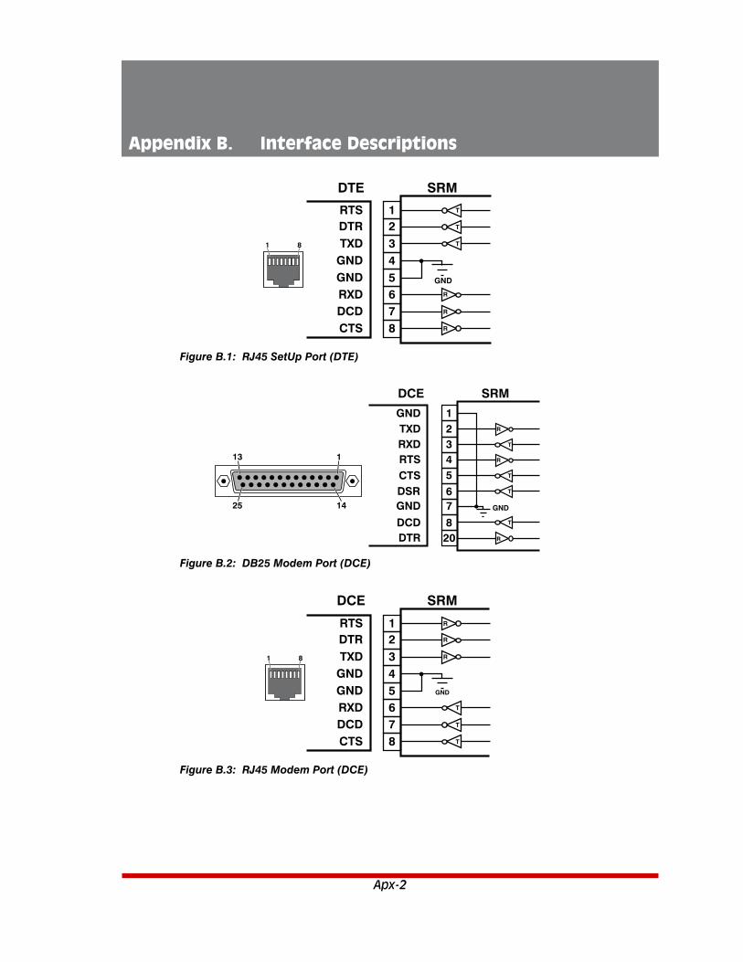
Apx-2
Appendix B. Interface Descriptions
1 8
12345678
RTSDTRTXD
RXDDCDCTS
GNDGND
R
R
R
T
T
T
GND
DTE SRM
1
2TXD
DCE SRM
RXDRTSCTSDSRGND
DCDDTR
GND
34567
820
1
13
25 14
R
T
T
T
T
GND
R
R
1 8
12345678
RTSDTRTXD
RXDDCDCTS
GNDGND
R
R
R
T
T
T
GND
DCE SRM
FigureB.1:RJ45SetUpPort(DTE)
FigureB.2:DB25ModemPort(DCE)
FigureB.3:RJ45ModemPort(DCE)

Apx-3
Appendices
1 6
123456
Not UsedNot UsedRING
Not Used
TIPNot Used
FigureB.4:RJ11PhoneLinePort

Apx-4
Appendix C. Customer Service
Customer Service hours are from 8:00 AM to 5:00 PM, PST, Monday through Friday. When calling, please be prepared to give the name and make of the unit, its serial number and a description of its symptoms. If the unit should need to be returned for factory repair it must be accompanied by a Return Authorization number from Customer Service.
WTI Customer Service 5 Sterling
Irvine, California 92618
Local Phone: (949) 586-9950 Toll Free Service Line: 1-888-280-7227
Service Fax: (949) 583-9514
Email: [email protected]

Apx-5
Appendices
Trademark and Copyright Information
WTI and Western Telematic are trademarks of Western Telematic Inc.. All other product names mentioned in this publication are trademarks or registered trademarks of their respective companies.
Information and descriptions contained herein are the property of Western Telematic Inc.. Such information and descriptions may not be copied, disseminated, or distributed without the express written consent of Western Telematic Inc..
© Copyright Western Telematic Inc., 2015.
November, 2015Part Number: 14439, Revision: A
TrademarksandCopyrightsUsedinthisManual
Hyperterminal is a registered trademark of the Microsoft Corporation. Portions copyright Hilgraeve, Inc.
Teraterm is a copyright of Ayera Technologies, Inc.
BlackBerry is a registered trademark of Research In Motion Limited.
JavaScript is a trademark of Sun Microsystems, Inc.
Telnet is a trademark of Telnet Communications, Inc.
Thawte is a trademark of Thawte, Inc.
VeriSign is a registered trademark of VeriSign, Incorporated
All other trademarks mentioned in this manual are acknowledged to be the property of the trademark owners.