secure sensor networks for perimeter protectionsavanc1/papers/sensor_security.pdf · secure sensor...
TRANSCRIPT
Computer Networks 43 (2003) 421–435
www.elsevier.com/locate/comnet
Secure sensor networks for perimeter protection
Sasikanth Avancha *, Jeffrey Undercoffer, Anupam Joshi, John Pinkston
Department of Computer Science and Electrical Engineering, University of Maryland, Baltimore County, 1000 Hilltop Circle,
Baltimore, MD 21250, USA
Abstract
Sensor networks have been identified as being useful in a variety of domains to include the battlefield and perimeter
defense. We motivate the security problems that sensor networks face by developing a scenario representative of a large
application class where these networks would be used in the future. We identify threats to this application class and
propose a new lightweight security model that operates in the base station mode of sensor communication, where the
security model is mindful of the resource constraints of sensor networks. Our application class requires mitigation
against traffic analysis, hence we do not use any routing mechanisms, relying solely on broadcasts of end-to-end en-
crypted packets. Our model extends the broadcast range of the base station model by utilizing nodes adjacent to the
base station as an intermediary hop. Additionally, our model detects and corrects some classes of aberrant node be-
havior. We have simulated our model and present simulation results.
� 2003 Elsevier B.V. All rights reserved.
Keywords: Wireless sensor network; Energy-efficient security; Authentication; Confidentiality; Perimeter protection
1. Introduction
Improvements in wireless networking andmicro-electro-mechanical systems (MEMS) are
contributing to the formation of a new computing
domain––distributed sensor networks. These ad-
hoc networks of small, fully programmable sensors
will be used in a variety of applications: on the bat-
tlefield, as medical devices, in equipment mainte-
nance and in perimeter security systems [1,2].
These distributed sensor networks are character-
* Corresponding author. Tel.: +1-410-455-2668; fax: +1-410-
455-3969.
E-mail addresses: [email protected] (S. Avancha),
[email protected] (J. Undercoffer), [email protected]
(A. Joshi), [email protected] (J. Pinkston).
1389-1286/$ - see front matter � 2003 Elsevier B.V. All rights reserv
doi:10.1016/S1389-1286(03)00352-9
ized by limited power supplies, low bandwidth,
small memory sizes and a different traffic model.
Whereas the traffic model of mobile ad-hoc net-works is typically many-to-many, the traffic model
of a sensor network is more of a hierarchical
model and/or many to one. Generally, MEMS are
significantly more resource constrained than typi-
cal ‘‘mobile’’ or ‘‘handheld’’ devices. A node in a
sensor network may or may not have computing
requirements. In the case where computations are
required, if the cost of a communication is lessthan the cost of the computation, the computation
may be replaced by a request to a computationally
robust central location. The threat to a sensor
network is different from the threat to a mobile ad-
hoc network. As such, existing network security
mechanisms, including those developed for Mobile
Ad-Hoc Networks, are a poor fit for this domain.
ed.

422 S. Avancha et al. / Computer Networks 43 (2003) 421–435
Research into authentication and confidentiality
mechanisms designed specifically for sensor data
and network control protocols is needed. Given
the fact that little prior work ([3] being the ex-
ception) exists in this space, there is a need both to
identify the problems and challenges and proposesolution techniques.
In this paper, we motivate the security problems
that sensor networks face by developing a scenario
representative of a large application class where
such networks would be used in the (near) future.
The specific application that we consider in this
work is perimeter protection for high government
officials. We identify the threats and vulnerabilitiesto this application, starting from the radio layer
and progressing to the application layer. This
paper details why security mechanisms that are
presently used in mobile ad-hoc environments are
inadequate or not appropriate for sensor networks
designed for this application. We then describe a
new security model that serves as a countermea-
sure to the identified threats. Our model of sensornetwork utilizes the central, fixed base station
paradigm and is mindful of the resource con-
straints of sensor networks. We have implemented
our model in SensorSim [4] and present our sim-
ulation results.
The remainder of this paper is organized as
follows. Section 2 details related research in the
area of security for sensor networks. Section 3details our class of application, stating how sensor
networks are a solution. Section 4 details our se-
curity protocol for sensor networks designed for
this application class. Section 5 details our imple-
mentation and simulation results. We state our
plans for future work in Section 6.
2. Related work
There is relatively little work in the area of se-
curing sensor networks. Like their mobile ad-hoc
counterparts, sensor networks lack a fixed infra-
structure and the topology is dynamically de-
ployed. Addressing the security of mobile ad-hoc
networks, Yi et al. [5] point out that if the routingprotocol can be subverted and messages altered in
transit, then no amount of security on the data
packets can mitigate a security threat at the
application layer. Consequently, they introduce
‘‘Security Aware Ad-hoc Routing’’ (SAR). SAR
characterizes and explicitly represents the trust
values and relationships associated with ad-hoc
nodes and uses these values to make secure routingdecisions. They address two problems: Ensuring
that data is routed through a secure route com-
posed of trusted nodes and the security of the in-
formation in the routing protocol. To motivate
their scenario, they use the example of two military
generals wishing to communicate via an ad-hoc
network using a generic form of the Ad-Hoc On
Demand Distance Vector Routing (AODV) proto-col. They employ a route discovery protocol where
only nodes with a security metric equivalent to the
sender and receiver participate in the routing
process. Their work appears to be based on the
Bell-La Padula Confidentiality Model [6]. Their
model, however, is dependent on self-enforcement
where nodes with a lower than required security
level voluntarily opt out of participating in thehop-by-hop routing process.
Perrig et al. [3] introduce ‘‘SPINS: Security
Protocols for Sensor Networks’’ comprised of
Sensor Network Encryption Protocol (SNEP) and
lTESLA. The function of SNEP is to provide
confidentiality (privacy), two-party data authenti-
cation, integrity and freshness. lTESLA is to
provide authentication to data broadcasts. SPINSpresents an architecture where the base station
accesses nodes using source routing. We describe
SPINS in greater detail in Section 4.5 and also
compare it to our model.
3. Perimeter protection as a class of sensor appli-
cations
We motivate our application class of perimeter
security by considering the following scenario.
In today�s geopolitical climate the threat posed
to high-level government officials is overwhelming,
particularly when they are engaged in official
business and traveling outside of their home
countries.Consider the typical case of a country�s foreign
minister. She travels extensively, often on the spur
S. Avancha et al. / Computer Networks 43 (2003) 421–435 423
of the moment, and sometimes to destinations that
are hostile. Due to the nature of her office, her
security detail may not have had adequate time to
conduct a detailed advance and install the requisite
security controls.
The foreign minister faces a number of threats.Physical threats include poisoning from radiation,
chemical or biological toxins. These are in addition
to threats from explosives and individuals utilizing
small arms or other military ordnance. More in-
sidious threats are posed by collection efforts
aimed at both the substance of her agenda and at
analyzing security controls in order to compromise
them at some later time.Such perimeter security applications represent a
vast class of ‘‘monitoring and responding’’ type
applications for which sensor networks will be
used. We believe that a solution designed to miti-
gate the aforementioned threats will also cover the
broad spectrum of all threat models that such
applications face.
Our application, and its attendant securitymodel, may be abstracted and applied to other
scenarios where concentric circles of perimeter
protection need to be temporarily established.
Examples of other applications are placing alarm
fields on a border and at ports of entry in order to
prevent the smuggling of hazardous materials and
munitions and to prevent illegal entry. For exam-
ple, suppose information is developed leading tothe suspicion that some person or persons un-
known will be attempting to move fissionable
material across a remote section of a country�sborder. Furthermore, suppose that this material
produces a signature which is only discernible at
distances of 20 m or less. Such a scenario is within
the realm of possibility. Moreover, it is conceiv-
able that those behind such an operation could beleaking spurious information so as to cause the
authorities to take precautionary measures, only
to study, analyze and circumvent future preventive
measures. This is in effect a ‘‘dry run’’ in prepa-
ration for the actual event. A sensor network could
be rapidly deployed in order to prevent and ap-
prehend those involved in such an event. However,
the underlying architecture of the sensor networkmust be able to withstand probes and analyses in
order to remain effective over time.
3.1. Sensor technology as a solution
Sensors are still some time away from actual
mass fabrication and use. Current smartsensor
prototypes, such as the Berkeley Renee Mote,have a larger footprint and are generally restricted
to the following sensor types: accelerometers,
microphones, light, motion and magnetometers.
We envision a design inclusive of these sensors
types; however, our proposed application assumes
a (not so) futuristic scenario that include sensors
that test for nitrates (explosives), chemical toxins,
biological toxins and radiation. For example,sensors testing for motion and sound would be
placed on rooftops, which provide an assailant(s)
with a vantage point. Sensors testing for radiation
would be placed in areas frequented by the pro-
tectee, while sensors testing for chemical and bio-
logical toxins would be placed in airways that feed
into areas frequented by the protectee. Our col-
leagues at UMBC in the Department of Chemi-cal and Biochemical Engineering are deploying
such sensors [7], and we feel that such sensors
will eventually be integrated with sensor proto-
types.
Our contribution in this area is the creation of
lightweight techniques for securing existing sensor
network routing and data movement approaches,
such as directed diffusion [8], SPIN [9] and datadissemination [10,11]. We assume the computa-
tional capability and memory requirements typical
of those provided by sensors designed for the ap-
plications described above. We further assume that
the base station is fixed, always attended and is in
a secure location. We note, that in this work we
make no attempt to counter the threat from a
widespread denial of service attack against the RFlayer. As pointed out in [12], such attacks are fairly
straightforward to mount against fixed frequency
RF communication links that are found in the
sensors. Defending against them requires changes
to the RF layer of the sensor, such as the use of
spread spectrum techniques, which can mitigate
against an RF level DoS attack. In our scenario,
and many others, a denial of service is in itself analarm.
The typical security problems that we might
expect in the above scenario include:

424 S. Avancha et al. / Computer Networks 43 (2003) 421–435
ii(i) Passive Information Gathering: If communi-
cations between sensors, or between sensors
and base stations, are in the clear, then an
intruder with an appropriately powerful re-
ceiver and well designed antenna can easilypick off the data stream. If information has
to be encrypted, then ‘‘how’’ is the open ques-
tion. In other words, which cryptographic ap-
proaches will be best, given the resource
constraints and the routing paradigm em-
ployed by the sensor?
i(ii) Subversion of a Node: A particular sensor
might be ‘‘captured’’, and information storedon it (such as the key) might be obtained by
an adversary. If a node has been compro-
mised, then how to exclude that node, and
that node only, from the sensor network is
at issue. A number of vendors of crypto-
graphic modules, such as smart cards, that
store keying material are compliant with
FIPS-140-2 [12], which may be adapted tothe security solutions for sensor networks.
(iii) False Node: An intruder might ‘‘add’’ a node
to the system that feeds false data or prevents
the passage of true data. While such problems
with malicious hosts have been studied in dis-
tributed systems, as well as ad-hoc network-
ing, the solutions proposed there (group key
agreements, quorums and per hop authentica-tion) are in general too computationally de-
manding to work for sensors.
(iv) Legitimate Addition of a Node to an Existing
Sensor Network: If a node needed to be re-
placed or another node needed to be added
to an existing sensor network, securely inte-
grating the new node into the existing network
is at issue.
3.2. Assumptions
We make the following assumptions when ap-
plying sensor technology as a solution to our ap-
plication class of perimeter security:
• The base station is computationally robust, hav-ing the requisite processor speed, memory and
power to support the cryptographic and routing
requirements of the sensor network. As stated
above, the base station is in a fixed, secure lo-
cation and is always attended. Hence, it is con-
sidered to be within a trusted computing
environment. The assumptions of secure loca-
tion and constant attendance are not valid forthe individual sensor nodes.
• Key management and re-keying mechanisms
are not necessary because the base station,
which holds the cryptographic keys of all sensor
nodes, is secure.
• The communication paradigm is one-to-one,
not one-to-many or many-to-one. Even though
all messages are broadcast at the routing andMAC levels, each message has an intended re-
cipient. The threat of traffic analysis is mitigated
by the use of end-to-end encryption of all trans-
missions.
• The physical security protocol of our applica-
tion class follows the traditional model of con-
centric circles of protection, where the inner
circle is resource rich. Conversely, as the dis-tance from the inner circle increases the controls
and mechanism become more general and are
deployed in fewer numbers.
4. Security model
Security is a broadly used term encompass-ing the characteristics of authentication, integrity,
confidentiality, non-repudiation and anti-play-
back. In the case of our sensor network the secu-
rity requirements are comprised of authentication,
integrity, confidentiality, anti-playback and resil-
ience against traffic analysis. The recipient of a
message needs to be able to be unequivocally as-
sured that the message came from its stated source.Similarly, the recipient needs to be assured that the
message was not altered in transit and that it is not
an earlier message being replayed in order to veil
the current environment. Finally, all communica-
tions need to be kept secret so that eavesdroppers
cannot intercept, study and analyze, and devise
counter measures in order to circumvent the pur-
poses of the sensor network.Our approach to defining a security model for
sensor networks is resource driven and factors in
the trade offs between levels of security and the

BS
Fig. 1. Example network topology.
Preamble Header Payload
< Addr_1( ), EKey j {Addr_2( j), DTG , COMMAND}, E Key j {data}>
(a)
Preamble Header Payload
(Addr_1( j ), EKey j {Addr_2( j ), DTG , COMMAND} ) , E Key j {data}>< EKey BS
(b)
Fig. 2. (a) Base station to sensor message format; (b) sensor to
base station message format.
S. Avancha et al. / Computer Networks 43 (2003) 421–435 425
requisite power and computational resources.
Primarily, we envision a scenario where a pro-
tected perimeter based on sensors is dynamically
deployed. However, similar scenarios could be
envisioned in an environment where the topology
is well known in advance and the sensor network ispre-configured. Our operating paradigm is where
data is reported to a computationally robust cen-
tral location such as a base station or network
controller.
4.1. Single collection and authentication point (base
station) paradigm
Consider the family of sensor routing protocols
where each sensor communicates either directly or
indirectly with a base station. In turn, the base
station correlates and aggregates information from
each sensor. Accordingly, the base station will
need to verify the authenticity of the sensor, the
integrity of the communication and ascertain that
it is not a replay of an earlier communication.Recall the assumption that the base station is
computationally robust and secure. In our proto-
col each sensor j shares a unique 64-bit key Keyjand a 64-bit common key KeyBS, with the base
station. Our protocol provides for a two-hop sce-
nario where the range of a base station is extended,
employing nodes that are adjacent to the base
station to serve as intermediaries for non-adjacentnodes. Fig. 1 depicts an example of such a sensor
network topology.
Our goal is to provide confidentiality and in-
tegrity to the data, to authenticate the sender, to
prevent replay attacks and to prevent traffic anal-
ysis; consequently, the entire communication is
encrypted end-to-end. All communications consist
of a preamble, header and payload. The preambleis empty if the communication originates from the
base station and is directed to a sensor, otherwise
it contains the address of the sending node. The
header contains the recipient�s address, nonce and
a command and is encrypted under key Keyj,which is shared between the base station and node
j. The payload contains data exchanged between
the node and the base station. As will be explained,the payload is encrypted under the shared key of the
destination node, which may be different from the
key used to encrypt the header. This differencecomes into play when the communication needs to
be relayed by an intermediate node. Fig. 2 depicts
the communication format.
Where
• Addr_1 is empty if the communication is from
the base station to a sensor.
• Addr_1 contains the address of the transmittingnode if the communication is directed to the
base station. A non-empty Addr_1 field enables
the base station to immediately select the cor-
rect key, instead of trying keys until it locates
the correct one.
• Addr_2 contains the address of the destination
node if the communication is from the base

426 S. Avancha et al. / Computer Networks 43 (2003) 421–435
station to a node. If the communication is from
a node to the base station Addr_2 will contain
the address of the sending node.
• DTG is the date-time-group and is a nonce used
to prevent replay attacks.• COMMAND describes the contents of the mes-
sage to the recipient.
Accordingly, a communication from the base sta-
tion to a node j is of the form depicted in Fig. 2(a),
and a communication from a node j to the
base station is of the form: EKeyBS(Preamble,
EKeyj(Header)), EKeyj(Payload). On receipt, thebase station decrypts the communication, uses the
address contained in the preamble to select the key
shared with the node and decrypts the message.
The use of double encryption prevents the dis-
closure of the number of nodes in the network and
their addresses, consequently preventing traffic
analysis. Should a single node be compromised
and the its keys disclosed, the network will be ableto function albeit the unique addresses of each
node will be disclosed.
4.2. Topology discovery and network setup
The base station is deployed with the unique
ID, symmetric encryption key of each node in the
sensor network and a master key, KeyBS. Similarly,each node is deployed with the unique key, Keyjthat it shares with the base station and KeyBS. As
in SPINS, its clock is synchronized with the base
station�s clock. We note that sensors do not obtain
their keys ‘‘over the air’’ from the base station;
rather every sensor is programmed with a unique
key. Upon initialization of the sensor network the
base station learns the network topology, createsand optimizes a routing table and provides a
mechanism to non-adjacent (out of radio range)
nodes that enables them to securely communicate
with the base station.
At start up, the base station sends a HELLO
message to each node j. A node j attempts to de-
crypt the header of this message using its key.
Successful decryption implies that the message wasintended for j. Node j responds to the HELLO
message with a HELLO-REPLY message that it
constructs using the message format in Fig. 2(b).
On receiving the encrypted HELLO-REPLY
message, the base station decrypts the preamble
using KeyBS. It obtains j�s address from Addr_2,
uses it to determine Keyj from its Key Table and
decrypts the header. If the header contains a valid
DTG and the HELLO-REPLY command, then jis adjacent to the base station and the latter adds
that node to its route table. Those nodes that did
not reply are assumed to be two hops away and
non-adjacent to the base station.
For these non-adjacent nodes k, the base sta-
tion sends a HELLO message via each adjacent
node j. In order to accomplish this, the base sta-
tion places the header and payload of this messagein the payload of a message containing the RE-
LAY command and directs the RELAYmessage to
a particular adjacent node j. In a RELAY message,
the header is encrypted under Keyj and the pay-
load, intended for k, is encrypted under Keyk.On receipt of the RELAY message, node j
prepends the original preamble to the payload and
transmits the new message. The header of themessage received by k contains a HELLO com-
mand and the payload contains a mechanism that
will be used by k to reach the base station through
the intermediate (adjacent) node j.This mechanism, referred to as W, is a header
containing the RELAY command encrypted under
Keyj. To respond to the HELLO message, k con-
structs a HELLO-REPLY message encrypting itunder Keyk and places it in the payload. The pre-
amble containing Addr_2(k) and W are prepended
to the payload and the message is transmitted. In
turn, the adjacent node j receives the transmission,
decrypts the header and upon seeing the RELAY
command, prepends the preamble, appends
EKeyBSðjÞ to the payload and transmits it to the
base station. Once the base station discovers whichnodes are adjacent to it and all of the paths by
which the non-adjacent nodes are reachable, it
optimizes its route table so as to not overburden
an adjacent node with the task of relaying mes-
sages. If the optimization process results in a dif-
ferent route, the base station sends the affected
non-adjacent node an updated W.
Fig. 3 shows the format of the HELLO andHELLO-REPLY message types exchanged be-
tween the base station and adjacent nodes. Fig. 4

HELLO: Preamble; EKeyj{Header}; PayloadPreamble: Addr_1()Header: Addr2_(j), DTG, HELLOPayload: ϕ
HELLO-REPLY: EKeyBS{Preamble, Header}; PayloadPreamble: Addr_2(j)Header: EKeyj{Addr_2(j), DTG, HELLO-REPLY}Payload: ϕ
Fig. 3. Messages exchanged between base station and adjacent
nodes.
RELAY-HELLO: Preamble; EKeyj{Header} (=ψ); EKeyk{Payload}Preamble: Addr_1()Header: Addr2_(j), ϕ, RELAYPayload: [Addr2_(k), DTG, HELLO], ψ
HELLO-RELAYED: Preamble; Header; PayloadPreamble: Addr_1()Header: EKeyk{Addr2_(k), DTG, HELLO}Payload: ψ
RELAY-HELLO-REPLY: EKeyBS{Preamble, Header}; PayloadPreamble: Addr_2(k)Header: ψPayload: EKeyk{Addr_2(k), DTG, HELLO-REPLY}
HELLO-REPLY-RELAYED: EKeyBS{Preamble, Header}; PayloadPreamble: Addr_2(k)Header: EKeyk{Addr_2(k), DTG, HELLO-REPLY}Payload: EKeyBS{j}
Fig. 4. Messages exchanged between base station and non-
adjacent nodes.
Fig. 5. Secure topology discovery and network setup protocol.
S. Avancha et al. / Computer Networks 43 (2003) 421–435 427
shows the formats of these two message types
exchanged between the base station and a non-
adjacent node via an adjacent node. The secure
topology discovery and network setup algorithm is
presented in Fig. 5.Three tables are maintained by the base station
to help maintain and repair the network as re-
quired.
The Route Table contains the primary route,
indicated by an *, and alternate routes to a node.
An entry of the form A:( ) indicates that the node
is directly connected to the base station whereas an
entry such as D:(A) indicates that A is an inter-mediate node between the base station and node
D.
The Key Table contains the unique key shared
by node j and the base station.
The Activity Table contains the most recent
Date Time Group (DTG) received by the base
station from a particular node, a count (X ) of
corrupted messages sent by the node, and a count
(Y ) of other nodes dependent upon this node to
relay messages. The values of X and Y are used to
detect aberrant behavior on the part of an indi-
vidual node.
These tables and other symbols used in the
network setup and topology discovery and thenetwork repair protocol are illustrated in Fig. 6.
We use DES [13] with a 64-bit key in Cipher
Feedback (CFB) mode [14] (also known as cipher
text auto-key) for data encryption. This type of
cryptosystem is also detailed in [15,16]. We se-
lected DES because it is a well-known and stan-
dardized encryption algorithm. It is resilient to
cryptanalysis and its only known vulnerability is toa brute-force attack. However, to effectively im-
plement a brute-force attack, some degree of
knowledge about the expected plaintext is required
in order to distinguish between plaintext and gar-
ble. Additionally, [17] has shown that DES can be
optimized to reduce power consumption by 66%.
For the application class of perimeter protection,
the encryption algorithm need only withstand abrute-force attack for the life of the sensor net-
work, which we expect to be of the order of weeks.

Fig. 6. Detailed example network topology.
428 S. Avancha et al. / Computer Networks 43 (2003) 421–435
To prevent traffic analysis, the entire commu-
nication is encrypted. Accordingly, a node will
need to decrypt all communications that it
‘‘hears’’. This adds very little overhead because
when the node decrypts the first 64 bits of themessage, the recipient�s address (Addr_2) is re-
vealed. If a valid address is present then the node
will continue to decrypt the message, otherwise it
will discard it.
As previously stated, authentication is achieved
through the use of a shared secret, which is the 64-
bit key Keyj, shared between the base station and
node j. Message integrity is achieved through theselection of an encryption algorithm that exhibits
strong properties of diffusion and confusion. Ac-
cordingly, an attack aimed at altering the message
will only be against the form of the message and not
its substance. Anti-playback is achieved by the use
the Date-Time-Group. Finally, privacy is achieved
as a result of encrypting all communications.
4.3. Inserting additional nodes into the network
The insertion of an additional node into the
existing sensor network is easily accomplished. In
our model the unique identity and the key Keym of
some node m to be added are loaded into the base
station, the new node�s clock is synchronized with
that of the existing network and the base station
repeats the topology discovery algorithm, explic-
itly looking for the new node. Once the new node
is discovered, the routing table is re-optimized. Forthe perimeter protection application class, the need
to insert additional nodes into the network is not
expected to be high, given the limited duration for
which protection is required.
4.4. Isolating aberrant nodes
Anaberrant node is one that is not functioning asspecified. Identifying and isolating aberrant nodes
that are serving as intermediate nodes is important
to the continued operation of the sensor network.
A node may cease to function as expected for
several reasons, to include:
1. It has exhausted its source of power.
2. It was damaged.3. It is dependent upon an intermediate node and
is being blocked because the intermediate node
has fallen victim to 1 and 2 above.
4. It is dependent upon an intermediate node and
is being deliberately blocked because the inter-
mediate node has been compromised.

S. Avancha et al. / Computer Networks 43 (2003) 421–435 429
5. An intermediate node has been compromised
and it is corrupting the communication by mod-
ifying data before forwarding it.
Our protocol effectively mitigates against the classof attack/failure where an intermediate node is
involved. The protocol for the detection of aber-
rant nodes is presented in Fig. 7.
Periodically, the base station checks the activity
table associated with a node, testing for a pro-
longed period of inactivity, D. If the node is di-
rectly connected (i.e., it does not rely upon an
intermediate node) this could be evidence of ab-
Fig. 7. Network repair protocol.
errant behavior on the part of the node. If the
node relies upon an intermediate node this could
be evidence of aberrant behavior on either the part
of the node or the intermediate node. In either
case, the base station POLLs the node.
In the case of an adjacent node, if the basestation does not receive a POLL-REPLY within a
specified time out period t, it increments its coun-
ter of route failures (ActivityY ) for that node.
In the case of a non-adjacent node, the base
station first polls the primary intermediate node. If
it receives a POLL-REPLY, it polls the node via
the primary. Receipt of a POLL-REPLY indicates
that everything is in order. The non-receipt of aPOLL-REPLY causes the base station to POLL
the node via an alternate path, if it exists. A re-
sponse from the non-adjacent node via the alter-
nate path prompts the base station to transmit an
UPDATE-PSI to it and increment ActivityY for
the primary. A non-response causes the base sta-
tion to delete the non-adjacent node from its route
table.If the base station did not receive a POLL-
REPLY from the primary intermediate node, it
POLLs the non-adjacent node via an alternate
path, if it exists. Upon receipt of a POLL-REPLY,
it transmits an UPDATE-PSI message, which re-
flects the alternate route, to the non-adjacent node
and increments ActivityY for the primary. If it
does not receive a POLL-REPLY from the non-adjacent node via the alternate path, it deletes that
node from its route table.
The base station also checks for a high inci-
dence of corrupted messages originating from a
non-adjacent node. An intermediate node that has
become aberrant may corrupt data that it is re-
laying on behalf of a non-adjacent node. This be-
havior constitutes a denial-of-service (DoS) attack.In order to mitigate against such an intermediate
node, the base station keeps a counter of corrupted
packets, ActivityX . When this counter crosses a
pre-determined threshold, the base station trans-
mits an UPDATE-PSI to all non-adjacent nodes
affected by the intermediate node via alternate
paths, if they exist, and deletes the aberrant in-
termediate node from its route table. A non-adja-cent node may be sending corrupt data which the
intermediate faithfully relays. The base station

430 S. Avancha et al. / Computer Networks 43 (2003) 421–435
tests for this situation by transmitting a POLL to
the non-adjacent node via an alternate path, if it
exists. Non-receipt of a POLL-REPLY from the
non-adjacent node causes it to be deleted from the
base station�s route table; receipt indicates that
everything is in order.
4.5. Comparison with SPINS
SPINS is comprised of Sensor Network En-
cryption Protocol (SNEP) and Micro Timed
Efficient Stream Loss-tolerant Authentication
(lTESLA). The function of SNEP is to provide
confidentiality (privacy), two-party data authenti-cation, integrity and freshness. lTESLA is to
provide authentication to data broadcasts. We
compare our security model to SNEP in terms of
functionality. We do not compare it to lTESLAbecause we do not perform broadcast authentica-
tion.
In SNEP each node j shares a unique master
key Kj with the base station. This master key isused to derive all other keys. For data encryp-
tion SNEP employs a one time encryption key
produced by using a key derived from Kj and an
incremental counter (message indicator) as inputs
to the RC5 cryptographic algorithm. The RC5
algorithm outputs a binary string that is used as
the one time key. The message is XORed with
the one time key, transmitted and the counter isincremented in preparation for the next mes-
sage. The base station, aware of the node�scounter value and the derived key, produces
the identical one time key, XORs the encrypted
message with the one time key to produce the
clear text.
Our protocol differs from SPINS in the fol-
lowing fundamental and essential ways:
1. SPINS uses source routing, which like all non-
broadcast routing mechanisms, is vulnerable
to traffic analysis. Our protocol relies upon
broadcasts where the entire communication is
end-to-end encrypted in order to mitigate
against the threat posed by traffic analysis.
2. We provide a mechanism for detecting certaintypes of aberrant behavior, behavior that may
be due to either a compromise or malfunction
of an individual node. In either case we are able
to remove the node from the network. This is
extremely important in the case of applications
such as perimeter protection, because the longer
a compromised node remains in the network,the greater its chances of being able to break
down the perimeter.
3. SPINS has been highly optimized in order to re-
duce code footprint on the SmartDust Mote.
Although, our model has not been optimized
for a specific sensor platform, the encryption al-
gorithm may be replaced to better suit different
hardware platforms.
In addition, we note that our protocol differs from
SPINS in terms of the application class. Our pro-
tocol is designed to function correctly in sensor
networks used for perimeter protection.
5. Implementation details and simulation results
We have implemented the topology discovery
and network setup components of our protocol
using the SensorSim [4] extension of the NS net-
work simulator [18]. The entire protocol, to in-
clude cryptographic functionality is implemented
at the routing layer. We generated 100 crypto-
graphic keys, where the first key was used as theKeyBS. These keys were placed in the base station.
Individual keys and KeyBS were also placed in
each node. Topology distribution files, consisting
of the ðx; yÞ co-ordinates of each node were cre-
ated for four different distributions, which we
explain shortly. Each distribution file and a con-
figuration file were used as inputs to the simula-
tor. The correctness of the topology discoveryand network setup protocol was verified by ob-
serving the successful encryption, transmission,
reception, decryption and response to each mes-
sage. Additionally, the routing table created by
the base station was visually inspected to verify
that each adjacent node was associated with ap-
proximately the same number of non-adjacent
nodes. The correctness of the network repairprotocol was verified by observing the base sta-
tion�s response to node failures and corrupted
data.

S. Avancha et al. / Computer Networks 43 (2003) 421–435 431
5.1. Simulation
We used the simple battery, radio and CPU
models of the simulator. According to the battery
model, the initial energy of the battery attached toeach sensor node is 36 A s (10 mAh). According to
the radio model, message transmission and recep-
tion at a data rate of 19.2 Kbps draw 5.2 and 4.1
mA of current, respectively. The model assumes a
radio range of 15 m. The CPU model assumes that
the CPU draws 2.9 mA in active mode and 1.9 mA
in sleep mode. For purposes of this simulation, we
assume a voltage of 1 V. It should be noted thatthe CPU is assumed to draw a constant amount of
current in active mode, irrespective of the task it
performs, be it a simple arithmetic function or
encryption of a message. We assume a message
length of either 24 or 48 bytes.
We conducted experiments to measure energy
expenditure of each sensor function (Tx, Rx and
CPU) during network setup time for four differentnetwork topologies. We simulated a geographic
environment measuring 5654 m2. We divided this
environment into two concentric circles, the inner
circle with a radius of 15 m and the outer circle
with a radius of 30 m. The base station was located
at the center. The sensor placement within our
experimental topologies is as follows:
1. 30 nodes randomly placed in the inner circle
and 70 nodes randomly placed in the outer
circle;
2. 50 nodes randomly placed in the inner circle
and 50 nodes randomly placed in the outer
circle;
3. 70 nodes randomly placed in the inner circle
and 30 nodes randomly placed in the outercircle;
4. 100 nodes randomly placed across the entire
area.
The results of our experiments are illustrated in the
graphs contained in Fig. 8. We measured the en-
ergy consumed (Y axis) by each component of the
sensor: the transmitter, receiver and CPU, for theentire network of 1 base station and 99 sensors,
plotting it against the time taken (X axis) for the
particular network topology to converge. We used
a log plot so that small values would be discern-
ible.
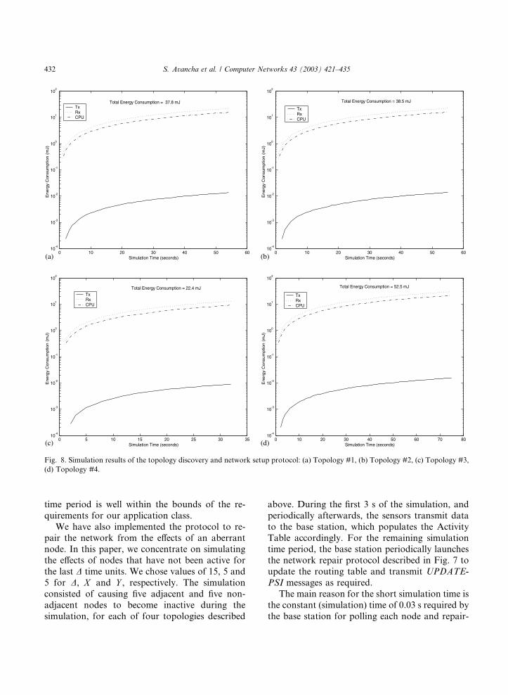
Accordingly, Fig. 8(a) shows the results for
Topology #1. Topology discovery and network
setup occurred in 54 s of simulation time with atotal energy expenditure of 37.8 mJ for all nodes in
the sensor network. Fig. 8(b) shows the results for
Topology #2. It took 55 s of simulation time for
topology discovery and network setup and the
total network energy consumption was 38.5 mJ.
The energy expenditure and time taken for To-
pology #3 is illustrated in Fig. 8(c). Here energy
consumption was 22.4 mJ and it took 32 s. Therandom distribution of sensors in Topology #4
took 75 s of simulation time and energy con-
sumption was 52.5 mJ.
In all cases, and as anticipated, the receiver
(Rx) component consumed the highest amount
energy, closely followed by the CPU. The trans-
mitter (Tx) component consumed the least amount
of energy. This is intuitive, as the number ofmessages received greatly outweighs those trans-
mitted.
The topology with the densest inner circle and
the sparsest outer circle consumed the least
amount of energy and converged the quickest. The
topology scenario that was most representative of
the methods used for physical protection (30 inner
nodes and 70 outer nodes) was near the median fortime and energy consumption. Our results indicate
that as the ratio of adjacent to non-adjacent nodes
increases in favor of adjacent nodes, energy con-
sumption for topology discovery and network
setup decreases.
The cost of network setup, in terms of energy
consumption, is the most expensive period due to
the volume of messages. However, energy con-sumption decreases from this point forward for the
life of the sensor network. To put the energy re-
quirements into perspective, suppose that a sensor
network using our security protocol were to
maintain its peak rate for a protracted period. If
this were the case then each sensor equipped with a
battery similar to the Eveready X91 with a ca-
pacity of 3135 mAh would sustain it for approx-imately 435 h. (Note: the Berkeley Renee Mote
uses two of these batteries [19].) As our network
would have a required lifespan of a few days, this
0 10 20 30 40 50 6010
-4
10-3
10-2
10-1
100
101
102
Simulation Time (seconds)
Energ
y C
onsu
mptio
n (
mJ)
TxRxCPU
Total Energy Consumption = 37.8 mJ
0 10 20 30 40 50 6010
-4
10-3
10-2
10-1
100
101
102
Simulation Time (seconds)E
nerg
y C
onsu
mptio
n (
mJ)
TxRxCPU
Total Energy Consumption = 38.5 mJ
0 5 10 15 20 25 30 3510
-4
10-3
10-2
10-1
100
101
102
Simulation Time (seconds)
Energ
y C
onsu
mptio
n (
mJ)
TxRxCPU
Total Energy Consumption = 22.4 mJ
0 10 20 30 40 50 60 70 8010
-4
10-3
10-2
10-1
100
101
102
Simulation Time (seconds)
Energ
y C
onsu
mptio
n (
mJ)
TxRxCPU
Total Energy Consumption = 52.5 mJ
(a) (b)
(d)(c)
Fig. 8. Simulation results of the topology discovery and network setup protocol: (a) Topology #1, (b) Topology #2, (c) Topology #3,
(d) Topology #4.
432 S. Avancha et al. / Computer Networks 43 (2003) 421–435
time period is well within the bounds of the re-
quirements for our application class.
We have also implemented the protocol to re-
pair the network from the effects of an aberrantnode. In this paper, we concentrate on simulating
the effects of nodes that have not been active for
the last D time units. We chose values of 15, 5 and
5 for D, X and Y , respectively. The simulation
consisted of causing five adjacent and five non-
adjacent nodes to become inactive during the
simulation, for each of four topologies described
above. During the first 3 s of the simulation, and
periodically afterwards, the sensors transmit data
to the base station, which populates the Activity
Table accordingly. For the remaining simulationtime period, the base station periodically launches
the network repair protocol described in Fig. 7 to
update the routing table and transmit UPDATE-
PSI messages as required.
The main reason for the short simulation time is
the constant (simulation) time of 0.03 s required by
the base station for polling each node and repair-

0 2 4 6 8 10 12 14 16 18 2010
-4
10-3
10-2
10-1
100
101
Simulation Time (seconds)
En
erg
y C
on
sum
ptio
n (
mJ)
TxRxCPU
Total Energy Consumption = 13.3 mJ
0 2 4 6 8 10 12 14 16 18 2010
-4
10-3
10-2
10-1
100
101
Simulation Time (seconds)E
ne
rgy
Co
nsu
mp
tion
(m
J)
TxRxCPU
Total Energy Consumption = 13.3 mJ
0 2 4 6 8 10 12 14 16 18 2010
-4
10-3
10-2
10-1
100
101
Simulation Time (seconds)
En
erg
y C
on
sum
ptio
n (
mJ)
TxRxCPU
Total Energy Consumption = 13.3 mJ
0 2 4 6 8 10 12 14 16 18 2010
-4
10-3
10-2
10-1
100
101
Simulation Time (seconds)
En
erg
y C
on
sum
ptio
n (
mJ)
TxRxCPU
Total Energy Consumption = 13.3 mJ
(a)
(c) (d)
(b)
Fig. 9. Simulation results of the network repair protocol: (a) Topology #1, (b) Topology #2, (c) Topology #3, (d) Topology #4.
S. Avancha et al. / Computer Networks 43 (2003) 421–435 433
ing the network based on the responses (either
direct or relayed). For each topology, this timecorresponds to energy consumption of approxi-
mately 7.7 mJ. Fig. 9(a–d) shows the energy con-
sumption over the 20 s simulation time period for
each of the four topologies.
6. Conclusions and future work
A novel scenario defining perimeter protection
as an application class of sensor networks was
presented. We identify threats to this application
class and proposed and implemented a new secu-rity model, comprised of the topology discovery
and network set protocol and the network repair
protocol. We simulated our model using Sensor-
Sim and the results indicate that it is viable and
well suited for our application class.
As part of our future work, we propose to use
other battery models (such as the Lithium and
Coin Cell models) and radio propagation models(such as two ray ground and TDMA). Finally, we
note that we have designed our security model for
434 S. Avancha et al. / Computer Networks 43 (2003) 421–435
the specific purpose of perimeter protection. We
would like to extend it to take into account re-
quirements of other related applications in order
to make it more generalized.
Acknowledgements
This work was supported in part by NSF
awards IIS 9875433 and CCR 0070802 and Fujitsu
Laboratories of America, Inc.
References
[1] Ball Semiconductor Inc., Medical Applications––Benefits
of Spherical Geometry, Ball Semiconductor, Inc, 1997.
Available from <http://www.ballsemi.com/medical/Med-
Page.html>.
[2] J.M. Kahn, R.H. Katz, K.S.J. Pister, Mobile networking
for smart dust, in: ACM/IEEE Intl. Conf. on Mobile
Computing and Networking, 1999.
[3] A. Perrig, R. Szewczyk, V. Wen, D. Culler, J.D. Tygar,
SPINS: security protocols for sensor networks, Wireless
Networks 8 (2002) 521–534.
[4] S. Park, A. Savvides, M.B. Srivastava, Sensorsim: a
simulation framework for sensor networks, in: Proc. of
ACM MSWiM 2000, 2000, pp. 104–111.
[5] S. Yi, P. Naldurg, R. Kravets, Security-aware ad hoc
routing for wireless networks, in: Proc. of 2001 ACM
International Symposium on Mobile Ad Hoc Networking
and Computing, 2001, pp. 299–302.
[6] D.E. Bell, L.J. LaPadula, Secure computer systems:
mathematical foundations and model, Technical Report
M74-244, Mitre Corporation, 1975.
[7] Y. Kostov, G. Rao, Low cost optical instrumentation for
biomedical measurement, J. Rev. Sci. Instrum. (2000)
4361–4373.
[8] C. Intanagonwiwat, R. Govindan, D. Estrin, Directed
diffusion: a scalable and robust communication para-
digm for sensor networks, in: Proc. of Mobicom �00,2000.
[9] J. Kulik, W.R. Heinzelman, H. Balakrishnan, Adaptive
protocols for information dissemination in wireless sensor
networks, in: Proc. of Mobicom �99, Seattle, WA, 1999.
[10] S. Madden, M.J. Franklin, Fjording the stream: an
architecture for queries over streaming sensor data, in:
Proc. of ICDE 2002, 2002.
[11] P. Bonnet, J.E. Gehrke, P. Seshadri, Towards sensor
database systems, in: Proc. of Second International Con-
ference on Mobile Data Management, 2001.
[12] National Institute of Standards and Technology, FIPS
140-2; Security Requirements for Cryptographic Modules,
November 2002.
[13] National Institute of Standards and Technology, FIPS 46-
2; Data Encryption Standard, December 1993.
[14] National Institute of Standards and Technology, FIPS 81;
DES Modes of Operation, December 1980.
[15] D. Denning, Cryptography and Data Security, Addison-
Wesley, Boston, MA, 1982.
[16] B. Schneier, Applied Cryptography, second ed., Wiley,
1996.
[17] X. Chen, T. Woo, Energy Efficient Data Encryption
Algorithms, December 2002. Available from <http://
www.vlsi.uwaterloo.ca/thwoo/ece750report.pdf>.
[18] The Network Simulator, 1996. Available from <http://
www-mash.berkeley.edu/ns>.
[19] Mote. Available from <http://kingkong.me.berkeley.edu/
nota/RunningMan/Mote.htm>, page from the Smart
Dust program giving an overview of the Berkeley Renee
Mote.
Sasikanth Avancha is a Ph.D. stu-dent of Computer Science in the De-partment of Computer Science andElectrical Engineering at the Univer-sity of Maryland, Baltimore County.His research interests include wire-less sensor networks, security, mobilecomputing, and distributed systems.He obtained his MS degree in Com-puter Science from UMBC and hisBachelor of Engineering degree inComputer Science and Engineeringfrom Bangalore University, India.He has over 5 years of experience
in network software development and maintenance.
Jeffrey Undercoffer holds a BS inComputer Science and a MS inSoftware Engineering from the Uni-versity of Maryland, University Col-lege and College Park respectively.Currently he is pursuing a Ph.D. atthe Department of Computer Scienceand Electrical Engineering at theUniversity of Maryland, BaltimoreCounty, where his research is focus-ing on networking and security. He isa student member of the ACM andIEEE.
Anupam Joshi is an Associate Pro-fessor of Computer Science andElectrical Engineering at UMBC.Earlier, he was an Assistant Profes-sor in the CECS Department at theUniversity of Missouri, Columbia.He obtained a B.Tech. degree inElectrical Engineering from IITDelhi in 1989, and a Masters andPh.D. in Computer Science fromPurdue University in 1991 and 1993respectively. His research interestsare in the broad area of networkedcomputing and intelligent systems.
His primary focus has been on data management for mobile

S. Avancha et al. / Computer Networks 43 (2003) 421–435 435
systems in general, and most recently on data managementin mobile ad-hoc networks. He has created intelligent agentbased middleware to support mobile access to networkedcomputing and multimedia information resources. He is alsointerested in Data/Web Mining and Semantic Web, wherehe has worked on applying soft computing techniques topersonalize the Web space. His other interests include con-tent-based retrieval of video data from networked reposi-tories, and networked HPCC. He has published over 50technical papers, and has obtained research support fromNSF, NASA, DARPA, DoD, IBM, AetherSystens, HP,AT&T and Intel. He has presented tutorials in conferences,served as guest editor for special issues for IEEE PersonalComm., Comm. ACM etc., and serves as an AssociateEditor of IEEE Transactions of Fuzzy Systems. At UMBC,he teaches courses in Operating Systems, Mobile Comput-ing, and Web Mining. He is a member of IEEE, IEEE-CS,and ACM.
John Pinkston is presently Professorand Chair of the Computer Science andElectrical Engineering Department atUMBC. He received the BSE degreewith highest honors from PrincetonUniversity in 1964, and the MS andPh.D. degrees from MIT in 1967, bothin Electrical Engineering. He assumedhis present appointment at UMBC inSeptember of 1997, following a careerin government and industrial research.His contributions span areas of
mathematical cryptology, speech andsignal processing, high performance
special purpose computers, superdirective antenna arrays, andcryogenic high speed/low power microelectronic devices.His present research interests include Information Security,
Signal Processing, and Communication and Coding Theory.