securing manufacturing industrial control systems ... · 15 environments: a robotics-based...
TRANSCRIPT

NISTIR 8219
Securing Manufacturing Industrial
Control Systems: Behavioral
Anomaly Detection
James McCarthy
Michael Powell
Keith Stouffer
CheeYee Tang
Timothy Zimmerman
William Barker
Titilayo Ogunyale
Devin Wynne
Johnathan Wiltberger
NISTIR 8219

Securing Manufacturing Industrial
Control Systems: Behavioral
Anomaly Detection
James McCarthy
Michael Powell
National Cybersecurity Center of Excellence
Information Technology Laboratory
Keith Stouffer
CheeYee Tang
Timothy Zimmerman
Intelligent Systems Division
Engineering Laboratory
William Barker
Dakota Consulting
Silver Spring, MD
Titilayo Ogunyale
Devin Wynne
Johnathan Wiltberger
The MITRE Corporation
McLean, VA
November 2018
U.S. Department of Commerce
Wilbur L. Ross, Jr., Secretary
National Institute of Standards and Technology
Walter Copan, NIST Director and Undersecretary of Commerce for Standards and Technology

NISTIR 8219: Securing Manufacturing Industrial Control Systems: Behavioral Anomaly Detection i
Abstract 1
Industrial control systems (ICS) are used in many industries to monitor and control physical 2
processes. As ICS continue to adopt commercially available information technology (IT) to 3
promote corporate business systems’ connectivity and remote access capabilities, ICS 4
become more vulnerable to cybersecurity threats. The National Institute of Standards and 5
Technology’s (NIST’s) National Cybersecurity Center of Excellence (NCCoE), in 6
conjunction with NIST’s Engineering Laboratory (EL), has demonstrated a set of behavioral 7
anomaly detection (BAD) capabilities to support cybersecurity in manufacturing 8
organizations. The use of these capabilities enables manufacturers to detect anomalous 9
conditions in their operating environments to mitigate malware attacks and other threats to 10
the integrity of critical operational data. NIST’s NCCoE and EL have mapped these 11
demonstrated capabilities to the Cybersecurity Framework and have documented how this set 12
of standards-based controls can support many of the security requirements of manufacturers. 13
This report documents the use of BAD capabilities in two distinct, but related, demonstration 14
environments: a robotics-based manufacturing system and a process control system that 15
resembles what is being used by chemical manufacturing industries. 16
Audience 17
This report is intended for individuals or entities that are interested in understanding BAD 18
technologies and their application to ICS environments. Additionally, this report is intended 19
for those who are interested in understanding how to implement BAD tools in ICS and other 20
operational technology environments. 21
Keywords 22
BAD; behavioral anomaly detection; cybersecurity; Cybersecurity Framework; ICS; 23
industrial control systems; manufacturing; process control 24
Acknowledgments 25
NIST and the NCCoE wish to thank Omer Schneider, Phil Neray, and Joe DiPietro of 26
CyberX; Paul J. Geraci, Andrew Duke, and Mark McCoy of OSIsoft; Dennis Murphy, Jason 27
Sharp, and Daniel Trivellato of SecurityMatters; and Erlend A. Engum, Jishnu Nair, Nina 28
Hesby Tvedt, and Siv Hilde Houmb of Secure-NOK for their contributions to this document. 29
30
Certain commercial entities, equipment, or materials may be identified in this document
in order to describe an experimental procedure or concept adequately. Such identification
is not intended to imply recommendation or endorsement by NIST, nor is it intended to
imply that the entities, materials, or equipment are necessarily the best available for the
purpose.
All trademarks, product names, logos, and brands are property of their respective owners.

NISTIR 8219: Securing Manufacturing Industrial Control Systems: Behavioral Anomaly Detection ii
Executive Summary 31
NIST’s NCCoE, with NIST’s EL and NCCoE collaborators, offers information regarding the 32
use of BAD capabilities to support cybersecurity in ICS for manufacturing. This National 33
Institute of Standards and Technology Interagency Report (NISTIR) was developed in 34
response to feedback from members of the manufacturing sector concerning the need for 35
cybersecurity guidance. 36
Cybersecurity attacks directed at manufacturing infrastructure can be detrimental to both 37
human life and property. BAD mechanisms support a multifaceted approach to detecting 38
cybersecurity attacks against ICS devices on which manufacturing processes depend, in order 39
to permit the mitigation of those attacks. 40
The NCCoE and EL deployed commercially available hardware and software provided by 41
industry, in response to a NIST notice in the Federal Register, in order to demonstrate BAD 42
capabilities in an established laboratory infrastructure. We mapped security characteristics of 43
the demonstrated capabilities to the Framework for Improving Critical Infrastructure 44
Cybersecurity [1] based on NISTIR 8183, the Cybersecurity Framework Manufacturing 45
Profile [2]. The mapping can be used as a reference in applying specific security controls 46
found in prominent industry standards and guidance. 47
Introducing anomalous data into a manufacturing process can disrupt operations, whether 48
deliberately or inadvertently. The goal of this NISTIR is to provide practical approaches for 49
manufacturers to use in their efforts to strengthen the cybersecurity of their manufacturing 50
processes. This NISTIR demonstrates how BAD tools can be used as a key security 51
component in sustaining business operations, particularly those based on ICS. The examples 52
provided in this NISTIR illustrate how detecting anomalous conditions can improve the 53
reliability of ICS, in addition to providing specific cybersecurity benefits. 54

NISTIR 8219: Securing Manufacturing Industrial Control Systems: Behavioral Anomaly Detection iii
Table of Contents 55
1. Introduction ..................................................................................................................... 1 56
1.1. Background ................................................................................................................. 1 57
1.2. Purpose and Scope ....................................................................................................... 1 58
1.3. Challenges ................................................................................................................... 2 59
1.4. Approach to Addressing Challenges ........................................................................... 2 60
1.5. Benefits ........................................................................................................................ 3 61
2. Cybersecurity Framework and NIST Manufacturing Profile .................................... 3 62
3. Demonstration Environment Architecture ................................................................... 6 63
3.1. Collaborative Robotic System ..................................................................................... 7 64
3.1.1. CRS Network Architecture ................................................................................... 8 65
3.2. Process Control System ............................................................................................... 9 66
3.2.1. PCS Network Architecture .................................................................................. 11 67
3.3. Behavioral Anomaly Detection Capabilities Demonstrated ..................................... 12 68
3.3.1. SecurityMatters SilentDefense ............................................................................ 12 69
3.3.2. Secure-NOK SNOK ............................................................................................ 12 70
3.3.3. CyberX ................................................................................................................ 13 71
3.3.4. OSIsoft PI Data Archive ...................................................................................... 13 72
3.4. Behavioral Anomaly Detection Methods and Security Functions ............................ 13 73
3.5. Typographic Conventions ......................................................................................... 14 74
4. Demonstration Scenarios and Findings ....................................................................... 14 75
4.1. Network-Based Behavioral Anomaly Detection ....................................................... 15 76
4.2. Agent-Based Behavioral Anomaly Detection ........................................................... 15 77
4.3. Historian-Based and Sensor-Based Behavioral Anomaly Detection ........................ 15 78
4.4. Demonstration Results and Findings ......................................................................... 16 79
5. Conclusion ...................................................................................................................... 16 80
Appendix A. SecurityMatters SilentDefense Supplemental Information ...................... 17 81
A.1. Build Architecture ..................................................................................................... 17 82
A.2. Installation and Configuration ................................................................................... 18 83
A.2.1. Hardware ............................................................................................................. 18 84
A.2.2. Operating System ................................................................................................ 18 85
A.2.3. Configure Sniffing Ports ..................................................................................... 19 86
A.2.4. Configure the Management Port Internet Protocol Address ............................... 19 87
A.2.5. Configure the SPAN Ports on Layer 3 Network Switches .................................. 20 88
NISTIR 8219: Securing Manufacturing Industrial Control Systems: Behavioral Anomaly Detection iv
A.2.6. Log into SilentDefense ........................................................................................ 20 89
A.3. Anomaly Scenarios .................................................................................................... 20 90
A.3.1. Unencrypted Passwords Are Used to Access a Networking Device ................... 21 91
A.3.2. Transmission Control Protocol Connection Requests Are Received from 92
the Internet ....................................................................................................................... 21 93
A.3.3. Data Exfiltration Between ICS Devices via Server Message Block ................... 22 94
A.3.4. Data Exfiltration to the Internet via File Transfer Protocol ................................ 23 95
A.3.5. Unauthorized Device Is Connected to the Network ............................................ 24 96
A.3.6. Loss of Communications with Modbus TCP Device .......................................... 25 97
A.3.7. Brute-Force Password Attack Against an ICS Device ........................................ 26 98
A.3.8. Invalid Credentials for Remote Access ............................................................... 27 99
A.3.9. Unauthorized ICS Device Firmware Update ....................................................... 28 100
A.3.10. Unauthorized HMI Logic Modification .............................................................. 29 101
A.3.11. ICS Device Receives Diagnostic Modbus TCP Function Codes ........................ 30 102
A.3.12. ICS Device Receives Undefined Modbus TCP Function Codes ........................ 31 103
A.3.13. ICS Device Receives Malformed Modbus TCP Traffic ..................................... 32 104
A.3.14. Illegal Memory Addresses of ICS Device Are Accessed .................................... 33 105
A.3.15. ICS Device Scanning Is Performed on the Network ........................................... 34 106
Appendix B. Secure-NOK SNOK Supplemental Information ........................................ 36 107
B.1. Build Architecture ..................................................................................................... 36 108
B.2. Installation and Configuration ................................................................................... 37 109
B.2.1. Hardware ............................................................................................................. 37 110
B.2.2. Windows XP / Windows 7 / Windows Server 2012 Installation ........................ 37 111
B.2.3. Ubuntu 12 / Ubuntu 14 Installation ..................................................................... 38 112
B.2.4. SNOK Detector Configuration ............................................................................ 39 113
B.3. Anomaly Scenarios .................................................................................................... 40 114
B.3.1. Web Browser Is Used to Access the Internet ...................................................... 40 115
B.3.2. Data Exfiltration to the Internet via HTTP .......................................................... 41 116
B.3.3. European Institute for Computer Antivirus Research Virus Test File Is Detected 117
on Host ............................................................................................................................. 41 118
B.3.4. Host Scanning Is Performed on the Network ...................................................... 41 119
B.3.5. Port Scanning Is Performed on the Network ....................................................... 43 120
B.3.6. Unauthorized Installation of Software ................................................................ 44 121
B.3.7. Unauthorized Programmable Logic Controller Firmware Update ...................... 44 122
B.3.8. Unauthorized PLC Logic Download ................................................................... 45 123

NISTIR 8219: Securing Manufacturing Industrial Control Systems: Behavioral Anomaly Detection v
B.3.9. Unauthorized PLC Logic Modification ............................................................... 45 124
B.3.10. Unauthorized Connection Is Established Between ICS Devices ........................ 46 125
B.3.11. Host-Based Firewall Is Disabled ......................................................................... 46 126
B.3.12. Host-Based Anti-Virus Software Is Disabled ..................................................... 47 127
B.3.13. Host Central Processing Unit Load Is Increased ................................................. 47 128
B.3.14. Unauthorized Detachment of Keyboard to Host ................................................. 47 129
B.3.15. Unauthorized Insertion of USB Storage Device ................................................. 48 130
Appendix C. CyberX Supplemental Information............................................................. 49 131
C.1. Build Architecture ..................................................................................................... 49 132
C.2. Installation and Configuration ................................................................................... 50 133
C.2.1. Configuration Guide ............................................................................................ 51 134
C.2.2. Configuration of Forwarding Rules .................................................................... 51 135
C.2.3. Enabling Self-Learning Analytics ....................................................................... 51 136
C.3. Anomaly Scenarios .................................................................................................... 52 137
C.3.1. Unencrypted Hypertext Transfer Protocol Credentials Are Detected on 138
the Network ..................................................................................................................... 53 139
C.3.2. Unauthorized Secure Shell Session Is Established with an Internet-Based Server140
54 141
C.3.3. Data Exfiltration to the Internet via DNS Tunneling .......................................... 54 142
C.3.4. Data Exfiltration to the Internet via Secure Copy Protocol ................................. 55 143
C.3.5. European Institute for Computer Antivirus Research Virus Test File Is Detected 144
on the Network ................................................................................................................ 56 145
C.3.6. Unauthorized Device Is Connected to the Network ............................................ 57 146
C.3.7. Denial-of-Service Attack Is Executed Against the ICS Local Area Network .... 58 147
C.3.8. Data Exfiltration Between ICS Devices via User Datagram Protocol ................ 58 148
C.3.9. Invalid Credentials Are Used to Access a Networking Device ........................... 59 149
C.3.10. Brute-Force Password Attack Against a Networking Device ............................. 60 150
C.3.11. Unauthorized PLC Logic Download ................................................................... 61 151
C.3.12. Unauthorized PLC Logic Update – CRS ............................................................ 62 152
C.3.13. Unauthorized PLC Logic Update – PCS ............................................................. 63 153
C.3.14. Undefined Modbus Transmission Control Protocol Function Codes Are 154
Transmitted to the PLC.................................................................................................... 64 155
C.3.15. Unauthorized Ethernet/IP Scan of the Network .................................................. 65 156
Appendix D. OSIsoft Process Information Supplemental Information ......................... 67 157
D.1. Build Architecture ..................................................................................................... 67 158

NISTIR 8219: Securing Manufacturing Industrial Control Systems: Behavioral Anomaly Detection vi
D.2. Installation and Configuration ................................................................................... 67 159
D.2.1. PI AF Installation ................................................................................................ 68 160
D.2.2. PI Data Archive Installation ................................................................................ 68 161
D.2.3. PI System Process Explorer Installation ............................................................. 69 162
D.2.4. PI Vision Installation ........................................................................................... 69 163
D.2.5. PI System Modbus Ethernet Interface Installation .............................................. 70 164
D.2.6. PI System Points and Assets Configuration ........................................................ 70 165
D.2.7. PLC Asset Template Analysis Functions ............................................................ 72 166
D.2.8. Machining Station Asset Template Analysis Functions ...................................... 73 167
D.2.9. Viewing and Acknowledging Alerts ................................................................... 75 168
D.3. Anomaly Scenarios .................................................................................................... 75 169
D.3.1. Frequency Increase of Trouble Calls from a Machining Station ........................ 76 170
D.3.2. Machining Station Shuts Down During Normal Workcell Operations ............... 76 171
D.3.3. Inspection Station Rejects All Parts Leaving the Workcell ................................ 76 172
D.3.4. Machining Station Door Sensor Fails ................................................................. 77 173
D.3.5. Abnormal Process Variable Data Is Transmitted to the PLC .............................. 77 174
D.3.6. Abnormal Process Variable Data Is Transmitted to a Machining Station .......... 77 175
D.3.7. Robots Fail to Send Required Sensor Data to a Machining Station .................... 78 176
D.3.8. Workcell Temperature Increases Above a Specified Threshold ......................... 78 177
Appendix E. Acronyms and Abbreviations ...................................................................... 79 178
Appendix F. References ...................................................................................................... 82 179
List of Tables 180
Table 2-1 Mapping of Cybersecurity Framework Functions Addressed by BAD Capabilities 181
to the Manufacturing Profile ..................................................................................................... 5 182
Table 3-1 BAD Methods and Security Functions ................................................................... 13 183
Table 3-2 Typographic Conventions ...................................................................................... 14 184
List of Figures 185
Figure 3-1 BAD High-Level Architecture ................................................................................ 7 186
Figure 3-2 Robotic Assembly Enclave Network ...................................................................... 8 187
Figure 3-3 PCS Network Architecture ...................................................................................... 9 188
Figure 3-4 TE Process Control Model .................................................................................... 10 189
Figure A-1 SPAN Port Connections to the SilentDefense Appliance in the PCS 17 190
Figure A-2 SPAN Port Connections to the SilentDefense Appliance in the CRS.................. 18 191
192

NISTIR 8219: Securing Manufacturing Industrial Control Systems: Behavioral Anomaly Detection vii
Figure B-1 SPAN Port Connections to the SNOK Appliance in the PCS (Including the Hosts 193
with SNOK Agents) ................................................................................................................ 36 194
Figure B-2 SPAN Port Connections to the SNOK Appliance in the CRS (Including the Hosts 195
with SNOK Agents) ................................................................................................................ 37 196
Figure C-1 SPAN Port Connections to the CyberX Appliance in the PCS 50 197
Figure C-2 SPAN Port Connections to the CyberX Appliance in the CRS............................ 50 198
Figure C-3 CyberX Network Reconfiguration Program on the Appliance ............................ 51 199
Figure C-4 Example Screenshot with All Five Self-Learning Analytics Enabled ................. 52 200
Figure C-5 Event Log (Timeline View) of Real-Time Alerts in the CyberX Console........... 53 201
Figure D-1 Server Role Features to Be Selected During PI AF Installation 68 202
Figure D-2 Data Directories to Be Selected During PI Data Archive Installation ................. 69 203
Figure D-3 Configuration Options in the PI Point Builder for Tags Utilizing the ModbusE 204
Interface .................................................................................................................................. 71 205
Figure D-4 Example Configuration Settings for the Tag PLC-ExperimentMode .................. 71 206
Figure D-5 PI System Explorer View Showing the Configured Assets (Elements), the 207
Resulting Hierarchical Structure of Assets, and Live Attributes Received from Station 1 .... 72 208
Figure D-6 PI System Explorer Interface Showing an Example of Alerts Displayed to the 209
Operator for Acknowledgment, as Used During Anomaly Scenario Execution .................... 75 210

NISTIR 8219: Securing Manufacturing Industrial Control Systems: Behavioral Anomaly Detection 1
1. Introduction 211
The goal of this National Institute of Standards and Technology Interagency Report 212
(NISTIR) is to show practical approaches that manufacturers can use to strengthen 213
cybersecurity in their manufacturing processes. Behavioral anomaly detection (BAD) tools 214
can provide a key security component for sustaining business operations, particularly those 215
based on industrial control systems (ICS). Because introducing anomalous data into a 216
manufacturing process can disrupt operations, whether deliberately or inadvertently, the 217
examples provided in this NISTIR demonstrate how detecting anomalous conditions can 218
improve the reliability of manufacturing and other ICS, in addition to providing the 219
demonstrated cybersecurity benefits. 220
1.1. Background 221
As stated in the National Institute of Standards and Technology (NIST) Special Publication 222
(SP) 800-82 [3], ICS are vital to the operation of the United States’ critical infrastructures, 223
which are often highly interconnected and mutually dependent systems. While federal 224
agencies also operate many ICS, approximately 90 percent of the nation’s critical 225
infrastructures are privately owned and operated. As ICS increasingly adopt information 226
technology (IT) to promote corporate business systems’ connectivity and remote access 227
capabilities by using industry-standard computers, operating systems (OSs), and network 228
protocols, the accompanying integration provides significantly less isolation for ICS from the 229
outside world. While security controls have been designed to deal with security issues in 230
typical IT systems, special precautions must be taken when introducing these same 231
approaches in ICS environments. In some cases, new security techniques tailored to the 232
specific ICS environment are needed. NIST recognizes this concern and is working with 233
industry to solve these challenges through the development of reference designs and the 234
practical application of cybersecurity technologies. BAD is one tool for improving ICS 235
security. 236
NIST’s National Cybersecurity Center of Excellence (NCCoE), in conjunction with NIST’s 237
Engineering Lab (EL) and NCCoE industry collaborators, has demonstrated a set of BAD 238
capabilities to support cybersecurity in manufacturing organizations. The use of these 239
capabilities enables manufacturers to detect anomalous conditions in their operating 240
environments to mitigate malware attacks and other threats to the integrity of critical 241
operational data. NIST’s NCCoE and EL have mapped these demonstrated capabilities to the 242
NIST Cybersecurity Framework [1] and have documented how this set of standards-based 243
controls can support many of the security requirements of manufacturers. This NISTIR 244
documents the use of BAD capabilities in two distinct, but related, demonstration 245
environments: a collaborative robotics-based manufacturing system and a process control 246
system (PCS) that resembles what is being used by chemical manufacturing industries. 247
1.2. Purpose and Scope 248
The scope of this NISTIR is a single cybersecurity capability. The security characteristics of 249
different BAD approaches were mapped to the Cybersecurity Framework. The mapping 250
points manufacturers to specific security controls found in prominent cybersecurity 251
standards. 252

NISTIR 8219: Securing Manufacturing Industrial Control Systems: Behavioral Anomaly Detection 2
1.3. Challenges 253
Cybersecurity is essential to the safe and reliable operation of modern industrial processes. 254
Threats to ICS can come from numerous sources, including hostile governments, criminal 255
groups, disgruntled employees, other malicious individuals, unanticipated consequences of 256
component interactions, accidents, and natural disasters. The Cybersecurity Framework [1] 257
addresses identifying threats and potential vulnerabilities; preventing and detecting events; 258
and responding to, and recovering from, incidents. It is not possible to prevent all cyber 259
events. It may not even be possible to identify all threats for which ICS need to be prepared. 260
It is certainly necessary to detect incidents before the response to, or recovery from, the 261
incidents can be undertaken. Therefore, the detection of cyber incidents is an essential 262
element for cybersecurity. 263
Many incident-detection tools involve monitoring system behaviors for out-of-specification 264
settings or readings or for predefined threat signatures (information elements previously 265
identified as being associated with threats or vulnerability characteristics). However, as 266
previously mentioned, not all threats and vulnerabilities are known beforehand (e.g., zero-267
day attacks); therefore, not all threats and vulnerabilities can be included among signatures 268
for which monitoring is undertaken. BAD involves the continuous monitoring of systems for 269
unusual events or trends. The monitor looks for evidence of compromise, rather than for the 270
attack itself. 271
The challenge addressed by this project is to demonstrate example implementations of BAD 272
capabilities that manufacturers can adopt to achieve their cybersecurity goals. Specifically, 273
this project responds to a need within the manufacturing community to improve the ability to 274
detect anomalous behavior in real or near-real time. Early detection of potential cybersecurity 275
incidents is key to helping reduce the impact of these incidents for ICS. 276
1.4. Approach to Addressing Challenges 277
The NCCoE developed and demonstrated a set of example approaches for detecting 278
anomalous conditions within manufacturers’ ICS environments. These examples include 279
recommendations that are practical for businesses to implement to strengthen cybersecurity 280
in their manufacturing processes, with an additional potential for detecting anomalous 281
conditions not related to security, such as equipment malfunctioning. 282
The NCCoE examples provide the following capabilities: 283
• models of BAD capabilities that manufacturers can adopt to achieve their security 284
goals for mitigating the risks posed by threats to cybersecurity 285
• nonintrusive techniques to analyze industrial network communications, allowing the 286
existing ICS infrastructure to flow through the network without interruption or a 287
performance impact 288
• establishment of one or more baselines, and notification when specific changes or 289
anomalies occur in the environment over time 290
• identification of new devices on the ICS network and of assets that have disappeared 291
from the network 292
NISTIR 8219: Securing Manufacturing Industrial Control Systems: Behavioral Anomaly Detection 3
• detection of unauthorized configuration changes and of the transfer of files in the 293
network 294
• increased visibility into network operation and real-time alerting 295
The NCCoE used commercially available products provided by industry collaborators to 296
address this cybersecurity challenge. These products were provided under Cooperative 297
Research and Development Agreements. This NISTIR does not endorse any products and 298
does not guarantee compliance with any regulatory initiatives. An organization’s information 299
security experts should identify the products that will best integrate with their existing tools, 300
processes, and system infrastructure. Organizations can adopt one of the demonstrated 301
approaches or another one that adheres to the suggested guidelines. This NISTIR can also be 302
used as a starting point for implementing BAD. 303
1.5. Benefits 304
This NISTIR is intended to help organizations accomplish their goals by using anomaly 305
detection tools for the following purposes: 306
• detect cyber incidents in time to permit effective response and recovery 307
• expand visibility and monitoring capabilities within manufacturing control systems, 308
networks, and devices 309
• reduce opportunities for disruptive cyber incidents by providing real-time monitoring 310
and anomaly-detection alerts 311
• support the oversight of resources (e.g., IT, personnel, data) 312
• enable faster incident-response times, fewer incidents, and shorter downtimes 313
2. Cybersecurity Framework and NIST Manufacturing Profile 314
The Framework for Improving Critical Infrastructure Cybersecurity [1] is a voluntary 315
risk-based assemblage of industry standards and best practices designed to help organizations 316
manage cybersecurity risks. The Cybersecurity Framework, created through collaboration 317
between government and the private sector, uses a common language to address and manage 318
cybersecurity risk in a cost-effective way, based on business needs, without imposing 319
additional regulatory requirements. The Cybersecurity Framework Manufacturing Profile [2] 320
defines specific cybersecurity activities and outcomes for the protection of the manufacturing 321
system and its components, facility, and environment. By using the profile, the manufacturer 322
can align cybersecurity activities with business requirements, risk tolerances, and resources. 323
The profile provides a manufacturing sector-specific approach to cybersecurity from 324
standards, guidelines, and industry best practices. 325
Table 2-1 maps functions addressed by BAD capabilities to NIST Cybersecurity Framework 326
functions as presented in the profile. In Table 2-1, the references to the requirements are 327
American National Standards Institute / International Society of Automation Standard 62443-328
2-1 (Security for Industrial Automation and Control Systems: Establishing an Industrial 329
Automation and Control Systems Security Program) [4], American National Standards 330
Institute / International Society of Automation Standard 62443-2-3 (Security for Industrial 331
Automation and Control Systems – Part 2-3: Patch Management in the IACS Environment) 332

NISTIR 8219: Securing Manufacturing Industrial Control Systems: Behavioral Anomaly Detection 4
[5], and NIST SP 800-53 (Security and Privacy Controls for Federal Information Systems 333
and Organizations) [6]. 334

NISTIR 8219: Securing Manufacturing Industrial Control Systems: Behavioral Anomaly Detection 5
Table 2-1 Mapping of Cybersecurity Framework Functions Addressed by BAD Capabilities to 335 the Manufacturing Profile 336
Function Category Subcategory Manufacturing Profile Reference
Detect
Anomalies
and Events
(DE.AE)
DE.AE-2
Low 62443-2-1:2009
4.3.4.5.6,
62443-2-3:2015
SR 2.8, 2.9
AU-6 IR-4
AU-6(1) IR-4(1)
Review and analyze detected events within
the manufacturing system to understand
attack targets and methods
Moderate and High
Employ automated mechanisms, where
feasible, to review and analyze detected
events within the manufacturing system
DE.AE-3
Low and Moderate 62443-3-3:2013
SR 6.1
IR-5
AU-6(5)(6) AU-12(1)
Ensure that event data is compiled and
correlated across the manufacturing system
by using various sources, such as event
reports, audit monitoring, network
monitoring, physical access monitoring, and
user/administrator reports
High
Integrate the analysis of events, where
feasible, with the analysis of vulnerability
scanning information, performance data,
manufacturing system monitoring, and
facility monitoring to further enhance the
ability to identify inappropriate or unusual
activity
DE.AE-4
Low
RA-3
IR-4(1)
SI-4(2)
IR-4(4)
Determine the negative impacts, resulting
from detected events, to manufacturing
operations, assets, and individuals, and
correlate the impacts with the risk
assessment outcomes
Moderate
Employ automated mechanisms to support
impact analysis
High
Correlate detected event information and
responses to achieve perspective on the
event’s impact across the organization
337
NISTIR 8219: Securing Manufacturing Industrial Control Systems: Behavioral Anomaly Detection 6
3. Demonstration Environment Architecture 338
The Cybersecurity for Smart Manufacturing Systems (CSMS) demonstration environment 339
emulates real-world manufacturing processes and their ICS by using software simulators and 340
commercial off-the-shelf hardware in a laboratory environment [7]. The CSMS environment 341
was designed to measure the performance impact on ICS that is induced by cybersecurity 342
technologies. The PCS and the collaborative robotic system (CRS) are the two systems used 343
for the demonstration of BAD capabilities. The PCS and CRS demonstration enclaves are 344
described in Sections 3.1 and 3.2. 345
Figure 3-1 depicts a high-level architecture for the BAD demonstration environment. The 346
capabilities that are introduced in the demonstration environment are bolded in Figure 3-1 347
and address the Cybersecurity Framework functions and subcategories listed in Table 2-1. 348
The local area network (LAN), a firewalled-off cybersecurity tool environment 349
(demilitarized zone [DMZ]), and two ICS environments make up the existing architecture of 350
the CSMS demonstration environment. The LAN consists of a hypervisor for virtualization, a 351
network time protocol (NTP) server for time synchronization, a server for backup and 352
storage, and a virtualized Active Directory server for domain services. Within the 353
demonstration environment’s DMZ, there is a hypervisor that allows cybersecurity tools to 354
be deployed within an isolated environment. 355
Within this architecture, the BAD capability is introduced in two areas that use four 356
collaborator products. Two BAD systems are installed within the demonstration 357
environment’s DMZ. One of these BAD systems is agent-based and is installed at multiple 358
endpoints within the CRS and the PCS, while data is aggregated at the demonstration 359
environment’s DMZ. The other BAD system is implemented as an additional capability to 360
the historian within the CRS only. This build consisted of performing and introducing the 361
BAD capability into the CRS and PCS environments, one product at a time. In other words, 362
only one product was installed and performing BAD at any given time. Each collaborator’s 363
product installation was scheduled to run in sequence to ensure complete autonomy from 364
each product in the build. 365

NISTIR 8219: Securing Manufacturing Industrial Control Systems: Behavioral Anomaly Detection 7
Figure 3-1 BAD High-Level Architecture 366
367
3.1. Collaborative Robotic System 368
The CRS enclave of the environment is composed of two robotic arms that emulate a 369
material-handling application known as “machine tending” [8]. Robotic machine tending 370
uses robots to interact with the machinery, performing operations that a human operator 371
would normally perform (e.g., loading and unloading parts, opening and closing machine 372
doors, activating operator control-panel buttons). The robots operate in concert according to a 373
material-handling procedure that changes dynamically based on feedback from the simulated 374
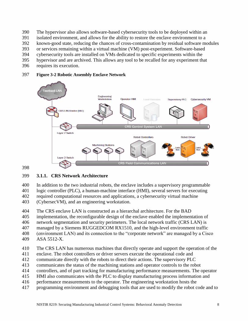
machining operations. An architecture of the robotic enclave network is shown in Figure 3-2. 375
The robot controllers can operate in one of two modes: deployed or virtualized. In the 376
deployed mode, each robot is controlled on a dedicated Dell PowerEdge R420 server running 377
the robot operating system (ROS) on top of Ubuntu Linux. In the virtualized mode, each 378
robot is controlled by virtualized servers within a hypervisor running on a Dell PowerEdge 379
620 server. The deployed mode supports experiments with a pseudo-ideal configuration. The 380
virtualized mode supports experiments with a resource-restricted configuration and can 381
maintain independent demonstration environments. 382
The pseudo-ideal configuration provides the robot controller software with computational 383
resources that are well beyond the minimum requirements for unimpeded operations. 384
Operating in this manner is reserved for experiments that do not require server performance 385
impacts to be measured (e.g., network-specific experiments). The resource-restricted 386
configuration allows the researchers to restrict the available resources to the robot controller 387
software and underlying OS (e.g., memory allocation, available hard-disk space, hard-disk 388
access rates, number of central processing unit [CPU] cores). 389
NISTIR 8219: Securing Manufacturing Industrial Control Systems: Behavioral Anomaly Detection 8
The hypervisor also allows software-based cybersecurity tools to be deployed within an 390
isolated environment, and allows for the ability to restore the enclave environment to a 391
known-good state, reducing the chances of cross-contamination by residual software modules 392
or services remaining within a virtual machine (VM) post-experiment. Software-based 393
cybersecurity tools are installed on VMs dedicated to specific experiments within the 394
hypervisor and are archived. This allows any tool to be recalled for any experiment that 395
requires its execution. 396
Figure 3-2 Robotic Assembly Enclave Network 397
398
3.1.1. CRS Network Architecture 399
In addition to the two industrial robots, the enclave includes a supervisory programmable 400
logic controller (PLC), a human-machine interface (HMI), several servers for executing 401
required computational resources and applications, a cybersecurity virtual machine 402
(CybersecVM), and an engineering workstation. 403
The CRS enclave LAN is constructed as a hierarchal architecture. For the BAD 404
implementation, the reconfigurable design of the enclave enabled the implementation of 405
network segmentation and security perimeters. The local network traffic (CRS LAN) is 406
managed by a Siemens RUGGEDCOM RX1510, and the high-level environment traffic 407
(environment LAN) and its connection to the “corporate network” are managed by a Cisco 408
ASA 5512-X. 409
The CRS LAN has numerous machines that directly operate and support the operation of the 410
enclave. The robot controllers or driver servers execute the operational code and 411
communicate directly with the robots to direct their actions. The supervisory PLC 412
communicates the status of the machining stations and operator controls to the robot 413
controllers, and of part tracking for manufacturing performance measurements. The operator 414
HMI also communicates with the PLC to display manufacturing process information and 415
performance measurements to the operator. The engineering workstation hosts the 416
programming environment and debugging tools that are used to modify the robot code and to 417
NISTIR 8219: Securing Manufacturing Industrial Control Systems: Behavioral Anomaly Detection 9
give terminal-level access to other machines within the enclave. The HyperV server provides 418
server virtualization to the enclave, allowing researchers to create servers on demand, as 419
required by specific software tools or packages. 420
3.2. Process Control System 421
The PCS enclave emulates an industrial continuous manufacturing system, a manufacturing 422
process to produce or process materials continuously, where the materials are continuously 423
moving, going through chemical reactions, or undergoing mechanical or thermal treatment. 424
Continuous manufacturing usually implies a 24/7 (24 hours a day, seven days a week) 425
operation with infrequent maintenance shutdowns and is contrasted with batch 426
manufacturing. Examples of continuous manufacturing systems are chemical production, oil 427
refining, natural-gas processing, and wastewater treatment [9]. An architecture of the PCS 428
network is depicted in Figure 3-3. 429
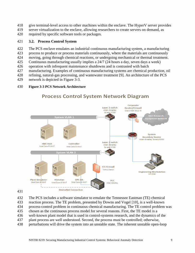
Figure 3-3 PCS Network Architecture 430
431
The PCS includes a software simulator to emulate the Tennessee Eastman (TE) chemical 432
reaction process. The TE problem, presented by Downs and Vogel [10], is a well-known 433
process-control problem in continuous chemical manufacturing. The TE control problem was 434
chosen as the continuous process model for several reasons. First, the TE model is a 435
well-known plant model that is used in control-systems research, and the dynamics of the 436
plant process are well understood. Second, the process must be controlled; otherwise, 437
perturbations will drive the system into an unstable state. The inherent unstable open-loop 438

NISTIR 8219: Securing Manufacturing Industrial Control Systems: Behavioral Anomaly Detection 10
operation of the TE process model presents a real-world scenario in which a cybersecurity 439
attack could represent a real risk to human safety, environmental safety, and economic 440
viability. Third, the process is complex, nonlinear, and has many degrees of freedom by 441
which to control and perturb the dynamics of the process. Finally, numerous simulations of 442
the TE process have been developed with readily available reusable code. We chose the 443
University of Washington Simulink controller design by Ricker [11]. The Ricker Simulink 444
model was chosen for its multiloop control architecture, making distributed control 445
architectures viable. It accurately matches the Downs and Vogel model, and the control code 446
is easily separable from the plant code. 447
The TE process model is illustrated in Figure 3-4. Downs and Vogel did not reveal the actual 448
substances used in the process; instead, they used generic identifiers for each substance. The 449
process produces two products (G and H) from four reactants (A, C, D, and E). The process 450
is defined as irreversible and exothermic, and the reaction rates of the four reactants are a 451
function of the reactor temperature. The process is broken down into five major operations: a 452
reactor, a product condenser, a vapor-liquid separator, a product stripper, and a recycle 453
compressor. The PCS is housed in a 19-inch rack system. The model has 12 actuators for 454
control and 41 sensors for monitoring. The process description is summarized below. 455
As previously mentioned, the reaction rates of the reactants are a function of the reactor 456
temperature. The gaseous reactants are combined in the reactor to form liquid products. The 457
reactor temperature is then cooled by using an internal cooling bundle. The reactor product 458
passes through the condenser to the separator. The vapor-liquid separator then separates 459
unreacted gases from the liquid products. The unreacted gases are sent back to the reactor by 460
the recycle compressor. The remaining reactants are removed in a stripping column. Finally, 461
the two end products are sent downstream for further refining and separation. 462
Figure 3-4 TE Process Control Model 463
464

NISTIR 8219: Securing Manufacturing Industrial Control Systems: Behavioral Anomaly Detection 11
3.2.1. PCS Network Architecture 465
The PCS includes a software simulator to emulate the TE chemical reaction process. The 466
simulator is written in C code and is executed on a computer running Windows 7. In 467
addition, the system includes a PLC, a software controller implemented in MATLAB, an 468
HMI, an object linking and embedding for process control (OPC) data access (DA) server, a 469
data historian, an engineering workstation, and several virtual LAN switches and network 470
routers. 471
The PCS network is segmented from the demonstration network via a boundary router. The 472
router is using a dynamic routing protocol, Open Shortest Path First, to communicate with 473
the main demonstration environment router. All network traffic needs to go through the 474
boundary router to access the main demonstration network. There are two virtual network 475
segments in the system. Each network is managed by an Ethernet switch. The HMI and the 476
controller are in Virtual Local Area Network (VLAN)-1, while the plant simulator, data 477
historian, OPC DA server, and PLC are in VLAN-2. VLAN-1 simulates a central 478
control-room environment in which the HMI and the controllers are virtually located in the 479
same network segment. VLAN-2 simulates the process operation environment, which 480
typically consists of the operating plant, PLCs, OPC DA server, and data historian. These 481
network switches and routers are highly reconfigurable and therefore allow the system to 482
implement various network topologies for demonstration. 483
A Tofino Xenon security appliance, a firewall specially designed for ICS application, is 484
installed to protect the PLC. The firewall rules are configured to allow only certain network 485
nodes and specific protocols to access the PLC, and to deny all other traffic. All of the 486
computer nodes in the system have the Windows firewall enabled. Rules are configured to 487
allow computer access to only traffic specific to their applications. For example, the firewall 488
of the OPC DA server computer allows only a restricted range of remote procedure call and 489
Distributed Component Object Model (DCOM) ports for the OPC clients to access, and it 490
restricts the source Internet Protocol (IP) address of the OPC clients. 491
The plant simulator is implemented in C code, which was based on the Fortran code 492
originally developed by Downs and Vogel. The plant simulator requires a controller to 493
provide a control loop in order to operate continuously. A decentralized controller 494
implemented in Simulink, developed by Ricker, is used as the process controller. The Ricker 495
implementation accurately matches the plant simulator, and the controller is a separate 496
software process that runs on a separate computer from the plant simulator. To provide 497
communication between the plant simulator and the controller, a hardware PLC with an 498
industrial network protocol capability is used. The industrial network protocol is used to 499
communicate between the plant simulator and the PLC. The plant simulator sends its sensor 500
information to the controller, and the controller algorithm uses the sensor inputs to compute 501
the desired values of the actuators and then sends those values back to the plant simulator. 502
In the plant simulator computer, a multinode DeviceNet card was installed. DeviceNet is a 503
common industrial protocol that is used in the automation industry to exchange data between 504
control devices. The multinode card allows a single hardware device to emulate multiple 505
virtual DeviceNet nodes. In this case, each sensor and actuator point are dedicated nodes. 506
Therefore, 53 virtual nodes (41 for sensors and 12 for actuators) were configured in the 507

NISTIR 8219: Securing Manufacturing Industrial Control Systems: Behavioral Anomaly Detection 12
system. A software interface was developed to send and receive sensor and actuator values 508
between the plant simulator and the PLC, through DeviceNet. An OPC DA server is running 509
on a Windows 7 computer, acting as the main data gateway for the PLC. The PLC 510
communicates to the OPC DA server to update and retrieve all of the sensor and actuator 511
information, respectively. This sensor and actuator information is also known as a “tag” in 512
PLC terminology. The controller has a MATLAB Simulink interface that directly 513
communicates with the OPC DA server. 514
An HMI and a data historian are implemented in the system. The HMI provides a graphical 515
user interface (GUI) to present information to an operator or user about the state of the 516
process. The data historian serves as the main database to record all of the process sensor and 517
actuator information. Both the HMI and the data historian have built-in interfaces to establish 518
connections to the OPC DA server to access all of the process information. An engineering 519
workstation is used in the system for engineering support, such as PLC development and 520
control, HMI development and deployment, and data-historian data retrieval. 521
All systems in the PCS are synchronized with the NTP server environment. A network 522
packet analyzer tool is installed in all of the computers in the system to capture and analyze 523
network packets. Other specialized software tools are also used to monitor the system. For 524
example, an OPC data analyzer is used to monitor OPC data exchange, and DeviceNet 525
logging is used to log DeviceNet-level traffic. 526
3.3. Behavioral Anomaly Detection Capabilities Demonstrated 527
The BAD capability was demonstrated by installing single products into each environment. 528
Only one product was installed and performing BAD at any given time. The BAD capability 529
is achieved by three different detection methods: network-based, agent-based, and 530
historian/sensor-based. CyberX and SecurityMatters SilentDefense demonstrated 531
network-based detection. Secure-NOK’s SNOK Detector demonstrates agent-based 532
detection. The OSIsoft Process Information (PI) System’s PI Data Archive (historian) 533
demonstrates sensor-based detection from historian data. 534
3.3.1. SecurityMatters SilentDefense 535
SecurityMatters SilentDefense utilizes sensors to passively sniff traffic at the Layer 3 peer-536
to-peer switches to monitor critical networks for anomalies. The SilentDefense product also 537
uses a command center to manage and collect data from all sensors at an enterprise site. The 538
installation and configuration procedures undertaken for the SecurityMatters SilentDefense 539
product are provided in Appendix A. 540
3.3.2. Secure-NOK SNOK 541
Secure-NOK’s SNOK is a cybersecurity monitoring and detection system tailored for 542
industrial networks and control systems. SNOK utilizes nonintrusive endpoint monitoring 543
agents and passive network monitoring from Layer 2 and Layer 3 switches. The SNOK 544
network intrusion detection system (IDS) comes preinstalled on an appliance, and endpoint 545
monitoring agents are integrated into the asset owner’s environment. The installation and 546
configuration procedures undertaken for the Secure-NOK SNOK appliance are provided in 547
Appendix B. 548

NISTIR 8219: Securing Manufacturing Industrial Control Systems: Behavioral Anomaly Detection 13
3.3.3. CyberX 549
The CyberX platform delivers continuous operational technology (OT) threat monitoring and 550
asset discovery, combining a deep understanding of industrial protocols, devices, and 551
applications with OT-specific behavioral analytics, threat intelligence, risk and vulnerability 552
management, and automated threat modeling. The platform is delivered as a preconfigured 553
appliance, including the IP address, subnet mask, default gateway, and Domain Name 554
System (DNS) servers utilized in the build environment. The installation and configuration 555
procedures undertaken for the CyberX appliance are provided in Appendix C. 556
3.3.4. OSIsoft PI Data Archive 557
The OSIsoft PI System’s PI Data Archive is a component of the PI System that retrieves, 558
archives, and enables high-performance data storage and rapid retrieval by using minimal 559
disk space. The installation and configuration procedures undertaken for OSIsoft’s PI System 560
software are provided in Appendix D. 561
3.4. Behavioral Anomaly Detection Methods and Security Functions 562
Table 3-1 identifies methods used in this project and provides a mapping between the method 563
type, the function performed, and the security control(s) provided. Refer to Table 2-1 for an 564
explanation of the Cybersecurity Framework subcategory codes. 565
Table 3-1 BAD Methods and Security Functions 566
Type Function CSF Subcategories
Network-based Identifies, monitors, and reports anomalous ICS
traffic that might indicate a potential intrusion.
Collects ICS network traffic via passive
(agentless) monitoring. The system uses deep
packet inspection to dissect traffic from both
serial and Ethernet control network equipment.
DE.AE-1,
DE.AE-2,
DE.AE-5,
DE.CM-1,
DE.CM-4,
DE.CM-7,
DE.DP-4
Historian/sensor-based Gathers raw data, records process data, and
creates calculations.
Provides monitoring and performance alerts of
the process historian. The historian accesses
historical data and consolidates it with current,
real-time data. It allows for investigating
intermittent issues, troubleshooting equipment
failures, comparing current versus past
production performance, and measuring
new-plant startups against existing facilities.
Does not support a NIST
Cybersecurity Framework
subcategory in and of itself.
It provides the data to be
monitored by the ICS
behavior monitor (next
item).
Related subcategories:
DE.AE-5,
DE.CM-1

NISTIR 8219: Securing Manufacturing Industrial Control Systems: Behavioral Anomaly Detection 14
Type Function CSF Subcategories
Agent-based Identifies, monitors, and reports anomalous ICS
traffic that might indicate a potential intrusion.
Uses nonintrusive software agents to monitor the
ICS network that requires no updating. The
network IDS passively collects data from the
ICS / Supervisory Control and Data Acquisition
(SCADA) network via Switch Port Analyzer
(SPAN)/mirroring ports. The nonintrusive
host-monitoring agents collect data from within
endpoints. The agents send event information to
the detector, which looks for early warnings of
cybersecurity attacks, and alerts on the anomalies
detected by using a web interface.
DE.AE-1,
DE.AE-2,
DE.AE-5,
DE.CM-1,
DE.CM-4,
DE.CM-7,
DE.DP-4
567
3.5. Typographic Conventions 568
Table 3-2 presents the typographic conventions used in this NISTIR’s descriptions of 569
scenarios and demonstration findings. 570
Table 3-2 Typographic Conventions 571
Typeface/Symbol Meaning Example
Italics file names and path names;
references to documents that are
not hyperlinks; new terms; and
placeholders
For detailed definitions of terms, see
the CSRC Glossary.
Bold names of menus, options,
command buttons, and fields
Choose File > Edit.
Monospace command-line input, on-screen
computer output, sample code
examples, and status codes
Mkdir
Monospace Bold command-line user input
contrasted with computer output
service sshd start
blue text link to other parts of the
document, a web Uniform
Resource Locator (URL), or an
email address
All publications from NIST’s NCCoE are
available at https://www.nccoe.nist.gov.
4. Demonstration Scenarios and Findings 572
With both the robotic and process-control infrastructures available for immediate use, the 573
implementation of the BAD capabilities consisted of installing and integrating a single tool 574
with the existing infrastructures. The BAD products are installed within the demonstration 575
environment’s DMZ of the existing infrastructure. 576

NISTIR 8219: Securing Manufacturing Industrial Control Systems: Behavioral Anomaly Detection 15
4.1. Network-Based Behavioral Anomaly Detection 577
Network-based anomaly detection requires the aggregation of all network traffic into a single 578
collection point. Multiple appliances can also be used with centralized management to collect 579
network traffic data from different zones and sites. Network traffic is examined and 580
compared with a preexisting baseline, which is assumed to be normal at the time that it is 581
captured. Should the network traffic show deviations from this baseline or show any other 582
types of behavior considered suspicious or unauthorized, an alert will be generated based on 583
preconfigured parameters. 584
During network-based anomaly detection, network traffic from the CRS and PCS LAN 585
networks is aggregated at the demonstration environment’s DMZ via SPAN ports. At the 586
demonstration environment’s DMZ, the traffic is inspected by the CyberX and SilentDefense 587
platforms. Once a baseline of network traffic is established as normal, this aggregation of 588
traffic can show deviations from the baseline, triggering an alert based on preconfigured 589
parameters. Parameters can be configured to trigger alerts relating to network-traffic 590
deviations, user-behavior deviations, volumetric deviations, and protocol deviations. 591
4.2. Agent-Based Behavioral Anomaly Detection 592
Agent-based anomaly detection combines some of the features of network-based anomaly 593
detection with the nonintrusive monitoring of endpoints. Agent-based anomaly detection uses 594
distributed software agents installed onto or close to devices, such as servers, HMIs, network 595
switches, and controllers. Agents collect and preprocess device information, such as the use 596
of removable media; logged-in users; ingress/egress traffic; device configurations; process 597
and program details; and device parameters, such as memory, disk, and processor utilization. 598
The collected information is sent securely to a detection engine. The detection engine alerts 599
on deviations from preconfigured security policies and preexisting baselines. The preexisting 600
baselines are reviewed and accepted as normal at the time that they are captured. 601
During agent-based anomaly detection, the behavior of Windows 7 devices in the PCS 602
network, and of Ubuntu Linux devices in the CRS network, was monitored. The host agent 603
information and network traffic are inspected by the Secure-NOK SNOK Detector. Once a 604
baseline of the device configuration and behaviors is established as normal, deviations will 605
trigger alerts. 606
4.3. Historian-Based and Sensor-Based Behavioral Anomaly Detection 607
Operational historian/sensor-based anomaly detection relies on the collection of sensor data 608
into ICS network components, such as operational historians. Because historians are 609
constantly being fed real-time operational data, which has already been configured within 610
operational bounds, or set points, any deviations from these thresholds will produce an alert 611
that can be captured. Typically, this would be considered an operational anomaly. OSIsoft’s 612
PI Data Archive performs historian/sensor-based detection. 613

NISTIR 8219: Securing Manufacturing Industrial Control Systems: Behavioral Anomaly Detection 16
4.4. Demonstration Results and Findings 614
The demonstration effort examined 16 classes of BAD. These 16 classes for which 615
anomalous events were successfully detected include the detection of the following items: 616
• plaintext passwords 617
• user authentication failures 618
• new network devices 619
• abnormal network traffic between devices 620
• internet connectivity 621
• data exfiltration 622
• unauthorized software installations 623
• PLC firmware modifications 624
• unauthorized PLC logic modifications 625
• file transfers between devices 626
• abnormal ICS protocol communications 627
• malware 628
• denial of service (DoS) 629
• abnormal manufacturing system operations 630
• port scans/probes 631
• environmental changes 632
Each of the demonstration events addressed threats that would not normally be detected by 633
current security tools that involve monitoring system behaviors for predefined out-of-634
specification settings or readings or that involve threat signatures (information elements 635
previously identified as being associated with threats or vulnerability characteristics, such as 636
with an IDS or an intrusion protection system). Network-based, agent-based, and 637
historian/sensor-based detection capabilities were examined. Each product that was 638
demonstrated performed as expected. 639
As indicated in Section 4.1, individual products were examined in different scenarios, and 640
not all types of detection events were examined in each scenario. As a result, no comparison 641
of product detection capabilities can usefully be made or is appropriate to this NISTIR. 642
The installation, configuration, anomaly scenarios, and results for each tool are described in 643
the appendixes of this document. 644
5. Conclusion 645
The goal of this project was to demonstrate BAD techniques that businesses can implement 646
and use to strengthen the cybersecurity of their manufacturing processes. The BAD project 647
demonstrated three different detection methods: network-based, agent-based, and operational 648
historian/sensor-based. We have shown that BAD techniques can serve as a key security 649
component in sustaining ICS operations. This NISTIR illustrates the use of the different 650
BAD capabilities, to provide a better understanding of what each of the techniques offers and 651
how to apply each of these techniques in different ICS network environments. 652

NISTIR 8219: Securing Manufacturing Industrial Control Systems: Behavioral Anomaly Detection 17
Appendix A. SecurityMatters SilentDefense Supplemental Information 653
SecurityMatters SilentDefense utilizes sensors to passively sniff traffic at the Layer 3 peer-654
to-peer switches to monitor critical networks for anomalies. The SilentDefense product also 655
uses a command center to manage and collect data from all network-based sensors within a 656
manufacturing system. 657
A.1. Build Architecture 658
The SilentDefense dedicated appliance was physically installed in the measurement rack of 659
the Cybersecurity for Smart Manufacturing Systems (CSMS) environment. Three existing 660
Switch Port Analyzer (SPAN) ports from each system (collaborative robotic system [CRS] 661
and process control system [PCS]) were connected to dedicated network interfaces on the 662
appliance, for a total of six SPAN ports. The SPAN port connections to the appliance, within 663
the PCS and CRS networks, are shown in Figure A-1 and Figure A-2, respectively. 664
The appliance network connection was connected to the demilitarized zone (DMZ) network 665
located in the test bed’s measurement rack, to isolate the appliance’s network traffic from the 666
rest of the network. Engineering laptops were used to interface with the SilentDefense 667
graphical user interface (GUI) via network connections to the DMZ. More information 668
regarding the specific configuration of the test-bed network can be found in Section 3. 669
Figure A-1 SPAN Port Connections to the SilentDefense Appliance in the PCS 670
671

NISTIR 8219: Securing Manufacturing Industrial Control Systems: Behavioral Anomaly Detection 18
Figure A-2 SPAN Port Connections to the SilentDefense Appliance in the CRS 672
673
A.2. Installation and Configuration 674
Physical hardware and software were provided by SecurityMatters for this demonstration. 675
After the hardware appliance was received, it was installed into the CSMS test bed. Soon 676
after the initial installation, engineers from SecurityMatters arrived on site to complete the 677
installation and configuration of the tool. The following subsections describe the steps taken 678
to install and configure the appliance. 679
A.2.1. Hardware 680
The SilentDefense appliance was installed as a bundle (with the sensor and the command 681
center on the same hardware). Typically, these functions are separated in production 682
installations; however, because this was a lab system, the bundle was sufficient for the 683
demonstration environment. The bundled hardware was a Dell R630 1U Rackmount Server 684
with the following specifications: 685
• central processing unit (CPU): Intel Xeon E5-2620, 2.4 gigahertz, 5-megabyte (M) 686
cache, 6C/12T (6 cores and 12 threads) 687
• random-access memory: 32 gigabytes (GB), registered dual in-line memory module, 688
2,400 megatransfers per second 689
• hard drive: 800 GB, solid-state drive 690
• redundant array of independent disks controller: PERC H730, 1 GB cache 691
• sniffing network interface card (NIC): Intel i350 Quad Port Peripheral Component 692
Interconnect Express Card 693
A.2.2. Operating System 694
SilentDefense 3.11.1 uses the Ubuntu 16.04.3 Long-Term Support (LTS) Server operating 695
system (OS), which is modified with two scripts. First, there is a SecurityMatters OS update 696
script to update libraries to the latest versions and to install some new libraries necessary for 697
SilentDefense operation. The OS is then modified with a main-configuration script, which 698
NISTIR 8219: Securing Manufacturing Industrial Control Systems: Behavioral Anomaly Detection 19
hardens the OS by performing operations, such as disabling users, setting iptables, and 699
setting the update repository addresses to local hard-drive folders (so that, automatic updates 700
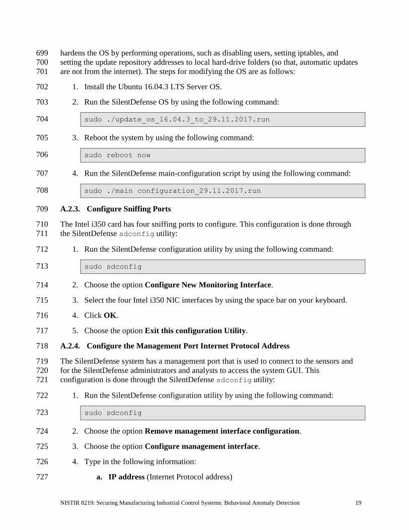
are not from the internet). The steps for modifying the OS are as follows: 701
1. Install the Ubuntu 16.04.3 LTS Server OS. 702
2. Run the SilentDefense OS by using the following command: 703
sudo ./update_os_16.04.3_to_29.11.2017.run 704
3. Reboot the system by using the following command: 705
sudo reboot now 706
4. Run the SilentDefense main-configuration script by using the following command: 707
sudo ./main configuration_29.11.2017.run 708
A.2.3. Configure Sniffing Ports 709
The Intel i350 card has four sniffing ports to configure. This configuration is done through 710
the SilentDefense sdconfig utility: 711
1. Run the SilentDefense configuration utility by using the following command: 712
sudo sdconfig 713
2. Choose the option Configure New Monitoring Interface. 714
3. Select the four Intel i350 NIC interfaces by using the space bar on your keyboard. 715
4. Click OK. 716
5. Choose the option Exit this configuration Utility. 717
A.2.4. Configure the Management Port Internet Protocol Address 718
The SilentDefense system has a management port that is used to connect to the sensors and 719
for the SilentDefense administrators and analysts to access the system GUI. This 720
configuration is done through the SilentDefense sdconfig utility: 721
1. Run the SilentDefense configuration utility by using the following command: 722
sudo sdconfig 723
2. Choose the option Remove management interface configuration. 724
3. Choose the option Configure management interface. 725
4. Type in the following information: 726
a. IP address (Internet Protocol address) 727

NISTIR 8219: Securing Manufacturing Industrial Control Systems: Behavioral Anomaly Detection 20
b. subnet mask 728
c. gateway 729
d. Domain Name System server(s) 730
5. Press OK. 731
A.2.5. Configure the SPAN Ports on Layer 3 Network Switches 732
The SilentDefense passive monitoring system uses SPAN ports to intercept and analyze 733
network packets. The process to configure a SPAN port varies among different makes and 734
models of networking hardware. For SPAN port configuration information, consult the 735
current configuration manual or user guide for the specific networking hardware. 736
A.2.6. Log into SilentDefense 737
The SilentDefense GUI has a default username and password of admin. Upon the first login, 738
you are required to change the password to something more secure. The SilentDefense 739
software will not allow the new username and password to be the same. 740
1. Browse to the SilentDefense GUI from a web browser, using the following Uniform 741
Resource Locator (URL): 742
https://<mgmt_ip_address> 743
2. Type the username admin and the password admin in the login fields, and then click 744
Sign in. 745
3. A new window pops up, requiring you to change the password. Type in a new 746
password that meets the following requirements: 747
a. Contains eight characters minimum 748
b. Does not contain the account name 749
c. Contains at least three character groups (e.g., uppercase, lowercase, number, 750
special) 751
4. Click Apply. 752
5. The dashboard now appears, and you can begin to use SilentDefense. 753
A.3. Anomaly Scenarios 754
The network-based anomaly detection method was demonstrated for the scenarios detailed in 755
the following subsections. Each scenario includes a description of the anomaly, a detailed 756
description of how each demonstration event was conducted in the CSMS environment, and 757
the observed results. 758

NISTIR 8219: Securing Manufacturing Industrial Control Systems: Behavioral Anomaly Detection 21
For the sake of brevity, only a subset of the alerts observed during each anomaly scenario is 759
shown. However, each anomaly scenario includes a screenshot of the alerts summary (or 760
aggregated summary) observed after the anomaly scenario had completed. 761
A.3.1. Unencrypted Passwords Are Used to Access a Networking Device 762
Unencrypted or plaintext passwords transmitted over a network are a vulnerability for 763
industrial control system (ICS) networks. If packets containing these credentials are 764
intercepted, then the passwords can be easily unmasked and can be used to obtain 765
unauthorized access to devices or services that use those credentials. This vulnerability can 766
be amplified if multiple devices utilize the same credentials. 767
This anomaly was executed on the PCS. The network switches and router provide a Telnet 768
service for remote management. This protocol transmits user credentials as plaintext. A 769
Telnet connection was opened between the engineering workstation and Virtual Local Area 770
Network (VLAN)-1 by using the open-source PuTTY [12] client. 771
772
773
A.3.2. Transmission Control Protocol Connection Requests Are Received from 774
the Internet 775
When attempting to form a connection by using the transmission control protocol (TCP), a 776
connection request first must be sent to the server. If a TCP connection request is received 777
from the internet (i.e., it has a public Internet Protocol [IP] address), then this can indicate a 778
network misconfiguration, a device misconfiguration, or an unidentified internet connection 779
within the lower levels of the ICS network. 780

NISTIR 8219: Securing Manufacturing Industrial Control Systems: Behavioral Anomaly Detection 22
This anomaly was executed on the CRS. The packet manipulation tool Scapy [13] was used 781
with Python [14] to create a TCP SYN packet with a public IP as the source address 782
(129.6.1.10) and with the programmable logic controller (PLC) IP as the destination address, 783
and was injected into the CRS local area network (LAN). 784
785
786
A.3.3. Data Exfiltration Between ICS Devices via Server Message Block 787
Vulnerable devices within an ICS network can be used as a pivot to bring higher-value 788
targets within reach to exfiltrate data (e.g., using a vulnerable Internet of Things device to 789
pivot and leverage attacks against a PLC on the same network). Monitoring for abnormal 790
communication patterns between ICS devices can help detect these types of attacks, 791
especially if the affected devices do not communicate during normal operations. 792

NISTIR 8219: Securing Manufacturing Industrial Control Systems: Behavioral Anomaly Detection 23
This anomaly was executed on the PCS. An unauthorized Windows File Share (using the 793
Server Message Block protocol) was configured between the human-machine interface 794
(HMI) server and the engineering workstation. Three types of files were transferred over the 795
share: a comma-separated values (CSV) file, a Microsoft Excel workbook (XLSX) file, and 796
an Adobe Portable Document File (PDF). 797
798
799
A.3.4. Data Exfiltration to the Internet via File Transfer Protocol 800
Attacks against ICS, with the goal of information gathering, must (at some point) attempt to 801
exfiltrate the data from the ICS network, likely utilizing the internet as a transport 802
mechanism. Monitoring for ICS devices communicating over the internet can help detect 803
data exfiltration events, especially if the affected device does not normally communicate over 804
the internet. Depending on the protocol used for exfiltration, the file contents and/or data 805
being exfiltrated may be ascertainable (e.g., file names, file types, data transferred using the 806
File Transfer Protocol [FTP]), providing insight into the impact of the anomaly. 807
This anomaly was executed on the PCS. An FTP server was installed and configured on a 808
server with an internally routed public IP address (129.6.1.2). The FileZilla FTP client [15] 809
was installed on the historian server and was used to transfer three types of files to the 810
simulated “internet-based” FTP server: a CSV file, an XLSX file, and an Adobe PDF. 811

NISTIR 8219: Securing Manufacturing Industrial Control Systems: Behavioral Anomaly Detection 24
812
813
A.3.5. Unauthorized Device Is Connected to the Network 814
It is important to identify all devices on the ICS network, for a complete risk analysis and for 815
minimizing potential attack vectors. The detection of unauthorized devices attached to the 816
ICS network may indicate anomalous activity. These unauthorized devices are important to 817
find and remove, especially because the purpose of an unauthorized device is unknown and 818
may be malicious. 819
This anomaly was executed on the CRS. The engineering laptop (Windows 7 OS) was 820
removed from the network during the baseline phase of the tool configuration and was later 821
connected to the CRS LAN to execute the anomaly. After the initial connection, background 822
traffic was automatically generated onto the network by the laptop. 823

NISTIR 8219: Securing Manufacturing Industrial Control Systems: Behavioral Anomaly Detection 25
824
825
A.3.6. Loss of Communications with Modbus TCP Device 826
ICS devices must exhibit high availability to support manufacturing operations. This quality 827
becomes more important as the speed of manufacturing operations increases (i.e., short cycle 828
times). If an ICS device hosting a network service becomes unavailable during 829
manufacturing operations, then this may be a sign of anomalous activity and should be 830
investigated. Loss of communications with a device or service may be caused by a multitude 831
of anomalies, including device restarts, software faults, high network utilization, and an 832
increased processing load on the device. 833

NISTIR 8219: Securing Manufacturing Industrial Control Systems: Behavioral Anomaly Detection 26
This anomaly was executed on the CRS. A firewall rule was added to the Linux iptables 834
(Linux kernel firewall) on Machining Station 1 to block all incoming packets on Modbus 835
TCP Port 502. The firewall replied with a TCP reset for each incoming packet or connection 836
request, to make it appear as is if the Modbus server had terminated and the TCP socket was 837
closed. 838
839
840
A.3.7. Brute-Force Password Attack Against an ICS Device 841
Authentication systems that are not rate-restricted may be vulnerable to password-guessing 842
attacks, especially if the default credentials of the device have not been changed. Compiled 843
lists containing default user credentials are freely available on the internet, as are lists of 844
commonly used usernames and passwords. Given enough time, an attacker may be able to 845
access vulnerable systems by using a brute-force password attack. 846
This anomaly was executed on the CRS. The software Nmap [16] was used to generate the 847
brute-force password attack by using the script http-brute. The attack was pointed at an 848
Apache [17] Hypertext Transfer Protocol (HTTP) server on Machining Station 4, containing 849
a directory that was protected by HTTP basic authentication. The HTTP server was not 850
configured to limit the number of authentication attempts. 851
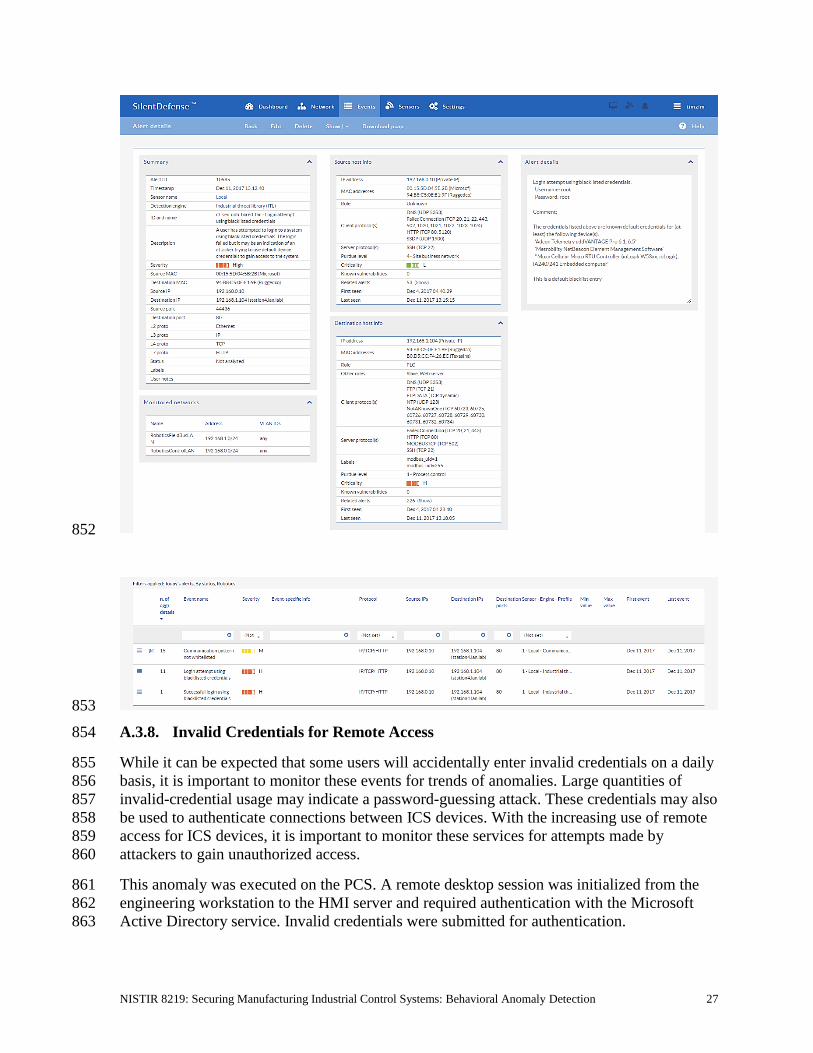
NISTIR 8219: Securing Manufacturing Industrial Control Systems: Behavioral Anomaly Detection 27
852
853
A.3.8. Invalid Credentials for Remote Access 854
While it can be expected that some users will accidentally enter invalid credentials on a daily 855
basis, it is important to monitor these events for trends of anomalies. Large quantities of 856
invalid-credential usage may indicate a password-guessing attack. These credentials may also 857
be used to authenticate connections between ICS devices. With the increasing use of remote 858
access for ICS devices, it is important to monitor these services for attempts made by 859
attackers to gain unauthorized access. 860
This anomaly was executed on the PCS. A remote desktop session was initialized from the 861
engineering workstation to the HMI server and required authentication with the Microsoft 862
Active Directory service. Invalid credentials were submitted for authentication. 863

NISTIR 8219: Securing Manufacturing Industrial Control Systems: Behavioral Anomaly Detection 28
864
865
A.3.9. Unauthorized ICS Device Firmware Update 866
Many ICS devices provide services to remotely update firmware over the network. These 867
network services can also provide a mechanism for attackers to replace valid firmware with 868
malicious firmware if the device is not protected. 869
This anomaly was executed on the PCS. The Allen-Bradley PLC implemented in the PCS 870
contains an Ethernet module (1756-EN2T) that allows its firmware to be upgraded and 871
downgraded over Ethernet/IP. The firmware was upgraded or downgraded using the 872
ControlFLASH firmware upgrade tool. 873

NISTIR 8219: Securing Manufacturing Industrial Control Systems: Behavioral Anomaly Detection 29
874
875
A.3.10. Unauthorized HMI Logic Modification 876
Many ICS devices provide services to remotely update control logic over the network. These 877
network services can also provide a mechanism for attackers to replace valid control logic 878
with malicious logic if the device is not protected. This is especially important for HMIs, as 879
they are typically used by operators to monitor and manipulate the manufacturing process in 880
a safe and controlled manner. 881

NISTIR 8219: Securing Manufacturing Industrial Control Systems: Behavioral Anomaly Detection 30
This anomaly was executed on the CRS. The database implemented on the CRS Red Lion 882
HMI (Model G310) was modified and uploaded to the HMI by using the Red Lion Crimson 883
3.0 software. The Modbus TCP registers in the modified database differed slightly from 884
those in the original database. 885
886
887
A.3.11. ICS Device Receives Diagnostic Modbus TCP Function Codes 888
Certain ICS network protocols enable diagnostic access to ICS devices. While this type of 889
functionality enables remote maintenance and diagnostics to authorized personnel, it may 890
also be leveraged by aggressors to compromise ICS devices. 891

NISTIR 8219: Securing Manufacturing Industrial Control Systems: Behavioral Anomaly Detection 31
This anomaly was executed on the CRS. Python [14] was used to create a Modbus TCP 892
message with the diagnostic function code value of 43 (0x2B), known as encapsulated 893
interface transfer. The message was generated by the cybersecurity virtual machine 894
(CybersecVM) and was transmitted to the PLC Modbus server. 895
896
897
A.3.12. ICS Device Receives Undefined Modbus TCP Function Codes 898
Communications that do not conform to the defined specifications of the industrial protocol 899
may cause an ICS device to act in an undefined or unsafe manner. Depending on the 900
manufacturing process and the ICS device, the nonconforming communications may or may 901
not be impactful, but investigation into the cause is warranted. 902
This anomaly was executed on the CRS. Python [14] was used to create a Modbus TCP 903
message with the undefined function code value of 49 (0x31). The message was generated 904
by the CybersecVM and was transmitted to the PLC Modbus server. 905

NISTIR 8219: Securing Manufacturing Industrial Control Systems: Behavioral Anomaly Detection 32
906
907
A.3.13. ICS Device Receives Malformed Modbus TCP Traffic 908
Communications that do not conform to the defined specifications of the industrial protocol 909
may cause an ICS device to act in an undefined or unsafe manner. Depending on the 910
manufacturing process and the ICS device, the nonconforming communications may or may 911
not be impactful, but investigation into the cause is warranted. 912
This anomaly was executed on the CRS. Python [14] was used to create a malformed 913
Modbus TCP message. The message was generated by the CybersecVM and was transmitted 914
to the PLC Modbus server. 915

NISTIR 8219: Securing Manufacturing Industrial Control Systems: Behavioral Anomaly Detection 33
916
917
A.3.14. Illegal Memory Addresses of ICS Device Are Accessed 918
Some industrial protocols (like Modbus) require relative addressing to access ICS device 919
registers. Attackers may attempt to modify illegal memory locations of ICS devices by using 920
these types of industrial protocols or may attempt to cause the ICS device to act in an 921
undefined or unsafe manner by modifying data located in a protected memory location. 922
This anomaly was executed on the CRS. The HMI database was modified to access an illegal 923
register on the PLC Modbus TCP server when the anomaly was activated. The valid Modbus 924
address range for the PLC registers is 0x8000 to 0x80FF. 925

NISTIR 8219: Securing Manufacturing Industrial Control Systems: Behavioral Anomaly Detection 34
926
927
A.3.15. ICS Device Scanning Is Performed on the Network 928
During the reconnaissance phase, an attacker may attempt to locate vulnerable devices in an 929
ICS network and will likely probe for ICS-specific services (e.g., Modbus TCP). Once a 930
vulnerable service is discovered, an attacker may attempt to exploit that service. 931
This anomaly was executed on the CRS. The software Nmap [16] was used to generate the 932
Modbus device scan by using the script modbus-discover [18]. The attack was directed at 933
two ICS devices: the PLC and Machining Station 4. 934

NISTIR 8219: Securing Manufacturing Industrial Control Systems: Behavioral Anomaly Detection 35
935
936

NISTIR 8219: Securing Manufacturing Industrial Control Systems: Behavioral Anomaly Detection 36
Appendix B. Secure-NOK SNOK Supplemental Information 937
Secure-NOK SNOK is a cybersecurity monitoring and detection system tailored for 938
industrial networks and control systems. In the installation, the SNOK network intrusion 939
detection system (IDS) comes preinstalled on an appliance that is integrated into the asset 940
owner’s environment. 941
B.1. Build Architecture 942
Two SNOK dedicated appliances were physically installed in the measurement rack of the 943
Cybersecurity for Smart Manufacturing Systems (CSMS) environment. One appliance was 944
dedicated to the process control system (PCS), and the other appliance was dedicated to the 945
collaborative robotic system (CRS). Three existing Switch Port Analyzer (SPAN) ports from 946
each system (PCS and CRS) were connected to a VERSAstream packet broker (VS-1208BT-947
S) to aggregate the mirrored traffic from the PCS and the CRS into two respective streams, 948
for a total of six SPAN ports. The appliance connections within the PCS and CRS networks 949
are shown in Figure B-1 and Figure B-2, respectively. 950
The PCS appliance network was connected to the demilitarized zone (DMZ) network located 951
in the test bed’s measurement rack, to isolate the appliance’s network traffic from the rest of 952
the network traffic. The engineering laptop was used to interface with the SNOK graphical 953
user interface (GUI) via physical connections to the DMZ. The CRS appliance network was 954
connected to the industrial control system (ICS) local area network (LAN), and the SNOK 955
GUI was accessed via the engineering workstation. More information regarding the specific 956
configuration of the test-bed network can be found in Section 3. 957
Figure B-1 SPAN Port Connections to the SNOK Appliance in the PCS (Including the Hosts 958 with SNOK Agents) 959
960

NISTIR 8219: Securing Manufacturing Industrial Control Systems: Behavioral Anomaly Detection 37
Figure B-2 SPAN Port Connections to the SNOK Appliance in the CRS (Including the Hosts 961 with SNOK Agents) 962
963
B.2. Installation and Configuration 964
Physical hardware appliances and software were provided by Secure-NOK for this 965
demonstration. After the hardware appliances were received, they were installed into the 966
CSMS test bed. Soon after the initial installation, engineers from Secure-NOK arrived on site 967
to complete the installation and configuration of the tool. The following subsections describe 968
the steps taken to install and configure the appliances. 969
B.2.1. Hardware 970
The hardware used included two Siemens SIMATIC industrial personal computers (IPCs) 971
executing the SNOK services: a SIMATIC IPC227E for the PCS and a SIMATIC IPC427E 972
for the CRS. A VERSAstream packet broker (VS-1208BT-S) was used to aggregate the 973
mirrored traffic from the PCS and the CRS into two respective streams, one for each IPC. 974
B.2.2. Windows XP / Windows 7 / Windows Server 2012 Installation 975
The steps in this section describe the installation of SNOK Agents on endpoints with 976
Microsoft Windows operating systems (OSs). 977
1. Launch SNOKAgentSetup.exe from the Windows Agent folder in the installation 978
pack. 979
2. Click Next>. 980
3. Select both components, and then click Next>. 981
4. Input the username and password for administrative privileges, and then click Install. 982

NISTIR 8219: Securing Manufacturing Industrial Control Systems: Behavioral Anomaly Detection 38
5. Modify the configuration file located at <installation directory>\SNOK-983
agent\bin\snokagentconfig.txt to include the following information: 984
a. idAgent: a unique identifier (ID) that will not be used by any other agent that 985
reports to the same SNOK Detector 986
b. detectorIP: the Internet Protocol (IP) address of the SNOK Detector to which 987
the agent will report 988
c. licenseKey: the license key provided for the SNOK Detector 989
B.2.2.1. Start SNOK Agent Manually 990
If the installation did not include selecting Automatically start agent, then follow the steps 991
below to manually start the agent: 992
1. Open the command prompt. 993
2. Change the directory to <installation directory>\bin\ by using the following 994
command: 995
> cd C:\SNOK\bin\ 996
3. Run the agent by using the following command and then pressing the Enter key: 997
> SNOKAgent.exe 998
B.2.2.2. Stop SNOK Agent Manually 999
1. Open the Task Manager. 1000
2. Open the Processes tab. 1001
3. Select the process name SNOKAgent.exe. 1002
4. Click the End Task button. 1003
B.2.3. Ubuntu 12 / Ubuntu 14 Installation 1004
1. Copy the file snoknetmonagent_<version>.deb into the /home directory of the IPC. 1005
2. Add the Debian Wheezy universe to the apt sources file by using the following 1006
command: 1007
> sudo echo “deb http://httpredir.debian.org/debian wheezy 1008 main” >> /etc/apt/sources.list 1009
3. Install the libpcap-dev package by using the following command: 1010
> sudo apt-get install libpcap-dev 1011

NISTIR 8219: Securing Manufacturing Industrial Control Systems: Behavioral Anomaly Detection 39
4. Install the SNOK Agent from the Debian software package file by using the 1012
following command: 1013
> sudo dpkg -I ~/snoknetmonagent_<version>.deb 1014
5. Modify the configuration file snok-netmonconfig.txt located in the directory 1015
/etc/default/ to include the following information: 1016
a. idAgent: a unique ID that will not be used by any other agent that reports to 1017
the same SNOK Detector 1018
b. detectorIP: the IP address of the SNOK Detector to which the agent will 1019
report 1020
c. licenseKey: the license key provided for the SNOK Detector 1021
B.2.4. SNOK Detector Configuration 1022
The SNOK Detector comes installed as part of a preconfigured appliance, requiring final 1023
configuration before integration into the asset owner’s environment. The following 1024
configuration must be completed on the appliance before installation: 1025
1. Obtain a license key from Secure-NOK. The media access control (MAC) address of 1026
the network interface is needed to generate the license. On the appliance, execute the 1027
following command to obtain the address, which will be the hexadecimal number 1028
after HWaddr, in the format of xx:xx:xx:xx:xx:xx: 1029
sudo ifconfig eth0 1030
2. Copy the license key file snoklicense.key to the directory /home/snok/. 1031
3. Start the configuration software by using the following command: 1032
> sudo /usr/share/snok/snok-config.sh 1033
4. Ensure that 1 (VMs Installation) SNOK Detector with local Visualizer is highlighted, 1034
and then press the Enter key. 1035
5. On the Database VM IP page, enter the IP address of the preconfigured appliance, 1036
and then press the Enter key. 1037
6. On the Detector mode page, ensure the messages received are not forwarded 1038
(isolated) and is selected, and then press the Enter key. 1039
7. On the Date-Time Synchronization page, select 1 Enter IP for Simple Network 1040
Time Protocol Server (Network Time Protocol [NTP] / Simple Network Time 1041
Protocol [SNTP] server available), and then press the Enter key. 1042
8. On the NTP/SNTP IP page, type the IP address of the NTP server, and then press the 1043
Enter key. The lab NTP server (10.100.0.15) was used for the build environment. 1044

NISTIR 8219: Securing Manufacturing Industrial Control Systems: Behavioral Anomaly Detection 40
9. On the External Event Reporting page, select any reporting methods, and then press 1045
the Enter key. The build configuration did not require any external reporting 1046
(e.g., syslog, email), so the option 3 Go to next step was selected. 1047
10. When prompted, enter the database password to enable the automated configuration. 1048
11. Start the snok-box service by using the following command: 1049
> sudo service snok-box start 1050
12. Start the snok-dumper service by using the following command: 1051
> sudo service snok-dumper start 1052
B.3. Anomaly Scenarios 1053
The agent-based anomaly detection method was demonstrated for the scenarios detailed in 1054
the following subsections. Each scenario includes a description of the anomaly, a detailed 1055
description of how each demonstration event was conducted in the CSMS environment, and 1056
the observed results. 1057
For the sake of brevity, only a subset of the alerts observed during the demonstration is 1058
shown. However, each anomaly scenario includes a screenshot of the alerts summary 1059
observed after the anomaly scenario had completed. 1060
B.3.1. Web Browser Is Used to Access the Internet 1061
The detection of unauthorized internet traffic on ICS networks is important for mitigating 1062
risk to the manufacturing system. Internet-accessible network connections introduce a 1063
gateway for malware into the ICS network, as well as a gateway for sensitive manufacturing 1064
system data to be exfiltrated out of the ICS network. 1065
This anomaly was executed on the CRS. A Hypertext Transfer Protocol (HTTP) server was 1066
installed and configured on a server with an internally routed public IP address (129.6.1.2). 1067
The Firefox web browser was used to connect to a web page, from the engineering 1068
workstation to the internet-based HTTP server. 1069
1070
1071
1072

NISTIR 8219: Securing Manufacturing Industrial Control Systems: Behavioral Anomaly Detection 41
B.3.2. Data Exfiltration to the Internet via HTTP 1073
Attacks against ICS, with the goal of information gathering, must (at some point) attempt to 1074
exfiltrate sensitive or proprietary data from the ICS network, potentially utilizing the internet 1075
as a transport mechanism. Monitoring for ICS devices communicating to other devices over 1076
the internet can help detect data exfiltration events, especially if the affected device does not 1077
normally communicate over the internet. 1078
This anomaly was executed on the CRS. An HTTP server and the PHP (Hypertext 1079
Preprocessor) server-side scripting language [19] were installed and configured on a server 1080
with an internally routed public IP address (129.6.1.2). A PHP web page was created to 1081
enable file uploads over HTTP. The web page was accessed by the Firefox web browser on 1082
the engineering workstation, and the sensitive file ControlsSchematic.dwg, an AutoCAD 1083
drawing file, was selected and uploaded to the server. 1084
1085
1086
1087
B.3.3. European Institute for Computer Antivirus Research Virus Test File Is 1088
Detected on Host 1089
Computer viruses and malware are serious threats to the ICS. They can undermine the ICS 1090
security, confidentiality, and stability, and can even sabotage the ICS. Providing the ability to 1091
detect viruses and malware in the ICS network is important. 1092
This anomaly was executed on the PCS. Before the CyberX platform tool was installed, a 1093
European Institute for Computer Antivirus Research (EICAR) test file was created and stored 1094
on the engineering workstation. 1095
1096
B.3.4. Host Scanning Is Performed on the Network 1097
During the reconnaissance phase, an attacker may attempt to locate vulnerable devices on an 1098
ICS network. A host scan is one method to discover hosts or devices in the network. Once a 1099
host or device is discovered and identified, an attacker may attempt to exploit the host or 1100
device. 1101

NISTIR 8219: Securing Manufacturing Industrial Control Systems: Behavioral Anomaly Detection 42
This anomaly was executed on the PCS. The software Nmap [16] was used to perform a host 1102
discovery scan of the ICS network on the subnet 172.16.2.0/24. The scan originated from 1103
the cybersecurity virtual machine (CybersecVM), logically located in the test-bed LAN. 1104
1105

NISTIR 8219: Securing Manufacturing Industrial Control Systems: Behavioral Anomaly Detection 43
B.3.5. Port Scanning Is Performed on the Network 1106
During the reconnaissance phase, an attacker may attempt to locate vulnerable services in an 1107
ICS network, likely probing for any open network ports to determine if a specific network 1108
service is available (e.g., Modbus). Once a vulnerable service is discovered, an attacker may 1109
attempt to exploit that service. 1110
This anomaly was executed on the CRS. The software Nmap [16] was used to perform a 1111
network scan for devices with the Modbus service enabled (Port 502). The scan originated 1112
from the CybersecVM, logically hosted on the historian located in the test-bed LAN. 1113
1114
1115
1116
1117

NISTIR 8219: Securing Manufacturing Industrial Control Systems: Behavioral Anomaly Detection 44
B.3.6. Unauthorized Installation of Software 1118
Many Linux distributions provide an automated method to download and install packages. 1119
Often, these packages originate from third parties and may not be validated against the ICS 1120
environments. Attackers may install unvalidated, or even malicious, packages to the ICS. The 1121
ability to detect unauthorized downloads and unauthorized installations of software is 1122
important. 1123
This anomaly was executed on the CRS. The Advanced Package Tool (apt-get) was used to 1124
install a small package with minimal dependencies (md5deep). The installation was 1125
performed on the engineering workstation via the command line. 1126
1127
1128
1129
B.3.7. Unauthorized Programmable Logic Controller Firmware Update 1130
Many ICS devices provide services to remotely update firmware over the network. These 1131
network services can also provide a mechanism for attackers to replace valid firmware with 1132
malicious firmware if the device is not protected. 1133
This anomaly was executed on the PCS. The Allen-Bradley programmable logic controller 1134
(PLC) implemented in the PCS contains an Ethernet module (1756-EN2T) that allows its 1135
firmware to be upgraded and downgraded over Ethernet/IP. The firmware was upgraded or 1136
downgraded using the ControlFLASH firmware upgrade tool. 1137

NISTIR 8219: Securing Manufacturing Industrial Control Systems: Behavioral Anomaly Detection 45
1138
1139
B.3.8. Unauthorized PLC Logic Download 1140
Many PLCs enable remote access for uploading and downloading control logic to and from 1141
the controller. This service provides great convenience, but also provides a mechanism for 1142
attackers to remotely access the control logic and proprietary manufacturing information if 1143
the PLC is not protected. 1144
This anomaly was executed on the PCS. The Allen-Bradley software Studio 5000 was used 1145
to download the logic from the PCS PLC to the engineering workstation. Physical access to 1146
the PLC was required in order to change the operation mode from RUN to REMOTE RUN. 1147
1148
B.3.9. Unauthorized PLC Logic Modification 1149
As previously mentioned, many PLCs enable remote access for uploading and downloading 1150
control logic to and from the controller. This service provides great convenience, but also 1151
provides a mechanism for attackers to replace valid control logic with malicious logic if the 1152
device is not protected. 1153
This anomaly was executed on the PCS. The Allen-Bradley software Studio 5000 was used 1154
to upload new logic from the engineering workstation to the PCS PLC. Physical access to the 1155
PLC was required in order to change the operation mode from RUN to REMOTE RUN. 1156

NISTIR 8219: Securing Manufacturing Industrial Control Systems: Behavioral Anomaly Detection 46
1157
B.3.10. Unauthorized Connection Is Established Between ICS Devices 1158
An unauthorized connection between two ICS devices may indicate anomalous activity and 1159
is important to discover, especially when the devices do not normally communicate. 1160
The anomaly was executed on the PCS. An unauthorized remote desktop session was 1161
initialized from the human-machine interface (HMI) server to the object linking and 1162
embedding for process control (OPC) server. Valid credentials were used to complete the 1163
connection. 1164
1165
B.3.11. Host-Based Firewall Is Disabled 1166
The host-based firewall is an important part of the overall network security strategy. 1167
Attackers may attempt to disable the firewall to gain access to the host. Any change in the 1168
operating state of the host-based firewall may indicate malicious activity. 1169
This anomaly was executed on the PCS. The engineering workstation utilized the Microsoft 1170
Windows 7 OS, which included the Windows Firewall component. The Windows Firewall 1171
was manually disabled and enabled to generate the anomaly. 1172
1173

NISTIR 8219: Securing Manufacturing Industrial Control Systems: Behavioral Anomaly Detection 47
B.3.12. Host-Based Anti-Virus Software Is Disabled 1174
The anti-virus software is an important part of the overall ICS security strategy. Attackers 1175
may attempt to disable the anti-virus software to download malwares to the host. Any change 1176
in the operating state of the anti-virus software may indicate malicious activity. 1177
This anomaly was executed on the PCS. Symantec Endpoint Protection anti-virus software 1178
was installed and operational on the engineering workstation. The software was manually 1179
disabled and enabled to generate the anomaly. 1180
1181
B.3.13. Host Central Processing Unit Load Is Increased 1182
Most hosts in the ICS environment are running a predefined set of tasks or schedules. The 1183
system load of each host usually closely follows a routine or pattern. Any change or 1184
deviation from the routine could indicate malicious activity or abnormal or fault behavior of 1185
the ICS. 1186
This anomaly was executed on the PCS. The software Prime95 [20] was installed on the 1187
engineering workstation to generate the anomaly. The Prime95 torture test option “Blend” 1188
was used to execute a search for large prime numbers, resulting in a central processing unit 1189
utilization increase that was continuously greater than 95 percent. 1190
1191
B.3.14. Unauthorized Detachment of Keyboard to Host 1192
While access to unused Universal Serial Bus (USB) ports can be denied through numerous 1193
physical means, the potential may still exist for an attacker to simply remove an attached 1194
USB device to gain access to a USB port. Detection of the disconnection of an input device 1195
may indicate malicious activity. 1196
This anomaly was executed on the PCS. A USB keyboard attached to the engineering 1197
workstation was temporarily disconnected from the USB port. 1198
1199

NISTIR 8219: Securing Manufacturing Industrial Control Systems: Behavioral Anomaly Detection 48
B.3.15. Unauthorized Insertion of USB Storage Device 1200
Portable USB storage devices could be a threat to the ICS. An unauthorized USB device may 1201
contain malware. Once inserted into a host, the malware can potentially gain control of the 1202
host and infect other hosts in the ICS network. 1203
This anomaly was executed on the PCS. A USB storage device (flash drive) was temporarily 1204
connected to the engineering workstation. 1205
1206

NISTIR 8219: Securing Manufacturing Industrial Control Systems: Behavioral Anomaly Detection 49
Appendix C. CyberX Supplemental Information 1207
The CyberX platform delivers continuous operational technology (OT) threat monitoring and 1208
asset discovery, combining a deep understanding of industrial protocols, devices, and 1209
applications with OT-specific behavioral analytics, threat intelligence, risk and vulnerability 1210
management, and automated threat modeling. The platform is delivered as a preconfigured 1211
appliance, including the Internet Protocol (IP) address, subnet mask, default gateway, and 1212
Domain Name System (DNS) servers utilized in the build environment. 1213
C.1. Build Architecture 1214
The CyberX appliance was physically installed in the measurement rack of the Cybersecurity 1215
for Smart Manufacturing Systems (CSMS) environment. Three existing Switch Port 1216
Analyzer (SPAN) ports from each system (collaborative robotic system [CRS] and process 1217
control system [PCS]) were connected to dedicated network interfaces on the appliance, for a 1218
total of six SPAN ports. The SPAN port connections to the appliance, within the PCS and 1219
CRS networks, are shown in Figure C-1 and Figure C-2, respectively. 1220
Enterprises typically deploy multiple CyberX appliances across various geographically 1221
distributed sites, along with a central manager that is used to aggregate asset, vulnerability, 1222
and threat information from each CyberX appliance, and to manage software updates and 1223
configurations for each individual appliance. 1224
The appliance network was connected to the demilitarized zone (DMZ) network located in 1225
the test bed’s measurement rack, to isolate the appliance’s network traffic from the rest of the 1226
network traffic. Engineering laptops were used to interface with the CyberX console 1227
graphical user interface (GUI) via physical connections to the DMZ. More information 1228
regarding the specific configuration of the test-bed network can be found in Section 3. 1229

NISTIR 8219: Securing Manufacturing Industrial Control Systems: Behavioral Anomaly Detection 50
Figure C-1 SPAN Port Connections to the CyberX Appliance in the PCS 1230
1231
Figure C-2 SPAN Port Connections to the CyberX Appliance in the CRS 1232
1233
C.2. Installation and Configuration 1234
Physical hardware and software were provided by CyberX for this demonstration. After the 1235
hardware appliance was received, it was installed into the CSMS test bed. Soon after the 1236
initial installation, engineers from CyberX arrived on site to complete the installation and 1237
configuration of the product. The following subsections describe the steps taken to install and 1238
configure the appliance. 1239

NISTIR 8219: Securing Manufacturing Industrial Control Systems: Behavioral Anomaly Detection 51
C.2.1. Configuration Guide 1240
The CyberX appliance was received preconfigured for the build environment, with the proper 1241
IP address, subnet mask, default gateway, and DNS server. If reconfiguration is needed, then 1242
access the server via the command line and type the following command: 1243
> cyberx-xsense-network-reconfigure 1244
This will open a dialog for the configuration, similar to the dialog shown in Figure C-3. 1245
Figure C-3 CyberX Network Reconfiguration Program on the Appliance 1246
1247
C.2.2. Configuration of Forwarding Rules 1248
The CyberX platform is typically combined with an existing security information and event 1249
management (SIEM) system. The following steps describe the process to forward data from 1250
CyberX to the SIEM: 1251
1. Select Forwarding from the navigation menu on the CyberX console. 1252
2. Select Create Forwarding Rule. 1253
3. Complete the required information for the Forwarding Rule, and then select Submit. 1254
C.2.3. Enabling Self-Learning Analytics 1255
The CyberX platform has five different self-learning analytics engines that are used to detect 1256
various types of behavioral anomalies within the network. The following steps describe the 1257
process to enable individual analytics engines: 1258
1. Select System Settings from the navigation menu on the CyberX console. 1259
2. Click the Enabled/Disabled button next to each engine to enable or disable the 1260
engine. If an engine is enabled, then the button will indicate Enabled and will be 1261
illuminated with a green background color. An example with all five engines enabled 1262
is shown in Figure C-4. 1263

NISTIR 8219: Securing Manufacturing Industrial Control Systems: Behavioral Anomaly Detection 52
Figure C-4 Example Screenshot with All Five Self-Learning Analytics Enabled 1264
1265
C.3. Anomaly Scenarios 1266
The network-based anomaly detection method was demonstrated for the scenarios detailed in 1267
the following subsections. Each scenario includes a description of the anomaly, a detailed 1268
description of how each demonstration event was conducted in the CSMS environment, and 1269
the observed results. 1270
For the sake of brevity, only a subset of the alerts observed during the demonstration is 1271
shown. However, each anomaly scenario includes a screenshot of the alerts summary 1272
observed after the anomaly scenario had completed. 1273
Alerts can be observed in the Alerts dashboard, grouped by the severity and type of alert, as 1274
well as in the Event Log (timeline view). The Event Log view is shown in the screenshot in 1275
Figure C-5. 1276
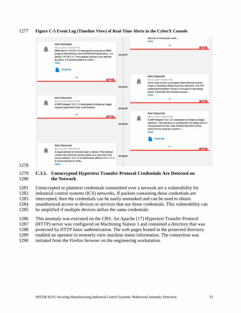
NISTIR 8219: Securing Manufacturing Industrial Control Systems: Behavioral Anomaly Detection 53
Figure C-5 Event Log (Timeline View) of Real-Time Alerts in the CyberX Console 1277
1278
C.3.1. Unencrypted Hypertext Transfer Protocol Credentials Are Detected on 1279
the Network 1280
Unencrypted or plaintext credentials transmitted over a network are a vulnerability for 1281
industrial control systems (ICS) networks. If packets containing these credentials are 1282
intercepted, then the credentials can be easily unmasked and can be used to obtain 1283
unauthorized access to devices or services that use those credentials. This vulnerability can 1284
be amplified if multiple devices utilize the same credentials. 1285
This anomaly was executed on the CRS. An Apache [17] Hypertext Transfer Protocol 1286
(HTTP) server was configured on Machining Station 1 and contained a directory that was 1287
protected by HTTP basic authentication. The web pages hosted in the protected directory 1288
enabled an operator to remotely view machine status information. The connection was 1289
initiated from the Firefox browser on the engineering workstation. 1290

NISTIR 8219: Securing Manufacturing Industrial Control Systems: Behavioral Anomaly Detection 54
1291
C.3.2. Unauthorized Secure Shell Session Is Established with an Internet-Based Server 1292
A Secure Shell (SSH) session is an encrypted and secure connection for remotely sending 1293
commands over a network. However, unauthorized SSH sessions with internet-based servers 1294
could indicate malicious activity. Attackers can use an SSH session to gain access to the ICS 1295
device and network. 1296
This anomaly was executed on the PCS. The OpenSSH [21] suite was installed and 1297
configured on a server with an internally routed public IP address (129.6.1.2). The 1298
open-source SSH client PuTTY [12] was used to establish a connection with the SSH service 1299
from the engineering workstation to the internet-based server. 1300
1301
C.3.3. Data Exfiltration to the Internet via DNS Tunneling 1302
Attacks against ICS, with the goal of information gathering, must (at some point) attempt to 1303
exfiltrate sensitive or proprietary data from the ICS network, potentially utilizing the internet 1304
as a transport mechanism. Monitoring for ICS devices communicating to other devices over 1305
the internet can help detect data exfiltration events, especially if the affected device does not 1306
normally communicate over the internet. 1307
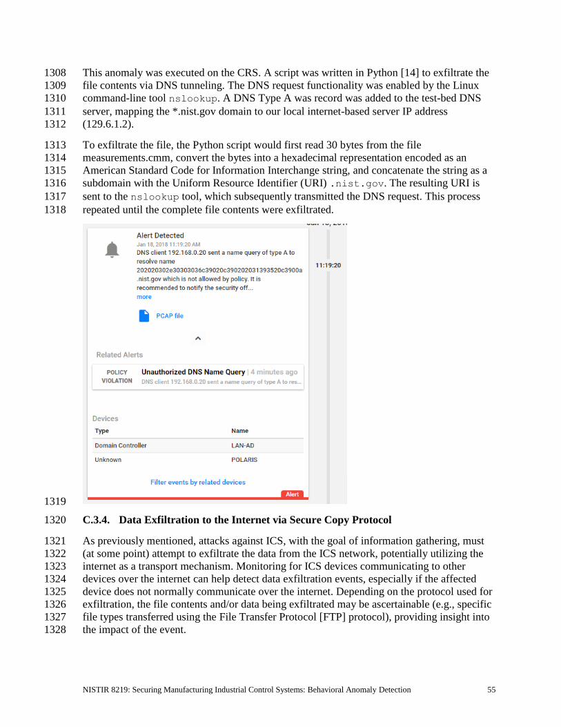
NISTIR 8219: Securing Manufacturing Industrial Control Systems: Behavioral Anomaly Detection 55
This anomaly was executed on the CRS. A script was written in Python [14] to exfiltrate the 1308
file contents via DNS tunneling. The DNS request functionality was enabled by the Linux 1309
command-line tool nslookup. A DNS Type A was record was added to the test-bed DNS 1310
server, mapping the *.nist.gov domain to our local internet-based server IP address 1311
(129.6.1.2). 1312
To exfiltrate the file, the Python script would first read 30 bytes from the file 1313
measurements.cmm, convert the bytes into a hexadecimal representation encoded as an 1314
American Standard Code for Information Interchange string, and concatenate the string as a 1315
subdomain with the Uniform Resource Identifier (URI) .nist.gov. The resulting URI is 1316
sent to the nslookup tool, which subsequently transmitted the DNS request. This process 1317
repeated until the complete file contents were exfiltrated. 1318
1319
C.3.4. Data Exfiltration to the Internet via Secure Copy Protocol 1320
As previously mentioned, attacks against ICS, with the goal of information gathering, must 1321
(at some point) attempt to exfiltrate the data from the ICS network, potentially utilizing the 1322
internet as a transport mechanism. Monitoring for ICS devices communicating to other 1323
devices over the internet can help detect data exfiltration events, especially if the affected 1324
device does not normally communicate over the internet. Depending on the protocol used for 1325
exfiltration, the file contents and/or data being exfiltrated may be ascertainable (e.g., specific 1326
file types transferred using the File Transfer Protocol [FTP] protocol), providing insight into 1327
the impact of the event. 1328

NISTIR 8219: Securing Manufacturing Industrial Control Systems: Behavioral Anomaly Detection 56
This anomaly was executed on the CRS. The OpenSSH [21] suite was installed and 1329
configured on a server with an internally routed public IP address (129.6.1.2). The secure 1330
copy protocol was then used to transfer a sensitive file over SSH from the engineering 1331
workstation to the internet. 1332
1333
C.3.5. European Institute for Computer Antivirus Research Virus Test File Is 1334
Detected on the Network 1335
Malware and computer viruses are serious threats to ICS. Malware can undermine ICS 1336
security, confidentiality, and stability, with the potential to sabotage the ICS. Providing the 1337
ability to detect the presence of viruses and malware in the ICS network is important for 1338
minimizing risk to the manufacturing system. 1339
This anomaly was executed on the PCS. The European Institute for Computer Antivirus 1340
Research (EICAR) virus test file was transferred from the human-machine interface (HMI) 1341
server to the object linking and embedding for process control (OPC) server by using 1342
Windows File Sharing (Server Message Block protocol). 1343

NISTIR 8219: Securing Manufacturing Industrial Control Systems: Behavioral Anomaly Detection 57
1344
C.3.6. Unauthorized Device Is Connected to the Network 1345
It is important to identify all devices on the ICS network, for a complete risk analysis and for 1346
minimizing potential attack vectors. The detection of unauthorized devices attached to the 1347
ICS network may indicate anomalous activity. These unauthorized devices are important to 1348
find and remove, especially because the purpose of an unauthorized device is unknown and 1349
may be malicious. 1350
This anomaly was executed on the PCS. The engineering laptop (Windows 7 operating 1351
system) was removed from the network during the baseline analysis phase of the product and 1352
was later connected to Virtual Local Area Network (VLAN)-2 to execute the anomaly. After 1353
the initial connection, background traffic was automatically generated onto the network by 1354
the laptop. 1355
1356
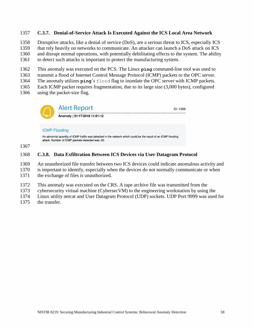
NISTIR 8219: Securing Manufacturing Industrial Control Systems: Behavioral Anomaly Detection 58
C.3.7. Denial-of-Service Attack Is Executed Against the ICS Local Area Network 1357
Disruptive attacks, like a denial of service (DoS), are a serious threat to ICS, especially ICS 1358
that rely heavily on networks to communicate. An attacker can launch a DoS attack on ICS 1359
and disrupt normal operations, with potentially debilitating effects to the system. The ability 1360
to detect such attacks is important to protect the manufacturing system. 1361
This anomaly was executed on the PCS. The Linux ping command-line tool was used to 1362
transmit a flood of Internet Control Message Protocol (ICMP) packets to the OPC server. 1363
The anomaly utilizes ping’s flood flag to inundate the OPC server with ICMP packets. 1364
Each ICMP packet requires fragmentation, due to its large size (3,000 bytes), configured 1365
using the packet-size flag. 1366
1367
C.3.8. Data Exfiltration Between ICS Devices via User Datagram Protocol 1368
An unauthorized file transfer between two ICS devices could indicate anomalous activity and 1369
is important to identify, especially when the devices do not normally communicate or when 1370
the exchange of files is unauthorized. 1371
This anomaly was executed on the CRS. A tape archive file was transmitted from the 1372
cybersecurity virtual machine (CybersecVM) to the engineering workstation by using the 1373
Linux utility netcat and User Datagram Protocol (UDP) sockets. UDP Port 9999 was used for 1374
the transfer. 1375

NISTIR 8219: Securing Manufacturing Industrial Control Systems: Behavioral Anomaly Detection 59
1376
C.3.9. Invalid Credentials Are Used to Access a Networking Device 1377
Authentication systems that are not rate-restricted may be vulnerable to password-guessing 1378
attacks, especially if the default credentials of the device have not been changed. Compiled 1379
lists containing default user credentials are freely available on the internet, as are lists of 1380
commonly used usernames and passwords. Given enough time, an attacker may be able to 1381
access vulnerable systems by using a brute-force password attack. 1382
This anomaly was executed on the PCS. The Allen-Bradley software Studio 5000 was used 1383
to download the logic from the PCS programmable logic controller (PLC) to the engineering 1384
workstation. Physical access to the PLC was required in order to change the operation mode 1385
from RUN to REMOTE RUN. 1386

NISTIR 8219: Securing Manufacturing Industrial Control Systems: Behavioral Anomaly Detection 60
1387
C.3.10. Brute-Force Password Attack Against a Networking Device 1388
As previously mentioned, authentication systems that are not rate-restricted may be 1389
vulnerable to password-guessing attacks, especially if the default credentials of the device 1390
have not been changed. Compiled lists containing default user credentials are freely available 1391
on the internet, as are lists of commonly used usernames and passwords. Given enough time, 1392
an attacker may be able to access vulnerable systems by using a brute-force password attack. 1393
This anomaly was executed on the PCS. The software Nmap [16] was used to generate the 1394
brute-force password attack by using the script telnet-brute. The attack was pointed at 1395
the PCS router, which has a Telnet service for remote configuration and is protected by a 1396
password. The service was not configured to limit the number of authentication attempts. 1397

NISTIR 8219: Securing Manufacturing Industrial Control Systems: Behavioral Anomaly Detection 61
1398
C.3.11. Unauthorized PLC Logic Download 1399
Many ICS devices provide services to remotely update control logic over the network. These 1400
network services can also provide a mechanism for attackers to replace valid control logic 1401
with malicious logic if the device is not protected. 1402
This anomaly was executed on the PCS. The Allen-Bradley software Studio 5000 was used 1403
to download the logic from the PCS PLC to the engineering workstation. Physical access to 1404
the PLC was required in order to change the operation mode from RUN to REMOTE RUN. 1405
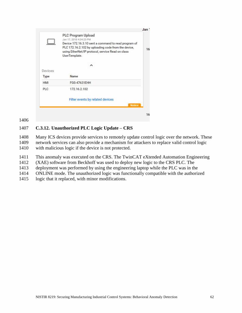
NISTIR 8219: Securing Manufacturing Industrial Control Systems: Behavioral Anomaly Detection 62
1406
C.3.12. Unauthorized PLC Logic Update – CRS 1407
Many ICS devices provide services to remotely update control logic over the network. These 1408
network services can also provide a mechanism for attackers to replace valid control logic 1409
with malicious logic if the device is not protected. 1410
This anomaly was executed on the CRS. The TwinCAT eXtended Automation Engineering 1411
(XAE) software from Beckhoff was used to deploy new logic to the CRS PLC. The 1412
deployment was performed by using the engineering laptop while the PLC was in the 1413
ONLINE mode. The unauthorized logic was functionally compatible with the authorized 1414
logic that it replaced, with minor modifications. 1415

NISTIR 8219: Securing Manufacturing Industrial Control Systems: Behavioral Anomaly Detection 63
1416
C.3.13. Unauthorized PLC Logic Update – PCS 1417
As previously mentioned, many ICS devices provide services to remotely update control 1418
logic over the network. These network services can also provide a mechanism for attackers to 1419
replace valid control logic with malicious software if the device is not protected. 1420
This anomaly was executed on the PCS. The Allen-Bradley software Studio 5000 was used 1421
to upload new logic from the engineering workstation to the PCS PLC. Physical access to the 1422
PLC was required in order to change the operation mode from RUN to REMOTE RUN. 1423

NISTIR 8219: Securing Manufacturing Industrial Control Systems: Behavioral Anomaly Detection 64
1424
C.3.14. Undefined Modbus Transmission Control Protocol Function Codes Are 1425
Transmitted to the PLC 1426
Communications that do not conform to the defined specifications of the industrial protocol 1427
may cause an ICS device to act in an undefined or unsafe manner. Depending on the 1428
manufacturing process and the ICS device, the nonconforming communications may or may 1429
not be impactful, but investigation into the cause is warranted. 1430
This anomaly was executed on the CRS. Python [14] was used to create a Modbus 1431
Transmission Control Protocol (TCP) message with the undefined function code value of 49 1432
(0x31). The message was generated by the CybersecVM and was transmitted to the PLC 1433
Modbus server. 1434

NISTIR 8219: Securing Manufacturing Industrial Control Systems: Behavioral Anomaly Detection 65
1435
C.3.15. Unauthorized Ethernet/IP Scan of the Network 1436
During the reconnaissance phase, an attacker may attempt to locate vulnerable services in an 1437
ICS network and will likely include probing for ICS-specific services (e.g., Ethernet/IP). 1438
Once a vulnerable service, host, or device is discovered, an attacker may attempt to exploit 1439
that entity. 1440
This anomaly was executed on the PCS. The software Nmap [16] was used to perform a port 1441
scan (Ports 1 through 1024) against two hosts: the HMI and the plant controller. The scan 1442
originated from the CybersecVM, logically located in the test-bed local area network (LAN). 1443
This anomaly was executed on the PCS. The software Nmap [16] was used to perform an 1444
Ethernet/IP device scan by using the script enip-info. The scan was pointed at the PCS 1445
subnet 172.16.2.100/28 and was executed by the CybersecVM in the test-bed LAN. 1446

NISTIR 8219: Securing Manufacturing Industrial Control Systems: Behavioral Anomaly Detection 66
1447

NISTIR 8219: Securing Manufacturing Industrial Control Systems: Behavioral Anomaly Detection 67
Appendix D. OSIsoft Process Information Supplemental Information 1448
The OSIsoft Process Information (PI) System is a suite of software applications for 1449
capturing, analyzing, and storing real-time data for industrial processes. Although the PI 1450
System is typically utilized as a process historian, the PI System is also utilized to collect, 1451
store, and manage data in real time. Interface nodes retrieve data from disparate sources to 1452
the PI Server, where the PI Data Archive resides. Data is stored in the Data Archive and is 1453
accessible in the assets defined in the Asset Framework (AF). Data is then typically accessed, 1454
either directly from the Data Archive or from the AF Server, by using tools in the PI 1455
visualization suite. Typically, most PI System users consume data by accessing the AF 1456
Server, rather than directly accessing the Data Archive. This build demonstrates how PI can 1457
be leveraged to monitor for specific behavioral anomalies of the process that may be caused 1458
by cybersecurity incidents, and to alert operators and cybersecurity personnel of the 1459
anomalies. 1460
D.1. Build Architecture 1461
The PI System was installed in a virtual environment (HyperV) that already existed within 1462
the collaborative robotic system (CRS). The virtual machine (VM) for the PI System used 1463
Windows Server 2008 R2 as the operating system, with four virtual central-processing-unit 1464
cores and 16 gigabytes (GB) of random-access memory. The VM was networked directly 1465
into the existing network topology of the CRS with a dedicated Internet Protocol (IP) address 1466
(192.168.0.21). 1467
D.2. Installation and Configuration 1468
Compared with the other three installations, the PI System was installed locally on existing 1469
virtualization hardware. Remote assistance and troubleshooting were provided by OSIsoft for 1470
the installation and configuration of the system within the CRS. 1471
Six components were installed in the VM: 1472
• PI AF 1473
• PI Data Archive 1474
• PI Process Explorer 1475
• PI Vision 1476
• PI Modbus Ethernet Interface 1477
• Structured Query Language Server 2012 1478
Four additional hard-drive partitions (virtual) were created to support the PI System 1479
installation: 1480
• PI Server (E:): 60 GB 1481
• archives (F:): 60 GB 1482
• queues (G:): 30 GB 1483
• backups (H:): 21 GB 1484

NISTIR 8219: Securing Manufacturing Industrial Control Systems: Behavioral Anomaly Detection 68
D.2.1. PI AF Installation 1485
1. Run PI-AF-Services_2017-R2-Update-1_Demo.exe to launch the installer. 1486
2. Select the Server Role Features shown in Figure D-1. Ensure that the Installation 1487
Directory is set to the corresponding drive letter labeled as PI Server. Click Next. 1488
Figure D-1 Server Role Features to Be Selected During PI AF Installation 1489
1490
3. Keep the default settings. Click Next. 1491
4. Set the Directory Name to <Configure Later>. Click Next. 1492
5. Leave the Service Account as default. Click Next. 1493
6. Upon completed installation, reboot the server. 1494
D.2.2. PI Data Archive Installation 1495
1. Run the PI-Data-Archive_2017_R2A_Demo_.exe file. 1496
2. When prompted for the License File, browse to the location of the pilicense.dat file 1497
from OSIsoft. Click Next. 1498
3. Specify a name for the Default Asset server, or leave it as the default host name. 1499
Click Next. 1500

NISTIR 8219: Securing Manufacturing Industrial Control Systems: Behavioral Anomaly Detection 69
4. Select the Installation Directory for the Data Archive. Click Next. 1501
5. Set the remaining directories as shown in Figure D-2, corresponding to the correct 1502
drive letters. Click Next. 1503
6. Click Next, and verify that the service status shows as Running. Click Next to finish 1504
the installation and to reboot the server. 1505
Figure D-2 Data Directories to Be Selected During PI Data Archive Installation 1506
1507
D.2.3. PI System Process Explorer Installation 1508
1. Run the PIProcessBook_2015_R2_SP1_06-Jun-2018.exe file to start the installation. 1509
2. A screen titled OSIsoft Setup Progress will begin, installing the different required 1510
components. 1511
3. A dialog box will appear once the installation is complete. 1512
D.2.4. PI Vision Installation 1513
1. Run the PI-Vision_2017-R2-Update-1-90-Day-Trial_.exe file to start the installation. 1514
2. Select the Operating Configuration Store. In this build, the Asset Server was called 1515
PI-ROBOTICS. Click Connect, and then click Next. 1516
3. Verify that the PI Web API port is 443. Click Next. 1517
4. On the Submit URL page, do not change the automatically generated Indexed 1518
Search Crawler Submit URL. In this build, the automatically generated Uniform 1519
Resource Locator (URL) was https://pi-robotics.lan.lab/piwebapi/. Click Next. 1520
5. Review the changes. Click Next. 1521

NISTIR 8219: Securing Manufacturing Industrial Control Systems: Behavioral Anomaly Detection 70
6. When the installation has completed, review the Confirmation page for errors. If no 1522
errors are found, then click Finish. 1523
7. The installer will continue installing additional components. Click Continue when 1524
prompted to install Windows features. 1525
8. If prompted, leave the default installation directories. Click Next. 1526
9. Once the installation finishes, click Finish. 1527
D.2.5. PI System Modbus Ethernet Interface Installation 1528
1. Run the ModbusE_ReadWrite_4.2.2.31_DEMO.exe file to start the installation. 1529
2. Keep all default settings, and complete the installation. 1530
3. Open PI Interface Configuration Utility, and select the interface PIModbusE1. 1531
4. Configure the Display Name. In this build, the default name was kept. 1532
5. Select the option Service in the left navigation panel. 1533
6. Select the Startup Type option Auto, click Create, and then click Apply. 1534
7. Click the Start Service ( ) button on the top navigation bar. 1535
8. If the service is running properly, then the label Running will appear on the status bar 1536
at the bottom of the dialog. 1537
D.2.6. PI System Points and Assets Configuration 1538
PI System points utilizing the ModbusE interface were manually created using the PI System 1539
Management Tools (SMT) software. Modbus device addresses, register names, and register 1540
addresses were known prior to configuring the points. 1541
1. Launch the PI SMT by navigating to Start > All Programs > PI System > PI 1542
System Management Tools. 1543
2. Select Points > Points Builder from the left navigation pane. 1544
3. Create a new tag, and enter the required attributes (shown in Figure D-3). An example 1545
of the configuration for the Point PLC-ExperimentMode is shown in Figure D-4. 1546
4. Click Save. 1547

NISTIR 8219: Securing Manufacturing Industrial Control Systems: Behavioral Anomaly Detection 71
Figure D-3 Configuration Options in the PI Point Builder for Tags Utilizing the ModbusE 1548 Interface 1549
1550
Figure D-4 Example Configuration Settings for the Tag PLC-ExperimentMode 1551
1552
In Figure D-4, the fields Location1 through Location5 have different uses, depending on the 1553
interface used, and are described in detail in Figure D-3. The Instrument Tag field describes 1554
the IP address of the Modbus Transmission Control Protocol (TCP) server that the ModbusE 1555
interface needs to poll. 1556
The PI System AF and System Explorer were used to define a hierarchical structure for the 1557
PI System points, to display tag values for each asset, and to provide an interface for viewing 1558
and acknowledging alerts. Because of the relatively simple interactions among elements of 1559
the CRS, the structure created in the AF contained the supervisory programmable logic 1560
controller (PLC) as the top-level element, and Station 1 through Station 4 as child elements. 1561

NISTIR 8219: Securing Manufacturing Industrial Control Systems: Behavioral Anomaly Detection 72
Asset templates were created for the PLC and four machining stations to automatically link 1562
to the proper PI System points based on the asset. The final configuration of assets is shown 1563
in Figure D-5, showing the hierarchical structure of Workcell 1 > PLC > Station 1. Also 1564
shown in this figure are the Attributes for Station 1, as received from the PI System points. 1565
Figure D-5 PI System Explorer View Showing the Configured Assets (Elements), the Resulting 1566 Hierarchical Structure of Assets, and Live Attributes Received from Station 1 1567
1568
For both the PLC and machining-station asset templates, analysis functions were created to 1569
generate alerts for the operator when identified anomalous events are detected. The 1570
anomalous events to be detected are the anomalies described in Section D.3. The analysis 1571
functions are described in Sections D.2.7 and D.2.8. Respective event-frame generators for 1572
each analysis function were created to generate the actual alerts. 1573
D.2.7. PLC Asset Template Analysis Functions 1574
The analysis functions provided in the following subsections were created to generate alerts 1575
in the PLC asset template when their respective anomalous events are detected. For the sake 1576
of brevity, the event-frame generation code is not shown. In general, the typical event-frame 1577
generator contains logic to activate the event frame when the analysis function result is TRUE, 1578
and to stop the event frame after the analysis function result is FALSE or after a related 1579
element variable changes to a value indicating that the failure or fault has been resolved. 1580
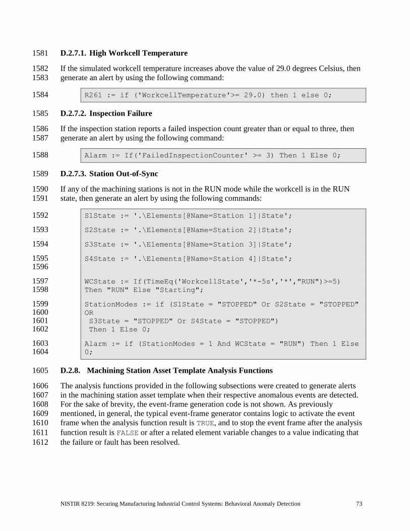
NISTIR 8219: Securing Manufacturing Industrial Control Systems: Behavioral Anomaly Detection 73
D.2.7.1. High Workcell Temperature 1581
If the simulated workcell temperature increases above the value of 29.0 degrees Celsius, then 1582
generate an alert by using the following command: 1583
R261 := if ('WorkcellTemperature'>= 29.0) then 1 else 0; 1584
D.2.7.2. Inspection Failure 1585
If the inspection station reports a failed inspection count greater than or equal to three, then 1586
generate an alert by using the following command: 1587
Alarm := If('FailedInspectionCounter' >= 3) Then 1 Else 0; 1588
D.2.7.3. Station Out-of-Sync 1589
If any of the machining stations is not in the RUN mode while the workcell is in the RUN 1590
state, then generate an alert by using the following commands: 1591
S1State := '.\Elements[@Name=Station 1]|State'; 1592
S2State := '.\Elements[@Name=Station 2]|State'; 1593
S3State := '.\Elements[@Name=Station 3]|State'; 1594
S4State := '.\Elements[@Name=Station 4]|State'; 1595 1596
WCState := If(TimeEq('WorkcellState','*-5s','*',"RUN")>=5) 1597 Then "RUN" Else "Starting"; 1598
StationModes := if (S1State = "STOPPED" Or S2State = "STOPPED" 1599 OR 1600 S3State = "STOPPED" Or S4State = "STOPPED") 1601 Then 1 Else 0; 1602
Alarm := if (StationModes = 1 And WCState = "RUN") Then 1 Else 1603 0; 1604
D.2.8. Machining Station Asset Template Analysis Functions 1605
The analysis functions provided in the following subsections were created to generate alerts 1606
in the machining station asset template when their respective anomalous events are detected. 1607
For the sake of brevity, the event-frame generation code is not shown. As previously 1608
mentioned, in general, the typical event-frame generator contains logic to activate the event 1609
frame when the analysis function result is TRUE, and to stop the event frame after the analysis 1610
function result is FALSE or after a related element variable changes to a value indicating that 1611
the failure or fault has been resolved. 1612

NISTIR 8219: Securing Manufacturing Industrial Control Systems: Behavioral Anomaly Detection 74
D.2.8.1. High Trouble Call Count 1613
Two analysis functions were created for this alert. First, determine if the machining station is 1614
in the TROUBLE state by using the following command: 1615
Trouble := if ('State' = "TROUBLE" AND ((PrevVal('State','*-1616 1s') = "TROUBLE") = False)) THEN "TROUBLE" ELSE NoOutput(); 1617
If the machining station has entered the TROUBLE state, then count this event. If the number 1618
of times that the machining station has entered the TROUBLE state in the previous 1619
10 minutes is greater than or equal to five, then generate an alert by using the following 1620
command: 1621
TroubleCount := If (EventCount('Alarm-TroubleCounterEvent','*-1622 10m','*') >= 5) Then 1 Else 0; 1623
Variable1 := 'State'; 1624
D.2.8.2. Robot Proximity Fault 1625
If the machining station is in the RUN mode and a robot proximity message has not been 1626
received within the previous two minutes, then generate an alert by using the following 1627
command: 1628
Alarm := If (('Mode' = "RUN") And (PrevVal('Mode','*-2m') = 1629 "RUN") And (TagMax(';RobotProximity','*-2m','*') = 0)) then 1 1630 else 0; 1631
D.2.8.3. Station Door Fault 1632
If the machining station is in the ACTIVE state and the door is not closed, then generate an 1633
alert by using the following command: 1634
Door_Open_Alarm := if (TimeEq('State','*-2s','*',"ACTIVE")>=2 1635 And TimeEq('Door State','*-2s','*',"CLOSED")<1) Then 1 ELSE 0; 1636
Variable1 := TimeEq('Door State','*-2s','*',"CLOSED"); 1637
D.2.8.4. Station Mode Error 1638
If the register value for the machining station mode (as written by the PLC) is not within the 1639
valid range of values (0 to 1), then generate an alert by using the following command: 1640
Alarm := If('RawMode' < 0 OR 'RawMode' > 1) Then 1 Else 0; 1641

NISTIR 8219: Securing Manufacturing Industrial Control Systems: Behavioral Anomaly Detection 75
D.2.8.5. Station State Error 1642
If the register value for the machining station state (as reported by the machining station) is 1643
not within the valid range of values (0 to 5), then generate an alert by using the following 1644
command: 1645
Alarm := If('RawState' < 0 OR 'RawState' > 5) Then 1 Else 0; 1646
D.2.9. Viewing and Acknowledging Alerts 1647
The PI System Explorer was used to view and acknowledge alerts (event frames) generated 1648
by the analyses templates. An example of the alerts is shown in Figure D-6, showing all of 1649
the alerts generated by the anomalies during the execution of the anomaly scenarios. 1650
Figure D-6 PI System Explorer Interface Showing an Example of Alerts Displayed to the 1651 Operator for Acknowledgment, as Used During Anomaly Scenario Execution 1652
1653
D.3. Anomaly Scenarios 1654
The historian/sensor-based anomaly detection method was demonstrated for the scenarios 1655
detailed in the following subsections. Each scenario includes a description of the anomaly, a 1656
detailed description of how each demonstration event was conducted in the Cybersecurity for 1657
Smart Manufacturing Systems environment, and the observed results. 1658
The anomalies listed below demonstrate the fusion of cybersecurity and manufacturing 1659
activities into a cohesive operation for detecting operational/maintenance issues and for 1660
potentially identifying issues caused by cybersecurity incidents. In-depth knowledge of the 1661
manufacturing system enables engineers to design PI System analysis functions to monitor 1662
and alert when anomalous events occur, and to track trends of anomalies over extended 1663
periods of time. With proper communication between operators and cybersecurity personnel, 1664
anomalous manufacturing process events can be analyzed to determine if they could have 1665
been caused by a cybersecurity incident and could have been mitigated. 1666

NISTIR 8219: Securing Manufacturing Industrial Control Systems: Behavioral Anomaly Detection 76
D.3.1. Frequency Increase of Trouble Calls from a Machining Station 1667
Trouble calls are automatically generated by a machining station when it detects an anomaly 1668
during manufacturing operations (e.g., broken tooling, coolant failure). 1669
This anomaly was executed on the CRS. The machining station logic for Station 2 contained 1670
a register that enabled trouble calls to be initiated on demand, generating the anomaly. This 1671
register was set using a menu option on the human-machine interface (HMI). When enabled, 1672
the machining station would enter the TROUBLE state after each part was placed in the 1673
machine, and would be automatically cleared after eight seconds had elapsed. 1674
1675
D.3.2. Machining Station Shuts Down During Normal Workcell Operations 1676
The workcell requires that all four machining stations are operational and in the RUN mode 1677
while the workcell is in the RUN state. 1678
This anomaly was executed on the CRS. The machining station logic for Station 2 contained 1679
a register that enabled a “forced shutdown” to be initiated, generating the anomaly. This 1680
register was set using a menu option on the HMI. When enabled, the machining station 1681
would enter the STOP mode while the rest of the workcell machines were operational. 1682
1683
D.3.3. Inspection Station Rejects All Parts Leaving the Workcell 1684
The quantity of good and bad parts exiting the inspection station is counted by the 1685
supervisory PLC. An increase in the number of rejected parts indicates that the workcell 1686
should be inspected by an operator to determine the cause. 1687
This anomaly was executed on the CRS. The station logic for Station 4 contained a register 1688
that enabled the “inspection failure of all parts” anomaly. This register was set using a menu 1689
option on the HMI. When enabled, the inspection station would report a failed result for 1690
every inspection performed until the anomaly was disabled. 1691
1692

NISTIR 8219: Securing Manufacturing Industrial Control Systems: Behavioral Anomaly Detection 77
D.3.4. Machining Station Door Sensor Fails 1693
The unsafe condition that this sensor failure can cause warrants investigation by an operator. 1694
Substantial damage can occur to both the machining station and robots if this sensor failure is 1695
not detected. This anomaly could be a goal for an attacker who has the intent to cause 1696
production disruption or financial loss through equipment damage. 1697
This anomaly was executed on the CRS. The machining station has a simulated door that 1698
must open and close to allow the robot to have access into the machine for placing raw 1699
material and removing finished parts. The machining station logic for Station 2 contained a 1700
register that enabled the door-sensor failure anomaly. This register was set using a menu 1701
option on the HMI. When enabled, the failure of this sensor caused the machining station to 1702
report that the door was always “OPEN.” 1703
1704
D.3.5. Abnormal Process Variable Data Is Transmitted to the PLC 1705
Two-way communication occurs between the supervisory PLC and the machining station 1706
during normal operations. If a process variable trends outside the known operational range, 1707
then this anomaly should be reported. 1708
This anomaly was executed on the CRS. Each machining station contains a Modbus TCP 1709
server for communicating operational information to, and receiving commands from, the 1710
supervisory PLC. The machining station logic for Station 2 contained a register that enabled 1711
specific operational information to be corrupted before it was transmitted to the PLC. This 1712
register was set using a menu option on the HMI. 1713
1714
D.3.6. Abnormal Process Variable Data Is Transmitted to a Machining Station 1715
As previously mentioned, two-way communication occurs between the supervisory PLC and 1716
the machining station during normal operations. If a process variable trends outside the 1717
known operational range, then this anomaly should be reported. 1718
This anomaly was executed on the CRS. The supervisory PLC contains a Modbus TCP client 1719
for communicating commands to, and receiving operational information from, the machining 1720
stations. The supervisory PLC contained a register that enabled specific commands to be 1721
corrupted before they were transmitted to the machining stations. This register was set using 1722
a menu option on the HMI. 1723
1724

NISTIR 8219: Securing Manufacturing Industrial Control Systems: Behavioral Anomaly Detection 78
D.3.7. Robots Fail to Send Required Sensor Data to a Machining Station 1725
As previously mentioned, the unsafe condition that this sensor failure can cause warrants 1726
investigation by an operator. Substantial damage can occur to both the machining station and 1727
robots if this sensor failure is not detected. This anomaly could be a goal for an attacker who 1728
intends to cause production disruption or financial loss through equipment damage. 1729
This anomaly was executed on the CRS. The machining station has a simulated door that 1730
must open and close to allow the robot access into the machine for placing raw material and 1731
removing finished parts. The two robots report their locations (via Modbus TCP) to the 1732
machining stations so that they do not attempt to close the door while the robot is still 1733
operating within the machine. Robot Controller 1 contains a configuration option to disable 1734
this reporting, resulting in Stations 1 and 2 not receiving robot location information. This 1735
configuration option was used to generate the anomaly. 1736
1737
D.3.8. Workcell Temperature Increases Above a Specified Threshold 1738
Process variables that impact the output quality of the workcell must be monitored for 1739
deviation from expected values. The temperature of the workcell increases during normal 1740
operations and must be properly cooled to maintain quality; therefore, the workcell 1741
temperature is monitored. 1742
This anomaly was executed on the CRS. The workcell contained a simulated temperature 1743
sensor, which was used to “monitor” the temperature within the workcell. The temperature 1744
was then displayed to the operator, on the HMI. The workcell temperature would increase to 1745
an expected value while the workcell was operational and would decrease to room 1746
temperature when the system was shut down. During anomalous conditions, the temperature 1747
would increase beyond a threshold, causing all parts produced during that period to be 1748
scrapped. 1749
The temperature sensor was simulated by the PLC. The anomalous temperature increase was 1750
enabled by a register within the PLC and was set using a menu option on the HMI. 1751
1752

NISTIR 8219: Securing Manufacturing Industrial Control Systems: Behavioral Anomaly Detection 79
Appendix E. Acronyms and Abbreviations 1753
24/7 24 Hours a Day, Seven Days a Week
AF Asset Framework
BAD Behavioral Anomaly Detection
CPU Central Processing Unit
CRS Collaborative Robotic System
CSMS Cybersecurity for Smart Manufacturing Systems
CSV Comma-Separated Values
CybersecVM Cybersecurity Virtual Machine
DA Data Access
DCOM Distributed Component Object Model
DMZ Demilitarized Zone
DNS Domain Name System
DoS Denial of Service
EICAR European Institute for Computer Antivirus Research
EL Engineering Laboratory
FTP File Transfer Protocol
GB Gigabyte(s)
GUI Graphical User Interface
HMI Human-Machine Interface
HTTP Hypertext Transfer Protocol
ICMP Internet Control Message Protocol
ICS Industrial Control System
ID Identifier
IDS Intrusion Detection System
IP Internet Protocol
IPC Industrial Personal Computer
IT Information Technology
LAN Local Area Network
NISTIR 8219: Securing Manufacturing Industrial Control Systems: Behavioral Anomaly Detection 80
LTS Long-Term Support
M Megabyte(s)
MAC Media Access Control
NCCoE National Cybersecurity Center of Excellence
NIC Network Interface Card
NIST National Institute of Standards and Technology
NISTIR National Institute of Standards and Technology Interagency Report
NTP Network Time Protocol
OPC Object Linking and Embedding for Process Control
OS Operating System
OT Operational Technology
PCS Process Control System
PDF Portable Document File
PHP Hypertext Preprocessor
PI Process Information
PLC Programmable Logic Controller
ROS Robot Operating System
SCADA Supervisory Control and Data Acquisition
SIEM Security Information and Event Management
SMT System Management Tools
SNTP Simple Network Time Protocol
SP Special Publication
SPAN Switch Port Analyzer
SSH Secure Shell
TCP Transmission Control Protocol
TE Tennessee Eastman
UDP User Datagram Protocol
URI Uniform Resource Identifier
URL Uniform Resource Locator

NISTIR 8219: Securing Manufacturing Industrial Control Systems: Behavioral Anomaly Detection 81
USB Universal Serial Bus
VLAN Virtual Local Area Network
VM Virtual Machine
XAE eXtended Automation Engineering
XLSX Microsoft Excel Workbook File
NISTIR 8219: Securing Manufacturing Industrial Control Systems: Behavioral Anomaly Detection 82
Appendix F. References 1754
[1] “Framework for improving critical infrastructure cybersecurity,” NIST, Gaithersburg, 1755
MD, Apr. 16, 2018 [Online]. Available: 1756
https://www.nist.gov/publications/framework-improving-critical-infrastructure-1757
cybersecurity-version-11. 1758
[2] K. Stouffer et al., “Cybersecurity framework manufacturing profile,” NIST, 1759
Gaithersburg, MD, NISTIR 8183, 2017 [Online]. Available: 1760
https://www.nist.gov/publications/cybersecurity-framework-manufacturing-profile. 1761
[3] K. Stouffer et al., “Guide to industrial control systems (ICS) security,” NIST, 1762
Gaithersburg, MD, SP 800-82 Revision 2, May 2015 [Online]. Available: 1763
https://www.nist.gov/publications/guide-industrial-control-systems-ics-security. 1764
[4] Security for Industrial Automation and Control Systems: Establishing an Industrial 1765
Automation and Control Systems Security Program, ANSI/ISA Standard 62443-2-1, 1766
2009. 1767
[5] Security for Industrial Automation and Control Systems – Part 2-3: Patch 1768
Management in the IACS Environment, ANSI/ISA Standard 62443-2-3, 2015. 1769
[6] Joint Task Force Transformation Initiative, “Security and privacy controls for federal 1770
information systems and organizations,” NIST, Gaithersburg, MD, SP 800-53 1771
Revision 4, Apr. 2013. 1772
[7] R. Candell, T. Zimmerman, and K. Stouffer, “An industrial control system 1773
cybersecurity performance testbed,” NIST, Gaithersburg, MD, NISTIR 8089, Nov. 1774
2015 [Online]. Available: https://www.nist.gov/publications/industrial-control-1775
system-cybersecurity-performance-testbed. 1776
[8] T. Zimmerman, “Metrics and key performance indicators for robotic cybersecurity 1777
performance analysis,” NIST, Gaithersburg, MD, NISTIR 8177, Apr. 2017 [Online]. 1778
Available: https://www.nist.gov/publications/metrics-and-key-performance-1779
indicators-robotic-cybersecurity-performance-analysis. 1780
[9] C. Tang, “Key performance indicators for process control system cybersecurity 1781
performance analysis,” NIST, Gaithersburg, MD, NISTIR 8188, Aug. 2017 [Online]. 1782
Available: https://www.nist.gov/publications/key-performance-indicators-process-1783
control-system-cybersecurity-performance-analysis. 1784
[10] J. J. Downs and E. F. Vogel, “A plant-wide industrial process control problem,” 1785
Comput. Chem. Eng., vol. 17, no. 3, pp. 245-255, 1993. 1786
[11] N. L. Ricker. (2015, Jan. 23). Tennessee Eastman challenge archive [Online]. 1787
Available: https://depts.washington.edu/control/LARRY/TE/download.html. 1788
[12] S. Tatham. (1999). Download PuTTY [Online]. Available: https://www.putty.org/. 1789
[13] P. Biondi. (2008). Scapy [Online]. Available: https://scapy.net/. 1790

NISTIR 8219: Securing Manufacturing Industrial Control Systems: Behavioral Anomaly Detection 83
[14] G. van Rossum. (1990). Python [Online]. Available: https://www.python.org/. 1791
[15] T. Kosse. (2001). FileZilla [Online]. Available: https://filezilla-project.org/. 1792
[16] G. Lyon. (1997). Nmap.org [Online]. Available: https://nmap.org/. 1793
[17] R. McCool. (1995). Apache HTTP server project [Online]. Available: 1794
https://httpd.apache.org/. 1795
[18] A. Rudakov. (n.d.). File modbus-discover [Online]. Available: 1796
https://nmap.org/nsedoc/scripts/modbus-discover.html. 1797
[19] PHP Group. (2001). PHP: Hypertext preprocessor [Online]. Available: 1798
http://www.php.net/. 1799
[20] G. Woltman. (1996). Free Mersenne prime search software: Prime95 version 29.4 1800
build 7 [Online]. Available: https://www.mersenne.org/download/. 1801
[21] Wikimedia Foundation, Inc. (1999). OpenSSH [Online]. Available: 1802
https://en.wikipedia.org/wiki/OpenSSH. 1803