seeder/spreaders trailer mount - gearmore.com · seeder/spreaders trailer mount assembly,...
TRANSCRIPT

SEEDER/SPREADERSTRAILER MOUNT
Assembly, Operation, Service & Parts Manual
For Models PTP180-P & PTP300-P
March 2009
Form: PTPSprdr

TABLE OF CONTENTS
PAGE
Introduction ........................................................................................................ 1
Preparation Checklist ........................................................................................ 2
Safety Decals ....................................................................................................... 3
Safety Information ............................................................................................. 4
General Information ......................................................................................... 5
Assembly ....................................................................................................... 6 - 9
Pull Type Spreader Use ...................................................................................10
Adjusting the Spread .......................................................................................11
Spreading Chart ...................................................................................12
Adjustment ........................................................................................................13
Adjusting Spreader Vanes ..................................................................13
Features & Option ...........................................................................................14
Lubrication & Service ......................................................................................15
Replacement of Spreader Vanes .......................................................15
Operation ..........................................................................................................16
Spreading in Fields ...........................................................................................17
Parts Breakdowns .....................................................................................18 - 19
Parts Lists .....................................................................................20 - 21
Limited Warranty .............................................................................................22
We would like to thank you for purchasing a Gearmore product and we assure you that you have made a good choice, as now you have a very high quality machine. Please follow all instructions contained in this manual for a long and trustworthy machine life.
Know your controls. Read this manual and the manual provided with your tractor before operating your equipment. Keep this manual handy for ready reference. Learn how to stop the tractor engine and spreader quickly in case of an emergency. DO NOT allow adults without proper instructions or children to operate machinery. Require all operators to read this manual carefully and become acquainted with all adjustments and operating procedures before attempting to operate the equipment. Replacement manuals can be obtained from your selling dealer.
The equipment you have purchased has been carefully engineered and manufactured to provide dependable and satisfactory use. Like all mechanical products, it will require cleaning and upkeep. Lubricate the unit as specifi ed. Please observe all safety information in this manual and safety decals on the equipment.
For service, your authorized dealer has trained mechanics, genuine service parts, and the necessary tools and equipment to handle all of your service needs.
Use only genuine service parts. Substitute parts will void the warranty and may not meet standards required for safe and satisfactory operation. Record the model number and serial number of your equipment in the warranty page of this manual.
Throughout this manual, the term IMPORTANT is used to indicate that failure to observe procedures can cause damage to equipment. The terms CAUTION, WARNING and DANGER are used in conjunction with the Safety-Alert Symbol, (a triangle with an exclamation mark), to indicate the degree of hazard for items of personal safety.
This Safety-Alert Symbol indicates a hazard and means ATTENTION! BECOME ALERT! YOUR SAFETY IS INVOLVED!
DANGER Indicates an imminently hazardous situation that, if not avoided, will result in death or serious injury.
Indicates a potentially hazardous situation that, if not avoided, could WARNING result in death or serious injury, and includes hazards that are exposed when guards are removed.
CAUTION Indicates a potentially hazardous situation that, if not avoided, may result in minor or moderate injury.
IMPORTANT Indicates that failure to observe can cause damage to equipment.
NOTE Indicates helpful information.
It is IMPORTANT to read this manual carefully before
operating the spreader!
INTRODUCTION
1

PREPARATION CHECKLIST
2
THIS CHECKLIST TO REMAIN IN OWNER’S MANUALIT IS YOUR RESPONSIBILITY TO COMPLETE THE PROCEDURES LISTED
BELOW BEFORE OPERATING THE SPREADER
Preparation Check List 1. Implement is completely assembled. 2. Inspect for damage and loose or missing parts 3. All decals in place and readable. 4. All fi ttings and drive components are secure. 5. Overall condition good. 6. Check hopper for any foreign objects. 7. Operator has been instructed on the safe and proper use of the implement. 8. Lubrication - See Lubrication & Maintenance Section
The purpose of this manual is to assist you in operating and maintaining your spreader for years of service. Read it carefully. The information and instructions in this manual have been compiled from extensive fi eld experience and engineering data. Some information may be general in nature due to unknown and varying operating conditions. However, through experience and these instructions, you should be able to develop procedures suitable to your particular situation.
The illustrations and data used in this manual were current at the time of printing, but because we maintain an ongoing program of product improvement, we reserve the right to make improvements in design or changes in specifi cations without incurring any obligation to install them on units previously sold. Because of the possibility that some photographs in this manual were taken of prototype models, production models may vary in some detail.
All information, illustrations and specifi cations in this manual are based on the latest information available at the time of publication. The right is
reserved to make changes at any time without notice.
RETAIL CUSTOMER'S WARRANTY RESPONSIBILITY
It is the Retail Customer and/or Operator's responsibility to read the Operator's Manual, to operate, lubricate, maintain and store the product in accordance with all instructions and safety procedures. Failure of the operator to read the Operator's Manual is a misuse of this equipment. It is the Retail Customer and/or Operator's responsibility to inspect the product and to have any part(s) repaired or replaced when continued operation would cause damage or excessive wear to other parts or cause a safety hazard. It is the Retail Customer's responsibility to deliver the product to the authorized dealer from whom he purchased it, for service or replacement of defective parts which are covered by warranty. Repairs to be submitted for warranty consideration must be made within thirty (30) days of failure. It is the Retail Customer's responsibility for any cost incurred by the dealer for traveling to or hauling of the product for the purpose of performing a warranty obligation or inspection.

SAFETY DECALS
3
ATTENTION!
Be sure that the safety labels are readable. Clean them up using a cloth, water and soap. Replace the damaged labels placing them in the right position, as subsequently described.
The safety signs on the machine supply the most important indications; their observance helps your safeness.
1. ATTENTION! Before making any operation on the machine, stop the engine of the tractor or of the self-moving means, remove the key, put on the parking brake and read carefully the operator's manual.
2. ATTENTION! - DANGER! Possible throwing of material and/or objects, please do not stop or come up to the machine. Keep a safety distance of 50 feet, at least, from the machine.
4. ATTENTION! Use the individual Protection Devices, as required.
Where to place the safety decals on the machine
3. ATTENTION! - DANGER! Forbidden to go inside the hopper or to transport somebody with the machine.

OPERATIONAL SAFETY
It is absolutely necessary to empty the hopper before lowering the spreader to the ground.
Guards and safety shields are for your protection. DO NOT operate equipment unless they are in place.
Read and observe all safety decals on the tractor and spreader.
NEVER allow anyone, other than the operator, within 25' of machine while in operation.
DO NOT stop or start suddenly when going uphill or downhill. Avoid operation on steep slopes.
Be alert for holes in terrain and other hidden hazards. ALWAYS drive slowly over rough ground.
Reduce speed on slopes and in sharp turns to prevent tipping or loss of control. Be careful when changing directions on slopes.
Take all possible precautions when leaving tractor unattended: Shift into neutral, set parking brake, stop engine and remove key from ignition.
SAFETY INFORMATION
4

GENERAL INFORMATION
5
MACHINE INFORMATION:
The models introduced in this manual have been designed and made exclusively allowing the distribution of solid, granular fertilizers and of seeds in the fi eld.
A different use is considered improper. Any arbitrary modifi cation made to this machine relieve the manufacturer from any responsibility for damages or lesions, also serious, that can be caused to the operators, to third parties or to things.
NAME PLATE:
On the hopper of every machine a name plate is fi xed showing the model, the number of series and the year of construction of the machine.
When some spare parts are required, it is always necessary to refer to the type of machine, to the serial number and to the manufacturing year.
CHARACTERISTICS OF THE MACHINE:
The pull-type spreader model PTP has a distributor of fertilizer completely in stainless steel equipped with a spreader disc with four adjustable vanes in four different positions, in order to obtain the maximum spread-ing precision and uniformity in the distribution, depending on the kind of product that must be spread.
Placement of the Name Plate
Distributor Disc

ASSEMBLY
6
HOW TO ASSEMBLE - STEP BY STEP:
STEP 1: Install the 2 grease zerks as shown.
STEP 2: Put the washer (25 x 35 x 1) into the right axle.
STEP 3: Set the right shaft into the bushing as shown.
STEP 4: Set the left shaft into the bushing
STEP 5: Set the gearbox into the left shaft fi rst.
STEP 6: Set the right shaft into the gearbox.

ASSEMBLY
7
HOW TO ASSEMBLE - STEP BY STEP (Continued):
STEP 7: Set the input-drive key (8mm dia.) into the right shaft.
STEP 8: Tighten the gearbox with the 4 bolts(10 x 100) and their M10 self-locking nuts.
STEP 9: Set the 5 x 40 pin as shown.
STEP 10: Lay the frame as shown.
STEP 11: Set the axle frame on the hopper frame, tightening it with the 4 ea. 10 x 70 bolts, the 4 ea. 10 x 20 washers and the 4 ea. 10 x 30 nuts.
STEP 12: Set the wheels in the axle with 8 x 50 bolts and M8 self-locking nuts.

ASSEMBLY
8
HOW TO ASSEMBLE - STEP BY STEP (Continued):
STEP 13: With 22 x 80 bolts and M22 self-lockingnuts, bolt the tongue and support brace in place.
STEP 14: Set the telescopic axle with its 8 x 40 bolt and M8 wing nut as shown.
STEP 15 very important!: Set the output shaft into the spreading disc, then drive 1 ea. 8 x 40 and 1 ea. 5 x 40 pins into the agitator, BEFORE setting the shaft into the gearbox.
STEP 16: Set the assembled disc into the gearbox.
ASSEMBLY
9
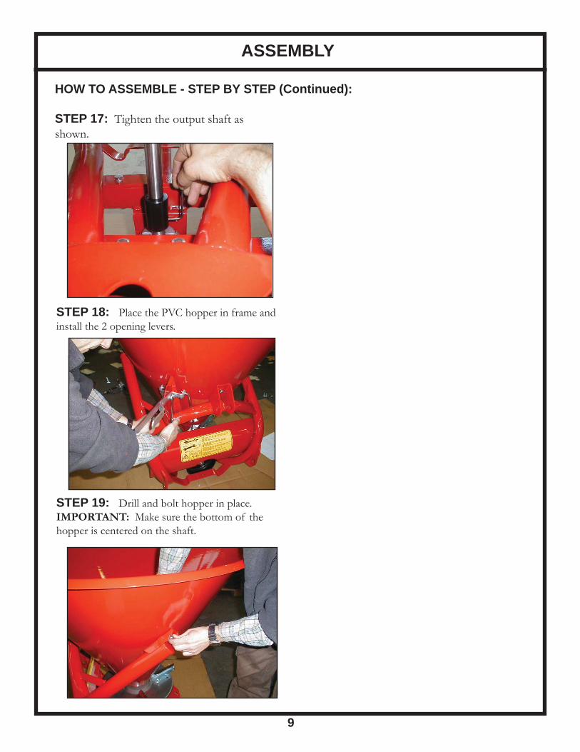
HOW TO ASSEMBLE - STEP BY STEP (Continued):
STEP 17: Tighten the output shaft as shown.
STEP 18: Place the PVC hopper in frame and install the 2 opening levers.
STEP 19: Drill and bolt hopper in place. IMPORTANT: Make sure the bottom of the hopper is centered on the shaft.
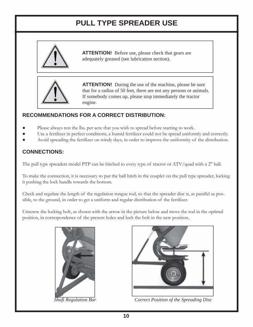
ATTENTION! During the use of the machine, please be sure that for a radius of 50 feet, there are not any persons or animals. If somebody comes up, please stop immediately the tractor engine.
ATTENTION! Before use, please check that gears are adequately greased (see lubrication section).
PULL TYPE SPREADER USE
10
RECOMMENDATIONS FOR A CORRECT DISTRIBUTION:
● Please always test the lbs. per acre that you wish to spread before starting to work.● Use a fertilizer in perfect conditions, a humid fertilizer could not be spread uniformly and correctly.● Avoid spreading the fertilizer on windy days, in order to improve the uniformity of the distribution.
CONNECTIONS:
The pull type spreaders model PTP can be hitched to every type of tractor or ATV/quad with a 2" ball.
To make the connection, it is necessary to put the ball hitch in the coupler on the pull type spreader, locking it pushing the lock handle towards the bottom.
Check and regulate the length of the regulation tongue rod, so that the spreader disc is, as parallel as pos-sible, to the ground, in order to get a uniform and regular distribution of the fertilizer.
Unscrew the locking bolt, as shown with the arrow in the picture below and move the rod in the optimal position, in correspondence of the present holes and lock the bolt in the new position..
Shaft Regulation Bar Correct Position of the Spreading Disc
ADJUSTING THE SPREAD
11
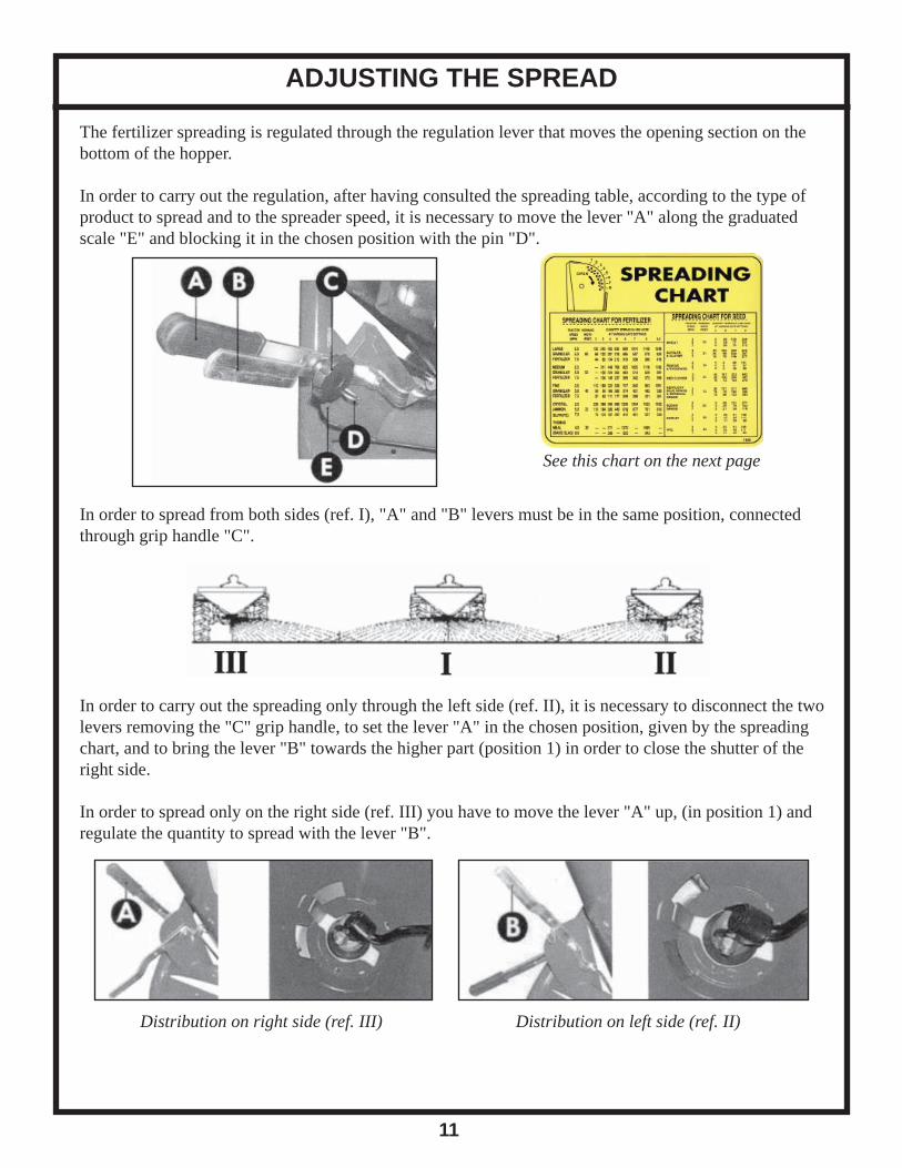
The fertilizer spreading is regulated through the regulation lever that moves the opening section on the bottom of the hopper.
In order to carry out the regulation, after having consulted the spreading table, according to the type of product to spread and to the spreader speed, it is necessary to move the lever "A" along the graduated scale "E" and blocking it in the chosen position with the pin "D".
In order to spread from both sides (ref. I), "A" and "B" levers must be in the same position, connected through grip handle "C".
In order to carry out the spreading only through the left side (ref. II), it is necessary to disconnect the two levers removing the "C" grip handle, to set the lever "A" in the chosen position, given by the spreading chart, and to bring the lever "B" towards the higher part (position 1) in order to close the shutter of the right side.
In order to spread only on the right side (ref. III) you have to move the lever "A" up, (in position 1) and regulate the quantity to spread with the lever "B".
See this chart on the next page
Distribution on right side (ref. III) Distribution on left side (ref. II)

SPREADING CHART
12

ADJUSTMENT
13
ADJUSTMENT
It is not possible to have an exact spreading chart for equipment that makes use of the centrifugal principle, as the distributed quantity depends on the speed, on the radius of distribution, on the quality and humidity of the fertilizer, and on the roughness of the land.
The fertilizer must always be stored and conserved adequately, so as to keep its physical characteristics unchanged.
HOW TO ADJUST THE SPREADER VANES
The disc vanes can be set in 4 different positions. Position #1 increases the distribution to the left. Position #4 increases the distribution to the right. For normal even spreading, use holes #2 and #3.
Spreading disc's vanes settings

FEATURES & OPTIONS
14
The spreaders are equipped with a stainless steel disc with 4 adjustable vanes in 4 diff erent positions. The vanes are bolted in place in the most used position.
The feeding of the disc is by gravity through an opening, located on the bottom of the hopper, inside of which a mix/agitator is applied, in order to prevent the fertilizer lumps formation. A sheet case is placed in front of the disc, in order to prevent the spreading in the front side of the machine.
If the material you are spreading does not fl ow evenly, a longer optional agitator is available.
If band spreading on rows is required, a one or two row band spreading attachment is available. This attachment is easy to bolt up to all models of our 3-point hitch spreaders.
Spreader Disc
Standard Agitator Lever System

LUBRICATION & SERVICE
15
Before every use and after every 8 hours of effective work, carry out the greasing of the machine.
Make sure the greasing zerks are well cleaned from mud or other residuals before using them to inject lubricating grease. Lubricate with lithium grease the points, shown in the picture.
Point to grease
REPLACEMENT OF THE SPREADER VANES
In case the spreading vanes of the disc break or get damaged, it is necessary to replace them with new ones.
Unscrew the nut and replace the damaged vane.
The fi xing items (nuts and bolts) must be of the same type as those provided from the manufacturer.
OPERATION
16
HOPPER LOAD:
It is advised not to carry out the hopper loading manually but by using suitable mechanical means.
Do not drive for very long distances with a full load and do not put full bags of the fertilizer loaded in the hopper during the transport to the fi eld or during the working, in order not to overload the capacity of the machine and to compress the fertilizer.
SPREADING OF THE FERTILIZER IN THE FIELD:
ATTENTION! - WARNING! The operator, during the period of use, maintenance, repair, transport or storing of the machine, must wear accident prevention shoes and gloves. If it is necessary, he will have, moreover, to wear headset, mask and glasses.
After having hitched the machine to the tractor and having carried out the necessary regulations, it is pos-sible to begin work.
ATTENTION! Before getting off from the ATV and before every operation of maintenance and regulation, set in action the parking brake, turn off the engine and remove the ignition key from the dashboard and wait for all moving parts to stop.
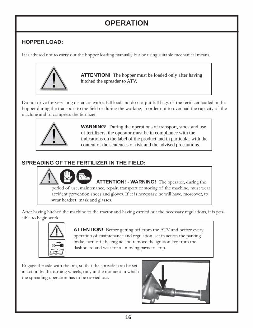
Engage the axle with the pin, so that the spreader can be setin action by the turning wheels, only in the moment in whichthe spreading operation has to be carried out.
WARNING! During the operations of transport, stock and use of fertilizers, the operator must be in compliance with the indications on the label of the product and in particular with the content of the sentences of risk and the advised precautions.
ATTENTION! The hopper must be loaded only after having hitched the spreader to ATV.

SPREADING IN FIELDS
17
Various ways exist to spread the fertilizer in the fi eld. One of the simplest methods is as follows:
1. Position the ATV/tractor at the beginning of the fi eld you intend to fertilize, to a distance (D/2) that is half of the working width that is used (point 1). 2. Drive into the fi eld distributing the fertilizer on all the perimeter. 3. Stop the tractor at one distance (D) from the point 1, equivalent to the set working width (point 2). 4. Begin the spreading proceeding in line, straight to point 3. 5. Turn the tractor and drive a D distance, equal to the working width (point 4). 6. Repeat such procedure until all the plot will be covered.

PARTS BREAKDOWN
18

PARTS BREAKDOWN
19

PARTS LIST
20
REF # QTY. PART NO. DESCRIPTION
1 4 301.012 Nut M8 UNI 5588 1 4 301.012 Nut M8 UNI 5588 (for grill) 2 3 303.007 Washer 8 x 17 UNI 6592 2 4 303.007 Washer 8 x 17 UNI 6592 (for grill) 3 7 300.030 Screw TTQST 8 x 16 UNI 5731 3 4 300.030 Screw TTQST 8 x 16 UNI 5731 (for grill) 4 1 642.001 Protective Grill CE 5 1 609.008 Hopper 180 5 1 609.038 Plastic Hopper 180 5 1 609.011 Hopper 300 5 1 609.033 Plastic Hopper 300 6 1 304.013 Rubber Ring 7 1 619.002 Lower Agitator 8 1 330.001 Entrainer 9 2 305.001 Spring Pin 8 x 40 10 4 601.001 Distributor Vane 11 3 300.023 Screw TTQST 10 x 20 UNI 5731 12 3 301.010 Nut M10 UNI 5588 16 1 300.024 Screw TE 12 x 35 UNI 5739 17 1 307.001 Split Pin 4.5 18 1 605.004 Left Shutter 19 1 605.003 Right Shutter 20 1 602.001 Right Tie Rod 21 1 602.002 Left Tie Rod 22 2 303.009 Flat Washer 10.5 x 21 UNI 6592 GR 23 1 604.002 Left Lever Short Version 71 1 604.005 Right Lever Long Version 24 1 304.008 Rubber Grip 25 1 604.001 Right Lever Short Version Bent PTP 72 1 601.006 Left Lever Long Version 26 1 302.003 Lever Lock Knob 8 x 25 27 6 301.014 Nut M10 UNI 5589 GR 30 1 610.003 Spreader Disc Without Vanes 30 1 610.013 Stainless Steel Disc Without Vanes 31 1 301.008 Self Locking Nut M12 38 4 306.002 Grease Nipple M8 44 2 305.003 Spring Pin 5 x 40 55 2 300.029 Screw TE 8 x 20 UNI 5739 56 5 301.012 Nut M8 5588 57 2 303.013 Washer 8 x 24 UNI 6593 58 1 606.009 Support Bracket 59 1 606.010 Sheet Guard 70 1 613.026 PTP Frame

PARTS LIST
21
REF # QTY. PART NO. DESCRIPTION
73 6 300.020 Screw TE 10 x 70 UNI 5737 74 8 303.015 Washer 10 x 20 UNI 6592 75 1 613.025 PTP Support Frame 76 4 325.024 Smooth Bearing w/Flange 77 2 620.079 PTP Tire 78 5 303.025 Washer 10 x 30 UNI 6593 79 10 301.013 Self Locking Nut M10 80 2 301.001 Self Locking Nut M8 81 1 620.082 PTP Right Axle 82 4 300.018 Screw TE 10 x 100 UNI 5737 83 1 322.008 Gearbox Without PTO 84 1 303.035 Washer 25 x 351.5 85 1 620.083 PTP Left Axle 86 1 302.006 Pin MM8 87 1 326.003 Key 8 x 7 x 20 88 2 305.015 Dowel M6 89 1 323.013 Output Shaft with Bushing 90 2 300.027 Screw TE 8 x 50 UNI 5737 91 1 301.006 Self Locking Nut M22 92 1 300.021 Screw TE 22 x 80 UNI 5739 93 1 613.030 Tow Tube For 1 ⅞ " Hook 94 1 613.031 Tow Tube For 2" Hook 95 2 305.008 Spring Pin R 3 96 2 633.003 PTP Pivot Dia. 22 97 1 620.080 Tow Hitch 1 ⅞ " 98 1 620.090 Tow Hitch 2" 99 1 606.061 Outer Tube Level Stop With Bushing 100 1 301.005 Tongue Nut M8 101 1 300.019 Screw TE 8 x 40 UNI 5737 102 1 606.060 Inner Tube Level Stop With Bushing 103 610.064 Stainless Steel Disc With Vanes 104 618.006 Lever Group Assembled RH & LH Short Version 104 618.013 Lever Group Assembled RH & LH Long Version 619.004 Agitator PTP Model 105 1 620.124 Shaft Support Kit 106 1 603.019 Support w/Bearing SB205-25 107 1 620.097 Bracket 108 2 300.013 Bolt 10 x 30 109 4 303.015 Washer M10 110 2 301.010 Nut M10

22
LIMITED WARRANTY
GEARMORE, INC., warrants each new Gearmore product to be free from defects in material and workmanship for a period of twelve (12) months from date of purchase to the original purchaser. This warranty shall not apply to implements or parts that have been subject to misuse, negligence, accident, or that have been altered in any way.
Our obligation shall be limited to repairing or replacement of any part, provided that such part is returned within thirty (30) days from date of failure to Gearmore through the dealer from whom the purchase was made, transportation charges prepaid.
This warranty shall not be interpreted to render us liable for injury or damages of any kind or na-ture, direct, consequential or contingent, to person or property. This warranty does not extend to loss of crops, loss because of delay in harvesting or any other expenses, for any other reasons.
Gearmore in no way warranties engines, tires, or other trade accessories, since these items are warranted separately by these respective manufacturers.
Gearmore reserves the right to make improvements in design or changes in specifi cation at any time, without incurring any obligations to owners or units previously sold.
GEARMORE, INC.13477 Benson Ave.
Chino, CA 91710Always refer to and heed machine operating warning decals on machine.
To validate the warranty on this product, please log-in to our website - www.gearmore.com. You will fi nd "warranty registration" listed at the top of our homepage.