segmented thermoelectric oxide-based module - orbit.dtu.dk · i abstract since 1990s, oxide...
TRANSCRIPT

General rights Copyright and moral rights for the publications made accessible in the public portal are retained by the authors and/or other copyright owners and it is a condition of accessing publications that users recognise and abide by the legal requirements associated with these rights.
Users may download and print one copy of any publication from the public portal for the purpose of private study or research.
You may not further distribute the material or use it for any profit-making activity or commercial gain
You may freely distribute the URL identifying the publication in the public portal If you believe that this document breaches copyright please contact us providing details, and we will remove access to the work immediately and investigate your claim.
Downloaded from orbit.dtu.dk on: Aug 26, 2019
Segmented Thermoelectric Oxide-based Module
Le, Thanh Hung
Publication date:2014
Document VersionPublisher's PDF, also known as Version of record
Link back to DTU Orbit
Citation (APA):Le, T. H. (2014). Segmented Thermoelectric Oxide-based Module. Department of Energy Conversion andStorage, Technical University of Denmark.

SEGMENTED THERMOELECTRIC OXIDE-BASED MODULE
Ph.D. Thesis
By
Lê Thanh Hùng
Principle supervisor: Prof. Nini Pryds
Co-supervisors: Dr. Ngo Van Nong
Prof. Søren Linderoth
Department of Energy Conversion and Storage
Technical University of Denmark
Roskilde, Denmark
September 2014

I
Abstract
Since 1990s, oxide thermoelectrics have been considered as promising thermoelectric (TE)
materials due to their non-toxicity, low-cost, and chemical stability at high temperatures. Studied
results show great potential for applications in thermoelectric power generator (TEG) at high
temperature and thus have drawn attentions over the years. However, oxides TEGs are still not used
broadly due to their low performance. This thesis targets the research and development of exploring
the use of these materials in high temperatures range using high conversion efficiency TEG based
modules. This study demonstrates an effective way to improve the efficiency of oxide TEG by
segmentation of oxide materials with other high-performance non-oxide materials, thereby,
extending the temperature range.
This thesis was started by developing of n-type oxide material e.g. CaMnO3 as possible
alternative n-type candidate for a more stable high temperature material. In this study, thermoelectric
properties from 300 to 1200 K of Ca0.9Y0.1Mn1-xFexO3 for 0 ≤ x ≤ 0.25 were systematically
investigated in term of Y and Fe co-doping at the Ca- and Mn-sites, respectively. It was found that
with increasing the content of Fe doping, the Seebeck coefficient of Ca0.9Y0.1Mn1-xFexO3 tended to
increase, while the tendency towards the electrical conductivity was more complicated. Thermal
conductivity of the Fe-doped samples showed a lower value than that of the non-doped sample. The
maximum dimensionless figure-of-merit, zT was found to be improved about 20% for the sample
with x = 0.05 as compared to that of the x = 0 sample at 1150 K.
High-performance segmented legs/unicouples based on oxide materials are first designed by
numerical modelling. The criteria of material selection for segmentation are based on their
“efficiency ratio” described the total conversion efficiency per the materials cost and their
compatibility factors. The numerical modeling results (chapter 3) showed that the maximum
theoretical conversion efficiency of segmented legs/unicouples could be over 10%, which is more
than twice as compared with the one comprised from non-segmented oxide elements. The calculation
also takes into account the interfacial contact resistances to evaluate the influence on the total
conversion efficiency. The obtained modeling results provide useful tools for designing future low-
cost, high-performance segmented TEGs.
A high-performance segmented oxide-based module comprising of 4-unicouples using
segmentation of the half-Heusler Ti0.3Zr0.35Hf0.35CoSb0.8Sn0.2 and the misfit-layered cobaltite
Ca3Co4O9+ as the p-leg and 2% Al-doped ZnO as the n-leg was successfully fabricated and
characterized. The results (presented in Chapter 5) show that at a temperature difference of 700 K,
the maximum output power density attains a value of 6.5 kW/m2, which is three times higher than
that of a non-segmented oxide module under the same condition. Initial long-term stability test of the
module at hot and cold side temperature of 1073/444 K showed a promising result, although a slight
degradation tendency could be observed after 48 hours of operating in air. Nevertheless, the total
II
conversion efficiency of this segmented module is still low less than 2%, and needs to be further
improved. A degradation mechanism was observed, which attributed to the increase in the interfacial
contact resistance between the n-type material (doped ZnO) and the metal electrode.
The next study (Chapter 6) focuses on enhancing the efficiency of a single oxide-based
segmented leg by further reducing the contact resistance and employing materials with better TE
properties, i.e. a p-type leg that consists of misfit-layered cobaltite Ca2.8Lu0.15Ag0.05Co4O9+ nano-
composite and the half-Heusler Ti0.3Zr0.35Hf0.35CoSb0.8Sn0.2 alloy. For the first time, a maximum
conversion efficiency as high as 5% at a T 756 K was measured. This high efficiency segmented
leg is also tested for over two weeks at the hot and cold side temperatures of 1153/397 K, showing
good durability as a result of stable, low electrical resistance contacts.

III
Abstract (Danish)
Siden 1990'erne, har oxid termoelektriske materialer været betragtet som lovende termoelektriske
(TE) materialer på grund af fraværet af giftige stoffer, lave omkostninger og kemisk stabilitet ved
høje temperaturer. Resultaterne viser store muligheder for anvendelser i termoelektriske generatorer
(TEG) ved høj temperatur og har derfor tiltrukket sig opmærksomhed gennem årene. Men oxid
TEG’er bruges stadig ikke bredt på grund af deres lave ydelse. Denne afhandling er fokuseret på
forskning og udvikling for at udforske brugen af disse materialer ved høje temperaturer ved hjælp af
TEG baseret moduler med høj konverteringseffektivitet. Denne undersøgelse viser en effektiv måde
at forbedre effektiviteten af oxid TEG ved segmentering af nitrogenoxid materialer med andre
højtydende ikke-oxid materialer for derved at udvide temperaturintervallet.
Denne afhandling starter med udviklingen af n-type oxid materialer fx CaMnO3 som mulig
alternativ n-type kandidat til et mere stabilt høj-temperatur materiale. I denne undersøgelse, blev
termoelektriske egenskaber fra 300 K til 1200 K af Ca0.9Y0.1Mn1-xFexO3 for 0 ≤ x ≤ 0,25
systematisk undersøgt på med henblik på Y og Fe dotering på Ca- og Mn-pladserne, henholdsvis.
Det blev konstateret, at med et stigende indhold af Fe dotering har Seebeck koefficient på
Ca0.9Y0.1Mn1-xFexO3 tendens til at stige, mens den elektriske ledningsevne var mere kompliceret.
Varmeledningsevnen af de Fe-doterede prøver viste en lavere værdi end for den ikke-doterede
prøve. Den maksimale dimensionsløse “figure of merit”, zT, konstateredes at blive forbedret
omkring 20 % i prøven med x = 0,05 i forhold til x = 0 prøven ved 1150 K.
Højtydende segmenterede ben/unicouples baseret på oxid materialer er først designet ved
numerisk modellering. Kriterierne i materialevalget er baseret på deres "effektivitets forhold" som er
den samlede konverteringseffektivitet pr. materiale omkostning, og deres kompatibilitets faktorer.
Numerisk modellerings resultater (kapitel 3), viste, at den maksimale teoretiske
konverteringseffektivitet på segmenterede ben/unicouples kunne være over 10 %, hvilket er mere end
det dobbelte af den fra ikke-segmenterede oxid elementer. Beregningen tager også hensyn til
grænseflade kontaktmodstand for at vurdere indflydelsen på den samlede konverteringseffektivitet.
De opnåede modellerings resultater giver et nyttigt værktøj til at designe fremtidens billige,
højtydende segmenteret TEGs.
Et højtydende segmenteret oxid-baseret modul bestående af 4-unicouples ved hjælp af
segmentering af halv-Heusler materialet Ti0.3Zr0.35Hf0.35CoSb0.8Sn0.2 og den utilpassede-lags koboltit
Ca3Co4O9 som p-ben og 2% Al-doteret ZnO som n-ben er blevet fremstillet og karakteriseret.
Resultaterne (præsenteret i kapitel 5) viser, at ved en temperaturforskel på 700 K opnår den en
maksimal effekttæthed på 6.5 kW/m2, hvilket er tre gange højere end for et ikke-segmenteret oxid
modul under samme betingelser. Indledende langtidsstabilitet af modulet med varm og kold side
temperaturer på henholdsvis 1073 K og 444 K, viste et lovende resultat, selv om en lille tendens til
nedbrydning kunne konstateres efter 48 timers operation i luft. Ikke desto mindre er den samlede
konverteringseffektivitet på dette segmenterede modul stadig lav, mindre end 2%, og skal forbedres
yderligere. Den observerede nedbrydnings mekanisme tilskrives stigningen i grænseflade
kontaktmodstand mellem n-type materialet og metal elektroden.

IV
Den næste undersøgelse (kapitel 6) fokuserer på at styrke effektiviteten af et enkelt oxid-baseret
segmenteret ben ved yderligere at reducere kontakt modstanden og benytte materialer med bedre TE
egenskaber, dvs p-type ben bestående af utilpassede-lags koboltit Ca2.8Lu0.15Ag0.05Co4O9 + nano-
komposit og en halv-Heusler Ti0.3Zr0.35Hf0.35CoSb0.8Sn0.2 legering. For første gang blev en maksimal
konverteringseffektivitet på ~5 % ved ∆T 756 K målt. Dette højeffektive segmenterede ben er også
testet i over to uger ved varm- og koldside temperaturer på henholdsvis 1153 K og 397 K, hvor det
udviser god holdbarhed som følge af stabile, lav-modstands elektriske kontakter.

V
Table of Contents
Abstract ................................................................................................................................................. I
Abstract (Danish) .............................................................................................................................. III
Table of Contents ................................................................................................................................ V
Acknowledgements ........................................................................................................................ VIII
List of Publications ........................................................................................................................... IX
List of Figures .................................................................................................................................... XI
List of Tables ...................................................................................................................................XIV
Chapter 1 Introduction ........................................................................................................................ 1
1.1 Thermoelectric effects .................................................................................................................. 1
1.2 Thermoelectric figure-of-merit and materials .............................................................................. 2
1.3 Thermoelectric power generation ................................................................................................. 3
1.3.1 Thermoelectric module ......................................................................................................... 3
1.3.2 High temperature oxide thermoelectric modules .................................................................. 6
1.3.3 Segmented thermoelectric modules ...................................................................................... 7
1.4 Thesis outline ............................................................................................................................... 9
Chapter 2 Experimental methods ..................................................................................................... 11
2.1 Spark Plasma Sintering .............................................................................................................. 11
2.2 Joining segmented leg ................................................................................................................ 12
2.3 Module fabrication ..................................................................................................................... 13
2.4 Characterization ......................................................................................................................... 14
2.4.1 Contact resistances .............................................................................................................. 14
2.4.2 Module power generation characteristics ............................................................................ 15
Chapter 3 Segmentation of low-cost, high efficiency oxide-based thermoelectric materials ...... 17
3.1 Introduction ................................................................................................................................ 18
VI
3.2 Calculation model ...................................................................................................................... 19
3.3. Results and discussion ............................................................................................................... 20
3.3.1 Material selection ................................................................................................................ 20
3.3.2 Efficiency of individual segmented legs ............................................................................. 24
3.3.3 Segmented unicouples ......................................................................................................... 25
3.4 Conclusions ................................................................................................................................ 27
Chapter 4 High-temperature thermoelectric properties of Ca0.9Y0.1Mn1-xFexO3 (0 ≤ x ≤ 0.25) .. 28
4.1 Introduction ................................................................................................................................ 29
4.2 Experimental .............................................................................................................................. 29
4.3 Results and discussion ................................................................................................................ 30
4.4 Conclusion .................................................................................................................................. 36
Chapter 5 Segmented thermoelectric oxide-based module ............................................................ 37
5.1 Introduction ................................................................................................................................ 38
5.2 Modeling .................................................................................................................................... 39
5.2.1 Formulation of the model .................................................................................................... 39
5.2.2 Calculation results ............................................................................................................... 40
5.3 Experimental procedures ............................................................................................................ 42
5.3.1 Thermoelectric materials ..................................................................................................... 42
5.3.2 Segmentation ....................................................................................................................... 43
5.3.3 Module fabrication .............................................................................................................. 43
5.3.4 Characterization................................................................................................................... 43
5.4 Results and discussion ................................................................................................................ 46
5.4.1 TE properties of the materials ............................................................................................. 46
5.4.2 Interfacial Contacts.............................................................................................................. 46
5.4.3 Power generation characteristics of the modules ................................................................ 47

VII
5.5 Conclusions ................................................................................................................................ 52
Chapter 6 High performance p-type segmented leg of misfit-layered cobaltite and half-Heusler
alloy ..................................................................................................................................................... 53
6.1 Introduction ................................................................................................................................ 54
6.2 Modelling ................................................................................................................................... 55
6.2.1 Calculation model................................................................................................................ 55
6.2.2 Efficiency of single materials and segmented legs.............................................................. 56
6.3 Experimental procedures ............................................................................................................ 57
6.3.1 Materials preparation and characterization ......................................................................... 57
6.3.2 Segmented legs fabrication and characterization ................................................................ 58
6.4 Results and discussion ................................................................................................................ 59
6.4.1 Electrical properties of single and segmented legs.............................................................. 59
6.4.2 Thermopower at small and large ∆T ...................................................................................... 60
6.4.3 Power generation characteristics ......................................................................................... 61
6.4.4 Long-term stability investigation ........................................................................................ 63
6.5 Conclusions ................................................................................................................................ 64
Chapter 7 Summaries and outlooks ................................................................................................. 66
References ........................................................................................................................................... 68

VIII
Acknowledgements
None of this work would have been possible without the guidance of my supervisors Dr. Ngo Van
Nong, Prof. Nini Pryds, and Prof. Søren Linderoth. I have learnt, through them, the spirit of research –
from basic lab skills and data analysis, to how to construct and write a scientific paper. My supervisors
always motivate and guide me on how to approach and obtain the best results. More importantly, they
have taught me how a scientific study should be done and how to deal with a problem, ranging from the
general to the specific. I would like to take this opportunity to express my deep thanks to them.
I would like to express my sincere thanks to people in thermoelectric groups Li Han, Tim Holtage,
NingYu Wu, Pham Hoang Ngan, Dennis Valbjørn Christensen, Ali Sarhadi, Rasmus Bjørk, Dan
Eriksen, and Kaspar Kirstein Nielsen, who have helped, supported and brought me memorable
during my Ph.D. study. I would also like thanks to Christian Bahl for helping in the translation of
the thesis abstract, Eugen Stamate and Feisal Kroushawi for their assisting in sputtering system.
Thanks to our laboratory technicians and engineers Steen Bang, Ebtisam Abdellahi, Karl Thydén,
Pernille Hedemark Nielsen, Annelise Mikkelsen, Agnes Kjøller, Henrik Paulsen, Xiufu Sun,
Carsten Gynther Sørensen, and John Johnson for the practical laboratory works and safety issues. I
would like to give special thanks to Jørgen Geyti and Søren Kock for helping in building up the
Rig-test thermoelectrics. Thanks to our secretary Anita Voss, Lene Thorsted, and Heidi Pedersen
for helping me with the administrative work.
I would also like to give many thanks to our international collaborators Jeff Snyder, Benjamin Balke,
Michitaka Ohtaki, Bo Brummerstedt Iversen, Man Hoang Viet, Dang Le Minh, and Kasper Andersen
Borup, who have helped me immensely with modeling thermoelectrics, half-Heusler materials and
Hall measurement.
I would like to express my sincere thanks to the assessment committee members Dr. Luise Theil
Kuhn, Prof. Lasse Aistrup Rosendahl, and Dr. Yaniv Gelbstein for evaluating and assessing my
thesis.
I would like to acknowledge our department, DTU Energy Conversion, for preciously supporting my
study. Thanks to the Programme Commission on Energy and Environment (EnMi) which is part of
the Danish Council for Strategic Research (Contract No. 10-093971), for financially supporting my
research work which is part of the OTE-POWER project.
I would also like to express my deep gratitude to Nong’s family for unlimitedly helping, sharing and
caring for us since we moved to Denmark.
Lastly, my deepest gratitude goes to my family, my parents, my wife and my son for their unending
support and encouragement. They are always with me – through anything and everything.
IX
List of Publications (During PhD study only)
Peer-reviewed Papers:
[1] Le Thanh Hung, Ngo Van Nong, Li Han, Dang Le Minh, Kasper A Borup, Bo B. Iversen,
Nini Pryds, Søren Linderoth, “High-temperature Thermoelectric Properties of Ca0.9Y0.1Mn1-
xFexO3 (0 ≤ x ≤ 0.25),” J. Mater. Sci. 48, 2817 (2013).
[2] Le Thanh Hung, Ngo Van Nong, Søren Linderoth, and Nini Pryds. “Segmentation of low-
cost, high efficiency oxide-based thermoelectric materials”, Phys. Status Solidi A, 1–8 (2015)
/ DOI 10.1002/pssa.201431626..
[3] Le Thanh Hung, Ngo Van Nong, G. Jeffrey Snyder, Li Han, Eugen Stamate, Man Hoang
Viet, Benjamin Balke, Søren Linderoth, and Nini Pryds, “High Performance p-type
Segmentation of Oxide and Half-Heusler Alloy”, Energy Conversion and Management, under
review, (2014).
[4] Le Thanh Hung, Ngo Van Nong, G. Jeffrey Snyder, Benjamin Balke, Li Han, Rasmus Bjørk,
Pham Hoang Ngan, Tim C. Holgate, Søren Linderoth, and Nini Pryds, “Segmented
thermoelectric oxide-based module,” Energy, under review, (2014).
[5] Li Han, Ngo Van Nong, Thanh Hung Le, Tim Holgate, Nini Pryds, Michitaka Ohtaki, and
Søren Linderoth, “The Influence of α- and γ-Al2O3 Phases on the Thermoelectric Properties
of Al-doped ZnO,” J. Alloys Compd. 555, 291 (2013).
[6] Li Han, Thanh Hung Le, Ngo Van Nong, Nini Pryds, and Søren Linderoth, “The Influence of
Spark Plasma Sintering Temperature on the Microstructure and Thermoelectric Properties of
Al,Ga Dual-Doped ZnO,” J. Electron. Mater. 42, 1573 (2013).
[7] Pham Hoang Ngan, Dennis Valbjørn Christensen, Gerald Jeffrey Snyder, Le Thanh Hung,
Søren Linderoth, Ngo Van Nong, and Nini Pryds, “Towards High Efficiency Segmented
Thermoelectric Unicouples”, physica status solidi (a) 211: 9–17 (2014).
[8] Li Han, Ngo Van Nong, Wei Zhang, Thanh Hung Le, Tim Holgate, Kazunari Tashiro,
Michitaka Ohtaki, Nini Pryds, and Søren Linderoth, “Effects of morphology on the
thermoelectric properties of Al-doped ZnO”, RSC Adv. 4, 12353 (2014).
Conference Presentations
[1] Le Thanh Hung, Li Han, Eugen Stamate, Benjamin Balke, Pham Hoang Ngan, Søren
Linderoth, Ngo Van Nong, and Nini Pryds, “Preparation and characterization of segmented
p-type Ti0.3Zr0.35Hf0.35CoSb0.8Sn0.2/Ca3Co4O9” Part of: Proceedings of the MRS 2013 Fall
Meeting, 2013, Presented at: Materials Research Society 2013 Fall, Boston (Oral).

X
[2] Le Thanh Hung, Ngo Van Nong, Pham Hoang Ngan, Li Han, Tim Holgate, Søren Linderoth,
and Nini Pryds “Fabrication and performance of high temperature segmented thermoelectric
oxide-based module” Part of: Proceedings of the 32nd International Conference on
Thermoelectrics, 2013, Presented at: 32nd International Conference on Thermoelectrics, 2013,
Kobe (Poster).
[3] Le Thanh Hung, Ngo Van Nong, Søren Linderoth, and Nini Pryds, “High-temperature
segmented thermoelectric oxide module using p-type Ca3Co4O9 and n-type
ZnAlO/CaMn0.95Nb0.05O3 legs”, Presented at: 6th International Workshop on Advanced
Materials Science and Nanotechnology, 2012, Ha Long City (Oral).
[4] Le Thanh Hung, Ngo Van Nong, Pham Hoang Ngan, Dan Eriksen, Li Han, Søren Linderoth,
and Nini Pryds, “High-temperature Oxide Thermoelectric Modules With p-type Ca3Co4O9
and n-type Al-doped ZnO Legs,” Presented at: 31st International & 10th European
Conference on Thermoelectrics, 2012, Aalborg (Oral).
[5] Le Thanh Hung, Ngo Van Nong, Li Han, Dang Le Minh, Nini Pryds, and Søren Linderoth,
“High-temperature Thermoelectric Properties of Ca0.9Y0.1Mn1-xFexO3 (0 ≤ x ≤ 0.25)” Part of:
Proceedings of the E-MRS 2012 Spring Meeting, 2012, Presented at: European Materials
Research Society 2012, Strasbourg (Poster).

XI
List of Figures
Figure 1.1 Schematic of Seebeck effect in a thermoelectric material. (a) The thermoelectric material
contains majority charge carriers of p-type or n-type. (b) A potential difference is built up when
applied a temperature gradient on the thermoelectric material. (c) The power output generates in the
completing circuit apply an external load. ............................................................................................. 1
Figure 1.2 Schematic dependence of zT, Seebeck coefficient, electrical conductivity (1/) and
thermal conductivity on the carrier concentration of a thermoelectric material [3]. ............................. 2
Figure 1.3 The material figure-of-merit, zT, of selected state-of-the-art p-type (a) and and n-type (b)
for various temperature range. ............................................................................................................... 3
Figure 1.4 Schematic thermoelectric module consists of 27 couples of p-type and n-type with the
direction of heat and charge flows. The figure is taken from Ref. [3]. .................................................. 4
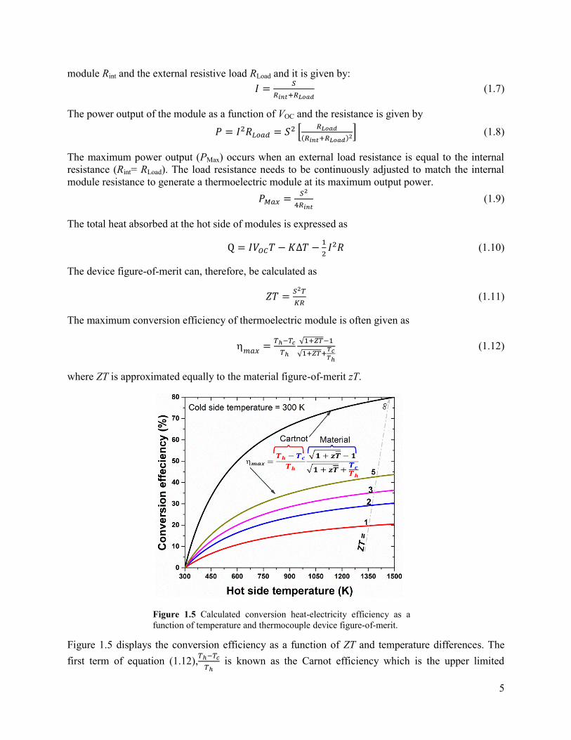
Figure 1.5 Calculated conversion heat-electricity efficiency as a function of temperature and
thermocouple device figure-of-merit. .................................................................................................... 5
Figure 1.6 Schematic drawing of one-stage of (a) single material, (b) segmented two-material and (c)
two-stage of cascaded thermoelectric generators. A, C and D are materials with high electrical and
thermal conductivity. B is a material with high thermal conductivity and electrically insulating, in
order to expect that there is no temperature gradient between A and C [6]........................................... 7
Figure 2.1 Schematic representation of the park plasma sintering (SPS) process [135]. ................... 11
Figure 2.2 Schematic configuration of the brazing joining oxide-metallic alloys used spark plasma
sintering as hot press without current passing through the sample. ..................................................... 12
Figure 2.3 A proven picture of segmented half-Heusler/oxide legs were successfully joined by silver
brazing method. .................................................................................................................................... 13
Figure 2.4 Schematic of the whole thermoelectric module construction process from sintering and
characterized materials to modelling, built up and test modules. ........................................................ 14
Figure 2.5 Schematic of the fixture used to measure the electrical contact resistances. (a) The darker
shaded material is the Ca3Co4O9 or 2% Al doped ZnO and the sign convention of the current is for
forward current mode. (b) A real picture of a fixture used to measure ASR. (c) Schematic
configuration of the voltage probes along the segmented leg. ............................................................. 15
Figure 2.6 (a) Schematic illustration of module tester. (b) The complete view of the Rig-test used to
measure the power generation characteristics of legs and modules in this thesis. ............................... 16
Figure 3.1 The material figure-of-merit zT and their compatibility factor s of selected state-of-the-art
p-type (a and b) and n-type (c and d) for various temperature range. .................................................. 21
Figure 3.2 A plot of price in dollars per mole (a) and (b) efficiency ratio for various high-
temperature TE materials. .................................................................................................................... 22
Figure 3.3 (a) Temperature dependence of the s and the u. (b) local and reduced efficiencies using
value of u for highest efficiency compared to the maximum reduced efficiency for n-type segmented

XII
CoSb/ZnO and HH/ZnO legs. (c) Total efficiency of single components, incompatible segmented leg
CoSb/ZnO and compatible segmented HH/ZnO. ................................................................................ 23
Figure 3.4 The diagram of the maximum total efficiencies of the state-of-the-art oxide-based
segmented legs (solid column), and their device ZTs (pattern column). ............................................. 24
Figure 3.5 The influence of contact resistance on the total efficiency of unicouple comprised from p-
BiTe/HH/Ca3Co4O9 and n-BiTe/HH/ZnO. .......................................................................................... 26
Figure 4.1 X-ray diffraction patterns of CaMnO3 and Ca0.9Y0.1Mn1-xFexO3 with x = 0, 0.05, 0.1, 0.15,
0.2, 0.25 samples after calcining at 1273 K for 24 h in air. ................................................................. 30
Figure 4.2 X-ray diffraction patterns of a typical sample Ca0.9Y0.1Mn0.95Fe0.05O3: (a) Rietveld
refinement profile of the calcined powder, (b) pellet sample sintered by SPS at 1173 K under
pressure 50 MPa for 8 minutes under Ar atmosphere, (c) SPS sample after annealing at 1523 K in air
for 24 h. ................................................................................................................................................ 31
Figure 4.3 Lattice parameters and cell volume of Ca0.9Y0.1Mn1-xFexO3 as function of Fe content (x). ...... 32
Figure 4.4 Temperature dependence of the electrical conductivity for Ca0.9Y0.1Mn1-xFexO3 with x = 0,
0.05, 0.1, 0.15, 0.2, 0.25 SPS sintered samples; Inset, the activation energies were fitted from
experimental data. ................................................................................................................................ 33
Figure 4.5 Temperature dependence of the Seebeck coefficient for Ca0.9Y0.1Mn1-xFexO3 with x = 0,
0.05, 0.1, 0.15, 0.2, and 0.25 SPS sintered samples. ............................................................................ 33
Figure 4.6 Temperature dependence of (a) the Seebeck coefficient (solid symbols) and the electrical
conductivity (open symbols), and (b) the power factors for all the SPS sintered samples Ca0.9Y0.1Mn1-
xFexO3 with x = 0, 0.05, 0.1, 0.15, 0.2, 0.25 and selective samples with x = 0, 0.05, 0.1, 0.15 after
annealing annealed at 1523 K for 24 h in air. ...................................................................................... 34
Figure 4.7 SEM images from fractured surfaces of a typical Ca0.9Y0.1Mn1-xFexO3 with x = 0.05
sample: a) sample was sintered by SPS, b) sample was annealed at 1523 K for 24 h in air flow. ...... 35
Figure 4.8 The total thermal conductivity (total), the electronic and phonon components (e and ph)
of Ca0.9Y0.1Mn1-xFexO3 samples with x = 0, 0.05, 0.1, 0.15 as a function of temperature. .................. 35
Figure 4.9 The dimensionless figure-of-merit (zT) as a function of temperature for Ca0.9Y0.1Mn1-xFexO3
with x = 0, 0.05, 0.1, 0.15 selective SPS samples after heated treatment at 1523 K for 24 h in air. ............ 36
Figure 5.1 (a)Temperature dependences of zT and s of p-type Ca349 and HH alloys. (b) Absolute
efficiencies of p-type Ca349, HH and segmented HH/Ca349. ............................................................ 41
Figure 5.2 1D and 3D calculated efficiency as a function of the cross-sectional area ratio Ap/An at
Th/Tc = 1173/300 K for 4 couples of NTEG and STEG with Zn0.98Al0.02O as n-legs. ......................... 42
Figure 5.3 Configurations of the electrical contact resistance measurement for the non-segmented leg
(a) and the segmented leg (b). .............................................................................................................. 44
Figure 5.4 Temperature dependence of the Seebeck coefficient and power factor of (a) p-type Ca349
and Ti0.3Zr0.35Hf0.35CoSb0.8Sn0.2 and (b) n-type 2% Al-doped ZnO. .................................................... 46

XIII
Figure 5.5 (a) Contact resistance of, Ag electrode with Ca349, (b) Ag electrode with 2% Al doped
ZnO, (c) the contact resistance of HH/Ag/Ca349 was extracted from sandwich structure and single
component Ca349 and HH. .................................................................................................................. 47
Figure 5.6 Voltages and output power for the 4 p-n couples NTEG (a) and STEG (b) as a function of
current under different temperature gradient. ...................................................................................... 48
Figure 5.7 The open voltage and maximum output power of NTEG and STEG as a function of
temperature differences, T. Inserted photos showing the actual segmented and non-segmented modules.
(b) 3D modeling results used experimental measurement data of STEG with and without heat losses
(Qloss) and total contact resistances (Rc) at hot and cold side temperatures of 1173/473 K. ......................... 51
Figure 5.8 The long term stability test of STEG in air at hot and cold sides of 1073/444 K. ............. 51
Figure 6.1 Selected dimensionless figure-of-merit zT of state of the art p-type TE materials, (b)
temperature dependence of compatibility factors of MnSi, HH and CCO. (c) Calculated efficiency of
single CCO, HH and segmented HH/CCO. ......................................................................................... 56
Figure 6.2 (a) Schematic configuration of the voltage probes along the segmented leg. (b) Images of
the fabricated segmented HH/CCO legs. (c) Schematic of the long-term stability measurement
configuration using test Rig system. .................................................................................................... 58
Figure 6.3 (a) Temperature dependence of the electrical resistivity of CCO, HH, and segmented
HH/CCO. Star symbol curve denotes the calculated electrical resistivity. (b) The electrical contact
resistance of joint interface HH/Ag/CCO as a function of temperature, inset SEM picture of
HH/Ag/CCO. ....................................................................................................................................... 59
Figure 6.4 (a) Temperature dependence of Seebeck coefficient of CCO, HH, segmented HH/CCO
legs at small temperature gradient. (b) The calculated and experimental total Seebeck coefficient of
the segmented leg HH/CCO under large temperature gradient. .......................................................... 60
Figure 6.5 (a) Voltages and output power for the segmented HH/CCO legs as a function of current
density under different temperature gradient. (b) The experiment and calculation of V(J) and the
efficiency of the segmented legs with and without the electrical contact resistances at highest
temperature difference. ........................................................................................................................ 62
Figure 6.6 The long term stability test of the HH/Ag/CCO leg in air under hot and cold side
temperatures of 1153/397 K. ................................................................................................................ 63
Figure 6.7 SEM joint interface of CCO/Ag and HH/Ag after joining 0 Hrs and after test 336 Hrs in
air with hot and cold side temperatures of 1153/397 K. ...................................................................... 64

XIV
List of Tables
Table 1.1 Research progress on the power generation characteristics of oxide thermoelectric modules. ....... 6
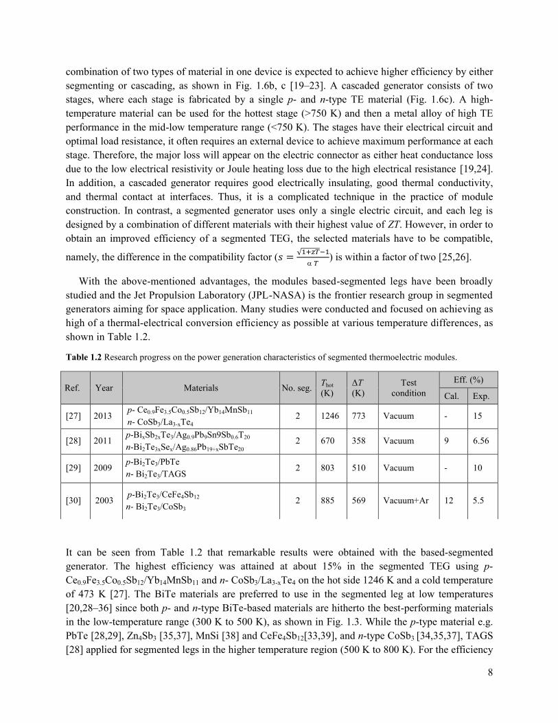
Table 1.2 Research progress on the power generation characteristics of segmented thermoelectric
modules.......................................................................................................................................8
Table 3.1 The possible materials for segmenting legs of p-Ca3Co4O9 and n-ZnO ............................. 24
Table 3.2 Maximum efficiency of unicouples with various combination of p-n leg. ......................... 25
Table 4.1 Structural refinement factors, lattice parameters and cell volumes of Ca0.9Y0.1Mn1-xFexO3. ...... 32
Table 4.2 Relative densities and electrical characteristics of Ca0.9Y0.1Mn1-xFexO3. ............................ 34
Table 5.1 The experimental measurement conditions and uncertainty. .............................................. 45
Table 5.2 The power generation characteristics of oxide-based thermoelectric modules reported in
literatures. ............................................................................................................................................. 50
1
Chapter 1 Introduction
In this chapter, the basic principles of thermoelectric effects, materials, and modules are
introduced. It also contains an overview of current high-temperature non-segmented and segmented
thermoelectric modules, and their typical applications and developing progress. An outline of the
thesis is presented at the end of this chapter.
1.1 Thermoelectric effects
The thermoelectric effect is the direct conversion of a temperature gradient to electricity
(Seebeck effect) and vice versa (Petier effect). Since this study mainly focuses on power generation,
the Seebeck effect will be described in more detail.
The Seebeck effect was discovered in 1821 by the physicist and chemist Dr. Med. Thomas
Johann Seebeck (1770–1831) [1,2]. In general, the Seebeck effect can be described as shown in
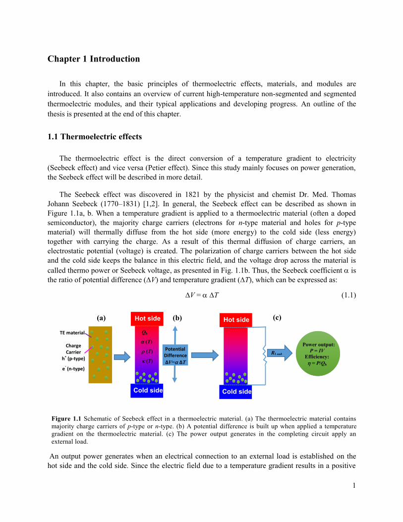
Figure 1.1a, b. When a temperature gradient is applied to a thermoelectric material (often a doped
semiconductor), the majority charge carriers (electrons for n-type material and holes for p-type
material) will thermally diffuse from the hot side (more energy) to the cold side (less energy)
together with carrying the charge. As a result of this thermal diffusion of charge carriers, an
electrostatic potential (voltage) is created. The polarization of charge carriers between the hot side
and the cold side keeps the balance in this electric field, and the voltage drop across the material is
called thermo power or Seebeck voltage, as presented in Fig. 1.1b. Thus, the Seebeck coefficient is
the ratio of potential difference (∆V) and temperature gradient (∆T), which can be expressed as:
∆V = ∆T (1.1)
An output power generates when an electrical connection to an external load is established on the
hot side and the cold side. Since the electric field due to a temperature gradient results in a positive
Figure 1.1 Schematic of Seebeck effect in a thermoelectric material. (a) The thermoelectric material contains
majority charge carriers of p-type or n-type. (b) A potential difference is built up when applied a temperature
gradient on the thermoelectric material. (c) The power output generates in the completing circuit apply an
external load.
Hot side
Cold side
Hot side
Cold side
Power output:
P = IV
Efficiency:
= P/Qh
Qh
(T)
(T)
(T)
Potential Difference
∆V= ∆T
RLoad
TE material
Charge Carrier
h+ (p-type)
e- (n-type)
(a) (b) (c)

2
voltage for a p-type material and a negative voltage for an n-type material, p- and n-type materials
are usually connected to form a thermocouple. The heat to electricity conversion efficiency is then
defined as the total electric power output, P, divided by the total heat input on the hot side, Qh, which
can be written as:
=𝑃
𝑄ℎ (1.2)
1.2 Thermoelectric figure-of-merit and materials
The efficiency of material is evaluated by the figure-of-merit z or the dimensionless figure-of-
merit zT, which can be expressed as
z𝑇 =2
𝑇 (1.3)
where , , , and T are the Seebeck coefficient, electrical resistivity, thermal conductivity, and
absolute temperature, respectively. The concept of figure-of-merit was first proposed by a Russian
physicist, Abram Fedorovich Ioffe, in 1949.
It can be seen from equation (1.3) that high zT requires a high value of Seebeck and a low value of
electrical resistivity and thermal conductivity in a material, as presented in Figure 1.2. The good
thermoelectric materials are of carrier concentrations of 1019 and 1021 carriers/cm3 [3]. The
optimization of the thermal conductivity is complicated by the heat transport including lattice and
electronic thermal conductivity.
Figure 1.2 Schematic dependence of zT, Seebeck coefficient, electrical conductivity (1/)
and thermal conductivity on the carrier concentration of a thermoelectric material [3].

3
Figure 1.3 shows the dimensionless figure-of-merit, zT, as a function of temperature for state-of-the-
art TE materials. The new approach of nanostructured thermoelectric material has recently been used
in reducing the lattice thermal conductivity. The results show very promising values with the peak zT
reached at about 2.2 at 915 K [4] for polycrystalline PbTe compounds or zT = 2.6 at 923 K for SnSe
single crystals [5].
1.3 Thermoelectric power generation
1.3.1 Thermoelectric module
The thermoelectric modules usually consist of several to hundreds thermoelectric couples of p-
type and n-type materials, which are connected electrically in series and thermally in parallel, as
shown in Figure 1.4. The top and bottom sides of the module are often covered by substrates that
made by material with good thermal conductance and electrical insulation such as aluminum oxide
(Al2O3) or aluminum nitride (AlN).
A thermoelectric generator uses heat flow across: heat absorbed and rejected at the hot side and the
cold side of the module, respectively, to power output through an external circuit. The voltage output
of the module is generated from the Seebeck effect. In case of the open-circuit, the output voltage
(VOC) can be expressed as [6,7]:
𝑉OC = 𝑆 = 𝑛 ∫ 𝑝(𝑇) − 𝑛(𝑇)𝑑𝑇𝑇ℎ
𝑇𝑐 (1.4)
where Th and Tc are the hot and cold side temperatures, n is the number of p-n couples, p and n are
the Seebeck coefficients of p- and n-type legs, respectively.
The thermoelectric elements are connected electrically in series. Thus, the total resistance of the
Figure 1.3 The material figure-of-merit, zT, of selected state-of-the-art p-type (a) and and n-type (b) for
various temperature range.

4
module, Rint, can be approximately defined by
𝑅𝑖𝑛𝑡 = 𝑛 (𝑛𝑙
𝐴𝑛+
𝑝𝑙
𝐴𝑝) + 𝑅𝑐 (1.5)
here, l is the length of the legs, An and Ap are the cross-sectional area of p- and n-type legs,
respectively, and Rc is the total contact resistance, which includes the electrical contact resistances at
the joined part of the leg i.e. the hot and cold side junctions.
Similarly, the total thermal conductance of the module, K, can be determined by
𝐾 = 𝑛 (𝑛𝐴𝑛
𝑙+
𝑝𝐴𝑝
𝑙) + 𝐾𝑐 (1.6)
Kc is the total thermal losses including thermal contact, heat conductance and heat radiation losses.
The magnitude of the output current, I, is proportional to the sum of the internal resistance of the
Figure 1.4 Schematic thermoelectric module consists of 27 couples of p-type and n-type
with the direction of heat and charge flows. The figure is taken from Ref. [3].
5
module Rint and the external resistive load RLoad and it is given by:
𝐼 =𝑆
𝑅𝑖𝑛𝑡+𝑅𝐿𝑜𝑎𝑑 (1.7)
The power output of the module as a function of VOC and the resistance is given by
𝑃 = 𝐼2𝑅𝐿𝑜𝑎𝑑 = 𝑆2 [𝑅𝐿𝑜𝑎𝑑
(𝑅𝑖𝑛𝑡+𝑅𝐿𝑜𝑎𝑑)2] (1.8)
The maximum power output (PMax) occurs when an external load resistance is equal to the internal
resistance (Rint= RLoad). The load resistance needs to be continuously adjusted to match the internal
module resistance to generate a thermoelectric module at its maximum output power.
𝑃𝑀𝑎𝑥 =𝑆2
4𝑅𝑖𝑛𝑡 (1.9)
The total heat absorbed at the hot side of modules is expressed as
Q = 𝐼𝑉𝑂𝐶𝑇 − 𝐾∆𝑇 −1
2𝐼2𝑅 (1.10)
The device figure-of-merit can, therefore, be calculated as
𝑍𝑇 =𝑆2𝑇
𝐾𝑅 (1.11)
The maximum conversion efficiency of thermoelectric module is often given as
𝑚𝑎𝑥
=𝑇ℎ−𝑇𝑐
𝑇ℎ
√1+𝑍𝑇−1
√1+𝑍𝑇+𝑇𝑐𝑇ℎ
(1.12)
where ZT is approximated equally to the material figure-of-merit zT.
Figure 1.5 displays the conversion efficiency as a function of ZT and temperature differences. The
first term of equation (1.12),𝑇ℎ−𝑇𝑐
𝑇ℎ is known as the Carnot efficiency which is the upper limited
Figure 1.5 Calculated conversion heat-electricity efficiency as a
function of temperature and thermocouple device figure-of-merit.

6
conversion efficiency at infinity ZT. The maximum conversion efficiency of module increased with
increasing the hot side temperature as a result of high Carnot efficiency contribution. Therefore, high
temperature thermoelectric module is of great interest in high temperature heat-electricity conversion
e.g. waste heat recovery from steel industrial and transportation sectors.
1.3.2 High temperature oxide thermoelectric modules
Oxide thermoelectric materials, consisting of abundant elements, have low-cost and
environmentally-friendly processing, and hence, have attracted great interest in the area of advanced
renewable energy. Many modules have been fabricated and characterized using a different
combination of p and n-type of TE oxide materials such as p-type Ca3Co4O9 and n-type CaMnO3 or
ZnO [8–11] or p-type NaCo2O4 and n-type ZnO [5, 7], etc. The power generation characteristics of
different oxide modules are summarized in Table 1.1.
Table 1.1 Research progress on the power generation characteristics of oxide thermoelectric modules.
* Only the modules with the number of p-n couples from 4 or higher are selected.
As seen in Table 1.1, although many combinations of p-n couples have been employed in the
oxide modules, its performance i.e. voltage, and current output are still relative low compared with
modules constructed from metallic alloys; even the experimental value of the conversion efficiency
Ref. Year Materials No. p-n
couples
Jointing
technique
Thot
(K)
ΔT
(K)
V0
(V)
Pmax
(mW)
Legs-size
(mm)
Power
Density
(mW/cm2)
[13] 2001 p-Ca2.7Bi0.3Co4O9
n-Ca0.92La0.08MnO3 8 Pt paste 773 390 0.9 63.5 33 44.1
[14] 2006 p-Ca2.7Bi0.3Co4O9
n-La0.9Bi0.1NiO3 140 Ag paste 1072 551 4.5 150 1.31.35 31.7
[5] 2006 p-NaCo2O4
n-Zn0.98Al0.02O 12
Diffusion
welding 839 462 0.8 58 3410 20.1
[16] 2006 p-Ca2.7Bi0.3Co4O9
n-CaMn0.98Mo0.02O3 8 Ag paste 897 565 1 170 554.5 42.5
[7] 2007 p-NaCo2O4
n-Zn0.98Al0.02O 12
Diffusion
welding 934 455 0.8 52.5 3410 18.2
[17] 2007 p-Ca2.7Bi0.3Co4O9
n-CaMn0.98Mo0.02O3 8 Ag 1273 975 0.7 340 554.5 85
[18] 2011 p-Ca3Co4O9
n-(ZnO)7In2O3 44 Ag paste 1100 673 1.8 423
p:1515 27
n:151518 2.1
[9] 2014 p-Ca3Co4O9
n-Zn0.98Al0.02O 6 Ag 773 248 0.12 2.26 4410 1.2

7
has not been reported yet on those oxide modules. The highest estimated number is still lower than
2%. One of the main reasons for this low result is the low performance of oxide materials in the low-
temperature range (< 750 K). To overcome the limitation mentioned above, new strategies on
improved material of zT and a new concept in module design and fabrication are needed.
1.3.3 Segmented thermoelectric modules
From equation (1.12) and Fig. 1.5, one can see that in order to achieve high conversion efficiency
of a thermoelectric power generator (TEG), both high figure-of-merit and large temperature
differences are desired. The material zT is computed from (T), (T), and (T) using Eq. (1.3)
strongly depend on temperature. The large temperatures that drop along the leg are dominated by
large change in the zT curve. In general, each material exhibits a peak zT value, which is defined as
their optimum working temperature interval. It means that for a given temperature interval, one
material may have its highest ZT while in another temperature interval, a second material will have a
higher ZT. Therefore, a TEG constructed from one material is limited to a particular operation
temperature range which is determined by the type of materials used. To overcome the limitation of
generator built-up from one material, TEGs based of two or more materials can solve this problem by
either cascaded or segmented generators as schematically showed in Figure 1.6 [6].
Fig. 1.6a presents a typical p-n unicouple made of a single material, for example, a low-
temperature BiTe, a high-temperature oxide or SiGe. In BiTe-based module, the maximum highest
temperature at the hot side is 450 K and 300 K at the cold side. When the temperature at the hot side
is higher than 450 K, the material based on BiTe cannot be sustained because of oxidation,
decomposition or volatility of the p and/or n legs. For modules made of oxide or SiGe-based
materials, their peaks zT values are obtained at 1000 K as presented in Fig. 1.2 so that the highest
device performance can only be reached at temperatures between 750 and 1200 K. Ideally, a
Figure 1.6 Schematic drawing of one-stage of (a) single material, (b) segmented two-material and (c) two-stage of
cascaded thermoelectric generators. A, C and D are materials with high electrical and thermal conductivity. B is a
material with high thermal conductivity and electrically insulating, in order to expect that there is no temperature
gradient between A and C [6].
8
combination of two types of material in one device is expected to achieve higher efficiency by either
segmenting or cascading, as shown in Fig. 1.6b, c [19–23]. A cascaded generator consists of two
stages, where each stage is fabricated by a single p- and n-type TE material (Fig. 1.6c). A high-
temperature material can be used for the hottest stage (>750 K) and then a metal alloy of high TE
performance in the mid-low temperature range (<750 K). The stages have their electrical circuit and
optimal load resistance, it often requires an external device to achieve maximum performance at each
stage. Therefore, the major loss will appear on the electric connector as either heat conductance loss
due to the low electrical resistivity or Joule heating loss due to the high electrical resistance [19,24].
In addition, a cascaded generator requires good electrically insulating, good thermal conductivity,
and thermal contact at interfaces. Thus, it is a complicated technique in the practice of module
construction. In contrast, a segmented generator uses only a single electric circuit, and each leg is
designed by a combination of different materials with their highest value of ZT. However, in order to
obtain an improved efficiency of a segmented TEG, the selected materials have to be compatible,
namely, the difference in the compatibility factor (𝑠 =√1+𝑧𝑇−1
𝑇) is within a factor of two [25,26].
With the above-mentioned advantages, the modules based-segmented legs have been broadly
studied and the Jet Propulsion Laboratory (JPL-NASA) is the frontier research group in segmented
generators aiming for space application. Many studies were conducted and focused on achieving as
high of a thermal-electrical conversion efficiency as possible at various temperature differences, as
shown in Table 1.2.
Table 1.2 Research progress on the power generation characteristics of segmented thermoelectric modules.
It can be seen from Table 1.2 that remarkable results were obtained with the based-segmented
generator. The highest efficiency was attained at about 15% in the segmented TEG using p-
Ce0.9Fe3.5Co0.5Sb12/Yb14MnSb11 and n- CoSb3/La3-xTe4 on the hot side 1246 K and a cold temperature
of 473 K [27]. The BiTe materials are preferred to use in the segmented leg at low temperatures
[20,28–36] since both p- and n-type BiTe-based materials are hitherto the best-performing materials
in the low-temperature range (300 K to 500 K), as shown in Fig. 1.3. While the p-type material e.g.
PbTe [28,29], Zn4Sb3 [35,37], MnSi [38] and CeFe4Sb12[33,39], and n-type CoSb3 [34,35,37], TAGS
[28] applied for segmented legs in the higher temperature region (500 K to 800 K). For the efficiency
Ref. Year Materials No. seg. Thot
(K)
ΔT
(K)
Test
condition
Eff. (%)
Cal. Exp.
[27] 2013 p- Ce0.9Fe3.5Co0.5Sb12/Yb14MnSb11
n- CoSb3/La3-xTe4 2 1246 773 Vacuum - 15
[28] 2011 p-BixSb2xTe3/Ag0.9Pb9Sn9Sb0.6T20
n-Bi2Te3xSex/Ag0.86Pb19+xSbTe20 2 670 358 Vacuum 9 6.56
[29] 2009 p-Bi2Te3/PbTe
n- Bi2Te3/TAGS 2 803 510 Vacuum - 10
[30] 2003 p-Bi2Te3/CeFe4Sb12
n- Bi2Te3/CoSb3 2 885 569 Vacuum+Ar 12 5.5
9
of the segmented generator, the experimental results are always smaller than the calculated one due
to a large contribution of thermal and electrical losses. The main factors that affected the conversion
efficiency are summarized by the following [20]:
The material figure-of-merit of segments is determined by a small temperature gradient, ∆T,
less than 10 K, while the devices work under large temperature differences (200 to 700 K).
The compatibility factor, s.
Interfacial contact (electrical and thermal) resistance.
Heat losses on the side of the leg.
According to results reported in Refs. [20,28,32,36,40], the functionally graded materials have been
suggested as a good solution to reduce contact resistance. In this way, the material zT could be
optimized by tuning the carrier concentration layer by layer in the TE leg; the contact resistance
between layers can be therefore negligible. However, the grade materials required similar sintering
conditions i.e. temperature, pressure and environment, which lead to limits in materials selection.
Generally, the previously-studied materials were only based on metallic compounds and the
segmented TEG measurements conducted in high vacuum or inner gas in order to protect the legs
against oxidation or sublimation. In some cases the leg is coated by protected layers [33]. Therefore,
application of these generators often requires an encapsulation process, which increases the capital
cost of modules. For high temperatures > 1000 K, the segmented materials used in Ref. [27,35]
contained large quantity ratios of rare earth elements, e.g., La, Yb, and Ce, which are very expensive
and might only be used for space application. Other inexpensive materials such as high-temperature
oxide and mid-temperature half-Heusler alloy, have not been investigated yet. Thus, a study of
segmentation based on cheap, stable, scalable materials is necessary to bring up low-cost and high
efficiency TEG for high temperatures in waste heat recovery.
1.4 Thesis outline
The thesis consists of seven chapters which cover the content of modeling segmented
thermoelectrics, development of oxide materials, the joining between oxides and metal, oxides and
alloys, and the construction of segmented thermoelectric oxide-based legs/modules. The main
scientific results and findings are presented in Chapter 3 to Chapter 6.
Chapter 1 presents the basic principles of thermoelectric effects, materials and modules. An
overview of the current study on high-temperature thermoelectric modules was also given.
In Chapter 2, all the typical experimental methods and characterization techniques used in the
thesis will be presented. They include: spark plasma sintering, joining legs, and module fabrication,
as well as contact resistance and module measurements. Other experiments for particular works will
be described in detail in each sub-chapter.
Chapter 3 will describe the modeling on segmented thermoelectrics used to predict the
performance of non-segmented and segmented leg/unicouples. Based on the study on the efficiency
ratio i.e. the conversion efficiency vs. materials cost, it shows that some oxides such as layered-
cobaltite Ca3Co4O9 and doped ZnO are good candidates for hot side materials for segmentation.
Various state-of-the-art metallic materials are selected based on the calculation results of the

10
compatibility factor and the maximum total conversion efficiency of the segmented legs. The
evaluation was carried out using a one-dimensional (1D) numerical modeling. The influence of the
interfacial contact resistance on the performance of the segmented legs/unicouples is also considered
and discussed in this chapter.
Chapter 4 presents the study on n-type oxide materials of CaMnO3. For the investigation of
CaMnO3, the Ca0.9Y0.1Mn1-xFexO3 system with 0 ≤ x ≤ 0.25 was prepared, in which Ca-site was
substituted with Y at a fixed concentration and Mn-site was partly replaced by Fe. The structural and
the thermoelectric properties of these materials are investigated in detail. The influence of Y and Fe
doping at Ca- and Mn-sites, respectively, on the crystal structure, is carefully studied by the Rietveld
refinement analysis. The correlation between the crystal structures and the thermoelectric properties
is discussed.
In Chapter 5, segmentation of the half-Heusler Ti0.3Zr0.35Hf0.35CoSb0.8Sn0.2 (HH) and the non-doped
layered-cobaltite Ca3Co4O9 is investigated both by modeling and experiments. A 4 p-n couples
segmented thermoelectric generator comprised of the segmented HH/Ca3Co4O9 as p-legs and n-legs
2% Al-doped ZnO was fabricated and characterized at various hot side temperatures up to 1173 K.
The power generation characteristics obtained experimentally for the correlation with theoretical
calculations are compared with a non-segmented oxide module built up from p-leg Ca3Co4O9 and n-
leg 2% Al-doped ZnO.
Chapter 6 focusses on the fabrication and characterization of a high efficiency segmented p-leg
building up from half-Heusler Ti0.3Zr0.35Hf0.35CoSb0.8Sn0.2 (HH) and doped Ca2.8Lu0.15Ag0.05Co4O9+.
It is found that a maximum efficiency of 5% is attained at a temperature gradient of about 756 K. In
this chapter, the influence of the contact resistance on the total conversion efficiency was also
evaluated by modeling, and correlated with the experimental results.
Finally, Chapter 7 is summary of the main findings and results of the thesis. Some future works and
outlooks are also mentioned at the end of this chapter.

11
Figure 2.1 Schematic representation of the park
plasma sintering (SPS) process [135].
Chapter 2 Experimental methods
The experimental methods used in the thesis include powder synthesis, bulk material sintering,
joining two dissimilar materials, module construction process, and characterization of materials,
single legs, segmented legs, contact resistance and device performance. In this chapter, only the
typical methods are focused on and described in detail. Other common experiments will be
mentioned in each sub-chapter.
2.1 Spark Plasma Sintering
In the fabrication of thermoelectric materials, the most-effective method used to enhance
thermoelectric performance is to make bulk nanostructured materials (pellet) consisting of separate
nanoparticles connected through “particle’s neglect” and its grain size is retention. In those materials
with nanostructures, their thermal conductivity could be reduced as a result of the increase in phonon
scattering. Therefore, retention of nano-size particles in bulk form during the sintering process is of
prime importance. In the sintering technique, spark plasma sintering (SPS) is known as a powerful
tool that can not only be used for consolidation/synthesis [41], but can also be used for
coating/joining materials [42,43]. The SPS’s principle is based on an electric current assisted
sintering technique, which simultaneously applies an electric current and mechanical pressure, as
schematically shown in Figure 2.1. With this technique, the sintered powders are consolidated and
simultaneously densified with desired shape and density [41]. It can be seen from Fig. 2.1 that the
pulse electric current can pass through both of the die and the sintered powder. The SPS processes
can be used in efficient heat input, particularly when electrical-insulating die is used the electric
current is applied to the electrical conductance punch and powder for an extremely short duration (a

12
few microseconds). The heat, therefore, will be concentrated on the sintered elements which avoid a
large quantity of heat loss to the surrounding environments. In another way, the SPS can be used as a
fast hot pressing technique without the current going through samples. In this thesis, the SPS will be
used for sintering oxide materials and semimetal half-Heusler materials as well as the joining of
metallic alloy, oxide compounds, and module fabrication.
For the sintering materials process, after calcination, milling, sieving, and checking the phase of
samples, the obtained powders were covered with graphite paper and put into graphite die. The
densified processing was carried out using a spark plasma sintering system (SPS). The SPS unit of
Dr. Sinter 515S (Syntex Inc., Japan) was used, with a pulsed direct current regulated by the on/off
settings, with each pulse lasting 3.3 ms and having a 12:2 on/off ratio. For the sintering parameters, a
constant uniaxial pressure of 50 MPa, was used. The samples were heated to setting temperature e.g.
1123 K for p-type oxide Ca3Co4O9 and Ca2.8Lu1.5Ag0.05Co4O9+δ while a uniaxial pressure of 50 MPa
was applied for holding 5 min. During the experiment, the temperature, applied pressure, and
displacement or shrinkage of the sample were recorded. The as-prepared samples were then polished
to remove the graphite foil. The details of these works can be seen elsewhere [8,44–46].
2.2 Joining segmented leg
Metal-ceramic joining has a long history.
Egyptians first used it to cover their enamels
several centuries B.C [47]. In general, joining
provides a new structured ceramics in a way that
manufacturing components cannot be made in
one piece. This method is cheaper than others
[47,48]. There are several joining techniques
which can be roughly classified as: joining with
intermediate material and direct joining. In direct
joining, joint materials are directly connected to
each other using co-sintering, explosion welding,
and diffusion welding. A strong mechanical
interface connection is usually provided, but its
electrical and thermal properties are relatively
poor. In contrast, when joining with intermediate
material e.g. soldering and brazing uses a molten
filler metal, the joint materials are connected by
filler media so that its interface is normally not
deformed after joining.
In order to obtain high performance of
segmented thermoelectrics, the joint processes
are required to achieve good interface connection
with a low electrical and a high thermal contact.
In this thesis, the silver brazing joint was
Figure 2.2 Schematic configuration of the brazing
joining oxide-metallic alloys used spark plasma
sintering as hot press without current passing through
the sample.
Ca3Co4O9
HH
Graphite
punch
Graphite
punch
Graphite
Die
Thermocouple
Al2O3

13
carefully investigated on metallic half-Heusler alloys and oxide Ca3Co4O9 compounds. To fabricate
the segmented legs, the obtained pellets of Ca3Co4O9 and HH were cut, polished and then cleaned
with acetone, isopropyl alcohol and deionized water and finally dried with nitrogen. The length of
oxide and half-Heusler materials was designed as the demanding hot and cold side temperatures. 150
µm thick Ag foil with a purity of 99.99% was used as the standard joining material between the half-
Heusler and the oxide, while 400 µm thick Ag foil was used to make electrodes. In order to avoid the
influence of high density current of SPS on the thermoelectric properties of joint legs, the top and
bottom of the sample were covered with a thin layer of alumina oxide that allows good heat
conductance from graphite die as showed in Figure 2.2. The brazing process was conducted in a
vacuum using an SPS under 20 MPa at 973 K for 10 min. Figure 2.3 shows some typical segmented
legs of Ag/Ca3Co4O9/Ag/HH/Ag obtained with a good adhesion at the interface.
2.3 Module fabrication
Figure 2.4 shows the whole process of module fabrication used in this thesis. The materials of p-
and n-type were first optimized the fabrication condition and followed by characterization step.
Using the measured data of materials properties, the modelling is used to calculate and design
appropriate output performance. The legs were then cut into fixed dimensions according to the
calculation results. For the fabrication of module substrate, the Ag electrodes were first fabricated on
top of two alumina substrates by hot-pressing at 1073 K for 2 h in air. The substrate was chosen to fit
the size of the graphite die used in an SPS process. p-legs and n-legs were attached to these designed
Figure 2.3 A proven picture of segmented half-Heusler/oxide legs were successfully joined by
silver brazing method.

14
substrates. The whole module was then placed in a graphite die and hot-pressed at 973 K under a
pressure of about 20 MPa in Ar atmosphere. It is seen from Fig 2.4 that all the step connection in
series if any step is failed the process is required restart from fabricated material step.
2.4 Characterization
2.4.1 Contact resistances
Figure 2.5a presents a schematic configuration that used to determine the interfacial contact
resistance (Rc) by linear extrapolation of the resistance (R) versus the distance of measuring probes
(xn to 0) and subsequent subtraction of the contribution from the alloy between the probe lead and the
interface. The contact resistance is actually the interface resistance, which is multiplied by the cross-
sectional area of the interface to give the area specific resistance of the interface (ASR). Fig. 2.5b
illustrates a real picture of the fixture used to determine contact resistance of leg with electrode in
this thesis. The fixture consists of long alumina tube which intergraded electrical connection wires
and thermocouple. A spring system was installed to get a good thermal contract of two-end
electrodes as showed in Fig. 2.5b. The terminal connected to the cooling water at the end of fixture
Figure 2.4 Schematic of the whole thermoelectric module construction process from sintering and
characterized materials to modelling, built up and test modules.

15
allowed measurement disregard thermal effect on the electrical conductivity of connected wires. As
presented in Fig. 2.5a, the accuracy of the measurement also affected by the distance of probes
placed on the surface of the sample. Shorter distance between two-probe higher uncertainties
appears. It is normally required long sample (> 10 mm). However, the homogeneous temperature
distributes on the long samples might difficult to archive. Therefore, the short segmented legs were
employed other way that is demonstrated in Fig. 2.5c for determining the contact resistance between
the different TE materials in a segmented leg using the ZEM-03. In the ZEM-03 system allows a
small temperature gradient on sample (< 0.5 K) during measure electrical resistance. In addition, the
one-dimensional heat transfer in the measured sample will minimize the influence of heat losses. The
contact resistance can be determined by measuring the electrical resistivity of individual TE materials
(V1 and V3) and the resistance across the interface of the segmented materials (V2). By measuring the
contact resistances of the sample with various cross-sectional areas (AR), the ASR is then calculated
from the slope of the fitted R-1/AR curve using the least-squares method.
2.4.2 Module power generation characteristics
The power generation characteristics of the segmented legs and modules were performed in air
using an in-house Rig-test system. The Rig-test consists of temperature and electrical measurement
parts which controlled by a PC via feedback signal from multi-channel Keithley. The heat flux values
at the hot and the cold sides of TEG can be determined through the measurement of temperatures
(a) (c) v1
v2
v3
I+
HH
Ca349
Figure 2.5 Schematic of the fixture used to measure the electrical contact resistances. (a) The darker shaded
material is the Ca3Co4O9 or 2% Al doped ZnO and the sign convention of the current is for forward current mode.
(b) A real picture of a fixture used to measure ASR. (c) Schematic configuration of the voltage probes along the
segmented leg.
(b) spring cooling water

16
dropped on two heat transfer blocks at hot and cold sides. The voltage of the cell test is directly
determined on the output wires of the device while current values are calculated in term of voltage
dropped on shunt resistance and the value of electric load device. The heater made of SiN
compounds that allow to use an extremely high ramping rate (6000 oC/hour) and also be able to apply
high pressure on its surface as presented in Figure 2.6a.
The I-V curves of legs and modules were automatically measured at different ∆T by sweeping
electronic load that has the current value from 0 to 15 A with a minimum step of 1 mA. The
controlled software system is based on Apache web server software (Open Source Software, OSS)
and allow flexibility about the type gas control, cycling, long-term stability tests, etc. The
measurements can be able to perform both power generation and heat pump effects in one setup. For
the measurement of single leg, in order to define the accurate temperature difference across the leg,
0.5 mm n-type thermocouple was directly inserted inside the Ag electrodes at the vicinity of the top
part of the leg. The thermocouple at the hot side is also used for setting up the PID of the heater
controller. To minimize the heat losses during the test the heater was covered with a thick layer of
silica felts. The efficiency of a TEG can be calculated in term of measured electric power out and the
heat flux values at hot and sides. However, the heat transfer block at hot side is needed to be well-
defined which mean all the heat losses including convection, radiation and conductance are
negligible. The functionality of the test-rig is calibrated by measuring the commercial G2-40-0329
Tellurex Corperation module [49].
V1
Keithley
E.load
V2
Rshunt
Load cell
Heater
T1
T2
T3
T4
T5
T6
Cooling
Qcold
Qhot
Figure 2.6 (a) Schematic illustration of module tester. (b) The complete view of the Rig-test used to measure the
power generation characteristics of legs and modules in this thesis.
(a) (b)
TEG

17
Chapter 3 Segmentation of low-cost, high efficiency oxide-based
thermoelectric materials
Abstract
Thermoelectric (TE) oxide materials have attracted great interest in advanced renewable energy
research owing to the fact that they consist of abundant elements, can be manufactured by low-cost
processing, sustain high temperatures, be robust and provide long lifetime. However, the low
conversion efficiency of TE oxides has been a major drawback limiting these materials to broaden
applications. In this work, theoretical calculations are used to predict how segmentation of oxide and
semimetal materials, utilizing the benefits of both types of materials, can provide high efficiency,
high temperature oxide-based segmented legs. The materials for segmentation are selected by their
compatibility factors and their conversion efficiency versus material cost, i.e. “efficiency ratio”.
Numerical modelling results showed that conversion efficiency could reach values of more than 10%
for unicouples using segmented legs based p-type Ca3Co4O9 and n-type ZnO oxides excluding
electrical and thermal losses. It is found that the maximum efficiency of segmented unicouple could
be linearly decreased with increasing the interfacial contact resistance. The obtained results provide
useful tool for designing a low-cost and high efficiency thermoelectric modules based-oxide
materials.
The work presented in this chapter is submitted to Physica Status Solidi A: Applications and
Materials Science 2014: Le Thanh Hung, Ngo Van Nong, Søren Linderoth, and Nini Pryds,
“Segmentation of low-cost, high efficiency oxide-based thermoelectric materials”.

18
3.1 Introduction
Thermoelectric generators are solid-state devices which directly convert heat to electricity
without any moving part, and maintenance free, and hence have attracted increasing interest in waste
heat recovery which improves the overall energy efficiency used of many various applications [3,50–
52]. A typical TEG usually constructs from p- and n-type TE materials and its maximum thermal-
electricity conversion efficiency, ηmax, can be expressed as
𝑚𝑎𝑥
=𝑇ℎ−𝑇𝑐
𝑇ℎ
√1+𝑧𝑇−1
√1+𝑧𝑇+𝑇𝑐𝑇ℎ
(3.1)
where Th is the hot side temperature, Tc is the cold side temperature, 𝑇ℎ−𝑇𝑐
𝑇ℎ is known as the Carnot
efficiency, 𝑇 =𝑇ℎ+𝑇𝑐
2, and the TE material figure of merit z (=2/, where, , and are the
Seebeck coefficient, the electrical resistivity, and the thermal conductivity, respectively), and T is
absolute temperature. It is obvious from Eq. (3.1) that besides the zT, large temperature spans also
are required to increase in the conversion efficiency. Under such high-temperature conditions, oxide
TE materials are of the most promising candidates due to their natural durability, robustness to the
surroundings in additional with their low-cost and abundant source compared with conventional TE
intermetallic compounds [53–57]. They have therefore been widely studied with the aim to improve the
value of zT using for example heavy element doping [44,58,59], nano-structuring [53,54,60], nanowire
and optimized morphology [61–63], and nano-inclusion [58,64]. During recent years, remarkable
results have been reported on Al and Ga dually doped-ZnO [59,61,62,65,66] and Ca3Co4O9
nanocomposite [44,67,68] with the peak zT reached the values of 0.65 at 1200 K and 0.61 at 1140 K,
respectively. However, the performance of oxide modules are still relative low, and so far their
estimated conversion efficiency is smaller than 3% [69], which is due to the low thermoelectric
performance of oxide materials in the low temperature range. To overcome the limitation mentioned
above, two possible solutions are available: cascaded and segmented generators. In a cascade module
the performance can be enhanced by stacking several TE modules on top of each other. This type of
module is often requires an external device to accumulate the maximum performance in each single
module. The main losses in such module are either heat conductance loss due to the low electrical
resistivity or Joule heating loss due to the high electrical resistance [17]. In contrast, a segmented
generator uses only single electric circuit, and each leg is designed by a combination of different
materials with their highest value of zT. In order to obtain an improved efficiency of a segmented
TEG the selected materials have to be compatible i.e. the difference in their compatibility factor
(𝑠 =√1+𝑧𝑇−1
𝑇) must be within a factor of two [25,26]. With the purpose of pursuing low-cost, and
high-conversion efficiency of TEGs based-oxide, we have in this study, applied one-dimensional
(1D) numerical modelling using various state-of-the-art intermetallic compounds TE materials to
achieve high conversion efficiency of the segmented legs. The influence of the interfacial contact
resistance on the total conversion efficiency of the segmented unicouple is also evaluated.

19
3.2 Calculation model
In order to evaluate the efficiency of non-segmented and segmented TE elements, a one-
dimensional (1D) model of the thermoelectrics is used and detailed of the model can be found in
[8,24,70]. In this calculation, the efficiency of segmented and non-segmented TE elements was
calculated under the ideal conditions, i.e. neglecting all the heat losses, thermal and electrical contact
resistances, but including all the thermoelectric effects. The calculations can, therefore, be considered
as an upper limit for the obtainable actual efficiency in experiments. The 1D model solves for the
reduced current density u (= J/κ), which is defined as the ratio between the electrical current
density (J) and the heat flux by conduction (). The values of u at any temperature along the leg can
be determined by solving the following differential equation [16]:
𝑑𝑢
𝑑𝑇= 𝑢2𝑇
𝑑𝛼
𝑑𝑇+ 𝑢3𝜌𝜅, (3.2)
The differential equation is valid for both non-segmented and segmented legs if – for the latter – the
material properties are changed from one material to another at a particular known interface
temperature (TM) where the segments meet.
The reduced current densities at the various temperatures can be calculated by the following
equation: 1
𝑢𝑛 =
1
𝑢𝑛−1 √1 − 2𝑢𝑛−1
2 𝜌𝜅 ∆𝑇 – ∆𝛼 (3.3)
Here, ∆𝛼 = 𝛼(𝑇𝑛) − 𝛼(𝑇𝑛−1) and 𝜌𝜅 = [𝜌(𝑇𝑛)𝜅(𝑇𝑛) + 𝜌(𝑇𝑛−1)𝜅(𝑇𝑛−1)]/2. From u values, the
reduced (r) and total efficiency (leg) of a segmented or non-segmented leg can be found:
r = 𝑢(𝛼−𝑢𝜌𝜅)
𝑢𝛼 + 1
𝑇
(3.4)
𝑙𝑒𝑔
= 1 −𝛼𝑐𝑇𝑐 +
1
𝑢𝑐
𝛼ℎ𝑇ℎ + 1
𝑢ℎ
(3.5)
Where uc and uh are values of the reduced current density at the cold and hot side temperatures,
respectively.
As for the segmented legs, leg is determined by an optimum interface temperature TM. To simplify
the choice of temperature, TM often sets to be the temperature where the material at the cold side
reaches its maximum zT.
The value of uh is a free parameter varied in the equation (3.5) to get the highest efficiency, a
Fortran program was used to numerically calculate the value of u(T) in this work. In practice, uh is
varied by changing the load resistance. When an n-type leg and a p-type leg are connected
electrically in series and thermally in parallel to form a unicouple, the efficiency is calculated by
𝑢𝑛𝑖𝑐𝑜𝑢𝑝𝑙𝑒
= 1 −𝑐,𝑝𝑇𝑐,𝑝+
1
𝑢𝑐,𝑝 −𝑐,𝑛𝑇𝑐,𝑛−
1
𝑢𝑐,𝑛
ℎ,𝑝𝑇ℎ,𝑝+1
𝑢ℎ,𝑝 −ℎ,𝑛𝑇ℎ,𝑛−
1
𝑢ℎ,𝑛
(3.6)

20
Where the subscripts n and p denote the n- and p-type legs. Numerically, both up,h and un,h are
optimized simultaneously.
With the purpose of evaluating the relationship between material cost and conversion efficiency,
the term “efficiency ratio” which calculated using the peak zT value divided by material cost has
been used in Ref. [56]. Although the “efficiency ratio” can somehow describe qualitative the
feasibility and the sustainability features of p- and n-type TE materials, the peak zT excluded
temperature dependent thermoelectric properties and boundaries condition i.e. hot and cold side
temperatures of TE leg in which might be not fully reflected conversion efficiency. In this study, we
have used the exact solution [24] to find the efficiency value of the leg (𝑙𝑒𝑔
) in a particular
temperature interval instead of using the peak zT value. The “efficiency ratio”, ratio, therefore, can be
expressed as:
𝑟𝑎𝑡𝑖𝑜
=𝑙𝑒𝑔
𝑀𝑐𝑜𝑠𝑡 (3.7)
Where, 𝑙𝑒𝑔
is calculated from Eq. (3.5) and Mcost is the TE material cost. Mcost is computed by the
sum of the costs of raw materials and processing that need to produce 1 mol of e.g. Ca3Co4O9.
3.3. Results and discussion
3.3.1 Material selection
In this section, the selection of materials for segmentation will be based on the figure-of-merit zT, the
“efficiency ratio” and the compatibility factor. Other properties including thermal expansion
coefficient, chemical stability, toxicity and mechanical properties are not taken into account for the
theoretical model. However, it should be noted that these properties are very important in practical of
TEG manufacturing and its long term stability.
On the material figure- of- merit zT
Figure 3.1 displays the material figure-of-merit zT and the compatibility factor s of collected
state-of-the-art p- and n-type materials in the low temperature range from low (300 to 450 K),
mid (450 to 800 K) and high (800 to 1200 K). In this collection, the zT and s factors were
computed from the temperature dependence of thermoelectric properties i.e. Seebeck coefficient,
electrical resistivity and thermal conductivity (not show here). In the low temperature range,
BiTe [71,72] alloys monopolize with the peak zT value over 1, while in the mid-temperature
range PbTe [4] compounds are leading TE materials which can reach the zT values of 2 at 750 K
and 1.6 at 700 K for p- and n-type, respectively. Although presented the highest peak zT value,
the compounds contain Pb element which might be concerned to environmentally unfriendly
issues [73]. To avoid environmental impact, studies on less toxic compounds have been
flourishing recently, among those materials, p-type of Zn3Sb4 [74], MnSi [38], HH [75],

21
BiBaCuSeO [76] , and n-type of CoSb [77], HH and Mg2Si [78] these show for example very
promising zT values of ~1.7 for n-type CoSb [77] at 850 K and ~ 1.4 for p-type Zn3Sb4 [74]. In
the high temperature range, conventional alloys e.g. the p and n-type SiGe [79,80] and state-of-
the-art intermetallic compounds such as p-type Yb14MnSb11 [81] and n-type La3Te4 [82] are the
materials with the highest peak zT values of about 1. However, a high-temperature TEG
constructed from these materials often need to have encapsulation to prevent against the
oxidation, sublimation and volatility processes when devices operated at high temperature
[83,84]. Besides, the metallic compounds containing Tellurium tend to decompose and release
harmful vapor in the high-temperature application [56]. In contrast, oxide materials such as
Ca3Co4O9 [44], Ca3Co2O6 [85], Na2CoO4 [86], ZnO [61,62,65], SrTiO3 [87], CaMnO3 [88] are
environmental friendly operating for high-temperature usage. Although the peak zT values of
oxide materials have relative low as compared with traditional intermetallic compounds, their
chemical composition contains abundant elements and low-cost of raw and material processing
[56]. Therefore, it will be useful to develop a criterion, which include the materials performance
but also the overall cost of these materials.
Figure 3.1 The material figure-of-merit zT and their compatibility factor s of selected state-of-the-art p-type (a
and b) and n-type (c and d) for various temperature range.

22
On the “efficiency ratio”
In order to provide a better comparison of materials selection in term of efficiency and material
cost, the efficiency ratio, ratio, is exploited to appraise candidates for high temperature TE materials.
In this calculation, the costs of raw materials that need to produce 1 mol of e.g. Ca3Co4O9
nanocomposite [44], doped-ZnO [65], SiGe [79,80], La3Te4 [82] etc. are taken from Alfa Aesar [89]
with the purity of elements selected corresponding to its references. The bulk manufacturing cost of
these materials are followed the data previously reported by LeBlanc et al. [90]. The manufacturing
cost of Si80Ge20 and oxides are about 1.1 $/kg, while that of Yb14MnSb11 or La3Te4 is 1.26 $/kg [90].
As shown in Fig. 3.2a, the metallic compounds containing rare earth elements have the highest value
of material cost, e.g. Yb14MnSb11 and La3Te4 are four orders more expensive than oxide materials.
The values of ratio are calculated from Eq. (3.7), the efficiency of single materials was computed
using Eq. (3.5) with fixed cold and hot side temperatures of 300/1173 K and without including
electrical and thermal losses. As seen from Fig.3.1a, c, the peak zT values of oxide materials are only
60% that of compared e.g. SiGe or skutterudite, but their efficiency ratios are higher by a factor of
five for p-type and twenty for n-type materials as clearly shown in Fig. 3.2b. This result points out
that doped-ZnO and Ca3Co4O9 nano-composite are the good candidates as hot-side materials for low-
cost high performance segmented legs.
On the compatibility factor
Aforementioned, in order to ensure high conversion efficiency of segmented module the
compatibility factor of materials to be segmented must be first considered. Here, the rule of thumb is
that the difference in compatibility factors between two materials should be within a factor of two
[25,26]. To evaluate the effect of compatibility, s, segmented legs containing compatible and non-
compatible materials segmentations of n-type leg contain doped ZnO and HH or CoSb alloys were
chosen. Fig. 3.3 shows the temperature dependence of the compatibility factor, the relative current
density, and the reduced efficiency as well as the absolute efficiency as a function of relative current
Figure 3.2 A plot of price in dollars per mole (a) and (b) efficiency ratio for various high-temperature TE
materials.
(a) (b)

23
Figure 3.3 (a) Temperature dependence of the s and the
u. (b) local and reduced efficiencies using value of u for
highest efficiency compared to the maximum reduced
efficiency for n-type segmented CoSb/ZnO and
HH/ZnO legs. (c) Total efficiency of single
components, incompatible segmented leg CoSb/ZnO
and compatible segmented HH/ZnO.
density for ZnO, HH, CoSb, segments of HH/ZnO
and CoSb/ZnO. It can be seen that the s values of
CoSb are three times as much larger than that of
ZnO, while the difference in s between HH and ZnO
is less than a factor of 2 (Fig. 3.3a). The relative
current density u was computed from the
temperature dependence of thermoelectric properties
e.g. Seebeck, electrical and thermal conductivity.
Here, the value of uh (T=Thot) was numerically
calculated in order to obtain the highest efficiency
Eq. (3.5). It can be seen from Fig. 3.3a that the
values of uCoSb-ZnO and uHH-ZnO start separating in the
high temperature range. This is due to the fact that
their u values are different at hot side temperature.
Shown in Fig. 3.3b is the actual reduced efficiency
that was calculated based on the u values using Eq.
(3.4), and the maximum reduced efficiency
(max𝑟
=√1+𝑧𝑇−1
√1+𝑧𝑇+1) at u = s. The maximum reduced
efficiency of CoSb is higher than that of HH due to
its higher zT. However, the actual reduced efficiency
of segmented CoSb/ZnO is lower than HH-ZnO over
the whole temperature range. Eventually, even under
a larger temperature span the maximum total
efficiency of the segmented CoSb/ZnO leg was
decreased by 3.5% as compared with non-segmented
CoSb one (Fig. 3.3c). Strikingly, with the
segmentation of HH and ZnO, the maximum total
efficiency was increased by 6.3% as compared with
non-segmented ZnO.
With the aim of pursing low-cost, high
efficiency high-temperature TEG, based on ratio
values n-type ZnO and p-type Ca3Co4O9 were
selected as the best candidates for the hottest part
(773 K to 1173 K) of segmented leg. For these
calculations, the temperatures of the legs were
chosen to be 1173 K for the hot side and 300 K for
the cold side. The materials, which can be
segmented at different temperature ranges, are
summarized in Table 3.1. The interface temperatures
(TM) between two materials were evaluated based on
their zT and the s values as shown in Fig. 3.1. Due to

24
the high performance of the BiTe compounds, in the low temperature range, they were selected for
segmentation at the range of 300 K to 500 K for the p-type and 300 K to 450 K for n-type. However,
since the compatibility factor of oxide does not match that of BiTe, they cannot directly segmented.
Therefore, the HH (or PbTe) compounds were chosen as the best material to connect these two to
form oxide/HH/PbT/BiTe.
Table 3.1 The possible materials for segmenting legs of p-Ca3Co4O9 and n-ZnO
3.3.2 Efficiency of individual segmented legs
Figure 3.4 shows the calculated maximum efficiency of non-segment, two-, three- and four-
segments for p- and n-type legs. In these calculations, the hot and cold side temperatures of the legs
were fixed at 300/1173 K without any thermal and electrical losses. It is clear from Fig.3.4 that
segmentation increases the maximum efficiencies for both p- and n-type materials. Both conversion
efficiencies and device ZTs are increased with increasing the number of segments. The increments in
the efficiencies are 9.6% and 11.5% for p-type HH/Ca3Co4O9, and n-type HH/ZnO two-segmented
n-BiTe n-PbTe n-HH n-ZnO
p-Ca3Co4O9 p-HH p-PbTe p-BiTe
- - 300773 7731173 two-segment 1173773 773300 - -
300450 - 450773 7731173 three-segment 1173773 773500 - 500300
300450 475650 650773 7731173 four-segment 1173773 773650 650500 500300
Figure 3.4 The diagram of the maximum total efficiencies of the state-of-the-art
oxide-based segmented legs (solid column), and their device ZTs (pattern column).
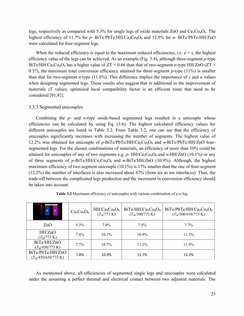
25
legs, respectively as compared with 5.3% for single legs of oxide materials ZnO and Ca3Co4O9. The
highest efficiency of 11.7% for p- BiTe/PbTe/HH/Ca3Co4O9 and 12.5% for n- BiTe/PbTe/HH/ZnO
were calculated for four-segment legs.
When the reduced efficiency is equal to the maximum reduced efficiencies, i.e. u = s, the highest
efficiency value of the legs can be achieved. As an example (Fig. 3.4), although three-segment p-type
BiTe/HH/Ca3Co4O9 has a higher value of ZT = 0.66 than that of two-segment n-type HH/ZnO (ZT =
0.57), the maximum total conversion efficiency attained for three-segment p-type (11%) is smaller
than that for two-segment n-type (11.6%). This difference implies the importance of s and u values
when designing segmented legs. These results also suggest that in additional to the improvement of
materials zT values, optimized local compatibility factor is an efficient route that need to be
considered [91,92].
3.3.3 Segmented unicouples
Combining the p- and n-type oxide-based segmented legs resulted in a unicouple whose
efficiencies can be calculated by using Eq. (3.6). The highest calculated efficiency values for
different unicouples are listed in Table 3.2. From Table 3.2, one can see that the efficiency of
unicouples significantly increases with increasing the number of segments. The highest value of
12.2% was obtained for unicouple of p-BiTe/PbTe/HH/Ca3Co4O9 and n-BiTe/PbTe/HH/ZnO four-
segmented legs. For the chosen combinations of materials, an efficiency of more than 10% could be
attained for unicouples of any of two segments e.g. p- HH/Ca3Co4O9 and n-HH/ZnO (10.1%) or any
of three segments of p-BiTe/HH/Ca3Co4O9 and n-BiTe/HH/ZnO (10.9%). Although, the highest
maximum efficiency of two-segment unicouple (10.1%) is 17% smaller than the one of four-segment
(12.2%) the number of interfaces is also increased about 67% (from six to ten interfaces). Thus, the
trade-off between the complicated legs production and the increment in conversion efficiency should
be taken into account.
Table 3.2 Maximum efficiency of unicouples with various combination of p-n leg.
As mentioned above, all efficiencies of segmented single legs and unicouples were calculated
under the assuming a perfect thermal and electrical contact between two adjusted materials. The
Ca3Co4O9 HH/Ca3Co4O9
(TM/773 K) BiTe/HH/Ca3Co4O9
(TM/500/773 K) BiTe/PbTe/HH/Ca3Co4O9
(TM/500/650/773 K)
ZnO 5.3% 7.0% 7.5% 7.7%
HH/ZnO (TM/773 K)
7.4% 10.1% 10.9% 11.3%
BiTe/HH/ZnO (TM/450/773 K)
7.7% 10.7% 11.2% 11.9%
BiTe/PbTe/HH/ZnO (TM/450/650/773 K)
7.8% 10.9% 11.7% 12.2%
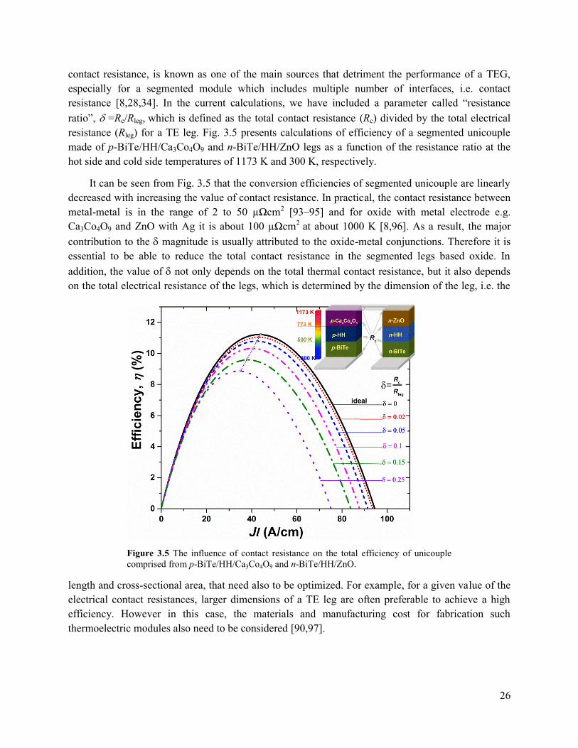
26
contact resistance, is known as one of the main sources that detriment the performance of a TEG,
especially for a segmented module which includes multiple number of interfaces, i.e. contact
resistance [8,28,34]. In the current calculations, we have included a parameter called “resistance
ratio”, =Rc/Rleg, which is defined as the total contact resistance (Rc) divided by the total electrical
resistance (Rleg) for a TE leg. Fig. 3.5 presents calculations of efficiency of a segmented unicouple
made of p-BiTe/HH/Ca3Co4O9 and n-BiTe/HH/ZnO legs as a function of the resistance ratio at the
hot side and cold side temperatures of 1173 K and 300 K, respectively.
It can be seen from Fig. 3.5 that the conversion efficiencies of segmented unicouple are linearly
decreased with increasing the value of contact resistance. In practical, the contact resistance between
metal-metal is in the range of 2 to 50 µΩcm2 [93–95] and for oxide with metal electrode e.g.
Ca3Co4O9 and ZnO with Ag it is about 100 µΩcm2 at about 1000 K [8,96]. As a result, the major
contribution to the magnitude is usually attributed to the oxide-metal conjunctions. Therefore it is
essential to be able to reduce the total contact resistance in the segmented legs based oxide. In
addition, the value of not only depends on the total thermal contact resistance, but it also depends
on the total electrical resistance of the legs, which is determined by the dimension of the leg, i.e. the
length and cross-sectional area, that need also to be optimized. For example, for a given value of the
electrical contact resistances, larger dimensions of a TE leg are often preferable to achieve a high
efficiency. However in this case, the materials and manufacturing cost for fabrication such
thermoelectric modules also need to be considered [90,97].
Figure 3.5 The influence of contact resistance on the total efficiency of unicouple
comprised from p-BiTe/HH/Ca3Co4O9 and n-BiTe/HH/ZnO.

27
3.4 Conclusions
In summary, the low-cost, high efficiency oxide-based segmented legs/unicouples have been
investigated using the numerical modelling. The materials to be segmented were selected based on
their figure-of-merit, the “efficiency ratio” and their compatibility factors. The calculated results
indicate that oxides materials are good candidates at the hot side for achieving low-cost, high
performance segmented legs/unicouples. A maximum efficiency of more than 10% could be attained
for the unicouples built up from segmented legs of p-Ca3Co4O9 and n-ZnO with intermetallic
compounds such as HH and BiTe. The modelling results have showed that in the building up TEG
based segmented legs the trade-off between the increment in conversion efficiencies and the external
factor i.e. complicated production and increasing interface contact resistances and should be taken
into consideration. The obtained results suggest a tool to construct low-cost and high efficiency
thermoelectric modules based on oxide materials for high-temperature power generation.
28
Chapter 4 High-temperature thermoelectric properties of Ca0.9Y0.1Mn1-xFexO3
(0 ≤ x ≤ 0.25)
With the aim of the thesis is to develop low-cost, high-temperature TEG based oxide materials
through the investigation in the Chapter 3 pointed out that the p- type nanocomposite Ca3Co4O9 and
the n-type doped ZnO materials are selected as the best candidates. The modules construction will be
then used the oxide materials which are cooperated with two separate projects on development and
processing of n-type, p-type oxide thermoelectric materials. The results have been published
elsewhere [44,46,61,98]. As reported in the literature, so far, the studies indicated that n-type
materials, such as ZnO, SrTiO3, have much lower thermoelectric performance than their p-type
counterparts. Therefore, in this chapter, the study of n-type of Ca0.9Y0.1Mn1-xFexO3 is chosen as an
alternative n-type oxide.
Abstract
Polycrystalline compounds of Ca0.9Y0.1Mn1-xFexO3 for 0 ≤ x ≤ 0.25 were prepared by solid-state
reaction, followed by spark plasma sintering (SPS) process, and their thermoelectric properties from
300 to 1200 K were systematically investigated in term of Y and Fe co-doping at the Ca- and Mn-
sites, respectively. Crystal structure refinement revealed that all the investigated samples have the O-
type orthorhombic structure, and the lattice parameters slightly increased with increasing Fe
concentration, causing a crystal distortion. It was found that with increasing the content of Fe doping,
the Seebeck coefficient of Ca0.9Y0.1Mn1-xFexO3 tended to increase, while the tendency towards the
electrical conductivity was more complicated. The highest power factor was found to be 2.1 x10⁻⁴
W/mK2 at 1150 K for the sample with x = 0.05 after annealing at 1523 K for 24 h in air. Thermal
conductivity of the Fe-doped samples showed a lower value than that of the x = 0 sample, and the
highest dimensionless figure-of-merit, zT was found to be improved about 20% for the sample with x
= 0.05 as compared to that of the x = 0 sample at 1150 K.
The work discussed in this chapter is published in: Le Thanh Hung, Ngo Van Nong, Li Han, Dang Le
Minh, Kasper A Borup, Bo B. Iversen, Nini Pryds, Søren Linderoth, “High-temperature
Thermoelectric Properties of Ca0.9Y0.1Mn1-xFexO3 (0 ≤ x ≤ 0.25)”, J. Mater. Sci. 48, 2817 (2013).
[45].

29
4.1 Introduction
With increasing the global energy demand, thermoelectric materials have recently gained much
interest in both the theoretical and technological aspects due to the potential use of these materials in
converting waste heat into electricity [3,99]. In general, for a single thermoelectric material the
conversion efficiency can be evaluated by the dimensionless figure-of-merit (zT = S2T/, where ,
S, T, are the electrical conductivity, the Seebeck coefficient, the absolute temperature, and the
thermal conductivity, respectively). The requirements for practical application of high thermal-to-
electrical energy conversion place on finding suitable thermoelectric materials, and are not easily
satisfied. They should not only possess good thermoelectric performance, they must also be stable at
high temperatures and be composed of nontoxic and low-cost elements, but also must be able to be
processed and shaped cheaply. For this purpose, metal oxide-based materials are considered as good
candidates.
CaMnO3, which is a perovskite oxide with orthorhombic structure at room temperature, has also
been considered as a promising thermoelectric n-type material for high-temperature application
[88,100–105]. Many attempts have been made in order to improve the thermoelectric performance of
this type of material, mainly to enhance the electrical conductivity, reduce further the thermal
conductivity, while avoiding degradation of the Seebeck coefficient. Most of these studies have been
focused on doping for example Yb at Ca-site [88,100–103] or Nb at Mn-site [88,104], while only few
reports performed the research on dually doping e.g. Sr and Yb at Ca-site [105]. Previous reports
have showed that the substitution of Y for Ca resulted in a significant improvement in the
thermoelectric performance of Ca1-xYxMnO3 system in a wide temperature region, and the optimum
doping level was found to be around x = 0.1 [101,106]. Similar to other multi-valence systems such
as cobaltites [44] or titanates [107], the interrelation between Mn3+ and Mn4+ should be responsible
for the transport mechanism in the CaMnO3 material. Therefore, doping of trivalent ions such as Fe3+
or Co3+ at the Mn-site would probably influence the transport properties of this material.
In this chapter, we have prepared the Ca0.9Y0.1Mn1-xFexO3 system with 0 ≤ x ≤ 0.25, in which Ca-
site was substituted with Y at a fixed concentration and Mn-site was partly replaced by Fe. The
structural and the thermoelectric properties of these set of materials were investigated in detail. The
influence of Y and Fe doping at Ca- and Mn-sites, respectively, on the crystal structure was carefully
studied by the Rietveld refinement analysis. The correlation between the crystal structures and the
thermoelectric properties are discussed.
4.2 Experimental
Polycrystalline samples of Ca0.9Y0.1Mn1-xFexO3 with x = 0, 0.05, 0.15, 0.2, and 0.25 were
synthesized by a solid-state reaction. A mixture of commercially available CaCO3 (98 %), MnO2
(99.9 %), Fe2O3 (99.9 %), and Y2O3 (99.9%) precursors were thoroughly mixed by ball milling with
ethanol for 24 h. The mixtures were dried, and then calcined at 1273 K for 24 h in air with an
intermediate grinding procedure. The densify processing was carried out using a spark plasma
sintering (SPS) system (SPS Syntex Inc., Japan). The samples were heated to 1123 K, while a

30
uniaxial pressure of 50 MPa was applied for 8 min in Ar atmosphere. During the experiment, the
temperature, applied pressure, and displacement of the sample were recorded continuously. The as-
prepared samples were then polished in order to remove the graphite foil used during the SPS
processing. The pellets were then cut into bar (3.5 × 3.5 × 12 mm3) and plate (10 × 10 × 1.4 mm3)
shapes for the thermoelectric properties and thermal conductivity measurements, respectively. XRD
analysis was carried out on the powders after calcining and after the SPS processing using a Bruker
robot diffractometer with Cu Kα radiation. Structural refinement was carried out using the Rietveld
method with TOPAS 4.1. Microstructures of the samples were observed using scanning electron
microscopy (SEM) with a Hitachi TM-1000 system. The electrical resistivity and the Seebeck
coefficient were measured simultaneously from room temperature to 1200 K using an ULVAC-
RIKO ZEM3 measurement system in a low-pressure helium atmosphere. The thermal conductivity,
κ, was determined from the measured thermal diffusivity, , the heat capacity, Cp, and the density, d,
using the formula: κ = d Cp. The densities of the samples were measured by an AccuPyc-1340
pycnometer. The thermal diffusivity was measured by a LFA-457 laser flash system.
4.3 Results and discussion
Figure 4.1 shows powder X-ray diffraction (XRD) spectra measured at room temperature for pure
CaMnO3 and for Ca0.9Y0.1Mn1-xFexO3 samples with x = 0, 0.05, 0.1, 0.15, 0.2, and 0.25 after they
were calcined at 1273 K for 24 h in air. All the visible XRD peaks can be indexed as the pure phase
of CaMnO3, indicating that all the investigated samples are single phase.
Figure 4.1 X-ray diffraction patterns of CaMnO3 and Ca0.9Y0.1Mn1-xFexO3 with x = 0,
0.05, 0.1, 0.15, 0.2, 0.25 samples after calcining at 1273 K for 24 h in air.

31
Figure 4.2 displays XRD patterns of a typical sample with x = 0.05 for the calcined powder (a), SPS
sintered pellet (b), and the SPS sample after further heat treatment at 1523 K for 24 h in air (c). As
indicated by this figure regardless of heat treatment, the structure remained the same. The structure
refinement for the calcined powders Ca0.9Y0.1Mn1-xFexO3 system was conducted using Topas 4.1
Rietveld refinement software with input parameters which were taken from Poeppelmeier et al. [108]
using space group Pnma (No.62), and the refined results are summarized in Table 4.1. The profile R
value (Rp), weighted profile R-factor (Rwp), and Goodness of fit (GOF) values obtained in this
analysis are of high quality, and is clearly illustrated in Fig. 4.2 for a typical Ca0.9Y0.1Mn1-xFexO3
sample with x = 0.05 as an example. This result implies that Y and Fe most likely substituted on the
Ca- and Mn-sites of CaMnO3, respectively. It can be judged from the data in Table 4.1, that the
lattice parameters follow a relation of 𝑐/√2 ≤ 𝑎 ≤ 𝑏, confirming that the polycrystalline compounds
Ca0.9Y0.1Mn1-xFexO3 of our samples have O-type orthorhombic structure [105,109].
The dependence of the lattice parameters and the cell volumes of Ca0.9Y0.1Mn1-xFexO3 on the
amount of Fe substituent are presented in Fig. 4.3. The result shows that the lattice parameters
slightly increased with the increasing Fe concentration, resulting in an expansion in the unit cell
volume. The increase in lattice parameters may be associated with the substitution of Fe3+ with a
larger ionic radius (0.55 Å) for smaller Mn4+ (0.53 Å) ion [110].
Figure 4.2 X-ray diffraction patterns of a typical sample Ca0.9Y0.1Mn0.95Fe0.05O3: (a) Rietveld
refinement profile of the calcined powder, (b) pellet sample sintered by SPS at 1173 K under pressure
50 MPa for 8 minutes under Ar atmosphere, (c) SPS sample after annealing at 1523 K in air for 24 h.

32
In the case if Fe3+ substitutes for Mn3+ (0.58 Å), which has larger ionic radius, one would expect a
slight contraction of the unit cell volume. The geometric distortion of ABO3-type perovskites can be
explained by Goldsmith tolerance factor, which is defined as
𝑡 = (𝑟𝐴 + 𝑟𝑂)/√2(𝑟𝐵 + 𝑟𝑂) (4.1)
where rA, rB and rO are the ionic radii of A, B, and O atoms, respectively [110]. For Ca0.9Y0.1Mn1-
xFexO3 compounds, calculation of Goldsmith tolerance factors (t) showed that the highest t value was
0.988 in the case of Fe3+ substitutes for Mn4+ and the smallest t value was 0.963 with Fe3+ substitutes
for Mn3+. It implies that the orthorhombic structure is stable for all Ca0.9Y0.1Mn1-xFexO3 compounds.
Figure 4.4 depicts the temperature dependence of the electrical conductivity for Ca0.9Y0.1Mn1-
xFexO3 with x = 0, 0.05, 0.1, 0.15, 0.2, and 0.25 SPS sintered samples. The result points out that the
electrical conductivity of the entire samples exhibit a semiconducting-like behavior over the whole
measured temperature range. However, the electrical conductivity of the SPS sintered samples does
Compositions (x) 0 0.05 0.1 0.15 0.2 0.25
Rwp(%) 8.42 9.33 9.39 11.27 10.62 10.62
Rp(%) 6.68 6.70 6.42 7.67 7.45 6.63
GOF 1.73 1.90 1.71 1.83 1.92 1.85
a (Å) 5.28233(2) 5.27480(3) 5.3018(3) 5.3004(1) 5.29596(2) 5.29999(3)
b (Å) 7.46185(3) 7.45797(4) 7.4846(6) 7.4806(2) 7.48990(3) 7.49067(5)
c (Å) 5.26841(2) 5.27498(5) 5.2899(2) 5.3035(3) 5.28405(2) 5.28344(3)
V (Å3) 207.659(2) 207.514(2) 209.914(2) 210.284(3) 209.598(3) 209.755(2)
Table 4.1 Structural refinement factors, lattice parameters and cell volumes of Ca0.9Y0.1Mn1-xFexO3.
Figure 4.3 Lattice parameters and cell volume of Ca0.9Y0.1Mn1-
xFexO3 as function of Fe content (x).

33
not show a clear tendency with the increase
of Fe doping concentration. The value of
tends to decrease with increasing Fe
concentration for x > 0.1, while 𝜎 increases
for the samples with x 0.1. It should be
noted here that those samples were sintered
under a high pressure at high temperature,
and in inert gas atmosphere. The oxygen
content or even the microstructure may be
varied from the samples, causing the
different behaviors of the electrical
conductivity as a result.
Temperature dependence of the Seebeck
coefficient (S) for the SPS sintered samples
of Ca0.9Y0.1Mn1-xFexO3 with x = 0, 0.05, 0.1,
0.15, 0.2, and 0.25 are shown in Fig.4.5. S of
all investigated samples show a negative
values over the whole measured temperature
range, indicating n-type conduction.
Contrastingly to the electrical conductivity,
the absolute S values increase with
increasing Fe concentration, and the effect
was more substantial in low temperature
region.
In order to understand further the
influence of the Fe doping on the
thermoelectric properties, four SPS samples
with x = 0, 0.05, 0.1, and 0.15 were selected
and further annealed at 1523 K for 24 h in
air. Figure 4.6a shows the electrical
conductivity and the Seebeck coefficient as a
function of temperature after annealing at
1523 K for 24 h in air. As seen from Fig.
4.6a a clear tendency showing the decrease
of , while S increases with increasing Fe concentration from x = 0, 0.05, 0.1 to 0.15. The value of
electrical conductivity was found to increase with more than two times as compared with post
samples, while the Seebeck coefficient remained almost the same.
In general, the conduction mechanism of CaMnO3 can be interpreted by hopping conduction [111]
where hopping of the charge carriers is thermally activated with the activation energy Ea, the
temperature dependence of the electrical conductivity 𝜎 is given as
Figure 4.4 Temperature dependence of the electrical
conductivity for Ca0.9Y0.1Mn1-xFexO3 with x = 0, 0.05, 0.1,
0.15, 0.2, 0.25 SPS sintered samples; Inset, the activation
energies were fitted from experimental data.
Figure 4.5 Temperature dependence of the Seebeck
coefficient for Ca0.9Y0.1Mn1-xFexO3 with x = 0, 0.05, 0.1,
0.15, 0.2, and 0.25 SPS sintered samples.

34
𝜎 = C/T exp(-Ea/kBT) (4.2)
where T is absolute temperature, kB is the Boltzmann constant, and C is a constant depending on the
charge carrier concentration. The activation energy could be estimated from the Arrhenius plot of
Ln𝜎T versus 1/T as shown in the inset in Fig. 4.4.
The calculated activation energy, Ea is listed in Table 4.2 for all investigated samples, showing
that Ea is linearly increasing with the increase of Fe substituent. However, the relationship between 𝜎
and Ea is only obeyed the hopping conduction’s equation at temperatures below 700 K, as shown in
Fig. 4.4 inset as well as in Table 4.2. As for the x = 0 and 0.05 samples, the Ln𝜎T versus 1/T curve
showed two different slopes in the temperature regions of T < 700 and T > 700 yielding two activate
energies (see Table 4.2), which is similar to the observation by Vecherskii et al. [112] on the oxygen
non-stoichiometry CaMnO3- system.
Table 4.2 Relative densities and electrical characteristics of Ca0.9Y0.1Mn1-xFexO3.
Compositions
(x) 0 0.05 0.1 0.15 0.2 0.25
Relative
density (%) 94.36 94.86 97.40 96.65 95.60 93.39
Ea (meV) 117.46 146.15 155.28 181.33 189.69 227.47
For an extrinsic n-type semiconductor with negligible hole conduction, the thermoelectric power can
be given by [18, 19]:
Figure 4.6 Temperature dependence of (a) the Seebeck coefficient (solid symbols) and the electrical conductivity
(open symbols), and (b) the power factors for all the SPS sintered samples Ca0.9Y0.1Mn1-xFexO3 with x = 0, 0.05, 0.1,
0.15, 0.2, 0.25 and selective samples with x = 0, 0.05, 0.1, 0.15 after annealing annealed at 1523 K for 24 h in air.
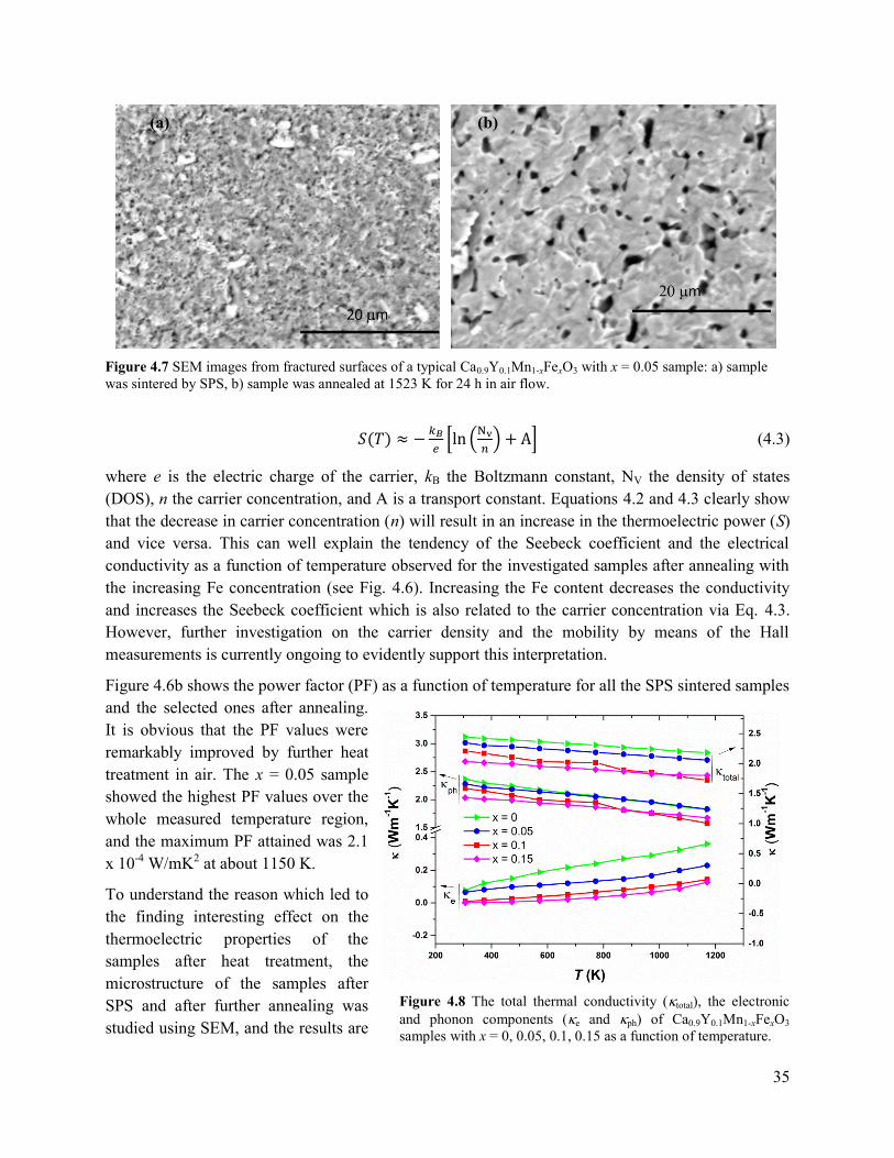
35
𝑆(𝑇) ≈ −𝑘𝐵
𝑒[ln (
Nv
𝑛) + A] (4.3)
where e is the electric charge of the carrier, kB the Boltzmann constant, NV the density of states
(DOS), n the carrier concentration, and A is a transport constant. Equations 4.2 and 4.3 clearly show
that the decrease in carrier concentration (n) will result in an increase in the thermoelectric power (S)
and vice versa. This can well explain the tendency of the Seebeck coefficient and the electrical
conductivity as a function of temperature observed for the investigated samples after annealing with
the increasing Fe concentration (see Fig. 4.6). Increasing the Fe content decreases the conductivity
and increases the Seebeck coefficient which is also related to the carrier concentration via Eq. 4.3.
However, further investigation on the carrier density and the mobility by means of the Hall
measurements is currently ongoing to evidently support this interpretation.
Figure 4.6b shows the power factor (PF) as a function of temperature for all the SPS sintered samples
and the selected ones after annealing.
It is obvious that the PF values were
remarkably improved by further heat
treatment in air. The x = 0.05 sample
showed the highest PF values over the
whole measured temperature region,
and the maximum PF attained was 2.1
x 10-4 W/mK2 at about 1150 K.
To understand the reason which led to
the finding interesting effect on the
thermoelectric properties of the
samples after heat treatment, the
microstructure of the samples after
SPS and after further annealing was
studied using SEM, and the results are
Figure 4.7 SEM images from fractured surfaces of a typical Ca0.9Y0.1Mn1-xFexO3 with x = 0.05 sample: a) sample
was sintered by SPS, b) sample was annealed at 1523 K for 24 h in air flow.
(a) (b)
Figure 4.8 The total thermal conductivity (total), the electronic
and phonon components (e and ph) of Ca0.9Y0.1Mn1-xFexO3
samples with x = 0, 0.05, 0.1, 0.15 as a function of temperature.
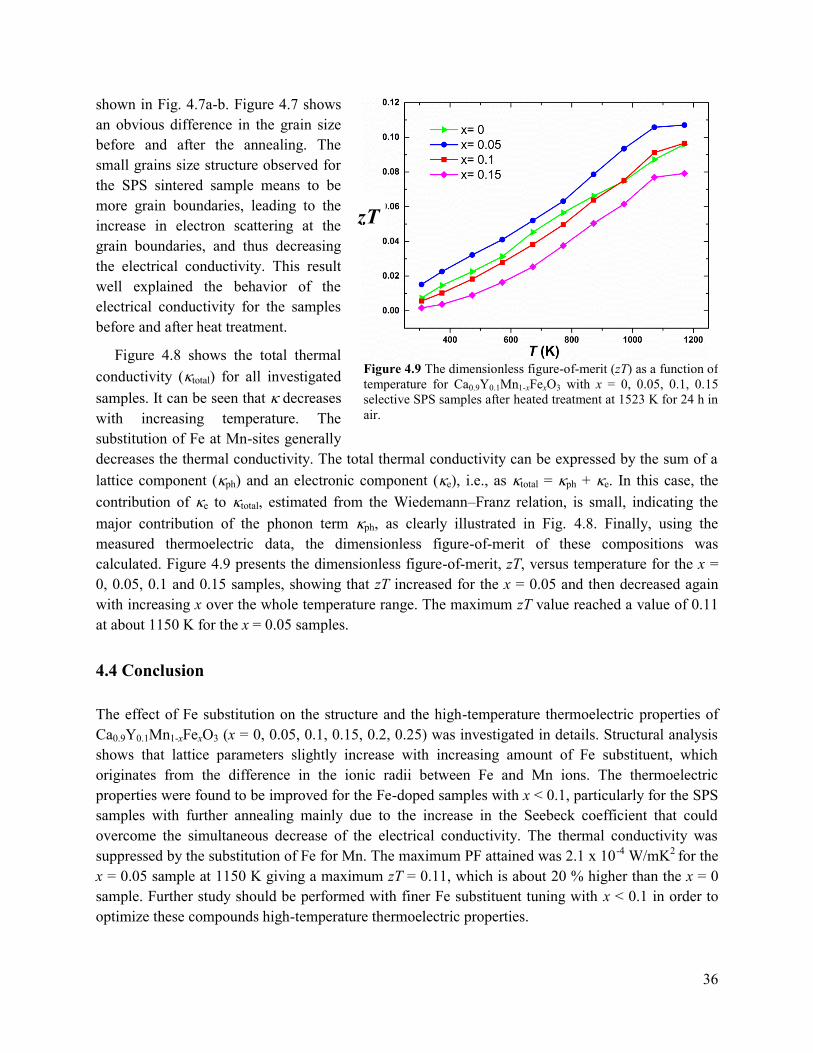
36
shown in Fig. 4.7a-b. Figure 4.7 shows
an obvious difference in the grain size
before and after the annealing. The
small grains size structure observed for
the SPS sintered sample means to be
more grain boundaries, leading to the
increase in electron scattering at the
grain boundaries, and thus decreasing
the electrical conductivity. This result
well explained the behavior of the
electrical conductivity for the samples
before and after heat treatment.
Figure 4.8 shows the total thermal
conductivity (total) for all investigated
samples. It can be seen that decreases
with increasing temperature. The
substitution of Fe at Mn-sites generally
decreases the thermal conductivity. The total thermal conductivity can be expressed by the sum of a
lattice component (ph) and an electronic component (e), i.e., as total = ph + e. In this case, the
contribution of e to total, estimated from the Wiedemann–Franz relation, is small, indicating the
major contribution of the phonon term ph, as clearly illustrated in Fig. 4.8. Finally, using the
measured thermoelectric data, the dimensionless figure-of-merit of these compositions was
calculated. Figure 4.9 presents the dimensionless figure-of-merit, zT, versus temperature for the x =
0, 0.05, 0.1 and 0.15 samples, showing that zT increased for the x = 0.05 and then decreased again
with increasing x over the whole temperature range. The maximum zT value reached a value of 0.11
at about 1150 K for the x = 0.05 samples.
4.4 Conclusion
The effect of Fe substitution on the structure and the high-temperature thermoelectric properties of
Ca0.9Y0.1Mn1-xFexO3 (x = 0, 0.05, 0.1, 0.15, 0.2, 0.25) was investigated in details. Structural analysis
shows that lattice parameters slightly increase with increasing amount of Fe substituent, which
originates from the difference in the ionic radii between Fe and Mn ions. The thermoelectric
properties were found to be improved for the Fe-doped samples with x < 0.1, particularly for the SPS
samples with further annealing mainly due to the increase in the Seebeck coefficient that could
overcome the simultaneous decrease of the electrical conductivity. The thermal conductivity was
suppressed by the substitution of Fe for Mn. The maximum PF attained was 2.1 x 10⁻⁴ W/mK2 for the
x = 0.05 sample at 1150 K giving a maximum zT = 0.11, which is about 20 % higher than the x = 0
sample. Further study should be performed with finer Fe substituent tuning with x < 0.1 in order to
optimize these compounds high-temperature thermoelectric properties.
Figure 4.9 The dimensionless figure-of-merit (zT) as a function of
temperature for Ca0.9Y0.1Mn1-xFexO3 with x = 0, 0.05, 0.1, 0.15
selective SPS samples after heated treatment at 1523 K for 24 h in
air.
zT

37
Chapter 5 Segmented thermoelectric oxide-based module
Abstract
To improve the thermoelectric (TE) power generation performance of an oxide-based module, a
segmentation of the legs is implemented. A high-performance segmented oxide-based TE module
using segmentation of the half-Heusler Ti0.3Zr0.35Hf0.35CoSb0.8Sn0.2 and the misfit-layered cobaltate
Ca3Co4O9+ as the p-leg and 2% Al-doped ZnO as the n-leg was for the first time fabricated and
characterized. The TE properties of individual legs as well as the interfacial contact resistances as a
function of temperature were investigated. Numerical modeling was used to predict the efficiency
and to evaluate the influence of the electrical and thermal losses on the performance of TE
modules. The maximum output power of a 4-couples segmented module at a temperature
difference of about 700 K attained 829 mW corresponding to a power density of 650 mW/cm2,
which is three times higher than that of the best reported non-segmented oxide module under the
same condition. Initial long-term stability test of the module at hot and cold side temperatures of
1073/444 K showed a promising result although a slightly degradation tendency could be observed
after 48 h operating in air.
The work presented in this chapter is submitted to Energy 2014: Le Thanh Hung, Ngo Van Nong,
Gerald Jeffrey Snyder, Benjamin Balke, Li Han, Rasmus Bjørk, Pham Hoang Ngan, Tim C. Holgate,
Søren Linderoth, and Nini Pryds, “Segmented thermoelectric oxide-based module”. Under review
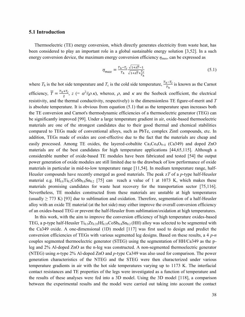
38
5.1 Introduction
Thermoelectric (TE) energy conversion, which directly generates electricity from waste heat, has
been considered to play an important role in a global sustainable energy solution [3,52]. In a such
energy conversion device, the maximum energy conversion efficiency ηmax, can be expressed as
𝑚𝑎𝑥
=𝑇ℎ−𝑇𝑐
𝑇ℎ
√1+𝑧𝑇−1
√1+𝑧𝑇+𝑇𝑐𝑇ℎ
(5.1)
where Th is the hot side temperature and Tc is the cold side temperature, 𝑇ℎ−𝑇𝑐
𝑇ℎ is known as the Carnot
efficiency, 𝑇 =𝑇ℎ+𝑇𝑐
2, z (= 2/(.), where, , and are the Seebeck coefficient, the electrical
resistivity, and the thermal conductivity, respectively) is the dimensionless TE figure-of-merit and T
is absolute temperature. It is obvious from equation (5.1) that as the temperature span increases both
the TE conversion and Carnot's thermodynamic efficiencies of a thermoelectric generator (TEG) can
be significantly improved [99]. Under a large temperature gradient in air, oxide-based thermoelectric
materials are one of the strongest candidates due to their good thermal and chemical stabilities
compared to TEGs made of conventional alloys, such as PbTe, complex Zintl compounds, etc. In
addition, TEGs made of oxides are cost-effective due to the fact that the materials are cheap and
easily processed. Among TE oxides, the layered-cobaltite Ca3Co4O9+ (Ca349) and doped ZnO
materials are of the best candidates for high temperature applications [44,65,115]. Although a
considerable number of oxide-based TE modules have been fabricated and tested [54] the output
power generation of oxide modules are still limited due to the drawback of low performance of oxide
materials in particular in mid-to-low temperature range [11,54]. In medium temperature range, half-
Heusler compounds have recently emerged as good materials. The peak zT of a p-type half-Heusler
material e.g. Hf0.8Ti0.2CoSb0.8Sn0.2 [75] can reach a value of 1 at 1073 K, which makes these
materials promising candidates for waste heat recovery for the transportation sector [75,116].
Nevertheless, TE modules constructed from these materials are unstable at high temperatures
(usually ≥ 773 K) [93] due to sublimation and oxidation. Therefore, segmentation of a half-Heusler
alloy with an oxide TE material (at the hot side) may either improve the overall conversion efficiency
of an oxides-based TEG or prevent the half-Heusler from sublimation/oxidation at high temperatures.
In this work, with the aim to improve the conversion efficiency of high temperature oxides-based
TEG, a p-type half-Heusler Ti0.3Zr0.35Hf0.35CoSb0.8Sn0.2 (HH) alloy was selected to be segmented with
the Ca349 oxide. A one-dimensional (1D) model [117] was first used to design and predict the
conversion efficiencies of TEGs with various segmented leg designs. Based on these results, a 4 p-n
couples segmented thermoelectric generator (STEG) using the segmentation of HH/Ca349 as the p-
leg and 2% Al-doped ZnO as the n-leg was constructed. A non-segmented thermoelectric generator
(NTEG) using n-type 2% Al-doped ZnO and p-type Ca349 was also used for comparison. The power
generation characteristics of the NTEG and the STEG were then characterized under various
temperature gradients in air with the hot side temperatures varying up to 1173 K. The interfacial
contact resistances and TE properties of the legs were investigated as a function of temperature and
the results of these analyses were fed into a 3D model. Using the 3D model [118], a comparison
between the experimental results and the model were carried out taking into account the contact

39
resistances as well as other parasitic losses. In addition, a preliminary long-term test was also
performed on the STEG at high temperature to investigate the stability of the module.
5.2 Modeling
5.2.1 Formulation of the model
With the purpose of evaluating the efficiency of non-segmented and segmented TE elements, both
the 1D [26,117] and the three-dimensional 3D [118] numerical models are used. These models take
into account all thermoelectric effects i.e. the Peltier, Seebeck and Thomson effects, as well as heat
conduction, Joule heating and the temperature dependence of the resistivity (T), thermal
conductivity (T), Seebeck coefficient α(T), and compatibility factor 𝑠 =√1+𝑧𝑇−1
𝑇. To have a
guideline on the materials selection and TEG design, the efficiencies of segmented and non-
segmented TE elements were first calculated under the ideal conditions, i.e. neglecting all the heat
losses, thermal and electrical contact resistances. The calculations can therefore be considered as an
upper limit for the obtainable actual efficiency in experiments. As for a practical TEG, the
performance strongly depends on the thermal and electrical losses. Therefore, the 3D numerical
model is used to evaluate the module’s characteristics under realistic conditions including losses.
Besides using the 3D numerical model, 1D modeling was used to confirm the design of the module
geometries.
The 1D model solves for the reduced current density u (= J/κ), which is defined as the ratio
between the electrical current density (J) and the heat flux by conduction. When u is defined at a
single point – e.g. at the hot side, u (T = Th) – the value of u at any temperature along the leg can be
determined using the following the differential equation
𝑑𝑢
𝑑𝑇= 𝑢2𝑇
𝑑𝛼
𝑑𝑇+ 𝑢3𝜌𝜅, (5.2)
with an approximate recursive solution given elsewhere [99,119]. The differential equation is valid
for both non-segmented and segmented legs if – for the latter – the material properties are changed
from one material to another at a certain interface temperature (Tm) where the segments meet. From
the reduced current densities evaluated at the cold and hot side temperatures, uc = u (T = Tc) and uh =
u (T=Th), the efficiency of a segmented or non-segmented leg can be found:
𝑙𝑒𝑔
= 1 −𝛼𝑐𝑇𝑐 +
1
𝑢𝑐
𝛼ℎ𝑇ℎ + 1
𝑢ℎ
(5.3)
As for the segmented legs, leg is determined by an optimum interface temperature Tm. To simplify
the issue, Tm is often sets to be the temperature where the material at the cold side reaches its
maximum zT.
For a typical n-p unicouple, the electric current through both elements is the same, but the relative
contribution to the total heat flux is regulated by having different cross-sectional areas Ap and An
(with Ap and An being the cross-sectional areas of p- and n-type legs, respectively). The maximum
efficiency condition therefore requires a specific ratio of Ap/An to optimize the electric current of the
unicouple. Assuming the n-element and the p-element have the same total length (l = lp = ln), the

40
ratio of the cross-sectional areas can be calculated by equating the total electric current (I = JpAp = -
JnAn):
𝐴𝑝
𝐴𝑛=
−𝐽𝑛
𝐽𝑝=
− ∫ 𝑢𝑛𝑛dTTh
Tc
∫ 𝑢𝑝𝑝dTTh
Tc
(5.4)
The electric current can be solved in term of the total area (Atotal = Ap + An):
𝐼 =𝐴𝑡𝑜𝑡𝑎𝑙
𝑙
− ∫ 𝑢𝑛𝑛dTTh
Tc∫ 𝑢𝑝𝑝dT
ThTc
∫ 𝑢𝑝𝑝dTTh
Tc−∫ 𝑢𝑛𝑛dT
ThTc
(5.5)
The total voltage produced by a p-n unicouple can be computed by
𝑉 =1
𝑢ℎ,𝑝+ ℎ,𝑝𝑇ℎ −
1
𝑢𝑐,𝑝− 𝑐,𝑝𝑇𝑐 +
1
𝑢ℎ,𝑛+ ℎ,𝑛𝑇ℎ −
1
𝑢𝑐,𝑛− 𝑐,𝑛𝑇𝑐 (5.6)
The total electric power generation can then be determined by the relationship, W = IV. The total heat
flowing through the p and n legs can be expressed as
𝑈𝑡𝑜𝑡𝑎𝑙 = 𝐼(𝑝𝑇 +1
𝑢𝑝− 𝑛𝑇 −
1
𝑢𝑛) (5.7)
Finally, the thermal-to-electric energy conversion efficiency can be obtained:
=𝑊
𝑈𝑡𝑜𝑡𝑎𝑙 (5.8)
As for the 3D modeling, the software COMSOL Multiphysics was used to solve the full
thermoelectric equations on the specified geometry which includes p- and n-type legs, electrodes and
substrates. The coupled differential equations describe the electrical current density, J, and the heat
flux, JQ, as
−𝑱 = 𝜎∇𝑉 + 𝜎𝛼∇𝑇 (5.9)
𝑱𝑄 = −𝜅∇𝑇 + 𝑇𝛼𝑱 (5.10)
In the equation (5.9) for J, the first term is Ohms law, while the second describes the Seebeck effect.
In the equation (5.10) for JQ, the first term describes Fourier heat conduction, while the latter
describes the Peltier effect. Both Joule heating and the Thomson effect are included in the model.
The heat losses by conduction, convection and surface to surface radiation can also be included in the
model as well as contact resistances [118].
5.2.2 Calculation results
From the measured data of (T), (T), and α(T), the efficiencies of non and segmented legs/TEGs
can be calculated using the theoretical models described above. The materials for segmentation are
selected based on figure of merit (zT) and compatibility factors (s). Fig. 5.1 shows the calculated
results of zT, s, and absolute efficiency of non-segmented p-type HH, Ca349 and segmented
HH/Ca349 materials. The zT value was determined to be 0.2 for the p-type Ca349 at 1100 K and
0.65 for the Ti0.3Zr0.35Hf0.35CoSb0.8Sn0.2 (HH) at a temperature of 750 K as showed in Fig. 5.1a. The
results of p-type materials prepared in this study are comparable with previous works reported for
misfit-layered cobaltate Ca3Co4O9+ [44,115] and half-Heusler [75]. It can be seen from Fig. 5.1a that
the zT of Ca349 has low value in the low-medium temperature regions, where HH alloy exhibits
good zT. Therefore, the segmentation of Ca349 and HH is expected to exhibit high performance in
wide temperature range. In addition, an advantage of using oxide Ca349 at the hot side is that it can
help to protect the HH from oxidation and sublimation at high temperatures and possibly no

41
encapsulation is necessary for modules based
on segmented HH/Ca349. However, in order
to achieve higher thermal to electrical energy
conversion efficiency the compatibility
factor, s, of these materials has to be first
considered [26,35,70]. From Fig. 5.1a, one
can see that the compatibility factors of both
HH and Ca349 slightly increased with
increasing temperature, and they are within a
factor of two. This implies that the
segmented HH/Ca349 leg should provide a
higher performance at a larger working
temperature span [25]. Accordingly, the
maximum conversion efficiency of the
segmented HH/Ca349 leg could attain a
value of about 7.1%, which is about 2.5
times higher than the single material Ca349
(2.9%) - under the same hot side and cold
side temperatures of 1173/300 K (as showed
in Fig. 5.1b). The maximum efficiency of
single HH can attain a value of 6.4% at the
hot and cold side temperatures of 773/300 K.
The results point out that the main
contribution to the increasing performance of
segmented HH/Ca349 leg is attributed to the
high performace of HH in the low-mid
temperature range. Consequently, a TEG
comprising of segmented HH/Ca349 legs is
expected to achieve higher power generation in comparision with the one using non-segmented legs.
For many applications e.g. power generation from waste heat, finding the optimized
thermoelectric generation efficiency from given TE materials is a crucial step which affects extrinsic
properties such as geometry of p-n legs [120]. Fig. 5.2 displays the maximum efficiency of 4 p-n
couples of STEG and NTEG modules as a function of Ap/An ratio with fixed Tc = 300 K, Th = 1173 K
and 8 mm in length. In this calculation, we have assumed that the n-element and p-element have the
same length and Ap is varied while An is fixed at 0.16 cm2, and contact resistances are neglected. As
seen in Fig. 5.1c, the maximum efficiency of STEG increases sharply with increasing the Ap/An ratio
reaching a maximum 2.7% at Ap/An = 2.4 and then decreases slowly above this value. As for the
NTEG, the maximum efficiency attains 1.6% at Ap/An = 3.5. These results suggest that the STEG
would be able to perform a maximum efficiency, which is 170% higher than the NTEG at their
respective optimized Ap/An ratio. As seen from Fig. 5.2, a good agreement was obtained between the
1D and the 3D modeling. When combining with n-legs of Zn0.98Al0.02O, both the STEG and NTEG
have an efficiency of less than 3%. This is due to the fact that an n-Zn0.98Al0.02O leg could produce a
Figure 5.1 (a)Temperature dependences of zT and s of p-type
Ca349 and HH alloys. (b) Absolute efficiencies of p-type
Ca349, HH and segmented HH/Ca349.
42
maximum efficiency of only 0.7% under the hot and cold side temperatures of 1173/300 K. At the
ratio of Ap/An = 1, the efficiency of STEG attains 2.3%, which is about 85% of the maximum value
(2.7%) at the optimum Ap/An = 2.4. However, the total volume of TE legs with Ap/An = 1 (1.024
cm3) is only 59% of the total volume of TE legs with Ap/An = 2.4 (1.74 cm3), suggesting that the
capital cost might reduce due to the less amount of materials required. Therefore, we have chosen the
ratio of Ap/An = 1 to build up and characterize the 4 p-HH/Ca349, n-Zn0.98Al0.02O couples modules.
5.3 Experimental procedures
5.3.1 Thermoelectric materials
2%Al-doped ZnO platelets were synthesized using the nanoparticles as a seed by hydrothermal
method at 368 K for 24 h in a solution of 0.49 M Zn(CH3COO)2•H2O, 0.01 M Al(NO3)3, (Zn/Al =
98:2), 0.1 M NaOH, and 0.17 mM sodium citrate [18]. After hydrothermal process, the formed
precipitates were centrifugally washed several times with de-ionized water and ethanol, and then
dried in vacuum. Spark plasma sintering (SPS) system of Dr Sinter 515S (Syntex Inc., Japan) was
used to consolidate the samples under the following conditions: constant uniaxial pressure of 50
MPa; holding temperature of 1223 K; holding time of 8 min, Ar atmosphere, and a ramping rate of
130 K/min. The details of this work could be seen elsewhere [61].
The p-type Ca3Co4O9 were prepared by the solid state reaction followed by a spark plasma
sintering process. Powders of CaCO3 (99.99%) and Co3O4 (99.7%) were mixed, ball milled for 48 h
in ethanol. The mixture was then dried and calcined in air at 1173 K for 24 hours. The obtained
Figure 5.2 1D and 3D calculated efficiency as a function of the cross-
sectional area ratio Ap/An at Th/Tc = 1173/300 K for 4 couples of
NTEG and STEG with Zn0.98Al0.02O as n-legs.

43
calcined powders were then pressed into pellets using SPS with optimized sintering conditions under
a uniaxial pressure of 50 MPa at 1123 K for 5 min in vacuum.
HH compound samples with the stoichiometric composition of Ti0.3Zr0.35Hf0.35CoSb0.8Sn0.2 were
prepared by arc melting from the pure (99.999%) metals Ti, Zr, Hf, Co, Sb, and Sn under argon
atmosphere. In the course of the arc melting, the samples were re-melted and turned over three times
to ensure the homogeneity. The obtained ingots were milled in a high-energy ball milling station
(PM-100; Retsch, Germany) for 5 h under a protective argon atmosphere. The powder was filtered
through a 60-mesh sieve and then sintered using SPS at 1373 K for 20 min (heating/cooling rates of
50 K/min) under a pressure of 50 MPa.
Pellets of p- and n-type materials Ca3Co4O9, HH and 2% Al-doped ZnO were cut into bars of
448 mm3, which were then characterized for their thermoelectric properties and used as legs for
building modules.
5.3.2 Segmentation
To make segmentation, the obtained pellets of Ca349 and HH were cut, polished and then cleaned
with acetone, isopropyl alcohol and deionized water and finally dried with nitrogen. As designed
module can work at hot side temperature up to 1223 K with optimum interface temperature Tm = 773
K and cold side temperature 300 K, the length of Ca349 and HH was calculated to be 4 mm for each
with the negligible interface thermal resistance assumption. 150 µm thick Ag foil with a purity of
99.99% was used as the standard joining material between the HH and the Ca349 while 400 µm thick
Ag foil was used to make electrodes which coupled the n and the p-type materials. The brazing
process was conducted in vacuum using a SPS under 20 MPa at 973 K for 10 min. The TE properties
of both the p- and n-legs were also characterized after making the contacts, and the result (not shown
here) confirmed that there is no significant change during the joining process.
5.3.3 Module fabrication
For TE modules fabrication, the Ag electrodes was first fabricated on top of two alumina substrates
with the dimension of 21211 mm3 by hot-pressing at 1073 K for 2 h in air. The 21211 mm3
substrate was chosen to fit the size of the graphite die used in a SPS process. A set of 4segmented p-
legs and 4 non-segmented n-legs was attached onto these designed substrates according to the
configuration shown in Fig. 5.1c. The whole module was then placed in a graphite die and hot-
pressed at 973 K under a pressure of about 20 MPa in Ar atmosphere.
5.3.4 Characterization
Before and after sintering, the samples were examined by X-ray diffraction (XRD) on a Bruker
D8 diffractometer (Bruker, Germany) using Cu-Kα radiation. The measurements of the electrical
resistivity and the Seebeck coefficient were carried out on an ULVAC-RIKO ZEM-3 from room
temperature up to 1200 K under a low-pressure helium atmosphere. The thermal conductivity (κ) was
determined from the thermal diffusivity (γ), the mass density (ρ) and the specific heat capacity (Cp)

44
according to the equation κ = γρCp. The thermal diffusivity was obtained by the laser flash method
(Netzsch LFA-457, Germany), the mass densities of the samples were measured by Archimedes’
method using water with surfactant, and the specific heat capacity was measured using a differential
scanning calorimeter (Netzsch DSC 404C, Germany).
Figure 5.3a presents a schematic configuration used to determine the interfacial contact resistance
Rc by linear extrapolation of the resistance (R) vs. the distance of measuring probes (V0-1 to V0-4) and
subsequent subtraction of the contribution from the alloy (VII-0, VI-0) between the probe lead and the
interface. The contact resistance is actually the interface resistance, which is multiplied by the cross-
sectional area of the interface to give the area specific resistance of the interface (ASR). The
experiments were conducted in steady gas flow from 300 K to 850 K for the n-type leg of doped
ZnO/Ag and from 300 K to 1070 K for p-type leg of Ca349/Ag. Fig. 5.3b demonstrates the method
for measuring the contact resistance between the different TE materials in a segmented leg using the
ZEM-03. The contact resistance can be determined by measuring the electrical resistivity of
individual Ca349 (V1) and HH (V3) materials and the resistance across the interface of the segmented
HH/Ca349 materials (V2). By measuring the resistances of the segmented sample [V2(1,..4)] with
various cross-sectional areas A(1,..4), the ASR is then calculated from the slope of the fitted R-1/A curve
using the least-squares method.
Microstructure of the contacts and joining part were observed by a scanning electron microscopy
(SEM) TM3000.
The power generation characteristics of STEG and NTEG were performed in air using an in-house
Rig-test system. The I-V curves at different temperature gradients were automatically measured by
sweeping the load resistance using an electronic load system. The designed measurement system is
allowed to setup the measuring current range from 0 to 15 A with the minimum 1 mA step size,
while the electronic load and shunt resistance are then applied and scanned until reaching a value
closest the defined current together with measured voltage of TEG. The controlled software system
Figure 5.3 Configurations of the electrical contact resistance measurement for the non-segmented leg (a)
and the segmented leg (b).

45
was designed based on the Apache web server software (Open Source Software, OSS) which is able
to have maximum flexible setting up of required measurements such as gas control, cycling and long-
term stability tests etc. In order to define the accurate temperature gradient, three 0.5 mm N-type
thermocouples were attached on the Ag electrodes at the hot side and the cold side of module. The
thermocouple at the hot side is also used as the process variable for the PID of the heater controller.
The conditions of the measurement and their uncertainties are summarized in Table 1. The values
of uncertainty are calculated in term of the mean value divided by standard deviation. For the
maximum output power uncertainty is estimated from the uncertainties of the electric current and
voltage [121].
Table 5.1 The experimental measurement conditions and uncertainty.
Experiments Measurement conditions Uncertainty (%)
TE properties
Seebeck () Helium atmosphere 3-5
Res. () Helium atmosphere 2-5
Thermal cond. () Vacuum < 5
Contact resistance
(RC)*
Leg-electrode Air 1-3
Seg. leg HH/Ca349 Helium atmosphere 2-5
Module
NTEG
&
STEG
Temp.
Tc (< 450 K) Air 4.7
Th Air 2.3
Current (I) @ Pmax Air 0.2
Voltage VOC Air 0.1
V @ Pmax Air 1.2
Pmax Air 1.21
*The values excluded the geometric uncertainty.

46
5.4 Results and discussion
5.4.1 TE properties of the materials
Figure 5.4 shows the thermoelectric properties of a single p-type leg of HH and Ca349 as a
function of temperature. For both p-type materials, the Seebeck coefficient () increased with
increasing temperature (Fig. 5.4a). The values of Ca349 were measured to be about 150 V/K at
room temperature and 180 V/K at 1100 K. As for the HH alloys, values increased from 160 to
230 V/K as temperature increasing from room temperature to 700 K. The power factor (=2/) of
HH is about an order higher than that of Ca349. The thermoelectric properties of n-type 2% Al-
doped ZnO, the absolute Seebeck coefficient of n-type increased from about 40 V/K at room
temperature to about 170 V/K at 1150 K. The power factor of the n-type materials increased with
increasing temperature and reached a maximum value of about 1110-4 W/mK2 at 1150 K (Fig.
5.4b). The total thermal conductivity (not shown here) decreased with increasing temperature, and
the κ values was 23 and 5 W/mK at room temperature and 1150 K, respectively. The calculated zT
were determined to be 0.25 at about 1150 K. Thermoelectric properties of TE p and n-type in this
work are reproducible and in good agreement with the other reported values of the same
compositions [11,122].
5.4.2 Interfacial Contacts
In thermoelectric power generation devices, interfacial contact resistances are directly added to
the TE module’s internal resistance, thus it strongly decreases the electric current, I, and the output
power, P [30,123,124]. Therefore, the effect of contact resistance on output power cannot be
neglected and must be taken into account. In this study, the interfacial contact resistance between
Ag/Ca349, Ag/Zn0.98Al0.02O and HH/Ag/Ca349 have been characterized as a function of temperature,
the obtained results are presented in Figure .5a-c. Fig. 5.5a-b plots the temperature dependence of
Figure 5.4 Temperature dependence of the Seebeck coefficient and power factor of (a) p-type Ca349 and
Ti0.3Zr0.35Hf0.35CoSb0.8Sn0.2 and (b) n-type 2% Al-doped ZnO.

47
contact resistance between Ag electrodes with p-
Ca349 and n-Zn0.98Al0.02O. The interfacial
microstructure is shown through SEM images in
the inset-figures. It can be seen that the Ag
electrodes and the oxide materials have good
adhesion at the interface. SEM and EDS analyses
revealed that there are no obvious diffusion and
secondary phase observed in the vicinity of those
connections. Consequently, the obtained contact
resistance values were found to be around 400
µΩcm2, which are lower than the electrode using
Fe22Cr [125]. Fig. 5.5c illustrates the contact
resistance of segmented HH/Ag/Ca349. The
contact resistance tends to decrease from 170
µΩcm2 at room temperature to 100 µΩcm2 at
1000 K. Measurement of contact resistance of
the interface between HH and Ag electrode at
room temperature showed that the contact
resistance was as small as 5 µΩcm2. Therefore,
the main contribution to the total contact
resistance of the HH/Ca349 segment could be
attributed to the contacts of the Ca349 with Ag.
It can also be observed in Fig. 5.5c that the
interfacial resistance exhibited an abrupt change
in their temperature dependences at about 600 K.
It might be associated with a first-order
transition of Ca3Co4O9+ [125].
5.4.3 Power generation characteristics of the
modules
The power generation of module is expected to
improve by using segmented legs as predicted in
the modeling part. However, in a realistic working
condition there are many factors which effect the
output power of modules such as heat losses,
contact resistances, heat transfer, etc. In order to
demonstrate the influence of segmentation in
TEG, two type of 4 p-n couples modules STEG
(p-segmented HH/Ca349, n-2% Al-doped ZnO) and NTEG (p- pure Ca349 and 2% Al-doped ZnO as
n-legs) were prepared, tested and compared. Figure 5.6a-b shows the power generation
characteristics of NTEG and STEG at various applied temperature gradients. As expected, both
voltage-current V (I) and output power-current P (I) show the same tendency of increasing value as
Figure 5.5 (a) Contact resistance of, Ag electrode
with Ca349, (b) Ag electrode with 2% Al doped ZnO,
(c) the contact resistance of HH/Ag/Ca349 was
extracted from sandwich structure and single
component Ca349 and HH.

48
the temperature increases. At the highest applied temperature difference (Th/T
c = 1173 K/473 K),
T 700 K, the measured open circuit voltage (VOC) of the NTEG was found to be 677 mV, and the
voltage decreased linearly with increasing current. The measured maximum output power reached a
value of 256 mW at a current of 742 mA and a voltage of 345 mV (Fig. 5.6a). As for the STEG, the
measured maximum output power attained 829 mW at T 700 K which is three times higher than
that of NTEG.
In order to understand the sources that influence on the obtained experimental results, we have
conducted theoretical calculations of the power generation characteristics of the TEGs under ideal
conditions i.e. no heat losses or contact resistances (electrical or thermal). The relationship between
the open-circuit voltage VOC and the Seebeck coefficients of the TE materials forming the module
can be then expressed as [7]:
VOC = n ∫ p(T) − n(T)dTTh
Tc (5.11)
where Th and Tc are the hot and the cold side temperatures, n is the number of p-n couples, p and n
are the Seebeck coefficients of p- and n-type legs, respectively. One should note that, the
thermocouples used to measure the temperature were placed on surface of Ag electrodes and their
thermal contact resistance was assumed to be small. Therefore, the VOC values measured are well
reflecting the actual temperature span across the TE legs. At a temperature gradient of about 700 K,
the calculated VOC for non-segmented TEG was 685 mV, which is very close to the experimental
value of 677 mV.
As for the STEG, formula (11) can be rewritten as:
VOC = 𝑛 ∫ 𝐶𝑎349(𝑇)dTTℎ
T𝑚+ 𝑛 ∫ 𝐻𝐻(𝑇)dT
Tm
T𝑐− 𝑛 ∫ n(T)dT
Tℎ
T𝑐 (5.12)
Where Tm is the temperature at the connection junction. The Tm can be determined by the continuity
of the heat flux at the junction, which yields [126]:
Ca349(Th − Tm) + Ca349TI = HH(Tm − Tc) + HHTI (5.13)
In case of the open circuit voltage the Tm can be obtained by:
Tm =Ca349Th+HHTc
Ca349+HH (5.14)
The Tm was found to be 735 K, and the calculated VOC of segmented was 768 mV which is slightly
Figure 5.6 Voltages and output power for the 4 p-n couples NTEG (a) and STEG (b) as a function of current under
different temperature gradient.

49
higher than the measured value 765.7 mV. At the same temperature difference, T 700 K, the
measured VOC of STEG is 100 mV larger than the VOC of NTEG indicating that the voltage of TEG is
improved by using HH segmentation.
The magnitude of the output current, I, is proportional to the sum of the internal resistances of the
module Rint and the external resistive load RLoad and it is given by [7]:
I =VOC
Rint+RLoad (5.15)
where Rint = Rlegs + RC is the sum of the resistances of the p-n legs without metal electrodes Rlegs and
the total contact resistance RC, which includes the contact resistances at the joining part of segmented
leg, the hot-side junction and the cold-side junction.
The power output of the module as a function of VOC and the total resistance is given by
P = I2RLoad = VOC2 [
RLoad
(Rint+RLoad)2] (5.16)
It is clear from Eq. (5.11), (5.12), (5.15) and (5.16) that the power output of the module is dependent
on the Seebeck coefficient, the internal resistance and the external load resistance. The maximum
power output (PMax) occurs when the external load resistance is equal to the internal resistance. To
generate a thermoelectric module at its maximum power output, the load resistance needs to be
continuously adjusted to match the internal module resistance.
𝑃𝑀𝑎𝑥 =𝑉𝑂𝐶
2
4𝑅𝑖𝑛𝑡 (5.17)
This resistance can vary greatly with temperature due to the temperature dependences of the
resistivity of the TE materials itself as well as the temperature dependence of the total contact
resistances. It is obvious that the smaller the internal resistance, the higher the maximum output
power can be obtained.
In order to give a quantitative evaluation to the results, the internal resistances of the modules
(Rint) were also calculated from the slope of the fitted I-V curve using the least-squares method. The
obtained result shows that at a T 700 K, the Rint of the NTEG and STEG were found to be
approximately 447 and 177 m, respectively. Since the electrical resistivity of the HH is much lower
than the Ca349 in the temperature range of 473 K to 735 K, the total Rlegs of the STEG (135 m) was
subsequently reduced by 65% as compared to the NTEG (199 m). When combining the higher
Seebeck coefficient and lower internal electrical resistance, the maximum output power of the STEG
attained a value of 829 mW, which is about three times higher than that of the NTEG counterpart, as
clearly shown in Fig. 5.7a.
At T 700 K, the power density (maximum power output divided by the total area of the TE
legs) attained about 650 mW/cm2, which is higher than any reported values of the high temperature
oxide modules (see Table 5.2). In order to have a fair comparison in Table 5.2, only the modules
comprising of at least 4 p-n couples were selected. The power density can also be expressed as output
power divided by the total area of the module; in this case, the value is 200 mW/cm2 for our STEG.
However, in the literature ones often do not report the actual dimension of their modules, making it
difficult to compare the results. The obtained results indicate the advantages of using STEG for
effective power generation from waste heat recovery where the required device has to work at a high
temperature and in oxidizing conditions.

50
Table 5.2 The power generation characteristics of oxide-based thermoelectric modules reported in literatures.
In practical applications, the contact resistances (electrical and thermal contact resistances) and
the heat losses (radiation, convection and conduction) are strongly influence on the modules
performance, particularly under operation in air and at high temperature [14,30,124,128–130].
Therefore, 3D numerical modeling was used to evaluate the effects of these losses on the
performance of STEG and NTEG [118]. The efficiency as a function of current has been calculated
for different cases and the results are also given in Fig. 5.7b. The maximum calculated efficiencies
including heat losses and contact resistances were found to be 1.16% for the STEG and 0.37% for the
NTEG. The model provides the opportunity to study the influence of the contact resistance as well as
the heat loss on the efficiency. For the STEG without contact resistance the model predicated an
efficiency of 1.51%, while excluding contact resistance and heat loss the efficiency can be as high as
Ref. Year Materials No. p-n
couples
Jointing
technique
Thot
(K)
ΔT
(K)
V0
(V)
Pmax
(mW)
Legs-
size
(mm)
Power
Density
(mW/cm2)
[13] 2001
p-Ca2.7Bi0.3Co4O9
n-
Ca0.92La0.08MnO3
8 Pt paste 773 390 0.9 63.5 33 44.1
[14] 2006 p-Ca2.7Bi0.3Co4O9
n-La0.9Bi0.1NiO3 140 Ag paste 1072 551 4.5 150
1.31.3
5 31.7
[5] 2006 p-NaCo2O4
n-Zn0.98Al0.02O 12
Diffusion
welding 839 462 0.8 58 3410 20.1
[16] 2006
p-Ca2.7Bi0.3Co4O9
n-
CaMn0.98Mo0.02O3
8 Ag paste 897 565 1 170 554.5 42.5
[7] 2007 p-NaCo2O4
n-Zn0.98Al0.02O 12
Diffusion
welding 934 455 0.8 52.5 3410 18.2
[17] 2007
p-Ca2.7Bi0.3Co4O9
n-
CaMn0.98Mo0.02O3
8 Ag 1273 975 0.7 340 554.5 85
[18] 2011 p-Ca3Co4O9
n-(ZnO)7In2O3 44 Ag paste 1100 673 1.8 423 1515 27 2.1
[127
] 2013
p-
Ca2.76Cu0.24Co4O9
n-Ca0.8Dy0.2MnO3
4 Ag paste 937 321 0.2
8 31 79 25 6.2
[9] 2014 p-Ca3Co4O9
n-Zn0.98Al0.02O 6 Ag 773 248 0.12 2.26 4410 1.2
This work
p-Ca3Co4O9
n-Zn0.98Al0.02O 4 Ag
117
3 700 0.67 256 448 200
p-HH/Ca3Co4O9
n-Zn0.98Al0.02O 4 Ag
117
3 700 0.76 829 448 650

51
1.80%. From, these results it is clear that the
overall efficiency of the STEG is reduced due
to the combined effect caused by the contact
resistances and the heat loss. This illustrates
the need for reducing the contact resistance
and the heat losses in TEG in general and in
these modules in particular.
Besides the high output performance, the
long-term stability also plays a very
important role in the practical application.
Figure 5.8 exhibits the initial long-term
stability test of our STEG, which was
conducted in air while maintaining the hot
side at 1073 K and the cold side at 444 K.
These results revealed that the output power
of the module was relatively stable in air up
to 48 hours with a slight degradation rate of approximately 0.5 mW/h. After 48 h, the maximum
output power of STEG was degraded about 4%. The decreasing may be associated with the changing
of interfacial contact resistance at the hot side of the oxides with electrodes. However, the further
investigations are needed to elucidate the source of this effect.
Figure 5.7 The open voltage and maximum output power of NTEG and STEG as a function of temperature
differences, T. Inserted photos showing the actual segmented and non-segmented modules. (b) 3D modeling
results used experimental measurement data of STEG with and without heat losses (Qloss) and total contact
resistances (Rc) at hot and cold side temperatures of 1173/473 K.
Figure 5.8 The long term stability test of STEG in air at hot
and cold sides of 1073/444 K.

52
5.5 Conclusions
In conclusion, a high temperature segmented thermoelectric oxide-based module comprising of p-
legs segmentation of Ti0.3Zr0.35Hf0.35CoSb0.8Sn0.2 and the misfit-layered cobaltate Ca3Co4O9+, and n-
legs 2% Al-doped ZnO has been successfully fabricated and tested for the first time. The
enhancement of output power generation was originated from the half-Heusler alloy with higher
thermoelectric performance in the low-to-mid temperature range comparing with oxides. The high
performance of the STEG also benefitted from the reduction in the total internal resistance of module
due to the low contact resistance between the half-Heusler alloy and the Ag electrodes. At a hot side
temperature of 1173 K corresponding to a temperature gradient of about 700 K, the maximum power
density of the module reached 650 mW/cm2, which is among the highest values reported so far for
oxide-based modules. Using the 3D numerical modeling in combination with the experimental data
we found that the efficiency of the STEG (1.16%) was significantly improved as compared with the
NTEG (0.37%). Initial long-term testing showed that a segmented oxide module is a promising route
for power generation e.g. from waste heat at high temperatures.

53
Chapter 6 High performance p-type segmented leg of misfit-layered cobaltite
and half-Heusler alloy
Abstract
In this study, a segmented p-type leg of the doped misfit-layered cobaltite Ca2.8Lu0.15Ag0.05Co4O9+
and the half-Heusler Ti0.3Zr0.35Hf0.35CoSb0.8Sn0.2 alloy was fabricated and characterized. The
thermoelectric properties of single components, segmented leg, and electrical contact resistance of
the joint part were measured as a function of temperature. The output power generation
characteristics of segmented legs were characterized in air under various temperature gradients, T,
with the hot side temperature up to 1153 K. At T 756 K, the maximum conversion efficiency
reached a value of 5%, which is about 65% of that expected from the materials without parasitic
losses. The long-term stability investigation over two weeks at the hot and cold side temperatures of
1153/397 K shows that the segmented leg has good durability as a result of stable, low electrical
resistance contacts.
The work presented in this chapter is submitted to Energy Conversion and Management 2014:
Le Thanh Hung, Ngo Van Nong, Gerald Jeffrey Snyder, Li Han, Eugen Stamate, Man Hoang
Viet, Benjamin Balke, Søren Linderoth, and Nini Pryds, “High Performance p-type segmented
leg of misfit-layered cobaltite and half-Heusler alloy”. Under review
54
6.1 Introduction
Thermoelectric (TE) power generation devices are offering environmentally friendly power
generation from waste heat, and hence have attracted increasing interest in the last two decades as an
advanced technology for renewable energy [3,50,99]. Improvements of the efficiency and the
durability of the thermoelectric materials have long been the major focused topics. To enhance heat
to electricity conversion efficiency, studies on thermoelectrics have been aiming at raising the value
of the TE material figure-of-merit, zT = α2T/(.), where α, and are the Seebeck coefficient, the
electrical resistivity and the thermal conductivity, respectively, and T is the absolute temperature.
With increasing value of zT, a higher maximum device energy conversion efficiency ηmax, which can
be expressed as
𝑚𝑎𝑥
=𝑇ℎ−𝑇𝑐
𝑇ℎ
√1+𝑧−1
√1+𝑧+𝑇𝑐𝑇ℎ
(6.1)
is expected. Th is the hot side temperature and Tc is the cold side temperature, 𝑇ℎ−𝑇𝑐
𝑇ℎ is known as the
Carnot efficiency, and =𝑇ℎ+𝑇𝑐
2. However, each TE material exhibits their best performance in
different temperature range. For p-type TE materials, Bi2Te3 [3] works the best in the low
temperature range from 300 to 450 K, while half-Heusler alloys [8,75], PbTe [131], Zn4Sb3 [74] and
MnSi [38] operate in the mid-temperature range from 450 to 800 K and oxide materials [11], Zintl
compounds [132], SiGe [79] are in the high temperature range from 800 to 1200 K. Therefore, a
thermoelectric power generator (TEG) constructed from single materials is limited to a particular
operation temperature range, which is determined by the type of materials used [3,133]. In this
context, a segmentation of different thermoelectric materials shows their best performance in
different temperature ranges has been demonstrated as one of the most effective methodologies to
achieve high thermoelectric efficiency [8,25,28,34,70]. By this way, a segmented leg can operate
with its highest efficiency in specific wide temperature range.
Under high temperatures (>750 K) in air, oxide TE materials could be one of strong candidate due to
their chemical stability, low-cost and abundant source in comparing with intermetallic compounds
[11,53,55]. Among p-type polycrystalline TE oxide materials, the doped layered-cobaltite
Ca2.8Lu0.15Ag0.05Co4O9+ (CCO) material could attain a peak zT = 0.61 at 1100 K [44]. This material
also shows a very good durability over many thermal cycles in air at high temperature [44].
However, like other TE oxide materials, CCO only shows good performance in the high temperature
range. Although many modules have been fabricated and characterized using a different combination
of p and n-type of TE oxide materials such as p-type Ca3Co4O9 and n-type CaMnO3 or ZnO [8–11],
or p-type NaCo2O4 and n-type ZnO [15], the estimated conversion efficiencies are still lower than
3%.
It is seen from equation (6.1) that besides the zT, the conversion efficiency can also be significantly
increased as the operating temperature increases. With the purpose of making a low-cost, high
performance and high-temperature TE segmented leg, CCO is chosen as hot side material to combine
with other materials. However, in order to achieve an improved efficiency segmented TE leg, the
55
materials to be segmented must have a difference in compatibility factors (𝑠 =√1+𝑧𝑇−1
𝑇) within a
factor of two according to the concept suggested in Refs. [25,26].
In this work, the segmentation of p-type the half-Heusler Ti0.3Zr0.35Hf0.35CoSb0.8Sn0.2 (HH) and the
Ca2.8Lu0.15Ag0.05Co4O9+ (CCO) is selected based on the calculation results of the compatibility factor
and total conversion efficiency. The p-type segmented HH/CCO legs were then fabricated, and their
thermoelectric properties, as well as electrical contact resistances between the two parts of the legs,
were investigated as a function of temperature. The performances i.e. the output power and efficiency
of the segmented legs, were measured at different temperature span with hot side temperature up to
1153 K. The influence of the contact resistance on the total conversion efficiency was evaluated, and
correlated with the calculated results.
6.2 Modeling
6.2.1 Calculation model
With the purpose of evaluating the efficiency of non-segmented and segmented TE elements, a one-
dimensional (1D) model of the thermoelectric legs is used [8,24]. This model takes into account all
thermoelectric effects i.e. the Peltier, Seebeck and Thomson effects, as well as heat conduction, Joule
heating and the temperature dependence of the resistivity, (T), thermal conductivity (T) and
Seebeck coefficient, α(T). In these calculations, the efficiency of segmented and non-segmented TE
elements were calculated under the ideal conditions, i.e. neglecting all the heat losses, and thermal
and electrical contact resistances. The calculations can, therefore, be considered as an upper limit for
the actual obtainable efficiency in experiments. The 1D model solves for the reduced current density
u (= J/κ), which is defined as the ratio between the electrical current density (J) and the heat flux
by conduction. The u values at any temperature can be determined by solving the following
differential equation
𝑑𝑢
𝑑𝑇= 𝑢2𝑇
𝑑𝛼
𝑑𝑇+ 𝑢3𝜌𝜅, (6.2)
with an approximate recursive solution [24]. The differential equation is valid for both non-
segmented and segmented legs if – for the latter – the material properties are changed from one
material to another at a particular known interface temperature (Tm) where the segments meet. The
reduced current densities at the various temperatures can be calculated by numerical method using
the following equation:
1
𝑢𝑛 =
1
𝑢𝑛−1 √1 − 2𝑢𝑛−1
2 𝜌𝜅 ∆𝑇 – ∆𝛼, (6.3)
here, ∆𝛼 = 𝛼(𝑇𝑛) − 𝛼(𝑇𝑛−1) and 𝜌𝜅 = [𝜌(𝑇𝑛)𝜅(𝑇𝑛) + 𝜌(𝑇𝑛−1)𝜅(𝑇𝑛−1)]/2. From u values, the total
(leg) efficiencies of a segmented or non-segmented leg can be calculated using the following
expressions:
𝑙𝑒𝑔
= 1 −𝛼𝑐𝑇𝑐 +
1
𝑢𝑐
𝛼ℎ𝑇ℎ + 1
𝑢ℎ
(6.4)

56
As can be seen from equation (6.4) that the
efficiency values of the leg are defined by u(T)
which calculated in term of temperature
dependent thermoelectric properties i.e. Seebeck
coefficient, thermal conductivity and electrical
conductivity.
For a situation where the dimensions of the legs
are fixed, i.e. the length (l) and the cross-
sectional area, the current density can be
calculated in term of u and κ along the leg.
𝐽 =1
𝑙∫ 𝑢dT
𝑇ℎ
𝑇𝑐 (6.5)
The total electric power density then can be
determined by using the following expression Pd
= JV, where voltage can be expressed as [24,26]:
𝑉 =1
𝑢ℎ+ ℎ𝑇ℎ −
1
𝑢𝑐− 𝑐𝑇𝑐 (6.6)
6.2.2 Efficiency of single materials and
segmented legs
According to Snyder [25], the compatibility
factors of the prospective materials should be
within “a factor of two” to obtain high efficiency
of a segmented leg. Fig. 6.1a shows the figure-
of-merit of some typical p-type TE materials in
the temperature region from 300 to 1200 K. For
temperatures above 750 K, SiGe [79] and
Yb14MnSb11 [132] are the potential candidates
which show high TE performance (zTmax 1).
However, TEGs based on these materials often
require a complex processing in inert gas or
vacuum, followed by encapsulation of the legs to
protect them against oxidation at high
temperature in air [83,84,128]. In contrast to
conventional metallic alloys, the CCO oxide can
be processed in air, and its high-temperature
stability in air has been demonstrated [44]. In
addition, the bulk material cost of CCO is only
1.2 $/mol, which is much lower than that of e.g.
147 $/mol for Si80Ge20 and 19000 $/mol for
Yb14MnSb11. Bulk material cost is the costs of all
precursors and the manufacturing cost that require for producing 1 mol bulk material. The prices of
precursors are taken from Alfa Aesar [89]), while the manufacturing costs are followed the data
Figure 6.1 Selected dimensionless figure-of-merit zT
of state of the art p-type TE materials, (b)
temperature dependence of compatibility factors of
MnSi, HH and CCO. (c) Calculated efficiency of
single CCO, HH and segmented HH/CCO.

57
reported by LeBlanc et al. [90]. With above reasons, CCO has been chosen as key material for the
high temperature (above 750 K) part of the segmentation. In order to achieve high performance over
a large temperature range, ideally, CCO should combine with materials that have high performance
in the low-mid temperature range. At a temperature below 750 K, the PbTe [131], Zn4Sb3 [74], HH
[8] and MnSi [38] are the potential candidate materials showing high TE performance. However as
can be seen from Fig. 6.1b, although the PbTe and the Zn4Sb3 have high peak zT values their
compatibility factors are more than two times larger than that of CCO, pointing out that they are
incompatible. The only compatible materials with the CCO are the HH and the MnSi, which lie
within a factor of two. In this study, we have chosen the HH for the reason that its compatibility
factors are more closer to the CCO (Fig. 6.1b) than those of MnSi. In addition, the average zT is
higher for the HH (0.43) than for the MnSi (0.36) over the same temperature range. Fig. 6.1c shows
the calculated efficiency for CCO, HH and segmented HH/CCO legs. The maximum efficiency of
segmented HH/CCO leg attained a value of 9.1%, which is about 60% higher than the single material
CCO (5.3%) under the temperature difference of 1173/300 K (Fig. 6.1c). Since the HH alloys can not
be sustained at higher temperature due to sublimation and oxidation, its maximum efficiency could
only reach a value of 6.4% at hot and cold side temperatures of 773/300 K. Therefore, the segmented
HH/CCO legs are expected to have higher performance in comparison with the non-segmented legs
as a result of increasing zT and larger temperature span.
6.3 Experimental procedures
6.3.1 Materials preparation and characterization
Polycrystalline samples of Ca2.8Lu1.5Ag0.05Co4O9+δ (CCO) were synthesized by solid-state
reaction. Commercial precursors of CaCO3 (99.5%), Co3O4 (99.7%), AgNO3 (99.9+ %) and Lu2O3
(99.9%) with appropriate ratio were thoroughly mixed by ball milling with ethanol for 36 h. The
mixtures were dried and then calcined at 1203 K for 48 h in air with an intermediate grinding
procedure. The calcined powder was densified using spark plasma sintering (SPS) system (SPS-515S
Syntex Inc., Japan). The samples were heated to 1123 K, while a uniaxial pressure of 50 MPa was
applied for 5 min. The details of this work could be seen elsewhere [44].
HH compound samples with the stoichiometric composition of Ti0.3Zr0.35Hf0.35CoSb0.8Sn0.2 were
synthesized by arc melting of the pure (99.999%) metals Ti, Zr, Hf, Co, Sb, and Sn under argon
atmosphere. In the course of the arc melting, to ensure the homogeneity of the samples, samples were
re-melted and turned over three times. The synthesized ingots were milled for 4 h at 700rpm in a
high-energy ball milling station (PULVERISETTE 7 premium line, Fritsch, Germany) under a
protective argon atmosphere. The powder was then filtered through a 60-mesh sieve and spark
plasma sintered at 1373 K for 20 min (heating/cooling rates of 50 K/min) under mechanical pressure
of 50 MPa.
Before and after sintering, the samples were examined by X-ray diffraction (XRD) on a Bruker
D8 diffractometer (Bruker, Germany) using Cu-Kα radiation. The measurements of the electrical
resistivity and the Seebeck coefficient were carried out on a ULVAC-RIKO ZEM-3 from room
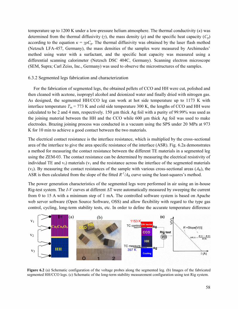
58
temperature up to 1200 K under a low-pressure helium atmosphere. The thermal conductivity (κ) was
determined from the thermal diffusivity (γ), the mass density (ρ) and the specific heat capacity (Cp)
according to the equation κ = γρCp. The thermal diffusivity was obtained by the laser flash method
(Netzsch LFA-457, Germany), the mass densities of the samples were measured by Archimedes’
method using water with a surfactant, and the specific heat capacity was measured using a
differential scanning calorimeter (Netzsch DSC 404C, Germany). Scanning electron microscope
(SEM, Supra; Carl Zeiss, Inc., Germany) was used to observe the microstructures of the samples.
6.3.2 Segmented legs fabrication and characterization
For the fabrication of segmented legs, the obtained pellets of CCO and HH were cut, polished and
then cleaned with acetone, isopropyl alcohol and deionized water and finally dried with nitrogen gas.
As designed, the segmented HH/CCO leg can work at hot side temperature up to 1173 K with
interface temperature Tm = 773 K and cold side temperature 300 K, the lengths of CCO and HH were
calculated to be 2 and 4 mm, respectively. 150 µm thick Ag foil with a purity of 99.99% was used as
the joining material between the HH and the CCO while 600 µm thick Ag foil was used to make
electrodes. Brazing joining process was conducted in a vacuum using the SPS under 20 MPa at 973
K for 10 min to achieve a good contact between the two materials.
The electrical contact resistance is the interface resistance, which is multiplied by the cross-sectional
area of the interface to give the area specific resistance of the interface (ASR). Fig. 6.2a demonstrates
a method for measuring the contact resistance between the different TE materials in a segmented leg
using the ZEM-03. The contact resistance can be determined by measuring the electrical resistivity of
individual TE and v3) materials (v1 and the resistance across the interface of the segmented materials
(v2). By measuring the contact resistances of the sample with various cross-sectional areas (AR), the
ASR is then calculated from the slope of the fitted R-1/AR curve using the least-squares’s method.
The power generation characteristics of the segmented legs were performed in air using an in-house
Rig-test system. The I-V curves at different ∆T were automatically measured by sweeping the current
from 0 to 15 A with a minimum step of 1 mA. The controlled software system is based on Apache
web server software (Open Source Software, OSS) and allow flexibility with regard to the type gas
control, cycling, long-term stability tests, etc. In order to define the accurate temperature difference
(a) v1
v2
v3
I+
HH
Ca3Co4O9
(b)
Figure 6.2 (a) Schematic configuration of the voltage probes along the segmented leg. (b) Images of the fabricated
segmented HH/CCO legs. (c) Schematic of the long-term stability measurement configuration using test Rig system.

59
across the leg, 0.5 mm n-type thermocouple was directly inserted inside the Ag electrodes at the
vicinity of the top part of the leg. The thermocouple at the hot side is also used for setting up the PID
of the heater controller (Fig. 6.2b). To minimize the heat losses during the test, the heater was
covered by a thick layer of silica felts.
6.4 Results and discussion
6.4.1 Electrical properties of single and segmented legs
In thermoelectric power generation devices, the magnitude of the measured electrical current is
inversely proportional to the total electrical resistivity of the TE leg including their interfacial
electrical contact resistance. For a segmented TE leg, the total contact resistance usually increases
due to the increasing number of interfaces. Therefore, minimizing the electrical contact resistance
between joined materials is of prime important in the module construction process.
Fig. 6.3a shows the temperature dependence of the electrical resistivity of CCO, HH, and segmented
HH/CCO legs. As expected, the HH samples revealed a metallic conduction behavior while the CCO
sample displayed a semiconductor-like electrical resistivity. As can be seen from this figure, the
electrical resistivity of CCO is higher by a factor of eight compared with the HH in the low
temperature range. Unsurprisingly, the electrical resistivity of segmented HH/CCO is between the
electrical resistivity of CCO and HH. The experimental result exhibited the same tendency with the
calculated one. The difference between these curves could be attributed to the interfacial electrical
contact resistance at joint part of HH/Ag/CCO. Fig. 6.3b displays the contact resistance of the joint
part as a function of temperature. Over measured temperature range, the contact resistance values are
around 100 µΩcm2, which is lower than the previously reported values of 800 µΩcm2 for the
electrical contacts of pure Ca3Co4O9+ with Fe22Cr electrode [125]. There is no crack or gap could be
observed at the interfaces between HH and CCO with Ag (see Fig. 6.3b inset). In addition, EDX
Figure 6.3 (a) Temperature dependence of the electrical resistivity of CCO, HH, and segmented HH/CCO. Star
symbol curve denotes the calculated electrical resistivity. (b) The electrical contact resistance of joint interface
HH/Ag/CCO as a function of temperature, inset SEM picture of HH/Ag/CCO.

60
analysis at the interfacial region (not shown here) revealed that there is no reaction or significant
diffusion layer. These observation may explain for the lower measured interfacial contact resistance
than that reported in [30] with Fe22Cr electrode. Measurement of the contact resistance of HH/Ag at
room temperature revealed that the electrical contact resistance is in the order of 5 µΩcm2,
suggesting that the contact resistance at the cold side of HH/CCO segmented leg is small. The total
electrical resistance of the TE leg is the sum of the resistances of the TE materials Rlegs without silver
electrodes and the total contact resistance RC, which includes the contact resistances at the joining
part, the hot and the cold side junctions. At hot and cold side temperatures of 1173/300 K, the ratio of
RC/Rlegs is about 0.08. These results indicate that the Ag brazing is an effective way to achieve low
electrical contact resistance.
6.4.2 Thermopower at small and large ∆T
For the thermoelectric modules
construction, it is important that the TE
properties of a single or segmented leg
can be maintained after the joining
process. Therefore in this work, the TE
properties as a function of temperature
of joined segmented legs of HH/CCO as
well as single HH and CCO were
carefully characterized. Fig. 6.4a shows
the temperature dependence of the
Seebeck coefficient () of the single
CCO, HH and the segmented HH/CCO
legs. For both the single and segmented
samples, the Seebeck coefficient ()
increased with increasing temperature
(Fig. 6.4a). The values of CCO were
measured to be about 150 V/K and 235
V/K at room temperature and 1140 K,
respectively. As for the HH alloys,
increased from 160 to 230 V/K as the
temperature increased from room
temperature to 700 K. In the segmented
HH/CCO, the values were in between
the values of two single components.
The intrinsic value of segmented leg
can be expressed via single components
as [126]:
Figure 6.4 (a) Temperature dependence of Seebeck coefficient of
CCO, HH, segmented HH/CCO legs at small temperature
gradient. (b) The calculated and experimental total Seebeck
coefficient of the segmented leg HH/CCO under large
temperature gradient.

61
𝑠𝑒𝑔 =∆𝑉
∆𝑇=
𝐻𝐻𝐻𝐻+CCOCCO
𝐻𝐻+CCO (6.7)
Where seg is the Seebeck coefficient of the segmented HH/CCO leg, HH, HH, CCO, CCO are
thermal conductivity, Seebeck coefficient of HH alloys, thermal conductivity and Seebeck coefficient
of CCO, respectively. In the calculation of seg using equation (6.7), the thermal contact of CCO and
HH with silver filler was neglected. The measured seg is in good agreement with the calculation
although there is a small fluctuation in the temperature range from 550 to 700 K (Fig. 6.4a). These
results indicated that the silver brazing at the interface preserved the intrinsic thermopower of the
segments at small temperature difference.
Fig. 6.4b shows the calculated and experimental open circuit voltage (∆Voc) of the segmented leg
HH/CCO at various temperature differences (∆T). It can be seen that the open circuit voltage
increased rapidly with increasing ∆T. The experimental and calculated ∆Voc curves are well fit,
suggesting that thermal contact resistance at the interfaces as well as the heat loss through the
segmented leg are very small. The relationship between the open-circuit voltage ∆Voc and the value
of the single TE material can be then expressed as [7]:
∆𝑉𝑜𝑐 = ∫ (𝑇)𝑑𝑇𝑇ℎ
𝑇𝑐 (6.8)
Where Th and Tc are the hot and cold side temperatures, respectively. As for the segmented leg,
equation (6.8) can be rewritten as:
∆𝑉𝑜𝑐−𝑠𝑒𝑔 = ∫ CCO(𝑇)dTTℎ
T𝑚+ ∫ 𝐻𝐻(𝑇)dT
Tm
T𝑐 (6.9)
where Tm is the temperature at the connection junction. In case of the open circuit voltage the Tm can
be determined by the conservation of the heat transfer at the junction. The one-dimensional the heat
flow equation, q, can be expressed as Fourier's law:
𝑞 = ∆𝑇
𝑙𝐴 (6.10)
Where A is the cross-sectional area and l is the length of the TE leg. Tm can then be obtained as:
𝑇𝑚 =𝐶𝐶𝑂𝑇ℎ𝑙𝐻𝐻+𝐻𝐻𝑇𝑐𝑙𝐶𝐶𝑂
𝐶𝐶𝑂𝑙𝐻𝐻+𝐻𝐻𝑙𝐶𝐶𝑂 (6.11)
Th, Tc, lHH and lCCO are the hot side temperature, the cold side temperature, the length of HH and the
length of CCO, respectively. Under the highest hot side temperature of 1153 K and cold side of 397
K, Tm is found to be 737 K, and the calculated ∆Voc-seg of the segmented leg was 160 mV that is
almost the same as the measured value of 158.6 mV. The measured data of ∆Voc-seg (blue open circle)
exhibits similar tendency with the calculated line (red solid line). This result again suggests that the
silver brazing is a suitable material for joining between semi-metal (HH) and oxide materials (CCO).
6.4.3 Power generation characteristics
Fig. 6.5a exhibits the experimental results on the voltage V and output power density Pd depended
on the current density J of the segmented HH/CCO leg at various applied temperature gradients. As
can be seen, both V and Pd present the same tendency of increasing values as the temperature
gradient increases. At the highest applied temperature difference T = 756 K (Th/T
c = 1153 K/397

62
K), the measured open circuit voltage (Voc ≡ ∆Voc-seg) of the segmented leg was found to be 158.6
mV, and the measured maximum output power density reached a value of 2.34 W/cm2 at a current
density of 30 A/cm2 and a voltage of 81 mV (Fig. 6.5a). In practice of making TEG, the contact
resistance is one of the main factors affecting the conversion efficiency [30,50]. In order to evaluate
this effect, the measured power generation characteristics of the segmented legs were analyzed and
compared with the theoretical results under both ideal (no contact resistance) and practical conditions
(including contact resistance). The magnitude of the output current density, J = I/A, is proportional to
the sum of the internal resistances of the TE leg, Rint, and the external resistive load, RLoad, and it is
given by the following expression [7]:
𝐽 =𝐼
𝐴=
𝑉𝑜𝑐
𝐴(𝑅𝑖𝑛𝑡+𝑅𝐿𝑜𝑎𝑑) (6.12)
where Rint = Rleg + RC is the sum of the resistances of the segmented legs without metal electrodes Rleg
and the total contact resistance RC.
The output power density of the leg as a function of Voc and the resistance is given by
𝑃𝑑 = 𝐽2𝑅𝐿𝑜𝑎𝑑 =𝑉𝑜𝑐
2
𝐴[
𝑅𝐿𝑜𝑎𝑑
(𝑅𝑖𝑛𝑡+𝑅𝐿𝑜𝑎𝑑)2] (6.13)
Equation (6.13) clearly shows that the power output of the leg depends on the Seebeck coefficient
(via Voc), the internal resistance and the external load resistance. The maximum output power density
(PMax) occurs when an external load resistance is equal to the internal resistance. To operate
thermoelectric devices at a maximum output power, the load resistance needs to be continuously
adjusted to match the internal resistance.
𝑃𝑀𝑎𝑥 =𝑉𝑜𝑐
2
4𝐴𝑅𝑖𝑛𝑡 (6.14)
Disregarding the varying dimensions of the segmented legs due to thermal expansion, it is obvious
that the smaller the internal resistance, the higher the maximum output power obtained. In our
measurement, the influence of heat losses (radiation and convection) could be negligible since the
segmented leg is small and well covered by a thick layer of the thermal insulator material (silica
felts). To investigate the influence of the electrical contact resistance on the conversion efficiency of
segmented leg, the model described in detail in Ref. [24] was used. Fig. 6.5b shows the experimental
Figure 6.5 (a) Voltages and output power for the segmented HH/CCO legs as a function of current density under
different temperature gradient. (b) The experiment and calculation of V(J) and the efficiency of the segmented legs
with and without the electrical contact resistances at highest temperature difference.

63
and calculated V-J and -J curves with and without the electrical contact resistances for the
segmented leg at the highest temperature difference. As seen in Fig. 6.5b, the measured voltage, V,
(blue open circle) fitted well with the calculated one (blue solid line) which included the contact
resistance, RC. From the slope of the I-V curves, the electrical resistance of the segmented leg was
determined to be 164.2 mΩ and 179.6 mΩ for the conditions with and without interfacial contact
resistances, respectively. These results indicate that the electrical contact resistance contributed about
8.6% to the total resistance of the leg, which is in good agreement with calculated 8% under ideal
one-dimensional heat flow (hot and cold side temperatures of 1173/300 K). The efficiency as a
function of current density has also been calculated for different cases, and the maximum values
were found to be 7.6% and 5% for the segmented HH/CCO leg without and with contact
resistances, respectively. The efficiency of our segmented leg is comparable to the efficiency of
commercial modules (e.g., module TG12-4-01Lby Marlow Industries, Inc.) constructed from state-
of-the-art p and n TE materials but lower than the BiTe/PbTe segmented modules, which can reach
6.5% [28]. This is the first time an oxide-based segmented leg has been tested in an oxidative
condition at high temperature. The results of the test clearly show that contact resistance strongly
influenced on the total conversion efficiency, and, in this case, the suppression was about 35%. This
investigation suggests that the efficiency of segmented leg can be significantly improved by reducing
further the contact resistance. Forming a buffer layer of good conductive material of e.g. metal or
alloy between oxide and electrode may be a good solution to minimize the contact resistance.
6.4.4 Long-term stability investigation
Besides improving the thermoelectric conversion efficiency of TEGs, the long-term stability is
equally important for application of heat-electricity energy conversion. Oxide-based TEGs can be
potentially used for waste heat recovery
at high temperatures e.g., >750 K from
metal refining furnaces, which is often
switched off once/month. Therefore, in
this study we have performed the long
term stability test of the segmented leg
at a constant high temperature. Fig. 6.6
displays the maximum power density
and the changed total resistivity over a
period of 336 h for the segmented
HH/CCO leg. All the measurements
were conducted in air by keeping the hot
and the cold side temperatures at
1153/397 K. The I-V curves during these
measurements were recorded every 30
min. The overall resistances of the legs
including silver joint and electrodes
were then calculated from the slope of Figure 6.6 The long term stability test of the HH/Ag/CCO leg
in air under hot and cold side temperatures of 1153/397 K.

64
the I-V curves. Interestingly, the total resistance and the maximum power density of the segmented
HH/CCO leg remain almost constant up to 336 hours. In addition, the I-V curves (not shown here)
were linear pointing out that the Ohmic contacts were maintained during the test at high temperature.
Fig. 6.7 shows SEM images of the HH and CCO with Ag joint cross-section at 0 h and 336 h
operated at 1153 K. It can be seen from the micrographs that interfacial contacts remained the same
good quality i.e. no evidence for cracks or elemental diffusions was observed at the interfaces. This
observation is in good agreement with the almost unchanging total resistance of the HH/CCO
segmented leg over a long period of holding time.
Fig. 6.7 shows SEM images of the HH and Ca3Co4O9 with Ag joint cross-section before and after the
long-term experiments. The micrographs confirm that contacts are stable, i.e. no evidence for cracks
or elemental diffusions were observed at the interfaces. Noticeably, microstructure of Ca3Co4O9 was
even enhanced after a long time testing at high temperature.
6.5 Conclusions
In summary, for the first time the segmented p-type leg of the half-Heusler
Ti0.3Zr0.35Hf0.35CoSb0.8Sn0.2 and the doped misfit-layered cobaltite Ca2.8Lu0.15Ag0.05Co4O9+ (CCO)
was successfully fabricated and characterized using the silver brazing joining technique. With this
Ca2.8Lu0.15Ag0.05Co4O9+
2 µm
Ag filler
0 Hrs 336 Hrs
Ti0.3Zr0.35Hf0.35CoSb0.8Sn0.2
Ca2.8Lu0.15Ag0.05Co4O9+
Ag filler
Ti0.3Zr0.35Hf0.35CoSb0.8Sn0.2
Ag filler Ag filler
2 µm
Figure 6.7 SEM joint interface of CCO/Ag and HH/Ag after joining 0 Hrs and after test 336
Hrs in air with hot and cold side temperatures of 1153/397 K.

65
technique, the total contact resistance was obtained to be about 8% of the total resistance of
segmented leg. The calculation results pointed out that CCO and HH have their compatibility factors
close to each other, and thus the efficiency of HH/CCO segmented leg could be improved to a value
of 9.1% under conditions without parasitic losses. The output power generation characteristics of the
segmented legs were measured in air with various temperature gradients, T. At T of about 756 K,
the maximum generated power density attained 2.34 W/cm2 corresponding to 5% conversion
efficiency, which is about 65% of the ideal condition. Long term stability investigation for over two
weeks in air suggests that this oxide-based segmented leg is very promising for generating electricity
from high temperature waste heat. According to our recent report [134], n-type segmented leg of
doped ZnO and half-Heusler could be a promising partner to build up low-cost high performance
oxide-based TEG.
.

66
Chapter 7 Summaries and outlooks
Summary of some selected main results obtained in this thesis are given below:
Theoretical description of segmented thermoelectric generators have been formulated and
numerically solved. A rule of thumb when selecting a segmented material is that the difference in
compatibility factors of two different thermoelectric materials should be within a factor of two. This
has been proven theoretically by obtaining the conversion efficiency of n-type segmented ZnO with
HH and CoSb. The one-dimensional numerical modelling has been developed and used to evaluate
the efficiency of single and segmented oxide based materials. A new concept was used to select
segmented materials and it is based on their figure-of-merit, the “efficiency ratio” and their
compatibility factors. In comparison with other metallic alloys, it was found that oxides materials are
good candidates for hot-side materials for building up low-cost, high performance segmented
legs/unicouples. A maximum efficiency of more than 10% was calculated for the unicouples made of
segmented legs of p-Ca3Co4O9 and n-ZnO with intermetallic compounds such as HH and BiTe. The
results of the modeling indicate that building TEG-based segmented legs include a trade-off between
the increment in conversion efficiencies and the module processing and fabrication costs, effects that
should be taken into consideration when building a module. The obtained results suggest a useful
tool to construct low-cost and high-efficiency thermoelectric modules based on oxide materials for a
high-temperature power generation.
n-type oxide CaMnO3 compound includes environmentally friendly materials and offers a
stable thermoelectric properties in oxidative condition at high temperature and used in commercial
oxide modules. The effect of Fe substitution on the structure and the high-temperature thermoelectric
properties of Ca0.9Y0.1Mn1-xFexO3 (x = 0, 0.05, 0.1, 0.15, 0.2, 0.25) was investigated in details.
Structural analysis shows that lattice parameters slightly increase with increasing amount of Fe
substituent, which originates from the difference in the ionic radii between Fe and Mn ions. The
thermoelectric properties were found to be improved for the Fe-doped samples with x < 0.1,
particularly for the SPS samples with further annealing mainly due to the increase in the Seebeck
coefficient that could overcome the simultaneous decrease of the electrical conductivity. The thermal
conductivity was suppressed by the substitution of Fe for Mn. The maximum zT attained was 0.11 at
1150 K for the sample x = 0.05, which is about 20% higher than the x = 0 sample. Further study
should be performed with finer Fe substituent tuning with x < 0.1 in order to optimize thermoelectric
as well as mechanical properties of these compounds.
For the first time, a high-temperature segmented thermoelectric based-oxide module
comprising of p-legs segmentation of Ti0.3Zr0.35Hf0.35CoSb0.8Sn0.2, and the misfit-layered cobaltite
Ca3Co4O9+, and n-legs 2% Al-doped ZnO has been successfully fabricated and tested. Numerical
modeling was used to optimize and design the TEG. The input for the model was the experimental
data on the TE properties of the legs, as well as on electrical contact resistance. The enhancement of
output power generation of the segmented TEG originated from the properties of the HH alloy in the
low-to-mid temperature range, compared with those of the oxides. The high-performance of the
segmented TEG also benefited from the reduction in the total internal resistance of the module due to

67
the low contact resistance between the HH alloy and the Ag electrodes. At a hot side temperature of
1173 K corresponding to a temperature gradient of about 700 K, the maximum power density of the
module reached 0.65 W/cm2, a value which is among the highest reported so far for oxide-based
modules. Using 3D numerical modeling in combination with the experimental data, we found that the
efficiency of the segmented TEG (1.16%) was significantly improved compared with the non-
segmented TEG (0.37%). Initial long-term testing showed that a segmented oxide module is stable
and exhibits a promising power generation e.g. from waste heat at high temperatures.
High-temperature segmented p-type leg of the half-Heusler Ti0.3Zr0.35Hf0.35CoSb0.8Sn0.2 (HH)
and the doped misfit-layered cobaltite Ca2.8Lu0.15Ag0.05Co4O9+ was successfully fabricated. The
resultant microstructure and the electrical contact resistance at the junction suggest that silver brazing
is a suitable material for joining semi-metal and oxide material. The thermoelectric properties of
single components and the segmented HH/Ca2.8Lu0.15Ag0.05Co4O9+ legs were characterized as a
function of temperature. The results also indicated that the silver brazing at the interface preserved
the intrinsic thermopower of the segments at small temperature difference. The output power
generation characteristics of the segmented legs were measured in air under various temperature
gradients. At T of about 756 K, the maximum generated power density was attained with a value of
2.34 W/cm2 corresponding to 5% conversion efficiency, which is of date the highest value reported
on oxide-based thermoelectrics. Long-term stability investigation in air suggests that this oxide-based
segmented leg is very promising for generation of electricity from high-temperature waste heat.
Outlook of the future prospects
Three-segment p-type BiTe/HH/Ca3Co4O9 would be a good solution to improve the total
conversion efficiency further.
While the thermoelectric performance of n-type oxide materials is still much lower than the
p-type counterparts, a uni-leg TEG which uses single segmented p-legs and metal connection may be
considered a good solution.
Doped CaMnO3 oxide is a promising material, i.e. stable in air, and may be a good candidate
for hot side material for a high-temperature segmentation if ZnO:Al will be replaced.

68
References
[1] Pollock DD. General Principles and Theoretical Considerations Phenomena 1995.
[2] Seebeck, T.J., Magnetische polarisation der metalle und erze durck temperatur- differenz, Abh. K.
Akad. Wiss., 265 (1823). n.d.
[3] Snyder GJ, Toberer ES. Complex thermoelectric materials. Nat Mater 2008;7:105–14.
doi:10.1038/nmat2090.
[4] Biswas K, He J, Blum ID, Wu C-I, Hogan TP, Seidman DN, et al. High-performance bulk
thermoelectrics with all-scale hierarchical architectures. Nature 2012;489:414–8.
doi:10.1038/nature11439.
[5] Zhao L-D, Lo S-H, Zhang Y, Sun H, Tan G, Uher C, et al. Ultralow thermal conductivity and high
thermoelectric figure of merit in SnSe crystals. Nature 2014;508:373–7. doi:10.1038/nature13184.
[6] Heikes RR, Ure RW. Thermoelectricity: science and engineering. Interscience Publishers; 1961.
[7] M.H. Cobble. Calculation of generator performance. In D.M. Rowe, editor, CRC Handbook of
Thermoelectrics, Chapter 39, pp. 489-501. CRC Press, Boca Raton, FL, 1995 n.d.
[8] Le Thanh Hung, Ngo Van Nong, Gerald Jeffrey Snyder, Benjamin Balke, Li Han, Rasmus Bjørk,
Pham Hoang Ngan, Tim C. Holgate, Søren Linderoth and NP. Segmented thermoelectric oxide-
based module. Energy 2014.
[9] Mele P, Kamei H, Yasumune H, Matsumoto K, Miyazaki K. Development of thermoelectric
module based on dense Ca3Co4O9 and Zn0.98Al0.02O legs. Met Mater Int 2014;20:389–97.
doi:10.1007/s12540-014-2024-7.
[10] Lim C-H, Choi S-M, Seo W-S, Park H-H. A Power-Generation Test for Oxide-Based
Thermoelectric Modules Using p-Type Ca3Co4O9 and n-Type Ca0.9Nd0.1MnO3 Legs. J Electron
Mater 2011;41:1247–55. doi:10.1007/s11664-011-1868-6.
[11] Fergus JW. Oxide materials for high temperature thermoelectric energy conversion. J Eur Ceram
Soc 2012;32:525–40. doi:10.1016/j.jeurceramsoc.2011.10.007.
[12] Souma M. ; Shigeno, M. ; Ohba, Y. ; Nakamura, N. ; Shimozaki, T. T. O. Power generation
characteristics of oxide thermoelectric modules incorporating nanostructured ZnO sintered
materials. 2007 26th Int. Conf. Thermoelectr., IEEE; 2007, p. 38–41.
doi:10.1109/ICT.2007.4569418.
[13] Matsubara I, Funahashi R, Takeuchi T, Sodeoka S, Shimizu T, Ueno K. Fabrication of an all-oxide
thermoelectric power generator. Appl Phys Lett 2001;78:3627. doi:10.1063/1.1376155.
[14] Funahashi R, Mikami M, Mihara T, Urata S, Ando N. A portable thermoelectric-power-generating
module composed of oxide devices. J Appl Phys 2006;99:66117. doi:10.1063/1.2180449.
[15] Souma T, Ohtaki M. ; Ohba, Y. ; Nakamura, N. ; Shimozaki, T. M; S. Fabrication and power
generation characteristics of p-NaCo2O4 n-ZnO oxide thermoelectric modules 2006.
doi:10.1109/ICT.2006.331386.
[16] Urata S, Funahashi R, Mihara T. Power generation of p-type Ca3Co4O9/n-type CaMnO3 module.
2006 25th Int. Conf. Thermoelectr., IEEE; 2006, p. 501–4. doi:10.1109/ICT.2006.331343.
[17] Funahashi R, Urata S. Fabrication and Application of an Oxide Thermoelectric System. Int J Appl
Ceram Technol 2007;4:297–307. doi:DOI: 10.1111/j.1744-7402.2007.02144.x.
[18] Choi S-M, Lee K-H, Lim C-H, Seo W-S. Oxide-based thermoelectric power generation module
using p-type Ca3Co4O9 and n-type (ZnO)7In2O3 legs. Energy Convers Manag 2011;52:335–9.
doi:10.1016/j.enconman.2010.07.005.
[19] Ure RW, Heikes RR. Materials requirements for segmented thermoelectric materials. Adv Energy
Convers 1962;2:177–81. doi:10.1016/0365-1789(62)90022-X.

69
[20] Vikhor LN, Anatychuk LI. Generator modules of segmented thermoelements. Energy Convers
Manag 2009;50:2366–72. doi:10.1016/j.enconman.2009.05.020.
[21] Swanson BW, Somers E V., Heikes RR. Optimization of a Sandwiched Thermoelectric Device. J
Heat Transfer 1961;83:77. doi:10.1115/1.3680473.
[22] Cohen RW, Abeles B. Efficiency Calculations of Thermoelectric Generators with Temperature
Varying Parameters. J Appl Phys 1963;34:1687. doi:10.1063/1.1702659.
[23] Sherman B, Heikes RR, Ure RW. Calculation of Efficiency of Thermoelectric Devices. J Appl
Phys 1960;31:1. doi:10.1063/1.1735380.
[24] G. J. Snyder, Thermoelectric Power Generation: Efficiency and Compatibility (CRC Press, Taylor
& Francis Group, Boca Raton, FL, USA, 2006), Chap. 9, n.d.
[25] Snyder GJ. Application of the compatibility factor to the design of segmented and cascaded
thermoelectric generators. Appl Phys Lett 2004;84:2436. doi:10.1063/1.1689396.
[26] Snyder G, Ursell T. Thermoelectric Efficiency and Compatibility. Phys Rev Lett 2003;91.
doi:10.1103/PhysRevLett.91.148301.
[27] Fleurial J-P, Bux S, Caillat T. Engineering of Novel Thermoelectric Materials and Devices for
Next Generation, Long Life, 20% Efficient Space Power Systems. 11th Int. Energy Convers. Eng.
Conf., Reston, Virginia: American Institute of Aeronautics and Astronautics; 2013.
doi:10.2514/6.2013-3927.
[28] D’Angelo J, Case ED, Matchanov N, Wu C-I, Hogan TP, Barnard J, et al. Electrical, Thermal, and
Mechanical Characterization of Novel Segmented-Leg Thermoelectric Modules. J Electron Mater
2011;40:2051–62. doi:10.1007/s11664-011-1717-7.
[29] Crane DT, Kossakovski D, Bell LE. Modeling the Building Blocks of a 10% Efficient Segmented
Thermoelectric Power Generator. J Electron Mater 2009;38:1382–6. doi:10.1007/s11664-009-
0673-y.
[30] El-Genk MS, Saber HH. High efficiency segmented thermoelectric unicouple for operation
between 973 and 300 K. Energy Convers Manag 2003;44:1069–88. doi:10.1016/S0196-
8904(02)00109-7.
[31] Wojciechowski KT, Zybala R, Leszczynski J, Nieroda P, Schmidt M, Gajerski R, et al.
Performance characterization of high-efficiency segmented Bi2Te3/CoSb3 unicouples for
thermoelectric generators 2012:467–70. doi:10.1063/1.4731597.
[32] Anatychuk LI, Vikhor LN, Strutynska LT, Termena IS. Segmented Generator Modules Using
Bi2Te3-Based Materials. J Electron Mater 2011;40:957–61. doi:10.1007/s11664-010-1468-x.
[33] El-Genk MS, Saber HH, Caillat T, Sakamoto J. Tests results and performance comparisons of
coated and un-coated skutterudite based segmented unicouples. Energy Convers Manag
2006;47:174–200. doi:10.1016/j.enconman.2005.03.023.
[34] El-Genk MS, Saber HH. High efficiency segmented thermoelectric unicouple for operation
between 973 and 300 K. Energy Convers Manag 2003;44:1069–88. doi:10.1016/S0196-
8904(02)00109-7.
[35] Caillat T, Fleurial J-P, Snyder GJ, Borshchevsky A. Development of high efficiency segmented
thermoelectric unicouples. Proc. ICT2001. 20 Int. Conf. Thermoelectr. (Cat. No.01TH8589),
IEEE; n.d., p. 282–5. doi:10.1109/ICT.2001.979888.
[36] Yatir Sadia, Ohad Ben-Yehuda YG. Highly Efficient Segmented p-type Thermoelectric Leg.
Dordrecht: Springer Netherlands; 2013. doi:10.1007/978-94-007-4984-9_5.
[37] El-Genk MS, Saber HH, Caillat T. Efficient segmented thermoelectric unicouples for space power
applications. Energy Convers Manag 2003;44:1755–72. doi:10.1016/S0196-8904(02)00217-0.

70
[38] Sadia Y, Gelbstein Y. Silicon-Rich Higher Manganese Silicides for Thermoelectric Applications. J
Electron Mater 2012;41:1504–8. doi:10.1007/s11664-012-1936-6.
[39] El-Genk MS. Performance Tests of Skutterudites and Segmented Thermoelectric Converters. AIP
Conf. Proc., vol. 699, AIP; 2004, p. 541–52. doi:10.1063/1.1649615.
[40] Ben-Yehuda O, Gelbstein Y, Dashevsky Z, George Y, Dariel MP. Functionally Graded Bi2Te3
based material for above ambient temperature application. 2007 26th Int. Conf. Thermoelectr.,
IEEE; 2007, p. 82–5. doi:10.1109/ICT.2007.4569429.
[41] Orrù R, Licheri R, Locci AM, Cincotti A, Cao G. Consolidation/synthesis of materials by electric
current activated/assisted sintering. Mater Sci Eng R Reports 2009;63:127–287.
doi:10.1016/j.mser.2008.09.003.
[42] Matsugi K, Wang Y, Hatayama T, Yanagisawa O, Syakagohri K. Application of electric discharge
process in joining aluminum and stainless steel sheets. J Mater Process Technol 2003;135:75–82.
doi:10.1016/S0924-0136(02)01040-3.
[43] Matsugi K, Konishi M, Yanagisawa O, Komatsu M. Design and manufacture of an impact–electric
current discharge joining machine. Mater Sci Eng A 2003;350:195–201. doi:10.1016/S0921-
5093(02)00727-X.
[44] Van Nong N, Pryds N, Linderoth S, Ohtaki M. Enhancement of the thermoelectric performance of
p-type layered oxide Ca₃Co₄O(₉+δ) through heavy doping and metallic nanoinclusions. Adv
Mater 2011;23:2484–90. doi:10.1002/adma.201004782.
[45] Hung LT, Nong N Van, Han L, Minh D Le, Borup KA, Iversen BB, et al. High-temperature
thermoelectric properties of Ca0.9Y0.1Mn1−x Fe x O3 (0 ≤ x ≤ 0.25). J Mater Sci 2012;48:2817–
22. doi:10.1007/s10853-012-6834-z.
[46] Han L, Hung LT, Nong N, Pryds N, Linderoth S. The Influence of Spark Plasma Sintering
Temperature on the Microstructure and Thermoelectric Properties of Al,Ga Dual-Doped ZnO. J
Electron Mater 2012;42:1573–81. doi:10.1007/s11664-012-2325-x.
[47] Grange P, Delmon B, editors. Interfaces in New Materials. Dordrecht: Springer Netherlands; 1991.
doi:10.1007/978-94-011-3680-8.
[48] Singh M, Ohji T, Asthana R, Mathur S, editors. Ceramic Integration and Joining Technologies.
Hoboken, NJ, USA: John Wiley & Sons, Inc.; 2011. doi:10.1002/9781118056776.
[49] http://tellurex.com/shop-products/#TPG n.d.
[50] Rowe DM. CRC Handbook of Thermoelectrics. Boca Raton, FL: CRC Press; 1995.
[51] Vining CB. An inconvenient truth about thermoelectrics. Nat Mater 2009;8:83–5.
doi:10.1038/nmat2361.
[52] Kristiansen NR, Snyder GJ, Nielsen HK, Rosendahl L. Waste Heat Recovery from a Marine
Waste Incinerator Using a Thermoelectric Generator. J Electron Mater 2012;41:1024–9.
doi:10.1007/s11664-012-2009-6.
[53] Koumoto K, Wang Y, Zhang R, Kosuga A, Funahashi R. Oxide Thermoelectric Materials: A
Nanostructuring Approach. Annu Rev Mater Res 2010;40:363–94. doi:10.1146/annurev-matsci-
070909-104521.
[54] Walia S, Balendhran S, Nili H, Zhuiykov S, Rosengarten G, Wang QH, et al. Transition metal
oxides – Thermoelectric properties. Prog Mater Sci 2013;58:1443–89.
doi:10.1016/j.pmatsci.2013.06.003.
[55] He J, Liu Y, Funahashi R. Oxide thermoelectrics: The challenges, progress, and outlook. J Mater
Res 2011;26:1762–72. doi:10.1557/jmr.2011.108.

71
[56] Yadav GG, Susoreny J a, Zhang G, Yang H, Wu Y. Nanostructure-based thermoelectric
conversion: an insight into the feasibility and sustainability for large-scale deployment. Nanoscale
2011;3:3555–62. doi:10.1039/c1nr10555h.
[57] Koumoto K, Funahashi R, Guilmeau E, Miyazaki Y, Weidenkaff A, Wang Y, et al.
Thermoelectric Ceramics for Energy Harvesting. J Am Ceram Soc 2013;96:1–23.
doi:10.1111/jace.12076.
[58] Jood P, Mehta RJ, Zhang Y, Borca-Tasciuc T, Dou SX, Singh DJ, et al. Heavy element doping for
enhancing thermoelectric properties of nanostructured zinc oxide. RSC Adv 2014;4:6363.
doi:10.1039/c3ra46813e.
[59] Guilmeau E, Maignan A, Martin C. Thermoelectric Oxides: Effect of Doping in Delafossites and
Zinc Oxide. J Electron Mater 2009;38:1104–8. doi:10.1007/s11664-009-0815-2.
[60] Van NN, Pryds N. Nanostructured oxide materials and modules for high-temperature power
generation from waste heat. Adv Nat Sci Nanosci Nanotechnol 2013;4:023002. doi:10.1088/2043-
6262/4/2/023002.
[61] Han L, Van Nong N, Zhang W, Hung LT, Holgate T, Tashiro K, et al. Effects of morphology on
the thermoelectric properties of Al-doped ZnO. RSC Adv 2014;4:12353. doi:10.1039/c3ra47617k.
[62] Brockway L, Vasiraju VRK, Sunkara MK, Vaddiraju S. Engineering Efficient Thermoelectrics
from Large-scale Assemblies of doped ZnO Nanowires: Nanoscale Effects and Resonant-Level
Scattering. ACS Appl Mater Interfaces 2014:140811154730003. doi:10.1021/am5023489.
[63] Mikami M, Guilmeau E, Funahashi R. Enhancement of electrical properties of the thermoelectric
compound Ca 3 Co 4 O 9 through use of large-grained powder 2005:2491–7.
[64] Pichanusakorn P, Bandaru P. Nanostructured thermoelectrics. Mater Sci Eng R Reports
2010;67:19–63. doi:10.1016/j.mser.2009.10.001.
[65] Ohtaki M, Araki K, Yamamoto K. High Thermoelectric Performance of Dually Doped ZnO
Ceramics. J Electron Mater 2009;38:1234–8. doi:10.1007/s11664-009-0816-1.
[66] Bérardan D, Byl C, Dragoe N. Influence of the Preparation Conditions on the Thermoelectric
Properties of Al-Doped ZnO. J Am Ceram Soc 2010;93:2352–8. doi:10.1111/j.1551-
2916.2010.03751.x.
[67] Nong NV, Liu C-J, Ohtaki M. Improvement on the high temperature thermoelectric performance
of Ga-doped misfit-layered Ca3Co4−xGaxO9+δ (x=0, 0.05, 0.1, and 0.2). J Alloys Compd
2010;491:53–6. doi:10.1016/j.jallcom.2009.11.009.
[68] Xia C, Sugiyama J, Itahara H, Tani T. Platelet crystals of thermoelectric layered cobaltites; pure
and Sr-doped. J Cryst Growth 2005;276:519–24. doi:10.1016/j.jcrysgro.2004.11.415.
[69] Funahashi R. Waste Heat Recovery Using Thermoelectric Oxide Materials. Sci Adv Mater
2011;3:682–6. doi:10.1166/sam.2011.1200.
[70] Ngan PH, Christensen DV, Snyder GJ, Hung LT, Linderoth S, Nong N Van, et al. Towards high
efficiency segmented thermoelectric unicouples. Phys Status Solidi 2014;211:9–17.
doi:10.1002/pssa.201330155.
[71] Ma Y, Hao Q, Poudel B, Lan Y, Yu B, Wang D, et al. Enhanced thermoelectric figure-of-merit in
p-type nanostructured bismuth antimony tellurium alloys made from elemental chunks. Nano Lett
2008;8:2580–4. doi:10.1021/nl8009928.
[72] Chan TE, Venkatasubramanian R, LeBeau JM, Thomas P, Stuart J, Koch CC. Enhanced
Thermoelectric Figure-of-merit at Room Temperature in Bulk Bi(Sb)Te(Se) With Grain Size of
∼100nm. MRS Proc 2013;1543:93–8. doi:10.1557/opl.2013.948.
[73] Li D, Li R, Qin X-Y, Song C-J, Xin H-X, Wang L, et al. Co-precipitation synthesis of
nanostructured Cu3SbSe4 and its Sn-doped sample with high thermoelectric performance. Dalton
Trans 2014;43:1888–96. doi:10.1039/c3dt52447g.

72
[74] Wang S, Tan X, Tan G, She X, Liu W, Li H, et al. The realization of a high thermoelectric figure
of merit in Ge-substituted β-Zn4Sb3 through band structure modification. J Mater Chem
2012;22:13977. doi:10.1039/c2jm30906h.
[75] Yan X, Liu W, Wang H, Chen S, Shiomi J, Esfarjani K, et al. Stronger phonon scattering by larger
differences in atomic mass and size in p-type half-Heuslers Hf1−xTixCoSb0.8Sn0.2. Energy
Environ Sci 2012;5:7543. doi:10.1039/c2ee21554c.
[76] Sui J, Li J, He J, Pei Y-L, Berardan D, Wu H, et al. Texturation boosts the thermoelectric
performance of BiCuSeO oxyselenides. Energy Environ Sci 2013;6:2916.
doi:10.1039/c3ee41859f.
[77] Shi X, Yang J, Salvador JR, Chi M, Cho JY, Wang H, et al. Multiple-filled skutterudites: high
thermoelectric figure of merit through separately optimizing electrical and thermal transports. J
Am Chem Soc 2011;133:7837–46. doi:10.1021/ja111199y.
[78] Liu W, Tang X, Sharp J. Low-temperature solid state reaction synthesis and thermoelectric
properties of high-performance and low-cost Sb-doped Mg 2 Si 0.6 Sn 0.4. J Phys D Appl Phys
2010;43:085406. doi:10.1088/0022-3727/43/8/085406.
[79] Joshi G, Lee H, Lan Y, Wang X, Zhu G, Wang D, et al. Enhanced thermoelectric figure-of-merit
in nanostructured p-type silicon germanium bulk alloys. Nano Lett 2008;8:4670–4.
doi:10.1021/nl8026795.
[80] Wang XW, Lee H, Lan YC, Zhu GH, Joshi G, Wang DZ, et al. Enhanced thermoelectric figure of
merit in nanostructured n-type silicon germanium bulk alloy. Appl Phys Lett 2008;93:193121.
doi:10.1063/1.3027060.
[81] Brown SR, Kauzlarich SM, Gascoin F, Snyder GJ. Yb 14 MnSb 11 : New High Efficiency
Thermoelectric Material for Power Generation. Chem Mater 2006;18:1873–7.
doi:10.1021/cm060261t.
[82] May AF, Flage-Larsen E, Snyder GJ. Electron and phonon scattering in the high-temperature
thermoelectric La_3Te_4−zM_z (M=Sb,Bi). Phys Rev B 2010;81:125205.
doi:10.1103/PhysRevB.81.125205.
[83] J. Yang, T. Caillat, MRS Bull. 2006, 31 224–229. Thermoelectric Materials for Space and
Automotive Power Generation n.d.
[84] Kambe M, Jinushi T, Ishijima Z. Encapsulated Thermoelectric Modules and Compliant Pads for
Advanced Thermoelectric Systems. J Electron Mater 2010;39:1418–21. doi:10.1007/s11664-010-
1315-0.
[85] Nong N V., Ohtaki M. Thermoelectric properties and local electronic structure of rare earth-doped
Ca3Co2O6. 2006 25th Int. Conf. Thermoelectr., IEEE; 2006, p. 62–5.
doi:10.1109/ICT.2006.331270.
[86] Ito M, Furumoto D. Microstructure and thermoelectric properties of NaxCo2O4/Ag composite
synthesized by the polymerized complex method. J Alloys Compd 2008;450:517–20.
doi:10.1016/j.jallcom.2006.12.081.
[87] Kikuchi a., Okinaka N, Akiyama T. A large thermoelectric figure of merit of La-doped SrTiO3
prepared by combustion synthesis with post-spark plasma sintering. Scr Mater 2010;63:407–10.
doi:10.1016/j.scriptamat.2010.04.041.
[88] Bocher L, Aguirre MH, Logvinovich D, Shkabko A, Robert R, Trottmann M, et al. CaMn(1-
x)Nb(x)O3 (x < or = 0.08) perovskite-type phases as promising new high-temperature n-type
thermoelectric materials. Inorg Chem 2008;47:8077–85. doi:10.1021/ic800463s.
[89] http://www.alfa.com. Accessed 24 Novemb 2014 n.d.

73
[90] LeBlanc S, Yee SK, Scullin ML, Dames C, Goodson KE. Material and manufacturing cost
considerations for thermoelectrics. Renew Sustain Energy Rev 2014;32:313–27.
doi:10.1016/j.rser.2013.12.030.
[91] Snyder GJ. Thermoelectrics And Its Energy Harvesting: Materials, Preparation, And
Characterization In Thermoelectrics 2012.
[92] Seifert W, Pluschke V, Goupil C, Zabrocki K, Müller E, Snyder GJ. Maximum performance in
self-compatible thermoelectric elements. J Mater Res 2011;26:1933–9. doi:10.1557/jmr.2011.139.
[93] Muto A, Yang J, Poudel B, Ren Z, Chen G. Skutterudite Unicouple Characterization for Energy
Harvesting Applications. Adv Energy Mater 2013;3:245–51. doi:10.1002/aenm.201200503.
[94] Garcia-Canadas J, Min G. Preparation and characterisation of contacts for high temperature
thermoelectric modules 2012:454–7. doi:10.1063/1.4731594.
[95] Wojciechowski KT, Zybala R, Mania R. High temperature CoSb3–Cu junctions. Microelectron
Reliab 2011;51:1198–202. doi:10.1016/j.microrel.2011.03.033.
[96] Le Thanh Hung, Ngo Van Nong, G. Jeffrey Snyder, Li Han, Eugen Stamate, Man Hoang Viet,
Benjamin Balke, Søren Linderoth and NP. High Performance p-type Segmentation of Oxide and
Half-Heusler Alloy. Energy Convers Manag n.d.
[97] Yee SK, LeBlanc S, Goodson KE, Dames C. $ per W metrics for thermoelectric power generation:
beyond ZT. Energy Environ Sci 2013;6:2561. doi:10.1039/c3ee41504j.
[98] Han L, Nong N Van, Hung LT, Holgate T, Pryds N, Ohtaki M, et al. The influence of α- and γ-
Al2O3 phases on the thermoelectric properties of Al-doped ZnO. J Alloys Compd 2013;555:291–
6. doi:10.1016/j.jallcom.2012.12.091.
[99] Rowe DM. Thermoelectrics Handbook: Macro to Nano. CRC Press, 6000 Broken Sound Parkway
NW, Suite 300, Boca Raton, FL, 33487, 912 pages, Taylor and Francis Group.; 2006.
[100] Kosuga A, Urata S, Kurosaki K, Yamanaka S, Funahashi R. Mechanical Properties of Ca 0.9 Yb
0.1 MnO 3 /Ag Composites for n-Type Legs of Thermoelectric Oxide Devices. Jpn J Appl Phys
2008;47:6399–403. doi:10.1143/JJAP.47.6399.
[101] Wang Y, Sui Y, Fan H, Wang X, Su Y, Su W, et al. High Temperature Thermoelectric Response
of Electron-Doped CaMnO 3. Chem Mater 2009;21:4653–60. doi:10.1021/cm901766y.
[102] Flahaut D, Mihara T, Funahashi R, Nabeshima N, Lee K, Ohta H, et al. Thermoelectrical
properties of A-site substituted Ca[sub 1−x]Re[sub x]MnO[sub 3] system. J Appl Phys
2006;100:084911. doi:10.1063/1.2362922.
[103] Wang Y, Sui Y, Su W. High temperature thermoelectric characteristics of Ca[sub 0.9]R[sub
0.1]MnO[sub 3] (R=La,Pr,[ellipsis (horizontal)],Yb). J Appl Phys 2008;104:093703.
doi:10.1063/1.3003065.
[104] Bocher L, Aguirre MH, Robert R, Logvinovich D, Bakardjieva S, Hejtmanek J, et al. High-
temperature stability, structure and thermoelectric properties of CaMn1-xNbxO3CaMn1-xNbxO3
phases. Acta Mater 2009;57:5667–80. doi:10.1016/j.actamat.2009.07.062.
[105] Kosuga A, Isse Y, Wang Y, Koumoto K, Funahashi R. High-temperature thermoelectric properties
of Ca[sub 0.9−x]Sr[sub x]Yb[sub 0.1]MnO[sub 3−δ] (0≤x≤0.2). J Appl Phys 2009;105:093717.
doi:10.1063/1.3125450.
[106] Thuy NT, Minh DL, Nong NV, Bahl CRH and Pryds N 7-9, November, Ho Chi Minh city,
Vietnam (2011). No Title. Proc Press Solid State Phys Mater Sci Symp (in Press n.d.
[107] Wang HC, Wang CL, Su W Bin, Liu J, Sun Y, Peng H, et al. Doping Effect of La and Dy on the
Thermoelectric Properties of SrTiO3. J Am Ceram Soc 2011;94:838–42. doi:10.1111/j.1551-
2916.2010.04185.x.

74
[108] Poeppelmeier KR, Leonowicz ME, Scanlon JC, Longo JM, Yelon WB. Structure determination of
CaMnO3 and CaMnO2.5 by X-ray and neutron methods. J Solid State Chem 1982;45:71–9.
doi:10.1016/0022-4596(82)90292-4.
[109] Kostogloudis G. Electronic conductivity in the Pr1−xSrxCo1−yMnyO3−δ system. Solid State
Ionics 1999;118:241–9. doi:10.1016/S0167-2738(98)00193-3.
[110] Shannon RD. Revised effective ionic radii and systematic studies of interatomic distances in
halides and chalcogenides. Acta Crystallogr Sect A 1976;32:751–67.
doi:10.1107/S0567739476001551.
[111] Karim D, Aldred A. Localized level hopping transport in La(Sr)CrO_3. Phys Rev B
1979;20:2255–63. doi:10.1103/PhysRevB.20.2255.
[112] Vecherskii SI, Konopel MA, Esina NO, Batalov NN. ( 0 < x ≤ 0 . 15 ) Mixtures 2002;38:1270–6.
[113] G. H. Jonker, Philips Res. Rep., 1968, 23 131–138. No Title n.d.
[114] Ohtaki M, Tsubota T, Eguchi K, Arai H. High-temperature thermoelectric properties of
(Zn1−xAlx)O. J Appl Phys 1996;79:1816. doi:10.1063/1.360976.
[115] Wu N, Holgate TC, Nong N, Pryds N, Linderoth S. Effects of Synthesis and Spark Plasma
Sintering Conditions on the Thermoelectric Properties of Ca3Co4O9+δ. J Electron Mater
2013;42:2134–42. doi:10.1007/s11664-013-2546-7.
[116] Poon SJ, Wu D, Zhu S, Xie W, Tritt TM, Thomas P, et al. Half-Heusler phases and
nanocomposites as emerging high-ZT thermoelectric materials. J Mater Res 2011;26:2795–802.
doi:10.1557/jmr.2011.329.
[117] Snyder, G. J. “Thermoelectric Power Generation: Efficiency and Compatibility” Chapter 9, in
Thermoelectrics Handbook: Macro to Nano edited by D. M. Rowe, CRC Press (2006) n.d.
[118] Bjørk R, Christensen DV, Eriksen D, Pryds N. Analysis of the internal heat losses in a
thermoelectric generator. Int J Therm Sci 2014;85:12–20. doi:10.1016/j.ijthermalsci.2014.06.003.
[119] Jeffrey Snyder G, Caillat T. Using the Compatibility Factor to Design High Efficiency Segmented
Thermoelectric Generators. MRS Proc 2003;793:S2.1. doi:10.1557/PROC-793-S2.1.
[120] Baranowski LL, Jeffrey Snyder G, Toberer ES. Effective thermal conductivity in thermoelectric
materials. J Appl Phys 2013;113:204904. doi:10.1063/1.4807314.
[121] Chen W-H, Liao C-Y, Hung C-I, Huang W-L. Experimental study on thermoelectric modules for
power generation at various operating conditions. Energy 2012;45:874–81.
doi:10.1016/j.energy.2012.06.076.
[122] Casper F, Graf T, Chadov S, Balke B, Felser C. Half-Heusler compounds: novel materials for
energy and spintronic applications. Semicond Sci Technol 2012;27:63001. doi:10.1088/0268-
1242/27/6/063001.
[123] Liang G, Zhou J, Huang X. Analytical model of parallel thermoelectric generator. Appl Energy
2011;88:5193–9. doi:10.1016/j.apenergy.2011.07.041.
[124] Goldsmid HJ. Introduction to Thermoelectricity. vol. 121. Berlin, Heidelberg: Springer Berlin
Heidelberg; 2010. doi:10.1007/978-3-642-00716-3.
[125] Holgate TC, Han L, Wu N, Bøjesen ED, Christensen M, Iversen BB, et al. Characterization of the
interface between an Fe–Cr alloy and the p-type thermoelectric oxide Ca3Co4O9. J Alloys Compd
2014;582:827–33. doi:10.1016/j.jallcom.2013.08.096.
[126] Apertet Y, Ouerdane H, Goupil C, Lecoeur P. Series thermoelectrics. Eprint arXiv:12065649
2012:7.
[127] Park K, Lee GW. Fabrication and thermoelectric power of π-shaped Ca3Co4O9/CaMnO3 modules
for renewable energy conversion. Energy 2013;60:87–93. doi:10.1016/j.energy.2013.07.025.

75
[128] Salvador JR, Cho JY, Ye Z, Moczygemba JE, Thompson AJ, Sharp JW, et al. Thermal to
Electrical Energy Conversion of Skutterudite-Based Thermoelectric Modules. J Electron Mater
2012;42:1389–99. doi:10.1007/s11664-012-2261-9.
[129] Muto A, Kraemer D, Hao Q, Ren ZF, Chen G. Thermoelectric properties and efficiency
measurements under large temperature differences. Rev Sci Instrum 2009;80:93901.
doi:10.1063/1.3212668.
[130] Kim S. Analysis and modeling of effective temperature differences and electrical parameters of
thermoelectric generators. Appl Energy 2013;102:1458–63. doi:10.1016/j.apenergy.2012.09.006.
[131] Ohta M, Biswas K, Lo S-H, He J, Chung DY, Dravid VP, et al. Enhancement of Thermoelectric
Figure of Merit by the Insertion of MgTe Nanostructures in p-type PbTe Doped with Na2Te. Adv
Energy Mater 2012;2:1117–23. doi:10.1002/aenm.201100756.
[132] Brown SR, Kauzlarich SM, Gascoin F, Snyder GJ. Yb14MnSb11: New High Efficiency
Thermoelectric Material for Power Generation. ChemInform 2006;37.
doi:10.1002/chin.200625011.
[133] Date A, Date A, Dixon C, Akbarzadeh A. Progress of thermoelectric power generation systems:
Prospect for small to medium scale power generation. Renew Sustain Energy Rev 2014;33:371–
81. doi:10.1016/j.rser.2014.01.081.
[134] Le TH, Ngo VN, Pryds N. Physica Status Solidi A : Applications and Materials Science
Segmentation of low-cost , high efficiency oxide-based thermoelectric materials n.d.
doi:10.1002/pssa.201431626.
[135] http://sps.fdc.co.jp/whats/whats4.html n.d.