s.e.g.s. solar efficient gaming system senior design 2
TRANSCRIPT

S.E.G.S. Solar Efficient Gaming System
Senior Design 2 Final Report
Group 12
Produced by
Diijon Gumbs James Lillie
Kaniel Martin
Spring 2011

i
Table of Contents 1.0 Introduction 1
1.1 Executive Summary 1
1.2 Motivation 2
1.3 Goals 2
1.4 Budget Estimate 3
1.5 Roles and Responsibilities 4
1.6 Specifications 7
1.7 Milestones 8 1.7.1 September 1.7.2 October 1.7.3 November 1.7.4 December
1.8 Previous Works 9 1.8.1 Panel Frame Usage 1.8.2 Zomeworks Solar Tracking Systems 1.8.3 Sunarx Solar Tracking Systems 1.8.4 Patriot Solar Group’s Portable Solar Terminal 1.8.5 UCF FEC Research 1.8.6 Calbox 360 1.8.7 Portable Solar Tracker 2.0 Background/Research 13
2.1 Display 13
2.2 Solar Sensor 16 2.2.1 Cadmium Sulfide
2.2.2 Indium Antimonide 2.2.3 Silicon
2.3 Solar Panels 21 2.3.1 Solar Panel Payback Period
2.4 Voltage Regulator 27

ii
2.5 Batteries (Load) 29 2.5.1 Lead Acid Battery 2.5.2 Nickel Cadmium Battery 2.5.3 Rechargeable Alkaline Battery 2.5.4 Lithium-ion Battery 2.5.5 Nickel-Metal Hydride Battery 2.5.6 Lithium-ion Polymer Battery 2.6 Integration 34 2.7 Frame Materials 36 2.7.1 Finalized Frame Material Selection 2.8 Reflector Materials 39 2.9 Heat Sink 40 2.10 Worm Gears 40 2.11 Motor Controller 40 2.11.1 LMD18200 Motor Driver 2.11.2 Stepper Motors 2.11.3 DC Motor Brushed 2.11.4 DC Motor Brushless 2.11.5 Servo Motors 2.11.6 Motor Batteries 2.11.7 Linear Actuator 2.12 Microcontroller and I/O Board 44 2.13 Panel Sensor 50 2.14 Programmable Logic Controller 54 2.14.1 PLC Coding Languages 2.14.2 Arduino Coding Language 2.15 FPGA Information 59 3.0 Testing 61 3.1 Equipment Testing 61 3.2 Power Testing 65 3.3 Error Testing 66

iii
3.4 Durability Testing 67 3.5 Frame Testing 67 3.6 Moto Driver/Controller Testing 68 3.7 Stepper Motor Testing 69 3.8 Servo Pin Pulling Testing 70 3.9 Actuation Test Results 71
3.10 Owner’s Manual 73 3.9.1 Safety Procedure 4.0 Design 75 4.1 Schematic Design 75 4.2 Reflector Design 75 4.3 Stepper Motor Design 75 4.3.1 DC Motor Schematic 4.4 Panel Locking Mechanism Design 77 4.5 Photoresistor Design 78 4.5.1 Photoresistor Design 1 4.5.2 Photoresistor Design 2 4.5.3 Photoresistor Design 3 4.6 Order of Design Operating Functions 80 4.7 Finalized Design 81 5.0 Vendors and Budget 84 5.1 Price Listing 85 6.0 Summary and Conclusion 87 6.1 Project Summary 87 6.2 Project Conclusion 89 Appendix A: Bibliography 92

iv
Appendix B: Permission 93 Table of Tables
Table Number Name Page 1 Budget Estimate for Progress Energy funding 3 2 Specifications 8 3 Frame Materials Comparisons 37 4 Frame Materials Pricing 38 5 Reflective Materials Comparisons 39 6 Motor Actuation Comparisons 43 7 Code Comparisons 58 8 Motor Controller Pricing 84 9 Motor Pricing 85 10 Predicted Component Pricing and Suppliers 86 Table of Figures Figure Number Name Page 1 Block diagram 5 2 HD44780 Pin Layout 16 3 Spectral responsivity of a Photodiode 17 4 Power to Load Resistance Ratio 23 5 Power to Load Resistance Ratio Parallel Graph 23 6 Power to Load Resistance Ratio Series Graph 24 7 Design Payback Graph 26 8 List of Most Common Rechargeable Batteries 29 9 Battery Discharge Cycle 33 10 Regulator Schematic 35 11 Arduino Mega 2560 Image 50 12 LCD Connection in 4Bit Mode 63 13 LCD Display, Photoresistors, & Microcontroller
Schematic 64
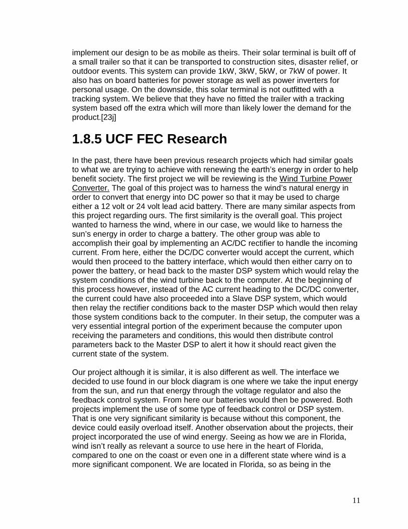
14 2.2 Ohm Power Testing 71 15 41 Ohm Power Testing 72

v
16 75 Ohm Power Testing 73 17 Stepper Motor Schematic 76 18 DC Motor Schematic 77 19 Photoresistor Implementation Design 1 79 20 Photresistor Implementation Design 3 80 21 Finalized Schematic Design 82 22 Full Scale Design Side View 83 23 Full Scale Design Top View 83 24 Final S.E.G.S. Design 91

1
1.0 Introduction
1.1 Executive Summary The project that we will be designing will be a smaller version of a solar powered tracking device equipped with features that allow the regulation of voltage and power through the usage of a voltage regulator, sunlight sensor, solar panels, as well as an actuator. Mainly, the reason why we are focusing on a solar powered tracking device is because of the emergence of solar power in the world as of today. Mainly, we have seen that solar power is becoming dominant not only with households and vehicles but with charging devices as well as smaller components like batteries. The uses of solar power are also endless which is another reason why we have decided to invest our time into building this solar powered tracking device because it incorporates features of linear controls, power electronics, and computer software into one. This device will be used to charge devices like batteries as well as other electrical devices. The main objective of this project is to design a mobile device that will be able to track sunlight and use it for conversion to energy for powering other devices. Our motivation for making this solar powered tracking device is the fact that you cannot always depend on having power supplied to you at all times, in this we have decided that the use of an alternative source of power is needed to help out during those times of need thus the reason we have decided on building this. Our technical objective is to try and build a device that is not too bulky but will be able to maintain a good amount of energy to convert to normal power (conversion from AC to DC or vice versa). It also needs to be cost-efficient so that other people in the future will be able to purchase the device for their own need as well. Our technical goal of this project is to be able to make the device withstand different types of weather conditions due to the fact that the battery will become damaged if there is too much of an overcharge to the system. If this happens then the whole solar powered device will be destroyed as a result and we need to prove that we can stabilize the system as a whole so that the device remains in tact. However, we also need to try and gather as much sunlight as possible to be able to have enough charge to power things which is why we will probably use a reflecting device such as a mirror beneath the solar panels such that we will be able to capture as much sunlight as possible. Another objective towards this project is to be able to actuate the device so that it will be able to follow the sunlight as it rises from the east and sets in the west. In doing this, the solar powered tracking device will be able to experience the full effects of the sun during the entire day excluding the fact of rain or other weather conditions that may hinder exposure to the sun during the day. The main contributor for our project will be Progress Energy as we will be registered for the 3rd Annual Senior Design Symposium on April, 8 2011. Progress Energy has helped out in the past for Senior Design students to be able

2
to receive funding for projects that deal with alternative sources including solar power. They are a well noticed company that has been around for years due to their diversity in different forms of power and engineering. Through the usage of the funding of Progress Energy as well as ourselves, we hope to be able to produce a monumental design for our presentation in Senior Design.
1.2 Motivation There are many factors motivating us to do this solar panel farm project. Coming from an ethical point of view, we are trying to save the world’s resources by relying on natural renewable energy instead of fossil fuels. In this day and age, in the green state of mind, as much is being done as possible to create electric cars, more efficient devices, and more all in hopes of conserving the resources available to us. UCF even has this similar mindset, they have started what is known as the Climate Action Plan. This plan is one in which the school is striving to use solar power and just find ways to conserve energy. Sun, is something we really have 24/7 in Florida, so building something to really harness this resource works perfectly for us. As future engineers, it is important for us to use the knowledge we have in order to give back to the community in a positive way. By using solar energy to fully substitute or even just aid in part of the electricity we use today, we are doing just that by cutting costs by lowering power bills, while keeping the environment in mind. The environment is something that not only has been abused and mistreated in the past by people. It is also something that has virtually limitless potential in terms of new resources and new ways to safely harness the earth’s power in order to make our lives easier. Take gas for example, in the past we used to use pure gasoline, then a few years back when the scare of running out of gas was in effect, more additives, or ethanol have been added to our gas system now in order to preserve its longevity. This really sparked some to consider energy efficient vehicles and to also pursue earth’s natural energies more light the sun and the wind in order to power vehicles and just aid in everyday life. In terms of personal motivations, we have all been studying engineering for some years. This solar panel farm project is going to rely on skills we have either learned in our classes, or have a genuine interest in. We are finally able to apply some of the skills we’ve learned and see how they can be efficiently incorporated into a real world situation. Some of the topics that this project will use is linear control systems, programming skills, and power distributions. We hope to develop into the best engineers we can be, which really serve as a large motivation as well.
1.3 Goals As a result of being involved with such an exciting and challenging project, there are many goals in which we desire to achieve. First of all, we desire to continue

3
the trend of being green and conserving earth’s energy and races. We are hoping to achieve a level of power that will provide an adequate reduction in cost to the consumers. We realize that 100% or maybe even 50% of the power consumption may not be attainable, but every little bit helps, whether it is 10% or 15% of the amount used. Another goal is to incorporate a method in which the solar panels will be able to effectively follow the sun, for maximum power. The solar panels will constantly be exposed to the sun, providing energy, but we hope to devise a method in which the panels will always be directly facing the sun at all times so that the maximum surface area of the panel is being used, rather than just a portion of it. Our output charging goals would be to provide enough power to be able to charge two types of batteries, that way the consumer can really get the most out of our solar power device. There are many personal goals associated with this project as well. Many of those included getting hands on familiar with various topics and technologies which we hope to personally pursue further in our engineering careers. We hope to gain more experience learning about how to incorporate solar energy efficiently into our everyday lives even more. The more we understand about solar energy, the better we will be able to devise ways in order to use it better. Although this project is being used directly as a small scale group research project for school, another ultimate long term goal of ours is that either we will continue to develop this project ourselves in the future into something more beneficial for society around us, or that someone else may take the research which we have done and carry the project to the next level. It is possible to see how the goals of this project extend far beyond that of just some calculated results. The methods and strategies used to tackle open ended problems much like the one we are accomplishing with this project will help us all in the end to not become over stressed in the workplace when a new intimidating project is placed in our path. We will learn how to utilize the information we have learned in order to tackle the situation piece by piece.
1.4 Budget Estimate We are aiming to build a solar tracking device that will be cost efficient to our group as well as to a consumer who wishes to use it in the near future. As of right now our aim is to not exceed a range of $700 to $800 within this two semester time frame of deciding and building, but this chart will be expected to change as plans change in the future. Table 1 displayed below shows some of the materials and the estimates for how much we are looking to spend towards them as specified towards the budget for our Progress Energy Funding. Parts Price Solar Panel $120 PCB board $100 Frame parts/reflector $80 Servo Motor $65

4
Power Switch $30 LCD Display $40 Voltage Regulator $85 Sensors $135 Gyroscope $25
$745 Total: Table 1 Budget Estimate for Senior Design 1 for our Progress Energy Fund
1.5 Roles and Responsibilities Mainly what needs to be done within this project is to divide up the different roles and responsibilities within our approach. Figure 1 below shows the block diagram of the roles that we had before actually researching into the design of the project in general.

5
Figure 1: Initial Block Diagram
Pretty much within the project the people responsible for their portion of the project had to get into the research materials of the project. The portion of the group was responsible for dealing with the panel sensor, actuator, and batteries for the supply electronics. We were responsible for looking into the voltage

6
regulation, the solar panels, and the potentiometer as well. Also, we were responsible for looking into the sunlight sensor, actuator and the mounting frame. Lastly, all of us were responsible for working together on the programming system for the project. As we saw over time was that the roles changed for us later on through the semester. These roles changed somewhat but some of them remained the same. They changed to the following procedures that are listed below which are subject to change as well:
• James: programming, motors (DC and even Stepper), actuator, frame mounting
• Diijon: programming, microcontroller, solar sensor, panel sensor, LCD display
• Kaniel: programming, voltage regulator, batteries, solar panels, microcontroller
Once these roles changed, it helped us to better understand which direction we were heading in as for our researching methods. We have to research more into recent types of projects as well as how we are going to choose our parts for this project. In addition to this type of structure, we also divided the other portions of the project such as the goals, specifications, roles and responsibilities, and even the executive summary into sections given to each of our group members. Our responsibilities include many guidelines which must be followed in addition to our roles. These responsibilities include:
• Keeping within the laws of ethics • Researching and citing sources accurately and in a orderly fashion • Keeping our budget within the set estimate of funding • Meeting in an orderly fashion as well as keeping track of what occurs
during each meeting • Getting the paper done by the deadline set by the professor of the class • Attending each presentation during class and outside of class whether it
be for Progress Energy Symposium or for normal class in general These rules will be adhered to so that we may be able to show good effort towards the final evaluation of our project and of our peers during the next semester within Senior Design II. Once these guidelines are followed we will be able to demonstrate a mastery of skill as well as finalize our development throughout our college career. Pretty much what had occurred between thorough researching of each person dealt with the following aspects. The other portion of the group dealt with talking about PLC with the different components, efficiencies as well as the different types of programming architecture dealing with this type. Other things mentioned were also the FPGA board in comparison to the PLC

7
with mentioning of the microcontroller board connections, solar panel types as well as life expectancy, efficiency and cutoff voltage. In addition to this, we dealt with most of the hardware as well. The subject topics covered from this portion dealt with the logic of the motors as well as the supplied programs for the boards. Also, the coding language for the microcontroller, frame materials, reflector design, as well as the heat sink was also mentioned. Lastly, talk of the motor controllers as well as the actuators, motor batteries, solar panel payback period and locking mechanisms were also mentioned. Other factors include the LCD Display, photoresistors, noise analysis, as well as Analog to Digital Converters and Voltmeters were discussed within the paper. Now that it is at the end of the semester, we have had a good portion of time to contribute to the progression of the project. As you can see from the diagram we have added and taken off components as we saw necessary. We have also completed all the research that we have felt was necessary to make intuitive designs for the project. Also we have designed most of the major components for the creation of the project to take place. At the moment we still need to design the frame, servo switch positioning, and finalize the panel sensor circuitry. These three parts though should not prove to be difficult because we have already taken the necessary steps in creating the designs, but have not completely finished them.
1.6 Specifications Here we have compiled a list of specifications into a table. We believe that these guidelines are the main aspects of the design that we will have to achieve. Table 2 below, we have listed these specifications. Solar Panels Weather Resistant
Can Produce 60watts of Power 50% Efficiency
Frame Weather Resistant Protects Electronics From the Weather Strong Dissipates Heat
Voltage Regulators Regulates Power for Car batteries and Small Device Batteries 85% Power Efficiency
Actuators Can Move 25 Pounds Will Lock Into Place
Micro-controller Can Receive 8 Inputs Can Send 10 Outputs Uses Less than 1volt to operate

8
Can Store Data Can Power a Display
On Board Battery Output 12 volts to Run Actuators Rechargeable
Voltage Sensors Can Read Voltages from 0.1-50 volts Display Uses less than 1 volt
Can Display up to 8 different Power output values
Table 2: Specifications Table
1.7 Milestones
1.7.1 September For this month our major accomplishment was our final decision for our design idea. We all pulled together to come up with our final idea so that it would fulfill each of our desired interests in electrical engineering. From here we split the component research portion amongst the group. Next we decided that it would be beneficial to research the components that are dependent on others. These parts would include, the programmable microcontroller, display, and the programmable microcontroller coding. We are doing this to avoid major future changes. We do not want to be half way through building to find out a display is not compatible with the microcontroller, or to that the microcontroller has its own native coding software. All in all the major accomplishments for this month would be the final idea, and dividing out the research.
1.7.2 October
For October we found that our first potential sponsor became unresponsive towards our group. As a result we are assuming that our original sponsor is declining the group funding. Thankfully since there were two options for sponsorship, both of which required a similar project, we are going to apply for the other. With a few minor tweaks and additions to our design idea, we were able to fit the guidelines for the Progress Energy Sponsorship. So far we have deleted the need for transformers to convert the power for buildings to the needs of buildings. We have added a display component to show power outputs, voltages, and efficiency at the moment. We also decided to make the design mobile, as in it can be moved around. Also we changed the idea of powering buildings to charging car batteries and small batteries (less than 12 volts).
1.7.3 November

9
In November we finalized most of the designs for the project. We have found that at the moment we have not completely decided on which design to follow with but have created a design for the most likely prospects for the end product. We have also added a motor controller component to the design. We found it necessary to have a controller tailored to operating the actuation motors. This would lesson the need of a more advanced centralized micro-controller as well as lesson the amount of code needed to program a control sequence for the motors. We also decided that only two photo resistors will be needed to detect the sunlight intensity. Next, we have almost finished decided on choosing a actuation motor, we found a DC motor to be simple and we also hypothesize that with a worm gear will work to hold the panels in place when the motor is turned off. So far we have created schematics for the display, photo resistors, 4-phase motor controller, dc motor controller, micro-controller, and battery connections. Also we have decided to use multiple materials for the frame to gain the benefits of many materials. This month we were also granted our budget we presented to Progress Energy in the full amount of 750 dollars. With this finalized budget we are now able to start finding and comparing component prices. Are last components that need to be chosen are the regulator(s) that will control the battery charge, and which batteries to use to power the motors and micro-controllers. We are planning to finish this around the end of November and the beginning of December.
1.7.4 December The month of December was a crucial month in finalizing the research project design, components, and suppliers. Also at this point we feel that we have researched an adequate amount of information to be able to make the finalized decision on the schematic circuits. We completed the LCD schematics, motor controller schematics, regulator connection, and photoresistor schematics. We have also added servo motors to the project, we have added these so that they will pull and push pins in the frame that will lock the panel in place when it is turned off to save power in between rotations. We have also decided to use stepper motors over DC motors mainly for there rotational accuracy. The budget estimate has also been updated, we have found that currently our cost is one hundred dollars below the initial predictions, although this lower amount is partially due to the decision that we would to have extra “cushion” money in the event that we break one of the components. So far all that is left is to complete the report review and review the overall design for this semester.
1.8 Previous Works
1.8.1 Panel Frame Usage

10
The majority of frame materials used for the panels are aluminum. This is especially true for smaller applications of panels that are being used. One of these uses is for RV motor homes, where aluminum is used to mount the panels to the roof of the vehicle. The main purpose for this is to supply a back up power for the vehicle when the on board generator is not on [7j]. Another frame application of aluminum is on sailboats, here aluminum is used to mount the panels just above head height on the rear of the boat. By placing the panels here they serve as a power source and as a sunlight blocker. [8j]
1.8.2 Zomeworks Solar Tracking Systems Zomeworks have devised a method to track the sun that is completely different from any traditional method. Their tracking device works off of a liquid that is heated and cooled by the sunlight. As the liquid moves in the frame gravity will rotate the panels according to the weight change from the movement of liquid. By using this method they have created a tracking system that has little wear and does not heavily rely on micro-controllers to turn the panels. This system also does not need to use power it created to have rotation. This design only needs a simple controller and motor to rotate the panel at night so it is ready to collect sunlight in the morning. These trackers have been known to last for long periods of time, at the moment there is one instance of this tracking system that has been working for 25 years. These tracking systems also cost around 600 dollars, without panels, which is close to what our predicted costs will be for the project. [21j]
1.8.3 SunArx Solar Tracking Systems SunArx tracking systems is based off a panel attached to a stationary pole. By making the panel stationary, they have found that they can use linear actuators to push and pull at lever to reduce motor costs and be able to use smaller actuators. They have also built their panel framing mounts to be adjustable to hold varies sizes of panels. They have based their tracking system off of time based controls, so that they do not need to have sunlight intensity sensors. They have done this by programming the micro-controller to actuate the panels based on the an internal clock along with panel placement according to its location to the sun. They have stated that “Light sensors can fail with time and are affected by adverse environmental conditions.” Their system also needs to be supplied with a 24V AC current to power the system. [22j]
1.8.4 Patriot Solar Group's Portable Solar Terminal Patriot's portable solar terminal is very similar to the group's idea of a real-world application. Although we do not have the funds or the man power to fully
11
implement our design to be as mobile as theirs. Their solar terminal is built off of a small trailer so that it can be transported to construction sites, disaster relief, or outdoor events. This system can provide 1kW, 3kW, 5kW, or 7kW of power. It also has on board batteries for power storage as well as power inverters for personal usage. On the downside, this solar terminal is not outfitted with a tracking system. We believe that they have no fitted the trailer with a tracking system based off the extra which will more than likely lower the demand for the product.[23j]
1.8.5 UCF FEC Research In the past, there have been previous research projects which had similar goals to what we are trying to achieve with renewing the earth’s energy in order to help benefit society. The first project we will be reviewing is the Wind Turbine Power Converter.
The goal of this project was to harness the wind’s natural energy in order to convert that energy into DC power so that it may be used to charge either a 12 volt or 24 volt lead acid battery. There are many similar aspects from this project regarding ours. The first similarity is the overall goal. This project wanted to harness the wind, where in our case, we would like to harness the sun’s energy in order to charge a battery. The other group was able to accomplish their goal by implementing an AC/DC rectifier to handle the incoming current. From here, either the DC/DC converter would accept the current, which would then proceed to the battery interface, which would then either carry on to power the battery, or head back to the master DSP system which would relay the system conditions of the wind turbine back to the computer. At the beginning of this process however, instead of the AC current heading to the DC/DC converter, the current could have also proceeded into a Slave DSP system, which would then relay the rectifier conditions back to the master DSP which would then relay those system conditions back to the computer. In their setup, the computer was a very essential integral portion of the experiment because the computer upon receiving the parameters and conditions, this would then distribute control parameters back to the Master DSP to alert it how it should react given the current state of the system.
Our project although it is similar, it is also different as well. The interface we decided to use found in our block diagram is one where we take the input energy from the sun, and run that energy through the voltage regulator and also the feedback control system. From here our batteries would then be powered. Both projects implement the use of some type of feedback control or DSP system. That is one very significant similarity is because without this component, the device could easily overload itself. Another observation about the projects, their project incorporated the use of wind energy. Seeing as how we are in Florida, wind isn’t really as relevant a source to use here in the heart of Florida, compared to one on the coast or even one in a different state where wind is a more significant component. We are located in Florida, so as being in the

12
sunshine state, we determined that solar energy would be the most abundant and easily accessible energy source.
1.8.6 Calbox 360 Another similarity between the two projects is regarding efficiency. Our project is implementing the use of a solar intensity sensor. This sensor will essentially be there to measure the sunlight’s intensity so that our actuators will be able to adjust and rotate our solar panels to the direction where the maximum output power of the sun may be achieved. A result of doing so is that our panels would be directly facing the sun allowing us to get the best use of the solar panel maximizing our efficiency solar panel wise. For the wind project previously done in 2009, they had a similar mindset in order to add something extra to their design so that the maximum efficiency may be achieved. What they did is incorporate into the design a maximum power point tracking or MPPT device so that the efficiency would be maximized. There is another project which took place in spring of 2009, the Cal box 360. The main goal of this research project was to use a bicycle in order to power an Xbox 360 system. This was accomplished through pedaling a bicycle. Not only would the user burn calories and get a good workout, but the energy acquired from pedaling would essentially be used to power a video game system. This not only rewarded the cyclist with a rewarding workout, they also were rewarded with some gaming time and also peace of mind with the fact that they are saving energy by playing their videogame from power essentially created by themselves. The way the callbox group was able to accomplish this was by providing energy from the bike, which would then traverse to a DC generator. From here, the energy would run though a DC/DC regulator and then to a Battery control system. The next phase would then take this power to a DC/AC inverter which would then be used to power the XBOX 360 console. There was also a battery associated with this project which could then be set up to relay vital information to the computer wirelessly regarding calories burned or play time remaining. The Calbox project was extremely an entertaining project to read as well as analyze. There are many similarities believe it or not, when comparing the structure of the Calbox project to our own. Our project, much like Calbox’s took an input energy source, in their case mechanical, but in our case solar. We then manipulate the energy so that it is analyzed and converted into a proper format. Our project analyzes the input and then converts it, where as this project converted the energy and then analyzed it afterwards in order for it to be used to power the console or the battery. Another similarity between the projects is the user interface. Calbox 360 provided an interface which would alert the users how much calories they have burned, as well as how much play time they have left on the Xbox console. In our case, we would love to have an interface that would alert our consumers know how much current and voltage is currently being processed in our system as well as the battery status which is being charged.

13
1.8.7 Portable Solar Tracker There was also another project from spring of 09 that basically followed our project, but to a different extent. The goal of their project, the Portable Solar Tracker
was created in order to have a device that could follow the sun accurately so that the most rays would essentially be collected into the solar panels so that it may serve as a base for a future project. Funnily enough we are essentially building upon this project. We are making some modification and design changes, but our goal is to not only have a device that would track the sun, but to also have a device that would be able to track, collect, and store the sun’s energy. The second goal of our project would then be to be able to use our stored energy to charge a battery of some sort so that we may cut down on cost for the consumer while keeping the green state of mind, in mind and preserving the environment around us. As a result of our project essentially optimizing and extending upon this previous project, there are many similarities between the two. One of the most significant differences however lies within the panel structure. This project essentially had a convex reflective surface which was stationary that would basically take the sun at any position in the sky and angle it at the solar panels which were hoisted about the center of the convex area. This method would work well, but is not the best since it is essentially is just taking as much sunlight as possible and summing it in the direction of the panel. Our research project however strives to have actuators which would physically move to the sun’s position in attempts to always directly face the sun at all times, resulting in the maximum energy input. Apart from this input, the next step would involve the voltage regulator, which both projects are incorporating. One minor difference between the projects with the regulator however are with the over voltage protection. They made sure to have precautions which would protect the voltage regulator as well as other components of the circuit with over level protection which would shut the component off if too much input was ever present. The aspect where our project goes a bit more in-depth is dealing with the storing of the load. The project from spring would essentially just display the voltage and current values as the sun is being tracked. We however are hoping to put this information to good use by not only displaying this information to the user but to also have a rechargeable battery connected so that we may be able to power a device, or at least assist in partially providing power to a device from our project.
2.0 Background/Research
2.1 Display In displaying the potential of our product, certain elements must be considered. For one, we must be able to show the person who will be using this product in

14
the near future what is happening within the product itself. What we mean in saying this is that the consumer must be aware of when the product is working well versus when the product is not working well. Through this assumption, we can acknowledge that there will need to be a display to show our consumer some of the elements that are associated with this product. These elements include: the current, the voltage, as well as power efficiency, and the battery life of the product so that the consumer will be able to know when to change the batteries. This display will be one of the components of the solar powered tracker that will be very important in the testing of the design as well as the usage of the design. We want to be able to have the element tested followed by a colon and then the percentage or amount of voltage displayed on each line of the display [for example) Voltage: 10
V].
In addition to this display, the amount of pins will affect not only the display but the microcontroller as well which will be discussed in the later section of the paper about the microcontroller that will be used. We also need enough Flash memory as well as RAM or SRAM to be able to store the code from the microcontroller into the LCD display. Other factors to consider will be what programming language will be used for our display (C, C++, assembly IDE). Most likely an IDE program will be used to send the data to the display through the usage of timing sequences for how long we want the elements to be displayed until the machine is ready to be turned off. At first we looked into a combination of a microcontroller with a display connected to it, there were many advantages and disadvantages to this procedure. The advantage of this procedure is the fact that the display would already be mounted onto the microcontroller thus avoiding the step of having to solder the display onto the microcontroller unit; but, there is the precaution that the display won’t be able to accompany our objectives for displaying the voltage, efficiency, and the current at the same time because it may be preprogrammed already. Also, another disadvantage of this is that we may end up running the risk of not having enough space to store our compiled results to the display through the flash memory on the microcontroller. The time period that we searched for these products was when we looked into the MAX2000-RAX which is a microcontroller sold on www.sparkfun.com, this microcontroller was interesting to us at first due to the 64kB Flash memory, but after we realized that there was only 2kB of RAM on this microcontroller, then that made data storage a huge concern for us. Also, another microcontroller with display included that we looked at was the PIC18F87J93 which was definitely a good price since it was a combined item sold at a price of $150 on www.microchip.com. The only problem that was thought about was that there needed to be very good insight into whether this microcontroller would be able to perform the tasks needed for our project plus the amount of RAM was only at 4kB. So in our future approach we decided just to look into a display at first and get the microcontroller separately to accompany the LCD display based on more research into the amount of data space needed. We have looked into different types of LCD displays but one of them caught our

15
attention which is the Hitachi 44780 LCD display. This display will definitely be useful to our project since we will be most likely using a 20 character by 4 line display which will be more than enough to fit the elements that we want to show to the consumer. Another important note to consider is that the transfer of words to the display will be through the usage of ASCII symbols as demonstrated through the ASCII table as well as using the datasheet bit numbers specified to convert the hexadecimal numbers to actual words and numbers. This display also generates 208 characters in a 5x8 dot matrix as well as 32 characters in a 5x10 dot matrix for ROM capabilities. We have figured to also use the backlight feature just in case the sun is not showing fully and there is not sufficient lighting available to the consumer. But in our case the display will be low powered so most of the time it will be in a sleep mode which will conserve energy for later use. The main reason why we have chosen the Hitachi 44780 LCD for consideration for our solar powered tracking device is because of its cheap cost as well as effective execution of displaying different elements of our design. This LCD screen may not be as good as other screens due to the low amount of power supplied as well as the length of the screen, but with our project this screen really will prove to be quite useful. The precision in displaying the characters on the LCD screen will be a task that will need special knowledge of how to connect the circuit as well as what capacitor and resistor values will be needed as well. This will be experimented through the use of a breadboard and wires that will be connected to the pin input for each of the seven pins needed. Figure 4 below is a schematic from http://www.8051projects.net displaying each of the pins associated with the Hitachi 44780 LCD display where VSS is used as ground, VDD is used as the power supply, VEE
is used for the adjustment for the contrast display, RS is for the register select, R/W is for the reading and writing to the display, E is for the enable to turn the device on or off and D0-7 are the data buses for the bits of data from the microcontroller to display words or characters. We are definitely looking forward to using this LCD display for progressing forward with the project.
These pin layouts will be very integral to the project, but the most important specification that must be considered as well is the fact that we must figure out where each component will lie on the I/O microcontroller board so that we can connect each component correctly as not to ruin any of the output methods that we plan on trying out. This will be determined as we go along further in the details of the project. This LCD display has the following components and features as specified [1]:
• 20 characters by 4 line display • White characters with a blue background and backlight display

16
• 7 pin GPIO pin usage for 4-bit mode and 11 pin GPIO pin usage for 8-bit mode
• 5V DC operation • Wide viewing angle and high contrast • +5V DC LED backlight
Figure 2: HD44780 pin layout, printed with the permission of Ajay Bhargav
at Rickey’s World Microcontrollers and Microprocessors [8]
2.2 Solar Sensor Within this design for the solar powered tracking device, we must come up with a way of being able to sense the light from the sun through electrical means. In this manner, that is why a solar sensor is a good step towards going in the right direction for this. The solar sensor that we are looking to find must have the ability to latch onto the solar panel itself so that it will be able to get as much sun as the solar panel. The reason why we must accomplish this task is because of the fact that solar sensors operate on an electrical impulse that is sent to the device through the means of deviation in the amount of light energy, or in our case, the sunlight needed. So the more sunlight acquired by the sensor, the more productive the solar sensor will be in knowing which direction to follow the sun through the use of the actuator which will be discussed in a different section of the paper. This solar sensor also needs to be somewhat lightweight and sturdy to handle different weather conditions even though solar sensors aren’t perfect. First off, solar sensors have another type of name that they can be acknowledged by which is as a photodiode. The name photodiode is more commonly used with the type of sensor that we will be using in this project. Now, we explain a little bit more about photodiodes and how they are used in the real world. Photodiodes are mainly like regular diodes in the fact that they behave and act like one, but there is one difference between the two which is that photodiodes turn on when a certain amount of light is illuminated on them instead of just applying a set voltage like we have seen in studying MOSFET’s or even Bipolar Junction Transistors. These common devices use regular diodes or even

17
Zener diodes as well which are a particular type of diode with a breakdown voltage. Below is a graph for Figure 5 from http://cnx.org made by author Narendra Anand demonstrating the spectral responsivity of a common photodiode in relation with the wavelength with increasing response.
Figure 3: Spectral responsivity of a photodiode, printed with permission
from Narendra Anand at Connexions
[7]
Furthermore, photodiodes also contain a PN-junction which consists of a cathode and an anode. The cathode is the portion that contains the electrons and the anode is the portion that contains the holes of the junction. Through the illumination of light onto our photodiode, the electrons will excite themselves to a higher state over into the N layer and pushing the holes into the P layer which will in return generate a current flow based on drift and diffusion for operation. They also can be very much considered a very integral part of semiconductors in the fact that there are many different types of doping materials that can be used for photodiodes like Silicon or even Germanium. Based on which type of doping material used will greatly affect the band-gap energy as well as the amount of light needed for excitation, temperature capacity it will have, and what voltage and current will be generated. In order for this device also to operate, the light energy emitted must be higher than the band-gap energy which will be able to raise the electrons above the gap in order to emit the light transfer and convert it to a voltage. Equation (1) for how the voltage will be converted from light energy is called the Quantum Efficiency (QE) which is expressed in as a percentage as shown below where h is Planck’s
constant (Units: ond
ramskimeterssec
log)( 2
), c is the speed of light (Units: ond
meterssec
), R is
the responsivity (Units: )Watts
Amperes , e is the elementary charge (Units: Coulombs),
and λ is the wavelength (Units: nanometers)[2]:

18
QE = %λe
hcR (1)
Now, the photodiode that we will be aiming towards will need to be efficient and able to work well with our project. The good thing about the photodiode will be the fact that it will be definitely lightweight and really small in comparison with other types of sensors. It needs to also be very inexpensive and have a low noise generation. Equation (2) for the noise generated, also called the Noise
Equivalent Power (NEP) equation is displayed below in units of Hertz
Watts where
INoise Hertz
Amperesis the current noise (Units: ), and R is the responsivity (Units:
)Watts
Amperes [2]:
NEP = R
I noise (2)
The reason why we are going for a low noise generation photodiode is because of the fact that since this device is really small it will be greatly affected by even the slightest interference, thus hindering our chances at even being able to detect any forms of light as well as for sensing purposes. This leads me to the disadvantages that need to be put into consideration for the picking of our photodiode. This includes the fact that there are two types of photodiodes: plastic and ceramic types. This plastic type of photodiode has a normal surface area but can be easily affected by the weather conditions making it really delicate. The other type of photodiode is of the ceramic type which is like the name entails, that this type is very delicate as well but is much better when dealing with hot temperature conditions in comparison to the plastic type of photodiode. Another consideration that must be considered in our project when using the photodiode is the fact that we must solder this device in order to connect it with the solar tracker as a whole. As always in the process of soldering, we must be very careful in how we solder the device as well as making sure we don’t waste the product as well. After further analysis into the processes of soldering a photodiode, we must especially be careful not to affect the window of the photodiode. The window is pretty much the top portion of the photodiode which contains a tiny little sensor for tracking the amount of light emitted for operating our device. The sensor on top acts typically like a solar panel which is why we are using it in the first place. The reason why the window that we are using for this photodiode must not be affected when soldering is because this limits the ability to gather full and accurate results for the production and sustainability of our device. Most of the companies that are selling the device sell them in packs of 3 or more which is good in case of anything happening while soldering, but we will try our best to not have to waste products when working hard on the building of this project next semester.

19
Another type of device for sensing the light activity that we are looking into as well is a photoresistor. Photoresistors are kind of like photodiodes but differ in many ways according to the manner in which they are generated together. For example, photoresistors usually are implemented through the usage of a circuit board or other types of devices. Photoresistors don’t react as quickly to sunlight change as photodiodes. In this aspect of this device, the photoresistor has the same process of absorbing light and converting that light into energy through the gain of electrons jumping into the conduction band, thus making them emit of energy in the process. They also use the semiconductor technology that photodiodes use in that they come in different kinds of dopants such as Silicon, Germanium and even compound substances like Lead Sulfide (PbS). In our viewing of different types of photoresistors, we have seen that these devices would definitely be of great use to the project, especially in the design of the LCD display since our LCD display would be mounted on a breadboard and the bread board would be able to support the display as well as the microcontroller and the photoresistor. So in this case there might not be really any having to solder the photoresistor to the actual solar tracking device as it would have to be done if we use a photodiode. Now, this photoresistor must be able to display this type of criterion for being a suitable aspect of this project. This includes:
• Being lightweight and portable • Cost efficient • The ability to convert the right amount of voltage from light • Being able to work well with the device as a whole • Able to withstand certain temperature conditions • Having the right sensitivity to be able to track correctly
Through the uses of this photoresistor there must be a voltage divider circuit that must be used to be able to measure the amount of resistance across the junction and based on if the photoresistor is used as R1 or R2
will greatly affect the amount of voltage increase or decrease due to the sunlight intensity [3]. Equation (3) below displays the measure of the actual voltage due to a voltage divider junction of two resistors:
VCC 21
12
RRVR+
= (3)
In our case for this project we would want the voltage increase to happen due to the light intensity since for this project we are trying to measure the most amount of sunlight in order to convert it to a voltage to be used to power/charge a device at our own use. For our project design we will have to find a way to incorporate the electronics usage of voltage dividers into the complexity of the photoresistor

20
or photodiode based on which one we prefer. We know as a whole that if we use a photodiode, then there will be a different process in meshing the design with the circuit as a whole. In using the photoresistor we can use circuit analysis to put the component onto the board as well as combine a set of resistors in order to realize the design set for us. When we finally get to the means of finalizing the choice between a photoresistor and a photodiode, then we will finally be able to tell if the process of connecting it to the project will be easy or hard. The similarities between this photoresistor and our objectives is that we will need for this project will be that there must be enough absorption of sunlight through the device in order to transfer it to voltage and move the power through our solar powered tracking device. Once we can find a photoresistor to satisfy the exact circuit of a voltage divider then we can connect this circuit to our design. Through this analysis we have looked into different photoresistors and have seen that mainly the biggest talked about photoresistor is the VT400 series. One of these types of photoresistors that are part of the VT400 series is the VT43N1 photoresistor. This photoresistor is made by the manufacturer Perkin Elmer and can be bought on many websites in bundles for a cheap price ranging from a few dollars to around in the tens of dollars based on how many we purchase. One of the many websites that sell this product includes www.ebay.com and http://www.soselectronic.com.
2.2.1 Cadmium Sulfide A very common type of dopant used with photoresistors is the usage of Cadmium Sulfide. This compound element is yellow in color due to the mix of sulfur with the cadmium. Also, this compound element is a solid in its texture. It has a boiling point of 980 degrees Celsius and a melting point of 1750 degrees Celsius. With its amount of resistance proportional to the amount of voltage inputted into it. This means that the resistance of this type of photoresistor increases to maximum when in the dark, but the conductivity of this substance increases in conductivity with excessive increase in sunlight. This substance has a very organized crystalline structure which makes it very well used in the semiconductor market. This substance is though very prone to being contaminated easily in comparison to silicon types of photoresistors [9]. There are many ways of depositing the cadmium sulfide to create the product through the usage of thin film layers, photoresist, and the use of sputtering. Sputtering is the way of practically scattering different types of dopants onto a layered surface. This is usually done after applying the layer and the photoresist, which is a substance which is highly acidic that can only burn into certain types of materials based on which is used for getting rid of these layers. There are two types of photoresist, positive and negative photoresist. Positive photoresist keeps the areas that are covered by a layer of an element while it

21
gets rid of the areas without layers. Negative photoresist does the same thing based on where you etch the semiconductor device. The reason why these processes are mentioned in this paper is to get the viewer and consumer more informed on how some of these devices work based off of the knowledge learned from previous classes.
2.2.2 Indium Antimonide Another type of element used with photoresistors is Indium Antimonide (InSb). This compounded element is developed to create photoresistors as well through the same process of layering, sputtering, doping, and etching away unwanted materials. This compounded element is not used as much as Cadmium Sulfide or Silicon but it is still used in the production of photoresistors. This compounded element can be of a powdery or even solid crystalline state and has a melting point of 527 degrees Celsius. This material is used mostly for thermal or infrared applications in which makes this element not really need to specify a boiling point.
2.2.3 Silicon An important used material in making photoresistors that is commonly used throughout the solid-state market is the usage of silicon based photoresistors. These types of photoresistors are most likely popular among the industry because of the fact that the element of Silicon is very widespread amongst the world. This substance is used as a photoresistor once combined with other elements from the periodic table as well as through the same processes of doping, etching, and sputtering. Silicon is also used in a common manner probably due to the fact that it has a high boiling point and melting point that is mostly achievable through the use of special types of ovens used in the micro-fabrication world. The boiling point for this substance is at 1414 degrees Celsius and the melting point is at 3265 degrees Celsius. This substance or the Cadmium Sulfide would be our best type of photoresistors even though we will have to take more precaution towards the Cadmium Sulfide type photoresistor due to its toxic attributes.
2.3 Solar Panels The most obvious, visible part of having a solar panel farm, is having the solar panels themselves. Solar panels today range from as small as a few centimeters, as seen in most solar powered calculators, all the way up to 5.7 square meters. Solar Panels have actually progressed over the years in terms of technology. More advanced solar panels now however are not constructed from the silicon, but rather gallium arsenide. Gallium arsenide unfortunately is a more expensive material but works better for solar devices. Not only are the components of a solar panel important, but also the way in which it is constructed can play a big

22
role on how well the product will actually work. Keeping this important aspect in mind, there has been a method of developing the panels using amorphous silicon. The result of this process yields amorphous silicon cells also know known as A-si panels. The A-si panels are indeed more durable, they are smaller in thickness and also have excellent efficiency. The downside however is that they are more expensive. Another exciting solar panel technology which is evolving still today is that of the infrared photovoltaic cell which would not only increase efficiency even more, but may even work at night as well! We will be using the traditional silicon photovoltaic cell however because it is cost efficient, and serves our purpose well. In order to find ways to fully implement the efficiency of solar panels, one common method known is to surround the panel by highly reflective material in hopes that the reflective material will reflect the sun rays back to the panel thereby encompassing the full panel in sunlight and getting the most out of each panel. Another positive thing about the standard photovoltaic cells is their life span. The newer technologies are still being developed, so their limits and advantages are still being analyzed, the standard photovoltaic cell is pretty popular now and had been proven to last about 25-30 years. Efficiency is the whole motivation behind solar panels. The maximum efficiency of solar panels now are about 29%-30%. Factors which hinder the efficiency are, loss of power due to conversion, for example AC to DC. Some of the power is lost. Heat, this is the biggest hindrance. The panels are sitting in the sun all day long absorbing solar energy, but as a result, they’re essentially baking under the sun. As a solar panel ages, it’s efficiency does decline, so that is another factor that must be considered when observing this field. However, as seen earlier, there are more efficient panels, than others, but with a higher cost in the question, we must carefully analyze our needs to determine if maybe a more expensive panel will be more efficient in the long run, or if pursuing a more expensive panel would just be a waste of money. When choosing a proper solar panel there must be a balance between the features of the panel. As a result of us focusing on power usage, the maximum power output is of great importance to us and our project. Some of the other factors to consider whenever pursuing a proper solar panel is, cost of the panel, cost of the power being saved, the size of the panel, efficiency of the panel, the amperage of the panel, the voltage output / input and even the weight . Another detail to observe with these panels are the layout of the cells themselves. Different layouts of the solar cells can actually produce a varied output. An example of the differences are, say if series wirings was implemented, then the positive and negative ends of the panels will sum the voltage of each of the panels, while the constant amongst the two remains unchanged. If one were to have a parallel arrangement however, the voltage would remain the same across the panels, but the amperage would actually be summed together. An example of this parallel configuration can be seen in figures 7, 8 and 9, where the graph of the load resistance to the power is drawn to scale.

23
Figure 4: Depicts the power to load resistance ratio when applied to one standard silicon solar panel. It is possible to see how the max power achieved was about 34mW. Printed with the permission djb MicroTech Ltd [17]
Figure 5: Depicts the power to load resistance ratio when applied to two standard silicon solar panels arranged in a parallel fashion. Printed with the permission djb MicroTech Ltd [17]

24
As we can see, the max power achieved was about 34mW, while the second panel reached a max of about 60 mW. It is also possible to observe from this graph that it takes a small load resistance of about 180 ohms in order to reach the max power.
Figure 6: Depicts the power to load resistance ratio when applied to two standard silicon solar panels arranged in a series fashion. Printed with the permission djb MicroTech Ltd [17] As we can see, the max power achieved was about 34mW, while the second panel reached a max of about 60 mW. It is also possible to observe from this graph that it takes a larger load resistance of about 500 and 800 ohms in order to reach the max power for each panel.
For us, we are more concerned with out output voltage moreso than the current, therefore we will implement the series wiring configuration. They are all related however using the relation that P = IV, so the power is a result of the voltage times the current. The efficiency calculated from this point is dependent on the peak power rating of the panel, along with the size of the panel. Usually a physically larger panel will have better efficiency, but that may not always be the practical option, therefore some compromise must be met.

25
In our case, we will be using just the basic silicon material. Not only is it the most cost effective material, but it is wise to use a less expensive material upon initial construction, once the design has been perfected, then the design can be optimized using a better quality panel. A popular way of determining the number of solar panels needed for a particular project is to take the measured current that the solar panel is able to support at a specific voltage, let’s say “D” is that voltage. The current at point D can be referred to as current P. We then can use this relationship of the optimum current wanted divided by the current currently produced by the voltage D and that will yield the number of panels needed, at a particular current in order to achieve the maximum current wanted. The testing of the solar panels is another significant component to the project. The method to test the physical solar panels themselves is to once we receive the panel look for the voltage and current ratings. After knowing these values, we can calculate by hand what the expected output voltage and current values are given chosen inputs. After this we hook up the panel in a controlled environment and read the value of the data that the panel senses.
2.3.1 Solar Panel Payback Period One major deciding factor in weather or not a solar panel is worth its value is the payback value or the amount of money saved by using a renewable resource. This topic of money saving has been debated and researched extensively to find out the facts pertaining to using this reusable resource. At the moment our estimated price for our solar panel design is roughly 750 dollars. So for this design to start saving money it will have to produce enough electricity such that it is equivalent to the price paid for the same amount of electricity to a local power company.[13j] Currently in Orlando, Progress Energy Charges 6.886 cents per kilowatt for the first 1000 kilowatt hours used. They also charge 4.611 cents per kilowatt for fuel for the first 1000 kilowatt hours used. So if all 1000 kilowatt hours are used a total of $68.86 in energy plus $46.11 in fuel for a total of $114.97 spent for a 1000 kwh. Since our panel will be producing power in the watts not kilowatts we will have to find the amount spent for a single watt.
• $114.97 = 1kwh • $0.11497 = 1wh
If the panels produce an average output of 40watts and operate for 4.3 hours per day they produce:
• 5.16kwh per month and $0.5932452 per month [12j] It would take 105.35 years for the panels to pay off the $750 cost of construction for the design. After working through this math we have derived a payout

26
equation that will calculate the amount of time in years for the design to reach equilibrium of its cost to energy produced. Time = budgetxyearsgepanelwattaurssunlighthodaysmonths +− ))](001.0)()()(30)(12[( By using this equation and Matlab we are able to create graphs to illustrate the time it takes for the design to start producing money. Figure 10 below is a graph comparing sunlight time with constant a project cost of $750 and panel outputs of 40 watts.
Figure 7: Design Payback Graph Sunlight Time = 4,5,6,7 Hours
One of the reasons we created this equation to calculate the payback period, is that when the project is complete we will be able to quickly find if our design is worth its construction cost. We also created it because at the moment we really have no way of finding the actual payback period without a finished design. We can only estimate the panel wattage output, sunlight time, and overall cost. By keeping this matlab m-file we can have a final analysis if the design could be a worthy design for real world applications.

27
Also since our design is made being made to charge batteries we could go as far as comparing the price of saving on buying new batteries compared to reusing small AA batteries. The average price of one AA non-rechargeable battery is 50 cents. [j13]. If we keep the cost of the project at the $750 budget we will have to ideally charge 1500 AA batteries. But this is ideal, since batteries have a maximum amount of recharge ability to them we will have to compare to the price of rechargeable AA batteries and the amount of recharges it takes to before they can no longer charge. The average price for rechargeable batteries is $3.75 and the average amount of recharges for a AA battery is 500 times.[j14] This puts the budget at $761.25 to buy more batteries when the old one become non-chargeable. This means we would have to charge 1522.5 batteries to for the design to produce enough money to negate the costs when comparing the use of rechargeable versus non rechargeable AA batteries. If it takes four hours to charge one battery, and we charged three batteries a day it would take 5.57 years to start having payback from the project if we compare a person using chargeable batteries to non-chargeable batteries.[15j]
2.4 Voltage Regulator According to the Microelectronics textbook by Donald A. Neamen, a voltage regulator can best be described as a circuit or device that provides a constant voltage to a load. Voltage Regulators can be used to either suppress an input voltage signal. For example we are using the sun as our input. In theory the sun has a limitless amount of power to power our solar project. We need to develop a way to harness the sun’s power, without letting it get out of control and destroy some of the more sensitive components of the project. On the other hand a voltage regulator can also be used to boost input signals strength. For example if the input signal was just shy of what the proper input signal strength should be, it is possible to design an positive voltage regulator also known as amplifier in order to achieve that desired signal strength. Surprisingly enough, this regulator’s output voltage is determined by the circuitry and design of the internal regulator circuit. A regulator is able to achieve this status by taking a reference voltage. This voltage is the standard to which the circuit will react according to. From this point the next step is to approach the error amplifier. This error amplifier will essentially compare the input voltage to the one found in the reference voltage, and then attempt to either raise, or lower the gain to try and balance out to the reference voltage. From here the next step is to run through the current amplifier which will then adjust the current as needed little by little. This process is then looped, which is how the regulation is achieved, it is done step by step and repeated in order to provide a steady, regulating output. As a result of a voltage regulator essentially being a marginally stable circuit, there are many factors which can affect how a voltage regulator would perform in general. Those components are the reference voltage, the multiplier, the error amplifier, the Current amplifier, the load resistance, the Beta factor and also the current as well as the output voltage.

28
Most voltage regulators are comprised of a few components specifically, a battery, a resistor, a diode, a transistor, and a capacitor. Specifically for our project, there are many important factors to determine when considering a voltage regulator after understanding how it works. We know that the effect of the regulator is to take an input voltage and output a constant value regardless of what the input was like. We were going to try and using our project to charge batteries, so the first factor to determine would be how much voltage is needed to charge our batteries. This discussion definitely pertains to the discussion of what types of batteries we should be using, because the types of batteries would determine how much voltage our output should be from the circuit. After the complete output voltage needed would be determined, we would then have to consider how to achieve that voltage. We are using the sun as our input, so we essentially have an infinite source of power as our input seeing as how the sun has so much energy. Would it be wiser to have a device which would accumulate a lot of power and therefore distribute a lot of voltage at one given point in time? Or would it be wiser to have a device which would have an extremely small output voltage, but to make up for the lack of quantity, it would just charge our batteries for a longer period of time. Ultimately given this information about voltage regulators so far, we need to determine exactly how much voltage we need our regulator to be able to handle and regulate properly. The next significant factors to consider within a voltage regulator are the output noise, quiescent current, and current. When calculating the efficiency of a voltage regulator, these three factors are the “error” which always has a negative effect on the initial efficiency value. When dealing with circuit design, especially on a micro level, noise, of any amount can greatly change the output of what the circuit is supposed to produce. Sometimes this noise is achieved whenever the voltages have reached their peak values, the excess voltage instead of being utilized in a positive way by the circuit, the circuit is somewhat overloaded and thus the maximum potential is reached while more is still pouring in. The result of this causes slight moments of instability or as what we know to be noise. This is the last truly stable point of the circuit because from here, the max values will slightly vary creating error, or as we better know it, noise. Another factor to consider when observing a voltage regulator is that of the quiescent current. This quiescent current is referring to the internal current produced by the regulator itself. Even though the job of the regulator is to take an input voltage and current and regulate it so that it is outputted at a constant rate, there is still a small amount of current generated by the device which is regulating for us. A way to work around this issue is to use as small currents as possible because if we are only dealing with a small amount of current to begin with there will not be much room for extra current to be created, the current will be managed much easier.
Another significant area regarding the voltage regulator is the voltage regulator testing. As seen in the electronics 2 class the roles of a voltage regulator, and

29
how it works. A voltage regulator is a component whom provides a constant output voltage regardless of whatever the input voltage may be. We have even built a voltage regulating circuit before in class, so that is another source in which we have to compare accuracies.
2.5 Batteries (Load) The point of our solar project is to devise a way to economically and also with the green state of mind, find a way to power devices through recharging batteries. The load for our project, the battery, is the component which matters the most. Without the proper selection of a battery, it is possible for the overall efficiency of the project to drastically be reduced. Even if the rest of the project has optimum efficiency, but yet improper batteries are selected, the batteries may only utilize 20% of the full power for which they are capable of producing. There are also many different types of rechargeable batteries to choose from, so we will analyze some of the pros and cons of each type. The reason we want to choose rechargeable batteries as opposed to just a particular device is that the longevity of the project. If we designed the project to just power a particular device, that device may be one which isn’t constantly used, or if the device were to break, the user would not be getting the most from the project. By allowing the project to power rechargeable batteries however, batteries are something that is used in every household. By using batteries however, once a particular device’s functionality has been used, it can always then be transferred towards a different device. As a matter of fact, the US Nation Electrical Manufactures Association has even declared that the US demand for rechargeable batteries is growing two times faster than the demand for just regular disposable batteries. In this figure, figure 13, a brief overview of some of the major components of most types of rechargeable batteries is displayed.

30
Figure 8: This figure represents a table of all of the most commonly accepted rechargeable batteries on the market today.
The first column refers to the name/type of battery. The voltage column is in reference to a nominal cell voltage. The next three columns are comprised of the energy density sections. Energy density is in reference to the energy/weight, where the weight has been varied 3 times. The power column refers to the power / weight. The efficiency column refers to the charge and discharge efficiency values. The following column refers to the Watt times hour divided by the US dollar in order to determine the energy consumer price. The next discharge column is in reference to the self discharge monthly rate, the natural progression. The next column refers to the number of cycles in the battery’s lifetime. The final column gives a rough estimation of the value of the particular battery’s lifetime.
2.5.1 Lead Acid Battery Lead acid batteries, the oldest type of rechargeable batteries are still used today. Most people today still use them quite significantly as a matter of fact, these are the batteries found in our cars. Using our device to charge a car battery is a very exciting thought! However, as a result of the project remaining in its initial stages, a daunting move to test it in one’s car itself, and is out of the question right now. These car batteries also have both positive and negative connotations to them. One of the negative aspects of using a car battery is the sheer size and weight. Car batteries generally weigh about 30 lbs, so they are a considerable weight. Depending on how the load is positioned, whether it is mounted on the project or placed to the side of the project, it is also determined by the structural integrity of the frame itself. The life expectancy of these batteries is not the greatest, but also not the worst. The average lifespan of a car battery is about 5 to 8 years before the battery itself dies. There are also other factors that can help to prolong the battery’s life as well. This can be seen through the way in which lead acid batteries can be charged or recharged. There are three significant steps in charging these batteries. The first step is known as the bulk charge state. In this initial state, the maximum amount of safe current is sent towards the battery to raise the voltage of the battery until it has reached 80% or so of its full capacity. From this point, absorption charge is implemented. At this charging state, the incoming charging voltage is still kept constant, but the current slowly dies down as the internal resistance of the battery takes effect. The final stage of battery charging then kicks in, once the batteries have attained the maximum charge, the charging voltage then drops but does not completely go away. The reason for keeping a small level of charge is so that the battery does not discharge, but during this stage, the gassing of the chemicals inside of the battery dies down and also helps to promote the life of the battery itself. For our project, we would not be implementing a charging process where currents and voltages would fluxuate depending on which stage the battery is in. This type of battery could still be used, as long as the “C/8” rule is not broken. “C/8” according to

31
solarnavigator.net, is the battery capacity at the 20 hour rate divided by 8. The most common voltage value for this type of battery is about 12 volts.
2.5.2 Nickel Cadmium Battery Nickel Cadmium batteries are amongst some of the earlier staged rechargeable batteries. These batteries came in the conventional battery sizes we know of today such as AA and AAA mostly. A typical alkaline battery has an initial potential of 1.5volts while these nickel cadmium batteries have an initial potential of 1.2volts. These batteries although they were popular for their rechargability and they really are outdated now; therefore are not the optimum type of batteries to consider for this project. Another observation about these types of batteries is that as a result of their composure, it is also difficult to tell whenever the battery is about to die because it maintains a relatively constant voltage level. Nickel Cadmium’s cells charge at a rate of C/10 according to the convention previously defined from the lead acid battery. This is one of the slowest charging rates amongst most rechargeable batteries on the market now which is why this battery really is not widely used anymore. These types of batteries are good for devices which will be used immediately upon charge. Nickel Cadmium batteries also have been known to completely lose their charge after 90 days, with or without use! Another downfall about this type of battery is its affect on the environment. These batteries actually have a notorious reputation whenever it comes to its environment friendly characteristics. This directly goes against one of the primary goals of our project in protecting and preserving the environment around us. In terms of performance whenever it comes to high energy consumption products, this type of battery was on par with the other types, not particularly good, but not bad either. In terms of pricing for this battery, it averages at about $5.49 for a regular grade battery, but if a high performance batter was needed then it averages about $6.99 these batteries are not terrible batteries to be used in the project, but there is quite a vast array of batteries available for us to use.
2.5.3 Rechargeable Alkaline Battery Alkaline batteries are typically the type of batteries that come to mind whenever someone mentions the word battery. They are the most commonly used battery, typically found in AA, AAA, C, D and even some 9 volt cells as well. Typical AA alkaline batteries have a voltage value of 1.5 volts. With the rechargeable variety however, the standard voltage is 1.65 volts. This is the first positive difference between the regular vs. the rechargeable. In terms of efficiency, the rechargeable alkaline currently have lifetimes of about 80% of a typical disposable alkaline battery. This is not a bad efficiency, but it is not at the optimum level either. The typical lifetime of these types of rechargeable batteries is up to 50 times greater than the non chargeable kind. This would greatly help waste and also lower the amount of harmful chemicals introduced into the world around us thanks to the

32
improper as well as regular disposal of alkaline batteries, because there are no toxins found in this battery. In terms of pricing, if we were to get 2 AA equivalent batteries, they would range about 3.00 to about 3.60. All in all, these batteries are lacking when it comes to the recharge cycle numbers, about 50 to about 500 cycles. Another unfortunate characteristic about these batteries is how the capacity drops even after just a few releases of its charge. These graphs located in figure 15. Show how the nickel cadmium batteries and the rechargeable alkaline batteries’ lives can be compared to each other. It is clear to see from the figure that the nickel cadmium battery provides the best use over time, but the alkaline battery declines at a steady state making it very easy to predict the amount of charge still remaining in the battery itself. It is possible to see from the graphs how the alkaline battery acts in a more linear fashion while the NiCd battery although the general output is better than that of the alkaline, once it drops, the battery decreases at an exponential rate.
2.5.4 Lithium-ion Battery Lithium- ion batteries are a very popular battery today amongst most professionals as well as college students. These are the typical batteries found in laptops. One positive reputation that the lithium ion battery share is that it is able to hold a charge for an extremely long period of time, with or without use. An example of this can be seen in laptop computers once again, we are able to charge them in the morning and if not used, they retain an excellent amount of power even if it is not used until some hours later. This is responsible because of an incredible energy to mass ratio found in this type of battery. These lithium ion batteries have an initial voltage value of 3.6 volts, the second highest ranked rechargeable battery on the chart in figure 13. A negative aspect of this battery however is the high charge level and temperatures. These batteries to tend to overheat very quickly and also by creating such excessive heat, some efficiency is lost because the energy is turning into heat. This excess heat also contributes to a much shorter battery life as well. Also from the way these batteries are constructed, these batteries tend to perform exceptionally well upon initial use. As time goes on however the resistance in these batteries internally rises so much that the battery actually begins to operate for smaller and smaller time periods. The cost for a new lithium ion battery is also extremely high, so this is definitely an important factor to consider. The way to properly charge these types of batteries is also very similar to the method used in the lead acid batteries. Upon initial charge, these batteries are charging at the maximum allowed current until the voltage limit for each individual cell inside of the battery is reached. At this point, the batter then needs a maximum voltage value per cell until the current subsides 3% below the charge current. The batteries at this point are essentially charged and a periodic final charge is applied once every few hours to just top off the battery. The typical life time of lithium ion batteries are between 3 and 5 hours on average, and have an excellent voltage value associated with

33
them as well. This figure, figure 16 shows the ratio between the cell capacity and discharge cycles of lithium ion batteries.
Figure 9: Shows the relationship between the cell capacity and number of
discharge cycles for a lithium ion battery. Permission from Richard Hughes [23]
From Figure 16 it is possible to tell by the time 400 cycles have been achieved for each half a cell, the battery no longer can be considered.
2.5.5 Nickel-Metal Hydride Battery The nickel metal hydride battery is the second oldest type of common rechargeable battery. This battery is more accepted amongst consumers as well as industry. This battery which has a charge / discharge rate of about 30% is not really a frugal amount. As a matter of fact, when this battery is compared to that of the lithium ion battery, the energy density volume is extremely similar, if not the same. However, the self discharge rate when comparing this battery to that of the lithium ion cell, is extremely higher. In terms of comparison towards the nickel cadmium battery, this battery does prove to be a better battery, but does not exceed that of the lithium ion. In terms of composition, this battery is very similar to the cadmium variety, but instead of using cadmium this battery has an effective sponge alloy. When compared to the nickel cadmium battery, this nickel metal hydride battery has been proven to have a much higher energy density, even as high as 40%. This density affects the run times and can also play a factor in the space needed by the battery. We also learned earlier that the

34
cadmium chemical is also a strong anti environmental friendly compound. The cadmium is considered toxic and there for must be handled and disposed of carefully. The nickel metal hydride battery is not as toxic as the cadmium so that is definitely an improvement when thinking in the green state of mind, much like what we are trying to achieve. This nickel metal variety also is not as limited as the cadmium battery when thinking in terms of the usage of the battery, the cell manufacturing of the battery, and the disposal like what was just previously stated. Another positive aspect about this battery when thinking of our consumers needs is that as a result of this battery following so closely in the footsteps of its cadmium forefront, this battery is extremely easy to incorporate into devices which previously may have been used by the cadmium. The integration and practicality of this battery can truly be seen with this aspect. The overall operating temperature of these types of batteries is also very similar when compared to the cadmium style. There are optimum operating temperatures as this graph will display. There are also some other downfalls when analyzing this battery. This battery will actually start to break down and decompose during long uses of inactivity. This nickel metal hydride battery also had a very low nominal voltage value. The nominal voltage for this battery is only 1.2 volts, making this battery extremely inefficient when powering devices with a larger demand for voltage.
2.5.6 Lithium-ion Polymer Battery As the name suggests this type of battery is similar but yet different to the popular typical lithium ion battery. The way one could view this battery is an upgraded version of the commonly known lithium ion battery. Not only is this battery extremely thin, there are a few varieties in the cell composure of this battery which actually allows this battery to be more versatile than its predecessor. This battery can actually be molded to form any shape, something the typical lithium ion battery is able to achieve. This battery does promote a little higher nominal voltage, therefore making this battery the highest nominal commonly known rechargeable type of battery. The power ratio of this battery as a result of having a similar output, but having an extremely lighter material as its composure when comparing to the regular lithium ion, is more than double of its predecessor. In terms of charging, the method used to charge this battery is identical to the regular lithium ion battery as well.
2.6 Integration Now that the major components of the solar panel battery project can be seen. It is also important to learn how all of these components can be integrated together. We learned about the important details to consider within each component and also some of the negative consequences that can result as a result of the wrong type of part being put into use. This figure, figure 18 shows a basic view of how

35
these parts can be integrated together and to visually understand the relationship between each major component of the project.
Figure 10: Shows the proper integration of the major components between
the solar panel, the voltage regulator, and the battery. Permission from Solarcentre® [25]
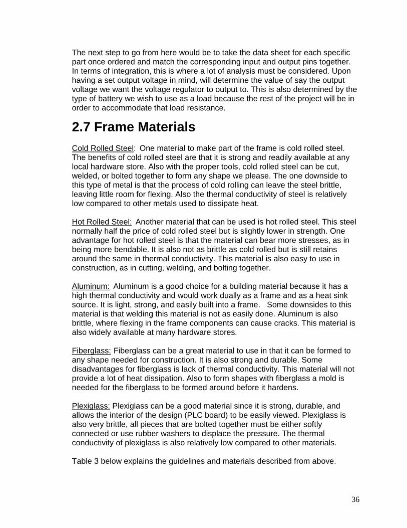
36
The next step to go from here would be to take the data sheet for each specific part once ordered and match the corresponding input and output pins together. In terms of integration, this is where a lot of analysis must be considered. Upon having a set output voltage in mind, will determine the value of say the output voltage we want the voltage regulator to output to. This is also determined by the type of battery we wish to use as a load because the rest of the project will be in order to accommodate that load resistance.
2.7 Frame Materials Cold Rolled Steel
: One material to make part of the frame is cold rolled steel. The benefits of cold rolled steel are that it is strong and readily available at any local hardware store. Also with the proper tools, cold rolled steel can be cut, welded, or bolted together to form any shape we please. The one downside to this type of metal is that the process of cold rolling can leave the steel brittle, leaving little room for flexing. Also the thermal conductivity of steel is relatively low compared to other metals used to dissipate heat.
Hot Rolled Steel:
Another material that can be used is hot rolled steel. This steel normally half the price of cold rolled steel but is slightly lower in strength. One advantage for hot rolled steel is that the material can bear more stresses, as in being more bendable. It is also not as brittle as cold rolled but is still retains around the same in thermal conductivity. This material is also easy to use in construction, as in cutting, welding, and bolting together.
Aluminum:
Aluminum is a good choice for a building material because it has a high thermal conductivity and would work dually as a frame and as a heat sink source. It is light, strong, and easily built into a frame. Some downsides to this material is that welding this material is not as easily done. Aluminum is also brittle, where flexing in the frame components can cause cracks. This material is also widely available at many hardware stores.
Fiberglass:
Fiberglass can be a great material to use in that it can be formed to any shape needed for construction. It is also strong and durable. Some disadvantages for fiberglass is lack of thermal conductivity. This material will not provide a lot of heat dissipation. Also to form shapes with fiberglass a mold is needed for the fiberglass to be formed around before it hardens.
Plexiglass:
Plexiglass can be a good material since it is strong, durable, and allows the interior of the design (PLC board) to be easily viewed. Plexiglass is also very brittle, all pieces that are bolted together must be either softly connected or use rubber washers to displace the pressure. The thermal conductivity of plexiglass is also relatively low compared to other materials.
Table 3 below explains the guidelines and materials described from above.

37
Cold Rolled Steel Advantages Tensile Strength: psi 53,700 [3j]
Durable Easy to Construct Frame With Locally Available
Disadvantages Brittle Thermal Conductivity:89 W/m°C at 20°C [3j] Price
Hot Rolled Steel Advantages Tensile Strength: 43,900 - 51,900 psi [3j]
Durable Flexible Easy to Construct Frame With Price Locally Available
Disadvantages Thermal Conductivity: 55 W/m°C [3j] Not as strong as cold rolled steel
Fiberglass Advantages Lightweight
Can Form any Shape Locally Available Not Brittle Can Flex
Disadvantages Tensile Strength: 12,000 psi [3j] Requires Pre-Made Molds to Form Shapes Not as strong as Metals Price
Plexiglass Advantages Makes Interior of Design Viewable Disadvantages Tensile Strength: 8,000-9,000 psi [3j]
Thermal Conductivity: 0.2 W/m K Price Not Readily Available
Table 3: Frame Materials Comparison Table
2.7.1 Finalized Frame Material Selection

38
Cold Rolled Steel/Aluminum:
These materials are very accessible there are available at all major home improvement shops. They can also be purchased online. Potential suppliers could be Lowes, Home Depot, or Ace Hardware.
We have found it to be most beneficial to incorporate two types of metals to gain the advantages of both. We will be building the main frame members from cold rolled steel. This is so that the skeleton of the frame will be strong and sturdy. We will be using aluminum paneling to encapsulate components that can receive water damage, such as the micro-controller and the dc motors. Depending on time available next semester we may use plexiglass so that some interior components are viewable, but this will mainly serve as cosmetic appeal. We have limited the selection of materials to cold rolled steel and aluminum. We have done this mainly due to availability and fabricating potential. Both of these materials we have found to be readily available at local home improvement stores. Since we personally have access to welding tools, using steel would make a great choice mostly due to the fact that we can fabricate any frame design we desire. We are also still considering using aluminum, for its lightweight potential. We still have not dropped this material because we are still unsure which solar panels we will be purchasing. If we purchase large panels we may use aluminum because saving on weight will be crucial in keeping the design mobile. Table 4 below describes the pricing for frame materials.
Cold Rolled Steel Retailers Pricing Lowes $4.99 angle bar 1 inch by 3 feet
$5.99 angle bar 1 inch by 4 feet $6.99 angle bar 1.5 inch by 4 feet
Home Depot $4.50 angle bar 1 inch by 3 feet $6.50 angle bar 1 inch by 4 feet $7.25 angle bar 1.5 inch by 4 feet
Ace Hardware $4.75 angle bar 1 inch by 3 feet $5.99 angle bar 1 inch by 4 feet $7.50 angle bar 1.5 inch by 4 feet
Aluminum Retailers Pricing Lowes $6.50 1 by 2 foot panel
$10.00 2 by 3 foot panel $15.00 3 by 3 foot panel
Home Depot $6.70 1 by 2 foot panel $9.99 2 by 3 foot panel $14.99 3 by 3 foot panel

39
Ace Hardware $7.00 1 by 2 foot panel $11.00 2 by 3 foot panel $14.75 3 by 3 foot panel
Table 4: Frame Material Pricing Table
2.8 Reflector Materials Reflective Tape:
Reflective tape can be used to create the reflection for the bottom solar panel. This tape is useful in that it is very easy to apply to a dished surface. The downfall for this material is that it is normally made to reflect light in all directions. The light on reflective tape is reflected in all directions because it is mainly used to make pedestrians or road side objects more visible to traffic.
Mylar:
Mylar is another very reflective material. It is 95-99% reflective and is also very durable. It can withstand temperatures from -72 to 177 degrees Celsius. Another benefit of this material is that it will not become fragile or golden from age [2j]. This material can be found online and is very cost effective. Mylar has been used in various applications. Some applications it is used in for example would be solar cooking stoves. Here the Mylar is used such that it reflects and condenses the intensity of the light to a single point. It is also used to boPET films in photovoltaic modules in solar panels. Here it works as a back face to reflect the light [1j].
Polished Aluminum:
Using a polished aluminum sheet can be beneficial in that it will act as a reflector and does not need support to form a curved bow for reflection. The disadvantage to using this is that it will be expensive to purchase this material. Also it will be difficult to locate this material in a form that is useable for us. Many of the products are pre-shaped to a specific use, which in turn will make it more difficult to fabricate the reflector for the designs purposes [9j].
Table 5 below shows the table for reflective materials.
Reflective Tape Advantages Cheap
Readily Available Disadvantages Weather Resistance
Durability Requires Dish to be Attached to
Mylar Advantages Cheap
Durable

40
Weather Resistant High Reflectivity
Disadvantages Requires Dish to be Attached to
Polished Aluminum Advantages Does not need a Pre-Made Dish to
Mount Durable
Disadvantages Expensive Table 5: Reflective Materials Comparison Table
2.9 Heat Sink There are many electronics that require heat sinks so that they operate efficiently. Since the device will be sitting in the sun and generating photovoltaic energy, it will need a heat sink to help the performance of the micro-controller. Although there are many types of heat sinks such as fans and water cooling. These types would prove to be counter productive since they will use the power that the solar panels will generate. We have found that the best solution would be copper or aluminum heat sink fins located on a raised bottom of the device.
2.10 Worm Gears Worm gears can greatly benefit the design in that they can make cheap direct current motors functional for use. The main disadvantage of using direct current motors is that there is no locking mechanism which inhibits these motors from holding their position when the panels to not need to be moved. Worm gears act such that one screw shaped gear spins by the motor; the threads of the gear turn the main gear cog. The main purpose of this configuration is that the gear cog cannot turn the screw gear. Worm gears can come in many sizes and price ranges based on the required uses.
2.11 Motor Controller For this project there is the possibility that we will need to incorporate a motor controller. We will need to use a motor controller because the micro controller might not be able to supply enough power to the dc motors for proper motor action. For these motor controllers we will be focusing on DC motor controllers since dc motors are the main focus for the panel actuation. At the moment we are focusing on either using a single motor controller that operates two motors, or two individual motor controllers to independently control a single motor. The benefit of using a motor controller is that they are fairly simple to use in coordination with a micro-controller. All they require is two to three input

41
commands from the micro-controller to tell it which motor to run, in which direction, and how fast. By doing this we will bypass the need of having a centralized micro-controller that needs to be able to produce or carry high voltage to operate the motors.
2.11.1 LMD18200 Motor Driver The LMD 18200 is a prime candidate for driving two stepper motors. This driver operates on a supplied voltage of 12V and can handle a continuous current of up to 3 amps and current spikes up to 6 amps. This type of controller requires a pulse width modulation input for it to control the motors. The driver also has a current sensing output, where it can determine what the load that the motor is being given and if that load is making it stall. There is also a thermal sensor built in to test if temperatures are within specifications.
2.11.2 Stepper Motors Steppers motors can also be used to actuate the panel. The main reason to using a stepper motor is that they do not have a fluid rotation. Stepper motors rotate in by breaking up the rotation into a sequence of steps, such that they have the ability to stop at a certain point in the rotation. The motors interior is also designed with teeth on the magnets and on the rotor. These teeth can act as place holders when the one of the magnets is not charged. One of the best applications for stepper motors is their use in positioning systems. They are used in positioning systems because they can easily be controlled by a micro-controller.[19j] Stepper motors are also useful in that they need no feedback to operate. These motors also have a long life since the only wearing components are the bearings. They also have great low speed torque which is what we are aiming for. The motors also cannot be damaged by mechanical overloads. Some disadvantages for stepper motors is their low efficiency. They require a large amount of power to operate. Another downfall is that they have low accuracy with rotational speed. Finally for their size and weight, they output power is comparatively low [20j].
2.11.3 DC Motor Brushed Another motor that can be used to actuate the panels are direct current motors. These motors are very basic and due to this makes them cheap compared to others. Some drawbacks to DC motors is that the brushes cause friction against the rotation of the rotor. It is also possible for the motor to create sparks from the brushes making and disconnecting on contact points which in turn can cause radio frequency interference [17j]. Another downside to these motors is that the brushes will eventually wear out and either the motor or the brushes will need to be replaced based on the cost of the repair.[16j] Another problem with using

42
these motors is that they will need a mechanism, such as a worm gear, so that they hold their place. A motor that is able to make the panels hold their place is ideal so that the design can save energy my only having periodic movements instead of constant changes.
2.11.4 DC Motor Brushless Brush-less DC motors can also be used to actuate the panels. Brushless motors have multiple advantages over brushed motors. One major advantage is their reliability, since there are no brushes used to alternate the current in the motor; there is less internal resistance for the motor to over come. Also since there is less friction there will be less wear on the internal parts of the motor. Another positive for these motors is that since there it is brush-less there is no sparking from the commutator making contacts which in turn will lower the chance of electromagnetic interferences. Also due to the design of these motors, they are self cooled by conduction. Since they are self cooled they can be completely encapsulated to become more weather resistant. One of the biggest downfalls to brushless motors is there high cost. These motors normally require a more advanced motor controller to operate them. So not only will we have to spend more on the motor but also spend more on the controller [18j].
2.11.5 Servo Motors Servo motors are another potential candidate for the panel actuation. Servo motors act similarly to stepper motors but are generally smaller in size. Servo motors are mainly used in positioning systems on smaller scale applications. They have high output power compared to their size as well. These motors also stay cool compared to other motors. Another benefit that these motors offer is that they produce no vibration from operation. One major downfall for these motors is that the brush wear is extremely high. On average the brushes will last 2000 hours of operation before replacement parts will be needed. They also will require a bit more coding so that they are tuned and stabilized in a feedback loop. If by chance they motors are used in an overloaded situation it will damage the motor. These motors also output their peak torque at high speeds, which is the opposite of what we need. Servo motors are also built such that they have a specific range that they can turn. This is done by a pulse modulated signal being sent to the motor. Also since these motors are built this way it is possible to use them as a lever or a pin pulling mechanism for our panel rotation. By using the servo motors to pull a pin and push it in, it can act as the main component that locks the panels into place.

43
2.11.6 Motor Batteries Since our motors will have the possibility to need more power than a micro-controller can supply it will be necessary to power the batteries remotely and have a secondary motor controller control this process. As long as our budget remains the same with no surprises, we will be looking for a 12 volt rechargeable battery to power the motors. We are looking at 12 volts mainly because they are proving to be one of the standard voltages required to run the actuators we are looking to buy. Currently if our budget allows we will be looking at lithium-ion polymer batteries due to there lightweight attributes. We are leaning away from more traditional lead acid batteries because of they are bulky and heavy, which will be counter productive in making the design mobile.
2.11.7 Linear Actuator Linear actuators are most beneficial when used to push or pull an object in a linear direction. There are also three main different types of linear actuators namely, screw, wheel and axle, and cam. Screw actuators are good to use when one has to push and pull an object. Wheel and axle actuators are mostly used in pulling objects based on their design. Finally cam actuators are useful when an object needs to be pushed in a specific direction. All of these designs can be used in conjunction with electro mechanical actuation. Table 6 below shows the different motors features and specifications.
DC Motor Brushed Advantages Low Cost
Availability Disadvantages Internal Friction From Brushes
Commutator Can Cause Electromagnetic Interference Will Require Mechanism to Lock Panels in Place Brush and Commutator Wear
DC Motor Brushless Advantages Less Internal Friction
Reduced Electromagnetic Interference Less Internal Wear Self Cooling Can Be Built Enclosed
Disadvantages Will Require Mechanism to Lock Panels in Place

44
High Cost Requires More Advanced Motor Controller
Stepper Motors Advantages Can Lock Into Place Without Using an
External Mechanism Long Life High Low Speed Torque
Disadvantages High Cost High Power Draw Low Accuracy with Rotational Speed Bulky
Servo Motors Advantages Vibration Free
High Output Power Compared to Size Disadvantages Requires More Coding
Low Brush Life Max Torque is at High Speed Can be Damaged from Overload
Linear Actuators Advantages Low Cost
Repeatable Position Feedback is Possible
Disadvantages Many Moving Parts, Prone to wear. Table 6: Motor Actuation Comparison Table
2.12 Microcontroller and I/O Board In the process of making a durable and hardworking design for this project will the picking of a good microcontroller. This microcontroller will be the pivotal device used in making this solar tracking device operational and able to display what we want our consumers to see about the productivity of the product. These are the basic criteria we want for being able to integrate this microcontroller into our project:
• Have enough General Purpose Input/Output (GPIO) pins from the board to be able to connect to the LCD display
• Be able to solder onto the integrated circuit board carefully and function well

45
• Have a good enough memory to functionally support the memory from the compiler instructions sent
• Satisfy and be able to withstand damage during certain weather conditions • Temperature efficient • Correctly implements finalized code
The main basis of the microcontroller in this project will be for storing and handling the data designed for the tracking, handling, and usage of the design for converting the sunlight energy to voltage and the main controlling center of the design. In other aspects, this microcontroller will act as the main processor of the device as a central processing unit would be towards a computer. The microcontroller will need two special materials for usage in our project which is a programming architecture and an Analog to Digital Converter in order to realize the important aspects required for our goal. The programming architecture will need several aspects to fully realize our goal of design for this solar powered tracking device. This includes that the microcontroller and the programming architecture have:
• Easy to use aspects through the use of learning skills • Well designed interface features • To be assembly or higher level language compatible (most likely of the
IDE architecture) • Have a plug in feature added to connect the integrated circuit board and
the computer for conglomerated use If these goals set above can be achieved then combining the programming with our microcontroller as well the project as a whole will be a natural process. We have to be extremely careful in which type of microcontroller we pick because of the pin layout and based on what kind of integrated circuit board we will get for this project. As mentioned in the LCD Display section of the report, we described how we wouldn’t need too many pins for the usage of the microcontroller. Therefore, in doing this we must get a feel for what bit amount would be successful for the design of this project whether it is of 8-bit, 16-bit, or a 32-bit microcontroller. Most likely, we won’t need to use a 32-bit microcontroller for this exact project design, but we will probably go more toward the 8-bit or 16-bit criteria. This whole analysis will be further explained in the Microcontroller section. Now the other component needed for this microcontroller that will be used in this device will be the Analog to Digital Converter (ADC). This device will convert regular analog signals like voice or other types of signals into digital signals that are displayed in bits of 1’s or 0’s to output to the microcontroller. Since a microcontroller is an electronic device it can only understand digital logic, so this is why it is important that this Analog to Digital Converter be used in this project.

46
Without this device, then tracking of our system will not be obtainable by any way. So in doing this, we can also alter how we can change these types of signals through our microcontroller for output to the device using the GPIO pins as well as the LCD display. However, the Digital to analog Converter will not have to be used in this design due to the fact that we are converting the signals from an analog point of view not a digital point of view. The main usage of the Digital to Analog Converter (DAC) uses the technology of Digital logic and circuit analysis to realize the functions of converting a system of 1’s and 0’s back to analog signals such as sounds or even normal sine waves with noise interruption. This type of conversion cannot be realized through the usage of a microcontroller due to the fact that the microcontroller can only understand directions based on assembly or higher-level systems which are only based on digital terms. Plus, our objective towards this project is to convert the analog signal of the sunlight to energy to fully charge and power a device. Finalizing the usage of the microcontroller will involve soldering the chip onto the integrated circuit board in a careful fashion. When we do this it will need to be connected into certain ports for the compatibility with our computer interface. By doing this procedure we can ensure that our final design will be able to produce the expected results that we need in charging and tracking from the sunlight. Through the usage of the Integrated Circuit Board and the usage of carefully soldering the pins together, we can get the microcontroller incorporated into the project. As a result of this project being one in which many components are being integrated together as well as the sensitivity of these components, there are many important factors to consider outside of just the physical components. We are referring to the input and output structure for instance. The input and output infrastructure is just as important as selecting the proper component for a specified task. Currently used in today’s society as well as to our disposal are two significant types of input and output structures. These structures are common amongst essentially all devices today; they are the digital and analog structure. An ingenious way to determine which type of structure should be used for a particular task is to determine what and how that’s structure’s role plays a part in the whole picture. If there is a setting which simply needs to be turned on or off, or simply needs no room for adjustment, either it is this or that. This type of input or output is optimum for a digital type of signal. Common digital types of devices are push buttons and switches etc. In regards to our project at some points we desire to have settings that can be turned on or off, for example controlling when the charging battery of the project has reached its maximum capacity and we want to be able for the machine to know that once it has exceeded a particular value, it should shut off. In terms of hardware programming it could be the same as viewing the difference between a 0 and a 1.

47
Analog signals however are a different story. Examples of analog signals can be those of volume controls or highly adjustable devices. Analog signals are able to be fine tuned, and reach a particular value the user demands. Analog inputs and outputs are also very important to this project as well. An example where an analog signal may be used is when controlling the actuators, say we do not want the angle of the actuator to be at 0 degrees, but at the same time we do not want the actuator to be at 90 degrees either. There must be some sort of common ground, in this case, 45 degrees. An analog input could be one that would allow us to adjust the actuator until we reach a particular degree of our desire. As seen from this once the types of inputs and types of outputs are determined, this will also help us to decide on a microcontroller part because some micro controllers have more analog pin inputs but another may have more digital pin inputs. For example, the arduino had more input pins than most of the other microcontrollers, so that is a positive aspect to consider. It would be preferred to have too many I/O pins and have extra than to worry about not having enough pins. Now, there have been many types of microcontrollers that were looked into for our project, one of which was the PIC18F87J93 which was mentioned in the LCD Display section of our paper. We are going to go into more detail on how this microcontroller was very unique. As we mentioned before, this microcontroller had the useful duality of having the ability of being a microcontroller and display at the same time which could save a good amount of time in having to solder and build. Plus, this microcontroller was already incorporated onto the Integrated Circuit Board at the same time which was the reason for the price of $150 on www.microchip.com. This website has many useful microcontrollers as well as other types of devices that are useful for building and designing an electronic device. This microcontroller had the certain capabilities [4]:
• Analog to Digital Conversion • 80 pin count • Uses a C compiler for programming the board • Works in a range of 2V to 3.6V with the Display • Works on low voltage
Another type of microcontroller that was looked upon was that of the PIC-24 series. This is a 16-bit microcontroller that is also sold on www.microchip.com. The exact name for this microcontroller was called the PIC24F04KA200 which also is like the PIC18F87J93 in that it is a microcontroller mounted onto an Integrated Circuit Board with an LCD display that has limited display capabilities. This microcontroller had only a few differences in the usage of a sleep mode since this microcontroller has low power consumption as well as normal temperature operation range. This microcontroller has more data storage in comparison to the PIC-18 series also in the fact that the PIC-18 series is an 8-bit microcontroller whereas the PIC-24 is a 16 bit series.

48
This series also has an Analog to Digital Conversion as well as uses an instructed C programming architecture as well [5]. This entails that most likely the microcontroller will either be involved with a C programming type since most microcontrollers are using more of a modern approach methods nowadays instead of the old assembly type architecture that was commonly used back in the day. This doesn’t rule out the method of using assembly language as well. In addition to a microcontroller, we have also looked into the method of finding an Input/Output Board (I/O) to help in our search for a microcontroller. Through this method we have to look for a microcontroller that will be able to accompany all our needs. These needs include:
• Having enough wiring for all our components • Having enough voltage regulation to handle charging our products • Being able to connect to our computer for code input • Able to have enough data space for our project
Arduino Boards are another viable option in which we have to implement within our solar circuit. Arduino boards which is extremely new to us, represents new 8 bit technology which works similar to an FPGA board. One positive thing we noticed about Arduino Boards right off of the start was their physical size. Most Arduino Boards are extremely small in size when compared to FPGA boards as well as PLCs. These boards are also very reliable in the connectivity sense because they use either an RS 232 serial port or even usb cables. One factor we previously determined was the use that we were mostly likely going to use a logic device with programmable flash memory. Arduino boards by default now come with that flash memory already distinguished as the primary type of memory to be used. Even though the physical sizes of most Arduino boards are very small, they still boast quite an array of practicality. This can be seen in the amount of input output ports there are on these boards. Most Arduino boards range from 14 MIMO pins, all the way up to 54 pins altogether. Another interesting component of the Arduino boards is the type of programming that is implemented within them. The Arduino boards use their own type of programming. The programming used by these boards is actually a style extremely similar to C and C++, this is good news to us seeing as how we have all taken a few programming classes and at least can understand the basics C programming. One unfortunate consistency with these Arduino boards however comes to that of efficiency. The arduino boards were created in such a fashion so that they are very easy to use, even for those unfamiliar with micro controllers. Unfortunately there is a trade off, the lack of efficiency. One who is more experienced with micro controllers would be able to devise a method and choose a way of navigating around this obstacle. Seeing as how we are fairly new to this new technology, depending on how sever the inefficiency truly is, the arduino board could still be considered for use in our project. Another very appealing aspect about Arduino boards however is that of the extremely low input voltage. Most arduino boards only require about 3.3 volts in order to operate, which is much lower when compared to other methods.

49
Another exciting feature which the Arduino Boards are capable of producing is pulse width modulation. Some of the things pulse width modulation is good for is, driving an infrared LED for a remote control. It can also provide variable speed controls for motors, and can even provide an analog output if the digital output is filtered. This analog voltage can be anywhere from 0 to 100% depending on what is required for the output device. Pulse width modulation is the act of taking a signal or input, and turning the input or signal on or off, or from one extreme to the other extreme at a rapid pace such that an equilibrium steady level is attained. In looking at this criterion, we looked into many I/O boards. Such examples include the Arduino series such as the Arduino Duemilanove Atmega168 and the Arduino Mega 2560. These two I/O boards were good candidates for this project. Both of these products are sold on many websites such as www.ebay.com and on www.trossenrobotics.com for a reasonable price depending on the shipping arrangements. The Arduino Atmega 168 had certain features that made it an interesting prospect for our project:
• Operating voltage at +5V • 7V to 12V input recommended voltage • 16kB Flash memory and 512 bytes EEPROM • 14 Input/Output pins
These features were very interesting for our project, but there was a predicament with how much data storage and pin input will be available for our design from the microcontroller to the project as a whole since we will be needing more wiring on the I/O board for wiring not only to the LCD display but to the DC motors, switches and other components that still need to be decided upon. We must also decide on another microcontroller to control one of the type of motors that we decide on using whether it is of a stepper motor, DC motor, or any other type of motor. This motor will be responsible for giving the project the ability to move in certain directions which it is supposed to accomplish in the long run. Most people would be wondering why we would need different types of control in our project. This response can be solved through the application of needing something to help produce an output to the system as a result. Without a motor moving the system through the use of a battery, the system will not be able to charge anything at the same time as well. Finally, after careful consideration, we have considered a microcontroller to add on as a prospect to use in our project. This one we have considered is to go with the Arduino Mega 2560 I/O board for our project. This I/O board has some of the same features as the Arduino Duemilanove Atmega 168, except that it has 54 Digital Input/Output pins, it also has a Bootheader which is an add-on to the device that allows us to upload software coding as an update to the old coding without having to constantly change it through going through our old code.

50
In addition, this I/O board also has a 256kB of Flash memory and 4kB of EEPROM which is sufficient for our programming input for our project. This I/O board ranges in price from $60+ depending on how many we buy. Figure 20 displayed below from www.sparkfun.com shows a picture of the Arduino Mega 2560 and its pins (A0-A15 as well as Reset, 3.3V input, 5V power supply, ground, voltage input) and even the microcontroller, reset pins and other specs such as the DC connection and the USB connection to the computer that we may considered for our project.
Figure 11: Arduino Mega 2560 I/O Board, printed with permission from
Sparkfun Electronics [6]
2.13 Panel Sensor There are other features that must be included in the design of a solar tracking device. Another one of these features is the usage of a panel sensor which will be a pivotal point in the design of this project. This panel sensor will need to be able to do a few actual realizations. These realizations include:
• Being able to sense the amount of load from the panels to incorporate the angular coordination
• Having good mounting capabilities • Being able to fulfill the tracking skills of sensing whether or not the panels
are working correctly These devices can range in size from the size of your palm to the size of a penny. This makes the device a good feature depending on how big you want to make the solar powered tracking device, but in our case we would be looking towards a panel sensor that would be not too small but not too big either as we are looking into having a decent sized solar panel ranging in the $100-$200 range. So in this case it would be of a medium size since we want this tracking device to be able

51
to move on its own in direction, angle, as well as in its charging capabilities. This device as we said before needs to be able to be used in different areas not just in one area like a solar powered farm. The panel sensor need to be chosen carefully as well as the other components since depending on the weather circumstances can greatly affect the processing power of this sensor. Just as any other device, we have to consider the long-term advantages and disadvantages so that we don’t make any errors when it comes to incorporating this device onto the solar panels. The way that the panel sensor will work in our device is that we will end up combining the device with the solar panels. This in return will make the panel sensor one of the main components in charge of directing us towards helping the actuator move the solar powered device in the right direction as well as not to make it take on too much load that the device will not be able to support itself, thus becoming an unstable system. This process will take some time to accomplish in the fact that the calibration must be done correctly through careful analysis within the design. The actuation methods will be discussed within another section of the paper. Another consideration to consider towards the picking of the size of the solar panels will be the way they will be connected into the project whether they are connected in parallel or in a series combination. Most likely, we have been leaning towards two normal sized solar panels connected in series with one another, but this is still being considered for review as we are gathering more and more results and research for this project. Within the design approach to this project we want the panel to be able to be easily mounted into the system whether it is through a soldering process or any other process used to connect the two devices together. The types of panels that are chosen for us will help us to determine whether or not we will need a lot of panels or just a few panels. We don’t want too many panels due to the fact that it would just be not useful to us. Another consideration that we have considered for this project is the usage of a voltage sensor that will be used in place of our panel sensor. What this voltage sensor will need to be able to do is the following:
• Connect to the pins on the I/O board that we have decide on • Be easily available to accompany the amount of voltage needed to power
our project • Have a good response time in relation with the operation of the project in
general Pretty much what this voltage sensor will do is to regulate the amount of Alternating or Direct Current (AC/DC) voltage levels. Through this sensor, it will need to be linear because there will be a signal that will need to be outputted

52
through the voltage input of the circuit. Once this is accomplished, then there will also need to be a consideration of sensitivity in mind when dealing with voltage sensors. When we looked into different types of voltage sensors, the sensitivity is really important because it will determine the types of conditions that this sensor will work in. So in analysis of this voltage sensor there will be an importance of signal processing for this kind of working environment. Through this also, we must take into consideration the amount of noise that will produced through our project because we don’t want too much noise interfering with the process of the output of the project and since this project will be used out in different places, we need to definitely consider the different factors depending on where we test this solar powered tracking device. Accuracy will also be a consideration for this sensor as well because it will need to perform well in conjunction with our display as mentioned in the LCD Display section of the paper. This display will connect to the board as well as the board connecting to the Voltage Sensor which will be used for our displaying purposes for tracking the voltage inputted and outputted. What will need to also happen that was determined through our group is that we need to display the voltage to the LCD Display as I mentioned before. We plan on probably getting a DC voltage meter and soldering the contacts onto a circuit that will be most likely of a voltage divider which will be on a breadboard. Through this method, there will also need to be a process of connecting the voltage displayed from the voltage meter through the microcontroller program which will be connected to our Display. We have decided on trying to find a way to create a formula to be converted to code in whichever compiler we decide on using and then finally having that result for the voltage transferred to the outputted display. The Digital Voltmeter will be used within the design and even though it will be able to display readings, it will serve as an alternative device used with our project in order to make sure that our readings measured in the project are accurate when using the viewable LCD Display. The hard part of using this device with our project is finding a Digital Multimeter that will be able to have wires connecting to our I/O board for the microcontroller. With this consideration it is also important to have a plan for how to exactly connect these components together. A Digital Multimeter that we have looked into is the following but I won’t go into detail too much on them. One of them is the Digital Amp Ohm Voltmeter made by CenTech. This Digital Voltmeter does all the normal considerations that you would see in a laboratory such as AC/DC voltage and current, measures resistance and has a battery test. This product we have looked at is displayed on Amazon.com for about $9. There were other types of Digital Voltmeters, but we decided on just finding a cheap one that will be able to support us in most of the

53
details that we need for our LCD Display to be able to check our accuracy with the product. In addition to the research on how to connect the circuit for the voltage divider is the fact that we will need to look for the components required for this experiment. Through looking at certain websites, some of these people have used an interfacing connection of using an LCD Display with a PIC microcontroller as well for this connection. This makes the possibility of choosing our microcontroller that much more important to us in the long run. There will need to be certain types of components used in this project. For starters, we plan on using a 1N4148 diode as our component as well as the combined photoresistor that we plan on buying as displayed in the section of the paper on Solar Sensors. Also, we will have to look into which type of resistor and capacitor value will need to be amounted with our circuit. This will be implemented using a breadboard which will connect our wires, LCD Display, and our I/O Board with the microcontroller. There is no guarantee that the accuracy will be fully correct with the connection of the Digital Voltmeter to the microcontroller. The factors to consider are the following:
• Resistance from the Digital Voltmeter to the LCD Display can alter our output
• Noise can affect the amount of reading accuracy • Depends also on how the machine we connect the device to will read the
data amount for reprocessing to the LCD Display All of those factors can hurt the amount of output to the display. As we have seen from certain websites that have displayed the usage of having a DC Voltmeter connected to the microcontroller, we have seen that the data accuracy is off by a little bit, but when comparing most values there is a case of there being error in calculations as we have seen through the use of our lab classes. In these other projects, they implemented a big DC Voltage Meter but in our case since we are looking at our design for cost-efficiency, we will need to look into a smaller type of Voltage Meter. The main advantages of using a panel sensor are the fact that this will be that of learning more about distinguishing between accuracy and precision when dealing with the final calculations of a device. Also, another advantage of using this voltage sensor will be finalizing the energy consumption of the device thus being able to let us know how much power is needed to operate the device as well as telling us how much energy is being supplied in order to charge the devices that we want to be charged.

54
The disadvantage of using this voltage sensor is the lack of knowledge on how to connect the device carefully to the microcontroller. As mentioned before, this device must be connected in a certain fashion along with the right amount of components in order for it to work. One mess up will ruin the part and we will have to start over again from reordering the parts that are destroyed in the process.
2.14 Programmable Logic Controller The PLC or “Programmable Logic Controller” is a very integral portion of our senior design project. According to word iQ.com, a PLC is “a small computer used for automation of real-world processes, such as control of machinery on factory assembly lines.” Most PLC’s used today are in electromechanical systems. Upon discovering the basic definition of what a PLC is and what it does, we knew right away that this would definitely be something extremely beneficial to our senior design project. As seen earlier, our senior design project is one that involves the movement of a solar panel towards the most concentrated area of solar discharge. In order for the solar panel to track where the sun is concentrated the most, a few things are needed. The first clearly is the solar panel itself, a good quality solar panel must be used, one which will be able to handle the amount of solar energy which we will be dealing with in our own project. Another important aspect of the project is that of the solar sensor. This solar sensor will essentially let the user and also the system know where the most sunlight is coming from so that we and the system can adjust accordingly. Even though these are two very important aspects which must be addressed when dealing with our solar tracker, there is one key element missing. This element is that of the interface, or the system which will essentially be used in order to link these two key components together. This is truly where the PLC comes into play. As seen in the previous paragraph, it is possible to understand why the PLC plays such an important role. PLC’s in general have a common operating structure. They are considered to have bounded “MIMO” stability. The term “MIMO” refers to multiple input multiple output stability. This aspect of PLC’s works wonderfully for us because we will need a controller which will be able to have an input such as light or heat intensity, and can then produce or determine a proper output result, for example move the actuator such that the panel is moved 5 degrees to the left, depending on what the input stated. Most PLC’s the input output structure is connected to either some type of sensor, actuator, or another corresponding piece of equipment capable of either measuring, or motion. When looking for an appropriate PLC controller for this project, it is important to consider the amount of memory instilled into the controller itself. The more memory, the more inputs and outputs the PLC will be able to interpret and produce. Another aspect in which the input output structure of the PLC can be used is within the data. This same input output format could be used in the sense where if say the power was an input, the plc could be set in such a fashion so that if ever say 3 watts of power have been attained for example, the output

55
result would then be send this corresponding data to the memory module. One would assume that such a phenomenal product, with so much multitasking capability must be a very sensitive and delicate piece of machinery. Well most PLC’s today are actually extremely durable. PLC’s now are designed in a way in which the important circuitry is protected and even the ports so that it can withstand extreme heat, cold, dust, and even moisture. The communications and human interface for a PLC is pretty diverse. As seen earlier, the plc is able to say write data to a specific source if a specification has been met. All PLC’s have communications ports on them which can then feed data directly back to the main computer or store place. This is extremely convenient because now instead of just saving data on its own, and then having to relay that data to the computer via memory card or usb stick, the data can traverse freely to a credible location. In terms of the human interface, there are also a rather varied amount of options. One could have the results sent back to a screen, whether it’s on the computer or to just a monitor in which it could graphically display the results. The human interface could even be as plain as just sending text or important numerical data back to the user, in a simple fashion. With the rise of technology today, the human interface portion can also be quite in-depth, say for example if we wanted to use a touch screen monitor to keep track of our data and create real time graphs, or even something like a manual override, all of this and more would definitely be possible with a touch screen interface. The downside to this interface however would be not only expensive parts, but also the amount of programming needed to design such a thing. It is quite in-depth. The next portion of the PLC that must be addressed is definitely one of the most important internal aspects, the programming. The whole concepts of PLC’s are pretty new, therefore there isn’t one programming language or method which is considered to be the standard. The general idea behind PLC programming is actually what we learned in digital systems. It involves using Boolean algebra and logic to determine if this and this happens, then this will occur. Usually simple 0’s and 1’s can therefore be used in order to describe the logic. In all actuality there are about 5 commonly used methods of programming this device. These methods are, the FBD or function block diagram, the LD or ladder diagram, structured text, IL or instructions list, and also the SFC OR sequential function chart. The first type of programming mentioned is the function block diagram. This method of programming involves using blocks with tasks or steps described in each, then arranging the blocks in such a fashion, either left to right, down to up, or an order of your choosing where the blocks would be connected to each other in the order in which you wanted the tasks to be performed. This is clearly the simplest of all the programming languages since essentially you can see easily what is being represented by each block and also how it corresponds with another block in terms of timing. The downside with this type of programming though is that things do have to by systematic, one at a time, so not multifaceted

56
steps are allowed. In this type of programming there are also many axioms and symbols used in order to describe some more complicated processes. The next type of PLC programming was that of implementing the ladder diagram. The ladder diagram is very similar to that of the FBD diagram, only that in the ladder diagram, electrical schematics are being used. This method of programming is the most common because things happen in a sequential manner, similar to that of a ladder. In order to traverse to the next step on a physical ladder, previous criteria must be met, that’s exactly how this method of programming works. Ladder logic can represent Boolean logic very clearly, for example. If one rung on the ladder had the variables X and Y and we wanted to program a function that would only occur if both X and Y were above a certain value, we could then program X to be anded with Y, and once that happens, it can traverse the ladder, or else it would remain at its current state. Another type of PLC programming which is available for us to use is the structured text method. Structured text is considered to be a high level programming language very comparable to Pascal. This method of programming has its advantages and disadvantages. The most common advantages of this style is that it is able to represent multiple logic extremely well, therefore making it widely accepted in the controls systems field. Some other advantages of this style of programming is that since it is considered to be like Pascal, it is very for most experienced programmers to learn, and also that fact that the code can be created in any text editor. On the other hand however, for us a significant disadvantage with this style of programming is that we’re unfamiliar with the Pascal language, therefore making things a bit more difficult as less experienced programmers to be able to just pick up a new language and manipulate it for our situations as we see fit. The next type of programming available to us is that of the Instructions List or IL method. The instructions list programming method is one of the methods learned throughout our courses here at UCF. This method of programming is very similar to that of assembly language programming. It involves physically listing a set of operands, and opcodes within a function and executes the code in descending order of the list. When comparing this method of programming to the others previously discussed. The IL method is clearly the easiest text based programming method. Although it is the easiest, that does not necessarily mean that it is the best method. There is no need for a certain syntax much like how the structured text method implemented. So this is definitely an advantage. A disadvantage with this method of programming, however, is that for long codes, this method is very cumbersome, it doesn’t look as visually appealing as the other methods since it really is just lines of text listed underneath each other. The final type of PLC programming that we have the option to use is that of the sequential function chart. The sequential function chart programming method is a purely graphical method. It is similar to that of the FBD type of programming, only on a more block and visual level. The detail associated with the FBD

57
programming structure is absent in this one. The SFC programming however is very easy to understand, and is a very organized structure of programming. A downfall to this type of programming though is that in order to create, use, or edit something using this method, we would have to get involved with some complicated software. For our solar project, we are analyzing all aspects of the project, including cost, therefore not making this the favorite method seeing as how a lot of money would have to be spent with this method. Upon careful analysis of not only understanding what a PLC is, but also learning more about its structure, uses, and ways to program. We are then able to analyze how this peripheral can be related to our project and pick an appropriate device to use. For us, we analyzed our inputs to be that of the solar panel which is exposed to the sun, we are also going to have inputs such as voltage, power, and efficiency. Our PLC could then display these results and react accordingly. In conclusion, the PLC essentially serves as a vital relay of information for our project. If something goes awry with this tool, the accuracy of the rest of the project is at stake. The logic behind the PLC is easy to understand and can even be implemented numerous times incase we wanted to expand the project from our small scale to a much larger one simply by just cutting and pasting the logic implanted in this project.
2.14.1 PLC Coding Languages Ladder Logic:
One type programming language that can be used is ladder logic. Ladder logic is very useful in that most programmable logic controllers can operate off this language. This language also has the capabilities to take inputs, analyze them, then relay the necessary information to displays, motors, or other outputs.
Traditional Logic:
Another type of programming language that is possible to use is traditional languages. These would incorporate languages such as C, C++, or software that is supplied with the programmable logic controller such as Arduino. These languages have a been widely used and the more simplistic code is easily learned. It is widely available and can be very cost effective in terms of software. It will also save on work time since we have previous experience using such languages.
State Logic:
State logic is a relatively new way of controller. It takes advantage of gate states to achieve what a micro-controller is supposed to do. Using this method can be extremely cost effective in that the micro-controller will literally be built by cheap gate chips that are arranged such that it will control the direction of the solar panel. Although this method can be very advantageous the disadvantages rank rather high. It can be very time costly to derive the gate sequence to control the device. Certain tasks cannot be obtained through this method such as storing data.

58
Manufacturer Supplied:
It is highly probable that the the micro-controller will have a programming language supplied with it or made exclusively for its purposes. This is beneficial in that the programming will be tailored specifically for the micro-controller making the coding do's and don'ts easier to pick out. One downfall to this is that more than likely the coding style will be different from what we have experience with.
Table 7 below shows the different types of logic used with programming architecture.
Ladder Logic Advantages Widely Used Programming Language
Vast Amount of Learning Resources Low Cost Software Reliable Easily Testable Simplistic
Disadvantages Requires Programming Knowledge *Not Similar to Other Programming Languages
Traditional Logic Advantages Widely Used Programming Language
Vast Amount of Learning Resources Low Cost Software Reliable Easily Testable Sometimes Supplied With a PLC
Disadvantages Sometimes Requires More Expensive PLC Board to Use Code Can Become Complex Some PLC Boards are Not Compatible
State Logic Advantages Is Not easily Implemented
Requires Large Amounts of Time to Derive Design Not a lot of Resources
Disadvantages Is Not easily Implemented Requires Large Amounts of Time to Derive Design Not a lot of Resources

59
Manufacturer Supplied Advantages Tailored for Chosen Micro-controller
Makes Language Selection Easier Disadvantages Learning New Language
Learning Curve Can be High Table 7: Coding Language Comparison Table
2.14.2 Arduino Coding Language At the moment we have concluded on using the Arduino Mega circuit board. It is a premade with an I/O, micro-controller, and has a USB connection for programming. One main reason for choosing this controller is that its coding language is supplied by the company and is very comparable to C++. We have found this to be extremely beneficial in that we have all had experience with C/C++. We will also be able to have teaching instructors on campus help guide us with coding since it will be similar. The code itself is very simple, for most cases it will only need a setup command at the start of a program to initialize settings coupled with a loop that will operate until the board is turned off.
2.15 FPGA Information Although the programmable logic controller portrays an excellent way to associate our inputs with our outputs for this project that does not necessarily mean that it is the best way to do so. There are three significant factors which really deters us from using a plc to organize our input output structure. The first issue is that of the input voltage. The whole point of our project is to find a way to utilize the world around us in an economical and environmental sense to better the world around us. We are looking to use as little energy as possible in order to attain the greatest amount of possible energy so that we may utilize that energy and power in any which way we use, in this case to power our batteries and devices. The programmable logic controller does promote a very practical method of associating our inputs to our desired outputs. The plc itself however needs some input voltage, or power, in order to function. We wouldn’t mind if the programmable logic controller only demanded a very small amount of power, but most programmable logic controllers on the market today are large scale. Whenever we were considering the PLC’s we noticed that most had input voltage values of 12 volts and 24 volts. Those voltage values alone exceed the amount of voltage which we even expect to get out of this project. This would therefore reduce our efficiency to zero seeing as how our output voltage wasn’t even enough input voltage to even fully power our own device.

60
The second detrimental factor of the programmable logic controller is the size of the controller itself. Most PLC’s that we found online were for large scale permanent devices. Our portable solar project is considered small scale as compared to most, but it most definitely is considered a portable device. We are working with the mindset that our device will be able to be used anywhere in the world. It would have its own tracking system for sunlight, wherever one was in the world, so as a result of the degree of portability for which we are trying to attain, something this detrimental to us comes at much too great of a cost. Usually with these devices, size and weight go hand in hand, essentially meaning that because the devices are so large, they are also very heavy which takes away from the portable aspect of the project for which we are trying to achieve. The third major detrimental factor when using a programmable logic controller is that of cost. The idea behind the controller is ingenious, there are many applications in today’s society where it can and is used fluently. However, another goal with our solar project besides efficiency, and portability, is that of cost. Unfortunately, quality and cost do go hand in hand. A cheaper project built with cheaper parts will not last as long and also will not give the optimum results. On the other hand a project built with the best parts will indeed give the best performance, but unfortunately the project at that time is impractical to most because it cost a fortune to construct. There are many other options to overcome these obstacles however, the first of which is an FPGA board. The FPGA which stands for Field Programmable Gate Array, is another more reasonable option we can use in order to bring communication between the MIMO system of our project. The logic located on the FPGA board may either be simple for example, one task at a time. The beauty about this board though is that it can also do advanced complicated logic as well. Earlier with the ladder logic, we saw that we could essentially only perform simple logic function because things would occur in a “ladder” format, or sequential fashion. One step could not be completed until the previous step had been finished. With this board however, not only could we implement that similar form of sequential logic if need be, but we are also able to do complex logic, and simultaneous at that if we needed to. The next aspect to observe about FPGA’s from this standpoint is the type of memory we want to implement within our FPGA. The available types are SRAM, Antifuse, PROM, EPROM, EEPROM, Flash, and Fuse. SRAM stands for static random access memory, meaning that this type of memory is programmable and re programmable, but needs another device in order to essentially function. The Antifuse type of memory is that of a single writable memory. It cannot be changed or modified once it has been written. The next type of memory available to us is that of the PROM. PROM which stands for programmable read only memory, this memory can be written to, but that’s it. It is able to be written to and then just observed from that point further. EPROM technology is also available to us, this EPROM is referring to erasable programmable read only memory. This

61
memory acts very similar to the regular PROM only that in this case, within a certain time frame, we have the option of going back and erasing the memory. Although this sounds like a practical solution, unfortunately the only way to erase memory in this state is by using ultraviolet light. This may not be the best method for using seeing as how we would have to go out and purchase this ultraviolet component in order to get this part fully functioning. The next type of technology available to us is that of the EEPROM. EEPROM refers to electrically erasable programmable read only memory. This memory is the best type of memory but unfortunately as seen earlier, quality comes with a price, also making this technology one of the more expensive ones. The next type of memory which is available is that of the Flash technology. Flash technology most likely will be the one we use, not only is the technology effective, but it is cheaper because it is cheaper and easier to manufacture. Essentially flash has the same result as EEPROM but the downside is that it is not as dependable as EEPROM. On the positive side however, even though it is not as thorough, it still does work very well overall, leaving a good balance between cost and performance, something we are definitely looking to incorporate within our very own project. After analyzing the many different types of memory and technologies available to use on the field programmable gate array, we then have to devise a way to instruct the panel on what instructions it should execute. There is a bridge between the physical implementation and the simulation. This gap is usually crossed by programming of some sort. There are many different types of programming available to us. There are HDL languages, for example the ones we learned in digital systems, Verilog and VHDL. VHDL is more of an abstract language which the computer / devices devise on its own. We did learn quite a bit of verilog and its infrastructure, therefore if we do choose this route of programming, we would most likely use Verilog as our primary language. Another result of being very familiar with verilog ourselves is that we know how the language matches up to the schematic method. The schematic way of handling tasks would be very practical to us, but to a regular consumer, that method would require too much effort and work, so programming would be the easiest solution when thinking of the goal of the project and the consumer. The schematic version of implanting the logic uses the mindsets of flip flops, clocks, and just regular Boolean combinational logic.
3.0 Testing
3.1 Equipment Testing Mainly with this project, there is the possibility of having a lot of components with the device in order to make this project work, which is why we must properly test our projects conditions in order to satisfy our assumptions made. These assumptions include:

62
• Testing within the conditions of weather (storms, rain, or excessive humidity)
• Have a long time period durability • Be able to generate the amount of power designated without destroying
the system • Have the ability to charge the devices designated by our group (battery,
phone, etc.) Through these guidelines, this is what we will base our testing on. First of all, we will need to buy our parts and once this is completed in a timely manner during our next semester in Senior Design. We must make sure that each product bought matches the specifications adhered to from the datasheets, websites, and information acquired for our project. This will help us to be able to know what will be important things to consider when working with our components so that we don’t mess anything up. The perfection of this project will be displayed through the use of our LCD Display which will show us our accurate results from our microcontroller output. Through our use of this product it will help us to further check into whether or not things are working correctly or not with our device so that we can fix it for later. In our project we will be charging two types of batteries: AA battery and a car battery. Through the use of both of these ready to charge components we will need different types of voltage regulators for this type of charging. One will need to be of the 78XX series for the AA battery and the other will need to be of a big voltage regulator. The main reason why we are deciding on using a battery as a first test for charging in our project is due to the ability to test smaller and bigger components of the same caliber in order to see what the difference in charging these two devices will show to the final result of the project. If we can charge a car battery and a regular battery, then there is the ability to charge other devices as well with further consideration into the aspect of what needs to be charged. The reason for the differences in voltage regulators will to not exceed the needed voltage required to charge these devices. Failure to do so will result in dangerous consequences that we do not want to deal with. Figure 21 shown below from http://www.8051projects.net shows the 4 bit connection that will be used for connecting the LCD Display for our testing of this part. Using this design approach will be a much easier approach than using the other type of mode connection which is the 8-bit mode connection which requires a lot more effort on production.

63
Figure 12: LCD Connections in 4-bit mode, printed with permission of Ajay
Bhargav at Rickey’s World Microcontrollers and Microprocessors [8] Since we will need to test our LCD Display in 4-bit mode, this means that ports D0-D3 on the LCD Display won’t be needed for our design so they will be grounded as well as the Read/Write line. The main lines that will need to be used in our project for the 4-bit mode display will be D4-D7 as well as Enable and Register Select. These portions will be connected to the microcontroller I/O board as well as the VCC, and VEE
. The only other portion of the LCD that may need to be connected is if there are any other pins enabling the backlight display for certain types of weather conditions in which we cannot see the display clearly.
Testing within the boundaries of 4-bit mode will be essential for the use of the LCD production output in that it will send the data out in sets of 4 instead of having to send out the information to be displayed at one point. Through our testing, we will need to take the amount of data being sent into consideration so that we will be able to know what letters are being sent through our circuit to the display. Testing for our microcontroller will definitely be of careful consideration since we do not want to go below the +5V input to operate the device. We definitely need the regulator also to keep the amount of voltage stable with the microcontroller so that we don’t output too much and fry the I/O board. Figure 6 below shows a schematic of the connections for the LCD Display, microcontroller, and the photoresistor all in one place. Pretty much what will happen with these components will be that the photoresistor will be connected to the circuit via pins 0 and 1. Also, the pins for the VDD, VEE, register select, and Enable will be connected via the pins for 5 volt supply, voltage reference, the other 3.3 volt line, and the reset pin as well. Starting from the rightmost pin to the leftmost pin shows the following pin assignments for the LCD Display: VSS, VDD, VEE, R/W,

64
Enable, and D0-D7. The portions on the photoresistor signified by 5V and 0V mean that those portions of the photoresistor will be connected to the 5V voltage port on the microcontroller and the other portion will be connected to the ground terminal of the whole circuit. When this design comes together it will have to be designed to fit all these features of the schematic. Figure 22 below show this actual prototype.
Figure 13: Schematic of LCD Display connected with Photoresistors and
microcontroller board The types of equipment that will be involved in this project include the following components:
• LCD Display
•
: Used for the monitoring of the information to be tested such as the voltage, current, and power efficiency. Photoresistors
•
: Material element that will be determined by the group. This component measures the amount of sunlight from the windows on top of the component. Very fragile component. I/O Board
•
: Board that will be the base tool for our control of the project since it will deal with the microcontroller, the resistors, as well as any other wired components needed for connections. Breadboard
•
: Will be other important tool used in our project that will be for connecting the different tools such as the resistors, voltage regulators, and even other wires. Microcontroller: Processing unit that is critical for the working functions of the project. This component will be the main control unit responsible for

65
making the output produce its results through the use of a programming architecture as well as producing results displayed to the LCD Display.
• DC motors
•
: Component responsible for directing the amount of flow current and charge through the circuit designed in the project. Based on which way it is turned whether clockwise or counterclockwise will determine which type of current is being generated. Voltage Sensor
•
: Designed task of being a component to check our testing results through the use of its measurements to check for any errors that occur in the design of the project. Batteries
•
: Responsible task of being used to not only charge our DC motors for operation but also for the task of being our components used for being charged by our solar powered tracking device. Programming Architecture
•
: Will be used for the task of not only determining our type of compiler but to be the main transfer of information throughout the finalized design of our project. Compiler
•
: Our main instrument for making the instruction needed for the computer to operate and generate our results. The type of compiler used will be greatly dependent on what microcontroller is purchased. Solar Panel
•
: Used as an insulator of energy supplied through sunlight that will be needed to convert the sunlight energy to voltage to charge devices. The weight and size will be dependent on how much the group is willing to spend as well as how much power we want outputted. Servo-motor
•
: This motor will be used for the task of determining the amount of turning available to determine the pulse width modulation as well as the movement of the device in general through the force of this motor. Power Switch
•
: The turn on/turn off component that will be implemented along with the DC motors. Stepper motor
•
: A motor that works opposite to that of a DC motor in the fact that the motor is turned not by mechanical motion but by electrical motion. Linear actuator:
•
Device that is used to move the direction and tilt the angle of the solar powered device. This device will be used as a helping device to maximize the amount of sunlight received for voltage transfer from sunlight. Wires
•
: The main connection structure that will not only be used to connect the pins from our LCD Display to the Breadboard and the I/O board, but to help connect the important components together in a well-ordered fashion. Reflector
: Will be used as a material for reflecting a sufficient amount of sunlight unto the solar panels for efficiency purposes.
3.2 Power Testing Another testing portion that will definitely be needed to be looked upon is the power that will be supplied to the device. This portion of the testing will be about

66
how much energy will be supplied through the device to charge our appliance. The main goal of this will be to output as sufficient amount of power needed or available to the solar tracking device. The solar tracking device will be running at certain time periods, but not at all times since we are looking to have it low-powered as not to consume a lot of energy. This device will tilt itself at certain portions of the sun as to track the most amount of sunlight, but our problem lies within the confines of figuring out the best way to gather a lot of sunlight for converting that light to power but at the same time trying to not overload the device. The thing about our solar tracking device is that we aren’t trying to have it tilt and move at all angles at the same time because we don’t want too many complexities. What we want with this motion is for the device to move from one side to another and once it reaches the other side then it will tilt itself up to find where the sunlight is located.
3.3 Error Testing There is also the matter of testing the solar powered tracker when there are problems within the device that prevent it from working. These problems include:
• Photoresistor not getting enough light to work • Breadboard ports not working • Microcontroller not supplying enough voltage to the device • Device is not charging the batteries as required • Readings compared to the Voltmeter from the LCD Display are way off
The problem with the photoresistor not getting enough light to work in a timely fashion will most likely be due to the fact that the window on the top portion of the device is fractured or the fact that the breadboard port it is contained in is not working due to blockage. In this case we will need to either move the device or get a new one to compensate for this. If the condition still persists then it may be due to the fact that the photoresistor compound is not correctly suitable for the type of weather condition it is subjected to. The other problem with not charging the batteries as required of our project goals would be due to the fact that there is either not enough sunlight conversion to voltage supplied or the fact that something is wrong within the system of the solar powered tracking device. The way to fixing that problem will be to check ay wires for damage and supply any new wires if needed. Also, we will make sure to have a device to check if this does happen, especially through the use of our Voltmeter. The other big problem would be the differences in the reading of the LCD compared to the results of the Voltmeter. When this occurs, we will need to make a certain error proportion of from about 0.1%-1% which there will not need any

67
type of altering, but if the error crosses that boundary then we will need to take precaution towards this so that our readings don’t ruin our results. The last problem would be dealing with the breadboard not working correctly as specified. This could be in part to one of the ports being clogged or even burned. This problem must be fixed in order to have the whole project work due to the fact that we will have all our components connecting together through the breadboard whether it is the DC motors, microcontroller, and even the LCD Display. The breadboard will be the huge connecting hub of the device and if messed up then it will alter the response of the project. This could also be due to the fact that our design predicted for our project is not fully correct and thus it is affecting the production of the output.
3.4 Durability Testing The most important type of testing for this project will be during different types of weather conditions. This is an important factor because of the fact that the consumer will want to use this device in most areas and weather has to be a consideration when thinking about this. The device must be able to withstand most types of weather conditions. It definitely must be able to stand strong when it comes to heat since the sunlight will be our main producer of power to charge our appliances. What we will do for this is to test our solar powered tracking device for its ability to handle itself even in the rainiest of conditions, because if it can’t handle itself during those types of conditions then it won’t hold up well for us in the long run. This durability testing will test our panels to see if there are well-built for our project as well as our sensors to be able to work during these conditions even if there is no sunlight being provided to the solar powered tracking device. What must be done is to finalize our design for these types of conditions so that it won’t hinder us on presentation day. With this durability testing, there will need to be taken into consideration what type of material will be best for our testing purposes. Through the dependency of the device as well as how it performs throughout our step-by-step building sequence of this project will prove to us how well this project will hold out in future advancements. This is very important especially when we have to take other consumers into consideration so that this project won’t just work when we are testing it but for other people as well. Once our durability testing is complete, then we will be able to know that our project is stable enough to enter into the real world. The only concern as of right now is if our cost of the total project will support our amount of funding requested. The funding is also a factor that will also determine the durability of the project since the amount of funds will determine what types of material we will be able to obtain.
3.5 Frame Testing

68
The frame must be built such that it holds the components together, have two directional rotations, and supply adequate leverage for the stepper motor to turn the panel mounts. We will have to verify that the frame can have enough space to hold all the non weather resistant components as well as the panels. To do this we will double check the component's lengths with the frame’s created lengths to make sure all parts will fit correctly. To test the rotation we will make sure it has least possible rotating resistance possible. We will do this by physically rotating the mounting frame and checking for resistivity in turning it. If it does not turn we will have to check the structures measurements to see if there are any binding parts. We will also have to check to make sure the bearings or the pin the mount is rotating on is properly greased. Next we will have to test the rotational degrees of the mount. For the horizontal turn we will need to make sure it can turn 360 degrees in both directions. We will also have to test the vertical rotation to make sure it can turn from 30 degrees to 150 degrees. If either of this rotation degree tests fail we will have to check the frame to make sure frame members are not binding or stopping one another. Finally we will have to test the stepper motor to see if it can turn the mounts if it cannot turn the mount we will first have to check for frame binding and to make sure it is properly greased. If both of these checks pass we will have to redesign the frame such that the motor gains more leverage on the mount by means of pulleys or gears.
3.6 Motor Driver/Controller Testing One of the crucial parts to the design is the motor controller. In an ideal situation we will make all the necessary wiring connections and the motor driver will run as predicted. Unfortunately this situation will most likely not happen, due to this we will be deriving testing procedures to test the motor controller to check that is actions are acting accordingly to the design's needs. There will be three main parts that will need to be tested, these are; input data from the micro-controller, output data to the motor stepper, and overall motor stepper controlling performance. To begin testing the input data we will have to check the micro-controller to make sure it is correctly sending signals to the motor controller. The motor must be receiving a pulse width modulated signal for it to operate. If it does not receive this type of signal it will be impossible to operate the motor controller. So the first thing to check is the wiring on the micro-controller is connected to pins that output pulse width modulation, these pins on the arduino mega are pins 0-13. Next we will have to check to make sure the pulse width modulation input is correctly attached to the motor controller's input pins. Following input testing we will have to test output signals from the controller. Most stepper motors require four or more inputs to correctly work. For our

69
stepper motor, we will be focusing on a two phase stepper motor which will require four inputs from the controller. These inputs will be direction, step amount, sleep, positive voltage connection and ground connection. To start we will have to test the input output voltages on the board to make sure a safe amount of voltage is being so that we do not destroy the controller or motor. For our motor controller we will test to see if if is receiving a 5 volt input to operate the board. We will also test the input and output voltage that will connect to the board to power the stepper motor. These voltages will have to be between 5 to 30 volts which is the operational limits of the stepper motor. After checking that the voltages supplied to the controller and to the motor we can test the direction pin, step pin, and sleep pins. The direction pin will control the direction the motor will spin. For this we will simply give the command in the arduino software code to turn the motor in a clockwise direction. After this we will also have to give the motor controller the commands to initiate the step pin to turn the motor in a certain amount of steps. For instance, after we have had the code written to turn the motor clockwise for five steps, we will turn on the micro-controller which in turn will send the commands to the motor controller. At this point as long as the motor has power and is receiving the signals it should turn clockwise for a total of 1.8 degrees five times for a rotation of 9 degrees. We will repeat this process until we can confirm it will turn clockwise and counterclockwise for segmented and complete 360 degree rotations. The final part to test for the motor controller will be the sleep mode. The sleep mode will cut the power supplied to the motor to stop it from overheating when it is holding its place. If the motor overheats it can damage itself or other components in respect to its proximity to other sensitive parts. Also by shutting off the power we will be saving wasted power. There are three components to test to see if the motor controller is in sleep mode. First we will need to check the motor controller is on and connected to a battery. This will be tested with a voltmeter to assure that the motor controller is receiving its 5 volts for minimum operation voltage. Next we till test the voltage on the battery to check if its within the motors operational voltage. Then we will put the motor controller in sleep mode and test the voltage going to the stepper motor. For sleep mode to be on the voltage to the stepper motor must be zero. Finally another way to test sleep mode is to turn the stepper motors rotor. If it doesn't move then there is power flowing through its coils, if is does move then there is nothing powering the internal magnets and the motor controller can be assumed in sleep mode.
3.7 Stepper Motor Testing The stepper motor is on of the main components in the solar panels rotation. If the stepper motors are not operating as they should be we will need to run tests to trouble shoot their problems. The main components of the stepper motor that will need testing is the input voltage, rotational direction, rotational speed, stepping motions, and stall torque.

70
The most crucial aspect to test will be the input voltage; we do not want to burn up the stepper motor by supplying too much voltage. This will be done by using a voltmeter, testing the battery supplied voltage and checking to make sure it is within the operating voltages. We will also need to check that the ground is properly connected. If the ground is not connected the current flow will not be complete and the stepper motor will not receive any power. Next we will need to test the rotational direction and stepping motions. Testing the rotational direction is a simple matter of knowing the input direction command and comparing it to the direction the motor turned. If the motor does not turn in the proper direction we will have to return to motor connection testing and ultimately micro-controller testing to check the coding. After this we will need to test the angle of one step from the motor. We can do this by attaching a twelve inch small rod perpendicular to the motor rotational shaft and place the motor on a large piece of paper. Following this we will mark the point of the rod tip on the paper. Then we will have the motor turn one step, and mark the paper again. From here we can find the angle with the two marked points compared to the center of the shaft. If the motor turns within 1.8 degrees +/- 5% error then it is operating within its specifications. If the motor turns further than this and cannot properly go to the position needed then we will have to either get a refund or buy a new motor. The final part to test on the stepper motor is its stall torque. The stall torque is the amount of resistive force needed to stop the motor from turning. We can test this by making sure the motor can properly turn the panels without stalling. If the motor does stall we will either need to reduce the force acting against the motor or buy a stronger motor. To reduce the resistive forces we can change the frame design by means of reduce rotational friction with bearings. Also we can reduce the resistive force by giving the motor a greater leverage on the panels. To do this we will either introduce a gear, pulley, or lever action such that the motor has more torque but less speed.
3.8 Servo Pin Pulling Testing The servos on our design are being implemented such that they will push and pull pins that will lock the panels in place when the panels are stationary. Since this is a intricate procedure, testing the servo pins will be tested after it is known the micro-controller, motor controller, and stepper motors are all acting according to their designed needs. That is, the controllers control the motor properly and the motor turns to the new desired location. For the servo to work correctly they will need to be tested for accuracy. First we will need to test the servo to pull the pin out. The servo should pull the pin out when the motors are turned on and holding position. If it doesn't will we need to back track to test the micro-controller, motor controller, stepper motor, and the frame to make sure they are working correctly. Next the servo should push the pin back in after the panels have rotated to the new position and the motors are in the holding state. If the servo

71
motor has correctly pulled the pin out but does not push the pin back in we will need to check to make sure the frame rotation aligned properly and then check that the micro-controller coding is written correctly.
3.9 Actuation Test Results The final design which was implemented involved using the shader over the photoresistors. The logic behind the photoresistors as mentioned earlier involved moving the resistors until they reach a point where all four resistors have the same amount of light hitting them. This design succeeds in pointing the device in the direction of the most light. We all realize that as the course of the day progresses, so does the position of the sun in the sky. That actuated movement as described previously is designed to accommodate this trend there by always having our solar tracker in the most sun, making it more efficient than a static solar panel. Upon the completion of the design, numerous tests were conducted. We were able to test the actuated movement versus the non actuated movement through the course of a day on an hourly basis and record the wattage we were receiving when the device was and was not actuating. This figure, figure 23 it is possible to see how the actuated vs the non actuated movement not only proved the actuated movement to have a higher power, but especially during the sunrise and sunset time periods, the efficiency was much greater when compared to the non actuated movement. This test was completed using a 2.2 ohm power resistor.
00.5
11.5
22.5
33.5
44.5
Tracked
Fixed
Wat
ts
Time of Day
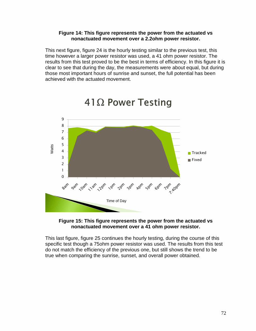
72
Figure 14: This figure represents the power from the actuated vs nonactuated movement over a 2.2ohm power resistor.
This next figure, figure 24 is the hourly testing similar to the previous test, this time however a larger power resistor was used, a 41 ohm power resistor. The results from this test proved to be the best in terms of efficiency. In this figure it is clear to see that during the day, the measurements were about equal, but during those most important hours of sunrise and sunset, the full potential has been achieved with the actuated movement.
0123456789
Tracked
Fixed
Wat
ts
Time of Day
Figure 15: This figure represents the power from the actuated vs nonactuated movement over a 41 ohm power resistor.
This last figure, figure 25 continues the hourly testing, during the course of this specific test though a 75ohm power resistor was used. The results from this test do not match the efficiency of the previous one, but still shows the trend to be true when comparing the sunrise, sunset, and overall power obtained.

73
00.5
11.5
22.5
33.5
44.5
5
Tracked
Fixed
Wat
ts
Time of Day
Figure 16: This figure represents the power from the actuated vs the nonactuated movement over a 75ohm power resistor.
3.10 Owner’s Manual Since these projects cannot be aimed at a targeted consumer, it will be necessary to produce a user operations manual. It should be noted that the design has not been built yet but that having a guidelines to follow for how it should be operated can be beneficial when we build the project. This is due to that fact that we will need to make sure the project is built such that outside users (not the designers) are able to effectively operate the device. Below we have listed the basic operation steps to operate our solar tracking battery charger.
Operating Procedure Steps
1. First begin by placing the device upright outside in the sunlight. 2. Make sure there are no objects that will be the panels rotational direction. 3. Connect the male wires from the motors, linear actuator, panels, to the
female wires protruding from the electrical case. All of the wires have been labeled so simply match the numbers to its corresponding connection.
4. Next connect a chargeable battery to the regulator connections, this battery must be 12 volts or larger.

74
5. After connecting a battery, double check the wiring to make sure that the wires are properly connected.
6. Flip the switch, which now allows power to the electrical configurations. The device is now active.
7. The device already has the program and logic built into the design, so upon it being powered, the device will autonomously turn and adjust itself to the area of the largest concentration of light.
8. The tracking movement is now in effect! 9. From here there are two options: Using a device or Charging a Battery. 10. When Using a device, first plug the device into the power inverter. 11. Turn the inverter on, and then now you are able to use your device. 12. When Charging the battery, simply connect the terminal wires to the
correct terminals on the battery. 13. Charging is now in process. 14. The display indicates the solar panel voltage, the battery voltage and also
the battery efficiency at all times regardless of which method the battery is being used, charging or powering a device.
15. Once the battery has been charged simply disconnect the charging wires. 16. Once you are finished using your device, first turn it off. 17. Turn the inverter off. 18. Now flip the switch inside of the electronics case to off. 19. The device has now been completely powered down and may be put
away into storage until next use.
3.9.1 Safety Procedure When using this device one can never be to cautious. These procedures are meant to keep the user and the device safe. It should be known that this device is capable of causing harm to an individual. Due to this, it will be necessary for the individual operating the device to review the safety procedures to reduce or eliminate any possible harm that me be induce to the individual caused by the device. Finally it also should be known that this device can cause injury through means of burns, electrocution, and eye damage.
User Safety Guidelines
1. Individuals with pace makers should use caution when connecting battery terminals. (May cause death)
2. Do not touch stepper motors or put fingers in the stepper motors gears. (May cause burns or cuts)
3. Do not short circuit charging terminals. (May cause electrocution) 4. Do not stare at sunlight. (May cause eye damage) 5. Do not operate device if stepper motors are overheating. One can test this
by not touching the motors but placing ones hand close to them and feeling heat radiating off of the motor.

75
6. Do not place fingers in front of locking pins. (May pinch fingers)
Device Safety Guidelines
7. Do not operate if motor gears are binding. 8. Do not force rotation of panels. 9. Do not charge batteries that are not within the charging capabilities of the
device. 10. Do not force locking pins in and out. 11. Handle device with care.
4.0 Design
4.1 Schematic Design Through the uses of our project research, we have decided on making a schematic not only to tell where the parts will most likely connect to, but to show how the project will connect as a whole.
4.2 Reflector Design The reflector will be situated such that it provides sunlight to the bottom solar panel. The reflective material will probably be adhered to a piece of sheet metal. This sheet metal will be bowed to form a partial cylindrical shape that reaches beyond the width of the solar panel. Thin metal rod will be welded to the sheet metal to hold and make the bowed shape more rigid. Dish If the panels are more squared shaped, we will used curved cylindrical reflectors on the all sides. One design method for the reflector would be to use a reflector in the shape of a dish. This shape would be the best to optimize the reflection surface area. This dish will most likely be made of a polished metal. Since the dish itself is metal, it will be rigid enough to hold its own shape. Another design for a reflector would be to create a solar funnel. This solar funnel will work similarly to a solar cooker, where indirect sunlight is reflected from the sides of the panel onto it.
4.3 Stepper Motor Design One of the two top choices for the design's actuation is the use of stepper motors. Although we have not concluded on the best route, we have derived schematics for each actuation's design. This is so when we do decide, the schematic plans will already have been made so the circuit can be reproduced. In figure 23 below, we have provided a simple schematic of the motor controller controlling two four phase stepper motors. These stepper motors are being powered by a DC power

76
supply and are being directly controlled by the motor controller. The motors are being indirectly controlled by the centralized micro-controller that is overall controlling the motor controller's actions. [10j]
Figure 17: Stepper Motor Schematic
4.3.1 DC Motor Schematic Our second choices for motors are using simple DC motors with worm gears to keep the panels in place when the motors are powered off. The three main reasons why we are considering using dc motors and a dc controller is because dc motors are cheap, dc motor controllers are cheap, and the DC motor controllers are extremely simplistic only requiring simple input commands for forward, reverse, and which motor to run. In figure 24 below, we have supply a rough schematic of the DC motor controller connected to the micro-controller, DC motors, and a battery power supply.

77
Figure 18: DC Motor Schematic
4.4 Panel Locking Mechanism Design For the project to be viable, it must produce more power than it consumes. The main design that we are going to implement would to have the panels lock in place while the tracking system is off. Another reason we need the panels to lock is that while it is off it is possible for the panels to be effected by the force of winds which could turn the panels. For the motors that are available to us, they have no way locking without having a supplied current. We are currently planning on using stepper motors which can hold a specified position, but this requires that the electromagnet is being energized which in turn will cause the motor to become hot. These side effects of keeping the stepper motor in place namely, current use and heat are very undesirable. This leads to a design that we believe can be used to keep the panels in place. We are going to build the panel mounting frame such that a pin can be pushed in and out of a hole that will block the panel's frame from rotating. We will build it such that before the micro-controller tells motor controller to turn the stepper motors, that it will tell a linear actuator to pull the pin out. After the stepper motors have rotated the panels to the new desired position, the micro-controller will have

78
the linear actuator push the pin in. By have a linear actuator control a pin, the panels can be locked into place and the tracking system can be turned off to save or produce more power. Also since we will be using stepping motors we can have them turn to a specific rotational degree accurate to within 1.8 degrees +/-5% error such that the pre-drilled holes will line up evenly for the pin to be placed.
4.5 Photoresistor Design For the photo resistors to work properly they will need to be situated such that the micro-controller can compare the resistivity of one to another. By being able to compare the resistivity of the photo resisters the micro-controller can accurately maneuver the frame to the ideal position that is in the immediate direction of the sun. For our design we have developed three concepts to implement the photo resistors.
4.5.1 Photoresistor Design 1 Our first design would use a total of 4 photo resistors. Out of the four photo resistors two will be used to test left right direction and two will be used to test up and down direction. We will situate the resistors such that they are on the centered on the edges of the panels. Next we will have them at a 45 degree angle facing outward from the panel. By putting them at angles the resistors will have either more direct sunlight or less, but never equal when the panel is not facing the sun. The main concept by doing this is to have the two resistors be equal to one another in terms of resistivity. By initially rotating the frame in the direction of the most resistance it will be turning towards the sun. The panel will continue rotating until each photo resistor is equal to the other, at this point the rotation will be perfectly facing the sun on one of the two axis. For the second axis, photo resistors will be tested in the same manner again so that now the panels are in the optimal position for sunlight. Below we have provided a visual portrait of this design. As one can see, when there is indirect sunlight one photo resistor will receive a greater amount of it than the other. By doing this the comparison can be made and the rotation made. This design will be our main focus for the use of the photo resistors as shown below in figure 25.

79
Figure 19: Photoresistor Implementation 1
4.5.2 Photoresistor Design 2 Our second design is a variation of the first in that it still implements two resisters per rotational direction but uses a different angle and approach. For this design all of the photo resistors will be positioned under a say two by two inch panel roof that will provide shade in direct sunlight. The resistors will be placed at the under the four corners of shade made when the panel is directly facing the sun. If the sunlight is hitting panels indirectly the one or more of the resistors will be in the sunlight and will be creating a higher resistivity. When this happens the micro-controller will be able to tell which direction to move, that is that it will move in the direction of the photo resistor that is producing the most resistance. When all of the resistors are making equal amounts of resistance the micro-controller will know that the photo resistors are directly under their shadow and the panel is in the optimal direction of direct sunlight.
4.5.3 Photoresistor Design 3 Our third design will be using more than two photo resistors to decide upon the best direction for one of the two axes. This design will be using a total of ten photo resistors, five for each rotational axis. Ideally the more resistors used in the design, the better the accuracy will be. The photo resistors will be situated on a curved band such that there will be one resistor with the most sunlight compared to the others. The micro-controller will compare the photo resistor with the resistor that is facing directly up. If the resistor that is point directly up from the solar panel is not produce the most resistivity the micro-controller will turn the board in the direction of the resistor with the most resistance until the top photo

80
resistor is produce the most resistivity. This process will be done for both axes until the sunlight is in the ideal position. Below we have given a portrait of this design. It shows the implementation of five photo resistors in use on one axis. This design at the moment is our second main choice for the use of the resistors as shown in figure 26.
Figure 20: Photoresistor Implementation 3
All in all, we are going to be choosing the first design to be our main focus. We have chosen this design because it is the most simplistic out the three. We believe that with simplicity comes easy design function, or fewer components to fail. We also believe that this design will require the least amount of coding for it to be implemented.
4.6 Order of Design Operating Functions This is a list of steps the design will take when it is in operation. Under ideal situations the design will follow these steps as they are listed. If there is a [j(number)] at the end of a step this means to jump to the next numbered step. In example step 9 ends with [j14] this means the design will skip steps ten through thirteen and jump to step fourteen. These jumps can go forward or backward in the order of the steps.
1. Micro-controller is turned on. 2. Panels absorb solar power. 3. Power is sent to regulators 4. Regulators convert power for battery charging.

81
5. Chargeable batteries begin charging. [j 19] 6. Voltage sensor continuously detects voltages. 7. Photo resistors continuously react to sunlight. 8. Micro-controller reads voltage sensor detections 9. Micro-controller continuously displays voltage on display 10. Micro-controller reads photo resistor's resistivity 11. Micro-controller compares photo resistors 12. If photo resistors resistivity equal each other lock or keep servo pins
locked. [ j 17 ] 13. If photo resistors resistivity do not equal each other unlock servo pins. 14. Micro-controller sends new directions to motor controller 1 and 2. 15. Motor controller reads data sent from micro-controller. 16. Motor controller moves motors. [ j 10 ] 17. Micro controller goes to standby mode 18. Standby mode ends [ j 8 ] 19. Battery voltage level light turns on 20. If light indicates low voltage [ j 3 ] 21. If light indicates full voltage the regulator will stop charging. 22. Disconnect battery 23. Connect next battery to be charged [ j 4 ]
4.7 Current Finalized Design Our current finalized design is based off of all the components being pieced together. These components are the frame, panels, micro-controller, motor controller, stepper motors, servo motors, regulators, photo resistors, LCD display, and power supply batteries. In figure 27 below, we have provided a basic schematic of all the components combined together.

82
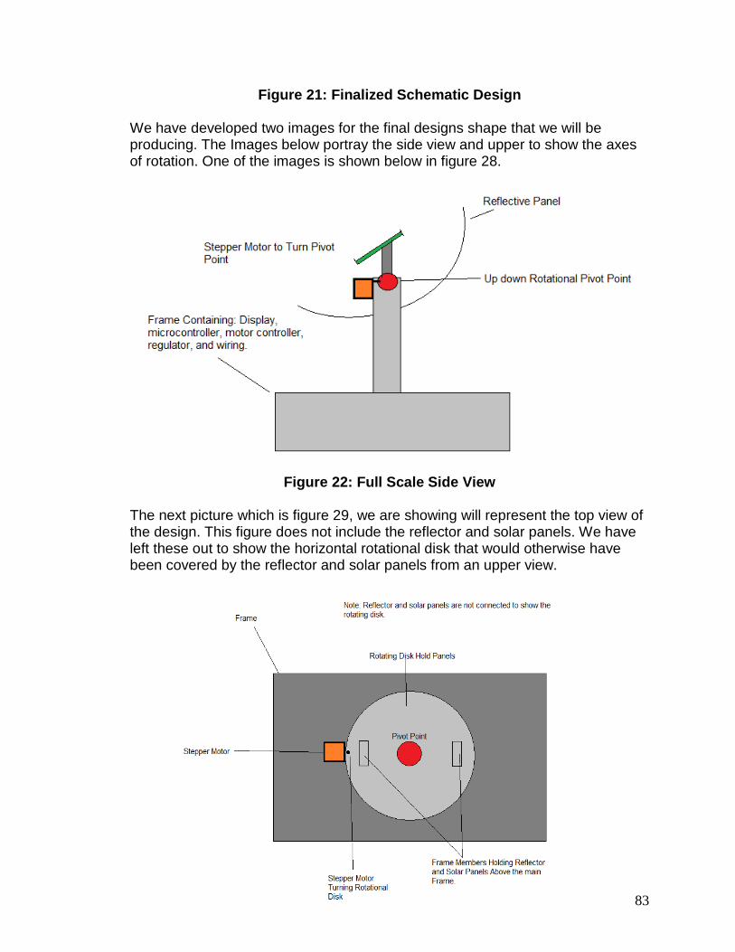
83
Figure 21: Finalized Schematic Design We have developed two images for the final designs shape that we will be producing. The Images below portray the side view and upper to show the axes of rotation. One of the images is shown below in figure 28.
Figure 22: Full Scale Side View
The next picture which is figure 29, we are showing will represent the top view of the design. This figure does not include the reflector and solar panels. We have left these out to show the horizontal rotational disk that would otherwise have been covered by the reflector and solar panels from an upper view.

84
Figure 23: Full Scale Top View
5.0 Vendors and Budget The most important thing we must consider when dealing with the purchases of items from a company is where they are located and how long it will take for the item to arrive. These aspects are very important due to the fact that we don’t want to have to wait too long to start building especially dealing with the amount of presentations for our classes. These presentations will determine how fast we must start on the building of the project The vendors available to determine our product selection will be from many company backgrounds. One of these companies is Microchip Direct. This website company specializes in selling different types of electronic devices such as microcontrollers, displays, as well as microchips and even Radio frequency devices. This company has been around for a long time selling their product in volume amounts depending on how small or big their product is. This company also has the latest in datasheet references which is what our group has used to become more familiar with certain products. Another vendor that we have considered buying items from is most likely from eBay or even 411 Technology Systems. First off, eBay is a company that has been around for the last decade selling products through bids and auctions from people in general. They are a company that is mostly worldwide as well letting even people in different language boundaries sell product also. 411 Technology Systems is another company specializing in selling displays, card readers and even robotics supplies. They are a company that deals with mostly hardware materials in their selling methods. Sparkfun Electronics is also another type of vendor that has deals with selling electronic devices for years. Mostly selling microcontrollers, as well as I/O boards and even displays and other devices, this store has very good talking information about their products and even their shipping methods. Radio Shack is also another vendor that specializes in appliances from phones to audio systems. Through these vendors we will be most likely getting resistors, capacitors, as well as even voltage regulators for the project. Table 8 and 9 shows information on the pricing specs for our project. Name Producer Operating
Voltage Description Price
Sabertooth Dual 5A Motor Driver
Trossen Robotics
6V-18V 5A Continuous
Operates 2 motors Runs on NiMH/NiCd Batteries
$59.99

85
EasyDriver vA Trossen Robotics
7V-30V 150-750mA/phase
Operates 1 Unipolar motor
$14.95
L298 Trossen Robotics
5V-46V 2A
Operates 1 Dual phase motor
$23.50
LMD18200 HVWTech Up to 55V 3A
Operates 1 Stepper Motor
$13.95
Table 8: Motor Controller Pricing
DC Motors Motor Name
Producer Operating Voltage
Stall Torque Rotational Speed
Description Price
M4-R0062-12
First CIM 6v-12v 343.27 oz-in 2424mN-m
No Load RPM 5310
65% efficient No Internal Gears
$28.00
IG-32RGM IG 12V 10.2N-m Rpm 220
1:27 Geared Reduction Ratio
$34.40
Stepper Motors Motor Name
Producer Operating Voltage
Stall Torque
Rotational Speed
Description Price
ROB-9238
Sparkfun 12V 2.3kg*cm RPM-n/a
Step Angle 1.8 degrees 2 Phase
14.95
STP-MTR-17040
Automation Direct
12V 61 oz-in RPM-n/a Step Angle 1.8 degrees 200 steps/revolution
$17.00
Table 9: Motor Pricing
5.1 Price Listing At the end of the Senior Design 2 semester we have compiled a list of parts and prices. We are also trying to keep the cost of many components to a minimum in

86
the event that we break an expensive component. This is so we will have enough funds left over from the sponsorship to cover the damaged components. The one component that is not completely finalized are the solar panels. We are saving these for last so that when we are sure that most of the design is completed, specific parts are purchased or on their way, we will have a more exact amount we can spend on panels. This is due to that fact that we do not know if we will break anything and do not want to spend all the money at once so if and when something breaks we will not be paying out of pocket. It is also entirely possible that parts will be dropped according to unforeseen difficultly in reproducing the design, in which case the budget will be changed. More than likely though if we do drop design aspects we will at that moment be decided on if we should purchase higher quality panels. We will focus the excess money towards the panels because the more efficient the panels are the better our project will produce its desired charging potential. For the actual purchases, the panels were purchased from wholesalesolar.com. Most of the parts were purchased offline from various robotics websites which include trossenrobotics.com and sparkfun.com, at these sites we have found reasonable pricing compared to other venders. The frame materials, regulators and the circuit components such as resistors and capacitors were purchased locally. The local stores purchased from will be Lowes and Radio Shack as documented in Table 10. Part Company Purchases Arduino Mega 2560 Microcontroller
MakerSHED (online) $73.20
6” 110lb Linear Actuator
Trossen Robotics (online)
$143.14
2 UPG 10 watt Solar Panels
Wholesale Solar (online)
$99.85
Solar Panel & Circuitry Wire, male pins
SkyCraft $5.00
Hitachi HD 44780 LCD Display
Gravitek U.S. (online) $23.55
Frame Materials Home Depot $18.23 Frame Materials Lowes $5.31 Frame Materials Home Depot $7.41 Breadboard / Circuit Materials
SkyCraft $26.09
Batteries SkyCraft $35.73 PhotoResistors Adafruit (online) $12.65 Circuit Materials Radio Shack $6.39 Circuit Supplies Radio shack $8.07

87
Frame & Frame Materials (metal, bolts, wood, etc…)
Lowes, Paradise Hobbies Inc
$154.05
L298 Dual H Bridge Motor Driver, EasyDriver V4 Stepper Motor Driver
Trossen Robotics (online)
$56.65
2 EasyDriver V4 Stepper Motor Driver, 2 BiPolar Stepper Motors
Trossen Robotics (online)
$72.03
Solar Panel & Circuitry Wire, male pins
SkyCraft $1.66
Total $749.01
Table 10: Component Pricing and Suppliers
6.0 Summary and Conclusion
6.1 Project Summary In our project display we have summarized the main details of how the project will work and the focus of the project as well as in what manner we will conduct the project. Through the main research of the details of the project, we were better able to understand the features and capabilities that this project will need to have when we start building the design. These features we have talked about include the use of the microcontrollers in the circuit as well as what types of microcontrollers we will be using towards our final design output. The main goal of the next semester will be for us to figure out the certain values for the resistances as well as the capacitance values for our connected circuit and also whether or not some of the items we have discussed in this paper will still be used or not since most ideas change over a time period until the end result is reached. Through more guided research we also understood more about our responsibilities and roles for the project. The goals and specifications that we set out for this project must be accomplished; these goals as we stated must be:
• Accomplishing the set prototype design • Maintaining the right stability of the project as well as keeping the
components in line with our set milestones • Keeping our goal of charging our designated supplies (Batteries)

88
• Avoiding the worst case scenario of Murphy’s Law by making sure the project works at all times and not at a specific time boundary
• Testing our final result as well as the calculations for error changes The more we can avoid errors within the time period, the more we can improve our design. As stated within the budget as well, we have changed many things. This will have to be a consideration throughout this next semester for our funding abilities also due to the fact that we have looked more and more at recent projects and have seen that depending on how much money is put forth towards the effort of this project will have a dramatic change to the project in general as well. In spite of this, there is a chance that even with a lack of funding we could have the ability to produce a well working design as well, so that means that our building approaches will be determined in our knowledge of the facts and the conglomeration of all the research that we have gathered over these past months. More of the project design approach was explained in detail within the Design Summary and Conclusion portion of the paper. The amount of meetings that will be conducted in the spring will be an integral portion of our finalization of the project as well. The meetings we have had for the project whether it was to design the initial documentation, the Table of Contents, and even show the rough draft of the paper with its specifications will prove useful as well due to the fact that these separate elements have helped the paper to become more informational. The roles and responsibilities that we each have been assigned will be to our benefit as well in the fact that we must work together as a team as well as work alone to discover our true potential on figuring out our portions. We have each set ourselves up for a position that we find interesting to each of us as stated in the flowchart described in the Roles and Responsibilities section of the report. These sets of roles can also change as we get farther into the project because we may find something that interests us more than we thought before in the past or our approach may even change throughout these next coming months. We won’t be able to perfectly feel compatible with our design until we make it through our mistakes and finally reach a conclusion to where we are heading in our approach. Another set of considerations that were displayed in the project were the important milestones that lead to the functioning of the project as well as the different research projects that were comparisons to our project. These other research projects were important in seeing what other schools and groups have accomplished in the past years and seeing how our project can be worked to a better solution based on the problems that the other groups have had. The testing procedure was another important portion of the paper as well in the fact that it set the guidelines for how we are going to test our components and why they will be tested.

89
The budget estimation is another important consideration but this estimation could possibly change depending on how much funding it will take to build this finalized design. Once this design is looked into more, then we will finally be able to decide on what we can or cannot get for our materials. This is the reason why there are going to be alternate components along with our paper to show what it is that we can get in addition to the parts already desired for the project. In addition to this paper, we discussed the design for our project using the designated software to replicate what our final result should look like. Through the explanation of the design for this project we can give insight to the consumer in letting them know where we stand as of today with our features, applied features, and even the importance of the separate parts of the project contributing to the project as a whole.
6.2 Project Conclusion In conclusion, we have learned more about how to distinguish the facts and citing sources of a company or even another paper through the use of ethics and principles. What is very important is the fact that we need to focus on how these materials work and thanks to the datasheets and website information we could realize some of the right materials to aim for in our choosing of supplies. The hardest part will be building the materials as well as soldering them in the right way as to not ruin the components. This could end up taking up a lot more time when it comes to production. In January, we will be gathering our final results and finalizing what materials we need to buy for our building of the machine. Throughout Senior Design II, we finalized our findings with Progress Energy for the Annual Symposium. What we did to get our paper finalized for now included the following procedure for this project. This is an important procedure when considering any type of project:
• Picked out a problem • Started research on the problem • Looked into how this project will be designed • Picked out the vendors for the components for the project • Gathered our results together as a group through meetings and class time • Conglomerated and revised different considerations within the paper as a
whole so that we could successfully construct the project. The research and formulas from different sources has helped us to use all the knowledge from all of our previous courses like Linear Controls, Embedded Systems, or even Electronics. These classes were the fundamental backgrounds for helping us to reach our goal of picking this project design. As was stated before, the reason for choosing this product was not to just design it for a limited

90
time use but to design it for consumers to use in future developments. Pretty much during the after semester portion of this first course in Senior Design will involve more research methods into seeing where more of our problems lie as well as becoming more knowledgeable with the information stated in datasheets. As well as learning about the ethics using other sources correctly, we also have learned more about the financial responsibility of carefully choosing the right type of component so that we don’t buy something too expensive but we also don’t buy the wrong product as well. Many types features deal with this project which is the reason why this is a worthy type of project to use as our design. Some of these types of features deal with how this project deals with the uses of renewable energy which is going to be an important type of energy source in the near future. What we mean to say is that doing a project whether it deals with solar power, wind power, or even water power is a good experiential approach towards finding out if these types of energy could possibly help us out to reach a goal of not having to depend o other places for energy sources but to create our own sources. Using these sources will also be a new innovation in the field of technology as well seeing that most other companies are producing certain items such as solar powered cars, wind turbines, solar cell houses as well as even solar powered heating devices. As we can see, this field is rapidly growing and will continue to in the nearby future despite our continued usage of fossil fuels since there is no guarantee that we will be able to fully get away from using this type of power. If we can deviate from this type of power, then we will be able to finally help out the world by using less emissions leading to not hurting the ozone. There are certain features that must be accomplished in the future in order to get us away from these types of fossil fuels, if we can follow these guidelines then we may stand a chance at fully experiencing alternative renewable energy:
• Looking into more methods of power • Depending less on other countries that are willing to heighten prices on
fuel all the time • Figure out how the alternative method will be able to fully provide power to
the places desired • Keeping away from monopolies that keep their own rules on power • Designing more types of inventions suited to not only help out the
environment but also to help consumers out as well What we may also realize while doing this project in the near future is that we may or may not end up finding something within our design that other people haven’t seen before. Something that most designers have developed in the decades of the past when it comes to creating inventions. Even though something of this nature has been built time and time again that doesn’t mean that a different type of way to create it will be a mundane approach. Many

91
companies have tried to do this approach like Apple, IBM, and even other companies that aren’t even heard of that much such as third party companies. Finally, through our completion of this project as well as our competing in the Progress Energy Symposium, we learned how to gain experience into the real world of designing applications and working under pressure such as deadline work that must be completed in a timely manner. This will also help us to create a professional appearance as we venture into the working world as well as depending on how we take our approach in our lives. As we gather more and more research into delving more into the design it will help us to focus more on what is needed for analysis into circuit design, and other application approaches in design. We used all the knowledge that we have learned over these four years as well as the knowledge that we are gaining through research and for future courses of study in order to complete the final S.E.G.S. design as seen here in figure 24, the tracking device itself along with it’s electronics case, tv, and Nintendo Wii.
Figure 24: Final S.E.G.S. Design

92
Appendix A: Bibliography [1] 20X4 White on Blue Character LCD with Backlight.
[2] Kruger, Anton.
Gravitech, 2006-2010. < http://store.gravitech.us/20chbllcd.html>
Photodiode Nomenclature.
[4]
ChipCenter QuestLink, 2003. < http://archive.chipcenter.com/eexpert/akruger/akruger039.html>
PIC18F87J90 Family Data Sheet.
[5]
Microchip Direct, 2010. < http://www.microchip.com/wwwproducts/Devices.aspx?dDocName=en541241>
PIC24F04KA201 Family Data Sheet.
[6]
Microchip Direct, 2010. < http://www.microchip.com/wwwproducts/Devices.aspx?dDocName=en542037>
Arduino Mega 2560.
[7] Anand, Naren.
Sparkfun Electronics, 2010. < http://www.sparkfun.com/products/9949>
Implementation.
[8]
Connexions. 19 Dec, 2007. < http://cnx.org/content/m15679/latest/>
LCD interfacing with Microcontrollers tutorial.
[9] “Technical Bulletin.”
Rickey’s World, World of Microcontrollers and Microprocessors, 2010. < www.8501projects.net/lcd-interfacing/introduction.php>
Cadmium Sulfide vs. Silicon.
<
Precision Multiple Controls, Inc., 2002.
http://www.precisionmulticontrols.com/PDFdownload/Sulfidevssilicon.pdf> [17] Solar Cell Investigations. djb MicroTech Ltd, 2010. < http://www.djb.co.uk/ppen_solar_investigations.html> [21] Secrets of Arduino PWM. Arduino, 2010. < http://arduino.cc/en/Tutorial/SecretsOfArduinoPWM > [23] GNOME Power Manager Manual. Richard Hughes, 2006. < http://www.gnome.gr/files/gnome226/GNOMEGRDELIVERABLE/gnome-power-manager/documentation_gnome-power-manager.html> [25] Connecting the Voltage Regulator to a battery and Solar and Panel. The Solar Centre Ltd., 2010 < http://www.thesolarcentre.co.uk/PDF/Connecting%20a%20Solar%20Panel%20Power%20System.pdf > [26] Battery Guide. Micheal Bluejay, 1999-2009. <http://michaelbluejay.com/batteries/>

93
Appendix B: Permission Permission to use Figure 2
Permission to use Figure 3
Dear Diijon,
Thank you for your interest in Connexions and the content our authors have written. Connexions is a supporter of open source educational material. You can use any content in Connexions without contacting the author for permission as long as you give attribution including: • Author names • Title of the work • Connexions URL where the work can be found When an author puts content into Connexions, he or she agrees to publishing that content under the Creative Commons Attribution License. That license allows you to use the content in most any way, as long as you attribute the work in the manner specified by the author or licensor. Also you must make clear to others the license terms of this work. Please see a brief version this license agreement at the following Web page: http://creativecommons.org/licenses/by/3.0/ A more detailed wording of the license is shown on the following Web page:

94
http://creativecommons.org/licenses/by/3.0/legalcode To see examples of different ways to cite the content, click the "Cite this content" link at the bottom of the content. This reply to your e-mail has been sent to you and to Narendra Anand , who is the author of the content you mentioned in your message.
Regards,
On Fri, Nov 12, 2010 at 12:22 AM, Diijon Gumbs
Katherine Fletcher
<[email protected]> Hello, me and my classmates are doing a Senior Design project and were wondering if you would be able to grant us permission to use the picture of the Spectral Response of the responsitivity of a photodiode as displayed on your website at
wrote:
http://cnx.org/content/m15679/latest/ under the Laser/Photodetector section. We will definitely reference your website in our paper. Thank you for your patience. Sincerely, Diijon Gumbs _______________________________________________ cnx mailing list [email protected] http://mailman.cnx.rice.edu/mailman/listinfo/cnx
-- Katherine Fletcher, Technical Director and Project Manager, Connexions, MS 375 (713) 348-3662 Web: http://cnx.org Email: [email protected], [email protected] Connexions Community: http://conference.cnx.org, http://blog.cnx.org , http://twitter.com/cnxorg,http://www.facebook.com/cnx.org, http://cnxconsortium.org/, http://devblog.cnx.org Permission to use Figures 4,5, and 6 Hello Martin Thank you for your interest in our website. There is no problem in using any of the Energy Graphs on our website or the ones attached. All I would ask is that you add an acknowledgement at the end

95
of your report which includes our web address. I have redone the graphs as the original screen shots were not to hand. I wish you well with your project. Kind regards Derek Walker for djb microtech ltd At 00:32 30/11/2010, you wrote:
email: [email protected] realname: kaniel school: university of central florida mesg: Hello djb, I'm currently an electrical engineering student working on a senior design project dealing with solar panels. I found your picture on your site here
http://www.djb.co.uk/ppen_solar_investigations.html
Derek Walker djb microtech ltd Tel: 01475 786540 email: [email protected]
depicting the load to power ratios for just the solar cell, the parallel arrangment, and the series arrangment. I was wondering if I could have your approval to use your pictures as graphs in my report to show how the loads and powers are related in different arrangments? Also if you are able to attach a production worthy copy of the pictures ( 300 dpi) that would be greatly appreciated! Thanks! -Kaniel ================================== REMOTE_HOST= REMOTE_ADDR=132.170.114.223 HTTP_USER_AGENT=Mozilla/5.0 (Windows; U; Windows NT 5.1; en-US) AppleWebKit/533.4 (KHTML, like Gecko) Chrome/5.0.375.55 Safari/533.4 REMOTE_USER=
www.djb.co.uk
Permission to use Figure 9

96
Permission to use Figure 11
Permission to use Figure 12

97