seismic analysis of a vertical water tank - · pdf fileimpulsive mode, and 0.5% damping was...
TRANSCRIPT

SISOM 2011 and Session of the Commission of Acoustics, Bucharest 25-26 May
SEISMIC ANALYSIS OF A VERTICAL WATER TANK
Nicolae ZEMTEV*
AMEC NUCLEAR RO e-mail: [email protected]
The calculation presented here was part of a benchmark exercise initiated by the International Atomic Energy Agency (IAEA). The purpose of the benchmark was to understand how several nuclear equipments and structures were affected during a strong earthquake and to calibrate simulation technologies examining their ability to represent the observed behavior and identifying main parameters influencing the response. The report details the approach used to predict the observed buckling modes of a vertical water tank, during a strong earthquake. The calculations include modal, spectral and time-history analysis using two finite element models. The water inside the tank was modeled using specific Ansys finite elements as described below. Thus, the numerical models succeeded in capturing not only the water mass, but also its behavior. The calculated results show the predicted tank behavior is similar to the real one, and the fluid-structure interaction was accurately modeled.
1. INTRODUCTION
The present report summarizes and discusses the results of the analyses performed by AMEC as part of a benchmark exercise. The intent was to predict the behavior of a vertical storage tank subjected to a strong earthquake.
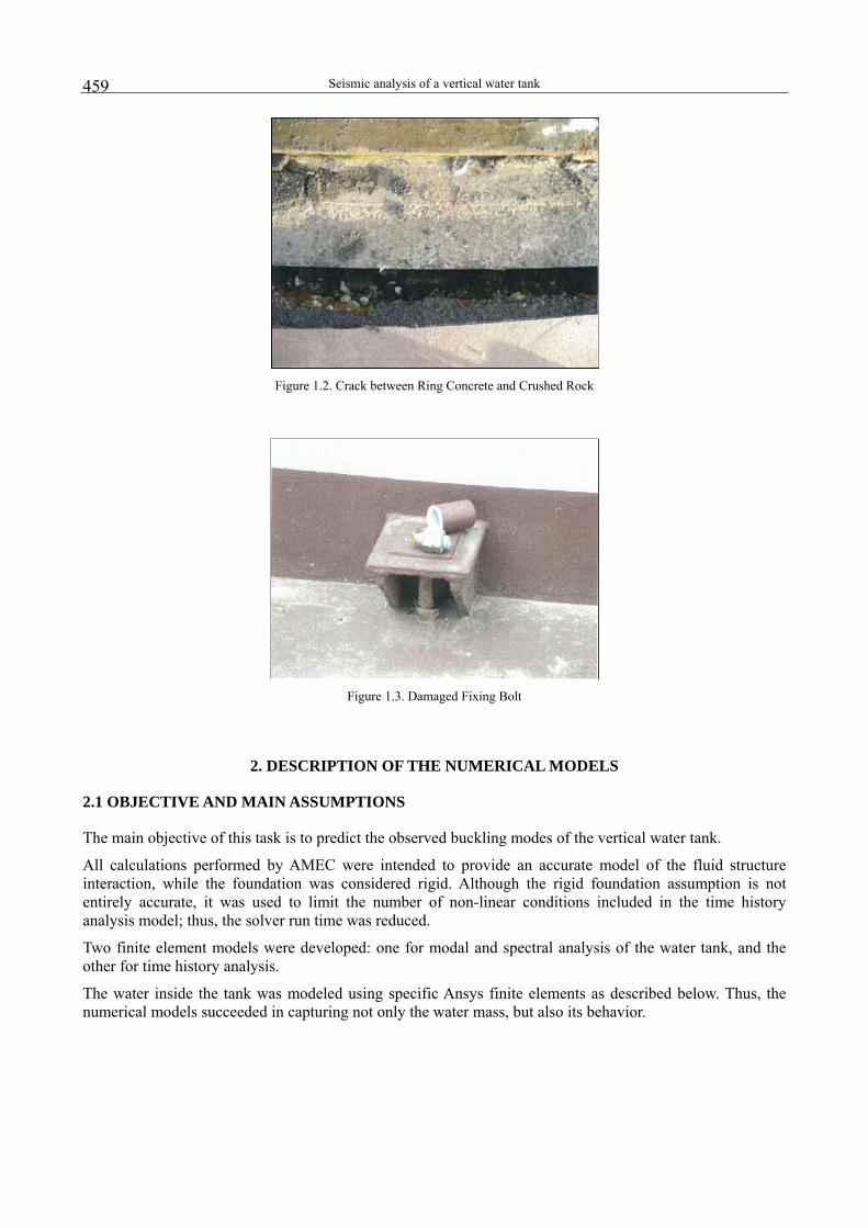
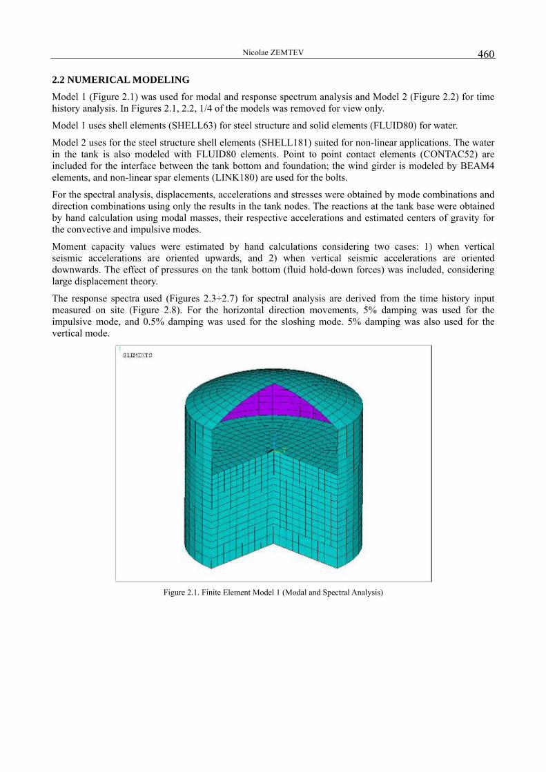
Figures 1.1÷1.3 below show the effects of the earthquake on the actual tank. These included:
- Diamond shape buckling at the upper shell level
- Elephant foot buckling near the tank base
- Damage to the foundation and fixing bolts due to severe uplift of the tank base
Figure 1.1. Diamond Shape Buckling
Seismic analysis of a vertical water tank
459
Figure 1.2. Crack between Ring Concrete and Crushed Rock
Figure 1.3. Damaged Fixing Bolt
2. DESCRIPTION OF THE NUMERICAL MODELS
2.1 OBJECTIVE AND MAIN ASSUMPTIONS
The main objective of this task is to predict the observed buckling modes of the vertical water tank.
All calculations performed by AMEC were intended to provide an accurate model of the fluid structure interaction, while the foundation was considered rigid. Although the rigid foundation assumption is not entirely accurate, it was used to limit the number of non-linear conditions included in the time history analysis model; thus, the solver run time was reduced.
Two finite element models were developed: one for modal and spectral analysis of the water tank, and the other for time history analysis.
The water inside the tank was modeled using specific Ansys finite elements as described below. Thus, the numerical models succeeded in capturing not only the water mass, but also its behavior.
Nicolae ZEMTEV
460
2.2 NUMERICAL MODELING
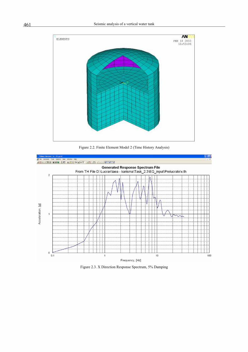
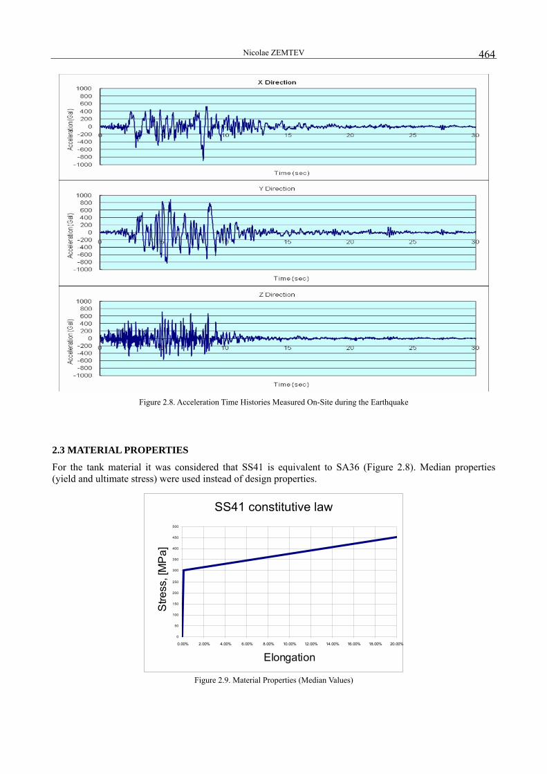
Model 1 (Figure 2.1) was used for modal and response spectrum analysis and Model 2 (Figure 2.2) for time history analysis. In Figures 2.1, 2.2, 1/4 of the models was removed for view only.
Model 1 uses shell elements (SHELL63) for steel structure and solid elements (FLUID80) for water.
Model 2 uses for the steel structure shell elements (SHELL181) suited for non-linear applications. The water in the tank is also modeled with FLUID80 elements. Point to point contact elements (CONTAC52) are included for the interface between the tank bottom and foundation; the wind girder is modeled by BEAM4 elements, and non-linear spar elements (LINK180) are used for the bolts.
For the spectral analysis, displacements, accelerations and stresses were obtained by mode combinations and direction combinations using only the results in the tank nodes. The reactions at the tank base were obtained by hand calculation using modal masses, their respective accelerations and estimated centers of gravity for the convective and impulsive modes.
Moment capacity values were estimated by hand calculations considering two cases: 1) when vertical seismic accelerations are oriented upwards, and 2) when vertical seismic accelerations are oriented downwards. The effect of pressures on the tank bottom (fluid hold-down forces) was included, considering large displacement theory.
The response spectra used (Figures 2.3÷2.7) for spectral analysis are derived from the time history input measured on site (Figure 2.8). For the horizontal direction movements, 5% damping was used for the impulsive mode, and 0.5% damping was used for the sloshing mode. 5% damping was also used for the vertical mode.
Figure 2.1. Finite Element Model 1 (Modal and Spectral Analysis)
Seismic analysis of a vertical water tank
461
Figure 2.2. Finite Element Model 2 (Time History Analysis)
Figure 2.3. X Direction Response Spectrum, 5% Damping

Nicolae ZEMTEV
462
Figure 2.4. X Direction Response Spectrum, 0.5% Damping
Figure 2.5. Y Direction Response Spectrum, 5% Damping

Seismic analysis of a vertical water tank
463
Figure 2.6. Y Direction Response Spectrum, 0.5% Damping
Figure 2.7. Vertical Direction Response Spectrum, 5% Damping
Nicolae ZEMTEV
464
Figure 2.8. Acceleration Time Histories Measured On-Site during the Earthquake
2.3 MATERIAL PROPERTIES
For the tank material it was considered that SS41 is equivalent to SA36 (Figure 2.8). Median properties (yield and ultimate stress) were used instead of design properties.
SS41 constitutive law
0
50
100
150
200
250
300
350
400
450
500
0.00% 2.00% 4.00% 6.00% 8.00% 10.00% 12.00% 14.00% 16.00% 18.00% 20.00%
Elongation
Stre
ss, [
MP
a]
Figure 2.9. Material Properties (Median Values)
Seismic analysis of a vertical water tank
465
2.4 BOUNDARY CONDITIONS
Fluid and shell coincident nodes at fluid / tank boundary are coupled in the directions normal to the interfaces. Thus, lateral displacements of the fluid relative to the tank wall and bottom are permitted.
For modal analysis (Model 1), the SHELL63 nodes at the bottom of the tank were restrained in all directions (displacements + rotations).
Model 2 has a rigid foundation with its nodes restrained in all directions. Contact elements between the tank bottom and the foundation allow for the development of friction forces (friction coefficient 0.8).
3. MAIN RESULTS OF PERFORMED ANALYSES
3.1 MODAL ANALYSIS
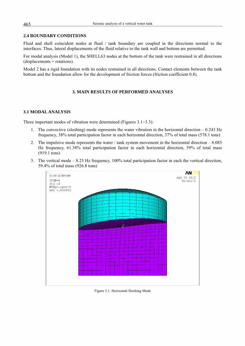
Three important modes of vibration were determined (Figures 3.1÷3.3):
1. The convective (sloshing) mode represents the water vibration in the horizontal direction – 0.243 Hz frequency, 38% total participation factor in each horizontal direction, 37% of total mass (578.1 tons)
2. The impulsive mode represents the water / tank system movement in the horizontal direction – 8.085 Hz frequency, 61.38% total participation factor in each horizontal direction, 59% of total mass (919.1 tons)
3. The vertical mode – 8.25 Hz frequency, 100% total participation factor in each the vertical direction, 59.4% of total mass (926.8 tons)
Figure 3.1. Horizontal Sloshing Mode

Nicolae ZEMTEV
466
Figure 3.2. Horizontal Impulsive Mode
Figure 3.3. Fundamental Vertical Mode
3.2 RESPONSE SPECTRUM ANALYSIS
The total overturning moment at tank base (X and Y directions combined) was obtained 71.6MNm.
Seismic analysis of a vertical water tank
467
For comparison, moment capacity values were estimated by hand calculations using the approach in [1], considering two cases: 1) when vertical seismic accelerations are oriented upwards, and 2) when vertical seismic accelerations are oriented downwards. This included the calculation of fluid hold-down forces on the tank bottom from the pressure distribution resulted from the finite element model. Note that the following assumptions were made:
- The maximum uplift of the tank base was 90 mm, which is the maximum elongation of bolt before break point; this accounts for the evulsion of fixing bolt no. 8.
- The failure mode at the tank base was considered elephant-foot buckling
Table 3.1 below gives a comparison between the total overturning moment at tank base and the moment capacity calculated according to [1]. It is interesting to note that the overturning moment at the tank base due to seismic movement is 1.87 and, respectively, 1.47 greater than the two computed moment capacities. These values are consistent with usual values of inelastic energy absorption factors calculated for these structures and suggests that part of the energy was dissipated through plastic deformations (confirms that the failure mode at the tank base was elephant-foot buckling). Table 3.1. Comparison of Demand and Capacity (Overturning Moment)
Case Overturning moment, MR
[MNm]
Moment capacity, MC [MNm] MR / MC
Vertical accelerations upwards 71.6 38.3 1.87 Vertical accelerations downwards 71.6 48.8 1.47
3.3 TIME HISTORY ANALYSIS
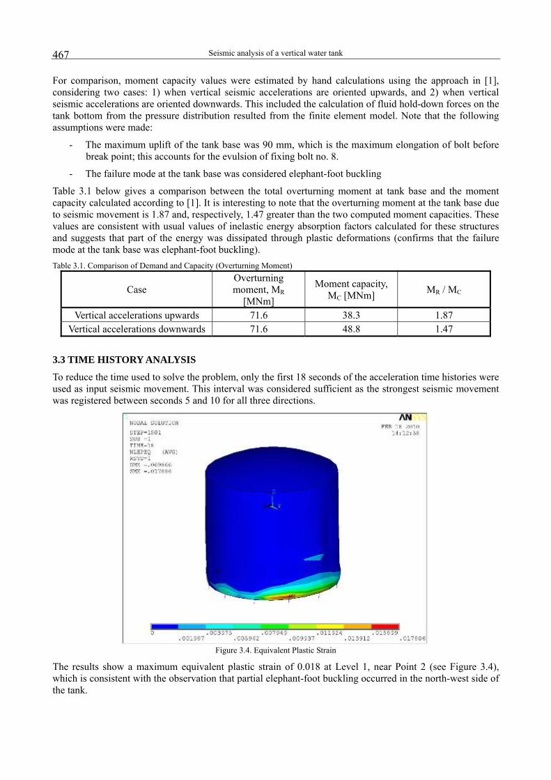
To reduce the time used to solve the problem, only the first 18 seconds of the acceleration time histories were used as input seismic movement. This interval was considered sufficient as the strongest seismic movement was registered between seconds 5 and 10 for all three directions.
Figure 3.4. Equivalent Plastic Strain
The results show a maximum equivalent plastic strain of 0.018 at Level 1, near Point 2 (see Figure 3.4), which is consistent with the observation that partial elephant-foot buckling occurred in the north-west side of the tank.
Nicolae ZEMTEV
468
At upper levels the results show large maximum horizontal displacements (between 110 mm and 160 mm) as compared to lower levels (up to 30÷92 mm at level 4). This in turn demonstrates large elastic deformations at levels 6, 7, which may suggest diamond type buckling occurred all around the tank, as observed in the field.
Other useful results are:
- Vertical stresses in the shell near the tank base are greater than 140 MPa
- Vertical stresses in the shell at upper levels are, with a few exceptions, greater than 25 MPa
3.4 BUCKLING ESTIMATION
The "elephant-foot" buckling axial stress capacity, σbe, of the tank shell can be estimated by:
( )⎥⎦
⎤⎢⎣
⎡+
+⎥⎦
⎤⎢⎣
⎡+
−⎥⎥
⎦
⎤
⎢⎢
⎣
⎡
⎟⎟⎠
⎞⎜⎜⎝
⎛
⋅⋅
−=1
248/12.1
1111
15.1
1
2
SMPaS
StRp ye
sbyeCLbe
σσ
σσ
(1)
where
( )sb
tCL t/R
E605.0=σ
(2)
in which S1 = R/(400tsb), tsb is the tank wall thickness, R is the tank radius, p is the tank internal pressure, and σye is the effective yield stress of the tank material.
The diamond buckling capacity of the cylindrical shell, σbd, under combined axial bending and internal pressure can be essentially lower bound estimated from:
CLbd αησσ = (3)
where σCL is the "classical" shell buckling capacity (equation (2)), α is a capacity reduction factor due to imperfection and η is a plasticity reduction factor.
NASA SP-8007 document [4] defines different values for α depending upon whether the overall loading on the cylindrical shell is uniform axial compression or bending, and also incorporates an influence for internal pressure. From NASA SP-8007:
605.0γ∆γαNASA +=
(4)
(5) )e1(901.01γ Φaxial
−−⋅−=
(6) )e1(731.01γ Φbend
−−⋅−=
sbtR
161
=Φ (7)
where Δγ is an increase factor for internal pressure. We used the following equation to estimate Δγ:
for s1 ≤ 1.0: 015.0s935.0s624.1s076.1s181.0 121
31
41 +⋅+⋅−⋅+⋅−=γΔ
for s1 > 1.0: (8) 22.0γ∆ =
where
Seismic analysis of a vertical water tank
469
2
sbt1 t
REps ⎟⎟
⎠
⎞⎜⎜⎝
⎛⋅=
(9)
The value of η can be computed with 1η = if Δ ≤ 0.55
18.045.0+
Δ=η
if 0.55 < Δ ≤ 1.6 (10)
where:
(11) yCL /σασ=Δ
From equations (1) through (11) above, it can be seen that the elephant-foot buckling capacity decreases with the increase of pressure, and the diamond buckling capacity increases with the increase of pressure. Therefore, it can be concluded that at locations near the tank base, where the pressure has maximum values, the tank wall is more susceptible to elephant-foot buckling, while at the upper levels, where there is less or no internal pressure, diamond type buckling should occur. This conclusion is also consistent with observations made on site.
For example, near the tank bottom, where maximum pressures vary between 0.14 MPa and 0.24 MPa, the elephant-foot buckling stress ranges from 32 MPa to 85 MPa, while above water, where there is virtually zero pressure, the diamond buckling stress has a lower value: 24.5 MPa (diamond buckling occurs first).
The vertical stresses in the tank shell given in Section 3.3 above have values greater than the buckling capacities computed here. Therefore, the results show that elephant-foot buckling occurs near the tank base throughout the circumference of the tank wall, while diamond buckling occurs above water levels.
These results are close to what was observed on site.
4. DISCUSSIONS
The following conclusions can be formulated from the above results:
- The values of the vertical (compressive) stresses near the tank bottom, are all greater than the "elephant-foot" buckling axial stress capacities given in Section 3.4. This would suggest that this type of buckling occurs all around the tank, near its base.
- The maximum equivalent plastic strain is 0.018 near the tank base (see Figure 3.4), which is consistent with the observation that partial elephant-foot buckling occurred in north-west side of the tank.
- The values of the vertical (compressive) stresses above the water level are all greater or close to the value for diamond buckling given in Section 3. 4. This would suggest that this type of buckling occurs all around the tank, which is consistent with observations on site
- Also, at the upper levels, the results of the time history analysis model show large maximum horizontal displacements (between 110 mm and 160 mm) as compared to lower levels (up to 30÷92 mm at mid height). This in turn demonstrates large elastic deformations above the water level, which may suggest that diamond type buckling occurred all around the tank, as observed in the field.
The main difficulty of the time history analysis was to develop a realistic finite element model that does not require a long solving time. The problem was only partly resolved, by limiting the number of elements in exchange for some of the results accuracy.

Nicolae ZEMTEV
470
Another aspect that needs to be considered is the flexibility of the foundation, which may influence the results and should be accurately modeled.
REFERENCES
1. EPRI , Methodology for Developing Seismic Fragilities, EPRI TR-103959 Research Project, R. P. Kennedy, J. W. Reed, 1994. 2. AMEC Nuclear RO, ThSpec Version 1.6 / 2007. 3. Ansys Inc , Ansys Structural Analysis Guide, Ansys Release 11.0, 2007. 4. NASA , Buckling of Thin Walled Circular Cilinders, NASA SP-8007, 1965. 5. AMEC NUCLEAR RO, Integrated Management Manual man01-99.qa, Ed.1, Rev 2, April, 2011, Engineering Integrated
Management System Manual Developed to be in Compliance with the Requirements of: IAEA Safety Series no. GS-R-3 & GS-R-3.1(2006), CNCAN-NMC-02, 04, 05, 12(2003), CAN 3-N286-2/2000,10CFR50 Appendix B, 10 CFR 830.120 Quality Assurance, ASME-NCA-4000/1998, SR EN ISO 9001 (2008) and SR EN ISO 14001 (2005.)