seismic design criteria for new moment-resisting steel ... · pdf fileiii seismic design...
TRANSCRIPT

i
Pro
gram
to
Red
uce
the
Ear
thqu
ake
Haz
ards
of
Ste
el M
omen
t F
ram
e St
ruct
ures
FEDERAL EMERGENCY MANAGEMENT AGENCY FEMA XXX/January, 1999
Seismic Design Criteriafor New Moment-ResistingSteel Frame Construction
50%
DRAFT

i
Working Draft
This document has been produced as a preliminary working draft as part of theSAC Joint Venture’s project to develop practice guidelines for design, evaluation,repair, and retrofit of moment-resisting steel frame structures. The purpose ofthis draft is to permit the project development team and prospective users of theguidelines to explore the basic data requirements and alternative methods ofpresenting this data in an eventual series of guideline documents. Althoughportions of the document must necessarily appear in the form of an actualguideline, it is not intended to serve as an interim guideline document.Information contained in this document is incomplete and in some cases, isknown to be erroneous or otherwise incorrect. Information presented hereinshould not be used as the basis for engineering projects and decisions, norshould it be disseminated or attributed.

ii

iii
Seismic Design Criteria for NewMoment Resisting Steel Frame Construction
Report No. SAC-XX-XX-XX
SAC Joint Venturea partnership of:
Structural Engineers Association of California (SEAOC)Applied Technology Council (ATC)
California Universities for Research in Earthquake Engineering (CUREe)
Prepared for SAC Joint Venture Partnership byGuidelines Development Committee
Ronald O. Hamburger, Chair
John D. HooperRobert Shaw
Lawrence D. Reaveley
Thomas SabolC. Mark Saunders
Raymond H. R.. Tide
Project Oversight Committee
William J. Hall, Chair
John N. BarsomShirin AderRoger Ferch
Theodore V. GalambosJohn Gross
James R. HarrisRichard Holguin
Nestor IwankiwRoy G. Johnston
S. C. LiuDuane K. Miller
John TheissCharles ThorntonJohn H. Wiggins
SAC Project Management Committee
SEAOC: William T. HolmesATC: Christoper RojahnCUREe: Robin Shepherd
Program Manager: Stephen A. MahinProject Director for Topical Investigations: James O. MalleyProject Director for Product Development: Ronald O. Hamburger
SAC Joint Venture555 University Avenue, Suite 126
Sacramento, California 95825916-427-3647January, 1999

ii
THE SAC JOINT VENTURE
SAC is a joint venture of the Structural Engineers Association of California (SEAOC), theApplied Technology Council (ATC), and California Universities for Research in EarthquakeEngineering (CUREe), formed specifically to address both immediate and long-term needs relatedto solving performance problems with welded steel moment frame connections discoveredfollowing the 1994 Northridge earthquake. SEAOC is a professional organization composed ofmore than 3,000 practicing structural engineers in California. The volunteer efforts of SEAOC’smembers on various technical committees have been instrumental in the development of theearthquake design provisions contained in the Uniform Building Code as well as the NationalEarthquake Hazards Reduction Program (NEHRP) Provisions for Seismic Regulations for NewBuildings and other Structures (NEHRP Provisions). The Applied Technology Council is a non-profit organization founded specifically to perform problem-focused research related to structuralengineering and to bridge the gap between civil engineering research and engineering practice. Ithas developed a number of publications of national significance including ATC 3-06, which servesas the basis for the NEHRP Provisions. CUREe is a nonprofit organization formed to promote andconduct research and educational activities related to earthquake hazard mitigation. CUREe’s eightinstitutional members are: the California Institute of Technology, Stanford University, theUniversity of California at Berkeley, the University of California at Davis, the University ofCalifornia at Irvine, the University of California at Los Angeles, the University of California at SanDiego, and the University of Southern California. This collection of university earthquake researchlaboratory, library, computer and faculty resources is among the most extensive in the UnitedStates. The SAC Joint Venture allows these three organizations to combine their extensive andunique resources, augmented by subcontractor universities and organizations from around thenation, into an integrated team of practitioners and researchers, uniquely qualified to solveproblems related to the seismic performance of steel moment frame structures.
DISCLAIMER
The purpose of this document is to provide practicing engineers and building officials with aresource document for the design of moment-resisting steel frame structures to resist the effects ofearthquakes. The recommendations were developed by practicing engineers based on professionaljudgment and experience and a program of laboratory, field and analytical research. No warrantyis offered with regard to the recommendations contained herein, either by the FederalEmergency Management Agency, the SAC Joint Venture, the individual joint venturepartners, their directors, members or employees. These organizations and their employees donot assume any legal liability or responsibility for the accuracy, completeness, or usefulness ofany of the information, products or processes included in this publication. The reader iscautioned to carefully review the material presented herein and exercise independentjudgment as to its suitability for application to specific engineering projects. These guidelineshave been prepared by the SAC Joint Venture with funding provided by the Federal EmergencyManagement Agency, under contract number EMW-95-C-4770.

iii
TABLE OF CONTENTS1. Introduction
1.1. Purpose1.2. Intent1.3. Background1.4. Application1.5. The SAC Joint Venture1.6. Sponsors1.7. Guidelines and Overview
2. General Requirements2.1. Scope2.2. Applicable Codes and Standards2.3. Design Performance Objectives2.4. System Selection
2.4.1. Configuration and Load Path2.4.2. Selection of Moment Frame Type2.4.3. Connection Type2.4.4. Redundancy
2.5. Structural Materials2.5.1. Material Specifications2.5.2. Material Strength Properties
2.6. Structural Analysis2.7. Mathematical Modeling
2.7.1. Basic Assumptions2.7.2. Frame Configuration2.7.3. Horizontal Torsion2.7.4. Foundation Modeling2.7.5. Diaphragms2.7.6. P-Delta Effects
2.7.6.1. Static P-∆ Effects2.7.6.2. Dynamic P-∆ Effects
2.7.7. Multi-direction Excitation Effects2.7.8. Verification of Analysis Assumptions
2.8. Frame Design2.8.1. Strength of Beams and Columns2.8.2. Panel zone Strength2.8.3. Connection Strength and Degradation2.8.4. P-Delta Effects2.8.5. Section Compactness Requirements
2.9. Connection Design2.10. Specifications2.11. Quality Assurance and Control2.12. Other Structural Systems
2.12.1. Column Splices

iv
2.12.2. Column Bases
3. Connection Qualification3.1. Scope3.2. Basic Design Approach
3.2.1. Frame Configuration3.2.2. Inter-Story Drift Capacity3.2.3. Connection Configuration3.2.4. Determine Plastic Hinge Locations3.2.5. Determine Probable Plastic Moment at Hinges3.2.6. Determine Shear at the Plastic Hinge3.2.7. Determine Strength Demands at Each Critical Section
3.3. General Requirements3.3.1. Beams
3.3.1.1. Beam Flange Stability3.3.1.2. Beam Depth Effects3.3.1.3. Beam Flange Thickness Effects
3.3.2. Welded Joints3.3.2.1. Through-Thickness Strength3.3.2.2. Base Material Notch-Toughness3.3.2.3. Weld Wire Notch-Toughness3.3.2.4. Weld Wire Matching and Overmatching3.3.2.5. Weld Backing, Runoff Tabs, Reinforcing Fillet Welds3.3.2.6. Overlay Fillet Welds3.3.2.7. Weld-Access Hole: Size, Shape, Workmanship
3.3.3. Other Design Issues for Welded Connections3.3.3.1. Continuity Plates3.3.3.2. Panel Zone Strength
3.3.4. Bolted Joints3.3.4.1. Existing Conditions3.3.4.2. Connection Upgrades
3.4. Pre-qualified Welded FR Connections3.4.1. Welded Unreinforced Flange
3.4.1.1. Procedure for Sizing Shear Tabs3.4.1.2. Procedure for Weld Sizing
3.4.2. Welded Cover Plated Flanges (WCPF)3.4.3. Welded Flange Plates (WFP)3.4.4. Reduced Beam Section (RBS, or Dog Bone)
3.4.4.1. Procedure for Sizing Section Reduction3.4.4.2. Procedure for Sizing Shear Tabs3.4.4.3. Procedure for Flange Weld Sizing3.4.4.4. Fabrication Requirements3.4.4.5. Supplemental Lateral Bracing at RBS
3.4.5. Welded Single Haunch (WSH)3.4.6. Welded Double Haunch (WDH)3.4.7. Side Plate (SP)

v
3.4.8. Slotted Web (SW)3.5. Pre-qualified Bolted FR Connections
3.5.1. Bolted End Plate3.5.2. Welded Flange Plates with Bolted Beam (WFPBB)
3.5.2.1. General Design Procedure3.5.2.2. Bolt Shear3.5.2.3. Flange Plate3.5.2.4. Beam Flange3.5.2.5. Groove Weld3.5.2.6. Panel Zone
3.5.3. Bolted Bracket (BB)3.6. Pre-qualified PR Connections
3.6.1. Double Split Tee Connections (DST)3.6.1.1. Procedure for Sizing Tees3.6.1.2. Procedure for Sizing Bolts to Column Flange3.6.1.3. Procedure for Sizing Bolts to Beam Flange
3.6.2. Single Tee Composite (STC) Connection3.6.2.1. Procedure for Sizing Tees3.6.2.2. Procedure for Sizing Bolts to Column Flange3.6.2.3. Procedure for Sizing Bolts to Beam Flange3.6.2.4. Procedure for Sizing Shear Studs3.6.2.5. Procedure for Sizing Slab Reinforcement
3.6.3. Single Angle Composite (SAC)3.6.4. Shear Tab Composite (STC)
3.7. Non-pre-qualified Connections3.7.1. Testing Procedure3.7.2. Analytical Prediction of Behavior3.7.3. Determination of Resistance Factor
4. Performance Evaluation4.1. Scope4.2. Performance Definition
4.2.1. Hazard Specification4.2.1.1. General4.2.1.2. Ground Shaking4.2.1.3. Other Hazards
4.2.2. Performance Levels4.2.2.1. Structural Performance Levels
4.2.2.1.1. Incipient Damage Performance Level (S-1)4.2.2.1.2. Collapse Prevent Performance Level (S-5)
4.2.2.2. Nonstructural Performance Levels4.2.2.2.1. Operational Performance Level (N-A)4.2.2.2.2. Immediate Occupancy Level (N-B)4.2.2.2.3. Life Safety Level (N-C)4.2.2.2.4. Hazards Reduced Level (N-D)
4.3. Evaluation Approach

vi
4.4. Analysis4.4.1. Alternative Procedures4.4.2. Procedure Selection4.4.3. Linear Static Procedure (LSP)
4.4.3.1. Basis of the Procedure4.4.3.2. Modeling and Analysis Considerations4.4.3.3. Determination of Actions and Deformations
4.4.3.3.1. Pseudo Lateral Load4.4.3.3.2. Vertical Distribution of Seismic Forces4.4.3.3.3. Horizontal Distribution of Seismic Forces4.4.3.3.4. Floor Diaphragms4.4.3.3.5. Determination of Deformations4.4.3.3.6. Determination of Column Demands
4.4.4. Linear Dynamic Procedure (LDP)4.4.4.1. Basis of the Procedure4.4.4.2. Modeling and Analysis Considerations
4.4.4.2.1. General4.4.4.2.2. Ground Motion Characterization4.4.4.2.3. Response Spectrum Method4.4.4.2.4. Response-History Method
4.4.4.3. Determination of Actions and Deformations4.4.4.3.1. Factored Inter-Story Drift Demand4.4.4.3.2. Determination of Column Demands
4.4.5. Nonlinear Static Procedure (NSP)4.4.5.1. Basis of the Procedure4.4.5.2. Modeling and Analysis Considerations
4.4.5.2.1. General4.4.5.2.2. Control Node4.4.5.2.3. Lateral Load Patterns4.4.5.2.4. Period Determination4.4.5.2.5. Analysis of Three-Dimensional Models4.4.5.2.6. Analysis of Two-Dimensional Models
4.4.5.3. Determination of Actions and Deformations4.4.5.3.1. Target Displacement4.4.5.3.2. Floor Diaphragms4.4.5.3.3. Factored Inter-Story Drift Demand4.4.5.3.4. Factored Column and Column Splice Demands
4.4.6. Nonlinear Dynamic Procedure (NDP)4.4.6.1. Basis of the Procedure4.4.6.2. Modeling and Analysis Considerations
4.4.6.2.1. General4.4.6.2.2. Ground Motion Characterization4.4.6.2.3. Response Spectrum Method4.4.6.2.4. Response-History Method
4.4.6.3. Determination of Actions and Deformations4.4.6.3.1. Modification of Demands

vii
4.4.6.3.2. Factored Inter-Story Drift Demand4.4.6.3.3. Factored Column and Column Splice Demands
4.5. Acceptance Criteria4.5.1. Inter-Story Drift Capacity4.5.2. Column Compressive Capacity4.5.3. Column Splice Capacity
4.6. Detailed Procedure for Determination of Performance Confidence4.6.1. Hazard Paramaters4.6.2. Ground Motion Accellerograms4.6.3. Dynamic Pushover Analysis4.6.4. Determination of Factored Inter-story Drift Capacity4.6.5. Determination of Confidence Level
5. Materials and Fracture Resistant Design5.1. Scope5.2. Parent Materials
5.2.1. Steels5.2.2. Chemistry5.2.3. Tensile/Elongation Properties5.2.4. Toughness Properties5.2.5. Lamellar Discontinuities
5.3. Welding5.3.1. Welding Process5.3.2. Welding Procedures5.3.3. Welding Filler Metals5.3.4. Preheat and Interpass Temperatures5.3.5. Postheat5.3.6. Controlled Cooling5.3.7. Metallurgical Stress Risers
5.4. Bolting5.5. Fracture Mechanics Principles
5.5.1. Introduction5.5.2. Crack Geometry5.5.3. Stress Variables5.5.4. Stress Intensity Factor5.5.5. Temperature5.5.6. Determining Notch Toughness5.5.7. Role of Notch Toughness5.5.8. Base Metal and Weld Metal Toughness
5.6. Connections Conducive to Brittle Fracture5.6.1. Loading Conditions5.6.2. Critical Connection Configurations
6. Structural Specifications6.1. Scope

WORKING DRAFT - This document has been produced by the SAC Joint Venture for the purposes of preliminaryreview and coordination between members of the project team. Information presented is known to be incompleteand in some cases erroneous. This document should not be used for attribution, nor as the basis for engineeringdecisions
1-1 02/02/99
1. INTRODUCTION
1.1 Purpose
The purpose of this Seismic Design Criteria for Moment-Resisting Frame Construction is toprovide engineers and building officials with guidance for reliable earthquake-resistant design ofnew structures incorporating moment-resisting steel frames. It is one of a series publicationsprepared by the SAC Joint Venture addressing the issue of the seismic performance of moment-resisting steel frame buildings. Companion publications include:
• Post-earthquake Evaluation and Repair Criteria for Welded Steel Moment-Resisting Frame Construction - These guidelines provide recommendationsfor: performing post-earthquake inspections to detect damage in steel framestructures, evaluating the damaged structures to determine their safety in thepost-earthquake environment and repairing damaged structures.
• Seismic Evaluation and Upgrade Criteria for Existing Welded Steel Moment-Resisting Frame Construction - These guidelines provide recommendationsfor methods to evaluate the probable performance of steel frame structures infuture earthquakes and to retrofit these structures for improved performance.
• Quality Assurance Guidelines for Moment-Resisting Steel FrameConstruction - These guidelines provide recommendations to engineers andbuilding officials for methods to ensure that steel frame structures areconstructed with adequate construction quality to perform as intended whensubjected to severe earthquake loading.
1.2 Intent
These guidelines are primarily intended for three different groups of potential users:
a) Engineers engaged in the design of new steel frame structures that may be subject to theeffects of earthquake ground shaking.
b) Regulators and building departments responsible for control of the design andconstruction of structures in regions subject to the effects of earthquake ground shaking.
c) Organizations engaged in the development of building codes and standards forregulation of the design and construction of steel frame structures that may be subject tothe effects of earthquake ground shaking.
The fundamental goal of the information presented in these guidelines is to help identify andreduce the risks associated with the earthquake-performance of moment-resisting steel framestructures. The information presented here primarily addresses the issue of beam-to-column

WORKING DRAFT - This document has been produced by the SAC Joint Venture for the purposes of preliminaryreview and coordination between members of the project team. Information presented is known to be incompleteand in some cases erroneous. This document should not be used for attribution, nor as the basis for engineeringdecisions
1-2 02/02/99
connection integrity under the severe inelastic demands that can be produced by building responseto strong ground motion. Users are referred to the applicable provisions of the locally prevailingbuilding code for information with regard to other aspects of building construction and earthquakedamage control.
1.3 Background
Following the January 17, 1994 Northridge, California Earthquake, a number of steel buildingswith welded steel moment-resisting frames (WSMF) were found to have experienced beam-to-column connection fractures. The damaged structures cover a wide range of heights ranging fromone story to 26 stories; and a wide range of ages spanning from buildings as old as 30 years of ageto structures just being erected at the time of the earthquake. The damaged structures were spreadover a large geographical area, including sites that experienced only moderate levels of groundshaking. Although relatively few such buildings were located on sites that experienced thestrongest ground shaking, damage to buildings located on such sites was extensive. Discovery ofunanticipated brittle fractures of framing connections, often with little associated architecturaldamage to the buildings, was alarming. The discovery also caused some concern that similar, butundiscovered damage may have occurred in other buildings affected by past earthquakes. Laterinvestigations actually confirmed such damage in buildings affected by the 1992 Landers Big Bearand 1989 Loma Prieta earthquakes.
WSMF construction is commonly used throughout the United States and the world, particularlyfor mid- and high-rise construction. Prior to the Northridge earthquake, this type of constructionwas commonly considered to be very ductile and essentially invulnerable to damage that wouldsignificantly degrade structural capacity, due to the fact that severe damage to such structures hadrarely been reported in past earthquakes and there was no record of earthquake-induced collapse ofsuch buildings. The discovery of brittle fracture damage in a number of buildings affected by theNorthridge Earthquake called for re-examination of this premise. In general, WSMF buildings inthe Northridge Earthquake met the basic intent of the building codes, to protect life safety.However, the structures did not behave as anticipated and significant economic losses occurred as aresult of the connection damage. These losses included direct costs associated with theinvestigation and repair of this damage as well as indirect losses relating to the temporary, and insome cases, long term loss of use of space within damaged structures.
WSMF buildings are designed to resist earthquake ground shaking, based on the assumptionthat they are capable of extensive yielding and plastic deformation, without loss of strength. Theintended plastic deformation consists of plastic rotations developing within the beams, at theirconnections to the columns, and is theoretically capable of resulting in benign dissipation of theearthquake energy delivered to the building. Damage is expected to consist of moderate yieldingand localized buckling of the steel elements, not brittle fractures. Based on this presumed behavior,building codes permit WSMF structures to be designed with a fraction of the strength that would berequired to respond to design level earthquake ground shaking in an elastic manner.

WORKING DRAFT - This document has been produced by the SAC Joint Venture for the purposes of preliminaryreview and coordination between members of the project team. Information presented is known to be incompleteand in some cases erroneous. This document should not be used for attribution, nor as the basis for engineeringdecisions
1-3 02/02/99
Observation of damage sustained by buildings in the Northridge Earthquake indicates thatcontrary to the intended behavior, in many cases brittle fractures initiated within the connections atvery low levels of plastic demand, and in some cases, while the structures remained elastic.Typically, but not always, fractures initiated at, or near, the complete joint penetration (CJP) weldbetween the beam bottom flange and column flange (Figure 1-1). Once initiated, these fracturesprogressed along a number of different paths, depending on the individual joint conditions.
Backing bar
Column flange
Beam flange
Fused zone
Fracture
Figure 1-1 - Common Zone of Fracture Initiation in Beam -Column Connection
In some cases, the fractures progressed completely through the thickness of the weld, and if fireprotective finishes were removed, the fractures were evident as a crack through exposed faces of theweld, or the metal just behind the weld (Figure 1-2a). Other fracture patterns also developed. Insome cases, the fracture developed into a crack of the column flange material behind the CJP weld(Figure 1-2b). In these cases, a portion of the column flange remained bonded to the beam flange,but pulled free from the remainder of the column. This fracture pattern has sometimes been termeda “divot” or “nugget” failure.
A number of fractures progressed completely through the column flange, along a nearhorizontal plane that aligns approximately with the beam lower flange (Figure 1-3a). In somecases, these fractures extended into the column web and progressed across the panel zone Figure (1-3b). Investigators have reported some instances where columns fractured entirely across thesection.
a. Fracture at Fused Zone b. Column Flange “Divot” Fracture

WORKING DRAFT - This document has been produced by the SAC Joint Venture for the purposes of preliminaryreview and coordination between members of the project team. Information presented is known to be incompleteand in some cases erroneous. This document should not be used for attribution, nor as the basis for engineeringdecisions
4 02/02/99
Figure 1-2 - Fractures of Beam to Column Joints
a. Fractures through Column Flange b. Fracture Progresses into Column Web
Figure 1-3 - Column Fractures
Once such fractures have occurred, the beam - column connection has experienced a significantloss of flexural rigidity and strength to resist loads that tend to open the crack. Residual flexuralstrength and rigidity must be developed through a couple consisting of forces transmitted throughthe remaining top flange connection and the web bolts. However, in providing this residualstrength and stiffness, the bolted web connections can themselves be subject to failures, consistingof fracturing of the welds of the shear plate to the column, fracturing of supplemental welds to thebeam web or fracturing through the weak section of shear plate aligning with the bolt holes (Figure1-4).
Figure 1-4 - Vertical Fracture through Beam Shear Plate Connection
Despite the obvious local strength impairment resulting from these fractures, many damagedbuildings did not display overt signs of structural damage, such as permanent drifts, or damage toarchitectural elements, making reliable post-earthquake damage evaluations difficult. Until news ofthe discovery of connection fractures in some buildings began to spread through the engineeringcommunity, it was relatively common for engineers to perform cursory post-earthquake evaluations

WORKING DRAFT - This document has been produced by the SAC Joint Venture for the purposes of internalreview and coordination between members of the project team. Information presented is known to be incompleteand in some cases erroneous. This document should not be used for attribution, nor as the basis for engineeringdecisions
1-5
of WSMF buildings and declare that they were undamaged. Unless a building exhibits overt signsof damage, such as visible permanent inter-story-drifts, in order to reliably determine if a buildinghas sustained connection damage it is often necessary to remove architectural finishes andfireproofing and perform detailed inspections of the connections. Even if no damage is found, thisis a costly process. Repair of damaged connections is even more costly. At least one WSMFbuildings sustained so much connection damage that it was deemed more practical to demolish thestructure rather than to repair it.
In response to concerns raised by this damage, the Federal Emergency Management Agency(FEMA) entered into a cooperative agreement with the SAC Joint Venture to perform problem-focused study of the seismic performance of welded steel moment connections and to developrecommendations for professional practice. Specifically, these recommendations were intendedto address the inspection of earthquake affected buildings to determine if they had sustainedsignificant damage; the repair of damaged buildings; the upgrade of existing buildings toimprove their probable future performance; and the design of new structures to provide reliableseismic performance.
During the first half of 1995, an intensive program of research was conducted to moredefinitively explore the pertinent issues. This research included literature surveys, data collectionon affected structures, statistical evaluation of the collected data, analytical studies of damagedand undamaged buildings and laboratory testing of a series of full-scale beam-column assembliesrepresenting typical pre-Northridge design and construction practice as well as various repair,upgrade and alternative design details. The findings of these tasks (SAC 1995c, SAC 1995d,SAC 1995e, SAC 1995f, SAC 1995g, SAC 1996) formed the basis for the development ofFEMA 267 - Interim Guidelines: Evaluation, Repair, Modification, and Design of Welded SteelMoment Frame Structures (SAC, 1995b), which was published in August, 1995. FEMA 267provided the first definitive, albeit interim, recommendations for practice, following thediscovery of connection damage in the Northridge earthquake.
In the time since the publication of FEMA-267, SAC has continued to perform problem-focused study of the performance of moment resisting steel frames and connections of variousconfigurations. This work has included detailed analytical evaluations of buildings andconnections, parametric studies into the effects on connection performance of connectionconfiguration, base and weld metal strength, toughness and ductility, as well as additional largescale testing of connection assemblies. As a result of these studies, as well as independentresearch conducted by others, it is now known that a large number of factors contributed to thedamage sustained by steel frame buildings in the Northridge earthquake. These included:
• design practice that favored the use of relatively few frame bays to resist lateralseismic demands, resulting in much larger member and connection geometries thanhad previously been tested;
WORKING DRAFT - This document has been produced by the SAC Joint Venture for the purposes of internalreview and coordination between members of the project team. Information presented is known to be incompleteand in some cases erroneous. This document should not be used for attribution, nor as the basis for engineeringdecisions
1-6
• standard detailing practice which resulted in large inelastic demands at the beam tocolumn connections;
• detailing practice that often resulted in large stress concentrations in the beam-columnconnection, as well as inherent stress risers and notches in zones of high stress;
• the common use of welding procedures that resulted in deposition of low toughnessweld metal in the critical beam flange to column flange joints;
• relatively poor levels of quality control and assurance in the construction process,resulting in welded joints that did not conform to the applicable quality standards;
• excessively weak and flexible column panel zones that resulted in large secondarystresses in the beam flange to column flange joints;
• large increases in the material strength of rolled shape members relative to specifiedvalues;
1.4 Application
This publication supersedes the design recommendations for new construction contained inFEMA-267, Interim Guidelines: Evaluation, Repair, Modification and Design of Welded SteelMoment Frame Structures, and the Interim Guidelines Advisory, FEMA-267a. It is intended tobe used in coordination with and in supplement to the locally applicable building code and thosenational standards referenced by the building code. Building codes are living documents and arerevised on a periodic basis. This document has been prepared based on the provisions containedin the 1997 NEHRP Provisions, the 1997 AISC Seismic Specification (AISC, 1997) and the 1996AWS D1.1 Structural Welding Code - Steel, as it is anticipated that these documents will form thebasis for 2000 edition of the International Building Code. Users are cautioned to carefullyconsider any differences between the aforementioned documents and those actually enforced bythe building department having jurisdiction for a specific project and to adjust therecommendations contained in these guidelines, accordingly.
1.5 The SAC Joint Venture
SAC is a joint venture of the Structural Engineers Association of California (SEAOC), theApplied Technology Council (ATC), and California Universities for Research in EarthquakeEngineering (CUREe), formed specifically to address both immediate and long-term needsrelated to solving the problem of the welded steel moment frame (WSMF) connection. SEAOCis a professional organization comprised of more than 3,000 practicing structural engineers inCalifornia. The volunteer efforts of SEAOC’s members on various technical committees havebeen instrumental in the development of the earthquake design provisions contained in theUniform Building Code as well as the NEHRP Provisions. The Applied Technology Council is a

WORKING DRAFT - This document has been produced by the SAC Joint Venture for the purposes of internalreview and coordination between members of the project team. Information presented is known to be incompleteand in some cases erroneous. This document should not be used for attribution, nor as the basis for engineeringdecisions
1-7
non-profit organization founded specifically to perform problem-focused research related tostructural engineering and to bridge the gap between civil engineering research and engineeringpractice. It has developed a number of publications of national significance including ATC 3-06,which served as the basis for the NEHRP Provisions. CUREe’s eight institutional members are:the University of California at Berkeley, the California Institute of Technology, the University ofCalifornia at Davis, the University of California at Irvine, the University of California at LosAngeles, the University of California at San Diego, the University of Southern California, andStanford University. This collection of university earthquake research laboratory, library,computer and faculty resources is the most extensive in the United States. The SAC JointVenture allows these three organizations to combine their extensive and unique resources,augmented by subcontractor universities and organizations from around the nation, into anintegrated team of practitioners and researchers, uniquely qualified to solve problems inearthquake engineering.
The SAC Joint Venture developed a two phase program to solve the problem posed by thediscovery of fractured steel moment connections following the Northridge Earthquake. Phase 1of this program was intended to provide guidelines for the immediate post-Northridge problemsof identifying damage in affected buildings and repairing this damage. In addition, Phase 1included dissemination of the available design information to the professional community. Itincluded convocation of a series of workshops and symposiums to define the problem;development and publication of a series of Design Advisories (SAC-1994-1, SAC-1994-2, SAC-1995); limited statistical data collection, analytical evaluation of buildings and laboratoryresearch; and the preparation of the Interim Guidelines: Evaluation, Repair, Modification andDesign of Welded Steel Moment Frame Structures, FEMA-267. The Phase 2 project wascomprised of a longer term program of research and investigation to more carefully define theconditions which lead to the premature connection fractures and to develop sound guidelines forseismic design and detailing of improved or alternative moment resisting frame systems for newconstruction, as well as reliable retrofitting concepts for existing undamaged WSMF structures.Detailed summaries of the technical information that forms a basis for these guidelines arepublished in a separate series of State-of-Art reports (SAC, 1999a), (SAC, 1999b), (SAC,1999c), (SAC, 1999d), and (SAC, 1999a).
1.6 Sponsors
Funding for Phases I and II of the SAC Steel Program was principally provided by the FederalEmergency Management Agency, with ten percent of the Phase I program funded by the State ofCalifornia, Office of Emergency Services. Substantial additional co-funding, in the form ofdonated materials, services, and data has been provided by a number of individual consultingengineers, inspectors, researchers, fabricators, materials suppliers and industry groups. Specialefforts have been made to maintain a liaison with the engineering profession, researchers, the steelindustry, fabricators, code writing organizations and model code groups, building officials,insurance and risk-management groups and federal and state agencies active in earthquake hazard
WORKING DRAFT - This document has been produced by the SAC Joint Venture for the purposes of internalreview and coordination between members of the project team. Information presented is known to be incompleteand in some cases erroneous. This document should not be used for attribution, nor as the basis for engineeringdecisions
1-8
mitigation efforts. SAC wishes to acknowledge the support and participation of each of the abovegroups, organizations and individuals.
1.7 Guidelines Overview
The following is an overview of the general contents of chapters contained in theseguidelines, and their intended use:
• Chapter 2 - General Requirements. This chapter, together with Chapter 3, areintended to supplement the building code requirements for design of moment-resisting steel frame structures. This chapter includes discussion of referenced codesand standards; design performance objectives; selection of structural systems;configuration of structural systems; and analysis of structural frames to obtainresponse parameters (forces and deflections) used in the code design procedures. Italso includes discussion of an alternative, performance-based design approach thatcan be used at the engineer’s option, to design for superior or more reliableperformance than is attained using the code based approach. Guidelines forimplementation of the performance-based approach are contained in Chapter 4.
• Chapter 3 - Connection Qualification. Moment-resisting steel frames canincorporate a number of different types of beam-column connections. Based onresearch conducted by the SAC Joint Venture, a number of connection details havebeen pre-qualified for use with different structural systems. This chapter providesinformation on the limits of this pre-qualification for various types of connections andspecific design and detailing recommendations for these pre-qualified connections. Italso includes performance data on these connections for use with the performance-based design procedures of Chapter 4. In some cases it may be appropriate to useconnection details and designs which are different than the pre-qualified connectionscontained in this Chapter, or to use one of the pre-qualified connection details outsidethe range of its pre-qualification. This chapter provides guidelines for project-specificqualification of a connection in such cases. It also includes reference to severalproprietary connection types that may be utilized under license agreement withindividual patent holders. When proprietary connections are used in a design,qualification data for such connections should be obtained directly from the licenser.
• Chapter 4 - Performance Evaluation - This chapter provides a performanceevaluation procedure that may be used in the performance-based design process. Thisprocedure allows the probability that a structure will exceed one of severalperformance states to be estimated, together with a level of confidence on thisestimate. The guidelines of this chapter are intended to be optional and apply only tothe use of performance-based design approaches.

WORKING DRAFT - This document has been produced by the SAC Joint Venture for the purposes of internalreview and coordination between members of the project team. Information presented is known to be incompleteand in some cases erroneous. This document should not be used for attribution, nor as the basis for engineeringdecisions
1-9
• Chapter 5 - Materials and Fracture Resistant Design - This chapter providesfundamental information on the basic properties of steel materials and the conditionsunder which structural steel fabrications can be subjected to brittle fractures. A moredetailed treatment of this information may be found in the companion publication,FEMA-XXX State of Art Report on Materials and Fracture.
• Chapter 6- Structural Specifications - This chapter presents a guidelinespecification, in CSI format, that may be used as the basis for a structural steelspecification for moment-resisting steel frame construction. Note that this guidelinespecification must be carefully coordinated with other sections of the projectspecifications when implemented as part of the construction documents for a project.

WORKING DRAFT - This document has been produced by the SAC Joint Venture for the purposes of preliminaryreview and coordination between members of the project team. Information presented is known to be incompleteand in some cases erroneous. This document should not be used for attribution, nor as the basis for engineeringdecisions
_____________________________________________________________________
2-1 02/02/99
2. GENERAL REQUIREMENTS
2.1 Scope
This Chapter presents overall guidelines for the design of moment-resisting steel frames(MRSF) for new buildings and structures. Guidelines are provided for three different MRSFsystems, each with different levels of inelastic deformation capability. Included herein areguidelines on applicable codes and standards, recommended performance objectives, systemselection, system analysis, frame design, connection design, specifications, quality control andassurance, and other structural systems.
2.2 Applicable Codes and Standards
MRSF systems should, as a minimum, be designed in accordance with the applicableprovisions of the prevailing building code and these Guidelines. The Guidelines are specificallywritten to be compatible with the 1997 NEHRP Provisions (FEMA 302). Where theseGuidelines are different than the prevailing code, these Guidelines should take precedence. Thefollowing are the major references:
FEMA 302 NEHRP Recommended Provisions for Seismic Regulations for NewBuildings and Other Structures, 1997 Edition
AWS D1.1 Structural Welding Code, 1996 Edition
AISC Seismic Seismic Provisions for Structural Steel Buildings, April 15, 1997
AISC-LRFD Load and Resistance Factor Design Specifications for Structural SteelBuildings
Commentary: The 1994 and 1997 Uniform Building Codes, as well as the 1997 AISCSeismic Provisions (AISC), provide design requirements for MRSF structures, includinga requirement that connection designs be based on tests. The 1997 NEHRPRecommended Provisions (NEHRP) adopt the 1997 AISC Seismic Provisions byreference as the design provisions for seismic force resisting systems of structural steel.The International Building Code (IBC), scheduled for publication in the year 2000, isexpected to be based generally on the NEHRP Provisions, and is expected to have designrequirements for steel structures primarily based on the AISC provisions. It is anticipatedthat by the time the IBC is published many of the recommendations of these guidelineswill be incorporated therein as modifications of the AISC or that the AISC will bemodified and incorporated by reference. These guidelines are written to be compatiblewith the AISC and NEHRP Provisions and reference will be made to sections of thosedocuments where appropriate herein.

WORKING DRAFT - This document has been produced by the SAC Joint Venture for the purposes of preliminaryreview and coordination between members of the project team. Information presented is known to be incompleteand in some cases erroneous. This document should not be used for attribution, nor as the basis for engineeringdecisions
_____________________________________________________________________
2-2 02/02/99
2.3 Design Performance Objectives
Under the 1997 NEHRP Provisions, each building and structure must be assigned to one ofthree Seismic Use Groups (SUGs). Buildings are assigned to the SUG’s based on their intendedoccupancy and use. Most commercial, residential and industrial structures are assigned toSeismic Use Group I. Buildings occupied by large numbers of persons, or by persons withlimited mobility, or house large quantities of potentially hazardous materials are assigned toSeismic Use Group II. Buildings that are essential to post-earthquake disaster response andrecovery operations are assigned to Seismic Use Group III. Buildings in SUG II and III arerespectively intended to provide better performance, as a class, than buildings in SUG-I. Asindicated in the NEHRP Provisions Commentary, each SUG is intended to provide theperformance indicated in Figure 2-1.
OperationalImmediateOccupancy
LifeSafe
NearCollapse
FrequentEarthquakes(50% - 50 years)
DesignEarthquake(2/3 of MCE)
Maximum Considered Earthquake(2% - 50 years)
Performance for Goup I Buildings
Performance for Goup III Buildings
Performance for Goup II Buildings
Building Performance Levels
Gro
und
Mot
ion
Leve
ls
Figure 2-1 - NEHRP Seismic Use Groups and Performance
The NEHRP Provisions attempt to obtain these various performance characteristics throughregulation of design force levels, limiting lateral drift values, system selection, and detailingrequirements, based on the SUG, the seismicity of the region containing the building site and theeffect of site specific geologic conditions. Structures should, as a minimum, be assigned to anappropriate SUG, in accordance with the building code, and be designed in accordance with theapplicable requirements.
Although the NEHRP Provisions Commentary implies that buildings designed in accordancewith the requirements for the various SUG’s are capable of providing the alternative performancecapabilities indicated in Figure 2-1, the NEHRP Provisions do not contain direct methods to

WORKING DRAFT - This document has been produced by the SAC Joint Venture for the purposes of preliminaryreview and coordination between members of the project team. Information presented is known to be incompleteand in some cases erroneous. This document should not be used for attribution, nor as the basis for engineeringdecisions
_____________________________________________________________________
2-3 02/02/99
evaluate and verify the actual performance capability of structures, nor do they provide a directmeans to design for performance characteristics other than those implied for each of the SUGs.It is believed, based on observation of the performance of modern, code conforming constructionin recent earthquakes, that the NEHRP Provisions provide reasonable reliability with regard toattaining Life Safe performance for SUG-1 structures subjected to rare events, as indicated inFigure 2-1. However, the reliability of the NEHRP Provisions with regard to attainment of otherperformance objectives for SUG-1 structures, or for reliably attaining any of the performanceobjectives for the other SUGs seems less certain and has never been quantified or verified.
Chapters 2 and 3 of these Guidelines, present code-based design recommendations for MRSFstructures. All buildings should, as a minimum, be designed in accordance with theserecommendations. For buildings in which it is desired to attain other performance than impliedby the code, or for which it is desired to have greater confidence that the building will actually becapable of attaining the desired performance, the Guidelines of Chapters 4 and 5 may be applied.
Commentary: The NEHRP provisions include three types of moment resisting steelframes (MRSF’s) all of which are incorporated in these guidelines. The three types are:Special Moment Frames (SMF), Intermediate Moment Frames (IMF), and OrdinaryMoment Frames (OMF). These systems are described in more detail in the section onsystem selection. In the NEHRP provisions, a unique R value is assigned to each of thesesystems, as are height limitations and other restrictions on use. Regardless of the systemselected, the NEHRP provisions imply that structures designed to meet the requirementstherein will be capable of meeting the Collapse Prevention performance level for aMaximum Considered Earthquake (MCE) ground motion level and will provide Life Safeperformance for the Design Basis Earthquake (DBE) ground motion that has a severity of2/3 of the severity of the MCE ground motion. This 2/3 factor is based on the assumptionby the provisions that the Life Safety performance on which earlier editions of theprovisions were based inherently provided a minimum margin of 1.5 against collapse.Except for sites located within a few kilometers of known active faults, the MCE groundmotion is represented by a ground shaking response that has a 2% probability ofexceedance in 50 years (2500 year mean return period). For sites that are close toknown active faults, the MCE ground motion is taken either as this 2%/50 year spectrum,or as a spectrum that is 150% of that determined from a median estimate of the groundmotion resulting from a characteristic event on a known active fault, whichever is less.This is compatible with the approach taken by the 1997 UBC for the definition of designground motion on sites near major active faults.
The UBC and NEHRP provisions both define classes of structures for whichperformance superior to that described above is mandated. Additionally, individualbuilding owners may desire a higher level of performance than that described. The UBCattempts to achieve higher performance through specification of an occupancyimportance factor which increases the design force level; the NEHRP provisions attemptto improve performance through use of both an occupancy importance factor and of more

WORKING DRAFT - This document has been produced by the SAC Joint Venture for the purposes of preliminaryreview and coordination between members of the project team. Information presented is known to be incompleteand in some cases erroneous. This document should not be used for attribution, nor as the basis for engineeringdecisions
_____________________________________________________________________
2-4 02/02/99
restrictive drift limits. The combination of increased design forces and more restrictivedrift limitations leads to substantially greater strength in systems such as SMF’s, thedesign of which is governed by drift.
The NEHRP R factors, drift limits, and height limitations, as well as the inelasticrotation capability requirements corresponding to the R value for each moment frametype (SMF, IMF, or OMF), are based more on historical precedent and judgment thanthey are on analytical demonstration. In the research program on which these guidelinesare based, an extensive series of nonlinear analytical investigations has been conductedto determine the drift demands on structures designed in accordance with the currentcode when subjected to different ground motions. The results of these investigations haveled to these Guidelines recommending modifications to some of the NEHRP and AISCdesign provisions where there was concern that the intended performance would not beachieved.
It should be recognized that application of the modifications in these Guidelines,while considered necessary to achieve the indicated performance for moment frames,may make such systems perform better than some other systems which may not have hadas significant an analytical base for their provisions. In other words, some other systemsincluded in the NEHRP provisions, both of steel and of other materials, have provisionswhich may provide a lower level of assurance that the resulting structures will meet theintended performance level. It is also worthy of note that the three classes of steel MRSFsystems contained in the NEHRP Provisions are themselves not capable of providinguniform performance. OMF structures will typically be stronger than either IMF or SMFsystems, but can have much poorer inelastic response characteristics. The result of thisis that OMF structures should be able to resist the onset of damage at somewhat strongerlevels of ground shaking than is the case for IMF or SMF structures. However, asground motion intensity increases beyond the damage threshold for each of thesestructural types, it would be anticipated that OMF structures would present a muchgreater risk of collapse than would IMF structures, which in turn, would present a moresignificant risk of collapse then SMF structures. For these reasons, the NEHRPProvisions place limitations on the applicability of these various structural systemsdepending on the height of a structure, and the seismic hazard at the site.
The reader is referred to Chapter 4 for more detailed discussion of recommendedperformance levels and their implications.
2.4 System Selection
2.4.1 Configuration and Load Path
Every structure should be provided with a complete load path, capable of transmitting inertialforces from the foundations to the locations of mass throughout the structure. For moment-
WORKING DRAFT - This document has been produced by the SAC Joint Venture for the purposes of preliminaryreview and coordination between members of the project team. Information presented is known to be incompleteand in some cases erroneous. This document should not be used for attribution, nor as the basis for engineeringdecisions
_____________________________________________________________________
2-5 02/02/99
resisting frame structures, the load path includes the foundations, the moment-resisting frames,floor and roof diaphragms and the various collector elements that interconnect these systemcomponents.
To the extent possible, the structural system should have a regular configuration withoutsignificant discontinuities in stiffness or strength and with the rigidity of the structural systemdistributed uniformly around the center of mass.
2.4.2 Selection of Moment Frame Type
The NEHRP Provisions define three types of MRSFs: Special Moment Frames (SMF),Intermediate Moment Frames (IMF), and Ordinary Moment Frames (OMF). Detailing andconfiguration requirements are specified for each of these three frame types to provide differentlevels of reliable ductility (inelastic rotation capability) and consequent drift angle capacity,varying from highest in SMF’s to lowest in OMF’s. The selection of moment frame type shouldbe governed by the prevailing code and by the project conditions. Consideration should be givento using the more ductile systems.
Commentary: Although the NEHRP provisions, as modified by these guidelines, areintended to provide the same level of seismic performance for all three of the frame typesgiven the conformance of all actual conditions to the limits of the assumed conditions, itis recognized that variations will occur in ground motions as well as in other conditionsof design, and it is judged that higher ductility (higher inelastic rotation capability) islikely to provide a greater margin of safety if conditions beyond those anticipated shouldbe experienced. For this reason, the NEHRP Provisions place limitations on the heightand or relative importance or seismic exposure (Seismic Design Category) for structureswhich employ OMF’s and IMF’s as compared to those with SMF’s. Because of theaforementioned higher margin, it is recommended that designers and owners considerthe cost versus benefit of using systems with higher relative ductility whenever seismicforces govern the design.
The NEHRP Provisions and AISC Seismic use inelastic rotation demand as theprimary design parameter for judging frame and connection performance, as did FEMA-267. SAC has decided to use interstory drift demand as the design parameter, becausethis parameter is analytically stable, will provide good correlation with performance,and is relatively simple to predict using common analysis methods.
2.4.3 Connection Type
Either Fully Restrained (FR) or Partially Restrained (PR) connections are permitted for allthree MRSF systems in the 1997 NEHRP Provisions. The provisions require that theconnections meet minimum strength requirements and be demonstrated by test to be capable ofproviding minimum levels of rotational capacity. The provisions also require that the additional

WORKING DRAFT - This document has been produced by the SAC Joint Venture for the purposes of preliminaryreview and coordination between members of the project team. Information presented is known to be incompleteand in some cases erroneous. This document should not be used for attribution, nor as the basis for engineeringdecisions
_____________________________________________________________________
2-6 02/02/99
drift due to connection flexibility (for PR connections) be accounted for in the design, includingP-Delta effects. In Chapter 3, design procedures are provided for several types of pre-qualifiedFR and PR connections, together with limitations on the applicability of the pre-qualification.Guidelines for analysis of frames comprising these connections are given in Chapter 4. Designsemploying connections that are not pre-qualified under these Guidelines, should be demonstratedby test to be capable of providing the minimum levels of drift angle capacity required for thesystem being used.
Commentary: In many areas of the United States, modern era moment frames have beendesigned as type FR almost exclusively. On the other hand, in most areas, there are someolder mid to highrise buildings designed with what would now be referred to as PRconnections, and some engineers have a current practice of using PR connections in lowto moderate seismic zones. Accordingly, research was undertaken as part of this projectto permit development of rational guidelines for the design and analysis of such systemsand to provide connection design guidelines which do not require project connectiontesting.
2.4.4 Redundancy
The 1997 NEHRP Provisions include a redundancy factor, ρ, with values between 1.0 and1.5, which is applied as a load factor on calculated earthquake forces for structures categorizedas Seismic Design Category (SDC) D, E, or F. Less redundant systems (frames with fewerparticipating beams and columns) will have higher values of the redundancy factor and thereforewill require higher design forces to compensate for their lack of redundancy. Additionally, sincethe design of MRSFs is typically governed by considerations of drift control, rather thanstrength, MRSFs are required to be configured to qualify for a redundancy factor 1.25 or less (or1.1 for SDC’s E and F).
Designers should as a minimum, provide the level of redundancy required by the code.Whenever it is practical to do so, as many moment resisting connections as is reasonable shouldbe incorporated into the moment frame.
Commentary: Redundancy has obvious advantages for structures subjected to randombrittle fractures or failures resulting from occasional poor construction quality or animbalance in material strengths of the various connected elements. If brittle connectionfractures occur, it can be assumed that fractures, will not occur in all connections at thesame time. Thus, more ductile connections will be available to dissipate earthquakeenergy, after a given number of fractures occur, in more redundant buildings. Cornelland Luco (Ref. ) have done a limited study on this issue, which was not very conclusive.The effect of redundancy was not very strong, even when a rotation capacity benefit wasgiven to the connections of the shallower beams of the more redundant structure.

WORKING DRAFT - This document has been produced by the SAC Joint Venture for the purposes of preliminaryreview and coordination between members of the project team. Information presented is known to be incompleteand in some cases erroneous. This document should not be used for attribution, nor as the basis for engineeringdecisions
_____________________________________________________________________
2-7 02/02/99
Another important advantage of providing redundant framing systems is that the use of alarger number of frames to resist lateral forces often permits the size of the framingelements to be reduced. Laboratory research has shown that connection ductilitygenerally decreases as the size of the framing increases.
2.5 Structural Materials
2.5.1 Material Specifications
Structural steel should conform to the specifications and grades permitted by the buildingcode, unless a project-specific qualification testing program is performed to demonstrateacceptable performance of alternative materials.
2.5.2 Material Strength Properties
The AISC Seismic Provisions (Ref. ) state:
“When required by these provisions, the required strength of a connection or relatedmember shall be determined from the Expected Yield Strength Fye of the connectedmember, where
Fye = RyFy (2-1)
The Provisions state further that “Ry shall be taken as 1.5 for ASTM A36 and 1.3 for A572Grade 42. For rolled shapes and bars of other grades of steel and for plates, Ry shall be taken as1.1. Other values of Ry are permitted to be used if the value of Fye is determined by testing that isconducted in accordance with the requirements for the specified grade of steel.”
For normal design purposes the AISC requirements should be followed as a minimum.Where a higher than normal reliability is desired, the designer should consider the variability ofthe properties and apply appropriate coefficients of variation.
Commentary: The SAC studies of rolled sections of Grade 50 steel indicates that the 1.1value for Ry is a good representation of the mean value of yield strength. The study alsodeveloped statistics on the sectional properties of current rolled shapes. The statistics aregiven in the table below:
Statistic Fm/Fy Area Zx Zy
Mean 1.09 0.990 0.987 0.984
COV 0.080 0.018 0.019 0.025

WORKING DRAFT - This document has been produced by the SAC Joint Venture for the purposes of preliminaryreview and coordination between members of the project team. Information presented is known to be incompleteand in some cases erroneous. This document should not be used for attribution, nor as the basis for engineeringdecisions
_____________________________________________________________________
2-8 02/02/99
In the relationship Fm/Fy, Fm represents the measured dynamic yield strength and Fy is,as usual, the “specified minimum yield stress” , or in this case 50 ksi.
We can see that in the mean, the expected yield strength, Fye, is reasonably assumed to be1.1Fy. If a higher level of reliability is desired, values that account for the statisticalvariance may be used. The yield overstrength is somewhat offset by the fact that in themean the cross sectional properties are lower than the nominal. The mean value of theproduct of the yield strength statistic with the cross sectional properties can be estimatedas the product of the means of the two values. The variance of the product can beestimated as the sum of the squares of the variance of each parameter. The estimatedmeans and variances and the mean +/-1 and 2 times the variance are shown in the tablebelow:
Parameter Mean Variance Mean -1Variance
Mean+ 1Variance
Mean -2Variance
Mean+ 2Variance
Squash LoadPy =FyAgross
1.040 0.082 0.958 1.122 0.876 1.204
Plastic MomentMpx = FyZx
1.039 0.082 0.957 1.121 0.874 1.203
Plastic MomentMpy = FyZy
1.037 0.084 0.953 1.121 0.869 1.205
It can be seen from the table that the Ry value of 1.1 for Grade 50 steel will givereasonable conformance with Mean + 1 Variance values. A reasonable estimate of theupper bound of the beam strength is 1.2 times the nominal value of the plastic moment.The designer may wish to use this value when seeking a higher than normal level ofreliability for the associated connections.
Similar studies for the other grades of steel have not been performed as part of the SACprogram. It is recommended that in the absence of specifically tested values for beamsteels being used in the project, that the values for Grade 50 be used, unless steels withhigher specified minimum yield stresses are being used, in which case, specialqualification testing would be required.
2.6 Structural Analysis
An analysis should be performed for each structure to determine the distribution of forces anddeformations under code specified ground motion and/or loading criteria. The analysis shouldconform, as a minimum, to the code specified criteria for equivalent lateral force (ELF), ModalResponse Spectrum (MRS) or Response-history analysis, as applicable.

WORKING DRAFT - This document has been produced by the SAC Joint Venture for the purposes of preliminaryreview and coordination between members of the project team. Information presented is known to be incompleteand in some cases erroneous. This document should not be used for attribution, nor as the basis for engineeringdecisions
_____________________________________________________________________
2-9 02/02/99
Chapter 4 provides guidance on analysis methods applicable to performance evaluation ofWSMF structures.
Commentary: Seismic design forces for low to mid-rise buildings without majorirregularities have traditionally been determined primarily by using the simple“equivalent static” method prescribed by the codes. Such methods are incorporated inthe 1997 NEHRP Provisions and are permitted to be used for structures designated asregular up to 240 feet in height. Buildings which are over 5 stories or 65 feet in heightand have certain vertical irregularities, and all buildings over 240 feet in height, requireuse of dynamic (modal or time history) analysis. The use of elastic or inelastic responsehistory, or of non-linear static analysis is also permitted, though few guidelines areprovided in the code for how to apply such analysis. Projects incorporating non-linearresponse-history analysis should be conducted in accordance with the performanceevaluation provisions of Chapter 4.
2.7 Mathematical Modeling
2.7.1 Basic assumptions
In general, a steel frame building should be modeled, analyzed and designed as a three-dimensional assembly of elements and components. Although two-dimensional models mayprovide adequate design information for regular, symmetric structures and structures withflexible diaphragms, three-dimensional mathematical models should be used for analysis anddesign of buildings with plan irregularity as defined by the NEHRP Provisions. Two-dimensional modeling, analysis, and design of buildings with stiff or rigid diaphragms isacceptable if torsional effects are either sufficiently small to be ignored, or indirectly captured.
Vertical lines of framing in buildings with flexible diaphragms may be individually modeled,analyzed and designed as two-dimensional assemblies of components and elements, or a three-dimensional model may be used with the diaphragms modeled as flexible elements.
Explicit modeling of a connection is required for nonlinear procedures if the connection isweaker than the connected components, and/or the flexibility of the connection results in asignificant increase in the relative deformation between connected components.
2.7.2 Frame configuration
The analytical model should accurately account for the stiffness effects of frame connections.Element and component stiffness properties and strength estimates for both linear and nonlinearprocedures can be determined from information given in Chapter 3 for pre-qualified connections.Guidelines for modeling structural components are given in Chapter 4.
WORKING DRAFT - This document has been produced by the SAC Joint Venture for the purposes of preliminaryreview and coordination between members of the project team. Information presented is known to be incompleteand in some cases erroneous. This document should not be used for attribution, nor as the basis for engineeringdecisions
_____________________________________________________________________
2-10 02/02/99
Building irregularities are discussed in FEMA 302. Such classification should be based onthe plan and vertical configuration of the framing system, using a mathematical model thatconsiders relevant structural members.
2.7.3 Horizontal torsion
The effects of horizontal torsion must be considered. The total torsional moment at a givenfloor level includes the following two torsional moments:
a. The actual torsion; that is, the moment resulting from the eccentricity between thecenters of mass at all floors above and including the given floor, and the center ofrigidity of the vertical seismic elements in the story below the given floor, and
b. The accidental torsion; that is, an accidental torsional moment produced byhorizontal offset in the centers of mass, at all floors above and including the givenfloor, equal to a minimum of 5% of the horizontal dimensional at the given floorlevel measured perpendicular to the direction of the applied load.
Commentary: Actual torsion that is not apparent in an evaluation of the center ofrigidity and center of mass in an elastic stiffness evaluation can develop during nonlinearresponse of the structure if yielding develops in an unsymmetrical manner in thestructure. For example if the frames on the east and west sides of a structure havesimilar elastic stiffness the structure may not have significant torsion during elasticresponse. However, if the frame on the east side of the structure yields significantlysooner than the framing on the west side, then inelastic torsion will develop. Althoughthe development of such inelastic torsion can be quite problematic, the NEHRPProvisions do not address this phenomena. Designers can avoid structures with severeinelastic torsion potential by providing framing layouts that are symmetrical about thecenter of mass, both with regard to stiffness and strength.
In buildings with diaphragms that are not flexible, the effect of actual torsion should beconsidered if the maximum lateral displacement,δmax, from this effect at any point on any floordiaphragm exceeds the average displacement,δavg, by more than 10%. The effect of accidentaltorsion should be considered if the maximum lateral displacement due to this effect at any pointon any floor diaphragm exceeds the average displacement δavg, by more than 10%. Accidentaltorsion should be calculated independently of the effect of actual torsion.
If the effects of torsion are to be investigated, the increased forces and displacements fromhorizontal torsion should be evaluated and considered for design. The effects of torsion cannotbe used to reduce force and deformation demands on components and elements.
For the linear analysis of buildings with rigid diaphragms, when the ratio δmax/δavg due to totaltorsional moment exceeds 1.2, the effect of accidental torsion should be amplified by a factor, Ax:

WORKING DRAFT - This document has been produced by the SAC Joint Venture for the purposes of preliminaryreview and coordination between members of the project team. Information presented is known to be incompleteand in some cases erroneous. This document should not be used for attribution, nor as the basis for engineeringdecisions
_____________________________________________________________________
2-11 02/02/99
A xavg
=
δδmax
.12
2
(2-2)
where:
δmax = Maximum displacement at any point of the diaphragm at level x
δavg = Average of displacements at the extreme points of the diaphragm at level x
If the ratio, η,of (1) the maximum displacement at any point on any floor diaphragm(including torsional amplification), to (2) the average displacement, calculated by rationalanalysis methods, exceeds 1.50, three-dimensional models that account for the spatialdistribution of mass and stiffness should be used for analysis and design. Subject to thislimitation, the effects of torsion may be indirectly captured for analysis of two-dimensionalmodels as follows:
a. For the Linear Static Procedure (LSP) and the Linear Dynamic Procedure (LDP), thedesign forces and displacements should be increased by multiplying by the maximumvalue of η calculated for the building.
b. For the Nonlinear Static Procedure (NSP), the target displacement should be increased bymultiplying by the maximum value of η calculated for the building.
c. For the Nonlinear Dynamic Procedure (NDP), the amplitude of the ground accelerationrecord should be increased by multiplying by the maximum value of η calculated for thebuilding.
2.7.4 Foundation modeling
Foundations should be modeled considering the relative stiffness of the foundation systemsand the rigidity of attachment of the structure to the foundation. Soil-structure interaction maybe modeled as permitted by the building code. Assumptions with regard to the extent of fixityagainst rotation provided at the base of columns should realistically account for the relativerigidities of the frame and foundation system, including soil compliance effects, and the detailingof the column base connections.
Commentary: Most moment-resisting steel frames can be adequately modeled byassuming that the foundation provides rigid support for vertical loads. However, theflexibility of foundation systems (and the attachment of columns to those systems) cansignificantly alter the flexural stiffness at the base of the frame.

WORKING DRAFT - This document has been produced by the SAC Joint Venture for the purposes of preliminaryreview and coordination between members of the project team. Information presented is known to be incompleteand in some cases erroneous. This document should not be used for attribution, nor as the basis for engineeringdecisions
_____________________________________________________________________
2-12 02/02/99
2.7.5 Diaphragms
Floor diaphragms transfer earthquake-induced inertial forces to vertical elements of theseismic framing system. Roof diaphragms are considered to be floor diaphragms. Connectionsbetween floor diaphragms and vertical seismic framing elements must have sufficient strength totransfer the maximum calculated diaphragm shear forces to the vertical framing elements.Requirements for design and detailing of diaphragm components are given in the NEHRPProvisions.
Floor diaphragms should be classified as either flexible, stiff, or rigid in accordance with theNEHRP Provisions. Most floor slabs with concrete fill over metal deck may be considered to berigid diaphragms. Floors or roofs with plywood diaphragms should be considered flexible. Theflexibility of unfilled metal deck, and concrete slab diaphragms with large openings should beconsidered in the analytical model.
Mathematical models of buildings with stiff or flexible diaphragms should be developedconsidering the effects of diaphragm flexibility. For buildings with flexible diaphragms at eachfloor level, the vertical lines of seismic framing may be designed independently, with seismicmasses assigned on the basis of tributary area.
2.7.6 P-Delta effects
Two types of P-∆ (second-order) effects are addressed in the Guidelines: (1) static P-∆ and(2) dynamic P-∆.
Commentary: Structure P-delta effect, caused by gravity loads acting on the displacedconfiguration of the structure, may be critical in the seismic performance of SMRF structures,which are usually rather flexible and may be subjected to relatively large lateral displacements.
Structure P-delta effect has consequences from the perspectives of statics and dynamics. In astatic sense this effect can be visualized as an additional lateral loading that causes an increasein member forces and lateral deflections, reduces the lateral resistance of the structure, and maycause a negative slope of the lateral load - displacement relationship at large displacements.This response is obtained from an accurate distributed plasticity analysis of the frame. From astatic perspective the maximum lateral load that can be applied to the structure is a criticalquantity since this load cannot be maintained as displacements increase, and a sideswaycollapse is imminent. From a dynamic perspective this maximum load is not a critical quantitysince seismic "loading" implies energy input, and stability is maintained as long as energy canbe dissipated within the structural system. In concept, collapse will not occur unless the lateralforces due to P-delta effects exceed the available restoring forces. These restoring forcesinclude the internal forces generated in the structure, as a result of its displaced shape, as wellas inertial forces induced by continued shaking and response of the structure to this shaking.
WORKING DRAFT - This document has been produced by the SAC Joint Venture for the purposes of preliminaryreview and coordination between members of the project team. Information presented is known to be incompleteand in some cases erroneous. This document should not be used for attribution, nor as the basis for engineeringdecisions
_____________________________________________________________________
2-13 02/02/99
An accurate determination of the inelastic response that includes all aspects of member andstructure P-delta effects is possible only through a distributed plasticity finite element analysis.To be reliable, this analysis should also incorporate local and flexural-torsional buckling effects.The response determination under cyclic loading is even more complex, particularly if strengthand/or stiffness deterioration have to be considered. If local and flexural-torsional bucklingproblems are avoided, if member P-delta effects and out-of-plane buckling are not importantissues, and if strength and stiffness deterioration are prevented, then a second orderconcentrated plasticity (plastic hinge) analysis should be adequate for an assessment of P-deltaeffects. The following discussion is based on these assumptions.
For structures of more than one story (MDOF systems), P-delta becomes a problem thatdepends on the properties of individual stories. P-delta effects reduce the effective resistance ofeach story by an amount approximately equal to Piδi/hi, where Pi, δi, and hi are the sum ofvertical forces, interstory deflection, and height, respectively, of story i. Thus, large P-deltaeffects, which may lead to an effective negative story stiffness at large displacements, are causedby either large vertical story forces (lower stories) or large story drifts.
Work by Krawinkler (ref) examined the base shear versus roof drift angle (roof displacementover structure height) response of a three story structure, using a basic centerline model (ModelM1, discussed later). Responses with and without P-delta effects were examined. When P-deltais ignored, the response maintains a hardening stiffness even at very large drifts (3% strainhardening is assumed in the element models). When P-delta is included, the structural responsechanges radically, exhibiting only a short strength plateau followed by a rapid decrease inresistance (negative stiffness) and a complete loss of lateral resistance at the relatively smallglobal drift of 4%. This global force- displacement behavior is alarming, but it does not providemuch insight into P-delta since this phenomenon is controlled by story properties.
The negative post-mechanism stiffness of the bottom five stories of a 9 story buildingexamined by Krawinkler (ref) is about the same and is approximately equal to -6% of the elasticstory stiffness. This negative stiffness arises because the Pδ/h "shear" counteracts the 3% strainhardening that would exist without P-delta. This research implies that the structure wouldcollapse in an earthquake because of complete loss in vertical load resistance if in any of the fivebottom stories the drift approaches 16%. A similar conclusion cannot be drawn for the upperstories which show a very small drift at zero lateral resistance. These stories recover effectivestiffness as the structure is being pushed to larger displacements because of their smaller P-deltaeffect. Thus, as the displacements are being increased in the negative stiffness range, the lowerstories drift at a much higher rate and contribute more and more to the total structure drift.Deflected shapes of the structure as it is pushed under the given load pattern to the maximumglobal drift of 0.04 radians constitutes an instability condition at which the structure is atincipient collapse under gravity loads alone because of P-delta effects.
The amplification of drift in the lower stories and the de-amplification in the upper stories,as the structure is being pushed to larger displacements, shows ratios of story drift angle to roof

WORKING DRAFT - This document has been produced by the SAC Joint Venture for the purposes of preliminaryreview and coordination between members of the project team. Information presented is known to be incompleteand in some cases erroneous. This document should not be used for attribution, nor as the basis for engineeringdecisions
_____________________________________________________________________
2-14 02/02/99
drift angle, plotted against roof drift angle, for all 20 stories. These curves show that in theelastic range all story drifts are about equal, but that great differences in drifts exist in theinelastic range. The rapid increase in drift in stories 1 to 5 is evident. At very large drifts thecontributions of the upper stories to the deflection become negligible.
It needs to be noted that the contributions of the individual stories to drift depend on the loadpattern selected in the pushover analysis. In this study the NEHRP’94 (FEMA-222A, 1994)design load pattern with k = 2.0 is selected. Drastic changes in the presented results are notexpected if different load patterns would have been chosen. From a design perspective it iscritical to understand the behavior characteristics from the pushover analysis in order toevaluate the importance of P-delta.
For steel moment frame structures in which member buckling is prevented, incrementalsidesway collapse due to structure P-delta is the predominant global collapse mode. The P-deltaproblem is not adequately addressed in present codes. The utilization of an elastic stabilitycoefficient θ, such as the one used in the NEHRP’94 provisions [θ = Pδ/(Vh)], provides littleprotection against the occurrence of a negative post-mechanism stiffness and against excessivedrifting of the seismic response.
Because of the potential importance of P-delta effects on the seismic response of flexibleSMRF structures it is imperative to consider these effects when performing a nonlinear analysis.If two-dimensional analytical models are used it is customary to represent only moment resistingframes and ignore the presence of frames with simple (shear) connections. However, whatcannot be ignored is the fact that the moment resisting frames have to resist the P-delta effectscaused by vertical loads tributary to the frames with simple connections. One simple way ofincluding these effects is to add an elastic "P-delta column" to the 2-D model, which is loadedwith all the vertical loads tributary to the simple frames. This column should have negligiblebending stiffness so it can take on the deflected shape of the moment frames without attractingbending moments.
2.7.6.1 Static P-∆ Effects
The structure should be investigated to ensure that lateral drifts induced by earthquakeresponse do not result in a condition of instability under gravity loads. At each story, the quantityθi should be calculated for each direction of response, as follows:
θδ
ii i
i i
P
V h= (2−3)
where:

WORKING DRAFT - This document has been produced by the SAC Joint Venture for the purposes of preliminaryreview and coordination between members of the project team. Information presented is known to be incompleteand in some cases erroneous. This document should not be used for attribution, nor as the basis for engineeringdecisions
_____________________________________________________________________
2-15 02/02/99
Pi = Portion of the total weight of the structure including dead, permanent live, and25% of transient live loads acting on the columns and bearing walls within storylevel i.
Vi = Total calculated lateral shear force in the direction under consideration at story idue to earthquake response, assuming that the structure remains elastic.
hi = Height of story i, which may be taken as the distance between the centerline offloor framing at each of the levels above and below, the distance between the topof floor slabs at each of the levels above and below, or similar common points ofreference.
δi = Lateral drift in story i, in the direction under consideration, at its center of rigidity,using the same units as for measuring hi.
In any story in which θi is less than or equal to 0.1, the structure need not be investigatedfurther for stability concerns. When the quantity θi in a story exceeds 0.1, the analysis of thestructure should consider P-∆ effects. When the value of θi exceeds 0.33, the structure should beconsidered potentially unstable and the design modified to reduce the computed lateraldeflections in the story.
This process is iterative. For linear procedures, δi should be increased by 1/(1-θ) forevaluation of the stability coefficient.
Commentary: For a bilinear SDOF system with mass m and height h the dimensionlessparameter θ = mg/(Kh) can be used as indicator of the severity of P-∆ effects. The elasticstiffness K is reduced to (1- θ)K, and the post-elastic stiffness α’K is reduced to (α’ - θ)K. In thisformulation α’ is the strain hardening ratio of the system without P-delta effect, and α’ - θ is thestrain "hardening" ratio with P-delta effects, which is denoted here as the effective strain"hardening" ratio α. If θ > α’, then α becomes negative.
For nonlinear procedures, second-order effects should be considered directly in the analysis;the geometric stiffness of all elements and components subjected to axial forces should beincluded in the mathematical model.
2.7.6.2 Dynamic P-∆ Effects
Dynamic P-∆ effects may increase component actions and deformations, and story drifts.Second-order effects should be considered directly for nonlinear procedures; the geometricstiffness of all elements and components subjected to axial forces should be included in themathematical model.

WORKING DRAFT - This document has been produced by the SAC Joint Venture for the purposes of preliminaryreview and coordination between members of the project team. Information presented is known to be incompleteand in some cases erroneous. This document should not be used for attribution, nor as the basis for engineeringdecisions
_____________________________________________________________________
2-16 02/02/99
Commentary: From a dynamic perspective the structure P-delta effect may lead to asignificant amplification in displacement response if α is negative and the displacement demandsare high enough to enter the range of negative lateral stiffness. The dynamic response of anSDOF system whose hysteretic behavior is bilinear but includes P-delta effects can lead to anegative post-elastic stiffness αK = -0.03K. The presence of the negative stiffness leads todrifting (ratcheting) of the displacement response, which brings the SDOF system close tocollapse. Research using a suite of time histories (Ref) mean values of the displacementamplification factor (displacement for α = -0.03 over displacement for α = 0.0) for differentstrength reduction factors R (R = elastic strength demand over yield strength) and a periodrange from 0 to 5.0 sec. were developed. It is evident that the displacement amplificationdepends strongly on the yield strength (R-factor) and the period of the SDOF system.Particularly for short period systems with low yield strength the amplification can besubstantial. The diagrams are terminated at the last period of stability, i.e., for shorter periodsat least one record did lead to a complete loss of lateral resistance.
2.7.7 Multidirectional excitation effects
Buildings should be designed for seismic forces in any horizontal direction. For regularbuildings, seismic displacements and forces may be assumed to act nonconcurrently in thedirection of each principal axis of a building. For buildings with plan irregularity and buildingsin which one or more components form part of two or more intersecting elements,multidirectional excitation effects should be considered. Multidirectional effects on componentsshould include both torsional and translational effects.
The requirement that multidirectional (orthogonal) excitation effects be considered may besatisfied by designing elements or components for the forces and deformations associated with100% of the seismic displacements in one horizontal direction plus the forces associated with30% of the seismic displacements in the perpendicular horizontal direction. Alternatively, it isacceptable to use SRSS to combine multidirectional effects where appropriate.
The effects of vertical excitation on horizontal cantilevers and prestressed elements should beconsidered by static or dynamic response methods. Vertical earthquake should be considered bystatic or dynamic response methods. Vertical earthquake shaking may be characterized by aspectrum with ordinates equal to 67% of those of the horizontal spectrum unless alternativevertical response spectra are developed using site-specific analysis.
2.7.8 Verification of analysis assumptions
Each component should be evaluated to determine that assumed locations of inelasticdeformations are consistent with strength and equilibrium requirements at all locations along thecomponent length. Further, each component should be evaluated by rational analysis foradequate post-earthquake residual gravity load capacity, considering reduction of stiffness causedby earthquake damage to the structure.

WORKING DRAFT - This document has been produced by the SAC Joint Venture for the purposes of preliminaryreview and coordination between members of the project team. Information presented is known to be incompleteand in some cases erroneous. This document should not be used for attribution, nor as the basis for engineeringdecisions
_____________________________________________________________________
2-17 02/02/99
Where moments in horizontally-spanning primary components, due to the gravity loads,exceed 50% of the expected moment strength at any location, the possibility for inelastic flexuralaction at locations other than components ends should be specifically investigated by comparingflexural actions with expected component strengths, and the post-earthquake gravity loadcapacity should be investigated. Formation of flexural plastic hinges away from component endsshould not be permitted unless it is explicitly accounted for in modeling and analysis.
2.8 Frame Design
The following provisions supplement the parallel provisions contained in the building code.
2.8.1 Strength of Beams and Columns
The AISC Seismic Provisions (Equation (9-3)) includes relationships which must be satisfiedto provide for a nominal condition of columns being stronger than the beams connected to them(for SMF’s and IMF’s). The AISC equation uses the expected strength of the beams as describedin Section 2.5.2, multiplied by a strain-hardening factor of 1.1 and compares it to the columnstrength as calculated using the nominal properties. The FEMA 267 relationship is formulatedsomewhat differently, but gives similar results. The relationship in the AISC Seismic Provisionsshould be satisfied, as a minimum.
Commentary: Non linear analyses have clearly shown that use of the provisionsdescribed above will not prevent hinging of columns. This is because the point ofinflection in the column may move far from the assumed location at the column mid-height once inelastic hinging occurs, and because of global bending induced by thedeflected shape of the building, of which the column is a part. The global bendingproblem will become more important if heavy (stiff) columns are used. If a story has alarge drift compared to the story above, the moment at the top of the column willincrease. If the drift is large compared to the story below, the moment at the bottom ofthe column will increase. If the drift is large compared to both of the adjacent stories(soft story condition), then a column hinge mechanism is possible.
Except for the column hinge mechanism case, column hinging is not a big problem,provided that the columns are designed as compact sections and are properly braced andaxial loads are not too high. It is well understood that a column hinge will form at thebase of columns which are continuous into a basement, or which are rigidly attached to astiff and strong foundation.
In summary, column hinging is not judged to be a problem unless one of the followingconditions occur:
1. Noncompact sections are used, or inadequate lateral bracing at the hinge pointis provided;

WORKING DRAFT - This document has been produced by the SAC Joint Venture for the purposes of preliminaryreview and coordination between members of the project team. Information presented is known to be incompleteand in some cases erroneous. This document should not be used for attribution, nor as the basis for engineeringdecisions
_____________________________________________________________________
2-18 02/02/99
2. The moment gradient within a story is very small (close to uniform moment), inwhich case member P-delta may become a problem;
3. Plastic hinges occur at the top and bottom of all columns in a story, in whichcase, a mechanism forms.
4. Axial loads in the column exceed about 50% of the column’s buckling strength.
Based on the extensive analytical studies of prototype buildings, neither condition 2 orcondition 3 above is expected to occur, except in very rare cases.
Review of Section 2.5.2 indicates that, even on a local level, avoiding hinges in allcolumns would require that the formula relationship be greater than about 1.5 (usingmean +2 Variance and a strain-hardening factor of 1.1 on the beam strength and mean -2 Variance on the column strength). If it was desired to eliminate all column hinging, thefactor would have to be even higher because of the conditions noted. It is not judged thatsuch high factors are justified, but it may be desirable to increase the factor above 1.0.The New Zealand code (Ref. ) uses higher factors.
Large axial loads reduce the ductility of column hinges. Consideration should begiven to applying larger factors for columns with relatively higher axial loads.
The reader is referred to the State of the Art Report on System Performance (Ref. ) formore information on this issue.
2.8.2 Panel Zone Strength
Panel zone strength is an issue affecting both global and connection performance. As aminimum, the requirements of the AISC Seismic Provisions should be met. Where relative panelzone strength affects the performance of a prequalified connection, limits on the strength areprovided in the section where the connection design guidelines are given in Chapter 3. For nonprequalified connections, the relative panel zone strength should be based on that of the testedconnection.
Commentary: The 1988 UBC changed the panel zone strength requirements to recognizethe contribution of thick flanges. It was recognized that the result would be some yieldingof panel zones prior to the anticipated plastic hinging of the beams, but it was felt thatstrain hardening of the very ductile panel zones would ultimately lead to the beamyielding, and it was felt that some panel zone yielding would be desirable in increasingthe ductility of the connection assembly without significant loss of strength of the frame.For the most part this concept has been supported by the current research, with theexception that some studies have shown that the panel zone yielding can lead to “kinking’of the column flange at the point of the beam flange weld, and that this condition cancontribute to premature fracture of the weld. On the other hand, studies by Goel and
WORKING DRAFT - This document has been produced by the SAC Joint Venture for the purposes of preliminaryreview and coordination between members of the project team. Information presented is known to be incompleteand in some cases erroneous. This document should not be used for attribution, nor as the basis for engineeringdecisions
_____________________________________________________________________
2-19 02/02/99
Stodajinovic (Ref. ) of unreinforced connections have shown that panel zone yielding isresponsible for about 50% of the plastic rotation evidenced in their tests.
Based on the evidence of current research, it is clear that connection performancecan be affected either positively or negatively by panel zone strength. For this reason,the prequalified connection designs include a requirement for panel zone strengthrelative to beam strength. For some connection types strong panel zones are required,while for others an upper limit on panel zone strength is given.
With respect to the global affect of panel zone strength on frame performance, it isjudged that the AISC requirements are adequate to prevent strength problems in thecolumns, and nonlinear analyses (See SOA report on System Performance, Ref. ) haveshown that weak panel zones have little effect on drift.
2.8.3 Connection Strength and Degradation
The AISC Seismic Provisions require that connection tests demonstrate “a flexural strength,determined at the column face, that is at least equal to the nominal plastic moment capacity of thebeam, Mp, at the required inelastic rotation” except for conditions of Reduced Beam Sectionconnections, connections which lead to flange buckling and PR connections for which somewhatreduced strengths are permitted.
Commentary: Since it is recognized that, when a frame reaches a state of decliningstrength with increased deformation, collapse can be expected, it is clearly undesirablefor individual connections to reach such a state. Although declining strength of someindividual connections does not indicate declining strength for the frame as a whole,clearly, if a sufficient number of connections reach such a condition, the frame as awhole will follow.
2.8.4 P-Delta Effects
Section 2.7.6 above gives analytical procedures for checking P-Delta effects onmoment frame structures. These procedures are very complex for use in normaldesign. It is hoped that we can develop triggers and simple procedures for normaluse, reserving the more complex analysis for use in special structures in near-faultzones. Such procedures have not yet been developed
2.8.5 Section Compactness Requirements
The AISC Seismic provisions provide section compactness requirements for beams used inmoment frames, and for columns which may be subjected to hinging. Designers should followthe section compactness requirements of AISC as a minimum for purposes of selecting beammembers for frame design. For columns, designers should select members which are compact,unless it can be shown by nonlinear analysis that the columns will not yield under the forces of

WORKING DRAFT - This document has been produced by the SAC Joint Venture for the purposes of preliminaryreview and coordination between members of the project team. Information presented is known to be incompleteand in some cases erroneous. This document should not be used for attribution, nor as the basis for engineeringdecisions
_____________________________________________________________________
2-20 02/02/99
the design earthquake. Alternatively, a minimum Column-Beam moment ratio of 2.0 should beused, rather than the 1.25 required by AISC. For guidelines for beam section compactness as itrelates to connection design, see section 3.3.1.1.
Commentary: The effect of beam flange b/t as it relates to connection performance isdiscussed in section 3.3.1.1 Beam Flange Stability. The effect of beam sectioncompactness on overall frame performance is directly related to how it affects strengthdegradation of individual connections in the frame. Flange local buckling and lateraltorsional buckling are sources of strength degradation. The effect of strengthdegradation of individual beam column connection assemblies on the stability of theoverall frame is discussed in the commentary under section 2.8.3 above.
The importance of column compactness for columns which may undergo plasticrotation is discussed in the commentary to section 2.8.1 above. That discussion clearlyshows that the currently used ratio of 1.25, for defining columns which will not have tohinge, is far from being sufficient to prevent plastic hinging of columns, and theconsequence of plastic hinging of non compact columns is judged to be highlyundesirable.
2.9 Connection Design
The NEHRP Provisions require the use of tested connections to meet the requirements fordesign of SMF’s, IMF’s and also for OMF’s, except where certain strength requirements are metbased on calculations. Chapter 3 provides guidelines for the design of several types of pre-qualified Fully Restrained (FR) and Partially Restrained (PR) connections which are acceptablefor use in MRSF systems, within the limitations expressed in the Chapter. It is intended that thetesting of these connection types, performed as part of this program and prior to it, coupled withthe detailed design guidelines herein, will satisfy the requirements of the NEHRP Provisions forthese connection types without the need for additional specific testing. The connections coveredinclude the following:
Welded Connections:
1. Welded Unreinforced Flanges (WURF);
2. Welded Cover Plated Flanges (WCPF);
3. Welded Flange Plates (WFP);
4. Reduced Beam Flanges (RBS, or Dog Bone);
5. Welded Single Haunch (WSH);
6. Welded Double Haunch (WDH).

WORKING DRAFT - This document has been produced by the SAC Joint Venture for the purposes of preliminaryreview and coordination between members of the project team. Information presented is known to be incompleteand in some cases erroneous. This document should not be used for attribution, nor as the basis for engineeringdecisions
_____________________________________________________________________
2-21 02/02/99
Bolted Connections:
1. Bolted End Plate (BEP);
2. Welded Flange Plates with Bolted Beam (WFP/BB)
Partially Restrained Connections:
1. Double Split Tee (DST);
2. Single Tee Composite (STC);
3. Single Angle Composite (SLC);
4. Shear Tab Composite (SC).
For each connection type a complete set of design guidelines is presented along with thelimiting inelastic interstory drift permitted for the connection type.. Knowing what interstorydrift is required for a given frame type, the designer should select a suitable connection to meetthe expected demands, then follow the design guidelines to complete the design. Connectionscontained in Chapter 3 may be used in applications outside the indicated range of pre-qualification provided that a project-specific qualification program is followed, as indicated inChapter 3. Connection types not pre-qualified under the Guidelines of Chapter 3 may also beused, subject to the project specific qualification procedures.
Note that as of the time of publication of these 50% draft guidelines, insufficientconnection testing has been completed to allow design guidelines for many ofthese connection types to be presented. A representative sampling of designguidelines, for certain connection types are included. Remaining connection typeswill be shown in later editions of these guidelines.
Commentary: Since the publication of the Interim Guidelines(FEMA 267) in August of1995, a tremendous amount of research has been performed on steel moment frameconnections. All of the connection types listed have been tested, some of them veryextensively, and in addition, a great deal of subassembly testing has been performed toanswer questions generic to the design of most or all of the connection types. All of theinformation derived from the tests has been incorporated into the design guidelinesincluded in Chapter 3. The reader is referred to the commentary in that chapter forcomplete references and detailed discussion.
2.10 Specifications
The AWS, as well as FEMA, have developed significant modifications to recommendationsfor welding of steel moment resisting frames. Additionally, there have been developed severalmodifications to traditional steel specifications regarding material strength, material testing , and

WORKING DRAFT - This document has been produced by the SAC Joint Venture for the purposes of preliminaryreview and coordination between members of the project team. Information presented is known to be incompleteand in some cases erroneous. This document should not be used for attribution, nor as the basis for engineeringdecisions
_____________________________________________________________________
2-22 02/02/99
material shaping and repair. Modifications to quality control and assurance specifications havealso evolved. Chapter 6 provides recommendations for construction specifications for projectsincorporating MRSF construction.
Commentary: Chapter 6 includes guidelines for modifications to traditional structuralsteel specifications which reflect the knowledge gained from the FEMA/ SAC program.These guidelines incorporate those provisions demonstrated by research and/or judgedby the writers to be essential to achieving the required or expected performance of themoment frame system and its connections.
2.11 Quality Control and Assurance
FEMA XXX - Quality Assurance Guidelines for Moment Resisting Steel Frame constructionprovides complete guidelines and commentary for Quality Control and Quality Assurance. Thedesigner should utilize those guidelines to assure the proper selection and handling of materialsand shop and field fabrication of moment frame connections.
Commentary: The reader is referred to the companion publication for a completediscussion of quality control recommendations and the reasons for them. The importanceof quality control and quality assurance to the achievement of the intended performancecan not be overemphasized.
2.12 Other Structural Systems
2.12.1 Column Splices
The AISC Seismic Provisions provide requirements for column splices for moment framecolumns in Section 8.3 of that document. The requirements do not permit splices made withfillet welds or partial penetration groove welds to be located “within 4 feet nor one-half thecolumn clear height of the beam-to-column connections, whichever is less.” This requirement isnot considered to be sufficiently conservative. The designer should use complete penetrationgroove welds for all moment frame column splices, except where inelastic analysis has been usedto demonstrate that hinging will not occur in the region of the splice, and that the highestcalculated moment at the location of the splice, together with any computed column tensile loads,can be resisted by the welds considering an appropriate factor for the stress concentrationinherent in the welded joint type. For either CJP or Partial Penetration welds (if justified byanalysis), weld metal with a minimum rated toughness of 20 ft-pounds at -20OF should be usedand runoff tabs should be removed. Backing need not be removed from column splice welds.
Commentary: The discussion in the commentary to section 2.8.1 above describes clearlywhy hinging can occur in the column in locations far from the beam-to-columnconnection. The AISC provisions attempt to avoid the concern about column moments atsplices by defining the location of the column splices at locations near theoretical

WORKING DRAFT - This document has been produced by the SAC Joint Venture for the purposes of preliminaryreview and coordination between members of the project team. Information presented is known to be incompleteand in some cases erroneous. This document should not be used for attribution, nor as the basis for engineeringdecisions
_____________________________________________________________________
2-23 02/02/99
inflection points. The provisions then are intended to provide adequate splicesconsidering the worst case of axial loads which may occur. For the reasons described,the AISC provisions are not considered to be sufficiently conservative in this regard.
Because bending and axial stresses at column splice welds may be high, it isrecommended that notch tough weld wire be used for these splices and that runout tabsbe removed. Removal of backing is not judged to be necessary because the configurationof backing for column-to-column flange welds is not conducive to crack formation, as itis for the right angle condition of beam-to-column flange joints.
2.12.2 Column Bases
Column bases can be of several different types, as follows:.
1. The column may continue into a basement, crawl space, or grade beam, insuch a way that the column’s fixity is assured without the need for a rigid baseplate connection;
2. Large columns may be provided at the bottom level to limit the drift, and a“pinned base” may be utilized;
3. A connection which provides partial fixity may be provided, so that thecolumn base is fixed up to some column moment, but the base itself, in some way,yields before the column hinges;
4. A heavy base plate assembly may be provided which is strong enough toyield the column.
In all of these cases, the designer should consider the base connection as similar to a beam-to-column connection and apply similar principles of design and detailing.
For the first case above, the designer should recognize that hinging will occur in the column,just above the first floor. The horizontal shear to be resisted at the ends of the column in thebasement level should be calculated considering the probable overstrength of the framing.
For the “pinned base”, the designer should ensure that the required shear capacity of the basecan be maintained up to the maximum rotation which may occur.
In designing a base with partial fixity , the designer should consider the principles used in thedesign of PR type connections. This type of base may rely on bending of the base plate (similarto an end plate connection), bending of angles or tees, or yielding of anchor bolts. In the lattercase, it is necessary to provide bolts or rods with appropriate elongation capacity to permit therequired rotation and sufficient unrestrained length for the yielding to occur.

WORKING DRAFT - This document has been produced by the SAC Joint Venture for the purposes of preliminaryreview and coordination between members of the project team. Information presented is known to be incompleteand in some cases erroneous. This document should not be used for attribution, nor as the basis for engineeringdecisions
_____________________________________________________________________
2-24 02/02/99
For the fully fixed base, the designer should employ the same guidelines as given for the rigidend plate connections. Such connections may employ thick base plates, haunches, cover plates,or other strengthening as required to develop the column hinge. Where haunched typeconnections are used, it must be recognized that the hinging will occur above the haunch, andappropriate consideration should be given to the stability of the hinge.
Commentary: It is well recognized that achievement of a mechanism in a moment framerequires a hinge at, or near to, the base of the column. The column base detail mustaccommodate the required hinging rotations while maintaining the strength required toprovide the mechanism envisioned by the designer. These conditions are similar to therequirements for beam-to-column connections, as described.
(Note: in the Interim Guidelines, the discussion in section 7.10 provides guidelinesfor other structural systems which have moment resisting connections whichperform similar functions to those employed in moment resisting frames. Thesesystems include EBF’s, Dual Systems, Welded Base Plates, Vierendeel Trusses,Tube Frame Systems, Collectors, Ties and Diaphragm Chords, Welded ColumnSplices, and Built-up Moment Frame Members. It is not clear at this time that wewill have anything to add to these discussions, except for discussion on columnsplices and base plates as given.

WORKING DRAFT - This document has been produced by the SAC Joint Venture for the purposes ofpreliminary review and coordination between members of the project team. Information presented is knownto be incomplete and in some cases erroneous. This document should not be used for attribution, nor as thebasis for engineering decisions
3-1 02/02/99
3. CONNECTION QUALIFICATION
3.1 Scope
This section provides guidelines for connection qualification and design for newbuildings. Included herein are guidelines for design of joints and conditions which aregeneric to most connection types, and guidelines for specific details of connectionsintended to be pre-qualified for use in OMF’s, IMF’s and SMF’s. Also included areguidelines for qualification of connections which have not been pre-qualified or whichare proposed for use outside the limits of their pre-qualification. Each of the pre-qualified connections has specific conditions for which it should be considered for use,including member size ranges and required drift angle capacity (and consequentlymoment frame type).
Commentary: The 1988 Uniform Building Code introduced a single pre-qualified (“prescriptive”) moment- connection design for seismicapplications, representative of prevailing west coast practice at the time.The “qualification” of this connection was based primarily on theresearch of Popov and Stephen in the early 1970’s. (Ref. 12-1). The UBCpre-qualified connection was subsequently adopted into the 1992 AISCSeismic Provisions and then into model codes. After the 1994 Northridgeearthquake demonstrated the ineffectiveness of the pre-qualifiedconnection as it was being used in modern practice, enforcement agenciesadopted emergency requirements for qualification of all moment frameconnections by testing. The SAC Interim Guidelines and InterimGuidelines Advisory No. 1 (FEMA 267 and 267A, August 1995 and March1997, respectively) continued and reinforced the recommendation forusing only tested connections, while providing extensive guidance on howand under what conditions such testing should be required and howresults might be interpolated or extrapolated. The 1997 NEHRP, AISC,and UBC, require that connections for all three types of moment frames(SMF, IMF, OMF) be qualified by test. Connections for OMF’s arepermitted to be designed based on calculations alone, if certain strengthand detailing conditions are met.
It is the intent of these Guidelines to return the design of MRSFstructures to the condition of being a straightforward and relativelysimple task, while providing the reliability which was previouslyincorrectly assumed to exist. For the majority of structures and conditionsof use, it is intended that the designer will be able to select, design, anddetail moment frame connections appropriate for the intended structure byusing the guidelines herein. For connection types not included herein, orwhich cannot be extrapolated from types herein, it is still intended that

WORKING DRAFT - This document has been produced by the SAC Joint Venture for the purposes ofpreliminary review and coordination between members of the project team. Information presented is knownto be incomplete and in some cases erroneous. This document should not be used for attribution, nor as thebasis for engineering decisions
3-2 02/02/99
qualification testing be used, and guidelines are provided for performanceand acceptance of such testing.
3.2 Basic Design Approach
This section provides guidelines on basic principles of connection design, includingselection of an appropriate connection type, estimation of locations of inelastic behavior,(formation of plastic hinges), determination of probable plastic moment at hinges,determination of shear at the plastic hinge, and determination of design strength demandsat critical sections of the assembly. The designer should utilize these basic principles inthe calculations for all connection types.
3.2.1 Frame Configuration
Frames should be proportioned and detailed so that the required plastic deformationof the frame may be accommodated through the development of plastic hinges at pre-determined locations within the frame. Figure 3-1 indicates a frame in which plasticdeformation is accommodated through the development of plastic flexural deformation(plastic hinges) within the beam span, remote from the face of the column. Suchbehavior may be obtained by locally stiffening and strengthening type FR connections,using cover plates, haunches and similar detailing, such that the ratio of flexural demandto plastic section capacity is maximum at these interior span locations. This conditioncan also be obtained by locally reducing the section of the beam, at desired locations forplastic hinging to obtain a condition of maximum flexural demand to plastic sectioncapacity at these sections. Other locations at which plastic deformation may take place inframes, depending on the configuration, detailing, and relative strength of the beams,columns and connections include: within the connection assembly itself, as is commonfor type PR connections; within the column panel zone, or within the column.
Plastic Hinges
Deformed frame shapeUndeformedframe
L’
L
h
drift angle - θ
Figure 3-1 - Inelastic Behavior of Frames with Hinges in Beam Span

WORKING DRAFT - This document has been produced by the SAC Joint Venture for the purposes ofpreliminary review and coordination between members of the project team. Information presented is knownto be incomplete and in some cases erroneous. This document should not be used for attribution, nor as thebasis for engineering decisions
3-3 02/02/99
Commentary: Nonlinear deformation of frame structures isaccommodated through the development of inelastic flexural or shearstrains within discrete regions of the structure. At large inelastic strainsthese regions can develop into plastic hinges, which can accommodatesignificant concentrated rotations at constant (or nearly constant) loadthrough yielding at tensile fibers and yielding and buckling at compressivefibers. If a sufficient number of plastic hinges develop in a frame, amechanism is formed and the frame can deform laterally in a plasticmanner. This behavior is accompanied by significant energy dissipation,particularly if a number of members are involved in the plastic behavior,as well as substantial local damage to the highly strained elements. Theformation of hinges in columns, as opposed to beams, is undesirable, asthis may result in the formation of mechanisms with relatively fewelements participating, so called “story mechanisms,” and consequentlylittle energy dissipation occurring. In addition, such mechanisms mayalso result in local damage to the columns which are critical gravity loadbearing elements.
The pre-qualified connection contained in the building code prior tothe Northridge Earthquake was presumed to result in a plastic behaviorthat consisted of development of plastic hinges within the beams at theface of the column, or within the column panel zone itself. If the plastichinge develops in the column panel zone, the resulting columndeformation may result in very large secondary stresses on the beamflange to column flange joint, a condition which for certain types ofconnections, can contribute to brittle failure. If the plastic hinge forms inthe beam, at the face of the column, this can result in large inelastic straindemands on the weld metal and surrounding heat affected zones. Theseconditions can also lead to brittle joint failure even when particular careis taken in fabricating the connection.
SMF structures are expected to be capable of extensive amounts ofenergy dissipation through the development of plastic hinges. In order toachieve reliable performance of these structures, frame configurationsshould incorporate a strong column-weak beam design to avoid thedevelopment of column hinging and story collapse mechanisms, and typeFR beam-column connections should be configured to force the inelasticaction (plastic hinge) away from the column face, where performance isless dependent on the workmanship of the welded joint. This can be doneeither by local reinforcement of the connection, or locally reducing thecross section of the beam, at a distance away from the connection. Plastichinges in steel beams have finite length, typically on the order of half thebeam depth. Therefore, the location for the plastic hinge should be shiftedat least that distance away from the face of the column. When this is done

WORKING DRAFT - This document has been produced by the SAC Joint Venture for the purposes ofpreliminary review and coordination between members of the project team. Information presented is knownto be incomplete and in some cases erroneous. This document should not be used for attribution, nor as thebasis for engineering decisions
3-4 02/02/99
through reinforcement of the connection, the flexural demands on thecolumns, for a given beam size, are increased. Care must be taken toassure that weak column conditions are not inadvertently created by localstrengthening of the connections.
It should also be noted that reinforced connection (or reduced beamsection) configurations of the type described above, while believed to beeffective in preventing brittle connection fractures, will not preventstructural damage from occurring. Brittle connection fractures areundesirable for several reasons. First, severe connection degradation canresult in loss of gravity load carrying capacity of the framing at theconnection and the potential development of local collapse. From aglobal perspective, the occurrence of many connection fractures results ina substantial reduction in the lateral-force-resisting strength and stiffnessof the structure which, in extreme cases, can result in instability andcollapse. Connections configured so as to force plastic hinging into thebeam span should experience many fewer such brittle fractures thanunmodified connections. However, the formation of a plastic hinge withinthe span of a beam is not a completely benign event. Beams which haveexperienced significant plastic rotation of such hinges may exhibit largebuckling and yielding deformation, as well as concurrent localizeddamage to floor slabs and other supported elements. In severe cases, thisdamage must be repaired. The cost and difficulty of such repairs could becomparable to the costs incurred in repairing fracture damage of the typeexperienced in the Northridge Earthquake. The primary difference is thatlife safety protection will be significantly enhanced and most structuresthat have experienced such plastic deformation damage should continue tobe safe for occupancy, while repairs are made.
If the types of damage described above are unacceptable for a givenbuilding, then alternative structural systems should be considered, thatwill reduce the plastic deformation demands on the structure during astrong earthquake. Appropriate methods of achieving such goals includethe installation of supplemental braced frames, energy dissipationsystems, base isolation systems and similar structural systems. Framingsystems incorporating partially restrained connections may also be quiteeffective in resisting large earthquake induced deformation with limiteddamage.
OMF and IMF structures are intended to have less inelastic responsecapability than are SMF structures. For OMF systems, type FRconnections that permit development of plastic hinges at locations otherthan within the beam span, e.g. in the panel zone, in the column, etc., arepermitted.

WORKING DRAFT - This document has been produced by the SAC Joint Venture for the purposes ofpreliminary review and coordination between members of the project team. Information presented is knownto be incomplete and in some cases erroneous. This document should not be used for attribution, nor as thebasis for engineering decisions
3-5 02/02/99
Type PR connections are configured to be able to form plastic hingesthrough yielding of the connection elements themselves. The plasticmoment capacity of these connections is typically a fraction of that of theconnected framing elements, encouraging the inelastic behavior to occurwithin the connection. These connections must be configured to ensurethat inelastic behavior occurs through ductile yielding of elements, ratherthan brittle failure, such as shearing or elongation of bolts, or tensilefractures through weak net-sections of connection elements. Framesemploying properly designed PR connections can be capable of extensiveinelastic response, with plastic hinges forming within the connection,adjacent to the face of the column. Because such connections are weakerand less stiff, systems using PR connections typically incorporate more ofthe framing members into the moment frame system than do frames usingFR connections.
3.2.2 Inter-story Drift Capacity
The Inter-story Drift Capacity (IDC) of connection assemblies should reflect realisticestimates of the total (elastic and plastic) inter-story drift likely to be induced in the frameby earthquake ground shaking, considering the geometric configuration, strength,stiffness and hysteretic energy dissipation characteristics of the frame. For a specificframe configuration, and design ground motion, this can best be determined by usingnonlinear response-history analyses, although nonlinear static methods can providereasonable approximations. Current building codes do not require the application of suchnonlinear analyses. For frames of typical configuration, conforming in all respects to theapplicable code requirements, and for ground shaking of the levels anticipated by thebuilding code, the default values contained in Table 3-1 may be used to be representativeof the factored inter-story drift demands, (φθ) experienced under design ground shakinglevels.
Table 3-1 - Default Total Drift Capacities for Various Structural Systems
System Factored Inter-storyDrift Capacity(Radians), φθI
OMF 0.02
IMF 0.03
SMF 0.04

WORKING DRAFT - This document has been produced by the SAC Joint Venture for the purposes ofpreliminary review and coordination between members of the project team. Information presented is knownto be incomplete and in some cases erroneous. This document should not be used for attribution, nor as thebasis for engineering decisions
3-6 02/02/99
3.2.3 Connection Configuration
A connection configuration should be selected that is compatible with the selectedstructural system, the anticipated inter-story drift demands and the sizes of the framingelements. Section 3.4 presents data on a series of pre-qualified connections, from whichan appropriate connection type may be selected. Alternatively, if project specificconnection qualification is to be performed, a connection of any configuration thatprovides the appropriate inter-story drift capacity may be selected.
3.2.4 Determine Plastic Hinge Locations
Based on the data presented in these Guidelines for pre-qualified connections, or dataobtained from a qualification testing program for configurations that are qualified on aproject-specific basis, the location of expected plastic hinge formation, sh,, as indicated inFigure 3-2 should be identified. The plastic hinge locations presented for pre-qualifiedconnections are valid for beams with gravity loads representing a small portion of thetotal flexural demand. For frames in which gravity loading produces significant flexuralstresses in the members, locations of plastic hinge formation should be determined basedon methods of plastic analysis.
L
Bea
m d
epth
- d
L’
Plastichinge Connection
reinforcement(if applicable)
“Sh”“Sh”
Reduced beamsection (if applicable)
Figure 3-2 - Location of Plastic Hinge Formation
Commentary: The suggested location for the plastic hinge, as indicatedby the parameter sh in the pre-qualification data,. is valid only for frameswith limited gravity loading present on the frame beams. If significantgravity load is present, this can shift the locations of the plastic hinges,and in the extreme case, even change the form of the collapse mechanism.If flexural demand on the girder due to gravity load is less than about 30%of the girder plastic capacity, this effect can safely be neglected, and theplastic hinge locations taken as indicated. If gravity demandssignificantly exceed this level then plastic analysis of the frame should beperformed to determine the appropriate hinge locations.

WORKING DRAFT - This document has been produced by the SAC Joint Venture for the purposes ofpreliminary review and coordination between members of the project team. Information presented is knownto be incomplete and in some cases erroneous. This document should not be used for attribution, nor as thebasis for engineering decisions
3-7 02/02/99
3.2.5 Determine Probable Plastic Moment at Hinges
For fully restrained connections designed to develop plastic hinging in the beam orgirder, the probable plastic moment at the location of the plastic hinge should bedetermined as:
Mpr=1.1RyZeFy (3-1)
where:Mpr = Probable plastic hinge moment, considering material strength variation,
and strain hardening effectsRy = A coefficient obtained from AISC Seismic Provisions (See Section 2.5.2).Ze = The effective plastic modulus of the section (or connection) at the location
of the plastic hingeFy = the specified minimum yield strength of the material of the yielding
element
For connections which do not develop plastic hinges in the beam, the hinge strengthshould be calculated, or determined from tests, for the pertinent yield mechanism,considering the variation in material properties of the yielding elements. For pre-qualified connections, calculation methods to determine the yield strengths of the variousactive mechanisms are given in Section 3.4.
3.2.6 Determine Shear at the Plastic Hinge
The shear at the plastic hinge should be determined by statics, considering gravityloads acting on the beam. A free body diagram of that portion of the beam betweenplastic hinges, is a useful tool for obtaining the shear at each plastic hinge. Figure 3-3provides an example of such a calculation. For the purposes of such calculations, gravityload should be based on the load combinations required by the building code in use.

WORKING DRAFT - This document has been produced by the SAC Joint Venture for the purposes ofpreliminary review and coordination between members of the project team. Information presented is knownto be incomplete and in some cases erroneous. This document should not be used for attribution, nor as thebasis for engineering decisions
3-8 02/02/99
L
shL’
Plastichinge P
L/2
P
Mpr Mpr
L’Vp
taking the sum of moments about “A” = 0Vp =Mpr + Mpr + P L’/2 + wL’2/2/L’
“A”
VAw
Note: if 2Mpr /L’ is less then the gravity shear in the free body (in thiscase P/2 + wL’/2),then the plastic hinge location will shift and L’must be adjusted, accordingly
Figure 3-3 - Sample Calculation of Shear at Plastic Hinge
3.2.7 Determine Strength Demands at Each Critical Section
In order to complete the design of the connection, including sizing the various plates,bolts, joining welds, etc. which make up the connection, it is necessary to determine theshear and flexural strength demands at each critical section. These demands may becalculated by taking a free body of that portion of the connection assembly locatedbetween the critical section and the plastic hinge. Figure 3-4 demonstrates this procedurefor two critical sections, for the beam shown in Figure 3-3.
Plastichinge
Vp
Mpr
Plastichinge
Vp
Mpr
x
Mf
x+dc/2
dc
Mf=Mpr +Vpx
Mc
Mc=Mpr +Vp(x+dc/2)
Critical Section at Column Face Critical Section at Column Centerline
Figure 3-4 - Calculation of Demands at Critical Sections
Commentary: Each unique connection configuration may have differentcritical sections. The vertical plane that passes through the joint betweenthe beam flanges and column (if such joining occurs) will typically defineat least one such critical section, used for designing the joint of the beam

WORKING DRAFT - This document has been produced by the SAC Joint Venture for the purposes ofpreliminary review and coordination between members of the project team. Information presented is knownto be incomplete and in some cases erroneous. This document should not be used for attribution, nor as thebasis for engineering decisions
3-9 02/02/99
flanges to the column, as well as evaluating shear demands on the columnpanel zone. A second critical section occurs at the center line of thecolumn. Moments calculated at this point are used to check strong column- weak beam conditions. Other critical sections should be selected asappropriate.
3.3 General Requirements
This section provides guidelines for connection design conditions which areconsidered to be general, that is, those conditions which, when they occur in aconnection, are considered to perform in a similar way, or at least to have the samerequirements for successful performance, irrespective of the connection type being used.The designer should employ these guidelines in the design of all connection types, exceptwhen specific testing has been performed which qualifies the connection for use withdifferent conditions. These guidelines also apply to pre-qualified connections, unlessspecifically noted otherwise in the individual connection pre-qualifications.
3.3.1 Beams
3.3.1.1 Beam Flange Stability
The AISC Seismic Provisions require that beam flange slenderness ratios bf/2tf (b/t) belimited to a maximum of 52/ √Fy. This specific value is intended to allow for someplastic rotation of the beam to occur before the onset of local buckling of the flanges; ithas little to do with the performance of a given moment frame connection. However, theactual value of the b/t of the beam involved in a specific connection can have a majoreffect on how the connection performs. Beams with b/t significantly lower than themaximum may perform better in some connection types and may exhibit worseperformance in others. Beams and girders used in moment frames should comply with thelimits provided by AISC, except as specifically modified by individual connection pre-qualifications or qualification tests. It is essential that the designer consider the effects ofb/t when choosing the connection design or in selecting specific member sizes. Designersshould also consider the effects of strength degradation associated with the local bucklingon the overall frame performance, as determined from the force/deformation (hysteresis)curves for beams with similar proportions using the selected connection type.
Commentary: The value of b/t recommended by AISC dates to the earlydays of “Plastic Design”. It is intended to be the ratio “below whichample plastic hinge rotations could be relied upon without reduction inthe Mp value due to local buckling”. While similar to the conditions ofsteel moment frame design, “plastic design” does not anticipate rotationsof the magnitude expected in seismic design, nor does it consider repeatedinelastic cycles of loading.
Some researchers and practicing engineers have expressed the opinion

WORKING DRAFT - This document has been produced by the SAC Joint Venture for the purposes ofpreliminary review and coordination between members of the project team. Information presented is knownto be incomplete and in some cases erroneous. This document should not be used for attribution, nor as thebasis for engineering decisions
3-10 02/02/99
that “local buckling is good”, or, “is our friend” when it comes tomaintaining the integrity of the joints of the moment connection. Thisopinion has sometimes been expressed because when beam flanges start tobuckle, the amount of force they can carry begins to degrade, resulting ina reduction in demands on the connection. Thus, laboratory research hasindicated that if a connection is able to resist the demands imposed on it tothe point where local buckling initiates, it will generally be able towithstand very large inelastic connection assembly rotation demands.However, although local buckling of beam flanges “helps” a connectionto meet large inelastic rotation demand criteria, it is not a desirablephenomena. The immediate strength degradation that accompanies localbuckling of flanges increases both story drifts and P-∆ effects andtherefore is not desirable. Also, local flange buckling results in very largelocal straining of the flanges and the early on-set of low-cycle fatigueinduced tearing of the beam flanges, which ultimately limits the ability ofthe assembly to withstand inelastic rotation demands. Further, severelybuckled beam flanges can be even more difficult to repair than fracturedconnections.
3.3.1.2 Beam Depth Effects
The most obvious effect of beam depth on connection performance is that for a givendrift angle, the flange deformations required for deeper beams are proportionally largerthan for shallower beams, or, putting it another way, for the same rotation angle, a deeperbeam will have larger strains in the flanges than a shallower beam. For this reason, thepre-qualified connections described later in this chapter include specification of beamdepth limitations. For non pre-qualified connections, it is important to limit connectiontest results used for qualification to depths similar to that of the connection to be used.Section 3.7 of this chapter provides guidelines for interpolation and extrapolation of testresults.
3.3.1.3 Beam Flange Thickness Effects
In addition to controlling the stability of the flange under compressive loading, asdescribed above, beam flange thickness also affects the size of welds in weldedconnections. Thicker flanges, requiring larger welds, can result in larger heat affectedzones and residual stresses. Beam flange thickness can also affect the ability to detectdefects in welded joints using NDT techniques. For pre-qualified connections,limitations are given on beam weight (flange thickness) based on those used in thevarious tests used in developing the pre-qualified design. For non pre-qualifiedconnections guidelines for interpolation and extrapolation of test results to other beamsizes are given in Section 3.7 of this chapter.

WORKING DRAFT - This document has been produced by the SAC Joint Venture for the purposes ofpreliminary review and coordination between members of the project team. Information presented is knownto be incomplete and in some cases erroneous. This document should not be used for attribution, nor as thebasis for engineering decisions
3-11 02/02/99
3.3.2 Welded Joints
3.3.2.1 Through-Thickness Strength
The strength of column material in the through-thickness direction, for typical beamflange to column flange welded connections, need not be explicitly checked in the design,except where the guidelines for the design of a specific pre-qualified connection are basedon a certain value as a parameter for the design as indicated in the connection specificdesign procedure.
Commentary: FEMA 267A section 7.5.1 recommended in commentary thata limit on through-thickness strength of 0.9Fyc be used for design. Thisvalue was selected somewhat arbitrarily based on computed (usingsimplified elastic models) through-thickness stresses experienced insuccessful tests of connections which shifted the hinge point away from thewelded joint. Use of this value was accompanied by cautions and it wasnoted that further testing would be conducted under the SAC Phase IIprogram.
Such laboratory tests have been conducted by Dexter and Melendrez[Ref. ] and have shown that modern steels, with the conditions ofconstraint typically found in welded beam-flange-to-column-flangeconnections, do not exhibit failures of the column flange which can beattributed to insufficient “through-thickness” strength, or excessivethrough-thickness stress. The primary reason for the high strengthexhibited in tests of these conditions is that the constraint developed in theconnection elevates both the yield and ultimate tensile strength of thematerial in the through-thickness direction. In repeated tests, Dexter andMelendez were able to place more than 100 ksi of through thickness stresson A572 Grade 50 column material, without producing failure. Becauseof these elevated strengths, the studies indicate that the nominal strengthof the column steel need not exceed that of the beam steel for purposes ofthrough-thickness performance.
Type C3 (column flange divot) fractures of column flanges discoveredafter Northridge, that were initially interpreted by some engineers to be aresult of through thickness failures, are now attributed to cracking whichstarted in flaws at the weld root and spread into the column flange underthe influence of the principle stress field and relative strength andtoughness of the materials. This has been demonstrated both by thelaboratory testing discussed above as well as confirmatory fracture-mechanics analytical studies. It is now generally accepted that thesefailures were not due to insufficient through-thickness strength.
Lamellar tearing which is often confused with through-thickness

WORKING DRAFT - This document has been produced by the SAC Joint Venture for the purposes ofpreliminary review and coordination between members of the project team. Information presented is knownto be incomplete and in some cases erroneous. This document should not be used for attribution, nor as thebasis for engineering decisions
3-12 02/02/99
failure occurs when large stresses, usually due to weld shrinkage, areapplied to steels with longitudinal laminations caused by sulfur inclusions.Modern electric furnace steels typically have a sulfur content which is wellbelow the threshold which can cause these problems. Further, thecontinuous casting process used by modern mills, allows structural shapeto be produced with less cold working during the rolling process. Thisalso results in less susceptibility to lamellar tearing. Older steels andsteels produced by older processes may have sufficient sulfur content andcold working to exhibit lamellar tearing.
The design guidelines for certain pre-qualified connections such as theReduced Beam Section (RBS) are based on a limiting stress in the weld atthe face of the column. The limits given are based on results obtainedfrom successful tests and are to limit stresses in the welds andsurrounding beam flange material, not the through-thickness stress of thecolumn.
3.3.2.2 Base Material Notch-Toughness
The AISC Seismic Provisions for Structural Steel Buildings require that, when used asmembers in the Seismic Force Resisting System, rolled shapes with flanges 1-1/2 inchesthick and thicker and sections made from plates 1-1/2 inches thick and thicker be checkedfor notch toughness. Such sections are required to have minimum Charpy V-Notch(CVN) toughness of 20 ft.-lbs. at 70 degrees F. Specifications should include thisrequirement.
Commentary: Research has not clearly demonstrated the need for aspecific value of base metal toughness. However, it is judged that basemetal toughness is important to prevention of brittle fracture of the basemetal in the highly stressed areas of the connection. A number ofconnections tested in the SAC program have demonstrated base metalfractures at cope holes and at other discontinuities such as at the ends ofcover plates (Whittaker, Ref. ). In at least some of these tests, thefractures initiated in zones of low toughness. Tests have not beenconducted to determine if higher base metal toughness would havereduced the incidence of such fractures.
The CVN value of 20 ft.-lbs. at 70 degrees F, was chosen because it isusually achieved by modern steels, and because steels meeting thiscriterion have been used in connections which have performedsuccessfully.
Current studies (Ref. ) have indicated that modern steels meet thisrequirement almost routinely even in the thicker shapes currentlyrequiring testing. It has been suggested that the requirement for this
WORKING DRAFT - This document has been produced by the SAC Joint Venture for the purposes ofpreliminary review and coordination between members of the project team. Information presented is knownto be incomplete and in some cases erroneous. This document should not be used for attribution, nor as thebasis for engineering decisions
3-13 02/02/99
testing could be eliminated by a certification program administered by themills, but such a program is not currently in existence. Until such time asa certification program is in place, or a statistically meaningful samplingfrom all major mills has been evaluated, it is recommended that the AISCrequirement for testing be met. According to the AISC Commentary,thinner sections are judged not to require testing because they “aregenerally subjected to enough cross-sectional reduction during the rollingprocess that the resulting notch toughness will exceed that required.” Inother words, the toughness is required, but testing to verify it on a projectbasis is not judged to be necessary.
3.3.2.3 Weld Wire Notch-Toughness
AISC Seismic Provisions require use of welding consumables with a rated Charpy V-Notch toughness of 20 ft.-lbs. at -20 degrees F, for Complete Joint Penetration (CJP)groove welds used in the Seismic Force Resisting System. The rating of the weld wire isas determined by AWS classification or manufacturer certification. Project specificationsshould be written to require the use of welding consumables meeting this requirement forthe welds indicated.
The use of welding consumables with rated toughness for fillet welds or other weldconfigurations which may be used in web connections, continuity plate connections to thecolumn web, or other parts of moment frame connections is not specifically addressedhere. However, the principle should be followed that project specifications shouldrequire use of electrodes matching the properties of the welds specified in the individualconnection pre-qualifications, or for project-specific qualification matching those used inthe prototype tests used to qualify the connection.
Commentary: Principles of fracture mechanics demonstrate theimportance of toughness to resist fracture propagation from flaws, cracks,and backing bars or other stress concentrations, which may be preexistingor inherent, or which may be caused by applied or residual stresses.
The efficacy of weld metal toughness in improving the performance ofpre-Northridge type (unreinforced) connections has been demonstrated byKaufmann and Fisher (Ref. ) and by Goel and Stojadinovic (Ref. ).Although the connections tested did not typically demonstrate acceptableperformance (inelastic rotations in the range of 0.01 were achieved), theperformance was definitely superior to that of similar connections weldedwith consumables not rated for notch toughness. It should be noted thatthe connections with improved performance also included otherimprovements, including removal of backing bars and runoff tabs, whichhelp to reduce the presence of initial flaws.
The selection of the CVN value of 20 ft.-lbs. at -20 degrees F, was

WORKING DRAFT - This document has been produced by the SAC Joint Venture for the purposes ofpreliminary review and coordination between members of the project team. Information presented is knownto be incomplete and in some cases erroneous. This document should not be used for attribution, nor as thebasis for engineering decisions
3-14 02/02/99
made, because this is the most common rated value for readily availableelectrodes, and because, therefore, electrodes with this rating have beenused in the majority of successfully tested connection specimens.
3.3.2.4 Weld Wire Matching and Overmatching
The use of overmatched weld metals is recommended. Welding consumablesspecified for CJP groove welds of beam flanges and flange reinforcements should haveyield and ultimate strengths at least slightly higher than the expected values of yield andultimate strength of the beam or girder flanges being welded. Significant overmatchingof the weld metal should not be required unless overmatching is specified in theconnection pre-qualification or is used in the prototypes tested for project-specificqualification of the connection being used.
Commentary: Some studies (Deierlein, Ref. ) have shown that justmatching, or under-matching of weld metal is undesirable. The samestudies have suggested overmatching may provide beneficial effects byprotecting the weld from plasticity. Notwithstanding these studies, themajority of the successful connection tests have used weld metals withyield and tensile strengths in the range of 58 and 70 ksi respectively,which do not provide significant overmatching with beams of Grade 50steel. Further study would be required to establish the magnitude ofimprovement due to a higher degree of overmatching and its cost benefit.
3.3.2.5 Weld Backing, Runoff Tabs, Reinforcing Fillet Welds
Project specifications should require that weld backing and runoff tabs be removedfrom CJP flange welds and from CJP welds of continuity plates to column flanges, unlessotherwise noted in the connection pre-qualification or demonstrated as not required byproject-specific qualification testing. When backing bars are removed, the weld rootshould be back-gouged and rewelded and a reinforcing fillet weld should be added. It isgenerally acceptable to leave backing in place at the beam top flange, and at continuityplate to flange welds, provided that the backing is attached to the column flange with acontinuous fillet weld at the side of the backing that is not incorporated into the CJP weldroot. Runoff tabs should be removed to within about 1/8 inch of the beam flange andthen ground smooth (not flush). Care should be taken when grinding the ends of weldsnot to create any discontinuities (nicks, scratches, etc.), either in the beam or columnflanges or in the end of the weld.
Commentary: As noted in the above discussion of weld notch toughness,backing bars attached in the usual way (tack weld to the column flange atthe weld root side of the backing) have been shown to contribute to theonset of cracking at the root of the weld. It was originally hypothesizedthat the backing created an effective crack equal to the thickness of thebacking. Finite element analyses by Deierlein (Ref. ) have shown that this

WORKING DRAFT - This document has been produced by the SAC Joint Venture for the purposes ofpreliminary review and coordination between members of the project team. Information presented is knownto be incomplete and in some cases erroneous. This document should not be used for attribution, nor as thebasis for engineering decisions
3-15 02/02/99
is a relatively minor contributor to the fractures that occurred. Rather,the stress intensity factor is more related to the location of the tip ofinternal flaws, such as weld root defects, with respect to the non-uniforminternal stress distribution. For this reason, flaws created by or obscuredby backing bars on the bottom beam flanges (located at the extreme fiberof the beam) experience stress intensity factors that are about three timeslarger than for similar flaws at backing bars on the bottom of the topflange. Deierlein’s studies have also shown that the use of continuous filletweld reinforcing beneath the backing bar effectively reduces the stressintensity factor created by the backing bar gap by changing the conditionfrom an edge to an interior crack.
In addition, Paret (Ref. )has found that the root area above thebacking is frequently not able to be properly inspected with the backing inplace and that the removal of the backing and back gouging is the mosteffective way to assure that root defects are eliminated.
Another approach, currently under investigation by Ricles (Ref. )involves the use of beveled backing bars. In this approach, the backingbar is beveled so that the root of the weld is actually at the bottom of thebacking bar, effectively producing a reinforced weld without backing barremoval. The backing is attached to the column flange with a continuousfillet weld on the under side.
Runoff tabs represent another source of discontinuity at the criticalweld location. Additionally, the weld within the runoff tab length is likelyto be of lower quality and more prone to flaws than the body of the weld.Flaws in the runoff tab area can create stress concentrations and crackstarters and for this reason their removal is recommended. It is importantthat the process of removal of the runoff tabs not be, of itself, a cause offurther stress concentrations, and therefore, it is important thatspecifications require the workmanship to result in smooth surfaces, freeof defects.
3.3.2.6 Overlay Fillet Welds
Overlay fillet welds as a means of reinforcing connections in the construction of newbuildings, other than as described in the preceding section, are recommended only whentheir effectiveness is established by project-specific qualification tests for the particularconnection being used.
Commentary: Significant testing has been performed by Anderson (Ref. )on the use of built-up welds (overlay welds) as a means of repairing andreinforcing welded connections of smaller sized beams in existingbuildings. Such overlay welds may prove to be beneficial and economical

WORKING DRAFT - This document has been produced by the SAC Joint Venture for the purposes ofpreliminary review and coordination between members of the project team. Information presented is knownto be incomplete and in some cases erroneous. This document should not be used for attribution, nor as thebasis for engineering decisions
3-16 02/02/99
for connections of smaller beam sizes in new buildings in areas of lowerseismicity, or where other conditions of the design indicate that smallamounts of inelastic rotation capacity are sufficient. Currently, tests ofdesigns intended for new construction have not been performed.
3.3.2.7 Weld-Access Hole: Size, Shape, Workmanship
There is little question that the size, shape, and workmanship of weld-access holes isa critical issue for performance of welded connections, particularly for those connectionswhich do not utilize reinforcements of the flanges. Connection designs should utilizeweld-access hole configurations and construction techniques that match those of thetested connections as indicated in the connection pre-qualification or as employed in theproject-specific qualification testing.
Commentary: The size, shape, and workmanship of weld-access holes canaffect the connection strength in several different ways, including thefollowing:
• Ease of making the weld and performing the NDT for bottomflange welds (and therefore their quality) is affected by the holesize and shape (bigger is better);
• The size and shape of the hole affects the stress distribution inboth the flange and the web in the area of the hole (smaller may bebetter);
• The shape and workmanship of the hole affects the stressconcentrations in flanges and the web in the area of the hole(smooth, semi-circular holes are better).
Based on their finite analysis results El Tawil et al (Ref. ) make thefollowing statement: “Increasing the size of the web cope would permiteasier welding on the beam bottom flange, and possibly promote betterweld quality. However, the analyses in this section suggest that it isimportant to use a small access hole in order to minimize the potential forductile fracture at the root of the hole. The analyses further show that theaccess hole in which the web terminates perpendicular to the flange isclearly inferior to the semi-circular detail from the ductile fracture pointof view.”
Since these results present a design dichotomy, some have suggestedusing large holes for purposes of welding and testing and then reinforcingthe openings with cover plates. Others, including the Japanese, havesuggested using small access holes and welding the holes up after theflange welding is completed. Murray (Ref. ) prefers not to use access

WORKING DRAFT - This document has been produced by the SAC Joint Venture for the purposes ofpreliminary review and coordination between members of the project team. Information presented is knownto be incomplete and in some cases erroneous. This document should not be used for attribution, nor as thebasis for engineering decisions
3-17 02/02/99
holes for welding of end plates to beams for end-plate connections,although this is a somewhat different case because the welds are made inthe shop and can be made from the outside of both flanges.
For situations where extra large access holes are used, the designer iscautioned to consider the effect of disconnection of the flange from theweb on the shear capacity of the resulting unstiffened web, where largeshears must be transmitted to the column flange.
3.3.3 Other Design Issues for Welded Connections
3.3.3.1 Continuity Plates
Continuity Plates should be provided for all connections in which beam flanges arewelded directly to the column flanges. For one-sided connections continuity platethickness should be at least one half of the thickness of the beam flanges. For two-sidedconnections the continuity plates should be equal in thickness to the thicker of the beamflanges on the two sides. Continuity plates need not be provided when project-specificqualification testing indicates that such plates are not required.
Continuity Plates should be welded to column flanges using the samerecommendations as for beam flanges, e.g. CJP welds should incorporate weld metal withrated toughness and backing and runoff tabs should be removed (see Section 3.3.2.5).Continuity plates should be welded to the web as required to transmit the shear forcescorresponding to development of the axial strength of the CJP weld at one end of theconnection, for one-sided connections, and that at both ends, for two-sided connections.
Commentary: FEMA267 says that continuity plates should be providedwhich match the thickness of the beam flanges. Several studies (Ref. Allenand Richard, Roeder) have shown that the absence of continuity platessignificantly affects the stress distribution across the beam flange at thebeam-to -column flange joint. Without continuity plates, the stressesopposite the column web may be multiple times larger than those at theflange tips, depending on the thickness of the column flange. Tremblay etal (1995) reported that connections with continuity plates were found tohave fewer connection failures.
Studies by El-Tawil et al (Ref. ) showed that the stress distributionwas relatively insensitive to the thickness of the continuity plates in onesided connections. Analyses with continuity plates having thicknesses ofapproximately 60% of the thickness of the beam flanges resulted in almostno change in the stress and strain conditions at the connection ascompared to the full thickness plates for the beam and column sizesstudied [W36x150 (A36) Beam, W 14x257 (Grade 50) Column]. Furtherresearch is required to determine if this effect applies to conditions with
WORKING DRAFT - This document has been produced by the SAC Joint Venture for the purposes ofpreliminary review and coordination between members of the project team. Information presented is knownto be incomplete and in some cases erroneous. This document should not be used for attribution, nor as thebasis for engineering decisions
3-18 02/02/99
thinner column flanges, higher strength beams, or two-sided connections.At this writing, it is assumed that thicker plates will be required for two-sided connections.
The CJP welds of continuity plates are expected to be subjected toconditions of stress similar to those of the CJP welds of the beam flange.For this reason, the same conditions should apply to their construction.
3.3.3.2 Panel Zone Strength
The AISC Seismic Provisions require that the panel zone be checked for strength at aforce determined using the following Load Combinations:
1.2D + 0.5L + 0.2S +ΩOQE (3-2)
0.9D - ΩOQE (3-3)
However, the Provisions state that the shear need not exceed that determined from 0.8 ΣRyMp . This procedure should be used, except that the limit 0.8 ΣRyMp should bechanged to 1.0ΣRyMp for one-sided connections. Special requirements for panel zonedesign are provided for certain specific pre-qualified connections, and should be appliedfor those connections types. For connections designed based on project-specificqualifications, the panel zone strength should match that of the tested connections.
Commentary: The methodology for the design of panel zones, ascontained in the AISC Seismic Provisions, is considered to be suitable foruse for most cases, except where the particular pre-qualified connectionhas been shown to be sensitive to panel zone distortion. In the latter case,specific guidelines are given in the section describing the pre-qualifiedconnection. Some connection types actually rely on panel zone distortionto provide a significant part of their plastic rotation capacity, and, forthose connections, care must be taken not to oversize or overstrengthenthe panel zone.
The limit 0.8 ΣRyMp in AISC was originally formulated consideringthat gravity loads on one side of a two-sided connection will inhibitformation of the full Mp on both sides of the column. This, of course, isnot the case for one-sided connections. El-Tawil et al (Ref. ) pointed outthis concern, and their analyses have indicated that use of the 0.8 factormay lead to excessive panel zone distortions for one-sided connections.
It should be noted that in applying the load combinations of AISC, ascited above, the intent is that the equations be applied to the beams on thetwo column sides in such a way as to obtain the largest panel zone shear.For example, when the beams are of the same size and have the same

WORKING DRAFT - This document has been produced by the SAC Joint Venture for the purposes ofpreliminary review and coordination between members of the project team. Information presented is knownto be incomplete and in some cases erroneous. This document should not be used for attribution, nor as thebasis for engineering decisions
3-19 02/02/99
loading, the largest panel zone shear will occur when one combination isapplied to the beam on one side and the other combination is applied tothe opposite beam. When this is done, recognizing that for moment framesthe factor Ω0 is equal to 3, it is likely that for most economically designedframes the limit will either apply or be very close to the value calculatedfrom the load combinations. Clearly, the first load combination will becritical for one-sided connections, and the limit will normally besignificantly lower than the value calculated using the load combination.Thus, current practice provides for less conservative design for panelzones in one-sided connections than in two-sided.
3.3.4 Bolted Joints
3.3.4.1 Existing Conditions
When evaluating existing structures, the condition of bolted or rivetedconnections shall be determined based on the appropriate AISC and RCSC Specificationsand the following criteria:
• Representative samples of bolts shall be inspected to determine markings andclassifications. Where bolts cannot be properly identified visually,representative samples shall be removed and tested to determine tensilestrength in accordance with ASTM F606 and the bolt classified accordingly.Alternatively, the assumption that the bolts are A307 shall be permitted.Rivets shall be assumed to be A502, Grade 1, unless a higher grade isestablished through documentation or testing.
• The edges of connection plates around bolted connections should be visuallyexamined, and if necessary, inspected using NDT procedures such as magneticparticle (MT) to determine if any crack initiation occurred. Repairs toconnection plates, if required, should be made using approved weldingprocedures as outlined in Section 8.3.
• Any evidence of yielding in the connection plates indicates that the highstrength bolts are effectively in the snug tight condition regardless of theiroriginal installation condition. If bolts have been identified as ASTM A325and are not in a snug tight condition they should be re-tightened or replaced.If bolts have been identified as ASTM A490 and are not in a snug-tightcondition, they should be replaced. Re-tightening or installation of boltsshould be to a pre-tensioned condition in accordance with AISC or RCSCcriteria (Ref. AISC & RCSC Spec).
3.3.4.2 Connection Upgrades
When upgrading existing connections, the capacity shall be determined based on the
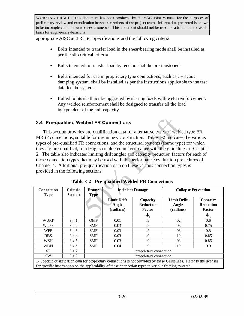
WORKING DRAFT - This document has been produced by the SAC Joint Venture for the purposes ofpreliminary review and coordination between members of the project team. Information presented is knownto be incomplete and in some cases erroneous. This document should not be used for attribution, nor as thebasis for engineering decisions
3-20 02/02/99
appropriate AISC and RCSC Specifications and the following criteria:
• Bolts intended to transfer load in the shear/bearing mode shall be installed asper the slip critical criteria.
• Bolts intended to transfer load by tension shall be pre-tensioned.
• Bolts intended for use in proprietary type connections, such as a viscousdamping system, shall be installed as per the instructions applicable to the testdata for the system.
• Bolted joints shall not be upgraded by sharing loads with weld reinforcement.Any welded reinforcement shall be designed to transfer all the loadindependent of the bolt capacity.
3.4 Pre-qualified Welded FR Connections
This section provides pre-qualification data for alternative types of welded type FRMRSF connections, suitable for use in new construction. Table 3-2 indicates the varioustypes of pre-qualified FR connections, and the structural systems (frame type) for whichthey are pre-qualified, for designs conducted in accordance with the guidelines of Chapter2. The table also indicates limiting drift angles and capacity reduction factors for each ofthese connection types that may be used with the performance evaluation procedures ofChapter 4. Additional pre-qualification data on these various connection types isprovided in the following sections.
Table 3-2 - Pre-qualified Welded FR Connections
ConnectionType
CriteriaSection
FrameType
Incipient Damage Collapse Prevention
Limit DriftAngle
(radians)
CapacityReduction
Factor
ΦI
Limit DriftAngle
(radians)
CapacityReduction
Factor
ΦC
WURF 3.4.1 OMF 0.01 .9 .02 0.6WCPF 3.4.2 SMF 0.03 .9 .06 0.75WFP 3.4.3 SMF 0.03 .9 .08 0.8RBS 3.4.4 SMF 0.03 .9 .10 0.85WSH 3.4.5 SMF 0.03 .9 .08 0.85WDH 3.4.6 SMF 0.04 .9 .10 0.9
SP 3.4.7 proprietary connection1
SW 3.4.8 proprietary connection1
1- Specific qualification data for proprietary connections is not provided by these Guidelines. Refer to the licenserfor specific information on the applicability of these connection types to various framing systems.

WORKING DRAFT - This document has been produced by the SAC Joint Venture for the purposes ofpreliminary review and coordination between members of the project team. Information presented is knownto be incomplete and in some cases erroneous. This document should not be used for attribution, nor as thebasis for engineering decisions
3-21 02/02/99
3.4.1 Welded Unreinforced Flange (WURF)
This section provides guidelines for design of unreinforced, welded flangeconnections. These connections utilize complete joint penetration (CJP) groove welds,with improvements over those used prior to the Northridge earthquake, to join beam orgirder flanges directly to column flanges. In this type of connection, no reinforcementother than weld metal, is used to join the flanges. Web joints for these connections areCJP welded. This type of connection should be used only for OMF applications, whensuch systems are permitted by the building code, or when factored drift demandspredicted by structural analysis, conducted in accordance with Chapter 4, can be shown tobe lower than the product of φiθi, where θi and φI, respectively are the values indicated inTables 3-2 and 3-3 for connection drift capacity and capacity reduction factor for theappropriate performance level. Figure 3-4 provides a typical detail for this connectiontype. These connections should be designed in accordance with the guidelines of thissection.
Figure 3-4 - Typical Detail - WUF Connection
Table 3-3 - Pre-qualification Data WUF Connections
Applicable systems OMF
Pre-qualified Drift Angle Capacity 0.02 radian - collapse prevention0.015 radian - incipient damage
Capacity Reduction Factor φ 0.6 - collapse prevention0.9 - incipient damage
Hinge location distance sh dc/2
Maximum beam size W36 x 150
Beam Material A36, A572, Gr. 50, A913 Grade 50, A992
Cover Plate Material Minimum specified yield strength equal or larger than that specified

WORKING DRAFT - This document has been produced by the SAC Joint Venture for the purposes ofpreliminary review and coordination between members of the project team. Information presented is knownto be incomplete and in some cases erroneous. This document should not be used for attribution, nor as thebasis for engineering decisions
3-22 02/02/99
for the beam material
Maximum column size unlimited
Column Steel Grades ASTM A-572, Gr. 50, ASTM A-913, ASTM A-992
Panel zone to Beam strength ratio to be determined
Column to Beam strength ratio to be determined
3.4.1.1 Procedure for Sizing Shear Tabs
Shear tabs for this type of connection should be sized with minimum thickness,number of bolts, and welding to the column as required to resist erection loads. Inaddition to serving as an erection connection, the shear tab serves as a backing for theCJP web weld and therefore, it should be continuously fillet or groove welded on the sideaway from the CJP weld.
3.4.1.2 Procedure for Weld Sizing
The basic flange to flange weld for this connection is a CJP weld. The reinforcingfillet weld, added after removal of the backing, should be a minimum of 5/16 inch.Build-up of the top of the CJP weld is recommended, to provide a minimum of 5/16 inchof reinforcing.
Commentary: There is more research information available onunreinforced beam-to-column connections than there is on any other typeof steel moment frame connection. Not only were these connectionsstudied prior to Northridge (Ref. Popov and Stephen, Popov and Amin,Englehardt and Husain, 1992 etc.), but they have been even moreextensively studied in the aftermath. Many of the studies have focused onthe connection as used in pre-1994 practice, that is, with bolted webconnection and E70T-4 flange welds, with backing left in place (Refs…..),while others have been focused on improvements to the connection,including those improvements recommended in this section.
Lu, Xue, Kaufmann and Fisher conducted a number of different testsat Lehigh, which were focused on fracture mechanics and the effects ofnotch toughness of welding electrodes. In one series of tests, four fullscale specimens using W36x150 beams (A36) and W14x311 columns(Grade 50) were tested dynamically. Specimen A-1 was fabricated withE70T-4 electrodes with backing bars left in place, a bolted webconnection, and no continuity plates. This connection was similar to somewhich fractured in the Northridge Earthquake. This specimen fractured atthe bottom flange connection at 87% of the yield moment of the beam.Specimen A-2 was similar to A-1 except that backing was removed andsmall fillet welds were added to the back side of the welds. Thisconnection showed a slightly improved performance, but still fractured at

WORKING DRAFT - This document has been produced by the SAC Joint Venture for the purposes ofpreliminary review and coordination between members of the project team. Information presented is knownto be incomplete and in some cases erroneous. This document should not be used for attribution, nor as thebasis for engineering decisions
3-23 02/02/99
only 92% of the beam yield moment. Specimens A-3 and A-4 were similarto each other in that continuity plates were added, beam webs wereattached to the column flanges with complete penetration welds, weldingwas performed with notch-tough electrodes, backing was removed andfillet welds were added to the back side of the flange welds. Thedifference between the two was that A-3 was welded with E7018 and A-4was welded with E70TG-K2 flux cored electrode, both of which havesuperior notch toughness ratings, relative to the E70T4 material.Specimens A-3 and A-4 achieved inelastic rotations in the range of .025radian. Based on these, and other similar tests they have conducted, theauthors conclude that notch toughness of weld metal is a major factor inthe performance of this type of connection and that the tests demonstrate“the need to impose a fracture toughness requirement on weld metals forfuture construction in order to insure that premature weld fracture willnot occur.” (References…..)
Studies conducted as part of the FEMA/ SAC Phase II program at theUniversity of Michigan (Goel and Stojadinovic) are further examiningthese connections to provide better understanding of the following:
1. Ductility provided by panel zone yielding;
2. Depth effects;
3. Range where FR connections with bolted webs and flanges welded with notch tough electrode can be used in the future;
4. Impact of changes in material properties of steel on connectionductility;
5. What went wrong with the pre-Northridge connection.
In this series of projects, a number of specimens were constructed,using weld metal with rated toughness and W30x99 beams. While all ofthese specimens exhibited greater ductility than typical connectionsfabricated with low toughness weld metals, none were able to achieve theamount of ductility obtained in the Lehigh tests. All of the specimensdeveloped brittle fracturing, extending across one of the beam flanges,approximately in line with the toe of the weld access hole. Finite elementstudies confirm that the beam flange at the toe of the weld access hole issubjected to very large stresses and that the severity of these stresses isdependent on a number of factors including the shape of the access holeitself, the depth of the beam section, the ratio of web section properties tototal section properties and the relative strength and flexibility of thecolumn panel zone. In the testing conducted at the University of
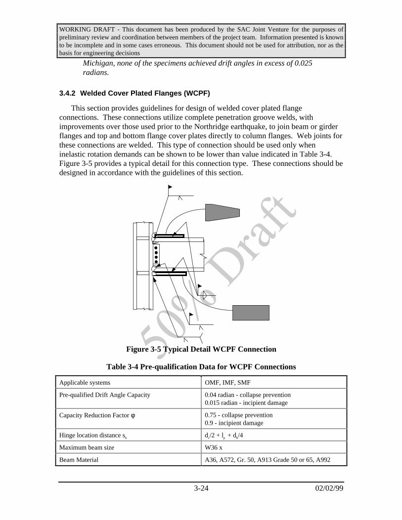
WORKING DRAFT - This document has been produced by the SAC Joint Venture for the purposes ofpreliminary review and coordination between members of the project team. Information presented is knownto be incomplete and in some cases erroneous. This document should not be used for attribution, nor as thebasis for engineering decisions
3-24 02/02/99
Michigan, none of the specimens achieved drift angles in excess of 0.025radians.
3.4.2 Welded Cover Plated Flanges (WCPF)
This section provides guidelines for design of welded cover plated flangeconnections. These connections utilize complete penetration groove welds, withimprovements over those used prior to the Northridge earthquake, to join beam or girderflanges and top and bottom flange cover plates directly to column flanges. Web joints forthese connections are welded. This type of connection should be used only wheninelastic rotation demands can be shown to be lower than value indicated in Table 3-4.Figure 3-5 provides a typical detail for this connection type. These connections should bedesigned in accordance with the guidelines of this section.
Figure 3-5 Typical Detail WCPF Connection
Table 3-4 Pre-qualification Data for WCPF Connections
Applicable systems OMF, IMF, SMF
Pre-qualified Drift Angle Capacity 0.04 radian - collapse prevention0.015 radian - incipient damage
Capacity Reduction Factor φ 0.75 - collapse prevention0.9 - incipient damage
Hinge location distance sh dc/2 + lp + db/4
Maximum beam size W36 x
Beam Material A36, A572, Gr. 50, A913 Grade 50 or 65, A992
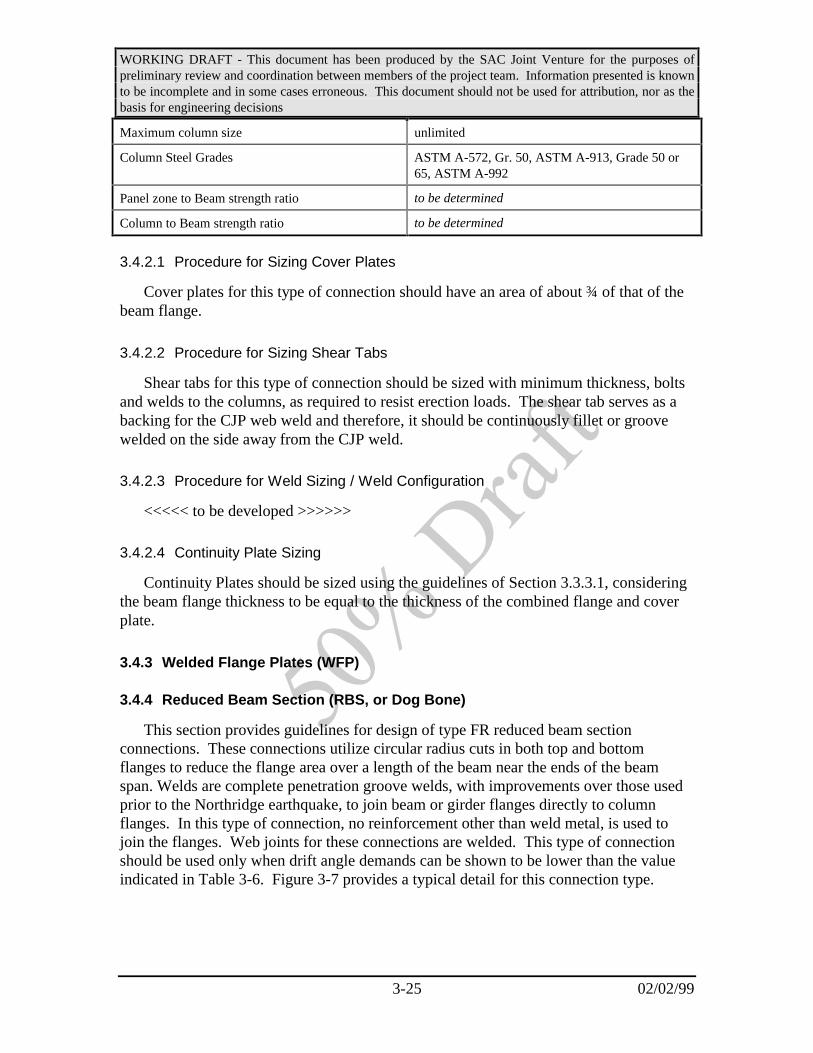
WORKING DRAFT - This document has been produced by the SAC Joint Venture for the purposes ofpreliminary review and coordination between members of the project team. Information presented is knownto be incomplete and in some cases erroneous. This document should not be used for attribution, nor as thebasis for engineering decisions
3-25 02/02/99
Maximum column size unlimited
Column Steel Grades ASTM A-572, Gr. 50, ASTM A-913, Grade 50 or65, ASTM A-992
Panel zone to Beam strength ratio to be determined
Column to Beam strength ratio to be determined
3.4.2.1 Procedure for Sizing Cover Plates
Cover plates for this type of connection should have an area of about ¾ of that of thebeam flange.
3.4.2.2 Procedure for Sizing Shear Tabs
Shear tabs for this type of connection should be sized with minimum thickness, boltsand welds to the columns, as required to resist erection loads. The shear tab serves as abacking for the CJP web weld and therefore, it should be continuously fillet or groovewelded on the side away from the CJP weld.
3.4.2.3 Procedure for Weld Sizing / Weld Configuration
<<<<< to be developed >>>>>>
3.4.2.4 Continuity Plate Sizing
Continuity Plates should be sized using the guidelines of Section 3.3.3.1, consideringthe beam flange thickness to be equal to the thickness of the combined flange and coverplate.
3.4.3 Welded Flange Plates (WFP)
3.4.4 Reduced Beam Section (RBS, or Dog Bone)
This section provides guidelines for design of type FR reduced beam sectionconnections. These connections utilize circular radius cuts in both top and bottomflanges to reduce the flange area over a length of the beam near the ends of the beamspan. Welds are complete penetration groove welds, with improvements over those usedprior to the Northridge earthquake, to join beam or girder flanges directly to columnflanges. In this type of connection, no reinforcement other than weld metal, is used tojoin the flanges. Web joints for these connections are welded. This type of connectionshould be used only when drift angle demands can be shown to be lower than the valueindicated in Table 3-6. Figure 3-7 provides a typical detail for this connection type.

WORKING DRAFT - This document has been produced by the SAC Joint Venture for the purposes ofpreliminary review and coordination between members of the project team. Information presented is knownto be incomplete and in some cases erroneous. This document should not be used for attribution, nor as thebasis for engineering decisions
3-26 02/02/99
Figure 3-6 Typical RBS Connection (Ref Englehardt)
Table 3-5 Pre-qualification Data for RBS Connections
Applicable systems OMF, IMF, SMF
Pre-qualified Drift Angle Capacity 0.04 radian - collapse prevention0.015 radian - incipient damage
Capacity Reduction Factor φ 0.85 - collapse prevention0.9 - incipient damage
Hinge location distance sh Center of Col. to Center of Reduced Sect.
Maximum beam size W36 x 194 (Largest Tested)
Beam Steel Grades ASTM A-572, Gr. 50, ASTM A-992
Maximum column size unlimited
Column Steel Grades ASTM A-572, Gr. 50, ASTM A-913, Grade 50 or65, ASTM A-992
Panel zone to Beam strength ratio to be determined
Column to Beam strength ratio to be determined
3.4.4.1 Procedure for Sizing Section Reduction
Figure 3-7 shows the geometry of a radius cut RBS, and Fig. 3-8 shows the entiremoment frame beam. The designer should select the dimensions a and b according to thefollowing guidelines:
a ≅ (0.5 to 0.75) bf (3-4)
b ≅ (0.65 to 0.85) d (3-5)

WORKING DRAFT - This document has been produced by the SAC Joint Venture for the purposes ofpreliminary review and coordination between members of the project team. Information presented is knownto be incomplete and in some cases erroneous. This document should not be used for attribution, nor as thebasis for engineering decisions
3-27 02/02/99
where bf and d are the beam flange width and depth respectively.
The remaining dimension that must be chosen when sizing the RBS is c, the depthof the cut. The value of c will control the maximum moment developed within the RBS,and therefore will control the maximum moment and shears generated at the face of thecolumn. The final dimensions should be chosen so that the maximum moment at the faceof the column is in the range of about 85 to 100 percent of the beam’s expected plasticmoment. The value of c should be chosen to be less than or equal to 0.25bf.
The radius of the cut R can be related to dimensions b and c based on thegeometry of a circular arc, using the equation in Fig. 3.8. The amount of flange materialwhich is removed at the minimum section of the RBS is sometimes referred to thepercent flange removal which is computed as (2c/bf) × 100, where bf is the unreducedflange width of the beam.
Once dimensions have been selected based on the above guidelines, calculationsusing standard methods of strength of materials and the general guidelines given insections 3.2 and 3.3 above can be used to verify that the required condition for maximummoment at the column face is met.
a b
c
c
R = radius of cut = 4c + b8c
2 2
bf
Fig. 3.7 Geometry of Radius Cut RBS (Ref. Englehardt)
ba
LC RBS
b2a + L’ = distance between centers of RBS cuts
b
LC RBS
a
b2a +
L = distance between column centerlines
w = uniform beam gravity load
Fig. 3.8 Typical Moment Frame Beam with RBS Connections (Ref. Englehardt)

WORKING DRAFT - This document has been produced by the SAC Joint Venture for the purposes ofpreliminary review and coordination between members of the project team. Information presented is knownto be incomplete and in some cases erroneous. This document should not be used for attribution, nor as thebasis for engineering decisions
3-28 02/02/99
Commentary: The above recommendations are based on the experimentaldata and the design approach recommended in Refs. (Englhardt M.D.,Winneberger, T., et al, 1996, 1997). Many of the design steps parallelrecommendations provided in Ref. (Gross, J.L., Englehardt, M.D. et al).
The guidelines presented here are only for radius cut RBS connections.Other shapes of cuts including constant cut and tapered cut have beensuccessfully tested. In some cases, fractures have occurred at the changesof section of those configurations, indicating that stress concentrationshave likely been induced by the relatively abrupt section change and alsopointing up the difficulty of avoiding fabrication caused concentrations atthose critical locations. Testing has verified the higher degree ofreliability of the radius cut RBS as compared to the other configurations.
The overall goal in sizing the RBS cut is to limit the maximum beammoment that can develop at the face of the column to values in the rangeof about 85 to 100 percent of the beam’s expected plastic momentcapacity. This approach, in effect, limits the maximum stress at the beamflange groove welds to values on the order of the actual yield stress of thebeam. Experiments (Ref. Englehardt and Winneberger, 1997) have shownthat connections detailed in accordance with the recommendationsprovided below are capable of safely resisting this level of moment. As apoint of comparison, tests on all-welded moment connections without RBScutouts often show maximum moments at the face of the column of about125 percent of Mp or greater. Consequently, the addition of the RBScutouts in the beam results in a substantial reduction in moment at theface of the column.
The guidelines for selection of RBS dimensions followrecommendations of FEMA 267and FEMA 267A, with several exceptions.Most significant of these exceptions is that FEMA 267A places a limit onthe maximum stress permitted at the face of the column equal to ninetypercent of the minimum specified yield stress of the column. For thenormal case of an A572 Gr. 50 column, this results in a limit of 45 ksi.This limit was established to address concerns regarding the potential forthrough-thickness failures in column flanges. As noted above, the designprocedure goal is to limit the maximum stress at the face of the column toa value on the order of the actual yield stress of the beam, which willtypically exceed this 45 ksi limit. The actual yield stress of either an A36or A572 Gr. 50 beam is anticipated to be in the vicinity of approximately55 ksi. This exception to the requirements of FEMA 267A has beenadopted for several reasons. First, specimens designed according to theprocedures described have performed well in laboratory tests. Second,satisfying the 45 ksi stress limit would result in excessively large flangecutouts in many cases, or would require supplemental flange

WORKING DRAFT - This document has been produced by the SAC Joint Venture for the purposes ofpreliminary review and coordination between members of the project team. Information presented is knownto be incomplete and in some cases erroneous. This document should not be used for attribution, nor as thebasis for engineering decisions
3-29 02/02/99
reinforcement such as cover plates or ribs. Further, as described insection 3.3.1 above, research conducted under the SAC Phase 2 programsuggests that the potential for through-thickness failures is considerablyless than previously thought, and it is believed that the current limit of 45ksi can be safely increased.
In past tests, the dimensions “a” and “b” have generally been chosenbased on the judgment of the researchers. In general, these dimensionsshould be kept as small as possible in order to minimize the growth ofmoment from the plastic hinge located in the RBS back to the face of thecolumn. The dimension, “a,” should be large enough, however, to permitstress in the reduced section of the beam to spread uniformly across theflange width before reaching the column face. Similarly, the dimension“b” should be large enough to avoid excessive inelastic strains within theRBS. Thus, the dimensions “a” and “b” should be chosen consideringthese differing requirements. Examination of RBS test data indicates thatsuccessful connection performance has been obtained for a wide range ofvalues for “a” and “b.”
3.4.4.2 Procedure for Sizing Shear Tabs
Shear tabs for this type of connection should be sized with minimum thickness, boltsand welds to the columns, as required to resist erection loads. The shear tab serves as abacking for the CJP web weld and therefore, it should be continuously fillet or groovewelded on the side away from the CJP weld.
If it is desired to use a welded shear tab in lieu of a direct CJP weld of the web, theshear tab and welding should be designed to provide strength and stiffness equaling thatof the fully welded web.
Commentary: It is recommended that the connection of the beam web tothe column be welded. While a welded web connection is more costly thanthe more conventional bolted web connection, it is believed that thewelded web improves the reliability of the connection. The welded webprovides for more effective force transfer through the web connection,thereby reducing stress levels at the beam flanges and beam flange groovewelds.
As an alternative to a CJP groove weld, the beam web connection canalso be made using a heavy welded shear tab. The shear tab is typicallywelded to the column using either fillet welds or a CJP groove weld. Theshear tab, in turn, is then welded to the beam web with fillet welds.

WORKING DRAFT - This document has been produced by the SAC Joint Venture for the purposes ofpreliminary review and coordination between members of the project team. Information presented is knownto be incomplete and in some cases erroneous. This document should not be used for attribution, nor as thebasis for engineering decisions
3-30 02/02/99
3.4.4.3 Procedure for Flange Weld Sizing
The basic flange to flange weld for this connection is a CJP weld. The reinforcingfillet weld, added after removal of the backing, should be a minimum of 5/16 inch.Flaring of the top of the CJP weld to provide a 5/16 inch fillet is recommended.
3.4.4.4 Fabrication Requirements
The RBS Cut is normally made by thermal cutting. The finished cut should besmooth to the touch, avoiding nicks, gouges, and other discontinuities. After the cut ismade, the surface should be ground smooth. All corners should be rounded to minimizenotch effects and in addition, cut edges should be ground in the direction of the flangelength to have a surface roughness values less than or equal to 1,000, as defined inANSI/ASME B46.1.
Commentary: Grinding parallel to the flange avoids grind marksperpendicular to the direction of stress, which can act as stress risers.
3.4.4.5 Supplemental Lateral Bracing at RBS
Supplemental lateral bracing should be placed at, or near to, the end of the RBS awayfrom the column. Welding or bolting to provide bracing at the center of the RBS shouldnot be done.
Commentary: FEMA 267A recommends that a lateral brace be providedat the RBS. This recommendation addresses the concern that a beam withRBS cuts may be prone to earlier or more severe instability than a beamwithout RBS cuts. The concern here is primarily with lateral torsionalbuckling rather than with local beam flange instability, since it isapparent that the RBS cut reduces the local b/t of the flange. Lateraltorsional buckling in the RBS connection may be worse than wasenvisioned for the old pre Northridge connection for two reasons: 1)because of the narrower flange resulting from the RBS and 2) because thehinge is moved away from the location of the natural brace provided bythe column. By providing bracing at the end of the RBS away from thecolumn and using the natural bracing provided by the column, the RBS iseffectively braced at both ends. It is felt that welding or bolting whichmight be required to connect a brace at the center of the RBS may create alocal condition which will be harmful to the performance of the desiredplastic hinge, so such bracing is not recommended. Rather, it is preferredthat bracing and other attachment to the RBS be made outside the zone ofanticipated plasticity.
There is not universal agreement that the lateral bracing described isnecessary. The following is quoted from Englehardt (Ref.____).

WORKING DRAFT - This document has been produced by the SAC Joint Venture for the purposes ofpreliminary review and coordination between members of the project team. Information presented is knownto be incomplete and in some cases erroneous. This document should not be used for attribution, nor as thebasis for engineering decisions
3-31 02/02/99
“Virtually all moment connections that dissipate energy byyielding of the beam are subject to varying degrees of beaminstability at large levels of inelastic rotation. This is true both forreinforced connections (cover plates, ribs, haunches, etc.) and forRBS connections. This instability generally involves a combinationof flange buckling, web buckling and lateral torsional buckling andtypically results in a deterioration in the flexural strength of thebeam with increasing inelastic rotations. In the experience of thewriter, the degree of instability and associated strengthdeterioration for RBS connections tested in the laboratory havebeen no more severe, and perhaps somewhat less severe than formany types of reinforced connections. This is demonstrated by theconnection test results shown in Fig. 8.
-250
-200
-150
-100
-50
0
50
100
150
200
250
-6 -4 -2 0 2 4 6
Displacement (inches)
Lo
ad (
kip
s)
Cover Plated Connection
RBS Connection
Fig.3-8 - Comparison of Test Results for Cover Plated and RBSConnections
This figure shows a plot of beam tip load versus beam tip displacementfor two different test specimens (Refs. 2 and 15). These two specimenswere virtually identical, except for the connection detail. Both specimenswere constructed with the same member sizes (W36x150 beam andW14x426 column) and heats of steel, and tested in the same test setup withidentical member lengths, identical member end support conditions, andidentical lateral bracing. Both specimens were subject to the same loadinghistory. The only difference was that one specimen was constructed with acover plated connection and the other with an RBS connection. Bothspecimens were provided with a single beam lateral support near the point

WORKING DRAFT - This document has been produced by the SAC Joint Venture for the purposes ofpreliminary review and coordination between members of the project team. Information presented is knownto be incomplete and in some cases erroneous. This document should not be used for attribution, nor as thebasis for engineering decisions
3-32 02/02/99
of load application.
As can be seen from Fig. 3-8, the peak strength of the RBS connectionis less than that of the cover plated connection. This, of course, is expectedand is in fact the advantage of the RBS in that it reduces the momentgenerated at the connection and the moment delivered to the column. Afterreaching their peak strength, both connections exhibited some strengthdeterioration due to combined flange, web and lateral torsional bucklingin the beam. Note however that the rate of deterioration is less for the RBSspecimen. In fact, at large inelastic deformations, the RBS exhibits thesame strength as the cover plated connection. This comparisondemonstrates the observation made above, i.e., RBS connections exhibit nomore strength deterioration, and perhaps somewhat less deteriorationthan reinforced connections.
The test data summarized in Appendix A indicates that many RBSconnection tests have been conducted without an additional lateral braceat the RBS. There is no instance where an investigator reported unusuallysevere or unacceptable strength deterioration due to the absence of alateral support.
Based on the available experimental data, in the judgment of thewriter, no additional lateral support is required at the RBS. Of course, thedesigner should still adhere to the normal code provisions for beamlateral support and for beam flange and web slenderness limits.”
The above opinion notwithstanding, it is worth noting that in someearly testing of RBS connections, conducted for the AISC at Smith-Emerylaboratories, testing of the connection assembly was halted atapproximately 0.04 radians total deformation due to the development oflarge lateral torsional twisting of the beam section and concern that thelaboratory apparatus would be damaged. Based on this, these guidelinesrecommend that lateral bracing for compression flanges be provided.
3.4.5 Welded Single Haunch (WSH)
<<<<< to be developed >>>>>>
3.4.6 Welded Double Haunch (WDH)
<<<<< to be developed >>>>>>
3.4.7 Side Plate (SP)
This proprietary connection is shown schematically in Figure 3-9. Beam shear and

WORKING DRAFT - This document has been produced by the SAC Joint Venture for the purposes ofpreliminary review and coordination between members of the project team. Information presented is knownto be incomplete and in some cases erroneous. This document should not be used for attribution, nor as thebasis for engineering decisions
3-33 02/02/99
flexural stresses are transferred to a pair of vertical side plates that sandwich both thebeam and column in the connection area. The plates than transfer these stresses to thecolumn, primarily through shear behavior. The plates are designed with adequatestrength to force plastic behavior of the connection assembly into the beam span, adjacentto the edge of the side plates. Specific qualification and design information for thisconnection type may be obtained from the licenser.
Figure 3-9 Proprietary Side Plate Connection
3.4.8 Slotted Web (SW)
This proprietary connection is shown schematically in Figure 3-10. It is similar inconfiguration to the WURF connection of Section 3.4.1 except that horizontal slots arecut into the ends of the beam web at the k region of the shape. The slots reduce stressconcentrations in the beam flange to column flange joint and also promote buckling of thebeam flanges to limit load delivered to these welded joints. Specific qualification anddesign information for this connection type may be obtained from the licenser.
Figure 3-10 Proprietary Side Plate Connection
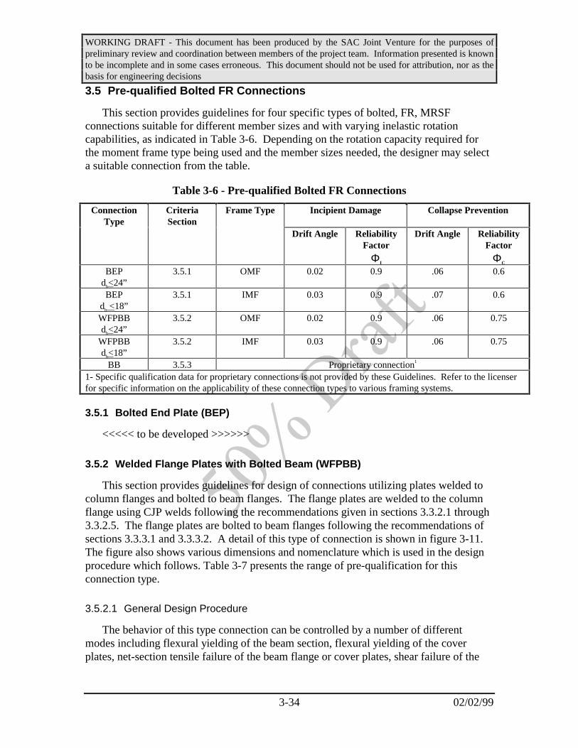
WORKING DRAFT - This document has been produced by the SAC Joint Venture for the purposes ofpreliminary review and coordination between members of the project team. Information presented is knownto be incomplete and in some cases erroneous. This document should not be used for attribution, nor as thebasis for engineering decisions
3-34 02/02/99
3.5 Pre-qualified Bolted FR Connections
This section provides guidelines for four specific types of bolted, FR, MRSFconnections suitable for different member sizes and with varying inelastic rotationcapabilities, as indicated in Table 3-6. Depending on the rotation capacity required forthe moment frame type being used and the member sizes needed, the designer may selecta suitable connection from the table.
Table 3-6 - Pre-qualified Bolted FR Connections
ConnectionType
CriteriaSection
Frame Type Incipient Damage Collapse Prevention
Drift Angle ReliabilityFactor
ΦI
Drift Angle ReliabilityFactor
ΦC
BEPdb<24”
3.5.1 OMF 0.02 0.9 .06 0.6
BEPdb <18”
3.5.1 IMF 0.03 0.9 .07 0.6
WFPBBdb<24”
3.5.2 OMF 0.02 0.9 .06 0.75
WFPBBdb<18”
3.5.2 IMF 0.03 0.9 .06 0.75
BB 3.5.3 Proprietary connection1
1- Specific qualification data for proprietary connections is not provided by these Guidelines. Refer to the licenserfor specific information on the applicability of these connection types to various framing systems.
3.5.1 Bolted End Plate (BEP)
<<<<< to be developed >>>>>>
3.5.2 Welded Flange Plates with Bolted Beam (WFPBB)
This section provides guidelines for design of connections utilizing plates welded tocolumn flanges and bolted to beam flanges. The flange plates are welded to the columnflange using CJP welds following the recommendations given in sections 3.3.2.1 through3.3.2.5. The flange plates are bolted to beam flanges following the recommendations ofsections 3.3.3.1 and 3.3.3.2. A detail of this type of connection is shown in figure 3-11.The figure also shows various dimensions and nomenclature which is used in the designprocedure which follows. Table 3-7 presents the range of pre-qualification for thisconnection type.
3.5.2.1 General Design Procedure
The behavior of this type connection can be controlled by a number of differentmodes including flexural yielding of the beam section, flexural yielding of the coverplates, net-section tensile failure of the beam flange or cover plates, shear failure of the

WORKING DRAFT - This document has been produced by the SAC Joint Venture for the purposes ofpreliminary review and coordination between members of the project team. Information presented is knownto be incomplete and in some cases erroneous. This document should not be used for attribution, nor as thebasis for engineering decisions
3-35 02/02/99
Table 3-7 Pre-qualification Data for WFPBB Connections
Applicable systems Mode 1: OMF, IMF, SMFMode 2: OMF, IMF
Pre-qualified Drift Angle Capacity Mode 1: 0.04 radian - collapse preventionφ = 0.750.015 radian - incipient damageφ = 0.9
Mode 2: 0.03 radian - collapse preventionφ = 0.750.015 radian - incipient damageφ = 0.9
Hinge location distance sh Mode 1: - S1+S3+db/2Mode 2: - S1/2
Maximum beam size W24 x 94
Beam Material A36, A572, Gr. 50, A913 Grade 50 or 65, A992
Plate Material A36, A572, Gr. 50, A992
Maximum column size unlimited
Column Material A36, A572, Gr. 50, A913 Grade 50 or 65, A992
Panel zone to Beam strength ratio to be developed
Column to Beam strength ratio to be developed
SN
S3 221= −
Total Number of Bolts
Beam length betweenfaces of columns

WORKING DRAFT - This document has been produced by the SAC Joint Venture for the purposes ofpreliminary review and coordination between members of the project team. Information presented is knownto be incomplete and in some cases erroneous. This document should not be used for attribution, nor as thebasis for engineering decisions
3-36 02/02/99
Figure 3-11 Welded Flange Plate Bolted Beam Connection
bolted connections, etc., depending on the relative proportions of these variouscomponents. Some of these modes are quite brittle, while others have the ability todisplay significant ductility. Two behavioral modes are permitted under the pre-qualification for this connection type:
• Mode 1 - Flexural yielding of beam, within span, adjacent to cover plates
• Mode 2 - Flexural yielding of cover plates, adjacent to the column
Regardless of the controlling behavioral mode selected for the connection, it isnecessary for the design to satisfy the following relationships:
• The moment at the face of the column, as controlled by yielding in the desiredbehavioral mode, Myd, must be less than the corresponding moment at the faceof the column for yielding of any of the other failure modes, Myi.
• The upper bound moment at the face of the column, as controlled by yieldingin the desired behavioral mode, but considering potential over-strength andstrain hardening must be less than the moment at the face of the columncorresponding with failure of any of the other behavioral modes.
The procedure for calculating the moment at the face of the column, correspondingwith yield and failure of each of these behavioral modes is indicated in Sections 3.5.2.2through 3.5.2.7. The parameters used in these equations are defined in Figure 3-9.
3.5.2.2 Bolt Shear
The moment at the column face, when bolt shear failure occurs at the center line ofthe bolt group, should be calculated using the following equation:
Failure: ( ) ( )( )M NA F d t tL
L SN
Sfail b u bolt b pl top pl bot= + +
− + −
− − −. .
.
62 5
52
11 2
(3-6)
where Ab is the cross sectional area of one bolt. It is assumed that all bolts are of thesame diameter.
The moment at the face of the column, when yielding elongation of the bolt holesoccurs shall be calculated using the following equation:
Yield: M T d t tL
L SN
Syield n b pl t pl b= + +
− + −− −( . ( )
( . ( ) )5
52
11 2
(3-7)

WORKING DRAFT - This document has been produced by the SAC Joint Venture for the purposes ofpreliminary review and coordination between members of the project team. Information presented is knownto be incomplete and in some cases erroneous. This document should not be used for attribution, nor as thebasis for engineering decisions
3-37 02/02/99
where Tn is the nominal tensile or compressive force in the flange developed when thebolts develop their strength, in accordance with the AISC Load and Resistance Factordesign provisions. In addition, Tn shall be calculated using the procedures of the AISCLRFD provisions (Ref. ) for calculating block shear capacity See Fig. 3-12 for failuretypes to be checked.
Figure 3-12 Block Shear and Pull Through Failures
3.5.2.3 Flange Plate
The moment at the column face corresponding to flange plate fracture at the netsection in the row of bolts nearest to the column face, shall be calculated using thefollowing equation:
Failure: ( ) ( )M F b t d tL
L Sfail u pl p bolt pl b pl= − + +−−. ( .85 2 125
1
φ (3-8)

WORKING DRAFT - This document has been produced by the SAC Joint Venture for the purposes ofpreliminary review and coordination between members of the project team. Information presented is knownto be incomplete and in some cases erroneous. This document should not be used for attribution, nor as thebasis for engineering decisions
3-38 02/02/99
The moment at the column face corresponding to flange plate yielding between thecolumn face and the first row of bolts shall be calculated using the following equation:
Yield: M R F t b d t tL
LSyield y y pl pl p b pl t pl b= + +
−− − −11 5
21
. ( . ( ) (3-9)
3.5.2.4 Beam Flange
The moment at the column face associated with fracture of the beam at the net sectionat the last row of bolts away from the column face should be calculated using thefollowing equation:
Failure: ( ) ( ) ( )( )M F b t d t F A b t dL
L SN
Sfail u bm f bolt pl b f y bm bm f f b tf= − + − + − −
− + −
− −2 125 25 2 2
211 2
φ . . (3-10)
The moment at the column face associated with yielding of the beam at the net sectionat the last row of bolts away from the column face should be calculated using thefollowing equation:
Yield: M ZR FL
L SN
Syield y ybm=
− + −11
211 2
.( ( )
(3-11)
3.5.2.5 Groove Weld
The moment at the column face associated with fracture of the CJP groove weld shallbe calculated using the following equation:
Failure: M F t dt t
fail u weld e b
pl t pl b=+
−− −
( )2
(3-12)
3.5.2.6 Panel Zone
The moment at the face of the column associated with yielding of the column panelzone shall be calculated using the following equation:
Yield: Myield d R F d tb y y col c w c= − −. ( . )5225 11 (3-13)
Commentary: The methodology for design of this type of connection stillrequires a significant amount of development. The information providedabove primarily is interpreted from the 50% SOA Report on ConnectionPerformance. Additional research is now underway by Schneider which is

WORKING DRAFT - This document has been produced by the SAC Joint Venture for the purposes ofpreliminary review and coordination between members of the project team. Information presented is knownto be incomplete and in some cases erroneous. This document should not be used for attribution, nor as thebasis for engineering decisions
3-39 02/02/99
expected to answer many of the remaining questions. In the interim, thiscommentary includes a summary of important points for consideration.
The draft SOA provides the basic design equation as Mfail < Myield,suggesting that any yielding mode may be selected for the control of theconnection design and that all other elements of the connection must bedesigned to allow them to safely develop the yield strength of the selectedmode. This is fine as far as it goes, but it is well recognized that themoment at first yield and that at the required plastic rotation are not thesame thing. It is also recognized that each of the yield mechanisms willnot have the same relationship of yield strength to failure strength, so thattypically in these connections, inelastic behavior will be controlled bycombinations of yield mechanisms in several behavior modes, each oneoccurring successively as strain hardening occurs in earlier ones, untilsuch time as failure occurs.
1. What is the relationship of yield overstrength to Fu overstrengthfor a given member? Should we use Fye with Fu (nominal), or isthis too conservative? Research from the materials and fractureteam indicates that there is no direct relationship between yieldand ultimate overstrength, although the ASTM specifications docontrol, for a given piece of material the ratio of yield to tensilestrength.
2. How does strain hardening come into the picture? It is probablethat if Myield is defined as including yield overstrength and a strainhardening factor, while Fu is nominal, it will not be practical todesign these connections. But, will it be conservative enough to dootherwise? In reality, depending on the design, the first yieldmechanism to occur may partially strain harden and then anotheryield mechanism will reach its first yield, and so on. Somewhere inthis process, the lowest strength, Mfail will be achieved. Theproblem is how to decide on an appropriate rotation angle theconnection will reach through this complex process.
3. In the equation provided for calculation of Myield controlled bybeam flange yielding, it is assumed that the plastic hinge will occurat the row of bolts farthest from the column face. The tableindicates that the Plastic Rotation Limit is “same as the beam.” Isit true that one could get a rotation of say .04 radians(approximate capability of the beam itself) at the location of thebolt holes? It seems unlikely to me. Maybe this would be possibleif the conservative approach in 1 above were used.
4. The equation for “Panel Zone Yielding” considers only the column

WORKING DRAFT - This document has been produced by the SAC Joint Venture for the purposes ofpreliminary review and coordination between members of the project team. Information presented is knownto be incomplete and in some cases erroneous. This document should not be used for attribution, nor as thebasis for engineering decisions
3-40 02/02/99
web. In this case it may be appropriate to use the conservative(higher) strength for this mechanism (e.g. the Krawinkler Formula)since the Myield is on the left side of the inequality. As it is in thetable, an innocent designer would decide to use panel zoneyielding as his mechanism to get .025 radians of plastic rotationwhile assuming that the Myield formula given would precludereaching the lowest calculated Mfail. Again, the problem is that theformula is expressing first yield for the panel zone, so we are leftwith the need to know at what point in its strain hardening andgradual utilization of the flange strength other yield mechanismsor failure mechanisms occur, in order to know how much plasticrotation the connection can derive from the column panel zone.
5. It is not clear that we can make any use of “block shear yielding”,it just adds to the complexity expressed by the questions above.This is not to suggest that it should not be discussed in the SOAreport.
Considering all of the above, it seems like the only reasonableapproach to making a predictable design for these connections is to pickone, or at most two, yield mechanisms that are predictable, determinetheir expected strength at the required rotation (or at the peak if it occursbefore the required rotation is achieved), and conservatively assure thatthese are lower than the lowest Mfail. This is the approach that has takenin this draft of the Guidelines. For example, if we use an A36 flange platesized to yield after the panel zone first yield, but before it reaches its peakcapacity, and calculate its strain hardened strength at the requiredrotation (less the rotation provided by the panel zone) and keep themoment at the column face at this strength less than the lowest Mfail, theconnection may be successful. This of course, brings up another problem:the effect of a given panel zone rotation on the capacity of the flange platewelds needs to be defined.
3.5.3 Bolted Bracket (BB)
This connection type is shown schematically in Figure 3-13. Beam shear and flexuralstresses are transferred to the column through a pair of heavy, bolted brackets, located atthe top and bottom beam flanges. The concept of using bolted brackets to rigidly connectbeams to columns is within the public domain, however, generic pre-qualification datahave not been developed for this connection type. One licenser has developed patentedsteel castings of the bolted brackets, for which specific design qualification data has beenprepared. Specific qualification and design information for this connection type may beobtained from the licenser.

WORKING DRAFT - This document has been produced by the SAC Joint Venture for the purposes ofpreliminary review and coordination between members of the project team. Information presented is knownto be incomplete and in some cases erroneous. This document should not be used for attribution, nor as thebasis for engineering decisions
3-41 02/02/99
Figure 3-13 Bolted Bracket Connection
3.6 Pre-qualified PR Connections
This section provides guidelines for pre-qualified Partially Restrained (PR) MRSFconnections suitable for different member sizes and with varying inelastic rotationcapabilities, as indicated in Table 3-8. Depending on the rotation capacity required forthe moment frame type being used and the member sizes needed, the designer may selecta suitable connection from the types described in the following paragraphs. If aconnection type other than one of the pre-qualified connections is to be used, it should bequalified by tests as described later in this section.
Table 3-8 - Pre-qualified Bolted PR Connections
Connection Type CriteriaSection
FrameType
Incipient Damage Collapse Prevention
Drift Angle -IncipientDamage
ReliabilityFactor
ΦI
Drift Angle -IncipientDamage
ReliabilityFactor
ΦC
DSTdb<30”
3.6.1 IMF .08 0.75
DSTdb <24”
3.6.1 SMF .10 0.75
STCdb<30”
3.6.2 .
STCdb<24”
3.6.2
SLCdb<30”
3.6.3 .
SLCdb<24”
3.6.3 OMF .10 0.75
SCdb<24”
3.6.4 * .10 0.85
SCdb<18”
3.6.4 * .12 0.9

WORKING DRAFT - This document has been produced by the SAC Joint Venture for the purposes ofpreliminary review and coordination between members of the project team. Information presented is knownto be incomplete and in some cases erroneous. This document should not be used for attribution, nor as thebasis for engineering decisions
3-42 02/02/99
3.6.1 Double Split Tee Connections (DST)
This section provides guidelines for design of type PR connections employing boltedsplit tee connectors between the beam and column flanges. This type of connectionshould be used only when design parameters are within the limitations indicated in Table3-9. Figure 3-14 provides a typical detail for this connection type. The design procedureof this section should apply.
Figure 3-14- Typical Double Split Tee Connection
Table 3-9 - Pre-qualification Data for DST Connections
Applicable systems OMF, IMF, SMF
Pre-qualified Inelastic Rotation Demand 0.10 radian - collapse preventionφ = 0.750.03 radian - incipient damageφ = 0.9
Hinge location distance sh dc/2
Maximum beam size W36 x 150
Beam Material A36, A572, Gr. 50, A913 Grade 50 or 65, A992
Maximum column size unlimited
Column Material A36, A572, Gr. 50, A913 Grade 50 or 65, A992
Connection Stiffness 10EI/Lb
Connection Strength (fraction of Beam Mp) 30%

WORKING DRAFT - This document has been produced by the SAC Joint Venture for the purposes ofpreliminary review and coordination between members of the project team. Information presented is knownto be incomplete and in some cases erroneous. This document should not be used for attribution, nor as thebasis for engineering decisions
3-43 02/02/99
3.6.1.1 Procedure for Sizing Tees
<<<<< to be developed >>>>>>
3.6.1.2 Procedure for Sizing Bolts to Column Flange
<<<<< to be developed >>>>>>
3.6.1.3 Procedure for Sizing Bolts to Beam Flange
<<<<< to be developed >>>>>>
3.6.2 Single Tee Composite (STC) Connection
This section provides guidelines for design of type PR connections employing boltedsplit tee connectors at the beam bottom flange to column flange joint and utilizing areinforced composite floor slab to transfer beam top flange forces.. This type ofconnection should be used only when design parameters are within the limitationsindicated in Table 3-10. Figure 3-15 provides a typical detail for this connection type.
Figure 3-15 - Typical Single Tee Composite Connection
Table 3-11 - Pre-qualification Data for DST Connections
Applicable systems OMF, IMF, SMF
Pre-qualified Inelastic Rotation Demand 0.10 radian - collapse preventionφ = 0.750.03 radian - incipient damageφ = 0.9
Hinge location distance sh dc/2

WORKING DRAFT - This document has been produced by the SAC Joint Venture for the purposes ofpreliminary review and coordination between members of the project team. Information presented is knownto be incomplete and in some cases erroneous. This document should not be used for attribution, nor as thebasis for engineering decisions
3-44 02/02/99
Maximum beam size W36 x 150
Beam Material A36, A572, Gr. 50, A913 Grade 50 or 65, A992
Maximum column size unlimited
Column Material A36, A572, Gr. 50, A913 Grade 50 or 65, A992
Connection Stiffness 10EI/Lb
Connection Strength (fraction of Beam Mp) 30%
3.6.2.1 Procedure for Sizing Tees
<<<<< to be developed >>>>>>
3.6.2.2 Procedure for Sizing Bolts to Column Flange
<<<<< to be developed >>>>>>
3.6.2.3 Procedure for Sizing Bolts to Beam Flange
<<<<< to be developed >>>>>>
3.6.2.4 Procedure for Sizing Shear Studs
<<<<< to be developed >>>>>>
3.6.2.5 Procedure for Sizing Slab Reinforcement
<<<<< to be developed >>>>>>
3.6.3 Single Angle Composite (SLC)
<<<<< to be developed >>>>>>
3.6.4 Shear Tab Composite (SC)
<<<<< to be developed >>>>>>
3.7 Non-pre-qualified Connections
This section provides guidelines for design and project-specific qualification ofconnections for which there is no current pre-qualification or for pre-qualifiedconnections which are to be utilized outside the parametric limitations for the pre-qualification as indicated in the guidelines above. Project-specific qualification includesa program of connection assembly prototype testing supplemented by a suitable analytical

WORKING DRAFT - This document has been produced by the SAC Joint Venture for the purposes ofpreliminary review and coordination between members of the project team. Information presented is knownto be incomplete and in some cases erroneous. This document should not be used for attribution, nor as thebasis for engineering decisions
3-45 02/02/99
procedure that permits prediction of behaviors identified in the testing program.
Commentary: This suggests that for non-pre-qualified connections, bothlaboratory testing and the development of an analytical procedure thatpredicts the behavior is required. The intent is to provide a designprocedure applicable to the design of connections employing slightlydifferent members than actually tested. This is similar to the intent of theCounty of L.A. requirements and more rigorous than contained in theFEMA-267 Guidelines.
While it is not the intent of the Guidelines to require testing for mostsituations, there will arise circumstances, where proposed connections donot satisfy pre-qualification requirements. In these situations, therequirement for testing reflects the view that the behavior of connectionsunder severe cyclic loading cannot be reliably predicted by analyticalmeans alone.
Testing is costly and time consuming, and these Guidelinerecommendations attempt to keep testing requirements as simple aspossible. These tests attempt to account for the behavior of manyvariables whose behavior is understood imprecisely, and the testconditions should match the conditions in the structure as closely aspossible. Where conditions in the structure differ significantly from theconditions implied in this section, additional testing, which is beyond thescope of these Guidelines, may be required.
3.7.1 Testing Procedure
The testing program should follow the general requirements of AISC Appendix S,except that testing should be continued until connection assembly failure occurs. Theprogram should include tests of multiple specimens and should be used to predict themedian value of the inter-story drift angle capacity for both the incipient damage andcollapse prevention states, together with corresponding resistance factors. The inter-storydrift angle capacity, θ, shall be defined as indicated in Figure 3-16. The capacity shall betaken as indicated in Table 3-12.

WORKING DRAFT - This document has been produced by the SAC Joint Venture for the purposes ofpreliminary review and coordination between members of the project team. Information presented is knownto be incomplete and in some cases erroneous. This document should not be used for attribution, nor as thebasis for engineering decisions
3-46 02/02/99
cL
cL
Beam span center line
∆CL
LCL
θ CL
CLL= ∆lh
Figure 3-16 - Angular Rotation of Test Assembly
Table 3-12 Inter-story Drift Capacity
Performance Level Inter-story Drift Capacity
Incipient Damage Taken at that value of θ, per Figure 3-13, at which peak loadresistance occurs.
Collapse Prevention Taken at that value of θ, per Figure 3-13, at which connectiondamage is so severe that continued ability to remain stable undergravity loading is uncertain.
Commentary: The AISC Seismic Provisions (Ref. ) have been adoptedby reference into the 1997 NEHRP Recommended Provisions and are alsobeing considered for adoption for use with the 1997 UBC. The AISCSeismic Provisions include, and require the use of, Appendix S –Qualifying Cyclic Tests of Beam-to-Column and Link-to-ColumnConnections for qualification of connections which are not pre-qualified.Appendix S includes a complete commentary on the requirements, thus noadditional commentary is provided here.
3.7.2 Analytical Prediction of Behavior
Connection qualifications should include development of an analytical procedure topredict the behavior of the connection assembly, as demonstrated by the qualificationstests. The analytical procedure should permit identification of the strength anddeformation demands on various elements of the assembly at the various stages ofbehavior and should identify the critical load limiting mechanisms. The analyticalprocedure should be sufficiently detailed to permit design of connections employing

WORKING DRAFT - This document has been produced by the SAC Joint Venture for the purposes ofpreliminary review and coordination between members of the project team. Information presented is knownto be incomplete and in some cases erroneous. This document should not be used for attribution, nor as thebasis for engineering decisions
3-47 02/02/99
similar, but not identical members, to those tested.
Commentary: It is important for the designer to have anunderstanding of the limiting behaviors of any connection detail so that itmay be designed and specified on a rational basis for assemblies thatdiffer in configuration from those tested.
3.7.3 Determination of Resistance Factor
A resistance factor shall be determined for each performance level, using theprocedures of this section. For each performance level, a tabulation shall be made of theinter-story drift angle obtained from each of the tests, together with the natural logarithmof these inter-story drift values. The median value shall be selected. The standarddeviation of the natural logarithms of the test values, σln(t), shall be determined. Theresistance factor shall be calculated from the equation:
φσ
=− +
−ek
b Ntln( )
( )2
21
1
1(3-15)
where: k = the slope of the hazard curve for the project site, plotted in natural logarithmic coordinates. The value of k may be taken as 3 for any site
σln(t) = the standard deviation of the natural logarithms of the inter-story drift capacities obtained from the test program
b = is a parameter that relates increasing ground shaking intensity toincreasing inter-story drift demand. The value of b may be taken as 1.0.
N = the number of tests of the connection assembly contained in the data base
The value of φ need not be taken as less than 0.75 for the incipient damage state, orless than 0.5 for the collapse prevention state, which values may be used for anyconnection.
Commentary: The procedure for calculation of the resistance factorscontained in this section is based on Proposed Statistical and ReliabilityFramework for Comparing and Evaluating Predictive Models forEvaluation and Design, and Critical Issues in Developing suchFramework. Report No. SAC/BD-9703, August 27, 1997, by Wen andFoutch, and on Performance Based Analysis and Design Procedure forMoment Resisting Steel Frames, September, 1998, by Hamburger andCornell.

WORKING DRAFT - This document has been produced by the SAC Joint Venture for the purposes ofpreliminary review and coordination between members of the project team. Information presented is knownto be incomplete and in some cases erroneous. This document should not be used for attribution, nor as thebasis for engineering decisions
4-1 2/2/99
4. Performance Evaluation
4.1 Scope
This Chapter provides guidelines for performance evaluation of new MRSF structuredesigns. It includes definition of performance objectives, discussions of expectedperformance for different design levels, and discussions of performance evaluationprocedures and reliability. The guidelines of this chapter may be used in two ways. First,they may be used in an iterative process to design for performance objectives other thanthose that serve as defaults in the building code. Alternatively, the guidelines of thischapter may be used to evaluate on a building specific basis, the level of confidence withwhich a given design will actually be able to achieve specific performance objectives.The performance evaluation guidelines contained in this chapter are not intended topermit the design and construction of structures that do not, as a minimum, meet the basicstrength and stiffness requirements of the building code.
Commentary: The building code provisions do not include any specificrequirement to undertake a performance evaluation as part of the designprocess, other than to ensure that the structure is capable of providing theminimum strength to resist lateral forces specified for the applicableSeismic Design Category and to provide sufficient stiffness to respond todesign earthquake ground motion specifications within the permissibledrift limits for the applicable Seismic Use Group. The strength andstiffness evaluation requirements contained in the code are intended toprovide a high degree of confidence that SUG-I structures will notexperience collapse under Maximum Considered Earthquake groundmotions. As indicated in Figure 2-1, commentary to the NEHRPProvisions implies that structures that are adequately designed andconstructed in accordance with the Provisions, should be capable ofproviding other levels of performance for more likely (and less severe)ground motions. The Figure similarly indicates that for structuresdesigned for the requirements of other Seismic Use Groups, other superiorperformance is expected to be achieved.
Although the NEHRP Commentary implies such performance forstructures designed in accordance with the provisions, no effort has everbeen made, other than observation of the actual behavior of buildingscomplying with the code, to determine the adequacy or reliability of theProvisions in actually meeting the implied performance capability.
The performance evaluation procedures of this Chapter arerecommended to be followed as part of the design of any structure forwhich it is desired to obtain seismic performance with known reliability,
WORKING DRAFT - This document has been produced by the SAC Joint Venture for the purposes ofpreliminary review and coordination between members of the project team. Information presented is knownto be incomplete and in some cases erroneous. This document should not be used for attribution, nor as thebasis for engineering decisions
4-2 2/2/99
or for which it is desired to obtain performance other than that indicatedin Figure 2-1 for the various Seismic Use Groups.
Performance is evaluated in these guidelines based on two basic typesof parameters. The first of these is the inter-story drift induced in thestructure by the design ground motion. Inter-story drift of MRSFstructures is closely related to rotation (elastic and inelastic) demands onindividual beam-column connections, and therefore, is closely related toperformance. Conventional analytical evaluations of MRSF structuresinherently assume that the structures remain integral and stablethroughout the response. This assumption is generally valid, unless P-∆instability, or column failure occurs, either through tensile failure ofsplices or local buckling failure occurs. The potential for P-∆ instabilityis directly considered by these guidelines in the establishment ofacceptance criteria for inter-story drift. The potential for column splice orbuckling failures must be evaluated separately.
It is the intent of these guidelines that structures designed andconstructed in accordance with the guidelines would provide a highdegree of confidence that the desired performance objectives will be met.Specifically, it is intended that there be less than a 5% chance(95%confidence level) that structures that comply with the performanceevaluations contained in these guidelines would experience more severedamage than indicated within the selected hazard return period. Theguidelines of this chapter permit this confidence to be evaluated on abuilding specific basis, and also permit design for alternative performanceand alternative levels of confidence.
It is not intended that the performance evaluation guidelines containedin this chapter be used as a means of designing structures that do notconform to the applicable building code requirements. The performanceacceptance criteria contained in these guidelines presume that the basicstrength of the structure, the compactness of sections and other features ofthe building design conform to the basic code requirements.
4.2 Performance Definition
In these guidelines, performance is defined in terms of performance objectives. Eachperformance objective consists of the specification of an earthquake performance level,and an acceptable probability of exceeding that performance level within a 50 yearperiod. Buildings may be evaluated and designed to meet multiple performanceobjectives, such as a non-collapse (termed near-collapse in FEMA-303 and collapseprevention in FEMA-273)) performance with a probability of exceedance of 2% in 50years, and a non-damage condition (termed immediate occupancy in FEMA-273 andFEMA-303) for other probabilities of exceedance, for example 50% in 50 years.

WORKING DRAFT - This document has been produced by the SAC Joint Venture for the purposes ofpreliminary review and coordination between members of the project team. Information presented is knownto be incomplete and in some cases erroneous. This document should not be used for attribution, nor as thebasis for engineering decisions
4-3 2/2/99
Commentary: These guidelines adopt, with modification, the performancedefinition and evaluation approaches contained in the FEMA-273 NEHRPRehabilitation Guidelines. In the FEMA-273 Guidelines, three discretestructural performance levels are defined. These are termed: collapseprevention, life safety and immediate occupancy.
The collapse prevention performance level represents a damage stateof near complete damage, though the building has experienced neitherpartial or total collapse. Damage sustained has substantially degradedboth the stiffness and strength of the structure to resist additional lateralloading and the structure is unsafe for occupancy until shored or repaired,which may be impractical to accomplish.
The life safety level is a performance state in which significant damagehas been sustained, however, margin remains against either partial ortotal collapse. A building meeting this level of performance has notendangered the safety of occupants during response to the earthquake andmay or may not be safe for re-occupancy prior to repair or temporarybracing of the structure. In the FEMA-273 Guidelines, the life safetyperformance level is conceptually envisaged to occur at ¾ of the buildingresponse to ground motion that would produce collapse preventionperformance. In the FEMA-302/303 NEHRP Recommended Provisionsand Commentary, life safe performance is deemed to occur at structuralresponse levels that are 2/3 those at which collapse preventionperformance occurs. Due to the somewhat arbitrary definition of thisperformance level, and the fact that different guidelines and codes havehistorically selected alternative definitions for this performance, theseSAC guidelines do not utilize this performance level. Instead only theCollapse Prevention and Incipient Damage levels are addressed by theseguidelines. User’s desiring to evaluate building designs for alternativeperformance may do so by interpolating between the criteria provided forthese two levels.
The Immediate Occupancy performance level in FEMA-273 representsa performance state in which relatively little damage has occurred and inwhich the structure retains nearly all of its initial strength and stiffness.Buildings meeting this performance level represent a negligible risk to lifesafety, both during and after the earthquake event. In these guidelines,this performance level is known as Incipient Damage.
In addition to the specification of a performance level, thespecification of performance in FEMA-273 guidelines require thespecification of both a performance level, as discussed above, and also aground motion at which that performance level is to be obtained. Thus, aperformance objective in the FEMA-273 document may be expressed as -

WORKING DRAFT - This document has been produced by the SAC Joint Venture for the purposes ofpreliminary review and coordination between members of the project team. Information presented is knownto be incomplete and in some cases erroneous. This document should not be used for attribution, nor as thebasis for engineering decisions
4-4 2/2/99
the building shall obtain collapse prevention performance for groundshaking demands with a 2% probability of exceedance in 50 years.” Thisimplies a rather deterministic approach to performance achievement - “ifground motion with a severity that has a 2% probability of exceedance in50 years is experienced - the building will not experience performance inexcess of the collapse prevention level.” These guidelines take asomewhat different approach, that recognizes the uncertainties inherentboth in prediction of the ground shaking, and also the structure’sperformance.
In the approach taken in these guidelines, rather than specifying that aperformance level not be exceeded for ground shaking with a givenprobability of exceedance; performance objectives are defined as theprobability that the performance level itself not be exceeded with givenprobability, taking into account the hazards at the site. Thus performanceobjectives are expressed in the form:
• Collapse Prevention performance with a 2% probability ofexceedance in 50 years
• Incipient Damage performance with a 50% probability ofexceedance in 50 years
Although these performance definitions appear quite similar to thosecontained in FEMA-273, they are actually quite different. The primarydifference is that these definitions recognize that there is a distribution ofprobabilities that the desired performance level will be exceeded, as afunction of ground motion severity. Thus, the fact that there is someprobability that a given performance level would be exceeded at groundmotions less than those having a specific probability of exceedance can bedirectly recognized by integrating the distribution of probable buildingperformance with the distribution of probable ground shaking demands atvarious exceedance probabilities. This process is transparent to the userof these guidelines, except through the assignment of load and resistancefactors, λ and φ, which are products of the integration of the distributionsof structural performance and hazard. The user has the option, either ofusing the default load and resistance factors contained in these guidelines,or alternatively, by computing their own factors using proceduresdescribed herein. The calculation of project specific load and resistancefactors may be beneficial for some buildings, in that it will result inattainment of a higher confidence of meeting a desired performanceobjective, through the application of reduced load factors and increasedresistance factors.
One of the benefits of the performance definition approach taken by

WORKING DRAFT - This document has been produced by the SAC Joint Venture for the purposes ofpreliminary review and coordination between members of the project team. Information presented is knownto be incomplete and in some cases erroneous. This document should not be used for attribution, nor as thebasis for engineering decisions
4-5 2/2/99
these guidelines is that it permits a level of confidence with regard toattainment of the desired performance to be established. Neither theFEMA-273 Guidelines or the FEMA-302 NEHRP Provisions are able toestablish a confidence level for the attainment of specified performance.In general, the design provisions contained in these Guidelines areintended to provide a 95% confidence level with regard to attainment ofspecified performance. That is, it is expected that fewer than 5 out of 100structures designed in accordance with the guidelines of Chapters 2 and 3of this document, would experience damage exceeding the desired levelmore often than specified (e.g. Collapse Prevention at a 10% probabilityof exceedance in 50 years, rather than a 2% probability of suchexceedance).
This chapter of the guidelines provides procedure for designing forperformance other than the default performance objectives upon whichChapter 2 and 3 are based and also to establish building-specificconfidence levels with regard to attainment of specified performance.
4.2.1 Hazard Specification
4.2.1.1 General
Earthquake hazards include direct ground fault rupture, ground shaking, liquefaction,lateral spreading, and landsliding. Of these various potential hazards, the one that effectsthe largest number of structures and causes the most widespread damage is groundshaking. Ground shaking is the only earthquake hazard that the building code designprovisions directly address. However, for structures located on sites where any of theother hazards can result in significant ground deformation, these hazards shall also beconsidered in structural performance evaluation.
4.2.1.2 Ground Shaking
Ground shaking hazards are typically characterized by a hazard curve, which indicatesthe probability that a given value of a ground motion parameter, for example peak groundacceleration, will be exceeded in a period of time, and by acceleration response spectra orground motion time histories that are compatible with the values of the ground motionparameters obtained from the hazard curve and the local site geology. The groundshaking hazard maps contained in the building code have been prepared based on hazardcurves that have been developed by the United States Geologic Survey for a grid-work ofsites encompassing the United States and its territories. The building code provisionsdefine two specific levels of hazard for consideration in design and specify methods ofdeveloping response spectra for each of these levels. The two levels are:
1. Maximum Considered Earthquake (MCE) ground shaking. This is themost severe level of ground shaking that is deemed appropriate for consideration

WORKING DRAFT - This document has been produced by the SAC Joint Venture for the purposes ofpreliminary review and coordination between members of the project team. Information presented is knownto be incomplete and in some cases erroneous. This document should not be used for attribution, nor as thebasis for engineering decisions
4-6 2/2/99
in the design process, though not necessarily the most severe level of groundshaking that could ever be experienced at a site. In most regions, this groundshaking has a 2% probability of exceedance in 50 years, or roughly a 2,500 yearmean recurrence interval. In regions of very high seismicity, near major activefaults, the MCE ground shaking level is limited by a conservative, deterministicestimate of the ground shaking resulting from a maximum magnitude earthquakeon the known active faults in the region. Although the probability that suchdeterministic ground shaking will be experienced at a site can vary considerably,depending on the activity rate of the individual fault, in most near-fault sites MCEground shaking has approximately a 10% probability of exceedance in 50 years.
2. Design Earthquake (DE) ground shaking. This is the ground shaking levelupon which design lateral forces, used as the basis for analysis and designprovisions of the code, are based. It is defined as a spectrum that is 2/3 of theshaking intensity calculated for the MCE spectrum. The probability that DEground shaking will be experienced varies, depending on the regional seismicity.
Performance evaluation, conducted in accordance with these guidelines, may beconducted for any level of ground shaking. The ground shaking may be determinedprobabilistically, i.e., based on the probability that shaking of the specified intensity willbe experienced at a site; or it may be defined in a deterministic manner, based on aspecified magnitude event occurring along a specific fault or source. Regardless of themethod used to define the design ground shaking levels, the ground shaking must becharacterized by an acceleration response spectrum or suite of ground motion timehistories compatible with that spectrum, and also a hazard curve that expresses theprobability that shaking of given intensity is felt at a site within a period of time. FEMA-273 provides guidelines for development of ground motion response spectra for hazardsof different probabilities of exceedance. FEMA-273 also provides approximate hazardparameters, for different regions, that may be used in place of a site specific hazard curve.These hazard parameters are repeated in these guidelines..
Commentary: Detailed guidelines on ground motion estimation andcharacterization are beyond the scope of this publication. Thoseinterested in such information are referred to the Commentary to theNEHRP Provisions, the FEMA-273 Rehabilitation Guidelines andreferences noted therein.
The 1997 NEHRP Provisions consider two levels of ground motion fordesign - an MCE level and a DE level. However, except for base isolatedstructures, only one of these levels, the DE, is actually used in the designprocess. DE ground shaking parameters are obtained by reference todesign maps, which define shaking parameters for the MCE level. TheseMCE shaking parameters are then adjusted for site response effects andreduced by a factor of 2/3 to attain DE level parameters. The 2/3reduction is based on the presumption that structures designed and

WORKING DRAFT - This document has been produced by the SAC Joint Venture for the purposes ofpreliminary review and coordination between members of the project team. Information presented is knownto be incomplete and in some cases erroneous. This document should not be used for attribution, nor as thebasis for engineering decisions
4-7 2/2/99
constructed in accordance with the Provisions have an inherent margin of1.5 against collapse. That is, it is anticipated that such structures couldexperience at least 150% of the design ground motion without collapse.In essence, therefore, the 1997 NEHRP Provisions are intended to providefor Collapse Prevention performance for MCE earthquake demands.Reference to the DE level was left in the Provisions, to provide a link backto earlier code approaches in which design was intended to provide forLife Safety performance for a design level event.
4.2.1.3 Other Hazards
In order to reliably predict the probable performance of a structure, it is necessary todetermine if earthquake hazards other than ground shaking, including direct ground faultrupture, liquefaction, lateral spreading, and land sliding are likely to occur at a site andthe severity of these effects. The severity of ground fault rupture, lateral spreading andland sliding is characterized by an estimate of permanent ground deformation. Theseverity of liquefaction is characterized by an estimate of the potential loss in bearingstrength of subsoil layers and permanent ground settlement. In order to determine theperformance of a structure subject to these hazards, the effects of the projected grounddisplacements shall be evaluated using a mathematical model of the structure. Theseverity of these hazards used in performance evaluation shall be compatible with thatused in specification of ground shaking hazards.
Commentary: Most sites are not at significant risk from earthquakehazards other than ground shaking. However, these hazards can be verydestructive to structures located on sites where they will occur. Accuratedetermination of the propensity of a site to experience these hazardsrequires site specific study by a competent earth scientist or geotechnicalengineer. Guidelines on such assessments are beyond the scope of thispublication.
4.2.2 Performance Levels
Building performance is a combination of the performance of both structural andnonstructural components. Table 4-1 describes the overall levels of structural andnonstructural damage that may be expected of buildings when subjected to differentlevels of ground shaking. These performance descriptions are estimates rather thanprecise predictions, and some variation of the extent of damage among buildingsachieving the same Performance Level must be expected.
Independent performance definitions are provided for structural and nonstructuralcomponents. Structural performance levels are identified in these Guidelines by both aname and numerical designator in Section 4.2.2.1. Nonstructural performance levels areidentified by a name and alphabetic designator in Section 4.2.2.2.
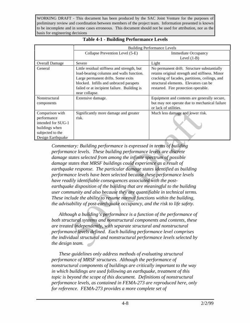
WORKING DRAFT - This document has been produced by the SAC Joint Venture for the purposes ofpreliminary review and coordination between members of the project team. Information presented is knownto be incomplete and in some cases erroneous. This document should not be used for attribution, nor as thebasis for engineering decisions
4-8 2/2/99
Table 4-1 - Building Performance Levels
Building Performance LevelsCollapse Prevention Level (5-E) Immediate Occupancy
Level (1-B)Overall Damage Severe LightGeneral Little residual stiffness and strength, but
load-bearing columns and walls function.Large permanent drifts. Some exitsblocked. Infills and unbraced parapetsfailed or at incipient failure. Building isnear collapse.
No permanent drift. Structure substantiallyretains original strength and stiffness. Minorcracking of facades, partitions, ceilings, andstructural elements. Elevators can berestarted. Fire protection operable.
Nonstructuralcomponents
Extensive damage. Equipment and contents are generally secure,but may not operate due to mechanical failureor lack of utilities.
Comparison withperformanceintended for SUG-1buildings whensubjected to theDesign Earthquake
Significantly more damage and greaterrisk.
Much less damage and lower risk.
Commentary: Building performance is expressed in terms of buildingperformance levels. These building performance levels are discretedamage states selected from among the infinite spectrum of possibledamage states that MRSF buildings could experience as a result ofearthquake response. The particular damage states identified as buildingperformance levels have been selected because these performance levelshave readily identifiable consequences associated with the post-earthquake disposition of the building that are meaningful to the buildinguser community and also because they are quantifiable in technical terms.These include the ability to resume normal functions within the building,the advisability of post-earthquake occupancy, and the risk to life safety.
Although a building’s performance is a function of the performance ofboth structural systems and nonstructural components and contents, theseare treated independently, with separate structural and nonstructuralperformance levels defined. Each building performance level comprisesthe individual structural and nonstructural performance levels selected bythe design team.
These guidelines only address methods of evaluating structuralperformance of MRSF structures. Although the performance ofnonstructural components of buildings are critically important to the wayin which buildings are used following an earthquake, treatment of thistopic is beyond the scope of this document. Definitions of nonstructuralperformance levels, as contained in FEMA-273 are reproduced here, onlyfor reference. FEMA-273 provides a more complete set of

WORKING DRAFT - This document has been produced by the SAC Joint Venture for the purposes ofpreliminary review and coordination between members of the project team. Information presented is knownto be incomplete and in some cases erroneous. This document should not be used for attribution, nor as thebasis for engineering decisions
4-9 2/2/99
recommendations with regard to evaluating the performance ofnonstructural components.
4.2.2.1 Structural Performance Levels
Two discrete structural performance levels are defined in these guidelines.Acceptance criteria, which relate to the permissible earthquake-induced forces anddeformations for the various elements of MRSF structures, are tied directly to thestructural performance levels. The performance levels are discrete damage states forwhich specific acceptance criteria are defined.
Structural Performance Levels are the Incipient Damage Level (S-1), and the CollapsePrevent Level (S-5). Table 4-2 relates these structural performance levels to the limitingdamage states for common vertical elements of MRSF structures. Later sections of theseGuidelines specify design parameters (inter-story drift ratios and component capacities)recommended as limiting values for calculated structural deformations and stresses fordifferent structural components, in order to attain these structural performance levels for aknown earthquake demand.
Table 4-2 - Structural Performance Levels
Structural Performance LevelsElements Type Collapse Prevention S-5 Incipient Damage S-1Girder Extensive distortion. A few girders
may experience fractureMinor local yielding at a fewplaces.
Column Moderate distortion; some columnsexperience yielding. Some localbuckling of flanges
No observable damage ordistortion
Connection Many fractures (X% of total ?)and/or extensive yielding
No observable fractures; minoryielding at some connections
Panel Zone Extensive distortion Minor distortionColumn Splice Ductile
SplicesFractures at some locations No yielding
Base Plate Extensive yielding of anchor boltsand base plate
No observable damage ordistortion
Drift Inter-story 3%-6% depending on structuralsystem
1% - 1-1/2% transientnegligible permanent

WORKING DRAFT - This document has been produced by the SAC Joint Venture for the purposes ofpreliminary review and coordination between members of the project team. Information presented is knownto be incomplete and in some cases erroneous. This document should not be used for attribution, nor as thebasis for engineering decisions
4-10 2/2/99
4.2.2.1.1 Incipient Damage Performance Level (S-1)
Structural Performance Level S-1, Incipient Damage, means the post-earthquakedamage state in which only very limited structural damage has occurred. The basicvertical and lateral force-resisting systems of the building retain nearly all of their pre-earthquake strength and stiffness. The risk of life-threatening injury as a result ofstructural damage is very low, and although some minor structural repairs may beappropriate, these would generally not be required prior to re-occupancy.
4.2.2.1.2 Collapse Prevent Performance Level (S-5)
Structural Performance Level S-5, Collapse Prevention, is that performance level inwhich the structure is on the verge of experiencing partial or total collapse. Substantialdamage to the structure has occurred, potentially including significant degradation in thestiffness and strength of the lateral force-resisting system, large permanent lateraldeformation of the structure, and to a more limited extent, degradation in the verticalload-carrying capacity. However, all significant components of the gravity load-resistingsystem must continue to carry their gravity load demands. Significant risk of injury dueto falling hazards from structural debris may exist. The structure may not be technicallypractical to repair and is not safe for re-occupancy, aftershock activity could crediblyinduce collapse.
Commentary: When a building is subjected to earthquake ground motion,a pattern of lateral deformations that varies with time is induced into thestructure. At any given point in time, a particular state of lateraldeformation will exist in the structure, and as some time within the periodin which the structure is responding to the ground motion, a maximumpattern of deformation will occur. At relatively low levels of groundmotion, the deformations induced within the building will be limited, andthe resulting stresses which develop within the structural components willbe within the elastic range of behavior. Within this elastic range, thestructure will experience no damage. All structural components willretain their original strength, stiffness and appearance, and when theground motion stops, the structure will return to its pre-earthquakecondition.
At more severe levels of ground motion, the lateral deformationsinduced into the structure will be larger. As these deformations increase,so will demands on the individual structural components. At differentlevels of deformation, corresponding to different levels of ground motionseverity, individual components of the structure will be strained beyondtheir elastic range. As this occurs, the structure starts to experiencedamage in the form of buckling, yielding and fracturing of the variouscomponents. As components become damaged, they degrade in stiffness,

WORKING DRAFT - This document has been produced by the SAC Joint Venture for the purposes ofpreliminary review and coordination between members of the project team. Information presented is knownto be incomplete and in some cases erroneous. This document should not be used for attribution, nor as thebasis for engineering decisions
4-11 2/2/99
and some elements will begin to lose their strength. In general, when astructure has responded to ground motion within this range of behavior, itwill not return to its pre-earthquake condition when the ground motionstops. Some permanent deformation may remain within the structure anddamage will be evident throughout. Depending on how far the structurehas been deformed, and in what pattern, the structure may have lost asignificant amount of its original stiffness and, possibly, strength.
Brittle elements are not able to sustain inelastic deformations and willfail suddenly; the consequences may range from local and repairabledamage to collapse of the of the structural system. At higher levels ofground motion, the lateral deformations induced into the structure willstrain a number of elements to a point at which the elements behave in abrittle manner, or as a result of the decreased overall stiffness, thestructure loses stability. Eventually, partial or total collapse of thestructure can occur. The structural performance levels relate the extent ofa building’s response to earthquake hazards to these various possibledamage states.
At the Incipient Damage Level, damage is relatively limited. Thestructure retains a significant portion of its original stiffness and most ifnot all of its strength. At the Collapse Prevention level, the building hasexperienced extreme damage. If laterally deformed beyond this point, thestructure can experience instability and collapse. FEMA-273 alsoincludes consideration of a Life Safety level, intermediate between thedamage states represented by Incipient Damage and Collapse Prevention.The Life Safety level is defined in FEMA-273 as occurring at 75% of thelateral displacement at which Collapse Prevention occurs. Given thiscircular definition of the Life Safety level, and the fact that the NEHRPProvisions have moved towards designing for Collapse Prevention, asopposed to Life Safety performance, this performance level has beenomitted from these guidelines.
4.2.2.2 Nonstructural Performance Levels
Nonstructural Performance Levels are defined in these Guidelines for reference only.No specific guidelines are provided for attaining these performance levels. Refer toFEMA-273 for more detailed information on the performance design of nonstructuralcomponents and systems.
4.2.2.2.1 Operational Performance Level (N-A)
Nonstructural Performance Level A, Operational, means the post-earthquake damagestate of the building in which the nonstructural components are able to support thebuilding’s intended function. Under this level, most nonstructural systems required for

WORKING DRAFT - This document has been produced by the SAC Joint Venture for the purposes ofpreliminary review and coordination between members of the project team. Information presented is knownto be incomplete and in some cases erroneous. This document should not be used for attribution, nor as thebasis for engineering decisions
4-12 2/2/99
normal use of the building including lighting, plumbing, HVAC, computer systems arefunctional although minor cleanup and repair of some items may be required. Thisperformance level requires considerations beyond those that are normally within the soleprovince of the structural engineer. In addition to assuring that nonstructural componentsare properly mounted and braced within the structure, in order to achieve thisperformance, it is often necessary to provide emergency standby utilities. It may also benecessary to performance rigorous qualification testing of the ability of key electrical andmechanical equipment items to function during or after strong shaking.
4.2.2.2.2 Immediate Occupancy Level (N-B)
Nonstructural Performance Level B, Immediate Occupancy, means the post-earthquake damage state in which only limited nonstructural damage has occurred. Basicaccess and life safety systems, including doors, stairways, elevators, emergency lighting,fire alarms, and suppression systems, remain operable, provided that power is available.There could be minor window breakage and slight damage to some components.Presuming that the building is structurally safe, it is expected that occupants could safelyremain in the building, although normal use may be impaired and some cleanup andinspection may be required. In general, components of mechanical and electrical systemsin the building are structurally secured and should be able to function if necessary utilityservice is available. However, some components may experience misalignments orinternal damage and be inoperable. Power, water, natural gas, communications lines, andother utilities required for normal building use may not be available. The risk of life-threatening injury due to nonstructural damage is very low.
4.2.2.2.3 Life Safety Level (N-C)
Nonstructural Performance Level C, Life Safety, is the post-earthquake damage statein which potentially significant and costly damage has occurred to nonstructuralcomponents but they have not become dislodged and fallen, threatening life safety eitherwithin or outside the building. Egress routes within the building are not extensivelyblocked, but may be impaired by lightweight debris. HVAC, plumbing, and firesuppression systems may have been damaged, resulting in local flooding as well as lossof function. While injuries may occur during the earthquake from the failure ofnonstructural components, it is expected that overall, the risk of life-threatening injury isvery low. Restoration of the nonstructural components may take extensive effort.
4.2.2.2.4 Hazards Reduced Level (N-D)
Nonstructural Performance Range D, Hazards Reduced, represents a post-earthquakedamage state range in which extensive damage has occurred to nonstructural components,but large or heavy items that pose a falling hazard to a number of people such as parapets,cladding panels, heavy plaster ceilings, or storage racks are prevented from falling.While isolated serious injury could occur from falling debris, failures that could injurelarge numbers of persons, either inside or outside the structure, should be avoided. Exits,
WORKING DRAFT - This document has been produced by the SAC Joint Venture for the purposes ofpreliminary review and coordination between members of the project team. Information presented is knownto be incomplete and in some cases erroneous. This document should not be used for attribution, nor as thebasis for engineering decisions
4-13 2/2/99
fire suppression systems, and similar life-safety issues are not addressed in thisperformance level.
4.3 Evaluation Approach
Performance evaluation of MRSF structures can be initiated only after a preliminarydesign, conforming to the building code provisions, has been prepared. The basicapproach is to develop a mathematical model of the structure and to evaluate its responseto the earthquake hazards by one or more methods of structural analysis. The structuralanalysis is used to predict the value of various structural response parameters. Theseinclude:
• Inter-story drift
• Axial forces, moments and shears on individual elements
These structural response parameters are related to the amount of damage experienced byindividual structural components as well as the structure as a whole. For eachperformance level, these guidelines specify acceptance criteria for each of the designparameters indicated above. Acceptance criteria are limiting values for the various designparameters, at which damage corresponding to the specific performance level has asignificant probability of exceedance. Acceptability of structural performance isevaluated considering both local (element level) performance and global performance.Acceptance criteria have been developed on a reliability basis, incorporating load andresistance factors related to the uncertainty inherent in the evaluation process, such that aconfidence level can be established with regard to the ability of a structure to actuallyprovide specific performance at selected probability of exceedance.
Once an analysis is performed, predicted demands are factored by load factors, λ, toaccount for the uncertainty inherent in their computation, as well as variability instructural response, and compared against acceptance criteria, which have also beenfactored, by resistance factors, φ, to account for uncertainties and variation inherent instructural capacity. If the factored demands are less than the factored acceptance criteria(capacities), then the structure is indicated to be capable of meeting the desiredperformance, with at least a mean level of confidence. If the factored demands exceedthe factored acceptance criteria, then there is less than a mean level of confidence that thepredicted performance will be attained for the specified exceedance probability.Procedures are provided to permit calculation of the level of confidence provided by adesign, with regard to specific performance objectives, based on the ratio of factoredcapacity to factored demand. If the predicted level of confidence is inadequate, then thedesign must be revised and the performance evaluation process repeated. An iterativeapproach consisting of trial designs, followed by verification analyses, evaluation ofdesign parameters against acceptance criteria, and calculation of confidence level isrepeated until an acceptable design solution is found.

WORKING DRAFT - This document has been produced by the SAC Joint Venture for the purposes ofpreliminary review and coordination between members of the project team. Information presented is knownto be incomplete and in some cases erroneous. This document should not be used for attribution, nor as thebasis for engineering decisions
4-14 2/2/99
Commentary: These guidelines adopt a load and resistance factor design(LRFD) model for performance evaluation. The purpose of this LRFDapproach is to develop estimates of the confidence level inherent in adesign with regard to a specific performance objective (probability ofexceeding a specified performance level, within a 50 year period).
The basic process starts with the selection of a performance objective.This consists of the specification of a performance level and a desiredprobability of exceedance for this performance level in a 50 year period(PE50). Once this probability of exceedance is selected, two hazardparameters are determined, from the site hazard curve. These are thevalue of spectral response acceleration Sa at the fundamental period of thestructure for the selected hazard level (PE50) and the slope of the hazardcurve, k, in logarithmic coordinates, evaluated at the PE50.
Using the Sa value appropriate to the hazard probability, a structuralanalysis is performed to determine the maximum inter-story drift demandfor the structure. This is factored by a load factor, λ, to account for theuncertainty and variation inherent in the analytical process related toinaccuracies inherent in the analytical approach, the modeling of thestructure, and the estimation of the ground motion itself. The load factorλ, is calculated as:
λ βσ
=∑
e
k
b i22
(4-1)
where β is a bias factor, that accounts for under or over-prediction ofinter-story drift inherent in a particular analytical procedure, k is theslope of the hazard curve, evaluated in log-log coordinates, b is aregression coefficient that relates variation in inter-story drift to hazard,and which may typically be taken as unity, and Σσi
2 is the sum of thestandard deviations of the logarithmic distribution of inter-story driftpredictions relative to the various random and uncertain parameters.Tabulated values of these λ factors are provided in these guidelines forvarious analytical procedures and typical framing conditions.
The factored demand, calculated from the analysis represents a meanestimate of the probable maximum inter-story drift demand. Theseguidelines also tabulate permissible inter-story drifts for the variousperformance levels, dependent on frame and connection configuration, aswell as capacity factors, that similarly adjust the estimated capacity of thestructure to a mean value. Guidelines are provided in Chapter 3 for

WORKING DRAFT - This document has been produced by the SAC Joint Venture for the purposes ofpreliminary review and coordination between members of the project team. Information presented is knownto be incomplete and in some cases erroneous. This document should not be used for attribution, nor as thebasis for engineering decisions
4-15 2/2/99
determination of φ factors for connections for which project specificqualification testing is performed.
Once the factored demand and capacities are determined, aparameter, γcon is calculated from the equation:
γφλcon
C
D
=∆∆
(4-2)
The value of γcon is then used directly to determine an associatedconfidence level for the desired performance, based on tabulated valuesrelated to both the slope of the hazard curve and also the uncertaintyinherent in the estimation of the building’s demand and capacities. Valuesof γcon exceeding 1.0 indicate greater than mean confidence of achievingthe desired performance. Values less than 1.0 indicate less than meanconfidence.
4.4 Analysis
In order to evaluate the performance of an MRSF structure it is necessary to constructa mathematical model of the structure that represents its strength and deformationcharacteristics and to conduct an analysis to predict the values of various designparameters when it is subjected to design ground motion. This section providesguidelines for selecting an appropriate analysis procedure and for modeling. Generalrequirements for the mathematical model are presented in Section 2.7.
4.4.1 Alternative Procedures
Four alternative analytical procedures are available for use in performance evaluationof MRSF structures. The basic analytical procedures are described in detail in FEMA-273. This section provides supplementary guidelines on the applicability of the FEMA-273 procedures and also provides supplemental modeling recommendations. The fourprocedures are:
• Linear static procedure - an equivalent lateral force technique, similar, butnot identical to that contained in many model building code provisions
• Linear dynamic procedure - an elastic, modal response spectrum analysisor an elastic time history analysis
• Nonlinear static procedure - a simplified nonlinear analysis procedure inwhich the forces and deformations induced by a monotonically increased patternof lateral loading is evaluated using a series of incremental elastic analyses of

WORKING DRAFT - This document has been produced by the SAC Joint Venture for the purposes ofpreliminary review and coordination between members of the project team. Information presented is knownto be incomplete and in some cases erroneous. This document should not be used for attribution, nor as thebasis for engineering decisions
4-16 2/2/99
structural models that are sequentially degraded to represent the effects ofstructural non-linearity.
• Nonlinear dynamic procedure - a nonlinear dynamic analysis procedure inwhich the response of a structure to a ground motion history is determinedthrough numerical integration of the equations of motion for the structure.Structural stiffness is altered during the analysis to conform to nonlinearhysteretic models of the structural components. Table ( ) contains hystereticmodels for different types of beam-column connections and other modelingparameters for nonlinear dynamic analyses (distributed plasticity models, pointhinge models, bilinear nondegrading and degrading, cyclic stress-strain models,post-fracture models, panel zone, etc.).
Commentary: The purpose of structural analyses performed as part of theperformance evaluation process is to predict the values of key responseparameters, that are indicative of the structure’s performance, when it issubjected to a design ground motion. Once the values of these responseparameters are predicted, the structure is evaluated for adequacy usingthe basic equation:
γφλcon
C
D
=∆∆
(4-3)
where:
λ = a load factor to account for uncertainty in the prediction ofdemands (the value of the response parameters)
∆D = the predicted inter-story drift demandφ = a capacity reduction factor to account for uncertainty in the
capacity of the structure∆C= the capacity for the design parameter (acceptance criteria)
γcon = an index parameter by which confidence in performance predictioncan be related
Analyses performed in support of design, as required by the codeprovisions, evaluate the strength and deformation of the structure when itis subjected to a somewhat arbitrary level of loading. The code loadinglevel is based on, but substantially reduced from, the response predictedby an elastic analysis of the structure’s dynamic response to the expectedground motions, which have been reduced by a factor, R, to approximatelyaccount for the beneficial effects of inelastic response.
Analyses conducted in support of performance evaluation, under theseguidelines, take a markedly different approach. Rather than evaluating

WORKING DRAFT - This document has been produced by the SAC Joint Venture for the purposes ofpreliminary review and coordination between members of the project team. Information presented is knownto be incomplete and in some cases erroneous. This document should not be used for attribution, nor as thebasis for engineering decisions
4-17 2/2/99
the forces and deformations induced in the structure under arbitrarilyreduced loading levels, these analysis procedures attempt to predict,within probabilistically defined bounds, the actual values of the importantresponse parameters under the design ground motion.
The ability of the performance evaluation to reliably estimate theprobable performance of the structure is dependent on the ability of theanalysis procedure to predict the values of these response parameterswithin acceptable levels of confidence. The linear dynamic procedure isable to provide relatively reliable estimates of the response parameters forstructures that exhibit elastic, or near elastic behavior. The linear staticprocedure inherently has more uncertainty associated with its estimates ofthe response parameters because it less accurately accounts for thedynamic characteristics of the structure. The nonlinear static procedureis more reliable than the linear procedures in predicting responseparameters for structures that exhibit significant nonlinear behavior,particularly if they are irregular. However, it does not accurately accountfor the effects of higher mode response and therefore, when used forstructures in which higher mode response is significant, must also beaccompanied by a linear dynamic analysis. If appropriate modeling isperformed, the nonlinear dynamic approach is most capable of capturingthe probable behavior of the real structure in response to ground motion,however, there are considerable uncertainties associated even with thevalues of the response parameters predicted by this technique. Uniqueload factors, λ, are specified for each of the analysis methods, and severalalternative modeling approaches, depending on the performance levels, toaccount for these uncertainties.
4.4.2 Procedure Selection
Table 4-3 indicates the recommended analysis procedures for various performancelevels and conditions of structural regularity. Also indicated in the table are the loadfactors, λ, associated with each.

WORKING DRAFT - This document has been produced by the SAC Joint Venture for the purposes ofpreliminary review and coordination between members of the project team. Information presented is knownto be incomplete and in some cases erroneous. This document should not be used for attribution, nor as thebasis for engineering decisions
4-18 2/2/99
Table 4-3 Analysis Procedure Selection Criteria
Performance Analysis ProcedureLevel Linear Static Linear Dynamic Nonlinear Static Nonlinear
DynamicIncipient DamageS-1
Permitted forregular structures,per the NEHRPProvisionsλ = 1.3
Permitted forstructures of anyconfigurationλ = 1.0
Permitted forstructures of anyconfigurationλ = 1.2
Permitted forstructures of anyconfigurationλ = 1.0
CollapsePrevention S-5
Permitted forregular structures,as indicated inFEMA-273λ = 2.0
Permitted forregular structures,as indicated inFEMA-273λ = 1.5
Permitted forregular or irregularstructures, withperiods less than1.0 second and asindicated inFEMA-273λ = 1.2
Permitted for allstructures, asindicated inFEMA-273λ = 1.0
4.4.3 Linear Static Procedure (LSP)
4.4.3.1 Basis of the Procedure
Linear static procedure analysis of MRSF structures shall be conducted in accordancewith the Guidelines of FEMA-273, except as specifically noted herein. In this procedure,a total lateral force is applied to the structure, and deflections and component forces underthis applied loading is determined.
Results of the LSP are to be checked using the applicable acceptance criteria ofSection 4.5. Calculated internal forces typically will exceed those that the building candevelop, because of anticipated inelastic response of components and elements. Theseobtained design forces are evaluated through the acceptance criteria of Section 4.5.
Commentary: The linear static procedure is a method of estimating theresponse of the structure to earthquake ground shaking by representingthe effects of this response through the application of a series of staticlateral forces applied to an elastic mathematical model of the building’sstiffness. The forces are applied to the structure in a pattern thatrepresents the typical distribution of inertial forces in a regular structureresponding in a linear manner to the ground shaking excitation, factoredto account in an approximate manner, for the probable inelastic behaviorof the structure. It is assumed that the structure’s response is dominatedby the fundamental mode and that the lateral drifts induced in the elasticstructural model by these forces represent a reasonable estimate of theactual deformation of the structure when responding inelastically.
In the LSP, the building is modeled with linearly-elastic stiffness and
WORKING DRAFT - This document has been produced by the SAC Joint Venture for the purposes ofpreliminary review and coordination between members of the project team. Information presented is knownto be incomplete and in some cases erroneous. This document should not be used for attribution, nor as thebasis for engineering decisions
4-19 2/2/99
equivalent viscous damping that approximate values expected for loadingto near the yield point. Earthquake demands for the LSP are representedby the static lateral forces whose sum is equal to the pseudo lateral load.The magnitude of the pseudo lateral load has been selected with theintention that when it is applied to the linearly elastic model of thebuilding it will result in design displacement amplitudes approximatingmaximum displacements that are expected during the design earthquake.If the building responds essentially elastically to the design earthquake,the calculated internal forces will be reasonable approximations of thoseexpected during the design earthquake. If the building respondsinelastically to the design earthquake, as will commonly be the case, theinternal forces that would develop in the yielding building will be lessthan the internal forces calculated on an elastic basis.
The performance of MRSF structures is most closely related to totalinelastic deformation demands on the various elements that comprise thestructure, such as plastic rotation demands on beam-column assembliesand tensile demands on column splices. Linear analysis methods do notpermit direct evaluation of such demands. However, through a series ofanalytical evaluations of typical buildings for a number of earthquakerecords, it has been possible to develop statistical correlation between theinter-story drift demands predicted by a linear analysis and the actualinelastic deformation demands determined by more accurate nonlinearmethods. These correlation relationships are reasonably valid for regularstructures, using the definitions of regularity contained in the buildingcode. Thus, the performance evaluation process using LSP proceduresconsists of performing the LSP analysis, to determine an estimate of inter-story drift demands, adjustment of these demands with the load factor, λ,and comparison with tabulated inter-story drift capacities.
Although performance of MRSF structures is closely related to inter-story drift demand, there are some failure mechanisms, notably, failure ofcolumn splices, that are more closely related to strength demand.However, since inelastic structural behavior affects the strength demandon such elements, linear analysis is not capable of directly predictingthese demands, either, except when the structural response is essentiallyelastic. Therefore, as with inter-story drift demand, correlationcoefficients have been developed that allow approximate estimation of thestrength demands on such elements by adjusting demands calculated fromthe linear analysis.
Two basic assumptions apply in this evaluation approach. First - thatthe distribution of deformations predicted by an elastic analysis is similarto that which will occur in actual non-linear response; Second - that the

WORKING DRAFT - This document has been produced by the SAC Joint Venture for the purposes ofpreliminary review and coordination between members of the project team. Information presented is knownto be incomplete and in some cases erroneous. This document should not be used for attribution, nor as thebasis for engineering decisions
4-20 2/2/99
ratio of computed strength demands from an elastic analysis to yieldcapacities is a relative indication of the inelastic ductility demand on theelement. These assumptions are never particularly accurate but becomequite inaccurate for structures that are highly irregular and experiencelarge inelastic demands.
4.4.3.2 Modeling and Analysis Considerations.
Period Determination. A fundamental period shall be calculated for each of twoorthogonal directions of building response, by one of the following three methods.
Method 1. Eigenvalue (dynamic) analysis of the mathematical model of the building.The model for buildings with flexible diaphragms shall consider representation ofdiaphragm flexibility unless it can be shown that the effects of omission will not besignificant.
Method 2: Evaluation of the following equation:
T C ht n= 3 4/ (4-4)
where
T = Fundamental period (in seconds) in the direction under consideration
Ct =0.035 for moment-resisting frame systems of steel
hn = Height (in feet) above the base to the roof level
Method 3. The fundamental period of a one-story building with a single span flexiblediaphragm may be calculated as:
T w d= +( . . ) .01 0 078 0 5∆ ∆ (4-5)
where ∆w and ∆d are in-plane frame and diaphragm displacements in inches, due to alateral load, in the direction under consideration, equal to the weight tributary to thediaphragm. For multiple-span diaphragms, a lateral load equal to the gravity weighttributary to the diaphragm span under consideration should be applied to each diaphragmspan to calculate a separate period for each diaphragm span. The period so calculated thatmaximizes the pseudo lateral load shall be used for design of all walls and diaphragmspans in the building.
4.4.3.3 Determination of Actions and Deformations
4.4.3.3.1 Pseudo Lateral Load

WORKING DRAFT - This document has been produced by the SAC Joint Venture for the purposes ofpreliminary review and coordination between members of the project team. Information presented is knownto be incomplete and in some cases erroneous. This document should not be used for attribution, nor as thebasis for engineering decisions
4-21 2/2/99
A pseudo lateral load, given by equation 4-6, shall be independently calculated foreach of two orthogonal directions of building response, and applied to a mathematicalmodel of the building structure.
V C C C S Wa= 1 2 3 (4-6)
where:
C1 = Modification factor to relate expected maximum inelastic displacements todisplacements calculated for linear elastic response. C1 may be calculatedusing the procedure indicated in Section 3.3.3.3 in FEMA 273 with theelastic base shear capacity substituted for Vy. Alternatively, C1 may betaken from Table 4.4
Linear interpolation shall be used to calculate C1 for intermediate values ofT.
T = Fundamental period of the building in the direction under consideration. Ifsoil-structure interaction is considered, the effective fundamental period Tshall be substituted for T.
T0 = Characteristic period of the response spectrum, defined as the periodassociated with the transition from the constant acceleration segment ofthe spectrum to the constant velocity segment of the spectrum.
C2 = Modification factor to represent the effect of stiffness degradation andstrength deterioration on maximum displacement response. Values of C2
for different framing systems and Performance Levels are listed in Table4-4. Linear interpolation shall be used to estimate values for C2 forintermediate values of T.
C3 = Modification factor to represent increased displacements due to dynamicP=∆ effects. This effect is in addition to the consideration of static P-∆effects as defined in Section 2.7. C3 shall be calculated as 1 + 5 (θ-0.1)/T.The maximum value θ for all stories in the building shall be used tocalculate C3. Alternatively, the values of C3 in Table 4-4 may be used.
θ =P
VH
∆(4-7)
Sa = Response spectrum acceleration, at the fundamental period and dampingratio of the building in the direction under consideration.
W = Total dead load and anticipated live load as indicated below:
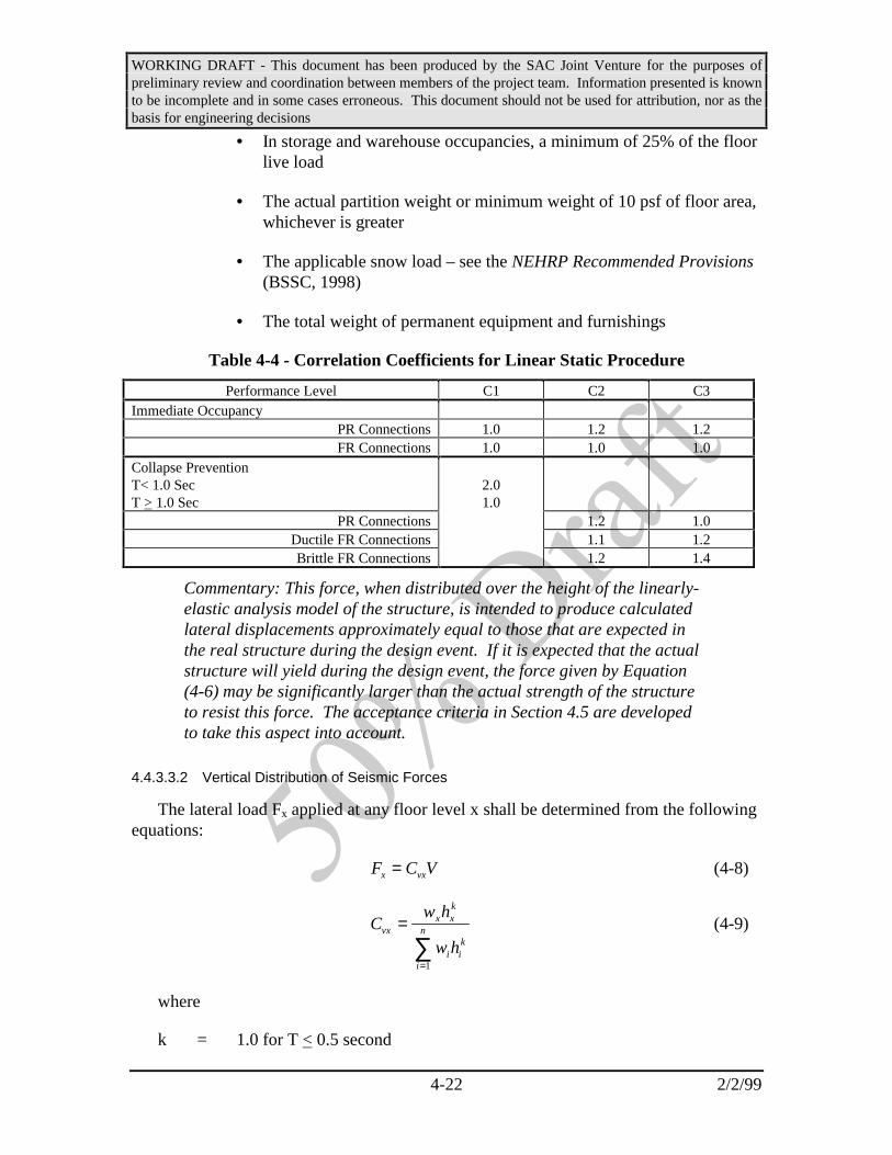
WORKING DRAFT - This document has been produced by the SAC Joint Venture for the purposes ofpreliminary review and coordination between members of the project team. Information presented is knownto be incomplete and in some cases erroneous. This document should not be used for attribution, nor as thebasis for engineering decisions
4-22 2/2/99
• In storage and warehouse occupancies, a minimum of 25% of the floorlive load
• The actual partition weight or minimum weight of 10 psf of floor area,whichever is greater
• The applicable snow load – see the NEHRP Recommended Provisions(BSSC, 1998)
• The total weight of permanent equipment and furnishings
Table 4-4 - Correlation Coefficients for Linear Static Procedure
Performance Level C1 C2 C3Immediate Occupancy
PR Connections 1.0 1.2 1.2FR Connections 1.0 1.0 1.0
Collapse PreventionT< 1.0 SecT > 1.0 Sec
2.01.0
PR Connections 1.2 1.0Ductile FR Connections 1.1 1.2Brittle FR Connections 1.2 1.4
Commentary: This force, when distributed over the height of the linearly-elastic analysis model of the structure, is intended to produce calculatedlateral displacements approximately equal to those that are expected inthe real structure during the design event. If it is expected that the actualstructure will yield during the design event, the force given by Equation(4-6) may be significantly larger than the actual strength of the structureto resist this force. The acceptance criteria in Section 4.5 are developedto take this aspect into account.
4.4.3.3.2 Vertical Distribution of Seismic Forces
The lateral load Fx applied at any floor level x shall be determined from the followingequations:
F C Vx vx= (4-8)
Cw h
w hvx
x xk
i ik
i
n=
=∑
1
(4-9)
where
k = 1.0 for T < 0.5 second

WORKING DRAFT - This document has been produced by the SAC Joint Venture for the purposes ofpreliminary review and coordination between members of the project team. Information presented is knownto be incomplete and in some cases erroneous. This document should not be used for attribution, nor as thebasis for engineering decisions
4-23 2/2/99
= 2.0 for T > 2.5 seconds
Linear interpolation shall be used to estimate values of k for the intermediatevalues of T.
Cvx = Vertical distribution factor
V = Pseudo lateral load from Equation (4-6)
wi = Portion of the total weight W located on or assigned to floor level i
wx = Portion of the total building weight W located on or assigned to floor level x
hi = Height (in ft) from the base to floor level i
hx = Height (in ft) from the base to floor level x
4.4.3.3.3 Horizontal Distribution of Seismic Forces
The seismic forces at each floor level of the building shall be distributed according tothe distribution of mass at that floor level.
4.4.3.3.4 Floor Diaphragms
The lateral seismic load on each flexible diaphragm shall be distributed along thespan of that diaphragm, considering its displaced shape.
4.4.3.3.5 Determination of Deformations
Structural deformations and story drifts shall be calculated using lateral loads inaccordance with Equations 4-6, and 4-8 and stiffnesses obtained from Chapter 2.Factored inter-story drift demands, λδi, at each story “i”, shall be determined by applyingthe appropriate load factor, λ, obtained from Table 4-2.
4.4.3.3.6 Determination of Column Demands
Columns and column splices shall be evaluated for factored axial demands, Pc’,obtained from the equation:
PP
C C Ccc’=
λ1 2 3
(4-10)
where: P is the axial load in the element computed from the analysisC1, C2, and C3 are the coefficients previously defined, andλc is obtained from Table 4-5

WORKING DRAFT - This document has been produced by the SAC Joint Venture for the purposes ofpreliminary review and coordination between members of the project team. Information presented is knownto be incomplete and in some cases erroneous. This document should not be used for attribution, nor as thebasis for engineering decisions
4-24 2/2/99
Table 4-5 Value of Load Factors λc for Columns - Linear Static Procedure
Column Located In MM p
1
< 1 1 < MM p
< 2 2 < MM p
Top 3 stories of building 1.25 15.
M M p
175.
M M p
10 stories below the top 3stories
1.25 125.
M M p
135.
M M p
All other 1.25 115.
M M p
125.
M M p
1. MM p
is the average of the ratio of beam moments calculated from the analysis to the plastic moment
capacities of the beams, for all beams framing into the column in stories above the level underconsideration.
4.4.4 Linear Dynamic Procedure (LDP)
4.4.4.1 Basis of the Procedure
Linear dynamic procedure analysis of MRSF structures shall be conducted inaccordance with the Guidelines of FEMA-273 except as specifically noted herein.Coefficients C1, C2, and C3 should be taken as indicated in Table 4-4.
Commentary: The linear dynamic procedure is similar in approach to the linearstatic procedure, described in the previous section. However, because it directlyaccounts for the stiffness and mass distribution of the structure in calculating thedynamic response characteristics, it is somewhat more accurate. Coefficients C1, C2, andC3, which account in an approximate manner for the differences between elasticpredictions of response and inelastic behavior are the same as for the linear staticmethod. Under the Linear Dynamic Procedure (LDP), inertial seismic forces, theirdistribution over the height of the building, and the corresponding internal forces andsystem displacements are determined using a linearly-elastic, dynamic analysis.
The basis, modeling approaches, and acceptance criteria of the LDP are similar tothose for the LSP. The main exception is that the response calculations are carried outusing either Modal Response Spectrum analysis (RSA) or Response-History Analysis(RHA). Modal spectral analysis is carried out using unreduced, linearly-elastic responsespectra scaled to the appropriate hazard level. As with the LSP, it is expected that the

WORKING DRAFT - This document has been produced by the SAC Joint Venture for the purposes ofpreliminary review and coordination between members of the project team. Information presented is knownto be incomplete and in some cases erroneous. This document should not be used for attribution, nor as thebasis for engineering decisions
4-25 2/2/99
LDP will produce estimates of displacements and inter-story drifts that are approximatelycorrect, but will produce estimates of internal forces that exceed those that would beobtained in a yielding building.
Estimates of inter-story drift and column axial demands shall be evaluated using theapplicable acceptance criteria of Section 4.5. Calculated displacements are factored bythe applicable load factor, λ, obtained from Table 4-3 and compared with factoredacceptable values, per Section 4.5. Calculated internal forces typically will exceed thosethat the building can sustain because of anticipated inelastic response of components andelements. These obtained design forces are evaluated through the acceptance criteria ofSection 4.5.
Commentary: Under the LDP, either a response spectrum or responsehistory analysis may be performed. Of these two approaches, responsespectrum analysis is both easier to perform and provides more reliableresults, and therefore, is the preferred approach under these guidelines.The results of response history analysis are highly dependent on thepeculiarities of the individual ground motion records used in the analysis.Every record ;results in spectra with large peaks and valleys. Dependingon the periods of the structure being analyzed, the structure may end upeither at a peak or a valley in a given record, and therefore, may give verydifferent predictions of structural response for multiple recordsrepresenting similar ground shaking events. For this reason, theseguidelines require that when response history analysis is used, a numberof analyses, using different records be performed and that responsequantities used for design be based on statistics obtained from thesemultiple analyses. The response spectrum analysis approach avoids thesecomplexities and when appropriate smoothed design spectra are utilized,provides valid design response quantities with less effort.
4.4.4.2 Modeling and Analysis Considerations
4.4.4.2.1 General
The LDP shall conform to the criteria of this section. The analysis shall be based onappropriate characterization of the ground motion. The modeling and analysisconsiderations set forth in Section 4.4.3.2 should apply to the LDP but alternativeconsiderations are presented below.
The LDP includes two analysis methods, namely, the Response Spectrum (RSA) andResponse-History Analysis (RHA) methods. The RSA uses peak modal responsescalculated from elastic dynamic analysis of a mathematical model. Only those modescontributing significantly to the response need to be considered. Modal responses arecombined using rational methods to estimate total building response quantities. RSHinvolves a time-step-by-time-step evaluation of building response, using discretized
WORKING DRAFT - This document has been produced by the SAC Joint Venture for the purposes ofpreliminary review and coordination between members of the project team. Information presented is knownto be incomplete and in some cases erroneous. This document should not be used for attribution, nor as thebasis for engineering decisions
4-26 2/2/99
recorded or synthetic earthquake records as base motion input. Requirements for the twoanalysis methods are outlined below.
4.4.4.2.2 Ground Motion Characterization
The horizontal ground motion should be characterized by one of the followingmethods:
• An elastic response spectrum, developed in accordance with the Guidelines ofFEMA-273 for the appropriate hazard return period
• Ground acceleration time histories that are compatible with such a responsespectrum, as indicated in FEMA-273
4.4.4.2.3 Response Spectrum Method
The requirement that all significant modes be included in the response analysis maybe satisfied by including sufficient modes to capture at least 90% of the participatingmass of the building in each of the building’s principal horizontal directions. Modaldamping ratios should reflect the damping inherent in the building at deformation levelsless than the yield deformation. Except for buildings incorporating passive or activeenergy dissipation devices, or base isolation technology, effective damping shall be takenas 5% of critical.
The peak member forces, displacements, story forces, story shears, and base reactionsfor each mode of response should be combined by recognized methods to estimate totalresponse. Modal combination by either the SRSS (square root sum of squares) rule or theCQC (complete quadratic combination) rule is acceptable.
Multidirectional excitation effects may be accounted for by combining 100% of theresponse due to loading in direction A with 30% of the response due to loading in thedirection B; and by combining 30% of the response in direction A with 100% of theresponse in direction B, where A and B are orthogonal directions of response for thebuilding.
4.4.4.2.4 Response-History Method
The requirements for the mathematical model for Response-History Analysis areidentical to those developed for Response Spectrum Analysis. The damping matrixassociated with the mathematical model should reflect the damping inherent in thebuilding at deformation levels less than the yield deformation.
Response-History Analysis should be performed using time histories preparedaccording to the guidelines of FEMA-273, using a minimum of three spectrumcompatible ground motions.

WORKING DRAFT - This document has been produced by the SAC Joint Venture for the purposes ofpreliminary review and coordination between members of the project team. Information presented is knownto be incomplete and in some cases erroneous. This document should not be used for attribution, nor as thebasis for engineering decisions
4-27 2/2/99
Response parameters should be calculated for each ground motion record. If threeResponse-History Analyses are performed, the maximum response of the parameter ofinterest should be used for design. If seven or more pairs of horizontal ground motionrecords are used for Response-History Analysis, the average response of the parameter ofinterest may be used for design.
Where three dimensional analyses are performed, multidirectional excitation effectsshould be accounted for by evaluating the response due to concurrent excitation to pairsof time histories. Where two dimensional analyses are performed, multidirectionalexcitation effects should be accounted for in the same manner as for RSA analysis.
4.4.4.3 Determination of Actions and Deformations
4.4.4.3.1 Factored Inter-story Drift Demand
Factored inter-story drift demand shall be obtained by multiplying the results of theRSA or RSH analysis by the product of the modification factors, C1, C2, and C3 definedin Section 4.4.3.2 and by the applicable λ obtained from Table 4-3.
4.4.4.3.2 Determination of Column Demands
Columns and column splices shall be evaluated for factored axial demands, Pc’,obtained from the equation:
PP
C C Ccc’=
λ1 2 3
(4-10)
where: P is the axial load in the element computed from the analysisC1, C2, and C3 are the coefficients previously defined, andλc is obtained from Table 4-6
Table 4-6 Value of Load Factors λc for Columns - Linear Dynamic Procedure
Column Located In MM p
1
< 1 1 < MM p
< 2 2 <MM p
Top 3 stories of building 1.0 125.
M M p
15.
M M p
10 stories below the top 3stories
1.0 115.
M M p
125.
M M p
WORKING DRAFT - This document has been produced by the SAC Joint Venture for the purposes ofpreliminary review and coordination between members of the project team. Information presented is knownto be incomplete and in some cases erroneous. This document should not be used for attribution, nor as thebasis for engineering decisions
4-28 2/2/99
All other 1.0 110.
M M p
115.
M M p
1. MM p
is the average of the ratio of beam moments calculated from the analysis to the plastic moment
capacities of the beams, for all beams framing into the column in stories above the level underconsideration.
4.4.5 Nonlinear Static Procedure (NSP)
4.4.5.1 Basis of the Procedure
Under the Nonlinear Static Procedure (NSP), a model directly incorporating theinelastic material and geometric response is displaced to a target displacement, andresulting internal deformations and forces are determined. The nonlinear load-deformation characteristics of individual components and elements of the building aremodeled directly. The mathematical model of the building is subjected to a pattern ofmonotonically increasing lateral forces or displacements until either a target displacementis exceeded or mathematical instability occurs. The target displacement is intended toapproximate the total maximum displacement likely to be experienced by the actualstructure, during the design earthquake. The target displacement may be calculated byany procedure that accounts for the effects of nonlinear response on displacementamplitude; one rational procedure is presented in Section 4.4.5.3. Because themathematical model accounts directly for effects of material and geometric inelasticresponse, the calculated internal forces will be reasonable approximations of thoseexpected during the design earthquake, presuming that an appropriate pattern of loadinghas been applied.
Results of the NSP are to be evaluated using the applicable acceptance criteria ofSection 4.5. Calculated inter-story drifts and column and column splice forces arefactored, and compared directly with factored acceptable values for the applicableperformance level.
Commentary: The nonlinear static analysis approach provides validresults only if response is dominated by the first mode behavior of thestructure. This is the basic reason that these guidelines recommend thisapproach be used only for structures with relatively short periods. Whatconstitutes a building with a “short period” is very much dependent on thespectral characteristics of ground shaking anticipated at the site. Thesmall magnitude events, that dominate the hazard at many central andeastern U.S. sites, tend to have most of their energy at very short periods,particularly on firm soil and rock sites. For sites subject to such shaking,nonlinear static analyses may be valid only for very short and rigidstructures.

WORKING DRAFT - This document has been produced by the SAC Joint Venture for the purposes ofpreliminary review and coordination between members of the project team. Information presented is knownto be incomplete and in some cases erroneous. This document should not be used for attribution, nor as thebasis for engineering decisions
4-29 2/2/99
4.4.5.2 Modeling and Analysis Considerations
4.4.5.2.1 General
In the context of these Guidelines, the NSP involves the monotonic application oflateral forces or displacements to a nonlinear mathematical model of a building until thedisplacement of the control node in the mathematical model exceeds a targetdisplacement. For buildings that are not symmetric about a plane perpendicular to theapplied lateral loads, the lateral loads must be applied in both the positive and negativedirections, and the maximum forces and deformations used for design.
The relation between base shear force and lateral displacement of the control nodeshall be established for control node displacements ranging between zero and 150% of thetarget displacement, δt, given by Equation 4-12. Performance evaluation shall be basedon those column forces and inter-story drifts corresponding to minimum horizontaldisplacement of the control node equal to the target displacement, δt.
Gravity loads shall be applied to appropriate elements and components of themathematical model during the NSP.
The analysis model shall be discretized in sufficient detail to represent adequately theload-deformation response of each component along its length. Particular attentionshould be paid to identifying locations of inelastic action along the length of acomponent, as well as at its ends.
4.4.5.2.2 Control Node
The NSP requires definition of the control node in a building. These Guidelinesconsider the control node to be the center of mass at the roof of a building; the top of apenthouse should not be considered as the roof. The displacement of the control node iscompared with the target displacement – a displacement that characterizes the effects ofearthquake shaking.
4.4.5.2.3 Lateral Load Patterns
Lateral loads should be applied to the building in profiles that approximately boundthe likely distribution of inertia forces in an earthquake. For three-dimensional analysis,the horizontal distribution should simulate the distribution of inertia forces in the plane ofeach floor diaphragm. For both two- and three-dimensional analysis, at least two verticaldistributions of lateral load should be considered. The first pattern, often termed theuniform pattern, should be based on lateral forces that are proportional to the total mass ateach floor level. The second pattern, termed the modal pattern in these Guidelines,should be selected from one of the following two options:

WORKING DRAFT - This document has been produced by the SAC Joint Venture for the purposes ofpreliminary review and coordination between members of the project team. Information presented is knownto be incomplete and in some cases erroneous. This document should not be used for attribution, nor as thebasis for engineering decisions
4-30 2/2/99
• a lateral load pattern represented by values of Cvx given in Equation 4-9, whichmay be used if more than 75% of the total mass participants in the fundamentalmode in the direction under consideration; or
• a lateral load pattern proportional to the story inertia forces consistent with thestory shear distribution calculated by combination of modal responses using (1)Response Spectrum Analysis of the building including a sufficient number ofmodes to capture 90% of the total mass, and (2) the appropriate ground motionspectrum.
4.4.5.2.4 Period Determination
The effective fundamental period Te in the direction under consideration shall becalculated using the force-displacement relationship of the NSP. The nonlinear relationbetween base shear and displacement of the target node should be replaced with a bilinearrelation to estimate the effective lateral stiffness, Ke, and the yield strength, Vy, of thebuilding. The effective lateral stiffness should be taken as the secant stiffness calculatedat a base shear force equal to 60% of the yield strength. The effective fundamental periodTe shall be calculated as:
T TK
Ke ii
e= (4-11)
where:
Ti = Elastic fundamental period (in seconds) in the direction under considerationcalculated by elastic dynamic analysis
Ki = Elastic lateral stiffness of the building in the direction under consideration
Ke = Effective lateral stiffness of the building in the direction under consideration
See Figure 4-1 for further information.
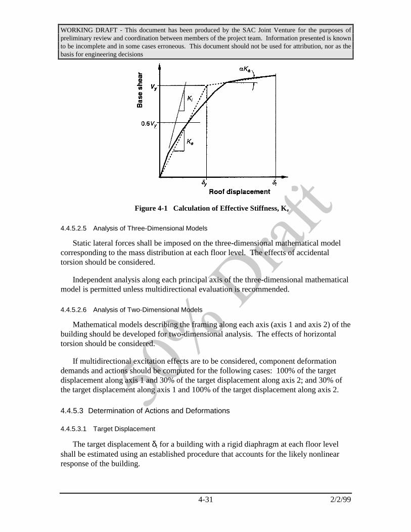
WORKING DRAFT - This document has been produced by the SAC Joint Venture for the purposes ofpreliminary review and coordination between members of the project team. Information presented is knownto be incomplete and in some cases erroneous. This document should not be used for attribution, nor as thebasis for engineering decisions
4-31 2/2/99
Figure 4-1 Calculation of Effective Stiffness, Ke
4.4.5.2.5 Analysis of Three-Dimensional Models
Static lateral forces shall be imposed on the three-dimensional mathematical modelcorresponding to the mass distribution at each floor level. The effects of accidentaltorsion should be considered.
Independent analysis along each principal axis of the three-dimensional mathematicalmodel is permitted unless multidirectional evaluation is recommended.
4.4.5.2.6 Analysis of Two-Dimensional Models
Mathematical models describing the framing along each axis (axis 1 and axis 2) of thebuilding should be developed for two-dimensional analysis. The effects of horizontaltorsion should be considered.
If multidirectional excitation effects are to be considered, component deformationdemands and actions should be computed for the following cases: 100% of the targetdisplacement along axis 1 and 30% of the target displacement along axis 2; and 30% ofthe target displacement along axis 1 and 100% of the target displacement along axis 2.
4.4.5.3 Determination of Actions and Deformations
4.4.5.3.1 Target Displacement
The target displacement δt for a building with a rigid diaphragm at each floor levelshall be estimated using an established procedure that accounts for the likely nonlinearresponse of the building.

WORKING DRAFT - This document has been produced by the SAC Joint Venture for the purposes ofpreliminary review and coordination between members of the project team. Information presented is knownto be incomplete and in some cases erroneous. This document should not be used for attribution, nor as thebasis for engineering decisions
4-32 2/2/99
One procedure for evaluating the target displacement is given by the followingequation:
δπt aeC C C C S
Tg= 0 1 2 3
2
24(4-12)
where:
Te = Effective fundamental period of the building in the direction underconsideration, sec
C0 = Modification factor to relate spectral displacement and likely building roofdisplacement.
Estimates for C0 can be calculated using one of the following:
• the first modal participation factor at the level of the control node
• the modal participation factor at the level of the control node calculatedusing a shape vector corresponding to the deflected shape of the buildingat the target displacement
• the appropriate value from Table 4-7
C1 = Modification factor to relate expected maximum inelastic displacement todisplacements calculated for linear elastic response
= 1.0 for Te > T0
= [1.0 + (R – 1)T0/Te]/R for Te < T0
Values for C1 need not exceed those values given in Section 4.4.3.3. In nocase may C1 be taken as less than 1.0.
T0 = Characteristic period of the response spectrum, defined as the periodassociated with the transition from the constant acceleration segment of thespectrum to the constant velocity segment of the spectrum.
R = Ratio of elastic strength demand to calculated yield strength coefficient. Seebelow for additional information.
C2 = Modification factor to represent the effect of hysteresis shape on themaximum displacement response. Values for C2 are established in Section4.4.3.3.

WORKING DRAFT - This document has been produced by the SAC Joint Venture for the purposes ofpreliminary review and coordination between members of the project team. Information presented is knownto be incomplete and in some cases erroneous. This document should not be used for attribution, nor as thebasis for engineering decisions
4-33 2/2/99
C3 = Modification factor to represent increased displacements due to dynamic P-∆ effects. For buildings with positive post-yield stiffness, C3 should be setequal to 1.0. For buildings with negative post-yield stiffness, values of C3
should be calculated using Equation 4-14. Values for C3 need not exceedthe values set forth in Section 4.4.3.3.
Sa = Response spectrum acceleration, at the effective fundamental period anddamping ratio of the building in the direction under consideration, g.
The strength ratio R should be calculated as:
RS
V W Ca
y= ⋅
/
1
0(4-13)
Table 4-7 Values for Modification Factor C0
Number of Stories Modification Factor1
1 1.02 1.23 1.35 1.4
10+ 1.5
1. Linear interpolation should be used to calculate intermediate values.
where Sa and C0 are as defined above, and:
Vy = Yield strength calculated using results of NSP, where the nonlinear force-displacement (i.e., base shear force versus control node displacement) curveof the building is characterized by a bilinear relation (Figure 4-1)
W = Total dead load and anticipated live load, as calculated in Section 4.4.3.3.
Coefficient C3 should be calculated as follows if the relation between base shear forceand control node displacement exhibits negative post-yield stiffness.
CR
Te3
3 2
101
= +−
.( ) /α
(4-14)
where R and Te are as defined above, and:
α = Ratio of post-yield stiffness to effective elastic stiffness, where the nonlinearforce-displacement relation is characterized by a bilinear relation (Figure 4-1)

WORKING DRAFT - This document has been produced by the SAC Joint Venture for the purposes ofpreliminary review and coordination between members of the project team. Information presented is knownto be incomplete and in some cases erroneous. This document should not be used for attribution, nor as thebasis for engineering decisions
4-34 2/2/99
For a building with flexible diaphragms at each floor level, a target displacementshould be estimated for each line of vertical seismic framing. The target displacementsshould be estimated using an established procedure that accounts for the likely nonlinearresponse of the seismic framing. One procedure for evaluating the target displacementfor an individual line of vertical seismic framing is given by Equation 4-12. Thefundamental period of each vertical line of seismic framing, for calculation of the targetdisplacement, should follow the general procedures described for the NSP; masses shouldbe assigned to each level of the mathematical model on the basis of tributary area.
For a building with neither rigid nor flexible diaphragms at each floor level, the targetdisplacement should be calculated using rational procedures. One acceptable procedurefor including the effects of diaphragm flexibility is to multiply the displacementcalculated using Equation 4-12 by the ratio of the maximum displacement at any point onthe roof and the displacement of the center of mass of the roof, both calculated by modalanalysis of a three-dimensional model of the building using the design response spectrum.The target displacement so calculated should be no less than that displacement given byEquation 4-12, assuming rigid diaphragms at each floor level. No vertical line of seismicframing should be evaluated for displacements smaller than the target displacement. Thetarget displacement should be modified according to Section 2.7 to account for systemtorsion.
4.4.5.3.2 Floor Diaphragms
The lateral seismic load on each flexible diaphragm shall be distributed along thespan of that diaphragm, considering its displaced shape.
4.4.5.3.3 Factored Inter-story Drift Demand
Factored inter-story drift demand shall be obtained by multiplying the maximuminter-story drift calculated at the target displacement by the applicable load factor λobtained from Table 4-3.
4.4.5.3.4 Factored Column and Column Splice Demands
Factored demands on columns and column splices shall be obtained by multiplyingthe calculated column forces at the target displacement by the applicable load factor λfrom Table 4-3.
4.4.6 Nonlinear Dynamic Procedure (NDP)
4.4.6.1 Basis of the Procedure
Under the Nonlinear Dynamic Procedure (NDP), inertial seismic forces, theirdistribution over the height of the building, and the corresponding internal forces and

WORKING DRAFT - This document has been produced by the SAC Joint Venture for the purposes ofpreliminary review and coordination between members of the project team. Information presented is knownto be incomplete and in some cases erroneous. This document should not be used for attribution, nor as thebasis for engineering decisions
4-35 2/2/99
system displacements are determined using an inelastic response history dynamicanalysis.
The basis, modeling approaches, and acceptance criteria for the NDP are similar tothose for the NSP. The main exception is that the response calculations are carried outusing Response-History Analysis. With the NDP, the design displacements are notestablished using a target displacement, but instead are determined directly throughdynamic analysis using ground motion records. Calculated response can be highlysensitive to characteristics of individual ground motions; therefore, it is necessary to carryout the analysis with more than one ground motion record. Because the numerical modelaccounts directly for effects of material and geometric inelastic response, the calculatedinternal forces will be reasonable approximations of those expected during the designearthquake.
Results of the NDP are to be checked using the applicable acceptance criteria ofSection 4.5. Calculated displacements and internal forces are factored, and compareddirectly with factored acceptable values for the applicable performance level.
4.4.6.2 Modeling and Analysis Assumptions
4.4.6.2.1 General
The NDP shall conform to the criteria of this section. The analysis shall be based oncharacterization of the seismic hazard in the form of ground motion records, compatiblewith a spectrum that has been scaled to the appropriate level of hazard. The modelingand analysis considerations set forth in Section 4.4.5.2 should apply to the NDP unlessthe alternative considerations presented below are applied.
The NDP requires Response-History Analysis of a nonlinear mathematical model ofthe building, involving a time-step-by-step evaluation of building response, usingdiscretized recorded or synthetic earthquake records as base motion input.
4.4.6.2.2 Ground Motion Characterization
The earthquake shaking should be characterized by ground motion time histories,prepared in accordance with the recommendations of FEMA-273. A minimum of threepairs of ground motion records shall be used.
4.4.6.2.3 Response-History Method
Response-History Analysis shall be performed using pairs of horizontal groundmotion histories.
Multidirectional excitation effects should may be satisfied by analysis of a three-dimensional mathematical model using simultaneously imposed pairs of earthquakeground motion records along each of the horizontal axes of the building.

WORKING DRAFT - This document has been produced by the SAC Joint Venture for the purposes ofpreliminary review and coordination between members of the project team. Information presented is knownto be incomplete and in some cases erroneous. This document should not be used for attribution, nor as thebasis for engineering decisions
4-36 2/2/99
4.4.6.3 Determination of Actions and Deformations
4.4.6.3.1 Modification of Demands
The effects of torsion should be considered according to Section 2.7.
4.4.6.3.2 Factored Inter-story Drift Demand
Factored inter-story drift demand shall be obtained by multiplying the maximuminter-story drift calculated at the target displacement by the applicable load factor λobtained from Table 4-3.
4.4.6.3.3 Factored Column and Column Splice Demands
Factored demands on columns and column splices shall be obtained by multiplyingthe calculated column forces at the target displacement by the applicable load factor λfrom Table 4-3.
4.5 Acceptance Criteria
Acceptability of building performance shall be determined through evaluation of therelationship:
γφλcon
C
D= (4-15)
where: φ = capacity reduction factorC = capacityλ = load factorD = computed demand
for each of the performance parameters indicated in Table 4-8. The value of γcon
determined for each of these performance parameters shall be used to determine a level ofconfidence associated with achieving the desired performance, either by reference toTable 4-9, or through direct calculation of confidence level through the procedures ofSection 4.6. The lowest of the confidence levels obtained for the structure for each of thedesign parameters shall establish the overall confidence with regard to the structure’sability to achieve the desired performance.

WORKING DRAFT - This document has been produced by the SAC Joint Venture for the purposes ofpreliminary review and coordination between members of the project team. Information presented is knownto be incomplete and in some cases erroneous. This document should not be used for attribution, nor as thebasis for engineering decisions
4-37 2/2/99
Table 4-8 Performance Parameters Requiring Evaluation of Confidence
Parameter Discussion
Inter-story Drift The maximum inter-story drift computed for any story of thestructure shall be evaluated. Refer to Section 4.5.1
Column Axial Load The adequacy of each column to withstand the calculatedmaximum compressive load for that column shall be evaluated.Refer to Section 4.5.2
Column SpliceTension
The adequacy of column splices to withstand calculatedmaximum tensile demands for the column shall be evaluated.Refer to Section 4.5.3
Commentary: The process of predicting performance for a structureinherently incorporates a significant degree of uncertainty. Thisuncertainty may be ascribed to a number of factors including inaccuraciesin our modeling and analysis approaches, our lack of knowledge withregard to the construction quality, strength and damping inherent in thebuilding; inability to precisely predict the amount of dead and live loadpresent and other similar factors. In addition, the precise character of theground motion that will affect the structure and the capacity of thestructure to resist the resulting response can not be precisely predicted,nor do we completely understand the factors that affect the apparentvariation in these parameters.
Even though it is not possible to precisely predict all of theseparameters, it is possible to estimate bounds for each of these, to developan understanding of the effect of these uncertain and apparently randomparameters on the behavior and performance of the structure, and toestimate probabilistic distributions of the likely performance of thestructure, considering these bounds, using methods of structuralreliability.
The load factors, λ, and capacity reduction factors, φ, have beencalculated by assuming that the effects of these random and uncertainparameters result in a log normal distribution of response (inter-storydrift, member forces) and capacity. The standard deviations for thesedistributions have been estimated based on statistical distributions of dataobtained from laboratory testing of typical beam-column assemblies,analytical evaluations of building structures, and by judgment.

WORKING DRAFT - This document has been produced by the SAC Joint Venture for the purposes of preliminary review and coordination between members ofthe project team. Information presented is known to be incomplete and in some cases erroneous. This document should not be used for attribution, nor as thebasis for engineering decisions
4-38 2/2/99
Table 4-9 Confidence Levels for Various Values of γcon for Different Analytical Approaches
AnalysisProcedure
Linear Static Procedure Linear Dynamic Procedure Nonlinear Static Procedure Nonlinear DynamicProcedure
ConfidenceLevel
50 65 84 90 95 50 65 84 90 95 50 65 84 90 95 50 65 84 90 95
GeographicRegion
California .2 .5 1 1.2 1.5 .3 .6 1.1 1.3 1.5 .4 .7 1.1 1.3 1.5 .5 .8 1.2 1.3 1.5
Pacific N.W. .6 .9 1.3 1.4 1.6 .5 .8 1.3 1.5 1.7 .4 .7 1.3 1.5 1.8 .3 .6 1.2 1.5 1.9
Intermountain .6 .9 1.3 1.4 1.6 .5 .8 1.3 1.5 1.7 .4 .7 1.3 1.5 1.8 .3 .6 1.2 1.5 1.9
Central U.S. .6 .9 1.4 1.6 1.7 .5 .9 1.5 1.7 2.0 .5 .8 1.5 1.8 2.2 .4 .8 1.6 1.9 2.4
Eastern U.S. .6 .9 1.4 1.6 1.7 .5 .9 1.5 1.7 2.0 .5 .8 1.5 1.8 2.2 .4 .8 1.6 1.9 2.4

WORKING DRAFT - This document has been produced by the SAC Joint Venture for the purposes ofpreliminary review and coordination between members of the project team. Information presented is knownto be incomplete and in some cases erroneous. This document should not be used for attribution, nor as thebasis for engineering decisions
4-39 2/2/99
The load factors, λ, include a component that accounts for thestatistical distribution of response, given the distribution of random anduncertain response, as well as the bias inherent in the analytical techniqueused to predict the response parameters. The resistance factors, φ,account for the variation and uncertainty inherent in the prediction ofcapacity. When the factored demand, λD is exactly equal to the factoredcapacity, φC, then this indicates that given the level of knowledgeavailable with regard to the behavior of the building, there is mean levelof confidence that the building will meet the performance being analyzed.
If greater knowledge can be obtained with regard to the probablebehavior of the building, for example through performing more rigorousquality assurance during construction or by performing more rigorousand accurate analytical evaluations of the building, then the uncertaintyassociated with both the prediction of the building’s response and theability of the building to withstand this response without exceeding thespecific performance goal, is uncertainty. This reduction in uncertaintycan be expressed as a reduction in the standard deviations of thedistribution of possible response and capacity states of the building. Asthe uncertainty in response prediction is reduced, for example through theuse of more accurate modeling and analytical methods, the load factorsassociated with the prediction of mean values of response parameters atthe desired probability of exceedance may be reduced. Thus, as reflectedin Table 4-3, the load factors associated with nonlinear analysisapproaches are generally lower than those associated with the linearapproaches. Similarly, as reflected in Chapter 3, connections that haveexhibited consistent behavior in laboratory tests are generally assignedlarger resistance factors, than do connections with inconsistent behaviors,to reflect the reduced uncertainty with regard to predicting their behavior.
As used in these Guidelines, confidence reflects the extent to which theuncertain parameters that affect performance prediction are understood.A high level of confidence is attained when there is a high level ofcertainty that the desired performance will be attained at the targetprobability of exceedance, while a low level of confidence reflects asignificant degree of uncertainty with regard to the ability of the structureto provide the desired performance at the target annual probability ofexceedance. The extent of certainty inherent in the performanceprediction, and consequently the level of confidence associated with abuilding’s ability to provide specified performance is indexed to the γcon
parameter.
A calculated value of γcon of 1.0 indicates a mean level of confidence ofachieving the desired performance at the target annual probability of

WORKING DRAFT - This document has been produced by the SAC Joint Venture for the purposes ofpreliminary review and coordination between members of the project team. Information presented is knownto be incomplete and in some cases erroneous. This document should not be used for attribution, nor as thebasis for engineering decisions
4-40 2/2/99
exceedance. Since it is assumed that performance is log normallydistributed with regard to the uncertain parameters, a mean level ofconfidence is actually somewhat higher than a 50% certainty of being ableto achieve the desired performance, approximately on the order of 70%confidence. Values of γcon that exceed 1.0 indicate more certainperformance and values less than 1.0, less certain performance.
γcon is calculated as a function of the standard deviation of the log ofthe uncertain parameters and as a function of the hazard curve for the siteitself. The tabulated values of inter-story drift capacity, resistance factorsand confidence parameters contained in this section are based on thestudy of typical buildings, and the use of average regional values for thehazard parameters. Section 4.6 presents a detailed procedure forcalculating the capacity for inter-story drift for various performancelevels, the resistance factor associated with that capacity and theconfidence parameter, γcon. Chapter 3 presents procedures fordetermining resistance factors, based on connection behavior. The moredetailed procedures of Section 4.6 may be used, when warranted, toreduce the uncertainty inherent in performance prediction and potentiallyobtain more optimistic estimates of probable performance.
4.5.1 Inter-story Drift Capacity
Inter-story drift capacity may be limited either by the global response of the structure,or by the local behavior of beam-column connections. Factored inter-story drift capacity,φC, shall be taken as the lesser of the product of the resistance factor φ and capacity C,obtained from Table 4-10, based on global response, or the product of the resistancefactor φ and capacity C, obtained from Chapter 3 for the beam-column connectionsincorporated in the structure. In lieu of the values contained in Table 4-10, the moredetailed procedures of Section 4.6.1 may be used to determine inter-story drift capacity aslimited by global building response.
4.5.2 Column Compressive Capacity
The capacity of each individual column to resist compressive axial loads shall bedetermined as the product of the resistance factor, φ, and the compressive strength of thecolumn as determined in accordance with the AISC Load and Resistance Factor DesignSpecification. For the purposes of this evaluation, φ shall be assigned a value of 0.7.
4.5.3 Column Splice Capacity
The capacity of individual column splices to resist tensile axial loads shall bedetermined as the product of the resistance factor, φ, and the tensile strength of the splice,as determined in accordance with the AISC Load and Resistance Factor Design

WORKING DRAFT - This document has been produced by the SAC Joint Venture for the purposes ofpreliminary review and coordination between members of the project team. Information presented is knownto be incomplete and in some cases erroneous. This document should not be used for attribution, nor as thebasis for engineering decisions
4-41 2/2/99
Specification. For the purposes of this evaluation, φ shall be assigned a value of 0.7. Thetensile strength of partial penetration welded splices shall be determined from theequation:
x=a+b (4-16)
Table 4-10 Inter-story Drift Capacity and as Limited By Global Response, andAssociated Resistance Factors
Incipient Damage Collapse Prevention
Structure Type Inter-storyDrift
Capacity
ResistanceFactor
φ
Inter-storyDrift
Capacity
ResistanceFactor
φ
Low Rise -(3 above gradestories or less)
0.015 .75 .10 .6
Mid Rise - (4 or moreabove grade stories, butnot more than 12 abovegrade stories)
0.015 .75 .08 .6
High Rise - More than 12above grade stories
0.015 .75 .05 .6
4.6 Detailed Procedure for Determination of Performance Confidence
This section provides detailed procedures for determination of the global inter-storydrift capacity of a structure, δ, associated resistance factor φ and confidence index, γcon.These procedures may be used when more certain estimates of structural performance aredesired. Steps involved in the procedures include the following:
• Determination of hazard parameters, in accordance with Section 4.6.1
• Development of a suite of ground motion accelerograms in accordance withSection 4.6.2
• Performance of a suite of dynamic pushover analyses in accordance withSection 4.6.3
• Calculation of factored drift capacity in accordance with Section 4.6.4
• Calculation of confidence index, γcon, and inherent confidence in buildingperformance, in accordance with Section 4.6.5
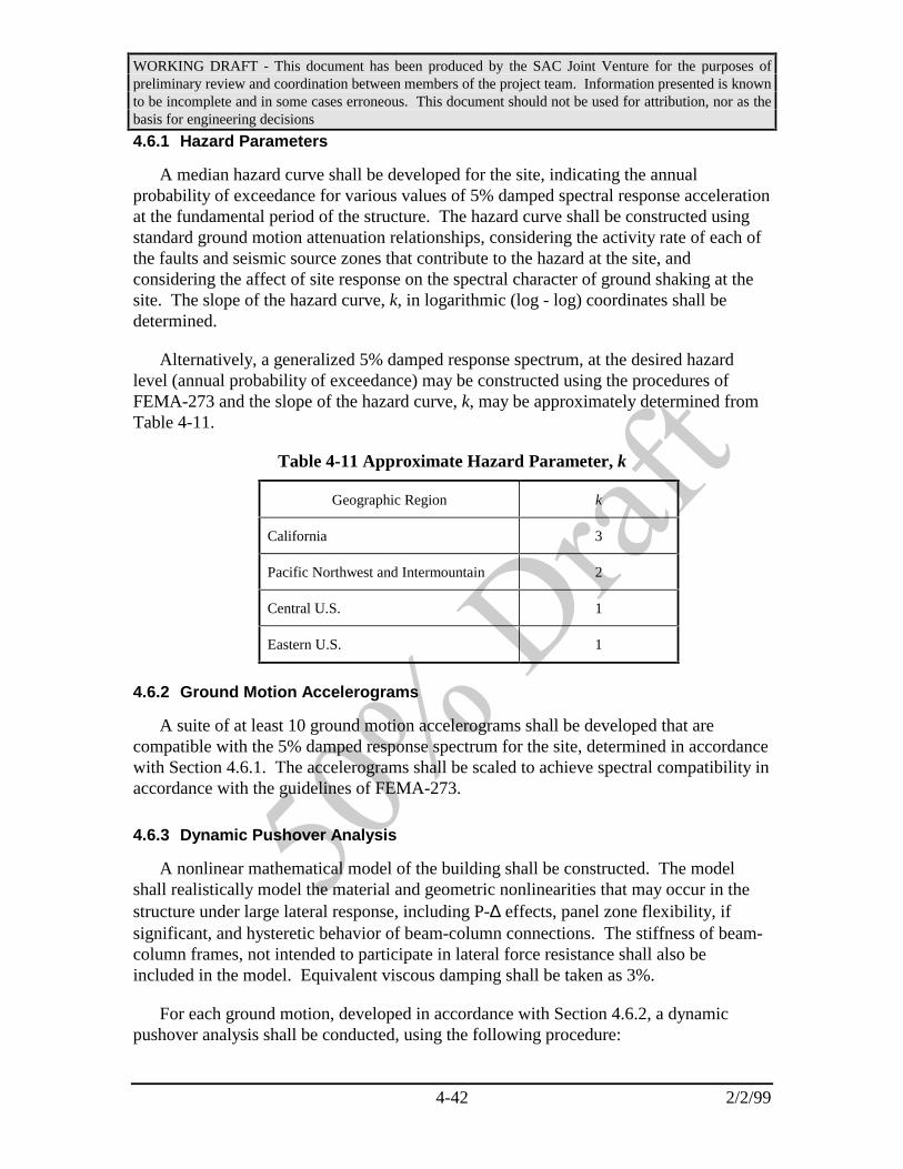
WORKING DRAFT - This document has been produced by the SAC Joint Venture for the purposes ofpreliminary review and coordination between members of the project team. Information presented is knownto be incomplete and in some cases erroneous. This document should not be used for attribution, nor as thebasis for engineering decisions
4-42 2/2/99
4.6.1 Hazard Parameters
A median hazard curve shall be developed for the site, indicating the annualprobability of exceedance for various values of 5% damped spectral response accelerationat the fundamental period of the structure. The hazard curve shall be constructed usingstandard ground motion attenuation relationships, considering the activity rate of each ofthe faults and seismic source zones that contribute to the hazard at the site, andconsidering the affect of site response on the spectral character of ground shaking at thesite. The slope of the hazard curve, k, in logarithmic (log - log) coordinates shall bedetermined.
Alternatively, a generalized 5% damped response spectrum, at the desired hazardlevel (annual probability of exceedance) may be constructed using the procedures ofFEMA-273 and the slope of the hazard curve, k, may be approximately determined fromTable 4-11.
Table 4-11 Approximate Hazard Parameter, k
Geographic Region k
California 3
Pacific Northwest and Intermountain 2
Central U.S. 1
Eastern U.S. 1
4.6.2 Ground Motion Accelerograms
A suite of at least 10 ground motion accelerograms shall be developed that arecompatible with the 5% damped response spectrum for the site, determined in accordancewith Section 4.6.1. The accelerograms shall be scaled to achieve spectral compatibility inaccordance with the guidelines of FEMA-273.
4.6.3 Dynamic Pushover Analysis
A nonlinear mathematical model of the building shall be constructed. The modelshall realistically model the material and geometric nonlinearities that may occur in thestructure under large lateral response, including P-∆ effects, panel zone flexibility, ifsignificant, and hysteretic behavior of beam-column connections. The stiffness of beam-column frames, not intended to participate in lateral force resistance shall also beincluded in the model. Equivalent viscous damping shall be taken as 3%.
For each ground motion, developed in accordance with Section 4.6.2, a dynamicpushover analysis shall be conducted, using the following procedure:

WORKING DRAFT - This document has been produced by the SAC Joint Venture for the purposes ofpreliminary review and coordination between members of the project team. Information presented is knownto be incomplete and in some cases erroneous. This document should not be used for attribution, nor as thebasis for engineering decisions
4-43 2/2/99
1. The ground motion shall be scaled to an index, spectral response accelerationat the fundamental period of the structure, that produces elastic response.
2. A response history analysis of the structure, for response to this ground motionshall be performed. The maximum inter-story drift obtained from the analysisshall be recorded.
3. The amplitude of the ground motion used in the analysis of step 2 shall bescaled to 110% of the amplitude used in that analysis.
4. Steps 2 and 3 shall be repeated, with the maximum inter-story drift predictedby each successive analysis recorded, until either the structure is predicted tocollapse by the analysis or maximum inter-story drift predicted by the analysisexceeds 10%.
5. A plot of the index spectral response acceleration at the structure’sfundamental period for each of the analyses and the maximum inter-story driftobtained from the analysis shall be created. This plot is termed a dynamicpushover plot.
Maximum Interstory Drift
Spe
ctra
l Res
opns
e A
ccel
erat
ion
- S
a
0 0.01 0.02 0.03 0.04 0.05 0.06
2.0
1.5
1.0
0.5
0
Predicted drift capacityCollapse Prevention Performance
Peak spectral accelerationcapacity
K1 0.8 K
1
Predicted drift capacityIncipient Damage Performance
Figure 4-2 Dynamic Pushover Curve
6. The slope of the initial portion of the dynamic pushover plot shall be noted. Aline shall be constructed from the origin of the dynamic pushover plot andhaving a slope of 80% of the slope of the initial portion of the dynamicpushover plot. The inter-story drift at the intersection of this line, having 80%of the slope of the initial portion of the curve, and the pushover curve itself,shall be taken as the inter-story drift capacity of the structure for collapseprevention performance, for this ground motion. The inter-story drift at whichthe slope of the global pushover curve deviates from the slope of the initialportion of the curve shall be taken as the inter-story drift capacity for incipient

WORKING DRAFT - This document has been produced by the SAC Joint Venture for the purposes ofpreliminary review and coordination between members of the project team. Information presented is knownto be incomplete and in some cases erroneous. This document should not be used for attribution, nor as thebasis for engineering decisions
4-44 2/2/99
damage performance. Refer to Figure 4-2. The inter-story drift capacity forcollapse prevention performance shall not be taken as greater than 0.1.
4.6.4 Determination of Factored Inter-story Drift Capacity
The inter-story drift capacities δi, determined from each of these analyses shall betabulated, together with the natural logarithm of these inter-story drift capacities, ln(δi).The median value of the δi statistics shall be determined, as shall the standard deviation,σlnδ of the natural logarithms of the inter-story drift capacities. A resistance factor, φ,shall be determined from the equation:
φσ δ
=−
ek
bln
2
2(4-17)
where: k = the slope of the hazard curve, determined in accordance with Section 4.6.1
b = a hazard parameter that may be taken as 1
σlnδ = the standard deviation of the natural logarithms of the predicted inter- story drifts obtained from the pushover analyses
Factored inter-story drift demand for global response shall be taken as the product ofφ determined in accordance with equation 4-17 and the median inter-story drift capacitydetermined from the dynamic pushover analyses.
4.6.5 Determination of Confidence Level
A performance confidence index, γcon, shall be determined in accordance with Section4.5, for each of the controlling performance parameters. The confidence parameter Kx,shall be determined from the equation, using the smallest of the values γcon:
Kb
kx
con
UT
UT= +ln( )γ
σσ2
(4-18)
where:k = the slope of the hazard curve, determined in accordance with Section 4.6.1b ;= a hazard parameter that may be taken as 1.0σUT = is a measure of the uncertainty related to prediction of drift demand, taken fromTable 4-12.
Table 4-12 Uncertainty Measures for Different Analytical Procedures
Analytical Procedure σUT

WORKING DRAFT - This document has been produced by the SAC Joint Venture for the purposes ofpreliminary review and coordination between members of the project team. Information presented is knownto be incomplete and in some cases erroneous. This document should not be used for attribution, nor as thebasis for engineering decisions
4-45 2/2/99
Linear Static Procedure 0.6
Linear Dynamic Procedure 0.7
Nonlinear Static Procedure 0.8
Nonlinear Dynamic Procedure 0.9
The level of confidence with regard to the target performance shall be determined byinterpolation from, Table 4-13.
Table 4-13 - Values of Kx for Various Levels of Confidence
Confidence Level KX
65% 0
84% 1
90% 1.3
95% 1.6

WORKING DRAFT - This document has been produced by the SAC Joint Venture for the purposes of preliminaryreview and coordination between members of the project team. Information presented is known to be incompleteand in some cases erroneous. This document should not be used for attribution, nor as the basis for engineeringdecisions
5-1 2/2/99
5. MATERIALS AND FRACTURE-RESISTANT DESIGN
5.1 Scope
This section provides guidelines on materials selection and the basic properties and behavior ofstructural steel materials recommended for application in MRSF structures. Reference is made tostandard industry specifications as well as recommended supplemental requirements for thesematerials. Guidance is provided on parent materials, welding materials and bolting. In addition,information is provided on the brittle fracture behavior of structural steel under certain conditions. Designers who are knowledgeable of the conditions that are conducive to the development of brittlefracture in steels can avoid many of these by applying appropriate practice in detailing andspecifying materials and workmanship requirements.
5.2 Parent Materials
5.2.1 Steels
Designers should specify materials that are readily available for building construction and thatwill provide suitable ductility and weldability for seismic applications. Structural steels that may beused in the lateral-force-resisting systems for structures designed for seismic resistance withoutspecial qualification include those contained in Table 5-1. Refer to the applicable ASTM referencestandard for detailed information.
Table 5-1 - Structural Steel Pre-qualified for Use in Seismic Lateral-Force-Resisting Systems
ASTM Specification DescriptionASTM A36 Carbon Structural SteelASTM A283Grade D
Low and Intermediate Tensile Strength Carbon Steel Plates
ASTM A500 (Grades B& C)
Cold-Formed Welded & Seamless Carbon Steel Structural Tubing in Rounds & Shapes
ASTM A501 Hot-Formed Welded & Seamless Carbon Steel Structural TubingASTM A572 (Grades42 & 50)
High-Strength Low-Alloy Columbium-Vanadium Steels of Structural Quality
ASTM A588 High-Strength Low-Alloy Structural Steel (weathering steel)ASTM A709 Structural Steel for BridgesASTM A913 High-Strength Low-Alloy Steel Shapes of Structural Quality, Produced by Quenching & Self-
Tempering ProcessASTM A992 Standard Specification for Steel for Structural Shapes for Use in Building Framing
Structural steels that may be used in the lateral-force-resisting systems of structures designed forseismic resistance with special permission of the building official are those listed in Table 5-2. Steel meeting these specifications has not been demonstrated to have adequate weldability orductility for general purpose application in seismic-force-resisting systems, although it may wellpossess such characteristics. In order to demonstrate the acceptability of these materials for such
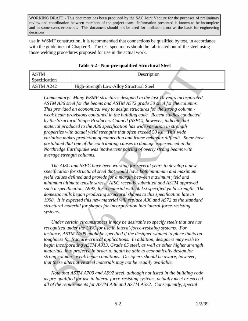
WORKING DRAFT - This document has been produced by the SAC Joint Venture for the purposes of preliminaryreview and coordination between members of the project team. Information presented is known to be incompleteand in some cases erroneous. This document should not be used for attribution, nor as the basis for engineeringdecisions
5-2 2/2/99
use in WSMF construction, it is recommended that connections be qualified by test, in accordancewith the guidelines of Chapter 3. The test specimens should be fabricated out of the steel usingthose welding procedures proposed for use in the actual work.
Table 5-2 - Non-pre-qualified Structural Steel
ASTMSpecification
Description
ASTM A242 High-Strength Low-Alloy Structural Steel
Commentary: Many WSMF structures designed in the last 10 years incorporatedASTM A36 steel for the beams and ASTM A572 grade 50 steel for the columns. This provided an economical way to design structures for the strong column -weak beam provisions contained in the building code. Recent studies conductedby the Structural Shape Producers Council (SSPC), however, indicate thatmaterial produced to the A36 specification has wide variation in strengthproperties with actual yield strengths that often exceed 50 ksi. This widevariation makes prediction of connection and frame behavior difficult. Some havepostulated that one of the contributing causes to damage experienced in theNorthridge Earthquake was inadvertent pairing of overly strong beams withaverage strength columns.
The AISC and SSPC have been working for several years to develop a newspecification for structural steel that would have both minimum and maximumyield values defined and provide for a margin between maximum yield andminimum ultimate tensile stress. AISC recently submitted and ASTM approvedsuch a specification, A992, for a material with 50 ksi specified yield strength. Thedomestic mills began producing structural shapes to this specification late in1998. It is expected this new material will replace A36 and A572 as the standardstructural material for shapes for incorporation into lateral-force-resistingsystems.
Under certain circumstances it may be desirable to specify steels that are notrecognized under the UBC for use in lateral-force-resisting systems. Forinstance, ASTM A709 might be specified if the designer wanted to place limits ontoughness for fracture-critical applications. In addition, designers may wish tobegin incorporating ASTM A913, Grade 65 steel, as well as other higher strengthmaterials, into projects, in order to again be able to economically design forstrong column - weak beam conditions. Designers should be aware, however,that these alternative steel materials may not be readily available.
Note that ASTM A709 and A992 steel, although not listed in the building codeas pre-qualified for use in lateral-force-resisting systems, actually meet or exceedall of the requirements for ASTM A36 and ASTM A572. Consequently, special

WORKING DRAFT - This document has been produced by the SAC Joint Venture for the purposes of preliminaryreview and coordination between members of the project team. Information presented is known to be incompleteand in some cases erroneous. This document should not be used for attribution, nor as the basis for engineeringdecisions
5-3 2/2/99
qualification of the use of this steel should not be required. Although A709 andA913 steels have not routinely been used in seismic applications, they both havebeen approved by AWS (D1.1 and D1.5) as weldable in pre-qualified connections.Because of the superior welding properties as compared to A-36 and A-572, it isexpected that A-992 will also be approved by AWS during the next approval cycle.
5.2.2 Chemistry
ASTM specifications define chemical requirements for each steel. A chemical analysis isperformed by the producer on each heat of steel. End product analyses can also be specified oncertain products. A certified mill test report is furnished to the customer with the material. Thedesigner should specify that copies of the mill test reports be submitted for his/her conformancereview. In general, ASTM specifications for structural steels include maximum limits on carbon,manganese, silicon, phosphorous and sulfur. Ranges and minimums are also limited on otherelements in certain steels. Chromium, columbium, copper, molybdenum, nickel and vanadium maybe added to enhance strength, toughness, weldability and corrosion resistance. These chemicalrequirements may vary with the specific product and shape within any given specification.
Commentary: Some concern has been expressed with respect to greater use ofrecycled steel in the production process. This results in added trace elements notlimited by current specifications. Although these have not been shownquantitatively to be detrimental to the performance of welding on the above steels,the new A-992 specification for structural steel does place more control on thesetrace elements. Mill test reports now include elements not limited in some or allof the specifications. They include copper, columbium, chromium, nickel,molybdenum, silicon and vanadium. The analysis and reporting of an expandedset of elements is required, and could be beneficial in the preparation of weldingprocedure specifications (WPSs) by the welding engineer if critical weldingparameters are required. Modern spectrographs used by the mills are capable ofautomated analyses. When required by the engineer, a request for specialsupplemental requirements beyond those listed above should be noted in thecontract documents.
5.2.3 Tensile/Elongation Properties
Mechanical property test specimens are taken from rolled shapes or plates at the rolling mill inthe manner and location prescribed by ASTM A6 and ASTM A370. Table 5-3 gives the basicmechanical requirements for commonly used structural steels. Properties specified and controlledby the mills in current practice include minimum yield strength, ultimate tensile strength andminimum elongation. However, there can be considerable variability in the actual properties ofsteel meeting these specifications. Table 5-4 presents statistical data on the range of strength valuesthat may be expected of contemporary steels meeting the indicated specifications. This data isbased on work performed by the Steel Shape Producers Council for the 1992 production year,supplemented by limited statistical surveys undertaken by the SAC project.
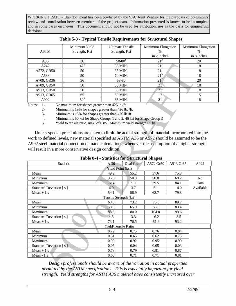
WORKING DRAFT - This document has been produced by the SAC Joint Venture for the purposes of preliminaryreview and coordination between members of the project team. Information presented is known to be incompleteand in some cases erroneous. This document should not be used for attribution, nor as the basis for engineeringdecisions
5-4 2/2/99
Table 5-3 - Typical Tensile Requirements for Structural Shapes
ASTMMinimum Yield
Strength, KsiUltimate Tensile
Strength, KsiMinimum Elongation
%in 2 inches
Minimum Elongation%
in 8 inchesA36 36 58-801 212 20A242 424 63 MIN. 213 18
A572, GR50 50 65 MIN. 212 18A588 50 70 MIN. 213 18
A709, GR36 36 58-80 212 20A709, GR50 50 65 MIN. 21 18A913, GR50 50 65 MIN. 21 18A913, GR65 65 80 MIN. 17 15
A992 505 65 MIN. 21 18Notes: 1- No maximum for shapes greater than 426 lb./ft.
2- Minimum is 19% for shapes greater than 426 lb. /ft.3- Minimum is 18% for shapes greater than 426 lb./ft.4. Minimum is 50 ksi for Shape Groups 1 and 2, 46 ksi for Shape Group 35. Yield to tensile ratio, max. of 0.85. Maximum yield strength 65 ksi.
Unless special precautions are taken to limit the actual strength of material incorporated into thework to defined levels, new material specified as ASTM A36 or A572 should be assumed to be theA992 steel material connection demand calculations, whenever the assumption of a higher strengthwill result in a more conservative design condition.
Table 8-4 - Statistics for Structural ShapesStatistic A 36 Dual Grade A572 Gr50 A913 Gr65 A922
Yield Point (ksi) Mean 49.2 55.2 57.6 75.3 Minimum 36.0 50.0 50.0 68.2 No Maximum 72.4 71.1 79.5 84.1 Data Standard Deviation [ s ] 4.9 3.7 5.1 4.0 Available Mean + 1 s 54.1 58.9 62.7 79.3
Tensile Strength (ksi) Mean 68.5 73.2 75.6 89.7 Minimum 58.0 65.0 65.0 83.4 Maximum 88.5 80.0 104.0 99.6 Standard Deviation [ s ] 4.6 3.3 6.2 3.5 Mean + 1 s 73.1 76.5 81.8 93.2
Yield/Tensile Ratio Mean 0.72 0.75 0.76 0.84 Minimum 0.51 0.65 0.62 0.75 Maximum 0.93 0.92 0.95 0.90 Standard Deviation [ s ] 0.06 0.04 0.05 0.03 Mean + 1 s 0.78 0.79 0.81 0.87 Mean - 1 s 0.66 0.71 0.71 0.81
Design professionals should be aware of the variation in actual propertiespermitted by the ASTM specifications. This is especially important for yieldstrength. Yield strengths for ASTM A36 material have consistently increased over

WORKING DRAFT - This document has been produced by the SAC Joint Venture for the purposes of preliminaryreview and coordination between members of the project team. Information presented is known to be incompleteand in some cases erroneous. This document should not be used for attribution, nor as the basis for engineeringdecisions
5-5 2/2/99
the last 15 years so that several grades of steel may have the same properties orreversed properties, with respect to beams and columns, from those the designerintended. Investigations of structures damaged by the Northridge earthquakefound some WSMF connections in which beam yield strength exceeded columnyield strength despite the opposite intent of the designer.
With the ASTM approval of the A992 structural steel, the production of dualcertified steel (A36 and A572) probably will not occur. Similarly, it is unlikelythat A36 or A572 steel will continue to be produced as structural shapes. Because it is produced as a single grade, it is unlikely that the A992 steel willhave as much variation in properties as was experienced with the dual gradesteels. However, it is uncertain as ot the future of A36 and A572 grades of steelin plate material. Because steel service centers carry inventories of A36, A572,and dual grade steel, it is advisable to be aware of the possibility that for a fewyears, structural shapes of this type may be incorporated in projects unlessprecautions are taken.
5.2.4 Toughness Properties
For critical connections, non-redundant components and unusual or difficult geometriesinvolving Group 3 (with flanges 11/2 inches or thicker) 4 and 5 shapes and plates and built-upsections over two inches thick with welded connections, the designer should consider specifyingtoughness requirements on the parent materials. A Charpy V-Notch (CVN) value of 20 ft.-lb. at 70degrees F. should be specified when toughness is deemed necessary for an application. Refer toFigure 5-1 for typical CVN test specimen locations. The impact test should be conducted inaccordance with ASTM A673, frequency H, with the following exceptions:
a) The center longitudinal axis of the specimens should be located as near as practicable tomidway between the inner flange surface and the center of the flange thickness at theintersection of the web mid-thickness. Refer to AISC LRFD specification, Section A3-1c, Heavy Shapes (American Institute of Steel Construction - 1993)
b) Tests should be conducted by the producer on material selected from a locationrepresenting the top of each ingot or part of an ingot used to produce the productrepresented by these tests. For the continuous casting process, the sample may be takenat random throughout the length of the beam or column. If rotary straightening is usedto straighten the shape after cooling, test samples should be taken from the k-area asshown in Figure 5-1.

WORKING DRAFT - This document has been produced by the SAC Joint Venture for the purposes of preliminaryreview and coordination between members of the project team. Information presented is known to be incompleteand in some cases erroneous. This document should not be used for attribution, nor as the basis for engineeringdecisions
5-6 2/2/99
TypicalCVNSpecimenASTM A673
tf/2
CLbf/2bf/3
CVNSpecimenAISC- LRFDA3-1cRecommended test
location for rotarystraightened sections
Figure 5-1 - Standard Locations for Charpy V-Notch Specimen Extraction, LongitudinalOnly
Commentary: Specifying toughness properties in critical, unusual or non-redundant connections should be considered. As temperature decreases or strainrate increases, toughness properties decrease. Charpy V-notch impact (CVN)tests, pre-cracked CVN tests and other fracture toughness tests can identify the nilductility temperature (NDT) - the temperature below which a material loses allductility and fractures in a brittle manner. On a microscopic level, this equates toa change in the fracture mechanism from shear to cleavage. Fracture that occursby cleavage at a nominal tensile stress below yield is referred to as a brittlefracture. A brittle fracture can occur in structural steel when a particularcombination of low temperature, tensile stress, high strain rate and ametallurgical or mechanical notch is present.
Plastic deformation can only occur through shear stress. Shear stress isgenerated when uniaxial or bi-axial straining occurs. In tri-axial stress states,the maximum shear stress approaches zero as the principal stresses increase. When these stresses approach equality, a cleavage failure can occur. Weldingand other sources of residual stresses in combination with yield level seismicgenerated stresses can set up a state of tri-axial stress leading to brittle fractures,if the connection is not properly detailed.
The necessity for minimum toughness requirements is not agreed to by all. There is also disagreement as to how much toughness should be required. TheAWS Presidential Task Group recommended minimum weld metal toughnessvalues of 20 ft-lb. at various temperatures, depending on the anticipated serviceconditions. For base metal, a toughness of 15 ft-lbs at a temperature of 70

WORKING DRAFT - This document has been produced by the SAC Joint Venture for the purposes of preliminaryreview and coordination between members of the project team. Information presented is known to be incompleteand in some cases erroneous. This document should not be used for attribution, nor as the basis for engineeringdecisions
5-7 2/2/99
degrees F was recommended for enclosed structures and 40 degrees F forexposed structures. The 1993 AISC LRFD Specification, Section A3-1c, HeavyShapes, requires toughness testing [Charpy V-Notch] under the followingconditions for Group 4 and 5 shapes and plates exceeding 2 inches in thickness:a) When spliced using complete joint penetration welds; b) when complete jointpenetration welds through the thickness are used in connections subjected toprimary tensile stress due to tension or flexure of such members.” Wheretoughness is required, the minimum value should be 20 ft-lb. at 70°F.
Plates thicker than two inches and sections with flanges thicker than 1-1/2inches can be expected to have significantly variable grain sizes across thesection. The slower cooling rate of the web-flange intersection in thick sectionsproduces a larger grain size which exhibits less ductility and notch toughness.
ANSI/ASTM A673 and A370 establish the procedure for longitudinal CharpyV-notch testing. The impact properties of steel can vary within the same heat andpiece, be it as-rolled, controlled rolled, or heat treated. Normalizing orquenching and tempering will reduce the degree of variation. Three specimensare taken from a single test coupon or location. The average value of Charpytoughness obtained from the three specimens must exceed the specified minimum.One of the tested values may be less than the specified minimum but must begreater than the larger of two thirds of the specified minimum or 5 ft-lb,whichever is greater. The longitudinal axis of the specimen is parallel to thelongitudinal axis of the shape or final rolling direction for plate. For shapes, thespecimen is taken from the flange 1/3 the distance from the edge of the flange tothe web. The frequency of testing [heat or piece], the test temperature, and theabsorbed energy are specified by the user. [NOTE: heat testing (frequency H) forshapes, means one CVN test set of samples from at least each 50 tons of the sameshape size, excluding length, from each heat in the as-rolled condition. Piecetesting (frequency P) for shapes, means one CVN test set of specimens from atleast each 15 tons or each single length of 15 tons of the same shape size,excluding length, from each heat in the as-rolled condition.] Heat testing isprobably adequate in most circumstances.
The specimen location required by ASTM A673 is not at the least tough partof a W shape. For a W shape, the volume at the flange web intersection hashistorically had the lowest ratio of surface area to volume and hence cools theslowest. This slow cooling causes grain growth and reduced toughness. Thefiner the grain, the tougher the material. Also, ASTM A673 does not specifywhere in the product run of an ingot to sample. Impurities tend to rise to theupper portion of the ingot during cooling from molten metal. Impurities reducethe toughness of the finished metal. Hence, shapes produced from the upperportions of an ingot can be expected to have lower toughness, and samples shouldbe taken from shapes produced from this portion of the ingot. In the continuous

WORKING DRAFT - This document has been produced by the SAC Joint Venture for the purposes of preliminaryreview and coordination between members of the project team. Information presented is known to be incompleteand in some cases erroneous. This document should not be used for attribution, nor as the basis for engineeringdecisions
5-8 2/2/99
casting process, impurities tend to be more evenly distributed; hence, samplestaken anywhere should suffice. The AISC LRFD specification requires testingfrom the upper portion of the ingot and near the web flange intersection. Recenttests at Lehigh (Ref. ) on new continuous cast shapes and one old shape recoveredfrom a building indicate that through-thickness properties of column flanges arenot a concern.
In response to concerns raised following the Northridge Earthquake, the AISCconducted a statistical survey of the toughness of material produced in structuralshapes, based on data provided by six producers for a production period ofapproximately one year (American Institute of Steel Construction - 1995). Thissurvey showed a mean value of Charpy V notch toughness for all shape groupsthat was well in excess of 20 ft-lb. at 70 degrees F. However, not all of thesamples upon which these data are based were taken from the core area, nor atthe k-area recommended by these Guidelines. Consequently, this survey does notprovide definitive information on the extent to which standard material producedby the mills participating in this survey will meet the recommended values.
Rotary straightening of steel wide flange shapes produces large shear strainsat the k-area that has been found to reduce the CVN toughness to low single digittoughness (Tide, 1997a, b). While this has not been demonstrated to have adverseaffects on in-service performance of structural steel, it has been associated withfabrication related fractures.
5.2.5 Lamellar Discontinuities
For critical joints (beam to column CJP welds or other tension applications where Z-axis or tri-axial stress states exist), ultrasonic testing (UT) should be specified for the member loaded in the Zaxis direction, in the area of the connection. A distance 3 inches above and below the location to bewelded to the girder flange is recommended. The test procedure and acceptance criteria given inASTM A898-91, Standard Specification for Straight Beam Ultrasonic Examination of Rolled SteelStructural Shapes, Level I, should be applied. This testing should be done in the mill or fabricationshop for new construction.
The possible occurrence of lamellar tearing can be minimized by following recommendedprocedures for welding highly restrained joints. These include detailing (AISC Ref. ), preheatingjoint to temperatures in excess of the minimum requirements of AWS for the steel thicknessesinvolved in the connection and buttering layers of ductile and tough weld metal in the joint in thethrough-thickness direction.
Commentary: Prior to the Northridge earthquake very little test data existed onthe through thickness properties of structural shapes nor were there any standardtest methods for determining these properties. Nevertheless, the typical beam-column joints typically used in welded FR connections prior to the Northridge
WORKING DRAFT - This document has been produced by the SAC Joint Venture for the purposes of preliminaryreview and coordination between members of the project team. Information presented is known to be incompleteand in some cases erroneous. This document should not be used for attribution, nor as the basis for engineeringdecisions
5-9 2/2/99
earthquake placed significant through-thickness demands on the flanges ofcolumns and some fractures observed in damaged buildings following theNorthridge earthquake were identified as potentially being the result of through-thickness failures of the material. Lamellar tearing, a form of through-thicknessfailure, had been a problem in the fabrication of heavy structural frames duringthe 1970s and this was again suspected to be a cause of some of these failures.
Extensive testing conducted as part of the SAC phase II investigationsindicates that the through thickness strength of column shapes is not a significantlimiting factor on connection behavior. Nevertheless, there is some potential forfabrication induced lamellar tearing of heavy weldments, particularly in steelshaving high sulfur contents. Laminations (pre-existing planes of weakness) andlamellar tearing (cracks parallel to the surface) will impair the Z axis strengthand toughness properties of column material. These defects are mainly caused bynon-metallic sulfides and oxides which begin as almost spherical in shape, andbecome elongated in the rolling process. When Z axis loading occurs from weldshrinkage strains or external loading, microscopic cracks may form between thediscrete, elongated nonmetallic inclusions. As they link up, lamellar tearingoccurs.
Longitudinal wave ultrasonic testing is very effective in mapping seriouslamination discontinuities. Improved quality steel does not eliminate weldshrinkage and, by itself, will not necessarily avoid lamellar tearing in highlyrestrained joints. Ultrasonic testing should not be specified without due regardfor design and fabrication considerations.
In cases where lamellar defects or tearing are discovered in erection or onexisting buildings, the designer should consider the consequences of makingrepairs to these areas. Gouging and repair welding will add additional cycles ofweld shrinkage to the connection and may promote crack extensions or newlamellar tearing. If weld repairs are attempted, carefully though out repairdetailing and weld procedure specifications (WPS) should be prepared inadvance.
5.3 Welding
5.3.1 Welding Process
Applicable welding processes for structural steel construction include shielded metal arcwelding (SMAW), flux cored arc welding (FCAW), submerged arc welding (SAW), and gas metalarc weld (GMAW). Fabricators and erectors should be permitted to select the most appropriateprocess for each individual joint, given the limitations of access, production and workerqualifications. Contract documents should specify required strength and toughness properties forwelding and usually should not attempt to limit process selection. Under some special conditions,

WORKING DRAFT - This document has been produced by the SAC Joint Venture for the purposes of preliminaryreview and coordination between members of the project team. Information presented is known to be incompleteand in some cases erroneous. This document should not be used for attribution, nor as the basis for engineeringdecisions
5-10 2/2/99
including unusual base material chemistry or service conditions, some restrictions on weldprocesses or parameters may be appropriate and should be stated in the contract documents.
5.3.2 Welding Procedures
Welding should be performed within the parameters established by the electrode manufacturerand the Welding Procedure Specification (WPS), required under AWS D1.1. Either pre-qualifiedor qualified-by-test procedures may be utilized, if the procedure is capable of producing weld of thedesired quality.
Commentary: Welding procedure specifications should be prepared by thefabricator and/or erector and should specify all parameters that must becontrolled in making the weld. For example, the position (if applicable),electrode diameter, amperage or wire feed speed range, voltage range, travelspeed range and electrode stickout (e.g. all passes, 0.072 in. diameter, 248 to 302amps, 19 to 23 volts, 6 to 10 inches/minute travel speed, 170 to 245 inches/minutewire feed speed, 1/2" to 1" electrode stickout) should be established. Itsimportance in producing a high quality weld is essential. The followinginformation is presented to help the engineer understand some of the issuessurrounding these parameters.
The amperage, voltage, travel speed, electrical stickout and wire feed speedare functions of each electrode. If pre-qualified WPSs are utilized, theseparameters must be in compliance with the AWS D1.1 requirements. For FCAWand SMAW, the parameters required for an individual electrode vary frommanufacturer to manufacturer. Therefore, for these processes, it is essential thatthe fabricator/erector utilize parameters that are within the range ofrecommended operation published by the filler metal manufacturer. Alternately,the fabricator/erector could qualify the welding procedure by test in accordancewith the provisions of AWS D1.1 and base the WPS parameters on the test results.For submerged arc welding, the AWS D1.1 code provides specific amperagelimitations since the solid steel electrodes used by this process operate essentiallythe same regardless of manufacture. The filler metal manufacturer’s guidelineshould supply data on amperage or wire feed speed, voltage, polarity, andelectrical stickout. The guidelines will not, however, include information ontravel speed which is a function of the joint detail. The contractor should select abalanced combination of parameters, including travel speed, that will ensure thatthe code mandated weld-bead sizes (width and height) are not exceeded.
5.3.3 Welding Filler Metals
The current AWS D1.1 requirements should be incorporated as written in the Code. Thewelding parameters should be clearly specified using a combination of the Project Specifications,the Project Drawings, the Shop Drawings and the welding procedure specifications, as required by

WORKING DRAFT - This document has been produced by the SAC Joint Venture for the purposes of preliminaryreview and coordination between members of the project team. Information presented is known to be incompleteand in some cases erroneous. This document should not be used for attribution, nor as the basis for engineeringdecisions
5-11 2/2/99
AWS D1.1. For welding on ASTM A572 steel, the AWS D1.1 code requires the use of low-hydrogen electrodes. Low hydrogen practice should be specified regardless of the steel grade. With SMAW welding, a variety of non-low hydrogen electrodes are commercially available. Theseelectrodes are not appropriate for welding on the higher strength steels used in building constructiontoday, although they were popular in the past when lower strength steels were employed. All of theelectrodes that are employed for flux cored arc welding (both gas shielded and self-shielded), aswell as submerged arc welding, are considered low hydrogen. However, in some cases, the lowhydrogen consideration is based on coupons that are artificially aged (Ref. AWS). Becausedeposited weld metal is not artificially aged, caution should be exercised and appropriatedocumentation obtained before automatically accepting a low hydrogen rating.
For critical joints (beam to column CJP welds or other CJP tension applications where transvereloading or applied tri-axial stress states exist), toughness requirements for the filler metals shouldbe specified. A minimum CVN value of 20 ft.-lb. at a temperature of -20 degrees F. should berequired, unless more stringent requirements are indicated by the service conditions and/or theContract Documents. The filler metal should be tested in accordance with the AWS A5 filler metalspecification to ensure it is capable of achieving this level of notch toughness. The filler metalmanufacturers Typical Certificate of Conformance, or a suitably documented test performed by thecontractor, should be used to document the suitability of the electrode used. These tests should beperformed for each filler metal by AWS classification, filler metal manufacturer and filler metalmanufacturer’s trade name. The sizes as specified by the AWS A5 document should be tested,although the exact diameter used in production need not be specifically tested. This requirementshould not be construed to imply lot or heat testing of filler metals.
Electrode specification sheets should be provided by the Fabricator/Erector prior tocommencing fabrication/erection.
Commentary: Although there are no notch toughness requirements for weldmetal used in welding ASTM A 36 or A 572, Grade 50, A709, A913 and A992steel under AWS D1.1, research conducted since the Northridge earthquakeclearly demonstrates the benefits of incorporating notch tough weld metal incritical joints of MRSF construction. Most filler metals are fairly notch tough,but some will not achieve even a modest requirement such as 5 ft-lb. at + 70°F. These guidelines recommend that critical joints be made with weld filler metalwith rated notch toughness of 20 ft-lbs at-20oF.
Welding electrodes for common welding processes include:
AWS A5.20: Carbon Steel Electrodes for FCAWAWS A5.29: Low Alloy Steel Electrodes for FCAWAWS A5.1: Carbon Steel Electrodes for SMAWAWS A5.5: Low Alloy Steel Covered Arc Welding Electrodes (for SMAW)AWS A5.17: Carbon Steel Electrodes and Fluxes for SAWAWS A5.23: Low Alloy Steel Electrodes and Fluxes for SAW

WORKING DRAFT - This document has been produced by the SAC Joint Venture for the purposes of preliminaryreview and coordination between members of the project team. Information presented is known to be incompleteand in some cases erroneous. This document should not be used for attribution, nor as the basis for engineeringdecisions
5-12 2/2/99
AWS A5.25: Carbon and Low Alloy Steel Electrodes and Fluxes for ElectroslagWelding
In flux cored arc welding, one would expect the use of electrodes that meeteither AWS A5.20 or AWS A5.29 provided they meet the toughness requirementsspecified below.
Except to the extent that one requires Charpy V-Notch toughness andminimum yield strength, the filler metal classification is typically selected by theFabricator. As an aid to the engineer, the following interpretation of filler metalclassifications is provided below:
E1X2X3T4X5 For electrodes specified under AWS A5.20E1X2X3T4X5X6 For electrodes specified under AWS A5.29E1XX7X8X9X10 For electrodes specified under AWS A5.1 or AWS A5.5.
NOTES:
1. Indicates an electrode.
2. Indicates minimum tensile strength of deposited weld metal (in tens of ksi, e.g., 7 = 70ksi).
3. Indicates primary welding position for which the electrode is designed (0 = flat andhorizontal and 1 = all positions).
4. Indicates a flux cored electrode. Absence of a letter indicates a "stick" electrode forSMAW.
5. Describes usability and performance capabilities. For our purposes, it conveyswhether or not Charpy V-Notch toughness is required (1, 5, 6 and 8 have impactstrength requirements while 2, 4, 7, 10 and 11 do not). A "G" signifies that theproperties are not defined by AWS and are to be agreed upon between themanufacturer and the specifier. Impact strength is specified in terms of the number offoot-pounds at a given temperature (e.g., 20 ft-lb. at 0 degrees F). Note that forelectrodes specified under AWS A5.20, the format for usage is "T-X".
6. Designates the chemical composition of deposited metal for electrodes specified underAWS A5.29. Note that there is no equivalent format for chemical composition forelectrodes specified under AWS A5.20.
7. The first two digits (or three digits in a five digit number) designate the minimumtensile strength in ksi.
8. The third digit (or fourth digit in a five digit number) indicates the primary weldingposition for which the electrode is designed (1 = all positions, 2 = flat position and

WORKING DRAFT - This document has been produced by the SAC Joint Venture for the purposes of preliminaryreview and coordination between members of the project team. Information presented is known to be incompleteand in some cases erroneous. This document should not be used for attribution, nor as the basis for engineeringdecisions
5-13 2/2/99
fillet welds in the horizontal position, 4 = vertical welding with downward progressionand for other positions.)
9. The last two digits, taken together, indicate the type of current with which the electrodecan be used and the type of covering on the electrode.
10. Indicates a suffix (e.g., A1, A2, B1, etc.) designating the chemical composition of thedeposited metal.
Electrode Diameter: (See AWS D1.1 Section 4.14.1.2) Electrode diameter effectsthe rate of weld metal deposition and the heat imparted to the metal duringwelding. This can effect toughness of the completed joint. The following lists themaximum allowable electrode diameters for pre-qualified FCAW WPS’saccording to D1.1:
• Horizontal, complete or partial penetration welds: 1/8 inch (0.125")*• Vertical, complete or partial penetration welds: 5/64 inch (0.078")• Horizontal, fillet welds: 1/8 inch (0.125")• Vertical, fillet welds: 5/64 inch (0.078")• Overhead, reinforcing fillet welds: 5/64 inch (0.078")
* This value is not part of D1.1-94, but will be part of D1.1-96.
For a given electrode diameter, there is an optimum range of weld bead sizesthat may be deposited. Weld bead sizes that are outside the acceptable size range(either too large or too small) may result in unacceptable weld quality. The D1.1code controls both maximum electrode diameters and maximum bead sizes (widthand thickness). Pre-qualified WPS’s are required to meet these coderequirements. Further restrictions on suitable electrode diameters are notrecommended.
5.3.4 Preheat and Interpass Temperatures
The preheat temperatures and conditions given in AWS D1.1, Chapter 3 should be strictlyobserved with special attention given to Section 3.2, for the thickness of metal to be welded. Forrepair welding of earthquake damage, the AASHTO/AWS D1.5 Bridge Welding Code, Chapter 12preheat requirements for fracture-critical applications should be considered.
Cracking of welds and heat affected zones should be avoided. One type of weld cracking ishydrogen induced cracking (HIC). For a given steel, variables that reduce HIC tendencies areprioritized as follows:
1. Lower levels of hydrogen.
2. Higher preheat and interpass temperatures.
3. Postheat.
WORKING DRAFT - This document has been produced by the SAC Joint Venture for the purposes of preliminaryreview and coordination between members of the project team. Information presented is known to be incompleteand in some cases erroneous. This document should not be used for attribution, nor as the basis for engineeringdecisions
5-14 2/2/99
4. Retarded cooling (insulating blankets).
Only low hydrogen electrodes should be used for fabrication and/or erection of seismicallyloaded structures. Proper preheat and interpass temperatures should be maintained. AWS D1.1requirements are generally adequate for new construction.
Control of hydrogen and proper preheat and interpass temperature is much more powerful forovercoming HIC than postheat or retarded cooling methods. Retarded cooling has limited benefit ifthe entire piece is not preheated - obviously impractical for structural applications.
The engineer is encouraged to emphasize proper preheat and the use of low hydrogen electrodesand practice. If these measures are insufficient to prevent cracking, additional measures may berequired to eliminate cracking. These measures may or may not call for additional preheat,postheat, or retarded cooling.
While low hydrogen electrodes and proper preheat is essential, postheat and retarded cooling isnot generally required and should not be used for routine construction.
Commentary: There are two primary purposes for preheating and interpasstemperature requirements:
(1) To drive off any surface moisture or condensation which may be presenton the steel so as to lessen the possibility of hydrogen being introduced into theweld metal and HAZ, and
(2) To prevent the steel mass surrounding the weld from quenching the HAZas cooling occurs after welding.
Virtually all weld repairs are made under conditions of high restraint. Consequently, higher preheat/interpass temperatures may be required for repairapplications. As steel is cooled from the austenitic range (above about 1330degrees F), it goes through a critical transition temperature. If it goes throughthat temperature range too fast, a hard, brittle phase called martensite forms(quenching). If it passes through that temperature range at a slower rate, ductile,tougher phases called bainite or ferrite/pearlite form. Preheating of thesurrounding mass provides a slower cooling rate for the weld metal and HAZ.
ANSI/AASHTO/AWS D1.5 recognizes repair welding as more critical in itsguidelines for the repair of fracture-critical bridge members. The purpose, inpart, is to allow more plastic flow and yielding, at welding temperatures, in thearea near the weld. The requirements are given in Table 5-6:
Table 5-6 - ANSI/AASHTO/AWS D1.5 Preheat Requirements for Fracture Critical RepairsSteel Thickness, in. Minimum Preheat/Interpass
Temp., °F
WORKING DRAFT - This document has been produced by the SAC Joint Venture for the purposes of preliminaryreview and coordination between members of the project team. Information presented is known to be incompleteand in some cases erroneous. This document should not be used for attribution, nor as the basis for engineeringdecisions
5-15 2/2/99
A36/A572 to 1-1/2 325A36/A572 >1-1/2 375
Preheat temperatures should be measured at a distance from the weld equalto the thickness of the part being welded, but not less than three inches, in anydirection including the through thickness of the piece. Where plates are ofdifferent thicknesses, the pre-heat requirement for the thicker plate should govern.Maintenance of these temperatures through the execution of the weld (i.e. theinterpass temperature) is essential. Maximum interpass temperatures should belimited to 550 degrees F for pre-qualified WPSs for fracture-critical applications. Higher interpass temperatures could be employed if those higher temperaturelimits are qualified by test.
5.3.5 Postheat
Postheat is the application of heat in the 400 degrees F to 600 degrees F range after completionof welding. It may be helpful in mitigating some cracking tendencies.
Commentary: A postheat specification might require that complete jointpenetration groove welds in existing buildings be postheated at 450 degrees F fortwo hours. The purpose of this postheat is to accelerate the removal of hydrogenfrom the weld metal and HAZ and reduce the probability of cracking due tohydrogen embrittlement. Hydrogen will migrate within the weld metal atapproximately 1 inch per hour at 450 degrees F, and at about 1 inch per month at70 degrees F. To the extent that hydrogen embrittlement is of concern, postheat isone method of mitigating cracking. The use of low hydrogen electrodes, properwelding procedures, and uniformly applied and maintained preheat mayrepresent a cost-effective method of addressing the problem of hydrogenembrittlement in lieu of postheat.
When postheat is required, AASHTO/AWS D1.5-95 specifications require thisto be done immediately upon completion of welding. The postheat is between 400to 500 degrees F for one hour minimum, for each inch of the thickest member orfor two hours, whichever is less.
5.3.6 Controlled Cooling
Most of the weldment cooling occurs by conductance within the steel rather than radiation. Retarded cooling should only be specified in cases where large weldments subject to significantresidual stresses due to restraint (e.g. multiple members framing into one connection with Z axisloading) or ambient temperatures that would result in rapid cooling of large weldments. The lengthof time to cool down the weld and the level of insulation required are a function of weldmenttemperature, thickness of base metal and ambient temperature.

WORKING DRAFT - This document has been produced by the SAC Joint Venture for the purposes of preliminaryreview and coordination between members of the project team. Information presented is known to be incompleteand in some cases erroneous. This document should not be used for attribution, nor as the basis for engineeringdecisions
5-16 2/2/99
Commentary: Active systems of ramp-down cooling are generally not required;however, in highly restrained conditions they may offer an advantage.
5.3.7 Metallurgical Stress Risers
Metallurgical discontinuities such as tack welds, air-arc gouging and flame cutting withoutpreheating or incorporation into the final weld should not be permitted. Inadvertent damage of thistype should be repaired by methods approved by the engineer, following the AWS D1.1 criteria anda specific WPS covering repairs of this type.
Commentary: Metallurgical stress risers may result from tack welds, air-arcgouging and flame cutting performed without adequate preheat. However,preheating is not necessarily required for air arc gouging or flame cutting used inthe preparation of a surface to receive later welding. The subsequent heat inputduring the welding process should adequately anneal the affected area. The AWSD1.1 code requires the same preheating for tack welding operations as normalwelding, with the exception of tack welds that are incorporated into subsequentsubmerged arc weld deposits.
Arc strikes can also be a source of metallurgical stress risers and should notbe indiscriminately made. AWS D1.1 Section 5.29 indicates that “arc strikesoutside the area of permanent welds should be avoided on any base metal. Cracks or blemishes caused by arc strikes should be ground to a smooth contourand checked to ensure soundness.”
5.4 Bolting
Structural bolts employed in connections of MRSFs should conform to one of the standardtypes indicated in Table 5-7 and to the applicable requirements of the ASTM specifications.
Table 5-7 - Structural Bolts for Moment-Resisting Steel Frame ConstructionSpecification Description Remarks
ASTM A307 Carbon Steel Bolts and Studs, 60,000 psiTensile Strength
Should not be used in combination withwelds on the same joint
ASTM A325 High Strength Bolts for Structural SteelJoints
Should not be used in the same plane incombination with welds to transfer loads
ASTM A490 Heat-treated Steel Structural Bolts, 150 ksiminimum tensile strength
5.5 Fracture Mechanics Principles
This section provides basic information on the principles of fracture mechanics.
Commentary: Structural steel and weld metal are generally regarded as a ductilematerial capable of extensive inelastic deformation prior to development oftensile fractures. However, under certain condition, these highly ductile

WORKING DRAFT - This document has been produced by the SAC Joint Venture for the purposes of preliminaryreview and coordination between members of the project team. Information presented is known to be incompleteand in some cases erroneous. This document should not be used for attribution, nor as the basis for engineeringdecisions
5-17 2/2/99
materials can behave in a brittle manner resulting in the development of unstablefractures with relatively little plastic deformation. The conditions that can lead tosuch brittle behavior and engineering approaches to judging the severity of theseconditions are presented in this section.
5.5.1 Introduction
Brittle fracture can be described as a dynamic propagation of an unstable crack. Brittle fractureoccurs when the state-of-stress at the crack tip reaches a critical magnitude resulting in an unstablecrack. The relationship between stress, stress intensity factor and crack size is given by therelationship:
K F a= σ π
where:K = stress intensity factor, ksi (in)1/2
F = non-dimensional constantσ = nominal stress, ksia = crack size, in.
5.5.2 Crack Geometry
The non-dimensional term, F, allows for various geometric conditions in the vicinity of thecrack (a) including crack location and size relative to the primary member. Evaluation of crackslocated on the surface, subsurface, edge or through the full thickness, etc. of the member eachrequire a different value of the coefficient F. Methods for determining F are documented in theliterature (Barsom - 1987, Tada - 1985 and Fisher - 1984). In welded structures, initial cracks canresult from weld discontinuities such as porosity, slag inclusions, lack-of-fusion, undercut andbacking bar notches.
5.5.3 Stress Variables
Conventional engineering mechanics techniques are used to compute the nominal stress (σ) atthe crack tip. In addition to stresses resulting from external forces, residual stresses from weldingmust be considered when welded connections are involved.
5.5.4 Stress Intensity Factor
The stress intensity factor (K) at the crack tip is calculated and compared to the notch toughnessof the material in the vicinity of the crack. The appropriate notch toughness must be determined forthe comparison to be valid. Specifically, it must be decided whether the stress intensity factor iscompared to notch toughness based on a plane stress (Kc) or plane strain (KIc) condition for slowloading or a plane strain condition (KId) for dynamic loading. If the stress intensity factor is less
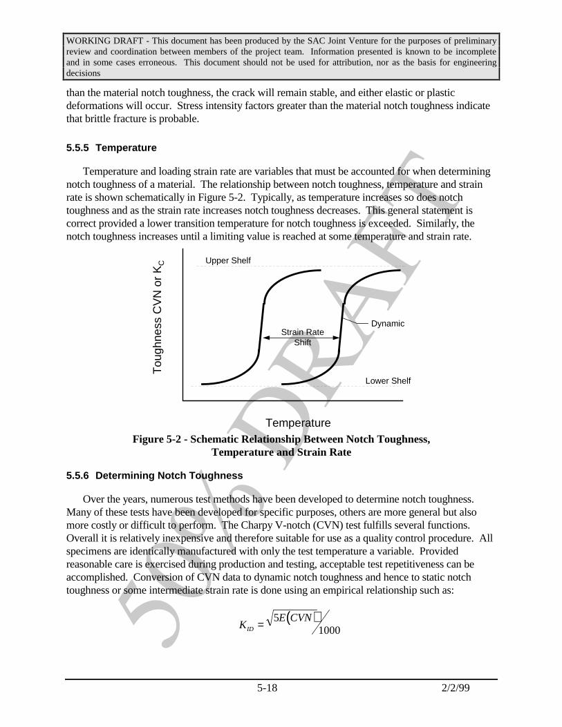
WORKING DRAFT - This document has been produced by the SAC Joint Venture for the purposes of preliminaryreview and coordination between members of the project team. Information presented is known to be incompleteand in some cases erroneous. This document should not be used for attribution, nor as the basis for engineeringdecisions
5-18 2/2/99
than the material notch toughness, the crack will remain stable, and either elastic or plasticdeformations will occur. Stress intensity factors greater than the material notch toughness indicatethat brittle fracture is probable.
5.5.5 Temperature
Temperature and loading strain rate are variables that must be accounted for when determiningnotch toughness of a material. The relationship between notch toughness, temperature and strainrate is shown schematically in Figure 5-2. Typically, as temperature increases so does notchtoughness and as the strain rate increases notch toughness decreases. This general statement iscorrect provided a lower transition temperature for notch toughness is exceeded. Similarly, thenotch toughness increases until a limiting value is reached at some temperature and strain rate.
Tou
ghne
ss C
VN
or
KC
Temperature
Lower Shelf
Upper Shelf
DynamicStrain Rate
Shift
Figure 5-2 - Schematic Relationship Between Notch Toughness,Temperature and Strain Rate
5.5.6 Determining Notch Toughness
Over the years, numerous test methods have been developed to determine notch toughness. Many of these tests have been developed for specific purposes, others are more general but alsomore costly or difficult to perform. The Charpy V-notch (CVN) test fulfills several functions. Overall it is relatively inexpensive and therefore suitable for use as a quality control procedure. Allspecimens are identically manufactured with only the test temperature a variable. Providedreasonable care is exercised during production and testing, acceptable test repetitiveness can beaccomplished. Conversion of CVN data to dynamic notch toughness and hence to static notchtoughness or some intermediate strain rate is done using an empirical relationship such as:
( )K
E CVNID = 5
1000
WORKING DRAFT - This document has been produced by the SAC Joint Venture for the purposes of preliminaryreview and coordination between members of the project team. Information presented is known to be incompleteand in some cases erroneous. This document should not be used for attribution, nor as the basis for engineeringdecisions
5-19 2/2/99
where:KID = dynamic notch toughness ksi (in)1/2
E = modulus of elasticity, psiCVN = Charpy V-notch, ft-lbs
and for structural steels:
T Fshift ys= −215 15.
where:Tshift = temperature shift to convert KID to KIC, oFFys = room temperature yield strength, ksi
The original of these empirical equations is given by Barsom - 1987.
5.5.7 Roll of Notch Toughness
Structural steel during fabrication and subsequent use is subjected to various uses that result inirregular surface and loading conditions. Whenever the loading conditions and geometricarrangements result in tensile stresses and stress concentrations, brittle fracture is a possibility. Industry standards for material production and workmanship typically limit the size ofdiscontinuities and cracks. Within these limits, nominally expected notch toughness is sufficient toensure that yielding and plastic flow can occur before the onset of brittle fracture.
As the size of the crack increases, the criticalness of the notch toughness in the region of thecrack tip becomes paramount. Combining natural cracks, such as backing bar geometry with awelding slag inclusion, compounds the problem and increases the need for notch tough material. Because there are going to be various levels of discontinuities, either from design or fromworkmanship, there must also be an expected and mandatory minimum level of notch toughness inthe base metal and weld metal.
5.5.8 Base Metal and Weld Metal Notch Toughness
As construction of SMFs evolved from riveted and bolted connections to welded connections,the roll of notch toughness also evolved. Initially, welding was performed using shielded metal arc(SMAW) which was questionable concerning notch toughness and hydrogen levels. As bettergrades of SMAW electrodes evolved, such as E7018, with CVN toughness of at least 20 ft-lbs at -20oF, notch toughness was not an issue of concern and hydrogen induced problems were essentiallyeliminated. With this type of welding material, the critical location for crack initiation andpropagation was located in the heat-affected zone (HAZ).
Subsequently, as self-shielded flux cored arc welding (FCAW-S) was developed, the notchtoughness and low hydrogen issues unexpectedly returned. Because of the high deposition rate andtherefore greatly reduced cost, FCAW-S welding replaced SMAW for field applications. During

WORKING DRAFT - This document has been produced by the SAC Joint Venture for the purposes of preliminaryreview and coordination between members of the project team. Information presented is known to be incompleteand in some cases erroneous. This document should not be used for attribution, nor as the basis for engineeringdecisions
5-20 2/2/99
the 20 years preceding the 1994 Northridge earthquake, the most commonly employed grade ofFCAW-S wire was the American Welding Society (AWS) designation E70T-4 with propertiesspecified in AWS A5.20: Carbon Steel Electrodes for Flux Cored Arc Welding. Tests of thisproduct indicate CVN toughness values in the low single digits at 70oF can be expected. At thislevel of notch toughness the critical defect location is now in the weld metal and not the HAZ. Under these conditions, any weld root defect has the potential to become fracture critical and apotential source of brittle fracture initiation. Numerous examples extracted from Northridgeearthquake damaged buildings confirm this scenario.
Commentary: The relationship between hydrogen level and notch toughness isnot clearly identified in the literature and therefore there is no way to quantify theeffects of hydrogen on notch toughness. Artificial aging of FCAW weld metal isnot included in the AWS coupon preparation (AWS A5.20-95) for Charpy V-notchsamples. Artificial aging of tensile coupons (permitted by AWS) tends to decreasehydrogen levels and increase ductility. Because deposited weld metal in WSMFconnections is not artificially aged, the use of any FCAW-S filler metal that doesnot have a specified CVN values in AWS A5.20 and A5.29 should not be used. Until familiarity with a specific FCAW-S filler metal is developed, supplementalCVN testing of as-deposited weld metal in accordance with ASTM 673 may beappropriate.
5.6 Connections Conducive to Brittle Fracture
5.6.1 Loading Conditions
In typical welded, unreinforced beam-column joints, a critical state-of-stress occurs at theinterface between the beam flange and the column flange under severe rotational loading of theconnection. Such loading causes tensile stress in the beam flange and also produces tensile stress inthe column flange. The same is true for compressive stress in the beam-flange to column-flangeconnection locations. The exact magnitude of the tensile stress in each flange is than dependent onthe beam and column flange proportions. The vertical gravity stress on frame columns is usuallynot a significant factor because the columns are often sized for drift control under lateral load andnot for live and dead load conditions.
Typically, for these connections, a plastic hinge is assumed to develop in the beam adjacent tothe column under lateral loading. As a result, yield level stresses are expected to occur in thebeam flange and large tensile stresses below yield are expected to occur in the column flange. These loading conditions produce a partially restrained stress condition with a high degree of tri-axial stress. Therefore, brittle fracture is a possible result in the presence of defects and lownotch toughness material. Connections with base and weld metal, with adequate notchtoughness, and the absence of rejectable notches or discontinuities will develop plastic flow(yielding) in the base metal adjacent to the beam-flange to column-flange weld and exhibit moreductile behavior.

WORKING DRAFT - This document has been produced by the SAC Joint Venture for the purposes of preliminaryreview and coordination between members of the project team. Information presented is known to be incompleteand in some cases erroneous. This document should not be used for attribution, nor as the basis for engineeringdecisions
5-21 2/2/99
5.6.2 Critical Connection Configurations
The loading condition and state-of-stress at the intersection of a beam and column has beendescribed in the preceding section. Based on this information, various connection configurationscan be described that are conducive to brittle fracture before adequate inelastic rotation can besustained. The order in which they are listed generally, but not conclusively, reflect on ascendingability to deform inelastically.
1. Welded FR connections fabricated with low notch toughness weld metal,left-in-place backing bars and significant workmanship deficiencies.
2. Welded FR connections fabricated with low notch toughness weld metal,but with backing bars removed and with welds reinforced with large overlays ofhigh toughness weld metal (Simon – 1997).
3. Welded FR connections fabricated using specified notch toughness base andweld metal and improved details and workmanship. Improved details includeremoval of backing bars and run-off tabs and incorporating large reinforcing filletwelds above and below the CJP. Continuous inspection from fit-up to weldcompletion to ensure strict compliance with an approved WPS.
4. Welded FR connections using reinforced beam-flange to column-flangedetails that result in plastic hinge formation away from the column face. Theconnection details and geometry are such that the column face weld stresses remainbelow the yield stress of the adjacent beam flange. This configuration can beaccomplished using cover plates, vertical rib plates and several proprietary systems. In addition, the column-flange face stress levels equivalent to those produced byreinforcing plates can be achieved by the reduced beam section (RBS), or dogboneconcept.

WORKING DRAFT - This document has been produced by the SAC Joint Venture for the purposes ofpreliminary review and coordination between members of the project team. Information presented is knownto be incomplete and in some cases erroneous. This document should not be used for attribution, nor as thebasis for engineering decisions
6-1 2/2/99
6. STRUCTURAL SPECIFICATIONS
6.1 Scope
This section provides guidelines for development of those divisions of constructionspecifications related to the fabrication and erection of structural steel for MRSFstructures. The section is written to be compatible with the standard format of theConstruction Specifications Institute (CSI) SECTION 05100 - STRUCTURALSTEEL, which is outlined below. Similar language should be provided in specificationsusing other formats.
PART 1 - GENERAL
1.01 SUMMARY1.02 REFERENCES1.03 DEFINITIONS1.04 SUBMITTALS1.05 QUALITY ASSURANCE1.06 SCHEDULING AND SEQUENCING
PART 2 - PRODUCTS2.01 MATERIALS2.02 FABRICATION2.03 FINISHES2.04 SOURCE QUALITY CONTROL
PART 3 - EXECUTION3.01 EXAMINATION3.02 PREPARATION3.03 ERECTION3.04 CLEANING3.06 FIELD QUALITY CONTROL
Many of the noted subsections have no changes recommended. Where changes totypical code language are proposed, the changes proposed are emboldened. The reasonsfor the noted changes are provided in the commentary which follows each change. Thesespecifications are for guidance only. Only the paragraphs which are emboldened arespecifically recommended these guidelines. The language or similar language definingthe same concepts of the emboldened sections should be incorporated in each firm’sstandard specification.
WORKING DRAFT - This document has been produced by the SAC Joint Venture for the purposes ofpreliminary review and coordination between members of the project team. Information presented is knownto be incomplete and in some cases erroneous. This document should not be used for attribution, nor as thebasis for engineering decisions
6-2 2/2/99
PART 1 - GENERAL
1.01 SUMMARY
A. Section Includes
1. Structural steel.
2. Reinforcing steel welded to structural steel.
3. Grout for baseplates and bearing plates.
B. Products Furnished But Not Installed Under This Section
1. Anchor bolts and steel fabrications cast into concrete are installedunder Section 03100.
C. Related Sections
1. Section 05300 - Metal Decking: For shear connector studsattached to top flanges of beams for composite beam construction.
1.02 REFERENCES
A. ASTM - American Society for Testing and Materials
1. A6 - Specification for General Requirements for Rolled SteelPlates, Shapes, Sheet Piling and Bars for Structural Use.
2. A36 - Specification for Steel.
3. A53 - Specification for Pipe, Steel, Black and Hot-Dipped, Zinc-Coated Welded and Seamless.
4. A123 - Specification for Zinc (Hot Dip Galvanized) Coating onIron and Steel Products.
5. A153 - Specification for Zinc Coating (Hot-Dip) on Iron and SteelHardware.
6. A307 - Specification for Carbon Steel Externally ThreadedStandard Fasteners.
7. A325 - Specification for Structural Bolts, Steel, Heat-Treated,120/105 ksi Minimum Tensile Strength.

WORKING DRAFT - This document has been produced by the SAC Joint Venture for the purposes ofpreliminary review and coordination between members of the project team. Information presented is knownto be incomplete and in some cases erroneous. This document should not be used for attribution, nor as thebasis for engineering decisions
6-3 2/2/99
8. A354 - Specification for Quenched and Tempered Alloy SteelBolts, Studs and Other Externally Threaded Fasteners.
9. A449 - Specification for Quenched and Tempered Steel Bolts andStuds.
10. A490 - Specification for Heat-Treated Steel Structural Bolts, 150ksi Minimum Tensile Strength.
11. A500 - Specification for Cold-Formed Welded and SeamlessCarbon Steel Structural Tubing.
12. A563 - Specification for Carbon and Alloy Steel Nuts.
13. A572 - Specification for High Strength Low AlloyColumbium-Vanadium Steel of Structural Quality.
14. A913 - Specification for High Strength Low Alloy Shapes ofStructural Quality Produced by Quenching and TemperingProcess.
15. A992 - Standard Specification for Steel for Structural Shapesfor Use in Building Framing
Commentary: ASTM A913 Grades 50 and 65 are now accepted forseismic use as columns in the AISC Seismic Provisons.
16. A615 - Specification for Deformed and Plain Billet-Steel Bars forConcrete Reinforcement.
17. A706 - Specification for Low-Alloy Steel Deformed Bars forConcrete Reinforcement.
18. A780 - Specification for Repair of Damaged Hot-Dip GalvanizedCoatings.
19. C1107 - Specification for Packaged Dry, Hydraulic-Cement Grout(Nonshrink).
20. F844 - Specification for Washers, Steel, Plain (Flat) Unhardenedfor General Use.
B. AISC - American Institute of Steel Construction
1. Specification - Load and Resistance Factor DesignSpecification for Structural Steel Buildings, December 1, 1993.

WORKING DRAFT - This document has been produced by the SAC Joint Venture for the purposes ofpreliminary review and coordination between members of the project team. Information presented is knownto be incomplete and in some cases erroneous. This document should not be used for attribution, nor as thebasis for engineering decisions
6-4 2/2/99
2. Specification - Seismic Provisions for Structural SteelBuildings, 1997
Commentary: The 1997 NEHRP and upcoming InternationalBuilding Code (IBC) will be based on the provisions of the abovespecifications, therefore, it is appropriate to include them here.
3. Code - Code of Standard Practice for Steel Buildings and Bridges,1992 Edition. Articles 3.2 and 3.3 and Section 4 and 9 of AISCCode are superseded by requirements of the General Conditions,Special Conditions and Contract Documents.
C. AWS - American Welding Society
1. D1.1 - Structural Welding Code, 1998 Edition.
2. D1.4 - Structural Welding Code - Reinforcing Steel, 1998 Edition.
D. ICBO - International Conference of Building Officials
1. UBC - Uniform Building Code, 1997 Edition.
E. SPC - Society for Protective Coatings, "Systems and Specifications".
1. SP1 - Solvent Cleaning.
2. SP2 - Hand Tool Cleaning.
3. SP3 - Power Tool Cleaning.
4. SP6 - Commercial Blast Cleaning.
1.03 DEFINITIONS
A. Architecturally Exposed Structural Steel (AESS):
1. Structural steel framing exposed to view from the buildingexterior.
2. Structural steel framing noted as AESS on Drawings.
B. Heavy Sections: ASTM A6, Group 3 shapes with flanges thicker than1-1/2-inches and Group 4 shapes and Group 5 shapes; welded built-upmembers with plates exceeding 2-inches in thickness.
Commentary: The IG Section 8.1.4 recommends that toughness bespecified for these sections, therefore, they need to be defined here.

WORKING DRAFT - This document has been produced by the SAC Joint Venture for the purposes ofpreliminary review and coordination between members of the project team. Information presented is knownto be incomplete and in some cases erroneous. This document should not be used for attribution, nor as thebasis for engineering decisions
6-5 2/2/99
C. Seismic Critical Weld:
1. Complete penetration welds in beam to column connections,including flange, flange reinforcement, stiffener plate anddoubler plate welds.
2. Complete penetration welds of column splices and of columnsto baseplates.
3. Other complete penetration welds indicated as "SeismicCritical" on Drawings.
Commentary: The Interim Guidelines, FEMA-267 recommendsvarious new requirements for these welds, therefore, they aredefined here.
1.04 SUBMITTALS
A. Shop Drawings:
1. Provisions of AISC Code, Section 4, are superseded byrequirements of General Conditions, Special Conditions, andSection 01300 of these specifications.
2. Show size and location of structural members; give completeinformation necessary for the fabrication of members includingcuts, copes, holes, stiffeners, camber, type and size of bolts andwelds, surface preparation and finish; show methods of assembly.
3. Indicate welded connections using standard AWS symbols andclearly distinguish between shop and field welds.
4. Identify high strength bolted connections (snug-tight, pre-tensionedor slip-critical).
B. Certificates of compliance with specified standards.
1. All steel.
2. Fasteners, including nuts and washers.
3. Welding electrodes.
4. Studs.
5. Nonshrink Grout.

WORKING DRAFT - This document has been produced by the SAC Joint Venture for the purposes ofpreliminary review and coordination between members of the project team. Information presented is knownto be incomplete and in some cases erroneous. This document should not be used for attribution, nor as thebasis for engineering decisions
6-6 2/2/99
6. Reinforcing steel.
7. Primer Paint.
C. Certified manufacturer’s test reports: Submit to Testing Laboratory forrecord purposes.
1. All Steel: Tensile tests and chemical analysis. welds. Include alltrace elements for steel to receive Seismic Critical Welds.
Commentary: Section 5.2..2 commentary notes “The analysis andreporting of an expanded set of elements should be possible, andcould be beneficial in the preparation of welding procedurespecifications (WPS’s) by the welding engineer if critical weldingparameters are required.”
2. High Strength Bolts: As per ASTM A325-94, Section 14; orA490-93, Section 16.
3. Reinforcing Steel: Chemical, tensile and bend tests.
4. Heavy Shapes: Charpy V-Notch
5. Commentary: See commentary under 1.03 B. above.
D. Product Data
1. Welding Electrodes.
E. Welder Certification
F. Written Welding Procedure Specification (WPS) in accordance withAWS D1.1 requirements for each different welded joint proposed foruse, whether prequalified or qualified by testing.
1. Indicate as-detailed configuration and also the maximum andminimum fit-up configurations.
2. Identify specific electrode and manufacturer.
3. List actual values of welding parameters to be used so thatclear instruction is provided to welders.
G. Commentary: The IG section 8.2.2 provides extensive commentary on thisissue.

WORKING DRAFT - This document has been produced by the SAC Joint Venture for the purposes ofpreliminary review and coordination between members of the project team. Information presented is knownto be incomplete and in some cases erroneous. This document should not be used for attribution, nor as thebasis for engineering decisions
6-7 2/2/99
H. Procedure Qualification Record (PQR) in accordance with AWS D1.1 forall procedures qualified by testing.
I. Samples: As requested by the Testing Laboratory.
1.05 QUALITY ASSURANCE
A. Code and Standards: Comply with provisions of following, except asotherwise indicated:
1. AISC "Code of Standard Practice for Steel Buildings and Bridges",1992 Edition. Articles 3.2 and 3.3 and Sections 4 and 9 of AISCCode are superseded by requirements of the General Conditions,Special Conditions and Contract Documents.
2. AWS D1.1 "Structural Welding Code - Steel."
3. ICBO UBC Chapter 22, Division IX, "Allowable Stress Designand Plastic Steel Design for Structural Steel Buildings."
4. ICBO UBC Chapter 22, Division IV, "Structural Joints Using HighStrength Bolts.
B. Qualifications for Welding Work: Qualify welding personnel inaccordance with AWS D1.1, "Qualification" requirements.
1. Qualify welders in accordance with AWS D1.1 for each process,position and joint configuration.
2. Welders who have not used the welding process for a period of sixor more months shall be requalified.
3. Welders whose work fails to pass inspection shall be requalifiedbefore performing further welding.
4. If recertification of welders is required, retesting will beContractor’s responsibility.
C. Pre-Fabrication/Pre-Erection Conferences: Contractor shall schedulemeeting with Architect, Testing Laboratory and the Steel Fabricatorand Erector’s personnel supervising shop and field welding to reviewwelding procedures and inspection requirements for "Seismic CriticalWelds."

WORKING DRAFT - This document has been produced by the SAC Joint Venture for the purposes ofpreliminary review and coordination between members of the project team. Information presented is knownto be incomplete and in some cases erroneous. This document should not be used for attribution, nor as thebasis for engineering decisions
6-8 2/2/99
Commentary: The Interim Guidelines, section 9.1.1 recommends thatsuch a conference be held “to plan and discuss the project and fabricationprocedures.”
D. Welding Inspector Qualifications: All welding inspectors shall beAWS certified welding inspectors (CWI) as defined in AWS Standardand Guide for Qualification and Certification of Welding Inspectors,latest edition. Welding inspector’s qualifications shall be submitted tothe Structural Engineer for approval. Inspectors shall be trained andthoroughly experienced in inspecting welding operations. Complywith AWS section 6.1.3.
Commentary: The Interim Guidelines section 10.1 providesrecommendations for qualification of welding inspectors.
1.06 SCHEDULING AND SEQUENCING
A. Ensure timely delivery of items to be embedded in work of other sectionssuch as cast-in-place concrete; furnish setting drawings or templates anddirections for installation.
PART 2 - PRODUCTS
2.01 MATERIALS
A. General: All steel shall be identified as required by ICBO UBC Section2202.2. Steel which is not properly identified shall be rejected.
B. Exposed Surfaces: For fabrication of work that will be exposed to view,use only materials that are smooth and free of surface blemishes includingpitting, rust and scale seam marks, roller marks, rolled trade names, androughness. Remove such blemishes by grinding or by welding andgrinding, prior to cleaning, treating, and applying surface finishes.
C. Steel W Shapes: ASTM A992
1. Heavy Shapes (see "Definitions" in this Section) shall besupplied with Charpy V-Notch testing in accordance withASTM A6 Supplementary Requirement S5. The impact testshall meet a minimum average value of 20 ft-lbs absorbedenergy at +70EF and shall be conducted in accordance withASTM A673, frequency H, with the following exceptions:
a) The center longitudinal axis of the specimens shall belocated as near as practical to midway between the
WORKING DRAFT - This document has been produced by the SAC Joint Venture for the purposes ofpreliminary review and coordination between members of the project team. Information presented is knownto be incomplete and in some cases erroneous. This document should not be used for attribution, nor as thebasis for engineering decisions
6-9 2/2/99
inner flange surface and the center of the flangethickness at the intersection with the web mid-thickness.
b) Tests shall be conducted by the producer on materialselected from a location representing the top of eachingot or part of an ingot used to produce the productrepresented by these tests. For steel produced by thecontinuous casting process, samples may be taken atrandom.
Commentary: The above is recommended in section 8.1.4of the Interim Guidelines.
D. Steel Channels and Angles: ASTM A36; or dual certified ASTMA36/A572.
E. Steel Plates and Bars:
1. ASTM A572, Grade 50, unless indicated otherwise.
2. ASTM A36 where designated on Drawings.
F. Steel Pipes: ASTM A53, Type S, Grade B.
G. Steel Tubing: ASTM A500, Grade B.
H. Standard Threaded Fasteners: ASTM A307, Grade A or B, bolts withASTM A563 hex nuts.
I. High Strength Bolts:
1. ASTM A325, type 1 or type 3; unless indicated otherwise.
2. ASTM A490 where designated on Drawings.
3. Nuts and washers conforming to RCSC.
J. Anchor Rods (unless otherwise indicated on Drawings):
1. 1-inch diameter and smaller rods: ASTM A307, Grade A.
2. Larger than 1-inch diameter rods: ASTM A449.
3. Washers: ASTM F844; 5/16-inch minimum thickness.
4. Nuts: ASTM A563 or A194, heavy hex.

WORKING DRAFT - This document has been produced by the SAC Joint Venture for the purposes ofpreliminary review and coordination between members of the project team. Information presented is knownto be incomplete and in some cases erroneous. This document should not be used for attribution, nor as thebasis for engineering decisions
6-10 2/2/99
K. Anchor Rods (where designated on Drawings):
1. ASTM A354, Grade BD, externally threaded rod; form head withASTM F436 hardened washer between double ASTM A563, DH,heavy hex nuts.
2. Plate washer: ASTM F844; 1/2-inch minimum thickness.
3. Nuts: ASTM A563, Grade DH, heavy hex.
L. Welding Materials: AWS D1.1; type required for base metals beingwelded.
1. Electrodes shall be low hydrogen.
2. Electrodes for "Seismic Critical Welds" shall have a minimumCharpy V-notch toughness of 20 ft-lbs at -20EF.
Commentary: The Interim Guidelines recommended that a notchtoughness of 20 ft-lbs at 0 degrees F be used. Electrodes withtoughness of 20 ft-lbs at -20 degrees are readily available and arespecified in the AISC Seismic Provisions.
M. Shop Primer:
1. Type A Primer: Conforming to federal, state and local v.o.c.regulations; containing no lead or chromates; Tnemec Series FD88,or approved equal.
2. Type B Primer: Organic zinc-rich urethane; conforming to federal,state and local v.o.c. regulations; Class A coating in accordancewith ICBO UBC Chapter 22, Division IV; Tnemec "90-97 Tneme-Zinc", or approved equal.
N. Studs:
1. Headed Shear Connector Studs; AWS D1.1, Type B; as-weldedsize as shown on Drawings.
2. General Purpose Studs; AWS D1.1, Type A; as-welded size andconfiguration as shown on Drawings.
O. Reinforcing Steel: ASTM A706, deformed.

WORKING DRAFT - This document has been produced by the SAC Joint Venture for the purposes ofpreliminary review and coordination between members of the project team. Information presented is knownto be incomplete and in some cases erroneous. This document should not be used for attribution, nor as thebasis for engineering decisions
6-11 2/2/99
P. Nonshrink Grout: Premixed, nonmetallic, noncorrosive product,complying with ASTM C1107, Class B or C, at flowable consistency for30 minutes for temperature extremes of 45ºF to 90EF.
1. Products: Subject to compliance with requirements, provide one ofthe following:
2. Euco N.S., Euclid Chemical Co.Masterflow 928, Master Builders.Five Star Grout, U.S. Grout Corp.Sika Grout 212, Sika Corp.
2.02 FABRICATION
A. Fabricate structural steel in accordance with AISC Specification and AISCCode.
1. Architecturally Exposed Structural Steel shall conform to Section10 of AISC Code.
2. Fabricate joints in heavy shapes in accordance with additionalrequirements of Section A 3.1(c) of AISC Specification.
B. Connections: Where connection is not shown, design in accordance withstandard practice unless otherwise directed by the Architect.
C. Drill, not punch, holes centered 6" or less from an edge to be completepenetration welded.
Commentary: Although not specifically evaluated by testing conductedunder the SAC project, it is recognized that punching of holes createslocal embrittlement and sometimes cracks, which, when located near awelded edge, such as for erection bolts near a web CP weld, can lead tocracking of the base metal when high tensile stresses are resisted by theadjacent welds.
D. Assembly with High Strength Bolts
1. Construct connections in accordance with RCSC, using provisionsfor pre-tensioned joints, unless snug-tight bolts are indicated onDrawings.
2. Use standard holes, unless otherwise indicated on Drawings.
E. Assembly with Standard Threaded Fasteners

WORKING DRAFT - This document has been produced by the SAC Joint Venture for the purposes ofpreliminary review and coordination between members of the project team. Information presented is knownto be incomplete and in some cases erroneous. This document should not be used for attribution, nor as thebasis for engineering decisions
6-12 2/2/99
1. Draw up tight, check threads with chisel or provide approved lockwashers or self-tightening nuts.
2. Provide beveled washers under bolt heads or nuts resting onsurfaces exceeding five percent slope with respect to head or nut.
F. Welded Construction
1. Examine fit-up of joint for conformance with welding procedurespecification.
2. Weld in accordance with AISC Specification andAWS D1.1.Weld only in accordance with welding procedure specifications(WPS) for joint, which are to be available to welders andinspectors during the production process.
3. Commentary: This is recommended by the IG section 8.2.2.
4. Groove welds shall be complete joint penetration welds, unlessspecifically designated otherwise on Drawings. Groovepreparation is at Contractor’s option, subject to qualification, ifrequired, in accordance with AWS D1.1. Runoff plates shall be inaccordance with AWS D1.1; end dams shall not be used.
5. Remove back-up plates for complete joint penetration welds whereindicated in Contract Documents or when requested by TestingLaboratory to perform nondestructive testing. Remove at noadditional cost to Owner.
6. Heavy Shapes - Complete penetration groove weld in accordancewith AISC Specification Section J1.7 for tension splices.
7. The following additional requirements apply to "SeismicCritical Welds":
a) Use electrodes specified for Seismic Critical Welds.
b) At beam flange to column welds, remove back-upplates, back gouge, clean by grinding and back weldwith reinforcing fillet, unless Drawings specificallyindicate that back-up bar may remain.
c) Cut off runoff plates 1/8-inch from edges and grindsmooth (not flush).

WORKING DRAFT - This document has been produced by the SAC Joint Venture for the purposes ofpreliminary review and coordination between members of the project team. Information presented is knownto be incomplete and in some cases erroneous. This document should not be used for attribution, nor as thebasis for engineering decisions
6-13 2/2/99
d) Commentary: Electrode requirements are covered in the IGin section 8.2.3 and above in 2.01 L.2. The majority ofsuccessful tests of connection specimens which require CPwelding of the beam flange and/or cover plates to columnflanges have had backing removed and reinforcing filletsadded as described. Backing left in place frequentlyconceals incomplete fusion at the root of the weld, makesits detection by UT difficult, and represents a possiblesource of stress concentration (a notch) in itself. Removalof backing and back gouging eliminates concern about theweld and inspection and eliminates the stress concentrationcaused by the backing. The the back weld and reinforcingfillet fills the area of the back gouge and provides a smoothtransition which reduces the stress concentration inherentin the connection of perpendicular members. Therequirement to cut off the runoff plates and grind smoothprovides a more gradual transition than leaving them inplace and permits visual or NDT inspection of the end ofthe weld. The weld should not be ground flush as thegrinding may gouge the base metal and cause a stressconcentration.
8. Weld reinforcing steel to structural steel in accordance with AWSD1.4 using approved procedures.
9. Grind exposed welds of Architecturally Exposed Structural Steelsmooth and flush with adjacent finished surface.
G. Column Bases: Finish in accordance with AISC Specification. Lack ofcontact bearing with column shall not exceed 1/16 inch.
H. Bearing Plates: Provide for attached or unattached installation underbeams, and girders resting on footings, piers, and walls.
I. Headed Studs: Automatically weld in accordance with AWS D1.1,Section 7, and manufacturer’s recommendations in such a manner as toprovide complete fusion between the end of the stud and steel member.
2.03 FINISHES
A. Preparation of Surfaces
1. All surfaces shall be cleaned per SSPC-SP1 "Solvent Cleaning" toremove oil and grease prior to any other surface preparation.

WORKING DRAFT - This document has been produced by the SAC Joint Venture for the purposes ofpreliminary review and coordination between members of the project team. Information presented is knownto be incomplete and in some cases erroneous. This document should not be used for attribution, nor as thebasis for engineering decisions
6-14 2/2/99
2. After fabrication, prepare the following steel surfaces inaccordance with SSPC-SP2 "Hand Tool Cleaning":
a) Steelwork to be spray-fireproofed.
b) Steelwork to be encased in concrete.
c) Steelwork to be hot-dip galvanized.
3. After fabrication, prepare the following steel surfaces inaccordance with SSPC-SP3 "Power Tool Cleaning":
a) Interior steelwork to be painted with Type A Primer.
4. After fabrication, prepare the following steelwork in accordancewith SSPC-SP6 "Commercial Blast Cleaning":
a) Exterior steelwork.
b) Architecturally Exposed Structural Steel.
c) Interior steelwork to receive Type B primer.
B. Painting
1. Apply one coat of primer to all structural steel surfaces unlessotherwise noted. Do not paint the following surfaces:
a) Surfaces to be encased in concrete except initial two inches.
b) Surfaces to contact high-strength bolt connections, exceptsurfaces painted with Type B Primer.
c) Surfaces to be field welded.
d) Surfaces to be spray fireproofed.
e) Top surfaces of beams to receive metal deck.
2. Use Type A Primer applied at 2.0 mils minimum dry film thicknesson all normal environment interior steelwork.
3. Use Type B Primer applied at 2.5 mils minimum dry film thicknesson all exterior steelwork and on interior steelwork subjected to wetconditions or corrosive fumes (noted on Drawings).
4. Permit thorough drying before shipment.

WORKING DRAFT - This document has been produced by the SAC Joint Venture for the purposes ofpreliminary review and coordination between members of the project team. Information presented is knownto be incomplete and in some cases erroneous. This document should not be used for attribution, nor as thebasis for engineering decisions
6-15 2/2/99
C. Hot dip galvanizing:
1. Hot dip galvanize the following items:
a) Items noted on Drawings as galvanized.
b) Fasteners which connect galvanized components, exceptA490 bolts shall not be hot-dip galvanized.
2. Galvanize in accordance with the following:
a) Steel members and fabrications: ASTM A123.
b) Bolts, nuts, washers: ASTM A153.
3. Treat galvanized faying surfaces of slip-critical high strengthbolted connections to achieve Class C surface in accordance withRCSC.
2.04 SOURCE QUALITY CONTROL
A. Inspection and testing will be performed under provisions of Section01400.
B. The Testing Laboratory will:
1. Review manufacturer’s test reports for compliance with specifiedrequirements.
2. Verify material identification.
3. Inspect high-strength bolted connections as required by RCSC.
4. Inspect welding as required by ICBO UBC Section 1701 inaccordance with AWS D1.1. The following should be performed:
a) Verify Welding Procedure Specification (WPS) sheethas been provided and has been reviewed with eachwelder performing the weld. Welds not executed inconformance with the WPS are rejectable.
b) Verify fit-up meets tolerances of WPS and mark joint priorto welding.
c) Verify welding consumables per Contract Documents andWPS.

WORKING DRAFT - This document has been produced by the SAC Joint Venture for the purposes ofpreliminary review and coordination between members of the project team. Information presented is knownto be incomplete and in some cases erroneous. This document should not be used for attribution, nor as thebasis for engineering decisions
6-16 2/2/99
d) Verify welder qualification and identification.
e) Observe preheat and interpass temperatures, and weld passsequence.
5. For Seismic Critical Welds, inspect removal of back-up andrun-off plates, preparatory grinding and execution ofreinforcing fillet.
6. Nondestructive test all complete penetration groove welds largerthan 5/16 inches by ultrasonic methods for conformance with theweld quality and standard of acceptance of AWS D1.1 for weldssubject to tensile stress. Pass sound through the entire weldvolume from two crossing directions to extent feasible.
7. Test column webs for cracking, using dye-penetrant ormagnetic particle test, over 3" minimum zone above and belowcontinuity plates after welding.
8. Commentary: This test is introduced to detect cracking which mayoccur in the “K-Area” as described in section 8.1.6 of the IGAdvisory.
9. Ultrasonically inspect base metal thicker than 1-1/2 inches fordiscontinuities behind welds in accordance with ICBO UBCSection 1703.3.
10. Periodically, inspect and test stud welding as required by ICBOUBC Section 1701 in accordance with AWS D1.1; reviewpreproduction testing and qualification, periodically inspectwelding and perform verification inspection and testing.
PART 3 - EXECUTION
3.01. EXAMINATION
A. Examine existing structure to support construction and verify thefollowing:
1. Location and elevation of bearings and anchor bolts are correct.
2. Other conditions adversely affecting erection of steel are absent.
B. Do not begin erection before unsatisfactory conditions have beencorrected.

WORKING DRAFT - This document has been produced by the SAC Joint Venture for the purposes ofpreliminary review and coordination between members of the project team. Information presented is knownto be incomplete and in some cases erroneous. This document should not be used for attribution, nor as thebasis for engineering decisions
6-17 2/2/99
3.02. PREPARATION
A. Supervise setting of anchor bolts and other embedded items required forerection of structural steel. Be responsible for correct bearing of steel andcorrect location of anchor rods.
3.03. ERECTION
A. Erect structural steel in accordance with AISC Specification and AISCCode.
B. Grouting Baseplates and Bearing Plates: Prior to erection, clean androughen concrete surface beneath baseplate to full 1/4" amplitude; cleanbottom surface of baseplate of bond-reducing materials. After columnshave been positioned and plumbed, flow nonshrink grout solidly betweenbearing surfaces to ensure no voids remain. Comply with manufacturer’srecommendations for mixing, placing, finishing and curing of grout.
C. Where erection requires performing work of fabrication on site, conformto applicable standards of Fabrication Article.
D. Field corrections of major members will not be permitted without theArchitect’s prior approval.
E. Gas Cutting: Use of flame cutting torch will be permitted only after theArchitect’s prior approval and only where metal cut will not carry stressduring cutting, stresses will not be transmitted through flame-cut surfaceand cut surfaces will not be visible in finished work.
1. Make cuts smooth and regular in contour.
2. To determine effective width of members so cut, deduct 1/8-inchfrom least width at cut edge.
3. Make radius of cut fillet as large as practical, but in no case lessthan one inch.
4. Do not use flame cutting torch to align bolt holes except aspermitted by RCSC specifications.
F. Field Touch-Up Painting: After erection, touch-up or paint fieldconnections and abrasions in shop paint with same paint used for shoppainting. Touch up galvanized surfaces in accordance with ASTM A780.
3.04. CLEANING

WORKING DRAFT - This document has been produced by the SAC Joint Venture for the purposes ofpreliminary review and coordination between members of the project team. Information presented is knownto be incomplete and in some cases erroneous. This document should not be used for attribution, nor as thebasis for engineering decisions
6-18 2/2/99
A. After erection, thoroughly clean surfaces of foreign or deleterious mattersuch as dirt, mud, oil, or grease that would impair bonding of fire-retardantcoating, paint or concrete.
3.05. FIELD QUALITY CONTROL
A. Inspection and testing will be performed under provisions of Section01400.
B. The Testing Laboratory will:
1. Inspect and test field high strength bolting and welding inaccordance with SOURCE QUALITY CONTROL Article of thissection.
END OF SECTION