seismic design criteria for sag.cp3 cable teay hangers
TRANSCRIPT
.. __ _ - . _ _ . . _. . . . . _ _ _ . _ _. _ _ _ . _ _ _ __ _ _ _ _ _ _ _ _ _ _
i
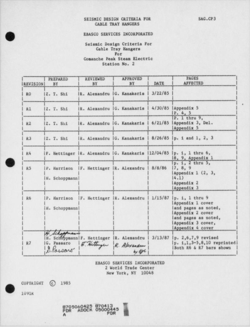
SEISMIC DESIGN CRITERIA FOR SAG.CP3CABLE TEAY HANGERS
!- ESASCO SERVICES INCORPORATED
Seismic Design Criteria Fori Cable Tray Hangers
'ForComanche Peak Steam Electric
j Station No. 2i
IREVISION' BY BY | BY DATE AFFECTED~|| | PAGES| | PREPARED 1 REVIEWED l APPROVED |
.!|,
| | | | |
; .| 10 lZ. T. Shi |R. Alexandru |G. raankaris | 3/22/85 | | i
| |! 1 I'
'
I I l li i I. i'
; | R1 lZ. T. Shi |R. Alexandru :lG. Kanakaris l''4/30/85 || Appendix 5 |
i l | |P. 4. 5 |
| |P. 1 thru 9, |l | 1 |;
,| R2 lZ. T. Shi ||R. Alexandru |G. Kanakaris | 6/21/85 | Appendix 3, Del. |
1 | | Appendiz 5 |,
| l I I I ||
| R3 IZ. T. Shi |R. Alexandru IG. Kanakaris I 8/26/85 |p. i and 1, 2, 3 |
| | | | |
j | | | 1 | , |j i R4 |F. Hettinger |R. Alexandru |G. Kanakaris 112/04/85 |p. i, 1 thru 6, I :
i l l l | |8. 9. Appendix 1 |-'
! I I I I Ip. 1, 2 thru 5, |i | R5 |P. Harrison |F. Hettinger |R. Alexandru | 8/8/86 |7,8,9 | ;
I | | | | | Appendix 1 (2, 3, | !
| |H. Schoppaanal | | |4.1) |
| | | | | | Appendix 2 |
| | Appendix 3 |'
.
| | | . I I | I
| | R6 |P. Harrison |F. Hettinger |R. Alexandru | 1/15/87 |p. i, 1 thru 9 |
| | | | | | | Appendix 1 cover | :
! | |H. Schoppaanal | | land pages as noted, | ;
| | | | | | | Appendix 2 cover | !
| | | | | |and pages as noted, |!
! | | | | | | Appendix 3 cover, | |
| | Appendix 4 cover |.,
|v
' 1 1 1
q'. LA " ~ 1ScMpeannlF.HettingerllR.AlexandruI3/13/87p. 2,6,7,9 revised I !i | H
| |p. 1,1,3-5,8,10 reprintedli i| | R7 |G. Paesaro l p* " ~f 1, lg* j gI' | |Both R6 & A7 bars shown| s
! ,
i ERASCO SERVICES INCORPORATED i
| 2 World Trade Center *
} New York, NY 10048 t
|
COPYRIGHT @ 1985|- 1091R
kD A 45l A PM M| '
!|. . .
.
.--_~.-_.~..--.v . .._ . . _ - . - . . . . . . - . . -.. -- .- . -
.
SEISMIC DESIGN CRITERIA FOR SAG.CP3CARLE TRAY HANGERS '
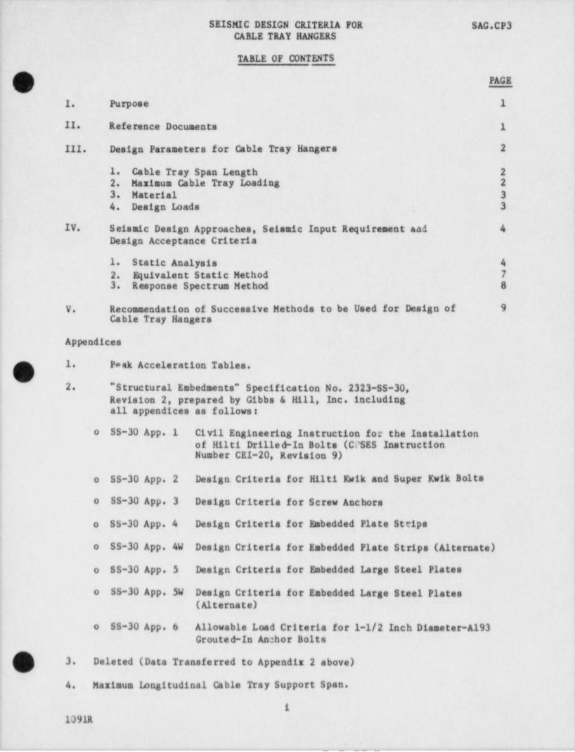
TABLE OF CONTENTS
O -4
j' I. Purpose 1
II. . Reference Documents 1
: III. Design Parameters for Cable Tray Hangers 2
1. Cable Tray Span Length 22. Maximus Cable Tray Imading 23. Material 3 -h
j 4. Design Loads ; 3 |
! IV. Seismic Design Approaches, Seismic Input Requirement and 4Design Acceptance Criteria
,
1. Static Analysis 42. Equivalent Static Method 73. Response Spectrum Method 8
|
i V. Recommendation of Successive Methods 'to be Used for Design of 9Cable Tray Hangers
Appendices ,
t
1. Paak Acceleration Tables.O ~
4
j 2. " Structural Embedmonts" Specification No. 2323-SS-30, |Revision 2, prepared by Gibbs & Hill, Inc. including.
.
; all appendices as follows: '
I l
i o SS-30 App. 1 Civil Engineering Instruction for the Installation ,
| of Hilti Drillee-In Bolts (CPSES Instruction ,
Number CEl-20, Revision 9)
; o SS-30 App. 2 Design Criteria for Hilti Kwik and Super Kwik Bolts.I
l o SS-30 App. 3 Design Criteria for Screw Anchors
o SS-30 App. 4 Design Criteria for Babedded Plate Strips ,
o SS-30 App. 4W Design Criteria for Embedded Plate Strips (Alternate)
j o SS-30 App. 5 Design Criteria for Embedded Large Steel Platesi
o SS-30 App. SW Design criteria for Embedded Large Steel Plates,
! (Alternate),
o SS-30 App. 6 Allowable Load Criteria for 1-1/2 Inch Diameter-A193I Grouted-In An: hor Bolts
3. Deleted (Data Transferred to Appendix 2 above)
f 4. Maximum longitudinal Cable Tray Support Span.i
| 1
: 1091R
i
_ .- _... _ _ .._,,1..-, - .. m .. . ,, . - _ , , _ _ _ . - _ _ . .-,_.~.~m. , -.-__.-,.._--m__.._-,--.......,_,,~,_,-_,__,,-.m...,....,--
-_ _ . . .. - - - .. - . - .- - - - - - . . . .. - -..-- - . - - - . --
1 .
. ..
-SEISMIC DESIGN CRITERIA FOR SAG.CP3CABLE TRAY HANGERS -*
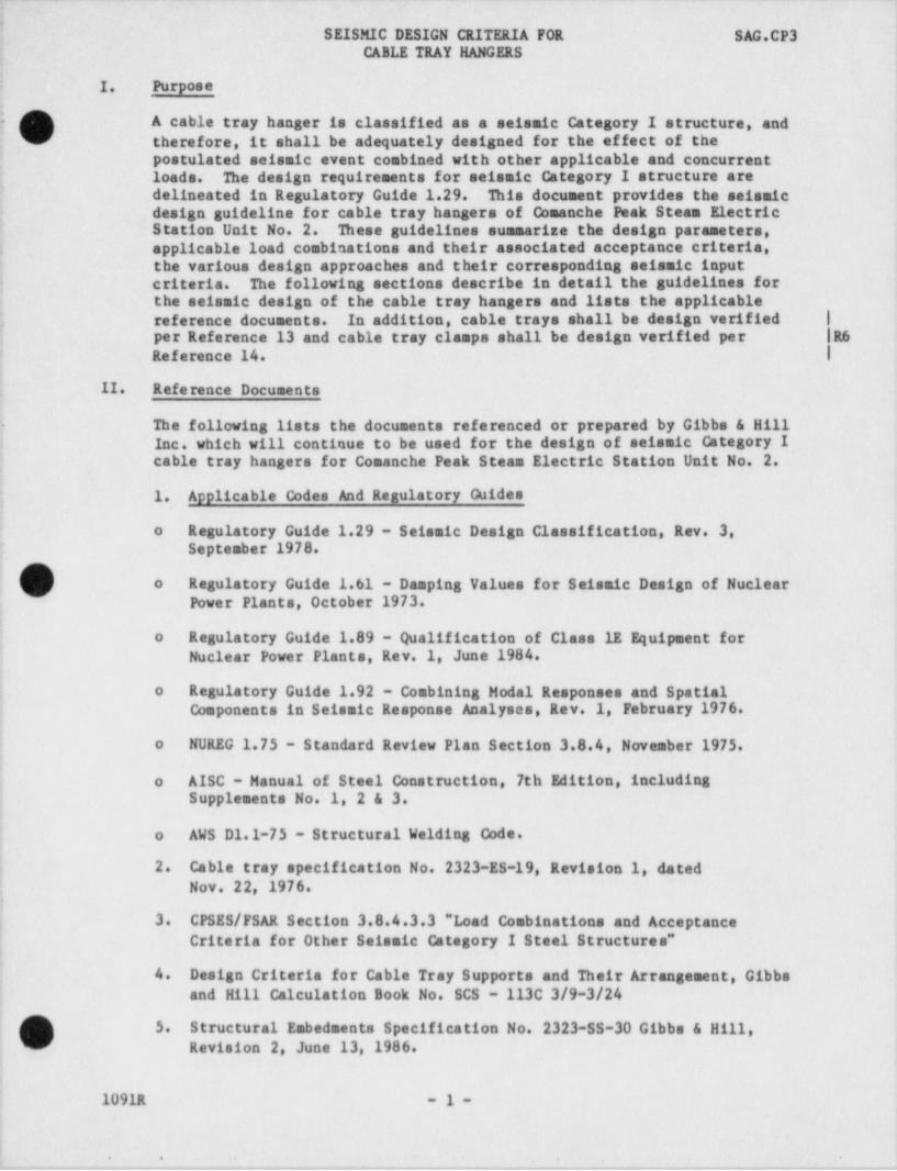
I Pu' poseI. r
f A cable tray hanger is classified as a seismic Category I structure, and_
therefore, it shall be adequately designed for the effect of the1
| postulated seismic event combined with other applicable and' concurrent t
| loads. The design requirements for seismic Category I structure are- delineated in Regulatory Guide 1.29. This docussat provides the seismic
t design guideline for cable tray hangers of Comanche Peak Steam Riectric: Station Unit No. 2. These guidelines summarise the design parameters, |
! applicable load combinations and their associated acceptance criteria, 1the various design approaches and their corresponding seismic input i
t. criteria. The following sections describe in detail the guidelines for ,
j the seismic design of the cable tray hangers and lists the applicable; reference documents. In addition, cable trays shall be design verified |j per Reference 13 and cable tray clamps shall be design verified per |R61 Reference 14. |i
[ -II. Reference Documents ,
l
) The following lists the documents referenced or prepared by Gibbs & Hillj Inc. which will continue to be used for the design of seismic Category Ij cable tray hangers for Comanche Peak Steam Electric Station Unit No. 2..
{ 1. Applicable Codes And Regulatory Guidesj
i o Regulatory Guide 1.29 - Seismic Design Classification, Rev. 3,j September 1978.
o Regulatory Guide 1.61 - Damping Values for Seismic Design of NuclearPower Plants, October 1973.
;
! !
! o Regulatory Guide 1.89 - Qualification of Class 1E Equipment for} Nuclear Power . Plants, Rev.' 1, June 1984. !
I
i o Regulatory Guide 1.92 - Combining Modal Responses and Spatialj Components in Seismic Response Analyses, Rev.1 February 1976...it o NUREG 1.75 - Standard Review Plan Section 3.8.4, November 1975.t
| o AISC - Manual of Steel Construction, 7th Edition, includingj Supplements No. 1, 2 & 3.!
| o AWS D1.1-75 - Structural Welding Code. '
i ,
| 2. Cable tray specification No. 2323-RS-19, Revision 1, dated,
! Nov. 22, 1976. ;Ij 3. CPSES/FSAR Section 3.8.4.3.3 " Load Combinations and Acceptance! Criteria for Other Seismic Category I Steel Structures" '
i- ,
[ 4. Design Criteria for Cable Tray Supports and Their Arrangement, Gibbsand Hill Calculation Book No. SCS - 113C 3/9-3/24
,
i
| 5. Structural Embedaents Specification No. 2323-55-30 Gibbs & Hill,! Revision' 2 June 13,1986.
|i
| 1091R -1-
;'
- - - -. . . 2-
.- - .- - . . - - _ _ - . , - .- .- - _ _ . - - . - . .- --
SEISMIC DESIGN CRITERIA FOR ~ SAG.CP3 |,
CABLE TRAY HANGRS |l
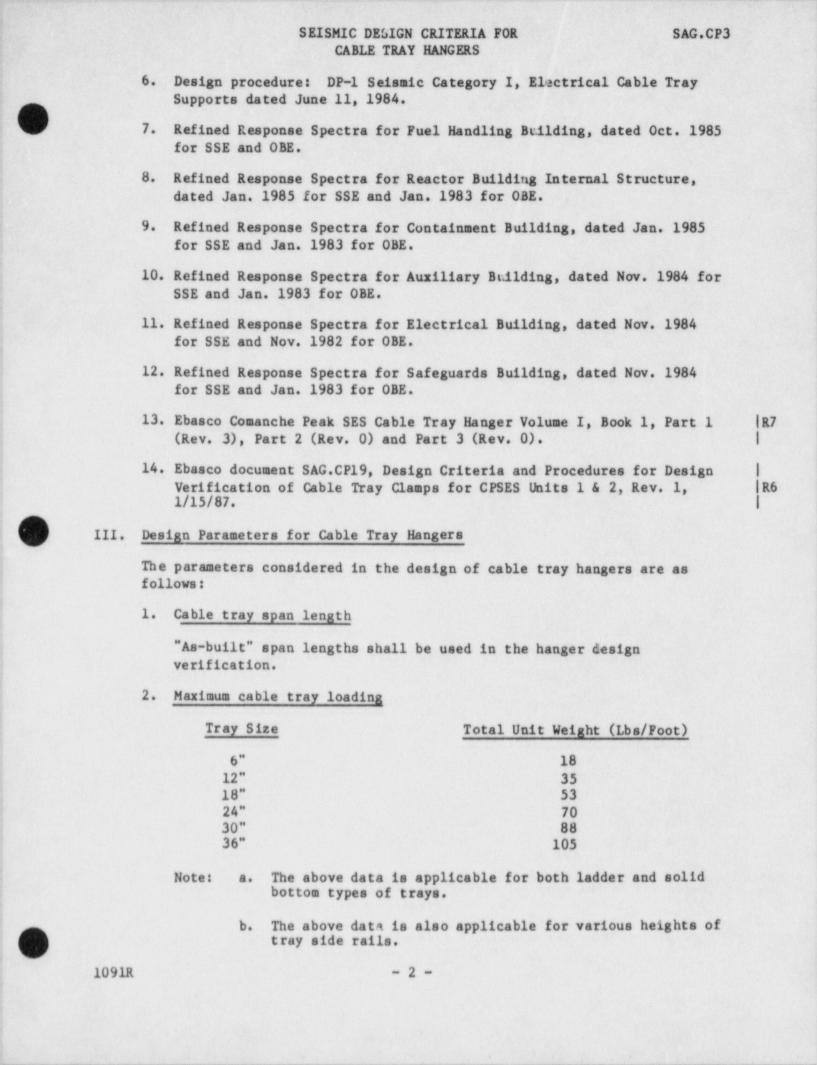
; _6.. Design procedures DP-1 Seismic Category I, Electrical Cable Tray ;
Supporte dated June 11, 1984.
|O 7. Refined Response Spectra for Fuel Handling Building, dated 'Oct.1985.
for SSE and OBE.:
.
8. Refined Response Spectra for Reactor Building Internal Structure,dated Jan'.1985 for SSE and Jan.1983 for OBE.
i 9. Refined Response Spectra for Containment Building, . dated Jan.1985| for SSE and Jan.1983 for OBE. |
I-; 10. ' Refined Response Spectra for Auxiliary Building, dated Nov. -1984~ for -| SSE and Jan.1983 for OBE. I
1
| 11. Refined Response Spectra for Electrical Building, dated Nov.1984j for SSE and Nov.1982 for OBE.Ii 12. Refined Response Spectra for Safeguards Building, dated Nov.1984i for SSE and Jan.1983 for OBE.3
'13. Ebasco Comanche Peak SES Cable Tray Hanger Volume I, Book 1, Part 1 |R7; (Rev. 3), Part 2 (Rev. 0) and Part 3 (Rev. 0). |
|i 14. Ebasco document SAG.CP19, Design Criteria and Procedures for Design |'
Verification of Cable Tray Clamps for CPSES Units 1 & 2, Rev.1, |R61/15/87. |
III. Desian Parameters for Cable Tray Hangers
The parameters considered in the design of cable tray hangers are as,{| follows:
! 1. Cable tray span lenathia
j "As-built" span lengths shall be used in the hanger designj verification.z
} 2. Mariaua cable tray loadinai
| Tray Size Total Unit Weiaht (Lbs/Poot)Ij 6" 18 ,
d 12" 35 I; 18" 53i 24" 70| 30" 88! 36" 105
Notes a. The above data is applicable for both ladder and solidj bottom types of trays.
f b. The above data is also applicable for various heights oftray side rails.
i -1091R -2-i!!
|'
.
. ~ . _ _ _ _ _ _ _ . . . . _ . . . . . . __ __ - . _ _ _ _. - _ _ _ _ _ _ _ _ _ _
SEISMIC DESIGN CRITERIA FOR ~ SAG.CP3-CABLE TRAY HANGERS
c. The above unit weight includes cable,' tray, tray cover
and side rail extension.
d. The above unit weight does not include fire proofingmaterial weight (Thermolag and Thernoblanket).
e. For trays which are fire proofed, the unit weight of j
cable tray including the weight of fireproofing to be ,
used is in the " General Instructions For Cable Tray i
Hanger Analysis". |,
f. All cable tray hangers shall be design verified based on | l"as-built" drawings (ie. hanger members, connection and - |R6-
'
anchorage details). |
g. All cable tray hanger components (members,' connectionsbase angles, base plates and anchor bolts) shall be idesign verified.
'
3. Material |,
|
a. Support structure is ASTM A36Ib. Expansion anchors are Hilti Kwik and Super Kwik Drilled-in bolts-
c. Screw anchors are Richmond insertsd. Embedded plates (strip and area plates) are ASTM A36 |
4. Design loads
The cable tray hangers shall be designed for the following loads andload combinations:
a. Load definitions
Normal loads, which are those loads encountered during normalplant operation and shutdown, include
D Dead loads and their related soments and forces.-
-|Live load equals zero. |R6L -
To - Thermal effects and loads during norest operating or |
shutdown conditions, based on the most critical
transient or steady state condition.*
Severe environmental load includes:
F,qo - Loads generated by the operating basis earthquake R6including secondary wall displacement effects.
Except for anchorage components, accident temperatures (Ta) -|*
are not considered in design verification per CPSES FSAR (Pg.3.8-83 and 3.8-110). Accident thermal loads on anchorages areconsidered generically by studies. Furthermore, per AISC |R6
O Manual of Steel Construction (Ps. 6-9), no reductions in F Iyare required for temperatures up to 700'F. |
1091R -3-
.. . . .
, - - _ -. . . . . -. . . _ - ___ _ _ . _ _ _- - -__- _ - -
SEISMIC DESIGN CRITERIA FOR SAG.CP34
CABLE TRAY HANGERS
Extreme environmental loed includes:3
F,q, - Loads generated by the safe shutdown earthquake |R6ig - including secondary wall displacement effects. |s
} b. Load combinations l|
The following load combinations shall'be considered in design ofcable tray hangers:-
1.D + L + F,q+o = S 1.5S-
F,q, = 1.6SD + L + Toii.
iii. D + L + To + F,q, a,
i
where S is the required strength based on elastic designi
methods and the allowable stresses defined in Part 1 of the'
.AISC " Specification for the Design, Fabrication, and,
!. Erection of Structural Steel for Buildings" (published in1 the Manur.1 of Steel Construction, seventh edition). In no
for n R6case shall allowable stress exceed 0.90 F[ esses.ormaltensile stresses and 0.50 F for shear stt y
IV. Seismic Design Approaches, Seismic Input Requirement, and DesignAcceptance Criteria.
There are several analytical methods available which will.be used indesign or design verification of cable tray hangers. Because the level
! of sophistication is not the same for each method, the seismic input!' requirement must vary 'in order to compensate for whatever the method
lacks in sophistication, and therefore the conservatism of results
associated with each analysis method also varies.ij For span layouts not in conformance with Appendiz 4 of this design
criteria, design verification may be performed by the Response Spectrum] Method (Section IV.3) or, if appropriate, by the Equivalent Static; Method (Section IV.2) per Attachment Y of the General Instructions.
] The following procedures describe the three (3) most acceptablemethods: static analysis, equivalent static method and response'
spectrum method. The seismic input criteria for each analysis method is'
also' addressed.!
! IV.1 STATIC ANALYSISl: a. Finite Element Model.
A 3-D model shall be prepared to represent cable tray hangers. An <
offset or eccentricity due to the assemblage of various types ofstructural members and/or transmission of loads shall be considered
,in the preparation of the computer model.
Boundary conditions at anchorage points shall properly represent |R6! the actual anchorage condition. | )i O
1091R -4-|i
!'
,
y__ _ _ . . . _ _ , , 2,....., _...-,_..7._.__y_L__,_..__._-__,_...,,.,__.y ,...L.,.__.. _.-__,._,.m,,_-. , , , , . . .' ..,_h__,,___
_ _ _ _ _ . _ - _ - _ _
SgISMIC DESIGN CRITERIA FOR SAG.CP3CABLE TRAY HANGERS
b. Cable Tray Loading
The total cable tray loading for each run shall be calculated based
on the size of tray and the actual tray span lengths which are shownon the support drawing.
The cable tray loading shall be lumped as a nodal weight at theactual location on the tier and, if not known, at such a location on ~ j
the tier that it will induce the worst member stress responses andthe maximum anchorage reactions.
c. Seismic Input "a" Values
For a static analysis the peak spectral "g" values from the 4%damping OBE curves and the 7% damping SSE curves which were l
generated at the mounting locations of cable tray hangers shall beused multiplied by a coefficient to account for multimode response.These peak spectral "3" values for various buildings and differentfloor elevations can be found in the Appendix 1. For the case wherethe hangers were supported off the wall, the envelope of the theresponse spectrum curves for the floor immediately above and below R6
the hanger location shall be used. The required seismic design "3" lvalues in three . (3) orthogonal directions are 1.25 (multimoderesponse multiplier-MRM) times the peak spectral "a" values.
d. Static nalysis
O The seismic load effect on the cable tray hangers will treated asa static load. She dynamic effect from both seismic event andresponse characteristics of support structure are conservativelyconsidered by using the 1.25 times the peak spectral "g" value as aninput. However, for transverse type cantilever and trapese cabletray hangers, the seismic load effect due to the hanger'sself-weight in the longitudinal direction (direction parallel totray run) shall be determined by multiplying the spectral "g" valuecorresponding to the CTH fundamental (lowest) longitudinal frequencyby 1.25 regardless of whether that frequency is to the lef t or rightof the peak response frequency.
If the cable tray hanger is attached to a steel structure, use 1.5times the peak spectral "g" value and a fixed base boundarycondition.
The static analysis shall be performed for the following load cases|. individually:
1) Dead load1
ii) Seismic load in vertical direction
iii) Seismic load in transverse direction
iv) Seismic load in longitudinal direction,
1091R -5-
p 4. . . . . . .. .
..._ . . . ,
. . . i: ..
__ . - _ _ _ _. . __ _ _ _ __ _
SEISMIC DESIGN CRITERIA FOR SAG.CP3- CABLE TRAY HANGERS
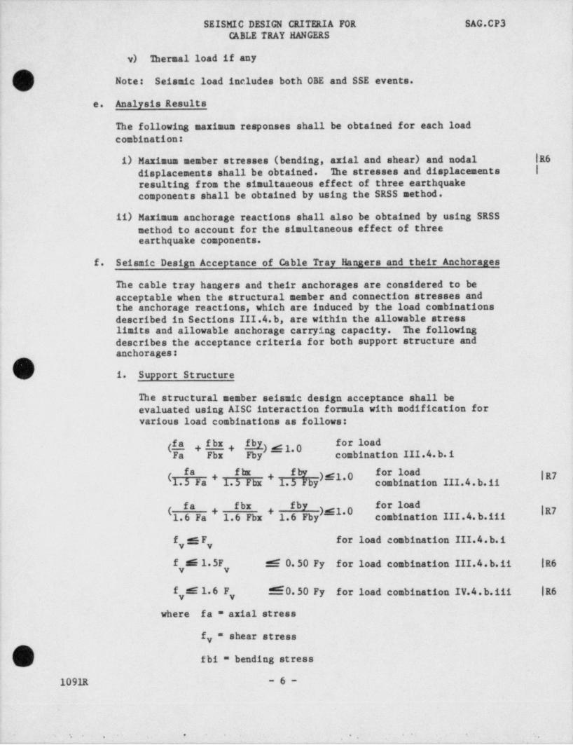
! v) hermal load if any .
. Note: Seismic load includes both OBE and SSE events.
e. Analysis Results
The following maximum responses shall be obtained for each loadcombination:'
'
i) Maximum member stresses (bending, axial and shear) and nodal |R6 i
-displacements shall be obtained. 3he stresses and displacements |
resulting from the simultaneous effect of three earthquake<
components shall be obtained by using the SRSS method.
ii) Maximum anchorage reactions shall also be obtained by using SRSSsethod to account for the simultaneous effect of three
'' earthquake components.
f. Seismic Design Acceptance of Cable Tray Hanaers and their Anchoranes
The cable tray hangers and their anchorages are considered to'be.
acceptable when the structural member and connection stresses andthe anchorage reactions, which are induced by the load combinationsdescribed in Sections III.4.b, are within'the allowable stress
,
limits and allowable anchorage carrying capacity. The followingdescribes the acceptance criteria for both support structure and
,
anchorages:,
1. Support Structure
The structural member seismic design acceptance shall be;
evaluated using AISC interaction formula with modification forvarious load combinations as follows:
Y f r load(S* + I * + Fby).4 1.0 combination III.4.b.iFa Fbx
I* N fE f'' l'*d |R7(1.5 Fa + 1 5 Fbx + 1.5 Fby)sfl.0 combination III.4.b.ii
'
fa fbx fby '# *|R7(1.6 Fa , 1.6 Fbr ,1.6 Fby)d l.0 combination III.4.b.iii
,
fC for -load combination III.4.b.i 'y y
| f n 1.5F _d O.50 Fy for load combination III.4.b.ii- |R6y y
f sEE1.6 F f.60.50 Fy for load combination IV.4.b.iii |R6.y y
where fa = axial stress
f = shear stressy
fbi = bending stress
1091R -6-:
.
* t*,
*' 5 .' . . ,

. _ _ _ _ -
SEISMIC DESIGN CRITERIA FOR SAG.CP3CABLE TRAY HANGERS
'~
(\Fa, Fbi and F = allowable stresses for axial,.y
bending and shear stress, perAISC 7th edition. In all caseseach individual denominator above Ifor load combinations III.4.b.1, |R711, and iii shall be less than |0.9Fy. |
ii. Anchorage (anchors)
o Kwik-bolt and Super Kwik-bolt.
The design criteria and allowable loads for above driven-inbolts are tabulated in Appendix 2.
|
o Screw Anchors.
IThe design criteria and allowable loads for screw anchorsare contained in Appendix 2. When a redline drawing doesnot identify the bolt / thread rod material in a Richmond |Insert, A-36 material shall be assumed in the cable tray j
hanger design verification.
Note 1. The allowable loads for Hilti expansion anchors forthe load combination involving OBE are the load
f-~ capacities corresponding to a safety factor of 5,
( and for the load combination involving SSE are theload capacities corresponding to a safety factor of4.
2. The safety factors for Richmond Anchors are 3.0 for- |R6both OBE and SSE. |
3. Prying action on anchor bolt, if any, shall beincluded. The effects of the flexibility of thebase plate on the anchor bolt shall be considered.
I 4. For floor-mounted CTHs in building areas withconcrete topping, the actual anchor bolt embedded.length (as determined from the redline drawing)shall be reduced by two inches (2") to account forthe topping.
IV.2 EQUIVALENT STATIC METHOD
a. Finite Element Model
See Section IV.1.a
b. Cable Tray Loading
() See Section IV.l.b
1091R -7-
- , 1.
- - - _ . .
. . .. . . .
|'SEISMIC DESIGN CRITERIA FOR SAG.CP3
CABLE TRAY HANGERS '
I
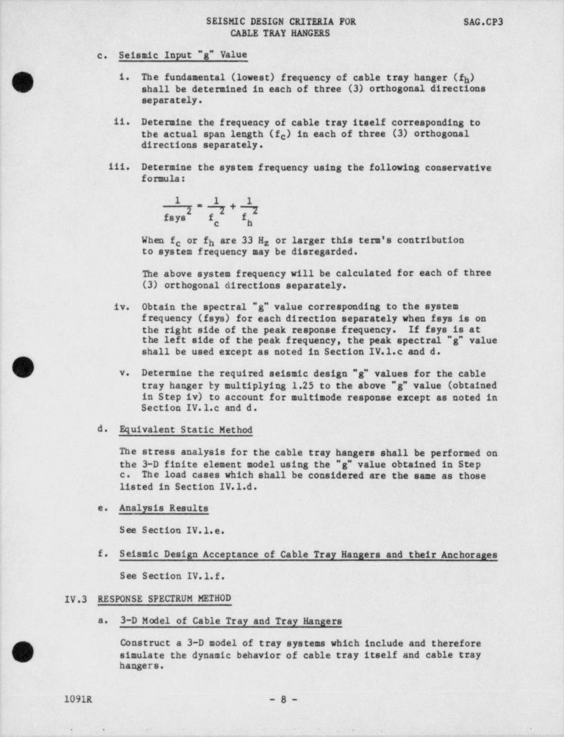
c. Seismic Input "g" Value
Q i. The' fundamental (lowest) frequency.cf cable tray hanger (f ) 1h\/ shall be determined in each of three (3) orthogonal directions
separately.
.ii. Determine the frequency of cable tray itself corresponding tothe actual span length (fe) in each of three (3) orthogonal' directions separately.
iii. Determine the system frequency using the following conservativeformula: ;
1 1 12"7+7
fsys f f*
c h
When f or fh are 33 Hz or larger this tern's' contributioncto system frequency may be disregarded.-
;
The above system frequency will be calculated for each of three(3) orthogonal directions -separately.
iv. Obtain the spectral "g".value corresponding to the systemf requency (fsys) for each direction separately when fsys is _onthe right side of the peak response frequency. If fsys is atthe left side of the peak frequency,-the peak spectral "g".value
'shall be used except as noted in Section IV.1.c and d.
v. Determine the required seismic design "g" values-for the cabletray hanger by multiplying 1.25 to the above "g" value (obtained
;
in Step iv) to account for multimode response except as noted in- '
Section IV.1.c and d. !
d. Equivalent Static Method
The stress analysis for the cable tray hangers shall be performed onthe 3-D finite element model using the '"g" value obtained in Stepc. The load cases which shall be considered are the same as those - |
listed in Section IV.l.d.1
e. Analysis Results
See Section IV.1.e. ]i
f. Seismic Design Acceptance of Cable Tray Hanaers and their Anchoranes-
See Section IV.l.f.
IV.3 RESPONSE SPECTRUM METHOD
a. 3-D Model of Cable Tray and Tray Hangers
' Construct a 3-D model of tray systems which include and. therefore'
simulate the dynamic behavior of cable tray itself 'and cable tray
; hangers.
-il
1091R -8-
* | - - - --. . . . . ._ . _ . . ' -- . . , . .
' ' *
. . . . ..
SEISMIC DESIGN CRITERIA FOR SAG.CP3CABLE TRAY HANGERS
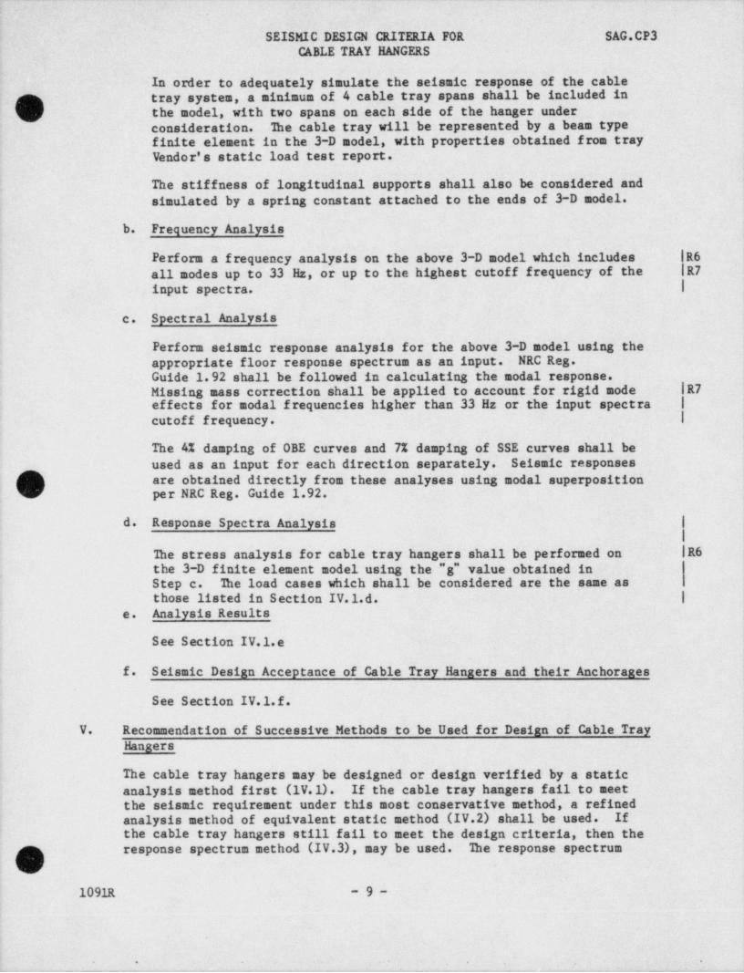
In order to adequately simulate the seismic response of the cabletray system, a minimum of 4. cable tray spans shall be included in
Os the model, with two spans on each side of the hanger underconsideration. The cable tray will be represented by a beam typefinite element in the 3-D model, with properties obtained f rom trayVendor's static load test report.
The stiffness of longitudinal' supports shall also be considered and'
simulated by a spring constant attached to the ends of 3-D model.' b. Frequency Analysis
Perform a f requency analysis on the above 3-D model which includes - R6
all modes up to 33 Hz, or 'up to the highest cutoff frequency of the R7
input spectra. I
c. Spectral Analysis
Perform seismic response analysis for the above 3-D model using theappropriate floor response spectrum as an input. - NRC Reg. --
Guide 1.92 shall be followed in calculating the modal response.Missing mass correction shall be applied to account for rigid mode- |R7effects for modal f requencies higher than~ 33 Hz or the input spectra |
cutoff frequency. I4
,
The 4% damping of OBE curves and 7% damping of SSE curves shall beused as an input for each direction separately. Seismic responses
. are obtained directly from these analyses using modal superposition
] per NRC Reg. Guide 1.92.I
d. Response Spectra Analysis,
The stress analysis for cable tray hangers shall'be performed on |R6the 3-D finite element model using the "g" value obtained in
,
Step c. The load cases which shall be considered are the same as; those listed in Section IV.1.d. I
e. Analysis Results ;
See Section IV.1.e
f. Seismic Design Acceptance of Cable Tray Hanaers and their Anchorages -|
See Section IV.1.f.
V. Recommendation of Successive Methods to be Used for Design of Cable Tray
Hangers
The cable tray hangers may be designed or design verified by a staticanalysis method first (1V.1).- If the cable tray hangers fail to meetthe seismic requirement under this most conservative method,.a refinedanalysis method of equivalent static method (IV.2) shall be used. . Ifthe cable tray hangers still fail to meet the design criteria, then the'
response spectrum method (IV.3), may be used. The response spectrumO1091R -9-
'' * *'
. _ , --. .

3 ~ .- - _ _ - - - - - -
SEISMIC DESIGN CRITERIA FOR SAG.CP3CABLE TRAY HANGERS
method approach simulates better the dynamic behavior of the cable traysystem under the effect of the postulated seismic event and thus mayproduce seismic responses of the structural system closer to reality.e
; Therefore, by response spectrum sethod, the conservatism associated withthe seismic response obtained from static analysis and equivalent staticmethod can be reduced to a minimum. In conclusion, if the cable trayhangers still fail to pass the acceptance criteria by a spectralresponse analysis, a much more refined analysis such as a time historyanalysis method can be used. A procedure for such analyses will begiven, should the need arise.
O
.
|
O1091R - 10 -
*- '
_ . _ -

. . - ,_ _ n - , . - . , . _ 7 - , . - . ,,- - , , . , .. -
_ . . _. . ..-.. . . . .
- . . _'"Q , '.,
,
** _ * -| |-' ~ - - - ' > ~ L'Y'< -' ' ' ~ ' '*
K^ . J. , - <,
>^
,' !:;:s : .;;; ~ L :% =c... _.
,1 ,
4
. _ . .
I. , |- .
. ., - - -, ,
n - ;.i.
x; - , Ebasco " General Instructions For (|'P- .
' '~ '
L" * * Cable Tray Hanger Analysis For -j.
'<
,
Comanche Peak Steam Electric Station| -4
V No. I and 2", (Replace pages - cover
j? -
-
< page, x. 1, 1.1, 2 thru 6, 6.1, 7 thru~
13.1, 36, 36.1, 36.2, 158, 160, 169.3 ._..
'
.
-;c , thru 169.9 187 in Reference 36)-
, +_
F
'r^'
, , oi
+|'
j .. -
~
e
, 6
- '( ,
)~ '
'
<-\,-
..'U.
+- 2
'
>; .
*
, , .
.
74
/ T
4
?s- ' e
4..t
$' , a * ' *
; .
,'(' r j }
. -
4
.
,
.
.I
d
y
[ |
<4 s. [
[ L
b. -j _.,
y
i
i
-
tr
.g.-
,r.
- E
a z,
#1
r
g w
+
e <
- - - - .
ar
s y,- -
4ae
. / 4
<
; O '
.
.
!e
a ,s,,.y - ' - '' ~ **
- - _.. , ~-
'.
A.. y
i. - v .- ,
f ? -r- - - - - -' e' - m h - - e - t 1 e v ,e%,--m.. .-,-m.,,- - [., -, r ,.,e., g. 4 y . . . , , , , , , , ._y ,,_..w ,, y,.,_.g,_ y _y , y.