seismic design evaluation guidelines for buried piping …
TRANSCRIPT

Od^-^son^o-^sr BNL-61711
SEISMIC DESIGN EVALUATION GUIDELINES FOR BURIED PIPING FOR THE DOE HLW FACILITIES1
Chi-Wen Lin Consultant, Martinez, CA
George Antaki Westinghouse Savannah River Co., Aiken, SC
Spencer H. Bush Review & Synthesis Assoc, Richland, WA
Carl Costantino City Univ. of New York, New York, NY
Kamal Bandyopadhyay Brookhaven National Lab., Upton, NY
Robert Kennedy RPK Structural Mechanics Consultant, Yorba Linda, CA
ABSTRACT NOMENCLATURE
This paper presents the seismic design and evaluation guidelines for underground piping for the Department of Energy (DOE) High-Level-Waste (HLW) Facilities. The underground piping includes both single and double containment steel pipes and concrete pipes with steel lining, with particular emphasis on the double containment piping.
The design and evaluation guidelines presented in this paper follow the generally accepted beam-on-elastic-foundation analysis principle and the inertial response calculation method, respectively, for piping directly in contact with the soil or contained in a jacket. A standard analysis procedure is described along with the discussion of factors deemed to be significant for the design of the underground piping.
The following key considerations are addressed: 1. the design feature and safety requirements for the inner (core) pipe and the outer pipe, 2. the effect of soil strain and wave passage, 3. assimilation of the necessary seismic and soil data, 4. inertial response calculation for the inner pipe, 5. determination of support anchor movement loads, 6. combination of design loads, and 7. code comparison. Specifications and justifications of the key parameters used, stress components to be calculated and the allowable stress and strain limits for code evaluation are presented.
Finally, a numerical example is provided to illustrate the application of the guidelines.
C D H i P PGA
PGD PGV R S B „ B 2
C. E. E.
K 0
K. L
M„
pipe cross-sectional area, net after the corrosion allowance apparent wave velocity traversing the site pipe diameter depth to the top of the pipe stress intensity factor internal pressure peak ground acceleration of the seismic wave peak ground displacement peak ground velocity pipe radius Code allowable stress value primary stress indices soil adhesion (units of stress) Young's modulus of the soil Young's modulus of the pipe material the secant modulus of elasticity of the buried pipe maximum friction force/unit length of pipe axial force from thermal expansion axial force from both anchor movement and wave passage the frequency (in Hz) at the peak spectral velocity coefficient of soil earth pressure at rest modulus of subgrade reaction moment of inertia of the pipe cross section the dominant wave length of the passing seismic wave resultant moment from sustained loads resultant moment (use only one-half the moment range from earthquake) from occasional loads
This study was sponsored by the U. S. Department of Energy, Office of Environmental Restoration and Waste Management (DOE-EM).
wmmnioN OF THIS DOCUMENT IS WMITTH> 8 S

M,
M, DISP
M D W ,M, deadweight and earthquake inertia response moment (use only one-half the moment range from earthquake), respectively range of resultant moment from thermal expansion resultant from seismic loads due to both anchor movement as well as wave passage, use half the range moment due to wave passage moment due to oscillatory SAM bearing capacity factor expansion stress bending stress (one-half the range) allowable stress at temperature torsional Stress (one-half the range) stresses due to occasional loads and sustained loads material yield stress nominal pipe thickness the apparent wave speed of the seismic motion weight of pipe and its contents wave Coefficient, 1 for compression or Raylcigh wave, 2 for shear wave the Poisson's ratio for soil axial strain total strain of the pipe backfill weight density apparent angle of pipe wall friction (degrees) average contact pressure between soil and the pipe due to soil weight and surcharge loadings
M„ M 0
N » S. S b
s„ s, s.
t, v.
w, a 6
o
St
Y •.
1. INTRODUCTION
Underground piping for the DOE HLW facilities is normally encased (or double containment) piping system, i.e., consists of a "pipe in a pipe" arrangement. The inner (or core) pipe is designed to convey waste and is intended to remain leak tight for all design loads, including seismic loads. The outer pipe is designed to provide additional assurance that the waste carried by the core pipe will be contained, in the unlikely event of leakage from the core pipe.
There are many possible design combinations of the encased underground piping. For instance, the outer pipe could be steel, ceramic tile, or concrete. The outer pipe could also be either in direct contact with the supporting soil, or supported and housed in underground concrete trenches.
Piping which is in direct contact with the soil is confined by soil and controlled by soil movements
during a seismic event. Because it is continuously supported by soil, the inertial response of the buried outer piping is rarely significant. Instead, its stress and strain are more significantly controlled by the soil strain from ground motion. The beam-on-elastic-foundation principle (Reference 1) is generally used to calculate the response of the outer pipe.
On the other hand, the inner piping (and also the outer piping when it is not in direct contact with the soil) is expected to behave in many ways similarly to above ground piping. The inertial response could become a significant factor in this case, and the finite element response calculation method can be employed.
There are currently no industry codes or standards which provide necessary guidance for the analysis of the buried double containment piping where both piping inertial effects and the effects of soil strains are present. Chapter 7 of Reference 2, fulfills such a need.
This paper presents a summary discussion of the methods, procedures, and criteria recommended in Reference 2 for buried piping and conduits.
2. CONTROLLING FACTORS FOR THE ANALYSIS OF BURIED PIPING
The inertial response analysis method adopted for the above ground piping is not entirely suitable even for the analysis of the inner piping when it behaves fairly similar to the above ground piping, because of the presence of the outer pipe. On the other hand, the beam-on-elastic-foundation analysis approach traditionally employed for the close-formed static analysis of the single-walled buried piping needs to be modified when a computer aided finite element analysis is desired.
Table 1 presents a comparison of some of the more important factors affecting the design evaluations of various piping arrangements for the buried piping. The guidelines provided in Reference 2 and discussed in detail in this paper are intended to ensure that the key factors affecting the design evaluation of the buried piping are properly addressed.
3. REQUmED SEISMIC AND SOIL DATA
Appropriate seismic and soil data must be assembled to allow for evaluation of the maximum response

DISCLAIMER
This report was prepared as an account of work sponsored by an agency of the United States Government. Neither the United States Government nor any agency thereof, nor any of their employees, make any warranty, express or implied, or assumes any legal liability or responsibility for the accuracy, completeness, or usefulness of any information, apparatus, product, or process disclosed, or represents that its use would not infringe privately owned rights. Reference herein to any specific commercial product, process, or service by trade name, trademark, manufacturer, or otherwise does not necessarily constitute or imply its endorsement, recommendation, or favoring by the United States Government or any agency thereof. The views and opinions of authors expressed herein do not necessarily state or reflect those of the United States Government or any agency thereof.

DISCLAIMER
Portions of this document may be illegible in electronic image products. Images are produced from the best available original document.

loadings of the underground facilities. The seismic environment must include estimates of peak ground acceleration (PGA), peak ground velocity (PGV), and peak ground displacement (PGD) defined at the ground surface appropriate for the hazard specification.
Sufficient data should be gathered to suitably identify the foundation soil surrounding the underground components and determine their appropriate parameters. These can be gathered using standard methods of foundation investigation, namely, standard penetration tests (SPT), cone penetrometer testing, seismic reflection surveys, crosshole, uphole and/or downhole geophysical testing. Regulatory Guides 1.132 and 1.138 (References 3 and 4, respectively) present recommendations for geotechnical investigations and laboratory testing. Such investigations must also suitably define changes of soil properties along the route of the underground facilities.
Soil properties of specific interest include:
• grain size distribution description • plasticity characteristics • density and relative density • equivalent SPT blow count information • effective coefficient of subgrade reaction
liquefaction potential • equivalent cyclic properties obtained from
either site specific laboratory testing or generic data for appropriate soil types
Enough data must be available to allow for evaluation of the effect of seismically induced pore pressures on ground movements and the loads induced on the underground system from relative movements between the ground and the piping.
A range of generic values may be used with sufficient variability to account for undnowns.
4. DETERMINATION OF KEY INPUT PARAMETERS FOR ANALYSIS
Modulus of Subgrade Reactions
ypically, the buried piping system is analyzed as a series of beam elements on an elastic foundation, requiring the assumption of modulus of subgrade reaction for the soil/pipe system. In a computer analysis, the modulus of subgrade reaction (lbs/in3) is used to determine the soil spring constants at the pipe
and soil interface along the horizontal and vertical directions.
The modulus of subgrade reaction is a simplified concept that has often been used to assess pseudo-static interaction between buried structures and the surrounding soil. Unfortunately, the simple one-parameter coefficient of subgrade reaction (Winkler spring coefficient), even for the ideal case of linear soil stress-strain behavior, does not properly account for shear transfer between adjacent points in the soil. Therefore, approximate comparisons with elastic solutions lead to a stiffness parameter which is a function of both the structural and soil parameters.
For real soils, the stiffness parameter is found to be also related to soil type, depth of burial, direction of loading (horizontal or vertical), and strain level. The representation of this complex interaction with a single parameter has given rise to many recommendations presented in the open literature.
For long straight sections of piping, ground movement induced forces, moments and stresses are found to be relatively insensitive to the specific value of the stiffness parameter, except for the relatively unusual case of piping traversing areas of significantly different soil properties.
However, ground movement induced loads computed at or near pipe bends and structural intersection points can be strongly dependent on the specific value of the modulus. It is therefore important that conservative estimates of this modulus be selected for any analysis. This is typically accomplished by incorporating the effects of variability in this parameter on the computed stress resultants.
It should be noted that, for buried piping analyses, conservative estimates of the subgrade modulus tend to lie on the stiffer side of the range of potential variability. This is different from the normal assumptions of foundation analyses which typically are made to underestimate the stiffness parameter so as to overestimate settlement values.
Due to greater uncertainties associated with the selection of the subgrade modulus, the buried piping analysis performed should incorporate a wider variation in the modulus than is typically used in standard soil-structure interaction analyses so as to lead to bounding estimates of induced loading. Site specific measurements, when available, can be used to reduce the variability in parameter that must be incorporated into the evaluations, since the

*
recommendations for generic soils incorporate such wide variations in the appropriate coefficients.
The form of the reaction-displacement relations required to perform the analysis of buried piping is shown in Figure 1. In each case, the soil reaction to the specified displacement can be approximated by means of a linearly varying relationship to the maximum value defined by the soil strength as well as the piping configuration. The slope of the straight line segment is defined as the modulus of subgrade reaction. For application to simple beam models, the Winkler spring coefficient is then defined as the product of the subgrade modulus and the pipe diameter.
For the case of piping placed near the surface in uniform soils, with a soil cover of at least three diameters, the effective subgrade modulus in the horizontal direction, Kh, can normally be expected to be larger than the vertical modulus, k„ since the resistance of the soil cover above the piping is less effective for resisting displacement. Therefore, if the pipe is buried three or more pipe diameters deep, the horizontal stiffness is recommended to be at least equal to the vertical stiffness, unless special conditions indicate such is not the case.
Limiting Values of Lateral Load
The upper bound values of reaction or yield values of the pressure-displacement curves of Figure 1 for each displacement mode of interest can be estimated from bearing capacity relations available in the literature, a summary of which is provided in Reference 20. For vertical displacements, the limit on pressure due to upward pipe displacement is controlled by the breakout capacity of the trench material above the pipe. These limiting loads in both the horizontal and vertical directions tend to reduce the computed maximum moments from linear analyses.
Plate Load Testing
Estimates of in-situ stiffness can be obtained from simple field tests using plate loads, although such test results tend to underestimate the stiffness of fully confined soils. In addition, the results quoted from such tests are typically associated with shear strains in the range of 0.1% to 1%, higher than the strains associated with the initial slope of the load displacement curve. The stiffness from these tests can be increased by a factor of about 2 to arrive at results appropriate or the lower strain levels associated with the vibratory problem.
In addition, if the plate load test is conducted, for example, using a 1 foot diameter rigid plate, the slope of the pressure-displacement curve must be suitably modified to account for the difference between the pipe and plate diameter; that is:
K = k., f(D) (1)
where k,, is the coefficient of subgrade reaction for the 1 foot diameter plate and f(D) is a function of the pipe diameter as well as the soil type. For plate tests conducted on the surface of sandy soils, the experimentally determined relationship is found to be:
k. = k., [<D + 1)/(2D)]2 (2)
while for typical cohesive soils, the relationship is
K - k„ [1/D] (3)
Typical values of coefficient of subgrade reaction from plate load tests are listed in Tables 2 and 3.
Analytic Estimates
Several formulas have been used in the past to estimate the modulus of subgrade reactions for the horizontal lateral direction. One of these is Vesic's approximation (Reference 5) in the following form:
k. = 0.65((E.Dy(EpIp))1"2 . (E/O-u, 2)) (4)
The modulus of subgrade reaction is related to Vesic's approximation by:
k, = k,/D (5)
Other forms of modulus of subgrade reaction have also been proposed (e.g., References 6, 20, and 26). For instance, the recommendation in Reference 20 is to define K 0 as follows:
ko=yNqhHD/[0.06(H+D/2)]p (6)
Equation (6) is not a direct function of the pipe rigidity as in the case of Equation (4) but it includes the depth of the pipe below grade (H) as a parameter. Therefore, the modulus of subgrade reactions calculated from Equations (4) and (6) may differ markedly. Hence, care should be exercised when determining the appropriate equation to be used for a particular situation.
Because piping is normally modelled as a concentric (line) model, the spring constant of the soil per unit

length of the pipe is calculated by multiplying the modulus of subgrade reaction with Ihe pipe diameter.
5. ANALYTICAL PROCEDURES AND GENERAL GUIDELINES FOR THE BURIED PIPING
In general, the buried portion of the underground piping can be either analyzed by close-formed beam-on-elastic-foundation formulas or by computerized pseudo static analysis. As for the inner piping encased by the outer piping, its inertial response is typically analyzed by a computer program and carried out on a dynamic modal analysis basis similar to the above ground piping. In what follows, some of the key steps which are generally employed for a complete analysis of the buried piping are discussed in detail.
Seismic Inertial Response Analysis
For the case of a pipe not supported directly by the surrounding soil, the pipe is typically supported intermittently within other piping or support boxes and is free to move transversely within the outer pipe. Longitudinal friction between the inner pipe and its supports will provide some restraining effects due to selfweight of the inner pipe. Otherwise, the response of the inner pipe can be expected to behave as conventional aboveground piping during a seismic event. Dynamic or equivalent static load methods of analysis are applicable to treat such inertial response modes of the pipe (References 7 and 8).
A damping value of 5% is considered appropriate for underground piping. The design response spectra (defined typically as the free-field ground surface spectra) for the three directions of input should be applied and the results combined on a square-root-sum-of-squares (SRSS) basis. In view of the fact that the inner piping is anchored and supported by the outer piping, interaction effects between the two must be addressed.
Beam-on-elastic-foundation Analysis
The methods of analysis for buried piping are based on beam-on-elastic-foundation principle by modelling the piping system as simple beam models supported on linear Winkler springs. These methods are summarized in References 9 through 19. They are in general use throughout the industry and have been keyed to empirical data.
The following loads are normally considered in the buried piping analysis:
• normal operating thermal loads, • normal operating internal pressure loads, • external soil loads, soil settlement loads, and • seismic loads.
Non-seismic Loads
In the simplified beam-on-elastic-foundation approach, pipe stresses due to thermal loads can be calculated similar to the case of seismic loads. The maximum axial strain from temperature expansion along the straight pipe run is first determined and then used to determine pipe stresses at elbows, bends and tees (Reference 20).
For the normal operating internal pressure loads, it can be calculated as in the case of above-ground piping by neglecting the restraints provided by the surrounding soil.
Assessment of external soil loadings can be performed by the standard methods of soil mechanics (References 21 and 22).
Seismic Loads from Transient Ground Movements
For estimating stress resultants due to transient ground displacements from wave passage effects, current practice generally assumes plane wave motion either parallel or transverse (across) to the axis of the pipe.
Axial Differential Ground Movements
Along the axial direction, the maximum axial ground strain is found to be:
( O — = ± (PGV)/(acC) (7)
The peak ground velocity (PGV) is typically defined by the design ground spectrum at the site. The coefficient cc£ is defined as 1 or 2 depending upon whether the traversing wave type is either a compression, Rayleigh, or shear wave. Values of this coefficient for each wave type can be found in Table 4. The parameter C is the apparent wave velocity traversing the site.
The specific value of wave velocity and wave type to be used in any particular situation is in general not clear and must be selected with care. If the buried pipe is located at a depth of 20 feet or more in

ordinary soil, the effect of the Rayleigh wave at these depths can be considered negligible.
For shallow buried systems located at large distances from a potential fault (beyond about 200 km), the effects of Rayleigh waves may predominate. For closer distances to a potential seismic source, body waves are generally the largest contributors to the seismic hazard. In this case, the apparent horizontal wave velocity is often controlled by the deeper and higher velocity material at depth and not by the wave speeds of the soil immediately surrounding the piping system. For vertical motions, however, the local soil wave velocity may dominate.
For a uniform soil site overlying stiff rocks, the free-field ground motion tends to be dominated by shear waves propagating nearly vertically. In this case, the propagation velocity of the seismic wave at the ground surface is strongly influenced by the wave speed in the bedrock below (Reference 23). Based on limited empirical observations (e.g. Reference 16), the use of shear wave velocities in Equation (7) less than about 2000 fps (Reference 7) leads to overly conservative strain estimates,, even for the case of soils having lower values of shear wave velocities.
For vertical runs of pipe, PGV associated with vertical motion should be used in Equation (7) together with the local P-wave velocity to treat wave passage effects.
The maximum axial force that may be induced in long straight sections of buried pipes by the axial ground strain is controlled by the ability of the surrounding soil to transmit loads to the pipe through friction.
Considering the ground wave to vary sinusoidally as it traverses the site, the maximum ground strain that can be developed will occur over a quarter wave length of the predominant seismic wave associated with the PGV. Thus the maximum strain that can be transmitted to the buried pipe through shear is limited to:
( e j ^ < (Fm»Lw)/(4E iC tA) (8)
The maximum force per unit length Fmax which can be transmitted through friction to the pipe is related to the characteristics of both the pipe and the soil. The dominant wave length of the passing seismic wave L„ can be estimated from the site response spectrum using the relation C/fd where C is the apparent wave velocity, fd is the frequency (in Hz) at which the peak spectral velocity occurs (typically of
the order of 1 hz). Also, E.^ is the secant modulus of elasticity of the buried pipe and A is the net cross-sectional area of the pipe.
For straight sections of pipe whose length is less than LJ4, the peak axial strain in the pipe will be proportionally less than the value calculated in Equation (8).
For the general case of a soil possessing both frictional and cohesive strength components, the shear force per unit length of pipe can be estimated from:
F„„ = (*D) [C. + a„tan(<i> .)] (9) where
c . = frHO+K^ + W/(7iD)] (10)
In general, when evaluating transient loadings, the shear strength parameters should be obtained from consolidated - undrained test results while consolidated - drained results can be used to assess permanent effects of relative displacement.
For typical soil types, estimates of the adhesion and apparent friction angle between the pipe wall and the soil are provided in Tables 5 and 6 for the case of soils bearing against either concrete or steel buried piping or conduits.
Transverse Differential Ground Movements
Again, assuming wave passage of sinusoidal single wave types traversing along straight runs of pipes, the maximum curvature of the ground can be estimated (Reference 7) as follows:
Km„ = ?GA/(aKVf (11)
where o^ is a wave coefficient dependent on wave type and listed in Table, 4.
The maximum forces and moments developed in long straight sections of pipe as computed above typically do not lead to the maximum stress conditions in the pipe (Reference 19). Rather, the controlling condition usually occurs at pipe bends and elbows as a result of differential motions developed from the wave passage effect.
Effect of Pipe Bends. Elbows, and Tee's
The effect of changes in direction, size and material of the underground piping must be considered for a complete evaluation of critical conditions. Using the ground strain calculated based on Equation (7), the

forces and moments developed at the critical locations of the underground piping can be determined by following the usual procedures as outlined in References 11 through 20 for pipe elements of different configurations.
For double-walled piping, one additional item which needs to be considered in the beam-on-elastic-foundation analysis is the increase in secondary pipe stiffness due to the presence of the primary pipe. More rigid pipes generally lead to higher pipe strains and stresses, particularly at the elbows, due to the applied soil strains. To be conservative, the potential increase in the overall axial and bending stiffnesses of the secondary pipe should be assessed.
The amount of stress at the elbow is proportional to the deformation (displacement and rotation) at the elbow. To determine the deformation at the elbow, it is necessary to know first if the longitudinal leg has the length required to allow the friction force to be fully developed at both ends of the pipe. Whether the longitudinal leg is long or short has a direct bearing on the development of the close-formed solution.
Likewise, for the transverse leg, the important item is whether the pipe run is longer or shorter than the influence length characterized by Hetenyi's system characteristic factor P (Reference 11).
Each combination of the long and short legs of an elbow results in one set of close-formed solutions. Because there are many possible combinations of the long and short legs and piping configurations, care should be exercised to ensure that all possible combinations of the required analyses have been considered when a close-formed solution approach is used.
For the finite element computer analysis using soil springs, several additional factors, discussed as follows, need to be considered.
Axial Stiffness Estimates
The effective axial stiffness used in the elastic foundation model for the soil surrounding the pipe is based upon studies of pile behavior subjected to axial loads (Reference 20). For example, the displacement required to develop the full adhesion force on a pile which is 12 inches in diameter is estimated to be 0.2 to 0.5 inch.
The maximum frictional force, F m a x > as specified in
Equation 9, together with the displacement estimate for full mobilization leads to an estimate of the axial stiffness as follows:
(25FmJ/D<k o^(60F B ,J/D (12)
The Winkler spring coefficient in the axial direction, k^, has units of force per length of pipe over unit displacement (such as psi) and is a direct input into the beam on elastic foundation analysis.
Discretization Recommendations
When analytical solutions for beam on elastic foundation models are used, stresses, displacements, etc., are written directly in terms of the system characteristic parameter defined by
0 = 0cJ(4E£»w (13)
The parameter P relates soil and beam stiffnesses and controls the magnitude of responses.
In regions of high bending (near concentrated loads or at pipe bends), the pipe displacements generally decrease relatively rapidly with distance from the discontinuity. The length of this zone is sometimes called the "bearing span" and is estimated to be
L„ = 3«/(4p) (14)
Within this distance from the discontinuity, spacing of the Winkler springs should be limited to about 1.5 to 2 times the pipe diameter to obtain reasonable accuracy in the computed stresses. For zones away from these points of discontinuity, discretization of soil springs could be relaxed since changes in bending moment per element decrease.
Support Anchor Movements (SAM)
In addition to the stresses developed in the underground piping system from the wave passage effects, the stresses induced in the piping system from relative movement at anchor points and other building penetrations or attachment points (SAM) must be considered. It is usual in this situation to consider a static analysis of the piping system subjected to out-of-phase anchor movements placed on the system to produce worst case conditions.
In analyzing the support anchor movement loads, the procedures of beam-on-elastic-foundation must again be utilized, with the same degree of variability required to ensure conservative estimates of stress

resultants. As recommended in Reference 7, the stress resultants computed for anchor point movement can be combined with those computed for passage effects using the SRSS method.
Permanent Differential Ground Movements
Both horizontal and vertical long term total and differential ground displacements must be estimated which account for gross settlement or consolidation of foundation soils as well as potential maximum movements of building attachment points. Stress resultants induced by these movements can then be estimated by considering the buried piping to be supported on an elastic foundation.
The stiffness coefficients selected for the analysis of long term response should take into account any differences in soil behavior associated with the effects of long term loading as opposed to the effective stiffness associated with the short durations associated with wave passage effects. Again, sufficient variability in soil stiffness properties must be included in the analysis to assess worst case conditions.
A summary of approaches to evaluate the potential of inducing permanent settlements from a variety of sources is presented in Reference 30. Also, standard procedures are available (References 31 and 32) to estimate induced vertical strain levels from the maximum induced cyclic shear strains developed in the soil layer during the seismic loading.
Allowable Stress and Strain Limits for Inner Piping
Concrete Conduit Requirements
The concrete component of any piping system should meet the general requirements of the current version of the ACI Code 349-85. Compressive strains developed in the concrete should be limited to no more than 0.3%. Tensile requirements should be controlled by the amount of reinforcing steel added to the concrete as specified in the ACI Code. If required to prevent any cracking from developing in the concrete, tensile strains should be limited to:
s, = 7.5 [ f c f 5 /E c (15)
where f c is the strength and E c is the elastic modulus of the concrete.
Steel Piping and Components
A. Stress Limits for Deadweight and Inertial Loads
The allowable stress and strain criteria specified herein are intended to compliment the requirements of the ASME Codes and be consistent with the needs of the DOE HLW facilities.
The DOE HLW underground piping is typically designed in accordance with the ANSI/ASME B31.3 Code [Reference 25]. Section 319.4.4 of the B31.3 Code specifies the equations and allowable stress limits for flexibility stresses based on a combination of the torsional stress and the bending stress, as follows:
S. = (S„2 + 4S t
2)'" (16)
In contrast, the B31.1 Code [Reference 26] requires the combination of the axial stress from pressure plus the bending stress in the following form:
So=PDo/4t,+0.75i(MA+MB)/Z (17)
There are obvious differences between Equations (16) and (17). One key factor being that Equation (16) includes the axial stresses in the calculation.
For the buried piping, the axial stress in the piping induced by the axial soil strain is a factor which should not be ignored.
A comparison of the ASME Section III Subsection NC Code equations with the B31.1 Code would show that both codes use similar equations and material specifications.
For instance, the left hand side equation of the ASME Section III, Subsection NC Code adopted for the occasional loads can be written as follows:
S0-B I(PD,y2t1)+B2(MDW+M1)/Z (18)
While Equations (16) and (17) may appear to be substantially equal if the minor differences in the stress indices are ignored and the moments are properly accounted for, there is one important difference in both Codes, i.e., B31.1 does not have a complete range of stress criteria as required by Section III Subsection NC, particularly when faulted condition loads are considered.
Thus, to be consistent with the design needs of the buried piping, the stress equation can be written in the nomenclature of the ANSI/ASME B31.1 Code but using the allowable limits specified in the Subsection

NC Code for the faulted condition loads as follows:
S 0 KPDy4t^/75i(M D W +M,)/Z <. 3S h, but <2 Sy (19)
B. Stress Limits for Thermal. SAM & Ground Settlement Loads
In addition to meeting the requirements for the inertial loads, ASME Section III, Subsection NC also requires that the support anchor displacements due to earthquake effects be considered in Equation (10) of the Code, if they are not included in Equation (9). Equation (19), above, includes only the seismic incrtial response loads. Equation (20), below, can be used to satisfy the intent of Equation (10) of the Code.
(F c+FD I S P)/A+i(M c+MD I S P)/Z <3Sh, but <2Sy (20)
where M D B P = [ M W P
J + M ^ A M
2 ] W (21)
If permanent settlement is expected following the seismic event, then the axial stress due to the resulting SAM shall be limited to the smaller of 3S h
and 2 S r
Equation (20) differs from Equation (10) of the Code in several aspects. The most important difference is that Equation (20) includes the axial force generated from both thermal expansion and support anchor movements. This is to recognize the potential significance of the axial force in the inner pipe induced by the axial movement of the outer pipe.
C. Strain Limits
If both Equations (19) and (20) cannot be met, the piping design is still considered acceptable if the maximum piping strain is limited to a reasonable level where racheting fatigue is not a concern. Recent tests (Reference 27) indicate that the failure mode of piping components subjected to very large seismic loading is not "collapse" under "sustained primary loading". Rather, failure of piping components is due to fatigue racheting. Fatigue racheting will not occur to any significant level if the total accumulated strain for seismic loading is within 5% (Reference 27).
A set of new design criteria has been proposed recently [Reference 27] to increase the membrane plus bending stress for Equation (19) from 3 S h to 6 S h for reversing dynamic loads in class 2 and 3 piping to be consistent with the 5% strain level, and
as an alternative to the time consuming nonlinear plastic analysis.
The bases of the proposed new stress allowable are well documented and understood by the technical community. However, it is still to be adopted by the regulatory bodies.
If and when Equation (19) is not satisfied, a strain based criterion would seem to be appropriate to further determine the piping design acceptability.
As a substitution for the plastic analysis, a stress-strain correlation method [Reference 28] could be used to convert the elastically calculated code stress to the equivalent total strain.
The following allowable strains can be used:
e, £ 1% for carbon steel £ 2% for stainless steel (22)
These allowable values are consistent with the recommendations of Reference 28.
For carbon steel, the allowable strain is more conservative than the 2% strain allowed by Code case N-47 [Reference 29].
Finally, the axial strain of Equation (20) should be limited to:
s. <J 0.2/(R/t„) (23)
to avoid compressive wrinkling.
Allowable Stress and Strain Limits for Outer Piping
The outer piping is required to maintain its structural integrity. For piping which is not in contact with the soil, meeting Equations (19) and (20) or Equations (22) and (23) will suffice.
For piping which is in direct contact with the soil, the inertial stresses are not a significant contributing factor to the total stress. Therefore, Equation (19) is not appropriate. Instead, Equation (20) or (22) and (23) should be used for the combined effect of thermal and soil constrained seismic loads.
Finally, when the strain limit is used for the outer piping for seismic anchor movements due to ground settlement, the total strain should be limited to 4%, in addition of meeting the requirement of Equation (23).

6. NUMERICAL EXAMPLE
As an illustration of applying the guidelines established in this paper, numerical analysis has been performed for a buried transfer line shown in Figure 2. The design parameters are identified in Table 7.
As shown in Figure 2, the buried piping consists of a inner pipe which is used to convey hazardous fluids. The outer pipe is intended to contain the hazardous fluid in the event of leakage of the inner pipe.
The inner pipe is supported off the outer pipe through cross bars (which provide vertical downward restraint) and spacers (for vertical and lateral restraints).
The outer pipe is supported from piers on concrete pedestals. The piers are spaced to support the combined weight of the inner and outer pipe, prior to backfill, with negligible deadweight stress and with no sag in the pipe.
The piping model consists of both inner and outer pipes. The inner pipe model is linked to the outer pipe model with constraints to reflect the design configurations and dimensions of the spacers in all three directions.
Both inner and outer pipe anchors are connected to the soil in all 6 degrees-of-freedom. The outer pipe is supported vertically down and laterally to the ground, in addition to the restraining action provided by the soil.
Soil stiffnesses along all three directions have been determined to be 400 Ib/in/in.
The PGV is 15 in/sec. Therefore, the maximum soil strain calculated from the horizontal shear wave velocity (e.g., 2000 fps) and the vertical compressive wave velocity (e.g., 2800 fps) is 0.05%.
The theoretical maximum axial strain in the outer pipe due to soil-pipe axial force resulting from wave passage (from Equation (8)), is 0.1%. The maximum strain in the pipe can not exceed the maximum strain in the soil. Thus, the 0.05% maximum soil strain governs. This value is then used to determine the equivalent temperature increase for the outer pipe and applied uniformly to the outer pipe to simulate the seismic wave strain imposed by the soil.
In addition to the wave passage effect, the inertial
response of the inner pipe should also be determined. This can be accomplished by one of the following three methods:
• deflecting the inner pipe to the maximum gap between the inner and outer pipe,
• analyzing the inner pipe independent of the outer pipe by treating the spacers as supports to ground and applying the 5% damped ground response spectrum, or
modelling the inner and outer pipes in one single model.
The approach taken herein is to use the 5% damped ground response spectrum of Reg. Guide 1.60 (Reference 33).
Two seismic anchor movements are considered in this example. The first is the ± 2" differential oscillatory movement between the tanks and the adjacent supports. The second is the gradual settlement of the soil which results in differential movement between tanks and the adjacent outer pipe supports. The absolute settlement is 6" down at the tanks and 4" down along the buried pipe. The differential settlement is therefore 2" down at the tanks relative to the buried pipe.
The soil springs are spaced in two zones as shown in Fig. 3. Zone 1 is determined based on L b calculated from Equation (14) which is approximately 10 ft. Zone 1 is within L b from each side of elbows or tees. Soil springs are spaced at 1.5 times to 3 times the pipe diameter.
Zone 2 is determined from the pipe slippage length required to accommodate the soil strain which is calculated to be approximately 100 ft. Therefore, Zone 2 includes the length beyond L b within each straight section. The soil spacing is approximately 20 times the pipe diameter.
Table 8 shows the maximum stresses calculated for all load cases. As expected, the highest stress for the inner pipe is the thermal expansion stress. As for the outer pipe, the oscillatory SAM has the highest stress. However, the settlement due to SAM and the wave passage effects are also significant.
Table 9 compares the combined stresses and maximum strains with the allowable limits established in this paper. The results indicate that the calculated stresses and strains are well within the limits

provided. Therefore, the pipe design is acceptable.
7. CONCLUSIONS
The design and evaluation guidelines presented in this paper follow the generally accepted beam-on-elastic-foundation analysis principle and the inertial response spectrum calculation method, respectfully, for piping directly in contact and not in contact with the soil. A standard analysis procedure is described along with the discussion of significant factors which are deemed to be essential for the acceptable design of the underground piping.
The following key considerations have been prescribed:
• the design feature and safety requirements for the inner and outer piping,
• the effect of soil strain and wave passage,
• assimilation of the necessary seismic and soil data,
• inertial response calculation for the inner piping,
determination of support anchor movement loads,
• combination of design loads,
• code comparison, and
• specification and justification of key parameters used, and the allowable stress and strain limits.
Finally, a numerical example has been provided to facilitate the ease in application of the guidelines.
8. ACKNOWLEDGEMENT
The authors are grateful to John Tseng, James Antizzo, Charles O'Dell and Dinesh Gupta of the DOE Office of Environmental Restoration and Waste Management for their support. The contribution of Everet Rodabaugh is sincerely acknowledged. The piping data and comments provided by Westinghouse Hanford Company, Westinghouse Savannah River Company, Lockheed Idaho Nuclear Company and West Valley Nuclear Services were crucial for the
criteria development and are sincerely acknowledged.
9. REFERENCES
1. Hetenyi, M., Beams on Elastic Foundation, University of Michigan, Ann Arbor, 1967.
2. US Department of Energy, BNL 52361, Seismic Design and Evaluation Guidelines for the Department of Energy High-Level Waste Storage Tanks and Appurtenances, Chapter 7, Buried Piping and Conduits, Draft, Jan. 3, 1995.
3. Regulatory Guide 1.132, "Site Investigations for Foundations of Nuclear Power Plants."
4. Regulatory Guide 1.138, "Laboratory Investigations of Soils for Engineering Analysis and Design of Nuclear Power Plants."
5. Vesic, A.B., "Beams on Elastic Subgrade and the Winkler's Hypothesis," Proceedings, Fifth International Conference on Soil Mechanics and Foundation Engineering, Vol. 1, 1961, pp. 845-850.
6. Trautmann, C. H. and O'Rourke, T.D., "Lateral Force-displacement Response of Buried Pipes," Journal of Geotechnical Engineering, ASCE, Vol. I l l , No. 9, September, 1985. pp. 1077-1092.
7. ASCE 4-86, Seismic Analysis of Safety-Related Nuclear Structures and Commentary on Standard for Seismic Analysis of Safety Related Nuclear Structures, ASCE, September 1986.
8. U.S. NRC, NUREG 0800-Rev. 2, Standard Review Plan, Subsection 3.7.2, Specific Guidelines for SSI Analysis, pp. 10-13.
9. N.M. Newmark, "Problems in Wave Propagation in Soil & Rock", Proceedings of the International Symposium on Wave Propagation & Dynamic Properties of Earth Materials, Albuquerque, NM, Aug. 1968.
10. N.M. Newmark, "Earthquake Response Analysis of Reactor Structures", Nuclear Engineering & Design, Vol. 20, 1972.

11. Shah, H.H. and Chu, S. L., "Seismic analysis of Underground Structure Elements," Journal of the Power Division, Proceedings of ASCE, Vol. 100, No. P01, 1974.
12. Yeh, G.C.K., "Seismic Analysis of Slender Buried Beams", Bulletin of the Seismological Society of America, Vol. 64, No. 5, Oct. 1974.
13. MA. Iqbal and E.C. Goodling, "Seismic Design of Buried Piping", Second ASCE Specialty Conference on Structural Design of Nuclear Plant Facilities, New Orleans, 1975.
14. E.C. Goodling, "Flexibility Analysis of Buried Piping", Joint ASME/CSME Pressure Vessels and Piping Conference, Montreal, June, 1978.
15. E.C. Goodling, "Buried Piping - An Analysis Procedure Update', International Symposium on Lifeline Earthquake Engineering, Fourth U.S. National Conference on Pressure Vessels and Piping Technology, ASME, Portland OR, 1983.
16. ASCE, "Seismic Response of Buried Pipes and Structural Components", ASCE Structural Division Committee on Nuclear Structures and Materials, New York, N. Y., 1983
17. Goodling, E.C., "Restrained Underground Piping-Some Practical Aspects of Analysis and Design," Third U. S. Conference on Lifeline Earthquake Engineering, ASCE, Los Angeles, Aug. 22-24, 1991.
18. Lin, C. W., "Seismic Analysis of Buried Piping", Transactions SMIRT 11, Vol. K, Page 429, Tokyo, Japan, August, 1991.
19. Lin, C.W., "Criteria for Seismic Analysis of Buried Piping". ASME PVP-Vol. 237-1, pp. 171-174, 1992.
20. ASCE, Guidelines for the Seismic Design of Oil and Gas Piping Systems, Committee on Gas and Liquid Fuel Lifelines of the ASCE Technical Council on Lifeline Earthquake Engineering, 1984.
21. Winterkorn, H. F. and Fang, H. Y„ "Foundation Engineering Handbook", Van
Nostrand and Reinhold, 1975.
22. Spangler, M.G. and Handy R.L., "Soil Engineering", Fourth Edition, Harper & Row, New York, 1982.
23. N.M. Newmark and W.J. Hall, "Development of Criteria for Seismic Review of Selected Nuclear Power Plants", NUREG/CR-0098, May 1978.
24. ASME, Section III, Rules for Construction of Nuclear Power Plant Components, Division 1, Section NC, 1986 edition.
25. ASME Code Committee for Pressure Piping, B31.3, 1987 Edition.
26. ASME B31.1-1992 Edition, Appendix VII, Nonmandatory Procedures for the Design of Restrained Underground Piping, 1992.
27. Welding Research Council, WRC Bulletin 379, Alternative Methods for Seismic Analysis of Piping Systems, February, 1993.
28. G. Stawniczy, W. R. Bak, and G. Hau, "Piping Stress-Strain Correlation for Seismic Loading," Journal of Pressure Vessel Technology, Vol. 110, November, 1988.
29. ASME Boiler and Pressure Vessel Code, Code Case N-47-26, Class 1 Components in Elevated Temperature Service, 1992 Edition.
30. Ferritto, J.M., "Evaluation of Earthquake Induced Ground Failure", Technical Report of Subcommittee 7, Interagency Committee on Seismic Safety in Construction, U.S. Department of Interior, Geological Survey, 1982.
31. Seed, H.B. and Silver, M.L., "Settlements of Dry Sands During Earthquakes", Journal Geotechnical Division, ASCE, April, 1972.
32. Silver, M.L. and Seed, H.B., "Volume Changes in Sand During Cyclic Loading", Journal SMFE Div., ASCE, Sept. 1971.
33. U.S. NRC, Regulatory Guide 1.60, Design Response Spectra for Seismic Design of Nuclear Power Plants, Rev. 1, December, 1973.

f
* f c . / ^ " l — r-1 i J ?.
\^f Transverse Horizontal Displacement
^raa
T»<tsfl
z a d A^j j " s ^ * « •
P Y » d
Axial Displacement
Transverse Vertical Displacement
Figure 1 So i l Reaction t o Spec i f ic Ground Oisplaceaent Figure 2 Layout of A Typical Buried Transfer Line (Inner and Outer Pipe are Shown Side-By-Side for Clarity)
-i—i »1 *
-.-a_*_>- M l
J 3-#--
r
Figure 3 Modelling of Soil Stiffnesses (Each Spring Depicts a Stiffness in Three Directions: Two Laterals and Axial)
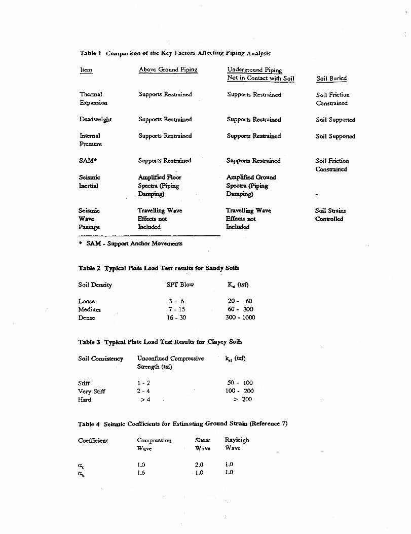
Table 1 Comparison of the Key Factors Affecting i'iping Analysis
Item Above Ground Piping Underground Piping Not in Contact with Soil Soil Buried
Thermal Expansioa
Supports Restrained Supports Restrained Soil Friction Constrained
Deadweight Supports Restrained Supports Restrained Soil Supported
Internal Pressure
Supports Restrained Supports Restrained Soil Supported
SAM*
Seismic Ineitial
Supports Restrained
Amplified Floor Spectra (Piping Damping)
Supports Restrained
Amplified Ground Spectra (Piping Damping)
Soil Friction Constrained
Seismic Wave Passage
Travelling Wave Effects not Included
Travelling Wave Effects not Included
Soil Strains Controlled
* SAM - Support Anchor Movements
Table 2 Typical Plate Load Test results for Sandy Soils
Soil Density SPT Blow Kj (tsf)
Loose Medium Dense
3 - 6 2 0 - 60 7 - 15 6 0 - 300 1 6 - 3 0 3 0 0 - 1000
Table 3 Typical Plate Load Test Results for Clayey Soils
k,,(tef) Soil Consistency Unconfined Compressive Strength (tsf)
Stiff Very Stiff Hard
1 - 2 2 - 4
> 4
5 0 - 100 1 0 0 - 200
> 200
Table 4 Seismic Coefficients for Estimating Ground Strain (Reference 7)
Coefficient Compression Wave
Shear Rayleigh Wave Wave
1.0 1.6
2.0 1.0 1.0 1.0

Table 5 Effective Friction Angle (<fia) in Degrees Soil Type
Sand & Gravel Mixtures fm Sands, S i l t y cm Sands f Sands , S i l t y fm Sands N o n p l a s t i c S i l t s , Sandy S i l t s Very S t i f f Clays m S t i f f To S t i f f Clays
Concrete Pipe S t e e l Pipe i n s t S o i l Formed New Rusted
29 - 31 22 - 26 22 29 24 - 29 17 - 22 17 24 19 - 24 17 14 20 17 - 19 14 1 1 16 22 - 26 18 15 15 17 - 19 13 1 0 15
f = f i n e , m = medium, c = coarse g r a i n s i z e d e s c r i p t o r
Table 6 Effect ive Adhesion (C4) for Cohesive S o i l s ( in 287)
S o i l Consis tency Cohesive S t reng th C E f f e c t i v e Adhesion C t
Very Sof t Sof t Medium S t i f f S t i f f Very S t i f f
0 - 250 250 - 500 500 - 1000
1000 - 2000 2000 - 4000
0 - 250 250 - 500 500 - 750 750 - 950 950 - 1300
Table 7 Design Parameters Used fo r t h e Example
INNER PIPE OUTER PIPE Material A312-304L stainless steel A106-GRB Carbon Steel Size 3"Sch.40 6" Sen. 40 Diameter 3.500" 6-625" Thickness 0.216" 0.280" Linear Weight 10.96 lb/ft with fluid 19.46 lb/ft empty Internal Pressure 200 psi Atmospheric Op. Temperature 180^ Atmospheric Const. Code ASMEB31.3 ASMEB31.3 Sy Ambient 25,000 psi 35,000 psi S Ambient 15,700 psi 15,000 psi E 28.3E6 psi 29.5 E6 psi a 9.3E-6 in/in 0 F 6.3E-6 in/ in 0 F

T a b l e 8 Maximum S t r e s s e s f o r I n d i v i d u a l Load Case
Load Case Maximum S t r e s s ( k s i ) I nne r P i p e Ou te r P ipe
P r e s s u r e 0.8 1.2 Deadweigh t 2 .4 3 . 0 The rma l Expansion 12 .8 0 .4 N a t u r a l S o i l S e t t l e m e n t 0 0 Wave P a s s a g e . 1.7 7 . 7 I n e r t i a 5.3 0 .8 O s c i l l a t o r y 5 .0 14 .4 S e t t l e m e n t SAM 3.9 6 .7
Table 9 Comparison o f t h e combined s t r e s s e s and the A l l o w a b l e s
PD/4t + .75i(M D W + Mi)/Z £ min (2S, 2Sy) (7.13)
0.8 + 2.4 + 5.3 = 8.5 < min (3 x 15.7, 2 x 25.0) inner pipe
1.2 + 3.0 + 0.0 = 4.2 < min (3 x 15.0, 2 x 35.0) Outer pipe
et = Ks ae/E < 2% (SS), 1% (CS) (7.14)
6.6X8.5/28.3E3 = 0.2% <2% inner pipe
5.0 X 4.2 / 29.5E 3 = 0.07% < 1% outer pipe
f(Fw + F 0 )+ FrJ/A + i [(MW + Mo) + MTJ/Z < min (3S, 2Sy) (7.1S) (7.16a)
0.0 + 0.0 + 0.0 + 1.7 + 5.0 + 12.8 = 19.5 < min (3x15.7, 2x25.0) inner pipe
0.5 + 0.0 + 0.0 + 7.7 + 14.4 + 0.4 = 23.0 < min (3 x 15.0, 2 x 35.0) outer pipe
(Fs + FT) /A + i (Ms + MT) /Z < min (3S, 2Sy) (7.15) (7.16b)
0.0 + 0.0 + 3.9 + 12.8 = 16.7 < min (3 x 15.7, 2 x 25.0) inner pipe
0.0 + 0.0 + 6.7 + 14.4 = 21.1 < min (3 x 15.0, 2 x 35.0) outer pipe
e t = Ks <JS/E < 4%, 2% (branch, tee) (7.14)
6.66 x 3.9 / 28.3E3 = 0.09% < 4% inner pipe
5.0 x 6.7 / 29.5E3 = 0.1% < 4% outer pipe