seismic design of braced frame gusset plate connections · pdf filethis leads to the very...
TRANSCRIPT

Seismic design of braced frame gusset plate connections C. W. Roeder, D. E. Lehman, A. Christopolus, I. Gunnarson, S. Johnson & J. H. Yoo Department of Civil and Environmental Engineering, USA
Abstract
Steel concentrically braced frames (CBFs) are stiff and strong and are an economical method to control damage during small, frequent seismic events. During severe, infrequent earthquakes, CBFs develop inelastic deformation through axial tensile yielding and post-buckling deformation of the brace. The inelastic deformation demands of the brace places severe force and deformation demands on the gusset plate connections. As such, the frame response depends on the connection response as well. To better understand the frame response of CBF systems, an analytical and experimental research study into the seismic performance of CBFs with an emphasis on better understanding the response and design of gusset plate connections is underway. The research examines the yield mechanisms and failure modes encountered in the design of gusset plate connections. To achieve a more balanced design which better distributes yielding throughout the system, a design procedure that provides economical design and good seismic performance by balancing the yield mechanisms and failure modes is proposed. Experimental research to evaluate the proposed procedures is underway. This experimental program is described, and initial test results are summarised. Complementary theoretical studies are used to establish mathematical models to estimate the connection properties and to perform parametric studies to better understand the influence of the connection on the frame response. Keywords: braced frames, buckling, connections, gusset plate connections, seismic design.
1 Introduction
Concentrically braced frames (CBFs) are commonly used for seismic design, because their strength and stiffness economically satisfies serviceability design
© 2005 WIT Press WIT Transactions on The Built Environment, Vol 81, www.witpress.com, ISSN 1743-3509 (on-line)
Earthquake Resistant Engineering Structures V 105
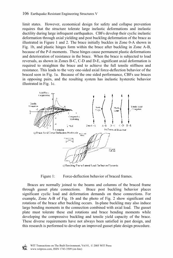
limit states. However, economical design for safety and collapse prevention requires that the structure tolerate large inelastic deformations and inelastic ductility during large infrequent earthquakes. CBFs develop their cyclic inelastic deformation through axial yielding and post buckling deformation of the brace as illustrated in Figure 1 and 2. The brace initially buckles in Zone 0-A shown in Fig. 1b, and plastic hinges form within the brace after buckling in Zone A-B, because of the P-δ moments. These hinges cause permanent plastic deformations and deterioration of resistance in the brace. When the brace is subjected to load reversals, as shown in Zones B-C, C-D and D-E, significant axial deformation is required to straighten the brace and to achieve the full tensile stiffness and resistance. This leads to the very one-sided axial force-deflection behavior of the braced seen in Fig. 1a. Because of the one sided performance, CBFs use braces in opposing pairs, and the resulting system has inelastic hysteretic behavior illustrated in Fig. 1c.
Figure 1: Force-deflection behavior of braced frames.
Braces are normally joined to the beams and columns of the braced frame through gusset plate connections. Brace post buckling behavior places significant cyclic load and deformation demands on these connections. For example, Zone A-B of Fig. 1b and the photo of Fig. 2 show significant end rotations of the brace after buckling occurs. In-plane buckling may also induce large bending moments in the connection combined with axial load. The gusset plate must tolerate these end rotations and brace bending moments while developing the compressive buckling and tensile yield capacity of the brace. These diverse requirements have not always been satisfied in past design, and this research is performed to develop an improved gusset plate design procedure.
© 2005 WIT Press WIT Transactions on The Built Environment, Vol 81, www.witpress.com, ISSN 1743-3509 (on-line)
106 Earthquake Resistant Engineering Structures V

Figure 2: Photo of buckled brace.
Figure 3: Gusset plate connection.
2 Proposed design procedure
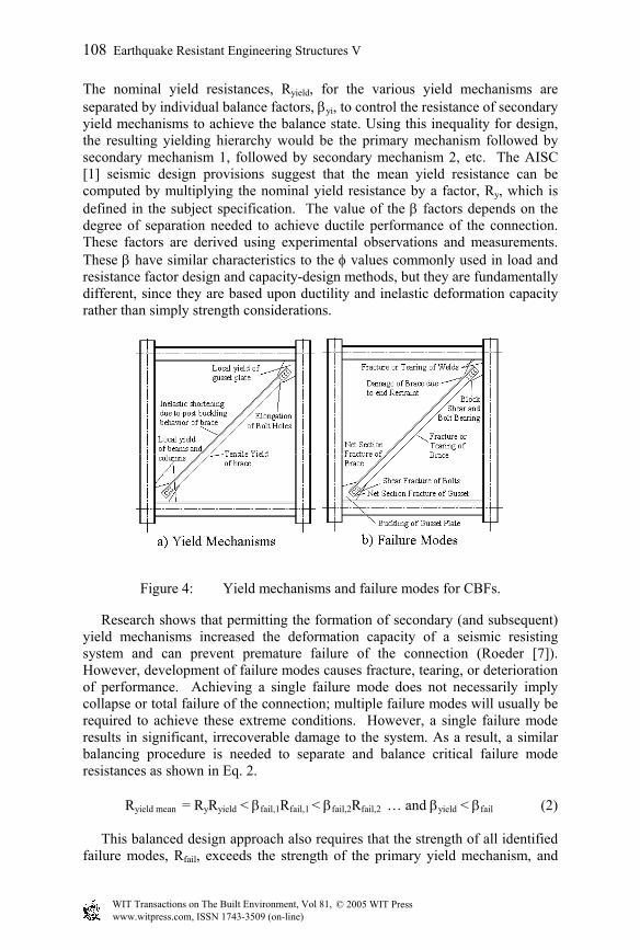
To meet these diverse objectives, a seismic design methodology based on balancing the yield mechanisms and preventing undesirable failure modes is proposed. In traditional seismic design, plastic design principles are used and the elements are designed to meet the elastic force demands. The specific elements that are expected to yield (e.g., braces in CBFs) are designed to sustain the cyclic inelastic deformation demands. Capacity design principles are used to design the adjacent elements. The proposed balanced design approach is similar to traditional seismic design methods in that the framing elements are designed to meet the elastic force demands and the brace is designed to have tensile yield and post-buckling inelastic deformation and to achieve the desired plastic mechanism of the system. This process is likely to satisfy serviceability design limits automatically, since all members will have yield resistance greater than a specified seismic resistance. Collapse prevention and life safety design objectives require significant ductility of the structural system, and a sequence of yielding is desirable. This sequence of yielding assures that significant inelastic deformation can occur before undesirable failure modes are permitted. It further requires a sequencing of the failure modes to provide optimal ductility and inelastic deformation capacity. Further, proportional separation is provided between desirable and less desirable behaviors to reduce the probability of less acceptable yield mechanisms and failure modes occurring prematurely. Figure 4 illustrates the possible yield mechanisms and failure modes for CBFs, and Eq. 1 expresses the proposed balance procedure as:
Ryield mean = RyRyield < βy1RyRyield,1 < β y 2RyRyield,2 ... < β y iRyRyield,i (1)
© 2005 WIT Press WIT Transactions on The Built Environment, Vol 81, www.witpress.com, ISSN 1743-3509 (on-line)
Earthquake Resistant Engineering Structures V 107
The nominal yield resistances, Ryield, for the various yield mechanisms are separated by individual balance factors, βyi, to control the resistance of secondary yield mechanisms to achieve the balance state. Using this inequality for design, the resulting yielding hierarchy would be the primary mechanism followed by secondary mechanism 1, followed by secondary mechanism 2, etc. The AISC [1] seismic design provisions suggest that the mean yield resistance can be computed by multiplying the nominal yield resistance by a factor, Ry, which is defined in the subject specification. The value of the β factors depends on the degree of separation needed to achieve ductile performance of the connection. These factors are derived using experimental observations and measurements. These β have similar characteristics to the φ values commonly used in load and resistance factor design and capacity-design methods, but they are fundamentally different, since they are based upon ductility and inelastic deformation capacity rather than simply strength considerations.
Figure 4: Yield mechanisms and failure modes for CBFs.
Research shows that permitting the formation of secondary (and subsequent) yield mechanisms increased the deformation capacity of a seismic resisting system and can prevent premature failure of the connection (Roeder [7]). However, development of failure modes causes fracture, tearing, or deterioration of performance. Achieving a single failure mode does not necessarily imply collapse or total failure of the connection; multiple failure modes will usually be required to achieve these extreme conditions. However, a single failure mode results in significant, irrecoverable damage to the system. As a result, a similar balancing procedure is needed to separate and balance critical failure mode resistances as shown in Eq. 2.
Ryield mean = RyRyield < βfail,1Rfail,1 < βfail,2Rfail,2 … and βyield < βfail (2) This balanced design approach also requires that the strength of all identified failure modes, Rfail, exceeds the strength of the primary yield mechanism, and
© 2005 WIT Press WIT Transactions on The Built Environment, Vol 81, www.witpress.com, ISSN 1743-3509 (on-line)
108 Earthquake Resistant Engineering Structures V

that less favorable failure modes have greater separation than more favorable failure behaviors. In some cases, prescriptive details such as slenderness limits or weld type may be provided to limit the need to check one or more individual failure mode (FEMA 350 [6]). Each yield or failure balance parameter, βyield or βfail, is calculated as the ratio of the mean or expected value of the experimentally observed behavior, and the value is increased or decreased based upon the desirability of the outcome for that particular behavior combination. An earlier paper (Roeder et al. [8]) has discussed β values that are proposed for CBF and MRF systems. The latter were based on research performed as part of the SAC Steel Project.
3 Experimental Investigations
This balance procedure requires a comprehensive theoretical and behaviorial understanding of CBF systems, including understanding of the behaviours of the individual braces and gusset plate connections. As a result, experimental investigations are in progress to examine CBF frame behavior and the consequence of this behavior on gusset plate connection design. The experiments are performed on braced frame subassemblages. The specimens, shown in Figure 5, which are tested in a horizontal position, simulate a full scale single braced bay typical of that required for a 3- or 4- story building and include a single brace, two beams and two columns.
Figure 5: Schematic of test setup.
The frames are subjected to a monotonically increasing cyclic inelastic deformation history, which was based on the ATC-24 testing protocol. This test
© 2005 WIT Press WIT Transactions on The Built Environment, Vol 81, www.witpress.com, ISSN 1743-3509 (on-line)
Earthquake Resistant Engineering Structures V 109
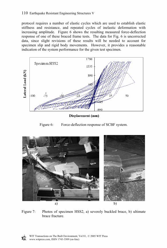
protocol requires a number of elastic cycles which are used to establish elastic stiffness and resistance, and repeated cycles of inelastic deformation with increasing amplitude. Figure 6 shows the resulting measured force-deflection response of one of these braced frame tests. The data for Fig. 6 is uncorrected data, since slight revisions of these results will be needed to account for specimen slip and rigid body movements. However, it provides a reasonable indication of the system performance for the given test specimen.
Figure 6: Force-deflection response of SCBF system.
a) b)
Figure 7: Photos of specimen HSS2, a) severely buckled brace, b) ultimate brace fracture.
© 2005 WIT Press WIT Transactions on The Built Environment, Vol 81, www.witpress.com, ISSN 1743-3509 (on-line)
110 Earthquake Resistant Engineering Structures V
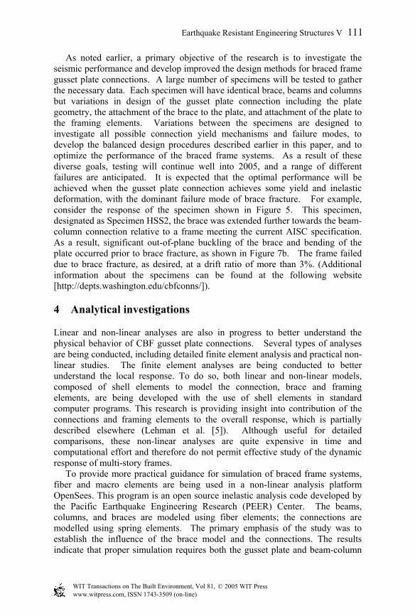
As noted earlier, a primary objective of the research is to investigate the seismic performance and develop improved the design methods for braced frame gusset plate connections. A large number of specimens will be tested to gather the necessary data. Each specimen will have identical brace, beams and columns but variations in design of the gusset plate connection including the plate geometry, the attachment of the brace to the plate, and attachment of the plate to the framing elements. Variations between the specimens are designed to investigate all possible connection yield mechanisms and failure modes, to develop the balanced design procedures described earlier in this paper, and to optimize the performance of the braced frame systems. As a result of these diverse goals, testing will continue well into 2005, and a range of different failures are anticipated. It is expected that the optimal performance will be achieved when the gusset plate connection achieves some yield and inelastic deformation, with the dominant failure mode of brace fracture. For example, consider the response of the specimen shown in Figure 5. This specimen, designated as Specimen HSS2, the brace was extended further towards the beam-column connection relative to a frame meeting the current AISC specification. As a result, significant out-of-plane buckling of the brace and bending of the plate occurred prior to brace fracture, as shown in Figure 7b. The frame failed due to brace fracture, as desired, at a drift ratio of more than 3%. (Additional information about the specimens can be found at the following website [http://depts.washington.edu/cbfconns/]).
4 Analytical investigations
Linear and non-linear analyses are also in progress to better understand the physical behavior of CBF gusset plate connections. Several types of analyses are being conducted, including detailed finite element analysis and practical non-linear studies. The finite element analyses are being conducted to better understand the local response. To do so, both linear and non-linear models, composed of shell elements to model the connection, brace and framing elements, are being developed with the use of shell elements in standard computer programs. This research is providing insight into contribution of the connections and framing elements to the overall response, which is partially described elsewhere (Lehman et al. [5]). Although useful for detailed comparisons, these non-linear analyses are quite expensive in time and computational effort and therefore do not permit effective study of the dynamic response of multi-story frames. To provide more practical guidance for simulation of braced frame systems, fiber and macro elements are being used in a non-linear analysis platform OpenSees. This program is an open source inelastic analysis code developed by the Pacific Earthquake Engineering Research (PEER) Center. The beams, columns, and braces are modeled using fiber elements; the connections are modelled using spring elements. The primary emphasis of the study was to establish the influence of the brace model and the connections. The results indicate that proper simulation requires both the gusset plate and beam-column
© 2005 WIT Press WIT Transactions on The Built Environment, Vol 81, www.witpress.com, ISSN 1743-3509 (on-line)
Earthquake Resistant Engineering Structures V 111

connections must be modeled. Figure 8 shows a comparison of the measured lateral force to lateral displacement behavior to one of the braced frame specimens. Figure 8a is a schematic of the member sizes and loading of this test specimen. The comparison between analysis and experimental results are quite good as can be seen in Fig. 8b, but the post yield resistance is less well estimated. The analysis has shown that this post yield resistance is strongly influenced by connection stiffness and yield deformation. The results indicate that the ability to accurately model connection performance using this analysis tool is limited. Nevertheless, relatively good correlation has been obtained in comparing theoretical predictions to experimental results. Further work is proceeding in defining the connection stiffness, resistance and inelastic performance. The results will be used to develop practical analytical models for the seismic simulation of braced frame systems.
Figure 8: (a) Test frame and (b) analytical and experimental results.
5 Closing comments
This research program is ongoing and improvements in the seismic design and analysis procedures for braced frames and their connections are expected. This research work is funded by the National Science Foundation through Grant CMS-0301792, Performance-Based Seismic Design of Concentrically Braced Frames. Dr. Steven L. McCabe is the Program Manager for this research. This financial support is gratefully acknowledged.
References
[1] AISC (2002) "Seismic Provisions for Structural Steel Buildings," American Institute of Steel Construction, Chicago, IL.
[2] FEMA 355D (2000). “State of Art Report – Connection Performance”, FEMA 355D, Federal Emergency Management Agency, Washington, D.C.
© 2005 WIT Press WIT Transactions on The Built Environment, Vol 81, www.witpress.com, ISSN 1743-3509 (on-line)
112 Earthquake Resistant Engineering Structures V

[3] FEMA 355F (2000). “State of Art Report on Performance Prediction and Evaluation of Steel Moment-Frame Buildings”,
[4] FEMA 355F, Federal Emergency Management Agency, Washington, D.C.
[5] FEMA 350 (2000) "Recommended Seismic Design Criteria for New Steel Moment-Frame Buildings," Federal Emergency Management Agency, Washington, D.C., July 2000.
[6] Lehman D., Roeder, C., Yoo, J.H., and Johnson, S. Seismic Response of Braced Frame Connections, 13th WCEE, Vancouver, B.C., Canada, August 2004.
[7] Roeder, C.W., (2002) "Connection Performance for Seismic Design of Steel Moment Frames," ASCE, Journal of Structural Engineering, Vol 128, No. 4, pgs 517-25.
[8] Roeder, C.W., Lehman, D.E., and Yoo, J.H., (2005). "Improved Seismic Design of Steel Frame Connections,” KSSC, International Journal of Steel Structures.
© 2005 WIT Press WIT Transactions on The Built Environment, Vol 81, www.witpress.com, ISSN 1743-3509 (on-line)
Earthquake Resistant Engineering Structures V 113