seismic hazard maps and building codes -an … · seismic hazard maps and building codes -an...
TRANSCRIPT
SEISMIC HAZARD MAPS AND BUILDING CODES -AN INTRAPLATE REGION EXPERIENCE
DR. JAMES E. BEAVERS MID-AMERICA EARTHQUAKE CENTRE
INVITED SPEAKER
James E. Beavers, Ph.D., P.E. is the Deputy Director of the Mid-America Earthquake Center at the University of Illinois, Urbana, Illinois, USA
(Full paper not available at time of printing)
This paper will address the issues of integrating seismic hazard maps into building codes for
the central and eastern United States (CEUS), an area of infrequent but high consequence
earthquakes. The paper will discuss the history of seismic mapping and code adoption going
back to the first United States (US) seismic code, the 1927 Uniform Building Code. The
paper will discuss the evolution of seismic hazard maps, seismic design guidelines and codes
in the US and their application in the CEUS. The paper will highlight "Project 97 -- NEHRP
Seismic Hazard Mapping and Seismic Risk Design Values" that was created in 1994 and led to the use of a new evolution of seismic hazard maps and seismic design concepts in the US.
The paper will close by talking about the new 2000 International Building and Residential
Codes and the trials and tribulations about their adoption in communities in the CEUS.
Paper No.1
SEISMIC RISK IN PACIFIC CITIES: IMPLICATIONS FOR PLANNING, BUILDING CODE LEGISLATION AND URBAN SEARCH AND RESCUE
SERVICES
DR. GRAHAM B. SHORTEN SOPAC,SUVA
INVITED SPEAKER
(Full paper not available at time of printing)
(This presentation will reflect the outcomes of the SOPAC-UNOCHA regional workshop 'Building Safer Urban Communities in the South Pacific', Suva, 7-9
11' November, 2001)
Paper No.2

Australian Earthquake Engineering Society Conference, 'Earthquake Codes in the Real World', Canberra, 21-23'd November, 2001
ABSTRACT
Seismic Risk in Pacific Cities: Implications for Planning, Building Code Legislation, and Urban Search and Rescue Services
Dr Graham G. Shorten
SOPAC, Suva
Many of the urban areas of the Pacific Basin face what is probably the highest risk of any in the world. The risk arises from a combination of some of the highest levels of seismic hazard along the Ring of Fire, and the vulnerability of the building stock and populace due to poor planning, unlegislated building standards, often poor foundation conditions and a low level of preparedness.
The fragile economies of the Pacific Island Countries are based largely on the security of these cities, and hence the risk to the sustainable development of the nations themselves is high, and their future uncertain. The ripple effects following the shock of the terrorist attack on New York's World Trade Center demonstrate only too clearly the national economic impact arising from the destruction of even a small part of a city's commercial heart.
A number of organisations dealing with disaster mitigation in the region are now focussed on jointly developing an awareness of risk in the Pacific nations, appropriate planning for development, legislation and enforcement of relevant building codes, and an immediate, local capacity for urban search and rescue in the face of disaster.
Efforts are being concentrated on developing and supporting national disaster management offices at a high level in the various Governments, to link and coordinate urban planning, public works, fire and emergency response organisations and police and military services. National development is very much seen as being predicated on successful management of risk, and most notably risk due to seismic hazard.
A joint project between the Geophysical Institute of Israel, IRD France and SOPAC has seen seismic hazard defined for five of the largest Pacific cities, and a microzonation of the hazard based on foundation conditions. The work has shown that unexpectedly high accelerations are possible and that foundation conditions in many areas are extremely poor.
Concurrently, geographic information system databases have been developed for the cities which include descriptions of the building stock, lifelines and populations at risk. Work is proceeding to evaluate the risk to those vulnerable elements from a range of hazards including seismic hazards.
National institutions of engineers and architects have hitherto adopted ad hoc standards borrowed from other countries or developed through aid projects, and are now pushing for the formal adoption, legislation and enforcement of standard national building codes.
The experience of Kobe, Turkey and New York in recent times has underlined the need for rapid and effective response after disasters and the need to have systems of local response developed that can operate without being hamstrung by the juggernaut of bureaucratic procedures and dependence on vulnerable transport and communication systems. Models for successful urban search and rescue in Pacific cities are currently being fashioned.
The traditional societies of the Pacific generally demonstrate a high level of risk-acceptance balanced out by strong community-support mechanisms and high intrinsic resilience, and yet the modern cities on which national survival may teeter are some of the most vulnerable in the world. Finding the appropriate response systems and effecting change to build safer urban communities is not only a problem of a lack of finance but one of education, awareness and acceptance. An agreed framework for future preventative and protective action by relevant national authorities is emerging .
(This presentation will reflect the outcomes of the SOPAC-UNOCHA regional workshop 'Building Safer Urban Communities in the South Pacific', Suva, 7-9tn November, 2001)
Page 2-1

THE JOINT AUSTRALIAN EARTHQUAKE LOADING STANDARD:
AUTHORS:
CHALLENGES AND DIRECTIONS
JOHN WILSON AND NELSON LAM THE UNJVERSITY OF MELBOURNE
John Wilson is Senior Lecturer at the University of Melbourne. He was with Ove Arup and Partners before becoming Senior Lecturer at The University of Melbourne in 1992. He is co-author of a book and numerous publications in many different areas of earthquake engineering and structural dynamics.
Nelson Lam is Senior Lecturer at The University of Melbourne. He joined Scott Wilson Kirkpatrick & Partners in 1982 and was bridge engineer with the firm until 1989 when he began his academic career at The University of Melbourne specialising in the field of earthquake engineering.
ABSTRACT:
A committee (BD/6/4) was formed in 1996 to develop a Joint Australian/New Zealand Earthquake Loading Standard with New Zealand facilitating the process. The task of drafting a joint earthquake loading standard has been challenging due to the different levels of seismicity and the significantly different design approaches currently adopted by the two countries. A number of issues have been highlighted including the formatting of standard for building code citation, the interface between the loacling standard and the material standards, the selection of the appropriate return periods for different facilities and the associated seismic design forces, the seismic design methodologies and verification procedures. The current draft appears very similar to the existing New Zealand Seismic Standard in both format and approach. Four verification procedures (VP) have been proposed in the draft ANZ, with VP"O" and VP"I" generally appropriate for Australia and VP"II" and VP"ill ' appropriate for New Zealand. The industry experience in the application of AS 1170.4 has been that engineers generally try to find "escape clauses" so that earthquake de ign loading and the associated design considerations can be minimisecl or avoided. A preferred situation would be for all structures to be checked for the appropriate earthquake loading and checked to ensure that viable load exist in the structure from roof level to the foundation. Further, the structure should have some deformation capacity and "toughness" so that brittle modes of failure are discouraged. The VP"O" and VP"I" procedures specified in the draft ANZ do little to improve this situation. Clearly, this is a priority issue to be addressed in the development of the Joint Standard.
Paper No.3
1. INTRODUCTION
Australia and Ne'' Zealand agreed in 1992 to produce joint standards. and where possible to align with international standards (ISO). In addition, there is an initiative to produce unified fmmats for loading standards consistent with ISO within the APEC countries. In the earthquake loading context, this implies future consistency with IS030 10.
A committee (BD/6/4) was fanned in 1996 to develop a Joint Australian/ New Zealand Earthquake Loading Standard with New Zealand facilitating the process. A series of working groups were established to develop a state-of-the-art review in a number of topical areas including: seismic hazard modelling, design methodologies. analysis techniques and non-strucn1ral components. Included in this process was a review of other leading international earthquake standards such as the Eurocode 8, Uniform Building Code (USA), the Japanese Seismic Standard and IS03010. The outcome of the working groups formed the basis of the brief for the preparation of the draft standard. The draft was produced by the New Zealand consultants Beca Carter Hollings and Ferner under contract dming the period !999-2000. Following an intemal review involving the working group parties, the draft 'Part 4 : Earthquake Actions' Standard and Commentary (DR00902, DR00903) were issued for public comment in November. 2000, together with the draft 'Part 0: General Requirements' Standard (DR00904) prepared by a separate group. The public comment submissions closed in May 2001 with an overwhelming response and the comments are currently under consideration by the drafting standards committee and the contractor.
The task of drafting a joint earthquake loading standard was known to be challenging. For example, the seismic activities and engineering practices of the two countries are very different. ln New Zealand, the seismic hazard level ranges from moderate (Auckland) to high (Wellington), whereas in Australia the seismicity ranges from low to moderate. A viable approach for the development of the joint standard is to adopt a two-tier strategy: one tier for the low-moderate seismic regions and the other tier for the higher seismic regions. This implies that the seismic design approach for Auckland would be similar to some regions in Australia. This clearly poses a challenge since the existing seismic design approaches in the two countries are fundamentally different.
The aim of this paper is to review and discuss contentious issues associated with the draft Joint Australian/New Zealand Earthquake Loading Standard (ANZ) and to compare this draft doctm1ent with the existing Australian Earthquake Loading Standard (AS 1170.4:1993 ). In general, the draft ANZ appears to be strongly influenced by the existing New Zealand Earthquake Design Standard, and the format appears more complex than AS 1170.4 and the notation is not consistent with IS030 10. One other notable difference between the Standards is that the parts refening to "Domestic Structures" and load-bearing masomy buildings in AS 1170.4 is not included in the Draft ANZ.
2. FORMATTING OF STANDARDS FOR BUILDING CODE CITATION
Design Standards can be described as the "contact point" between the art and science of engineering and the regulatory ti·amework. The regulato1y ti·amework consists of regulations established through acts of parliament. In the context of building construction, these regulations are embodied in design documents such as the Building Code of Australia (BCA).
The BCA calls up standards which are relevant to the design issues being considered, such as the loading and material standards. The Australian Building Control Board (ABCB) has the responsibility to ensure that all designs comply with the BCA, which is usually achieved through a certification process involving bodies such as local govemments, registered engineers and registered building surveyors. The ABCB prefers standards to provide "verification methods" or "deemed to satisfy solutions" and discourages clauses which rely on engineering judgement or discretion leading to an open-ended solution. Consequently, the draft standard contains mostly definitive statements as to what
Page 3-1

needs to be done and the criteria to be satisfied. without involving open-ended professional engineering judgement (as is often associated with performance-based design standards).
The committee reviewing the draft standard has been most uncomfortable with the fact that engineering judgement and "best practice" has been virnmlly excluded from the standard. It is difficult to codify a huge body of knowledge (i .e. text books. technical papers, computer programs. design aids) and a very complex design and analysis process into a definitive verification procedure. This has also resulted in new state-of-the-art design methodologies such as the "Displacement Based" methods being excluded from the current draft. Ironically, most buildings are founded on soils where engineering judgement on geotechnical issues is absolutely essential for the successful design of the foundation. Following discussions with the ABCB and the New Zealand Building Industry Association (BIA), it is understood that some engineering judgement will be considered for inclusion in the next revision of the draft Earthquake Loading Standard.
3. INTERFACE OF LOADING STANDARDS WITH MATERIAL STANDARDS
The current earthquake loading standard (AS 1170.4) addresses earthquake loading, detailing and design aspects. A decision was made very early in the drafting of the ANZ to separate earthquake loading from earthquake design. Earthquake design will fom1 part of the materials standards whilst earthquake loading will be the subject of ANZ. The interface between the material and loading standards is the ductility factor. Ideally, the loading standard should specify the ductility factors for different strucnu·al systems. whilst the material standards should specify the detailing and design requirements consistent with these ductility values . However. in the cun-ent draft ANZ, the ductility factors have not been specified but instead the user is referred to the appropriate material standards. It is recommended that at least minimum ductility values be specified in the loading standard so that a definitive earthquake load can be obtained without reference to the material standard. Considerable further work is required to re-draft the material standards in both Australia and New Zealand to ensure compatibility and consistency before the earthquake loading standard can be released.
4. LlMIT STATE EARTHQUAKE FORCES AND RETURN PERIODS
The methodology in the draft ANZ for the calculation of the base shear force is similar in fom1at to the existing New Zealand earthquake standard and generally consistent with AS 1170.4, and is shown in Fig.!. Some of the significant differences associated with the base shear force calculation are highlighted in this section.
A new normalised response spectrum for Australia has been included in the draft ANZ, and is significantly lower than the current AS 1170.4 spectrum. A detailed review and discussion on this issue is provided in the companion paper (Lam, 200 I). Soil amplification effects have been accounted for using the method proposed by Crouse ( 1996) and do not explicitly account for soil resonance effects for very soft and deep soil sites.
I '= C IV "
(I)
11•here IV is the 11•eight nf the building am/ C,, is the lateral design action coefficient tlefined
as follow~· :
c = c,(T,)ZR,s,. "
(2) p
C1, (T, )ZR, i.~ effecti vely the elastic re.1pouse spectrum am/ C1, (T,) is the nomwlised resp ouse .1pectru111 ,
Z is till accelemtinn cnefficieut repre.~enting the seismicity , and R, is a refilm period factor tn udjust the loads
for retum p eriods which differ fro m the stnndurd 500 rear r<'flll'll p eriod eJ•ent. Th e ratio.!!___ is tl1e equivalent to the . . ~
stmctura/ respon .~e factor in AS/ 170.4 11•1lere p is the ductilt~t' fit ctor (refer Section 3) and Ys can be inte1preted as the ' I'
o l'erslrell.f.:tll j(rctnr (and is in the order nf /. 5) .
Figure I Earthquake Base Shear Force alculation
Page 3-2
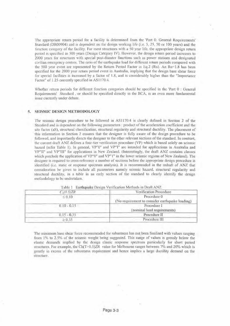
The appropriate return period for a facility is detem1ined ti·om the 'Pat1 0: General Requirements' Standard (DR00904) and is dependent on the design working life (i.e. 5, 25, 50 or 100 years) and the function category of the facility. For most stmch!res with a 50 year life. the appropriate design retum period is specified as 500 years (Design Category IV). However, the des1gn rehml period increases to 2000 years for structures with special post-disaster functions such as power stations and designated civilian emergency centres. The ratio of the earthquake load for different retum periods compared with the 500 year event are represented by the Reh1rn Period Factor in Eq.2 (Ru). An Ru= l.8 has been specified for the 2000 year return period event in Australia, implying that the design base shear force for special facilities is increased by a factor of 1.8, and is considerably higher than the "Importance Factor" of 1.25 currently specified in AS 1170.4.
Whether reh1rn periods for different function categories should be specified in the 'Part 0 : General Requirements' Standard , or should be specified directly in the BCA, is an even more fundamental issue currently under debate.
5. SEISMIC DESIGN METHODOLOGY
The seismic design procedure to be followed in AS 1170.4 is clearly defined in Section 2 of the Standard and is dependent on the following parameters : product of the acceleration coefficient and the site factor (aS), structural classification, stmctural regularity and structural ductility. TI1e placement of this information in Section 2 ensures that the designer is fully aware of the design procedure to be followed, and importantly directs the designer to the other relevant sections of the standard. In contrast, the current draft ANZ defines a four-tier verification procedure (VP) which is based solely on seismic hazard (refer Table 1 ). In general, VP"O" and VP"I" are intended for applications in Australia and VP"fi" and VP"III" for applications in New Zealand. (Interestingly, the draft ANZ contains clauses which preclude the application of VP"O" and VP" I" in the lower seismic regions of New Zealand). The designer is required to cross-reference a number of sections before the appropriate design procedure is identified (i.e. static or response spectrum analysis) . It is recommended in the redraft of ANZ that consideration be given to include all parameters namely seismic hazard, structural regularity and struch1ral ductility, in a table in an early section of the standard to clearly identify the design methodology to be undertaken.
Table 1 Earthquake Design Verification Methods in Draft ANZ C~o(0.5)ZR Verification Procedure
~ 0.10 Procedure 0 (No requirement to consider earthquake loading)
0.10-0.15 Procedure I (nominal load requirements)
0.15-0.35 Procedure II :?: 0.35 Procedure III
The minimum base shear force reconunended for robush1ess has not been finalised with values ranging from I'% to 2.5"/t, of the seismic weight being suggested. This range of values is grossly below the elastic demands implied by the design elastic response spectrum particularly for short period struch1res. For example, the Ch(T=0.5)ZR value for Melboume ranges between 7% and 20% which is greatly in excess of the robustness requirement and hence implies a large ductility demand on the struch1re.
Page 3-3
It should be noted that the majority of structures in Australia \vill require a verification procedure of "0" or "!" (as defined in Table I). and hence will only be designed for a nominal base shear force. A preferred procedure would be for all structures to be checked for the base shear force as defined in Fig.!, and thus ensure that viable load paths exist throughout the structure from roof level to foundation. In addition, the designer should identify both the force and the displacement capacity of the struct11re associated with the likely failure mechanism when subject to excessive lateral load, and ensure that the ductility level assumed in the design is achieYable. For example, many low-rise structures in Australia are configured with a "soft-storey" in which case the actual ductility (or displacement) capacity can be very limited. This important consideration is addressed in Eurocode 8 by reducing the ductility factor for irregular structures, but is not specified in AS 1170.4 nor in the draft ANZ. These recommendations are considered of vital importance and justify the extra effort and understanding on the part of the Australian design engineer at the initial stage of the implementation.
Finally. the three-tier seismic design methodology reconunended for "pat1s and components" (nonstructural components) in the draft ANZ has addressed some of the shortcomings in the existing seismic codes for both Australia and New Zealand. However, the section requires some simplification to improve transparency and user-friendliness.
6. CLOSING REMARKS AND CONCLUSIONS
This paper has highlighted some of the significant issues concemed with the drafting of the ANZ standard. in particular:
• the formatting of standards for building code citation and the need for verification methods which discourage "best practice" and "engineering judgement" .
• the absence of explicit provisions for "Domestic" and load-bearing masonry structures.
• the interface between the loading standard and the material standards.
• the selection of tlu~ appropriate return periods for different facilities and the associated seismic design forces.
the seismic design methodologies and verification procedures.
The development of the Joint Seismic Loading Standard between Australia and New Zealand has been challenging due to the different levels of seismicity and the significantly different design approaches currently adopted by the two countries. The current draft appears very similar to the existing New Zealand Seismic Standard in both format and approach. Four verification procedures (VP) have been proposed in the draft ANZ, with VP"O" and VP"I" generally appropriate for Australia and YP"II" and VP"III" appropriate for New Zealand. The industry experience in the application of AS 1170.4 has been that engineers generally try to find "escape clauses" so that earthquake design loading and the associated design considerations can be minimized or avoided. A preferred sinmtion would be for all struct1Jres to be checked for the appropriate earthquake loading and checked to ensure that viable load exist in the structure from roof level to the foundation. Further, the sh11cture should have some deformation capacity and "toughness" so that brittle modes of failure are discouraged. The VP"O" and VP" 1" procedures specified in the draft ANZ do little to improve this situation. Clearly, this is a priority issue to be addressed in the development of the Joint Standard.
7. REFERENCES
AS 11 70.4 ( 1993) Standards Association of Australia : "Minimum design loads on structures : Part 4: Earthquake Loads - AS I 170.4 and Commentary ".
Page 3-4

Crouse C13. McGUire J w ( 1996). Stlc response studies for purpose or rcvismg NEH RP SCISmtc prOVISIOns . .lourualo(Earthquake .\;Jc:r·tm: 12(3): 407-419.
DR!\ FT 1\NZ (2000). l>mfl llu.wralum/N,•u· Zealcwd Stmulard jor Comuwur, Standards AustTaha and Standards :'-Jew Zealand Joint Document : DR00902-DR00904, tssucd 17th Novembcr,2000.
Ettr()Code 8 ( 1996) Ol!sign PrO\'isions /or Earthquake Resiswnce r~j'S11·ucrures. Brit ish Standards Institution. London.
ISO/ DIS 30 I 0 (lntcrnallOIWI Orgam/alton for Swndardtt:alton) lla.ws /ill' /)es(~n C)(Smwwre.r -Seismic Acl/011.1' 011 Struc/111'<'.\ .
Lam. N. r.K. and Wilson .. J.L (200 I). "Earthquake Response Spectnun Models for Australia''. Proceedings of the annual seminar for the 1\ust,·atian Earthquake Eng ineering Society, Canberra. This Volume.
Lntform 13utldtng C.:odc ( 199 I ). lntemat1onal Conference of Building Officials, Whtt ller. Califomia. USA.
Page 3-5
ISSUES RELATING TO A JOINT NZ/AUSTRALIAN EARTHQUAKE STANDARD
AUTHORS:
ANDREW KlNoCl) AND ROB JURy(2)
BUILDING RESEARCH ASSOCIATION OF NEW ZEALAND (BRANZ) (1)
BECA CARTER HOLLINGS AND FERNER LTD. (BECA), WELLINGTON(2)
Andrew King is the structural engineering manager at BRANZ and the chairman of the BD6/4 Earthquake Review standards subcommittee. He is also the New Zealand representative on ISO TC98 Actions on Structures. Mr King has worked in both the consulting and research engineering environment for over 30 years. He was chairman of the Loading Standards review committee which prepared the current New Zealand Loading Standard, NZS 4203.
Rob Jury is a Principal with Beca and directs the Wellington Structural Section of that firm. Mr Jury has widespread experience in both aseismic building design and in the development of earthquake hazard response assessments within New Zealand and elsewhere. Mr Jury headed the consultancy team commissioned by Standards New Zealand to prepare the public comment draft of the joint revision of the earthquake loading standard.
Paper No.4
ISSUES RELATING TO A JOINT NZ/AUSTRALIAN EARTHQUAKE STANDARD
A.B. King Building Research Association ofNew Zealand (BRANZ) R.D. Jury Beca Carter Hollings and Ferner Ltd. (Beca), Wellington.
ABSTRACT:
The development of a common earthquake standard was expected to be challenging since it is required to cover both the intraplate Australian and interplate New Zealand seismic environment. So it proved to be with the standards review committee now heavily embroiled in developing a standard which can be used within the two subtly different regulatory environments and by practitioners with significantly different operational procedures, all of whom have disparate expectations as to the importance of earthquake design for their buildings.
This paper outlines the essential features contained in the public comment draft. The strategy the review committee is following to address the many comments received is discussed along with the proposed means by which guidance is to be given to the related material standards committees so that they can develop the detailing and design requirements necessary to achieve the levels of structural deformation ductility assumed during the earthquake design. Other issues such as the linkages with other parts of the loading standard, the new robustness provisions of the General Design Requirements and the placement of societal value goals will also be discussed.
INTRODUCTION
The decision to revise and merge the New Zealand and Australian loading standards, NZS 4203, (SNZ 1992) and AS 1170 (SA 1989) was made in the mid 1990's as part of the governmental direction to align the two economies in accordance with the Closer Economic Relations (CER) agreement which has been in place since the mid-1980s. Industry consultation confirmed that common structural design standards were a desirable aspect of opening free trade, particularly of technical services between the two countries.
An initial meeting of patties affected by the proposed revision to the earthquake provisions was held in Melbourne in 1996 where it was agreed that the revision would include both technical amendments and alignment of the two standards. A series of expert working groups was formed and asked to highlight issues of significance. These were collated and formed the basis of a contract brief for drafting the joint standards revision. This draft was released for public comment in November 2000. Meanwhile the other parts of the Loading Standard revisions (eg General Design Requirements, Dead and Live Loads, and Wind Loads) had completed their public comment phase and were being revised in light of those comments.
The extent of the revision to Pat1 0: 'General Design Requirements' and the integral function it provides as an umbrella to Part 4 'Earthquake Loads' resulted in Part 0 being re-opened for limited public comment along with the earthquake provisions. Within New Zealand, their release generated considerable interest (and some disquiet) amongst many design professionals. The comments period was extended from February to April 2001 at the request of industry to enable commentators to develop considered comment. This culminated in over 150 pages of comments being submitted to Standards for consideration by the review committee.
THE JOINT LOADING STANDARD
The structure agreed for the joint loading standard was to split the standard into 5 discrete pat1s. Pm1 0: 'General Design Requirements' was expected to provide an umbrella over the specific loads defined in each of the other parts. As such it covers the general requirements such as building or occupancy classification and nomenclature and the load combinations to be used for
Page 4-1
both the serviceability and ultimate limit states. The loading intensity appropriate for buildings of differing importance was addressed by varying the recurrence interval over which the occurrence of the load was to be assessed ( eg temporary buildings are to have a short- 200 year - recurrence interval whereas buildings of national importance would need to consider loading events with recurrence intervals of up to 2500 years, with normal buildings required to consider loads with a I 0% probability of exceedence in 50 years- a recurrence interval of approximately 4 75 years). Specific loads and actions addressed included Part I: Permanent and Imposed loads (previously Dead and Live Loads), Part 2: Wind Loads, Part 3: Snow Loads, and Part 4: Earthquake Loads.
The drafting committee recognized that introducing change for change's sake was ill advised and attempted to retain as much ofthe current Australian Loading Standard, AS 1170, and the New Zealand equivalent, NZS4203, as practical but with the instruction from Standards New Zealand and Standards Australia to ensure that internationally recognized norms were to be applied wherever practical, specifically those accepted by the International Standards Organization, ISO. The primary areas of disparity between AS 1170 and NZS 4203 were the General Loading Requirements (previously absent from AS 1170) and the earthquake provisions.
The revised standard is to provide a basis for compliance with the structural requirements of the building regulations of both Australia and New Zealand as prescribed by the Building Code of Australia (BCA 1996) and the New Zealand Building Code (BIA 1992). At the time of drafting it was intended that the joint loading standard would be cited as a Deemed to SatisfY document within the BCA and as a Verification Method within the NZBC. This position has changed somewhat following the public comment review as discussed below.
Thus, while the Joint Loading Standard was required to satisfy subtly different building regulations, it was intended that the same technical content and presentational style was to be used in New Zealand and Australia. National variations are to be accommodated by reference to maps outlining the parameters appropriate for each country (ie wind speeds to be determined by reference to wind region maps; earthquake zones determined by reference to earihquake zonation maps). Some conditions would however only apply to one region (eg cyclonic winds, and earthquake spectra for very strong rock would only apply to Australia and Orographic winds to New Zealand).
EARTHQUAKE DESIGN OBJECTIVES
The formulation of the draft revision to Part 4: Earthquake Loads, was based on achieving three principle objectives. The objectives are that structures should be able to:
I. Resist frequent earthquake shaking (such as might reasonably be expected at least once in the design life of the structure) with a low probability of damage that would be sufficient to prevent the structure being used as originally intended without repair,
2. Withstand major earthquake shaking with a reasonable margin against collapse,
3. Withstand the most severe earthquake shaking that the structure is likely to be subjected to, with a small margin against collapse.
The first objective is simply a re-statement of the serviceability limit state. Objectives 2 and 3 represent two separate limit states but for the purposes of the proposed standard they are intended to be achieved by meeting one ultimate limit state. In moderate to severe seismic hazard areas it is expected that objective 3 will be met if objective 2 is met while in low seismic hazard areas it is expected that objective 3 will usually govern.
For New Zealand, verification of objective 2 is achieved using a loading level with the required level of risk. Compliance with objective 3 is achieved by defining a lower limit on the seismic hazard. The intention is to ensure that there is a reasonable chance that any structure will be
Page 4-2
able to survive earthquake shaking approaching the maximum credible event for the area without collapse. The maximum level of shaking that should be considered has been defined as either the maximum credible shaking for the site (with a 16% probability of exceedence) or that having a 2500 year return period whichever is the lesser. For the Auckland region for example the Maximum Credible Event (MCE) might be taken as the shaking resulting from a magnitude 6 earthquake with an epicentre say 20 km from the site.
GENERAL FRAMEWORK FOR EARTHQUAKE LOAD DETERMINATION
The draft standard deliberately separates the derivation of the seismic hazard from the derivation of the design earthquake actions. In this way the adjustments typically made to obtain design coefficients and spectra (eg adjustments at short periods ) are transparent. This aims to avoid the confusion that often arises when undertaking a site-specific earthquake hazard analysis as the results from such analyses are directly comparable with the hazard results provided in the standard and the same adjustments as defined in the standard can be made to obtain design values of earthquake load.
The proposed design process procedure is as follows;
1. Determine seismic hazard from Equation I C(T) = C11 (T)ZR (1)
Where Ch(T) is the normalized seismic hazard spectrum determined for the site soil category (A to E) Z is the hazard spectrum scaling factor determined from the site location by reference to the seismic zonation maps (one each for New Zealand & Australia) and, R is a function of the return period of the event appropriate for the occupancy classification
2. Determine the verification procedure required (ranging from I to Ill) for Building Code compliance. (Note the draft provided some instances where the robustness provisions of Part 0 were thought to be sufficient to provide an adequate level of earthquake resistance in low seismicity regions. This was strenuously questioned by commentators during the review and it is now likely that all primary structures (apa11 from domestic buildings) will be required to demonstrate they have a primary structure which can resist I% of the structural mass applied laterally at each floor with the connections being capable of resisting 5 times this action.)
3. Determine structural characteristics from the periods of vibration, seismic weight/mass, structural ductility factor J1, structural performance factor SP, structural regularity and structure functional category.
4. Determine design earthquake actions for the limit state under consideration from equations 2 and 3 with the design action applied at an accidental eccentricity of 0.1 times the plan dimension of the building at right angles to the direction ofloading.
cd = CI,(T)ZRsSp for the serviceability limit state (2)
cd = CI,(T)ZRllS/fl for the ultimate limit state (3)
For the equivalent static method the design actions are defined at T= T1•
5. Carry out the structural analysis using either the Equivalent Static Method or the Modal Response Spectrum Method. Restrictions are placed on the use of the Equivalent Static Method. The Numerical Integration Time History Analysis Method is expected to be reintroduced following industry commentators requests . Overall building deformation and interstorey drift limits for ultimate limit state conditions, together with guidance as to how elastic response configurations are to be scaled for inelastic behavior, are required.
Page 4-3
6. Verify that the requirements of the Building Code are met in accordance with the Verification Procedure required in 2 above. While Verification Procedure I is expected to simply result in buildings with a clearly defined lateral load path with the capacities of the connections being greater than those of the members in the primary structure, for Verification Procedures II and III, detailed design for lateral actions with a rational capacity design approach (eg weak-beam/strong-column) is required when buildings are designed for ductility levels greater than 3. In other cases concurrent ot1hogonal actions (70% plus 30% orthogonal) are required to be considered. There is an implicit expectation that the material standards used to verifY dependable structural capacities will include detailing provisions for various levels of structural ductility. Designers will be directed to assume elastic (!1 = 1.25) response unless ductile response can be justified through a material standard .
POST-COMMENTARY ISSUES FOR RESOLUTION
Extensive comment was received on the draft earthquake standard. During the review committee deliberations the following issues were identified as needing further detailed assessment/deliberation. A working party was established to resolve these issues and to re-draft appropriate standard provisions as necessary.
Building Code Verification Method
The constraints placed on the revision for it to be a complete solution to be cited in the Approved Documents as a BCA Deemed to Satisfy or NZBC Verification Method was of concern. Many commentators felt such an approach was in conflict with sound engineering practice which required the design engineer to assess the specific characteristics of the particular building and to apply experience and judgment to the design to ensure the required performance objectives were met. While the procedures by which this was achieved could form the basis of a design standard, the complete solution required by the regulators could not and attempts to do so were counterproductive to producing 'good buildings'. Discussions were held with both the Building Industry Authority and the Australian Building Codes Board, who acknowledged that design standards should form the basis for engineers to make their decisions and that it was unreasonable for them to be fully prescribed.
Building Functional Categories
Appendix C of Part 0 prescribes the Building Functional Categories used to determine the recurrence interval over which the specific load is to be assessed. More impot1ant buildings are required to be designed to higher intensities of loading as a greater reliability of performanc eis required. This approach is consistent with current NZS 4203 practice but was recognised as being a societal issue which is best prescribed by the regulators in the building code. The earthquake review committee passed these comments on to the General Design Requirements review panel for consideration as they affect all parts of the Loading Standard.
Seismic Hazard Assessment (Spectra, C1,(T) & Zonation, Z)
The design spectra for Australia were agreed as appropriate, although the exclusion of very soft soils (Class E) was not helpful and a (conservative) spectra was to be developed for this soil class. The definition of the spectra in equation form has been requested and will be provided in the commentary. The inclusion in the commentary of background information relating to the typical design event assumed (magnitude and distance) was suggested as being helpful. The influence of duration of high intensity shaking was also recognised as being important, particularly when preparing guidelines for the material groups to provide detailing provisions for different structural ductility levels. This could lead to more lenient detailing requirements for Australia for the same value of m as the expected size of earthquake and therefore the duration of shaking is lower than typically expected in the more seismic areas of New Zealand. Details of the displacement and velocity demands expected to accompany the design event were also suggested. ·
Page 4-4
The New Zealand spectra (which as presented have been normalised at 0.5 sec for Soil Class B) are to be scaled to match the Australian presentational style with a contra scale factor applied to the seismic zone factors to balance. The technical basis would remain unaltered but the presentational style would be consistent between both countries.
Material Standards Guidance
Several parameters of the structure itself are required to be assessed when determining the structural characteristics of buildings and hence their seismic interaction. These include the assumptions on sectional properties (both second moment of area, I, and appropriate Young's Modulus, E), the structural ductility 11, expected for a given level of detailing (although generally the structural ductility which can be achieved using a specified set of details is 111 re likely) and the appropriate structural performance factor, SP, to be used for different structural forms. All are required to be detailed in order that the material standards can be rev ised to include the appropriate earthquake design provisions. This description is expected to take the form of an informative appendix within the Standard which is expected to be used by the material standards writers.
Building Regularity
Confidence in th e assumptions underpinning building des ign reduce as the bu ilding becomes more irregular e ither in plan or in elevation. The implifications appropriate fo r regul ar buildings may no longer be apl)ropriate . Thus first mode response dominated a sumption implicit in di t ribu t ing the ba ·e shear us ing equivalent stati c analys is technique need ratification when the build ing i of irregul ar e levat ion. The distribu t ion of shear between parallel lateral load resisting systems is questionable for buildings of irregular pl an thereby requiring three dimensional analysis to be undertaken when determining the building response. The ability to fully prescribe regularity remains an elusive goal. In the past reference to various plan layouts and the depth of re-entrant corners has been the only viable option. The working group is reviewing more definitive alternatives .
Torsional Requirements and Accidental Eccentricities.
Suggestions regarding accidental eccentricity were received during the review which appear much more rational that the simple 0.1 b offset provisions currently used. The robustness of an alternative procedure and the breadth of its application will be considered in deciding whether it is mature enough for inclusion in the standard at this time.
Design Actions
Acceptance of damage during rare, strong motion earthquakes is one means of achieving the life safety performance objectives while keeping the cost of mitigation under control. The elastic response spectra determined from seismological considerations. are generally reduced by scaling them according to the deformation ductility demands the structure is capable of accommodating. While this approach is appropriate at long periods, it is acknowledged that direct scaling at short periods is likely to be erroneous (equal energy concepts apply). Whether greater levels of refinement are justified is being considered by the working group.
Rocking Foundations
Rocking foundations are becoming a more commonly accepted means of energy dissipation for many buildings. The development of appropriate controls and limits as to how such approaches are to be applied during design are also being developed .
Capacity Design
The principle of building mechanisms into the structure that can absorb energy while ensuring the overall structural stability is maintained is now widely accepted as good engineering practice. It requires certain material properties to be controlled ( eg the overstrength of
Page 4-5
reinforcing bars) so that the maximum credible capacity of plastic hinge zones can be reasonably assessed and thus protected elements (eg vettical load carrying column elements) can be provided with dependable capacities while still remaining reasonable in overall size. While these principles are understood, the necessity to apply them in moderate and low seismicity areas remains an open question. The review committee is currently working on providing the design profession with clear definitions of the principles involved and is likely to require capacity design principles be applied to all structures up to the load levels defined for 1-J. = 1.0. For limited ductility structures (ie 11 ~ 3) it is intended to incorporate the capacity design requirements within the procedures specified within the materials standards. For such structures, therefore, it will not be necessary to apply capacity design principals specifically. Guidance will be given (probably as an appendix to Part 4) to the various materials standards committees as to their responsibility in providing suitable details to ensure the sound performance of buildings with limited ductility.
Building Parts
Attempts within the draft to simplify the design of parts of buildings for earthquakes appear, as yet, to be somewhat short of industry expectations. The working group is engaged in a comprehensive study involving 3-D inelastic response modelling of buildings of various configurations with a view to applying these results to building parts and attempting, yet again, to develop relatively simple rules for building parts and components.
WHERE TO FROM HERE
The working group is scheduled to complete its redrafting before the end of this year. The review committee will reconvene to consider the group's response within the first quarter of 2002 and the current expectation is that the earthquake revision will be published within the third quarter of2002.
REFERENCES: Australian Building Codes Board (ABCB) 1996. Building Code of Australia, Australian Building Codes
Board, Canberra Building Industry Authority (BIA) 1992. Building Regulations 1992. New Zealand Government Printer,
Wellington Standards Australia (SA) 1989. Minimum design loads on buildings Parts I to 5. Standards
Australia:Standards, Homebush, NSW, Australia Standards New Zealand (SNZ) 1992. NZS 4203 Code of Practice for General Structural Design and
Design Loadings for Buildings, Standards New Zealand, Wellington.
Page 4-6
SEISMIC SAFETY OF MULTI-STOREY BUILDING FACADES IN URBAN AREAS
AUTHORS:
EMAD GAD AND NELSON LAM THE UNIVERSITY OF MELBOURNE
Dr. Emad Gad is a research fellow and lecturer at The University of Melbourne. His main research interests are lateral strength of houses, finite element modelling and structural dynamics.
Nelson Lam is Senior Lecturer at The University of Melbourne. He joined Scott Wilson Kirkpatrick & Partners in 1982 and was bridge engineer with the firm until 1989 when he began his academic career at The University of Melbourne specialising in the field of earthquake engineering.
ABSTRACT:
Mainstream earthquake engineering research on life safety in buildings is concerned mainly with structural failures which affect building occupants. However, past earthquake experience worldwide has seen falling debris from damaged building fac;ades being a cause of widespread casualties and injuries particularly if the building is in a crowded urban locality.
Contemporary earthquake codes of practice typically provide force-based assessments for the strength of building fac;ades as for other non-structural components. This does not address the risk of breakage or dislodgement of fac;ade units arising from dynamic inter-storey drifts. Of particular concern is buildings in low and moderate seismic regions where fac;ades are typically not well separated from the structure. Whilst low rise buildings are structurally more vulnerable (due to the higher inter-storey drifts which are contributed significantly by higher modes effects).
The authors have been awarded a small grant to undertake a one year pilot study on seismically induced damage to building fac;ades. This paper presents interim research findings on two fronts: (i) inter-storey drift demand (which depends on the site seismic hazard level and the building response) (ii) inter-storey drift capacity (which is limited by the deformability of the fac;ade). The developing methodology should enable the seismic performance of building fac;ades to be conveniently checked in practice.
Paper No.5

1. INTRODUCTION
Damage to building facades, vertical pipmg and the like in medium and high-rise buildings account for more than 50% of the damage repair bill (Brunsdon, 2000). Failures of facades in tall buildings in a congested urban environment can also cause injuries and deaths as well as costly disruptions to the continuous function of facilities. The conditions of the fayade panels are very much dependent on inter-storey drifts which can permanently distort the connecting brackets and cause damage to the butt joints between adjoining panels. Such effects have not been adequately addressed by the cunent codified force-based (FB) provisions which are primarily concemed with inertia forces generated in the components. This paper is structured to address two key issues: (i) Prediction of the inter-storey drift demand (Section 2) and (ii) Prediction ofthe interstorey drift capacity (Section 3 ). The outcome of this pilot investigation is the development of a simple design/assessment procedure which is aimed at ensuring a minimum level of protection against seismically induced damage in facades for new buildings as well as for existing buildings through retrofitting.
Seismic demand predictions begin with the seismic hazard level. In the Australian context, hazard level can be expressed in terms of the design peak ground velocity (PGV) or the acceleration coefficient, a, as defined on hazard contour maps in the cunent Australian Earthquake Loading Standard (AS 1170.4). The PGV, or a, can be related to the displacement demand (1'1e) of the building based on soil conditions and the dynamic properties of the building. The adopted relationships have been developed from research described elsewhere ( eg. Lam, 2000 & 200 I a&b; Koo, 2000), but key assumptions will be stated in the paper. This Lie demand which represents the overall displacement response of the building can be translated into the inter-storey drift angle. Reasonable estimates of the inter-storey drift demand can be obtained from dynamic analysis using a realistic displacement response spectrum. An altemative convenient scaling procedure is described in Section 2 to detem1ine the seismically induced dynamic drift-angle based on existing wind analysis calculations.
2. PREDICTION OF INTER-STOREY DRIFT DEMAND
A PGV of GOmm/scc (i.e. a=0.08) as designated for most capital cities in Australia for a return period of 500 years is translated to a maximum response spectral displacement of 30mm for rock sites, as shown in the companion paper published in this volume (Lam, 2001 b). A 50m sediment possessing an average shear wave velocity of 200m/sec is assumed to overlie hard Silurvian mudstone which implies a high soil-rock impedance contrast and a site natural period of 1 second. The maximum response spectral displacement allowing for the effects of soil resonance is estimated at about 120mm (Lam, 2000) .
The effective displacement demand ( Ll,.) IS related to the maximum inter-storey drift angle ( 0,11,") by Eq.1:
B,ll<IX = )lma~ ; (1)
where lcmax is the dynamic drift angle factor and His the building height.
Page 5-1
The inter-storey drift angle (8j) contributed by an individual mode of vibration, j, can be expressed in terms of Eqs.2a and 2b:
_ _ [MAX(d;-5;_1)1 ) , =({dy·{M}{l};[MAX(o;-5;_1);) (la) () 1 - PF1 H RSD 1 {o}rJM}{ol H RSD1
II ll f II
() = I
" '111-0 ~I i
i = l
(
ifAX(b" - 8; I).) ' I RSD
f-/ I
II
(2b)
where PF1 is the modal pm1icipation factor, ()j is modal displacement, mi is the storey mass and RSD1 is the modal response spectral displacement.
RSD By letting f) i = Amax 1 T
n(MAX(S,- J,, )),[ tm,J,), [Im/5;2
)
1= 1 I
(2c)
By modal combination of the first three vibration modes: j = 1-3 using the "square-rootof-the-sum of the squares" method:
(2d)
(} inax = . ,
, 1 , [ RSD , ) . 1 , [ RSD , J - RSD 1 _;t - +;,- - +/l- . 01 "oz RSD I 11.1 R 'D I H
(2e)
' ' A) ;( ( RSD ) l- A' ( RSD I l-
01 + o! RSD ~ + o1 RSD ; (2f)
For three example buildings shown in Figs.la-lc, Amax factors were detem1ined using Eqs.2a-2f and the corresponding values are listed in Table 1. The modal properties for two of the examples (Figs . l a & 1 b) were obtained from vibration monitoring of two real buildings in Singapore (Brownjohn, 2000). For the third example (Fig.lc) which is an irregular building featuring a transfer plate (Su, 2000), modal analysis was conducted.
The ratios ( RSD~) and ( RSD,) were taken to be 1.0 and 0.5 respectively based on the RSD, RSD,
assumptions stated in Fig.2. A consistent /'-max =3 .4 was obtained for the two buildings shown in Figs.l a-1 b and a higher factor of 4 for the iiTegular building shown in Fig.l c.
Page 5-2
(a) Public Plaza (b) Condominium
300- 100 -
"' ' 80 /'
' ' ..
E. 50'
~· ~
.c:: ~: "' ·;; : 40 :X: II
:,;~ I 20 \
'l
- 0...------- __ n
-40 0 40 80 120 160 200 -80 -40 0 40 80 120 160 200
Displacement (mm) Displacement (mm)
--+-- rrode 1 _.,__ >rode 2 nude 3 --nude 1 'If- - rrode 2 nude 3
E
.<: Cl ·a; I
(c)Transfer Plate Building
200_
\ 120
80
-80 -40 0 40 80 120 160
Displacement (mm)
--+-- rrode 1 _.,._ rrode 2 , rrode 3
Figure 1: Modal deflections of example buildings with a common effective displacement of 120mm, (a) Public Plaza and (b) Condominium, after Johnbrown (2000) and (c) Transfer Plate Building, after Su (2000).
c II)
E II) u ~ 0.. Vl
6 ro .... u II)
0.. (/)
II) Vl c: 0 0..
"' II)
0::
+---- Site period (corner period of displacement spectrum)
RSD, RSDI
T (Jrdmndc) T (2ndmndc) T (lstmndc)
Figure 2: Assumed relative response spectral displacement between individual modes of vibration.
The overall state of defom1ation in a building can be expressed conveniently in tenns of the average drift angle (Bm·e) which is defined as the roof displacement (associated with the ftmdamental vibration mode) divided by the building height (H). Ba,·e can be related to Ll, as follows :
e -- A-"''e LI,. ' ? 1 5 m •e H (wittl .IL11 ,.e ~ • ) (3)
The Aav~ values as calculated for the example buildings are shown in Table 1 along with the Amax values. The ratio 8max18avc is shown to range between 2.3 and 2.8. Thus, it is reasonable to take an average value of 2.5 as an initial approximation. However, a more conservative assumption of 8max18uvc=3 provides some allowance for building irregularity.
Page 5-3
Table 1: Calculated drift angles for the example buildings shown in Fig.l Example Buildings Am ax Aavc 8max18ave Public Plaza (Fig.l a) 3.4 1.5 2.3 Condominium (Fig.l b) 3.4 1.5 2.3 Transfer Plate Building (Fig.l c) 4.2 1.5 2.8
The significance of the average drift angle ( B,,.") is that it can be estimated from a quasistatic analysis since Brfl'f! is contributed only by the fundamental mode of vibration. Consequently, Ban· (and hence /9, 11 ax) can be obtained from wind analysis calculation based on simple scaling. The dynamic analysis as described above assists in the development of this scaling procedure w·hich comprises the follO\ving steps (see also diagrammatic illustration in Fig.3) : (i) Identify the average drift angle induced by the design wind forces (WindBr,•c). (ii) Calculate the effective displacement associated with the wind induced deflection
(iii)
(iv)
II
( Windt1,.) which is approximately I o2 /I o·. Wind(} 1 5
Apply scaling: Seismic(} ~Seismic/). ave ~ 120 x - ·-ave e Wind;'). H
e where SeismicLJe can be read off from a displacement response spectrum.
S, fJ " S' g , 180 540 eismh ~_)x eismic ~.) X-~-ma .... m e H H
where the factor 3 (or 2.5) is based on the observations from Table 1.
wi nd ! •I winu
l,~!fl'md e 11\C
I I I
(i) Calculate average wind lllUUccu drift
(ii) Calculate average wino induccu effective
displacement 1'10 angle ~~~ c
i.JIIlld Ll,.
Seismic (qu~s i
static)
I I
/ )cislllic Ll 1 r
/ from displacement
spectrum
(iv) Estimate maximum dynamic
dri rt angle B,,,x
(4)
(5)
Figure 3: Procedure to extrapolate wind induced drift demand to seismically induced drift demand.
3. PREDICTION OF INTER-STOREY DRIFT CAPACITY
Inter-storey drift may impose both in-plane and out-of-plane forces on facades. The response of facades to such loads depends on several factors, including the stiffuess and strength of the facade panels and the connections between the panels and the structure. The detailing of the connections between the fa<;:ade and the supporting structure is influenced by face wind loading, them1al expansion, fire protection (prevention of fire spreading between floors), acoustic and architectural requirements, weather resistance well as ease of construction. With a large number of proprietary systems, which utilise
Page 5-4
eli fferent materials for the connections ( eg. steel. aluminium and ceramics) detailed testing of individual systems and their sub-assemblages is required to study their potential seismic performance.
Fig. 4a shows a typical connection detail for a glazing fa<;ade used in a medium rise building in Melbourne. If the inter-storey drift between two consecutive floors is ~. in the out-of-plane direction. the glazing panels may distort either in a curve or as a rigid body as shown in Fig. 4b. It is likely that the tl·aming of the glazing units is stiff enough to result in rigid bodv rotation \Vith the deformation taking place at the ends of the
L •
panels. The form and location of deformation will depend largely on the relative strength of the bolts and the support brackets (refer to Figs. 4c and 4d) as well as the strength of the butt joints between the panels. As an initial check, bolt failure would be imminent if the strength of the bolt is less than (Mp/a). where Mr is the yield strength of the bracket (Fig. 4c).
I~
M~
L
M Itt__)
(b)
Stiff bracket resulting in bolt failure
(c)
Flexible bracket
(d)
Figure 4: Connections between glazing panels and structure: (a) a photo of a typical bracket support (b) possible idealisation of panel deformation; (c) bolt failure; and (d) distortion of bracket.
An experimental program is currently underway to test typical connections between glazing systems and the structure. The tests are conducted to obtain: (i) pull-out strength of bolts from glazing panels, and (ii) moment capacity of the connecting brackets. A comprehensive testing program will follow which will incorporate testing of full-scale units in both in-plane and out-of-plane directions. In addition, a variety of panel-topanel and panel-to-structure connections will be tested and analysed. The drift capacity obtained from these tests will be compared with the drift demands as estimated in Section 2 to assess the performance of typical facade systems under earthquake loading.
4. CONCLUSION
The emphasis in earthquake codes and design procedures is on the structural system and particularly prevention of collapse. A great deal of success and confidence has been
Page 5-5
achieved in this area. However, damage to buildings, particularly to non-structural components in areas of low to medium seismicity is still a major concem. The cost of repair and interruption to business could be severe. The damage to non-structural components, such as facades, is primarily a result of inter-storey drift.
This paper has described a simple and convenient procedure to detennine the seismic inter-storey drift demand in buildings. This procedure is based on scaling drift angles obtained from wind analyses and the use of relevant displacement response spectra. This method is particularly attractive in quickly assessing existing structures where wind deflections are available. As part of the on going research programme, testing on typical fa<;ade systems is currently underway to detennine their drift capacity.
5. ACKNOWLEDGEMENT
This paper forms part of the pi lot research project entitled: ''Modelling of seismically induced storey-drift and floor motion in high-rise buildings". The suppmi by the Melbourne Research Development Grant Scheme of The University of Melbourne is gratefully acknowledged. Contributions by Dr John Wilson and Mr Colin Duffield of The University of Melbourne and Prof Adrian Chandler and Dr Ray Su of Hong Kong University in allied research are also gratefully acknowledged .
6. REFERENCES
AS 11 70.4 ( 1993) Standards Association of Australia: "Minimum design loads on structures: Part 4: Earthquake Loads- AS 1170.4 and Commentary".
Brownjohn, J.M.W. and Pan, T.C. (2000)."Response of tall buildings to long distance earthquakes", Proceedings of the International Co1!{erence in Advances in S'tructural Dynamics, Vol.2,819-826.
Brunsdon, D. and Clark, W. (2001 ),"Modern multi-storey buildings and moderate earthquakes", Proceedings of the annual technical conference of the New Zealand Socie(vfor Earthquake Engineering, paper no. 3.02.01.
Koo, R., Brovvn, A., Lam N.T.K., Wilson, J.L. and Gibson, G. (2000): "A Full Range Response Spectrum Model for Rock Sites in The Melboume Metropolitan Area ", Proceedings of the AEES Seminar, Tasmania, paper no.l6.
Lam, N.T.K., Wilson, J.L., Edwards, M., Cheng, M. and Hutchinson,G., (2000): "Displacement Assessment in The Melbourne Metropolitan Area Accounting for Soil Resonance", Proceedings of the Australian Earthquake Engineering Society Seminar, Tasmania. Paper no. 17.
Lam, N.T.K., Wilson, J.L. & Chandler, A.M. (200la). "Seismic Displacement Response Spectrum Estimated from the Frame Analogy Soil Amplification Model". Journal of Engineering Structures, 23, 1437-1452.
Lam, N.T.K. and Wilson., J.L (2001b). "Earthquake Response Spectrum Models for Australia". Proceedings of the annual seminar for the Australian Earthquake Engineering Society, Canberra. This Volume.
Su, R.K.L., Lam, N.T.K., Chandler, A.M. & Li, J. (2000). "Motion Induced by Distant Earthquakes: The Assessment of Transfer Building Structures". Proceedings of the International CO!iference in Advances in Structural Dynamics, Vo1.1, 249-256.
Page 5-6
SEISMOLOGICAL ASPECTS OF CODE DEVELOPMENT IN AUSTRALIA
AUTHORS:
GARY GIBSON(!) AND KEVIN MCCUE(21
SEISMOLOGY RESEARCH CENTRE' 11 AND ASC (21
Gary Gibson wrote his first earthquake location computer program in 1971, and has been trying to learn more about earthquakes since then. He is particularly interested in local and regional seismicity, local seismograph networks, dams and earthquakes, and earthquake hazard evaluation.
Kevin McCue is an engineering seismologist at ASC with a strong interest in the Neotectonic history of Australia. He has worked in a range of seismo-tectonic environments in Europe, Antarctica, Papua New Guinea and Australia and investigated recent faults in Mongolia and Turkey. He is a Fellow of IEAust and scribe of three of the Standards working groups for the latest revision of the Loading Code.
ABSTRACT:
The four key seismological inputs to earthquake loading codes are: ( 1) the hazard zoning map, (2) the design spectrum for rock sites, (3) site response and soil factors, and (4) performance or return period factors.
The only earthquake hazard considered by the loading code is ground vibration. The effects of ground vibration are a very complex, depending on amplitude, frequency content and duration. Although the primary factors considered are the size (or magnitude) of the earthquake and distance, there are many other significant seismological parameters to consider, such as source mechanism (including stress drop) and variations in attenuation depending mainly on the age of local rocks.
Across Australia, the return period for an earthquake of any magnitude within a local area varies by a factor of 100 or more, and this variation is evident over distances of less than 300 kilometres. When adequate seismo-tectonic models have been developed we will no longer be surprised by the location of major earthquakes, even if we are unable to predict just when they will occur.
Paper No.6
SEISMOLOGICAL CONTRIBUTIONS TO EARTHQUAKE LOADING CODES
Gary Gibson and Kevin McCue
INTRODUCTION
The development of codes for the design of structures is probably the most productive way of mitigating earthquake risk. Risk is now normally defined as the product of hazard and vulnerability. Hazard is the study of the phenomena and its effects, and in the case of earthquakes is normally undertaken by seismologists. Vulnerability relates to the significance of earthquake effects on structures. Appropriate use of design and materials to minimise vulnerability is the basis of earthquake engineering.
The four key areas for seismological input to earthquake loading codes are: ( 1) the hazard zoning map, (2) the design spectrum for rock sites, (3) site response and soil factors, and ( 4) performance or return period factors.
BACKGROUND
Earthquake Hazards Earthquake hazards include ground vibration, surface rupture, liquefaction, triggered landslides, and tsunami. The most important of these is normally ground vibration, and most building codes only consider this hazard.
Ground Vibration Hazard The effect of ground vibration depends on amplitude,frequency content and duration :
• The amplitude is affected by magnitude and distance, represented by an attenuation function. The amplitude reduces with distance by geometric spreading, by absorption of energy, and by scattering.
• The frequency content depends firstly on magnitude, then the high frequency motion is attenuated more quickly with distance than low frequency motion.
• The duration depends mainly on the magnitude, with the strong motion from earthquakes less than magnitude 5 lasting less than a second.
Ground vibration can be represented: • in the time domain by acceleration, velocity, displacement, or their peak values. • in the frequency domain by a Fourier spectrum or response spectrum. • as a simple number or intensity determined empirically, or computed from the a
time series and/or spectrum of the motion, such as the Arias intensity:
7r Jto 2 (,x = - [a,(t)] dt 2g 0
Ground motion recurrence is usually computed using the Cornell method, involving: 1. A seismotectonic model, including knowledge of active faults. 2. Quantification of source zones. 3. Attenuation functions appropriate for the geology of the region. 4. Integration of probabilities to compute the ground motion recurrence.
Page 6-1
Australian Earthquakes Australian earthquakes are predominantly on reverse faults due to horizontal compression. They are relatively shallow, with few wellconstrained depths greater than 20 km.
Levels of activity are low, rocks and faults are strong, and stress drops are high, giving above-average high frequency motion near the earthquake, and thus high accelerations.
Attenuation in the old, cold, hard rocks of central and Western Australia is low, while that in Eastern Australia is just above average.
Minimum magnitude
~
·../ c.:: 0 '.n ~ ~ './J
...<:: i;.t;
:r:
$ q
Western Australia, Eastern
USA Southeast Australia
Califomia
Southern Africa
Low High ATTENUATION
There are many more small earthquakes than large. Typically, within a given area there are ten times as many events of magnitude 4 or larger than there are of magnitude 5 or larger, etc, coiTesponding to b = 1.0. Traditionally all magnitudes were included in ground motion computations, but these used attenuation functions that severely limited peak motion at close distances so small events provided appropriately little contribution. With modern attenuation functions, choice of minimum magnitude is very significant, especially for high frequency motion and PGA. The acceleration coefficient in AS 1170.4 approximates the use of a minimum magnitude of 4.
THE HAZARD ZONING MAP
Zoning and Microzonation For code purposes, the whole continent is the appropriate scale. The return period for an earthquake of any magnitude can vary by a factor of I 00 or more over Australia. This variation may occur over a distance of less than 300 kilometres, such as between Mildura and Adelaide. Active faults are normally not delineated on this scale. On a much smaller scale, site amplification can vary over hundreds of metres due to variations in near-surface sedimentary cover. Microzonation on a site by site basis is appropriate when considering the earthquake hazard in a city.
Figure 1 shows four stages in the development of Australian earthquake hazard maps. A is McEwin et al 1976, B is AS2121-1979, Cis Gaull et al1990, and Dis AS1170.4
The working group for the new joint Australia/New Zealand Loading Code considered four contenders for the Australian hazard map:
Uniform Hazard: There has been some support over the years, mostly from engineering quarters, for a single hazard rating across Australia. The basis was that there was no model to explain the earthquakes, and they seemed to keep happening in different places, often outside existing source zone boundaries. Statistical studies of the pattern of past epicentres (McFadden and others, 2000) showed that, at a very high probability,
Page 6-2

this pattern was inconsistent with that expected from a random distribution of earthquakes and therefore the assumption of randomness could be rejected along with the model. Spreading the earthquakes across the whole country would have decreased the computed hazard for most Australian cities .
ZOI1 ( OOVttS!.f.!\11{, lloQ ..... -
·-· ,_ , ~
Figure A
Figure C
......... .. , ... II •t l.
Figure B
FigureD
Figure 1: Australian hazard zoning maps, 1979 to 1993, trending from bulls-eyes to smooth variation.
Coulomb model: This was the first physically based model proposed to explain the Australian epicentre distribution (McCue and others, 1998).
Figure 2: Coulomb model, McCue 1998
Page 6-3
It was based on the distribution of regions with no earthquakes, and these were explained as resulting from the known tectonic stress at Australian Plate boundaries generating preferentially oriented shear zones.
The model was considered too radical and did not get the general support of the seismological community so it too was rejected.
Gibson/Brown model: This model is a detailed source zone study based on regional geology, geophysics, and the distribution of past earthquakes. It is a generic seismological model including variations of seismic velocity and attenuation, as well as the seismicity parameters (Brown & Gibson, 2000). It was not completed in time for consideration by the zoning working group.
Figure 3: Source zones for the Gibson/Brown model A US5
Existing model: Based essentially on past epicentres grouped into broad source zones, the study by Gaull, Michael-Leiba and Rynn, 1990 was substantially modified for inclusion in AS 1170.4 - 1993 (D in Figure 1 ). With some minor modification to the 1993 contours caused by 'surprise' earthquakes such as the Ms 6.3 Collier Bay event in 1997, this model was retained (McCue and others, 1998).
DESIGN SPECTRUM FOR ROCK SITES
HI
I j
R~ponse
!ipcctrJ ,,, cu
O.O t 1
I
I o.oo• •
0.1
Sad•gfll,,l' AUC'mloll1Uf1 Horizontal mot1on, 5% Domp1ng, Rod: Sites
10 100
N • B <::.• • 0!0
- IJ . fl(\• · 20
M• f •. ~ . I'"'~
M-:o.-lO
-P.l~>i()I • Jil
-M·'.i~,, - :0
-M - :>.O,I .. lO
tot..-otiJ, ••M
M- 3 5.••?0
M.] Cl , l • 20
hi. 7. 5,,~:1>
. ·~·- ] 0.1- ;a
Figure 4: Sadigh et a/1997 attenuation, distance 20 hn
Spectra vary with magnitude. Figure 4 shows the Sadigh 1997 attenuation function for earthquakes of magnitude 8.5 down to 2.0 at distance 20 km.
In Australia the 500-year event is small so its spectrum is dominated by high frequency motion, and its duration is short. No properly engineered structure should be affected by such a small event. In the long-term, the low frequency motion from less frequent larger earthquakes with longer duration of shaking is more important.
The lack of accelerograms of large Australian earthquakes prevents the preparation of a truly Australian spectrum. Uncertainty exists about the predicted amplitude of ground shaking, its frequency content and duration, and the variation with distance and azimuth
Page 6-4
(Brown and others, 2001). The joint urban monitoring program initiated after the 1989 Newcastle earthquake has provided a remarkable database of accelerograms in the cities, providing a good start but still restricted in the range of magnitude and distance.
Somerville and others (1998) devised a set of criteria for suitable rock accelerograms and collected appropriate records from international databases. The 3 8 components of 6 records from Europe and the US were chosen by tectonics, magnitude and distance range, and site geology. These data were normalised to a standard peak ground velocity and their median spectrum computed. This was fitted by a Newmark style spectrum with flat segments to acceleration, velocity and displacement in the high frequency, mid frequency and low frequency ranges. Appropriate corner frequencies were specified. This spectrum reflects the data, with no contribution from infrequent major earthquakes (M>7). The most likely destructive Australian earthquake is a moderate magnitude 6.0 ± 0.5 event in the 20 to 30 km distance range. The data sets do not include events on major strike slip faults, such as the San Andreas, which have a different spectral shape to the high stress drop thrust events typical of Australian earthquakes.
The spectrum has been developed using real earthquake ground shaking recorded on rock in 'typical' Australian-type earthquakes. These data were preferred to those obtained using synthetic accelerograms or using synthetic spectral shapes when important parameters such as corner frequency, stress drop and duration or maximum magnitude are ignored or do not incorporate knowledge of Australian 'type' earthquakes.
SITE RESPONSE
Soft surface sediments and topography amplify surface motion relative to that which would be experienced where bedrock outcrops. Sediments resonate at a frequency that depends on their thickness and dynamic properties, so site response is inherently frequency dependent. This can be difficult to incorporate in a code, so non-frequency dependent amplification factors depending on the character of the sediments are included. These are conservative for motion at most frequencies, but non-conservative for motion at the natural frequency of the site.
Soil spectra The lack of appropriate Australian data is lamentable. Only in the western US is there sufficient data to investigate the effects of soils on ground shaking, and though a significant set of isoseismal maps has been compiled for Australian earthquakes which provide some ground truth, this is a very neglected resource. The expected amplification does occur on soils relative to rock sites and may be predictable with sufficient knowledge of the foundation soil profile, engineering properties and likely earthquakes. Effects apparent in isoseismal maps seem to vary with azimuth in cities such as Perth.
For these reasons the spectral amplification factors proposed for the US NEHRP provisions (Crouse and McGuire, 1998) were adopted. These factors show amplification at all frequencies a degree of conservatism that will only be reduced with local data. They do not reflect the frequent observation of amplification in a narrow frequency range coincident with the natural frequency of the soil layer. This would be difficult to accommodate other than on a site-by-site basis because soils are rarely flat lying and
Page 6-5

buildings change their natural period as the shaking intensifies which may be worse for stiffer buildings than flexible buildings. These factors were based on observations of real soil behaviour in real earthquakes and so were preferred to factors computed by linear, elastic wave propagation modelling.
Multiple Resonance If the natural frequency of a structure is the same as that of the site on which it is founded, it receives a double issue of resonance. It is difficult to incorporate this into a code, as estimates of natural frequency are needed for both the site and structure. The AS 2121- 1979 code incorporated multiple resonance, but was rarely implemented.
PERFORMANCE OR RETURN PERIOD FACTORS
Choice of return period Many past codes were based on ground motion with a return period of 500 years, or 10% in 50 years (corresponding to 475 year return period). In very active areas, this corresponds to a very large earthquake, often approaching the magnitude of the maximum credible earthquake. However, in areas of low seismicity the 500-year event is much smaller than the maximum credible magnitude event for the area.
Overseas Practice Over the last 50 years, since earthquake codes have been widely introduced, fewer people have died during large earthquakes in the USA than in similar earthquakes in most other countries. They must be doing something right, not just in formulating codes but enforcing their implementation. Seismic design criteria developed there in recent years for the IBC and which will be implemented throughout the US (Kircher, 1999) have a very different design philosophy than previous US codes for the Eastern US (EUS). EUS has infrequent earthquakes, comparable with Australia, just as parts of New Zealand on the plate boundary with relatively frequent earthquakes are comparable with the Western US (WUS).
Previous practice in the US was to consider the ground shaking with a 10% probability of exceedance in 50 years, and the same design earthquake was adopted in Australia. The down side was that, whilst in the Western US (or parts ofNew Zealand), the maximum capable earthquake was not considered to be more than 50% larger than the design earthquake so that a structure might be still damaged but not collapse under the MCE, this was patently not true in the EUS (or Australia).
Large earthquakes do occur in Australia and EUS. If a long enough time period is taken, say 5000 to 10 000 years, then the ground motion expected from the largest earthquake becomes similar to that in high hazard areas. Of course, during this long period there are many more large earthquakes in the active areas than in relatively stable regions.
US regulators have defined a new earthquake, called the Maximum Considered Earthquake (MCE), and suggested that all structures be designed for ground shaking corresponding to the MCE.
Page 6-6
In probabilistic terms, this extends the design earthquake from 10% in 50 years to 2% in 50 years (or 500 year event to a 2500 year event). According to Kircher, this better captures the rare events in regions of low or moderate seismicity like Australia.
Return Period as Another Loading Code Factor A table has been prepared in the draft loading code to convert the 500 year PGA or spectral amplitude at a characteristic frequency, to PGA or spectral amplitude at a range of other return periods. This table was compiled by comparison of many hazard studies in Australia but particularly in Adelaide which is one of the best studied cities in Australia and a reasonable basis for calibration.
Perhaps surprisingly, for return periods up to about 2000 years this table was found to be very similar to the equivalent NZ table, and effectively identical given the uncertainty and scatter, so the two were combined in the draft loading standard. There will be significant differences for values of 2500 years or beyond, and a special study should be undertaken for critical facilities rather than simple scaling of the spectmm.
The table enables owners and design engineers to use a number of different combinations of building life and probability of exceedance. That is, alternatives to the usual 1 0% in 50 years may be specified if relevant.
CONCLUSION
Our new joint loading code is analogous to the US code, balancing high hazard regions (parts ofNew Zealand) with low hazard regions (Australia and other parts of New Zealand) and we too should adopt this philosophy if public safety is the main criterion for code formulation. It is a waste of time though if the codes are not enforced, or if old pre-code buildings with no or little earthquake resistance are ignored. These comprise the majority of the building stock in Australia, especially schools and hospitals.
REFERENCES Brown, A. and Gibson, G. (2000): Reassessment of earthquake hazard in Australia, lt11
World Conference on Earthquake Engineering, Auckland, paper 0751, 7p Brown, A., Gibson, G., Sinadinovski, C. and McCue, K. (2001) Measurements ofPGA
and attenuation in southeastern Australia. NZSEE 2001 Conference, Wairakei NZ. Crouse C.B., and McGuire, J.W. (1998) Site response studies for purposes ofrevising
NEHRP provisions, Earthquake Spectra, 12, 407-439. Kircher, C.A. (1999) United States Building Code Approach to variations in Regional
Seismicity. NZSEE Conference, Rotoma, NZ March 1999, 19-26. McCue, K.F., Somerville, M., and Sinadinovski, C. (1998) The New Australian
Earthquake Hazard Map. Proc of the Australasian Stmct Eng Conf, Auckland NZ, 1, 433-438.
McCue, K.F., Somerville, M., and Sinadinovski, C. (1998) GSHAP and the Proposed Australian Earthquake Hazard Map in Meckering 30 years on- how would we cope today? Proc of the AEES Conference, Perth W A. Nov 4-5 1998, 18-1 - 18-6.
Somerville, M., McCue, K.F., and Sinadinovski, C. (1998) Response Spectra for Australia. Proceedings of the Australasian Stmctural Engineering Conference, Auckland NZ, 1, 439-444.
Page 6-7
ESTIMATION OF EARTHQUAKE HAZARD IN THE NEWCASTLE REGION
CVETAN SINADINOVSKI, TREVOR JONES, DAVID STEWART AND JOHN SCHNEIDER AGSO GEOSCIENCE AUSTRALIA
AUTHORS:
Cvetan Sinadinovski has an Honours and a M.Sc degree in Geophyscs from the School of "A.Mohorovicic" at Zagreb University, and a PhD in the field of geotomography from the Flinders University in South Australia. He has worked as a visiting fellow in USA and Europe, and as a software specialist in Sydney and Adelaide. Currently employed as a professional officer in the Urban Geoscience Division of AGSO Geoscience Australia in Canberra. Member of the Australian Institute of Geoscientists, Association of Physicists of Macedonia, and AEES.
Trevor Jones is a specialist in natural hazard risk assessment in the Urban Geoscience Division of AGSO - Geoscience Australia. He is currently active in developing simulation models for earthquake risk assessment and in assessing natural hazard risk in Australian cities including Perth and Newcastle.
David Stewart is a Civil Engineer at AGSO - Geoscience Australia. His background is in planning, design and construction of urban infrastructure in Australia and Asia. He was design manager for a motorway in the Tangshan area of China designed for extreme earthquake loadings and leader for the earthquake risk assessment for the Cities of Newcastle & Lake Macquarie.
John Schneider is the Research Group Leader for Geohazards and Risk at AGSO - Geoscience Australia. John's primary research interests are in the development of natural hazards risk assessment methods for application to urban centres, with a particular emphasis on earthquake hazards.
ABSTRACT:
Seismic activity that has occurred in southeastern NSW, both on land and in the off-shore areas, is quite considerable. On land, earthquake epicentres form a few patterns, while off-shore the activity is concentrated on the continental shelf. Two types of models are used to describe the tectonic structures and seismic behaviour. Area Source models assume that probability of seismic events exists uniformly across a defined zone and fault models which assume that seismic activity will occur on specific faults. A set of scenarios of certain seismic events within these models are later analysed to quantify the ground-shaking hazard in the Newcastle region. The scenario of the 1989 Newcastle earthquake was first used to simulate magnitude 5.6 event which caused extensive damage in the city. All scenarios were assumed according to the weighting scheme via logical tree structure designed on the combined expert opinion of geologists and seismologists.
The results of this modern approach help to reduce the uncertainties in the earthquake risk assessment for the Newcastle as well as other regions in Australia.
Paper No.7
1. INTRODUCTION
We have prepared a probabilistic earthquake hazard model, for rock, for the Newcastle - Lake Macquarie area as part of an earthquake risk assessment project for the area. The hazard model is used to generate scenario 'earthquakes' for the risk assessments. Companion papers describe other parts of the risk assessment process (e.g. Stehle et a!., 2001 ).
2. DATA
The seismological data comprise two parts: macroseismic data - information from reports about earthquakes in the region, largely drawn from Everingham eta!. (1982), Rynn et a!. (1987), and McCue et al. (1995), and instrumental data from seismographic networks, largely after 1958. Figure 1 shows epicentres of earthquakes in a region defined by latitudes 31° and 35°S, and longitudes 149.5° and 153.5°E. Earthquakes in this region could cause damage in the study area. Epicentral data extend back to the first half of the 19th Century.
I i I
I . 51 ,., ~\ Xt iiPII~i)
\ I
' 'I~ . .. L .. _.'!~r~
-1!
.. ·1!
N
• A ·lA
Earthquakes • Uagrilude3-3..G . .,_ .....
• .,_ •••. 8
• T<Mm
Uaprroar»
/'\/Ra.Vwsy
50 100 tG:Iome\re.s
lSI 15! 153
Figure 1: Earthquake epicentres in the study region
The limitations of the data sets are the short time history of available earthquake observations, a period of around 200 years, and the large uncertainties in their location. The catalogue of earthquakes is complete since 1970 for magnitudes M~3.2, since 1958 for magnitudes M~4.0, since 1910 for magnitudes M~5.0. In total the
Page 7-1
catalogue contains 75 earthquakes of magnitude ML>2.0 with epicentres within a radius of approximately 100 km of Newcastle. Their calculated depths are not well constrained but usually range between 0 and 21 km. Five moderate magnitude events have occurred in the Hunter region since 1840.
To provide possible clarification of earthquake zones for the seismic risk, models were designed based on expert opinion of geologists and seismologists.
3. SEISMIC MODELLING
Spatial modelling is used to describe the tectonic structures with common seismic behaviour. In December 2000 in the workshop organised by AGSO two types of models were accepted by the experts as feasible representations of the geology and tectonics of the Lower Hunter Region. The first type - Area Source models, which assume that the probability of seismic events exists uniformly across a defined zone and the second type comprises fault models, which assume that seismic activity occurs on specified faults.
3.1 Area Source models
Tasman Sea Margin Zone (or TSMZ): This zone extends from northern Bass Strait into Queensland occupying an area of 870,230 km2. The TSMZ is associated with the opening of the Tasman Sea and the separation of New Zealand and Australia. The western margin of the TSMZ corresponds approximately with the 150 m AHD topographic contour west of the Great Dividing Range, and its eastern margin is located along the 200 m isobath at the eastern Australian continental shelf margin. No geological features have been identified within it that might change the probability of earthquake occurrence in any smaller part of it.
Newcastl e Trjangle Zone: This comprises a triangular zone of approximately 3250 km2 defined by the geological structures of the Lower Hunter region. It is bounded by a Northwest-Southeast line through Port Stephens, a Northwest-Southeast line through Wyong and Singleton and the coastline (Figure 2). Seismic activity outside this triangle zone is described by the seismicity of the Tasman Sea Margin Zone.
3.2 Fault source models
The fault system accepted by the workshop (Fig. 2) was termed the Newcastle/Hunter River Cross Fault Zone. It is a coupled fault system comprising the Newcastle Faulta structure lying 20 to 50 km Southeast ofNewcastle (Chaytor and Huftile, 2000) and the Hunter River Cross Fault which lies in a zone from the eastern extremity of the Hunter Mooki Thrust Zone near Maitland, being equivalent to the onshore component ofthe Newcastle Fault. Its slip rate is estimated to be 0.01 mm/yr, although the age of the slippage is uncertain.
4. PROBABILISTIC ANALYSIS
The probabilistic model can accommodate alternative solutions that describe the earthquake source zones and the rate of occurrence of the earthquakes. Each alternative is weighted with an assigned probability and the model is described by logic tree analysis as shown in Figure 3. In this analysis an earthquake generated by
Page 7-2
the model has various ways in which it could originate and also has different rate of occurrence. The total probability of all possible combinations is one.
~
0 0 0
I Q . 0 'l ~ -,-
I
Q
0 0 0
.!
ft Ncv.t.:a.Stl.e .
0
Seismicity Model / Comllin<
/V Faull • Souru location
o C Nev."COSI/c Fault Zo,.,
I
; Newcastle Trinnglc Zone
Locality Map
r-::•-;/.- f ' ,/ I
(
. . • r-.stu~lbw: •::1
Figure 2: Study zone with earthquake source zones and locations of scenario events
Small earthquakes (M < 5.5)
Attenuation model Toro eta!., 1997
Large earthquakes (M ~ 5.5)
Tasman Sea Margin 0.5 / Zone (TSMZ)
~ 0.75
0.25
0.5 , Newcastle Triangle Zone embedded in TSMZ
Newcastle Fault Model embedded in TSMZ
Tasman Sea Margin ...,
.. ___ ,..,.,.-~ ·
0.5 / Zone (TSMZ) ~----~--••.
0.25 ~0.5 '----- ------' ____ .. ------ · /
1 Newcastle Triangle _.------Zone embedded in
0. 75 TSMZ · ---- ----••.
M6
M6 .5
M7
M6
M6 .5
M7
M6 Newcastle Fault Model embedded in TSMZ
_ _,_ ... -.... -----· 1-E:--- M6 .5
'--- ---------' ---- - --- - --. M7
Figure 3: Probabilistic earthquake hazard model for the Hunter region
A maximum earthquake magnitude of 6.5 ± 0.5 was assumed for the study region. The probabilistic model for the region has been weighted in ratio of 75:25 in respect to the magnitude. The "a" and "b" parameters for the magnitude-frequency
Page 7-3
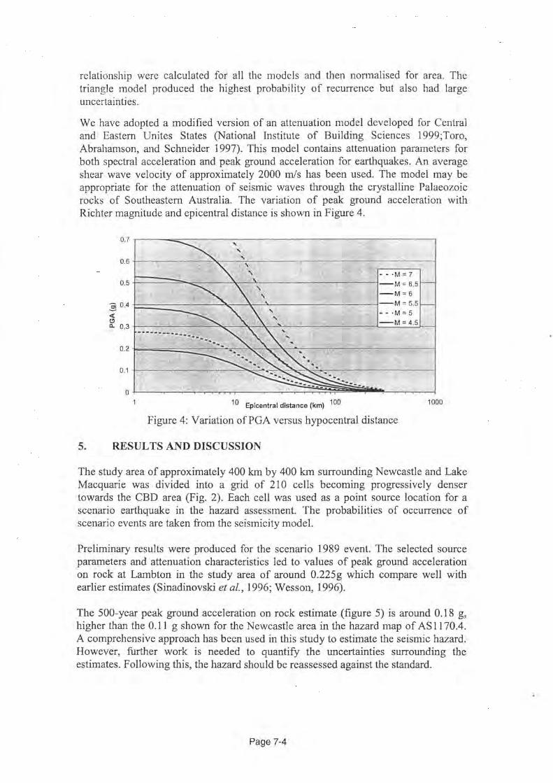
relationship were calculated for all the models and then nonnalised for area. The triangle model produced the highest probability of recurrence but also had large uncertainties.
We have adopted a modified version of an attenuation model developed for Central and Eastern Unites States (National Institute of Building Sciences 1999;Toro, Abrahamson, and Schneider 1997). This model contains attenuation parameters for both spectral acceleration and peak ground acceleration for earthquakes. An average shear wave velocity of approximately 2000 m/s has been used. The model may be appropriate for the attenuation of seismic waves through the crystalline Palaeozoic rocks of Southeastern Australia. The variation of peak ground acceleration with Richter magnitude and epicentral distance is shown in Figure 4.
0.7 '
0.6
0.5 ~====~~~--~~~--------~~~~~~--·M=7 + -M=6.5 -M=6
:§ 0.4 <(
F.=======----"'1.,--\c--~---;-=-----=-~-M = 5.5 - - ·M = 5
(.!) a. 0.3
-M=4.5
0.2
0.1
0 10 Epicentral distance (km) 100 1000
Figure 4: Variation ofPGA versus hypocentral distance
5. RESULTS AND DISCUSSION
The study area of approximately 400 km by 400 krn surrounding Newcastle and Lake Macquarie was divided into a grid of 210 cells becoming progressively denser towards the CBD area (Fig. 2). Each cell was used as a point source location for a scenario earthquake in the hazard assessment. The probabilities of occurrence of scenario events are taken from the seismicity model.
Preliminary results were produced for the scenario 1989 event. The selected source parameters and attenuation characteristics led to values of peak ground acceleration on rock at Lamb ton in the study area of around 0.225 g which compare well with earlier estimates (Sinadinovski et al., 1996; Wesson, 1996).
The 500-year peak ground acceleration on rock estimate (figure 5) is around 0.18 g, higher than the 0.11 g shown for the Newcastle area in the hazard map of AS 1170.4. A comprehensive approach has been used in this study to estimate the seismic hazard. However, further work is needed to quantify the uncertainties surrounding the estimates. Following this, the hazard should be reassessed against the standard.
Page 7-4

PGA500 0.16-0.17 0.17-0.18
•a/8-0.19 -0.19-0.20 ,;v Council bouruiary /v Mainroad
20246Kilo<mn:s ...... ~-
Figure 5: Peak Ground Acceleration hazard on rock for the study area (500-year)
6. REFERENCES
Chaytor, D.J., and Huftile, G.J., (2000) Faulting in the Newcastle area and its relationship to the 1989 M5.6 Newcastle earthquake. AEES seminar, Hobart, Nov. 2000.
Everingham, I. B., McEwin, A. J., & Denham, D., (1982) Atlas of isoseismal maps of Australian earthquakes. Bureau of Mineral Resources, Australia, Bulletin 214.
McCue, K., (Compiler) (1995) Atlas of isoseismal maps of Australian earthquakesPart 3. AGSO record 44.
McCue, K., Wesson, V. and Gibson, G. (1990) The Newcastle, New South Wales, earthquake of 28 December 1989. BMR Journal of Australian geology and Geophysics, Vol. 11, pp. 559-567.
Rynn, J.M.W., Denham, D., Greenhalgh, S.A., Jones, T., Gregson, P.J., McCue, K.F. and Smith, R.S., (1987) Atlas of isoseismal maps of Australian earthquakesPart 2. Bureau of Mineral Resources, Australia, Bulletin 222.
Sinadinovski, C., McCue, K,F., Somerville, M., Muirhead, T. and Muirhead, K. (1996) Simulation of Intra-plate Earthquakes in Australia using Green's Function Method: Sensitivity Study for Newcastle Event. AEES meeting, Adelaide, 1996.
Stehle, J., Jones, T. Stewart, D. and Corby, N. (2001) Vulnerability in the Newcastle region. AEES conference - Earthquake Codes in the Real World, Canberra 2001.
Wesson, V. (1996) Synthetic Ground Motion for the December 1989 Newcastle Earthquake. AEES meeting, Adelaide, 1996.
Page 7-5