seismic performance of rocking concrete shear walls with
TRANSCRIPT
Paper 0266
2019 Pacific Conference on Earthquake Engineering and Annual NZSEE Conference 1
Seismic Performance of Rocking Concrete Shear Walls with Innovative Rotational Resilient Slip Friction Joints
K. Sahami, S. Veismoradi & P. Zarnani Auckland University of Technology, Auckland, New Zealand.
P. Quenneville University of Auckland, Auckland, New Zealand.
ABSTRACT
With the prevalence of the concept of damage avoidance design, rocking walls were one of the primary solutions
to minimize structural components’ damage as well as decreasing the time and cost of building rehabilitation
after severe earthquakes. In this study, in order to achieve a self-centring damage avoidance rocking system, a
new generation of Rotational Resilient Slip Friction Joint (Rotational-RSFJ) has been employed as a shear link
between reinforced concrete shear walls and their boundary columns.
This type of friction damper dissipates energy through the rotational sliding of grooved surfaces pre-stressed
using disc springs, which can also provide the required self-centring to restore the building to its original position
without residual drifts. In this paper, initially the joint component has been analytically and numerically
investigated, and then the results have been used to develop an analytical model for the performance prediction
of the proposed rocking shear walls as a new lateral load resisting system. Such new self-centring system not
only does not require post-event maintenance, but also attenuates the complexity of analysing and implementing
of conventional resilient rocking walls using post-tensioning tendons.
Eventually, a five-story prototype building using the proposed lateral load resisting system comprising of single
and coupled rocking walls has been numerically analysed. Also, the effectiveness of such a concept has been
investigated for rocking systems with multiple ductile joints in different stories. The results demonstrated the
efficiency of the proposed system that is mainly attributed to high ductility, self-centring and the ability to
dissipate energy of Rotational-RSFJs.
Keywords: Rotational-RSFJ, Self-centring, Rocking shear wall, Energy dissipation, Low damage design
Paper 0266–Seismic Performance of Rocking Concrete Shear Wall with Innovative Rotational-RSFJ
2019 Pacific Conference on Earthquake Engineering and Annual NZSEE Conference 2
1 INTRODUCTION
Concrete shear walls due to their high seismic performance and cost-efficient material are vastly used in the
building industry. As shear walls provide sufficient resistance and stiffness, this lateral load resisting system
rarely had experienced collapse during an earthquake, but various degree of structural and non-structural
damages were reported, which caused significant property losses, including connection to floors and
foundation(Fintel 1995). In conventional design approach, engineers provide the required ductility by material
nonlinearity which means accepting possible residual drift and damage in buildings after severe events.
Therefore, such structures need post event repairing. The first studies of rocking motion were based on
investigation of overturning resistance of a rigid body, which proved that a rocking block is capable to rebound
till the center of gravity does not reach the edge of foundation (Muto K 1960). The concept of rocking structures
as a resisting system against lateral forces was initially introduced by Housner (1963). Aslam (1978) proposed
adding post-tensioning mechanism in order to provide self-centring capability for rocking systems. Later,
Priestley (1995) with the aim of elimination of residual drift, conducted a series of non-linear dynamic time
history analyses for moment resisting structures equipped by prestressing tendons. Through further research,
Stone et al. (1995) introduced a hybrid system, which incorporated mild steel reinforcement for dissipating
energy along with self-centring mechanism provided by unbonded post-tensioned tendons. Also, following the
PREcast Seismic Structural Systems (PRESSS) research program (Priestley 1991), several prestressed frames
were developed in the United States to achieve a self-centring system with minimum damage and residual drift.
Employing unbonded post-tensioning to tie precast components together was the main feature of the PRESSS
program, including in beam-to-column connections and shear walls. Another factor that significantly affects the
structural response during a cyclic loading is the capacity to dissipate the energy, which traditionally was
provided by nonlinear behaviour of material in the structure. As for rocking structures, following the onset of
low damage concepts, while the tendons were designed to remain elastic, the structure was equipped with
additional devices to be able to dissipate the earthquake energy. As part of PRESSS program, for coupled wall
systems, various kinds of shear connectors such as U-shaped flexural plates (UFPs) were used to transfer the
shear force and also dissipate input energy (Priestley et al. 1999). Providing necessary damping for a rocking
system was the centre of attention for a number of researches. Marriott (2008) proposed viscous fluid dampers
or tension-compression yielding steel dampers externally located in parallel to post-tensioned tendons.
Buckling-Restrained Braces (BRB) also had been proposed to be used in Propped Rocking Wall Systems
(Nicknam 2015). However, all mentioned rocking shear wall systems benefited PT systems for providing
restoring force and require additional kind of passive damper as a sacrificial element to dissipate energy. As
prestressing plays an important role in such systems, prestressing loss adversely affects the overall performance.
Creeping, vulnerability against ambient factors such as temperature along with practical challenges of
installation, especially for tall shear walls, could be pointed as the challenges of PT. Zarnani and Quenneville
(2015) introduced a new generation of friction damper which provides restoring force and energy dissipation
combined in one compact joint. Such resilient slip friction joint (RFSJ) was initially studied in a rocking timber
wall application as a hold-down (Hashemi et al. 2017), which later was employed in a practical project (Nelson
airport terminal, NZ). Darani et al. (2018) extended this concept to rocking concrete shear walls as a damage
free solution with no service or post-event maintenance. In this paper, an innovative seismic device branded as
Rotational Resilient Slip Friction Joint (Rotational-RSFJ) to be considered as a new generation of RSFJ - has
been developed. R-RSFJ has the same concept of RSFJ for providing self-centring and damage avoidance
characteristics, however it benefits from rotational movement like the common Rotational Damper (Mualla et
al. 2002), which significantly enhances its deflection capacity. Such features, make it possible for R-RSFJ to be
incorporated to rocking shear walls to present a damage free resisting system. By adopting the R-RSFJs as shear
links between reinforced concrete shear walls and their boundary columns, the resisting force will be distributed
along the wall resulting in reduction of bending moment demand. This not only avoids high-stress concentration
at the conventional hold-down connections, but also reduces the wall size significantly.
Paper 0266–Seismic Performance of Rocking Concrete Shear Wall with Innovative Rotational-RSFJ
2019 Pacific Conference on Earthquake Engineering and Annual NZSEE Conference 3
2 ROTATIONAL RESILIENT SLIP FRICTION JOINT (R-RSFJ)
2.1 Analytical modelling of Rotational-RSF joint
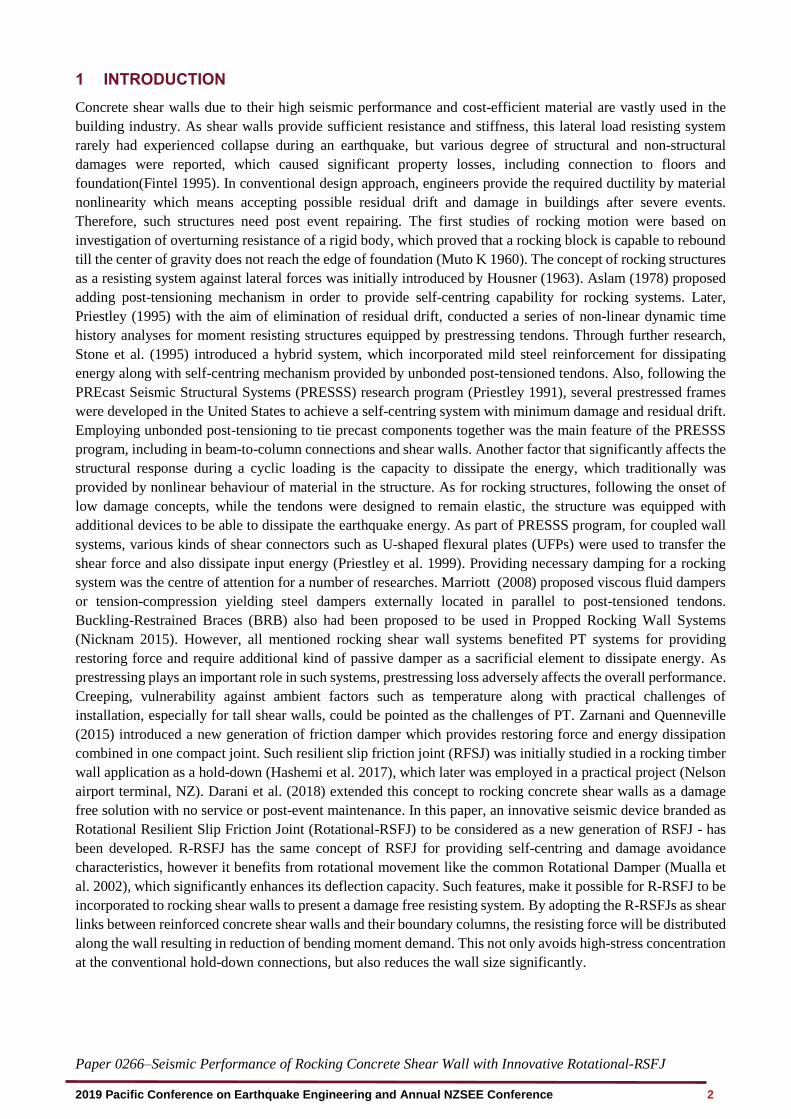
The mechanical mechanism of Rotational-RSFJ is similar to RSFJ. In both devices, the restoring force comes
from a specific steel grooved plates which are tied through high strength bolts and disk springs. By slipping of
grooved plates, the input energy is dissipated through frictional resistance. Based on the free body diagrams
presented in Fig. 1, the design procedure is developed for the prediction of the performance of the RSF joint
(Hashemi et al. 2017). The slip force (Fslip) and residual force (Fres) can be determined by Eq. (1) and Eq. (2):
, ,
sin cos2
cos sin
s
RSFJ slip b b pr
s
F n F
+=
−
(1)
, ,
sin cos2
cos sin
k
RSFJ res b b pr
k
F n F
−=
+
(2)
Where nb=number of bolts on each splice, θ=groove angle, Fb.pr is clamping force of pre- stressing and the μs
and μk are the static and kinetic coefficient of friction respectively, while considered μk=0.85μs (Hashemi,
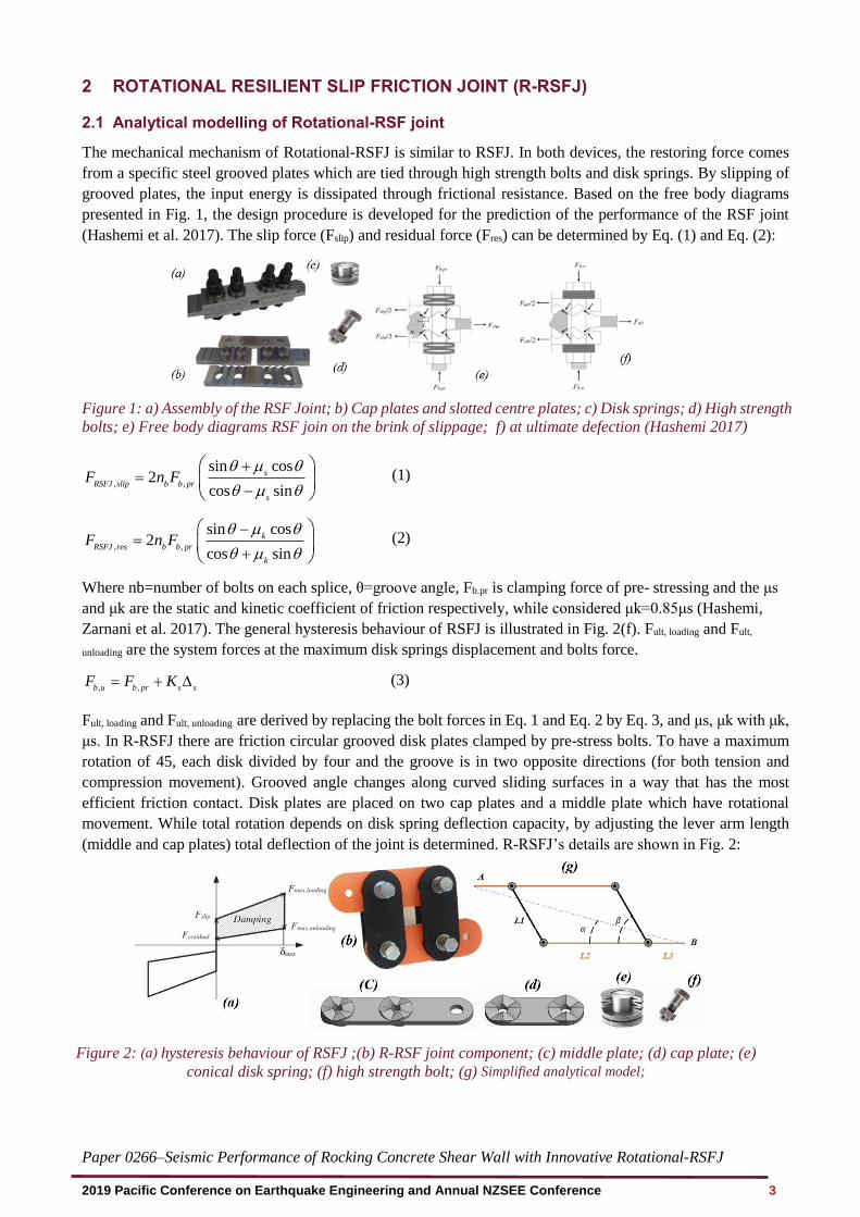
Zarnani et al. 2017). The general hysteresis behaviour of RSFJ is illustrated in Fig. 2(f). Fult, loading and Fult,
unloading are the system forces at the maximum disk springs displacement and bolts force.
, ,b u b pr s sF F K= + (3)
Fult, loading and Fult, unloading are derived by replacing the bolt forces in Eq. 1 and Eq. 2 by Eq. 3, and μs, μk with μk,
μs. In R-RSFJ there are friction circular grooved disk plates clamped by pre-stress bolts. To have a maximum
rotation of 45, each disk divided by four and the groove is in two opposite directions (for both tension and
compression movement). Grooved angle changes along curved sliding surfaces in a way that has the most
efficient friction contact. Disk plates are placed on two cap plates and a middle plate which have rotational
movement. While total rotation depends on disk spring deflection capacity, by adjusting the lever arm length
(middle and cap plates) total deflection of the joint is determined. R-RSFJ’s details are shown in Fig. 2:
Figure 2: (a) hysteresis behaviour of RSFJ ;(b) R-RSF joint component; (c) middle plate; (d) cap plate; (e)
conical disk spring; (f) high strength bolt; (g) Simplified analytical model;
Figure 1: a) Assembly of the RSF Joint; b) Cap plates and slotted centre plates; c) Disk springs; d) High strength
bolts; e) Free body diagrams RSF join on the brink of slippage; f) at ultimate defection (Hashemi 2017)
Paper 0266–Seismic Performance of Rocking Concrete Shear Wall with Innovative Rotational-RSFJ
2019 Pacific Conference on Earthquake Engineering and Annual NZSEE Conference 4
L1 is the length of middle plates and L2 denotes the distance between two cap plates, so L2+L3 denotes the
length of cap plates. β and α are the angle between the cap and middle plates and the angle of applied load,
respectively. By measuring the changes in α and β, total deflection can be calculated:
3 2 12 cos( )
cos( )
L L LL
+ += (4)
Where the parameter α can be obtained by:
1
3 2 1
sin( )Arctan
2 cos( )
L
L L L
=
+ +
(5)
So, the deflection and the joint force in each step are derived by is expressed by Eq. 6 and Eq. 7.
iniL L = − (6)
3 2
4
(2 )sin( )
MF
L L =
+ (7)
2.2 Numerical modelling of Rotational-RSF joint
In order to have a comparison between the analytical result and FE analysis, the behaviour of a joint component
has been studied using the FE analysis software, Abaqus. The properties of the analysed joint are summarised
in Table 1.
Table 1. Rotational-RSFJ characteristics
Parameter Value
Cap plate thickness (mm) 12
Middle plate thickness (mm) 20
β (degree) 108
Friction Disk diameter (mm) 125
Pin hole diameter (mm) 36
Coefficient of Friction 0.18
Disk spring ultimate force (KN) 132
Disk spring deflection capacity (mm) 1.75
No. of disk spring per bolt per side 9
For the cap plates and middle plates, high strength steel
(Fy=690MPa and Fu=860MPa) with deformable solid
parts (meshed by C3D8R finite element) were used.
The friction coefficient considered to be the same value
of μ=0.18 for static and kinetic conditions and contact
is modelled with the "Hard contact" normal behaviour
along with tangential behaviour with relative sliding.
The rods and the stack are also assumed as a spring.
Force was inserted in two steps: (i) disk spring pre-
stressing force, (ii) displacement history application.
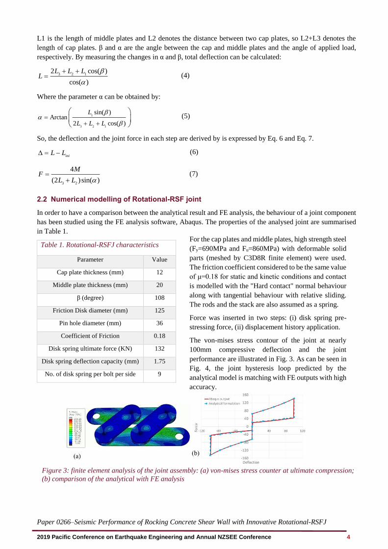
The von-mises stress contour of the joint at nearly
100mm compressive deflection and the joint
performance are illustrated in Fig. 3. As can be seen in
Fig. 4, the joint hysteresis loop predicted by the
analytical model is matching with FE outputs with high
accuracy.
Figure 3: finite element analysis of the joint assembly: (a) von-mises stress counter at ultimate compression;
(b) comparison of the analytical with FE analysis
Paper 0266–Seismic Performance of Rocking Concrete Shear Wall with Innovative Rotational-RSFJ
2019 Pacific Conference on Earthquake Engineering and Annual NZSEE Conference 5
3 ROCKING WALL EQUIPPED ROTATIONAL RSF JOINT
All rocking systems need to have a hold-down together with dissipating mechanism to reach to desired level of
seismic performance. In conventional rocking shear walls, to satisfy mentioned conditions, PT tendons with a
kind of sacrificial element for dissipating input energy are employed. However, apart from unbonded post-
tensioning implementation complexity, especially for tall shear walls, loss of tension in strands, always has been
a concern for engineers. Also, systems with yielding mechanism are vulnerable against severe aftershocks. So,
such systems require to have particular inspection and maintenance after event. The rotational movement and
high deflection capacity of R-RSFJ make it possible that this joint being used with boundary column to provide
structures with sufficient restoring force as well as damping mechanism simultaneously, which eliminates the
need of regular inspections and post-event maintenance.
3.1 Single rocking shear wall equipped with R-RSFJs and end columns
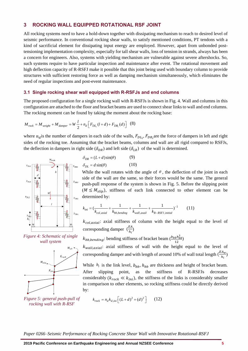
The proposed configuration for a single rocking wall with R-RSFJs is shown in Fig. 4. Wall and columns in this
configuration are attached to the floor and bracket beams are used to connect shear links to wall and end columns.
The rocking moment can be found by taking the moment about the rocking base:
( ) ( )2 i irock weight damper d DL DR
lM M M W n F l d F d = + = + + +
(8)
where 𝑛𝑑is the number of dampers in each side of the walls, 𝐹𝐷𝐿𝑖, 𝐹𝐷𝑅𝑖
are the force of dampers in left and right
sides of the rocking toe. Assuming that the bracket beams, columns and wall are all rigid compared to RSFJs,
the deflection in dampers in right side (𝛿𝐷𝑅) and left side (𝛿𝐿𝑅) of the wall is determined.
( )sin( )DR L d = + (9)
sin( )DL d = (10)
While the wall rotates with the angle of , the deflection of the joint in each
side of the wall are the same, so their forces would be the same. The general
push-pull response of the system is shown in Fig. 5. Before the slipping point
(𝑀 ≤ 𝑀𝑠𝑙𝑖𝑝), stiffness of each link connected to other element can be
determined by:
1
, , , ,
1 1 1 1( )ini
col axial bb bending wall axail R RSFJ initial
kk k k k
−
−
= + + + (11)
𝑘𝑐𝑜𝑙,𝑎𝑥𝑖𝑎𝑙: axial stiffness of column with the height equal to the level of
corresponding damper (𝐸𝐴
ℎ𝑖)
𝑘𝑏𝑏,𝑏𝑒𝑛𝑑𝑖𝑛𝑔: bending stiffness of bracket beam (𝑏𝑏𝑏ℎ𝑏𝑏
3
12)
𝑘𝑤𝑎𝑙𝑙,𝑎𝑥𝑖𝑎𝑙: axial stiffness of wall with the height equal to the level of
corresponding damper and with length of around 10% of wall total length (𝐸𝐴𝑤
ℎ𝑖)
While ih is the link level, 𝑏𝑏𝑏, ℎ𝑏𝑏 are thickness and height of bracket beam.
After slipping point, as the stiffness of R-RSFJs decreases
considerably (𝑘𝑟𝑜𝑐𝑘 ≪ 𝑘𝑖𝑛𝑖), the stiffness of the links is considerably smaller
in comparison to other elements, so rocking stiffness could be directly derived
by:
2 2, ( ) ( )rock d d inik n k L d d = + +
(12)
Figure 4: Schematic of single
wall system
Figure 5: general push-pull of
rocking wall with R-RSF
joints
Paper 0266–Seismic Performance of Rocking Concrete Shear Wall with Innovative Rotational-RSFJ
2019 Pacific Conference on Earthquake Engineering and Annual NZSEE Conference 6
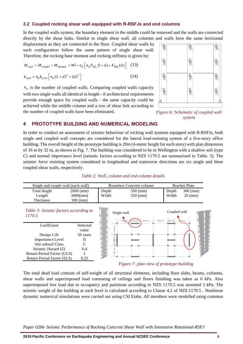
3.2 Coupled rocking shear wall equipped with R-RSFJs and end columns
In the coupled walls system, the boundary element in the middle could be removed and the walls are connected
directly by the shear links. Similar to single shear wall, all columns and walls have the same horizontal
displacement as they are connected to the floor. Coupled shear walls by
such configuration follow the same pattern of single shear wall.
Therefore, the rocking base moment and rocking stiffness is given by:
( ) ( )i irock weight damper d w DL DRM M M Wl n n F l d F d = + = + + +
(13)
2 2, ( ) ( )rock d d ini wk n k n L d d = + +
(14)
wn is the number of coupled walls. Comparing coupled walls capacity
with two single walls all identical in length - if architectural requirements
provide enough space for coupled walls - the same capacity could be
achieved while the middle column and a row of shear link according to
the number of coupled walls have been eliminated.
4 PROTOTYPE BUILDING AND NUMERICAL MODELING
In order to conduct an assessment of seismic behaviour of rocking wall systems equipped with R-RSFJs, both
single and coupled wall concepts are considered for the lateral load-resisting system of a five-story office
building. The overall height of the prototype building is 20m (4-meter height for each story) with plan dimension
of 16 m by 32 m, as shown in Fig. 7. The building was considered to be in Wellington with a shallow soil (type
C) and normal importance level (seismic factors according to NZS 1170.5 are summarised in Table. 3). The
seismic force resisting system considered in longitudinal and transverse directions are six single and three
coupled shear walls, respectively.
Table 2: Wall, column and end column details
Single and couple wall (each wall) Boundary Concrete column Bracket Plate
Total height 2000 (mm) Depth 350 (mm) Depth 300 (mm)
Length 3000(mm) Width 350 (mm) Width 20 (mm)
Thickness 300 (mm)
Figure 7: plan view of prototype building
The total dead load consists of self-weight of all structural elements, including floor slabs, beams, columns,
shear walls and superimposed load consisting of ceilings and floors finishing was taken as 6 kPa. Also
superimposed live load due to occupancy and partitions according to NZS 1170.5 was assumed 3 kPa. The
seismic weight of the building at each level is calculated according to Clause 4.2 of NZS.1170.5 . Nonlinear
dynamic numerical simulations were carried out using CSI Etabs. All members were modelled using common
Table 3: Seismic factors according to NZS
1170.5
Coefficient Selected
value
Design Life 50 years
Importance Level II
Site subsoil Class C
Seismic Hazard (Z) 0.4
Return Period Factor (ULS) 1
Return Period Factor (SLS) 0.25
Figure 6: Schematic of coupled wall
system
Coupled wall Single wall
Paper 0266–Seismic Performance of Rocking Concrete Shear Wall with Innovative Rotational-RSFJ
2019 Pacific Conference on Earthquake Engineering and Annual NZSEE Conference 7
frame and shells elements. The Rotational-RSF joints were modelled by a Damper – Friction spring link element
which is available in CSI Etabs. For the base connections and shear keys, which transfer shear forces to the
foundation, nonlinear gap link with a high compressive stiffness and zero gap was employed. Columns and
beams in this model were considered to resist gravity load, so connections of beams to columns and columns to
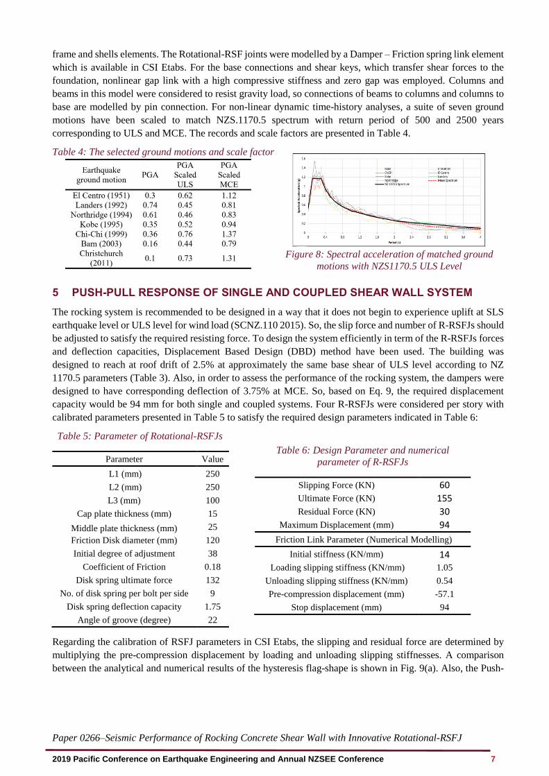
base are modelled by pin connection. For non-linear dynamic time-history analyses, a suite of seven ground
motions have been scaled to match NZS.1170.5 spectrum with return period of 500 and 2500 years
corresponding to ULS and MCE. The records and scale factors are presented in Table 4.
Table 4: The selected ground motions and scale factor
Figure 8: Spectral acceleration of matched ground
motions with NZS1170.5 ULS Level
5 PUSH-PULL RESPONSE OF SINGLE AND COUPLED SHEAR WALL SYSTEM
The rocking system is recommended to be designed in a way that it does not begin to experience uplift at SLS
earthquake level or ULS level for wind load (SCNZ.110 2015). So, the slip force and number of R-RSFJs should
be adjusted to satisfy the required resisting force. To design the system efficiently in term of the R-RSFJs forces
and deflection capacities, Displacement Based Design (DBD) method have been used. The building was
designed to reach at roof drift of 2.5% at approximately the same base shear of ULS level according to NZ
1170.5 parameters (Table 3). Also, in order to assess the performance of the rocking system, the dampers were
designed to have corresponding deflection of 3.75% at MCE. So, based on Eq. 9, the required displacement
capacity would be 94 mm for both single and coupled systems. Four R-RSFJs were considered per story with
calibrated parameters presented in Table 5 to satisfy the required design parameters indicated in Table 6:
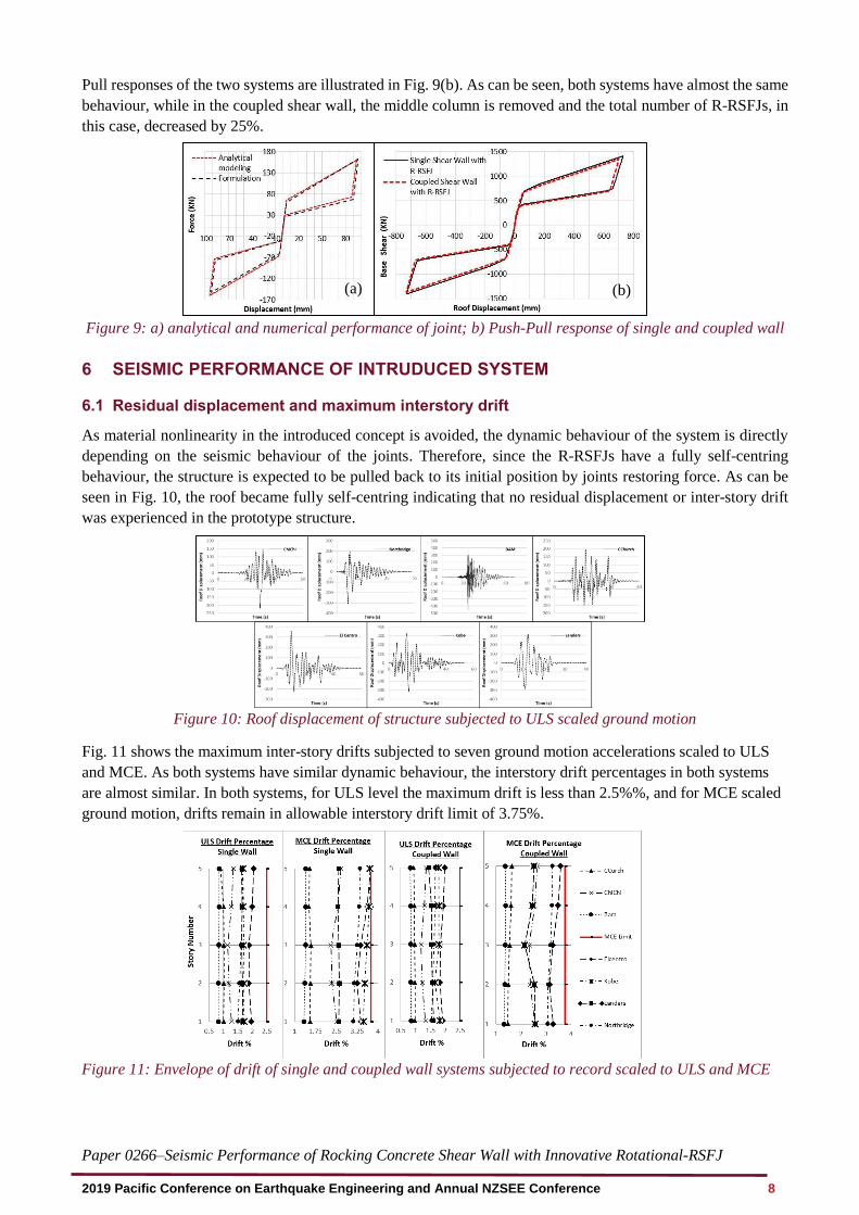
Regarding the calibration of RSFJ parameters in CSI Etabs, the slipping and residual force are determined by
multiplying the pre-compression displacement by loading and unloading slipping stiffnesses. A comparison
between the analytical and numerical results of the hysteresis flag-shape is shown in Fig. 9(a). Also, the Push-
Table 5: Parameter of Rotational-RSFJs
Parameter Value
L1 (mm) 250
L2 (mm) 250
L3 (mm) 100
Cap plate thickness (mm) 15
Middle plate thickness (mm) 25
Friction Disk diameter (mm) 120
Initial degree of adjustment 38
Coefficient of Friction 0.18
Disk spring ultimate force 132
No. of disk spring per bolt per side 9
Disk spring deflection capacity 1.75
Angle of groove (degree) 22
Table 6: Design Parameter and numerical
parameter of R-RSFJs
Slipping Force (KN) 60
Ultimate Force (KN) 155
Residual Force (KN) 30
Maximum Displacement (mm) 94
Friction Link Parameter (Numerical Modelling)
Initial stiffness (KN/mm) 14 Loading slipping stiffness (KN/mm) 1.05
Unloading slipping stiffness (KN/mm) 0.54
Pre-compression displacement (mm) -57.1
Stop displacement (mm) 94
Paper 0266–Seismic Performance of Rocking Concrete Shear Wall with Innovative Rotational-RSFJ
2019 Pacific Conference on Earthquake Engineering and Annual NZSEE Conference 8
Pull responses of the two systems are illustrated in Fig. 9(b). As can be seen, both systems have almost the same
behaviour, while in the coupled shear wall, the middle column is removed and the total number of R-RSFJs, in
this case, decreased by 25%.
Figure 9: a) analytical and numerical performance of joint; b) Push-Pull response of single and coupled wall
6 SEISMIC PERFORMANCE OF INTRUDUCED SYSTEM
6.1 Residual displacement and maximum interstory drift
As material nonlinearity in the introduced concept is avoided, the dynamic behaviour of the system is directly
depending on the seismic behaviour of the joints. Therefore, since the R-RSFJs have a fully self-centring
behaviour, the structure is expected to be pulled back to its initial position by joints restoring force. As can be
seen in Fig. 10, the roof became fully self-centring indicating that no residual displacement or inter-story drift
was experienced in the prototype structure.
Figure 10: Roof displacement of structure subjected to ULS scaled ground motion
Fig. 11 shows the maximum inter-story drifts subjected to seven ground motion accelerations scaled to ULS
and MCE. As both systems have similar dynamic behaviour, the interstory drift percentages in both systems
are almost similar. In both systems, for ULS level the maximum drift is less than 2.5%%, and for MCE scaled
ground motion, drifts remain in allowable interstory drift limit of 3.75%.
Figure 11: Envelope of drift of single and coupled wall systems subjected to record scaled to ULS and MCE
(a) (b)
Paper 0266–Seismic Performance of Rocking Concrete Shear Wall with Innovative Rotational-RSFJ
2019 Pacific Conference on Earthquake Engineering and Annual NZSEE Conference 9
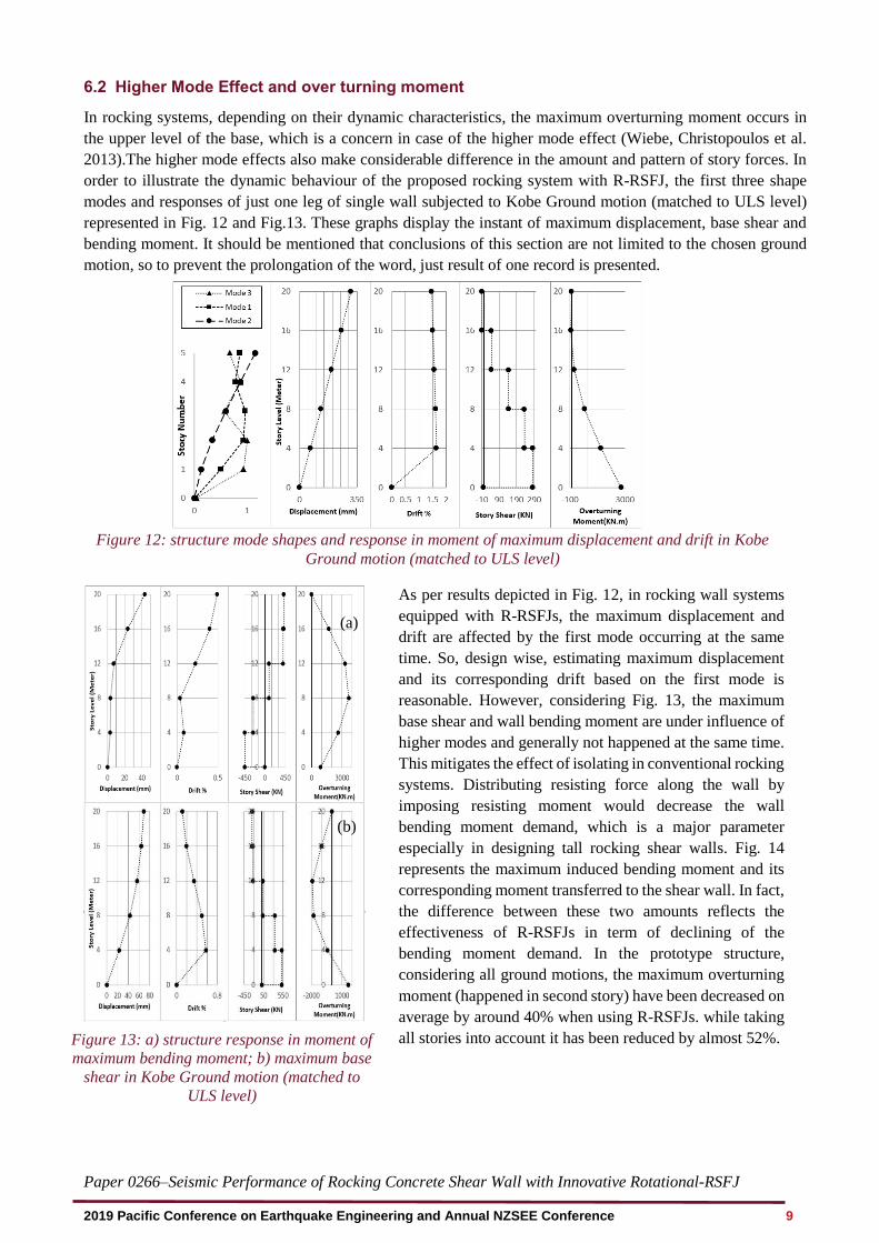
6.2 Higher Mode Effect and over turning moment
In rocking systems, depending on their dynamic characteristics, the maximum overturning moment occurs in
the upper level of the base, which is a concern in case of the higher mode effect (Wiebe, Christopoulos et al.
2013).The higher mode effects also make considerable difference in the amount and pattern of story forces. In
order to illustrate the dynamic behaviour of the proposed rocking system with R-RSFJ, the first three shape
modes and responses of just one leg of single wall subjected to Kobe Ground motion (matched to ULS level)
represented in Fig. 12 and Fig.13. These graphs display the instant of maximum displacement, base shear and
bending moment. It should be mentioned that conclusions of this section are not limited to the chosen ground
motion, so to prevent the prolongation of the word, just result of one record is presented.
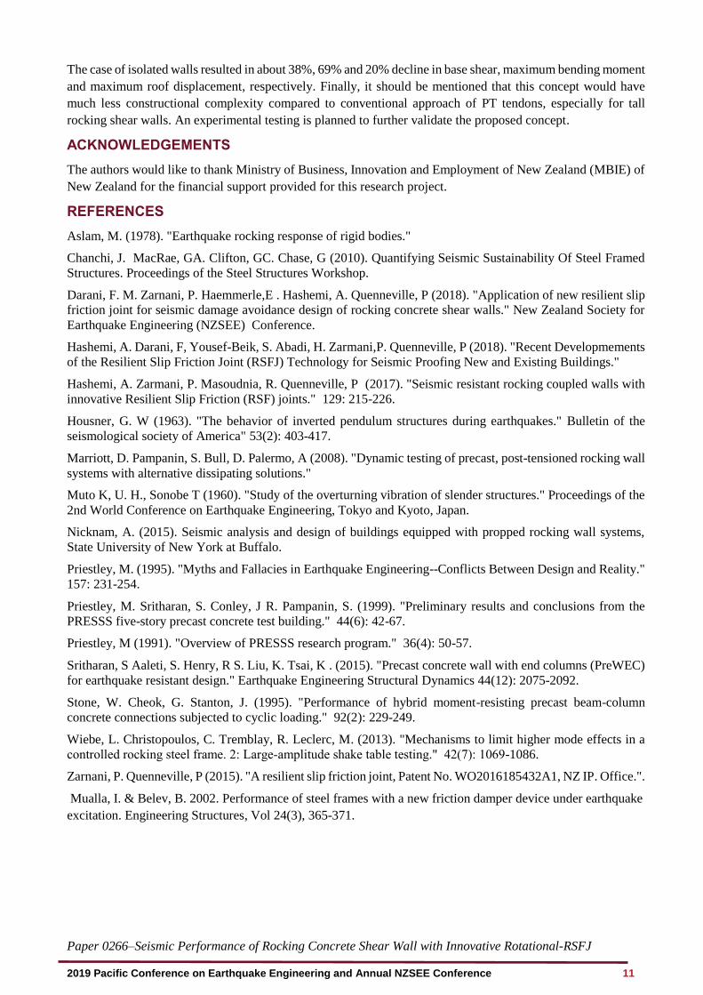
Figure 13: a) structure response in moment of
maximum bending moment; b) maximum base
shear in Kobe Ground motion (matched to
ULS level)
Figure 12: structure mode shapes and response in moment of maximum displacement and drift in Kobe
Ground motion (matched to ULS level)
(b)
(a)
As per results depicted in Fig. 12, in rocking wall systems
equipped with R-RSFJs, the maximum displacement and
drift are affected by the first mode occurring at the same
time. So, design wise, estimating maximum displacement
and its corresponding drift based on the first mode is
reasonable. However, considering Fig. 13, the maximum
base shear and wall bending moment are under influence of
higher modes and generally not happened at the same time.
This mitigates the effect of isolating in conventional rocking
systems. Distributing resisting force along the wall by
imposing resisting moment would decrease the wall
bending moment demand, which is a major parameter
especially in designing tall rocking shear walls. Fig. 14
represents the maximum induced bending moment and its
corresponding moment transferred to the shear wall. In fact,
the difference between these two amounts reflects the
effectiveness of R-RSFJs in term of declining of the
bending moment demand. In the prototype structure,
considering all ground motions, the maximum overturning
moment (happened in second story) have been decreased on
average by around 40% when using R-RSFJs. while taking
all stories into account it has been reduced by almost 52%.

Paper 0266–Seismic Performance of Rocking Concrete Shear Wall with Innovative Rotational-RSFJ
2019 Pacific Conference on Earthquake Engineering and Annual NZSEE Conference 10
Figure 14: maximum induced overturning moment and it’s decreased amount due to R-RSFJs
6.3 Multiple Rocking Sections
One of the approaches to mitigate higher mode effects in rocking system is using multiple rocking joints (Wiebe,
Christopoulos et al. 2013). Such concept even has been used in a practical project, which RSFJs had been used
as hold-downs in base and mid-height of timber walls (Hashemi, Darani et al. 2018). Given the fact that the R-
RSFJs are placed along the wall in all stories, the wall could be separated in each story level. The connection
between isolated walls would have the similar mechanism of base joints, in which connection lets rotational
movement while transmits the shear force to the lower level. So, as to study the effectiveness of such approach,
the wall in single wall system is separated at all story levels. The mean value of maximum base shear, bending
moment and displacement, subjected to the selected ground motions are illustrated in Fig. 15. It should be noted
that the bending moment is the moment demand in one span of single wall system. Regarding the base shear,
the results show on average a 38% decline. In
term of overturning moment, the maximum
overturning moment in the second story was
decreased by about 69%, while considering all
story, this reduction was nearly 62%. The
stories displacement also decreased by around
20%. Eliminating the higher mode effect,
together with softening the structure which
leads to decreasing input energy (through the
isolating shear walls in each story) led to a
reduction in base shear, overturning moment
and even story displacement of such system.
7 SUMMERY AND CONCLUSION
In this paper, a new generation of rotational self-centring friction damper has been introduced and its
performance analytically and numerically investigated. This innovative Rotational Resilient Slip Friction Joint
(R-RSFJ) was incorporated in a rocking shear wall system with the aim of achieving a damage avoidance
resisting system. Such system with boundary columns could be used for a single or coupled shear walls. In this
concept, Rotational-RSF joints act as shear links as well as energy dissipation devices. To evaluate the seismic
performance of such system, a five-story prototype building with single and coupled rocking shear walls
equipped with RSFJs has been analysed. The results of time history analysis of the structure subjected to seven
ground motions confirm the efficiency of the proposed system in terms of fully self-centring of the structure and
satisfying the interstory drift limit of ULS and MCE, as well as considerable reduction of the maximum bending
demands. Also, the possibility of isolating the walls in stories to mitigate higher mode effects was investigated.
Figure 15: The mean value of maximum base shear,
bending moment and displacement of single wall system
Paper 0266–Seismic Performance of Rocking Concrete Shear Wall with Innovative Rotational-RSFJ
2019 Pacific Conference on Earthquake Engineering and Annual NZSEE Conference 11
The case of isolated walls resulted in about 38%, 69% and 20% decline in base shear, maximum bending moment
and maximum roof displacement, respectively. Finally, it should be mentioned that this concept would have
much less constructional complexity compared to conventional approach of PT tendons, especially for tall
rocking shear walls. An experimental testing is planned to further validate the proposed concept.
ACKNOWLEDGEMENTS
The authors would like to thank Ministry of Business, Innovation and Employment of New Zealand (MBIE) of
New Zealand for the financial support provided for this research project.
REFERENCES
Aslam, M. (1978). "Earthquake rocking response of rigid bodies."
Chanchi, J. MacRae, GA. Clifton, GC. Chase, G (2010). Quantifying Seismic Sustainability Of Steel Framed
Structures. Proceedings of the Steel Structures Workshop.
Darani, F. M. Zarnani, P. Haemmerle,E . Hashemi, A. Quenneville, P (2018). "Application of new resilient slip
friction joint for seismic damage avoidance design of rocking concrete shear walls." New Zealand Society for
Earthquake Engineering (NZSEE) Conference.
Hashemi, A. Darani, F, Yousef-Beik, S. Abadi, H. Zarmani,P. Quenneville, P (2018). "Recent Developmements
of the Resilient Slip Friction Joint (RSFJ) Technology for Seismic Proofing New and Existing Buildings."
Hashemi, A. Zarmani, P. Masoudnia, R. Quenneville, P (2017). "Seismic resistant rocking coupled walls with
innovative Resilient Slip Friction (RSF) joints." 129: 215-226.
Housner, G. W (1963). "The behavior of inverted pendulum structures during earthquakes." Bulletin of the
seismological society of America" 53(2): 403-417.
Marriott, D. Pampanin, S. Bull, D. Palermo, A (2008). "Dynamic testing of precast, post-tensioned rocking wall
systems with alternative dissipating solutions."
Muto K, U. H., Sonobe T (1960). "Study of the overturning vibration of slender structures." Proceedings of the
2nd World Conference on Earthquake Engineering, Tokyo and Kyoto, Japan.
Nicknam, A. (2015). Seismic analysis and design of buildings equipped with propped rocking wall systems,
State University of New York at Buffalo.
Priestley, M. (1995). "Myths and Fallacies in Earthquake Engineering--Conflicts Between Design and Reality."
157: 231-254.
Priestley, M. Sritharan, S. Conley, J R. Pampanin, S. (1999). "Preliminary results and conclusions from the
PRESSS five-story precast concrete test building." 44(6): 42-67.
Priestley, M (1991). "Overview of PRESSS research program." 36(4): 50-57.
Sritharan, S Aaleti, S. Henry, R S. Liu, K. Tsai, K . (2015). "Precast concrete wall with end columns (PreWEC)
for earthquake resistant design." Earthquake Engineering Structural Dynamics 44(12): 2075-2092.
Stone, W. Cheok, G. Stanton, J. (1995). "Performance of hybrid moment-resisting precast beam-column
concrete connections subjected to cyclic loading." 92(2): 229-249.
Wiebe, L. Christopoulos, C. Tremblay, R. Leclerc, M. (2013). "Mechanisms to limit higher mode effects in a
controlled rocking steel frame. 2: Large‐amplitude shake table testing." 42(7): 1069-1086.
Zarnani, P. Quenneville, P (2015). "A resilient slip friction joint, Patent No. WO2016185432A1, NZ IP. Office.".
Mualla, I. & Belev, B. 2002. Performance of steel frames with a new friction damper device under earthquake
excitation. Engineering Structures, Vol 24(3), 365-371.