seismic performance of timber-steel hybrid structuresrisedr.tongji.edu.cn/ubc/ppt/5.5/plenary...
TRANSCRIPT

Zheng Li
PhD, Assistant Professor
Department of Structural Engineering
Tongji University
Seismic Performance of Timber-Steel
Hybrid Structures
The Fifth Tongji-UBC Symposium on Earthquake Engineering
"Facing Earthquake Challenges Together”

Outline
1. Introduction
2. Timber-steel hybrid structure
3. Experimental study
4. Numerical modeling
5. Reliability analysis
6. Summary

1. Introduction
Earthquakes!

1. Introduction
Christchurch earthquake, M6.3, New Zealand, 2011,
Photo by A. Trafford
Wenchuan earthquake, M8.0, China, 2008
Wenchuan earthquake, M8.0, China, 2008
Kobe earthquake, M6.9, Japan, 1995,
Photo by M.Yasumura

Murray Grove 8-storey CLT structure
in London (2008)
10-storey CLT structure
in Melbourne (2012)
Timber-concrete hybrid building in Quebec City
(2010)
Examples of multi-storey
timber buildings
1. Introduction
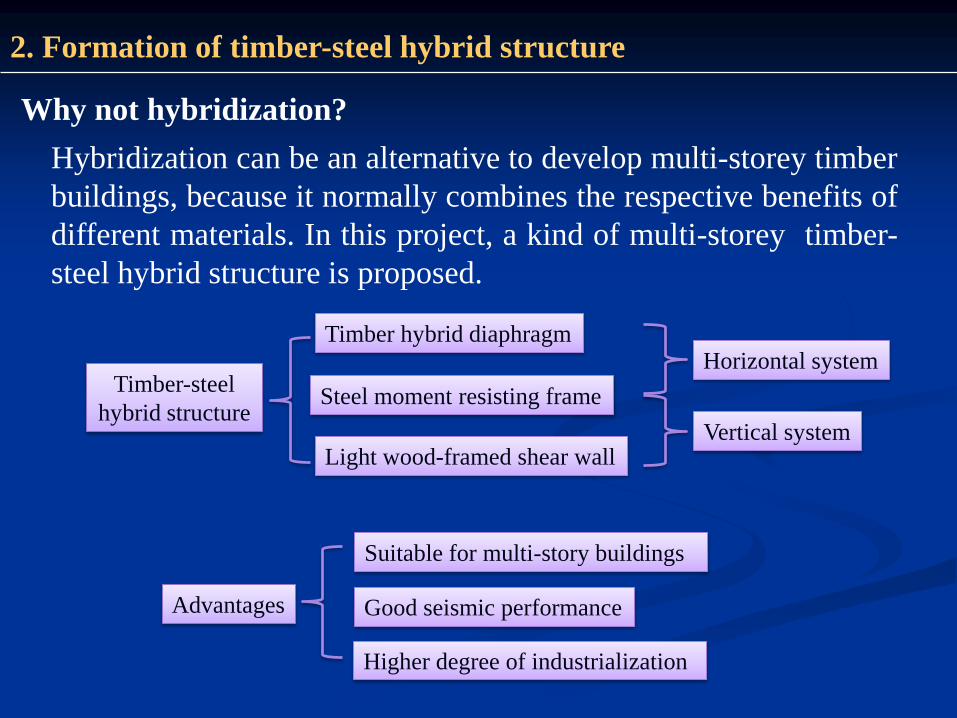
2. Formation of timber-steel hybrid structure
Why not hybridization?
Hybridization can be an alternative to develop multi-storey timber
buildings, because it normally combines the respective benefits of
different materials. In this project, a kind of multi-storey timber-
steel hybrid structure is proposed.
Timber-steel
hybrid structure
Timber hybrid diaphragm
Steel moment resisting frame
Suitable for multi-story buildings
Good seismic performance
Higher degree of industrialization
Advantages
Light wood-framed shear wall
Horizontal system
Vertical system

Steel frame
Infill wood-framed shear wall
Bolts
Anchor bolts
Hold-down
Timber-steel hybrid shear wall system
2. Formation of timber-steel hybrid structure

Specimen A :
light wood-framed diaphragm
single-sheathed infill wood-
framed shear wall
Specimen B:
Timber-steel hybrid diaphragm
double-sheathed infill wood-
framed shear wall
A-1, A-2, A-3 and B-1, B-2, B-3
are timber-steel hybrid shear
wall systems in specimen A and
specimen B.
3.1 Specimen design
3. Experimental study
Layout of specimen A and specimen B

Specimen A
(light wood-framed diaphragm &
single-sheathed infill wood shear wall)
Specimen B
(timber-steel hybrid diaphragm &
double-sheathed infill wood shear wall )
3. Experimental study
3.3 Installation of the specimen

The specimens were first subjected to non-destructive monotonic load to
study the initial lateral stiffness of the steel frame before and after the
installation of infills. Then fully reversed quasi-static cyclic load was
applied and cycled to 80% of degradation in the specimen’s strength.
3. Experimental study
3.4 Test Procedures

Nail heads embedding into
the sheathing panels
Failure of weld
• Failure modes
3. Experimental study
After the tests
Fatigue fracture of nails
Fall off of the
sheathing panels

(a) A-1 (c) A-3(b) A-2
• Hysteresis loops
(d) B-1 (f) B-3(e) B-2
3. Experimental study
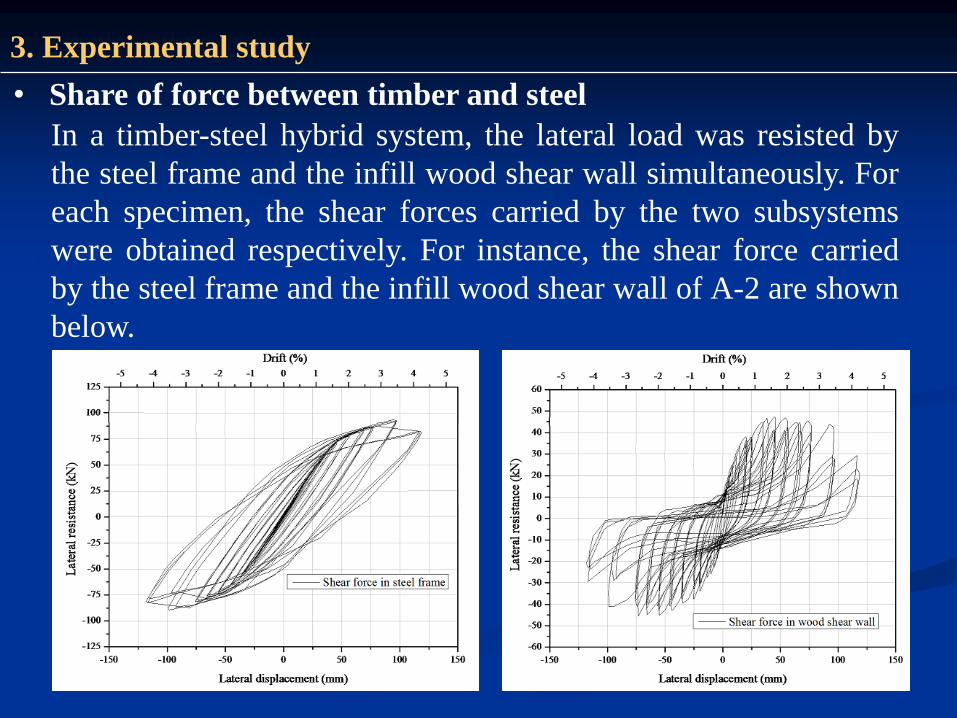
• Share of force between timber and steel
In a timber-steel hybrid system, the lateral load was resisted by
the steel frame and the infill wood shear wall simultaneously. For
each specimen, the shear forces carried by the two subsystems
were obtained respectively. For instance, the shear force carried
by the steel frame and the infill wood shear wall of A-2 are shown
below.
3. Experimental study

• Share of force between timber and steelBased on the test results of the shear force carried by each subsystem, the
percentage shear force of each subsystem could be obtained.
• In the initial loading stage (within 25mm). The single- and double-sheathed infill wood
shear walls carried 50-75% and 65-95% of the lateral load of the hybrid system;
• When damages occurred in the wood shear walls, the percentage shear force in the
wood shear walls decreased, and the steel frame became more active.
Percentage shear force in the subsystems: (a) specimen with single-sheathed infill light wood-
framed shear walls; (b) specimen with double-sheathed infill light wood-framed shear walls
3. Experimental study

• Numerical model – timber-steel hybrid shear wall
4. Numerical modeling

• User defined element in ABAQUS
4. Numerical modeling

• Model validation
4. Numerical modeling
Load–displacement relationship
Energy dissipations

• Damage assessment
5. Reliability analysis
Test setup Backbone curves
Performance
level
Immediate occupancy
(IO)
Life safety
(LS)
Collapse prevention
(CP)
Drift limit (%) 0.7 2.5 5.0

5. Reliability analysis
Baseline walls: infill bf/ , 0.5,1.0, 2.5, 5.0rK k k

5. Reliability analysis
Earthquake input:
According to Chinese code of “Seismic design of building structures”, the
probabilities of 50-year exceedance for the earthquakes considered in the IO, LS,
and CP limit states are 63%, 10% and 2%, which are in accordance with the
average return period of 50, 475, and 2475 years.
NO. Event Date Station Component PGA (g)
1 Wenchuan 12/05/2008 Wolong EW 0.976
2 Tangshan 28/071976 Beijing Hotel EW 0.067
3 Ninghe 25/11/1976 Tianjin Hospital NS 0.149
4 Qian’an 31/08/1976 M0303 Qianan lanhe bridge NS 0.135
5 Chichi-1 21/09/1999 CHY006 NS 0.345
6 Chichi-2 21/09/1999 TCU070 EW 0.255
7 Chichi-3 21/09/1999 TCU106 NS 0.128
8 Chichi-4 21/09/1999 TAP052 NS 0.127
9 Kobe 17/01/1995 0 KJMA KJM000 0.821
10 Northridge-1 17/01/1994 0013 Beverly Hills - 14145 Mulhol MUL009 0.416
11 Northridge-2 17/01/1994 24278 Castaic - Old Ridge Route ORR090 0.568
12 Northridge-3 17/01/1994 90086 Buena Park - La Palma BPK090 0.139
13 Loma Prieta-1 18/10/1989 47381 Gilroy Array #3 G03000 0.555
14 Loma Prieta-2 18/10/1989 57425 Gilroy Array #7 GMR000 0.226
15 Loma Prieta-3 18/10/1989 58224 Oakland - Title & Trust TIB180 0.195

5. Reliability analysis
Hybrid shear wall with Kr=0.5 Hybrid shear wall with Kr=1.0
Hybrid shear wall with Kr=2.5 Hybrid shear wall with Kr=5.0
• Fragility analysis

• Response surface method
5. Reliability analysis
Step 1. Limit state function
( , , )a rG S K
Step 2. Response surface generation by numerical simulations
where Kr is a shear wall design factor
• 15 Spectrum levels (0.10, 0.16, 0.30, 0.45, 0.60, 0.75, 0.90, 1.05,
1.20, 1.35, 1.50, 1.65, 1.80, 2.05 and 2.10 g)
• 4 Kr levels (i.e. 0.5, 1.0, 2.5, and 5.0)
• 15 historical earthquake records

5. Reliability analysis
Step 3. Response surface fitting by polynomial functions
Step 4. Failure probability estimation

• Probabilistic-based design
5. Reliability analysis
Performance curves for the hybrid shear wall with Kr = 2.5

1. For the hybrid shear wall system, the infill wood-framed shear walls
were very effective in the initial stages of loading, while the steel
moment resisting frame turned out to be more active around the
ultimate limited state of the hybrid system.
2. Reliability analysis and performance-based seismic design of the
timber-steel hybrid building systems need robust computer models.
Moreover, the definition of the performance criteria and the
development of limit state functions are both key issues.
3. Different methods can be used in the evaluation of seismic reliability
of timber-steel hybrid systems, which offers effective tools for the
development of relative code provisions.
6. Summary
