seismic response of tieback walls: a pilot...
TRANSCRIPT

166 TRANSPORTATION RESEARCH RECORD 1191
Seismic Response of Tieback Walls: A Pilot Study
RICHARD J. FRAGASZY, AMJAD Au, GORDON M. DENBY, AND ALAN P. KILIAN
The results of a study on the seismic response of permanent tieback walls prepared for the Washington State Department of Transport:ation arc presented in th'is paper . Th u e of permanent walls in highway construction ha expanded greally during Ule past decade. The Washington State Department of Transportation has been a pioneer in permanent tieba k wall construction, especially along Interstates 1-50 and 1-90 in west· ern Washiugton. Because of the high s ismicity of this area, it is necessary to evaluate the vulnerability of these walls to earthquake loading. It is current Washington State Depart· ment ofTransport:ation design practice to assume that the static design of a tieback wall retaining clayey soils provides an adequate reserve of strength to prevent failure during seismic loading. This is based on the assumption that the soil and the wall move together and significant dynamic loads are not produced. For tieback walls retaining sandy soils, MononobeOkabe dynamic soil pressures are added to the static design pressure. The validity of these design practices is evaluated in this paper. The results of a literature review deurly show that very little work has been done on the seismic response of tiebAck wall and no analysis or design procedures have been proposed. A pilot numerical study was undertaken for this research project. A 40-ft-high wall with three levels of tiebacks was analyzed using the program FLUSH. For this particular example problem it was found that the wall and the soil tend to move in-phase and that only negligible dynamic tie forces are generated. However, the soil above and below the excavation level tends to move out-of-phase, leading to significant dynamic earth pressures on and bending moments in , the wall near the excavation level. Also, high vertical accelerations are predicted, even though only horizontal accelerations are used as input. The vertical accelerations appear to be caused by rocking of the ·oil-wall system and lead to high bearing pressure · below the wall.
The use of tieb. k walls a p rmanent re taining structures along highway right-of-way ha grown ·ignificanlly in popularity during Lhi decade, e pecially in the state of Washington. The Washington Stat Depa rtment f Tran ·portation (WSDOT) makes extensive use of permane nt tieback wall , particularly in the Puget ound area. In addition t tho e walls already in service, new portions of I-90 on Mercer Island and on I-5 through Olympia c:nrrentl.y being designed and r.on~tr1_1 (_"ti:-d by WS DOT ~0~t~!~ ~e ·:~ r:;.! ~Hes ;:;f ti.: back -v-.-alls. Both cohesive and granular soils are retained by these walls
R . J. Fraga zy and A. Ali Washington Transportation enter Dcpanm nt of Civil and · nvironmental E ngineering, Washington
ta te University, Pull ma n, Wa h. 99164. G. M. Denby, GeoE ngineers, Inc., 2405- L401h Ave nue, N.W., Bel.lcvue, Wash. 9 005. A. P. Kilian, Materials Laboratory. Washington State Department of Transportation, Olympia, Wash. 98504.
and the ground surface frequently slopes upward behind the walls.
Because the Puget Sound region ranks as one of the more active earthquake areas in the United tates, dynamic loading is conside red in the design of transportati n structures . Current WSDOT design procedure rela ted to seismic analysis of tieback walls retaining cohesive oils is to assume that the wall and retained soil move together and that no significant additional ·tresses are imposed on the wall or the tiebacks. Although there app ars to be a general coo ensus among geotcchnical engineers that this assumpli n is reasonable, there does not appear to be any information in the literature to support it.
Current WSDOT design procedure for permanent tieback walls retaining cohesionless soils is to use Mononobe-Okabe dynamic soil pressures against the wall. These pressures are then added to the static pressures and the wall is designed to resist the combination. Again, this procedure is not ba ed on any research reported in the literature .
In rder to validate and improve rhis current design meth· odology, W DOT and the Federal Highway Administra tion (FHWA) provided fundin g fo r the authors to conduct a pilot tudy of the respon e f tieback wall to earthquake loading.
T his study included a review of literature relat d to ci mic response of tieback walls and a pilot dynamic finite element analysis of the response of a specific model wall to earthquake I ading. In this paper the findin gs of the literature review are summarized and the results of the pilot numerical analyses are presented .
LITERATURE REVIEW
There are several recent books and FHW A reports that address the design and analysis of tieback walls and permanent ground anchors (J-5). Of these , only Hanna (2) specifically discusses seismic loading of anchors and only two paragraphs are devoted to the topic . The following quote from this book gives a good summary of the current state of knowledge:
The !;~hje~! ~f :: ;;~~ ::;. i"~d :>t i U\::tiaa.:.- itt Cdi t:1 .:1 u a~c u::giu ub i~ not well documented and , in future projects in uch region , anchored truct ures should b m niLored to assess the adequacy of present design methods, load levels in anchors and how the structure behaves under seismic loading. Until this is done there mu t be some uncertai nty about how be t t design pre tr ssed anch r sy tem [or these loading conditions.
There have been a few papers that discuss seismic loading of tiebacks and cyclic loading of anchors . These are divided
Fragaszy et al.
into numerical, laboratory, and field studies and are discussed in the following paragraphs .
Numerical Studies
In what appears to be the first numerical study of seismic response of tieback walls, Rutledge (6) used a pseudo-static force in conjunction with a static finite element method to design tieback walls with sloping ground surface. Anchor forces equal to the dead load and a 0.2g horizontal pseudo-static load were applied to the wall in the finite element analysis. Soil elements were checked for failure and the procedure repeated until a satisfactory stress distribution was obtained. At this point the design load for the anchors was increased by a factor of 1.5 and the soil wall system was reanalyzed using a limit equilibrium analysis to ensure that the wall could withstand a seismic coefficient of at least 0.25g. He also observed that there is no standard method of analysis or literature available on the seismic design of tieback walls.
The only other numerical study located by the search was recently described by Siller et al. (7). The authors performed a dynamic finite element analysis of a wall subjected to a vertically propagating half-sine pulse with a frequency of 6.5 Hz and an amplitude of 0.5g. The model wall was 36.4 ft high, including 10.4 ft below the excavation level. Two levels of tieback anchors were used . The tiebacks were modeled by incorporating a spring support for the wall at the tieback locations. The tieback prestress was modeled by applying equal but opposite nodal forces at the two ends of each tieback. The tieback stiffness was 1.0 kip/ft, which models a 50-ft steel tieback, with a diameter of 1.9 in., placed at a spacing of 8 ft longitudinally. It appears from the paper that the tiebacks were horizontal.
The authors used both linear and nonlinear soil models in their study. They concentrated the discussion of their results on the differences in permanent displacements of the wall and total force acting on the wall that are predicted using the two soil models. They concluded that the nonlinear behavior leads to a significantly reduced response and an accumulation of permanent deformations of the wall toward the excavation. They also concluded that the total force acting on the wall is lower for nonlinear soil because of the permanent deformation of the wall.
Laboratory Studies
Murphy (8) carried out an experimental study on a model wall in sand. The wall was made of %-in. thick solid rubber and the tie rod was made of a strand of round sectioned rubber. After vibrating the wall in a shaking table for 20 sec, it was noted that the wall had translated horizontally while remaining vertical. At this stage the strand was released to simulate anchor failure. Planes of shear failure were observed during vibration and after tie release. Murphy concluded that active stresses under dynamic conditions are higher than those under static conditions. He also found that the planes of shear failure are at a lower angle than Rankine's state both for active failure behind the wall as well as passive conditions at the toe.
Kurata et al. (9) performed shaking table tests on flexible
167
anchored model walls in sand. They used a single anchor and densified the sand by an initial stage of vibration before they applied the accelerations. They concluded that the bending moments and the tieback forces consist of two parts: an oscillating part during the vibration and a residual part that remains after the shaking ceases. They showed that the residual stresses were considerably higher than the oscillating stresses. They also showed the effect of soil modulus at the toe of the wall. As expected, the bending moments near the toe increase with an increase in the soil modulus and decrease with a reduction of the soil modulus.
Most anchor studies using cyclic loads have used dead anchors (anchors with zero prestressing). Pres tressing the anchor overconsolidates the soil between the wall and the anchor, thereby reducing the rate of deformation under subsequent loading (10). Also, the higher confining pressures tend to stabilize sandy backfill materials (11). Hanna et al. (12) indicate that the general lack of related research may be due to the common belief that preloading negates any adverse effects caused by subsequent cyclic loads . They note the work of Carr (13) and Abu Taleb (14). Carr (13) subjected a plate-shaped anchor to repetitive loads showing that the displacements increased with the application of cyclic loads but the ultimate pullout capacity remained the same. Abu Taleb (14) performed tests on prestressed anchors. He showed that repeated loads decrease the prestressing force in the tie and that the higher the initial pres tress load, the lower the anchor displacement per load cycle .
Hanna et al. (12) performed 46 laboratory tests on plateshaped anchors, only two of which were preloaded to induce displacement. These two anchors were then unloaded before the cyclic load was applied. Although none of the tests were performed on prestressed anchors, their results show general trends of anchor behavior. They concluded that
1. Dead anchors undergo permanent movements when subjected to repetitive loads .
2. Movements per cycle of load decrease as the number of loading cycles progresses; however, for very large load ranges instability may occur.
3. Alternating loads (positive to negative and vice versa) cause much more severe conditions than repetitive loads (sign remains the same).
4. Alternating loads reduce the life of an anchor tremendously compared with repeated loads.
5. Prestressing does not completely eliminate movement under subsequent loading; a small movement always occurs.
6. It is expected that prestressed anchors will behave similarly to dead anchors, although the fatigue life of dead anchors may be smaller .
In the current codes of practice, little attention is paid to the effects of cyclic loads.
Field Testing
The only reference found that describes field testing deals with the effects of nearby blasting on prestressed anchors , and is reported by Littlejohn et al. (15). They concluded that only nominal fluctuations occurred in the prestressing loads even when the anchor heads were only 5 m from the first line

168 TRANSPORTATION RESEARCH RECORD 1191
10'
/
EXCAVATION LEVEL 10'
10'
FIGURE 1 Tieback wall used in numerical analyses.
of charge holes . However, the anchors were being used to stabilize a rock slope, so the applicability of the results to tieback walls in soil may be minimal.
PILOT NUMERICAL ANALYSES
As part of the work conducted during this research project, pilot numerical studies have been performed. The intention of this work is to help evaluate the significance of seismic loading on static failure modes and to aid in the identification of other failure modes (if any) created by the dynamic loading. The wo1:k is not intended to be comprehensive, but rather to highlight areas that need additional study. Clearly , more sophi licated numerical analyses and physical modeling are required before definite conclusions can be made .
The behavior of tieback retaining walls under earthquake conditions is modeled using Lhe finite element meth d. For this purpose, a dynamic finite element computer program FLUSH (16) is used. The program FLUSH only provides the dynamic increment of stresses; therefore, a static finite element program SOIL-STRUCT (17) is also employed to obtain the initial static stresses in the soil and the wall.
Wall-Soil System
A 1-ft-thick concrete wall with three levels of ties is used in all the analyses. Wall height is 40 ft with a penetration of 10 ft below the bottom of the excavation. The ties are spaced vertically at 10-ft centers, horizontally at 7-ft centers, and are inclined at an angle of 14 degrees from the horizontal. The angle was selected to keep the anchors above the bottom of the excavation. The unbonded length of the tie rods is approximately 20 fl am! Lhe bond length is 20 ft. The anchor diameter is lL m. A schematic drawing of the wall is shown in Figure 1.
Static Analysis
Initial stresses in the soil wall system caused by gravity and the static tresses induced by the construction sequence are
simulated using SOIL-STRUCT. The state of stress in the soil-wall system, after ihe final sequence of construction, is used to compute input parameters for FLUSH, in particular the initial shear moduli for the soil elements .
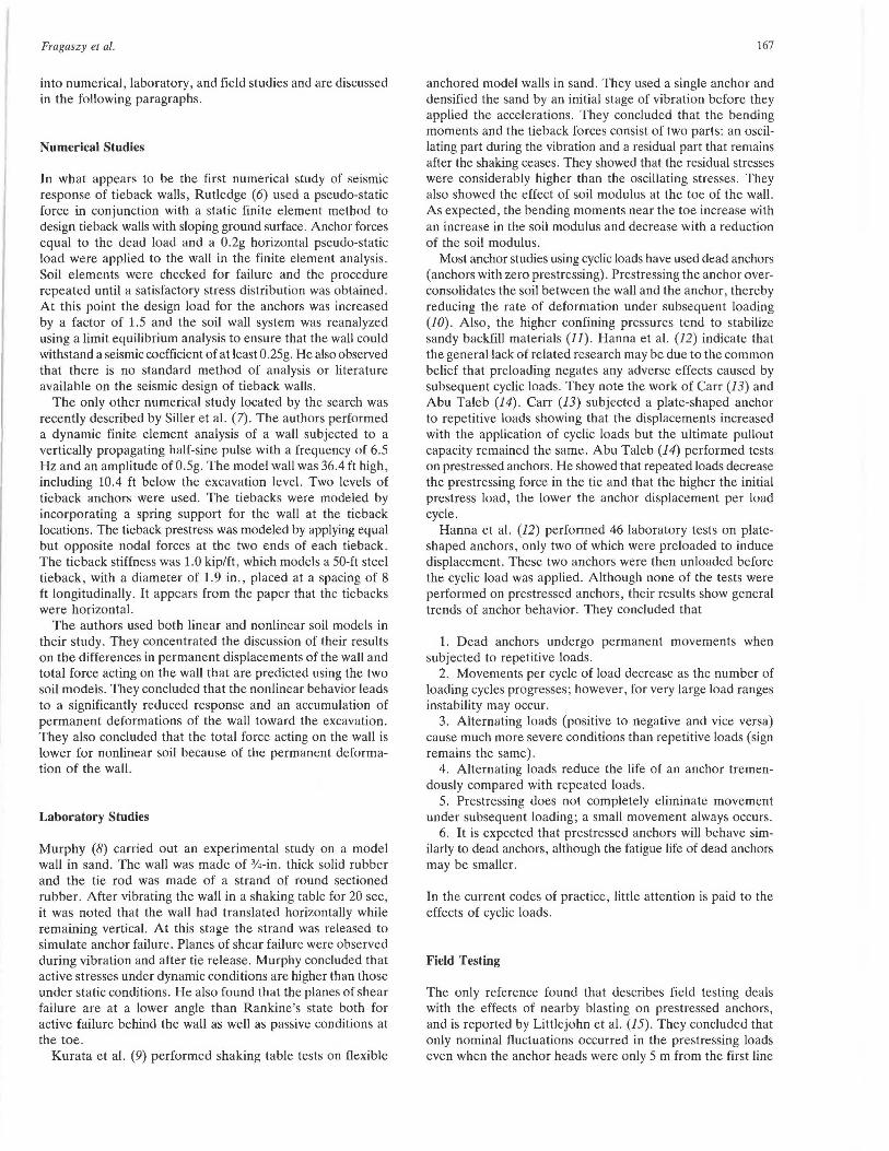
P ·,undaries on both the left and the right sides of the mesh a.,, fixed in the horizontal directions only, whereas, the bottom boundary is fixed against vertical movement as well . The finite element mesh used with SOIL-STRUCT is shown in Figure 2. It contains 238 elements and 270 node points.
The soil that is modeled in the analysis is a homogeneous silty sand. Its properties are listed in Table 1. Further details of the static input parameters are discussed by Ali (18).
Dynamic Analysis
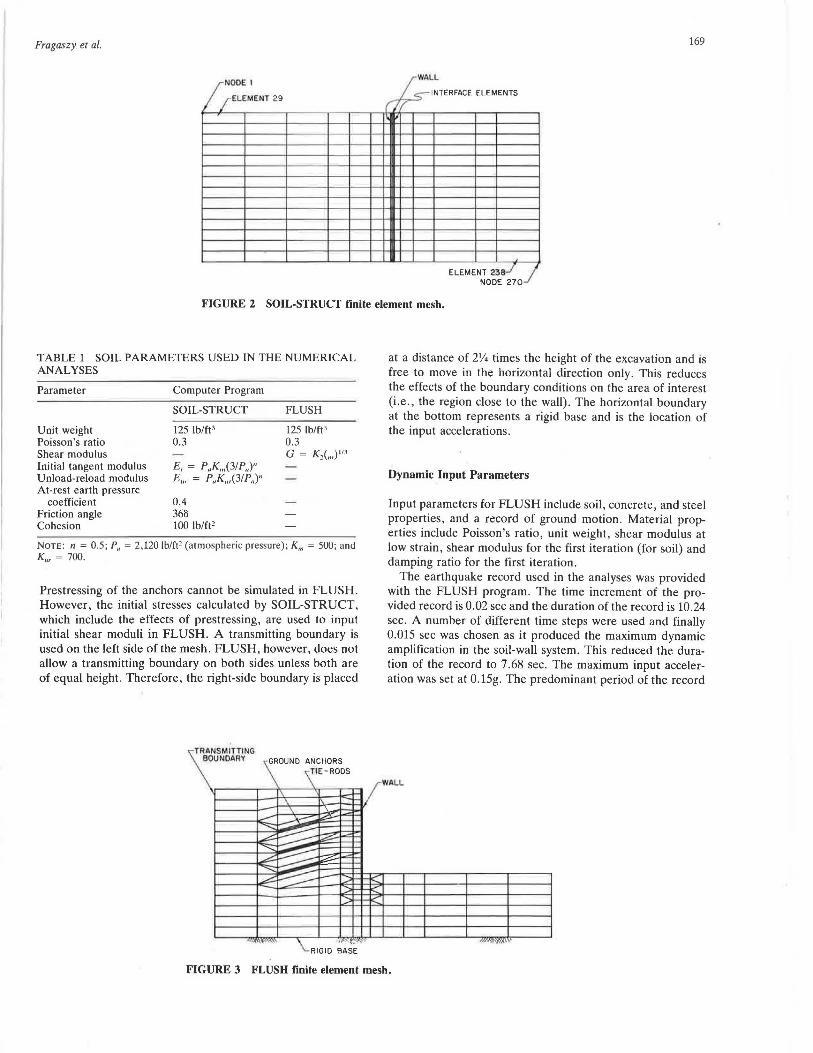
In order to incorporate the stresses obtained from the static analysis into the dynamic analysis, the dynamic finite element mesh was chosen to be as similar as possible to the mesh used in the static analysis . The mesh used for FLUSH, shown in Figure 3, contains 214 elements and 230 node points. Some of the major differences between the two meshes are:
• The ground anchors are modeled by springs in SOILSTRUCT and by continuum elements in FLUSH;
• Interface elements were not used in the dynamic analyses as they are not available in FLUSH; and
• The right boundary of the dynamic mesh is placed at a greater distance because of certain modeling constraints, as described later .
To determine the importance of interface elements, an analysis was made in which the elements bordering the wall were given negligible strength. Comparison with the analysis reported as follows indicates no significant differences.
Dynamic Model
In the FLUSH mesh , each ground anchor is modeled by two linear elastic solid elements with the properties of concrete . Ties connecting the wall to the ground anchors and the wall itself are both simulated by one-dimensional beam elements.
Fragaszy et al. 169
W L AL /;NOOE 1
INTERFACE ELEMENTS / ELEMENT 29 ,,-,
ELEMENT Z38J , ) NOOE 270
FIGURE 2 SOIL-STRUCT finite element mesh.
TABLE 1 SOIL PARAMETERS USED IN THE NUMERICAL ANALYSES
Parameter
Unit weight Poisson's ratio Shear modulus Initial tangent modulus Unload-reload modulus At-rest earth pressure
coefficient Friction angle Cohesion
Computer Program
SOIL-STRUCT
125 lb/ft' 0.3
E; = P,.K,..(31 P,.)" Eur = P.,Ku,(31 P,,)11
0.4 368 100 lb/ft2
FLUSH
125 lb/ft ' 0.3 G = K 2 (,..) "'
NOTE : n = 0.5; P,. = 2, 120 lb/ft' (atmospheri c pressure); K,.. = 500; and K,., = 700.
Prestressing of the anchors cannot be simulated in FLUSH. However, the initial stresses calculated by SOIL-STRUCT, which include the effects of prestressing, are used to input initial shear moduli in FLUSH. A transmitting boundary is used on the left side of the mesh. FLUSH, however, does not allow a transmitting boundary on both sides unless both are of equal height. Therefore, the right-side boundary is placed
TRANSMlnlNG BOUNDARY · GROUND ANCHORS
\ IE-RODS
I\ - '-'\ \ '\~ 1:21= .....
L---~ i::zs;...
-...;;::: ~ '"" -
.---:::. -...;: ~ ~ ~ ~ I:;;;: !=
""" ~ >--
.....-: - -:::~
I-
~~
~~'W'"'
\_ I 1"'-"'T:"'
ID BASE RG
at a distance of 21/4 times the height of the excavation and is
free to move in the horizontal direction only. This reduces the effects of the boundary conditions on the area of interest (i .e., the region close to the wall) . The horizontal boundary at the bottom represents a rigid base and is the location of the input accelerations.
Dynamic Input Parameters
Input parameters for FLUSH include soil, concrete, and steel properties, and a record of ground motion. Material properties include Poisson's ratio, unit weight, shear modulus at low strain , shear modulus for the first iteration (for soil) and damping ratio for the first iteration .
The earthquake record used in the analyses was provided with the FLUSH program. The time increment of the provided record is 0.02 sec and the duration of the record is 10.24 sec. A number of different time steps were used and finally 0.015 sec was chosen as it produced the maximum dynamic amplification in the soil-wall system. This reduced the duration of the record to 7.68 sec. The maximum input acceleration was set at 0.15g. The predominant period of the record
I / WALL
K' le'
~I<
m"''T'A
FIGURE 3 FLUSH finite element mesh.

170
.!!:! z Q 0.2
~ a: w _J w
TRANSPORTATION RESEARCH RECORD 1191
CONTROL MOTION
8 O H-~H+.o•ilf-•Tt-1-HI--~~~~~~~~~~~~~~~
<t
_J
~ ~-0. 2 N a: 0 :i::
2 3 4 5 6 7 e TIME (sec)
FIGURE 4 Input motion used in numerical analyses.
is 0.32 sec. A time history of the input motion used is shown in Figure 4.
RESULTS
Although the numerical studies conducted to date are preliminary in nature, they do shed considerable light on the problem. Of particular importance is the insight they give to the question of in-phase versus out-of-phase motion . One of the reasons often given for not considering seismic loading separately for tieback walls is the intuition that the wall and the soil backfill are in-phase. This means that the soil and the wall face tend to move together for the given hypothetical conditions and that there is little to no relative movement between them. It is often assumed that this will result in negligible increases in load on the wall. Although this study tends to confirm the in-phase behavior of the wall and the backfill , it clearly points out a second, perhaps more serious, consideration. On the basis of these numerical studies, it appears that the soil above and below the bottom of the excavation may not move in-phase. The analyses show that these two
layers of soil move in opposite directions during a significant portion of the shaking. This can be seen in Figure 5, which shows the horizontal acceleration of each node point 1.965 sec after the beginning of shaking. The vertical dashed lines represent zero horizontal acceleration. The soil lines represent the horizontal accelerations of the soil at that location in the mesh . Where the solid line is to the left of the corresponding dashed line, the soil is accelerating to the left; where the solid line is to the right of the dashed line, the soil is accelerating to the right. The magnitude of the acceleration is given by the distance between the solid and the dashed line. Although actual magnitudes of acceleration are difficult to pick out, it is clear from this figure that the upper and lower portions of the soil deposit are accelerating in opposite directions. This out-of-phase behavior leads to the development of high horizontal pressures and bending moments at the excavation level.
It was also found that relatively high vertical accelerations are induced in the wall and the soil, even though the input motion is entirely horizontal. This increases the bearing pressure at the base of the wall and lowers the safety factor against bearing capacity failure.
II o .33g
- 0 ~
r-~-r---<1.>-T-9--~-<r.9-~: i I
I w 10 (.)
<t u. a: ::J 20 en 0 z 30 ::J 0 a: ti> 40 :;;: 0 _J 50 w CD
:i:: 60 I-0.. w 0 70
I: I I I I I I
I 1 WALL
I 1 I I I I I
: I I
I I : I I
-i:G~ I I
RELATIVE HORIZONTAL ACCELERATION (g)
FIGURE 5 Horizontal acceleration at Time = 1.965 sec.

Fragaszy et al.
JOP or l.A'tfR' I
6
0.50.--~-.--,--.---.---.-,--,
f OP OF l AY£ff 1'4
-o. soo-~~Z--4~~~~~8
TIME (sec)
171
AT NQOAL POINT IZ6
-o.eoo'~~~2,--~~4~-s._..__.
TIME (sec)
FIGURE 6 Time histories of horizontal ground motion at four locations.
Finally, it was found that dynamic ·amplification of the base motion was produced, resulting in peak horizontal ground accelerations of 0.33g compared with a peak input acceleration of 0.15g.
The three factors discussed all influence the response of the wall-soil system. More detailed results are presented in the following paragraphs for each of the major parameters of wall behavior: displacements, horizontal accelerations, pressures on the wall, bending moments, vertical accelerations and tie forces.
Wall Displacements
The FLUSH program does not calculate absolute displacements of the system, but rather pseudo-displacements. However, based on these data it is clear that some residual displacement does occur because of shaking. Additional studies will have to be conducted to determine the potential magnitude of these displacements .
Horizontal Acceleration
Maximum horizontal accelerations in the wall occur at the top, where they are slightly more than twice the maximum input motion. The wall acceleration decreases with depth and at the bottom of the wall it is only slightly higher than the peak input acceleration. Amplification of horizontal accelerations in the free field is lower than that observed both in the soil near the wall and in the wall itself. This is illustrated in Figure 6, which shows time histories of horizontal acceleration at various locations.
Soil Pressures on the Wall
Large dynamic horizontal pressures are induced on the wall near the bottom of the excavation. This can be seen in Figure 7, which shows the static pressure and the maximum dynamic pressure on the wall versus the depth below the ground surface . Below the excavation level the net soil pressure on the
o~-------~-------~~------~-. -.... w u Lt 10 MONONOBE-OKABE PRESSURE 0::: ::J en 0 02 z ::J 0 0::: (!) 30 ~ g w m 40 ::i::: l-a.. w 0 502000
FIGURE 7
1000 0
NET HORIZONTAL EARTH PRESSURE (lb/sq ft)
Earth pressures acting on wall.
1000

172 TRANSPORTATION RESEARCH RECORD 1191
~ o.------,,..c-.-=::----.-----..-------,-----, -- -~ - -- -... ---~ 10 TIE ROD - -- -:;.-
::> (f)
0 z 20 ::> 0 a: l!)
~ 3D 0 _J w
TIE-ROD
TIE -ROD
CD 40 1--.,....,.<vm--I la._ w
;
~ ... ,,.
~;STATIC ~
------~ DYNAMIC
0 50 '----------::;_ ___ ..__ ___ _. ___ _ _,_ ___ __.
0 1500 3000 4500 6000
BENDING MOMENT ft-lb
FIGURE 8 Static and peak dynamic moments in wall.
wall is p.lotted. The upper 30 ft of wall are subjected to only negligible dynamic pressures, but beginning at the level of the lower ieback the pres ·ure increase dramatically to a peak of approximately 600 lb/in .2 2 ft above the excavation . This dynamic increment is approximately 40 percent of the static pressure at this locati n . The reason for this larg increase in pressure is the out-of-phase motion of the upper soil ver us the lower soil.
T he dynamic earth pre ure predicated using the Mononobe-Okabe equa1ions are als pl tted on Figure 7. A wall friction angle of 18 degrees and a ho rizontal ground acceleration of 0.15g were used to obtain this pres ure diagram. [n this case, the Monon be-Okabe meU10d overpredict the dynamic ea rth pressure by a significant amount except for a small 2-ft interval near the excavation level.
Bending Moments
The movement of the wall and the large dynamic pressures g nerated by the out-of-phase behavior of the soil above and below the excavation level led to large dynamic bending moments in the wall , as illu trated in Figure 8. In this figure ,
_J
"" u
"''l f:= a:: w >
-04 0 2 3
the dynamic bending moment 1.965 sec after the beginning of shaking is plotted versus location along the waU. These moments are largest at the excavation level, where it is approximately - 4,500 lb-ft/ft. This dynamic moment is approximately 10 percent of the static moments at this location and, therefore represents a reduction in safety factor. Similar dynamic momenr · are produced at other times during the shaking.
Vertical Accelerations
Very large vertical accel ration. , approximately equal to the maximum horizontal inpui motion , are induced in the region between the wall and the anchors. This is illu trated in Figure 9, which how. the time history of vertical acceleration at Node Point 101, located at the ground surface behind the wall. Sitar and Clough (19) also noted high vertical accelerations when analyzing the seismic response of steep slopes in cemented sands. It is believed that these accelerations are real and not caused by difficulties in the numerical procedures. Rocking of the soil-wall system is the most likely cause of the vertical accelerat ions.
AT NODAL POINT IOI
i 4 5 6 7 8
TIME (sec)
FIGURE 9 Time history of vertical acceleration at Node IOI.

Fragaszy et al.
0.4~-~-~-~-~-~-~-~~
z 0
0.2
t== -02 <l'. . 0:: w
TOP OF THE WALL
d -0.4 ,___..___..___..___..___..___..___..____,
8 0.4 <l'.
....J <l'. 0.2 u lo::
BASE OF THE WALL
W O"t~H11"ffirtHH'1.,......,.._..,._~--------t >
-0.2
2 4 TIME (sec)
6
FIGURE IO Time histories of vertical acceleration at top and bottom of wall.
-;: 0 ~ w u ~ 10 TIE-ROD a: ::::> en 0 z 20 TIE-ROD ::::> 0 a: (.!)
3:: 30 TIE-ROD 0 ....J
8
w ~XCAVATION LEVEL ID
J: 40 ~?f!
I-Q_ w 0 50
0 DYNAMIC AXIAL
5000
173
The wall itself also undergoes significant vertical accelerations, as shown in Figure 10. These accelerations cause large axial stresses to develop in the wall that are transmitted to the ground. This is shown in Figures 11 and 12. Figure 11 is a plot of maximum dynamic axial force in the wall as a function of depth. The peak dynamic vertical stress in the ground immediately below the wall can be seen in Figure 12.
It is possible that the lack of an interface element between the wall and the soil might affect the predicted values of vertical pressures beneath the wall. To estimate the possible effects of slippage between the wall and the soil, an analysis was conducted in which the stiffness of the soil immediately adjacent to the wall was reduced to a negligible value. The results indicate minimal effect, thus indicating that the lack of an interface element does not appear to be a problem.
Tie Forces
In these analyses negligible dynamic load increments are induced in the tie rods. The peak dynamic loads are -428 lb, -434 lb, and 413 lb for the upper, middle, and lower tie rods, respectively. In comparison, the prestressing force applied
10,000 15,000 FORCE I UNIT WIDTH (lb/ft)
FIGURE 11 Peak dynamic axial force in wall.
VERTICAL STRESS ( PSF)
- 0$600
~- - • 1200 ~
-:::;;;;. ml 1600 ....-'.'.:: ~ ~ --
"" ~ ~-.2300
......-::: ~
~-......-:: :::i - -<
"'",~" 111111 Ill
111111 Ill
"'• ·'Y'°" •• -,,,.~,.f.\l
FIGURE 12 Peak dynamic vertical stresses beneath wall.

174
during construction is 11,000 lb. It should be remembered, however, that all three levels of tie rods are located in the upper layer of soil above the base of the excavation. There is little relative movement between the wall and the soil in this layer. It is probable that significant tie forces would develop in the tie rods in situations in which the anchors are located in the lower soil layer. An even more important consideration in this case is the possibility of load reversals occurring if the anchor is moving out-of-phase with the wall. As discussed by Hanna, significant loss of anchor strength may develop in such a case.
DISCUSSION
It is important to realize the limitations of the numerical study described above. Because the objective was to do pilot work to determine whether a more detailed numerical study was justified, only one wall and soil profile were considered. It is with care, therefore, that general conclusions should be made regarding other wall geometries , input motion, and soil profiles. This study does show that for at least one set of conditions significant dynamic loading can occur.
It is likely that there are less favorable combinations of wall geometry, soil profile, and input motion so the results of this study cannot be taken as an upper bound. An example of a case in which the loads on the wall might be much more severe would be a wall that penetrated through a soft layer into a very stiff one. Considerably lower forces might be generated when the soil deposit was relatively uniform and the wall height was small compared with the depth of the deposit.
Another limitation of this study comes from the selection of a single soil profile. It appears that the major factor in the response of the wall to seismic loading is the out-of-phase behavior of the upper and lower soil layers. The location of the anchors relative to the bottom of the excavation may also be important. In an extreme case , an anchor embedded in a very stiff layer below the excavation might be subjected to load reversals when the upper soil is much softer. As described in the literature review, load reversals significantly affect the capacity of anchors and could lead to failure of the anchor much more quickly than repeated loading without load reversal.
Finally, it should be made clear that the program FLUSH has many limitations that must be recognized when evaluating the results of this study. The inability to include static stresses, lack of an interface element, and inability to provide information on permanent displacements limits its usefulness . However, this study does point out potential problems that should be examined in detail by more sophisticated methods. The authors are continuing this work using a time domain, nonlinear program, FLEX, which is believed to be better suited for the analysis of this type of problem.
SUMMARY AND CONCLUSIONS
The results of a literature review and a pilot numerical study of the seismic response of tieback walls are presented in this paper. The literature review clearly shows that very little research has been conducted on this subject and that there is no recognized analysis-design procedure for seismic loading
TRANSPORT A TfON RESEARCH RECORD II9/
of tieback walls. The results of the pilot finite element analysis point out at least two possible difficulties associated with dynamic loading. The first is out-of-phase motion of the soil above and below the excavation level. This can cause high dynamic soil pressures on the wall near the excavation level and high dynamic bending moments in the wall. This may also lead to load reversals on anchors located below the excavation level. The second is rocking of the wall-soil system leading to high bearing pressures in the soil below the wall.
Based on this pilot work the conclusion is reached that there are potential problems related to seismic loading of tieback walls and more extensive numerical analyses are required to determine the extent of these problems. The authors are currently engaged in a follow-up numerical study in which a more complete parametric analysis is being conducted . Included in the parameters to be studied in more detail are ground slope, soil properties, anchor location, earthquake record and wallbackfill geometry.
ACKNOWLEDGMENTS
The research described in this paper was supported by the Washington State Department of Transportation and the Federal Highway Administration.
REFERENCES
1. R. S. Cheney. Ground Anchors. Federal Highway Administration Report FHWA-DP-68-1 , U.S. Department of Transportation, 1984.
2. T. H. Hanna. Foundations in Tension: Ground Anchors. McGrawHill Book Co., New York, 1982.
3. P. J. Nicholson, D .D. Uranowski, and P. T. Wycliffe-Jones. Permanent Ground Anchors: Nicholson Design Criteria. Federal Highway Administration Report FHWA/RD-81/151 , U.S. Department of Transportation, 1985.
4. H. Schnabel, Jr. Tiebacks in Foundation Engineering and Construction. McGraw-Hill Book Co., New York , 1982.
5. D. E. Weatherby. Tiebacks. Federal Highway Administration Report FHWA/RD-82/047, U.S. Department of Transportation, 1982.
6. J. C. Rutledge. Tie-Back Retaining Walls. New Zealand Engineering, Vol. 30, No. 8, Aug. 1975, pp. 242-247.
7. T. J . Siller, P. P. Christiano, and J. Bielak. Structures and Stochastic Methods (A.S. Cakmak, ed.). Developments in Geotechnical Engineering. Vol. 45, Elsevier Publishing Co., Amsterdam, The Netherlands, 1987, pp . 141-150.
8. V. A. Murphy. The Effect of Ground Characteristics on the Aseismic Design of Structures . In Proc. , Second World Conference on Earthquake Engineering, Tokyo, Japan, Vol. 1, 1960, pp. 231-248.
9. S. Kurata, H . Arai, and T. Yokoi. On the Earthquake Resistance of Anchored Sheet-Pile Bulkheads. In Proc., Third World Conference on Earthquake Engineering, Vol. 2, 1965, pp. 369-383.
10. D. H. Trollope, I. K. Lee, and J. Morris. Stresses and Defor m'.:lltlnn in 'T'n1n_T -:l\/Pr P•:n1P. m i:> nt ~t-r111"'t11re>eo T Tnrlo.- ~I,..,., DL>o~"" " • ""rl ------- -- --- - • - --J -- - - • -- - ---- - ~-- ----- -~ _, - · --· .............. ............ t'_. ............ .....
Loading. ln Proc., First Conference Australia Research Board, Vol. 1, Part 2, 1962, pp . 693-720.
11. J. R. Morgan. The Response of Granular Materials to Repeated Loading. In Proc., Third Conference Australia Research Board, Vol. 3, Part 2, 1966, pp. 1178-1193.
12. T. H. Hanna, E. Sivapalan , and A. Senturk. The Behavior of Dead Anchors Subjected to Repeated and Alternating Loads. Ground Engineering, Vol. 11, No. 3, 1978, pp. 28-34.
13. R. W. Carr. An Experimental Investigation of Plate Anchors in Sands. Thesis, Sheffield University, England, 1971.

Fragaszy et al.
14. G . M. A. Abu Taleb. The Behavior of Anchors in Sand . Thesis, Sheffield University, England, 11974.
15. G . S. Littlejohn, P. J. Norton, and M. J . Turner. A Study of Slope Reinforcement at Westfield Open Pit and the Effect of Blasting on Prestressed Anchors. In Proc., Conference on Rock Engineering, University of Newcastle upon Tyne, England, April 1977.
16. J. Lysmer, T. Udaka, C. F. Tsai, and H. B. Seed. FLUSH-A Computer Program for Approximate 3-D Analysis of Soil-Structure Interaction Problems. Report No. 75-30, Earthquake Engineering Research Center, University of California, Berkeley, Calif., 1975 .
17. G. W. Clough and Y. Tsui. User's Guide, ProgramSOIL-STRUCT. Duke University, Durham, North Carolina, 1973.
175
18. A. Ali. Seismic Response of Tieback Retaining Walls . M.S. thesis, Washington State University, 1986.
19. N. Sitar and G. W. Clough. Seismic Response of Steep Slopes in Cemented Soils. Journal of Geotechnical Engineering, ASCE, Vol. 109, No. 2, 1983, pp. 210-227 .
The contents of this paper reflect the views of the authors and do not necessarily reflect the official views or policies of WSDOT or FHWA.
Publication of this paper sponsored by Committee on Subsurface Soi/Structure Interaction.