seismic safety of chancy-pougny dam - · pdf fileit allows the circulation of a titan gantry...
TRANSCRIPT
1 INTRODUCTION
1.1 Context
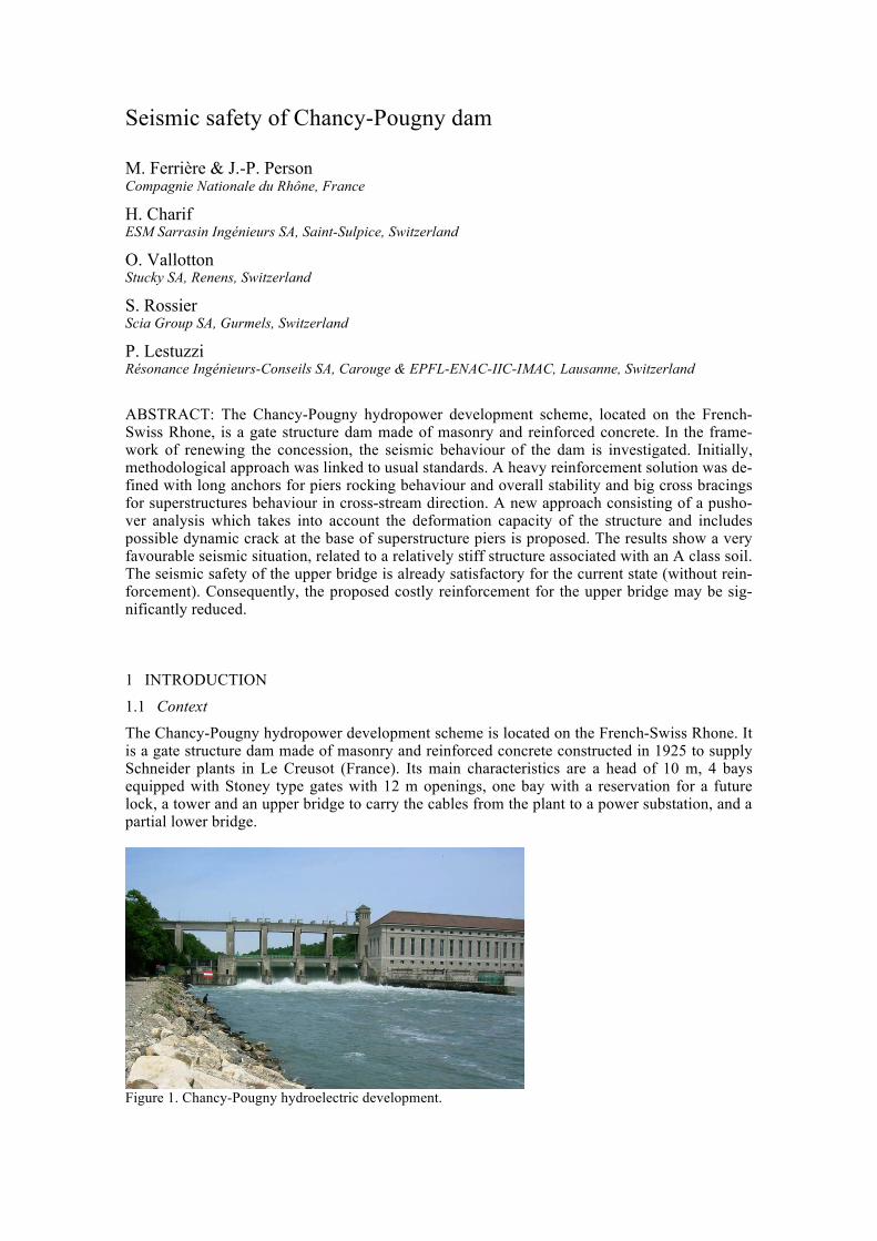
The Chancy-Pougny hydropower development scheme is located on the French-Swiss Rhone. It is a gate structure dam made of masonry and reinforced concrete constructed in 1925 to supply Schneider plants in Le Creusot (France). Its main characteristics are a head of 10 m, 4 bays equipped with Stoney type gates with 12 m openings, one bay with a reservation for a future lock, a tower and an upper bridge to carry the cables from the plant to a power substation, and a partial lower bridge.
Figure 1. Chancy-Pougny hydroelectric development.
Seismic safety of Chancy-Pougny dam
M. Ferrière & J.-P. Person Compagnie Nationale du Rhône, France
H. Charif ESM Sarrasin Ingénieurs SA, Saint-Sulpice, Switzerland
O. Vallotton Stucky SA, Renens, Switzerland
S. Rossier Scia Group SA, Gurmels, Switzerland
P. Lestuzzi Résonance Ingénieurs-Conseils SA, Carouge & EPFL-ENAC-IIC-IMAC, Lausanne, Switzerland
ABSTRACT: The Chancy-Pougny hydropower development scheme, located on the French-Swiss Rhone, is a gate structure dam made of masonry and reinforced concrete. In the frame-work of renewing the concession, the seismic behaviour of the dam is investigated. Initially, methodological approach was linked to usual standards. A heavy reinforcement solution was de-fined with long anchors for piers rocking behaviour and overall stability and big cross bracings for superstructures behaviour in cross-stream direction. A new approach consisting of a pusho-ver analysis which takes into account the deformation capacity of the structure and includes possible dynamic crack at the base of superstructure piers is proposed. The results show a very favourable seismic situation, related to a relatively stiff structure associated with an A class soil. The seismic safety of the upper bridge is already satisfactory for the current state (without rein-forcement). Consequently, the proposed costly reinforcement for the upper bridge may be sig-nificantly reduced.

In the framework of renewing the concession, the French-Swiss supervisory authorities, i.e. direction régionale de l’environnement, de l’aménagement et du logement (DREAL) and Swiss federal office of energy (OFEN), requested the owner of the structure, the Société des Forces Motrices de Chancy – Pougny (SFMCP), to carry out a study on the dynamic behavior of the dam under seismic loads.
The assessment of the dam's dynamic behavior was performed in conformity with the direc-tives of the two supervisory bodies. Given the characteristics of the development scheme, an earthquake loading with a return period of 5000 years was taken into account.
The entire structure was modelled with three dimensional finite elements, taking into account dynamic soil-structure interaction (mixed rock-alluvial soil foundations) and the structure–mass of entrained water interaction. Model resolution consisted of linear dynamic analysis using the acceleration response spectra method completed with a pseudo-static analysis that cumulated load cases. Verifying the internal resistance of the structure demanded knowledge of existing conditions, especially the mechanical characteristics of the concretes used. The integrity of the gates was studied by using a specific finite elements model.
After revealing structural deficiencies, choosing the solution of reinforcement entailed a compromise between several criteria including severe operating constraints, safety considera-tions during works, architectural constraints, technical feasibility, cost and lead-time objectives.
This leads to a major and costly project. Consequently, an alternative approach is proposed to the supervisory authorities that takes into account a displacement-based analysis that allows for ductile behaviour of concrete structures. The paper focuses on the description of this alternative approach and on the related results.
Figure 2. Cross-section of the Chancy-Pougny dam.
1.2 Dam Description
The Chancy-Pougny development scheme straddles the French-Swiss frontier. It is equipped on the Swiss left bank with an electrical power plant with 5 Francis turbine units of 7.7 MW each. The initial design flow is 520 m3/s. The refurbishment project includes the complete replace-

ment of the 5 existing Francis turbine units by Kaplan turbine units of 12 MW each, turbining 140m3/s under a mean head of 10m. This project is associated with compensatory measures, namely a fish pass on the right bank. The electric substation is located on the French right bank with a 123 kV power line to Swiss.
Each gate is composed of a 60 t lower part and a 15 t upper part, operated by chains from the upper bridge. A lock for navigations is provided for a reservation in the additional bay.
Five concrete piles support the equipments: they are composed of a lower part (pillars) 21.7 m high made of reinforced concrete with stone facing and an upper part (piers) 12.4 m high made of lightly reinforced concrete with cement coating. The piles are founded on caissons sunk into a molasse substratum. An intermediate 4 m thick foundation slab guarantees the dam against hydraulic erosion between piles.
A 26 m high cable tower is used to route the electrical power cables from the plant to the sub-station: a gallery in the upper bridge completes this routing between the two banks, more pre-cisely between the cable tower and the right abutment. This bridge is made of isostatic beams simply supported at the top of the piers. It allows the circulation of a Titan gantry crane with a 600 kN dead weight used for bulkhead gate installation.
2 INITIAL SEISMIC ANALYSIS
2.1 Seismic parameters
The assessment of the dam's dynamic behavior was performed in conformity with the OFEN di-rectives. Given the characteristics of the development scheme, the dam was classified as class II. An earthquake loading with a return period of 5000 years was taken into account.
The methodology was taken from the OFEN chapter relating to barrages. The OFEN 5000 years spectrum was adopted as a checking signal. For a 5% damping ratio and class soil A, the response spectrum is characterized by a peak ground acceleration of 0.23 g and a maximum plateau acceleration of 0.58 g horizontally.
Figure 3. OFEN spectrum with a return period of 5000 years – A class soil – Damping ratio 5%.
2.2 Linear dynamic analysis
The first approach consisted of a linear dynamic analysis using the response spectrum method. The OFEN response spectrum was applied in the two main horizontal directions and in the ver-tical direction with an attenuation factor.
Scia Engineer software was used to model the entire structure with three dimensional finite elements: beam elements for piers, cable tower, upper and lower bridges; shell elements for piles; thick plates for foundation slabs. Particular attention was given to the dynamic soil struc-ture interaction of the abutment foundation: a system of springs and masses was modelled to take into account phase shifts and amplification between the bedrock and the top of alluvial col-umn.

Figure 4. Chancy-Pougny dam - 3D finite elements model.
The results showed that the main deficiencies appear in the cross-stream direction which is
not mobilized under service conditions. Excess tensile stresses (up to 10 MPa) were determined in the cable tower and upper part of the piles due to cross-stream excitation. For the lower part of the piles, conventional tensile resistance was also exceeded due to entrained water in the along-stream direction. Regarding global stability, given the fact that passive earth pressure was minimized in the superficial molasse, thus stability against sliding and overturning was not guaranteed.
2.3 Initial proposed reinforcement
The choice of the initial proposed reinforcement solution was a compromise between: - Severe operating constraints: e.g. no simultaneous blocking of two gates during works, - Safe working conditions, e.g. the proximity of HV cables inside upper bridge, - Architectural constraints: the plant is listed as a historic monument, - Expected low quality concrete in the pillars identified by local investigation, - The technical feasibility of long anchors to ensure the overall stability of the structure.
The principles adopted were: - St Andrew steel cross braces to resist cross-stream excitation (Fig. 5), - Abutment on the right bank slope: ground anchors to stabilize in the cross-stream direction, - Piles: vertical anchors 38 m in length to counteract along-stream overturning of piles, - Piles: inclined anchors 38 m in length to counteract sliding of piles, - Cable tower: vertical anchors 40 m in length and thickening of the concrete at its base.
Figure 5. Chancy-Pougny dam –Seismic initial proposed reinforcement project.
The initially adopted methodology leads to a major reinforcement project that is also complex in terms of feasibility, particularly for long drilled tensioned anchors in old concrete structures. As a consequence, an alternative is proposed to the supervisory authorities. This alternative ap-proach is based on a “push-over” analysis of the upper part of dam. This method may not be ap-plied to the lower part of the dam because of its role in hydraulic retention.
3 DISPLACEMENT-BASED APPROACH
3.1 Methodology
The structural characteristics of the upper part of the dam are similar to the ones of conventional bridges. Therefore it was proposed to apply modern seismic assessment methodologies, now usually involved in case of existing structures, to the upper bridge. These modern methodolo-gies are displacement-based approaches. Compared to conventional forced-based approaches, they consider the seismic behavior more realistically. More specifically, they allow taking into account the actual “plastic” displacement capacity after reaching the strength of the structure.
In the case of Chancy-Pougny dam, the displacement-based approach allows to consider the rocking behavior of the 12.4 m high piers of the upper bridge. This means that, compared to the initial approach, the condition of avoiding cracking at the base of the piers is no more consid-ered. By contrast, cracking at the base is used since it leads to a seismic satisfactory rocking be-havior, generally associated with relatively large displacement capacity. Furthermore, prelimi-nary investigations, considering only one pier, with the related portion of the upper bridge, showed that this displacement-based approach is very favorable for the upper part of the dam because of its relatively high stiffness, leading to small displacement demand.
3.2 Displacement-based method
The used methodology was developed for seismic assessment and design of buildings and bridges (Priestley et al. 2007). This is a nonlinear – static method, oriented in deformation, which generally leads to more favorable results than conventional force-based methods. This method applies to deformable structures, i.e. to structures which behavior is not governed by fragile collapse. This method should not be confused with the capacity design method which is more restricting and only concerns new structures.
Generally in the displacement-based method, a capacity curve is first determined for each el-ement of the lateral stabilization (shear wall, frame, etc.). The capacity curve is defined by three points: the lateral strength of the element, the yield displacement, and the ultimate displacement. The global capacity curve for the structure is obtained by the addition of the individual elements capacity curves. The strength and the displacement capacity (ultimate displacement) of the structure are determined by the global capacity curve. The seismic safety is then evaluated by the comparison of structural displacement capacity with the displacement demand associated with the related response spectrum. This comparison is generally graphically illustrated with a diagram called ADRS spectrum.
3.3 Assumptions
The capacity curves of the piers were determined based on the three following parameters: the top displacement when uplift appears at the base, the lateral strength corresponding to a rocking failure mode and the ultimate drift. The rigidity is the ratio of the uplift displacement to the as-sociated lateral strength. Lateral strength by rocking constitutes the plateau of the capacity curve.
Based on the values of deformation capacity for masonry shear walls proposed by Eurocode 8 (EC 8, 2005), i.e. 0.4 % in case of shear failure and 0.8 % for rocking failure, a value of 0.8 % was considered as ultimate drift. The very low reinforcement (near no reinforcement) at the base of the piers leads to a rocking behavior characterized by a bending strength only due to the nor-mal compression force at the base. Moreover, shear failure mode may be excluded because of the high slenderness (height/length ratio) of the piers and the fact that they are made of rein-forced concrete. Note that the adopted value for ultimate drift may be considered as very careful

because EC 8 allows for the masonry shear walls governed by a rocking failure mode to in-crease the basic value of 0.8 % through its multiplication by the corresponding slenderness ratio.
3.4 Results
Figure 6 shows the capacity curve of the upper bridge in the cross-stream direction for the cur-rent state (without reinforcement). In this direction, the upper bridge is analyzed globally be-cause the connection by the gallery leads to an identical top displacement for all elements. The individual curves for each element (tower and piers I to V) are first determined. The global ca-pacity curve is obtained by adding up all individual curves.
Figure 6. Capacity curve of the upper bridge for the cross-stream direction
In the cross-stream direction, lateral strength of the upper bridge is about 6400 kN. The yield
displacement at the top is approximately 6 mm. The fundamental period is about 0.4 s. Accord-ing to the assumption of a value for ultimate drift of 0.8 %, the top displacement capacity is ap-proximately 110 mm.
In the stream direction, the piers may be analyzed independently because, in this direction, the connection by the gallery does not lead to an identical top displacement for the elements. The piers resist in their larger cross-section dimension. Therefore, the fundamental periods are much smaller than the one in the cross-stream direction and do not exceed 0.2 s.
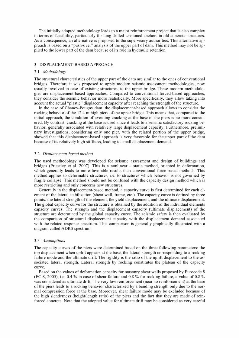
Figure 7 shows the seismic evaluation of the upper bridge for the cross-stream direction in the usual ADRS format. According to the EC 8 procedure, the fundamental period just enter the validity domain of the equal displacement rule. As a consequence, displacement demand does not depend on the strength of the structure. For the fundamental period of the upper bridge, the top displacement demand is about 23 mm, which is much smaller than the top displacement ca-pacity of 110 mm.
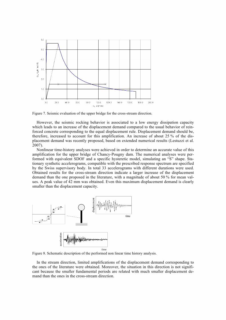
Figure 7. Seismic evaluation of the upper bridge for the cross-stream direction.
However, the seismic rocking behavior is associated to a low energy dissipation capacity
which leads to an increase of the displacement demand compared to the usual behavior of rein-forced concrete corresponding to the equal displacement rule. Displacement demand should be, therefore, increased to account for this amplification. An increase of about 25 % of the dis-placement demand was recently proposed, based on extended numerical results (Lestuzzi et al. 2007).
Nonlinear time-history analyses were achieved in order to determine an accurate value of this amplification for the upper bridge of Chancy-Pougny dam. The numerical analyses were per-formed with equivalent SDOF and a specific hysteretic model, simulating an “S” shape. Sta-tionary synthetic accelerograms, compatible with the prescribed response spectrum are specified by the Swiss supervisory body. In total 33 accelerograms with different durations were used. Obtained results for the cross-stream direction indicate a larger increase of the displacement demand than the one proposed in the literature, with a magnitude of about 50 % for mean val-ues. A peak value of 42 mm was obtained. Even this maximum displacement demand is clearly smaller than the displacement capacity.
Figure 8. Schematic description of the performed non linear time history analysis.
In the stream direction, limited amplifications of the displacement demand corresponding to
the ones of the literature were obtained. Moreover, the situation in this direction is not signifi-cant because the smaller fundamental periods are related with much smaller displacement de-mand than the ones in the cross-stream direction.

4 CONCLUSIONS
Displacement-based approach for the superstructure piers of the Chancy-Pougny allows point-ing out a very favorable seismic situation. This situation is related to a relatively stiff structure associated with an A class soil. The results show that the seismic safety of the upper bridge is already satisfactory for the current state (without reinforcement). Consequently, the proposed costly reinforcement for the upper bridge may be significantly reduced.
5 REFERENCES
Priestley M.J.N., Calvi G.M. and Kowalsky M.J. 2007. "Displacement-Based Seismic Design of Struc-tures". IUSS Press, Pavia, Italy.
Eurocode 8. 2004. "Design of structures for earthquake resistance - Part 1 : General rules, seismic actions and rules for buildings ", Comité Européen de Normalisation, Bruxelles.
Eurocode 8. 2005. " Design of structures for earthquake resistance - Part 3 : Assessment and retrofitting of buildings", Comité Européen de Normalisation, Bruxelles.
Lestuzzi P., Belmouden Y., Trueb M. 2007. "Non-linear seismic behavior of structures with limited hys-teretic energy dissipation capacity". Bulletin of Earthquake Engineering. Vol 5/4, 2007, pp. 549-569.