seismic testing of suspended plasterboard systems
DESCRIPTION
A testing method developed for seismic analysis of suspended plasterboard systems as a part of a Industry Defined Problem given by Saint Gobain in CEA Fest 2014 at IIT MadrasTRANSCRIPT

Industry Defined Problem
Team ChingariNeelotpal Shukla
Nijansh Verma

CONTINUOUS PLASTERBOARD
CEILING SYSTEMS
Introduction to systems and systems commonly used

Plasterboard is basically an inner layer of gypsum sandwiched between two outer layers of lining paper including various additives in the gypsum layer.
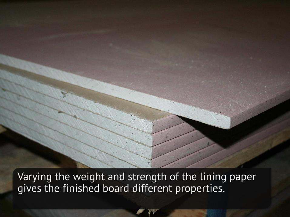
Varying the weight and strength of the lining paper gives the finished board different properties.

Suspended Ceiling Secondary ceiling, hung below the main (structural) ceiling. A staple of modern construction and architecture.

Suspended Ceiling Suspended ceilings provide excellent aesthetics and have been used for a long time for hiding the building infrastructure.
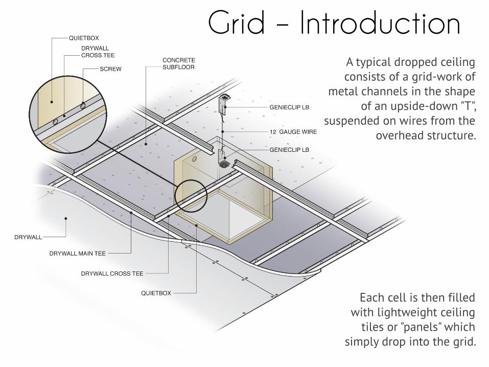
Grid – Introduction A typical dropped ceiling consists of a grid-work of
metal channels in the shape of an upside-down "T",
suspended on wires from the overhead structure.
Each cell is then filled with lightweight ceiling
tiles or "panels" which simply drop into the grid.
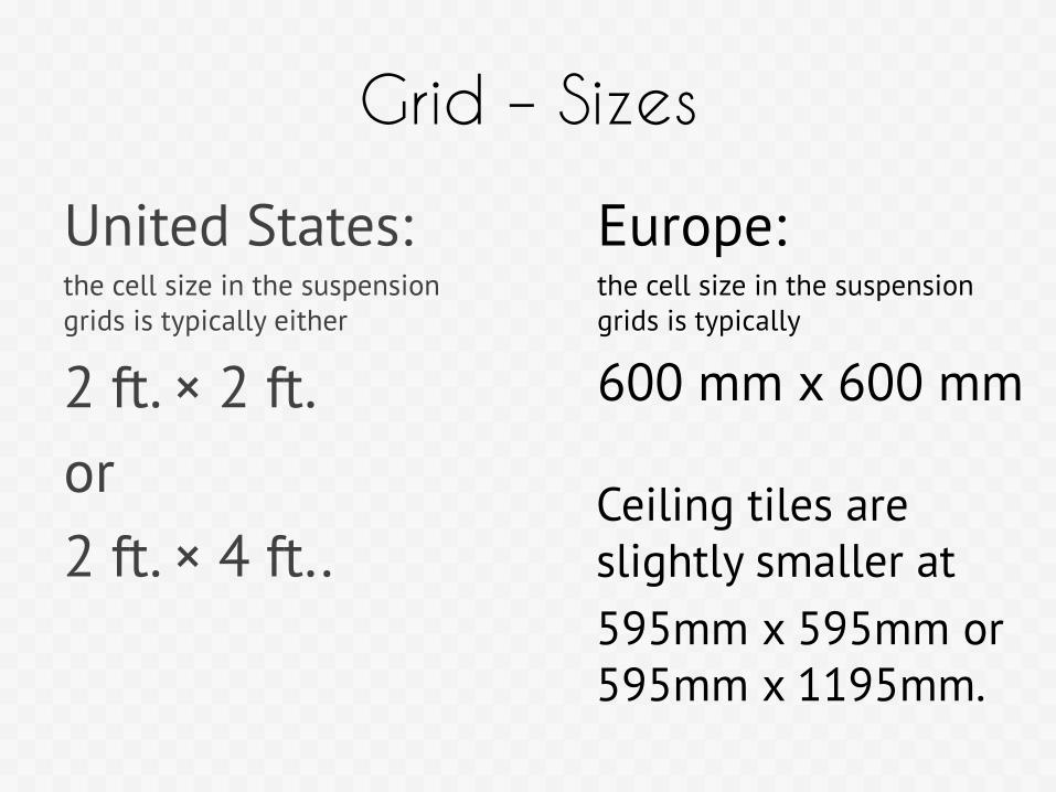
Grid – Sizes
United States: the cell size in the suspension grids is typically either
2 ft. × 2 ft.
or
2 ft. × 4 ft..
Europe: the cell size in the suspension grids is typically
600 mm x 600 mm
Ceiling tiles are slightly smaller at
595mm x 595mm or 595mm x 1195mm.

Tile Types
Fire RatedFire-Rated systems
consist of an aerated
gypsum core with glass
fibres, water repellent
and other additives
encased in.
AcousticThe sheets made for
acoustic performance
enhancement are
composed of a high-
density gypsum core
encased in a heavy-
duty linerboard.
NormalProvide only minimum fire safety as required by standards.
Do not enhance acoustic performance of the space.
A large variety of surface finishes and thicknesses is available.

Market Products
• CSR Gyprock: CSR Gyprock has developed a wide range of decorative ceiling systems as well as a large selection of fire and/or acoustic rated ceiling systems to meet specific FRL Rw
and Sound Absorption requirements.
• BORAL: Boral offers products in 3 different categories; Fire-Rated Ceiling Systems, Non Fire-Rated Ceiling Systems and QuietZoneTM
Ceiling Systems.

Market Products
• Saint Gobain Gyproc: SG Gyprock offers the most variety in terms of available products;
– Gypsum Plasterboard False Ceiling System
– Ecophon Ceiling Tiles System: These acoustic ceiling tiles offer a noise reduction coefficient (NRC) rating ranging from 0.90 to 1.00
– Gyptone Ceiling: Gyptone ceilings provide an outstanding sound absorption ranging from 0.8 to 0.85 and eye-catching aesthetics

PLASTERBOARD CEILING SYSTEMS –INSTALLATION
Installation methods and sample quantity specification

Grid System Types – 1
Flush Jointed Ceiling Systems
Flush Jointed Ceiling Systems utilise standard plasterboard sheet which is fixed to appropriately prepared framing. Plasterboard joints are ‘taped and set’ to form a smooth ‘flush jointed’ continuous ceiling suitable for painting.


Grid System Types – 2
Panel Ceiling Systems: These panels are generally placed in a two-way grid which is suspended below floor or roof framing. The pre-coated face of the supporting grid or edge profile of the panels combine with various surface textures to form a decorative feature ceiling.

Fixing Method Type – 1
Direct fixing: plasterboard may be fixed directly to steel furring which is held by appropriate direct fixing clips attached to a structural support.


Fixing Method Type – 2
Resilient Mounts: Resilient Mount may be screw fixed directly to the underside of joists or trusses using screws.


Fixing Method Type – 3
Concealed Grid Suspended Ceiling: plasterboard may be fixed directly to steel furring which is part of a concealed grid suspended ceiling frame.

Fixing Method Type – 3
Extensive attention to detailing is paid because a large variety of suspension mechanisms are available and new ones can be devised by assembling the various components together.


Quantity SpecificationsComponent Quantity Required
1 Advantage E 2.8/m²
2 Connect T24 or T15 Main runner, installed at 1200 mm centres (max. distance from wall 600 mm, can
be extended up to 1200 mm if no live load between Main runner and wall).
0.9m/m²
3 Connect T24 or T15 Cross tee, L=1200 mm, installed at 600 mm centres 1.7m/m²
4 Connect T24 or T15 Cross tee, L=600 mm 0.9m/m²
5 Connect Adjustable hanger, installed at 1200 mm centres (max. distance from wall 600 mm) 0.7/m²
6 Connect Hanger clip 0.7/m²
7 For direct installation: Connect Direct bracket, installed at 1200 mm centres 0.7/m²
8 Connect Angle trim, fixed at 300 mm centres as required
9 Connect Shadow-line trim, fixed at 300 mm centres as required
10 Connect E-plug (for Shadow-line trim) as required
For suspended Ecophon 600mm X 600mm tiles

STANDARDS FOR SEISMIC LOADS
Design and classification standards relevant to the problem

Standards/Protocols
• ASTM E 564 – 06(2012): Standard Practice for Static Load Test for Shear Resistance of
Framed Walls for Buildings
• ASTM E 72 – 13a : Standard Test Methods of Conducting Strength Tests of Panels for
Building Construction
• ASTM E 2126 – 11: Standard Test Methods for Cyclic (Reversed) Load Test for Shear
Resistance of Vertical Elements of the Lateral Force Resisting Systems for Buildings
• IS 1893 (Part 1) – 2002: Criteria for Earthquake Resistant Design of Structures
• Uniform Building Code – 1997
• International Building Code – 1998 Draft
• Eurocode 8 – 1998 Draft

TESTING PROCEDURE
Testing details, procedure and outputs

Terminology
• Ductility Factor (μ) — the ratio of the ultimate displacement (Du)
and the yield displacement (Dyield).
• Limit State — an event that marks the demarcation between two
behaviour states, at which time some structural behaviour of the
element or system is altered significantly.
• Failure Limit State — the point in the load- displacement
relationship corresponding to the last data point with the
absolute load equal or greater than 0.8 Ppeak.

Test Setup
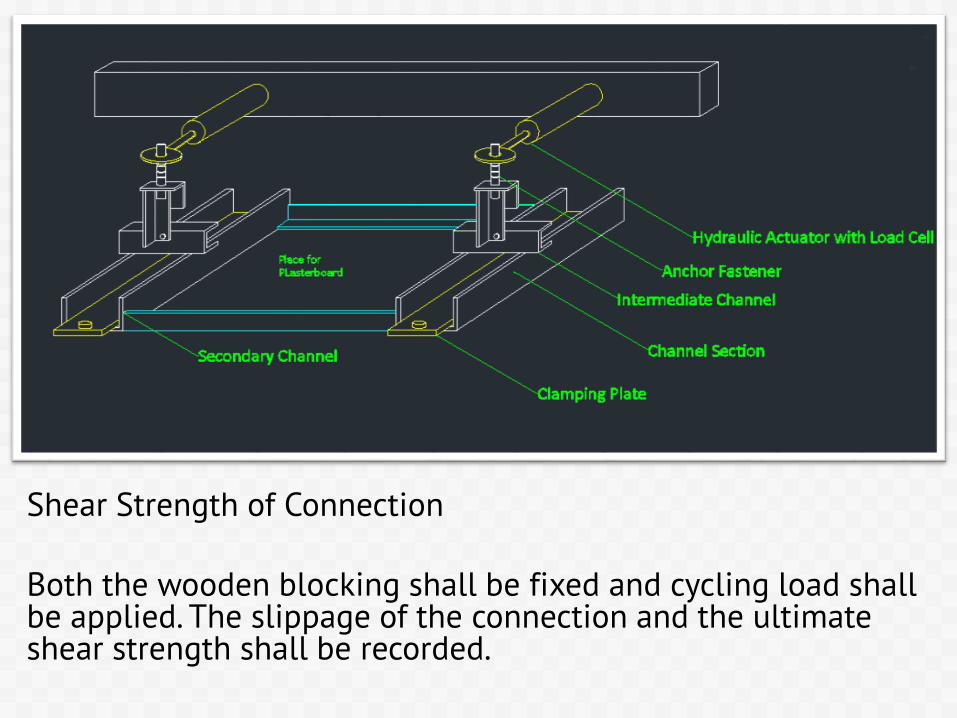
Shear Strength of Connection
Both the wooden blocking shall be fixed and cycling load shall be applied. The slippage of the connection and the ultimate shear strength shall be recorded.

Shear Strength of Plasterboard and Frame
One of the wooden blocking shall be released and the other shall remain fixed. Cyclic loads through one of the hydraulic actuators shall be applied to record results.

Shear Strength of Plasterboard and Frame
The displacements of interest are relative displacement between anchorages, slip between anchorage and the channels, and wall diagonal length change (shear deformation of the plasterboard).

Cyclic Load Application – 1
Sequential Phased Displacements Procedure.
The TCCMAR procedure defines the concept of the First Major Event (FME) as the first significant limit state that occurs during the test.

Cyclic Load Application – 1
Sequential Phased Displacements Procedure.
Consists of applying three cycles of fully-reversing displacement, at increments representing 25%, 50% and 75% of the FME.

Cyclic Load Application – 2
Large Excursion Displacement Sequence
Follows the TCCMAR incremental displacement guidelines but begins the test displacement at 200% of the FME.

Cyclic Load Application – 3
Reduced Cyclic Displacement Sequence.
The three cycles of displacement at 100% of the FME following the decay cycles are removed within each displacement increment.

Calculations
The hysteresis curves for all three sequences shall be plotted.
Based on the observed hysteresis response curves, the initial and the stabilized envelope (positive and negative) curves are generated for each tested specimen

Outputs
• Maximum Strength of Connection.
• Maximum Shear Strength, Vpeak
• Stabilized Shear Strength
• Secant Shear Modulus
• Ductility Factor

REPORTING AND DELIVERABLES
Correlations with deliverables
Problems in establishing relation
• The actual failure during an earthquake is modelled on a system scale and not component scale.
• The seismic zone classification is based on perceptual intensities.
• The structural frame design equations, if used on a component scale produce erroneous results.

Seismic Zone Correlation
• The Peak Ground Acceleration (PGA) is a measure of earthquake acceleration on the ground.
• Unlike the moment magnitude scales, it is not a measure of the total energy of an earthquake, but rather of how hard the earth shakes in a given geographic area (the intensity). This value can be related with the MSK scale which has been used to classify the seismic zones in IS 1893 – 2002

Seismic Zone Correlation
• The test designed can simulate X displacement of ± 100 mm, horizontal accelerations of ±14.715 m/s2 and velocities of 300 mm/s.
• Earthquakes of up to degree IX can be recreated using the equipment.

References
Other than those mentioned in the Standards section, the following have been referred to:
• http://www.gyproc.in/false-ceilings-professional.html • [2] http://www.ecophon.com/en/Product-Web/Advantage/Advantage-E/ • [3] http://www.gyproc.ae/pdf/Gyptone_Board.pdf - Gyptone Boards, Tiles and
Planks Technical Datasheet • [4] Experimental Cyclic Racking Evaluation of Light-frame Wood Stud and
Steel Stud Wall Systems, PHRC Research Series Report No. 107 • [5] IS 808 – 1989: Dimensions for Hot Rolled Steel Beam, Column, Channel and
Angle Sections • [6] IS 2095 (Part 1) – 1996: Gypsum Plaster Boards — Specification • [7] AD-AS264 261: Cyclic Load Testing of Unreinforced Masonry Walls • [8] Plasterboard Partitions Seismic Performance Evaluation via Shake Table
Test, G. Magliulo, C. Petrone, V. Capozzi, G. Manfredi, University of Naples Federico II, Department of Structural Engineering, Naples, Italy

THANK YOU
Questions?