seismic testing of sustainable composite cane and mortar ......and maintained bahareque houses have...
TRANSCRIPT

Seismic Testing of Sustainable Composite Cane and Mortar
Walls for Low-Cost Housing in Developing Countries
Institution of Civil Engineers
Research & Development Enabling Fund 2012
Arup and Imperial College London
Project Report
May 2013
A. Y. Elghazouli A. Lawrence
C. Málaga-Chuquitaype S. Kaminski
K. Coates

2
Executive Summary
Wattle-and-daub was a popular traditional housing style in many countries around the world,
and continues to be used in some developing areas. These buildings use local materials such
as timber, cane and bamboo to form a composite wall matrix, which is then plastered in mud
to form shear walls. Such houses are inexpensive, sustainable and relatively seismically-
resistant when well-constructed and free from damage such as decay and insect attack.
However, these constructions require a significant amount of maintenance. Also, wattle-and-
daub is not a popular housing choice for poor communities striving to achieve a better
standard of living, due to their association with low-income groups.
An engineered wattle-and-daub type technology has been developed in Latin America. This
construction type builds upon the traditional design but ensures the frame and wall matrix are
properly treated against insect attack, incorporates adequate details for the frame and base
connections and replaces the mud render with a cement mortar. Such houses have been tested
and built successfully in both Colombia and Costa Rica.
Arup and the NGO – REDES – have developed a local bespoke design for El Salvador,
which uses a timber frame clad with local cane. In order to characterise their seismic
response, an experimental investigation has been carried out at Imperial College London into
the behaviour of seven full-scale wall specimens subjected to cyclic loading.
The results from the tests suggest that cane and cement mortar walls behave compositely
under in-plane loads. The tests also showed that the proposed design is able to provide
reasonable capacity levels depending on the material properties. The behaviour of the wall
panel was observed to be stable and relatively predictable. The main failure mechanisms were
identified which include cracking and delamination, beginning at peak stress locations such
as the lintel beams and propagating throughout the panel. Importantly, the use of chicken
mesh ‘reinforcement’ proved useful in ensuring relatively safe failure modes appropriate for
use in house construction.
The results of these tests were used to propose a number of recommendations for the
construction of similar panels in low-cost houses.

3
Table of Contents
1.0 Introduction and Background 4
1.1 Introduction 4
1.2 Background to El Salvador 4
1.3 Existing Houses for Low-Income Communities in El Salvador 5
2.0 New Design Proposal 9
2.1 Overview of Design 9
2.2 Structural Design Method 10
3.0 Previous Research 11
3.1 Costa Rica 11
3.2 Colombia 12
4.0 Full-Scale Testing at Imperial College 14
4.1 General 14
4.2 Testing Methodology 14
4.3 Material Details 14
4.4 Construction of Panels 16
4.5 Experimental Set-up 17
4.6 Test Series 21
5.0 Experimental Results 22
5.1 General 22
5.2 Specimen 1 22
5.3 Specimens 2a and 2b 24
5.4 Specimen 3 28
5.5 Specimen 4 31
5.6 Specimen 5 34
5.7 Specimen 6 36
5.8 Specimen 7 40
5.9 Summary of Main Observations 42
5.10 Numerical Modelling 43
6.0 Conclusions 46
6.1 Concluding Remarks 46
6.2 Recommendation for Construction 46
6.3 Recommendations for Future Work 48
References 49

4
1.0 Introduction and Background
1.1 Introduction
This report summarises the experimental investigation into the behaviour of sustainable
composite bamboo and mortar walls under lateral cyclic loading, conducted at the Structures
Laboratories of Imperial College London. The research was funded by the Institution of Civil
Engineers 2012 Research and Development Enabling Fund with matched funding from Arup
and Imperial College London. The work is a joint collaboration between Imperial College
London and Arup.
1.2 Background to El Salvador
El Salvador is the smallest country in Central America, bordering Guatemala, Honduras and
Nicaragua. It is about the size of Wales, but with a population of 7.2 million people has the
highest population density of any country in the Americas. Although El Salvador is
approximately average in the World in the UN Human Development Index and the Human
Poverty Index (106th out of 180 countries in the Human Development Index), this masks its
position as the 32nd highest in terms of inequality, as measured by the Gini coefficient (World
Bank, 2012), and 12th highest in terms of ratio of average income of the richest to the poorest
(UNDP, 2009). This gap has been created by a combination of conflict, corruption and
frequent natural disasters.
Running through El Salvador across the East-West axis is a convergent tectonic boundary
between the Cocos and Caribbean Plate, putting El Salvador at risk not only from volcanoes
but also powerful earthquakes (López et al., 2004). Large earthquakes (> Magnitude 6) tend
to hit the country every 12 years, and the capital every 30. The infamous 2001 earthquakes
for example left almost 1200 dead, 1.5 million people homeless and had an economic cost of
$1.6 billion (Bommer et al, 2002) – many communities are still living in either makeshift
shacks or inadequate housing from this disaster. The El Salvadorean Seismic Code
(Asociación Salvadorena de Ingenieros y Arquitectos, 1997), divides the country into two
seismic zones along a crudely North-West to South-East running axis, with a Peak Ground
Acceleration (PGA) of 0.3g inland to the North and 0.4g South towards the coast associated
with a 475 year return period (10% probability of exceedance in 50 years) (see Figures 1 and
2).

5
Figure 1: Seismic hazard maps of Central America,
indicating PGA levels at 10% exceedance in 50
years (USGS 2012)
Figure 2: Seismic zones for El Salvador (Asociación
Salvadorena de Ingenieros y Arquitectos, 1997)
Volcanic eruptions are also a significant hazard, but due to early warning systems and good
evacuation protocols fatalities are usually very low.
El Salvador is also exposed to hurricanes which pass through the Caribbean and hit Central
America. Examples include Hurricane Mitch in 1998 which killed over 9000 people and
Hurricane Stan in 2005 which forced 67,000 into shelters nationwide.
Due to the warm tropical climate, termites and borer beetles are prevalent in El Salvador,
which softwoods, many hardwoods and all bamboo and cane are susceptible to.
The climate in El Salvador is tropical, with pronounced wet and dry seasons of average
rainfall per month over 300mm and under 20mm respectively, and temperatures typically
between 20-30 degrees Celsius (Weather and Climate.com, 2013). Timber, bamboo and cane
are all very susceptible to rot in this heavy rainfall and warm climate.
1.3 Existing Houses for Low-Income Communities
Within El Salvador there are three vernacular housing designs that are most common: wood
frames covered by palm fronds (rancho), unfired clay brick (adobe), and a derivative of
wattle-and-daub known as bahareque (in typical order of socio-economic status, lowest first).
All of these use local materials and are relatively cheap to construct. There are also a number
of common forms of more modern designs: wood frames covered by corrugated metal sheets
(lámina), reinforced brick masonry (mixto) and reinforced blockwork (López et al, 2004). See
Table 1 for a breakdown of the various construction types, and Figures 3 to 11 for views of
typical construction types.

6
Construction Type Urban Rural Total
Concrete or mixto (confined masonry) 84.5 46.1 71.2
Bahareque 1.5 8.8 4.0
Adobe 7.3 30.6 15.3
Timber 0.5 3.2 1.4
Lámina (metal sheeting) 5.4 8.5 6.5
Rancho (Straw, palm leaves or other plants) 0.2 1.2 0.5
Refuse 0.2 0.7 0.4
Other materials 0.5 0.8 0.6
Table 1: Wall construction type by % of total occupied houses in El Salvador (Ministerio de Economia &
Direccion General de Estadistica y Census, 2008)
Rancho houses are very simple and typically for those at the lowest economic level. They
have no predefined structure since they are in effect simple shacks, and therefore vulnerable
to earthquakes.
Adobe consists of unreinforced unfired mud bricks and a simple timber or bamboo roof. It is
inherently very poor seismically, although with recent research its performance can be
somewhat highly improved. Adobe is poorly regarded by low-income communities as it is
seen as a poor-man’s house, and due to its poor performance in recent earthquakes especially
after the 2001 earthquakes which destroyed over 110,000 adobe houses (32% of all adobe
houses in El Salvador) (Dowling, 2002).
Bahareque (also known as quincha in Peru, cuje in Cuba, pao pique in Brazil and tabiquería)
in other countries historically was more popular in wealthier and/or urban areas, and remains
in many older colonial and rural areas. This form of construction typically consists of a
timber or bamboo frame, clad in a matrix of cane, twigs or timber strips, and finally plastered
in manure or soil, sometimes with straw added for strength (Figures 3 to 7).
Historically, the roof was constructed from palm fronds, but switched to cooler yet heavier
tiles after the Spanish invasion of Central America (López et al, 2004). Properly constructed
and maintained bahareque houses have been shown to possess good structural unity and
flexibility, and therefore have a surprisingly high degree of seismic resistance (López et al.,
2004, and Gutiérrez, 2000). However, there are a number of potential issues with bahareque
that if not adequately addressed can lead to a reduced lifespan and possibly damage or
collapse in an earthquake:
1. Quality of construction: Bahareque is normally built by local skilled workers and short-
cuts are sometimes taken to save time and money.
2. Durability details: Well-constructed bahareque has good features such as a wall
elevated on top of a rock or brick upstand to reduce the risks of dampness, a good
overhang, and treated timber and bamboo (often with pig soap). However, while these
may reduce the risk of decay, damage due to termites and borer beetles is still common.

7
3. Roofing: Pre-colonial bahareque used palm fronds for the roofing, while the Spanish
introduced and then enforced clay tiles for the roofing – this change greatly increased
the dead loads on the roof and hence the seismic loads.
4. Maintenance: This is key to reducing damage from moisture, and replacing elements
damaged from insect attack, however in some cases the owners cannot afford
maintenance or are unaware of its importance.
Another important disadvantage of both adobe and bahareque is that they are prone to
harbouring insects, notably “the kissing bug” or chinche. This small biting insect can transmit
Chagas Disease, a potentially life-threatening illness that is estimated to currently affect 10
million people worldwide, mostly in Latin America (WHO, 2010). In addition, bahareque is
not endorsed by the seismic code of El Salvador and therefore does not attract the attention of
potential charities to sponsor housing projects.
Lámina houses are also very basic, and are unpopular because of the excessive heat that
builds up inside due to the metal façade. Mixto is relatively expensive to build due to the
materials required, and quality control during construction is particularly important to ensure
the concrete elements are well constructed and the steel tie reinforcement between the
columns and the panels is properly fitted.
The current most common engineered low-cost house that is being built post-2001 in El
Salvador is reinforced blockwork (see Figure 11), which consists of a simple single-storey
reinforced hollow-blockwork design. The foundations are simple strip footings and the roof is
normally of lightweight cement-fibreboard sheeting or zinc-aluminium sheeting. Tens of
thousands of these houses have been built all around the country, mostly by NGOs but also
some self-built, and they are generally popular with the beneficiaries due to their good
thermal mass, relatively low cost, good seismic performance and perceived social status.
However, these houses are difficult to construct in rural areas due to poor access, display
inherently brittle behaviour in earthquakes, use materials which have a large environmental
impact, and do not put any money back into the local micro-economy which could help to
address the social inequality within the country.
Figure 3: A typical shack, El Salvador (Kaminski,
2013)
Figure 4: Adobe house, El Salvador (Kaminski,
2013)

8
Figure 5: Lámina house, El Salvador (Kaminski,
2013) Figure 6: Míxto house, El Salvador (confined
masonry) (Kaminski, 2013)
Figure 7: Traditional Wattle-and-Daub, Latin
America (Casas-Aedo, W & Rivero-Olmos, 2013) Figure 8: Poorly maintained bahareque, El
Salvador (Kaminski, 2013)
Figure 9: Insect and rot damage to bahareque, El
Salvador (Kaminski, 2013) Figure 10: Well-maintained bahareque housing,
Colombia (Gutiérrez, 2004)

9
Figure 11: Reinforced blockwork house, El Salvador (Kaminski, 2013)
2.0 New Design Proposal
2.1 Overview of Design
The review presented in the previous section has highlighted the necessity to develop an
alternative low-cost housing design that can address the problems of the existing options,
which still prove to be cost effective. This new design must be seismically-designed and
cheaper or the same cost as the existing reinforced blockwork standard, and should be more
sustainable and put more money back into the local micro-economy. It should also be easy to
construct by the beneficiaries as part of a beneficiary-built program.
In order to achieve this, an engineered vernacular bahareque design was proposed (see
Figures 11 and 12), drawing on existing work in Colombia and Costa Rica. This design uses
the idea of bahareque but replaces the mud with cement render, properly treats all of the
timber and cane and engineers the connections, with the goal of having a seismically-
designed house with a minimum 30 year life-span. The new design has the following
characteristics:
• Single storey 3 or 4 room house.
• A lightly reinforced flat slab as a foundation.
• Two courses of reinforced hollow blockwork topped with a damp-proof membrane to
form an upstand to protect against insects and moisture.
• A treated pine or hardwood 2”x4” frame fixed with nails and light gauge galvanised
steel brackets. Vertical wall studs to be at max 600mm c/c.
• A treated cane (caña brava) wall matrix nailed to the timber (typically 20mm thick).
• Galvanised light gauge chicken mesh also nailed to the timber.
• A structural cement render wall finish to both sides of the cane (resulting in a total
wall thickness of around 60mm).
• A lightweight corrugated cement-fibreboard roof.

10
The combination of an upstand, DPM and a large roof overhang is expected to reduce the risk
of rotting of the cane or timber, while the treatment of the timber and cane will reduce the
risk of insect attack.
Figure 12: Prototype of new design constructed in
Bérlin, El Salvador, without render (The El
Salvador Project, 2012)
Figure 13: Completed prototype, Bérlin, El
Salvador (The El Salvador Project, 2012)
2.2 Structural Design Method
With negligible roof self-weight, the loads that the structure must resist will be wind
vertically on the roof (resisted by the timber frame and steel tie-downs to the walls), and wind
and seismic in both the in-plane and out-of-plane directions (seismic generated mostly by the
self-weight of the cement render). Assuming no significant ductility, the initial loads
generated in both the in-plane and out-of-plane direction were found to be governed by the
seismic demand, and an equivalent base shear factor of 1.0g was obtained for a 475 year
return period.
Due to no real composite action being likely in the out-of-plane direction between the timber
studs and the wall matrix, the studs are designed to carry the full out-of-plane load by
themselves, spanning between the double ridge beam and the reinforced upstand.
In the in-plane directions, all walls work as shear walls, transferring the shear down to the
reinforced upstand. It is expected that some shear flow will occur at the corners, resulting in
some benefit from the return walls acting as tension/compression flanges. Because flexibility
of the wall and door layout was deemed vital, the aspect ratios of the walls will vary,
resulting in some of the panels experiencing a net overturning load at a horizontal demand of
1.0g. Accordingly, tie-downs have been introduced in the corners of each wall intersection.
Although it can be considered that the walls will all work as shear walls, a proper
understanding of the actual behaviour under in-plane load is required to verify the design and
improve it accordingly. Precedence has been set by the numerous observations by engineers
regarding the good behaviour of bahareque in past earthquakes (López et al, 2004) including
the successful performance of 30 houses in Límon in Costa Rica after a large earthquake of

11
Magnitude Mw 7.8 resulting in local MMIs up to IX (Gonzalez, & Gutierrez, 2003). Previous
research has been carried out in Costa Rica and Colombia which will be summarized below.
3.0 Previous Research
3.1 Costa Rica
The Costa Rican National Bamboo Project (Proyecto Nacional de Bambú – PNB) was
established in 1988 with funds from the Netherlands and administrative support from the
United Nations Development Program (Gutiérrez, 2000). This project brought together
architects, engineers and bamboo specialists from across the world to develop and implement
an engineered form of bamboo bahareque for low-cost housing, which combined the local
vernacular form of hollow bahareque with bamboo bahareque technology from Colombia.
The aim of the project was to develop a cheaper and more sustainable form of housing.
In order to justify the design, in 1990 the Materials and Structural Models National
Laboratory of the University of Costa Rica constructed 13 engineered bahareque wall panels
and subjected them to monotonic in-plane load (Mendoza & Villalobos, 1990). The panels
consisted of a timber frame clad in either caña brava or esterilla and finally rendered with
cement mortar. These tests demonstrated that:
• The load capacity of the wall panels is considerably greater than the seismic load
demand from the Costa Rican code.
• Failure occurred by either buckling of the leading stud in compression or a tensile
failure of the rear stud.
• The cement render did not tend to spall, regardless of the use of chicken mesh.
In 2004, additional cyclic tests were conducted on similar specimens (Figure 14). This
research confirmed the original test results and suggested that the walls had some ductility
under cyclic loading. The stiffness degradation at increasing cycles and displacement levels
was documented (Gonzalez, & Gutierrez, 2003) (Figure 15, and Tables 2 and 3).
Further confirmation of the strength of these types of panels was obtained when a number of
newly constructed PNB houses survived a Magnitude Mw 7.8 earthquake in Límon in 1991,
with local MMI intensities (Modified Mercalli Intensity) of up to IX (Gonzalez, & Gutierrez,
2003). Based on these tests, it is considered that these wall panels tend to work compositely,
with the cement render taking most of the load as a diagonal compression strut, the wall
matrix controlling cracking and out-of-plane buckling and the timber studs taking the vertical
tension induced by the diagonal strut.

12
Figure 14: Set-up for cyclic in-plane testing of
wall panel in Costa Rica (Gonzalez & Gutierrez,
2003)
Figure 15: Hysteresis load displacement curves for
one of the wall panels tested in Costa Rica (Gonzalez
& Gutierrez, 2003)
Test Fill Fu
[kN]
∆ at Fu
[mm]
Failure
B-02 Bamboo 63 20 Anchors are withdrawn
BW-01 Bamboo with window opening 82 50 Timber beam at base is crushed through washers
C-02 Caña brava 157 60 Bending of foundation beam
C-03 Caña brava 161 60 Bending of foundation beam
Table 2: Costa Rican tests: failure loads, displacement and mechanisms for each test (Gonzalez &
Gutierrez, 2003)
Displacement level
[mm]
Test
B-02 BW-01 C-02 C-03
5 + 8.8 8.9 17.7 14.1
- 8.4 7.1 11.2 10.7
10 + 9.3 6.9 14.2 11.1
- 7.6 5.9 9.3 8.5
15 + 7.3 4.8 11.6 8.6
- 7.5 4.9 8.4 7.8
20 + 5.5 2.5 10.4 7.4
- - 4.3 7.6 6.3
30 + - - 8.3 7.1
- - - 6.8 5.2
40 + - - 6.9 6.9
- - - 5.0 4.2
60 + - - 5.5 -
- - - 4.2 -
Table 3: Costa Rican tests: stiffness values derived from the load-displacement curves for different
displacement levels in kN/mm (Gonzalez & Gutierrez, 2003)
3.2 Colombia
In 1999 a Magnitude Mw 6.4 earthquake struck what is known as the coffee-growing region
of Colombia, notably the cities of Armenia and Pereira, resulting in 300,000 people left
homeless (Tistl & Velásquez, 2002). After this event it was noticed that while the more
modern masonry and reinforced concrete buildings suffered significant damage and often
collapse, the vernacular bahareque style of housing fared significantly better (Trujillo, 2007).
As such, a number of NGOs and international development agencies implemented housing

13
reconstruction projects that principally used bamboo for the structure following the
bahareque style, but with engineering input and modern details. This interest spurred the
Colombian Earthquake Engineering Association to conduct research into engineered
bahareque, which included a series of wall panel tests.
Following this, the Construction Manual for Seismically-Resistant Housing using Mortared
Bahareque was published (Prieto, Mogollón & Farbiarz, 2002), to which some of the new
bamboo houses were designed (some of the projects were implemented before this new
research was completed). This work was based around the traditional form of bahareque that
uses esterilla nailed onto a guadua frame, but improved by engineering the joints and
replacing the mud or manure render with cement mortar.
The seismic testing conducted after the coffee-growing region earthquake in 1999 involved
monotonically-increasing racking tests on a variety of panels with different aspect ratios, with
and without in-plane bracing, using principally guadua clad in esterilla, fine steel chicken
mesh and cement render. The results of the tests were generally similar to those obtained in
Costa Rica.
Further testing has also recently been conducted on a full-scale two-storey braced engineered
bamboo house subjected to uni-directional dynamic loading from a shake table (Figures 16
and 17). This testing was successful, and the design was found to comply comfortably with
the Colombian seismic design code (Francisco-Correal, 2012).
Figure 16: Full-scale two storey house after uni-
directional shake table test at the University de los
Andes, Bogota, Colombia (Kaminski, 2013)
Figure 17: Inside view of tested house, Bogota,
Colombia (Kaminski, 2013)

14
4.0 Full-Scale Testing
4.1 General
This section presents and discusses a series of tests performed in order to examine the
behaviour of composite cane and mortar walls subjected to lateral cyclic loading. The aims of
this experimental campaign are to characterise the lateral response of these wall panels as
well as to study the influence of factors such as mortar strength, frame layout, stud size and
orientation, mortar thickness, cane spacing and the use of chicken mesh. Additionally,
preliminary estimations of ductility levels and failure mechanisms are reported.
4.2 Testing Methodology
Since the new house design relies on all walls of the house to contribute to its lateral stability,
including those with windows, the test will model a typical individual wall with a central
window (these walls are typically around 3m long due to the timber length available in-
country). Most walls will be connected to return walls, which are expected to contribute to
the flexural behaviour of the in-plane wall, and therefore a 1m return wall section will be
incorporated into the test.
Because the roof cladding and structure is comparatively light, the majority of the seismic
load attracted by the house will be generated from the self-weight of the walls, and therefore
the most appropriate and realistic method of modelling the lateral load would be by applying
a horizontal UDL along the height of the structure. However, since this is difficult to achieve
in practice, and in order to make the testing more comparable to other in-plane cyclic tests, a
horizontal point load will be applied along the length of the wall instead.
Because the self-weight of the test panel that provides a restoring moment is expected to be
less than the overturning moment generated by the lateral load, tie-down straps will be
provided in addition to the existing tie-down straps in the panel design itself. These will
encourage a shear failure to form instead of a flexural or overturning failure
4.3 Material Details
Cane
Two different canes were used: caña brava (which is the same cane to be used for the
houses) for the main structural walls for tests 2-7 and off-the-shelf bamboo for the first pilot
test and some of the less critical return walls. Importantly, due to availability constraints,
smaller and less representative bamboo was used for the pilot test (Specimen 1). Similarly, in
light of the low level of structural engagement observed for the cane on the return walls,
smaller bamboo was employed in the return-walls of latter specimens.

15
Caña brava
The cane used for the testing was Gynerium sagittatum, also known as caña brava in Costa
Rica and vara de castilla in El Salvador. This hollow giant reed can grow up to 14m high and
to a diameter of 40mm (Francis, 2009), although more typically it reaches 6-8m high with a
diameter at maturity of 10-30mm. From the outside caña brava looks nearly identical to
smaller diameter bamboos, sharing similar properties. No test data for caña brava is known
to the authors.
The caña brava for the testing was boron treated by dip diffusion and air dried for around 4
weeks before being shipped direct from Costa Rica. The canes were generally 3m long, with
an external diameter of 10-30mm and in good condition. The cane walls are strongest where
the diameter is thicker – where the diameter is thinner, nailing tends to split the cane fibres.
The treatment method is not expected to change the structural properties of the canes, and in
addition is the same as the expected method to be used on site when constructing the houses.
The cane from Costa Rica is not expected to vary structurally significantly from that typically
found in El Salvador.
Bamboo
The bamboo used for the testing was 12-14mm 4ft off-the-shelf bamboo.
Timber
The timber used for the testing was Grade C16 Scandinavian Pine, 2”x4” (planed to
1.5”x3.5”), pressure treated and kiln dried. The timber to be used for the actual design of the
houses is 2”x4” Grade 2 Southern Pine, planed to 1.5”x3.5”, pressure treated and kiln dried.
Because the timber frame is not expected to be working near failure and the strength and
stiffness properties of the two timbers are very similar, any difference is not considered
significant.
Cement Mortar
The cement mortar used for the testing was made with a simple sand and Portland cement
mixture. In order to consider the realities of construction in developing countries, a weak mix
was typically used to provide a lower bound of the strength of the panel. For example, the
typical sand:cement ratio was around 7:1 and the water:cement ratio used was higher than
might be expected for a conventional render – the latter was important since it is known that
both skilled and unskilled labour routinely add in extra water in hot climates in order to
improve workability, and controlling this is very difficult.
Strengths that were considered varied from 2 to 20 N/mm2 from cube testing, differing water-
cement ratios contributing most to the difference in strengths observed.
Chicken Mesh
The chicken mesh used for the testing uses lightweight steel wire with hexagonal 25mm
holes. The chicken mesh to be used for the house design is expected to be the same if not
denser than the mesh used in the testing.

16
Steel Ties
The steel ties used for the latter stud-to-sole plate tie-downs were Simpson Strong-Tie Light
Engineered Strap 600x100 straps. These have a tensile Safe Working Load of 4kN. The
straps for the house design are to be USP steel U-straps, gauge 18, with an allowable seismic
tensile capacity of 7.7kN.
Hurricane strapping
The steel ties used for the first stud-to-sole plate tie-downs were Simpson Fixing Band FB20
ties. These ties were 20mm wide and 0.9mm thick.
Nails
The nails used for the testing were as follows:
a) For the structure: round wire nails, 3.0mm dia., 75mm long. b) For the small diameter bamboo: 2.0mm dia., 50mm long.
For the caña brava: round wire nails, 2.0mm dia., 50mm long.
These nails are essentially the same type and size as those to be used on the houses.
4.4 Construction of Panels
The construction method for each panel was as follows:
1. Assemble timber frame.
2. Lay timber frame onto floor and nail cane on.
3. Nail chicken mesh onto frames (on later tests this was done before fixing the cane).
4. Assemble frames together on rig.
5. Apply cement mortar.
6. After 7-20 days, connect rig and test.
The following are various observations in relation to the different components of the panels:
Timber
The nailing did not split the timber at any location.
Cane
Where the cane was thin or the end distance short (<50mm), the cane often split when nailed.
This was purposely not replaced since it is expected that some of the cane will split during
construction on site.
Mesh
While the mesh was tied as tightly as possible, in some locations it was a little loose to the
wall – these were fixed with tying wire where particularly bad, however again this is
expected to be mildly representative of the finished product on site.

17
Mortar
The mortar was applied to the wall over between 3-10 days, depending on the manpower
available and the quality of the previous layer. The layers were typically as follows, and
match the procedure to be used on site for the final design:
1. First layer applied to the chicken mesh side of the panel. This layer needed to be
relatively dry in order to stick well to the mesh. Only one side could be applied at once
otherwise the mortar would be forced off the mesh by the other side’s layer.
2. Second layer applied to the other side of the panel. This layer could be wetter than the
first.
3. Third layer applied to both sides of the panel simultaneously. This layer could be wet.
4. Fourth and final layer applied to both sides of the panel simultaneously. This layer could
be wet. Final finish was made as smooth as possible in order not to introduce potential
weaknesses in the wall, and so that cracking could be easily seen during testing.
Application times between layers varied from 1-7 days, depending on manpower available.
Layers were cured by covering with a plastic sheet and normally spraying with water every
day for 3-5 days post-application. Between layers, the wall was roughened by scoring before
drying in order to provide a good key for the next layer. Before applying a new layer, the wall
was cleaned with a brush to remove any loose material and then dampened with water. The
mortar was applied by unskilled labour which is taken to be representative of the auto-
construction levels expected on site.
The application method used is considered generally representative of the type to be used in
El Salvador, with the main difference that in-country the ambient temperature during
application is typically 30-40 degrees Celcius, while the laboratory temperature for the
testing was approximately 20 degrees. This difference will encourage faster setting of the
mortar on site, however rapid evaporation of the moisture within the mortar may affect its
strength, as might the builder’s enthusiasm to add water back to the mix to compensate –
good quality control is essential to reduce the risk of both of these occurring.
4.5 Experimental Set-up
In order to evaluate the lateral response of the wall panels, a total of seven large scale tests
were performed on specimens with different structural and loading configurations. A
purpose-built test-rig was constructed to facilitate a versatile experimental assessment of
panels. The layout of the test-rig is depicted in Figure 18 and Figure 19. All Specimens were
fixed at the base to a steel rig by means of 10 mm steel bolts. The steel rig was constructed
from welded square hollow sections (SHS 100x10) pre-stressed to the strong floor as
depicted in Figure 18.
A hydraulic actuator operating in displacement control was employed to apply lateral forces
at a given height along the specimen. Different heights were considered throughout the
testing program as explained in the following sections. In order to facilitate a uniform load

18
distribution along the length of the panel, a loading beam formed of two parallel U100
Channel sections was employed as depicted in Figure 19. The loading beam was connected to
the Specimen via 10 mm bolts that were allowed to yield. Lateral restraint was provided by a
SHS100 column guiding the loading beam at its extreme as shown in Figure 19. Additional
panel lateral stability was supplied by the 1 metre-long perpendicular walls constructed at
each end of all Specimens.
Nominal vertical loading was applied at the beginning of the test by means of strong stressed
ties attached to the steel base as presented in Figure 20. The level of load was continuously
monitored by means of load cells attached to the top of the Specimen as can also be
appreciated from Figure 20 (right).
Lateral displacements and forces were recorded by the load cell and displacement transducer
incorporated within the actuator. Displacement transducers and string-potentiometers
installed at selected locations were used to monitor in-plane deformations and distortions. All
tests were conducted under displacement-control. The cyclic testing protocol shown in Figure
21 was used, where ∆ is the applied displacement and ∆y is the estimated yield displacement
similar to the EN12512 protocol (CEN, 2005).

19
Figure 18: Test-rig layout
Loading studs (10 mm diameter) U100 Loading beam
Base fixing studs
Floor bolt
3.050
0.635
Column
Bracing - lateral restraint
0.260 0.440
0.100
SHS 100x100x10
SHS 100x100x10Steel plate t= 10mm
0.260 2.750 0.440
1.500 1.000
0.220
Harnesses for vertical
load application
Specimen
Floor bolt
Fixing studs @ 0.12
25t Reaction frame
25t Actuator
Column - lateral restraint
Hinge
Specimen
Hinge
Strong Floor
Actuator
0.610 3.050 0.610
Variable
RIG ASSEMBLY PLAN VIEW
RIG ASSEMBLY ELEVATION
A B C

20
Figure 19: General view of test set-up
Figure 20: Details of the vertical ties and load cell
Figure 21: Loading protocol
-8
-6
-4
-2
0
2
4
6
8
0 4 8 12 16
Cycle number
.∆
/∆y
Specimen
Loading beam
Actuator
Column
(lateral restraint)
Vertical ties

21
4.6 Test Series
A total of seven large scale panels were tested. A summary of the test series is given in Table
4. After two test variations where the load application point was placed at the top of the panel
(in Specimen 1) and at the middle of the panel (in Specimen 2), the location of the actuator
and loading beam was kept constant at a height of 1.70 m for Specimens 3 to 7. Also, the
number of vertical ties was increased from 2 in Specimen 1 to 4 in Specimens 2 to 7 in order
to prevent an undesirable global overturning failure mechanism. Similarly, in order to avoid
shearing of the stud fixings (which can be determined easily through hand-calculations
therefore does not require testing), the number of 10mm dia. steel studs at the base of the
main panel was increased from 6 in Specimens 1 and 2 to 16 in Specimens 3 to 7.
Specimen 1 Specimen 2 Specimen 3 Specimen 4 Specimen 5 Specimen 6 Specimen 7
Panel No window
With 1m x 1m window
With 1m x 1m window
With 1m x 1m window
With 1m x 1m window
With 1m x 1m window
Independent walls
Loading Top of panel (18 studs)
Mid-height (18 studs)
Top of window (18 studs)
At top of window (14 studs), slotted
holes
At top of window (14 studs), slotted
holes
At top of window (14 studs), slotted
holes
2/3 up wall (7 studs per panel)
Vertical ties 2 (on main panel)
4 (on return walls)
4 (on return walls)
4 (on return walls)
4 (on return walls)
4 (on return walls)
2 per wall (on return walls)
Base shear fixing from sole plate to foundation
6 bolts 6 bolts 16 bolts 16 bolts 16 bolts 16 bolts 8 bolts per wall
Fixing from studs to sole plate, in addition to nails
Nailed 150mm stub, no straps
L-straps (return wall and window) and U-straps (to
all)
L-straps (return wall)
L-straps (return wall)
L-straps (return wall)
L-straps (return wall)
L-straps (return wall)
Cane in main panel Small-diameter bamboo
Caña brava Caña brava Caña brava Caña brava Caña brava Caña brava
Cane spacing (mm) 10-20 5-10 10-20 10-20 10-20 10-20 10-15?
Spacing between vertical studs (mm) 500 500 1000 1000 1000 1000 1000
Vertical stud strong axis orientation Out-of-plane Out-of-plane In-plane In-plane In-plane In-plane In-plane
Chicken mesh Outer face Outer face Outer face Inner face Inner face None Inner face
Mortar strength [Mpa] (number of samples)
Not obtained 11 (2) 5 (2) 5 (12) 12 (12) 3 (8) 3 (6)
Table 4: Summary of test series

22
5.0 Experimental Results
5.1 General
Table 5 summarizes the main results from the experimental programme. The initial stiffness
represents the tangent stiffness at small displacement levels whereas the maximum measured
force (Fmax) and its corresponding displacement (∆u) are also reported. Table 5 also includes
an estimate of the ultimate load (Fu) corresponding to the stage at which a significant
deterioration in strength was observed. Similarly, estimates of ductility were calculated as a
function of the ultimate displacement (∆u) and the displacement at which full plasticity was
achieved (∆u). The results for individual tests are presented and discussed in the following
sub-sections.
Maximum
Force, Fmax
Displacement
at Fmax
Displacement
at ultimate, ∆u
Ultimate
load, Fu
Estimated
ductility
Initial
stiffness
Test [kN] [mm] [mm] [% of Fmax] ∆u/∆p [kN/mm]
Specimen 1 53.2 10 NA - - 20
Specimen 2 77.4 35 40 79.8 2.7 20
Specimen 3 45.8 25 45 88.4 4.5 20
Specimen 4 42.1 25 45 89 4.5 18
Specimen 5 50.3 55 NA - - 14
Specimen 6 37.2 25 30 84.4 3 14
Specimen 7 27.7 35 - - - 7.6
Table 5: Summary of test results
5.2 Specimen 1
Description
Figure 22 presents a view of Specimen 1 which consisted of a single 3.00 m by 2.10 m panel
with two perpendicular one-metre wide walls at both ends. 18 equally spaced bolts (10 mm
diameter) were used to transmit the load from the loading beam at the top of the panel to the
panel itself. The specimen was fixed at its base to the steel rig by means of 6 10 mm steel
bolts on the main panel and 2 additional bolts on each perpendicular wall. All vertical timber
studs were nailed at their base as depicted in Figure 23. Importantly, vertical restraint was
provided by means of 2 tie-downs at the extremes of the main panel as can be appreciated
from Figure 22. Applying the load at the top of the panel is in line with typical in-plane tests,
however will increase the overturning load on the panel.
Results
The force-displacement curve at the actuator level obtained for Specimen 1 is presented in
Figure 24 whereas the corresponding vertical forces in the ties are shown in Figure 25. It can
be appreciated from both figures that the Specimen behaves nearly elastically until a force
plateau is developed starting at a lateral displacement of around ±15 mm due to overturning
failure of the panel. The base shear capacity of Specimen 1 was around 50 kN and the peak
vertical load reached 12 kN at maximum displacements. This overturning failure prevented

23
the development of the full shear lateral capacity of the panel. Figure 26 presents the typical
failure of the base of the panel at peak deformation (approximately 55 mm of lateral top
displacement).
Figure 22: General view of Specimen 1 before test
Figure 23: Detail of timber connections at the base in Specimen 1
Figure 24: Force-displacement hysteresis for Specimen 1
-60
-50
-40
-30
-20
-10
0
10
20
30
40
50
60
-70 -60 -50 -40 -30 -20 -10 0 10 20 30 40 50 60 70
Displacement [mm]
Forc
e [k
N]

24
Figure 25: Vertical forces in Specimen 1
Figure 26: Overturning failure in Specimen 1
5.3 Specimens 2a and 2b
Description
Figure 27 presents a view of Specimen 2 before testing. Specimen 2 included a 1.00 m by
1.00 m window within the main panel. It can also be seen from Figure 27 that the loading
beam in Specimen 2 runs through the middle of the panel while the vertical ties were moved
to the perpendicular walls and doubled up (2 at each side). Additional L-straps and u-straps
were employed to reinforce the timber connections at the end of the panels either side of the
window as presented in Figure 28. The combination of these two changes will halve the
overturning load for the same lateral load, and at the same time increase the capacity of the
panel to resist overturning, with the aim of forcing a shear failure to develop. In addition, the
repositioning of the tie-down straps was to avoid the risk of the pre-tensioning loads in the
straps affecting the results in the main panel (by enhancing the shear capacity). Lastly, caña
brava was used for all wall panels instead of small-diameter bamboo.
0
2
4
6
8
10
12
14
16
18
-70 -60 -50 -40 -30 -20 -10 0 10 20 30 40 50 60 70
Actuator Displacement [mm]
Ver
tica
l F
orc
e [k
N]
1
2
1 Actua tor
2

25
Results of Specimen 2a
Figure 29 presents the force-displacement relationship for Specimen 2 at the actuator’s height
for the first stage of testing denoted herein as Specimen 2a. Shear cracking started to develop
within the bottom part of the specimen at lateral displacements of 2-7 mm and continued
throughout the test. Mortar cracking was accompanied by deviations from linearity of the
force-displacement curves as presented in Figure 29. Shear failure of the steel studs
connecting the panel to the rig was observed during the first 25-mm cycle at a corresponding
lateral load of around 70 kN. Due to this failure, the specimen was unable to carry further
loads and the test was stopped. Figure 30 presents the state of Specimen 2a at the end of this
phase of testing.
Figure 27: General view of Specimen 2 before test
Figure 28: Detail of connections at the base on Specimen 2

26
Figure 29: Force-displacement hysteresis for Specimen 2a
Figure 30: Damage state of Specimen 2a after test. Outside (left), inside (right). The coloured lines show
the progressive cracking at each level of displacement
Results of Specimen 2b
Specimen 2a was demounted and 10 additional 10mm dia. bolts were installed to connect the
bottom of the panel to the steel base. Testing of the specimen was resumed after the
installation of the additional studs starting with cycles at ± 15 mm. The load-displacement
hysteresis obtained for this second stage of testing (referred herein as Specimen 2b) is
depicted in Figure 31. It is clear from this figure that Specimen 2b exhibited a stable cyclic
response with large levels of pinching. This pinching effect occurs due to the accumulation of
mortar cracking and residual plastic deformations within the timber frame connections. The
peak shear forces recorded are in the order of 75 and 80 kN at peak displacements of +35 and
-35 mm at mid-height, respectively. At this level of displacements, significant spalling of the
cement render of the inner face of the panel was also observed together with important
cracking in the outer face. This accumulation of damage marked a diminution in the
specimen capacity during the last cycles of loading as depicted in Figure 31. Overall views of
the Specimen damage at the end of the test are shown in Figure 32 and Figure 33 for the outer
and inner faces, respectively.
-85-75-65-55-45-35-25-15
-55
1525354555657585
-70 -60 -50 -40 -30 -20 -10 0 10 20 30 40 50 60 70
Displacement [mm]
Fo
rce
[kN
]

27
It is important to note that the drift distribution along the height of Specimen 2b was not
uniform. This can be further appreciated with reference to Figure 34 which presents the
absolute difference between the displacements measured at the top of the panel and at mid-
height. It is evident from Figure 34 that for mid-height displacements of 20 mm or higher, the
difference between top and mid panel deformations remains effectively constant, indicating a
low level of participation of the top part of the specimen above the loading apparatus. This
partial engagement is also reflected in the damage patters presented in Figure 32 and Figure
33.
Figure 31: Force-displacement hysteresis for Specimen 2b
Figure 32: Damage state of Specimen 2b (outer face) at the end of test
-85-75-65-55-45-35-25-15-55
1525354555657585
-70 -60 -50 -40 -30 -20 -10 0 10 20 30 40 50 60 70
Displacement [mm]
Forc
e [k
N]

28
Figure 33: Damage state of Specimen 2b (inner face) at the end of test
Figure 34: Difference between top and mid-height displacements in Specimen 2b
5.4 Specimen 3
Description
Figure 35 presents a general view of Specimen 3 before testing. In order to favour a more
uniform distribution of deformations along the height of the panel and more closely model
the real position of the net lateral load on the house, the loading system in Specimen 3 was
placed at 1.70 m from the strong floor (coinciding with the lintel of the window as can be
seen in Figure 35). Other changes included the reduction in the number of vertical timber
studs from the 3 at each side of the window employed in previous specimens (Figure 27) to
only 2 at either side of the window used in Specimen 3 (Figure 35). Also, the orientation of
the timber studs was varied, with the main axis of the timber studs aligned to the main panel
plane in Specimen 3. Similarly, all L-straps at the base were removed and only 3 L-straps
were left in the return walls at the extremes. These three changes were aimed to more closely
mirror the final house design.
0
2
4
6
8
10
12
14
16
18
20
-70 -60 -50 -40 -30 -20 -10 0 10 20 30 40 50 60 70
Displacement mid height [mm]
Ab
solu
te d
isp
lace
men
t d
iffe
ren
ce
top
to
mid
hei
gh
t [m
m]

29
Results
The cyclic response of Specimen 3 is depicted in Figure 36 while Figure 37 presents the
corresponding vertical loads. It can be seen from Figure 36 that Specimen 3 exhibited a stable
cyclic response with appreciable levels of pinching. The peak lateral forces were about 45 kN
and 51 kN for +25 and -27 mm of lateral displacement at the actuator height, respectively.
Observable deviation from linearity happened at around ±3 mm of lateral displacement
whereas significant non-linear behaviour was evident at around ±10 mm. Peak vertical forces
of around 5 kN were observed at maximum displacement demands as depicted in Figure 37.
Overall views of the damage in Specimen 3 at the end of the test are shown in Figure 38 and
Figure 39 for the outer and inner faces, respectively. Significant spalling of the mortar in the
inner face of the panel was observed starting at around +30 mm and continuing throughout
the test leaving large sections of bamboo exposed as shown in Figure 39.
Figure 35: General view of Specimen 3
Figure 36: Force-displacement hysteresis for Specimen 3
-60
-50
-40
-30
-20
-10
0
10
20
30
40
50
60
-70 -60 -50 -40 -30 -20 -10 0 10 20 30 40 50 60 70
Displacement [mm]
Forc
e [k
N]

30
Figure 37: Vertical forces in Specimen 3
Figure 38: Damage state of Specimen 3 (outer face) at the end of test
Figure 39: Damage state of Specimen 3 (inner face) at the end of test
0
2
4
6
8
10
12
14
16
18
-70 -60 -50 -40 -30 -20 -10 0 10 20 30 40 50 60 70
Actuator displacement [mm]
Ver
tica
l fo
rce
[kN
]
1
3
1 Actua tor 2
3 4

31
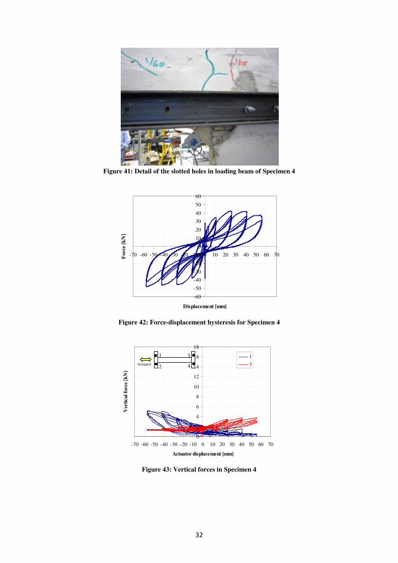
5.5 Specimen 4
Description
Figure 40 presents a general view of Specimen 4 before testing. It is important to note that the
chicken mesh reinforcement was moved to the inside (between the timber frame and the
bamboo) in Specimen 4 in order to test the effect of the chicken mesh on potentially
hazardous spalling. Additionally, the loading beam was not connected to the panel over the
section of the window in Specimen 4 whilst the steel beam holes were slotted as shown in
Figure 41. This was done in order to reduce artificial restraints imposed by the loading
apparatus which could act to inadvertently stiffen and strengthen the lintel portion of the
panel.
Results
The cyclic force-displacement relationship obtained for Specimen 4 is depicted in Figure 42
whereas Figure 43 presents the corresponding loads measured at the vertical ties. It can be
seen from Figure 42 that Specimen 4 exhibited a stable cyclic response with maximum lateral
forces reaching ±42 kN. As with previous specimens, cracking initiated around the corners of
the window at around ±7 mm of lateral displacement, whereas crushing of mortar in the
compression zones at the base of the panel was evident at ± 25 mm. It is also shown in Figure
43 that peak vertical forces of 5 kN were reached at maximum displacement levels.
Overall views of the damage in Specimen 4 at the end of the test are shown in Figure 44 and
Figure 45 for the outer and inner faces, respectively. Figure 46 shows close views of
damaged locations after testing. It is important to note that the provision of chicken mesh on
the inner face of the panel was effective in preventing spalling of the mortar even after
significant cracking had occurred as can be seen from Figure 46.
Figure 40: General view of Specimen 4
32
Figure 41: Detail of the slotted holes in loading beam of Specimen 4
Figure 42: Force-displacement hysteresis for Specimen 4
Figure 43: Vertical forces in Specimen 4
-60
-50
-40
-30
-20
-10
0
10
20
30
40
50
60
-70 -60 -50 -40 -30 -20 -10 0 10 20 30 40 50 60 70
Displacement [mm]
Fo
rce
[kN
]
0
2
4
6
8
10
12
14
16
18
-70 -60 -50 -40 -30 -20 -10 0 10 20 30 40 50 60 70
Actuator displacement [mm]
Ver
tica
l fo
rce
[kN
]
1
3
1 Actua tor 2
3 4

33
Figure 44: Damage state of Specimen 4 (outer face) at the end of test
Figure 45: Damage state of Specimen 4 (inner face) at the end of test
Figure 46: Details of damage at the end of the test in Specimen 4

34
5.6 Specimen 5
Description
Figure 47 presents a general view of Specimen 5 before testing. All geometric and structural
characteristics of the previous test (Specimen 4) were conserved in Specimen 5 except for the
mortar strength. The mortar strength was increased from 5.2 MPa in Specimen 4 to 11.5 MPa
in Specimen 5 by halving the sand:cement ratio, reducing the water:cement ratio, and
increasing the quality control and curing time.
Results
The cyclic force-displacement relationship obtained for Specimen 5 is presented in Figure 48
whereas Figure 49 presents the corresponding vertical loads measured at the ties. As
expected, the increment in the mortar strength has a direct influence on the maximum base
shear capacity of the panel which attained ±51 kN of maximum lateral load (20% more when
compared with the 42 kN of Specimen 4). However, despite the increment in the lateral
resistance of the panel, no significant change in the failure mechanism was observed. As with
previous specimens, cracking initiated around the corners of the window at ±7 mm of lateral
displacement in Specimen 5, whereas crushing of mortar in the compression zones at the base
of the panel was evident at ± 25 mm. With respect to the applied vertical forces, Figure 49
shows that peak vertical forces of nearly 7kN were attained at maximum displacement.
Overall views of the damage in Specimen 5 at the end of the test are shown in Figure 50 and
Figure 51 for the outer and inner faces, respectively. Figure 52 shows close views of the
damage observed on the lintel and window sections of the panel after testing. It is important
to note that the failure of the timber stud to the right of the window occurred during the ± 55
mm cycle and was caused by unavoidable stress concentrations brought about by the loading
system rather than a natural lateral (seismic) response of the panel – the effect of
concentrating the lateral load onto the horizontal timber beam, acted to load the studs
flexurally, at which point they failed. The wall also failed in shear along a line at the top of
the window, however this was exacerbated by the stress concentrations at the bolt holes
leading to crack propagation.
Figure 47: General view of Specimen 5

35
Figure 48: Force-displacement hysteresis for Specimen 5
Figure 49: Vertical forces in Specimen 5
Figure 50: Damage state of Specimen 5 (outer face) at the end of test
-60
-50
-40
-30
-20
-10
0
10
20
30
40
50
60
-70 -60 -50 -40 -30 -20 -10 0 10 20 30 40 50 60 70
Displacement [mm]
Forc
e [k
N]
0
2
4
6
8
10
12
14
16
18
-70 -60 -50 -40 -30 -20 -10 0 10 20 30 40 50 60 70
Actuator displacement [mm]
Ver
tica
l fo
rce
[kN
]
1
3
1 Actua tor 2
3 4

36
Figure 51: Damage state of Specimen 5 (inner face) at the end of test
Figure 52: Details of damage at the end of the test in Specimen 5. Lintel (left) and window timber stud
(right)
5.7 Specimen 6
Description
Figure 53 presents a general view of Specimen 6 before testing. Specimen 6 has the same
geometric characteristics of Specimens 4 and 5 but does not incorporate chicken mesh
reinforcement. This was done in order to investigate the response of these panels if the
chicken mesh reinforcement fully corrodes within the mortar.
Results
Figure 54 shows the cyclic force-displacement hysteresis obtained for Specimen 6. The initial
quasi-elastic stages are similar to those observed for Specimens 4 and 5 up until ±10 mm of
lateral displacement. From that point onwards, a relatively constant strength response was
developed with base shear values in the order of 33-37 kN. Delamination of both faces of the
panel started during the 10 mm cycles and continued until significant spalling of mortar on
both faces at the end of the test. The test finished after a 25% deterioration in the panel
capacity was evident during the first cycle at ±40 mm.

37
Figure 55 shows the evolution of vertical forces as measured in the ties against actuator
displacements. Maximum forces of nearly 5 kN and 7 kN were observed for ties Number 1
and 3, respectively. It is important to note the initial difference of 1kN between the two sides
of the panel which was unavoidable due to the tightening procedures.
Figure 56 presents a general view of the damaged state of Specimen 6 at the end of the test
for the outer face of the panel whereas Figure 57 presents the corresponding damage state for
the inner face. After this test was finalized, it was decided to remove all residual rendering
within the main panel and resume testing. This was done in order to evaluate the contribution
of the outstanding timber-bamboo frame to the overall lateral response of the panel. Figure 58
shows the state of the specimen after removal of rendering. The same loading protocol
defined in Figure 21 was employed for the subsequent test of the timber-bamboo structure.
Figure 59 presents the force-displacement relationship of the timber-bamboo frame of
Specimen 6 after removal of the rendering. It can be seen from Figure 59 that the contribution
of the timber frame to the full panel lateral response amounts to less than 15 %. A peak shear
force of 5kN was observed for maximum displacement demand levels of 70 mm.
Figure 53: General view of Specimen 6

38
Figure 54: Force-displacement hysteresis for Specimen 6
Figure 55: Vertical forces in Specimen 6
Figure 56: Damage state of Specimen 6 (outer face) at the end of test
-60
-50
-40
-30
-20
-10
0
10
20
30
40
50
60
-70 -60 -50 -40 -30 -20 -10 0 10 20 30 40 50 60 70
Displacement [mm]
Forc
e [k
N]
0
2
4
6
8
10
12
14
16
18
-70 -60 -50 -40 -30 -20 -10 0 10 20 30 40 50 60 70
Actuator displacement [mm]
Ver
tica
l fo
rce
[kN
]
1
3
1 Actua tor 2
3 4

39
Figure 57: Damage state of Specimen 6 (inner face) at the end of test
Figure 58: State of Specimen 6 after removal of rendering
Figure 59: Force-displacement hysteresis for Specimen 6 without mortar on the main panel
-6
-4
-2
0
2
4
6
-100 -50 0 50 100
Displacement [mm]
Forc
e [k
N]

40
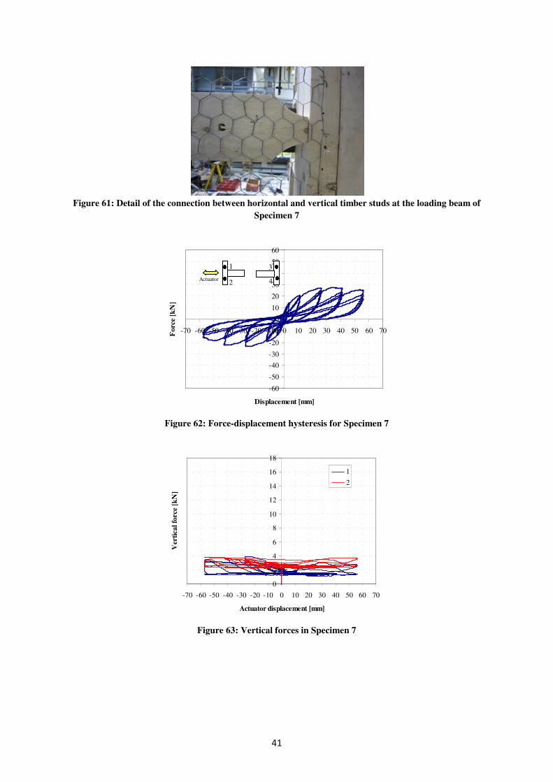
5.8 Specimen 7
Description
Figure 60 presents a general view of Specimen 7 before testing. It can be seen from this
figure that Specimen 7 is composed of two separate panels acting in tandem. The aim of this
Specimen is to determine the behaviour of a shorter panel, which is analogous to a typical
panel after the two coupling beams have broken down. Importantly, Specimen 7 incorporates
pinned connections between the horizontal and vertical studs at the location of the loading
beam that was incorporated in order to limit the transition of moments at these locations and
reduce the effect of the stiffness of the timber frame itself. Figure 61 presents a detail of the
pinned connection employed.
Results
The hysteretic response of Specimen 7 in terms of force-displacement relationship is
presented in Figure 62. A smooth transition between elastic and inelastic behaviour can be
appreciated from Figure 62 with a lateral strength capacity in the order of 25 kN. Crushing of
the mortar in the compression zones (bottom corners) was evident during the first 25mm
cycle whereas significant delamination of the rendering in the outer face was observed during
the third cycle at 25 mm amplitude. Shear cracking of the inner face started to develop at 40
mm of lateral displacement demand whereas extensive shear damage was observed during the
55 mm cycles. Figure 63 shows the evolution of vertical forces as measured in the ties against
actuator displacements. The vertical forces remained uniform throughout the test at values of
less than 4 kN.
Figure 64 presents a general view of the damaged state of Specimen 7 at the end of the test
for the outer face of the panel whereas Figure 65 presents the corresponding damage state for
the inner face.
Figure 60: General view of Specimen 7
41
Figure 61: Detail of the connection between horizontal and vertical timber studs at the loading beam of
Specimen 7
Figure 62: Force-displacement hysteresis for Specimen 7
Figure 63: Vertical forces in Specimen 7
-60
-50
-40
-30
-20
-10
0
10
20
30
40
50
60
-70 -60 -50 -40 -30 -20 -10 0 10 20 30 40 50 60 70
Displacement [mm]
Forc
e [k
N]
0
2
4
6
8
10
12
14
16
18
-70 -60 -50 -40 -30 -20 -10 0 10 20 30 40 50 60 70
Actuator displacement [mm]
Ver
tica
l fo
rce
[kN
]
1
2
1 Actua tor 2
3 4

42
Figure 64: Damage state of Specimen 7 (outer face) at the end of test
Figure 65: Damage state of Specimen 7 (inner face) at the end of test
5.9 Summary of Main Observations
A total of seven large scale specimens of composite cane and mortar panels were tested under
prescribed cyclic loading. From this set of tests, the following main observations can be
drawn:
• All specimens (except Specimen 1) observed a stable hysteretic behaviour with
smooth transition between elastic and non-linear response.
• All specimens presented significant levels of pinching that can be attributed to the
accumulation of plastic deformation in the connections and damage in the mortar.
• The number of L-straps and u-straps employed in Specimens 3 to 6 seem to be
sufficient to ensure adequate panel fixing at the base for the range of geometries and
loads studied.

43
• Chicken mesh reinforcement proved to be effective in preventing spalling of mortar
on the face to which it is attached. This effect was evident even after the panels had
accumulated significant cracking and damage.
• Chicken mesh reinforcement proved to be effective at retaining significant enough
portions of mortar on the wall for the mortar to still contribute to the strength and
stiffness of the panel.
• The contribution of the timber-bamboo frame without mortar in Specimen 6 reached 5
kN at maximum displacement demands, equivalent to less than 15% of the total
lateral resistance of the composite panel.
• As expected, the strength of the mortar stands in direct relationship with the lateral
capacity of the panel. A two-fold increment in the mortar strength (in Specimens 4
and 5) caused a 20% increase in the overall panel resistance.
• The cane, mortar, frame and chicken mesh all initially work compositely.
• The bond between the cane and the mortar is sufficient to provide some composite
action.
• Where the previous mortar layer was not well prepared by scoring, debonding often
occurred early. Where the previous layer was well prepared, debonding rarely
occurred.
• The beam above and below the window acts as a coupling beam.
• Failure of the panel typically occurs due to tension within the mortar, beginning in the
coupling beam and spreading to the side walls. Crushing of the mortar may also
occur.
• The method of application of the mortar and the spacing of the canes greatly affects
the strength of the wall panel, therefore quality control of the method of construction
is important.
5.10 Numerical Modelling
A number of preliminary numerical simulations were carried out in order to inform the
testing process and rig-design as well as to provide continuous feedback during the
experimental campaign. To this end, continuum Finite Element (FE) models were developed
in ABAQUS (2012) (Kontovazainiti, 2012). This section presents preliminary results from
such simulations.
In these models, the timber frame elements were represented by means of three dimensional
B31 beam elements. The mortar infill was modelled using quadrilateral four-node three
dimensional S4R shell elements. Material non-linearity in the mortar was taken into account
by means of the Concrete Damage Plasticity Model (ABAQUS, 2012) whereas equivalent
rebars were introduced to simulate the cane reinforcement. Contact phenomena between pairs
of interacting surfaces were modelled in accordance with the test set-up including non-linear

44
links to simulate the steel connections at the base. The material properties of the mortar
correspond to the values reported in Table 4 whereas nominal values were assumed for the
timber, cane and steel components. The models were subjected to increasing lateral forces
distributed along the line of loading specified during the experiments.
Figure 66: General view of the Finite Element model, Specimen 2 (Kontovazainiti, 2012).
Figure 67: Deformed shape of the Finite Element model of Specimen 2 (Kontovazainiti, 2012).
Figure 66 presents a general view of a typical FE model constructed to simulate the response
of Specimen 2 whereas presents the deformation pattern during a full plastic stage. It can be
seen with reference to and the corresponding experimental results depicted in Figure 32 and
Figure 33 that the model is able to faithfully represent the deformation mechanisms and
damage distribution observed during the experiment.

45
A typical comparison between the experimental force–displacement envelope and the
corresponding FE predictions is presented in Figure 68. It is evident from the plot in Figure
68 that the FE model provides a good prediction of the experimental stiffness. The strength of
the specimen is less well predicted due to variations on the mortar material properties as well
as the influence of the concentration of displacements in the vertical ties that were not
accounted for in the FE model.
Figure 68: Comparison of numerical force-displacement relationship and experimental envelope,
Specimen 1 (Kontovazainiti, 2012).
The numerical simulations carried out to date, have highlighted the two main contributions to
the system stiffness, namely the cement plastered walls and the connectivity between the
timber frame and the cement wall panel. In addition, it has been possible to conclude that the
proposed panel design can act compositely. These models also informed the design of the rig
and the dimensioning of the Specimens. Further studies are currently being carried out into
the refinement of the proposed FE models with a view to extend the experimental database
and explore the sensitivity of the response to additional design parameters.

46
6 Conclusion
6.1 Concluding Remarks
The results of the full-scale testing suggest that wall panels of small diameter cane/bamboo
and cement render work compositely to resist in-plane forces. However, the bond between
cane and the cement mortar is considerably worse than between reinforcement and mortar. In
addition, the cold joint created by rendering from either side separately contributes to create a
weak point from which delamination starts.
The simple low-cost panel design that has been developed is difficult to alter to incorporate
changes that would reduce the effects mentioned above. However, significant modifications
may not be required as the test results indicated that the capacity and ductility of the panel in
its current form will be adequate for typical design scenarios.
The tests indicate a range of ultimate strengths of a typical 3m wall panel with a window
from 37kN to 77kN, which are all greater than the design load of approximately 20kN
(equivalent to a design earthquake of 0.4g, conservatively assuming no reduction for
ductility). At ultimate loads, following failure of the coupling beam, the final failure
mechanism of the wall was found to involve cracking and delamination of the mortar, starting
from the base of the wall where the loads and deformations are greatest, and then propagating
upwards with increasing levels of deformation. The amount of spalling can be controlled by
the incorporation of a chicken mesh in construction.
6.2 Recommendations for Construction
Based on the results of this testing, the following are a list of recommendations for the
construction of future low-cost mortar and cane houses. Some of these recommendations will
apply to traditional vernacular bahareque houses as well.
- A minimum vertical stud spacing of ~500mm – more than this leads to deformation of
the canes during mortaring, which weakens the resulting bond.
- Horizontal infill timbers between studs at the connection to the sole plate is
recommended, as this provides a direct surface on which the studs can bear against –
nailing alone may not work well.
- Fixing the return wall to the in-plane wall with nails is crucial for allowing shear flow
and hence mobilising the return walls as flanges.
- Vertical tie-down straps from the end studs to the sole plate (and therefore to the
foundation) prevent pull-out, and are recommended, especially where there is no
significant return wall. Leaving these straps out may be adequate for the design
earthquake, however may result in pull-out in larger events.
- Vertical tie-down straps are typically not required either side of the windows for the
design earthquake. However, if the coupling beams experience damage, vertical tie-

47
down straps at the windows will considerably increase the resulting capacity of the
walls in-plane.
- A base fixing detail of bolts sized in shear for the design earthquake is sufficient.
- A minimum wall thickness of 60mm – this provides protection to the cane and is
adequate structurally.
- Canes should be 10-30mm in diameter.
- Canes should be well dried before fixing – although this makes them more susceptible
to cracking, otherwise they will dry and shrink away from the mortar. An alternative
is to fix the canes onto the frame and then leave them for a couple of weeks to air dry.
- Clear gaps between canes should be 10-15mm – greater than this leads to difficulty in
mortaring the first layer, and less than this leads to a weak structural bond.
- Canes must be continuous between studs. The canes are stiffest when they are
continuous over multiple studs, therefore long cane lengths are preferable.
- Canes must be nailed to each and every stud – a small nail diameter (e.g. 2mm) is
preferable to reduce the risk of splitting the cane.
- Chicken mesh is strongly recommended to be applied on the inside face of the
external walls, and on both faces of all internal walls, to prevent spalling (which helps
both structurally but importantly also for safety).
- Chicken mesh should be pulled tight and nailed to all studs and sole plates. Excess
mesh should be cut away to ease mortaring. Where the mesh is not tight up against the
cane, it should be tied onto the cane.
- Mortar should be protected from direct sunlight when curing, and should be regularly
sprayed with water for the first 7 days.
- Each mortar layer must be well prepared for the next layer by e.g. scoring – this is
essential.
- The surface of the previous layer should be cleaned to remove loose material, and
moistened, prior to application of the new layer.
- Each mortar layer must be well worked into the prepared previous layer.
- Mortar should be applied in layers <10mm thick – greater than this leads to a weaker
bond as the self-weight of the mortar pulls itself away from the wall.
- Well-graded sand in the mortar provides a much better finish and is easier to work
with.
- A sand-cement ratio of 6:1 or less is recommended – higher cement content will lead
to a higher strength.
- A high water content in the mortar will lead to a mix that is considerably easier to
apply and work into the gaps. Although this will lead to a weaker mix, the strength of

48
the panel is still likely to be adequate for the design earthquake, and ease of mortar
application leads to a better bonded panel.
6.3 Recommendations for Future Work
The findings presented in the previous sections have highlighted the potential advantages of
employing cane mortar composite panels to build low-cost earthquake-proof houses in
developing countries. The experimental results provide direct assessment of the number of
geometric and loading parameters, and represent valuable validation data for the purpose of
future numerical and design models. The studies carried out have suggested the need for
further research in the following areas:
- Additional in-plane cyclic tests, aimed at evaluating the influence of a number of
design modifications and optimizations ought to be conducted. Such modifications
should include the utilization of chicken mesh on both sides of panel, primer or bond
material placed over the cane to improve the bond to the cement render, different
retrofitting alternatives, etc.
- Also, the effects of different loading protocols on the panel structural response
parameters should be studied. This may include testing protocols with increasing
versus decreasing amplitudes and different number of cycles.
- Similarly, the characterization of the out-of-plane seismic response of composite cane
mortar panels is required.
- Full-scale shake table testing of a cane/bamboo and cement render house would be
desirable in order to test its global behaviour under dynamic loading.

49
References
Abaqus 6.10 Documentation. Modelling and Visualization. Abaqus/CAE, User’s Manual.
Part I: Interacting with Abaqus/CAE. [Online] DS Simulia. Available from:
https://www.sharcnet.ca/Software/Abaqus610/Documentation/docs/v6.1
0/books/usi/default.htm [Accessed August 2012]
Asociación Salvadorena de Ingenieros y Arquitectos (ASIA) (1997) Norma tecnica para
diseno por sismo (El Salvadorean seismic code). Ministerio de Obras Publicas, El Salvador
Bommer, J., Benito, M., Ciudad-Real, M., Lemoine, A., López-Menjívar, M., Madariaga, R.,
Mankelow, J., Méndez de Hasbun, P., Murphy, W., Nieto-Lovo, M., Rodríguez-Pineda, C.,
Rosa, H. (2002) The El Salvador earthquakes of January and February 2001: context,
characteristics and implications for seismic risk. Soil Dynamics and Earthquake Engineering
22 pp389-418.
Casas-Aedo, W, Rivero-Olmos, (2013) A Wattle and Daub Anti-seismic Construction
Handbook [Online] Available at:
http://www.misereor.org/fileadmin/redaktion/Wattledaub%20handbook%20anti-
seismic%20construction.pdf [Accessed: May 2013]
CEN (2005) EN12512, Timber structures – Test methods – Cyclic testing of joints made with
mechanical fasteners CEN Brussels.
Dowling, D. (2002) Adobe housing in El Salvador: Earthquake performance and seismic
improvement. Soil Dynamics and Earthquake Engineering 22 pp281-300.
The El Salvador Project (2012) [Photographs] (The El Salvador Project’s own private
collection)
Francis J. (2009) Housing Gynerium sagittatum information. [Online] Available from:
http://www.fs.fed.us/global/iitf/pdf/shrubs/Gynerium%20sagittatum.pdf [Accessed June
2012]
Francisco-Correal, J. (2012) Personal Communication
Gonzalez, G., Gutierrez, J. (2003) Cyclic Load Testing of Bamboo Bahareque Shear Walls
for housing protection in Earthquake Prone Areas. Materials and Structural Models National
Laboratory, School of Civil Engineering, University of Costa Rica
Gonzalez, G., Gutierrez, J. (2003) Cyclic Load Testing of Bamboo Bahareque Shear Walls
for housing protection in Earthquake Prone Areas. Materials and Structural Models National
Laboratory, School of Civil Engineering, University of Costa Rica

50
Gutiérrez, J. (2000) Technical Report 19: Structural adequacy of traditional bamboo housing
in Latin America. Beijing, INBAR
Gutiérrez, J. (2004) Notes on the seismic adequacy of vernacular buildings. In: 13th World
Conference on Earthquake Engineering. Vancouver, Canada, August 1-6 2004, Paper No.
5011
Kaminski, S. (2013) [Photographs] (Sebastian Kaminski’s own private collection
Kontovazainiti (2012) Numerical assessment of composite bamboo walls, MSc Dissertation,
Imperial College London
López, M., Bommer, J. & Méndez, P. (2004) The Seismic Performance of Bahareque
Dwellings in El Salvador. 13th World Conference on Earthquake Engineering. Vancouver
López, M., Bommer, J. & Pinho, R. (2004) Seismic hazard assessments, seismic design
codes, and earthquake engineering in El Salvador. Pp 301-320
Mendoza, H. & Villalobos, C. (1990) Capacidad Estructural de Paneles de Bambú.
Graduation Project, University of Costa Rica. School of Civil Engineering
Ministerio de Economia & Direccion General de Estadistica y Census (2008) VI Censo de
Pobulación y V de Vivienda 2007 [Online] Available from: http://www.bcr.gob.sv
[Accessed March 2010]
Prieto, S., Mogollón, J. , Farbiarz, J. (2002) Manual for earthquake-resistant construction of
one and two storey houses with cemented bahareque. Proceedings of the International
Workshop on the Role of Bamboo in Disaster Avoidance. Guayaquil, Ecuador, 6-8 August
2001, pp.149-166
Tistl, M., Velásquez, J. (2002) Roofs instead of tends: a reconstruction project in the
Colombian Coffee Zone after the Earthquake of January 25th, 1999. Proceedings of the
International Workshop on the Role of Bamboo in Disaster Avoidance. Guayaquil, Ecuador,
6-8 August 2001, pp.140-148
Trujillo, D. (2007) Bamboo structures in Colombia. The Structural Engineer, March 2007,
pp.25-30
UNDP (2009) United Nations Development Programe, Human Development Report 2009.
Palgrave Macmillan, New York
USGS (2012a) United States Geological Survey, Central America Seismic Hazard Map.
[Online] Available at:

51
http://earthquake.usgs.gov/earthquakes/world/central_america/gshap.php [Accessed: July
2012]
Weather and Climate.com (2013) World Weather and Climate Information. [Online]
Available from http://www.weather-and-climate.com [Accessed May 2013]
WHO (2010) Fact sheet 340: Chagas disease. [Online]. Available at:
http://www.who.int/mediacentre/factsheets/fs340/en/index.html [Accessed: July 2012]
World Bank (2012) Data. [Online] Available from: http://data.worldbank.org. [Accessed May
2013]