select from a truly outstanding range of world leading ... gb/wiuk catalogue 2012.pdf · 5 •...
TRANSCRIPT

Select from a truly outstanding rangeof world leading products

2
At Watts Industries, we’re focused not only on water,plumbing and heating, valves and controls, but agreat deal more. We are dedicated to developing
the most innovative products. It’s what wespecialise in.
This commitment has driven the company since itwas founded in 1874. It’s led to us firmly establishing
ourselves as one of the world’s premier manufacturers ofvalves and controls.
Watts has 55 facilities and 6,500 employees around the globe, with state-of-the-art manufacturing plants located throughout Europe, North Americaand Asia. We have also developed an impressive strategic warehousingand distribution network to ensure the cost-efficient distribution of ourproducts to customers in a variety of industries.
Watts – the name for quality products in the UK
Whilst you may already have heard of our name, you might besurprised to discover just how extensive our capabilities are, and thedepth of service Watts can now offer - to original equipmentmanufacturers and wholesalers in the UK.
Over the last few years, we’ve made majorinvestments to our distribution service and addedhighly respected tube manipulation andelectronic controls companies to the WattsIndustries UK family.
We can now claim to offer one of the largest andmost diverse plumbing, heating andwater quality product lines available –anywhere. And we can justly claim toserve some of this country’s biggestwholesalers.
Watts. You’re about to hear a lot moreabout us.
Watts. It’s a name you’ll recognise no matter whatarea of industry you’re involved in, and wherever
you are situated in the world.
And no wonder. Because as well as being aroundfor over 100 years, we’ve also developed a
reputation as a global leader in the field.
OVER 20 MANUFACTURING LOCATIONS IN EUROPE

3
WATTS INDUSTRIES IS FOCUSED
ON CUSTOMER COMFORT, SAFETY
AND PROTECTION
WE HAVE 55 FACILITIES
WORLDWIDE, 6500 EMPLOYEES
AND OVER $1.2 BILLION ANNUAL
SALES
WE HAVE A PRODUCT PORTFOLIO
OF MORE THAN 4000 PRODUCTS,
WHICH ARE DISTRIBUTED
WORLDWIDE
WATTSTHE NAMEBEHIND AWORLD CLASSCAPABILITY

4
If you’re an OEM or a wholesaler in this country, andyou deal with related products in any way, then theWatts name will be very familiar to you.
What you probably don’t realise though is just howextensive our plumbing, heating and water
quality product range is. Or precisely how muchsupport we can offer in bringing you the
specialist quality-tested solutions you need.
Whatever your requirement, as the marketing,sales and distribution company for Watts Industries products withinthe UK and Ireland, we’re here to help you.
Backflow preventers
Watts Industries is the world leader in backflow prevention devices.
Sanitary products
We’re a key manufacturer and supplier of pressure reducing valves,thermostatic mixing valves, safety valves and safety groups.
HVAC products
Solar ...air conditioning...fuel and gas...if it’s a HVAC application thenWatts has just the quality products you’re looking for.
Our recent acquisition of Swansea-based Team Precision alsomeans we now have unparalleled experience in the custom design,manufacture and supply of manipulated tubing.
Instrumentation
Plus we offer a complete range of instrumentation products.
With more than 20 Watts Industries productionplants and sales offices throughout Europe,
including 15 ISO-certified manufacturing facilities,and an annual turnover over EUR 500 Million,we’ve already made a big name for ourselves
among wholesalers and OEMs across thecontinent. Now it’s time for the UK to sit up and
really take notice.
WORLD WIDE SALES IN EXCESS OF $1.2BN

5
• AUTOMATIC CONTROL VALVES
• BACKFLOW-PREVENTERS
• BALANCING AND CONTROL VALVES
• CHECK VALVES
• EXPANSION VESSELS
• FILTERS AND STRAINERS
• GAS AND FUEL VALVES
• INSULATED PEX PIPE
• MANIFOLDS AND FITTINGS
• MEASURING GAUGES
• PRESSURE REDUCING VALVES
• RADIATOR ACCESSORIES
• SAFETY VALVES AND UNITS
• SHUT-OFF VALVES
• SYSTEMS AND SYSTEM PRODUCTS
• THERMOSTATS AND TEMPERATURE
CONTROLLERS
WATTSTHE NAME FOR TRIED ANDTRUSTED TECHNOLOGY

6
Think of Watts. Think of the one-stop shop.
Having recently doubled the size of our centralised storage anddistribution facility in Evesham, we are perfectly positioned to provideyou with the essential plumbing, heating and water quality productsyou need, fast.
In every single way, Watts delivers.
Watts the name for service and support
The staff at Watts Industries UK all have a background inthe industry and are ready to help you find the most suitable and
cost effective solutions possible.
We have experienced customer service specialists waiting to guide youthrough our product range and give you informed advice, whilst fullsupport is available across our entire product offering with a widevariety of publications and CD ROMs.
You can also be sure that the products we supply are competitivelypriced. That’s because, as a major player in the market, we arecommitted to low cost manufacturing andinvesting in product development.
No wonder Watts is working closelywith some of the biggest wholesalersand distributors in the UK.
At Watts Industries UK we treat our relationships withcustomers as a partnership. We listen to your needs.
We get to understand the problems and issues youface. And by drawing on our experience and the vast
resources at our disposal we work closely with ourcustomers to find the most effective solutions possible.
OVER 4,000 PRODUCT LINES AVAILABLE IN STOCK
Antipollutiondevices

8
ANTIPOLLUTION DEVICES
EXAMPLE OF APPLICATION
1
2
3
3
4
1 Backflow preventer unit.2 Backflow preventers with unregulated pressure zone.3 Anti-siphon devices.4 Anti-siphon devices for watering taps.
Please note: The diagram is for illustrative purposes only; for guidance on specific applictions please refer to theWater Regulations Manager at your local water company.

9
ANTIPOLLUTION DEVICES
Modern and safe solutions for our drinking water
Water is one of our most vital resources. Protecting our waterquality is crucial to ensuring clean and safe drinking water forthe future.
We use and distribute our water for many different purposesvia a public water supply network that is becomingincreasingly more complex. Consumers from all walks of lifeare connected to this network, which entails significantcontamination risks for water supply and distribution systems.A challenging environment such as this calls for innovativeand watertight security solutions that meet today’s demands.A challenge that Watts Industries is fully capable of meeting.
BA BS and BA BM: the new standard in BA drinking water protection
Watts Industries backflow prevention devices BA 009 and BA 909 are usedworldwide to protect public water supply systems from contamination by backflowof liquids in hazard category 4, as defined in EN 1717.
To meet the new European and UR legislation and product specifications in thisarea, Watts Industries introduced the BA BS backflow prevention device in thedimensions DN 6, DN 8 and DN 10. The BA BS is designed specifically for lowflow rate applications.
With its new BA BM, in the dimensions DN 15 to DN 50 inclusive, Watts Industriesoffers a complete range of backflow prevention devices that meets therequirements set out in the European standards EN1717 and EN12729 forprotection of drinking water systems from backflow.
Public water supply network with a large number of consumers

10
ANTIPOLLUTION DEVICES
RPZ BACKFLOW PREVENTERS – THREADED
STANDARD
The BA BS has been developed in compliance with EN1717 and EN12729.
Installation guidelinesThe BA BS is to be installed according to your national installation guidelines.
BA BS material specificationsBody DZR brass CW602NRelief valve body Plastic (PA)Seal RubberTundish PlasticConnections DZR brass
BA BS technical specificationsMax. system pressure PN 10 (10 bar) Nom. operating temp. 65°CPeak temperature 90 °C for 1 hour/day
BA BS approvalsKiwa, WRAS, NF, Belgaqua
Model BS DN Unit DeviceBA BS 006 6 405006311 405006010BA BS 008 8 405008311 405008010BA BS 010 10 405010311 405010010
DRUKVERLIESCURVE BA BS006/008/010
0
10
20
30
40
50
60
70
80
90
100
110
120
130
140
150
0 0,2 0,4 0,6 0,8 1 1,2 1,4Flow [m3/h]
Del
taP
[kP
a]
EN12729 BS006 BS008 BS010
01ND8NDDN6
BS006
BS010
BS008
Overall dimensions
Article numbers
BA BS pressure loss curve
Cutting edge materials and technology
• Dezincification resistant brass (DR).• Piston-driven relief valve, designed to reduce breakdown and maintenance and extend
useful life of device. The absence of a diaphragm ensures that only a small area of therubber surface will come in contact with potable water, reducing potential for excesssediment accumulation in device.
• A tundish, for draining out water and keeping floor dry.

11
ANTIPOLLUTION DEVICES
RPZ BACKFLOW PREVENTERS – THREADED
The new BA BM range was developed to complement the BA BS range in order to satisfy thenew European legislation and product specifications for backflow prevention devices that protectdrinking water systems from backflow of liquids in hazard category 4, as defined in EN1717.
StandardThe BA BM is developed in accordance with EN1717 and EN12729.
Installation guidelinesThe BA BM is to be installed according to your national installation guidelines. Valve supplied aseither a unit which includes strainer and isolating ball valves or as a device which is the valve onits own. Valves must be tested on an annual basis by a qualified tester. www.wras.co.uk
BA BM TECHNICAL SPECIFICATIONS
BA BM Unit 015 020 025 032 040 050Connections (male) R inch ½” ¾” 1” 1 ¼” 1 ½” 2”Tundish connection (female) D mm 32 32 40 40 50 50Overall length excl. connections L1 mm 122 122 157 157 220 220Overall length incl. connections L2 mm 201 201 252 252 336 336Height H1 mm 168.5 168.5 238 238 303.5 303.5Height H2 mm 103 103 156 156 202.5 202.5Height H3 mm 65.5 65.5 82 82 101 101Width W mm 53 53 76 76 115 115Weight, incl. connections L kg (+/-) 1,2 1,2 2,7 2,7 6,5 6,5and tundish
Overall dimensions
BA BM material specificationsBody DZR brass CW602NRelief valve body Plastic (PA) 1st and 2nd check valve module Plastic (POM)Seal RubberTundish PlasticConnections DZR
BA BM technical specificationsMax. system pressure PN 10 (10 bar)Nom. operating temperature 65°CPeak temperature 90°C for 1 hour/day
BA BM ApprovalsKiwa, WRAS, DVGW, NF, Belgaqua
Model BM DN Unit DeviceBA BM 015 15 405015311 405015310BA BM 020 20 405020311 405020310BA BM 025 25 405025311 405025310BA BM 032 32 405032311 405032310BA BM 040 40 405040311 405040310BA BM 050 50 405050311 405050310
STR
Stop Strainer BA device Stop valvevalve with tundish
DRUKVERLIESCURVE BA BS006/008/010
0
10
20
30
40
50
60
70
80
90
100
110
120
130
140
150
0 0,2 0,4 0,6 0,8 1 1,2 1,4Flow [m3/h]
Del
taP
[kP
a]
EN12729 BS006 BS008 BS010
01ND8NDDN6
BS006
BS010
BS008
BA BM pressure loss curve Article numbers

12
ANTIPOLLUTION DEVICES
RPZ BACKFLOW PREVENTERS – THREADED / FLANGED
RPZ 009 – PROTECTION BA
Backflow preventer designed to protect potable water supplies in accordance with nationalplumbing regulations and water company requirements up to Fluid Category 4.
Comprising two in-line, independent check valves, captured springs and replaceable checkseats with an intermediate relief valve in a bronze body, supplied with Y type strainer and twoisolating ball valves, with screwed BSP female end connections.
Max. operating pressure 12 bar. Operating temperature range 1ºC to 80ºC.
Type Part number Size body Box QtyRPZ009 EDP0062095 1/2” 1RPZ009 EDP0063031 3/4” 1RPZ009 EDP0063021 1” 1RPZ009 EDP0062950 1-1/4” 1RPZ009 EDP0062952 1-1/2” 1RPZ009 EDP0063011 2” 1
Type Part number Size body Box QtyTundish EDP0881399 1/2”-3/4” 1Tundish EDP0881376 1”-1 1/2” 1Tundish EDP881378 2”-3” 1
Tundishes to suit above valves
Backflow preventer designed to protect potable water supplies in accordance with nationalplumbing regulations and water company requirements up to Fluid Category 4.Comprising two in-line, independent check valves, captured springs and replaceable checkseats with a high discharge capacity relief valve in an epoxy coated cast iron body, flangedPN10 end connections.Max. operating pressure 12 bar. Operating temperature range Min. 1ºC to Max. 60ºC.
RPZ 909 – PROTECTION BA
Tundishes to suit above valves
Type Part number Size body Box QtyRPZ909 EDP385943 2-1/2” 1RPZ909 EDP385945 3” 1RPZ909 EDP385934 4” 1RPZ909 EDP385935 6” 1RPZ909 EDP385596 8” 1RPZ909 EDP385615 10” 1
Type Part number Size body Box QtyTundish EDP881378 2”-3” 1Tundish EDP0881385 4”-10” 1

13
ANTIPOLLUTION DEVICES
BA BACKFLOW PREVENTER TEST KITS
BACKFLOW PREVENTER, ANTI-SIPHON VACUUM BREAKER DEVICES
Differential electronic pressure gauge for monitoring differential pressures and checking forcorrect operation of BA backflow preventers during normal yearly maintenance. Compact andpractical device, easy to use. Maximum accuracy in measurement (error 0.25%) with reading ofdata on liquid crystal display. Indicator of battery consumption and automatic stop of the gaugeafter 15 minutes of non-use. High impact and water-tight ABS case. Corrosion-resistantstainless steel needle valves, with interchangeable seats. Stainless steel (316) protectionstrainer (100µ). Max. pressure: 14 bar. Max. temperature: 99°C. Complete with brass fittings and adapters.Three flexible pipes, size 91cm, in different colours and with Female Flare fittings. Supplied with two alkaline batteries type C to ensure a back-up time of 400 running hours.
TK99D DIGITAL
Type Part number Box QtyTK-99D PSI EDP385516 1TK-99D KPA EDP385518 1Carry case EDP0385508 1
Backflow preventer, non-verifiable disconnecter with different pressure zones, built-in filter.WRAS approved to Category 3. Commonly used to directly connect appliances such asdomestic heating boilers up to 45 kW permanently to a mains supply. DZR brass body, EPDMdiaphragm with stainless steel internals. Female union ends.Max. operating pressure: 10 bar. Operating temperature range: Min. 1ºC Max. 65ºC.
Protection : CAAccording to WRAS, KIWA-NL, ANSEAU, ASSE, CSA.WRAS approval applies to part numbers 30215, 30115 and 30138.
TYPE CA
Type Part number Size body Box QtyPlain brass + air gap 30115E 1/2” 1Nickel plated + air gap 30157 1/2” 1Plain Brass + air gap 30215 3/4 1
Mechanical differential pressure gauge for monitoring differential pressures and checking forcorrect operation of BA backflow preventers during normal yearly maintenance. Compact and portable device.Max. pressure: 12 bar. Max. temperature: 100ºC.Gauge diameter 100mm range 0 –15 psid and 0 – 1 bar with a ± 2% accuracy full scale.Three Flexible hoses, 1 metre long, colour coded with Female Flare fittings.The unit is supplied with a rugged, lightweight, shock resistant carrying case.
TK-9A MECHANICAL
Type Part number Box QtyTK-9A EDP385496 1

14
ANTIPOLLUTION DEVICES
DOUBLE / SINGLE CHECK VALVES
DZR brass body with copper compression and screwed BSP female end connections.
WRAS approval applies to screwed valves only
DOUBLE CHECK VALVES
Type Part number Size body Box QtyCopper compression 107207 15 mm 25Copper compression 107218 22 mm 25Copper compression 107220 28 mm 25
Type Part number Size body Box QtyScrewed ends M10603 1/2” 25Screwed ends M10604 3/4” 25Screwed ends M10605 1” 25Screwed ends M10606 1-1/4” 25Screwed ends M10607 1-1/2” 25Screwed ends M10608 2” 25
Brass body with copper compression and screwed BSP female end connections.
SINGLE CHECK VALVES
Type Part number Size body Box QtyCopper compression M10500 15 mm 25Copper compression M10501 22 mm 25Copper compression M10502 28 mm 25
Type Part number Size body Box QtyScrewed ends M10520 1/2” 25Screwed ends M10521 3/4” 25Screwed ends M10522 1” 25Screwed ends M10523 1-1/4” 25Screwed ends M10524 1-1/2” 25Screwed ends M10525 2” 25
Check valve with low opening pressure and protection against water hammer. Silent operationthanks to double guided pin-plug. Replaceable plastic insert check. NBR seals. Stainless steelspring. Chrome plated brass body.Type NN – flow direction from male to female thread.Type NR – flow direction from female to male thread. Max. operating pressure: 16 bar. Max. operating temperature: 100ºC.
NN & NR
Type Part number Size body Box QtyNN 230015165 1/2” 25NN 230020165 3/4” 25NR 235015165 1/2” 25NR 235020165 3/4” 25

15
ANTIPOLLUTION DEVICES
CAST IRON CHECK VALVES
Spheroidal cast iron check valve with flanged connections. Check function controllable according to EN 13959.Field of application :• as anti-pollution device in drinking water supply with EA protection according to EN1717.• as non-return (check) valve in all hot and cold domestic water supply circuits, in distribution
networks of fluid operating in the systems, in pumping stations, etc.Operating pressure: 16 bar. Max. temperature: 70°C. Min. temperature: 4°C.Spheroidal cast iron body. Elastomeric parts: NBR. Other components stainless steel.Approvals : Belgaqua. WRASWRAS approval requires horizontal installation, cold water only.
FC
FC hydraulic characteristic
Type Part number Size body Box QtyFC 308065361 65 mm 1FC 308080361 80 mm 1FC 308100361 100 mm 1FC 308125361 125 mm 1FC 308150361 150 mm 1FC 308200361 200 mm 1FC 308250361 250 mm 1


Pressurereducing valves

18
COMPRESSION / FEMALE
PRESSURE REDUCING VALVES
Diaphragm pressure reducing valve, compact design. Brass CW602N body (anti-dezincificationalloy), with male connections complete with swivel nut: Pipe dia. 15 and 22. Gauge connection1/4". Max. upstream pressure: 25 bar. Adjustable downstream pressure: 1.5 – 6 bar. Max. fluidtemperature: 30°C. Can be used for water, compressed air. Mounting in any position.
WRAS approved cold water.
DRV/E-COMPRESSION
Type Part number Size body Box QtyDRV/E 0502115 15mm 10DRV/E 0502120 22mm 10
Piston operated pressure reducing valve with NBR seat and brass body and internal parts. Canbe used on clean water, compressed air and diesel oil up to 60˚C. Maximum inlet pressure 15bar. Max. temperature 80˚C. Type 102/103 without gauge port. Type 106/109 with gauge port
MINIBRASS
Type Part number Size body Box QtyMINIBRASS 102 102F/F15 1/2” F/F 10MINIBRASS 103 103F/F20 3/4” F/F 10MINIBRASS 106 106F/F15 1/2” F/F 10MINIBRASS 109 109F/F20 3/4” F/F 10
Diaphragm pressure reducing valve, designed for protecting electrical heating appliances orappliance for domestic hot water production. Anti-dezincification (anti-corrosion) brass body,especially suitable for single users. Gauge connection 1/4" female. Can be installed in allpositions. Max. upstream pressure: 15 bar. Max. temperature: 70°C.
WRAS approval applies to part numbers 82000, 82110, 82007, 82009, 82009BR, 82114 and82115.
REDUFIX
Type Part number Factory set @ Size body Box QtyREDUFIX 82000 4 bar 1/2" F/F 25REDUFIX 82005 3.5 bar 1/2" F/F 25REDUFIX 82006 2 bar 1/2" F/F 25REDUFIX 82007 3 bar Dual 3/4" M/M & 1/2" F/F 25REDUFIX 82110 3 bar 3/4" M/M 25REDUFIX 82210 4 bar 3/4" M/F union nut 25REDUFIX 82212 3 bar 3/4" M/F union nut 25REDUFIX 82213 3.5 bar 1/2" M/F 25
Single seated pressure reducing valves with female connections. Brass CW617N body. High impact plastic cap. Max. inlet pressure: 25 bar. Adjustable downstream pressure: 1.5 – 6 bar. Diaphragm pressure reducing valve, compact design. Brass CW617N body.Max. upstream pressure: 25 bar. Adjustable downstream pressure: 1.5 – 6 bar. Max fluid temperature: 30°C
DRVE
Type Part number Size body Box QtyDRVE 0502020 3/4” F/F 1
19
FEMALE
PRESSURE REDUCING VALVES
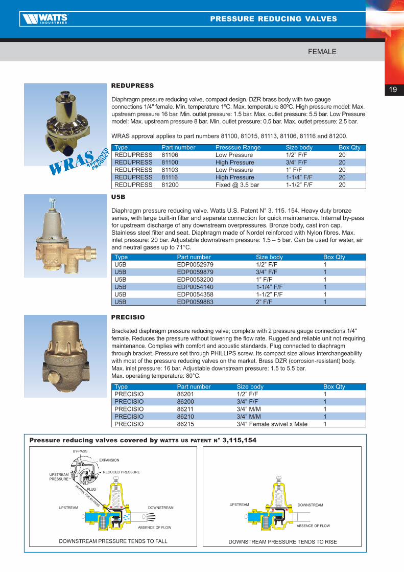
Diaphragm pressure reducing valve. Watts U.S. Patent N° 3. 115. 154. Heavy duty bronzeseries, with large built-in filter and separate connection for quick maintenance. Internal by-passfor upstream discharge of any downstream overpressures. Bronze body, cast iron cap.Stainless steel filter and seat. Diaphragm made of Nordel reinforced with Nylon fibres. Max.inlet pressure: 20 bar. Adjustable downstream pressure: 1.5 – 5 bar. Can be used for water, airand neutral gases up to 71°C.
U5B
Type Part number Size body Box QtyU5B EDP0052979 1/2” F/F 1U5B EDP0059879 3/4” F/F 1U5B EDP0053200 1” F/F 1U5B EDP0054140 1-1/4” F/F 1U5B EDP0054358 1-1/2” F/F 1U5B EDP0059883 2” F/F 1
REDUPRESS
Type Part number Presssue Range Size body Box QtyREDUPRESS 81106 Low Pressure 1/2” F/F 20REDUPRESS 81100 High Pressure 3/4” F/F 20REDUPRESS 81103 Low Pressure 1” F/F 20REDUPRESS 81116 High Pressure 1-1/4” F/F 20REDUPRESS 81200 Fixed @ 3.5 bar 1-1/2” F/F 20
Bracketed diaphragm pressure reducing valve; complete with 2 pressure gauge connections 1/4"female. Reduces the pressure without lowering the flow rate. Rugged and reliable unit not requiring maintenance. Complies with comfort and acoustic standards. Plug connected to diaphragmthrough bracket. Pressure set through PHILLIPS screw. Its compact size allows interchangeabilitywith most of the pressure reducing valves on the market. Brass DZR (corrosion-resistant) body.Max. inlet pressure: 16 bar. Adjustable downstream pressure: 1.5 to 5.5 bar.Max. operating temperature: 80°C.
PRECISIO
Type Part number Size body Box QtyPRECISIO 86201 1/2” F/F 1PRECISIO 86200 3/4” F/F 1PRECISIO 86211 3/4” M/M 1PRECISIO 86210 3/4” M/M 1PRECISIO 86215 3/4" Female swivel x Male 1
DOWNSTREAMUPSTREAM
ABSENCE OF FLOW
DOWNSTREAM PRESSURE TENDS TO FALL DOWNSTREAM PRESSURE TENDS TO RISE
EXPANSION
REDUCED PRESSURE
PLUG
UPSTREAMPRESSURE
BY-PASS
PROTECTIVE BY-PASSDOWNSTREAM UPSTREAM
ABSENCE OF FLOW
Pressure reducing valves covered by WATTS US PATENT N° 3,115,154
Diaphragm pressure reducing valve, compact design. DZR brass body with two gauge connections 1/4" female. Min. temperature 1ºC. Max. temperature 80ºC. High pressure model: Max.upstream pressure 16 bar. Min. outlet pressure: 1.5 bar. Max. outlet pressure: 5.5 bar. Low Pressuremodel: Max. upstream pressure 8 bar. Min. outlet pressure: 0.5 bar. Max. outlet pressure: 2.5 bar.
WRAS approval applies to part numbers 81100, 81015, 81113, 81106, 81116 and 81200.

20
FEMALE
PRESSURE REDUCING VALVES
Pressure reducing valve with highly sensitive spring and large diaphragm that permits accurateadjustment. High temperature diaphragm for both hot and cold water. Bronze body screwedBSP female, stainless steel seat. Max. upstream pressure: 20 bar. Adjustable downstreampressure: 1.5 – 6.0 bar. Min. temperature 1ºC. Max. temperature 70ºC.
Upon request available with Low and High Pressure versions.
SERIES 223
Type Part number Size body Box Qty223 EDP296239 1/2” F/F 1223 EDP296155 3/4” F/F 1223 EDP296603 1” F/F 1223 EDP296865 1-1/4” F/F 1223 EDP296154 1-1/2” F/F 1223 EDP297448 2” F/F 1223 EDP305735 2-1/2” F/F 1223 EDP303646 3” F/F 1
Compact stainless steel pressure reducing valve for deionised water purification, chemicalhandling, high purity, water purification systems and low pressure steam 15 psi (1.0 bar) applications. Rugged investment cast stainless steel body and spring cage, with gauge connection 1/4" female, stainless steel adjusting screw, oversized orifice. End connection 1/2"NPT female. Max. upstream pressure: 28 bar. Min. temperature 0.5ºC. Max. temperature 49ºC.
Upon request available with Viton Seals.
SERIES SS-263AP
Type Part number Outlet presssure range Supplied set at Box QtySS-263AP EDP0335115 1 – 25 psi 10 psi 1SS-263AP EDP335077 3 – 50 psi 15 psi 1SS-263AP EDP335078 10 – 125 psi 25 psi 1SS-263AP EDP0335080 100 – 300 psi 125 psi 1
Miniature pressure reducing valve in corrosion proof acetal plastic, all internal metalcomponents in contact with the fluid are stainless steel. P50 – Multi-purpose pressure regulatorfor general use. P60 – Balanced piston design for applications where constant downstreampressure and accurate flow performance are required. Connections 1/4" BSP female.Max. upstream pressure: 21 bar. Min. temperature 5ºC. Max. temperature 66ºC.
SERIES P50/P60
Type Part number Outlet presssure range Supplied set at Box QtyP50 EDP0354551 0 – 25 psi 15 psi 1P50 EDP0354552 0 – 60 psi 40 psi 1P50 EDP0354553 0 – 125 psi 50 psi 1P60 EDP0354554 0 – 25 psi 15 psi 1P60 EDP354555 0 – 60 psi 40 psi 1P60 EDP354556 0 – 125 psi 50 psi 1P60 4WAY EDP354591 0 – 60 psi 40 psi 1P60 4WAY EDP354592 0 – 125 psi 50 psi 1

21
UNION
PRESSURE REDUCING VALVES
Diaphragm pressure reducing valve with compensated seat and complete with unions.Brass CW617N body and cap. Stainless steel strainer. 1/2" - 3/4" - 1" = 600 µ1 1/4" - 1 1/2" - 2" = 750 µ. Plastic valve seat. Interchangeable filter-regulator unit. Max. inlet pressure: 25 bar. Adjustable downstream pressure: 1.5 - 6 bar. Can be used forwater, air and neutral gases up to 30°C. Pressure drops less than 1.3 bar at characteristic flowrate DIN. Noise < 20 dB – Class 1 in Germany.
DRV
Type Part number Size body Box QtyDRV 0501115 1/2” M/M 10DRV 0501120 3/4” M/M 10DRV 0501125 1” M/M 10DRV 0501132 1 1/4” M/M 1DRV 0501140 1 1/2” M/M 1DRV 0501150 2” M/M 1
Patented diaphragm pressure reducing valve with compensated seat, outlet pressureadjusting knob and external graduated scale for easy reading of set pressure.Complete with unions. Body and cap of shot-blasted stamped brass CW617N.Stainless steel filter cartridge. Pressure gauge connection on both sides: 1/4".Materials in contact with fluids KTW certified. Max. inlet pressure: 25 bar.Adjustable downstream pressure: 1.5 and 6 bar. Max. operating temperature: 30°C. Can be used for water, air and neutral gases. Noise < 20 dB – Class 1 in Germany.
According to DVGW.
DRVN
Type Part number Size body Box QtyDRVN 0502515 1/2” M/M 10DRVN 0502520 3/4” M/M 10DRVN 0502525 1” M/M 10DRVN 0502532 1 1/4” M/M 1DRVN 0502540 1 1/2” M/M 1DRVN 0502550 2” M/M 1
CAVITATIONThe cavitation diagram shows three operating zones of the pressure reducing valveplotted against the upstream and downstream pressures, namely:Zone C: normal duty, no cavitationZone B: medium duty, risk of cavitationZone A: heavy duty, the pressure reducing valve shows cavitation.Continuous operation in the red cavitation zone could cause rapid damage of theinternal parts.SIZINGExample 1 (cavitation)Pressure reducing valve with: Inlet pressure P1 = 14 bar. Outlet pressure P2 = 3 bar.From the cavitation diagram it can be seen that the pressure reducing valve is constantly working in the red zone. To avoid rapid deterioration, two pressure reducing valves could be used, one connected upstream to the other. Upstream pressure reducing valve: pressure front from 14 to 6 bar (green zone). Downstream pressure reducing valve: pressure front from 6 to 3 bar (green zone).
Cavitation diagram for pressure reducing valves seriesDRV
20
A Cavitation zone B Transition zone C Work zone
18
16
14
12
10
8
6
4
2
00 1 2 3
(bar)
(bar)
Downstream pressure
Inle
t pre
ssure
4 5 6 7
A
B
C

22
UNION
PRESSURE REDUCING VALVES
Pressure reducing valve brass body and diaphragm, stainless steel seat, NBR O-rings, twogauge connections 1/4" BSP female. Max. upstream pressure: 20 bar. Adjustable downstreampressure: 0.6 – 6.0 bar. Min. temperature 1ºC. Max. temperature 80ºC.
MOV809T-143
Type Part number Size body Box Qty809T-143 M11200 1/2” F/F 1809T-143 M11201 3/4” F/F 1
Pressure reducing valve brass body and diaphragm, stainless steel seat, NBR O-rings, twogauge connections 1/4" BSP female. Max. upstream pressure: 20 bar. Adjustable downstreampressure: 0.6 – 6.0 bar. Min. temperature 1ºC. Max. temperature 80ºC.
MOV809T-146
Type Part number Size body Box Qty809T-146 M11300 1/2” F/F 1809T-146 M11301 3/4” F/F 1809T-146 M11302 1” F/F 1809T-146 M11303 1-1/4” F/F 1809T-146 M11304 1-1/2" FF 1809T-146 M11305 2" FF 1

23
FLANGED
PRESSURE REDUCING VALVES
PR500
Type Part number Size body PN Box QtyPRV500 500050549 50 10/16 1PRV500 500065549 65 10/16 1PRV500 500080549 80 10/16 1PRV500 500100549 100 10/16 1PRV500 500125549 125 10/16 1PRV500 500150549 150 10/16 1PRV500 500200549 200 10 1PRV500 505200549 200 16 1
The pilot operated reducing valve PR500 reduces a higher upstream pressure to
a constant lower downstream pressure. This very accurate valve is designed to
operate with a minimum of maintenance. The only moving parts in the valve are
the diaphragm and the stem assembly, which are guided by an exchangeable
bearing in the cover and the valve seat. The Watts PR500 is easy to install and
adjust. It is available with flanges (DN50 - DN250).
1
32
5
4
6
10.050 80 125 200 300 400 600
65 100 150 250 350 500
1.0
0.110 100 1000 10000
25.0
20.0
15.0
10.0
5.0
0.00 1 2 3 4 5 6 7
AB
C
A
B
C
Cavitations
Possible cavitations
No cavitations
Q (quantity in m3/h)
Δ P in bar Inlet pressure (bar)
Outlet pressure (bar)
maximum velocity: 4,3 m/s
Pressure Loss Curve Cavitation Curve
DN PN A B1 B2 C1 C2 Kg
50 10/16 230 160 85 165 85 20
65/60 10/16 290 170 85 165 95 25
80 10/16 310 175 85 165 100 30
100 10/16 350 190 120 210 110 40
125 10/16 400 200 150 285 125 70
150 10/16 480 210 150 285 145 90
DN PN A B1 B2 C1 C2 Kg
200 10 600 235 200 360 170 150
200 16 600 235 200 360 170 150
250 10 730 280 255 475 200 400
250 16 730 280 255 475 200 400
C1
C2
B2
A
B1
Dimensions
Max. temperature: 70˚C continuous
WRAS approval applies on sizes up to and including DN250 for above ground applications on
water systems to a maximum 20ºC.
No. Name1 Body/main valve2 Fixed orifice3 Flow strainer4 Pilot valve5 Air vent6 Flexible tubing


Boilercomponents

26
SAFETY VALVES
Like MSL but with 1/2" female connections.
MSV
Type Part number Size body bar Box QtyMSV 0207110 1/2" 1 40MSV 0207115 1/2" 1,5 40MSV 0207525 1/2" 2,5 40MSV 0207530 1/2" 3 40MSV 0207540 1/2" 4 40MSV 0207150 1/2" 5 40MSV 0207160 1/2" 6 40MSV 0207170 1/2" 7 40MSV 0207180 1/2" 8 40MSV 0207190 1/2" 9 40MSV 0207199 1/2" 10 40
Normal type diaphragm safety valve. Brass CW617N body. Plastic manual discharge knob.Ni-Cr steel spring. Operating temperature range: -10°C to 110°C. Also with glycol: 50%. 1/2" M/F connections.
MSL at 3 bar according to UDT and is AFNOR, CSTB approved. According to DirectivePED 97/23/CE. Identification number CE1115.
MSL
Type Part number Size body bar Box QtyMSL 0206115 1/2" 1,5 40MSL 0206525 1/2" 2,5 40MSL 0206530 1/2" 3 40MSL 0206540 1/2" 4 40MSL 0206150 1/2" 5 40MSL 0206160 1/2" 6 40MSL 0206170 1/2" 7 40MSL 0206180 1/2" 8 40MSL 0206190 1/2" 9 40MSL 0206199 1/2" 10 40
Diaphragm safety valve for solar systems. Body of brass CW617N, EN 12165-99.Elastomeric diaphragm. Discharge pressure factory set and with sealed knob. Suitable for water, also water mixtures (glycol up to 50%) as according to DIN 4757 Part 1.Max operating temperature: 160°C.
TÜV SOLAR certified. According to Directive PED 97/23/CEE.Identification number CE1115.
SVE-SOL
Type Part number Size body bar Box QtySVE-SOL 0215835 1/2" x 3/4" 3,5 40SVE-SOL 0215840 1/2" x 3/4" 4 40SVE-SOL 0215860 1/2" x 3/4" 6 40SVE-SOL 0215880 1/2" x 3/4" 8 40SVE-SOL 0215899 1/2" x 3/4" 10 40
NEW
FOR SOLAR SYSTEMS
BOILER COMPONENTS

27
SAFETY VALVES
Normal type diaphragm safety valve. Brass CW617N body. Plastic manual discharge knob.Ni-Cr steel spring. Diaphragm and seals of rubber resistant to 140°C. Female connectionswith reinforced outlet.
TÜV/TSUP approved. According to Directive PED 97/23/CE.Identification number CE1115.
SV
Type Part number Size body bar Box QtySV 0216115 1/2" x 3/4" 1,5 40SV 0215125 1/2" x 3/4" 2,5 40SV 0215130 1/2" x 3/4" 3 40SV 0215104 1/2" x 3/4" 4 40SV 0216105 1/2" x 3/4" 5 40SV 0216106 1/2" x 3/4" 6 40SV 0216107 1/2" x 3/4" 7 40 SV 0216108 1/2" x 3/4" 8 40SV 0216110 1/2" x 3/4" 10 40SV 0217215 3/4" x 1" 1,5 40SV 0217625 3/4" x 1" 2,5 40SV 0217630 3/4" x 1" 3 40SV 0217604 3/4" x 1" 4 40SV 0217205 3/4" x 1" 5 40SV 0217206 3/4" x 1" 6 40SV 0217207 3/4" x 1" 7 40SV 0217208 3/4" x 1" 8 40SV 0217210 3/4" x 1" 10 40SV 0218615 1" x 1 1/4" 1,5 40SV 0218625 1" x 1 1/4" 2,5 40SV 0218630 1" x 1 1/4" 3 40SV 0218604 1" x 1 1/4" 4 40SV 0218305 1" x 1 1/4" 5 40SV 0218606 1" x 1 1/4" 6 40SV 0218607 1" x 1 1/4" 7 40SV 0218608 1" x 1 1/4" 8 40SV 0218610 1" x 1 1/4" 10 40SV 0219615 1" x 1 1/4" 1,5 40SV 0219625 1" x 1 1/4" 2,5 40SV 0219630 1" x 1 1/4" 3 40SV 0219604 1" x 1 1/4" 4 40SV 0219405 1" x 1 1/4" 5 40SV 0219606 1" x 1 1/4" 6 40SV 0219607 1" x 1 1/4" 7 40SV 0219608 1" x 1 1/4" 8 40SV 0219610 1" x 1 1/4" 10 40
Like MSV with BSP connections. Set at 3.0 bar with gauge port. Supplied with and without gauge.
MSM/MSML
BOILER COMPONENTS
Type Part number Size body Box QtyMSML30 C/W GAUGE 0210430 1/2"M x 1/2”F 60MSM30 C/W GAUGE 0210130 1/2"F x 1/2”F 60MSML/E - NO GAUGE 0210530 1/2"F x 1/2”F 100

28
BOILER COMPONENTS
The valve stem is not in brass as other valves on the market, but made of PA6.6 fibreglass and reinforced highresistance polymer.
This synthetic material presentsexceptional mechanical resistance, and it is largely used in water metersand valves.
100% recyclable, PA6.6 is particularlyappreciated by leading-edge industriesfor its endurance, insulation, and totalabsence of corrosion. This ensuresreliable operation even in a corrosiveatmosphere (ie close to the sea) or withan outside installation such as a roof top,and avoids any risk of binding or locking.
Robust and low complexity constructionproviding superior reliability and longevity.
Dezincification resistant brass housing.
The control knob, made of PA6GFinstead of a lever type valve, is moreaesthetic and with a modern design tocomplement the finish of today’s systems.
The pressure relief function is reliable andguaranteed by both European ISO9001production and a wealth of experiencegained in its different world markets.
The diaphragm is in EPDM and forsanitary use. This piece is cast solid andthe brass insert is vulcanized with therubber diaphragm, providing betterreliability and no risk of leakage.
The probe is hung by a innovativeattachment unit.
The probe is accurate and proven.Exclusively designed and manufacturedby Watts Industries.
P&T – PRESSURE AND TEMPERATURE RELIEF VALVES
Installation example
ApprovalWRAS N°1003045
Discharge rating1/2” and 3/4” Ø 15: 10kW3/4” Ø 22: 25kW
PRESSURE AND TEMPERATURE RELIEF VALVES – 684
Technical specificationsPressure opening 3-4-6-7-10 barTemp. opening 92°CMedium Sanitary waterNominal pressure PN 10
Material specificationsBody DZR BrassSpring SteelControl knob PA6 GFDiaphragm EPDM

29
BOILER COMPONENTS
Correct installation
Incorrect installation
PRESSURE AND TEMPERATURE RELIEF VALVES – 684
The combined 2 in 1 P&T relief valve provides the least expensive and provenmeans for protection against both excessive pressure and temperature emergencyconditions. Provides fully automatic pressure and temperature relief protection for hot waterstorage tanks and heaters.
Application
Fully automatic pressure and temperature relief protection for domestic hot watersupply tanks and heaters.
Typical installation
Please refer to local Regulation.
• All recognized codes require that a temperature actuated relief valve be installed on astorage water heater, generally in such a manner that the temperature sensing element is incontact with hot water in the top 6 inches (152mm) of the tank.
• A drain line must be fitted to each P&T valve.
• The drain line should discharge into a floor drain, check to see that a discharge line isconnected to this valve directing the flow of hot water from the valve to a proper place ofdisposal otherwise personal injury may result.
• The drain pipe from the P&T must discharge through a tundish, to a safe and visible positionto alert the householder of a fault condition with the system.
• The P&T relief valves must be installed by qualified technical plumbers in accordance withcurrent regulations.
• The P&T relief valve must be installed observing the direction of flow indicated by the arrowon the valve body.
• The 684 P&T relief valves can be fitted vertically or horizontally, but not inverted.
Features
• These P&T valves feature a unique probe with special thermo-bonded coating.Thermostat is accurate and proven.
• Exclusively designed and manufactured by Watts Industries.
• Temperature nominal setting: 92°C, the valve opens between 89°C and 95°C.
• The European Standard EN 1490: 2000, entitled “Building valves – Combined pressure andtemperature relief valves – Tests and requirements”, describes the constructional andperformance specifications that P&T relief valves must have.
• The Watts Industries series 684 P&T relief valves are certified to comply with therequirements of this European Standard EN 1490 (for settings 4 – 7 – 10 bar).
SELF-CLOSING P&T RELIEF VALVES FOR WATER HEATERS
HOT WATER
STORAGE
HEATER
HOT WATER
STORAGE
HEATER
HOT WATER
STORAGE
HEATER

30
PRESSURE RELIEF VALVES AND COMMERCIAL SAFETY RELIEF VALVES
Fully automatic temperature and pressure relief valve. Protection for domestic installations ofunvented water heaters, to prevent the temperature of water exceeding 100ºC. Pressed DZRbrass body BSP threads. EPDM diaphragm. Temperature setting 92ºC.
WRAS approved, please contact to confirm part number.
P&T – PRESSURE AND TEMPERATURE RELIEF VALVES
Bronze body safety relief valve for all types of hot water boiler equipment with manual lever.Pressure range 30 to 150 psi (2 to 10 bar). Operating temperature range Min. 1ºC Max.140ºC. Bronze body screwed BSP Female. Stainless steel spring. Teflon seat (avoidssticking). EPDM membrane. Available to order – other set pressures.
SERIES 174A SAFETY RELIEF VALVE
Pressure Part number Size body Box Qty3 bar EDP279030 3/4” 17 bar EDP279070 3/4” 13 bar EDP279150 1” 17 bar EDP279190 1” 13 bar EDP279220 1-1/4” 17 bar EDP279250 1-1/4” 13 bar EDP276487 1-1/2” 17 bar EDP276490 1-1/2” 13 bar EDP279320 2” 17 bar EDP279370 2” 1
Water services vacuum relief valve. Automatically vents a closed system if vacuum occurs.Relieves vacuum conditions which would siphon the water from the system and burn out awater heater or collapse a tank.Max. operating pressure: 13.8 bar. Max. operating temperature: 121ºC.Venting capacity 425 litres/min (air).
N36 VACUUM RELIEF VALVE
Type Part number Size body Box QtyN36 EDP138457 1/2" NPT 1N36 EDP0138458 3/4" NPT 1
BOILER COMPONENTS
Setting Part number Size Ø inlet – outlet ND7 bar 68400 M 1/2” – comp.15mm 1/2” 10 bar 68401 M 1/2” – comp.15mm 1/2” 7 bar 68402 Comp.15 mm – comp.15 mm 1/2” 7 bar 68403 M/F 1/2” 1/2” 10 bar 68404 M/F 1/2” 1/2” 3 bar 68450 M/F 3/4” 3/4” 4 bar 68451 M/F 3/4” 3/4” 6 bar 68452 M/F 3/4” 3/4” 7 bar 68453 M/F 3/4” 3/4” 7 bar 68454 M/F 3/4” – 9” probe 3/4” 10 bar 68455 M/F 3/4” 3/4” 7 bar 68456 M 3/4” – comp. 15 mm 3/4” 10 bar 68457 M 3/4” – comp. 15 mm 3/4” 7 bar 68458 M 3/4” – comp. 22 mm 3/4” 10 bar 68459 M 3/4” – comp. 22 mm 3/4”

31
AUTOMATIC FILLING VALVES AND RELIEF VALVES
ALIMATAutomatic filling valve complete with check valve, manual shut-off, stainless steel filter, ventscrew. Brass CW617N body. High impact plastic cap.Pressure gauge connection 1/4" F. Max. upstream pressure: 10 bar.Adjustable downstream pressure: 0.3 to 4 bar.
AL
Type Part number Size body Box QtyAL 0240100 1/2" MF 30
FILLMATICAutomatic filling valve complete with 0-6 bar pressure gauge 3112C, self-cleaning checkvalve, manual shut-off, sintered bronze filter. Brass CW617N body.Max. upstream pressure: 10 bar. Adjustable downstream pressure: 0.3 to 4 bar.Set pressure: 1 bar. Setting ratio: 1 rev. = 0.4 m w.g.
3110C
Type Part number Size body Box Qty3110C 3110C12 1/2" MF 1
Like AL but with pressure gauge MR-RADIAL (50 mm dial, bottom entry, 0 - 4 bar).
ALM
Type Part number Size body Box QtyALM 0240200 1/2" MF 30
Combined filling and backflow preventer unit for boilers up to 45kW.Backflow preventer CA9C. Fillmatic filling valve. Two ball valves and Y type strainer.Connections 1/2” BSP Female.
CA9C FILLING KIT
Type Part number Size body Box QtyCA9C3110C M11801 1/2” 1
3.5
3.53
2
10.3
10 ÷
35
m H
2O
34
5
6
1
2
0.3
3.53
2
10.3
10 m
H2O
34
5
6
1
2
Pressure settingThe filling valve is factory set at a pressure of 1 bar. To adjust for pressures other than the factory setting, merely turn thescrew clockwise to increase the pressure (max. 4 bar) or anti-clockwise todecrease it (min. 0.3 bar).
InstallationInstall the valve according to the direction of the arrow stamped on thevalve body. For quicker filling, make sure the regulating valve is fully open,even if it is advisable to introduce the water at a sufficiently low speed inorder to avoid formation of water pockets which are difficult to expel. Whenfilling, the device ensures that all water supplied from the mains is filtered.
Filling valves
BOILER COMPONENTS

32
DUOVENT (PATENTED)Automatic and manual air vent valve with unscrewable cover for inspection complete withautomatic shut-off valve RIA. Body and cover of brass CW617N. Corrosion-resistantpolyethylene float. Nominal pressure: 12 bar. Max. operating pressure: 8 bar. Max. temperature: 115°C. Automatic venting capacity at 3 bar: 17.9 litres/min. Manual venting capacity at 3 bar: 139.5 litres/min. Also suitable for water containingadditive (glycol up to 30%).
MVDR
Type Part number Size body Box QtyMVDR 0250708 1/4" 120MVDR 0250710 3/8" 120MVDR 0250715 1/2" 120
The ever increasing use of horizontal or single-pipe distributionsystems has led to the engineering of networks with small diameterpiping, without slopes and with closed circuits, thus requiring thedevelopment of a special product line for venting air from thecircuits. Compared to the conventional automatic operation withfloat determined by the water level in the heating system, theDUOVENT air vent valve offers the advantage of manual dischargewhich allows checking for correct operation and cleaning of theautomatic discharge orifice as well as reducing emptying times. For manual discharge, unscrew the red cap and push the disc downwith a screwdriver. When held down, it allows the water to flowthrough the orifice.
The presence of the shut-off valve allows maintenance operationswithout emptying the system.
Advantage of built-in manual discharge
Automatic and manual vent at the various pressures
AUTOMATICDISCHARGEMANUAL
DISCHARGE
SHUT-OFF VALVE
AIR VENTS WITH FLOAT
AIR VENTS

33
AIR VENTS WITH FLOAT
AIR VENTS
MVR
MINIVENTAutomatic air vent valve complete with automatic sealed shut-off valve RIA withunscrewable cover for inspection. Body and cover of brass CW617N. Corrosion-resistantpolyethylene float. Max. pressure: 12 bar. Max. temperature: 115°C. Also suitable for watercontaining additive (glycol up to 30%).
Type Part number Size body Box QtyMVR 0250108 1/4" 10MVR 0250110 3/8" 10MVR 0250115 1/2" 10
MKVR
MICROVENTAutomatic vertical air vent valve complete with automatic sealed shut-off valve RIA. Bodyand cover of brass CW617N. Sealed with O-Ring. Max. pressure: 10 bar. Max. temperature:110°C. Also suitable for water containing additive (glycol up to 30%).
Type Part number Size body Box QtyMKVR 0251310 3/8" 10
MKLR
MICROVENTAutomatic side air vent valve complete with automatic sealed shut-off valve RIA. Body andcover of brass CW617N. Sealed with O-Ring. Max. pressure: 10 bar. Max. temperature:110°C. Also suitable for water containing additive (glycol up to 30%).
Type Part number Size body Box QtyMKLR 0252310 3/8" 10MKL 0252410 1/2” 10
INTERVENTAutomatic vertical air vent valve complete with automatic shut-off valve RIA.Body and cover of brass CW617N.Max. pressure: 10 bar. Max. temperature: 115°C.
INTR
Type Part number Size body Box QtyINT 0252110 3/8" 10INT 0252115 1/2" 10
34
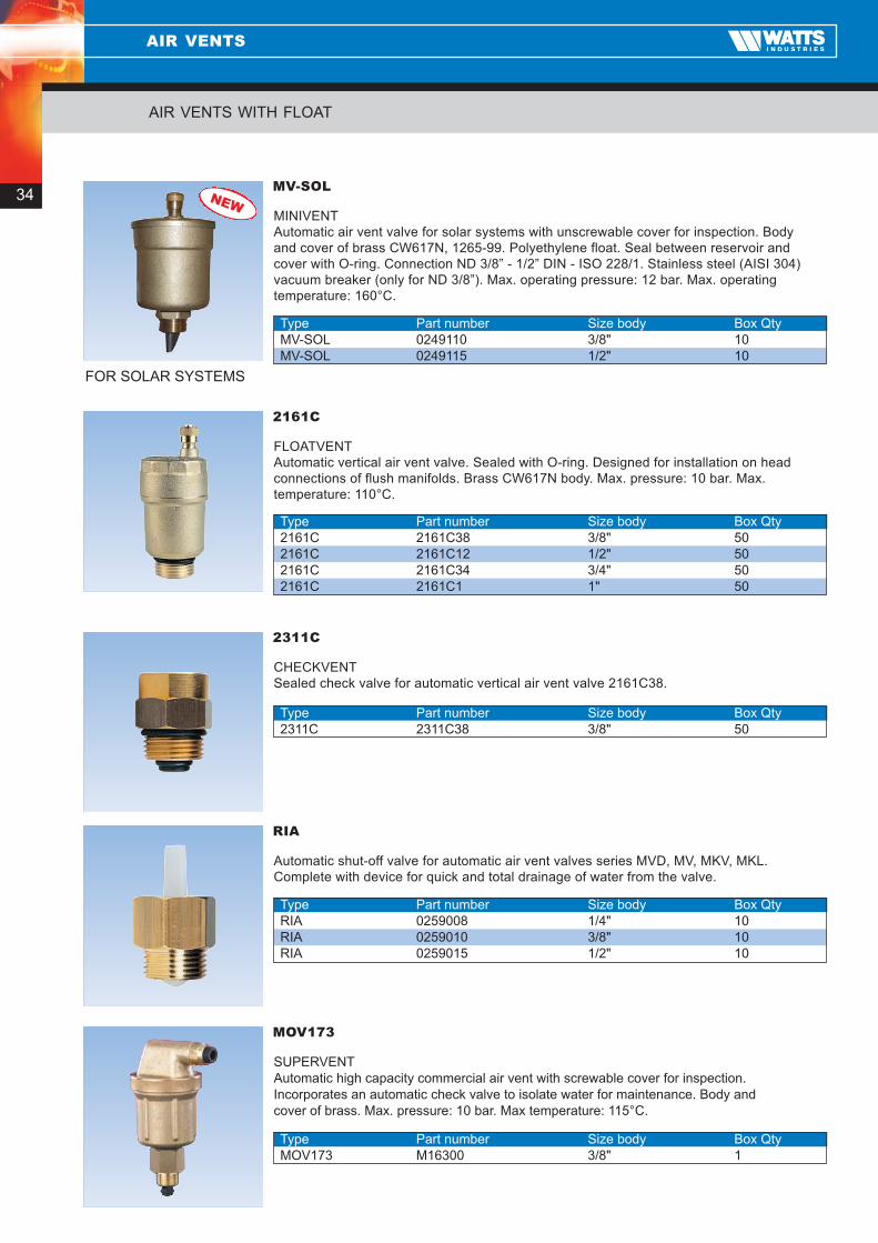
MINIVENTAutomatic air vent valve for solar systems with unscrewable cover for inspection. Body and cover of brass CW617N, 1265-99. Polyethylene float. Seal between reservoir and cover with O-ring. Connection ND 3/8” - 1/2” DIN - ISO 228/1. Stainless steel (AISI 304)vacuum breaker (only for ND 3/8”). Max. operating pressure: 12 bar. Max. operatingtemperature: 160°C.
MV-SOL
Type Part number Size body Box QtyMV-SOL 0249110 3/8" 10MV-SOL 0249115 1/2" 10
FLOATVENTAutomatic vertical air vent valve. Sealed with O-ring. Designed for installation on headconnections of flush manifolds. Brass CW617N body. Max. pressure: 10 bar. Max.temperature: 110°C.
2161C
Type Part number Size body Box Qty2161C 2161C38 3/8" 502161C 2161C12 1/2" 502161C 2161C34 3/4" 502161C 2161C1 1" 50
NEW
FOR SOLAR SYSTEMS
Automatic shut-off valve for automatic air vent valves series MVD, MV, MKV, MKL.Complete with device for quick and total drainage of water from the valve.
RIA
Type Part number Size body Box QtyRIA 0259008 1/4" 10RIA 0259010 3/8" 10RIA 0259015 1/2" 10
CHECKVENTSealed check valve for automatic vertical air vent valve 2161C38.
2311C
Type Part number Size body Box Qty2311C 2311C38 3/8" 50
SUPERVENTAutomatic high capacity commercial air vent with screwable cover for inspection. Incorporates an automatic check valve to isolate water for maintenance. Body and cover of brass. Max. pressure: 10 bar. Max temperature: 115°C.
MOV173
Type Part number Size body Box QtyMOV173 M16300 3/8" 1
AIR VENTS WITH FLOAT
AIR VENTS

35
MANUAL AIR VENT VALVES
AIR VENTS
Manual air vent valve for radiators, with adjustable discharge nozzle. Manual dischargeopening through screwdriver or coin. Chrome-plated brass body CW617N. Glass fibrereinforced nylon handwheel and discharge nozzle body. Sealed on radiator through O-ring. Max. operating pressure: 10 bar.
VMM
Type Part number Size body Box QtyVMM 0256206 1/8" 100VMM 0256208 1/4" 100VMM 0256210 3/8" 100
Manual air vent valve
Manual air vent valve for radiators, with adjustable discharge nozzle. Manual vent openingthrough screwdriver, coin. Chrome-plated brass body CW617N. Glass fibre reinforced nylondischarge nozzle. Sealed on radiator through O-ring. Max. pressure: 10 bar.
PMC
Type Part number Size body Box QtyPMC 0256306 1/8" 100PMC 0256308 1/4" 100PMC 0256310 3/8" 100PMC 0256315 1/2" 100
Drain valve for radiators. Chrome-plated brass body. Adjustable plastic discharge nozzle.Sealed on radiator through O-ring.
RSR
Manual air vent valve for radiators, with adjustable discharge nozzle. Knurled handwheel.Chrome-plated brass CW617N body and discharge nozzle. Sealed on radiator through O-ring. Max. pressure: 10 bar.
SMM
Type Part number Size body Box QtySMM 0257106 1/8" 100SMM 0257108 1/4" 100SMM 0257110 3/8" 100SMM 0257115 1/2" 100
VMM PMC CH
Inlet hole smaller thanthe outlet hole to avoidinfiltration of particleswhich could block airdischarge.
Valve handwheel PMC with opening by screwdriver or coin.
Insert for adjusting discharge nozzle body.Wrench CH can be leftinserted on the body.
Adjustable dischargenozzle, glass fibrereinforced nylonbody.
O-ring for easyassembly and perfectly tight seal on the radiator.
Handwheel designedfor manual openingwith screwdriver or coin. Limit stop onthe screw to avoidthe handwheel coming out from thevalve body.
Insert for openingvalves PMC, RSR
Insert for openingvalve VMM
Type Part number Size body Box QtyRSR 0256008 1/4" 100RSR 0256010 3/8" 100RSR 0256015 1/2" 100

36
THERMOMETERS, PRESSURE GAUGES, METERING PIPES AND ACCESSORIES
Pressure gauge complete with reference needle. Dial diameter: 50 mm.1/4" M axial connection.
According to ISPESL.
Type Part number Scale Box QtyMA50/4 0310104 0-4 bar 10MA50/6 0310106 0-6 bar 10MA50/10 0310110 0-10 bar 10MA50/16 0310116 0-16 bar 10
Pressure gauge complete with reference needle. Dial diameter: 50 mm.1/4" M radial connection.
According to ISPESL.
MR-RADIAL
Type Part number Scale Box QtyMR50/4 0312104 0-4 bar 10MR50/6 0312106 0-6 bar 10MR50/10 0312110 0-10 bar 10MR50/16 0312116 0-16 bar 10
MA-AXIAL
Thermometer/pressure gauge with ABS case, complete with sheath and shut-off valve.Dial diameter: 80 mm. 1/2" M axial connection. Temperature scale: 0° - 120°C.
According to ISPESL.
TMAX
Type Part number Scale Box QtyTMAX/2 0332002 0-2,5 bar 10TMAX/4 0332004 0-4 bar 10TMAX/6 0332006 0-6 bar 10
Thermometer/pressure gauge with ABS case, complete with sheath and shut-off valve.Dial diameter: 80 mm. 1/2" M radial connection. Temperature scale: 0° - 120°C.
According to ISPESL.
TMRA
Type Part number Scale Box QtyTMRA/2 0333002 0-2,5 bar 10TMRA/4 0333004 0-4 bar 10TMRA/6 0333006 0-6 bar 10
BOILER COMPONENTS

37
THERMOMETERS, PRESSURE GAUGES , METERING PIPES AND ACCESSORIES
Contact thermometer with bimetallic helix element. Complete with steel sheet spring forholding on pipe. Black painted steel case. Chrome-plated rim. Scale divisions 1°C.
TB
Type Part number Scale Face Box QtyTB 0308060 0-120 °C 63 mm 10
Pressure gauge complete with reference needle. Dial diameter: 60 mm.1/4"M axial connection.
According to ISPESL.
MA60-AXIAL
Type Part number Scale Box QtyMA60-AXIAL 0316204 0-4 bar 10MA60-AXIAL 0316206 0-6 bar 10MA60-AXIAL 0316210 0-10 bar 10MA60-AXIAL 0316216 0-16 bar 10
Pressure gauge complete with reference needle. Dial diameter: 60 mm.1/4" male radial connection.
According to ISPESL.
MA60-RADIAL
Type Part number Scale Box QtyMA60-AXIAL 0318204 0-4 bar 10MA60-AXIAL 0318206 0-6 bar 10MA60-AXIAL 0318210 0-10 bar 10MA60-AXIAL 0318216 0-16 bar 10
Spare pressure gauge, 0 to 6 bar, for FILLMATIC.
3112C
Type Part number Scale Size body Box Qty3112C 3112C 0-6 bar 1/4" 1
BOILER COMPONENTS


Expansionvessels

40
EXPANSION VESSELS
EXPANSION VESSELS FOR HEATING SYSTEMS
Elements necessary for the calculation of the proper heating systems:• expansion coefficient of water 0,029• initial pressure = static height of the plant• final pressure: 3 barSelection can also be based on the system heating capacity (calculation based on 12 litres of water per 1 kW).
SELECTION CHART
Tanks Volume Precharge Max. plant Average time 80 °C (90-10) Dimensions Connectorcapacity utilised pressure Height Water Maximum power boiler Ø Hlitres litres bar m instal. Ltr KW Kcal/h5 3.1 0.5 5 107 8908 7660 160 320 ¾”
2.5 1 10 86 7183 61771.9 1.5 15 65 5400 4640
8 5 0.5 5 172 14330 12320 200 330 ¾”4 1 10 138 11500 98903 1.5 15 103 8580 7380
12 7.5 0.5 5 259 21580 18560 270 300 ¾”6 1 10 207 17250 148404.5 1.5 15 155 12910 11100
18 11.3 0.5 5 380 32500 27950 270 420 ¾”9 1 10 310 25830 222106.7 1.5 15 231 19250 16580
25 15.6 0.5 5 538 44830 38550 290 450 ¾”12.5 1 10 431 35920 308909.4 1.5 15 324 27000 23220
40 25 0.5 5 862 71800 61750 320 560 ¾”20 1 10 690 57500 4950015 1.5 15 517 43000 37000
35 22 0.5 5 754 62859 54059 380 380 ¾”18 1 10 603 50287 4324713 1.5 15 453 37716 32435
50 31 0.5 5 1078 89799 77227 380 380 ¾”25 1 10 862 71839 6178219 1.5 15 647 53879 46336
80 50 0.5 5 1724 143678 123563 450 450 ¾”40 1 10 1379 114943 9885130 1.5 15 1034 86207 74138
100 63 0.5 5 2155 179598 154454 450 450 ¾”50 1 10 1724 143678 12356338 1.5 15 1293 107759 92672
60 37.5 0.5 5 1293 107758 92670 380 690 ¾”30 1 10 1034 86206 7413522.5 1.5 15 775 64655 55600
80 50 0.5 5 1724 143700 123600 450 680 ¾”40 1 10 1379 115000 9890030 1.5 15 1034 86100 7400020 2 20 690 57500 49500
100 62.5 0.5 5 2155 179600 154500 450 760 1”50 1 10 1724 143700 12360037.5 1.5 15 1293 107700 9260025 2 20 862 71800 61750
150 93.8 0.5 5 3234 269500 231770 550 785 1½”79 1 10 2500 215500 18533056.3 1.5 15 1941 161750 13911037.5 2 20 1293 107750 92670
200 125 0.5 5 4310 358170 308886 550 1010 1½”100 1 10 3448 287330 24710075 1.5 15 2586 215500 18523050 2 20 1724 143570 123560
250 156 0.5 5 5379 448000 358000 630 1000 1½”125 1 10 4310 359000 30800094 1.5 15 3241 270000 23200063 2 20 2172 181000 135000
300 187.5 0.5 5 6468 538830 463400 630 1180 1½”150 1 10 5172 431000 370600112.5 1.5 15 3879 323250 27800075 2 20 2586 216500 186330
500 312.5 0.5 5 10776 898000 773000 780 1260 1½”250 1 10 8621 718000 617000187.5 1.5 15 6466 539000 463000125 2 20 4310 359000 30900062.5 2.5 25 2155 180000 155000
700 437.5 0.5 5 15086 1260000 1084000 780 1620 1½”350 1 10 12069 1005000 864000262.5 1.5 15 9052 754000 648000175 2 20 6034 503000 43200087.5 2.5 25 3017 251000 216000

41
EXPANSION VESSELS
EXPANSION VESSELS FOR HEATING SYSTEMS
Expansion vessel with fixed membrane for central heating and boiler systems. Carbon steel body with red epoxy polyester paint finish, carbon steel flange.Max. system temperature – 99ºC.Max. pressure of vessel – 5 bar.Connection – ¾”Precharged to 1.5 bar.
Part Number Capacity litre Height mm Diameter mmVEX5 5 320 160VEX8 8 330 200VEX12 12 315 270VEX18 18 420 270VEX25 25 450 290VEX40 40 582 320
EXTRAVAREM LR
Expansion vessel with feet and diaphragm membrane for central heating and boiler systems. Carbon steel body with red epoxy polyester paint finish, carbon steel flange.Max. system temperature – 99ºC.Max. pressure of vessel – 6 bar.Connection – ¾”Precharged to 1.5 bar.
Part Number Capacity litre Height mm Diameter mmVST35F 35 392 380VST50F 50 485 380VST80F 80 692 450VST100F 100 763 450
STARVAREM LR
Expansion vessel with replaceable membrane for central heating and boiler systems. Carbon steel body with red epoxy polyester paint finish, carbon steel flange.Max. system temperature – 99ºC.Max. pressure of vessel – 6 bar.Connection – 60-100 Ltr 1” Larger Sizes 1½”Precharged to 1.5 bar.
Part Number Capacity litre Height mm Diameter mmVMA60 60 550 380VMA80 80 735 450VMA100 100 790 450VMA150 150 800 550VMA200 200 1080 550VMA250 250 984 630VMA300 300 1177 630VMA400 400 1540 630VMA500 500 1283 780VMA600 600 1340 780VMA700 700 1685 780
MAXIVAREM LR

42
EXPANSION VESSELS
EXPANSION VESSELS FOR HEATING SYSTEMS
Expansion vessel with fixed membrane for domestic hot water systems. Carbon steel body with white epoxy polyester paint finish, stainless steel flange.Max. system temperature – 99ºC.Max. pressure of vessel – 2 litre 10 bar all others 8 bar.Connection – 2 litre – ½” all other sizes ¾” Precharged to 3.5 bar.
Part Number Capacity litre Height mm Diameter mmVEXP016 0.16 105 65VEXP2 2 240 125VEXP5 5 300 160VEXP8 8 330 200VEXP12 12 315 270VEXP18 18 420 270VEXP24 24 335 360VEXP25 25 450 290
EXTRAVAREM LC WITH STAINLESS STEEL FLANGE
Expansion vessel with replaceable membrane for potable water. Carbon steel body with blue epoxy polyester paint finish, carbon steel flange.Max. system temperature – 99ºC.Max. pressure of vessel – 8 bar.Connection – 1” Precharged to 2.0 bar.
Part Number Capacity litre Height mm Diameter mmVINP5 5 320 160VINP8 8 330 200VINP12 12 315 270VINP19 19 420 270VINP24 24 335 360VINP40 40 582 320
INTERVAREM – POTABLE
Expansion vessel with replaceable membrane for potable water. Carbon steel body with blue epoxy polyester paint finish, stainless steel flange.Max. system temperature – 99ºC.Max. pressure of vessel – 8 bar.Connection – ¾” Precharged to 3.5 bar.
Part Number Capacity litre Height mm Diameter mmVINP5SS 5 329 163VINP8SS 8 330 200VINP12SS 12 315 270VINP19SS 19 420 270VINP20HSS 20 492 290VINP24VSS 24 335 360VINP40SS 40 582 320VINP50SS 50 604 379
INTERVAREM – POTABLE WITH STAINLESS STEEL FLANGE

43
EXPANSION VESSELS
EXPANSION VESSELS FOR HEATING SYSTEMS
Horizontal expansion vessel with replaceable membrane for potable waterCarbon steel body with blue epoxy polyester paint finish, carbon steel flange.Max. system temperature – 99ºC.Max. pressure of vessel – 10 bar.Connection – 60-100 Ltr 1” Larger Sizes 1½”Precharged to 2.0 bar.
Part Number Capacity litre Height mm Diameter mmVMAP40H 40 580 345VMAP50H 50 615 430VMAP60H 60 680 382VMAP80H 80 680 450VMAP100H 100 780 450VMAP200H 200 1030 550VMAP300H 300 1185 630
MAXIVAREM LS HORIZONTAL – POTABLE
Horizontal expansion vessel with replaceable membrane for potable waterCarbon steel body with blue epoxy polyester paint finish, stainless steel flange.Max. system temperature – 99ºC.Max. pressure of vessel – 10 bar.Connection – 60-100 Ltr 1” Larger Sizes 1½”Precharged to 2.0 bar.
Part Number Capacity litre Height mm Diameter mmVMAP40HSS 40 580 345VMAP50HSS 50 615 430VMAP60HSS 60 680 382VMAP80HSS 80 680 450VMAP100HSS 100 780 450VMAP200HSS 200 1030 550VMAP300HSS 300 1185 630
MAXIVAREM LS HORIZONTAL – POTABLE WITH STAINLESS STEEL FLANGE
Vertical expansion vessel with replaceable membrane for potable waterCarbon steel body with blue epoxy polyester paint finish, stainless steel flange.Max. system temperature – 99ºC.Max. pressure of vessel – 10 bar.Connection – 60-100 Ltr 1” Up to 400 Ltr 1½” Precharged to 2.0 bar.
Part Number Capacity litre Height mm Diameter mmVMAP60 60 550 380VMAP80 80 735 450VMAP100 100 790 451VMAP150 150 800 550VMAP200 200 1080 550VMAP250 250 984 630VMAP300 300 1177 630VMAP400 400 1540 630
MAXIVAREM LC VERTICAL – POTABLE

44
EXPANSION VESSELS
EXPANSION VESSELS FOR HEATING SYSTEMS
Vertical expansion vessel with replaceable membrane for potable waterCarbon steel body with blue epoxy polyester paint finish, stainless steel flange.Max. system temperature – 99ºC.Max. pressure of vessel – 10 bar.Connection – 60-100 Ltr 1” up to 750 Ltr 1½” 1000 Ltr – 2”Precharged to 2.0 bar.
Part Number Capacity litre Height mm Diameter mmVMAP50VSS 50 770 382VMAP60VSS 60 845 382VMAP80VSS 80 851 450VMAP100VSS 100 950 450VMAP200VSS 200 1255 550VMAP300VSS 300 1405 630VMAP500VSS 500 1550 780VMAP750VSS 750 1940 780VMAP1000VSS 1000 2200 980
MAXIVAREM LS VERTICAL – POTABLE WITH STAINLESS STEEL FLANGE
Expansion vessel with replaceable membrane for solar energy systems. Carbon steel body with red epoxy polyester paint finish, stainless steel flange.Max. system temperature – 99ºC.Max. pressure of vessel – up to 40 litre – 8 bar larger sizes 6 bar.Connection – 5 - 80 Ltr ¾” 100 Ltr 1” 200 & 300 Ltr 1½”Precharged to 2.5 bar.
Part Number Capacity litre Height mm Diameter mmVSOL5W 5 315 160VSOL8W 8 330 200VSOL12W 12 300 270VSOL19W 19 405 270VSOL25W 25 450 290VSOL40W 40 560 320VSOL60 60 730 380VSOL80 80 735 450VSOL100 100 790 450VSOL200 200 1080 550VSOL300 300 1177 630
SOLARVAREM LR – SOLAR WITH STAINLESS STEEL FLANGE
FLATVAREM – FOR HEATING SYSTEMS – AVAILABLE ON REQUEST

45
EXPANSION VESSELS
EXPANSION VESSELS FOR HEATING SYSTEMS
For installation in central heating and boiler systems.Each kit includes a heating vessel, pressure relief valve with gauge, manifold, mountingbracket (options below available) and combined filling loop, isolator and double check valve.
Part Number Capacity litre Description Box QtySSC5 5 Sealed system filing kit 1SSC8 8 Sealed system filing kit 1SSC12 12 Sealed system filing kit 1SSC18 18 Sealed system filing kit 1SSC24 24 Sealed system filing kit 1
SEALED SYSTEM KIT
Includes bracket, nuts and screws.
Part Number Description Box QtyBRKT1 Mounting kit for vessels 4 to 25 litre 1BRKT2 Mounting kit for o vessels 35 & 50 litre 1
MOUNTING KIT
Wrap round bracket comprising strap, wall bracket and fixing screws.
Part Number Description Box QtyER24KIT Mounting kit for vessels 1V5O920 Mounting kit for vessels 1
MOUNTING KIT
Plain brass manifold cross with 15mm compression inlet, 3/4” BSP Female vessel connection,1/2” BSP male relief valve connection, plain end for connection to double check valve with15mm compression ends.
Part Number Description Box QtyCORE641002 Four way manifold cross 1
MANIFOLD CROSS
SPARE BLADDERS – AVAILABLE ON REQUEST

Balancing valves

48
Regulation of heating, ventilation and air-conditioning systems. Balancing of drinking watercirculation pipes as well as solar and heat pump systems. Excess or insufficient feed to consumercircuits in HVAC systems is the main cause of malfunctions. WattFlow balancing valves take careof hydraulic balancing; they are also easy to operate and require no special training. WattFlowbalancing valves can therefore be used to regulate HVAC systems quickly and with maximumprecision without the need for expensive measuring computers or special tools.
The VOB/C – DIN 18380 standard requires the hydraulic balancing of pipelines, as does DINEN 12828. The pipe systems must be designed in such a way that heating water is fed to allparts of the heating system with the necessary heating energy. The following factors (amongothers) must be taken into account: temperature, operating pressure, pressure loss and noiselevels (due to flow speed, for example). Hydraulically correctly balanced systems can beregulated with greater precision and therefore save both energy and money.
APPLICATIONS OF WATTFLOW BP
All WattFlow BP balancing valves are equipped as standard with an integrated flowmeterwhich continuously measures the current flow volume and indicates it on a scale protrudingfrom the side of the housing. The scale is graduated in l/min and can be rotated about its ownaxis, thereby allowing optimum positioning for convenient and accurate read-off of values. Thedisplay is located away from the flow measurement zone to protect it against dirt and debris.In other words, the medium does not flow directly past the sight glass. The inclinedseat valve with regulating cone (also integrated) regulates the flow volume. The selectedvalve characteristic ensures that the valve stroke is spread across several rotations of thespindle. This guarantees maximum setting accuracy. The flow-friendly valve design ensuresminimum noise emissions. The WattFlow balancing valves are not affected by the flow profileat the inlet, and a straight inlet route of the same length as the housing is therefore generallyadequate. The valves can be mounted in any desired orientation, and the correct direction offlow is indicated by an arrow on the housing.
DESIGN/MODE OF OPERATION
TENDER TEXT FOR WATTFLOW BP
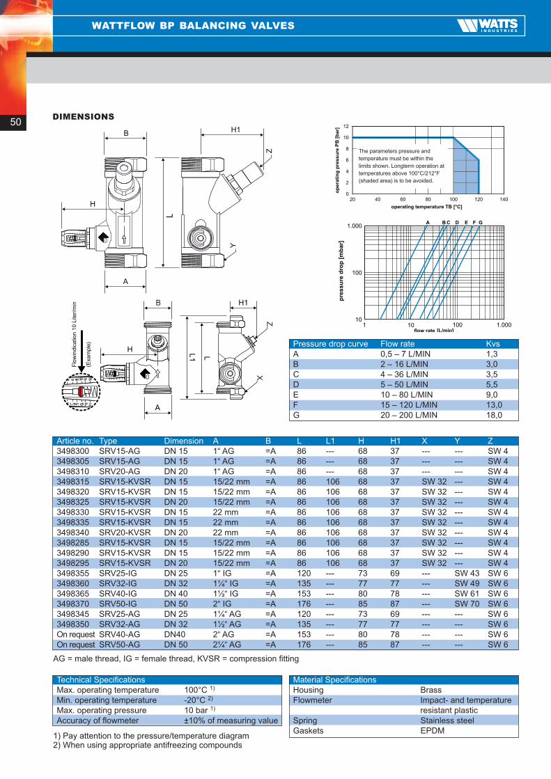
Balancing valve for rapid and exact balancing of consumer circuits in HVAC systems and drinking water circulation pipelines.Integrated flow display with rotatable indicator scale marked in l/min. Actual flow volume can be read off directly without theneed for measuring computers or charts. The sight glass of the flow indicator is not installed directly in the medium flow andis therefore protected against soiling. Measuring accuracy ± 10% of measuring value. The flow volume is adjusted viaseveral spindle rotations of an angle seat valve. Installation orientation as desired in the flow or return lines. Nominal widthDN ..., housing made of brass. Sight glass made of impact- and temperature-resistant plastic. Spring made of stainlesssteel. Gaskets made of EPDM. Max. operating temperature TB 100° C at max. operating pressure PB 10 bar.
Article-no. Type Dimension Connection Flow rate Kvs MemoStop3498300 SRV15-AG DN 15 1“ AG 0,5 – 7 l/min 1,5 without3498305 SRV15-AG DN 15 1“ AG 2 – 16 l/min 3,0 without3498310 SRV20-AG DN 20 1“ AG 4 – 36 l/min 3,5 without3498315 SRV15-KVSR DN 15 KVSR 15 mm 0,5 – 7 l/min 1,5 without3498320 SRV15-KVSR DN 15 KVSR 15 mm 2 – 16 l/min 3,0 without3498325 SRV15-KVSR DN 20 KVSR 15 mm 4 – 36 l/min 3,5 without3498330 SRV15-KVSR DN 15 KVSR 22 mm 0,5 – 7 l/min 1,5 without3498335 SRV15-KVSR DN 15 KVSR 22 mm 2 – 16 l/min 3,0 without3498340 SRV20-KVSR DN 20 KVSR 22 mm 4 – 36 l/min 3,5 without3498285 SRV15-KVSR DN 15 KVSR 15/22 mm 0,5 – 7 l/min 1,5 without3498290 SRV15-KVSR DN 15 KVSR 15/22 mm 2 – 16 l/min 3,0 without3498295 SRV15-KVSR DN 20 KVSR 15/22 mm 4 – 36 l/min 3,5 without3498355 SRV25-IG DN 25 1“ IG 5 – 50 l/min 5,5 with3498360 SRV32-IG DN 32 1 ¼“ IG 10 – 80 l/min 9,0 with3498365 SRV40-IG DN 40 1 ½“ IG 15 – 120 l/min 13,0 with3498370 SRV50-IG DN 50 2“ IG 20 – 200 l/min 18,0 with3498345 SRV25-AG DN 25 1 ¼“ AG 5 – 50 l/min 5,5 with3498350 SRV32-AG DN 32 1 ½“ AG 10 – 80 l/min 9,0 withon request SRV40-AG DN 40 2“ AG 15 – 120 l/min 13,0 withon request SRV50-AG DN 50 2 ¼“ AG 20 – 200 l/min 18,0 with
WATTFLOW BP BALANCING VALVES

49
WATTFLOW OL BALANCING VALVES
Regulation of consumer circuits in heating, ventilation and air-conditioning systems. Balancing ofdrinking water circulation pipes. Excess or insufficient feed to consumer circuits in HVAC systemsis not seldom the cause of malfunctions. WattFlow OL balancing valves were developed toprovide planners and operators with an extremely simple, cost-efficient and effective means ofregulating consumer circuits in heating and cooling systems. WattFlow OL balancing valves canbe used to regulate HVAC systems rapidly and with maximum precision without the need fortraining of personnel.
Hydraulically correctly balanced systems can be regulated with greater precision and thereforesave both energy and money.
APPLICATIONS OF WATTFLOW OL
All WattFlow OL balancing valves are equipped with an integrated flowmeter which continuouslydisplays the current flow volume in litres/min. The advantages of the flow indicator mountedoutside the housing axis are as follows:• As the flow indicator is not positioned directly in the medium flow, the display is protected
against dirt and stays clearly visible for long periods. • The scale element graduated in litres/min can be rotated about its own axis, thereby allowing
convenient read-off of the indicated volume flow in any mounting orientation. • WattFlow OL balancing valves and their flow indicators do not require any special inlet route.
The length of the straight pipe may also be lower than the recommended straight pipe length(equal to the housing length).
• The valves can be mounted in any desired orientation; the correct direction of flow isindicated by an arrow on the housing.
DESIGN/MODE OF OPERATION
TENDER TEXT FOR WATTFLOW OL
WattFlow OL balancing valve with inclined seat valve for rapid and exact hydraulic balancing of consumer circuits in HVACsystems. Balancing valve with integrated flow indicator which is not installed directly in the medium flow and is thereforeprotected against soiling. Flow indicator with rotatable indicator scale. Nominal width DN ..., max. operating temperature100°C at an operating pressure of 6 bar or 70°C at 10 bar. Housing made of brass. Flow indicator made of impact- and heat-resistant plastic. Spring made of stainless steel. Gaskets made of EPDM.
Article no. Type Dimension Connection Flow rate Kvs 3498000 SRVOL15-AG DN 15 ¾“ AG* 1 – 8 l/min 1,7On request SRVOL15-IGAG DN 15 ½“ IG x ¾“ AG* 1 – 8 l/min 1,73498010 SRVOL15-IG DN 15 ½“ IG 1 – 8 l/min 1,73498011 SRVOL20-KVSR DN 20 15 mm 1 – 8 l/min 1,73498012 SRVOL20-KVSR DN 20 22 mm 1 – 8 l/min 1,73498013 SRVOL20-KVSR DN 20 15/22 mm 1 – 8 l/min 1,73498015 SRVOL20-AG DN 20 1“ AG 2 – 16 l/min 2,03498020 SRVOL20-IG DN 20 ¾“ IG 2 – 16 l/min 2,03498025 SRVOL20-KVSR DN 20 15 mm 2 – 16 l/min 2,03498030 SRVOL20-KVSR DN 20 22 mm 2 – 16 l/min 2,03498035 SRVOL20-KVSR DN 20 15/22 mm 2 – 16 l/min 2,0
*eurocone, AG = male thread, IG = female thread, KVSR = compression fitting
50
WATTFLOW BP BALANCING VALVES
0
2
4
6
8
01
21
04102100108060402
op
erat
ing
pre
ssu
re P
B [
bar
]
operating temperature TB [°C]
The parameters pressure and temperature must be within the limits shown. Long-therm operation at temperatures above 100° C/212° F (shaded area) is to be avoided.
01
001
000.1
000.1001011]nim/L[
A B C D E F G
pre
ssu
re d
rop
[m
bar
]
flow rate
Z
Y
B
ZX
B
Flo
win
dica
tion
10 L
iter/
min
(Exa
mpl
e)
AG = male thread, IG = female thread, KVSR = compression fitting
1) Pay attention to the pressure/temperature diagram2) When using appropriate antifreezing compounds
Article no. Type Dimension A B L L1 H H1 X Y Z3498300 SRV15-AG DN 15 1“ AG =A 86 --- 68 37 --- --- SW 43498305 SRV15-AG DN 15 1“ AG =A 86 --- 68 37 --- --- SW 43498310 SRV20-AG DN 20 1“ AG =A 86 --- 68 37 --- --- SW 43498315 SRV15-KVSR DN 15 15/22 mm =A 86 106 68 37 SW 32 --- SW 43498320 SRV15-KVSR DN 15 15/22 mm =A 86 106 68 37 SW 32 --- SW 43498325 SRV15-KVSR DN 20 15/22 mm =A 86 106 68 37 SW 32 --- SW 43498330 SRV15-KVSR DN 15 22 mm =A 86 106 68 37 SW 32 --- SW 43498335 SRV15-KVSR DN 15 22 mm =A 86 106 68 37 SW 32 --- SW 43498340 SRV20-KVSR DN 20 22 mm =A 86 106 68 37 SW 32 --- SW 43498285 SRV15-KVSR DN 15 15/22 mm =A 86 106 68 37 SW 32 --- SW 43498290 SRV15-KVSR DN 15 15/22 mm =A 86 106 68 37 SW 32 --- SW 43498295 SRV15-KVSR DN 20 15/22 mm =A 86 106 68 37 SW 32 --- SW 43498355 SRV25-IG DN 25 1“ IG =A 120 --- 73 69 --- SW 43 SW 63498360 SRV32-IG DN 32 1¼“ IG =A 135 --- 77 77 --- SW 49 SW 63498365 SRV40-IG DN 40 1½“ IG =A 153 --- 80 78 --- SW 61 SW 63498370 SRV50-IG DN 50 2“ IG =A 176 --- 85 87 --- SW 70 SW 63498345 SRV25-AG DN 25 1¼“ AG =A 120 --- 73 69 --- --- SW 63498350 SRV32-AG DN 32 1½“ AG =A 135 --- 77 77 --- --- SW 6On request SRV40-AG DN40 2“ AG =A 153 --- 80 78 --- --- SW 6On request SRV50-AG DN 50 2¼“ AG =A 176 --- 85 87 --- --- SW 6
Pressure drop curve Flow rate KvsA 0,5 – 7 L/MIN 1,3B 2 – 16 L/MIN 3,0C 4 – 36 L/MIN 3,5D 5 – 50 L/MIN 5,5E 10 – 80 L/MIN 9,0F 15 – 120 L/MIN 13,0G 20 – 200 L/MIN 18,0
Technical SpecificationsMax. operating temperature 100°C 1)
Min. operating temperature -20°C 2)
Max. operating pressure 10 bar 1)
Accuracy of flowmeter ±10% of measuring value
Material SpecificationsHousing BrassFlowmeter Impact- and temperature
resistant plasticSpring Stainless steelGaskets EPDM
DIMENSIONS
The parameters pressure and
temperature must be within the
limits shown. Longterm operation at
temperatures above 100°C/212°F
(shaded area) is to be avoided.

51
WATTFLOW OL BALANCING VALVES
0
2
4
6
8
01
21
02100108060402
Pressure/temperature diagram
op
erat
ing
pre
ssu
re P
B [
bar
]
01
001
000.1
001011]nim/l[
BA
pre
ssu
re d
rop
[m
bar
]
Pressure drop diagram
flow rate
X Y
*eurocone, AG = male thread, IG = female thread, KVSR = compression fitting
Subject to technical modifications
1) Pay attention to the pressure/temperature diagram2) When using appropriate antifreezing compounds3) Valid for Water-Glycol above 20°C
Article no. Type Dimension A B L L1 L2 H H1 X Y3498000 SRVOL15-AG DN 15 ¾“ AG* = A 81 --- 17 67 23 --- ---On request SRVOL15-IGAG DN 15 ½“ IG ¾“ AG** 81 --- 17 67 23 --- SW 273498010 SRVOL15-IG DN 15 ½“ IG = A 81 --- 17 67 23 --- SW 273498011 SRVOL20-KVSR DN 20 15 mm = A 86 106 7 71 27 SW 32 ---3498012 SRVOL20-KVSR DN 20 22 mm = A 86 106 7 71 27 SW 32 ---3498013 SRVOL20-KVSR DN 20 15/22 mm = A 86 106 7 71 27 SW 32 ---3498015 SRVOL20-AG DN 20 1“ AG = A 86 --- 15 71 27 --- ---3498020 SRVOL20-IG DN 20 ¾“ IG = A 86 --- 15 71 27 --- SW 343498025 SRVOL20-KVSR DN 20 15 mm = A 86 106 5 71 27 SW 32 ---3498030 SRVOL20-KVSR DN 20 22 mm = A 86 106 5 71 27 SW 32 ---3498035 SRVOL20-KVSR DN 20 15/22 mm = A 86 106 5 71 27 SW 32 ---
Pressure drop curve Flow rate KvsA 1 – 8 L/MIN 1,7B 2 – 16 L/MIN 2,0
Technical SpecificationsMax. operating temperature 100°C 1)
Min. operating temperature -10°C 2)
Max. operating pressure 6 bar 1)
Accuracy of fl owmeter ±10% of measuring value 3)
Material SpecificationsHousing BrassFlowmeter Impact- and temperature-
resistant plasticSpring Stainless steelGaskets EPDM
DIMENSIONS
2 Litre/min
Flow indication


Microflex

54
MICROFLEX
THE UNIQUE ASSETS OF MICROFLEX:
FLEXIBILITY, DURABILITY AND EXPERTISE
FLEXIBILITY
• VERY EXTENSIVE RANGE OF PIPES ANDACCESSORIES – COMPLETE SYSTEM
• AVAILABLE TO ORDER OR ON FULL COILS UP TO 100 MFOR LARGE NETWORKS – NO PIPE WASTAGE
• FAST INSTALLATION EVEN IN THE EVENT OF BENDS,OBSTACLES, WALL FEED-THROUGHS AND BRANCHES
• NO COMPENSATORS NEEDED THANKS TO THE PIPINGSYSTEM’S SELF-COMPENSATORY BEHAVIOUR
• NO SKILLED WELDERS NEEDED FOR CONNECTIONS
• NO SPECIAL TOOLS NEEDED
• LIMITED WEIGHT FACILITATES EASY INSTALLATION
• SIMPLE AND SAFE TO OPERATE MODULAR SYSTEMOF CONNECTIONS, INCLUDING COUPLINGS ANDACCESSORIES
• FAST INSTALLATION AND ACCELERATED ASSEMBLYCUT INSTALLATION COSTS SIGNIFICANTLY
DURABILITY
• HIGH-GRADE RAW MATERIALS ENSURE A VERY LONGPRODUCT LIFE
• UNIQUE DOUBLE WALL OUTSIDE CASING IN HDPEPROVIDES EXTRA PROTECTION TO THE TUBE
• SOPHISTICATED GEOMETRY OF OUTSIDE CASINGENSURES UNPARALLELED FLEXIBILITY AND HIGHRESISTANCE TO IMPACTS AND PRESSURE
• VERY ELASTIC THERMAL FOAM INSULATION IN PE-XWITH CLOSED CELL STRUCTURE – EXCELLENT LONG-TERM INSULATION QUALITIES AND HIGH Μ FACTOR
• INSULATING CENTREPIECE GUARANTEES ANEFFECTIVE SEPARATION OF INLET AND OUTLET PIPES
• CORROSION-FREE TRANSPORT PIPE IN PE-XA (OR PE),UNIQUE CHEMICAL RESISTANCE, VERY LONG LIFE EVENUNDER HIGH PRESSURES AND TEMPERATURES,MAXIMUM RESISTANCE TO CRACKS CAUSED BY AGEING
• SYSTEM PIPES ARE HIGHLY RESISTANT TO EXTERNALINFLUENCES, SUCH AS STRESS, MICRO ORGANISMSAND TEMPERATURE SWINGS

55
MICROFLEX
PRODUCTS BY APPLICATION
YOUR GUARANTEE OF QUALITY
Application Fluid Pipe T° max fluid Pressure Microflex solutionsHeating water PE-Xa 95°C 6 bar M…C MD…C MQ…
Hot (potable)water PE-Xa 95°C 10 bar M…S MD…S MQ…
Cold (potable) water HDPE 25°C 16 bar M(V)…PE MD…PE
Cooling water HDPE -10°C 16 bar M(V)…PE MD…PE

56
MICROFLEX
CENTRAL HEATING
Single flexible, pre-insulated, self-compensating, underground pipe. Especially suitable forheating water, but also for (hot) potable water, wastewater and other fluids. Corrosion-resistant transport pipe in cross-linked PE-Xa in accordance with DIN 16892/16893,with yellow oxygen diffusion barrier in accordance with DIN 4726. Thermal, elastic, CFC-freefoam insulation made from cross-linked PE-X with closed microcellular structure. Minimalwater absorption capacity of <1% in accordance with DIN 53428. Corrugated outside casingin HDPE, made in accordance with the closed chamber principle to provide high-gradeprotection to the piping system.
• Max operating pressure: 6 bar• Max fluid temperature: + 95°C• PE-Xa pipes: SDR 11• Standard full coil length: 100m
PE-Xa PE-Xa Outside Weight Bending Heat d
out/ s d
incasing d
outradius (1) emission (2)
Art. No. mm DN mm kg/m m kWM7525 C 25 / 2.3 20 75 0.68 0.20 ~30 M9032 C 32 / 2.9 25 90 1.00 0.25 ~60 M16040 C 40 / 3.7 32 160 2.32 0.35 ~90 M16050 C 50 / 4.6 40 160 2.48 0.45 ~140 M16063 C 63 / 5.8 50 160 2.78 0.55 ~220 M20075 C 75 / 6.8 65 200 4.16 0.80 ~330 M20090 C 90 / 8.2 75 200 4.73 1.10 ~480 M200110 C 110 / 10.0 90 200 5.64 1.20 ~700
(1) Applicable practical values without risk of pipe distortion or damage(2) Average heat emission in kW at Twater of 80°C and ΔT of 20°C
MICROFLEX® UNO
Pipes
Pipe Dust cap MS Shrink cap MK Fix point MFP Thread Microflex PE-XArt. No. Art. No. Art. No. Art. No. coupling
M7525 C MS7525 MK2000 MFP34 ¾” M MJ3413425/23 (N)M9032 C MS9032 MK2100 MFP44 1” M MJ3414432/29 M16040 C MS16040 MK2340 MFP54 1¼” M MJ3415440/37 M16050 C MS16050 MK2340 MFP64 1½” M MJ3416450/46 (N)M16063 C MS16063 MK2500 MFP2 2” M MJ341263/58 M20075 C MS20075 MK2600 MFP212 2½” M MJ34121275/68 (N)M20090 C MS20090 MK2600 MFP3 3” M MJ341390/82M200110 C MS200110 MK2600 MFP4 4” M MJ3414110/10 (N)
(N) New
Accessories
Dust cap MS Shrink cap MK Fix point MFP
Couplings PN6
Fix points must be installed to absorb the possible effects ofthermal expansion / shrinkage of the PE-Xa transport pipes.

57
MICROFLEX
CENTRAL HEATING
Double flexible pre-insulated, self-compensating, underground pipe. Especially suitable forheating water, but also for (hot) potable water, wastewater and other fluids. Corrosion-resistanttransport pipe in cross-linked PE-Xa in accordance with DIN 16892/16893, with yellow oxygendiffusion barrier in accordance with DIN 4726. Thermal, elastic, CFC-free foam insulation madefrom cross-linked PE-X with closed microcellular structure. Minimal water absorption capacityof <1% in accordance with DIN 53428. Insulating PE-X centrepiece guarantees an effectiveseparation of flow and return pipes. Corrugated outside casing in HDPE, made in accordancewith the closed chamber principle to provide high-grade protection to the piping system.
• Max operating pressure: 6 bar• Max fluid temperature: + 95°C• PE-Xa pipes: SDR 11• Standard full coil length: 100m• Carrier pipes are individually identified
PE-Xa PE-Xa Outside Weight Bending Heat d
out/ s d
incasing d
outradius (1) emission (2)
Art. No. mm DN mm kg/m m kWMD16025 C 2 x 25/2.3 20 160 2.21 0.50 ~30 MD16032 C 2 x 32/2.9 25 160 2.41 0.50 ~60 MD16040 C 2 x 40/3.7 32 160 2.63 0.60 ~90 MD20050 C 2 x 50/4.6 40 200 4.03 0.80 ~140 MD20063 C 2 x 63/5.8 50 200 4.64 1.20 ~220
(1) Applicable practical values without risk of pipe distortion or damage(2) Average heat emission in kW at Twater of 80°C and ΔT of 20°C
MICROFLEX® DUO
Pipes
Pipe Dust cap MS Shrink cap MK Fix point MFP Thread Microflex PE-XArt. No. Art. No. Art. No. (*) Art. No. coupling (**)
MD16025 C MSD16025 MK3350-01 MFP34 ¾” M MJ3413425/23 (N) MD16032 C MSD16032 MK3350-01 MFP44 1” M MJ3414432/29MD16040 C MSD16040 MK3350-02 MFP54 1¼” M MJ3415440/37MD20050 C MSD20050 MK3350-03 MFP64 1½” M MJ3416450/46 (N) MD20063 C MSD20063 MK3350-05 MFP2 2” M MJ341263/58
(N) New (*) For Duo pipes, provide two fix points (**) For Duo pipes, provide for two couplings
Accessories
Dust cap MS Shrink cap MK Fix point MFP
Couplings PN6
Fix points must be installed to absorb the possible effects ofthermal expansion / shrinkage of the PE-Xa transport pipes.

58
MICROFLEX
SANITARY
Single flexible pre-insulated, self-compensating, underground pipe. Especially suitable for hotand cold potable water, but also for wastewater and other fluids. Corrosion-resistant transportpipe in cross-linked PE-Xa in accordance with DIN 16892/16893. Thermal, elastic, CFC-freefoam insulation made from cross-linked PE-X with closed microcellular structure. Minimalwater absorption capacity of <1% in accordance with DIN 53428. Corrugated outside casingin HDPE, made in accordance with the closed chamber principle to provide high-gradeprotection to the piping system.
PE-Xa PE-Xa Outside Weight Bending d
out/ s d
incasing d
outradius (1)
Art. No. mm DN mm kg/m mM7525 S 25 / 3.5 20 75 0.75 0.20M9032 S 32 / 4.4 25 90 1.12 0.25M12540 S 40 / 5.5 32 125 1.89 0.40M12550 S 50 / 6.9 40 125 2.19 0.50M12563 S 63 / 8.7 50 125 2.59 0.60
(1) Applicable practical values without risk of pipe distortion or damage
MICROFLEX® UNO
Pipes
Pipe Dust cap MS Shrink cap MK Fix point MFP Thread Microflex PE-XArt. No. Art. No. Art. No. Art. No. coupling
M7525 S MS7525 MK2000 MFP34 ¾” M MJ3413425/35 (N)M9032 S MS9032 MK2100 MFP44 1” M MJ3414432/44M12540 S MS12540 MK2200 MFP54 1¼” M MJ3415440/55M12550 S MS12550 MK2200 MFP64 1½” M MJ3416450/69 (N)M12563 S MS12563 MK2400 MFP2 2” M MJ341263/87
(N) New
Accessories
Dust cap MS Shrink cap MK Fix point MFP
Couplings PN10
Fix points must be installed to absorb the possible effects ofthermal expansion / shrinkage of the PE-Xa transport pipes.

59
MICROFLEX
SANITARY
Single flexible pre-insulated, self-compensating, underground pipe. Especially suitable for hotand cold potable water, but also for wastewater and other fluids. Corrosion-resistant transportpipe in cross-linked PE-Xa in accordance with DIN 16892/16893. Thermal, elastic, CFC-freefoam insulation made from cross-linked PE-X with closed microcellular structure. Minimalwater absorption capacity of <1% in accordance with DIN 53428. Corrugated outside casingin HDPE, made in accordance with the closed chamber principle to provide high-gradeprotection to the piping system.
• Max operating pressure: 10 bar• Max fluid temperature: + 95°C• PE-Xa pipes: SDR 7.4• Standard full coil length: 100m
PE-Xa PE-Xa Outside Weight Bending d
out/ s d
incasing d
outradius (1)
Art. No. mm DN mm kg/m mMD16025 S 2 x 25/3.5 20 160 2.35 0.50MD1603225 S 1 x 32/4.4 25 160 2.50 0.50
1 x 25/3.5 20MD1604025 S 1 x 40/5.5 32 160 2.71 0.60
1 x 25/3.5 20MD1605025 S 1 x 50/6.9 40 160 2.89 0.60
1 x 25/3.5 20MD1605032 S 1 x 50/6.9 40 160 3.04 0.60
1 x 32/4.4 25
(1) Applicable practical values without risk of pipe distortion or damage
MICROFLEX® DUO
Pipes
Pipe Dust cap MS Shrink cap MK Fix point MFP Thread Microflex PE-XArt. No. Art. No. Art. No. Art. No. coupling
MD16025 S MSD16025 MK3350-01 MFP34 (*) ¾” M MJ3413425/35(N*)MD1603225 S MSD1603225 MK3350-01 MFP44 1” M MJ3414432/44
MFP34 ¾” M MJ3413425/35 (N)MD1604025 S MSD1604025 MK3350-02 MFP54 1¼” M MJ3415440/55
MFP34 ¾” M MJ3413425/35 (N)MD1605025 S MSD1605025 MK3360-01 MFP64 1½” M MJ3416450/69 (N)
MFP34 ¾” M MJ3413425/35 (N)MD1605032 S MSD1605032 MK3350-03 MFP64 1½” M MJ3416450/69 (N)
MFP44 1” M MJ3414432/44
(N) New (*) Provide for this reference twice
Accessories
Dust cap MS Shrink cap MK Fix point MFP
Fix points must be installed to absorb the possible effects ofthermal expansion / shrinkage of the PE-Xa transport pipes.
Couplings PN10

60
MICROFLEX
CENTRAL HEATING AND SANITARY
Flexible pre-insulated, self-compensating underground pipe comprising two heating pipes andtwo sanitary pipes. Designed for heating water (flow and return), and equipped with a sanitaryhot water pipe and a pipe for the circulation loop. Corrosion-resistant transport pipe in cross-linked PE-Xa in accordance with DIN 16892/16893, with yellow oxygen diffusion barrier inaccordance with DIN 4726 for the heating water pipes. Thermal, elastic, CFC-free foaminsulation made from cross-linked PE-X with closed microcellular structure. Minimal waterabsorption capacity of <1% in accordance with DIN 53428. Insulating PE-X centrepieceguarantees an effective separation of flow, return, hot water and circulation pipes. Corrugatedoutside casing in HDPE, made in accordance with the closed chamber principle to providehigh-grade protection to the piping system.
Heating pipes• Max operating pressure: 6 bar• Max fluid temperature: + 95°C• PE-Xa pipes: SDR 11
Sanitary pipes• Max operating pressure: 10 bar• Max fluid temperature: + 95°C• PE-Xa pipes: SDR 7.4• Standard full coil length: 100m
PE-Xa PE-Xa Outside Weight Bending d
out/ s d
incasing d
outradius (1)
Art. No. mm DN mm kg/m mMQ16025C2520S 2 x 25/2.3 20 160 2.40 0.60
1 x 25/3.5 201 x 20/2.8 15
MQ16032C2520S 2 x 32/2.9 25 160 2.60 0.601 x 25/3.5 201 x 20/2.8 15
MQ16032C3225S 2 x 32/2.9 25 160 2.70 0.601 x 32/4.4 251 x 25/3.5 20
(1) Applicable practical values without risk of pipe distortion or damage.
MICROFLEX® QUADRO
Pipes
Pipe Dust cap MS Fix point MFP Thread Microflex PE-XArt. No. Art. No. Art. No. coupling
MQ16025C2520S MSQ160252520 MFP34 (*) ¾” M MJ3413425/23 (N)(*)MFP34 ¾” M MJ3413425/35 (N)MFP34 ¾” M MJ3413420/28
MQ16032C2520S MSQ160322520 MFP44 (*) 1” M MJ3414432/29 (*)MFP34 ¾” M MJ3413425/35 (N)MFP34 ¾” M MJ3413420/28
MQ16032C3225S MSQ160323225 MFP44 (*) 1” M MJ3414432/29 (*)MFP44 1” M MJ3414432/44MFP34 ¾” M MJ3413425/35 (N)
(N) New (*) Provide for this reference twice
Accessories
Dust cap MS Fix point MFP
Fix points must be installed to absorb the possible effects ofthermal expansion / shrinkage of the PE-Xa transport pipes.
CouplingsPN6/PN10

61
Guarantees complete insulation and sealing of branch connections between Uno, Duo andQuadro pipes. Kit comprises 2 halves in HDPE, rock wool insulation, sealer kit, stainless steelbolts and assembly instructions.
INSULATED T-PIECE KIT
Microflex pipe with casing d
outL W H Weight
Art. No. mm mm mm mm kgMT129075 125/90/75 960 590 200 5.5MT201612 200/160/125 1170 750 270 8.0
Guarantees complete insulation and sealing of perpendicular connections between Uno, Duoand Quadro pipes. Kit comprises 2 halves in HDPE, rock wool insulation, sealer kit, stainlesssteel bolts and assembly instructions.
Heat shrinkable caps to be ordered separately
Heat shrinkable caps to be ordered separately
Heat shrinkable caps to be ordered separately
INSULATED ELBOW 90º PIECE KIT
Microflex pipe with casing d
outL W H Weight
Art. No. mm mm mm mm kgMH201612 200/160/125 740 740 270 7.5
Guarantees complete insulation and sealing of straight extensions of Uno, Duo and Quadropipes. Kit comprises 2 halves in HDPE, rock wool insulation, sealer kit, stainless steel boltsand assembly instructions.
INSULATED I-PIECE KIT
Microflex pipe with casing d
outL W H Weight
Art. No. mm mm mm mm kgMM129075 125/90/75 960 290 200 4.5MM201612 200/160/125 1170 345 270 5.5
MICROFLEX
UNDERGROUND INSULATION KITS

62
GENERAL ORDER INFORMATION
HOW TO ORDER
By phoneMonday to Friday 8.30am to 5.00pm on 01386 446997. Please confirm all verbal orders in writing and annotate “CONFIRMATION ORDER”.
By faxAnytime on 01386 41923.Please specify catalogue product number,quantity, description, delivery and invoiceaddress/es, due date, order numbersand delivery method. For example:1. Normal three-day carrier.2. Overnight next day delivery at additional
charge on application.3. Overnight am delivery at additional charge
on application.
By emailSend to [email protected]
TECHNICAL INFORMATION
For any further information on listed products, donot hesitate to contact us. We can supplytechnical data sheets where available or offerspecialised advice for your particular application.
CUSTOMER COLLECTION
Should customers prefer, we can prepare goodsfor their own carrier collection. Customers arerequested to make all goods collections betweenthe hours of 9am 4pm, Monday to Friday inclusive.We are closed for lunch from 1pm - 2pm.
NON-ACCOUNT CUSTOMERS
Please call on 01386 446997 for details on yourlocal distributor or opening an account.
RETURN GOODS
You should telephone our Sales SupportDepartment within 48 hours of delivery, andplease be prepared to advise the following:1. Your order number.2. Watts Industries UK despatch advice
note number.3. Reason for return.A Goods Returns Note will be forwarded to you for return with the goods, please note thatconsignments sent without a Watts IndustriesReturns Note could be rejected. Goods will onlybe credited if received in good saleable conditionincluding all packaging; also, we reserve the rightsto make a 25% handling charge. Authorisedreturns must be sent freight prepaid.
CONDITIONS OF SUPPLY
PricesPrices shown are in pounds sterling and excludeVAT. Prices are subject to change without notice.
TermsTerms and Conditions available upon request.
Property of goodsUntil the payment has been received, all goods remain the property of Watts Industries UK Limited.
GuaranteeWatts Industries UK Limited will make good byrepair or replacement any defect or failure arisingfrom faulty material or workmanship for a period of 12 months from despatch date. Defectivecomponents must be returned to our works forinspection and are subject to the ReturnProcedure detailed prior.
Minimum order valueThe minimum order value is £50.00. Orders forless than this value will be charged at theminimum order value.
Delivery chargeDelivery within the UK is at no charge on orders of over £300.00 (excluding VAT).The minimum delivery charge is £7.00 on ordersunder £300.00 (excluding VAT).Please call for delivery charge quotation on ordersunder £300.00 that involve large or heavy items.
DISCOUNTS
Subject to agreement.
GENERAL
Catalogue is for guidance only and liable tochange. WRAS approvals indicated are accurateat the time of print and should always beconfirmed with Watts Industries. E&OE.

7
17
25
39
47
53
Antipollution devices
Pressure reducing valves
Boiler components
Expansion vessels
Balancing valves
Microflex
Watts Industries UK Ltd
Grosvenor Business Park Evesham Worcestershire WR11 1GA, United Kingdom
Phone +44 (0)1386 446997 – Fax +44 (0)1386 41923
E-mail [email protected] – Site www.wattsindustries.comReord
er
num
ber:
C
AT
TC
01