selected problems of circuit theory -...
TRANSCRIPT

Selected Problems of Circuit Theory, Classes 2008
Selected Problems of Circuit Theory
Lecturer: Ph. D. Tomasz Sikorski
Institute of Electrical Engineering Fundamentals Electrical Engineering Faculty
Wroclaw University of Technology
office: D-1, 205/8 tel: (071) 320 21 60 fax: (071) 320 20 06
email: [email protected]
®Control in Electrical Power Engineering 1
Selected Problems of Circuit Theory, Classes 2008
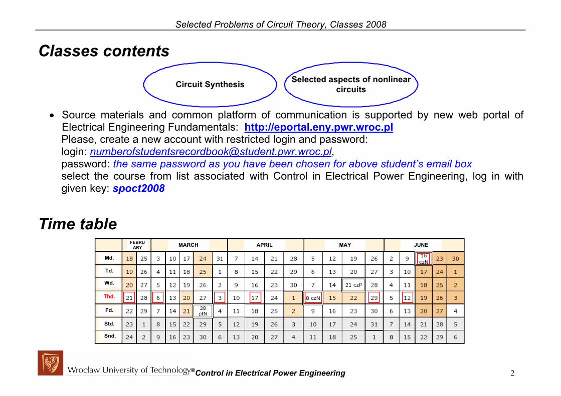
Classes contents
Circuit Synthesis Selected aspects of nonlinearcircuits
• Source materials and common platform of communication is supported by new web portal of
Electrical Engineering Fundamentals: http://eportal.eny.pwr.wroc.pl Please, create a new account with restricted login and password: login: [email protected], password: the same password as you have been chosen for above student’s email box select the course from list associated with Control in Electrical Power Engineering, log in with given key: spoct2008
Time table FEBRU
ARY MARCH APRIL MAY JUNE
Md.
Td.
Wd.
Fd.
Std.
Snd.
Thd.
®Control in Electrical Power Engineering 2

Selected Problems of Circuit Theory, Classes 2008
Requirements or how to pass this course
Active contribution in thecourse Final homework
Desirable mark
• Active contribution: short solution of given problems, activities in groups, short competitions
• Final homework: detailed work containing description of selected subject belonging to the course topics with set of literature, example of own problems and its solutions, analytic checking or results of computer simulation
®Control in Electrical Power Engineering 3

Selected Problems of Circuit Theory, Classes 2008
Analysis – short review and reminding of knowledge Activity - start Please fill the empty “toolbox shelf” i.e. associate few selected analysis approach to conditions of circuit work or general system description
• Empty “toolbox shelf”
Steady state Transient state General system description
®Control in Electrical Power Engineering 4

Selected Problems of Circuit Theory, Classes 2008
• Selected set of analysis approach and system description
Relation between input and output in timedomain based on step response k(t) or impulseresponse h(t)
Toolbox 4 - Convolution
k(t),x(t) y(t)
h(t)( ) ( ) ( )
( ) ( ) ( )
dy t x t k tdt
y t x t h t
= ∗
= ∗
Transfer function H(s)Toolbox 5 - Laplace Transform
H(s), K(s)X(s) Y(s) ( )
( ) ( ) ( )( ) ( )Y S X s s K s
Y s X s H s
= ⋅ ⋅
= ⋅
Frequency characteristic of the systemToolbox 6 - Fourier Transform
( )H jω
( )H jω
( ) ( ) ( )jH j H e ϕ ωω ω= ⋅
Analysis in „s” domainToolbox 3 - Laplace Transform
( ) ( ) ( ) ( ) ( ) ( )( ) ( ) ( ) ( ) ( ) ( )
( ) ( ) ( )
, , , ,
, , , ,
, ( , , )
R L C R L C
R L C R L C
u t u t u t U s U s U s
i t i t i t I s I s I s
e t E s R L C Z s
→
→
→ →
Symbolic analysisToolbox 2 - sinusoidal excitation
( ) ( )( ) ( ) ( )
( ) ( ) ( )( )
sin
, , , ,
, , , ,
, ( , , )
m e
R L C R L C
R L C R L C
e t E t
u t u t u t U U U
i t i t i t I I I
e t E R L C Z
ω ψ= +
→
→
→ →
Simplified analysisToolbox 1 - constant excitation
( ) ( ) ( )( ) ( ) ( ) ( )
, , .
0, , 0, .R R
L L C c
e t E const u t const i t const
u t i t const i t u t const
= = = =
= = = =
Kirchhoff laws with universal relations between voltage andcurrent:
Toolbox 0 - universal approach
( )
( ) ( ) ( ) ( ) ( ) ( )any time function
, ,L cR R L C
e t
di t du tu t R i t u t L i t C
dt dt
−
= ⋅ = =
®Control in Electrical Power Engineering 5

Selected Problems of Circuit Theory, Classes 2008
• Activity solution: filled “toolbox shelf”
Steady state Transient state General system description
Simplified analysisToolbox 1 - constant excitation
( ) ( ) ( )( ) ( ) ( ) ( )
, , .
0, , 0, .R R
L L C c
e t E const u t const i t const
u t i t const i t u t const
= = = =
= = = =
Symbolic analysisToolbox 2 - sinusoidal excitation
( ) ( )( ) ( ) ( )
( ) ( ) ( )( )
sin
, , , ,
, , , ,
, ( , , )
m e
R L C R L C
R L C R L C
e t E t
u t u t u t U U U
i t i t i t I I I
e t E R L C Z
ω ψ= +
→
→
→ →
Kirchhoff laws with universal relations between voltage andcurrent:
Toolbox 0 - universal approach
( )
( ) ( ) ( ) ( ) ( ) ( )any time function
, ,L cR R L C
e t
di t du tu t R i t u t L i t C
dt dt
−
= ⋅ = =
Analysis in „s” domainToolbox 3 - Laplace Transform
( ) ( ) ( ) ( ) ( ) ( )( ) ( ) ( ) ( ) ( ) ( )
( ) ( ) ( )
, , , ,
, , , ,
, ( , , )
R L C R L C
R L C R L C
u t u t u t U s U s U s
i t i t i t I s I s I s
e t E s R L C Z s
→
→
→ →
Relation between input and output in timedomain based on step response k(t) or impulseresponse h(t)
Toolbox 4 - Convolution
k(t),x(t) y(t)
h(t)( ) ( ) ( )
( ) ( ) ( )
dy t x t k tdt
y t x t h t
= ∗
= ∗
Transfer function H(s)Toolbox 5 - Laplace Transform
H(s), K(s)X(s) Y(s) ( )
( ) ( ) ( )( ) ( )Y S X s s K s
Y s X s H s
= ⋅ ⋅
= ⋅
Frequency characteristic of the systemToolbox 6 - Fourier Transform
( )H jω
( )H jω
( ) ( ) ( )jH j H e ϕ ωω ω= ⋅
Activity - end
®Control in Electrical Power Engineering 6

Selected Problems of Circuit Theory, Classes 2008
Analysis vs Synthesis Analysis problem: Synthesis problem: Given the structure and the input of the system we determinate its output
Given the input and the output of the system we wish to find its structure
The answer of analysis (systematic approach): The answer of the synthesis (design approach): There is one answer
Sometimes there is no answer and often the answer is not unique
The available elements for the synthesis
Passive circuits Active circuits
One-port circuit(Driving Point Immittance)
Two-port circuit(Transfer Immittance, Filter
design)
Synthesis
LCclass
RLclass
RCclass
RLCclass
®Control in Electrical Power Engineering 7
Selected Problems of Circuit Theory, Classes 2008
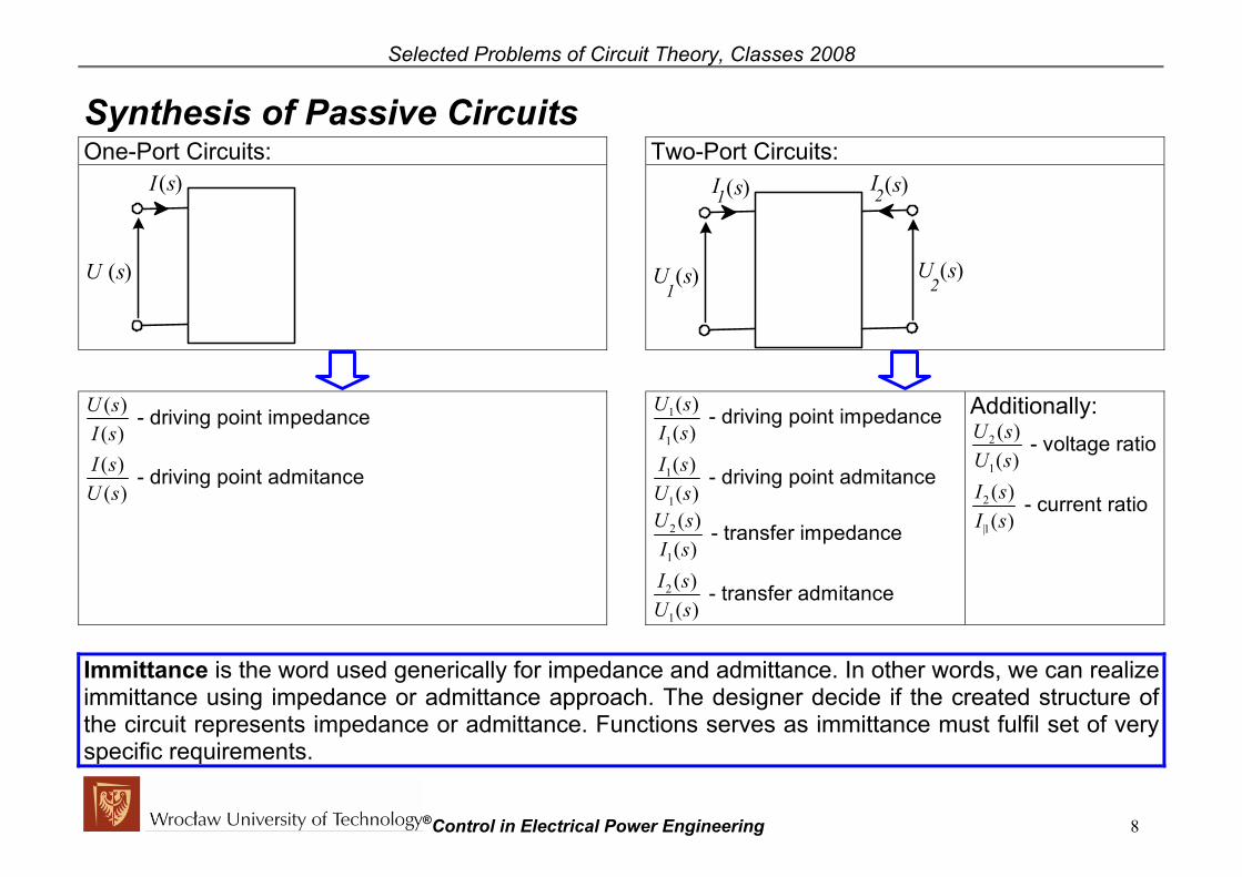
Synthesis of Passive Circuits One-Port Circuits: Two-Port Circuits:
I (s)
U (s)
U (s)
I (s)
U (s)1
1
2
I (s)2
1
1
1
1
( )( )( )( )
U sI sI s
U s
- driving point impedance
- driving point admitance
2
1
2
1
( )( )( )( )
U sI sI sU s
- transfer impedance
- transfer admitance
Additionally: 2
1
2
|1
( )( )( )
U sI sI s
- voltage ratio
- current ratio
( )U s
( )( )( )( )
U sI sI s
U s
- driving point impedance
- driving point admitance
Immittance is the word used generically for impedance and admittance. In other words, we can realize immittance using impedance or admittance approach. The designer decide if the created structure of the circuit represents impedance or admittance. Functions serves as immittance must fulfil set of very specific requirements.
®Control in Electrical Power Engineering 8

Selected Problems of Circuit Theory, Classes 2008 Immittance and rational positive real function A network with finite number of R,L,C elements has a driving point immittance, one-port impedance Z(s) or admittance Y(s), of the rational form:
( ) ( )( )
11 1 0
11 1 0
......
n nn n
m mm m
N s a s a s a s aF sD s b s b s b s b
−−
−−
+ + + += =
+ + + +
Given function F(s) can be immittance of design RLC passive circuit (in Z(s) or Y(s) form) only if fulfil requirements for being rational positive real function. Condition for real character of F(s) (necessary and sufficient):
, ,..., ,a a a aC.R.1. coefficient of numerator ( 0 ) and denominator ( ) polynomials must be real
1 1n n− 1 1 0, ,..., ,m mb b b b−
Conditions for positive character of F(s) (sufficient): , ,..., ,a a aC.P.1. coefficient of numerator ( 0 ) and denominator ( )
polynomials must have the same sign 1 1n n a− 1 1 0, ,..., ,m mb b b b−
C.P.2. power of “s” in numerator and denominator may differ at most by 1 ( { }( ) 1,0n m ,1− ⊂ − ) C.P.3. Poles and zeros must lie on the left-hand half plane or on the imaginary axis C.P.4. If the poles and zeros lie on the imaginary axis their must be single (real s=0 or in conjugate pairs s jω= ± ) and F(s) must have positive, real residues for poles ( ( ) ( ) ( )
polepoles s
res F s s F s=
⋅limpoles s
s→
= − ), and positive, real derivative for zeros ( )'zeroF s
C.P.5. replacing s jω= obtained form must have positive real part ( ){ }Re 0 0 for F jω ω≥ ≤ ∞≤
®Control in Electrical Power Engineering 9
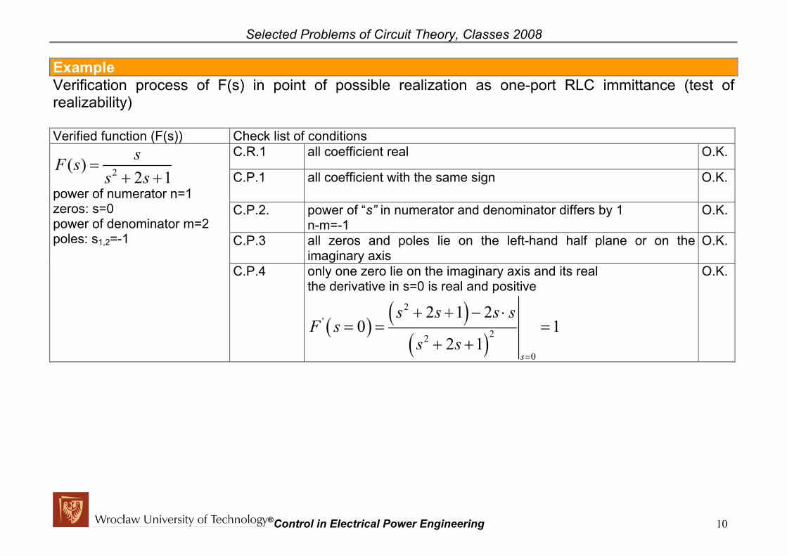
Selected Problems of Circuit Theory, Classes 2008 Example Verification process of F(s) in point of possible realization as one-port RLC immittance (test of realizability) Verified function (F(s)) Check list of conditions
C.R.1 all coefficient real O.K.
C.P.1 all coefficient with the same sign O.K.
C.P.2. power of “s” in numerator and denominator differs by 1 n-m=-1
O.K.
C.P.3 all zeros and poles lie on the left-hand half plane or on the imaginary axis
O.K.
2( )2 1
F ss s
=s
+ +
power of numerator n=1 zeros: s=0 power of denominator m=2 poles: s1,2=-1
C.P.4 only one zero lie on the imaginary axis and its real the derivative in s=0 is real and positive
( ) ( )( )
2'
22
0
2 1 20 1
2 1s
s s s sF s
s s=
+ + − ⋅= = =
+ +
O.K.
®Control in Electrical Power Engineering 10

Selected Problems of Circuit Theory, Classes 2008 C.P.5
( )( )
( )( )
( )( )
2 2
2 2 2
2 22 2 2 2
1 22 1
1 2 2 1
1 4 1 4
j jF jjj j
j j j
ω ωωω ωω ω
ω ω ω ω ω ω
ω ω ω ω
= = =− ++ +
⋅ − − + − = =− + − +
;
Thus, ( ){ }( )
2
22 2
2Re1 4
F j ωωω ω
=− +
and its real and positive
for al 0 ω≤ ≤ ∞
O.K.
Final decision: Circuit possible for design and realization in RLC passive class
®Control in Electrical Power Engineering 11
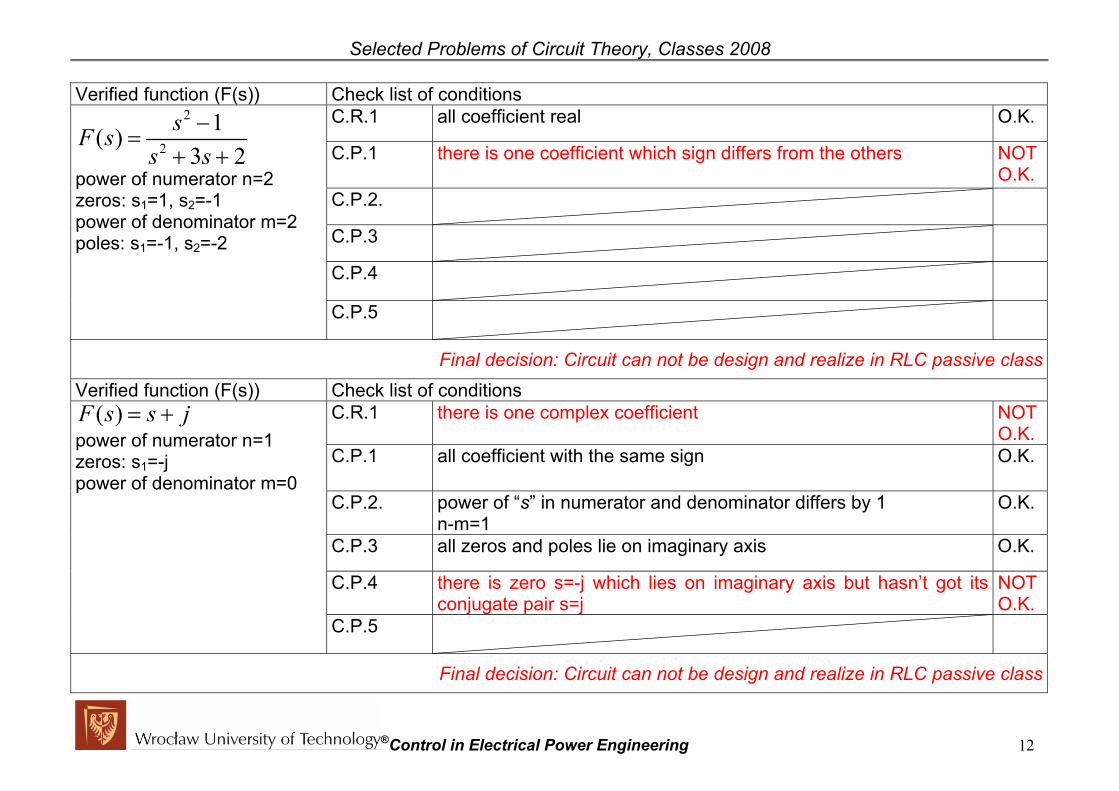
Selected Problems of Circuit Theory, Classes 2008 Verified function (F(s)) Check list of conditions
C.R.1 all coefficient real O.K.
C.P.1 there is one coefficient which sign differs from the others NOT O.K.
C.P.2.
C.P.3
C.P.4
2 1s −2( )
3 2F s
s s=
+ +
power of numerator n=2 zeros: s1=1, s2=-1 power of denominator m=2 poles: s1=-1, s2=-2
C.P.5
Final decision: Circuit can not be design and realize in RLC passive class Verified function (F(s)) Check list of conditions
C.R.1 there is one complex coefficient NOT O.K.
C.P.1 all coefficient with the same sign O.K.
C.P.2. power of “s” in numerator and denominator differs by 1 n-m=1
O.K.
C.P.3 all zeros and poles lie on imaginary axis O.K.
C.P.4 there is zero s=-j which lies on imaginary axis but hasn’t got its conjugate pair s=j
NOT O.K.
( )F s s j= + power of numerator n=1 zeros: s1=-j power of denominator m=0
C.P.5
Final decision: Circuit can not be design and realize in RLC passive class
®Control in Electrical Power Engineering 12

Selected Problems of Circuit Theory, Classes 2008 Activity – beginning Verify if given function F(s) can be realized as one-port RLC immittance (test of realizability)
a) 2
2
2( )4 3
s sF ss s
+=
+ + e)
2
4 2
7 5 1( )1
s sF ss s s
+ +=
+ + +
b) 2
4( )3 2
sF ss s
+=
+ + f) 2
2 1( )3 2
sF ss s
+=
+ +
c) 2
3 1( )7 5 1
sF ss s
−=
+ + g) ( ) 3F s s= +
d) 2( ) 1F s s= + h) 2
1( )4
sF ss s
+=
+
®Control in Electrical Power Engineering 13

Selected Problems of Circuit Theory, Classes 2008
• Activity solution:
a) 2
2
2( )4 3
s sF ss s
+=
+ + O.K. e)
2
4 2
7 5 1( )1
s sF ss s s
+ +=
+ + +NOT OK. – C.P.2
b) 2
4( )3 2
sF ss s
+=
+ + NOT OK. – C.P.5 f) 2
2 1( )3 2
sF ss s
+=
+ + O.K.
c) 2
3 1( )7 5 1
sF ss s
−=
+ + NOT OK. – C.P.1 g) ( ) 3F s s= + O.K.
d) 2( ) 1F s s= + NOT OK. – C.P.2 h) 2
1( )4
sF ss s
+=
+ O.K.
Activity - End
®Control in Electrical Power Engineering 14
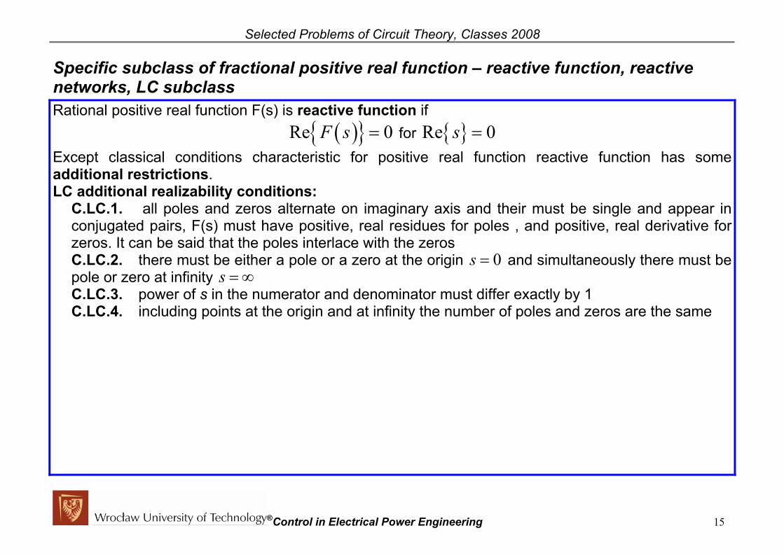
Selected Problems of Circuit Theory, Classes 2008 Specific subclass of fractional positive real function – reactive function, reactive networks, LC subclass Rational positive real function F(s) is reactive function if
( ){ }Re 0F s = for { }Re 0s = Except classical conditions characteristic for positive real function reactive function has some additional restrictions. LC additional realizability conditions:
C.LC.1. all poles and zeros alternate on imaginary axis and their must be single and appear in conjugated pairs, F(s) must have positive, real residues for poles , and positive, real derivative for zeros. It can be said that the poles interlace with the zeros C.LC.2. there must be either a pole or a zero at the origin 0s = and simultaneously there must be pole or zero at infinity s = ∞ C.LC.3. power of s in the numerator and denominator must differ exactly by 1 C.LC.4. including points at the origin and at infinity the number of poles and zeros are the same
®Control in Electrical Power Engineering 15

Selected Problems of Circuit Theory, Classes 2008 A network with finite number of L,C elements has a driving point immittance, now understood as reactive function, and can be described by 4 below formulas:
( )( ) ( )( )( ) ( )
( )( ) ( )2 2 2 2
1 3 2 1
2 2 2 2 2 22 4
1 2 3 4 2 2 1
...
...
: 0, ...
n
n
n n
s s sN sF s K
D s s s s s
where K
ω ω ω2 2
2ω ω ω
ω ω ω ω ω ω
+
+
+ + += =
+ + +
> < < < < < <
(pole at the origin, pole at infinity)
( ) ( )( )
( )( ) ( )( )( ) ( )
2 2 2 2 2 21 3 2 1
2 2 2 2 2 22 4
1 2 3 4 2 1 2
...
...
: 0, ...
n
n
n n
s s sN sF s K
D s s s s s
where K
ω ω ω
2ω ω ω
ω ω ω ω ω ω
−
−
+ + += =
+ + +
> < < < < < <
(pole at the origin, zero at infinity)
( ) ( )( )
( )( ) ( )( )( ) ( )
2 2 2 2 2 22 4 2
2 2 2 2 2 21 3
1 2 3 4 2 2 1
...
...
: 0, ...
n
n
n n
s s s sN sF s K
D s s s s
where K2 1
ω ω ω
ω ω ω
ω ω ω ω ω ω+
+
+ + += =
+ + +
> < < < < < <
(zero at the origin, zero at infinity)
( ) ( )( )
( )( ) ( )( )( ) ( )
2 2 2 2 2 22 4 2
2 2 2 2 2 21 3
1 2 3 4 2 1 2
...
...
: 0, ...
n
n
n n
s s s sN sF s K
D s s s s
where K2 1
ω ω ω
ω ω ω
ω ω ω ω ω ω−
−
+ + += =
+ + +
> < < < < < <
(zero at the origin, pole at infinity)
®Control in Electrical Power Engineering 16

Selected Problems of Circuit Theory, Classes 2008
Illustration of four possible form of reactive function in complex plane:
1s jω=
1s jω= −
2s jω=
2s jω= −
3s jω=
1s jω=
1s jω= −
2s jω=
2s jω= −
3s jω=
4s jω=
4s jω= −
1s jω=
1s jω= −
2s jω=
2s jω= −
3s jω=
1s jω=
1s jω= −
2s jω=
2s jω= −
3s jω=
4s jω=
4s jω= −
pole at the origin, pole at infinity
pole at the origin, zero at infinity
zero at the origin, zero at infinity
zero at the origin, pole at infinity
( )( )( )
2 2 2 2
2 ( )
( )( )2 2
( )( )
( )( )2 2 2 2
Example 1 Example 2 Example 3 Example 4 Simply way of verification if given rational positive real function is the reactive function can be done by geometrical representation of their poles and zeros.
®Control in Electrical Power Engineering 17
( ) 1 32 2
2
1 2 3:
s sF s
s s
where
ω ω
ω
ω ω ω
+ +=
+
< <
( ) ( )( )( )( )
2 2 2 21 3
2 2 22 4
1 2 3 4:
s sF s
s s s
where
ω ω
ω ω
ω ω ω ω
+ +=
+ +
< < <
( ) 22 2 2 2
1 3
1 2 3:
s sF s
s s
where
ω
ω ω
ω ω ω
+=
+ +
< <
( ) 2 42 2 2 2
1 3
1 2 3 4:
s s sF s
s s
where
ω ω
ω ω
ω ω ω ω
+ +=
+ +
< < <
3s jω= −3s jω= −3s jω= −3s jω= −
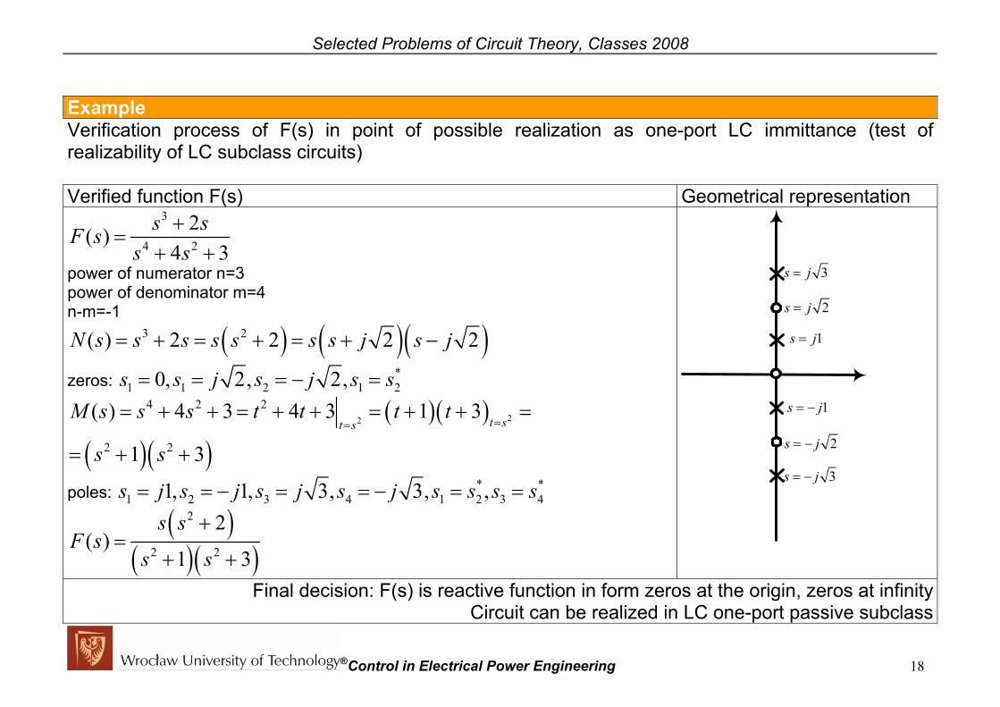
Selected Problems of Circuit Theory, Classes 2008 Example Verification process of F(s) in point of possible realization as one-port LC immittance (test of realizability of LC subclass circuits) Verified function F(s) Geometrical representation
3 2s s4 2( )
4 3F s
s s+
=+ +
power of numerator n=3 power of denominator m=4 n-m=-1
( ) ( )( )3 2( ) 2 2 2 2N s s s s s s s j s j= + = + = + −
zeros: *1 1 2 1 20, 2, 2,s s j s j s s= = = − =
( )( )
( )( )22
4 2 2
2 2
( ) 4 3 4 3 1 3
1 3t st s
M s s s t t t t
s s==
= + + = + + = + + =
= + +
poles: * *1 2 3 4 1 2 3 41, 1, 3, 3, ,s j s j s j s j s s s s= = − = = − = =
( )( )( )
2
2 2
2( )
1 3
s sF s
s s
+=
+ +
1s j=
1s j= −
2s j=
2s j= −
3s j=
3s j= −
Final decision: F(s) is reactive function in form zeros at the origin, zeros at infinity Circuit can be realized in LC one-port passive subclass
®Control in Electrical Power Engineering 18

Selected Problems of Circuit Theory, Classes 2008 Activity – beginning Verify if given function F(s) represents reactive function (test of realizability of LC subclass of circuits)
a) 2
2
1( )2
sF ss
+=
+ e)
2 1( ) sF ss+
=
b) ( )2
2
1( )2
sF ss s
+=
+ f) ( ) 2 1
sF ss
=+
c) ( )2
2
2( )1
sF ss s
+=
+ g) ( ) 2 1
sF ss s
=+ +
d) 2
1( )1
F ss
=+
h) 2( )1
sF ss
=−
®Control in Electrical Power Engineering 19

Selected Problems of Circuit Theory, Classes 2008
• Activity solution:
a) 2
2
1( )2
sF ss
+=
+ NOT O.K.- C.LC.2 e)
2 1( ) sF ss+
= O.K
b) ( )2
2
1( )2
sF ss s
+=
+ O.K. f) ( ) 2 1
sF ss
=+
O.K.
c) ( )2
2
2( )1
sF ss s
+=
+ NOT O.K.- C.LC.1 g) ( ) 2 1
sF ss s
=+ +
NOT O.K. – C.LC.1
d) 2
1( )1
F ss
=+
NOT O.K. - C.LC.2 h) 2( )1
sF ss
=−
NOT O.K. – C.LC.1
®Control in Electrical Power Engineering 20