selecting the best carburizing method for the heat ... · heat treatment process and a viable...
TRANSCRIPT

Selecting the Best CarburizingMethod for the Heat Treatment of Gears
Daniel H. HerringThe HERRING GROUP, Inc.
David J. Breuer Gerald D. LindellMetal Improvement Company, Inc Twin Disc, Inc.
ABSTRACT
A very good compromise between cost andperformance is achieved by atmospherecarburizing, the present day de facto standardprocessing method used in the gear industry. Atypical workload is shown in Figure 1.
All indications are, however, that the greatestpotential for future growth will come in vacuumcarburizing. Figure 2 shows a load of gears readyto be charged into a typical vacuum carburizer.This method of carburizing has been shown tooffer proven metallurgical and environmentalbenefits.
For the industry to stay competitive bothtechnologies will be needed in the future. This isto insure that the challenges posed by everincreasing performance requirements in smallerpackages and by a new generation of materialsand manufacturing methods can be met.
INTRODUCTION
Of paramount importance today is lowering unitcost that can only be achieved by improveddimensional control and more cost effectivemanufacturing methods. The benefits achievedby vacuum carburizing can be realized in highvolume, critical component manufacturing.
Vacuum carburizing has proven itself a robustheat treatment process and a viable alternative toatmosphere carburizing. Gear manufacturers ofheavy duty, off-road transmissions and relatedequipment such as Twin Disc Corporation havefound numerous benefits in substituting vacuumcarburizing with high gas pressure quenching foreither atmosphere or vacuum carburizing with oilquenching technology. This paper will presentscientific data in support of this choice.
Figure 1: Load of Production Gears (650 lbs net)in Position for Loading into an AtmosphereCarburizing Furnace followed by Oil Quenching.
Figure 2: Load of Production Gears (650 lbs net)in Position for Loading into a VacuumCarburizing Furnace followed by High GasPressure or Oil Quenching

HISTORICAL BACKGROUND
It is unfortunate that atmosphere and vacuumtechnology are viewed as competitors instead ofas complements to one another. The existing “usversus them” mentality created by constantnegative comparisons has hurt both technologies.
In the 1960s the need for better atmospherecontrol prompted a series of R&D efforts to finda solution. One of these led to the developmentof vacuum carburizing, viewed as an alternativeto atmosphere carburizing providing enhancedmetallurgical properties and shorter cycle times.However, it was promoted within the heattreatment industry as a panacea for all theproblems of atmosphere carburizing, and, thus,initiated competition between the twotechnologies.
Had vacuum carburizing proved to be a robusttechnology at that time, it is generally believedthat a significant portion of today’s installedequipment base would use this technology. Itsfailure to achieve commercial success can bedirectly related to reliability and cost. Thecreation of soot was the Achilles heel of vacuumcarburizing. Perhaps a more accurate statement isthat the equipment designs and processparameters of vacuum carburizing were notoptimized, and the technology’s capabilitiesoversold to the heat-treating community.
Today these problems have been addressed andsooting is no longer a limitation of the process.New equipment designs, controls, andprocessing methods assure excellent up timeproductivity and high volume capacities.
POWER TRANSMISSION COMPONENTS
The application and manufacture of high qualitytransmission gearing used in demandingapplications such as shown in Figures 3 and 4require careful consideration of a number ofcritical factors including: component design;material selection; heat treatment method; andthe influence of post heat treatmentmanufacturing operations.
Gearing is subject to both sliding and rollingcontact stresses on the gear flanks in addition tobending stress in the tooth roots. The mostdesirable gear properties to meet these twocriteria would be hardened gears for strength andcontact properties with residual compressivesurface stress for bending fatigue properties.
Figure 3: Typical heavy duty Transmission Usedfor Airport Fire Vehicles.
Fatigue is a major cause of failure in gears.Fatigue failures fall into two classes: tooth rootbending fatigue and tooth flank contact relatedfailures. In this work residual stress andmicrohardness testing were used as indicators tocompare the atmosphere and vacuum carburizingprocesses.
Figure 4: Heavy Duty Marine TransmissionTransfer Gears.
The greater the magnitude and depth ofcompressive stress the greater the ability toimprove fatigue properties. A high compressivestress value at the surface helps the componentresist crack initiation. The deeper thecompressive layer the greater the resistance tocrack growth for longer periods of time.

Residual stress values are an important factor infatigue critical components. Residual stresses areadditive with applied stress. Compressiveresidual stresses are desired as they oppose theapplied, repetitive, and undesirable tensile stressthat causes fatigue failure. X-ray diffractionmethods allow measurement of residual stresslevels.
For the purposes of this investigation, thevacuum and atmosphere carburizing processeswere studied using x-ray diffraction techniquesand microhardness measurements. Specimens ofAISI 8620 material were manufactured,carburized by the different methods andsubjected to identical post heat treatmentoperations. Grinding and shot peening wereselected as representative.
CARBURIZING PROCESSES
Carburizing of a steel surface is both a functionof the rate of carbon absorption into the steel andthe diffusion of carbon away from the surfaceand into the metal. Once a high concentration ofcarbon has developed on the surface, duringwhat is commonly called the "boost stage", theprocess normally introduces a "diffuse stage"where solid state diffusion occurs over time. Thisstep results in a change in the carbonconcentration, or carbon gradient between thecarbon rich surface and the interior core of themetal. The result is a reduction of the carbonconcentration at the surface while increasing thedepth of carbon absorption.
In the carburization process the residualcompressive stress results from the delayedtransformation and volume expansion of thecarbon-enriched surface. This induces thedesirable residual compressive stress through thecase hardened layer.
Atmosphere Carburizing
Atmosphere carburizing is an empirically based,time-proven process in which a carbon-richatmosphere surrounding a workload is used tochemically react with the surface of the parts toallow an adequate quantity of carbon to beabsorbed at the surface and diffused into thematerial.
In atmosphere carburizing parts are heated toaustenitizing temperature in an Endothermic orequivalent atmosphere containing approximately40% hydrogen, 40% nitrogen, and 20% carbonmonoxide. Small percentages of carbon dioxide(up to 1 1/2%), water vapor (up to 1%), andmethane (up to 1/2%) along with trace amountsof oxygen are also present. This "neutral" or"carrier gas" atmosphere is generally consideredneither carburizing nor decarburizing to thesurface of the steel.
In order to perform the carburizing processenriching gas is added to the carrier gasatmosphere. The enriching gas is usually eithernatural gas which is about 90 - 95% methane(CH4) or propane (C3H8). In atmospherecarburizing it is common practice to begin theflow of enrichment gas just after the furnace hasrecovered setpoint. This practice contributes tocase non-uniformity as various parts of theworkload are not uniform in temperature andcarburize at different rates.
The water gas reaction (Equation 1) is importantin the control of the atmosphere carburizingprocess. Instruments such as dew point analyzersmonitor the H2O/H2 ratio of this equation whileinfrared analyzers and oxygen probes look at theCO/CO2 ratio.
CO + H2O = CO2 + H2 (1)
In atmosphere carburizing, intergranularoxidation is one of the phenomena taking placeas a result of the constant changes occurring inthe furnace atmosphere.
This can be explained by considering analternative form of the water gas reaction(Equation 2). Here we see that the transfer ofcarbon in atmospheres containing CO and H2 isconnected with a transfer of oxygen, giving riseto an oxidation effect in steel with alloyingelements such as silicon, chromium, andmanganese
CO + H2 = [C] + H2O (2)
Figure 5 shows results from an actual gearsample that was atmosphere carburized.
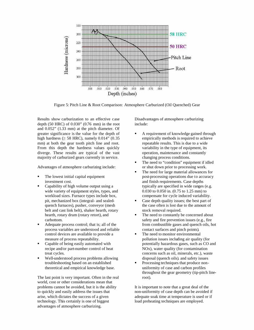
Figure 5: Pitch Line & Root Comparison: Atmosphere Carburized (Oil Quenched) Gear
Results show carburization to an effective casedepth (50 HRC) of 0.030” (0.76 mm) in the rootand 0.052” (1.33 mm) at the pitch diameter. Ofgreater significance is the value for the depth ofhigh hardness (≥58 HRC), namely 0.014” (0.35mm) at both the gear tooth pitch line and root.From this depth the hardness values quicklydiverge. These results are typical of the vastmajority of carburized gears currently in service.
Advantages of atmosphere carburizing include:
The lowest initial capital equipmentinvestment cost.
Capability of high volume output using awide variety of equipment styles, types, andworkload sizes. Furnace types include box,pit, mechanized box (integral- and sealed-quench furnaces), pusher, conveyor (meshbelt and cast link belt), shaker hearth, rotaryhearth, rotary drum (rotary retort), andcarbottom.
Adequate process control; that is; all of theprocess variables are understood and reliablecontrol devices are available to provide ameasure of process repeatability.
Capable of being easily automated withrecipe and/or part-number control of heattreat cycles.
Well-understood process problems allowingtroubleshooting based on an establishedtheoretical and empirical knowledge base.
The last point is very important. Often in the realworld, cost or other considerations mean thatproblems cannot be avoided, but it is the abilityto quickly and easily address the issues thatarise, which dictates the success of a giventechnology. This certainly is one of biggestadvantages of atmosphere carburizing.
Disadvantages of atmosphere carburizinginclude:
A requirement of knowledge gained throughempirically methods is required to achieverepeatable results. This is due to a widevariability in the type of equipment, itsoperation, maintenance and constantlychanging process conditions.
The need to “condition” equipment if idledor shut down prior to processing work.
The need for large material allowances forpost-processing operations due to accuracyand finish requirements. Case depthstypically are specified in wide ranges (e.g.0.030 to 0.050 in. (0.75 to 1.25 mm) tocompensate for cycle induced variability.
Case depth quality issues; the best part ofthe case often is lost due to the amount ofstock removal required.
The need to constantly be concerned aboutsafety and fire prevention issues (e.g., firefrom combustible gases and quench oils, hotcontact surfaces and pinch points).
The need to monitor environmentalpollution issues including air quality (forpotentially hazardous gases, such as CO andNOx), water quality (for contaminationconcerns such as oil, minerals, etc.), wastedisposal (quench oils). and safety issues
Processing techniques that produce non-uniformity of case and carbon profilesthroughout the gear geometry (tip-pitch line-root).
It is important to note that a great deal of thenon-uniformity of case depth can be avoided ifadequate soak time at temperature is used or ifload preheating techniques are employed.

Vacuum Carburizing
Vacuum carburizing is a proven method of purecarburizing and pure diffusion in which carbonpenetrates into the surface of the steel beingprocessed without interference from externalinfluences such as gas chemistry or surfacecontaminants.
Vacuum carburizing is a modified gascarburizing process in which the carburizing isdone at pressures far below atmospheric pressure(760 Torr). The typical pressure range for lowpressure vacuum carburizing is 1-20 Torr.
The advantage of this method is that the steelsurface remains very clean and the vacuumenvironment makes the transfer carbon to thesteel surface faster (higher carbon flux values)since atmosphere interactions such as found inthe water gas reaction do not take place. Inaddition no intergranular oxidation can occur.
The carbon produced by the breakdown of thehydrocarbon gas introduced into the chamber isfree to penetrate into the surface of the steelwhile the hydrogen and residual hydrocarbonbyproducts are removed from the system by thevacuum pumps.
The hydrocarbon gases currently being used forvacuum carburizing are acetylene (C2H4),propane (C3H8) and to a lesser degree ethylene(C2H4). Methane (CH4) is essentially non-reactive at these low pressures, unless thetemperature is near 1900F (1040 C).
In vacuum carburizing the breakdown ofhydrocarbon gases involve non-equilibriumreactions. This means that the surface of the steelis very rapidly raised to the saturation level ofcarbon in austenite. By repeating the boost anddiffuse steps desired carbon profile and casedepth can be achieved.
Depending on the type of hydrocarbon gas used,carbon is delivered to the steel surface viareactions such as
C2H2 2C + H2 (1)
C3H8 C + 2CH4 (2a)
C3H8 C2H4 + CH4 C + 2CH4 (2b)
C3H8 C2H2 + H2 + CH4 C + 2CH4 (2c)
C2H4 C + CH4 (3)
The control of the low pressure vacuumcarburizing process is on a time basis. Thecarbon transfer rates are a function oftemperature, gas pressure, and flow rate.Simulation programs have been created todetermine the boost and diffuse times of thecycle.
Figure 6 shows results from an actual gearsample that has been low pressure vacuumcarburized.
Figure 6: Pitch Line & Root Comparison: Vacuum Carburized (Oil Quenched) Gear

Results show carburization to an effective casedepth (50 HRC) of 0.040” (1.00 mm) in the rootand 0.052” (1.33 mm) at the pitch diameter. Ofgreater significance was the value for the depthof high hardness (≥58 HRC), namely 0.032”(0.80 mm) at both the gear tooth pitch line androot.
The overall case depth of maximum hardness forthe vacuum carburized part is noticeably deeperthan the atmosphere carburized part in Figure 5.
One also observes a far greater consistency in theroot and pitch line hardness through the depth ofhigh hardness.
Figure 7 below shows an actual gear sample thathas been vacuum carburized and high gaspressure quenched. These results, whencompared to Figure 5 and Figure 6 allow us toconclude that a more uniform case depth hasbeen developed between the gear pitch line androot.
Figure 7: Pitch Line & Root Comparison: Vacuum Carburized (High Gas Pressure Quenched) Gear
This is due in large part to the absence of a vaporlayer in gas quenching resulting in a moreuniform quenching rate in the gear tooth and rootprofiles.
Advantages of vacuum carburizing include:
Absence of intergranular oxidation. Capability of higher temperatures due to the
type of equipment and the nature of theprocess.
Process and cycle flexibility allows a widervariety of materials to be processed.
Processing methods produce more uniformcase and carbon profiles throughout the geartooth geometry (tip-pitch line-root).
Easy integration into manufacturing. Theprocess is clean, safe, simple to operate andeasy to maintain. Also, working conditionsare excellent (that is, there are no openflames, heat and pollution).
Full automation capability using recipe orpart-number control of heat treating cycles.
Precise process control achieved usingcomputer simulations, which allowadjustments to established cycles.
Consumption of energy by the equipmentand process only when needed due to thenature of the vacuum operation.
Typically less distortion results providedadequate measures are taken in loading.
Disadvantages of vacuum carburizing include:
Higher initial capital equipment cost thanatmosphere carburizing equipment.
Part cleanliness is more critical in order toachieve desired results.
Empirical process control, which requiresprocessing loads to determine optimumsettings or to fine tune simulator.
Formation of soot and tar, which occur dueto the type, pressure, and quantity ofhydrocarbon gas introduced.
It is important to note that research during thepast six years has succeeded in findingcombinations of pressure, gas type, and flowparameters to minimize soot and tar formationand eliminate these factors as a concern in thevacuum carburizing process.

Shot Peening
Shot peening is a process that induces a highmagnitude, residual compressive stress. It ismost effective for parts subject to high cyclefatigue loading as the compressive stress at thesurface results in significantly enhanced fatiguelife. Figure 8 below illustrates a typical S-Ncurve for a high cycle fatigue application.
Figure 8: Stress versus Load Cycles
This graph shows that a linear reduction intensile stress results in an exponentialimprovement in fatigue life. A 35% reduction instress - from 110 ksi (759 MPa) to 70 ksi (483MPa) results in a 400% improvement in fatiguelife, - from 40,000 cycles to 160,000 cycles.Additional reductions in tensile stress result insignificantly more fatigue enhancement.
The residual compressive stress from shotpeening counteracts applied tensile stresses inthe material. The compressive stress from shotpeening is induced from small, spherical mediastriking the surface. The impact from eachparticle stretches the surface enough to yield it intension. The surface cannot fully restore itselfthus producing a permanent compressed state.
Shot peening is a surface treatment that results ina magnitude of residual compression that is ~ 55- 60% of the material’s ultimate tensile strengthat the surface where most fatigue cracks initiate.For carburized gears the amount of surfacecompression is typically 170 - 230 ksi (1173 –1587 MPa) offering significant improvement infatigue properties.
TEST METHODS
X-Ray Diffraction
X-ray diffraction measures residual stresses atsurface and sub-surface locations in a sample.The method is considered a surface analysistechnique since only a few atomic layers are
measured. The sub-surface measurements weremade by electrochemically removing smallamounts of material. These sub-surfacemeasurements were subsequently corrected forstress gradient and layer removal effects usingstandard analytical calculations.
The technique measures strain by measuringchanges in atomic distances. It is a direct, self-calibrating method that measures tensile,compressive, and neutral strains equally well.Strains are converted to stresses by multiplyingby elastic constants appropriate for the alloy andatomic planes measured.
For this study, chromium K radiation waschosen to diffract the (211) planes atapproximately 1562. The area measured wasnominally 4 mm in diameter.
TEST PROCEDURE
The following procedure was performed in orderto evaluate the influence of atmosphere andvacuum carburizing as well as the influence ofshot peening and grinding.
o Five coupons were cut and stampedfrom the same heat lot of AISI 8620.
o A separate manufacturing process wascreated for each coupon according tothe following stamped identifications:
o VC: Vacuum Carburizeo VC & SP: Vacuum Carburize &
Shot Peeno AC: Atmosphere
Carburizeo AC & SP: Atmosphere
Carburize & ShotPeen
o VC & DSP: Vacuum Carburize &Dual Shot Peen
o The coupons were sent out for vacuumor atmosphere carburizing.
o The coupons were ground to sizeremoving no more than 0.006” (0.15mm) from the non-stamped side.
o Three of the five coupons were sent outfor shot peening.
o All five coupons were sent out for X-ray diffraction analysis on the non-stamped side.

PROCESS COMPARISON
The carburizing parameters used are summarized in Table 1 below:
Table 1Carburizing Parameters
CarburizingMethod
Temperature BoostTime
(minutes)
DiffusionTime
(minutes)
HardeningTemperature
QuenchingMethod
Tempering
Atmosphere 1725F(940C)
300 120 1550F(845C)
Oil @ 60C(140F)
350F(175C)2 hours
Vacuum 1725F(940C)
32 314 1550F(845C)
Nitrogengas @ 20
bar*
350F(175C)2 hours
*Note: 1 bar = 14.7 psia
Influence of Carburizing Method
Vacuum carburizing produced a deeper casedepth of high (≥58 HRC) hardness as seen in
Figure 9 showing a comparison of atmosphereand vacuum carburized test coupons.
Figure 9: Comparison of Vacuum Carburizing Using High Pressure Gas Quenchingand Atmosphere Carburizing Using Oil Quenching

Figure 10 shows a comparison of coremicrostructure. Samples shown are from thepitch line with the area below the root showingsimilar results. Today, vacuum carburizingtechniques can employ either oil or high pressuregas quenching technology in the range of 6-20
bar using nitrogen, helium, argon or gas blends.A properly designed gas quench system willproduce a core microstructure in a heavy sectionthickness that consists of tempered martensitewith some transformation products (bainite andferrite) present in the microstructure as well.
Atmosphere or VacuumCarburized
& Oil Quenched Sample.Core microstructure consists of
tempered martensite.Core Hardness is 37 HRC.
AISI 8620 GearsPart Weight = 26 lbs.
Load Weight = 500 lbs net
Vacuum Carburized&Gas Quenched Sample.
Core microstructure consists oftempered martensite andtransformation products
Core Hardness is 29 HRC.
Figure 10: Comparison of Core Microstructure
Influence of Shot Peening
Figure 11 shows the residual stress distributionsof the carburizing processes followed bygrinding with shot peening.
Figure 11: Vacuum and Atmosphere CarburizedGround Samples With Single and Dual ShotPeening
The graph shows that a solid layer ofcompression exists using all three methods.From a fatigue standpoint, excellent resistance tothe initiation and growth of fatigue cracks willresult. The tensile stress required for a fatigue
crack to develop must first overcome thecompressive stress that is ~ 150 ksi (1035 MPa)at the surface and ~ 220 ksi 0.002” (1518 MPa0.051mm) below the surface.
The three residual stress curves have therepresentative shape of a carburized and shotpeened material. The maximum compressivestress of all three curves is similar and is ~ 220ksi (1518 MPa). This value is approximately 55 -60% of the material’s ultimate tensile strength atthe surface. Since all three coupons were 59 - 62HRC, they had similar hardness & tensilestrength (at the surface). The reason that thecurves shown in Figure 11 do not cross theneutral axis is due to the carburization processthat induces residual compressive stresses priorto shot peening.
The depth of the compressive stress layer is afunction of the intensity or energy of the shotstream. It can be increased by increasing the shotsize and/or velocity. The depth is the locationwhere the curves would cross the neutral axis(into tension) if the positively sloped lines wereextended. A deeper depth of compression isdesired as this is a layer resisting crack growth.The tradeoff to increasing the intensity is thatthere is additional cold work and material

displacement at the point of shot impact. Thisgenerally results in a less compressed surfacestress (at depth = 0.000”) and a more aggressivesurface finish.Figure 12 shows visually how increasing the shotpeening energy changes the shape of the residualstress curve.
Figure 12: Influence of Shot Peening Energy on Residual Stress
Coupon VC & DSP was dual peened. Dualpeening consists of shot peening the samesurface twice. First, a higher intensity is utilizedand then followed by a lower intensity, usuallywith a smaller media. The second peeningoperation is able to reduce the cold work at thesurface by improving the surface finish thusmaking the surface more compressed.
The use of dual shot peening should be weighedvia a cost/benefit analysis. Typically, dualpeening approximately doubles the cost whileoffering the potential to double or triple thefatigue life produced by a single shot peen.
An analysis of Figure 11 indicates that the bestfatigue performance should come from thecoupon dual shot peened as it has the bestcombination of surface compression andcompressive layer depth properties.
This is particularly evident between 0.003”(0.076 mm) and 0.008” (0.203 mm). At 0.004”(0.102 mm) below the surface there is still 200ksi (1380 MPa) of compression for the VC &DSP coupon versus 170 ksi (1173 MPa) forcoupon AC & SP and 145 ksi for coupon VC &SP.
The dual shot peened coupon should result in asignificant increase in high cycle fatigueproperties over the (single) peened coupons.
In terms of fatigue performance, the additional 5ksi (34.5 MPa) of compression measured in thevacuum carburizing coupon (without shotpeening or grinding) should yield significantincreases in gear life under high cyclic fatigueloading over the atmosphere carburized coupon.

CONCLUSIONS
The primary focus of this study was to determinewhich carburizing process was more suitable forheavy duty transmission gears manufacturedfrom AISI 8620 steel. Vacuum carburizing wasfound superior to atmosphere carburizing in thisinstance as the data in Table 2 indicates, for thefollowing reasons:
o Higher Surface Hardnesso Greater Depth of High Hardnesso Deeper Effective Case Depth in the
Tooth Rooto Higher Surface Residual Compressiono Uniformity of Case at Pitch line of the
Gear Flank & Roots
Table 2: Comparison of Atmosphere and Vacuum Carburizing Results
Process SurfaceHardness(before
grinding)
SurfaceHardness
(aftergrinding)
High (≥58HRC)Hardness
(coupons)
High (≥58HRC)Hardness
(gears)
SurfaceResidual
Compression(ksi)
Deviation ofCase at Pitch
Line
Vacuum 60 HRC 62 HRC 0.023” 0.032” 19.6 0.011”Atmosphere 59 HRC 58 HRC 0.008” 0.015” 14.2 0.026”
Both the atmosphere carburized and vacuumcarburized surfaces responded equally to the shotpeening treatment.
Maximum compressive stress: ~ 220ksi (1518 MPa)
Compressive layer depth: ~ .007” -.008” (0.178 - 0.203 mm)
The dual shot peening resulted in a greaterdepth of compression by ~ .001” - .002” (0.025- 0.051 mm). The surface stress of the dualpeening was very similar to the previouslydiscussed shot peened coupons at ~ 135 ksi (932MPa). The (higher) first peen would haveresulted in a less compressed surface but thesecondary peen further compressed it to ~ 135ksi (932 MPa).
RECOMMENDATION
Testing of actual gears must be performed toconclude with certainty that changes to themanufacturing process (material, geometry, heattreatment, shot peening, grinding) will yieldbenefits such as those observed in this study.
ACKNOWLEDGEMENT
The authors would like to thank BodycoteThermal Processing, Racine, Wisconsin for
atmosphere carburizing and Midwest Thermal-Vac, Kenosha, Wisconsin for the vacuumcarburizing of gears and test coupons and bothorganizations for the load photographs.
REFERENCES
1. Lindell, G., Herring, D., Breuer, D., and Matlock,B., An Analytical Comparison of Atmosphere andVacuum Carburizing Using Residual Stress andMicrohardness Measurements, 2001 Heat TreatingConference Proceedings, ASM International.
2. Herring, D., Pros and Cons of Atmosphere andVacuum Carburizing, Industrial Heating Magazine,January 2002.
3. Shot Peening Applications, 8 th Edition, MetalImprovement Company, 2001.
4. Herring, D., Practical and Scientific Aspects ofLow Pressure Carburizing, 2001 Heat TreatingConference Proceedings, ASM International.
5. Sugiyama, M., Acetylene Vacuum Carburizing,1998 Heat Treating Conference Proceedings, ASMInternational.
6. Ptashnik, William J., Influence of Partial PressureCarburizing: Its Effect on Bending FatigueDurability, Heat Treating Magazine, Pt. 1&2,June/July 1980.