selection and use of sealants on the exterior building
TRANSCRIPT

Selection and Use of Sealants on theExterior Building Envelope
Terence A. DaCosta, EIT, and Elizabeth P. Lewis, PE, LEED GAGale Associates, Inc.
163 libbey Parkway, Weymouth, Ma 02189
Phone: 800-659-4753 • fax: 781-335-6467 • e-mail: [email protected]
3 0 t h R C I I n t e R n a t I o n a l C o n v e n t I o n a n d t R a d e S h o w • M a R C h 5 - 1 0 , 2 0 1 5 d a C o S t a a n d l e w I S • 9

Abstract
a variety of vertical wall systems common in building construction, including panelized façades, fenestrations, and curtain walls, rely on sealant to provide a secondary (and often primary) weather-resistance barrier for the exterior building envelope. While sealant is frequently used in construction and restoration projects, the wide range of materials, as well as the various substrate materials and configurations, demand the appropriate selection and use of sealants to achieve long-term weatherproofing and service life. This presentation will demonstrate how to select a sealant based upon a comprehensive and systematic approach.
Speaker
Terence A. DaCosta, EIT— Gale Associates, Inc.
TErEnCE DaCOSTa is a project engineer in the Building Envelope Technology Group of Gale associates, inc. His responsibilities include performing investigations of existing failures (roofs, walls, windows), performing design calculations, drafting contract drawings, and performing construction period monitoring services and project management services to public and private clients nationally.
1 0 • d a C o S t a a n d l e w I S 3 0 t h R C I I n t e R n a t I o n a l C o n v e n t I o n a n d t R a d e S h o w • M a R C h 5 - 1 0 , 2 0 1 5

Selection and Use of Sealants on theExterior Building Envelope
INTRODUC TION A variety of wall systems and associated
components common in building construction—including panelized façades, fenestrations, and curtain walls—rely on sealant to provide the secondary (and often the primary) weather-resistance barrier for the exterior building envelope. While sealant is frequently used in building construction and restoration projects, the wide range of sealant materials, as well as the variation in substrate materials and configurations, demand the appropriate selection and use of sealant to achieve long-term weatherproofing and service life.
For many projects, where access can be difficult and often costly, long-lasting performance is paramount in reducing maintenance and future renovation expenditures. as such, an appropriate design must meet the project-specific performance require ments, taking into consideration the joint movement, material weathering, installation techniques, and interaction with various substrate types. For sealant replacement on existing buildings, it is also important to identify the various deficiencies in the existing sealant, deduce their causes, recognize the potential for the presence of hazardous materials (including asbestos and polychlorinated biphenyl [PCB]-containing materials), and understand how these issues may affect a sealant rehabilitation project. Furthermore, a comprehensive design should consider not only the compatibility of materials but also the interaction of the mechanical properties of the sealant mate
rial and substrate materials. While the appropriate material selection and design of sealant joints are aspects that will improve the joint performance, proper application techniques are also required to maximize the service life of the sealant. Through a comprehensive design approach founded in the industry standards that guide selection, design, specification, and installation of the sealant, solutions can be developed to meet the project’s needs.
SE AL ANT AND BAC KER MAT ERIAL S IN THE BUIL DING ENVELOPE
Sealants are common in the building envelope, and although colloquially referred to as caulking, design and c o ns t r uc t i o n professionals typically refer to sealant when describing elastomeric materials used in exterior applications to prevent water and air intrusion. The term “caulking” is generally used to describe older, low-performance
materials with little movement capability or can refer to the extruding or gunning of sealants. Sealants are utilized in construction joints, in panelized façades of various materials, control joints for concrete and masonry wall assemblies, expansion joints in various building construction types, at fenestration perimeters, as structural glazing, and in various roofing applications. While sealant is often required in the exterior building envelope, the inappropriate specification and installation of sealant materials and sealant configurations can cause premature failure, which can result in air and moisture infiltration with resultant detrimental effects on building components and occupants.
Photo 1 – Precompressed sealant.
Photo 2 – Precured silicone strips.
3 0 t h R C I I n t e R n a t I o n a l C o n v e n t I o n a n d t R a d e S h o w • M a R C h 5 - 1 0 , 2 0 1 5 d a C o S t a a n d l e w I S • 1 1
Sealant Types As previously mentioned, sealant is
available in multiple material compositions, with various properties, and is produced by numerous manufacturers. The most commonly used sealant materials contain polyurethane or silicone. Polyurethanes are generally characterized by their strong adhesion, movement capability, substrate compatibility, and color variation. Similarly, silicones are effective in high-movement joints, exhibit strong adhesion, have excellent ultraviolet radiation (UV) resistance, and have a long service life. Cured silicone can act as a bond breaker, so the reapplication of silicone as a sealant repair material will require attention to surface preparation. The use of dissimilar sealants on or in contact with silicones will result in a lack of bond. Once silicone is used on porous substrates, it is difficult to utilize nonsilicone sealants for future removal/replacement without extensive surface preparation. Moreover, uncured silicone can be prone to dirt pickup and staining of substrates. although not discussed in detail in this paper, sealant is also manufactured using latex materials, acrylics, butyl-based materials, and polysulfides. Butyl-based sealant is characterized by strong adhesion and excellent weathering in low-movement applications, such as window glazing. Polysulfide-based sealant exhibits strong chemical resistance and can be used in submerged applications. latex and acrylic sealants are typically used in low-movement interior applications such as kitchens and bathrooms and are generally not appropriate for exterior weather seals.
In addition to the typical liquid-applied sealants, preformed, pre-manufactured sealants are available and may be appropriate for certain types of joints. acrylic-impregnated backer foam with a precured silicone facing is available in precompressed strips, and often these seals are manufactured with bellows in the facer material to accommodate the movement of wider joints. Thin, precured, extruded silicone strips can be effective in retrofit applications, such as stripping-in of
exterior insulated finish systems (EiFS) or metal panel wall joints to create a barrier wall system. See Photos 1 and 2.
Accessory Materials in addition to the available sealant
types, there are also various types of backer materials on the market. Backer rods and bond-breaker tapes help to eliminate three-sided adhesion, which can induce internal stresses within the sealant, causing adhesive or cohesive failure. moreover, backer materials installed within the joint help to provide a constant depth of sealant, and the rounded cross-section creates an hourglass shape that allows the sealant material to expand and contract while maintaining maximum surface area and adhesion at the bond interface. By slightly compressing the backer material within the joint, the backer rod provides support for the backside of the sealant during joint tooling, inherently directing the tooling force laterally to the sides of the joint to cause the sealant to wet the substrates, which promotes an adhesive bond.
There are many different types of backer rods, typically composed of polyethylene,
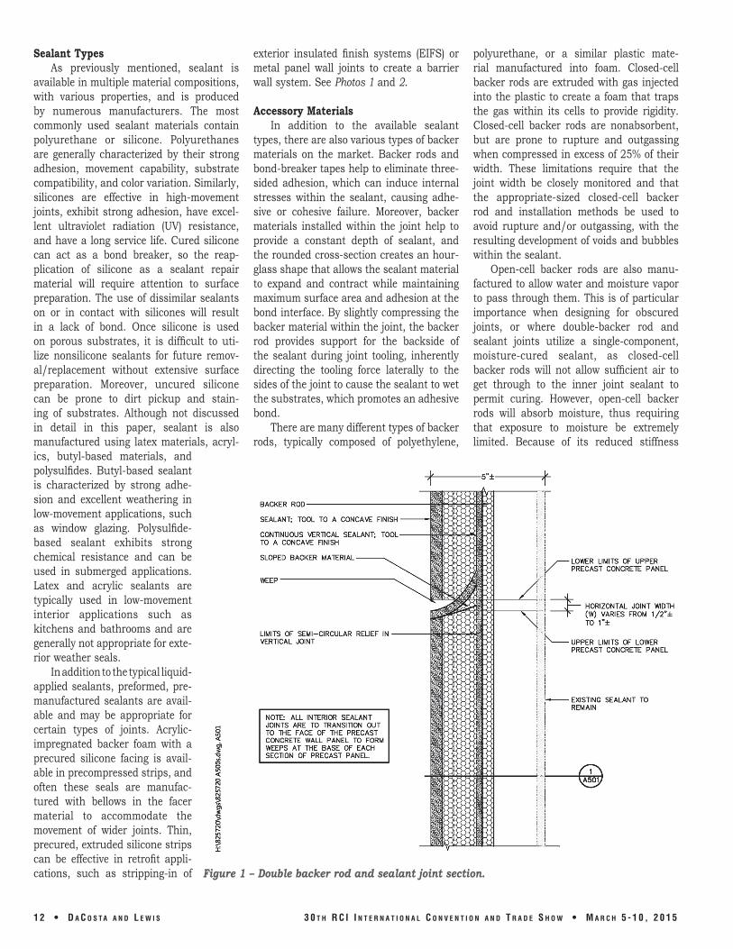
Figure 1 – Double backer rod and sealant joint section.
polyurethane, or a similar plastic material manufactured into foam. Closed-cell backer rods are extruded with gas injected into the plastic to create a foam that traps the gas within its cells to provide rigidity. Closed-cell backer rods are nonabsorbent, but are prone to rupture and outgassing when compressed in excess of 25% of their width. These limitations require that the joint width be closely monitored and that the appropriate-sized closed-cell backer rod and installation methods be used to avoid rupture and/or outgassing, with the resulting development of voids and bubbles within the sealant.
Open-cell backer rods are also manufactured to allow water and moisture vapor to pass through them. This is of particular importance when designing for obscured joints, or where double-backer rod and sealant joints utilize a single-component, moisture-cured sealant, as closed-cell backer rods will not allow sufficient air to get through to the inner joint sealant to permit curing. However, open-cell backer rods will absorb moisture, thus requiring that exposure to moisture be extremely limited. Because of its reduced stiffness
1 2 • d a C o S t a a n d l e w I S 3 0 t h R C I I n t e R n a t I o n a l C o n v e n t I o n a n d t R a d e S h o w • M a R C h 5 - 1 0 , 2 0 1 5

and soft composition, open-celled backer rods can be compressed in excess of 25%, and are capable of being installed with much greater compression, allowing for the same-size backer rod to be installed in a wider range of joint widths. State-of-the-art backer rods that utilize a dual-cell structure with a closed surface that will not outgas if ruptured are also available. additionally, premanufactured, precompressed acrylic-impregnated foams can also be used as a backer material, but should be considered primarily for areas highly exposed or excessively prone to moisture intrusion, as joint construction with these materials can be costly.
To provide redundancy for construction joints in a wall assembly, double backer and sealant joints can be utilized. See Figure 1. In these systems, two layers of sealant and backer rod are installed within a joint with a cavity or drainage space configured between the two sealant assemblies, as shown in Figure 1. While the outer layer of sealant is exposed to deterioration through weathering, the inner layer of sealant is protected from direct rain exposure and UV degradation. The drainage space and associated weep holes are required in the event that if the outer layer of sealant fails and becomes open to water infiltration, any moisture that bypasses the outer layer can drain and shed to the exterior. When this occurs, the inner sealant joint provides the waterproofing barrier to the building interior. Weeps must be constructed and located frequently enough to adequately drain the cavity and any potential moisture that may collect from other intersecting joints. Weep baffles are also recommended to reduce the potential for pest intrusion into the joint and blockage of the weep opening.
in some situations, the geometry of the joint prohibits the use of a backer rod. To prevent the issues that can occur with three-sided adhesion, bond-breaker tapes are appropriate for tight joints in which compressed backer rods cannot fit. in some instances, the use of a crayon to apply a wax coating to the backside of the joint can be more effective if the substrates are too rough or it is difficult to adhere bond-breaker tape. adhesion tests must be performed to confirm the suitability of such an application.
in addition to backer materials, substrate primers may be required to achieve the maximum adhesion to the substrates.
Different primers are available for different substrates, and while nonporous primers are typically required for metal substrates, the application of porous primers on masonry, concrete, and other substrates can have varying effects on adhesion between sealant and substrate. Similar to sealants, the effectiveness of primer is dependent on workmanship, and primer curing and tack time can vary significantly, depending on how much primer is applied, the porosity of the substrate, the ambient air conditions, and other environmental conditions.
CLASSIFICATION OF ELASTOMERIC SEALANT
While there is a plethora of technical information regarding the chemical and mechanical properties of sealants, understanding a few key principles is important when selecting sealant. Elastomeric sealants, which deform elastically when stressed under normal temperatures, are typically classified as being low-, medium-, or high-modulus. The modulus proper ties of sealant are defined as tensile stress over percent elongation and refer to the stiffness or elasticity of the material. The sealant stiffness will affect the stresses that will develop within the sealant and be transferred to the substrate. low-modulus sealant has high movement capabilities, remains relatively soft after cure, and can maintain strong adhesion to the substrates due to the ability to elongate at lower stresses. This makes low-modulus sealant appropriate for sealing joints in EiFS and other substrate materials with lower allowable tensile stresses, where joint movement could develop stresses that may damage the substrates. medium-modulus sealant is used most often and is appropriate for joints anticipated to experience low to moderate movement. High-modulus sealant is stiff, has low movement capabilities, and is commonly used for glazing applications.
although sealant can be described by the modulus, elastomeric sealants are classified under aSTm C920, Standard Specification for Elastomeric Joint Sealants by Type, Grade, Class, and Use, which categorizes cured sealants by their physical properties based on aSTm standard test method results. Sealant types can either be Type S, for single-component sealants requiring moisture and oxygen in the air to cure; or Type m, for multicomponent sealants that rely on the second component as a
chemical catalyst to cure the material. The different grades include Grade P, pourable or self-leveling for horizontal applications; and Grade nS, primarily for nonsag or gun-grade sealant for vertical applications. it is recommended that Grade P sealant not be installed in joints with a slope greater than 15 degrees.
Sealant is also categorized into class based on the adhesion and cohesion of elastomeric sealant when subjected to cyclic movement per aSTm standard test methods. Class 100/50 indicates that the sealant can be pulled to at least 100% of the joint width and compressed to 50%. Class 50 indicates it can be pulled in tension and can be compressed to at least 50%. Similarly, Class 35, Class 25, and Class 12½ sealant can withstand the numerical percent increases and decreases indicated compared to the original joint width.
in addition to classifying sealant based on type, grade, and class, aSTm C920 also designates sealant for various uses. Generally, use designation refers to suitable substrate materials or joint locations based on the associated aSTm test method results. Uses include “T1” for pedestrian and vehicular traffic areas where a harder sealant is required, “T2” for traffic areas where a softer sealant is desired, “nT” for nontraffic areas, “i” for submerged applications, “m” for mortar specimens, “G” for glass specimens, “a” for aluminum specimens, and “O” for other substrates. most sealants meet the requirements for multiple uses, but may not be appropriate for all use applications, depending on the other aSTm C920 classifications and the joint criteria.
FIELD EVALUATION OF EXISTING SEALANTS
in sealant renovation projects, an evaluation of the existing sealant is the first step in developing the appropriate sealant design. a systematic and comprehensive field evaluation—including but not lim ited to visual observations, destructive and nondestructive testing, and material sampling—is critical in identifying the existing conditions and ongoing issues that will be integrated into the design criteria. While certain types of sealant deficiencies are more common than others, it is important to be aware of all of them in order to effectively determine the performance requirements for sealant replacement.
The most noticeable sealant defect is
3 0 t h R C I I n t e R n a t I o n a l C o n v e n t I o n a n d t R a d e S h o w • M a R C h 5 - 1 0 , 2 0 1 5 d a C o S t a a n d l e w I S • 1 3

cohesive and/or adhe sive failure. Cohesive sealant failure is recognized by rips or tears within the sealant, often oriented parallel to the joint. Cohesive fail ure can be associated with a number of factors, including aging, UV exposure, heat degradation, poor joint design, and/or insufficient sealant thickness to accommodate anticipated joint movement. Adhesive sealant failure is characterized by loss of an adhesive bond between the sealant and the substrate.
While improper joint design or material selection can result in excess stresses transferred to the substrate at the bond line, the most common cause of adhesive failure is associated with inadequate or improper surface preparation. When performing an evaluation, destructive testing should be performed to review the substrates at the bond interface. Depending on
the removal methods, there is the potential that previous grinding of the substrates (particularly on concrete and masonry components) may have “polished” the substrate, thus eliminating open capillaries, which in turn inhibits adhesion. likewise, the
Photo 3 – Cohesive sealant failure.
Photo 4 – Crazed and adhesively failed sealant.
adhesive bond between the sealant and the substrate can be broken if polyurethane sealant is applied to joints previously sealed with silicone if the silicone material is not removed from the substrates. adhesion can also be compromised depending on the use
1 4 • d a C o S t a a n d l e w I S 3 0 t h R C I I n t e R n a t I o n a l C o n v e n t I o n a n d t R a d e S h o w • M a R C h 5 - 1 0 , 2 0 1 5

of primer, type of primer, and primer installation, illustrating the importance of design development or bid phase mock-up testing, which is discussed in more detail later in this paper. Poor joint geometry, including excessive thickness due to improperly placed or omitted backer rod, can limit the movement capabilities of a sealant, resulting in adhesive failure. See Photos 3 and 4.
In addition to the loss of the adhesive and cohesive properties of the sealant, substrate failure can occur when the sealant material is stronger than the substrate material and sufficient forces are generated to cause damage. as previously discussed, as a sealant joint experiences movement, the internal forces that develop within the sealant become transferred to the sub strates. If these internal forces exceed the allowable tensile stresses of the substrate materials, the substrates may incur cohesive separation, illustrating the importance of understanding the movement potential of the joint, and selecting and specifying a material with the appropriate modulus.
While multicomponent sealant may be advantageous, based on the joint location and anticipated cure mechanism, its performance is more dependent on workmanship due to the mixing requirements. if the mixing is not performed properly, the cure process can be disrupted and moisture can become trapped within the sealant. This can result in reversion, where the sealant loses elasticity and hardness, and appears similar to uncured sealant. Similarly, if a single-component sealant does not fully cure due to the joint location, excessive thickness, and general lack of moist air transmission, the sealant may be gummy and sticky to the touch.
Other common sealant defects include crazing and chalking of the surface. Crazing is often observed in existing sealant, particularly polyurethane sealants. When sealant is exposed to sunlight, UV can degrade the material over time and may result in a network of cracks developed in the exterior face of the sealant. Crazed sealant does not necessarily indicate that the joint is open to water infiltration unless the cracking extends through the sealant cross section, resulting in cohesive failure. However, crazing is a strong indication that the sealant performance is diminished and that the sealant is nearing the end of its service life. Exposure to UV in conjunction with weathering can also lead to the chemi
cal breakdown of the sealant, resulting in chalking, where a powder forms on the face of the sealant. Historically, both silicone and polyurethane sealants are susceptible to UV degradation, although many modern silicones now provide strong UV resistance.
although less common, sag, run-down, and fluid migration are other issues that may be observed on existing buildings. Sag can occur when the wrong material is installed in a vertical application or in slightly sloped joints that exceed the recommended tolerances. It is essential to recognize which materials are suitable for varying joint configurations. run-down and fluid migration are the result of fluids or other materials within the sealant leaching into or on the substrates and are typically characterized by staining of the substrates.
On panelized façades, fluid migration is often observed by edge staining or “picture framing” at the panel perimeters. Because these stains can be difficult to remove (particularly in natural stone), specifying nonstaining sealant for certain masonry applications may be required. The sealant itself can also become stained due to the accumulation of dirt. It is important to differentiate between dirt that has accumulated on the surface after cure and potential debris that may have been trapped within the outer layer of sealant during the curing process. The latter may affect the long-term performance of the joint.
While a survey of the existing sealant joints can identify visual defects, addi tional destructive testing is recommended to obtain sealant and substrate samples for hazardous material testing. This testing can confirm the existing condition and as-built joint configurations at multiple unique locations. Testing can also identify the degree of sealant failure that may not be determined from a visual review alone. additional destructive testing and mock-up installation of new sealant is recommended during the schematic design or design development phases.
asbestos and PCBs are the most common items found within sealant and may potentially be costly to properly abate in a renovation project. asbestos was a filler component previously added to ease placement and tooling. its use was banned in 1977, but asbestos can be found at concentrations between 1 and 5 percent in older sealants. although typically not difficult to abate, asbestos should be identified through
representative sampling and testing in the evaluation phase to avoid potential changes and added cost during construction. it is important to make the client aware that if testing for asbestos is not performed during the evaluation, the sealant contractor may perform its own testing independently after being hired and may seek additional compensation for abatement should the materials test positive.
it is not uncommon to encounter PCBs in building sealants installed prior to 1979, and in contrast to asbestos-containing materials, PCB testing and abatement can significantly impact a sealant replacement project. Discussing the impact of PCBs with your client and how the sealant should be tested and managed can be a sensitive issue, particularly for publicly occupied buildings. as such, it is important to communicate the potential concerns regarding PCBs to the client and possibly recommend the involvement of an environmental engineer or industrial hygienist specializing in the field of PCB abatement.
JOINT DESIGN AND SEALANT SELECTION
The design of the joint geometry and configuration, as well as the sealant and backer material selection, must be based on cumulative design criteria requirements developed from the building’s dynamic characteristics, façade materials, joint location and exposure, and any observed deficiencies for a rehabilitation project. The expected movement of joint should include not only the calculated tension and compression forces that will assist in selecting the appropriate class of sealant, but also the shear across the joint in both the parallel and orthogonal directions. aSTm C1472, Standard Guide for Calculating Movement and Other Effects When Establishing Sealant Joint Width, presents procedures for calculating movement, construction tolerances, and other factors that affect joint size. additional calculations should also be performed in accordance with aSCE 7, Minimum Design Loads for Buildings and Other Structures, and other applicable codes to determine additional forces that may be impact the sealant as the result of story drift, global deflection, and local deflection. When designing joints that have the potential to move in multiple dimensions, the sealant tensile properties, tear strength, and adhesion in peel from the appropri
3 0 t h R C I I n t e R n a t I o n a l C o n v e n t I o n a n d t R a d e S h o w • M a R C h 5 - 1 0 , 2 0 1 5 d a C o S t a a n d l e w I S • 1 5

Figure 2 – Sealant joint cross section.
ate substrate should all be reviewed for conformance with the anticipated movement design criteria. Compatibility with the substrates and adjacent materials, application and in-service temperatures, joint aesthetics, and available colors must also be considered. Further parameters that may cause issues during construction include noise, odors, and the generation of dust and should be discussed during the early phases of the project.
During the schematic design phase, the types of sealant and backer materials should be selected. it is important to specify the sealant materials to provide a design that will meet the performance requirements and provide a long-term building seal. in light of the typically high costs associated with access (particularly on medium- and high-rise buildings in urban envi ronments), as well as the labor-intensive nature of sealant removal and replacement relative to the limited cost differences with different sealant materials, it is important to educate the client on potential reduced maintenance and extended service life if a more costly sealant material is used, an experienced sealant installer is awarded the contract, and construction period monitoring and field testing are performed.
The designer and installer must also be aware of the required substrate preparation and any potential noise, odor, or dust associated with the work. Each client typically has a unique degree of tolerance for construction disruption, and the requirements of a hospital may be different than those of a commercial building. as such, it is recommended that mock-up testing be performed during design development so that the client can be aware of how the
removal and replacement of the sealant and associated surface preparation (including potential grinding, primer application, and volatile cleaner application) may affect the building occupants. additionally, through adhesion testing at the mock-up locations, the designer can compare installation methods and surface preparation techniques to determine the effect of primers on the substrates.
While the selection of the appropriate sealant joint materials will assist in providing longevity, the joint geometry and configuration must be designed in accordance with industry standards—including but not limited to aSTm C1193, Standard Guide for Use of Joint Sealants, and other aSTm standards, as well as the manufacturer’s requirements to ensure the warranties will be upheld.
Typically, the sealant depth should be approximately one-half of the joint width, although most sealant manufacturers will stipulate a maximum joint depth of ½ in., regardless of joint width. as such, additional care should be taken in designing joint widths that exceed approximately 1 in. additional research may be required to determine the mechanical capabilities of an extruded sealant or the use of a preformed sealant material.
aSTm C1472, Standard Guide for Calculating Movement and Other Effects When Establishing Sealant Joint Width, guides geometric joint design, considers ambient temperature and solar radia tion, and quantifies the reversible and irreversible growth the building may experience in both directions. For example, concrete will typically contract over time, while brick masonry will generally expand.
Consideration should be given to the anticipated lateral movement in the building and potential story drift that can impart additional stresses in the joint materials and adjacent substrates. Special care must be taken at joints that are anticipated to move during the curing process, as excessive movement can alter the modulus, reduce adhesion, and limit the sealant tear resistance. In these instances, the sealant properties must be reviewed for their capabilities; alternate sealant materials such as preformed, precompressed seals may be required. See Figure 2.
SEALANT INSTALLATION Despite a comprehensive evaluation and
appropriate selection of sealant, the long-term performance of a weather seal joint is ultimately dependent on the workmanship. Of critical importance are the joint preparation techniques, which can dramatically affect the adhesive bond of the sealant to the substrates. For porous surfaces, preparation includes cutting and removing all of the existing sealant, and generally using an abrasive method to open the capillaries in the porous substrate. Specialized abrasive grinding wheels are effective in removing existing sealant laitance and opening the substrate capillaries without polishing the surface of the substrate. nonporous surfaces, such as metal, require the use of a solvent wipe following the lint-free rag method.
There are also many conditions where priming the substrates may either increase or decrease sealant adhesion. When applying sealant against metal substrates, a nonporous primer is required. When applying sealant to concrete or other porous surfaces, the effect of the primer on adhesion may vary. By performing adhesion tests during design development, the suitability of a primer for various substrates can be determined. Generally, if the results of the adhesion testing to primed and unprimed substrates are similar, it is recommended that use of the primer be foregone. Primer application is workmanship-dependent, and its performance can vary, based on application thickness, ambient temperatures, and at what point in the primer curing stage the sealant is applied.
Due to the workmanship-dependent nature of sealant installation, preconstruction mock-up testing is recommended once the design is developed to verify that the contractor has the skilled workforce capable
1 6 • d a C o S t a a n d l e w I S 3 0 t h R C I I n t e R n a t I o n a l C o n v e n t I o n a n d t R a d e S h o w • M a R C h 5 - 1 0 , 2 0 1 5
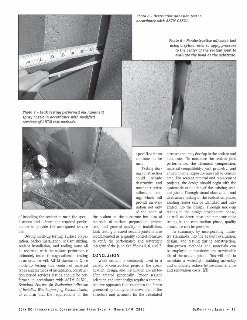
Photo 5 – Destructive adhesion test in accordance with ASTM C1521.
Photo 7 – Leak testing performed via handheld spray nozzle in accordance with modified versions of ASTM test methods.
of installing the sealant to meet the specifications and achieve the required performance to provide the anticipated service life.
During mock-up testing, surface preparation, backer installation, sealant mixing, sealant installation, and tooling must all be reviewed, with the sealant performance ultimately tested through adhesion testing in accordance with aSTm standards. Once mock-up testing has confirmed material types and methods of installation, construction period services testing should be performed in accordance with aSTm C1521, Standard Practice for Evaluating Adhesion of Installed Weatherproofing Sealant Joints, to confirm that the requirements of the
specif ications continue to be met.
Testing during construction could include destructive and nondestructive adhesion testing, which will provide an evaluation not only of the bond of
the sealant at the substrate but also of methods of surface preparation, primer use, and general quality of installation. leak testing of cured sealant joints is also recommended as a quality control measure to verify the performance and watertight integrity of the joint. See Photos 5, 6, and 7.
CONCLUSION While sealant is commonly used in a
variety of construction projects, the specification, design, and installation are all too often treated generically. Proper sealant selection and joint design require a comprehensive approach that examines the forces generated by the dynamic movement of the structure and accounts for the calculated
Photo 6 – Nondestructive adhesion test using a spline roller to apply pressure
to the center of the sealant joint to evaluate the bond at the substrate.
stresses that may develop in the sealant and substrates. To maximize the sealant joint performance, the chemical composition, material compatibility, joint geometry, and environmental exposure must all be considered. For sealant removal and replacement projects, the design should begin with the systematic evaluation of the existing sealant joints. Through visual observation and destructive testing in the evaluation phase, existing issues can be identified and integrated into the design. Through mock-up testing in the design development phase, as well as destructive and nondestructive testing in the construction phase, quality assurance can be provided.
in summary, by incorporating indus try standards into the sealant evaluation, design, and testing during construction, time-proven methods and materials can be employed to maximize the serviceable life of the sealant joints. This will help to maintain a watertight building assembly and ultimately reduce future maintenance and renovation costs.
3 0 t h R C I I n t e R n a t I o n a l C o n v e n t I o n a n d t R a d e S h o w • M a R C h 5 - 1 0 , 2 0 1 5 d a C o S t a a n d l e w I S • 1 7