selection guide… · for securing either timber or steel bearers, and ... the intent of building...
TRANSCRIPT

Uni-PierSelection Guide2013

2 | Uni-Pier Selection Guide
February 2013 www.unipier.com.au
Product Selection GuideUni-Piers are a smart but simple piering system and designed to replace brick piers, concrete or timber stumps that in the past have been traditionally used as sub-floor supports.
Uni-Piers are a two part system each being prefabricated units comprising:- • a “head” that has a built-in ant cap and a cleat
for securing either timber or steel bearers, and
• a square tubular steel (SHS) post to which is welded a base plate that is anchored to the concrete footing or pad.
The final stage of the manufacturing process is hot dip galvanising of the units for life-long durability making them suitable to be used in coastal environments.
When assembled, the piers are adjustable to the desired height, so eliminating inaccuracies that are often evident in concrete footings or pads.
Once positioned and the height determined, the Uni-Pier head and post are normally secured with a number of 14-20x22 to AS 3566 Class 4 self drilling and tapping screws in accordance with the design requirement (refer page 14).
Uni-Piers are non-combustible and will not rot, warp, shrink or harbour termites.
Uni-Piers are designed to suit any normal domestic floor design and are able to support most roof and wall loads in all wind areas and are suitable for up to 5m fall in terrain.
Uni-Piers comply with BCA and relevant Australian Building codes.
To Determine the Pier HeightUni-Piers are supplied in incremental lengths of 200mm.
For Builders Grade piers (65 x 65) the length range is 200mm to 4000mm.
For Heavy duty piers (75 x 75) the length range is 200mm to 5000mm.
Base Plate to Top of Footing DetailTo determine the height of the piers required; establish the distance from the top of each footing to the underside of each bearer then select the post to the nearest 200mm BelOW the dimension.
ExampleMeasured height – 675mm = 600mm Uni-PierMeasured height – 725mm = 600mm Uni-PierMeasured height – 1730mm = 1600mm Uni-Pier
Base Plate Cast into Footing DetailTo determine the height of Uni Piers required in this application, the depth of footing needs to be taken into account, allowing a MINIMUM of 150mm cover UNDeRNeATH the bottom of the Uni-Pier baseplate. Actual embedment of the pier into concrete should be a MINIMUM of 300mm.
Such footings must be designed by a suitably qualified engineer.
For both applications, see diagrams on page 15.
Steps for Selecting Piers
1 Determine wind classification from Wind Region Map of Australia on page 3, or use recommended wind classification provided by a registered engineer.
2 Refer to Wind Classification System table on page 3 and apply selected region (eg A), then select the Topographic Category that best fits the topographic description (eg T1), then choose the terrain category (TC) as indicated in the legend, then determine the amount of shielding to the site, then finally select the wind classification (eg N2).
3 Determine pier height (as described) and bracing requirement on pages 4 and 5.
Note: Bracing may not be required where the base of a building is built with masonry walls.
4 Proceed to relevant page for Uni-Pier load Capacity tables (ie Builders Grade piers or Heavy Grade piers for wind classifications.
Builders Grade for N1, N2 & N3 - pages 6&7Heavy Grade for N1, N2 & N3 - pages 8&9Builders Grade for C1 & C2 - pages 10&11Heavy Grade for C1 & C2 - pages 12&13
Follow instructions under “USING THIS SPeCIFICATION” of each section to determine pier locations and ensure correct types are chosen.
For details of fixing heads to posts and securing posts to footings, refer to Connection Tables and Details on pages 14 and 15.
5

Uni-Pier Selection Guide | 3
www.unipier.com.au February 2013
Wind Region Map of Australia
The intent of building construction, particularly in high wind areas, is to ensure the structure can transfer wind forces to the ground with an adequate margin of safety and to prevent the building from (a) collapsing, (b) being lifted, or, (c) sliding off its foundations.
To resist these forces, the following is necessary:
• An effective anchorage system, where the roof is connected by the walls to the footings by a series of connections; and
• A bracing system to prevent horizontal collapse due to wind forces; and
• Continuity of the system where each structural element is interlocked to its adjoining structural element.
Notes.
Regions are marked A, B, C and D. Coastal region boundaries are smooth lines set to form a smoothed coastline by 50, 100, 150 and 200km. Islands within 50km of the coast are the same region as the adjacent coast. High wind areas also exist outside the wind regions indicated on the above map. Uni-Pier Australia Pty ltd advise that verification be sought from a structural engineer or local council.
Region C
Region C
Region CRegion D
Region C
Region B
Region BRegion B
Region A
Region A
Wind Classification System - from wind region map and site conditions
Wind class
Windregion
(from map)TC
Topographic classT1 T2 T3 T4 T5
Flat areas, slopes less than 1:10, lower third of any hill, middle third of hill less than 1:5
Sloping ground greater than 1:5 and less than 1:3
Sloping ground greater than 1:3
Top of slope less than 1:3
Top of steep hill greater than 1:3
FS PS NS FS PS NS FS PS NS FS PS NS FS PS NS
A 3 N1 N1 N1 N2 N2 N2 N2 N3 N3 N2 N3 N3 N3 N3 N42.5 N1 N1 N2 N2 N3 N3 N2 N3 N3 N3 N3 N4 N3 N4 N42 N1 N2 N2 N2 N3 N3 N3 N3 N3 N3 N4 N4 N4 N4 N41 N2 N3 N3 N3 N3 N4 N3 N4 N4 N4 N4 N4 N4 N5 N5
B 3 N2 N2 N3 N3 N3 N4 N3 N4 N4 N4 N4 N4 N4 N5 N52.5 N2 N3 N3 N3 N4 N4 N3 N4 N4 N4 N4 N5 N4 N5 N52 N2 N3 N3 N3 N4 N4 N4 N4 N5 N4 N5 N5 N5 N5 N61 N3 N4 N4 N4 N5 N5 N4 N5 N5 N5 N5 N6 N5 N6 N6
C 3 C1 C1 C2 C2 C2 C3 C2 C3 C3 C3 C3 C3 C3 C4 C42.5 C1 C2 C2 C2 C3 C3 C3 C3 C3 C3 C4 C4 C4 C4 N/A1,2 C2 C2 C2 C2 C3 C3 C3 C4 C4 C3 C4 C4 C4 N/A N/A
D 3 C2 C3 C3 C3 C4 C4 C3 C4 C4 C4 N/A N/A N/A N/A N/A2.5 C2 C3 C3 C3 C4 C4 C4 N/A N/A C4 N/A N/A N/A N/A N/A1,2 C3 C3 C4 C4 N/A N/A C4 N/A N/A N/A N/A N/A N/A N/A N/A
Notes describing Topographic Class are a guide only. Site specific advice should be sought from a structural engineer.
Important Note. Uni-Pier products are designed for general construction (ie residential). Uni-Pier Australia Pty Ltd recommend that advice be sought from a structural engineer especially when wind zones would typically include N6, C3 and C4.
LegendFS = full shieldingPS = partial shieldingNS = no shieldingN = non-cyclonicC = cyclonicN/A = not applicable - beyond the scope
of Uni-Pier designTC = terrain category
Terrain Category (this a guide only of category classification that surroundsor is likely to surround the site with 5 years)
3 Level wooded country, suburban buildings
2.5 Lightly wooded, long grass (600mm), some buildings
2 Rough, open water surfaces, isolated trees
1 Flat natural surface

4 | Uni-Pier Selection Guide
February 2013 www.unipier.com.au
Cross bracing must be used between Uni-Piers in both directions of the pier’s grid pattern, with each direction being designed separately.
For this application of bracing, 50 x 50 x 2.5mm Duragal angle is recommended. The bracing is typically connected to Uni-Piers with two Self-drilling and tapping screws (14 – 20x22 to AS3566 Class 4) at each end and located no more than 20mm from the top or bottom of the Uni-Pier. The intersection of the braces is fixed together with one screw.
It is important that bracing shown on elevation 1 (below) resists wind loads from Direction 2; and elevation 2 resists wind loads from Direction 1.
The tables contain herein apply for cross bracing between steel Uni-Piers up to 3.6m in height for single storey houses.
ELEVATION 1
Area 1 is shaded 3 bracing sets shown
PLAN
ELEVATION 2
Area 2 is shaded2 bracing sets shown
Sub Floor Bracing using 50 x 50 x2.5mm DURAGAL angle
Steps for Selection
Find Areas Calculate Area 1 and Area 2 (as indicated), being length x height.
If a house is l shaped, divide it into two separate blocks and calculate the wind loading on each block.
Calculate Racking Forces at Floor Level For elevation 1 and then for elevation 2 determine the Racking Force by applying the formula according to the required Wind Area Classification.
Determine the Number of Bracing Sets required By referring to the Table for Capacity of Duragal Angle (refer table), divide the value as determined by Uni-Pier height and Spacing into the calculated Racking Force for both elevations, as per Step 2.
This will result in the number of bracing sets required.
1
2
3
2
1
Calculation of Racking Forces at Floor Level The table below applies for cross braces between Uni-Piers A = Area of house elevation facing wind in square metres ie width of house x height (including roof height) Calculation Example
1. Assume wind area N2
2. Building area facing wind direction:
3. 16m wide x 4.5m high (wall height plus roof height) = 72m2
4. Calculation from table racking force: 0.96 x 72 = 69.12kN
5. Assume Pier Spacing: 2.0m
6. Assume Pier Height: 1.8m
7. Capacity of each cross brace set (refer below table) = 11.1kN
8. Total number of braces required in sub-floor in direction of wind force:
9. 69.12 divided by 11.1 = 6.2. Use 7 bracing sets.
NB. Bracing for use in N5 (C1) wind classification should be determined by a suitably qualified engineer.
Table for Capacity of Duragal angle 50 x 50 x 2.5mm Racking force capacity for each set of cross braces (kN)
Note. Bracing is not required in many situations where the base of a building is built with masonry walls.
2.0m 13.6 11.1 8.9 7.3 3.0m 14.4 12.8 11.1 9.6 4.0m 14.6 13.7 12.4 11.6 4.8m 14.8 14.1 13.2 12.1
Bui
ldin
g H
eigh
tP
ier
Hei
ght
Wind Area Ultimate Limit Racking Force Classification State Velocity Formula AS 4055 m/sec kN
N1 34 0.83 x A N2 40 0.96 x A N3 50 1.80 x A N4 61 2.64 x A
Pier Spacing in direction of brace (m)
Pier Height (m)
0.9m 1.8m 2.7m 3.6m

Uni-Pier Selection Guide | 5
www.unipier.com.au February 2013
Uni-Pier has now developed a bracing system that is pre-assembled, convenient, easy to adjust on site and requires no cutting. The only tools required for installation are a power drill with driver bits capable of installing 14-20x22 self-drilling and tapping screws into steel and clamps to hold the assembly in position during installation.
Further information including installation recommendations, can be found in the Uni-Brace© brochure downloaded from www.unipier.com.au, or available from your Uni-Pier supplier.
The tables below apply to Uni-Brace being installed sub-floor between Uni-Piers to a maximum height of 3.6m and for single storey houses. Uni-Braces© are available in four nominal sizes from 900mm to 1800mm.
Sub Floor Bracing using Uni-Brace©
Uni-Brace© Quantity TableThe following table is to determine the number of Uni-Braces© required on each grid, assuming a single storey house and a maximum roof pitch of 35 degrees. ensure that correct wind classification is applied.
* If unsure of wind classification consult a registered structural engineer. NB: Bracing of Uni-Piers is not required in many situations where the base of a building is built with masonry walls.
UBR9 UBR12 UBR15 UBR18
Nominal Supplied length 900mm 1200mm 1500mm 1800mm
Minimum extension 1640mm 1940mm 2240mm 2540mm
Maximum extension 2100mm 3300mm 4500mm 5700mm
Pier Spacing Grid Wind Class* Wind Class* Wind Class* Wind Class* Maximum N1 N2 N3 N4
2.0m 1 Uni-Brace© every 1 Uni-Brace© every 1 Uni-Brace© every 1 Uni-Brace© every 2nd row 2nd row row row
3.0m 1 Uni-Brace© every 1 Uni-Brace© every 1 Uni-Brace© every 2 Uni-Braces© every 2nd row row row row
4.0m 1 Uni-Brace© every 1 Uni-Brace© every 2 Uni-Braces© every 2 Uni-Braces© every row row row row
4.8m 1 Uni-Brace© every 2 Uni-Braces© every 2 Uni-Braces© every 3 Uni-Braces© every row row row row
1.2 1.5 1.8 2.1 2.4 2.7 3.0 3.3 3.6 3.9 4.2 4.5 4.8
0.6 N/A N/A UBR9 UBR12 UBR12 UBR12 UBR12 UBR15 UBR15 UBR15 UBR15 UBR15 UBR18
0.9 N/A UBR9 UBR9 UBR12 UBR12 UBR12 UBR12 UBR15 UBR15 UBR15 UBR15 UBR18 UBR18
1.2 UBR9 UBR9 UBR12 UBR12 UBR12 UBR12 UBR12 UBR15 UBR15 UBR15 UBR15 UBR18 UBR18
1.5 UBR9 UBR9 UBR12 UBR12 UBR12 UBR12 UBR15 UBR15 UBR15 UBR15 UBR15 UBR18 UBR18
1.8 UBR12 UBR12 UBR12 UBR12 UBR12 UBR12 UBR15 UBR15 UBR15 UBR15 UBR18 UBR18 UBR18
2.1 UBR12 UBR12 UBR12 UBR12 UBR12 UBR15 UBR15 UBR15 UBR15 UBR15 UBR18 UBR18 UBR18
2.4 UBR12 UBR12 UBR12 UBR12 UBR15 UBR15 UBR15 UBR15 UBR15 UBR15 UBR18 UBR18 UBR18
2.7 UBR12 UBR12 UBR12 UBR15 UBR15 UBR15 UBR15 UBR15 UBR15 UBR18 UBR18 UBR18 UBR18
3.0 UBR12 UBR15 UBR15 UBR15 UBR15 UBR15 UBR15 UBR15 UBR18 UBR18 UBR18 UBR18 UBR18
3.3 UBR15 UBR15 UBR15 UBR15 UBR15 UBR15 UBR15 UBR18 UBR18 UBR18 UBR18 UBR18 N/A
3.6 UBR15 UBR15 UBR15 UBR15 UBR15 UBR15 UBR18 UBR18 UBR18 UBR18 UBR18 N/A N/A
MAX
IMUM
POS
T HE
IGHT
MAXIMUM POST SPACING (GRID)
Uni-Brace© Selection TableTo further assist selection, the following table can also be used as a guide to determine Uni-Brace© size requirements. This table assumes that posts to be braced are on level ground and are the same height.
Allow to overlap post. Refer to Step 1.

6 | Uni-Pier Selection Guide
February 2013 www.unipier.com.au
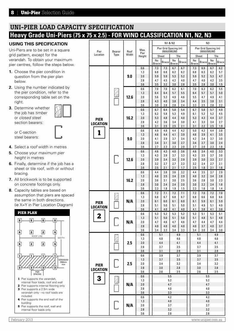
USING THIS SPECIFICATIONUni-Piers are to be set in a square grid pattern, except for the verandah. To obtain your maximum pier centres, follow the steps below.
1. Choose the pier condition in question from the pier plan below.
2. Using the number indicated by the pier condition, refer to the corresponding table set on the right.
3. Determine whetherthe job has timberor closed steelsection bearers:
or C-section steel bearers:
4. Select a roof width in metres
5. Choose your maximum pier height in metres
6. Finally, determine if the job has a sheet or tile roof, with or without bracing.
7. All brickwork is to be supported on concrete footings only.
8. Capacity tables are based on assumption that piers are spaced the same in both directions. (ie X=Y in Pier location Diagram)
PIER PLAN
1 Pier supports the verandah, internal floor loads, roof and wall
2 Pier supports internal flooring only3 Pier supports a 2.5m wide
verandah only - no roof loads are included
4 Pier supports the end wall of the building
5 Pier supports the roof, wall and internal floor loads only
WIDTH
VERANDAH2500mm
max
PIERSPACING
ROOF lINe
5
4
4
5
2
2
5
2
2
5
4
4
1 1
3 3
1
33
1
UNI-PIER LOAD CAPACITY SPECIFICATIONBuilder’s Grade Uni-Piers (65 x 65 x 2) - FOR WIND CLASSIFICATION N1, N2, N3
PierLocation
Bearer Type
Roof Width
Max. Pier
Height
N1 & N2 N3
Pier Grid Spacing (m) (MAXIMUM)
Pier Grid Spacing (m) (MAXIMUM)
Sheet Tile Sheet TileNo
Brace Brace No Brace Brace No
Brace Brace No Brace Brace
PIERLOCATION
1
9.0
0.6 5.4 5.4 4.9 4.9 5.4 4.7 4.9 4.21.3 4.9 5.2 4.4 4.4 4.9 4.1 4.4 3.72.0 4.0 4.1 3.5 3.5 4.0 3.2 3.5 2.92.8 3.0 2.9 2.6 2.5 3.0 2.2 2.6 2.03.6 2.2 2.0 1.8 1.7 2.2 1.6 1.8 1.4
12.6
0.6 5.1 5.4 4.4 4.5 5.1 4.3 4.4 3.71.3 4.6 4.7 4.0 4.0 4.6 3.7 4.0 3.22.0 3.7 3.7 3.1 3.1 3.7 2.9 3.1 2.52.8 2.7 2.6 2.3 2.1 2.7 2.0 2.3 1.73.6 2.0 1.8 1.6 1.4 2.0 1.4 1.6 1.2
16.2
0.6 4.8 4.9 4.0 4.0 4.8 3.9 4.0 3.31.3 4.3 4.3 3.6 3.5 4.3 3.4 3.6 2.92.0 3.5 3.4 2.9 2.7 3.5 2.6 2.9 2.22.8 2.5 2.3 2.0 1.9 2.5 1.8 2.0 1.53.6 1.8 1.6 1.4 1.3 1.8 1.2 1.4 1.0
9.0
0.6 3.7 3.7 3.2 3.2 3.7 3.0 3.2 2.61.3 3.4 3.4 3.0 2.9 3.4 2.7 3.0 2.32.0 2.9 2.8 2.5 2.4 2.9 2.2 2.5 1.92.8 2.2 2.1 1.9 1.8 2.2 1.7 1.9 1.43.6 1.7 1.6 1.5 1.4 1.7 1.2 1.5 1.0
12.6
0.6 3.4 3.4 2.9 2.8 3.4 2.6 2.9 2.31.3 3.1 3.0 2.6 2.5 3.1 2.3 2.6 2.02.0 2.7 2.5 2.2 2.1 2.7 2.0 2.2 1.72.8 2.0 1.9 1.7 1.5 2.0 1.4 1.7 1.23.6 1.6 1.4 1.3 1.1 1.6 1.1 1.3 0.9
16.2
0.6 3.2 3.1 2.6 2.5 3.2 2.4 2.6 2.01.3 2.9 2.7 2.3 2.2 2.9 2.1 2.3 1.82.0 2.4 2.3 2.0 1.8 2.4 1.8 2.0 1.52.8 1.9 1.7 1.5 1.3 1.9 1.3 1.5 1.13.6 1.4 1.2 1.1 1.0 1.4 1.0 1.1 0.8
PIERLOCATION
2
N/A
0.6 5.9 5.6 5.9 5.6 5.9 5.5 5.9 5.51.3 5.5 5.2 5.5 5.2 5.5 5.0 5.5 5.02.0 4.8 4.4 4.8 4.4 4.8 4.2 4.8 4.22.8 4.0 3.5 4.0 3.5 4.0 3.2 4.0 3.23.6 3.2 2.7 3.2 2.7 3.2 2.4 3.2 2.4
N/A
0.6 4.6 4.2 4.6 4.2 4.6 4.0 4.6 4.01.3 4.3 3.9 4.3 3.9 4.3 3.6 4.3 3.62.0 3.9 3.5 3.9 3.5 3.9 3.2 3.9 3.22.8 3.3 2.8 3.3 2.8 3.3 2.5 3.3 2.53.6 2.8 2.2 2.8 2.2 2.8 1.8 2.8 1.8
PIERLOCATION
3
2.5
0.6 4.1 3.9 4.1 3.91.3 3.8 3.6 3.8 3.62.0 3.3 3.2 3.3 3.22.8 2.7 2.6 2.7 2.63.6 2.2 2.1 2.2 2.1
2.5
0.6 3.2 3.0 3.2 3.01.3 2.9 2.8 2.9 2.82.0 2.7 2.5 2.7 2.52.8 2.2 2.2 2.2 2.23.6 1.9 1.9 1.9 1.9
N/A
0.6 4.4 4.41.3 4.1 4.12.0 3.6 3.62.8 2.9 2.93.6 2.4 2.4
N/A
0.6 3.4 3.41.3 3.2 3.22.0 2.9 2.92.8 2.5 2.53.6 2.1 2.1

Uni-Pier Selection Guide | 7
www.unipier.com.au February 2013
USING THIS SPECIFICATIONUni-Piers are to be set in a square grid pattern, except for the verandah. To obtain your maximum pier centres, follow the steps below.
1. Choose the pier condition in question from the pier plan below.
2. Using the number indicated by the pier condition, refer to the corresponding table set on the left.
3. Determine whetherthe job has timberor closed steelsection bearers:
or C-section steel bearers:
4. Select a roof width in metres
5. Choose your maximum pier height in metres
6. Finally, determine if the job has a sheet or tile roof, with or without bracing.
7. All brickwork is to be supported on concrete footings only.
8. Capacity tables are based on assumption that piers are spaced the same in both directions. (ie X=Y in Pier location Diagram)
PIER PLAN
1 Pier supports the verandah, internal floor loads, roof and wall
2 Pier supports internal flooring only3 Pier supports a 2.5m wide
verandah only - no roof loads are included
4 Pier supports the end wall of the building
5 Pier supports the roof, wall and internal floor loads only
WIDTH
VERANDAH2500mm
max
PIERSPACING
ROOF lINe
5
4
4
5
2
2
2
5
4
1 1
3 3
1
33
1
UNI-PIER LOAD CAPACITY SPECIFICATIONBuilder’s Grade Uni-Piers (65 x 65 x 2) - FOR WIND CLASSIFICATION N1, N2, N3
PierLocation
Bearer Type
Roof Width
Max. Pier
Height
N1 & N2 N3Pier Grid Spacing (m)
(MAXIMUM)Pier Grid Spacing (m)
(MAXIMUM)
Sheet Tile Sheet Tile
No Brace Brace No
Brace Brace No Brace Brace No
Brace Brace
PIERLOCATION
4
9.0
0.6 8.0 8.0 8.0 8.0 8.0 6.3 8.0 6.31.3 7.3 7.2 7.3 7.2 7.3 5.6 7.3 5.62.0 6.3 5.9 6.3 5.9 6.3 4.5 6.3 4.52.8 5.1 4.3 5.1 4.3 5.1 3.2 5.1 3.23.6 4.1 3.1 4.1 3.1 4.1 2.2 4.1 2.2
12.6
0.6 7.9 7.6 7.9 7.6 7.9 5.9 7.9 5.91.3 7.2 6.8 7.2 6.8 7.2 5.2 7.2 5.22.0 6.2 5.5 6.2 5.5 6.2 4.1 6.2 4.12.8 5.0 4.0 5.0 4.0 5.0 2.9 5.0 2.93.6 4.0 2.9 4.0 2.9 4.0 2.1 4.0 2.1
16.2
0.6 7.8 7.4 7.8 7.4 7.8 5.7 7.8 5.71.3 7.1 6.6 7.1 6.6 7.1 5.0 7.1 5.02.0 6.1 5.3 6.1 5.3 6.1 4.0 6.1 4.02.8 5.0 3.8 5.0 3.8 5.0 2.8 5.0 2.83.6 4.0 2.8 4.0 2.8 4.0 2.0 4.0 2.0
9.0
0.6 6.0 5.4 6.0 5.4 6.0 4.1 6.0 4.11.3 5.6 4.9 5.6 4.9 5.6 3.7 5.6 3.72.0 5.0 4.2 5.0 4.2 5.0 3.1 5.0 3.12.8 4.2 3.2 4.2 3.2 4.2 2.3 4.2 2.33.6 3.6 2.5 3.6 2.5 3.6 1.7 3.6 1.7
12.6
0.6 5.9 5.1 5.9 5.1 5.9 3.8 5.9 3.81.3 5.5 4.6 5.5 4.6 5.5 3.4 5.5 3.42.0 5.0 3.9 5.0 3.9 5.0 2.8 5.0 2.82.8 4.1 3.0 4.1 3.0 4.1 2.1 4.1 2.13.6 3.4 2.3 3.4 2.3 3.4 1.6 3.4 1.6
16.2
0.6 5.8 4.9 5.8 4.9 5.8 3.6 5.8 3.61.3 5.4 4.4 5.4 4.4 5.4 3.2 5.4 3.22.0 4.9 3.7 4.9 3.7 4.9 2.7 4.9 2.72.8 4.1 2.9 4.1 2.9 4.1 2.0 4.1 2.03.6 3.4 2.2 3.4 2.2 3.4 1.5 3.4 1.5
PIERLOCATION
5
9.0
0.6 7.0 6.3 6.2 5.5 7.0 5.1 6.2 4.51.3 6.4 5.6 5.7 4.9 6.5 4.4 5.6 4.02.0 5.4 4.5 4.7 3.9 5.3 3.5 4.5 3.12.8 4.2 3.2 3.6 2.7 3.9 2.5 3.3 2.23.6 3.3 2.3 2.7 1.9 2.9 1.7 2.3 1.5
12.6
0.6 6.6 5.7 5.6 4.8 6.4 4.5 5.3 4.01.3 6.0 5.1 5.1 4.2 5.7 4.0 4.7 3.42.0 5.0 4.0 4.1 3.3 4.6 3.1 3.7 2.72.8 3.9 2.9 3.1 2.3 3.3 2.2 2.6 1.83.6 3.0 2.0 2.2 1.6 2.4 1.5 1.9 1.3
16.2
0.6 6.1 5.2 5.1 4.3 5.7 4.1 4.6 3.51.3 5.6 4.6 4.6 3.7 5.0 3.6 4.0 3.02.0 4.6 3.7 3.6 2.9 4.0 2.8 3.1 2.32.8 3.5 2.6 2.6 2.0 2.9 2.0 2.2 1.63.6 2.5 1.8 1.8 1.4 2.0 1.3 1.5 1.1
9.0
0.6 5.1 4.1 4.4 3.5 4.9 3.2 4.0 2.81.3 4.7 3.7 4.0 3.2 4.5 2.9 3.7 2.52.0 4.2 3.1 3.5 2.7 3.8 2.4 3.2 2.12.8 3.4 2.4 2.8 2.0 3.0 1.8 2.4 1.63.6 2.8 1.8 2.2 1.5 2.3 1.4 1.8 1.2
12.6
0.6 4.7 3.7 3.9 3.0 4.2 2.9 3.4 2.41.3 4.3 3.3 3.5 2.7 3.8 2.5 3.1 2.22.0 3.8 2.8 3.0 2.3 3.2 2.1 2.6 1.82.8 3.0 2.1 2.3 1.7 2.5 1.6 2.0 1.43.6 2.3 1.6 1.7 1.3 1.9 1.2 1.5 1.0
16.2
0.6 4.4 3.3 3.3 2.7 3.6 2.6 2.9 2.11.3 4.0 3.0 3.0 2.4 3.3 2.3 2.6 1.92.0 3.4 2.5 2.5 2.0 2.7 1.9 2.2 1.62.8 2.6 1.9 1.9 1.5 2.1 1.4 1.6 1.13.6 2.0 1.4 1.4 1.1 1.6 1.0 1.2 0.9
5
4
2
8 | Uni-Pier Selection Guide
February 2013 www.unipier.com.au
USING THIS SPECIFICATIONUni-Piers are to be set in a square grid pattern, except for the verandah. To obtain your maximum pier centres, follow the steps below.
1. Choose the pier condition in question from the pier plan below.
2. Using the number indicated by the pier condition, refer to the corresponding table set on the right.
3. Determine whetherthe job has timberor closed steelsection bearers:
or C-section steel bearers:
4. Select a roof width in metres
5. Choose your maximum pier height in metres
6. Finally, determine if the job has a sheet or tile roof, with or without bracing.
7. All brickwork is to be supported on concrete footings only.
8. Capacity tables are based on assumption that piers are spaced the same in both directions. (ie X=Y in Pier location Diagram)
PIER PLAN
1 Pier supports the verandah, internal floor loads, roof and wall
2 Pier supports internal flooring only3 Pier supports a 2.5m wide
verandah only - no roof loads are included
4 Pier supports the end wall of the building
5 Pier supports the roof, wall and internal floor loads only
WIDTH
VERANDAH2500mm
max
PIERSPACING
ROOF lINe
5
4
4
5
2
2
5
2
2
5
4
4
1 1
3 3
1
33
1
UNI-PIER LOAD CAPACITY SPECIFICATIONHeavy Grade Uni-Piers (75 x 75 x 2.5) - FOR WIND CLASSIFICATION N1, N2, N3
PierLocation
Bearer Type
Roof Width
Max. Pier
Height
N1 & N2 N3
Pier Grid Spacing (m) (MAXIMUM)
Pier Grid Spacing (m) (MAXIMUM)
Sheet Tile Sheet TileNo
Brace Brace No Brace Brace No
Brace Brace No Brace Brace
PIERLOCATION
1
9.0
0.6 7.3 7.3 6.7 6.7 7.3 6.9 6.7 6.21.3 6.8 6.8 6.2 6.2 6.8 6.3 6.2 5.72.0 5.9 5.9 5.3 5.2 5.9 5.2 5.3 4.72.8 4.7 4.5 4.2 4.0 4.7 4.0 4.2 3.53.6 3.5 3.2 3.0 2.8 3.5 2.8 3.0 1.5
12.6
0.6 7.0 7.0 6.2 6.1 7.0 6.3 6.2 5.51.3 6.4 6.4 5.7 5.5 6.4 5.7 5.7 5.02.0 5.6 5.3 4.9 4.6 5.5 4.7 4.9 4.12.8 4.3 4.0 3.8 3.4 4.4 3.5 3.8 3.13.6 3.0 2.8 2.8 2.4 3.3 2.5 2.8 2.2
16.2
0.6 6.7 6.4 5.8 5.4 6.7 5.8 5.7 4.91.3 6.2 5.8 5.3 4.9 6.1 5.2 5.2 4.52.0 5.3 4.8 4.4 4.0 5.3 4.3 4.4 3.72.8 4.2 3.6 3.4 3.0 4.1 3.3 3.4 2.73.6 3.1 2.5 2.5 2.1 3.1 2.2 2.5 1.9
9.0
0.6 4.9 4.8 4.4 4.2 5.0 4.2 4.4 3.81.3 4.6 4.4 4.1 3.9 4.6 3.9 4.1 3.52.0 4.1 3.9 3.7 3.4 4.2 3.4 3.7 3.02.8 3.4 3.1 3.0 2.7 3.4 2.7 3.0 2.43.6 2.7 2.3 2.3 2.0 2.7 2.0 2.3 1.8
12.6
0.6 4.6 4.3 4.0 3.6 4.6 3.4 4.0 3.31.3 4.3 3.9 3.7 3.3 4.3 3.5 3.7 3.02.0 3.9 3.4 3.3 2.9 3.9 3.0 3.3 2.72.8 3.2 2.7 2.7 2.3 3.2 2.4 2.7 2.13.6 2.5 2.1 2.1 1.7 2.5 1.8 2.1 1.6
16.2
0.6 4.4 3.8 3.6 3.2 4.4 3.5 3.7 2.91.3 4.0 3.5 3.4 2.9 4.0 3.2 3.4 2.82.0 3.6 3.1 3.0 2.5 3.6 2.8 3.0 2.32.8 3.0 2.4 2.4 2.0 3.0 2.2 2.4 1.83.6 2.3 1.8 1.9 1.5 2.3 1.6 1.8 1.4
PIERLOCATION
2
N/A
0.6 7.2 7.1 7.2 7.1 7.2 7.0 7.2 7.01.3 6.8 6.7 6.8 6.7 6.8 6.6 6.8 6.62.0 6.1 6.0 6.1 6.0 6.1 5.9 6.1 5.92.8 5.1 5.0 5.1 5.0 5.1 4.9 5.1 4.93.6 4.1 4.0 4.1 4.0 4.1 3.8 4.1 3.8
N/A
0.6 5.3 5.2 5.3 5.2 5.3 5.1 5.3 5.11.3 5.1 5.0 5.1 5.0 5.1 4.8 5.1 4.82.0 4.7 4.6 4.7 4.6 4.7 4.4 4.7 4.42.8 4.0 4.0 4.0 4.0 4.0 3.7 4.0 3.73.6 3.4 3.3 3.4 3.3 3.4 3.0 3.4 3.0
PIERLOCATION
3
2.5
0.6 5.1 4.9 5.1 4.91.3 4.8 4.6 4.8 4.62.0 4.4 4.1 4.4 4.12.8 3.7 3.5 3.7 3.53.6 3.1 2.9 3.1 2.9
2.5
0.6 3.9 3.7 3.9 3.71.3 3.7 3.5 3.7 3.52.0 3.4 3.2 3.4 3.22.8 3.0 2.8 3.0 2.83.6 2.6 2.5 2.6 2.5
N/A
0.6 5.5 5.51.3 5.2 5.22.0 4.7 4.72.8 4.0 4.03.6 3.3 3.3
N/A
0.6 4.2 4.21.3 4.0 4.02.0 3.7 3.72.8 3.2 3.23.6 2.8 2.8

Uni-Pier Selection Guide | 9
www.unipier.com.au February 2013
USING THIS SPECIFICATIONUni-Piers are to be set in a square grid pattern, except for the verandah. To obtain your maximum pier centres, follow the steps below.
1. Choose the pier condition in question from the pier plan below.
2. Using the number indicated by the pier condition, refer to the corresponding table set on the left.
3. Determine whetherthe job has timberor closed steelsection bearers:
or C-section steel bearers:
4. Select a roof width in metres
5. Choose your maximum pier height in metres
6. Finally, determine if the job has a sheet or tile roof, with or without bracing.
7. All brickwork is to be supported on concrete footings only.
8. Capacity tables are based on assumption that piers are spaced the same in both directions. (ie X=Y in Pier location Diagram)
PIER PLAN
1 Pier supports the verandah, internal floor loads, roof and wall
2 Pier supports internal flooring only3 Pier supports a 2.5m wide
verandah only - no roof loads are included
4 Pier supports the end wall of the building
5 Pier supports the roof, wall and internal floor loads only
WIDTH
VERANDAH2500mm
max
PIERSPACING
ROOF lINe
5
4
4
5
2
2
2
5
4
1 1
3 3
1
33
1
UNI-PIER LOAD CAPACITY SPECIFICATIONHeavy Grade Uni-Piers (75 x 75 x 2.5) - FOR WIND CLASSIFICATION N1, N2, N3
PierLocation
Bearer Type
Roof Width
Max. Pier
Height
N1 & N2 N3Pier Grid Spacing (m)
(MAXIMUM)Pier Grid Spacing (m)
(MAXIMUM)
Sheet Tile Sheet Tile
No Brace Brace No
Brace Brace No Brace Brace No
Brace Brace
PIERLOCATION
4
9.0
0.6 10.0 10.0 10.0 10.0 10.0 8.9 10.0 8.91.3 9.4 9.4 9.4 9.4 9.4 8.2 9.4 8.22.0 8.4 8.4 8.4 8.4 8.4 6.9 8.4 6.92.8 7.1 6.9 7.1 6.9 7.1 5.4 7.1 5.43.6 5.8 5.2 5.8 5.2 5.8 3.9 5.8 3.9
12.6
0.6 9.9 9.9 9.9 9.9 9.9 8.4 9.9 8.41.3 9.3 9.3 9.3 9.3 9.3 7.7 9.3 7.72.0 8.3 8.3 8.3 8.3 8.3 6.5 8.3 6.52.8 7.0 6.5 7.0 6.5 7.0 5.0 7.0 5.03.6 5.7 4.8 5.7 4.8 5.7 3.6 5.7 3.6
16.2
0.6 9.8 9.8 9.8 9.8 9.8 8.1 9.8 8.11.3 9.2 9.2 9.2 9.2 9.2 7.4 9.2 7.42.0 8.2 8.0 8.2 8.0 8.2 6.2 8.2 6.22.8 6.9 6.3 6.9 6.3 6.9 4.8 6.9 4.83.6 5.6 4.6 5.6 4.6 5.6 3.4 5.6 3.4
9.0
0.6 7.4 7.3 7.4 7.3 7.4 5.7 7.4 5.71.3 7.0 6.8 7.0 6.8 7.0 5.2 7.0 5.22.0 6.5 6.1 6.5 6.1 6.5 4.7 6.5 4.72.8 5.6 5.0 5.6 5.0 5.6 3.7 5.6 3.73.6 4.7 3.9 4.7 3.9 4.7 2.9 4.7 2.9
12.6
0.6 7.3 6.9 7.3 6.9 7.3 5.3 7.3 5.31.3 6.9 6.4 6.9 6.4 6.9 4.9 6.9 4.92.0 6.4 5.7 6.4 5.7 6.4 4.3 6.4 4.32.8 5.6 4.7 5.6 4.7 5.6 3.4 5.6 3.43.6 4.7 3.7 4.7 3.7 4.7 2.6 4.7 2.6
16.2
0.6 7.2 6.6 7.2 6.6 7.2 5.1 7.2 5.11.3 6.8 6.2 6.8 6.2 6.8 4.7 6.8 4.72.0 6.3 5.5 6.3 5.5 6.3 4.1 6.3 4.12.8 5.5 4.5 5.5 4.5 5.5 3.3 5.5 3.33.6 4.6 3.5 4.6 3.5 4.6 2.5 4.6 2.5
PIERLOCATION
5
9.0
0.6 9.0 8.7 8.2 7.8 9.0 7.2 8.2 6.51.3 8.4 8.0 7.7 7.2 8.5 6.6 7.7 6.02.0 7.5 6.9 6.7 6.1 7.5 5.6 6.9 5.02.8 6.2 5.4 5.5 4.7 6.2 4.2 5.4 3.83.6 4.9 4.0 4.3 3.4 4.7 3.0 4.0 2.7
12.6
0.6 8.6 8.1 7.5 7.0 8.6 6.6 7.5 5.81.3 8.0 7.4 7.0 6.4 8.0 6.0 7.0 5.32.0 7.0 6.3 6.1 5.3 7.0 5.0 5.9 4.42.8 5.8 4.9 4.9 4.1 5.5 3.8 4.5 3.33.6 4.5 3.5 3.7 2.9 4.0 2.7 3.3 2.3
16.2
0.6 8.1 7.5 7.0 6.2 8.0 6.1 6.6 5.21.3 7.6 6.8 6.4 5.7 7.3 5.5 6.0 4.72.0 6.6 5.8 5.5 4.7 6.2 4.6 5.1 3.82.8 5.4 4.4 4.4 3.6 4.8 3.4 3.8 2.93.6 4.2 3.2 3.2 2.5 3.5 2.4 2.7 2.0
9.0
0.6 6.4 5.7 5.7 5.0 6.4 4.5 5.7 4.01.3 6.1 5.2 5.4 4.6 6.0 4.1 5.3 3.72.0 5.6 4.7 4.9 4.0 5.5 3.6 4.7 3.22.8 4.8 3.8 4.1 3.2 4.5 2.9 3.8 2.63.6 4.0 3.0 3.3 2.5 3.6 2.2 3.0 2.0
12.6
0.6 6.0 5.1 5.1 4.3 5.8 4.0 4.8 3.51.3 5.7 4.8 4.8 4.0 5.4 3.7 4.4 3.22.0 5.2 4.2 4.3 3.5 4.8 3.3 3.9 2.82.8 4.4 3.4 3.6 2.8 3.9 2.6 3.1 2.23.6 3.6 2.6 2.8 2.1 3.0 2.0 2.4 1.7
16.2
0.6 5.7 4.7 4.6 3.8 5.1 3.7 4.1 3.11.3 5.3 4.3 4.3 3.5 4.7 3.4 3.7 2.82.0 4.8 3.8 3.8 3.0 4.2 3.0 3.3 2.52.8 4.0 3.0 3.1 2.4 3.4 2.3 2.6 1.93.6 3.3 2.3 2.3 1.8 2.6 1.8 2.0 1.4
5
4
2

10 | Uni-Pier Selection Guide
February 2013 www.unipier.com.au
USING THIS SPECIFICATIONUni-Piers are to be set in a square grid pattern, except for the verandah. To obtain your maximum pier centres, follow the steps below.
1. Choose the pier condition in question from the pier plan below.
2. Using the number indicated by the pier condition, refer to the corresponding table set on the right.
3. Determine whetherthe job has timberor closed steelsection bearers:
or C-section steel bearers:
4. Select a roof width in metres
5. Choose your maximum pier height in metres
6. Finally, determine if the job has a sheet or tile roof, with or without bracing.
7. All brickwork is to be supported on concrete footings only.
8. Capacity tables are based on assumption that piers are spaced the same in both directions. (ie X=Y in Pier location Diagram)
PIER PLAN
1 Pier supports the verandah, internal floor loads, roof and wall
2 Pier supports internal flooring only3 Pier supports a 2.5m wide
verandah only - no roof loads are included
4 Pier supports the end wall of the building
5 Pier supports the roof, wall and internal floor loads only
WIDTH
VERANDAH2500mm
max
PIERSPACING
ROOF lINe
5
4
4
5
2
2
5
2
2
5
4
4
1 1
3 3
1
33
1
UNI-PIER LOAD CAPACITY SPECIFICATIONBuilder’s Grade Uni-Piers (65 x 65 x 2) - FOR WIND CLASSIFICATION C1, C2, N4, N5
PierLocation
Bearer Type
Roof Width
Max. Pier
Height
N4 & C1 N5 & C2
Pier Grid Spacing (m) (MAXIMUM)
Pier Grid Spacing (m) (MAXIMUM)
Sheet Tile Sheet TileNo
Brace Brace No Brace Brace No
Brace Brace No Brace Brace
PIERLOCATION
1
9.0
0.6 5.4 3.7 4.9 3.4 4.9 2.9 4.4 2.71.3 4.9 3.2 4.3 2.9 4.3 2.5 3.8 2.32.0 4.0 2.5 3.6 2.2 3.4 1.9 3.0 1.82.8 2.9 1.7 2.5 1.5 2.3 1.3 2.1 1.23.6 2.0 1.2 1.7 1.0 1.6 0.9 1.4 0.8
12.6
0.6 4.5 3.0 4.3 3.0 4.1 2.6 3.6 2.31.3 3.9 2.6 3.8 2.6 3.6 2.2 3.1 2.02.0 3.1 2.0 3.0 2.0 2.8 1.7 2.4 1.52.8 2.1 1.4 2.0 1.3 1.9 1.2 1.6 1.03.6 1.4 0.9 1.4 0.9 1.3 0.8 1.1 0.7
16.2
0.6 4.4 3.0 3.7 2.6 3.5 2.3 3.0 2.01.3 3.9 2.6 3.2 2.3 3.0 2.0 2.6 1.82.0 3.0 2.0 2.5 1.7 2.3 1.5 2.0 1.32.8 2.1 1.3 1.7 1.2 1.6 1.0 1.3 0.93.6 1.4 0.9 1.1 0.7 1.1 0.7 0.9 0.5
9.0
0.6 3.8 2.2 3.3 2.0 3.1 1.7 2.7 1.61.3 3.4 2.0 2.9 1.8 2.7 1.5 2.4 1.42.0 2.8 1.6 2.4 1.5 2.3 1.3 2.0 1.22.8 2.1 1.2 1.8 1.1 1.7 0.9 1.5 0.83.6 1.6 0.9 1.3 0.8 1.2 0.7 1.1 0.5
12.6
0.6 2.8 1.8 2.7 1.8 2.5 1.5 2.2 1.41.3 2.5 1.6 2.4 1.6 2.2 1.4 1.9 1.22.0 2.0 1.3 2.0 1.3 1.9 1.1 1.6 1.02.8 1.5 1.0 1.4 1.0 1.4 0.8 1.2 0.73.6 1.1 0.7 1.1 0.7 1.0 0.5 0.8 0.5
16.2
0.6 2.7 1.8 2.2 1.6 2.1 1.3 1.8 1.21.3 2.4 1.6 2.0 1.4 1.9 1.2 1.6 1.12.0 2.0 1.3 1.6 1.1 1.5 1.0 1.3 0.92.8 1.5 1.0 1.2 0.8 1.1 0.7 0.9 0.53.6 1.1 0.7 0.9 0.6 0.8 0.5 0.7 0.3
PIERLOCATION
2
N/A
0.6 5.9 5.7 5.9 5.7 5.9 5.6 5.9 5.61.3 5.5 5.3 5.5 5.3 5.5 5.2 5.5 5.22.0 4.8 4.6 4.8 4.6 4.8 4.4 4.8 4.42.8 4.0 3.6 4.0 3.6 4.0 3.5 4.0 3.53.6 3.2 2.9 3.2 2.9 3.2 2.7 3.2 2.7
N/A
0.6 4.6 4.3 4.6 4.3 4.6 4.2 4.6 4.21.3 4.3 4.0 4.3 4.0 4.3 3.9 4.3 3.92.0 3.9 3.6 3.9 3.6 3.9 3.5 3.9 3.52.8 3.3 3.0 3.3 3.0 3.3 2.8 3.3 2.83.6 2.8 2.4 2.8 2.4 2.8 2.2 2.8 2.2
PIERLOCATION
3
2.5
0.6 4.1 3.9 4.1 3.91.3 3.8 3.6 3.8 3.62.0 3.3 3.2 3.3 3.22.8 2.7 2.6 2.7 2.63.6 2.2 2.1 2.2 2.1
2.5
0.6 3.2 3.0 3.2 3.01.3 2.9 2.8 2.9 2.82.0 2.7 2.5 2.7 2.52.8 2.2 2.2 2.2 2.23.6 1.9 1.9 1.9 1.9
N/A
0.6 4.4 4.41.3 4.1 4.12.0 3.6 3.62.8 2.9 2.93.6 2.4 2.4
N/A
0.6 3.4 3.41.3 3.2 3.22.0 2.9 2.92.8 2.5 2.53.6 2.1 2.1

Uni-Pier Selection Guide | 11
www.unipier.com.au February 2013
USING THIS SPECIFICATIONUni-Piers are to be set in a square grid pattern, except for the verandah. To obtain your maximum pier centres, follow the steps below.
1. Choose the pier condition in question from the pier plan below.
2. Using the number indicated by the pier condition, refer to the corresponding table set on the left.
3. Determine whetherthe job has timberor closed steelsection bearers:
or C-section steel bearers:
4. Select a roof width in metres
5. Choose your maximum pier height in metres
6. Finally, determine if the job has a sheet or tile roof, with or without bracing.
7. All brickwork is to be supported on concrete footings only.
8. Capacity tables are based on assumption that piers are spaced the same in both directions. (ie X=Y in Pier location Diagram)
PIER PLAN
1 Pier supports the verandah, internal floor loads, roof and wall
2 Pier supports internal flooring only3 Pier supports a 2.5m wide
verandah only - no roof loads are included
4 Pier supports the end wall of the building
5 Pier supports the roof, wall and internal floor loads only
WIDTH
VERANDAH2500mm
max
PIERSPACING
ROOF lINe
5
4
4
5
2
2
2
5
4
1 1
3 3
1
33
1
UNI-PIER LOAD CAPACITY SPECIFICATIONBuilder’s Grade Uni-Piers (65 x 65 x 2) - FOR WIND CLASSIFICATION C1, C2, N4, N5
PierLocation
Bearer Type
Roof Width
Max. Pier
Height
N4 & C1 N5 & C2
Pier Grid Spacing (m) (MAXIMUM)
Pier Grid Spacing (m) (MAXIMUM)
Sheet Tile Sheet TileNo
Brace Brace No Brace Brace No
Brace Brace No Brace Brace
PIERLOCATION
4
9.0
0.6 8.0 5.6 8.0 5.6 8.0 4.5 8.0 4.51.3 7.3 4.9 7.3 4.9 7.3 3.9 7.3 3.92.0 6.3 3.9 6.3 3.9 6.3 3.0 6.3 3.02.8 5.1 2.7 5.1 2.7 5.1 2.1 5.1 2.13.6 4.1 1.9 4.1 1.9 4.1 1.4 4.1 1.4
12.6
0.6 7.9 5.2 7.9 5.2 7.9 4.1 7.9 4.11.3 7.2 4.6 7.2 4.6 7.2 3.6 7.2 3.62.0 6.2 3.6 6.2 3.6 6.2 2.8 6.2 2.82.8 5.0 2.5 5.0 2.5 5.0 1.9 5.0 1.93.6 4.0 1.7 4.0 1.7 4.0 1.3 4.0 1.3
16.2
0.6 7.8 4.9 7.8 4.9 7.8 3.9 7.8 3.91.3 7.1 4.3 7.1 4.3 7.1 3.4 7.1 3.42.0 6.1 3.4 6.1 3.4 6.1 2.6 6.1 2.62.8 5.0 2.3 5.0 2.3 5.0 1.8 5.0 1.83.6 4.0 1.6 4.0 1.6 4.0 1.2 4.0 1.2
9.0
0.6 6.0 3.6 6.0 3.6 6.0 2.8 6.0 2.81.3 5.6 3.2 5.6 3.2 5.6 2.5 5.6 2.52.0 5.0 2.6 5.0 2.6 5.0 2.0 5.0 2.02.8 4.2 2.0 4.2 2.0 4.2 1.5 4.2 1.53.6 3.6 1.5 3.6 1.5 3.6 1.1 3.6 1.1
12.6
0.6 5.9 3.2 5.9 3.2 5.9 2.5 5.9 2.51.3 5.5 2.9 5.5 2.9 5.5 2.2 5.5 2.22.0 5.0 2.4 5.0 2.4 5.0 1.8 5.0 1.82.8 4.1 1.8 4.1 1.8 4.1 1.4 4.1 1.43.6 3.4 1.4 3.4 1.4 3.4 1.0 3.4 1.0
16.2
0.6 5.8 3.1 5.8 3.1 5.8 2.3 5.8 2.31.3 5.4 2.7 5.4 2.7 5.4 2.1 5.4 2.12.0 4.9 2.3 4.9 2.3 4.9 1.7 4.9 1.72.8 4.1 1.7 4.1 1.7 4.1 1.3 4.1 1.33.6 3.4 1.2 3.4 1.2 3.4 0.9 3.4 0.9
PIERLOCATION
5
9.0
0.6 6.4 4.0 5.6 3.6 5.3 3.5 4.7 3.21.3 5.7 3.4 5.0 3.1 4.6 3.0 4.1 2.82.0 4.6 2.7 4.0 2.4 3.7 2.3 3.2 2.12.8 3.3 1.8 2.8 1.7 2.6 1.6 2.3 1.43.6 2.4 1.3 2.0 1.1 1.8 1.1 1.6 1.0
12.6
0.6 5.5 3.5 4.6 3.1 4.4 3.1 3.8 2.81.3 4.9 3.1 4.1 2.7 3.9 2.7 3.3 2.42.0 3.8 2.4 3.2 2.1 3.0 2.1 2.6 1.92.8 2.7 1.6 2.2 1.4 2.1 1.4 1.8 1.33.6 1.9 1.1 1.6 1.0 1.4 1.0 1.2 0.9
16.2
0.6 4.7 3.2 3.9 2.7 3.7 2.8 3.1 2.51.3 4.1 2.8 3.4 2.4 3.2 2.5 2.7 2.12.0 3.3 2.1 2.6 1.8 2.5 1.9 2.1 1.62.8 2.3 1.4 1.8 1.2 1.7 1.3 1.4 1.13.6 1.6 1.0 1.3 0.8 1.2 0.9 1.0 0.8
9.0
0.6 4.3 2.5 3.7 2.2 3.4 2.1 3.0 1.91.3 3.9 2.2 3.3 2.0 3.0 1.9 2.7 1.72.0 3.3 1.8 2.8 1.6 2.5 1.5 2.2 1.42.8 2.5 1.4 2.1 1.2 1.9 1.1 1.6 1.03.6 1.9 1.0 1.6 0.9 1.4 0.8 1.2 0.7
12.6
0.6 3.6 2.2 2.9 1.9 2.8 1.9 2.3 1.71.3 3.2 1.9 2.6 1.7 2.4 1.7 2.1 1.52.0 2.7 1.6 2.2 1.4 2.0 1.4 1.7 1.22.8 2.0 1.2 1.6 1.0 1.5 1.0 1.3 0.93.6 1.5 0.9 1.2 0.8 1.1 0.7 0.9 0.5
16.2
0.6 3.0 1.9 2.4 1.7 2.3 1.7 1.9 1.51.3 2.7 1.7 2.2 1.5 2.0 1.5 1.7 1.32.0 2.2 1.4 1.8 1.2 1.7 1.2 1.4 1.12.8 1.7 1.0 1.3 0.9 1.2 0.9 1.0 0.83.6 1.2 0.8 1.0 0.7 0.9 0.7 0.7 0.5
5
4
2

12 | Uni-Pier Selection Guide
February 2013 www.unipier.com.au
USING THIS SPECIFICATIONUni-Piers are to be set in a square grid pattern, except for the verandah. To obtain your maximum pier centres, follow the steps below.
1. Choose the pier condition in question from the pier plan below.
2. Using the number indicated by the pier condition, refer to the corresponding table set on the right.
3. Determine whetherthe job has timberor closed steelsection bearers:
or C-section steel bearers:
4. Select a roof width in metres
5. Choose your maximum pier height in metres
6. Finally, determine if the job has a sheet or tile roof, with or without bracing.
7. All brickwork is to be supported on concrete footings only.
8. Capacity tables are based on assumption that piers are spaced the same in both directions. (ie X=Y in Pier location Diagram)
PIER PLAN
1 Pier supports the verandah, internal floor loads, roof and wall
2 Pier supports internal flooring only3 Pier supports a 2.5m wide
verandah only - no roof loads are included
4 Pier supports the end wall of the building
5 Pier supports the roof, wall and internal floor loads only
WIDTH
VERANDAH2500mm
max
PIERSPACING
ROOF lINe
5
4
4
5
2
2
5
2
2
5
4
4
1 1
3 3
1
33
1
UNI-PIER LOAD CAPACITY SPECIFICATIONHeavy Grade Uni-Piers (75 x 75 x 2.5) - FOR WIND CLASSIFICATION C1, C2, N4, N5
PierLocation
Bearer Type
Roof Width
Max. Pier
Height
N4 & C1 N5 & C2
Pier Grid Spacing (m) (MAXIMUM)
Pier Grid Spacing (m) (MAXIMUM)
Sheet Tile Sheet TileNo
Brace Brace No Brace Brace No
Brace Brace No Brace Brace
PIERLOCATION
1
9.0
0.6 7.3 5.5 6.7 5.1 7.2 4.4 6.5 4.11.3 6.8 5.0 6.2 4.6 6.5 4.0 5.9 3.72.0 5.9 4.1 5.3 3.8 5.5 3.2 4.9 3.02.8 4.7 3.1 4.2 2.8 4.1 2.4 3.7 2.23.6 3.5 2.1 3.0 1.9 2.9 1.6 2.6 1.5
12.6
0.6 6.6 4.6 6.2 4.5 6.1 4.0 5.4 3.61.3 6.0 4.1 5.7 4.0 5.5 3.5 4.8 3.22.0 5.0 3.4 4.8 3.3 4.6 2.9 4.0 2.62.8 3.7 2.5 3.6 2.4 3.4 2.1 3.0 1.93.6 2.6 1.7 2.5 1.7 2.4 1.5 2.1 1.3
16.2
0.6 6.5 4.5 5.5 4.0 5.2 3.5 4.5 3.21.3 5.9 4.1 4.9 3.6 4.7 3.1 4.1 2.82.0 4.9 3.3 4.1 2.9 3.9 2.5 3.3 2.32.8 3.7 2.5 3.0 2.1 2.9 1.9 2.5 1.73.6 2.6 1.7 2.1 1.5 2.0 1.3 1.7 1.1
9.0
0.6 4.9 3.3 4.6 3.0 4.4 2.5 3.9 2.31.3 4.6 3.0 4.3 2.7 4.0 2.3 3.6 2.12.0 4.1 2.6 3.7 2.4 3.5 2.0 3.1 1.92.8 3.4 2.0 3.0 1.8 2.8 1.6 2.5 1.43.6 2.7 1.5 2.3 1.4 2.1 1.2 1.9 1.1
12.6
0.6 4.0 2.7 3.8 2.6 3.7 2.3 3.2 2.01.3 3.7 2.4 3.5 2.4 3.3 2.1 2.9 1.92.0 3.2 2.1 3.1 2.1 2.9 1.8 2.5 1.62.8 2.5 1.6 2.4 1.6 2.3 1.4 2.0 1.23.6 1.9 1.2 1.8 1.2 1.7 1.0 1.5 0.9
16.2
0.6 3.9 2.6 3.2 2.3 3.1 2.0 2.7 1.81.3 3.6 2.4 3.0 2.1 2.8 1.8 2.4 1.62.0 3.1 2.1 2.6 1.8 2.4 1.6 2.1 1.42.8 2.5 1.6 2.0 1.4 1.9 1.2 1.6 1.13.6 1.9 1.2 1.5 1.1 1.4 0.9 1.2 0.8
PIERLOCATION
2
N/A
0.6 7.2 6.8 7.2 6.8 7.2 6.6 7.2 6.61.3 6.8 6.4 6.8 6.4 6.8 6.1 6.8 6.12.0 6.1 5.6 6.1 5.6 6.1 5.3 6.1 5.32.8 5.1 4.6 5.1 4.6 5.1 4.2 5.1 4.23.6 4.1 3.5 4.1 3.5 4.1 2.9 4.1 2.9
N/A
0.6 5.3 4.8 5.3 4.8 5.3 4.4 5.3 4.41.3 5.1 4.5 5.1 4.5 5.1 4.1 5.1 4.12.0 4.7 4.1 4.7 4.1 4.7 3.6 4.7 3.62.8 4.0 3.3 4.0 3.3 4.0 2.8 4.0 2.83.6 3.4 2.5 3.4 2.5 3.4 1.7 3.4 1.7
PIERLOCATION
3
2.5
0.6 5.1 4.9 5.1 4.91.3 4.8 4.6 4.8 4.62.0 4.4 4.1 4.4 4.12.8 3.7 3.5 3.7 3.53.6 3.1 2.9 3.1 2.9
2.5
0.6 3.9 3.7 3.9 3.71.3 3.7 3.5 3.7 3.52.0 3.4 3.2 3.4 3.22.8 3.0 2.8 3.0 2.83.6 2.6 2.5 2.6 2.5
N/A
0.6 5.5 5.51.3 5.2 5.22.0 4.7 4.72.8 4.0 4.03.6 3.3 3.3
N/A
0.6 4.2 4.21.3 4.0 4.02.0 3.7 3.72.8 3.2 3.23.6 2.8 2.8

Uni-Pier Selection Guide | 13
www.unipier.com.au February 2013
USING THIS SPECIFICATIONUni-Piers are to be set in a square grid pattern, except for the verandah. To obtain your maximum pier centres, follow the steps below.
1. Choose the pier condition in question from the pier plan below.
2. Using the number indicated by the pier condition, refer to the corresponding table set on the left.
3. Determine whetherthe job has timberor closed steelsection bearers:
or C-section steel bearers:
4. Select a roof width in metres
5. Choose your maximum pier height in metres
6. Finally, determine if the job has a sheet or tile roof, with or without bracing.
7. All brickwork is to be supported on concrete footings only.
8. Capacity tables are based on assumption that piers are spaced the same in both directions. (ie X=Y in Pier location Diagram)
PIER PLAN
1 Pier supports the verandah, internal floor loads, roof and wall
2 Pier supports internal flooring only3 Pier supports a 2.5m wide
verandah only - no roof loads are included
4 Pier supports the end wall of the building
5 Pier supports the roof, wall and internal floor loads only
WIDTH
VERANDAH2500mm
max
PIERSPACING
ROOF lINe
5
4
4
5
2
2
2
5
4
1 1
3 3
1
33
1
UNI-PIER LOAD CAPACITY SPECIFICATIONHeavy Grade Uni-Piers (75 x 75 x 2.5) - FOR WIND CLASSIFICATION C1, C2, N4, N5
PierLocation
Bearer Type
Roof Width
Max. Pier
Height
N4 & C1 N5 & C2
Pier Grid Spacing (m) (MAXIMUM)
Pier Grid Spacing (m) (MAXIMUM)
Sheet Tile Sheet TileNo
Brace Brace No Brace Brace No
Brace Brace No Brace Brace
PIERLOCATION
4
9.0
0.6 10.0 8.0 10.0 8.0 10.0 6.6 10.0 6.61.3 9.4 7.3 9.4 7.3 9.4 5.8 9.4 5.82.0 8.4 6.1 8.4 6.1 8.4 4.9 8.4 4.92.8 7.1 4.7 7.1 4.7 7.1 3.7 7.1 3.73.6 5.8 3.3 5.8 3.3 5.8 2.6 5.8 2.6
12.6
0.6 9.9 7.5 9.9 7.5 9.9 6.1 9.9 6.11.3 9.3 6.7 9.3 6.7 9.3 5.5 9.3 5.52.0 8.3 5.7 8.3 5.7 8.3 4.5 8.3 4.52.8 7.0 4.3 7.0 4.3 7.0 3.4 7.0 3.43.6 5.7 3.1 5.7 3.1 5.7 2.4 5.7 2.4
16.2
0.6 9.8 7.1 9.8 7.1 9.8 5.7 9.8 5.71.3 9.2 6.5 9.2 6.5 9.2 5.2 9.2 5.22.0 8.2 5.4 8.2 5.4 8.2 4.3 8.2 4.32.8 6.9 4.1 6.9 4.1 6.9 3.2 6.9 3.23.6 5.6 2.9 5.6 2.9 5.6 2.2 5.6 2.2
9.0
0.6 7.4 5.0 7.4 5.0 7.4 4.0 7.4 4.01.3 7.0 4.6 7.0 4.6 7.0 3.6 7.0 3.62.0 6.5 4.0 6.5 4.0 6.5 3.2 6.5 3.22.8 5.6 3.2 5.6 3.2 5.6 2.5 5.6 2.53.6 4.7 2.4 4.7 2.4 4.7 1.9 4.7 1.9
12.6
0.6 7.3 4.6 7.3 4.6 7.3 3.6 7.3 3.61.3 6.9 4.2 6.9 4.2 6.9 3.3 6.9 3.32.0 6.4 3.7 6.4 3.7 6.4 2.9 6.4 2.92.8 5.6 2.9 5.6 2.9 5.6 2.3 5.6 2.33.6 4.7 2.1 4.7 2.1 4.7 1.7 4.7 1.7
16.2
0.6 7.2 4.3 7.2 4.3 7.2 3.4 7.2 3.41.3 6.8 4.0 6.8 4.0 6.8 3.1 6.8 3.12.0 6.3 3.5 6.3 3.5 6.3 2.7 6.3 2.72.8 5.5 2.8 5.5 2.8 5.5 2.1 5.5 2.13.6 4.6 2.1 4.6 2.1 4.6 1.6 4.6 1.6
PIERLOCATION
5
9.0
0.6 8.9 5.8 8.0 5.3 7.5 5.2 6.8 4.81.3 8.2 5.3 7.3 4.8 6.9 4.7 6.2 4.32.0 7.0 4.4 6.2 4.0 5.8 3.8 5.2 3.52.8 5.5 3.3 4.8 3.0 4.5 2.9 4.0 2.63.6 4.0 2.3 3.4 2.1 3.2 2.0 2.8 1.8
12.6
0.6 7.8 5.2 6.7 4.7 6.4 4.7 5.6 4.21.3 7.1 4.7 6.1 4.2 5.8 4.2 5.1 3.82.0 6.0 3.9 5.1 3.5 4.9 3.5 4.2 3.12.8 4.6 2.9 3.9 2.6 3.7 2.6 3.2 2.33.6 3.3 2.0 2.8 1.8 2.6 1.8 2.2 1.6
16.2
0.6 6.8 4.7 5.7 4.1 5.5 4.3 4.7 3.81.3 6.2 4.3 5.2 3.7 5.0 3.9 4.3 3.42.0 5.2 3.5 4.3 3.1 4.1 3.2 3.5 2.82.8 4.0 2.6 3.2 2.3 3.1 2.3 2.6 2.03.6 2.8 1.8 2.3 1.6 2.1 1.6 1.8 1.4
9.0
0.6 5.8 3.5 5.1 3.2 4.7 3.1 4.2 2.81.3 5.4 3.2 4.7 2.9 4.4 2.8 3.8 2.62.0 4.8 2.8 4.2 2.6 3.9 2.4 3.4 2.22.8 3.9 2.2 3.4 2.0 3.1 1.9 2.7 1.73.6 3.1 1.7 2.6 1.5 2.4 1.4 2.0 1.3
12.6
0.6 5.0 3.1 4.2 2.8 3.9 2.8 3.4 2.51.3 4.6 2.9 3.8 2.5 3.6 2.5 3.1 2.32.0 4.1 2.5 3.4 2.2 3.2 2.2 2.7 2.02.8 3.3 2.0 2.7 1.7 2.5 1.7 2.1 1.53.6 2.5 1.5 2.1 1.3 1.9 1.3 1.6 1.1
16.2
0.6 4.2 2.8 3.5 2.4 3.3 2.5 2.8 2.21.3 3.9 2.6 3.2 2.2 3.0 2.3 2.5 2.02.0 3.4 2.2 2.8 1.9 2.6 2.0 2.2 1.72.8 2.7 1.8 2.2 1.5 2.1 1.5 1.7 1.33.6 2.1 1.3 1.7 1.1 1.5 1.2 1.3 1.0
5
4
2

14 | Uni-Pier Selection Guide
February 2013 www.unipier.com.au
Connection detailsfor Builder’s Grade and Heavy Grade Uni-PiersHead to post connections. See diagrams on page 15
S = ScrewsB = Bolts
Roof width
(m)
GridSpacings
(max)
Number of fasteners Wind region N1 & N2
Number of fasteners Wind region N3
Number of fasteners Wind region N4 & C1
Number of fasteners Wind region N5 & C2
Sheet Tile Sheet Tile Sheet Tile Sheet Tile
No brace Brace No
brace Brace No brace Brace No
brace Brace No brace Brace No
brace Brace No brace Brace No
brace Brace
S B S B S B S B S B S B S B S B S B S B S B S B S B S B S B S B
PIERLOCATION
1
9
1.5x 1.5 4 2 4 2 6 2 6 2 4 2 6 2 6 2 6 2 4 2 8 2 6 2 8 2 6 2 10 2 6 2 10 2
2.5x2.5 8 2 8 2 8 2 8 2 8 2 10 2 8 2 10 2 8 2 12 3 8 2 14 3 10 2 16 3 10 2 18 4
3.5x3.5 10 2 10 2 12 3 12 3 10 2 14 - 12 3 16 3 10 2 18 4 12 3 20 4 12 3 - 5 14 3 - 5
4.5x4.5 14 3 14 3 16 3 16 3 14 3 18 4 16 3 20 4 14 3 - 5 16 3 - 5 16 3 - 6 18 4 - 6
5.5x5.5 18 4 18 4 - 4 - 4 18 4 - 4 - 4 - 5 18 4 - 6 4 - 6 20 4 - 20 5 - -
12.6
1.5x 1.5 4 2 6 2 6 2 6 2 4 2 6 2 6 2 8 2 6 2 10 2 8 2 12 3 6 2 10 2 8 2 12 3
2.5x2.5 8 2 8 2 10 2 10 2 8 2 10 2 10 2 12 3 10 2 16 3 10 2 16 3 12 2 18 4 12 3 20 4
3.5x3.5 12 3 12 3 14 3 14 3 12 3 14 3 14 3 18 4 14 3 - 4 14 3 - 4 16 3 - 5 18 4 - 6
4.5x4.5 16 3 16 3 18 4 18 4 16 3 20 4 18 4 - 5 18 4 - 5 20 4 - 6 20 4 - 6 - 5 - -
5.5x5.5 20 4 20 4 - 6 - 6 20 4 - 6 - 6 - 6 5 - - - 5 - - 5 - - - 6 - -
16.2
1.5x 1.5 6 2 6 2 6 2 8 2 6 2 8 2 6 2 8 2 6 2 10 2 8 2 10 2 8 2 12 3 10 2 14 3
2.5x2.5 8 2 10 2 10 2 12 3 8 2 12 3 10 2 14 3 10 2 16 3 12 3 18 4 14 3 20 4 16 3 - 5
3.5x3.5 12 3 12 3 16 3 16 3 12 3 16 3 16 3 20 4 14 3 - 4 18 4 - 5 18 4 - 6 - 5 - 6
4.5x4.5 16 4 16 4 20 4 20 4 16 4 - 4 20 4 - 5 18 4 - 6 - 5 - 6 - 5 - - - 6 - -
5.5x5.5 - 4 - 4 6 6 - 4 - 5 - 6 - 6 5 - - - 6 - - - 6 - - - - - -
PIERLOCATION
2NA
1.5x 1.5 4 2 4 2 4 2 4 2 4 2 4 2 4 2 4 2 4 2 6 2 4 2 6 2 4 2 6 2 4 2 6 2
2.5x2.5 4 2 4 2 4 2 4 2 4 2 6 2 4 2 6 2 4 2 6 2 4 2 6 2 4 2 8 2 4 2 8 2
3.5x3.5 8 2 8 2 8 2 8 2 8 2 8 2 8 2 8 2 8 2 8 2 8 2 8 2 8 2 10 2 8 2 10 2
4.5x4.5 12 2 12 2 12 2 12 2 12 2 12 2 12 2 12 2 12 2 12 2 12 2 12 2 12 2 12 2 12 2 12 2
5.5x5.5 16 2 16 2 16 2 16 2 16 3 16 3 16 3 16 3 16 3 16 3 16 3 16 3 16 3 16 3 16 3 16 3
PIERLOCATION
3NA
1.5x 1.5 2 2 2 2 2 2 2 2 2 2 2 2 2 2 2 2 2 2 2 2 2 2 2 2 2 2 2 2 2 2 2 2
2.5x2.5 4 2 4 2 4 2 4 2 4 2 4 2 4 2 4 2 4 2 4 2 4 2 4 2 4 2 4 2 4 2 4 2
3.5x3.5 4 2 4 2 4 2 4 2 4 2 4 2 4 2 4 2 4 2 4 2 4 2 4 2 4 2 4 2 4 2 4 2
4.5x4.5 6 2 6 2 6 2 6 2 6 2 6 2 6 2 6 2 6 2 6 2 6 2 6 2 6 2 6 2 6 2 6 2
5.5x5.5 8 2 8 2 8 2 8 2 8 2 8 2 8 2 8 2 8 2 8 2 8 2 8 2 8 2 8 2 8 2 8 2
PIERLOCATION
4NA
1.5x 1.5 2 2 4 2 2 2 4 2 2 2 4 2 2 2 4 2 2 2 6 2 2 2 6 2 2 2 6 2 2 2 6 2
2.5x2.5 4 2 6 2 4 2 6 2 4 2 8 2 4 2 8 2 4 2 10 2 4 2 10 2 4 2 12 2 4 2 12 2
3.5x3.5 4 2 8 2 4 2 8 2 4 2 10 2 4 2 10 2 4 2 12 3 4 2 12 3 4 2 16 3 4 2 16 3
4.5x4.5 8 2 10 2 8 2 10 2 8 2 14 3 8 2 14 3 8 2 14 3 8 2 14 3 8 2 - 4 8 2 - 4
5.5x5.5 10 2 12 2 10 2 12 2 10 2 18 3 10 2 18 3 10 2 20 4 10 2 20 4 10 2 - 5 10 2 - 5
PIERLOCATION
5
9
1.5x 1.5 4 2 4 2 4 2 6 2 4 2 6 2 4 2 6 2 4 2 8 2 4 2 8 2 6 2 8 2 6 2 10 2
2.5x2.5 4 2 6 2 6 2 8 2 6 2 8 2 6 2 10 2 6 2 12 3 8 2 12 3 8 2 14 3 10 2 14 3
3.5x3.5 6 2 10 2 8 2 12 2 8 2 12 3 10 2 14 3 10 2 16 3 10 2 18 4 12 3 18 4 14 3 20 4
4.5x4.5 10 2 12 3 12 3 14 3 10 2 16 3 12 3 18 4 12 3 - 4 14 3 - 5 16 3 - 5 18 4 - 5
5.5x5.5 12 3 16 3 16 3 18 4 12 3 20 4 16 3 - 4 16 3 - 5 18 4 - 6 20 4 - 6 - 4 -
12.6
1.5x 1.5 4 2 4 2 4 2 6 2 4 2 6 2 6 2 8 2 4 2 8 2 6 2 14 2 6 2 10 2 8 2 10 2
2.5x2.5 6 2 8 2 8 2 10 2 6 2 10 2 8 2 12 2 8 2 12 3 10 2 20 3 10 2 14 3 12 3 16 3
3.5x3.5 8 2 10 2 10 2 12 3 10 2 14 3 12 3 16 3 12 2 18 4 14 3 16 4 14 3 20 4 16 4 - 5
4.5x4.5 10 2 14 3 14 3 16 4 12 3 18 4 16 3 - 4 14 3 - 5 18 4 - 5 18 4 - 5 - 4 - 6
5.5x5.5 14 3 18 4 18 3 - 4 16 3 6 18 4 - 6 18 4 - 6 5 - - - 5 - - - 5 -
16.2
1.5x 1.5 4 2 6 2 6 2 6 2 4 2 6 2 6 2 8 2 6 2 8 2 8 2 10 2 8 2 10 2 8 2 12 2
2.5x2.5 6 2 8 2 8 2 10 2 8 2 10 2 10 2 14 3 10 2 14 3 12 3 16 3 12 3 16 3 14 3 18 4
3.5x3.5 8 2 12 3 12 3 14 3 10 2 16 3 14 3 18 4 14 3 20 4 16 3 - 5 18 3 - 5 20 4 - 5
4.5x4.5 12 3 16 3 16 3 20 4 14 3 20 4 18 4 - 6 18 4 - 5 - 4 - 6 5 - 6 - 5 - -
5.5x5.5 16 3 20 4 20 4 - 5 18 4 - 6 - 5 - 6 4 - - - 5 - - 6 - - - - - -

(75 x 75 x 2.5mmUni-Pier shown)
Minimum100mmoverlap
A
BA
BFin plate
Head
eng
agem
ent
100m
m m
inim
um
(65 x 65 x 2mmUni-Pier shown)
edge distance20mm minimum
A
B
Uni-Pier Selection Guide | 15
www.unipier.com.au February 2013
Head to post fastenersScrews: Self Drilling, Self Tapping Screws14–20 x 22 to AS 3566 Class 4Bolts: M12 x 100mm galvanised mild steel.
Fin plate to bearer fastenersScrews for timber bearers: Type 17, 14–10 x 65 to AS 3566 Class 4Screws for steel bearers: Self Drilling, Self Tapping Screws, 14-20 x 22 to AS 3566 Class4Bolts: M12 galvanised mild steel
For pier locations 1 and 5 , in wind regions N3, N4, N5, C1 and C2the number of fasteners is specified.
For all other situations use 2 screws or 2 bolts.
Wind regions N1, N2 and N3 Two (M10) galvanised masonry anchors or two 12mm diameter
x 125mm anchors.
embedment85mm minimum
Recommended Pier Orientationalternate base plate direction for maximum pier stability
Concrete fill
300m
m m
in.
em
bedm
ent
Ground levelGround level
75mm above Ground level
Bottom ofUNI-PIeR
Cover 150
Bottom of concrete
Wind regions N1, N2 and N3(Uni-Pier to be cast in concrete)
Footing must be designedby a geotechnical or structural engineer
Base Plate to footing connection
Heavy Grade Uni-Pier (75 x 75 x 2.5mm post)
Additional Guidelines
Joining bearers on Pier
SheetRoof width
(m)
Pier centres (mxm)
Number of fasteners Fin
plate to bearer Sheet roof
Number of fasteners Fin
plate to bearer Sheet roof
Number of fasteners Fin
plate to bearer Sheet roof
Wind region N3 Wind region N4 & C1 Wind region N5 & C2
Screws Bolts Screws Bolts Screws Bolts
PIERLOCATIONS
1 & 5
9
1.5x1.5 2 2 2 2 3 22.5x2.5 2 2 3 2 5 33.5x3.5 2 2 4 2 7 44.5x4.5 3 2 5 3 9 55.5x5.5 3 2 6 3 10 6
12.6
1.5x1.5 2 2 3 2 4 32.5x2.5 3 2 4 3 7 43.5x3.5 3 2 6 3 9 54.5x4.5 4 2 7 4 12 75.5x5.5 5 3 8 5 14 8
16.2
1.5x1.5 2 2 3 2 5 32.5x2.5 3 2 5 3 9 53.5x3.5 4 3 7 4 12 74.5x4.5 5 3 9 5 15 85.5x5.5 6 3 11 6 18 10
Steel or timber
bearer brace
50 x 50 x
2.5 mm
durangle an
gle brace
Steel or timberbearer
Builders Grade Uni-Pier (65 x 65 x 2mm post)
Bracing Details (50 x 50 x 2.5mm Duragal angle)
For information about Uni-Brace refer to Uni-Brace brochure
All screws to fix bracing are Self Drilling, Self Tapping Screws
14-20 x 22 to AS 3566 Class 4

FOR MORE INFORMATION CONTACT:Uni-Pier Australia Pty Ltd ACN 131 900 546
1300 366 362www.unipier.com.au
Uni-Pier Product Guide – February 2013
Design Assumptions
1 Data is provided for seven wind regions in five groups according to AS 4055-2006 as follows:
AS4055 Equivalent to:
N1 W28N permissible
W34N limit state
N2 W33N permissible
W40N limit state
N3 W41N permissible
W50N limit state
N4 & C1 W50N & W41C permissible
W61N & W50 limit state
N5 & C2 W60N & W50C permissible
W74N & W61C limit state
2 All brickwork supported on concrete footings.
3 Maximum height of wall is 3.0m.
4 Height from ground floor level to highest point on roofshould not exceed 5.5m.
5 No bracing implies masonry veneer type of construction.Bracing implies cladding type of construction.
6 Allowed Design loads Dead load of floor 0.5 kPa live load of floor 1.5 kPa (for internal areas) live load of floor 3.0 kPa (for external areas eg verandahs) Tile and Sheet roofs are considered live load on roof 0.25 kPa Allowance made for stud walls lined with plasterboard
7 Maximum roof pitch is 35 degrees.
8 Capacity tables are based on assumption that piers are spacedthe same in both directions. (ie X=Y in Pier location Diagram).
CautionUni-piers are generally designed for residential applications, including roof and floor loads.Where buildings have large “point loads” or where buildings are of an unusual structural design, Uni-Pier Australia Pty Ltd recommend that advice be sought from a registered practising structural engineer.Constructiom near salt water and in areas of high salinity will require piers and braces to be protected by a suitable coating. Site welding of any floor family members is NOT recommended.All concrete footings to be finished at a sufficient height above ground line so as to prevent any run off water, or soil, coming in contact with steel posts. A height of 75mm is recommended.If in doubt, always consult a registered practising structural engineer.This manual was prepared to comply with the relevant Australian Standards and contains technical information for the design for flooring of residential structures and to be applied by a registered practising engineer. Uni-Pier Australia Pty Ltd reserves the right to revise or amend this manual without notice.
Copyright. The material in this publication is published by and is the property of Uni-Pier Australia Pty. ltd. and may not be reproduced in any form without the written permission of the publisher. This product shall perform as specified if used in accordance with the recommendations provided by Uni-Pier Australia Pty. ltd. Information in this publication is correct at the time of printing but is subject to change without notice.
I hereby certify that the Uni-Pier Selection Guide 2009 including its design tables, bracing details and connection details as well as other information contained therein, has been prepared in accordance with the relevant Australian Standards and the Building Code of Australia. The Uni-Pier Selection Guide can only be applied for the use and installation of actual Uni-Pier products.
Trevor Hall, FIE Aust. CPEng rPEQ 5081Kneebone, beretta & Hall Pty. ltd. Consulting Engineers