selective coordination class part 2
DESCRIPTION
coordinationTRANSCRIPT

1 1
Short Circuit and Selective Coordination
Electrical League of Ohio
Presented by: Timothy Pool, P.E., RCDD, ESI

2 2
Selective Coordination
PART 2
SELECTIVE COORDINATION

3 3
Introduction
The coordination of overcurrent protective devices within an electrical distribution system has a tremendous impact on the performance of an electrical system.

4 4
Introduction
Too often overcurrent protective devices are selected based only on cost, voltage and current ratings. There are many other characteristics of overcurrent protective devices that must be taken into consideration to ensure proper protection and protective selection of the electrical system.
5 5
Introduction
Coordination is required by the National Electrical Code and the Code has tightened the requirements for total selective coordination. This has changed the way designers and installers go about selecting electrical distribution components.

6 6
Introduction
The designer of the electrical system must optimize the initial design by taking into consideration various results from short circuit analysis, selective coordination study, arc flash energy analysis—and review any other equipment or facility data that may have a bearing on the final installation of the electrical system.

7 7
Introduction
IEEE Buff Book (Standard 242): “Lack of device coordination and failure to specify minimum equipment interrupting ratings can result in extensive equipment damage and/or hazards to personnel.”

8 8
Introduction
The objectives of electrical system protection and coordination are to: • Limit the extent and duration of service interruption
whenever equipment failure, human error, or adverse natural events occur on any portion of the system.
• Minimize damage to the system components involved in the failure.
• Maximize the potential for human safety by minimizing the resulting damage.
9 9
Introduction
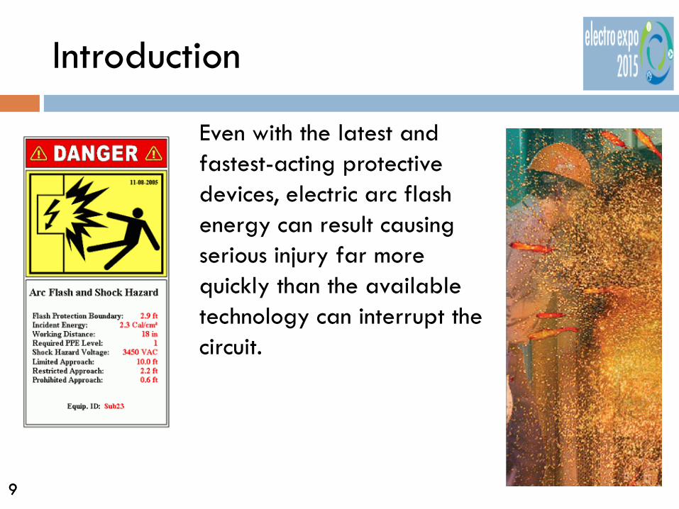
Even with the latest and fastest-acting protective devices, electric arc flash energy can result causing serious injury far more quickly than the available technology can interrupt the circuit.

10 10
Introduction
The most effective form of electrical shock protection is to avoid shock altogether. This is best accomplished through proper system design, operation, and effective maintenance following all safety procedures.
11 11
Introduction
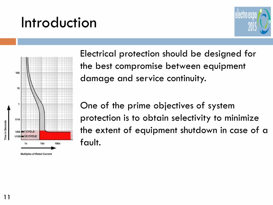
Electrical protection should be designed for the best compromise between equipment damage and service continuity. One of the prime objectives of system protection is to obtain selectivity to minimize the extent of equipment shutdown in case of a fault.

12 12
Introduction
Coordination (Selective). Localization of an overcurrent condition to restrict outages to the circuit or equipment affected, accomplished by the selection and installation of overcurrent protective devices and their ratings or settings for the full range of available overcurrents, from overload to the maximum available fault current, and for the full range of overcurrent protective device opening times associated with those overcurrents.

13 13
Introduction
Engineers, designers and contractors are responsible to provide selective coordination per the National Electrical Code in all buildings where a non-orderly shutdown would introduce additional hazards or risk, in healthcare facilities, emergency systems and other specific Articles in the National Electrical Code.
14 14
Introduction
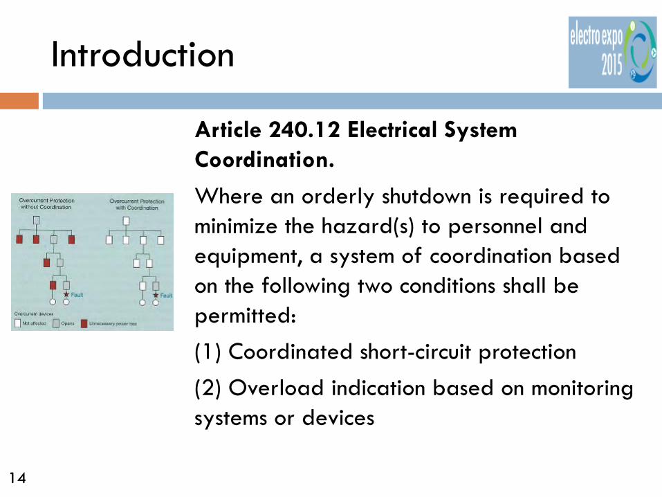
Article 240.12 Electrical System Coordination.
Where an orderly shutdown is required to minimize the hazard(s) to personnel and equipment, a system of coordination based on the following two conditions shall be permitted: (1) Coordinated short-circuit protection (2) Overload indication based on monitoring systems or devices

15 15
Introduction
Article 240.12 Electrical System Coordination.
Prior to the 1984 National Electrical Code this article only applied to “Industrial facilities”. The 1984 National Electrical Code was changed to required selective coordination where a orderly shutdown is required to minimize hazards in ALL facilities. This language remains the same in the 2014 code.
16 16
Introduction
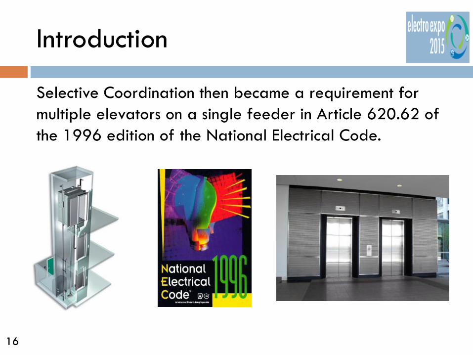
Selective Coordination then became a requirement for multiple elevators on a single feeder in Article 620.62 of the 1996 edition of the National Electrical Code.

17 17
Introduction
620.62 Selective Coordination. Where more than one driving machine disconnecting means is supplied by a single feeder, the overcurrent protective devices in each disconnecting means shall be selectively coordinated with any other supply side overcurrent protective devices. Selective coordination shall be selected by a licensed professional engineer or other qualified person engaged primarily in the design, installation, or maintenance of electrical systems. The selection shall be documented and made available to those authorized to design, install, inspect, maintain, and operate the system.
2014 NEC

18 18
Introduction
In the 2005 NEC, selective coordination was expanded to include:
Emergency Systems in Section 700.27 Legally Required Standby Systems in Section 701.18

19 19
Introduction
700.28 Selective Coordination.
Emergency system(s) overcurrent devices shall be selectively coordinated with all supply-side overcurrent protective devices. Selective coordination shall be selected by a licensed professional engineer or other qualified persons engaged primarily in the design, installation, or maintenance of electrical systems. The selection shall be documented and made available to those authorized to design, install, inspect, maintain, and operate the system.
2014 NEC
20 20
Introduction
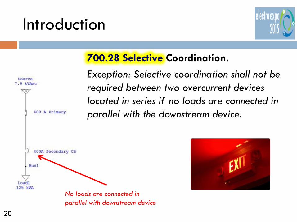
700.28 Selective Coordination.
Exception: Selective coordination shall not be required between two overcurrent devices located in series if no loads are connected in parallel with the downstream device.
No loads are connected in parallel with downstream device

21 21
Introduction
701.27 Selective Coordination. Legally required standby system(s) overcurrent devices shall be selectively coordinated with all supply-side overcurrent protective devices. Selective coordination shall be selected by a licensed professional engineer or other qualified persons engaged primarily in the design, installation, or maintenance of electrical systems. The selection shall be documented and made available to those authorized to design, install, inspect, maintain, and operate the system.
2014 NEC
22 22
Introduction
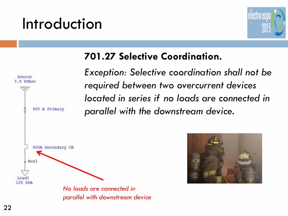
701.27 Selective Coordination.
Exception: Selective coordination shall not be required between two overcurrent devices located in series if no loads are connected in parallel with the downstream device.
No loads are connected in parallel with downstream device

23 23
Introduction
In the 2008 NEC, selective coordination requirements were expanded into Article 708 for Critical Operations Power Systems (COPS) in Section 708.54…..

24 24
Introduction
708.54 Selective Coordination. Critical operations power system(s) overcurrent devices shall be selectively coordinated with all supply-side overcurrent protective devices. Selective coordination shall be selected by a licensed professional engineer or other qualified persons engaged primarily in the design, installation, or maintenance of electrical systems. The selection shall be documented and made available to those authorized to design, install, inspect, maintain, and operate the system.
2014 NEC

25 25
Introduction
708.54 Selective Coordination.
Exception: Selective coordination shall not be required between two overcurrent devices located in series if no loads are connected in parallel with the downstream device.

26 26
Introduction
708.52(D) Selectivity. Ground-fault protection for operation of the service and feeder disconnecting means shall be fully selective such that the feeder device, but not the service device, shall open on ground faults on the load side of the feeder device. Separation of ground-fault protection time-current characteristics shall conform to the manufacturer’s recommendations and shall consider all required tolerances and disconnect operating time to achieve 100 percent selectivity.
Informational Note: See 230.95, Informational Note No. 4, for transfer of alternate source where ground-fault protection is applied.
2014 NEC
27 27
Introduction
Health Care Facilities
Although Ground Fault Selectivity was required in the National Electrical Code prior to 1984, Overcurrent Device Selective Coordination was added as a requirement for the entire essential electrical distribution system of Health Care Facilities in the 2014 NEC.
2014 NEC

28 28
Introduction
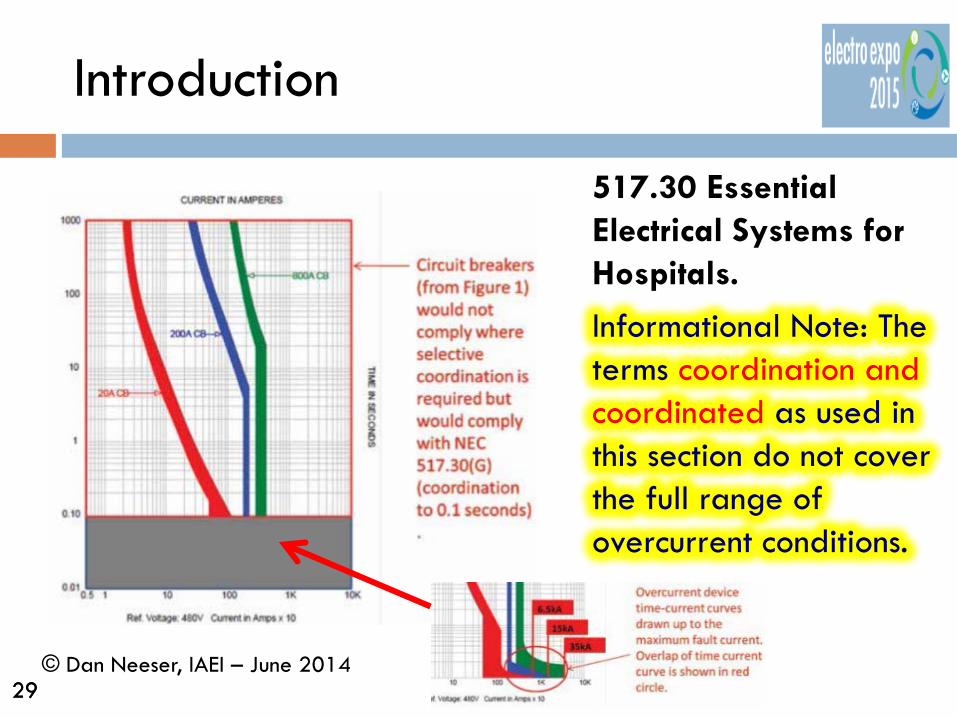
517.30 Essential Electrical Systems for Hospitals.
(G) Coordination. Overcurrent protective devices serving the essential electrical system shall be coordinated for the period of time that a fault’s duration extends beyond 0.1 second.
Essential System consists of the Equipment, Life Safety and Critical Branches
2014 NEC
29 29
Introduction
517.30 Essential Electrical Systems for Hospitals.
Informational Note: The terms coordination and coordinated as used in this section do not cover the full range of overcurrent conditions.
© Dan Neeser, IAEI – June 2014
30 30
Introduction
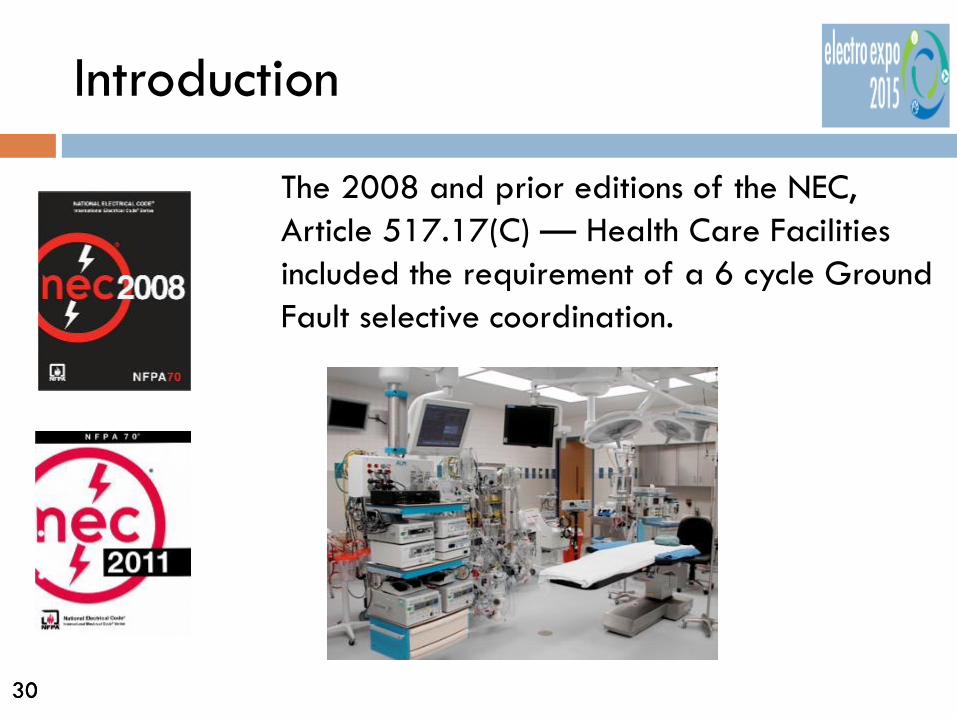
The 2008 and prior editions of the NEC, Article 517.17(C) — Health Care Facilities included the requirement of a 6 cycle Ground Fault selective coordination.

31 31
Introduction
517.17 Ground-Fault Protection. (C) Selectivity. Ground-fault protection for operation of the service and feeder disconnecting means shall be fully selective such that the feeder device, but not the service device, shall open on ground faults on the load side of the feeder device. Separation of ground-fault protection time-current characteristics shall conform to manufacturer’s recommendations and shall consider all required tolerances and disconnect operating time to achieve 100 percent selectivity.
Since the 2011 Code GFP is now required to have 100% selectivity.

32 32
Fuses, Circuit Breakers and Relays
Fuses are one time only devices and are available in different types:
Fast Acting Time Delay Slow Very Slow Current Limiting

33 33
Fuses, Circuit Breakers and Relays
Because of the differences in the way each fuse reacts to clear a fault, fuse dimensions have been standardized in an attempt to prevent accidental fuse replacement with less effective protection.
34 34
Fuses, Circuit Breakers and Relays
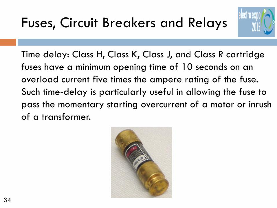
Time delay: Class H, Class K, Class J, and Class R cartridge fuses have a minimum opening time of 10 seconds on an overload current five times the ampere rating of the fuse. Such time-delay is particularly useful in allowing the fuse to pass the momentary starting overcurrent of a motor or inrush of a transformer.

35 35
Fuses, Circuit Breakers and Relays
How do manufacturers get fuses to time delay?
They use dual elements!

36 36
Fuses, Circuit Breakers and Relays
Dual-element fuse: A cartridge fuse having two or more current-responsive elements of different fusing characteristics in series in a single cartridge. Labeling a fuse as dual-element means this fuse meets Underwriters Laboratories (UL) time-delay requirements.

37 37
Fuses, Circuit Breakers and Relays
A time delay fuse can carry five times rated current for a minimum of 10 seconds for Class J, Class H, Class K, and Class R. Smaller 250 V, 30 amp case size Class H, Class K, and Class R fuses have a minimum opening time reduced to 8 seconds for five times the rated current.

38 38
Fuses, Circuit Breakers and Relays
Keep in mind that delay is applied to the opening time of a fuse when in excess of 1 cycle. The actual clearing time may vary considerably between types and manufacturers but may still be within established standards.

39 39
Fuses, Circuit Breakers and Relays
For most low-voltage circuit breakers, the sensing elements are an integral part of the circuit breaker. These trip units may be thermal and/or magnetic series devices. The trip units may also be separate electronic devices used with CTs mounted in the circuit breaker.
40 40
Fuses, Circuit Breakers and Relays
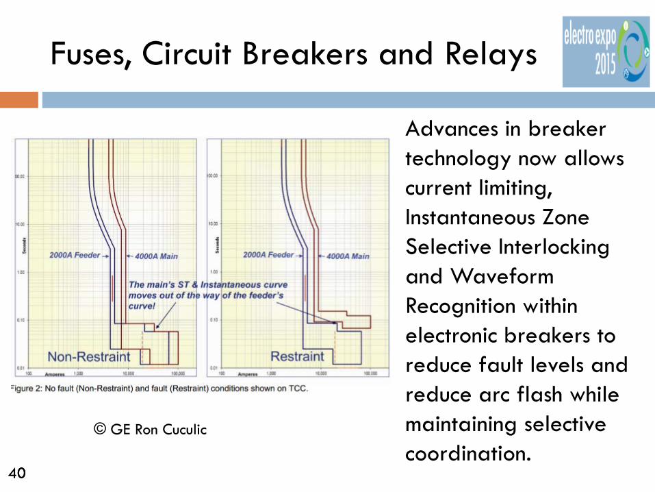
Advances in breaker technology now allows current limiting, Instantaneous Zone Selective Interlocking and Waveform Recognition within electronic breakers to reduce fault levels and reduce arc flash while maintaining selective coordination.
© GE Ron Cuculic

41 41
Fuses, Circuit Breakers and Relays
The advantage of waveform recognition is a peak-to-peak and peak sensing trip unit which can extend down to low voltage devices.
© GE Ron Cuculic

42 42
Reading a Time Current Curve
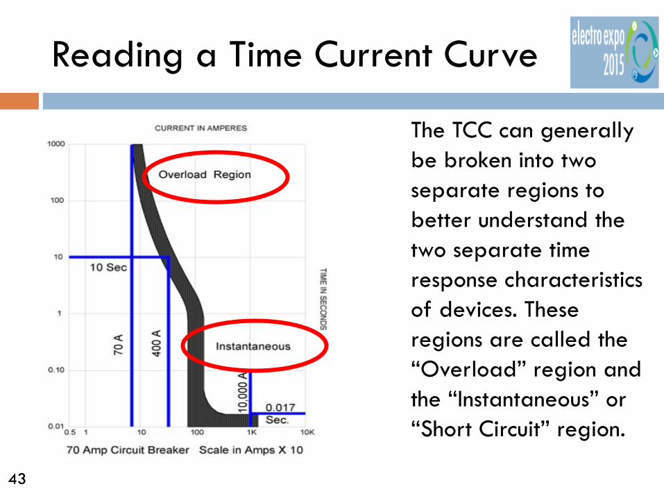
A typical coordination shows the response of Overcurrent Protective Devices to fault currents on Time-Current Curves (TCCs) plotted on Log-Log graph paper. The horizontal axis represents current in amperes. The vertical axis represents time in seconds.
TIME
CURRENT
43 43
Reading a Time Current Curve
The TCC can generally be broken into two separate regions to better understand the two separate time response characteristics of devices. These regions are called the “Overload” region and the “Instantaneous” or “Short Circuit” region.
44 44
Reading a Time Current Curve
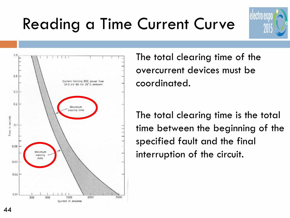
The total clearing time of the overcurrent devices must be coordinated. The total clearing time is the total time between the beginning of the specified fault and the final interruption of the circuit.
45 45
Reading a Time Current Curve
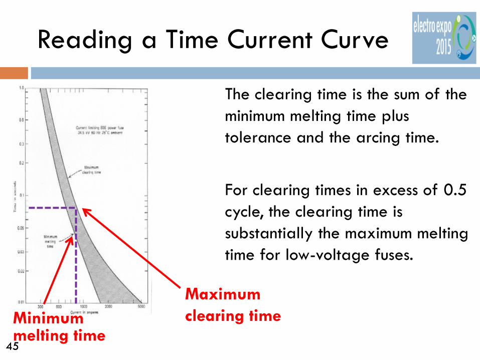
The clearing time is the sum of the minimum melting time plus tolerance and the arcing time. For clearing times in excess of 0.5 cycle, the clearing time is substantially the maximum melting time for low-voltage fuses.
Minimum melting time
Maximum clearing time

46 46
Reading a Time Current Curve
TCC’s are used by designers as graphical representations to show coordinated overcurrent protection devices. Devices are plotted on the TCC to indicate how long it will take a device to react under a certain fault current level.
FAULT CURRENT
TIME

47 47
Reading a Time Current Curve
For selectivity, the total clearing I2t of the downstream fuse should be less than the minimum melting I2t of the upstream fuse.
38.5 second clearing time between 100 and 200 amp fuses at 700 Amps short circuit.

48 48
Reading a Time Current Curve
In low-voltage fuse applications, coordination may sometimes be determined through the use of selectivity ratio tables Note: Fuse
ratio tables cannot be used with fuses at different voltages or from different manufacturers

49 49
Reading a Time Current Curve
Arc Flash Energy is measured within the trip curve represented between the min and max clearing time.
Bolted Fault – very large current but very small time reduces arc fault energy
Overload Region – smaller current but longer time increases arc fault energy
© IAEI Thomas A. Domitrovich

50 50
Circuit Breaker Trip Response Functions
The “Total Clearing time” for an OCPD has two main components - the “operating time” and an “arcing time.”
51 51
Circuit Breaker Trip Response Functions
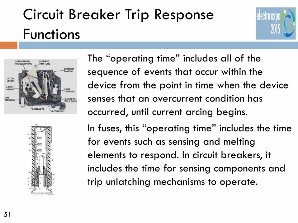
The “operating time” includes all of the sequence of events that occur within the device from the point in time when the device senses that an overcurrent condition has occurred, until current arcing begins. In fuses, this “operating time” includes the time for events such as sensing and melting elements to respond. In circuit breakers, it includes the time for sensing components and trip unlatching mechanisms to operate.

52 52
Circuit Breaker Trip Response Functions
The “arcing time” is the time taken for the arc to be extinguished and the current is reduced to zero.

53 53
Circuit Breaker Trip Response Functions
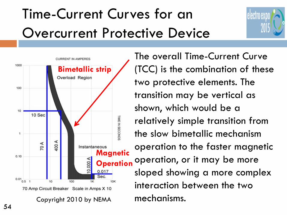
A simple thermal magnetic circuit breaker consists of two key tripping mechanisms. The curved inverse time portion known as the “Overload” region is generally controlled by a bimetallic strip that flexes with heat caused by current flowing through the strip or by heat caused by a nearby resistive element that has current flowing through it.
54 54
Time-Current Curves for an Overcurrent Protective Device
The overall Time-Current Curve (TCC) is the combination of these two protective elements. The transition may be vertical as shown, which would be a relatively simple transition from the slow bimetallic mechanism operation to the faster magnetic operation, or it may be more sloped showing a more complex interaction between the two mechanisms.
Bimetallic strip
Magnetic Operation
Copyright 2010 by NEMA
55 55
Time-Current Curves for an Overcurrent Protective Device
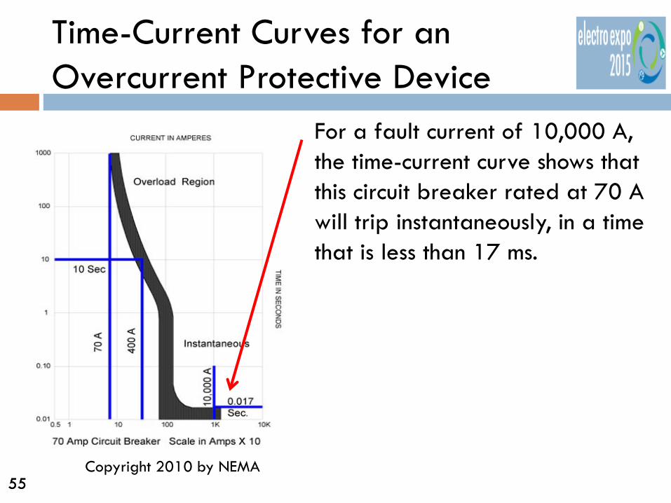
For a fault current of 10,000 A, the time-current curve shows that this circuit breaker rated at 70 A will trip instantaneously, in a time that is less than 17 ms.
Copyright 2010 by NEMA

56 56
Time-Current Curves for an Overcurrent Protective Device
For a fault current of 400 amps, the breaker will clear in the overload region of the trip curve at approximately 10 seconds.
Copyright 2010 by NEMA

57 57
Design requirements
The designer of an electrical power system should determine: The sizes and types of loads.
The available short-circuit current at the point of
delivery.
The time-current curves and settings of the utility protective devices.
Ratings and settings of overcurrent protective devices proposed for the user’s system.

58 58
Design requirements
The designer can then proceed with a preliminary system design and preparation of a one-line diagram.

59 59
Design requirements
There are various methods to obtain Selective Coordination between OCPDs. Generally, selectivity is achieved by adjusting the line side or source device to be less sensitive and slower than the load side device. This is particularly true in the overload region of the various trip curves.

60 60
Design requirements
The NEC has exceptions where two or more devices in series need not be selective. The intent is that when two or more devices are feeding the exact same circuit with no loads connected in between, then they need not be selective with each other. However, they do need to be selective with other devices above and below.

61 61
Design requirements
Exceptions include: Two protective devices of the same continuous ampere rating directly connected in series. The feeder breaker on the primary side of a transformer and the main breaker on the secondary side of a transformer.

62 62
Design requirements
For both of these exceptions, it would not matter which OCPD would open, or if they both opened, since the protected circuit would be disconnected in either case.
63 63
Design requirements
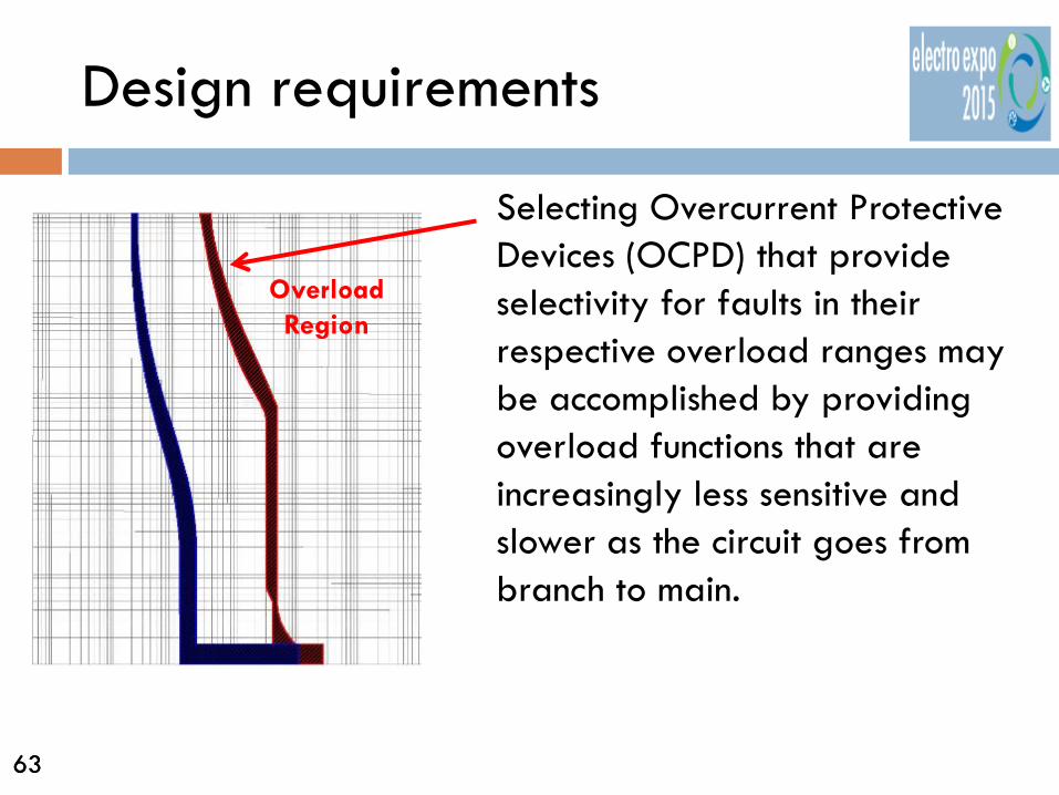
Selecting Overcurrent Protective Devices (OCPD) that provide selectivity for faults in their respective overload ranges may be accomplished by providing overload functions that are increasingly less sensitive and slower as the circuit goes from branch to main.
Overload Region

64 64
Design requirements
For any specific fault current, if the load side device operates in its instantaneous region and the line side device operates in its overload region, selectivity is easily achieved. However, when a fault is in the range where the instantaneous responses of multiple series devices overlap then selectivity may be harder to achieve.
Fault current level
Down Stream Device trips first
Harder to Achieve Here

65 65
Design requirements
The end of the instantaneous trip represents the device’s short circuit rating.

66 66
Fixed Thermal-Magnetic Type Circuit Breaker
UL 489 specifies the maximum tolerance (-20% to +30%) allowed for an adjustable instantaneous setting marked on the circuit breaker. Manufacturer’s TCCs may demonstrate less tolerance for a particular device based on the device’s actual performance.
67 67
Fixed Thermal-Magnetic Type Circuit Breaker
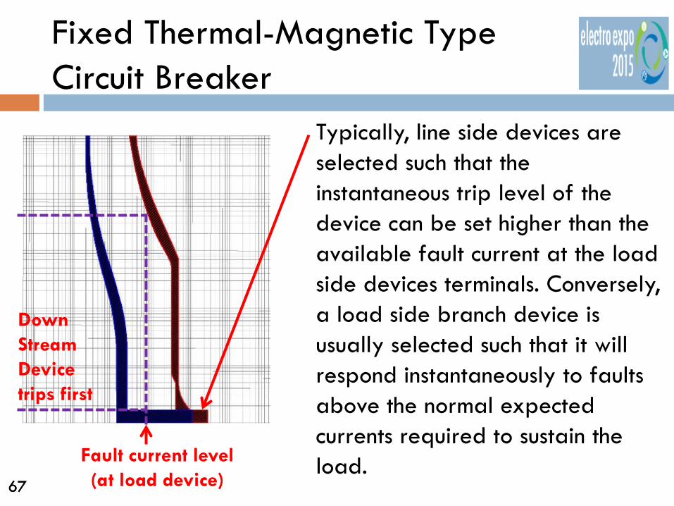
Typically, line side devices are selected such that the instantaneous trip level of the device can be set higher than the available fault current at the load side devices terminals. Conversely, a load side branch device is usually selected such that it will respond instantaneously to faults above the normal expected currents required to sustain the load.
Fault current level (at load device)
Down Stream Device trips first
68 68
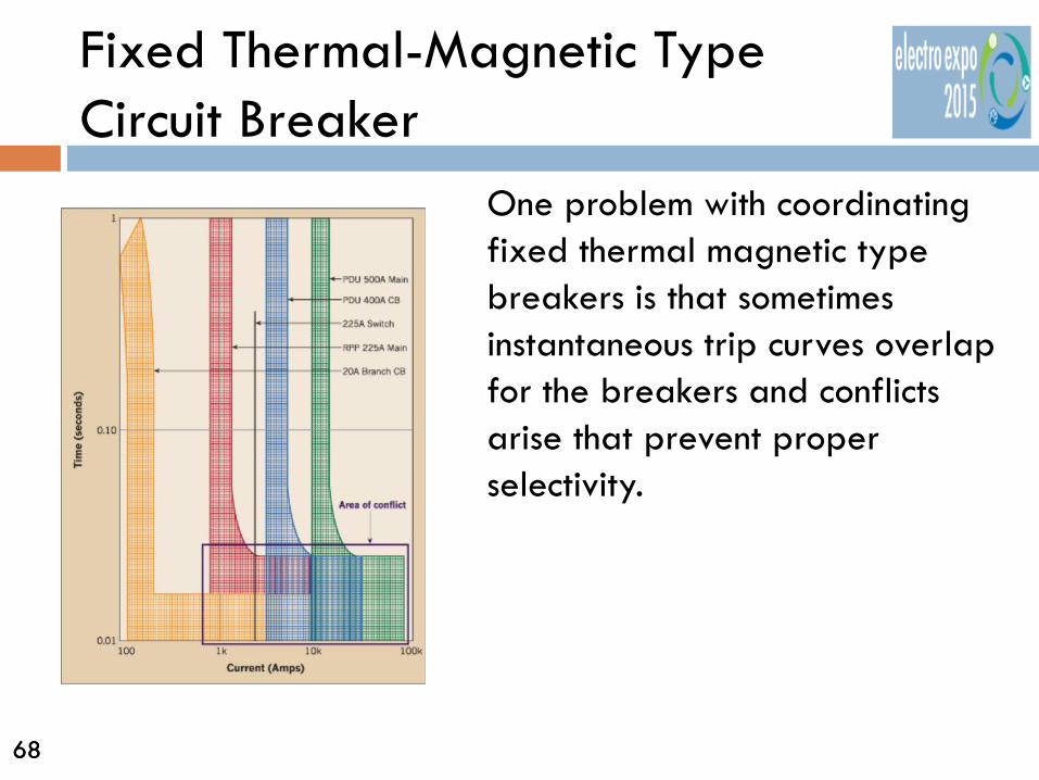
Fixed Thermal-Magnetic Type Circuit Breaker
One problem with coordinating fixed thermal magnetic type breakers is that sometimes instantaneous trip curves overlap for the breakers and conflicts arise that prevent proper selectivity.

69 69
Adjustable Trip Circuit Breakers
Adjustable Instantaneous trip breakers with delay settings are available from most manufacturers over a wide range of circuit breaker sizes and types.

70 70
Adjustable Trip Circuit Breakers
An adjustable instantaneous trip breaker offer system designers greater flexibility by allowing selection of an optimized instantaneous protection function that allows normal load fluctuations while tripping for higher abnormal currents.
Long Delay Pickup
Long Delay Time
Short Delay Pickup
Short Delay
Instantaneous Ground Fault
Ground Fault Delay
I2T In
I2T Out
71 71
Adjustable Trip Circuit Breakers
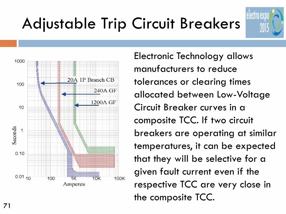
Electronic Technology allows manufacturers to reduce tolerances or clearing times allocated between Low-Voltage Circuit Breaker curves in a composite TCC. If two circuit breakers are operating at similar temperatures, it can be expected that they will be selective for a given fault current even if the respective TCC are very close in the composite TCC.

72 72
Adjustable Trip Circuit Breakers
Electronic trip units are characterized by their adjustability, their accuracy, and their repeatability. This allows less variability in the point at which the device will pickup during a fault condition. As a result, circuit breakers with electronic trip units typically have much narrower tolerance bands as compared to other designs of Overcurrent Protective Devices (OCPD).
73 73
Adjustable Trip Circuit Breakers
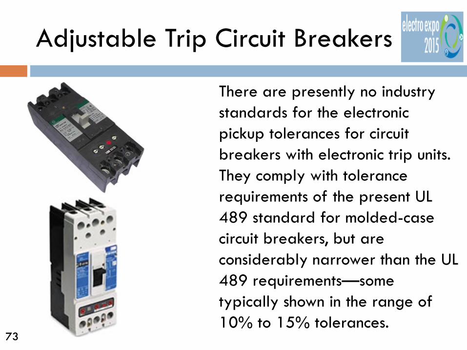
There are presently no industry standards for the electronic pickup tolerances for circuit breakers with electronic trip units. They comply with tolerance requirements of the present UL 489 standard for molded-case circuit breakers, but are considerably narrower than the UL 489 requirements—some typically shown in the range of 10% to 15% tolerances.

74 74
Adjustable Trip Circuit Breakers
Electronic circuit breaker designs provide the electrical system designer with two key advantages: • They provide maximum
flexibility in adjusting the desired level of pickup current.
• They inherently have the narrowest tolerances for coordinating the response of multiple OCPDs.

75 75
Adjustable Trip Circuit Breakers
Molded Case
Adjustable with Inst. Trip
Adjustable w/out Inst. Trip
76 76
Adjustable Trip Circuit Breakers
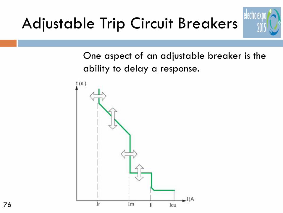
One aspect of an adjustable breaker is the ability to delay a response.
77 77
Adjustable Trip Circuit Breakers
Whenever breaker responses are delayed, it is very important to have the "withstand current" rating is as high as possible. Short Time Withstand ratings allow the circuit breaker to intentionally delay up to 30 cycles (0.5 seconds) before tripping. The result is to enable the upstream breaker to remain closed, allowing selective coordination with downstream circuit breakers to open and clear a fault.

78 78
Adjustable Trip Circuit Breakers
The typical range of instantaneous pickup adjustment for circuit breakers is from around 1.5x up to 12x (or higher) times the continuous ampere rating of the circuit breaker, depending on the manufacturer and design. A 100 A circuit breaker could be adjusted to trip instantaneously at the 1.5x setting (150 A), or as high as the 12x setting (1200 A).

79 79
Adjustable Trip Circuit Breakers
Some circuit breakers have electronic designs that allow the instantaneous function to be turned OFF. When a circuit breaker with an electronic trip unit is specified without an instantaneous pickup function, it typically contains what’s called an “instantaneous override function”.

80 80
Instantaneous Override Function
Instantaneous Override “The override trip is an independent instantaneous trip set near the circuit-breaker withstand level that overrides the electronic logic trip unit to cause the circuit breaker to open without delay at very large fault levels. (IEEE 1015-2006 “Blue Book”)

81 81
Instantaneous Override Function
The instantaneous override function is also set to pickup and trip the circuit breaker instantaneously, but its pickup level is permanently set at a much higher level than the typical maximum instantaneous settings of 12 times the continuous ampere rating of the circuit breaker. A 70 amp circuit with 12x inst. Pickup (840 amps) may be as high the Short Time Withstand capability of the circuit breaker, of say 10,000 A.
82 82
Instantaneous Override Function
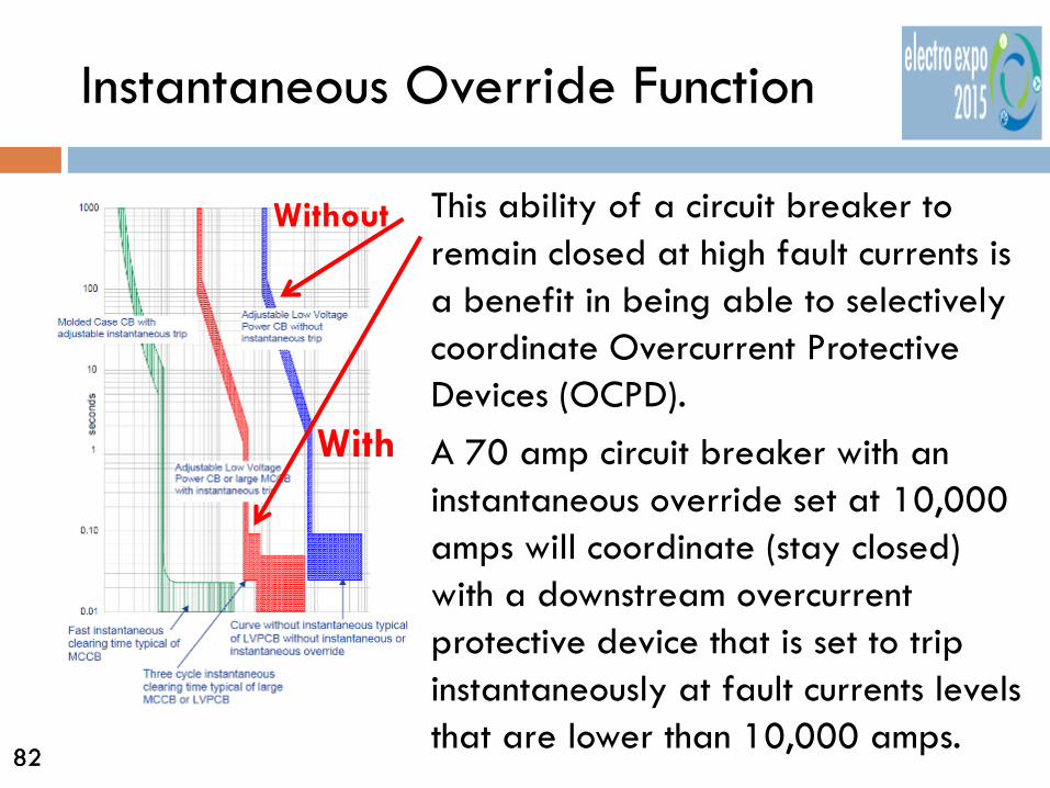
This ability of a circuit breaker to remain closed at high fault currents is a benefit in being able to selectively coordinate Overcurrent Protective Devices (OCPD). A 70 amp circuit breaker with an instantaneous override set at 10,000 amps will coordinate (stay closed) with a downstream overcurrent protective device that is set to trip instantaneously at fault currents levels that are lower than 10,000 amps.
With
Without

83 83
Coordination Study
The traditional method for determining selective coordination and the protection of equipment is via an electronic coordination study. This method provides a thorough analysis of the requirements, and results in documented evidence that the coordination and protection requirements have been adequately achieved.

84 84
Coordination Study
The selective coordination study involves a time-current coordination study by comparing the timing characteristics of the various protective devices being considered with each other. In addition, the study also looks at the potential damage characteristics of equipment being protected.
85 85
Coordination Study
The short circuit currents available at different points in the system must also be understood. To ensure an optimal analysis, a coordination study is typically performed in conjunction with a Short Circuit Study. This study evaluates the short circuit currents that are available in the system and allow the designer to see, at the same time, the impact of these short circuit currents on the selection of devices to meet both selective coordination and protection requirements.

86 86
Coordination Study
The time-current trip curves provide a traditional and quick way to identify if selective coordination exists between Overcurrent Protective Devices (OCPD), however, sometimes there is more to the story.

87 87
Instantaneous or Short Circuit Region
Traditional interpretation of time-current curves in the instantaneous region is the same as the interpretation in the overload region. An overlap of the curves indicates potential lack of selectivity and, a lack of overlap indicates probable selectivity.

88 88
Instantaneous or Short Circuit Region The line side circuit breaker will react to the peak let-through current allowed to flow by the smaller, or faster, OCPD for a given prospective fault current.
89 89
Peak Let-Through Currents of Circuit Breaker
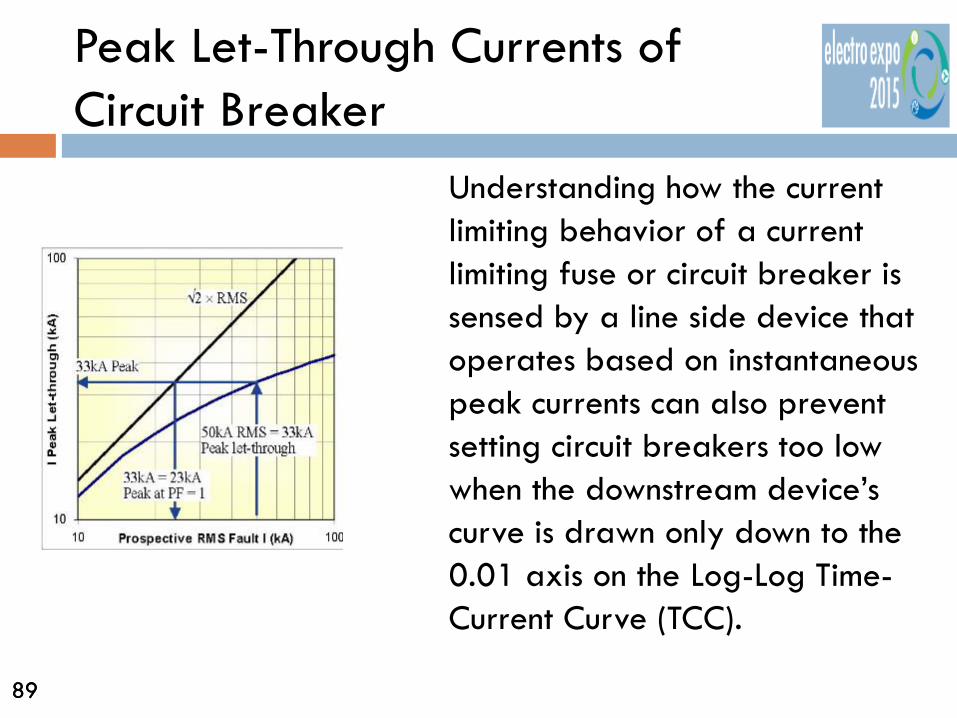
Understanding how the current limiting behavior of a current limiting fuse or circuit breaker is sensed by a line side device that operates based on instantaneous peak currents can also prevent setting circuit breakers too low when the downstream device’s curve is drawn only down to the 0.01 axis on the Log-Log Time-Current Curve (TCC).

90 90
Breakers Combinations
Manufacturers have developed tables of combinations of current limiting circuit breakers in series and also electronic trips. Testing performed by the manufacturers under a variety of fault conditions confirm the combinations.

91 91
Fuse Combinations
Fuse manufacturers have also developed tables selective coordination for current limiting fuses. The tables are based on ratios of upstream vs. downstream fuse size.
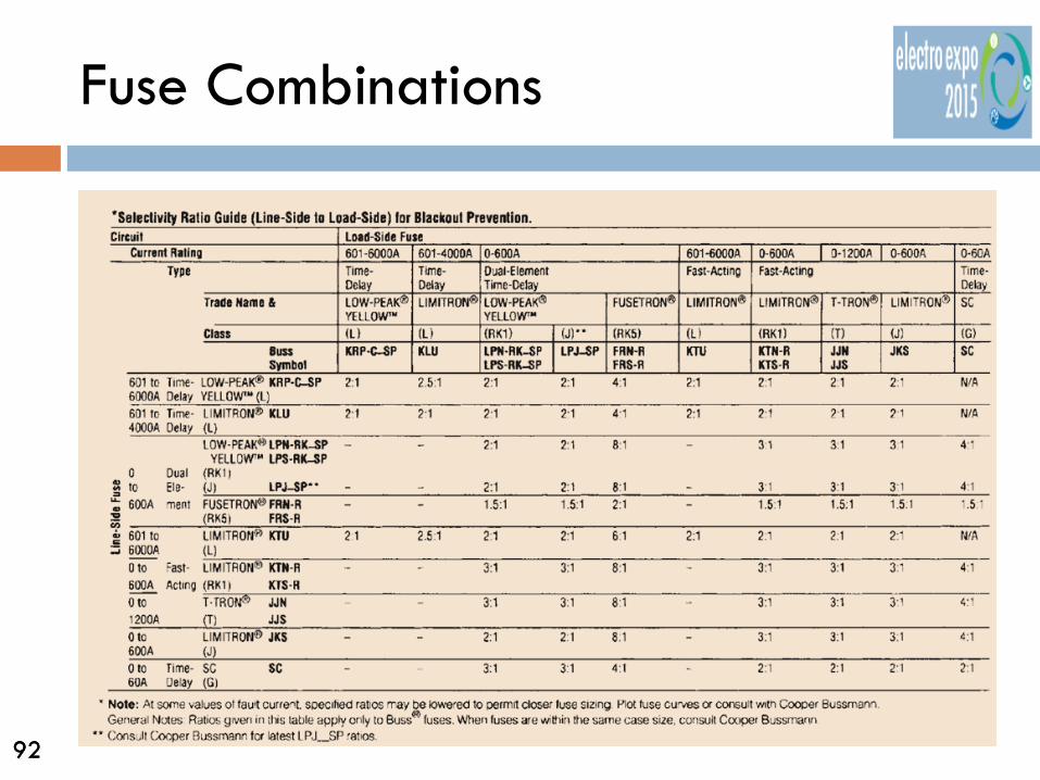
92 92
Fuse Combinations

93 93
Coordinating Ground-Fault Protection of Equipment
Article 230.95. Requires equipment ground-fault protection to be provided on solidly grounded wye electric services of more than 150 volts to ground but not exceeding 600 volts phase-to-phase for each service disconnect rated 1000A or more. Exceptions for legally required emergency systems as well as systems where a disorderly shutdown may present more risk to human life than a fire caused by an arcing ground fault.

94 94
Coordinating Ground-Fault Protection of Equipment
Article 700.6(D). Permits indication only of a ground fault condition on the alternate power source for emergency systems.
95 95
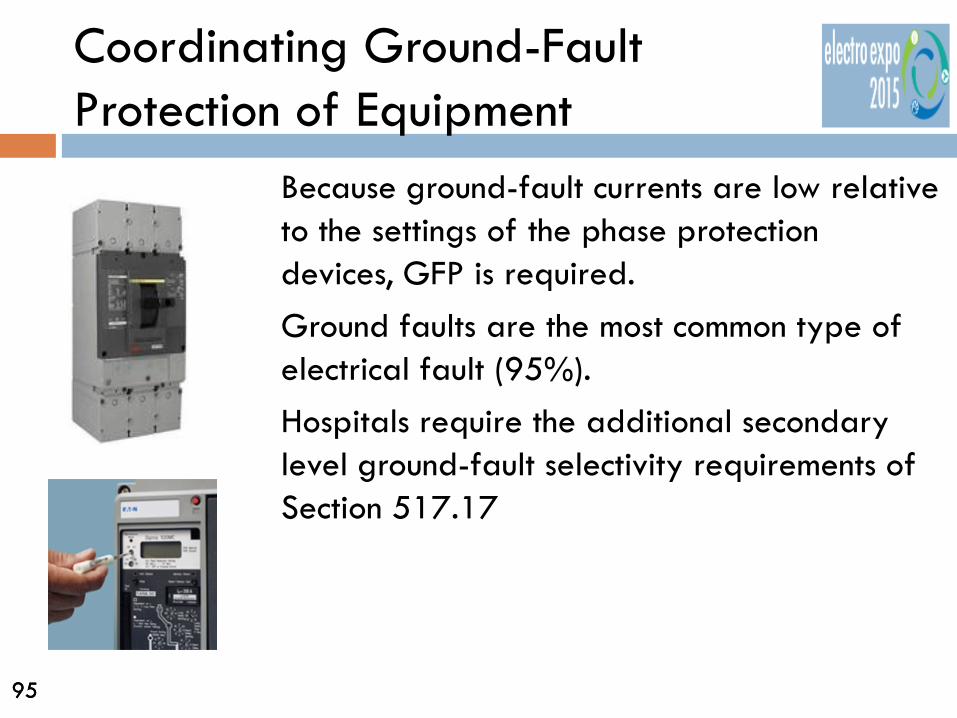
Coordinating Ground-Fault Protection of Equipment
Because ground-fault currents are low relative to the settings of the phase protection devices, GFP is required. Ground faults are the most common type of electrical fault (95%). Hospitals require the additional secondary level ground-fault selectivity requirements of Section 517.17

96 96
Coordinating Ground-Fault Protection of Equipment
UL 1053 defines maximum clearing time at 150% of nominal pickup setting and at 2 seconds. The NEC defines the maximum GFP pickup to be 1200 A and the maximum clearing time at 3000 A at 1 second.

97 97
Coordinating Ground-Fault Protection of Equipment
Because of standard requirements, the shape of the ground-fault function’s protective curve is more limited than the shape of phase protection devices.

98 98
Coordinating Ground-Fault Protection of Equipment
Phase protection devices cannot separate a ground fault from a phase fault. A ground fault with enough fault current can operate phase protection. A phase fault should never operate properly functioning ground-fault protection
Not Selective

99 99
Coordinating Ground-Fault Protection of Equipment
Because a substantial ground fault could trip a GFP device, complete system selectivity requires phase protection devices and ground-fault protection devices be coordinated with each other.
Barely Selective
100 100
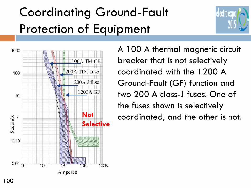
Coordinating Ground-Fault Protection of Equipment
A 100 A thermal magnetic circuit breaker that is not selectively coordinated with the 1200 A Ground-Fault (GF) function and two 200 A class-J fuses. One of the fuses shown is selectively coordinated, and the other is not. Not
Selective

101 101
Coordinating Ground-Fault Protection of Equipment
In all cases the downstream OCP device will need to be significantly smaller than the device that incorporates the ground-fault protection. This is a problem with secondary level GFP devices that are smaller and coordinating them with branch circuit breakers such as in hospitals.
Barely Selective
102 102
Design Guidelines
The earlier in the design process that the various selective coordination requirements are considered, the smoother the entire process will be. Getting preliminary data about the available fault currents from the utility and/or generators, estimates of cable lengths, and OCPDs typically results in designs that minimize re-work and revisions.

103 103
Determine the available fault currents
In schemes involving both a normal utility power source and an alternate emergency generator power source, the design engineer must include both the utility and the generator power source, in the analysis of the available fault currents.

104 104
Determine the available fault currents
In general, generators will typically have much lower available fault current than the normal utility source. There are, however, parallel generator applications such as in large data centers and hospitals where the available fault currents from the generator power source may be quite high.

105 105
Start at the smallest device and work from the bottom up
To begin a selective coordination analysis, start with the smallest device that is the farthest downstream from the point of the utility system. Using the fault current available to this device from the Short Circuit study, examine if this downstream device will coordinate with the device that is immediately upstream from it.
Copyright 2010 by NEMA

106 106
Start at the smallest device and work from the bottom up
This examination may be done looking at both Time-Current Curves and/or via Short Circuit Selective Coordination Tables, provided by the manufacturers of the devices.
Copyright 2010 by NEMA

107 107
Start at the smallest device and work from the bottom up
On the fault current axis, locate the value of the available fault current at the downstream device. At this fault current value, determine if the upstream device can be set to remain closed, either via adjustable pickup or time-delay settings, while allowing the downstream device to open. If these two devices are selectively coordinated, there will typically not be any overlap in their time-current curve plots.
Short Circuit Current
108 108
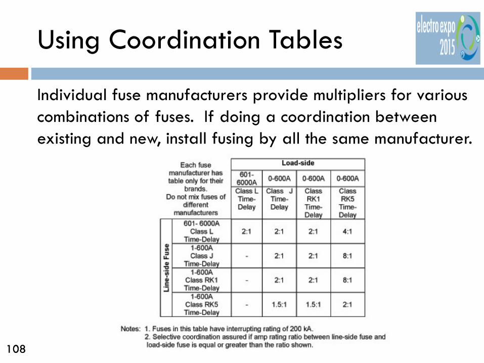
Using Coordination Tables
Individual fuse manufacturers provide multipliers for various combinations of fuses. If doing a coordination between existing and new, install fusing by all the same manufacturer.

109 109
Using Coordination Tables
Manufacturers of circuit breakers also have instantaneous trip selectivity tables.
GE Spectra RMS Adjustable Trip Molded Case CB
Molded case circuit breaker

110 110
Using Coordination Tables
Even though these two breakers look like they don’t coordinate in the instantaneous region, they have been tested together and are selective at 9,772 Amps short circuit. Any higher short circuit and they don’t!
9,772 Amps

111 111
Mixing of Overcurrent Protective Devices
When fuses are on the line side of circuit breakers, the let-through energy of a circuit breaker may or may not be enough to melt an upstream fuse. Neither manufacturers of circuit breakers nor fuses commonly test or provide sufficient information to allow the required instantaneous trip analysis to be performed by system design professionals.

112 112
Mixing of Overcurrent Protective Devices
When selectivity of fuses on the line side above circuit breaker combinations must be analyzed beyond where the fuse crosses the 0.1 second axis of the time-current curve, the circuit breaker manufacturer should be consulted.
113 113
Mixing of Overcurrent Protective Devices
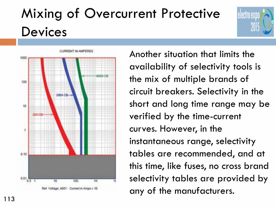
Another situation that limits the availability of selectivity tools is the mix of multiple brands of circuit breakers. Selectivity in the short and long time range may be verified by the time-current curves. However, in the instantaneous range, selectivity tables are recommended, and at this time, like fuses, no cross brand selectivity tables are provided by any of the manufacturers.

114 114
Selective Coordination Tips
Where possible, split up larger loads into smaller loads such that the resulting fault currents will be lower. The lower fault currents may result in smaller protective devices and conducting cables, etc., thereby making selective coordination simpler. This may take more space and possibly higher total costs for the smaller load devices, but will allow better system design.
MDP – 800A
PP1 200A
PP2 200A
MDP – 800A
PP1 400A
VS.
√

115 115
Selective Coordination Tips
The fewer the number of levels of OCPDs, the simpler selective coordination becomes.
Three levels of Coordination
Two levels of Coordination
Copyright 2010 by NEMA
116 116
Selective Coordination Tips
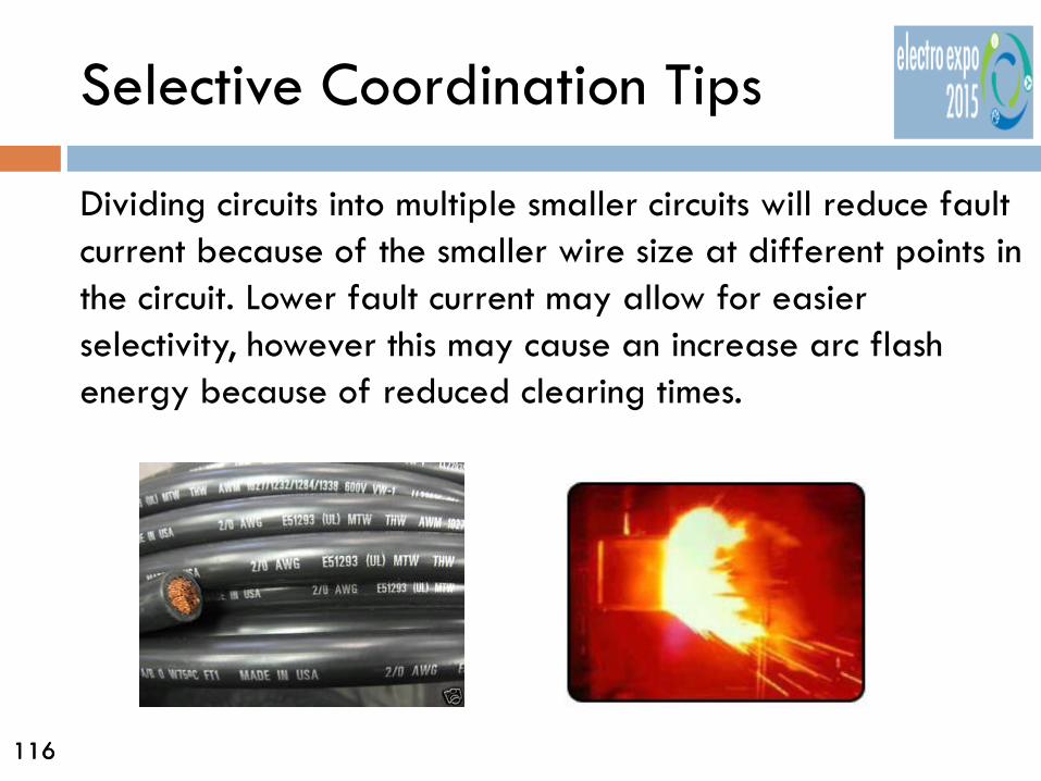
Dividing circuits into multiple smaller circuits will reduce fault current because of the smaller wire size at different points in the circuit. Lower fault current may allow for easier selectivity, however this may cause an increase arc flash energy because of reduced clearing times.

117 117
Arc Flash Energy
Selective Coordination requires upstream Overcurrent Protective Devices (OCPD) to wait longer to enable downstream protective devices to clear the fault. A conflicting situation is put in place: Selective Coordination involves having OCPDs to remain closed during fault conditions, while Arc Flash Energy reduction requires these same devices to open as quickly as possible.

118 118
Arc Flash Energy
While the level of arc energy that results in a selectively coordinated system may be fully within acceptable levels for equipment protection from damage, this level of arc energy is often very dangerous to personnel that may be working near that electrical equipment.

119 119
Arc Flash Energy
The NFPA 70E Standard for Electrical Safety in the Workplace recognizes that there are circumstances that allow working on live, energized electrical equipment:
1. Non-orderly shutdown will cause additional or increased hazard.
2. Hospitals or patient care areas that serve life support equipment in critical care areas.
3. Less than 50 volts
120 120
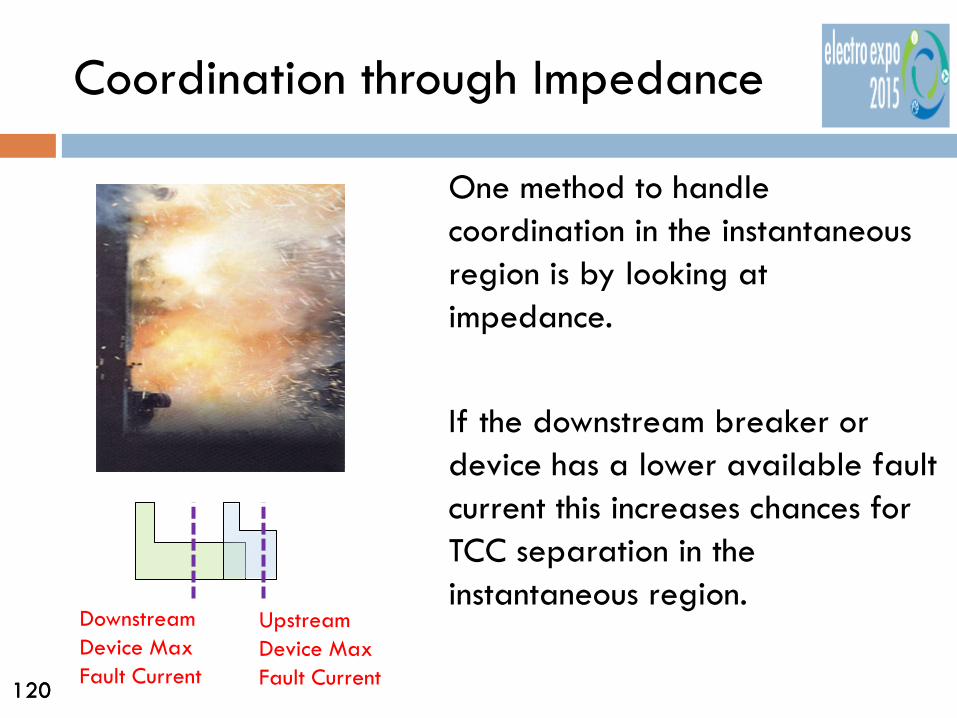
Coordination through Impedance
One method to handle coordination in the instantaneous region is by looking at impedance. If the downstream breaker or device has a lower available fault current this increases chances for TCC separation in the instantaneous region.
Downstream Device Max Fault Current
Upstream Device Max Fault Current

121 121
Waveform Recognition
Another technique to handle Instantaneous Coordination is through Waveform Recognition. For this technique to work, the upstream breaker must have the WFR capable trip unit and the downstream device is a current limiting (CL) circuit breaker or fuse
122 122
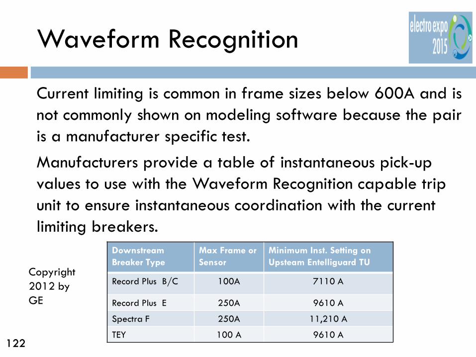
Waveform Recognition
Current limiting is common in frame sizes below 600A and is not commonly shown on modeling software because the pair is a manufacturer specific test. Manufacturers provide a table of instantaneous pick-up values to use with the Waveform Recognition capable trip unit to ensure instantaneous coordination with the current limiting breakers. Downstream
Breaker Type Max Frame or Sensor
Minimum Inst. Setting on Upsteam Entelliguard TU
Record Plus B/C 100A 7110 A
Record Plus E 250A 9610 A
Spectra F 250A 11,210 A
TEY 100 A 9610 A
Copyright 2012 by GE

123 123
Zone Selective Interlocking
Two circuit breaker control schemes are possible to improve response time and limit arc flash energy in the instantaneous trip range. Zone Selective Interlocking (ZSI) and Bus Differential Protection, typically called by its ANSI designation of 87B protection.
Copyright 2010 by NEMA

124 124
Zone Selective Interlocking
ZSI or sometimes called “Instantaneous Selective Coordination” is the more commonly applied scheme for improving protection in low-voltage systems. Most advanced electronic trips for Low-Voltage Power Circuit Breakers, Insulated Case Circuit Breakers, and many molded case Circuit breakers will provide a ZSI option.
125 125
Zone Selective Interlocking
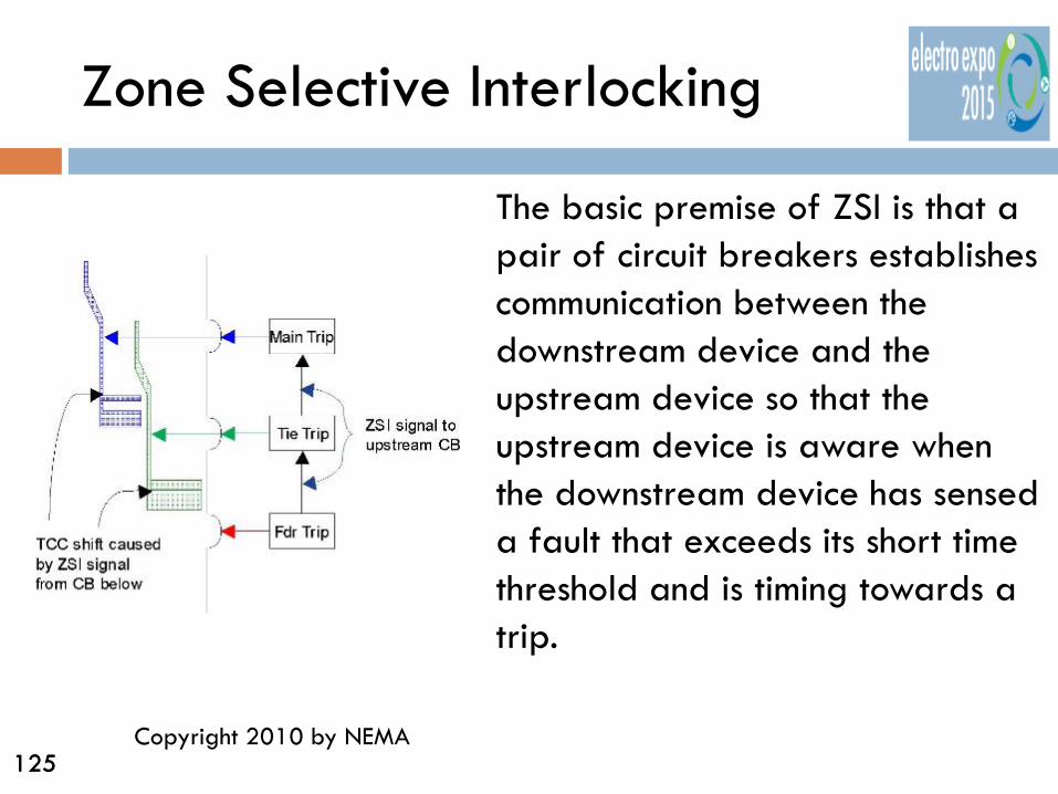
The basic premise of ZSI is that a pair of circuit breakers establishes communication between the downstream device and the upstream device so that the upstream device is aware when the downstream device has sensed a fault that exceeds its short time threshold and is timing towards a trip.
Copyright 2010 by NEMA

126 126
Zone Selective Interlocking
This information allows the upstream device to change its time delay setting to a slower time delay to allow the faster downstream circuit breaker to fulfill its protection role. (Ground Fault Zone Interlock protection is also readily available)
Copyright 2010 by Eaton

127 127
Zone Selective Interlocking
The upstream device operating at its slower setting provides suitable back-up protection in case the faster circuit breaker does not operate properly or does not clear the fault.
Copyright 2010 by NEMA

128 128
Zone Selective Interlocking
ZSI allows each circuit breaker receiving the ZSI signal to operate faster for faults within its respective zone of protection than it does when it is acting in a back-up role to downstream devices.
Copyright 2010 by NEMA

129 129
Simplified ZSI Communication Scheme
Different manufacturers may provide different ways to achieve this function. In most cases, however, the net result is very similar regardless of manufacturer. They react faster within the “in zone” protection settings.
Backup Protection
In Zone Protection
Copyright 2010 by NEMA

130 130
ZSI Communication Scheme
There are some limitations to ZSI applications in complex systems with multiple sources and tie circuit breakers. Manufacturers have different ZSI interconnection schemes and methods that may approach the complexities of multiple source systems differently.
131 131
Bus Differential Protection
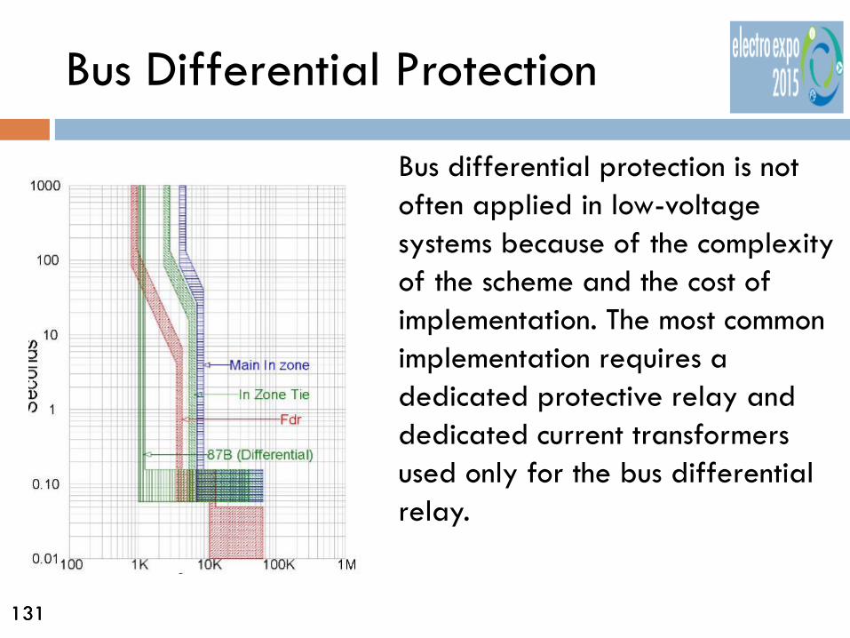
Bus differential protection is not often applied in low-voltage systems because of the complexity of the scheme and the cost of implementation. The most common implementation requires a dedicated protective relay and dedicated current transformers used only for the bus differential relay.

132 132
Bus Differential Protection
Bus Differential protection consists of a system that measures all the current into a zone and out of a zone. The sum of entering currents minus the sum of exiting currents should always equal zero. A non-zero quantity is indicative of current flowing outside of the expected circuit.

133 133
Field Adjustment
All the efforts that may go into designing a Selectively Coordinated electrical system will quickly be wasted if the Overcurrent Protective Devices (OCPD) are not properly set per the recommended settings from the coordination study.

134 134
Field Adjustment
Most manufacturers will, as standard practice, set their protective devices at the lowest, minimum pickup and trip time settings when they are shipped from their manufacturing factories. These minimum pickup and trip time settings are usually not in line with those recommended by the design engineer’s study.
135 135
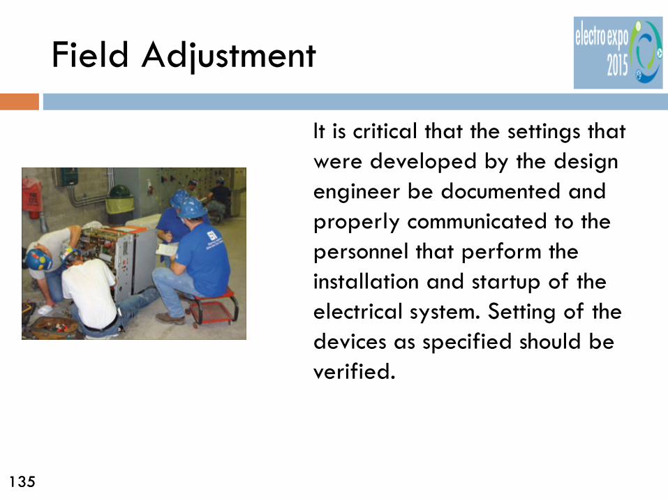
Field Adjustment
It is critical that the settings that were developed by the design engineer be documented and properly communicated to the personnel that perform the installation and startup of the electrical system. Setting of the devices as specified should be verified.
136 136
Lifetime Selective Coordination
If circuit breaker selective coordination tables or fuse ratio tables were used, to maintain the selective coordination throughout the life of the system, Overcurrent Protective Devices (OCPD) of that type and from that same manufacturer will always need to be used in that system.
137 137
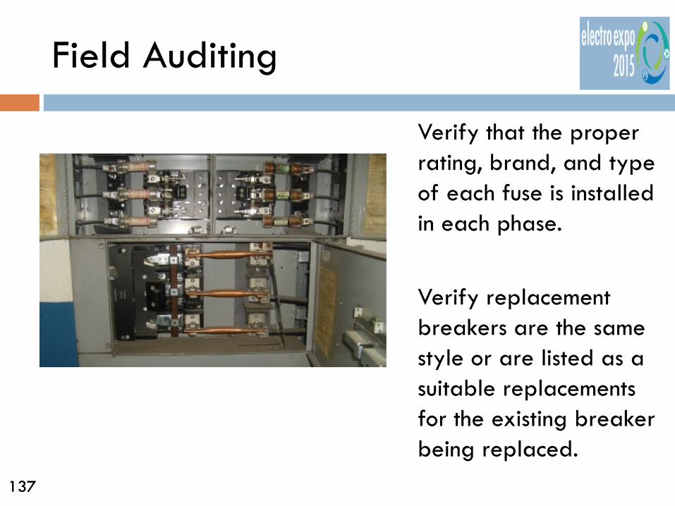
Field Auditing
Verify that the proper rating, brand, and type of each fuse is installed in each phase. Verify replacement breakers are the same style or are listed as a suitable replacements for the existing breaker being replaced.

138 138
Field Auditing
Routinely audit the electrical device settings to confirm that all existing circuit breaker and protective relay settings match the analysis studies.

139 139
Field Auditing
Owners should lock access to the circuit breaker adjustable electronic trip units and ground-fault pickup settings. Fusible switches should be field marked with the specific manufacturer and type of fuse to be installed in them.

140 140
Part 2 - Summary
1) Since 1984 coordination of all types of buildings was a requirement if a hazard would be created by a non-orderly shutdown.
2) The 2014 National Electrical Code has added the requirement for Professional Engineer to provide Selective Coordination to Hospital Essential Distribution Systems and Emergency Life Safety and Legally Required Systems.
3) Elevators and COPS electrical power systems remain required to be selectively coordinated.

141 141
Part 2 - Summary
4) Determine the Short Circuit Current at the devices being coordinated.
5) Work from lowest device from the utility source to upper device when completing a coordination study.
6) Adjustable trip breakers are available to better coordinate and limit arc fault currents in the overload and short time regions of the breaker trip curve.
7) Increasing the instantaneous setting of a breaker also increases the I2T energy and thus increases the arc flash energy.
142 142
Part 2 - Summary
8) Time Current Curves (TCC’s) are the traditional way used to show overcurrent device coordination but depend on graphically showing clearing times in the instantaneous region of a TCC.
9) Three alternate methods of coordinating in the instantaneous region of the overcurrent device includes: Impedance, Waveform Recognition and Zone Selective Interlocking.
10) These are common among manufacturers and are readily available to engineers, designers and installers.
143 143
Part 2 - Summary
11)Make sure to set the trip settings in the field according to the provided settings.
12) Lock adjustable trip mechanisms on breakers once set to prevent adjustment by unqualified persons.

144 144
Conclusion
End of Presentation Thank-You!