self-adaptation for internet of things applications
TRANSCRIPT

HAL Id: tel-01426219https://hal.inria.fr/tel-01426219v1
Submitted on 4 Jan 2017 (v1), last revised 13 Mar 2017 (v2)
HAL is a multi-disciplinary open accessarchive for the deposit and dissemination of sci-entific research documents, whether they are pub-lished or not. The documents may come fromteaching and research institutions in France orabroad, or from public or private research centers.
L’archive ouverte pluridisciplinaire HAL, estdestinée au dépôt et à la diffusion de documentsscientifiques de niveau recherche, publiés ou non,émanant des établissements d’enseignement et derecherche français ou étrangers, des laboratoirespublics ou privés.
Distributed under a Creative Commons Attribution - NonCommercial| 4.0 InternationalLicense
Self-adaptation for Internet of Things applicationsFrancisco Javier Acosta Padilla
To cite this version:Francisco Javier Acosta Padilla. Self-adaptation for Internet of Things applications. Computer Science[cs]. Université de Rennes 1, France, 2016. English. �tel-01426219v1�
ANNEE 2016
THESE / UNIVERSITE DE RENNES 1sous le sceau de l’Universit
´
e Bretagne Loire
pour le grade de
DOCTEUR DE L’UNIVERSITE DE RENNES 1
Mention : Informatique
Ecole doctorale MATISSE
presentee par
Francisco Javier Acosta PadillaPreparee a l’unite de recherche IRISA
Institut de Recherche en Informatique et Systemes Aleatoires
Self-adaptation forInternet of Thingsapplications
These soutenue a Rennesle 12 decembre 2016devant le jury compose de :
Emmanuel BACCELLICharge de recherche a INRIA Saclay/ Examinateur
Isabelle BORNEProfesseur de l’UBS/ Examinatrice
Johann BOURCIERMaıtre de conferences de l’Universite de Rennes 1 /
Co-directeur de th
`
ese
Didier DONSEZProfesseur de l’Universite de Grenoble 1/ Rapporteur
Stephane FRENOTProfesseur de l’INSA Lyon/ Rapporteur
Frederic WEISMaıtre de conferences de l’Universite de Rennes 1 /
Directeur de th
`
ese


A Mis padres
Francisco Javier Acosta Saludado y Alma Rosa Padilla Gutierrez

This work was partly funded by CONACyT, to whom I thank for their support andassistance during these 3 years.

ii

Acknowledgements
And here we are... at the beginning, but at the end...
After all these years, I have finally the space to thank all those persons who werewith me during this adventure. First of all, I would like to thank the jury members forreviewing the thesis, your comments helped me to achieve this work.
I would like also to thank my advisers, Frederic Weis and Johann Bourcier, who forall these 3 years supported me as much as possible, even when things seemed to bevery complicated to solve, they were there regardless of our own expertise (ELF loader,remember?).
Thanks too to my current team at Inria Saclay and Freie Universitat, you were alsovery helpful and important for me this last year.
Thanks to Emmanuel Baccelli, for understanding and giving me the time and advisesto finish this work.
I will also thank all the members of the DIVERSE team (formerly TRISKELL on myfirst year), who were also very helpful on several aspects, but especially to teach mea lot about informatics. Through all the coffees, seminars and office talks, I learned alot about you, about integrate myself as a foreign in this very open community whichwelcomed me with open arms. I will thank particularly Jean-Emile Dartois and IntiGonzalez for their very very precious help, without you guys, this thesis could not beachieved, THANK YOU!
But DIVERSE was not only about work, I must say that it was there where I met themost important and close people who were for me a primal professional support, butalso an invaluable personal support. Thank you again Jean-Emile, for being the veryfirst person who welcomed me and introduce me to the team, for teaching me aboutmodelling and informatics, to giving me your friendship. I’d like also to thank ErwanDaubert, who was always open and available to discuss (with a lot of patience) to aninformatics ignorant, who gave me lots of hints and knowledge about the business, butalso offered me his friendship. Thanks to Jose, Mai, Sana, Francisco, Inti, Ivan, Mauricio,Bosco, Marco, Natalia, Suresh, Aleks, Yannis, Dionysos, Ilias, Rima, Simon and all thosewho offered me their friendship, which was essential for me at all times. I’ll alwaysremember those barbecues, football matches, 4 esquinas matches (Marce! I don’t forgetyou!), and... yes, lots of parties!

iv
Special thanks to the Dr. Walter Rudametkin and his beloved wife, for giving metheir outstanding support. Marcia, Walter, ¡los quiero mucho!
Thanks to my family, who were always there in the good and the bad times, evenfrom far, I can feel your support.
Merci Maude!
Merci Celine!
Merci Elodie!
Thanks to all my Mexican friends in Rennes! (Special mention to Raıces Mexicanas...Sı senor!)
Danke schon mein Schatz!
Finally, thanks to all of you, you know who you are, you know how you helped me,and you know that everyone of you has a special place in my heart.
MERCI! GRACIAS! DANKE! THANK YOU!

Resume en francais
Nos vies quotidiennes sont entoures par de nombreux dispositifs qui embarquentdes unitees centrales de traitement (CPU) et une capacitee de stockage d’informations(memoire). Ces appareils jouent un role important dans nos activites quotidiennes, telsque les telephones intelligents [90], car nous les utilisons pour nous aider a accomplirde nombreuses taches (obtenir l’information de transport public en temps reel, meteo, e-mail, messagerie instantanee, etc.). En outre, d’autres types d’appareils prennent part dece nouveau monde numerique, car ils sont introduits sous forme de ”objets connectes”,qui sont destinees a communiquer non seulement avec les personnes par le biais des in-terfaces homme-machine, mais aussi a envoyer et recevoir directement des informationsprovenant d’autres objets similaires. En effet, les moyens de communication ont evoluedepuis l’introduction de l’acces Internet aux appareils autres que des ordinateurs, enutilisant la meme infrastructure et protocoles. Ce nouveau acces a Internet a apporte desnouvelles possibilites pour les dispositifs capables d’executer le protocole Internet stan-dard (IP). Cependant, ces nouveaux objets connectes ne sont souvent pas en mesure demettre en œuvre ce moyen standard de communication, en raison de leurs contraintesen puissance du processeur et de memoire, confiant leur moyen de communication auxdispositifs plus sophistiques (i.e. telephones intelligents, des tablettes ou des ordinateurspersonnels) visant un acces fiable a Internet.
L’Internet des Objets (IdO) vise a fournir une connectivite Internet a ces dispositifsa ressources limitees, en introduisant des protocoles plus efficaces tout en restant in-teroperable avec les protocoles internet actuels. En effet, ces nouvelles capacites de com-munication rendent ces objets accessibles de partout, maintenant capables de fournirdes services du type web. Par consequent, les objets faisant partie de l’IdO sont des-tines a offrir des services web d’une maniere standard, en tirant parti des API tels queREST [40]. Cependant, tres peu de services sur Internet sont destines a etre statiques.Au contraire, ils sont tres dynamiques et ont tendance a evoluer tres rapidement enfonction des besoins de l’utilisateur. Cela represente un grand defi dans l’utilisation dedispositifs contraints dans cet environnement, car ils ont ete concus pour executer dessystemes d’exploitation et des applications qui ne sont pas capables de fournir des car-acteristiques dynamiques. Ainsi, des nouveaux defis dans la recherche sur la facon dontces objets peuvent s’adapter aux nouvelles exigences apparaissent. En fait, l’adaptationdynamique des systemes logiciels est un domaine de recherche bien connu, et plusieursœuvres proposent des approches differentes pour fournir des solutions a ce probleme.Cependant, la plupart de ces solutions sont destinees aux machines non contraintes telles

vi
que les serveurs et plates-formes de cloud computing.
Les principales differences peuvent etre reconnues comme suit :
• Memoire : Kilo-octets au lieu de Giga-octets,
• Energie : Miliwatts au lieu de Watts et
• CPU : Megahertz au lieu de Gigahertz.
Motivations
Ce travail de recherche vise proposer un nouveau moyen de rendre possible le com-portement dynamique et des capacites d’auto-adaptation dans les dispositifs de l’IdO debord (class 2 [11] au maximum), en tenant compte de leurs ressources tres limitees dememoire et d’autonomie energetique . Les motivations de cette these se fondent dansla necessitee reelle de ces dispositifs d’etre hautement adaptables, puisque leur utilisa-tion peut varier de facon importante dans un court laps de temps. En effet, plusieursdomaines ont besoin du logiciel qui peut etre modifie en fonction de divers facteurs ex-ternes, tels que les Espaces intelligents (villes intelligentes, batiments, maisons, voitures,etc.). Ces environnements sont soumis au comportement humain, donc les exigencessur les informations necessaires a partir d’objets tels que des capteurs, et les actions ef-fectuees par des actionneurs, peuvent varier tres rapidement. Ainsi, le logiciel en coursd’execution sur ces appareils doit etre facilement modifiable, sans avoir besoin d’une in-tervention physique tels que le changement manuel de firmware ou le remplacement del’appareil.
Le cout en temps et en efforts pour changer le logiciel en cours d’execution dansles appareils faisant partie d’un espace intelligent peut etre tres eleve, et devrait etrereduit puisque les estimations sur la croissance des appareils dans l’IdO dans ces envi-ronnements est exponentielle, ce qui rend impossible d’adapter manuellement chaqueappareil. Par consequent, de nouvelles approches fournissant des mecanismes dedeploiement dynamique et automatique dans les environnements de l’IdO sont d’ungrand interet. En effet, ces efforts peuvent contribuer a la creation d’une infrastructureIdO envisageable, ce qui porte a une utilisation plus efficace de l’energie pour les ac-tivites humaines, ainsi que d’un mode de vie plus confortable.
Challenges
Cette these propose l’adoption des approches genie logiciel, et plus specifiquement,de l’ingenierie dirige par les modeles telles que les modeles en temps d’execution [77]pour gerer la tres grande couche logicielle presente dans un environnement IdO, en ten-ant compte des ressources limitees et l’autonomie energetique typique des dispositifs del’IdO.

vii
Les approches existantes provenant de la communaute du genie logiciel pour gererdes grandes plateformes logicielles distribuees et heterogenes, sont destines a leur util-isation sur des ordinateurs et des serveurs puissants, qui ne sont pas au courant del’utilisation de la memoire et de la puissance de traitement necessaire pour faire fonc-tionner leurs implementations.
En effet, l’IdO peut etre considere comme une plateforme logiciel distribuee, doncces approches de gestion sont a considerer pour leur adoption et mise en œuvre surles appareils de l’IdO. Cependant, la nature de ces dispositifs composant l’IdO differeextremement des machines sur lesquelles ces approches sont normalement mises en œu-vre. Les dispositifs IdO sont des nœuds tres contraints comportant quelques Ko en RAMet quelques centaines de ROM pour le stockage de programmes, ainsi que des petitesunites centrales fonctionnant a tres basses frequences.
Ainsi, les implementations directes des approches du genie logiciel ne peuvent pasrepondre a ces contraintes.
Les premieres difficultes rencontrees par ce travail de recherche, que l’on a reconnucomme des defis intra-nœud, peuvent etre resumees par les questions de recherche suiv-antes:
• QR1 : Est-il possible d’adapter une approche modeles en temps d’execution pourla gestion de la couche logicielle dans les environnements IdO?
• QR2 : Est cette approche assez petite en termes de memoire et d’utilisation duprocesseur pour permettre l’evolutivite?
En repondant a ces questions, nous pouvons continuer a explorer les possibilites of-fertes par l’utilisation des modeles pour gerer la couche logicielle des grands systemesdistribues. En effet, les modeles en temps d’execution proposent l’utilisation d’unmodele de composants pour permettre des fonctions d’adaptation sur la plate-forme encours d’execution, en modifiant le modele reflechi et en fait adopter ces modifications surle systeme sous-jacent. Ces modifications visent a affecter le cycle de vie des composantslogiciels afin de les adapter aux nouvelles exigences.
Ainsi, un troisieme defi peut etre mis en evidence pour son etude dans cette these:
• QR3 : Comment pouvons-nous decomposer un systeme informatique en com-posants logiciels et modifier son cycle de vie grace a un modele en tempsd’execution?
Enfin, comme la decomposition d’un systeme necessite la distribution des com-posants entre les nœuds concernes, une attention particuliere devrait etre mis au momentde les distribuer dans un reseau IdO. En effet, comme la topologie du reseau IdO manquede la robustesse et la bande passante trouvee dans les reseaux Internet communs, en rai-son des exigences de faible puissance pour les interfaces reseau, une enorme quantite detrafic pour la distribution des composants doit etre evitee. Ce dernier defi, la perspectiveinter-nœud, peut etre representee par la derniere question de recherche :

viii
• QR4 : Comment distribuer efficacement, deployer et configurer les composantslogiciels pour les appareils IdO.
Contributions
Le resultats de cette these sont deux principales contributions qui visent a fournir unmoteur d’execution des modeles en temps d’execution qui soit capable de reconfigureret de deployer des composants logiciels sur les environnements IdO.
Premiere contribution : Un moteur de modeles en temps d’execution representant uneapplication de l’IdO en cours d’execution sur les nœuds a ressources limitees. Latransformation du meta-modele Kevoree en code C pour repondre aux contraintesde memoire specifiques d’un dispositif IdO a ete realisee, ainsi que la propositiondes outils de modelisation pour manipuler un modele en temps d’execution. Cettecontribution repond aux questions de recherche 1 et 2.
Deuxieme contribution : decouplage en composants d’un systeme IdO ainsi qu’un al-gorithme de distribution de composants efficace. Le decouplage en composantsd’une application dans le contexte de l’IdO facilite sa representation sur lemodele en temps d’execution, alors qu’il fournit un moyen de changer facilementson comportement en ajoutant/supprimant des composants et de modifier leursparametres. En outre, un mecanisme pour distribuer ces composants en utilisantun nouvel algorithme appele Calpulli est proposee. Cette contribution repond auxquestions de recherche 3 et 4.

Contents
Acknowledgements . . . . . . . . . . . . . . . . . . . . . . . . . . . . . . . . . . . . . . . . . . . . . . . . . . iii
Resume en fracais . . . . . . . . . . . . . . . . . . . . . . . . . . . . . . . . . . . . . . . . . . . . . . . . . . . v
I Introduction
1 Introduction . . . . . . . . . . . . . . . . . . . . . . . . . . . . . . . . . . . . . . . . . . . . . . . . . . . . . . 11.1 Motivations . . . . . . . . . . . . . . . . . . . . . . . . . . . . . . . . . . . . . . . . . . . . . . . . . . . . . . . . 21.2 Challenges . . . . . . . . . . . . . . . . . . . . . . . . . . . . . . . . . . . . . . . . . . . . . . . . . . . . . . . . . 21.3 Contributions . . . . . . . . . . . . . . . . . . . . . . . . . . . . . . . . . . . . . . . . . . . . . . . . . . . . . . 31.4 Plan . . . . . . . . . . . . . . . . . . . . . . . . . . . . . . . . . . . . . . . . . . . . . . . . . . . . . . . . . . . . . . 4
II Background, context and state of the art
2 The Internet of Things (IoT) . . . . . . . . . . . . . . . . . . . . . . . . . . . . . . . . . . . . . . . . 92.1 The IoT at a glance . . . . . . . . . . . . . . . . . . . . . . . . . . . . . . . . . . . . . . . . . . . . . . . . . . 92.2 Towards an infrastructure for the IoT . . . . . . . . . . . . . . . . . . . . . . . . . . . . . . . . . 10
2.2.1 Overview of a smart city environment . . . . . . . . . . . . . . . . . . . . . . . . . . 102.2.2 A Building Automation use case: improving efficiency . . . . . . . . . . . 122.2.3 Devices used in Building Automation (BA) . . . . . . . . . . . . . . . . . . . . . 132.2.4 Communication between Building Automation devices . . . . . . . . . . . 152.2.5 Software for Smart Buildings . . . . . . . . . . . . . . . . . . . . . . . . . . . . . . . . . . 16
2.3 Current IoT solutions . . . . . . . . . . . . . . . . . . . . . . . . . . . . . . . . . . . . . . . . . . . . . . 162.3.1 A smart object approach . . . . . . . . . . . . . . . . . . . . . . . . . . . . . . . . . . . . . . 172.3.2 Communication between smart objects . . . . . . . . . . . . . . . . . . . . . . . . . 202.3.3 Overview of full IP stacks for Smart Objects . . . . . . . . . . . . . . . . . . . . . 242.3.4 All-in-one: IoT operating systems . . . . . . . . . . . . . . . . . . . . . . . . . . . . . . 252.3.5 Contiki . . . . . . . . . . . . . . . . . . . . . . . . . . . . . . . . . . . . . . . . . . . . . . . . . . . . . 252.3.6 RIOT . . . . . . . . . . . . . . . . . . . . . . . . . . . . . . . . . . . . . . . . . . . . . . . . . . . . . . . 28
2.4 Synthesis . . . . . . . . . . . . . . . . . . . . . . . . . . . . . . . . . . . . . . . . . . . . . . . . . . . . . . . . . 30

x Contents
3 Managing software deployment in distributed systems . . . . . . . . . . . . . . . 333.1 Overview . . . . . . . . . . . . . . . . . . . . . . . . . . . . . . . . . . . . . . . . . . . . . . . . . . . . . . . . . 333.2 Deployment of monolithic, homogeneous systems . . . . . . . . . . . . . . . . . . . . . 373.3 Deployment of non-monolithic, heterogeneous and distributed systems . . 38
3.3.1 Component Based Software Engineering (CBSE) . . . . . . . . . . . . . . . . . 383.3.2 Current deployment techniques . . . . . . . . . . . . . . . . . . . . . . . . . . . . . . . 433.3.3 Docker . . . . . . . . . . . . . . . . . . . . . . . . . . . . . . . . . . . . . . . . . . . . . . . . . . . . . 463.3.4 M@R in Dynamic Adaptive Systems (DAS) . . . . . . . . . . . . . . . . . . . . . 473.3.5 Kevoree as a flexible models@runtime approach . . . . . . . . . . . . . . . . . 50
3.4 Towards software deployment on the IoT . . . . . . . . . . . . . . . . . . . . . . . . . . . . . 513.4.1 Static deployment . . . . . . . . . . . . . . . . . . . . . . . . . . . . . . . . . . . . . . . . . . . 523.4.2 Dynamic deployment . . . . . . . . . . . . . . . . . . . . . . . . . . . . . . . . . . . . . . . . 53
3.5 Conclusion . . . . . . . . . . . . . . . . . . . . . . . . . . . . . . . . . . . . . . . . . . . . . . . . . . . . . . . 56
III Contributions
4 Models@Runtime for the IoT . . . . . . . . . . . . . . . . . . . . . . . . . . . . . . . . . . . . . . 614.1 IoT specific requirements for model@runtime . . . . . . . . . . . . . . . . . . . . . . . . . 614.2 Kevoree for the IoT . . . . . . . . . . . . . . . . . . . . . . . . . . . . . . . . . . . . . . . . . . . . . . . . 63
4.2.1 Minimal Kevoree properties needed on the IoT . . . . . . . . . . . . . . . . . . 654.2.2 Kevoree software implementation requirements . . . . . . . . . . . . . . . . . 68
4.3 Networking aspects on IoT environments . . . . . . . . . . . . . . . . . . . . . . . . . . . . . 704.4 Summary . . . . . . . . . . . . . . . . . . . . . . . . . . . . . . . . . . . . . . . . . . . . . . . . . . . . . . . . . 70
5 Intra-node challenges: middleware implementation and evaluation . . . . 735.1 An empirical study on constrained IoT devices . . . . . . . . . . . . . . . . . . . . . . . . 74
5.1.1 Kevoree-IoT: Estimating needed resources . . . . . . . . . . . . . . . . . . . . . . 745.1.2 Handling hardware constraints . . . . . . . . . . . . . . . . . . . . . . . . . . . . . . . . 755.1.3 Towards a new IoT device . . . . . . . . . . . . . . . . . . . . . . . . . . . . . . . . . . . . 77
5.2 The new Kevoree-IoT Contiki implementation . . . . . . . . . . . . . . . . . . . . . . . . . 785.2.1 An object-oriented representation using C . . . . . . . . . . . . . . . . . . . . . . 805.2.2 Model manipulation challenges . . . . . . . . . . . . . . . . . . . . . . . . . . . . . . . 82
5.3 Firsts evaluations of the approach . . . . . . . . . . . . . . . . . . . . . . . . . . . . . . . . . . . . 825.3.1 Requirements for large-scale evaluation . . . . . . . . . . . . . . . . . . . . . . . . 835.3.2 Extending the FIT IoT-Lab testbed . . . . . . . . . . . . . . . . . . . . . . . . . . . . . 84
5.4 Evaluation of Kevoree-IoT on the IoT-Lab testbed . . . . . . . . . . . . . . . . . . . . . . 895.4.1 Experimental overview . . . . . . . . . . . . . . . . . . . . . . . . . . . . . . . . . . . . . . . 895.4.2 Experimental setup . . . . . . . . . . . . . . . . . . . . . . . . . . . . . . . . . . . . . . . . . . 905.4.3 Scalability . . . . . . . . . . . . . . . . . . . . . . . . . . . . . . . . . . . . . . . . . . . . . . . . . . 91
5.5 Summary . . . . . . . . . . . . . . . . . . . . . . . . . . . . . . . . . . . . . . . . . . . . . . . . . . . . . . . . . 93

Contents xi
6 Inter-node challenges: distributing software artefacts . . . . . . . . . . . . . . . . 956.1 Inter-node challenges . . . . . . . . . . . . . . . . . . . . . . . . . . . . . . . . . . . . . . . . . . . . . . 966.2 Componentization of applications in the IoT . . . . . . . . . . . . . . . . . . . . . . . . . . 976.3 Calpulli: A distributed algorithm for component dissemination . . . . . . . . . 1006.4 Empirical evaluation . . . . . . . . . . . . . . . . . . . . . . . . . . . . . . . . . . . . . . . . . . . . . . 103
6.4.1 Use case . . . . . . . . . . . . . . . . . . . . . . . . . . . . . . . . . . . . . . . . . . . . . . . . . . . 1036.4.2 Experimental setup . . . . . . . . . . . . . . . . . . . . . . . . . . . . . . . . . . . . . . . . . 1046.4.3 Evaluation of power consumption . . . . . . . . . . . . . . . . . . . . . . . . . . . . 1056.4.4 Evaluation of deployment time . . . . . . . . . . . . . . . . . . . . . . . . . . . . . . . 107
6.5 Theoretical evaluation . . . . . . . . . . . . . . . . . . . . . . . . . . . . . . . . . . . . . . . . . . . . . 1086.5.1 Model of the IoT network . . . . . . . . . . . . . . . . . . . . . . . . . . . . . . . . . . . . 1086.5.2 Experimental setup . . . . . . . . . . . . . . . . . . . . . . . . . . . . . . . . . . . . . . . . . 1096.5.3 Evaluation results . . . . . . . . . . . . . . . . . . . . . . . . . . . . . . . . . . . . . . . . . . 1116.5.4 Conclusion . . . . . . . . . . . . . . . . . . . . . . . . . . . . . . . . . . . . . . . . . . . . . . . . 112
6.6 Conclusion . . . . . . . . . . . . . . . . . . . . . . . . . . . . . . . . . . . . . . . . . . . . . . . . . . . . . . 114
IV Conclusions and future work
7 Conclusions . . . . . . . . . . . . . . . . . . . . . . . . . . . . . . . . . . . . . . . . . . . . . . . . . . . . 1197.1 From IoT to MDE . . . . . . . . . . . . . . . . . . . . . . . . . . . . . . . . . . . . . . . . . . . . . . . . . 1197.2 Models@runtime to manipulate IoT software . . . . . . . . . . . . . . . . . . . . . . . . . 1207.3 Towards ”content caching” via Calpulli . . . . . . . . . . . . . . . . . . . . . . . . . . . . . 120
8 Perspectives . . . . . . . . . . . . . . . . . . . . . . . . . . . . . . . . . . . . . . . . . . . . . . . . . . . . 1238.1 Modelling tools for accurate code generation . . . . . . . . . . . . . . . . . . . . . . . . . 1238.2 A flexible component development framework . . . . . . . . . . . . . . . . . . . . . . . 1238.3 Leverage ICN mechanisms for efficient components distribution . . . . . . . . 124
Bibliography . . . . . . . . . . . . . . . . . . . . . . . . . . . . . . . . . . . . . . . . . . . . . . . . . . . . . . . 125
Abstract . . . . . . . . . . . . . . . . . . . . . . . . . . . . . . . . . . . . . . . . . . . . . . . . . . . . . . . . . . . 135
Abstract . . . . . . . . . . . . . . . . . . . . . . . . . . . . . . . . . . . . . . . . . . . . . . . . . . . . . . . . . . . 137

xii Contents

List of Figures
2.1 A Smart City deployment . . . . . . . . . . . . . . . . . . . . . . . . . . . . . . . . . . . . . . . . . . . . . . 112.2 Smart Building environment . . . . . . . . . . . . . . . . . . . . . . . . . . . . . . . . . . . . . . . . . . . . 142.3 Constrained vs. non-constrained device . . . . . . . . . . . . . . . . . . . . . . . . . . . . . . . . . . 192.4 CoAP Request from a node to another . . . . . . . . . . . . . . . . . . . . . . . . . . . . . . . . . . . 232.5 Comparison between Internet protocols stacks . . . . . . . . . . . . . . . . . . . . . . . . . . . . 242.6 Partitioning in Contiki: The core and loadable programs in RAM and ROM [31] 282.7 RIOT IP stack (from [54]) . . . . . . . . . . . . . . . . . . . . . . . . . . . . . . . . . . . . . . . . . . . . . . . 292.8 Evolution of computer systems (from [108]) . . . . . . . . . . . . . . . . . . . . . . . . . . . . . . 31
3.1 Components and their main characteristics . . . . . . . . . . . . . . . . . . . . . . . . . . . . . . . 403.2 OSGi Architecture . . . . . . . . . . . . . . . . . . . . . . . . . . . . . . . . . . . . . . . . . . . . . . . . . . . . . 423.3 Software Deployment Activities (from [52]) . . . . . . . . . . . . . . . . . . . . . . . . . . . . . . . 443.4 Trade-offs between distributed deployment approaches (from [99]) . . . . . . . . . . 443.5 Model@runtime principle . . . . . . . . . . . . . . . . . . . . . . . . . . . . . . . . . . . . . . . . . . . . . . 483.6 Deluge’s Data Management Hierarchy (from [60]) . . . . . . . . . . . . . . . . . . . . . . . . . 52
4.1 A M@R representation for IoT devices . . . . . . . . . . . . . . . . . . . . . . . . . . . . . . . . . . . 644.2 State-transition diagram showing the adaptation process in a typical Kevoree im-
plementation . . . . . . . . . . . . . . . . . . . . . . . . . . . . . . . . . . . . . . . . . . . . . . . . . . . . . . . . . 664.3 State-transition diagram showing the adaptation process for IoT devices . . . . . 674.4 The two different needs for a complete IoT models@runtime engine . . . . . . . . . 68
5.1 Graphical representation of a minimal M@R . . . . . . . . . . . . . . . . . . . . . . . . . . . . . . 755.2 The new designed board to meet our needs. . . . . . . . . . . . . . . . . . . . . . . . . . . . . . . 795.3 The FIT-IoT Lab M3 Open Node . . . . . . . . . . . . . . . . . . . . . . . . . . . . . . . . . . . . . . . . . 835.4 Memory overhead for 1, 2 and 3 Blink/COAP components. . . . . . . . . . . . . . . . . 92
6.1 Model@runtime principle . . . . . . . . . . . . . . . . . . . . . . . . . . . . . . . . . . . . . . . . . . . . . . 976.2 Kevoree component model . . . . . . . . . . . . . . . . . . . . . . . . . . . . . . . . . . . . . . . . . . . . . 986.3 Component model from the Kevoree meta-model . . . . . . . . . . . . . . . . . . . . . . . . . 996.4 Dissemination of software components using a DODAG . . . . . . . . . . . . . . . . . . 1016.5 State diagram describing a new component download, acting as a repository 102

xiv List of Figures
6.6 Energy consumption in the whole network for the given components . . . . . . . 1066.7 Time to deploy the selected components . . . . . . . . . . . . . . . . . . . . . . . . . . . . . . . . . 1076.8 Topology of the IoT-Lab M3 nodes at the Grenoble site . . . . . . . . . . . . . . . . . . . . 1086.9 Selected node as a Border Router with a maximum of 9 hops . . . . . . . . . . . . . . . 1096.10 Subset of reachable nodes from the sink . . . . . . . . . . . . . . . . . . . . . . . . . . . . . . . . . 1106.11 Theoretical RPL tree . . . . . . . . . . . . . . . . . . . . . . . . . . . . . . . . . . . . . . . . . . . . . . . . . . 1106.12 Number of retransmissions for 5 hops maximum . . . . . . . . . . . . . . . . . . . . . . . . . 1116.13 Number of retransmissions for 10 hops maximum . . . . . . . . . . . . . . . . . . . . . . . . 1126.14 Average cost per node for 5 hops maximum . . . . . . . . . . . . . . . . . . . . . . . . . . . . . 1136.15 Average cost per node for 10 hops maximum . . . . . . . . . . . . . . . . . . . . . . . . . . . . 113

List of Tables
2.1 Classes of constrained devices . . . . . . . . . . . . . . . . . . . . . . . . . . . . . . . . . . . . . . . . . . 202.2 Contiki general network stack with the corresponding netstack source codes ac-
cording to [19] . . . . . . . . . . . . . . . . . . . . . . . . . . . . . . . . . . . . . . . . . . . . . . . . . . . . . . . . 262.3 OS comparison (adapted from [6]). In this table, x represent no support, • partial
support and X fully support. . . . . . . . . . . . . . . . . . . . . . . . . . . . . . . . . . . . . . . . . . . . 29
3.1 Feature Comparison (adapted from [84]) . . . . . . . . . . . . . . . . . . . . . . . . . . . . . . . . . 55
5.1 Comparison between STM32F microcontrollers . . . . . . . . . . . . . . . . . . . . . . . . . . . 775.2 IoT Platforms comparison . . . . . . . . . . . . . . . . . . . . . . . . . . . . . . . . . . . . . . . . . . . . . . 785.3 Relocation types compatible with our loader . . . . . . . . . . . . . . . . . . . . . . . . . . . . . . 875.4 The architecture-dependent functions in the ELF loader . . . . . . . . . . . . . . . . . . . . 885.5 Memory use for the Blink/COAP example . . . . . . . . . . . . . . . . . . . . . . . . . . . . . . . 91

2 List of Tables

Part I
Introduction


Chapter 1
Introduction
Our everyday lives are surrounded by plenty of devices embedding central process-ing units (CPU) and information storage capacities (memory). These devices play animportant role in our daily activities, such as smart phones [90], as we use them to as-sist us on many tasks (public transport schedule information, weather, e-mail, instantmessaging and so forth). Moreover, other type of devices is taking part of these newdigital world, as they are introduced in the form of ”connected objects”, which are in-tended to communicate not only to people through human-machine interfaces, but alsoto directly send and receive information from other similar objects. Indeed, the commu-nications means have evolved since the introduction of internet access to devices otherthan computers, using the same infrastructure and protocols. This access to the Internetbrought new possibilities to the devices able to implement the standard Internet Protocol(IP). However, these new connected objects are often not able to implement this standardway of communication, due to its poor CPU power and memory constraints, relying thecommunication to more sophisticated devices ( i.e. smart phones, tablets or personalcomputers) aiming to reach the Internet.
The Internet of Things (IoT) aims to bring Internet connectivity to these resourceconstrained devices, by introducing more efficient protocols while being interoperablewith the current IP. Indeed, this new communication capacities make this objects reach-able from anywhere, now enabled to provide services in a web fashion. Therefore, objectsbeing part of the IoT are intended to offer web services in a standard way, by investingAPIs such as REST [40]. However, very few services on the Internet are meant to bestatic. On the contrary, they are highly dynamic and tend to evolve very quickly depend-ing on the user’s needs. This brings a big challenge for the use of constrained devices inthis environment, since they are supported by operating systems and applications thatwere not conceived to provide dynamic characteristics. Thus, new research challengeson how these objects can adapt to new requirements appear. In fact, dynamic adaptationon software systems is a well-known research area, and several works propose differentapproaches to provide solutions for this problem. However, most of these solutions areintended for non-constrained machines such as servers and cloud computing platforms.
The main differences can be recognized as follows:
2 Chapter 1. Introduction
• Memory: Kilobytes instead of Gigabytes
• Energy: Milliwatts instead of Watts
• CPU: Megahertz instead of Gigahertz
1.1 Motivations
This research work aims to propose a way to support dynamic behaviour and self-adaptation capacities on edge IoT devices (class 2 [11] as the biggest), taking into accounttheir very constrained resources on memory and energy autonomy. We motivate thisthesis by the real need of these devices to be highly adaptable, since their usage can varyin an important way in a short period of time. Indeed, several domains require softwarethat can be changed depending on various external factors, such as Smart Spaces (Smartcities, buildings, homes, cars, and so on). These environments are subject to humanbehaviour, thus requirements on the needed information from objects such as sensors,and actions performed by actuators, can vary very quickly. Thus, the software runningon these devices should be easily modifiable, without the need of physical interventionsuch as manual firmware change or device replacement.
The cost in time and efforts to change the software running on devices being part of asmart space can be very high, and should be reduced since estimations on the growth ofIoT devices in these environments are exponential, making impossible to manually adapteach device. Therefore, new approaches providing dynamic and automatic deploymentmechanisms on IoT environments are of high interest. Indeed, these efforts can makean IoT infrastructure a conceivable reality, bringing a more efficient use of energy forhuman activities, as well as a more comfortable lifestyle.
1.2 Challenges
This thesis proposes the adoption of Software Engineering approaches, and morespecifically, Model Driven Engineering approaches such as Models@Runtime [77] to dealwith the large software layer present in an IoT environment, taking into account theconstrained resources and energy autonomy typical of IoT devices.
The existing approaches coming from the Software Engineering community to man-age large, distributed and heterogeneous software platforms are intended for their useon powerful computers and servers, that are not aware of the memory usage and pro-cessing power needed to run their implementations.
Indeed, as the IoT can be considered as a distributed software platform, such manage-ment approaches are worth considering for its adoption and implementation on IoT de-vices. However, the nature of these devices composing the IoT differs extremely from themachines on which these approaches are implemented. IoT devices are very constrained

1.3. Contributions 3
nodes featuring few KB on RAM and some hundreds of ROM for program storage, aswell as small CPUs running at very low frequencies. Thus, direct implementations ofSoftware Engineering approaches cannot fit these constraints.
The first challenges faced by this research work, recognized by intra-node challenges,can be summarized on the following research questions:
• RQ1: Is it possible to adapt a model@runtime approach for the software layer man-agement on IoT environments?
• RQ2: Is this approach small enough on memory and CPU usage to allow scalabil-ity?
By answering these questions, we can continue to explore the possibilities given bythe use of models to deal with the software layer of large distributed systems. Indeed, themodels@runtime approach proposes the use of a component model to enable adaptationfeatures on the running platform, by modifying the reflected model and actually enactthese modifications on the underlying system. These modifications aim to affect thesoftware component’s life-cycle in order to adapt it to new requirements.
Thus, a third challenge can be highlighted for its study in this thesis:
• RQ3: How can we decompose an IoT system into software components and modifyits life-cycle through a model@runtime?
Finally, as decomposition of a system requires the distribution of such componentsamong the concerned nodes, special attention should be put when they are disseminatedin an IoT network. Indeed, as the IoT network topology lacks of the robustness andbandwidth found in common Internet networks, due to the low power requirementsfor network interfaces, a huge amount of traffic for components distribution should beavoided. This last challenge, the inter-node perspective, can be represented by our lastresearch question:
• RQ4: How to efficiently distribute, deploy and configure software components forIoT devices?
1.3 Contributions
The outcome of this thesis are two main contributions that aim to provide a completemodels@runtime engine able to reconfigure and deploy software components on IoTenvironments.
First contribution: A models@runtime engine able to represent an IoT running appli-cation on resource constrained nodes. The transformation of the Kevoree meta-model into C code to meet the specific memory constraints of an IoT device
4 Chapter 1. Introduction
was performed, as well as the proposition of modelling tools to manipulate amodel@runtime. This contribution answers RQs 1 and 2.
Second contribution: Component decoupling of an IoT system as well as an efficientcomponent distribution algorithm. Components decoupling of an application inthe context of the IoT facilitates its representation on the model@runtime, while itprovides a way to easily change its behaviour by adding/removing componentsand changing their parameters. In addition, a mechanism to distribute such com-ponents using a new algorithm, called Calpulli is proposed. This contribution an-swers RQs 3 and 4.
1.4 Plan
The reminder of this thesis is organized as follows:
Chapter 2 introduces the new paradigm of the Internet of things. It describes thecomposition of an IoT infrastructure and gives some examples of existing similar ones.Afterwards, we describe some current solutions aiming to support software deploymenton such infrastructures. Finally, a state of the art of the current IoT solutions and proto-cols is discussed.
Chapter 3 gives the definitions of software deployment on three contexts: on mono-lithic, homogeneous systems, on non-monolithic heterogeneous and distributed sys-tems, and finally on IoT systems. Moreover, it puts special attention on the benefitsof software decoupling in components, and presents an implementation example of thisdecomposition. In addition, it introduces the use of models@runtime along with a com-ponent model to support Dynamic Adaptive Systems, such as the IoT.
Chapter 4 presents our design and requirements towards an implementation of mod-els@runtime for IoT devices. It presents how the Kevoree approach, an implementationof the model@runtime paradigm, can be adapted for its use in constrained nodes, forwhich Kevoree was not initially designed. First, we take into account the challengesof adapting such implementation in very constrained nodes, the inter-node concerns,which are not able to run JVM or code interpreters. Second, since the networking ca-pabilities of these devices is also limited, we need to redesign the way this models willinteract with huge and constrained IoT networks, presented as the intra-node concerns.
Chapter 5 presents the intra-node challenges and introduces the minimal require-ments to run the previously designed models@runtime implementation, including thedesign of a representative IoT device meeting these minimal capabilities. Afterwards, animplementation running on a typical IoT Operating System is proposed and tested onour designed device, highlighting the main challenges of the implementation. Indeed,a large-scale method for testing is also important, thus the use of a testbed includinghundreds of nodes is proposed. Two critical needed missing features on the IoT testbedavailable for large scale experiments are presented, as well as the technical contributionsto provide such missing features. An evaluation of our models@runtime approach is

1.4. Plan 5
performed to show its feasibility and scalability on a large-scale IoT testbed.
Chapter 6 describes our final contribution, giving details about the software compo-nent decoupling of an IoT application, followed by the proposition of a new algorithmto distribute components taking into account the energy constraints and the inter-nodenetwork topology. Two evaluations of this algorithm, an empirical and a theoretical, areperformed to show its benefits.
Chapter 7 concludes this thesis by summarizing the results of our research and high-lights the benefits of using models@runtime on IoT environments to support dynamicbehaviour.
Chapter 8 gives several perspectives of future research related to this thesis.

6 Chapter 1. Introduction

Part II
Background, context and state of theart


Chapter 2
The Internet of Things (IoT)
The Internet of Things (IoT) is a paradigm to which we put more and more attentionin the scientific community [5]. Isolated pieces of the IoT are already present in every-day life, such as environmental sensor networks in streets, personal smart phones, RFIDtags in many retail stores, and so on. The existence of this devices is becoming impor-tant, since the services provided are now part of a new modern environment, facilitatingthe most common human tasks. This plethora of objects, or small computers, embedsoftware in many levels, from the very small sensor to smart buildings equipment. Re-garding the ubiquitous computing vision of Mark Weiser [110], modern cities are beingequipped with complex software deployments, to integrate plenty of new services, suchas traffic monitoring, instantaneous weather, public transport availability, food services,and so on.
This chapter aims at describing the current requirements of an Internet of Thingsinfrastructure, which represents our case of study. Moreover, these requirements willestablish a reference to state our research problems, based on a state of the art on currentmethodologies and approaches which aim to build such infrastructure. Indeed, a focuson a particular use case on building automation is performed, in order to highlight thecurrent challenges related to a network of connected objects, and its exploitation in formof distributed applications. All these requirements are then analysed to review the cur-rent approaches to provide connectivity between the most resource constrained devices,as well as their capacity to run complex software. We explain then why this features arean essential part of an IoT infrastructure. Finally, an overview of the current IoT OSs giv-ing these facilities is presented, as well as the application development and deploymentunder such OSs.
2.1 The IoT at a glance
Nowadays, the current Internet, or the Internet of people, is driven by a set of tech-nologies which were developed, extended and improved for the sake of human beings.These classical Internet technologies are those which are used, for instance, in com-
10 Chapter 2. The Internet of Things (IoT)
puters, tablets, smart-phones, smart TVs and streaming boxes, just to name a few. Usersreach this Internet in form of web pages, audio and video streaming, mobile applications,and so on. In the literature, these are called web services, which are provided from othermachines known as web servers. Web technologies are very well standardized, whichallows a direct use of web content for any device implementing such standards.
On the other hand, systems that do not provide direct communication to the user,but on the contrary, communicate exclusively with other machines, should use differentmeans to reach the Internet. For this, a new infrastructure that provides connectivity todevices of this kind is then necessary, and must leverage, as much as possible, existingframeworks to ease their integration and exploitation. That’s why the Internet of Thingsshould make use of different approaches, since the nature of their data and providedservices differ significantly from classical web services. The web of things [34] is thegoal to achieve for this new infrastructure.
2.2 Towards an infrastructure for the IoT
An IoT infrastructure can be defined as a set of interconnected objects that supplyone or more Internet protocols (IP), in order to exchange information about the tasks forwhich they were programmed, being part of a highly connected environment includingseveral and very different domains.
This infrastructure must be able to support connectivity and interoperability for ahuge number of devices of all nature, including, for instance, the services mentioned inthe introduction of this chapter §2. Furthermore, compatibility with the current Internetbasis should be mandatory, in order to take advantage of the robustness of the network.Large scale infrastructures featuring a huge quantity of heterogeneous participants ex-ists, and are being currently deployed. The smart city is one of the largest infrastructuresalready available, thus we can study its main properties and issues.
2.2.1 Overview of a smart city environment
In a smart city deployment [47], inhabitants can take advantage of the services de-rived from different interactions performed between each participant. This is what anIoT infrastructure aims to provide, making possible such interactions.
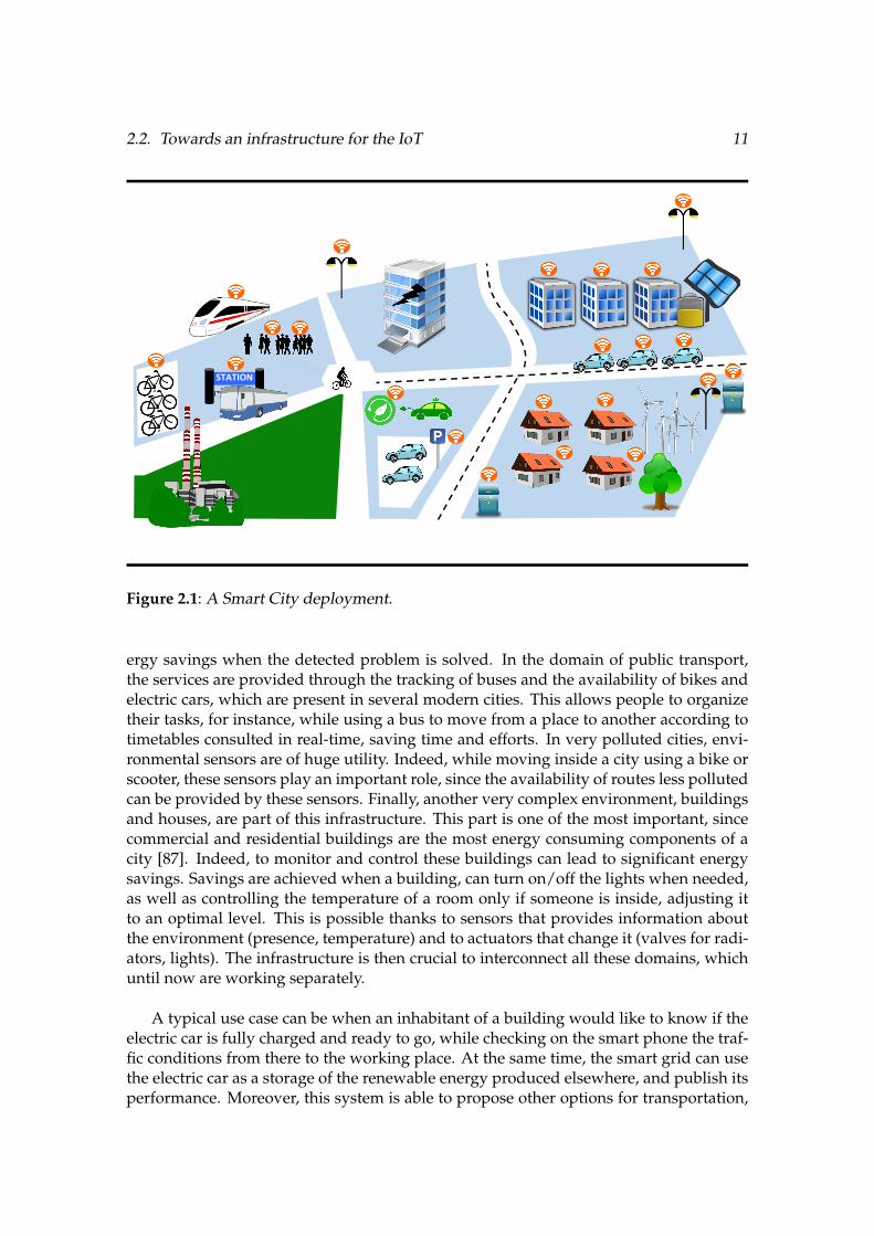
In figure §2.1 we can observe the diversity of participants and their very particularnature, which comes from small embedded environmental sensors to connected cars andsmart grids.
All the characteristics of this scenario can be decoupled by sectors. For instance, theelectricity network is being monitored and controlled by the smart grid [38]. This pro-vides a better understanding to the electricity consumption, which allows a fine controlof the production. Moreover, electricity leaks can also be found, resulting in instant en-
2.2. Towards an infrastructure for the IoT 11
STATION
Figure 2.1: A Smart City deployment.
ergy savings when the detected problem is solved. In the domain of public transport,the services are provided through the tracking of buses and the availability of bikes andelectric cars, which are present in several modern cities. This allows people to organizetheir tasks, for instance, while using a bus to move from a place to another according totimetables consulted in real-time, saving time and efforts. In very polluted cities, envi-ronmental sensors are of huge utility. Indeed, while moving inside a city using a bike orscooter, these sensors play an important role, since the availability of routes less pollutedcan be provided by these sensors. Finally, another very complex environment, buildingsand houses, are part of this infrastructure. This part is one of the most important, sincecommercial and residential buildings are the most energy consuming components of acity [87]. Indeed, to monitor and control these buildings can lead to significant energysavings. Savings are achieved when a building, can turn on/off the lights when needed,as well as controlling the temperature of a room only if someone is inside, adjusting itto an optimal level. This is possible thanks to sensors that provides information aboutthe environment (presence, temperature) and to actuators that change it (valves for radi-ators, lights). The infrastructure is then crucial to interconnect all these domains, whichuntil now are working separately.
A typical use case can be when an inhabitant of a building would like to know if theelectric car is fully charged and ready to go, while checking on the smart phone the traf-fic conditions from there to the working place. At the same time, the smart grid can usethe electric car as a storage of the renewable energy produced elsewhere, and publish itsperformance. Moreover, this system is able to propose other options for transportation,
12 Chapter 2. The Internet of Things (IoT)
since it is connected to the public mobility network, which provides real time informa-tion about buses, public bike availability, and so on. In addition, the user can also knowwhich are the conditions of air quality and temperature, using the smart city’s weatherservice. All this ”connected world” will bring many improvements to life quality, aswell as a better performance of energy consumption and production, which is a majorconcern.
The need of an IoT infrastructure which manages all these connections is then justi-fied, acting as a catalyst to provide new services. Traditional setups can actually offerservices such as availability of parking places in a mall, however, it is not possible toknow where the places are, nor to be reserved in advance. Connecting through the IoTthese two entities (a parking and a car) will allow to do it, resulting in efficient distribu-tion of traffic and time savings.
2.2.2 A Building Automation use case: improving efficiency
As stated in the previous subsection, buildings are of vital importance in a modernsmart city. These buildings offer several services to their inhabitants, such as Heating,Ventilation and Air Conditioning (HVAC), lighting, parking places and waste disposal,just to name the most common ones. Moreover, some buildings are able to produce theirown electricity, making use of Photo-Voltaic (PV) panels and small windmills.
Management of all this features must be done in all buildings in order to increase effi-ciency, and bring a more comfortable life to its occupants. Building Automation providesall the necessary pieces to support such infrastructure, making easier its administration.Furthermore, Building Managers supervise these buildings to refine settings and trackperformance. Thus, efficiency is the main challenge for Building Managers. The hu-man surveillance efforts in addition to management algorithms running on top of theautomation layer would deal with this challenge.
As residential and commercial buildings are the most energy consuming components[87] of a city, solutions to this important problem must be found. Moreover, nowadayswe are aware of the importance of natural resources, and the impact that waste andmisuse of these resources have in global warming, pollution and climate change. Thus,efficiency in resources usage is of vital importance. In order to cope with this situa-tion, new policies for resource savings must be enabled. To do that, a building needs tobe monitored with sensors and controlled through actuators. As we stated previously,these Building Management Systems (BMS) are built on top of many devices which arespread inside buildings. Plenty of different sensors, such as temperature, humidity, airquality, luminosity, etc., are exploited to gather different data that could be used instantlyto control or regulate a given service. Instant data such as presence and temperature, canlead to an instant reaction through actuators. For instance, when a presence is detectedin a corridor, ballasts are triggered to turn on the lights. Moreover, a room in whicha presence is detected and a very low temperature is sensed, an actuator will immedi-ately open a valve to heat the place. In addition to the instant energy savings given bysuch actions (turn off the lights when nobody is in a room and reduce the heating), the

2.2. Towards an infrastructure for the IoT 13
need of more versatile sensors and actuators embedding IoT technologies comes withthe evolution of services, in which a simple sensor can embed algorithms to predict theideal temperature conditions to save even more energy, by analysing data coming froma weather station or even anticipate the occupant’s arrival by getting information fromhis car.
This scenario is only possible if an infrastructure composed of all the features de-scribed above is deployed in current buildings, as well as fitted by default in new onesto be IoT ready. Let’s take the example of an old building that is being refurbished tomeet the new energy consumption requirements. First of all, the building must be anal-ysed A sensor deployment is then necessary to find its current performance and the partsthat need urgent attention, like structural damages or thermal leaks. Once the informa-tion is gathered and the possible reparations are done, a second step is to replace all theprevious sensors, or their firmware, for new ones, which will perform the supervisionand control of the new added features. This building which already have sensors and ac-tuators, can change its use and consequently its behaviour For instance, a complete floorfull of offices that changes its occupants, from a logistics enterprise to a governmentagency. A complete change in the policies for the services provided by the building willbe needed, forcing the deployment of new configurations for all sensors and actuatorsthat could be present in the floor, such as new access controls, HVAC requirements andparking assignment, just to name a few. With this very changing conditions, buildingscannot be efficient if the automation is done in such a statically way, and even less if thebuilding continue to be unaware of external events.
Thus, the IoT find its place in the applications cited previously, since in addition toprovide connectivity to the rest of external entities (sources of information), it can lever-age the full capacities of the devices deployed in buildings to expose its own services.Indeed, a building with such capabilities can enable the evolution of its services, allow-ing to be updated or new ones to be added. Special attention must be put in the designof devices needed to perform these new tasks, in which the IoT capabilities will be de-ployed, since they should be ready for more dynamism, e.g. provide plug and playsensors and actuators.
Next Subsection will give an insight about the current deployed devices, and howthey evolve according to new needs.
2.2.3 Devices used in Building Automation (BA)
A building must be equipped with sensors and actuators that make possible to su-pervise and control its services, which were already mentioned above. This is known asBuilding Automation (BA). Small, lightweight and often battery powered, these sensorsand actuators need components that should be cheap and robust, since some environ-ments can be difficult to access or require special installation [113]. The fact of beingpowered by batteries adds much more flexibility of placement, since they can use wire-less communications, sacrificing autonomy. Thus, a BA device must offer a maximumof autonomy to avoid maintenance costs (i.e. frequent battery replacement), which can

14 Chapter 2. The Internet of Things (IoT)
be costlier than wiring up such device. Most battery powered devices are sensors ratherthan actuators, which are less numerous in buildings. In a different way, actuators are of-ten forced to be wired, since it is complicated to use batteries for high energy consumingtasks, such as motor control for valves or blinds, for instance. On the other hand, ac-tuators like lighting ballasts or ventilation engines are inherently connected to the mainbuilding’s electricity network, thus, they do not present autonomy issues. One inter-esting approach to increase self-sufficiency is the use of energy harvesting [51]. Thesedevices are able to run without batteries or cables, since they are equipped with energyharvesters which produce their own energy. Indeed, energy harvesting can be doneby mechanical effort (i.e. pushing a switch), through small solar panels, or even withthermocouples. Many devices of this kind are available on the market from lots of man-ufacturers, and specialized enterprises are in charge of their deployment. In the mostcommon cases, this work consists on the physical installation, configuration and tests ofthe functionalities which are preloaded by devices’ manufacturers.
We can now depict in figure §2.2 the hierarchical organisation on which our previ-ously described IoT devices are placed, showed as IoT technologies and Smart Objects.
Structured, open, well-documented, accessible data
Parkingmanagement
Energymanagement
Wastemanagement
Comfortservices
Activity analysis
Assetsmanagement
Removal management
IP
CLOUD
Services EvolutionBuildingAutomation (BA)PLCs
IoTTechnologies
Supervision
BA field buses (KNX, LonWorks, EnOcean, ModBus, etc.)
Smart Objects
Figure 2.2: Smart Building environment.
Indeed, we found in the first place the common sensors present in a building, suchas temperature, humidity, luminosity, gas, and so on. It also includes all meters likeelectricity, water and gas, which are the common services available in a building. Inaddition, this layer contains all the necessary actuators to control these services, the mostcommon being valves for heating, dampers for ventilation, lights, blinds, and so on.Afterwards, there is an automation layer, which obtains the instantaneous data coming

2.2. Towards an infrastructure for the IoT 15
from sensors and meters that, following the programmed algorithms in a ProgrammableLogic Controller (PLC), execute actions i.e. open/close a valve or turn on/off lights. Asupervision layer then store all the generated data locally, to provide visualizations of thestate of the building, either present or past. Supervisors are often deployed in industrialPCs, servers, or another high-end computer. This is required due to the very complexdata processing needed to represent all the functional features present in the building, aswell as a very rich dynamic visual imagery offered to buildings managers.
Once a deployment of this kind exists in a building, we can define it as a SmartBuilding. In this new environment, we can found several technologies that require manyskills and players, since complexity is divided in different levels.
A deep change in these devices is then needed in order to meet the new require-ments that IoT connectivity imposes. Indeed, ”intelligence” cannot be achieved with theexisting sensors and actuators by themselves, entrusting this activity to more sophisti-cated components. This adds lots of complexity which is difficult to manage, and can beavoided if it is distributed to the devices of the first layer. Replacement of this layer withnew devices which are able to process much more information than the current ones willbe needed, facilitating the implementation of IoT communication protocols.
2.2.4 Communication between Building Automation devices
While sensors and actuators can send and receive data, it must be transmitted usinga specific communication way. In this context, wired solutions provide a very robust andsafe way to transmit data between devices being part of a smart building. Indeed, theneeded communication protocols require only a very small bandwidth, since the mes-sages coming from sensors are, by definition, very short (i.e. a temperature measure).However, sensors are often needed in places which can be predefined, in order to pro-vide a more accurate sensing. This becomes a problem when wires are difficult to install,due to the possible routing through walls and ceilings. Several devices can use wirelesscommunication to transmit their data directly to actuators, through a process called pair-ing and commissioning. This is very useful when instant data is needed, i.e. a presenceto turn on lights. However, wireless communications need a certain quantity of energyto transmit radio waves over the air, and sensors equipped with wireless transceivers areoften battery powered. Thus, energy consumption for data sharing is important. Fortu-nately, the small size of the data messages that come from sensors needs a very shortcommunication time, allowing a small energy consumption. Moreover, batteries shouldlast as long as possible, sending data periodically (i.e. one message every 30 minutes orso) with no need of acknowledge or feedback.
This communication approaches can be reused as is, in an IoT infrastructure, sincethe physical medium used to transmit messages is the same. However, a more detailedenergy management for wireless devices will be needed, since IoT protocols are morecomplex and could increase the network traffic.

16 Chapter 2. The Internet of Things (IoT)
2.2.5 Software for Smart Buildings
All the infrastructure described above is able to produce many important data. Newservices can be provided if all these data are analysed, then structured to give a betterunderstanding to end users. Typical exploitation of this services are, for instance, smart-phone or tablet applications that can display a building behaviour, using historical data.Furthermore, devices can be controlled remotely using this kind of applications, i.e. turn-ing on/off a light using a phone or a remote computer. Alerts of unexpected buildingbehaviour are also very useful, thanks to a software layer that can be used to send SMSto notify about an event of this kind. These new services need a software managementthat must run inside the building, either using computers, PLC, or other type of central-ized server. IoT devices will need to embed this kind of services in a distributed way. Itmeans that access to the instant data and, in the best case, a minimum of historical data,is needed from the devices itself, being independent of centralized servers.
Therefore, an important effort in software development is needed in all levels of aBA deployment. From embedded software to supervision engines, the presence of algo-rithms which manage the low-end devices information, such as sensors and actuators,are required to provide an easy to use interface between all the participants. Indeed,reconfiguration and deployment of new software for these devices is also useful to fol-low the building’s evolution of services, such as environmental data, parking control,lighting status and so on, typical of a smart building. Thus, a transparent way to accessservices directly from the sensors and actuators could be the most efficient approach.Moreover, allowing a direct communication at this level would enable access to the con-figurations and embedded software already installed, offering a remote way to makemodifications. With a deployment of this kind, interoperability between the other actorsin a smart city should be easier, by using standard protocols. Indeed, standardization ofprotocols for BA and other city services will be needed, in order to take advantage of thesoftware capabilities provided directly by sensors and actuators.
2.3 Current IoT solutions
As described in the previous section, a smart city will include plenty of services com-ing from very different providers. Depicted in figure §2.1, the heterogeneity betweenactors in a smart city requires software development for different platforms. Indeed,development environments can differ drastically from a scenario to another. Followingthe example given previously, the smart building is one of the main sectors which needmore attention, since energy savings can be more considerable than any others. Newbuildings must be equipped with all the necessary IoT infrastructure already describedin the preceding sections, in order to be efficient. However, the current issue consistsin upgrading existing buildings to this new claims. This is very challenging, since clas-sical solutions for BA are developed in a statically fashion, without taking into accountthe future evolutions that can be performed on buildings. Furthermore, the very com-plex deployment of these systems make their adoption very costly, since configurationand further changes must be made by experts. Existing deployments in some cities can

2.3. Current IoT solutions 17
provide similar services as stated above, but the current complexity of the existing infras-tructure makes its exploitation very complicated. In order to ease and enable all thesenew capabilities, a new infrastructure based on the IoT must be proposed. As statedin subsection §2.1, web services are the most common way to share web content in theclassical Internet. Thus, providing web APIs relying in the IoT are essential. Indeed,the deployment of these new features could be very difficult, since the heterogeneity ofthe participants complicates the development of standard communication protocols andcross-platform web applications.
Solutions that come from the Information and Communication Technologies (ICT)field will be studied throughout this thesis, in order to find a new way to develop, deployand maintain this IoT infrastructure. In particular, the research done in Software Engi-neering (SE) could be useful to propose new solutions to the issues mentioned above,since solutions for distributed systems, which are very close to the IoT environment,have been studied since long time by this branch. For instance, Meta-Modelling frame-works are already used to perform smart grid data analysis [57], which seems to be veryconvenient and efficient. This approach offers an abstraction level that is easier to under-stand and manipulate, hiding the complexity of the underlying software infrastructurewhich is more difficult to manage by hand. Therefore, smart objects participating inthe IoT embedding middleware which provide these abstractions would ease the task ofmanaging software deployment and its evolution.
2.3.1 A smart object approach
Most of the devices used in BA are built using microcontrollers (Microcontroller Unit,MCU), since they are very cheap components which can easily be programmed to per-form small measurements or activate actuators, as well as implement one or more com-munication protocols. However, current communication between BA devices make useof field buses implementing protocols which are often proprietary, thus adaptability atthe firmware level is almost impossible. While reconfigurations are possible, the verycomplex protocols make this task very difficult, much more when equipment from dif-ferent constructors is present. Indeed, current BA deployments seem to be very difficultto adapt and reconfigure, thus a new smart object approach should be proposed. Sincethe most viable way to allow evolution of services resides in the adaptation capabilitiesof low-end BA devices, the research efforts on this thesis will be conducted to this par-ticular case. Therefore, the needed hardware for these smart objects should be as genericas possible, since changes on their behaviour by reconfiguring them or deploying newsoftware services are necessary. The Internet of Things is then the mean to reach thesedevices, using standard Internet protocols. However, embedding evolution capabilitiesinto this kind of devices is not an easy task. Indeed, developing software for embeddedsystems due to their constrained computational resources is already difficult, while de-ployment of this software is also challenging since the quantity of devices could be verylarge to perform it manually. A study on these low-end devices’ constraints is performedin the next Subsection.

18 Chapter 2. The Internet of Things (IoT)
2.3.1.1 Focusing on constrained devices
As explained in subsection §2.2.3, the lower layer of a BA infrastructure shown in fig-ure §2.2 is composed of devices which have low cost, flexible placement and rapid soft-ware development as their main features. Since the goal is to enhance these devices withweb features, a new BA layer must be proposed to replace the existing one, in which webservices could be deployed. However, due to the constrained computational resourcesof these objects, classical implementations of Internet protocols cannot be deployed onthis constrained environment. We highlight classical because interoperability betweenobjects is easier to achieve using the Internet infrastructure that already exists.
The available resources will depend on the function that the object was intended toperform, and will also be driven by a specific placement and connectivity. The usageof these objects can be very diverse, from common sensing/actuating tasks (tempera-ture, humidity, air quality, HVAC, access control) to small algorithms that provide basicfunctionalities, such as thermostats, coffee machines, traffic monitors, and so on. For in-stance, objects used for environmental sensing applications often need to be installed ata specific place [113], which can be hard to reach. This forces to either reach the sensorswith a specific cable, for both power and network connectivity, or use wireless commu-nications. On the other hand, for devices typical of home appliances or smart meters,the placement is often already defined, thus they can be easily connected to an existingnetwork.
For the first kind of applications mentioned above, wireless communications seem tobe very convenient, while in the second example, a wired connection can already exist orcould be easy to provide. The communication method will determine the way we powerthe device, either using batteries or the electricity network. Thus, two kind of objectswith different hardware capabilities can be present in this IoT infrastructure, which wecan separate into:
• Constrained devices( i.e. [59]). These are battery powered wireless devices whichhave no more than 1MB of RAM and 2MB of ROM (program data), offering a veryefficient energy management. The mono-core CPU clock runs at less than a hun-dred megahertz.
• Non-constrained devices(i.e. [42]). Wall-powered System on a Chip (SoC) devicesembedding several megabytes of RAM (hundreds or thousands), having an exter-nal storage for program and user data. Connectivity is often achieved by a wiredEthernet interface. Its CPU can run at several hundred megahertz, which resultsin a high-power consumption. Multi-core versions also exist, which increase evenmore the energy consumption.
Non-constrained devices are often able to run modern implementations of Internetprotocols, since the hardware capabilities provided by objects powered by the electricitynetwork are usually high. On the other hand, constrained devices, which are often bat-tery powered, does not provide enough computational resources to implement current

2.3. Current IoT solutions 19
Internet protocols as is. However, they provide more flexibility of installation, due totheir physical size and cost.
● ARM® 32-bit Cortex®-M3 CPU● 72 MHz maximum frequency,
1.25 DMIPS/MHz● 512 Kbytes of Flash memory● 64 Kbytes of SRAM● NOR Flash 128Mb
The M3 open node The Raspberry Pi model B
● 700 MHz ARM11 ARM1176JZF-S core● Broadcom VideoCore IV,OpenGL ES
2.0,OpenVG 1080p30 H.264 high-profile encode/decode
● SD card up to 64GB● 256MB of SDRAM
Figure 2.3: Constrained vs. non-constrained device.
Figure §2.3 shows a resource comparison between these two kind of objects. We canhighlight the big difference between them, as much in memory as in processing speed.While the price and the resources of SoC systems is very attractive, power consumptionstill a main drawback. Such kind of devices would not last a day running on smallbatteries, since the big amount of memory and the high-speed processor are very powerconsuming.
The Internet Engineering Task Force (IETF) working group light-weight implemen-tation guidance (lwig) proposes a classification in the RFC7228 [11], which separatesconstrained devices into classes, as shown in table §2.1. For instance, objects such as theM3 open node [59], are considered the upper limit of a constrained device, being of class2, which is a reference in this thesis as an IoT platform for experimentations.
The very low-cost of MCU based objects, coupled with their very low-power capabil-ities, make them very easy to produce and could be spread in most of physical environ-ments, such as forests, streets, buildings and homes, since it is possible to make them runin batteries. Moreover, its computational capacities offer enough processor speeds andvery complete instruction sets that make them suitable for the deployment of algorithmswith considerable complexity. In this thesis, we will put emphasis on MCU based smartobjects [67], since most of the scientific challenges come with the constrained resourcesin memory and energy of such devices.

20 Chapter 2. The Internet of Things (IoT)
Name data size (e.g., RAM) code size (e.g., Flash)
Class 0, C0 <<10KiB <<100 KiB
Class 1, C1 ⇠ 10 KiB ⇠ 100 KiB
Class 2, C2 ⇠ 50 KiB ⇠ 250 KiB
Table 2.1: Classes of constrained devices.
2.3.1.2 The very constrained nature of MCU based smart objects
Web technologies are nowadays well investigated and offer many tools for fast de-velopment and maintenance, however, they rely on modern equipment: fast micropro-cessors with many cores, gigabytes of RAM and several terabytes in hard disks. Whilecomputers, mobile phones, and similar devices grow constantly in computing capacities,for microcontrollers the evolution is much less evident.
One of the main reasons for this slower evolution, is the cost of MCUs. In orderto maintain a very low price for these devices, their size should be kept small. SinceSRAM (the volatile memory type used in MCUs) takes a lot of space in the chip, it is notpossible to add more without increasing the cost of the chip, which is not wanted in avery competitive market as MCUs is. In addition, the fabrication process of MCUs differsin many ways in comparison to SRAM construction. Thus, for semiconductor foundriesa complex device fabrication leads to an increased cost. Finally, as stated in section §2.2,the flexibility in the placement of IoT devices is a major concern. SRAM being veryenergy consuming, it wouldn’t be possible to power large SRAM devices using batteries.Therefore, to summarize, the construction of MCUs with huge quantities of memory isnot economically and energetically viable.
2.3.2 Communication between smart objects
A smart city includes a wide range of devices that differs, mainly, in their commu-nication capabilities. For instance, networks already deployed in smart buildings makeuse of particular technologies, as known as BA protocols. This kind of infrastructureis able to communicate using IP protocols, implemented at the automation layer. Mostof BA PLCs provide IP implementations out of the box, either as a gateway (KNX/IP,LonWorks/IP, BACNet/IP, etc.) [63] or using proprietary modules available from theconstructors. Thanks to this, the upper layers can access, in a ”web fashion” (i.e. usingOPC, oBIX, etc.) [83], to all this data in order to perform web-based manipulations. Re-search done in this area has interesting results [62], but the approaches are often basedon gateway developments, which implies additional software and hardware. This alsocomplicates the evolution of this services, since the required data provided by the lowerlayers depends on the configurations and embedded software provided from the first de-ployment. Moreover, leveraging web capabilities is the main goal of the communication
2.3. Current IoT solutions 21
layer, thus an Internet based solution must be proposed at the lower layer.
2.3.2.1 Internet based approaches
Several communication protocols are used in the classical Internet. Most of them arebased on Ethernet [3], in which a standard cable is needed for each participant in thenetwork. A wireless Ethernet protocol was also standardized, known as IEEE 802.11 [2],providing the same features without the need of cables. Other ways to reach the currentInternet also exists, such as optical fibre, satellite and different radio standards, just toname a few.
Since the IoT aims to be ubiquitous, communication using cables would complicatethe physical installation of such objects. Indeed, the main advantage of MCU basedobjects is their very low power consumption. Thus, a very low power communicationinterface would allow these objects to be powered using batteries. Therefore, wirelesscommunication protocols seem to be the best choice. However, communication inter-faces implementing standards i.e. IEEE 802.11, were not built having low power fea-tures in mind, making them too inefficient if batteries are used as power source. Severalwireless devices manufacturers and research institutes worked together to create newenergy-aware protocols to provide wireless communication for smart objects. One of thestandards that came from these efforts is the IEEE 802.15.4 [1]. The latter was createdspecifically for low-power transceivers, allowing communication ranges near to 802.11,but offering a very low bandwidth. This limitation avoids the exchange of large datapackets, which also limits the protocols that can be managed by the interface, beforehaving considerable fragmentation. Moreover, the protocol supports communicationsin various topologies, such as star, ring, and mesh, while the latter is the most used,since every device can act as a router, overcoming the range limitations. However, usinga complex topology reduces the reliability of the network, thus the implementation ofacknowledge messages in almost all layers is necessary.
On the other hand, the memory constraints present in MCUs avoid the use of classicalapproaches to develop software for web based applications, often written with high levelprogramming languages. These approaches make use of common Internet protocol’simplementations, which are not aware of this low resources. Thus, a new way to provideInternet functionalities must be developed.
In 2003, Adam Dunkels developed a very lightweight TCP/IP protocol stack, uIP[27], for 8-bit microcontrollers, enabling smart objects to communicate using a standardInternet protocol. With this contribution, several services could be developed to createa first IoT infrastructure. However, most of the services provided in classical Internetdoes not use a simple way to communicate, such as TCP/IP. Therefore, a more com-plete framework for web services development should be created, to establish a moretransparent and easy to use approach for resource constrained devices.

22 Chapter 2. The Internet of Things (IoT)
2.3.2.2 6loWPAN, or how to give an IP address to any object
With the arrival of the IPv6 standard [24], which enabled a wider range of IP ad-dresses than the previous IPv4, the possibility to assign an address to each smart objectbecame a reality. This brings new challenges in the implementation for this new net-work protocol in smart objects, since the RFC2460 [24] specification was intended forhigh resources machines.
Montenegro et al. proposed a new specification [76] for constrained resources de-vices in order to communicate using IPv6 addresses. This specification, called 6loWPAN(IPv6 for low-power Wireless Personal Area Networks) was successfully implemented[35] and was able to provide interoperability with IPv6 ready devices, as it fulfilled allthe requirements to have an IPv6 label†1. The main feature of the loWPAN adaptationlayer is the compression of the IPv6 header, along with fragmentation and mesh address-ing features.
Thanks to 6loWPAN compression, we have a first ”Internet of Things” approachwhere every smart object can be reached from anywhere on Internet. This enables the de-velopment of web services, since the objects themselves can already be part of a networkwhere they can offer their embedded services, hosted in their small amount of memory.A new way to represent this services is then required, that could meet the current webservices specifications and approaches.
2.3.2.3 Application layer for smart objects
In the classical Internet, web services are very often represented using the HTTPapplication protocol [39], in an architectural style called REST (REpresentational StateTransfer), defined by Fielding and Taylor [40]. Technically, REST consists of a coordi-nated set of components, connectors, and data elements within a distributed hyperme-dia system, where the focus is on component roles and a specific set of interactions be-tween data elements rather than implementation details. Indeed, a REST API aims toprovide a way to access services with high performance, scalability, simplicity, modifia-bility, visibility, portability, and reliability. RESTful services are very useful in the web,since they have a very easy way to operate with HTTP using simple verbs: GET, POST,PUT, DELETE, just to name the common ones. This representation could be also use-ful for smart objects, allowing the user, or other smart objects, to access its services in astandard way, providing interoperability with a good abstraction level.
While an implementation of HTTP is conceivable for smart objects, the huge amountof memory in both RAM and ROM turns it too heavy and inefficient to run on con-strained, battery-powered devices [92]. To solve this problem, Shelby et al. standardizedthe ”HTTP for resource constrained devices” [91], called CoAP (Constrained ApplicationProtocol). This new application protocol is able to manage the methods described above,fulfilling the requirements for a RESTful API.
†1https://www.ipv6ready.org/

2.3. Current IoT solutions 23
Border Router
Radio
MCU
Peripherals
SLIP
GE
T /s
en
sors
/tem
pe
ratu
re/
coap://m3-1/
Radio
MCU
Peripherals
coap://m3-2/
Radio
MCU
Peripherals
coap://m3-3/
Radio
MCU
Peripherals
Figure 2.4: CoAP Request from a node to another.
Figure §2.4 shows a typical CoAP request, on which only 13 bytes are needed toformat this message, leaving around 90 bytes for payload in a single 802.15.4 frame.Moreover, we can observe that a ”SLIP” connection exists between the Border Routerand a computer. This SLIP connection, acronym of Serial Line Internet Protocol, serveas a bridge between the radio communications and a wired network connection to theInternet. By these means, nodes behind a Border Router can be accessed from anywhereon the Internet, and more specifically, by using the CoAP protocol.
The services provided by the smart objects can be represented in a HTTP like form,i.e. on figure §2.4 the node with the address coap://m3-2/ is asking for the temper-ature resource /sensors/temperature to node coap://m3-3/. By using the CoAPcommand GET for this resource, we should have a response similar to ”22.5”, as an ex-ample of resource representation. On the other hand, the PUT and POST commandsare used to change the state of the actuators that can be present in a smart object. Forinstance, if we want to change the state of a LED, we access the resource /leds with aquery ?color=red for a red LED, and a payload mode=on in order to turn it on. ThisAPI facilitates the exchange of information between other smart objects, as known as”Machine to Machine (M2M)” communication.
CoAP was also developed having in mind the interoperability issue that comes whenwe need to communicate with other machines, which do not use CoAP as applicationprotocol, providing an easy way to translate the messages to HTTP.

24 Chapter 2. The Internet of Things (IoT)
2.3.3 Overview of full IP stacks for Smart Objects
Having described a smart object capacities and capabilities, we can now analyse alayered comparison between the classical Internet and the IoT protocols stacks, builtfrom the protocols already mentioned above.
HTTP/FTP/SMTP/etc.
ApplicationLayer
TCP/UDPTransport
Layer
IPv4/IPv6Network
Layer
802.3 – Ethernet /802.11 Wireless /
etc.
LinkLayer
Internet Protocol Stack (TCP/IP)
CoAPApplication
Layer
UDPTransport
Layer
6loWPAN/IPv6Network
Layer
802.15.4 – WPAN /BLE /
802.15.4e – 6Tisch /etc.
LinkLayer
IP Smart Objects Protocol Stack
Figure 2.5: Comparison between Internet protocols stacks.
Figure §2.5 illustrates a layered representation of both stacks, the classical Internetand the IoT. This view allows a general understanding of some of the protocols thatcan enable the Internet of Things infrastructure. Both stacks are able to communicatebetween them, allowing users and developers to mix different types of smart objects,as well as other types of devices that can participate in the same network, such as PCs,servers, cloud and so on.
In section §2.2.2 the representation of the building services shows that, above the IPlayer, the data access can be done through cloud services, which provide web APIs forfurther use by any web application. The presented protocols stack is the proposed wayto directly communicate with cloud services, using a standard way to ease the develop-ment, test, and continuous integration of web services. Moreover, the use of a standardweb API enables a straightforward method to provide communication between devicesfrom very different entities. Taking again the example of a car driver looking for a park-ing, a simple CoAP GET method from the car asking to the parking if there is a place andwhere is its location would be enough to do the task.
An implementation of this stack by itself would be complex for a single device, sincethe goal is to provide easy deployment of different web services being unaware of thehardware platform. Thus, abstractions at hardware level are needed, in order to developthe applications more quickly. Operating systems (OS) for the IoT already exists, which

2.3. Current IoT solutions 25
have made such abstractions. The next section presents two widely used IoT OS andtheir main advantages/drawbacks.
2.3.4 All-in-one: IoT operating systems
In the classical Internet, several operating systems (OS) are used to take advantageof the services provided on the web. An operating system provides all the necessarysoftware to manipulate web content, based on user needs. We can find, for instance,web browsers, mail clients, file managers, audio streamers, and so on, which use severalInternet protocols already provided by the OS.
A similar need comes with the IoT. However, web content in the IoT is not intended tobe used directly by humans, but for other machines that gather such content and processit to offer the needed services. Therefore, an operating system for the IoT should inte-grate all the necessary tools to provide a full communication stack, as well as a friendlyenvironment to ease the development of applications. In this chapter, two operatingsystems that provides such functionalities are described in the following Subsections.
2.3.5 Contiki
Developed at the beginning for Wireless Sensor Networks (WSN) management, theContiki OS [32] provides a full network stack composed of several communication pro-tocols, from the network to the application layers. Built as a monolithic event-drivenkernel, as well as modular, Contiki offers a standard way to develop applications, fol-lowing a structured architecture of processes.
Written in C, this OS and their applications can be compiled for several infrastruc-tures, as Contiki provides enough abstractions to be platform independent. Moreover,several common MCU architectures are compatible with this OS, such as msp430, AVR,ARM, among others. Indeed, the amount of memory needed in a 16-bit microprocessor(i.e. msp430) is about 2KB of RAM and 40KB of ROM, which lefts a considerable amountof free memory to implement the business code.
2.3.5.1 IoT protocol stack
After several years of development, Contiki became an IoT OS by adding an IP SmartObject stack, which is described in figure §2.2. Moreover, Contiki provides the followingadditional features:
• Duty Cycling. ContikiMAC [30] is a radio duty cycling protocol that uses period-ical wake-ups to listen for packet transmissions from neighbours Since radio com-munication is the most energy consuming task, this feature reduces considerablythe power consumption.

26 Chapter 2. The Internet of Things (IoT)
Layer Contiki Implementation
Application websocket.c, http-socket.c, coap.c
Transport udp-socket.c, tcp-socket.c
Network, routing uip6.c, rpl.c
Adaptation sicslowpan.c
MAC csma.c
Duty Cycling nullrdc.c, contikimac.c
Radio cc2420.c
Table 2.2: Contiki general network stack with the corresponding netstack source codesaccording to [19].
• MAC. An implementation of CSMA/CA that avoids collisions before sending aradio packet.
• Adaptation. SICSloWPAN is the Contiki implementation of the 6loWPANRFC4944 [76].
• Routing. ContikiRPL [103] implements the RPL [111] protocol, which is an IPv6Routing Protocol for Low-Power and Lossy Networks. RPL organizes a topologyas a Directed Acyclic Graph (DAG) that is partitioned into one or more DestinationOriented DAGs (DODAGs), one DODAG per sink.
2.3.5.2 Main OS features
In addition to a very complete IP stack, Contiki integrates other useful features:
• Multitasking kernel.
• Pre-emptive multi-threading.
• Proto-threads [33].
• The RIME communication stack [29].
• The Coffee file system [102].
• A dynamic loader of new modules [31].
The multitasking kernel, in addition to proto-threads, are the core of this OS. Pro-tothreads are an extremely lightweight, stackless type of threads that provides a block-ing context on top of an event-driven system, without the overhead of per-thread stacks.

2.3. Current IoT solutions 27
The purpose of protothreads is to implement sequential flow of control without complexstate machines or full multi-threading. Protothreads provides conditional blocking in-side C functions [33]. These features make the organization of applications very simple,since adding a new process creates automatically a new proto-thread, which is accessiblethrough event-passing messages. A list of events is also available, giving to the user thepossibility to create custom events, in addition to the existing ones. Depending on theneeds, events are dispatched following a First In First Out (FIFO) approach when asyn-chronous events are used, and direct passing for synchronous events. This is the mainway to communicate between process, allowing to pass memory pointers between eachpoll.
2.3.5.3 The Coffee file system
While constrained smart objects have often a persistent data storage, such as flashmemory or EEPROM, a versatile and easy to use approach to access the saved data isalways useful. The coffee file system, using default settings, needs only 5KB of ROMand 0.5KB of RAM at runtime. This is a decent amount of memory regarding the benefitsthat a file system brings to an OS. Moreover, the design was intended for flash memory,which has a limited write/erase cycles. Coffee supplies a garbage collection system thaterase memory only when there are no more available pages to write, which reducesconsiderably the write/erase cycles compared to direct flash access.
Furthermore, easy storage and access to program data in a binary file form can enablefirmware replacement, either fully or partially. This is achieved by Contiki through thedynamic loader, which is described below.
2.3.5.4 The dynamic loader
One of the most appreciable features in an OS is its possibility to update existingcapabilities, or adding new ones. Contiki provides a dynamic linker and loader at run-time, which is able to load binary code using the standard ELF format [18]. Leveragingthe abstractions already done by the Coffee File System (CFS), this dynamic loader doesnot need to know whether the code is located in RAM or ROM, since the CFS managesthis low-level details. Since Contiki was designed to be modular, only the core containsimportant program code. This means that any other module can be replaceable by a newone (i.e. network stack, sensing applications, etc.), thus allowing bug fixing.
Figure §2.6 shows the minimal modules embedded in Contiki, leaving free space fornew ones.
One of the main drawbacks of Contiki is its programming model. Even if the lan-guage is plain C, the implementation of processes and proto-threads make use of spe-cific macros, diminishing flexibility of development. Moreover, to implement complexalgorithms or big pieces of software, high level languages are the most evident solution

28 Chapter 2. The Internet of Things (IoT)
Device drivers
Contiki kernel
Loaded program
Language runtime
Symbol table
Dynamic linker
Contiki kernel
Device drivers
Loaded program
RAM
ROM
Core
Figure 2.6: Partitioning in Contiki: The core and loadable programs in RAM and ROM[31].
to ease the task. Since Contiki allows only C code, the development of such complexitytakes a considerable amount of extra time, compared to C++ for instance.
2.3.6 RIOT
RIOT is an IoT operating system [6], built as a microkernel architecture. It supportsa full IP stack for smart objects, offering interoperability with another OS like Contiki.Its very low memory footprint make it ideal for IoT, since it can be compiled for severalembedded architectures, from 8-bit to modern 32-bit microcontrollers.
Its main features can be described as follows:
• Microkernel (for robustness)
• Modular structure to deal with varying requirements
• Tickless scheduler
• Deterministic kernel behaviour
• Low latency interrupt handling
• POSIX like API
• Native port for testing and debugging
As we can see, RIOT has a very different architecture compared to Contiki. However,they share the same IP stack although the implementations follow different approaches.

2.3. Current IoT solutions 29
Indeed, RIOT implements a generic packet buffer which can send packets either forIPv6 or IPv4. Up to beginning 2014, RIOT had a network stack more or less complete,with most of the implementations already working. Given the IoT infrastructure pro-posed in section §2.2, RIOT fulfil all requirements, including implementations of RPLand CoAP to provide interoperability.
kernel
Hardware platform
Hardware abstraction
Applications
Networkstack
Systemlibraries
wiselib
Radio transceiver
IEEE 802.15.4 MAC
6loWPAN
IPv6
RPL
UDP
CoAP
ICMP
Embedded IP stack
Figure 2.7: RIOT IP stack (from [54]).
Figure §2.7 show the modules provided by this OS, as well as the embedded IP stackfor networking.
OS MinRAM
MinROM
CSupport
C++Support
MultiThreading
MCUw/oMMU
Modularity Real-time
Contiki <2KB <30KB • x • X • •TinyOS <1KB <4KB x x • X x x
Linux ⇠1MB ⇠1MB X X X x • •RIOT ⇠1.5KB ⇠1.5KB X X X X X X
Table 2.3: OS comparison (adapted from [6]). In this table, x represent no support, •partial support and X fully support..
In table §2.3 a comparison between OS is made. It shows that RIOT offers severalfeatures that other OS cannot, having remarkable advantages such as code size and pro-gramming models. Indeed, the very attractive programming model (C++ availability) isvery useful to implement self-adaptation and reconfiguration approaches coming frommore abstract representations.
However, two main drawbacks were found in this OS:
i. The lack of a flexible and easy to use approach to store data in persistent memory,

30 Chapter 2. The Internet of Things (IoT)
and
ii. The lack of a method to replace or add new features at runtime.
Thus, the use of RIOT for current dynamic applications does not seem feasible, sincethese two missing features are essential to provide any update mechanism, in order tochange the OS behaviour.
However, the importance of flexible and efficient OSs for the IoT has been recognizedby the research community, as scientist and industry are working together to improvethem and making standards to provide better interoperability [53].
2.4 Synthesis
As stated in this chapter, large distributed systems, such as the Smart City exampleintroduced in section §2.2, need a fine management at the software level. This manage-ment of the software infrastructure will facilitate the distribution of functionalities be-tween each device, which will result in a value-added service offered to the user. Moreparticularly, in the given example of Smart Building, the provided services for inhabi-tants will need to provide a collaborative approach including several participants of theSmart City. As shown in section §2.3.4, there are integrated solutions in the form of OSswhich provide a ready-to-use environment able to communicate using IoT web stan-dards. However, each device cannot be managed separately, due to the big quantity ofnodes that can be present, thus a single-device approach is not worth considering. Seenas a global IoT infrastructure, in which all devices are able to implement IP stacks, thisenvironment should be able to take advantage of the relationships between objects, usingthe standard IoT web APIs. Moreover, these new devices participating in our IoT infras-tructure are no longer simple sensors or actuators, but a more complex object which canprovide more than a service to several consumers, as well as to other devices. Servicesare now provided in a more direct way, which means that the host of such services are thedevices themselves. Thus, the collaboration between objects is achieved when a devicecan talk directly to another using Internet, while these devices are part of very differentsectors of a building or Smart City. Indeed, these collaborations are achieved throughweb services, the evolution and constant changes in the usages must be supported bythe software management layer, leveraging the already deployed web interfaces. Thus,deployment of new software components, in order to provide new services in a highlydistributed and constrained environment, arises as a serious scientific problem. Indeed,the underlying devices’ constraints already discussed in section §2.3.1.1 will difficult thetask of continuous deployment, since each device cannot be updated easily. Even if anOS like Contiki offers the possibility to update the base firmware, we cannot use thiscapability as is to update it for each device, in order to provide a new service for a wholesubsystem due the quantity of devices which could be involved in the case of a SmartBuilding, for instance. However, this functionality is the first step to provide a moreabstract way to manage the software layer. Indeed, since every device being part of a

2.4. Synthesis 31
subsystem is not meant to offer exactly the same functionality, a solution able to providethe distribution of functionalities in an efficient way is then needed.
In order to deploy new capabilities, a more abstract vision of the whole subsystemis then necessary. Subsystems of this kind already exist in the classical Internet, andare known as distributed systems [20]. This same issue about making changes in thesoftware layer for many nodes at the same time was also detected in distributed systems,leading to new research axes to propose new solutions. Comparing the behaviour ofboth IoT and classical Internet nodes, we found that they have very few differences,being one of the most important the available computational resources and the networkarchitecture. However, the similarities such as the quantity of nodes, the applicationlayer and the need of distributed functionalities, were enough to motivate our intereston already proposed solutions for classical distributed systems. The main goal of theconducted research in this thesis was to deal with the main architectural (both at thehardware and system level) differences mentioned above, proposing new methods towork with scarce resources and to reduce the inherent energy consumption of the extranetwork traffic, that can appear with the use of such methods. Thus, the main researchquestion is: How can we efficiently manage the software layer of IoT systems?
De
plo
ym
ent
co
mple
xity
Time
Dawn ofComputer science
1960
ComputersCommunicate
1970
Comm&
network
Processor
energy
Interfaces
Memory&
storage
MobileComputers
Emerge1990
ComputerSystems become
Ubiquitous2000-2005
>_
Intelligencebecome
ambient (IoT)2005-...
Figure 2.8: Evolution of computer systems (from [108]).
The evolution from centralized computing to highly large-scale distributed systemshas made difficult to deploy new software into these systems. In figure §2.8 we can ob-

32 Chapter 2. The Internet of Things (IoT)
serve that, as the systems become more and more distributed with the time, the architec-tures vary and thus the deployment approaches must evolve with. Therefore, managingthe software layer of heterogeneous and highly distributed systems becomes challeng-ing, which is the case of the IoT.
The next chapter explores the current approaches proposed by the Software Engi-neering community, in which large distributed systems have been a case of study. In-deed, the big problem of managing software at large scale has already been covered bythe research done on the field of Software Engineering, thus the findings on this mattershould be considered as a source of inspiration for our concerns.
In the first part a state of the art of the current proposed solutions to deal with bigsystems is discussed, focusing on their decomposition in small pieces called softwarecomponents. Moreover, existing frameworks leveraging this decomposition are studied,in order to evaluate their possible application into the IoT environment. Afterwards,solutions typical of Model Driven Engineering (MDE) are then analysed, since its in-tegration with software components are used to manage the software layer of classicaldistributed systems. Indeed, one of the approaches which take advantage of both worldsis Models@runtime [78]. Under this perspective, in this thesis we aim to represent theIoT infrastructure described in this chapter in the form of a model at runtime. We takeadvantage of its main properties to provide an easy way to manage reconfigurations,new software deployment and updates.
Chapter 3
Managing software deployment indistributed systems
In this chapter, we will first present the general concepts of deployment, which canbe diverse according to the different perspectives of software life cycle. Indeed, softwaredeployment is not a new problem, but as shown in the previous chapter, the architectureswhere we try to apply the typical approaches have evolved, from centralized systems tolarge-scale distributed systems. In this context, deployment of monolithic, homogeneoustargets will be described, followed by its main principles for distributed, non-monolithicand heterogeneous systems, leveraging software engineering approaches. The aim is toprovide a general understanding of the issues already covered by software engineering,which are also present in IoT systems. Once these issues are presented, a focus on dis-tributed systems deployment will be performed, in order to make a fine comparison onthe deployment methods and its potential application to IoT systems. A state of the artof the deployment methods specially conceived for IoT devices is then discussed.
3.1 Overview
Classical distributed systems involve a high number of participating nodes and a col-laborative approach to offer services. Thus, the existing solutions to manage the softwarelayer in classical distributed systems are of high interest for our state of the art. We canstart by giving a common definition about distributed systems, followed by a wider def-inition including software deployment on these large information systems. A definitionof a distributed system proposed by Coulouris et al. can be found at [20]:
” We define a distributed system as one in which hardware or software com-ponents located at networked computers communicate and coordinate their ac-tions only by passing messages.”
With this definition, we can clearly recognize the main needs of these systems, es-pecially the need to deploy software components for several nodes at the same time.

34 Chapter 3. Managing software deployment in distributed systems
Indeed, this method allows to separate concerns to different nodes in the network, aim-ing to provide a specific, global service. Thus, communication and synchronization toachieve the tasks for what the system was designed is essential.
For this thesis, we will give our own definition of software deployment, which coversfrom the availability of a binary file ready to be executed, to the distribution, dynamicloading and linking on a running platform, either as a new feature or to perform anupdate.
Deployment definitions
In the last years, software deployment has suffered several changes in its executionenvironment. As today, it is not a ”one-time” process, but rather an iterative operationfor the sake of improvement and continuous evolution. As a result, consecutive cyclesof software re-design, development and maintenance are carried through the lifespanof an application. Thus, we can define deployment as the process of bringing a newinformation service and maintaining it through the life-cycle for what it was designed,by providing updates and adaptation mechanisms.
To formalize these evolutions and the process itself, several definitions of softwaredeployment have been proposed, every one empathizing different aspects. A more gen-eral definition was proposed by Carzaniga in [14]:
” Informally, the term software deployment refers to all the activities that make asoftware system available for use. [...] The delivery, assembly and managementat a site of the resources is necessary to use a version of a software system. ”
We can find in this definition the notion of assembly, delivery and management, as wellas an emphasis on a site where those activities are applied. Details of these activities aregiven by Hall et al. [55] in our last definition:
” Software deployment is actually a collection of interrelated activities that formthe software deployment life cycle. The software deployment life cycle, as wehave defined it, is an evolving definition that consists of the following processes:release, retire, install, activate, deactivate, reconfigure, update, adapt, and re-move. ”
In the context of component-based systems, Szypersky [97] define it as follows:
” Deployment is the process of readying such a component for installation ina specific environment. The degrees of deployment freedom are typically cap-tured in deployment descriptors, where deployment corresponds to filling inparameters of a deployment descriptor. ”

3.1. Overview 35
This definition highlights the use of components as a form of deployment, based on theconcept of descriptor. Moreover, it describes the process as the installation and config-uration of these components in an environment. Another definition coming from theObject Management Group Deployment and Configuration of Component-based Dis-tributed Applications Specification (OMG D+C) is broadly used as a reference. In thespecification [94], it states the following:
” Deployment is defined as the processes between acquisition of software and itsexecution. [...] In order to instantiate, or deploy, a component-based application,instances of each subcomponent must first be created, then interconnected andconfigured. ”
The previously cited definitions in this Section are a good guidance to establish amore complete and proper definition in our context of an IoT environment. The processof deployment is described as a development of a software product until its distributionand execution. Indeed, this process is known as system’s life-cycle. In the case of IoTsystems, the process would be the same, although the methods are very different. Com-ponentization, distribution and installation of an IoT application have platform-specificconstraints which avoid a generalization of the process.
In order to take into account these constraints, a definition of software deploymentin IoT environments can be proposed as:
” The process between the production and execution of platform-dependentsoftware systems, following similar activities as in classical deployment consist-ing in making configurations and bringing the software to its desired executionstate. The process can continue along the lifetime of the software system in orderto bring it to a new state via reconfigurations and updates, which are subject tothe platform resources constraints. ”
It is then necessary to deal with these platform-specific constraints, using abstractionssuch as component-based development and deployment management, which are al-ready proposed by software engineering tools for classical distributed systems.
We need then to discuss about the current methods to deal with these challenges,taking into account the potential changes and evolutions that will come with new re-quirements.
Indeed, as the system evolves, new dynamic deployments will be required to offeradapted functionalities. This is challenging in single software deployments, and evenmore in a distributed environment. Kramer and Magee [69] provided, albeit in an infor-mal way, in their article that introduces quiescence, a definition for what we consider tobe dynamic evolution:
” [Evolutionary change] may involve modifications or extensions to the systemwhich were not envisaged at design time. Furthermore, in many application

36 Chapter 3. Managing software deployment in distributed systems
domains there is a requirement that the system accommodate such change dy-namically, without stopping or disturbing the operation of those parts of thesystem unaffected by the change. ”
As software complexity has increased over the years from old computing systemsmanaged only by experts to today’s personal computers managed by end users, newmethods for software development and deployment appeared. Moreover, the need of re-liable, robust, and fixed production costs of software motivated various research fields onsoftware engineering, which helped to build large projects fulfilling such characteristics.In this way, approaches from software engineering have been developed and improved,such as code complexity analysis, testing tools, shared libraries, code interpreters, re-quirement analysis tools, compilers, dependency management tools, deployment andmonitoring tools, and so forth.
In order to give a better understanding of an application’s life cycle, we can dividethe previously mentioned tools into three families, which aim to ease the execution anddeployment of such applications:
• Runtime tools. With the emergence of distributed computing, middlewares ap-peared to cope with the problem of interoperability between networked machines.This was caused by the use of different communication protocols. An intermediatelayer that abstracts the differences in architecture and protocols was put in place,to be used as a translator. Moreover, middlewares are also used to provide otherfunctionalities, such as runtime management, data persistence or monitoring ofapplications.
• Management tools. In large-scale computing systems, such as distributed envi-ronments, management helps system administrators and operations teams to havecontrol on the supervision and installation of applications. The management do-main can be divided into three categories: deployment, monitoring and admin-istration. The deployment process involves the sequence of actions that bringssoftware from development to execution, while ensuring the adaptability of thesoftware according to the changes in the context. Monitoring is needed to followthe evolutions of the system, in order to find problems on software or hardware.
• Administration tools. Finally, administration encompasses the configurationof hardware and low-level software stack, mainly dealing with the continuousgrowth of types of actions and configurations when using multiple machines fordistributed applications.
We highlight two kinds of environments where software is usually deployed usingthe previously defined tools:
i. Monolithic, homogeneous systems.
ii. Non-monolithic heterogeneous systems

3.2. Deployment of monolithic, homogeneous systems 37
Indeed, these two kind of environments differ considerably one from each other, thuswe need to discuss where the differences are, in order to place our research work onone of these fields. We will discuss the current approaches to manage deployment onthese scenarios in the next sections. First, by defining these scenarios, a state of the artwill be presented to review the current approaches dealing with software deploymentchallenges, followed by a specific approach for the latter environment, on which ourresearch work has been based.
3.2 Deployment of monolithic, homogeneous systems
As the cycle of software development, release and delivery speed increase veryquickly, automation of these processes is needed. One of the most common deploymentprocess is the one which is carried in single, homogeneous machines. In this case, de-ployment is performed without any issues of heterogeneity, planning and coordination,present in typical distributed systems. Thus, automation of this process by developingspecific tools for monolithic, homogeneous systems, results in a less challenging task.However, it is important to study these approaches as a foundational effort for deploy-ment automation in general. We can divide these technologies into three main principles:
• Package managers. Mainly used in Linux and UNIX-like OSs, these tools have asgoal the deployment of software previously packaged in a standard format. RPMpackage manager [7] and dpkg [81] are examples of standard package managers. Inorder to manage multiple packages, usually required as dependencies, an applica-tion can be modelled as a graph of interdependent packages. High level tools suchas Yellowdog Updater Modified (YUM) [107] and Advanced Packaging Tool(APT)[93] are used to automate the deployment process, which consists in retrieving,installing, updating and uninstalling applications, by calculating the tree of depen-dencies.
• Application installers. They are based on an application-centric deploymentmodel, in contrast to package managers which are based on dependencies. Win-dows Installer [64] and InstallShield [8] are examples of tools using this approach,on the basis of features and components. Features are the functionalities that canbe or not installed according to the user, and components are the parts to composesuch features. The composing mechanisms such as the needed components andthe order to install features, which are hidden to the user, are determined from theinstaller.
• Web-centric deployers. In order to transfer software in a controlled, secured way,web-centric deployers appeared with the growth of the Internet. The purposeof this approach is to transfer executable software artefacts from a remote (web)server to an end-user’s computer. With a view to secure the application deploy-ment due to the web-based approach, only trusted applications can run within aprotective environment, which is well isolated from the local resources. Imple-mentations of this method are, for instance, Java Applets, ActiveX components,
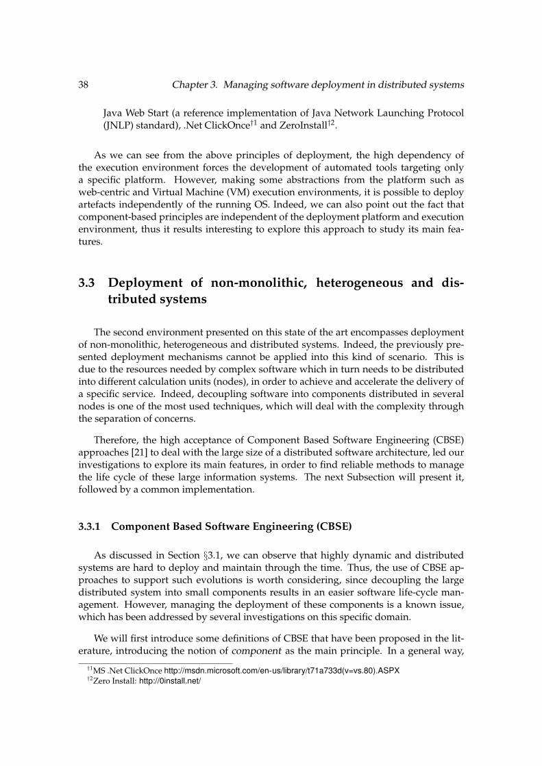
38 Chapter 3. Managing software deployment in distributed systems
Java Web Start (a reference implementation of Java Network Launching Protocol(JNLP) standard), .Net ClickOnce†1 and ZeroInstall†2.
As we can see from the above principles of deployment, the high dependency ofthe execution environment forces the development of automated tools targeting onlya specific platform. However, making some abstractions from the platform such asweb-centric and Virtual Machine (VM) execution environments, it is possible to deployartefacts independently of the running OS. Indeed, we can also point out the fact thatcomponent-based principles are independent of the deployment platform and executionenvironment, thus it results interesting to explore this approach to study its main fea-tures.
3.3 Deployment of non-monolithic, heterogeneous and dis-tributed systems
The second environment presented on this state of the art encompasses deploymentof non-monolithic, heterogeneous and distributed systems. Indeed, the previously pre-sented deployment mechanisms cannot be applied into this kind of scenario. This isdue to the resources needed by complex software which in turn needs to be distributedinto different calculation units (nodes), in order to achieve and accelerate the delivery ofa specific service. Indeed, decoupling software into components distributed in severalnodes is one of the most used techniques, which will deal with the complexity throughthe separation of concerns.
Therefore, the high acceptance of Component Based Software Engineering (CBSE)approaches [21] to deal with the large size of a distributed software architecture, led ourinvestigations to explore its main features, in order to find reliable methods to managethe life cycle of these large information systems. The next Subsection will present it,followed by a common implementation.
3.3.1 Component Based Software Engineering (CBSE)
As discussed in Section §3.1, we can observe that highly dynamic and distributedsystems are hard to deploy and maintain through the time. Thus, the use of CBSE ap-proaches to support such evolutions is worth considering, since decoupling the largedistributed system into small components results in an easier software life-cycle man-agement. However, managing the deployment of these components is a known issue,which has been addressed by several investigations on this specific domain.
We will first introduce some definitions of CBSE that have been proposed in the lit-erature, introducing the notion of component as the main principle. In a general way,
†1MS .Net ClickOnce http://msdn.microsoft.com/en-us/library/t71a733d(v=vs.80).ASPX†2Zero Install: http://0install.net/

3.3. Deployment of non-monolithic, heterogeneous and distributed systems 39
CBSE aims to leverage the main benefits of SE in terms of development, integration,maintenance, re-usability and separation of concerns, among others. However, a morespecific definition was proposed by Szyperski [96], being one of the most used:
” A software component is a unit of composition with contractually specifiedinterfaces and explicit context dependencies only. A software component can bedeployed independently and is subject to composition by third parties. ”
In another definition, Heineman et al. [58] define a component as:
” A component model defines a set of standards for component implementa-tion, naming interoperability, customization, composition, evolution and de-ployment. ”
We can note that this definition puts more emphasis in the development model, whichnot only leverages the abstract system composition, but also covers the global systemdeployment from the underlying pieces.
The main characteristics of a component, shown in §3.1 can be summarized as fol-lows:
• Interfaces specification. The available functionalities of a component.
• Explicit dependencies. A component could require other component’s function-alities or native libraries to work correctly. If so, such requirements should be ex-posed.
• Instantiation. Multiple instances of the given type can exist.
• Deployment independence. A deploy unit represent the whole component, whichcan be reused. However, this feature can be discussed.
Moreover, a component-based approach can define an Architecture Description Lan-guage (ADL). This is useful to describe the structure of a software, in a formal way [100][70] [75]. ADLs are declarative languages that describe a system’s architecture as a set ofcomponents, connectors, bindings and configurations. Such a language can be used toassemble components, based in two elements:
• Instances. They are the main elements which actually embody the required appli-cation’s functionalities, constituting the business logic.
• Connectors. A link between component’s instances, determined by the exposedprovided and required functionalities of the used types.
In an ADL, the specified interfaces can be bound between component instancesthrough connectors, which are identified as ”required” and ”provided” interfaces. The

40 Chapter 3. Managing software deployment in distributed systems
ComponentInstance
Communication
Interface
Figure 3.1: Components and their main characteristics.
complexity management can be achieved using a descriptive hierarchical composition,allowing scalability. For instance, Fractal [13] provides a structural description of soft-ware architecture. However, the needs can differ between systems, in order to associatefunctional, behavioural and system properties with the architecture.
In the case of big architectures, their division into small pieces can be very useful froma development and maintenance point of view, leveraging the component decouplingand the use of bindings between components to provide services. Indeed, an ADL canease the task of composing this layer, giving a complete management of the component’slife cycle, from the deployment to the instantiation. Moreover, we can associate to thedefined characteristics of components and its composition to an execution environment,which is in charge of the exploitation. However, the component’s implementation isnot defined at this level. The next Subsection will describe some of the most commonresources used to develop and deploy component-based applications.
3.3.1.1 Resources for CBSE artefacts deployment
The deployment facilities already introduced in section §3.2 are intended for deploy-ing traditional applications. Indeed, the necessary deployment information is managedby these deployment systems, such as dependencies, geographical distribution on tar-get sites, availability of required resources on these sites etc. Thus, programming ofcomponent-based software follows modular design principles, providing a broader viewof the system. Afterwards, the objective is to predict the deployment state during de-velopment, which is facilitated using component-based programming. Moreover, themodels present in component execution platforms provide explicit means to describecomponents and their dependencies. One typical example of a component based exe-cution platform is presented in this section, in which a modular development is used inorder to fit the execution environment that host the components.

3.3. Deployment of non-monolithic, heterogeneous and distributed systems 41
OSGi (Open Service Gateway initiative)
It was originally created to provide a general component model for Java platforms,running on top of domotic residential gateways. This model aims to implement a dy-namic module deployment based in Bundles. Moreover, the OSGi specification defines alife-cycle manager of these bundles, which are a set of encapsulated components. A Bun-dle designates a specific package from a JAR, which is mandatory for the deployment.Also, dependency contracts can be declared using manifest files, leveraging the notionof Java packages pointing to other bundles or parts of them. An Activator class repre-sents the internal code of a component, which defines the life-cycle of the Java moduleincluding code to start and stop the application. Moreover, the OSGi framework definesthe Java modules that can be deployed at runtime whose granularity dependency is rep-resented using either the JAR or the Java package of the Activator class. This frameworkalso defines the notion of internal service, using a central services registry as shownin figure §3.2, allowing dynamic inscription of new services. Thus, OSGi componentcontracts are dependency oriented. Two main implementations of this framework areApache Felix†3 and Eclipse Equinox†4, being the first used in several Enterprise ServiceBus and the latter the architecture of the Eclipse development environment.
A project called OpenTheBox†5 is the result of a OSGi platform implementation ded-icated to domotics. It is based on the OSGi platform Knopflerfish†6. Indeed, the core ofthis project relies in a central manager called Apam [22] running in a home automationbox, which provides an isolated collaboration environment between applications [36]and controls the conflicting accesses to the shared devices [37].
The specification allows interactions anticipated by the services architecture, but theymust be managed manually by the developer. This task is very complex and requires adeep knowledge of the OSGi mechanisms in order to finely handle all the possible casesto avoid errors.
Since our goal in this state of the art is to discuss the management of a large set ofsoftware services using components bound to each other, runtime control on the de-ployment of new components is mandatory. Thus, managing software deployment inhighly distributed environments, should be defined, highlighting the current challengesfor non-monolithic, heterogeneous systems software deployment.
3.3.1.2 Towards highly distributed environments
Distributed systems cannot be managed as centralized systems or single desktop ma-chines, for instance as described in section §3.2. This is due to the very different appli-cation domain in which a distributed approach is needed. Indeed, while desktop ap-plications can be easily deployed through local package and update managers (either
†3http://felix.apache.org†4http://www.eclipse.org/equinox†5http://openthebox.org/†6http://www.knopflerfish.org/

42 Chapter 3. Managing software deployment in distributed systems
Bundle(JAR)
Component(Class)
Component(Class)
Bundle(JAR)
Component(Class)
Component(Class)
Services
Export
Import
Import
Export
Manifest Manifest
Figure 3.2: OSGi Architecture.
at application or OS levels), distributed applications cannot be deployed nor updatedusing the same methods. Let’s take the example of a set of desktop machines runninga typical OS, in which basic functionalities are the same, as well as provided services.When a new feature is released for such OS, a single binary including the new featureis deployed on all the machines running the OS, regardless of the underlying hardware.On the other hand, a distributed application cannot be spread among all nodes throughthe same binary, since each one can offer a different service, or can be in charge of onlya part of a bigger system, on which the nodes’ hardware capabilities are not enough torun such a big application. This is true for most of the distributed applications, since thegoal is to share the resources of several machines (servers) to provide more and betterservices. Thus, software complexity can be divided among several machines, deployingdifferent parts of the application in different nodes. A big challenge appears when it isnecessary to deploy new features or update the current ones in this distributed environ-ments, since it is not possible to manually add or update this features for each machine:first due to the quantity and often the physical location of the equipment and second tothe uninterrupted use of the application, which cannot be stopped. The need of a finemanagement of this software layer is then justified.
Another issue comes with the networking layer availability, which is mandatory fordistributed applications. Since communication is the main activity in a distributed en-vironment, network robustness is then crucial. However, it is complicated to estimatethe network usage for a given application. As an example, web applications are oftenexposed to this problem, since they offer their services to an undetermined number ofclients. It is known that as the client requests increase, the application is more susceptibleto crash, due to the complex network management of all client’s connections. Usuallythis problem is solved by deploying more servers in order to increase the number ofmaximum connections, increasing also the cost of the infrastructure.
The difficulties presented in this section must be taken into account while developinga solution charged of the distributed applications’ deployment. This solution requiressupport by some kind of automation tool that should cover as much of deployment ac-
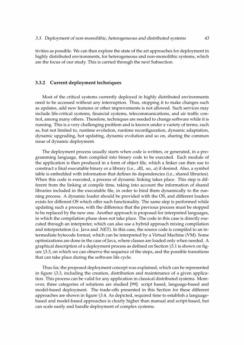
3.3. Deployment of non-monolithic, heterogeneous and distributed systems 43
tivities as possible. We can then explore the state of the art approaches for deployment inhighly distributed environments, for heterogeneous and non-monolithic systems, whichare the focus of our study. This is carried through the next Subsection.
3.3.2 Current deployment techniques
Most of the critical systems currently deployed in highly distributed environmentsneed to be accessed without any interruption. Thus, stopping it to make changes suchas updates, add new features or other improvements is not allowed. Such services mayinclude life-critical systems, financial systems, telecommunications, and air traffic con-trol, among many others. Therefore, techniques are needed to change software while it isrunning. This is a very challenging problem and is known under a variety of terms, suchas, but not limited to, runtime evolution, runtime reconfiguration, dynamic adaptation,dynamic upgrading, hot updating, dynamic evolution and so on, sharing the commonissue of dynamic deployment.
The deployment process usually starts when code is written, or generated, in a pro-gramming language, then compiled into binary code to be executed. Each module ofthe application is then produced in a form of object file, which a linker can then use toconstruct a final executable binary or a library (i.e., .dll, .so, .a) if desired. Also, a symboltable is embedded with information that defines its dependencies (i.e., shared libraries).When this code is executed, a process of dynamic linking takes place. This step is dif-ferent from the linking at compile time, taking into account the information of sharedlibraries included in the executable file, in order to bind them dynamically to the run-ning process. A dynamic loader should be provided with the OS, and different loadersexists for different OS which offer such functionality. The same step is performed whileupdating such a process, with the difference that the previous process must be stoppedto be replaced by the new one. Another approach is proposed for interpreted languages,in which the compilation phase does not take place. The code in this case is directly exe-cuted through an interpreter, which can also use a hybrid approach mixing compilationand interpretation (i.e. Java and .NET). In this case, the source code is compiled to an in-termediate bytecode format, which can be interpreted by a Virtual Machine (VM). Someoptimizations are done in the case of Java, where classes are loaded only when needed. Agraphical description of a deployment process as defined on Section §3.1 is shown on fig-ure §3.3, on which we can observe the sequence of the steps, and the possible transitionsthat can take place during the software life cycle.
Thus far, the proposed deployment concept was explained, which can be representedin figure §3.3, including the creation, distribution and maintenance of a given applica-tion. This process can be valid for any application in classical distributed systems. More-over, three categories of solutions are studied [99]: script based, language-based andmodel-based deployment. The trade-offs presented in this Section for these differentapproaches are shown in figure §3.4. As depicted, required time to establish a language-based and model-based approaches is clearly higher than manual and script-based, butcan scale easily and handle deployment of complex systems.
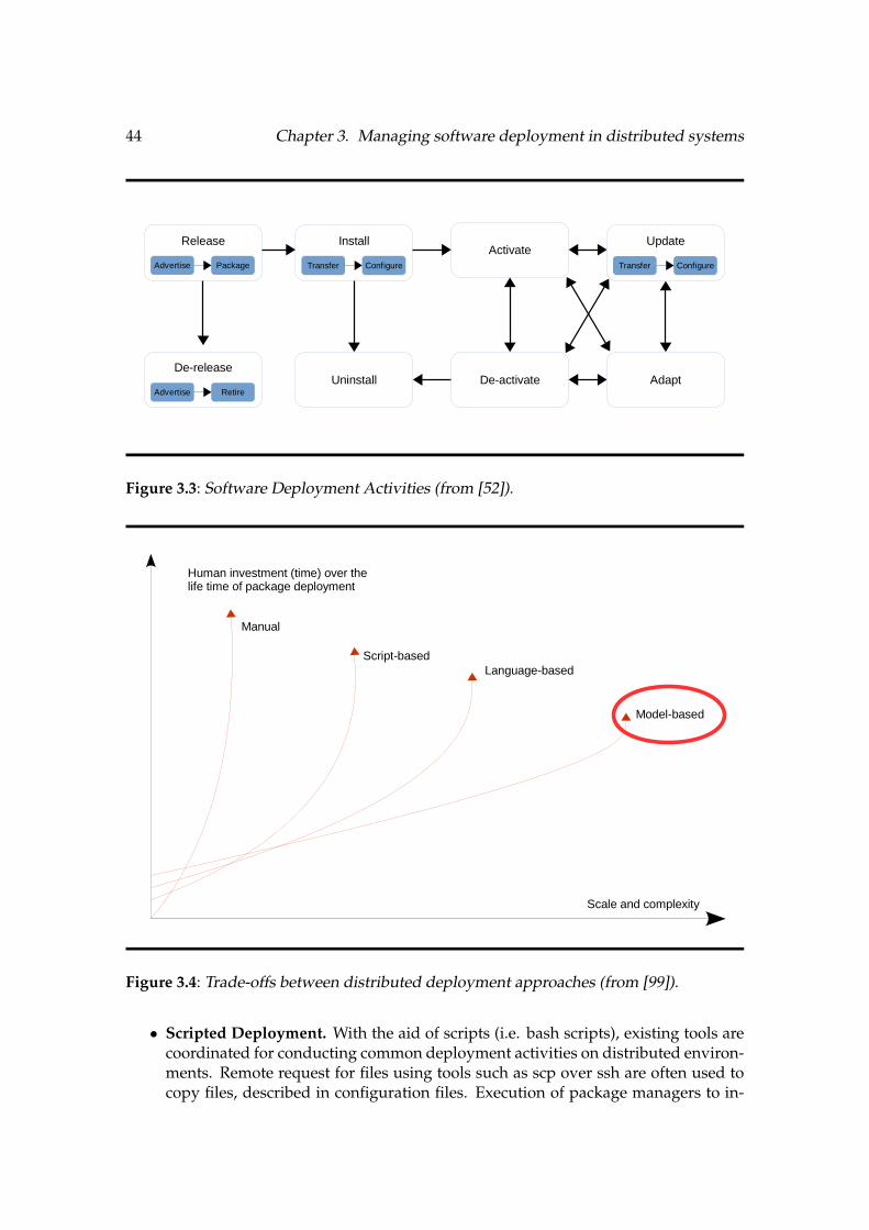
44 Chapter 3. Managing software deployment in distributed systems
Release
Advertise Package
Install
Transfer Configure
Update
Transfer Configure
De-release
Advertise Retire
Activate
Uninstall De-activate Adapt
Figure 3.3: Software Deployment Activities (from [52]).
Human investment (time) over thelife time of package deployment
Manual
Script-based
Language-based
Model-based
Scale and complexity
Figure 3.4: Trade-offs between distributed deployment approaches (from [99]).
• Scripted Deployment. With the aid of scripts (i.e. bash scripts), existing tools arecoordinated for conducting common deployment activities on distributed environ-ments. Remote request for files using tools such as scp over ssh are often used tocopy files, described in configuration files. Execution of package managers to in-
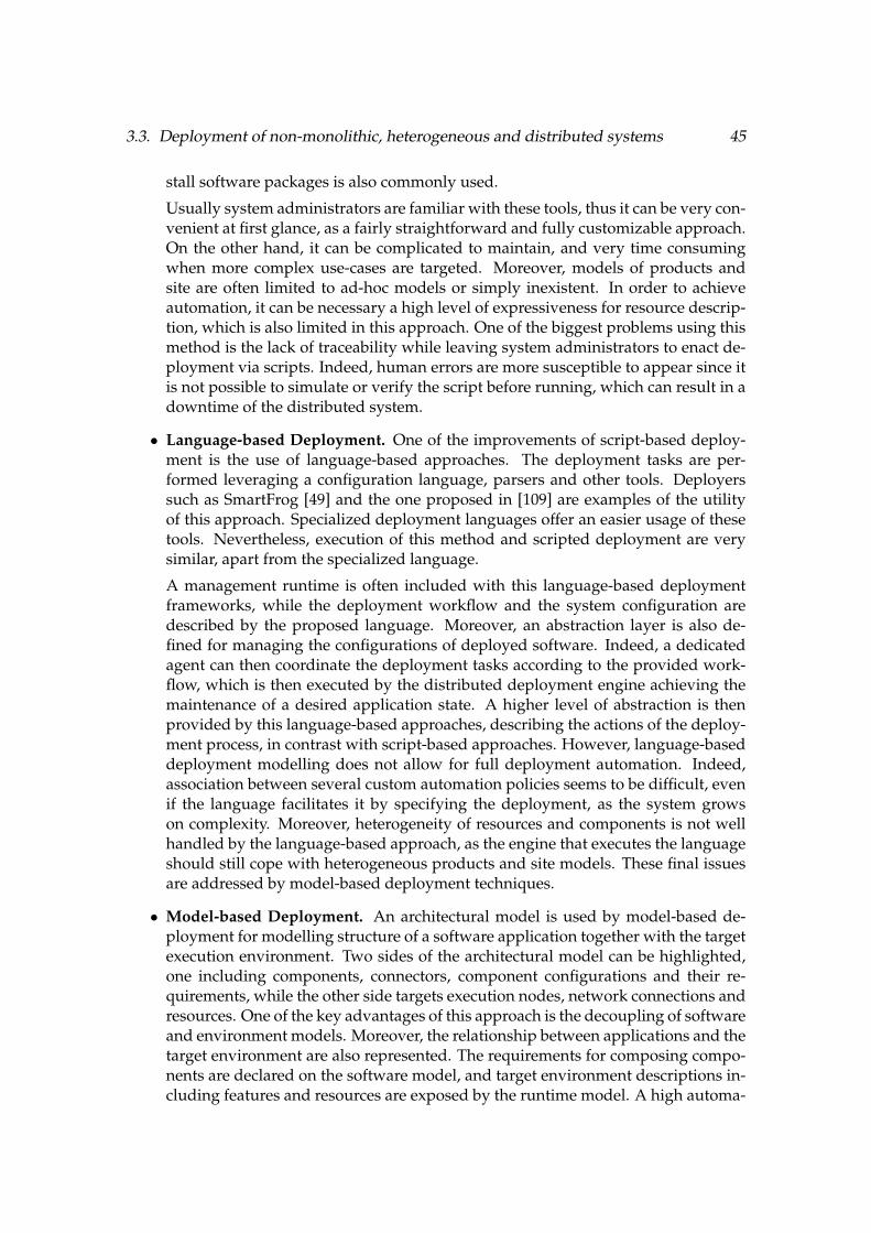
3.3. Deployment of non-monolithic, heterogeneous and distributed systems 45
stall software packages is also commonly used.
Usually system administrators are familiar with these tools, thus it can be very con-venient at first glance, as a fairly straightforward and fully customizable approach.On the other hand, it can be complicated to maintain, and very time consumingwhen more complex use-cases are targeted. Moreover, models of products andsite are often limited to ad-hoc models or simply inexistent. In order to achieveautomation, it can be necessary a high level of expressiveness for resource descrip-tion, which is also limited in this approach. One of the biggest problems using thismethod is the lack of traceability while leaving system administrators to enact de-ployment via scripts. Indeed, human errors are more susceptible to appear since itis not possible to simulate or verify the script before running, which can result in adowntime of the distributed system.
• Language-based Deployment. One of the improvements of script-based deploy-ment is the use of language-based approaches. The deployment tasks are per-formed leveraging a configuration language, parsers and other tools. Deployerssuch as SmartFrog [49] and the one proposed in [109] are examples of the utilityof this approach. Specialized deployment languages offer an easier usage of thesetools. Nevertheless, execution of this method and scripted deployment are verysimilar, apart from the specialized language.
A management runtime is often included with this language-based deploymentframeworks, while the deployment workflow and the system configuration aredescribed by the proposed language. Moreover, an abstraction layer is also de-fined for managing the configurations of deployed software. Indeed, a dedicatedagent can then coordinate the deployment tasks according to the provided work-flow, which is then executed by the distributed deployment engine achieving themaintenance of a desired application state. A higher level of abstraction is thenprovided by this language-based approaches, describing the actions of the deploy-ment process, in contrast with script-based approaches. However, language-baseddeployment modelling does not allow for full deployment automation. Indeed,association between several custom automation policies seems to be difficult, evenif the language facilitates it by specifying the deployment, as the system growson complexity. Moreover, heterogeneity of resources and components is not wellhandled by the language-based approach, as the engine that executes the languageshould still cope with heterogeneous products and site models. These final issuesare addressed by model-based deployment techniques.
• Model-based Deployment. An architectural model is used by model-based de-ployment for modelling structure of a software application together with the targetexecution environment. Two sides of the architectural model can be highlighted,one including components, connectors, component configurations and their re-quirements, while the other side targets execution nodes, network connections andresources. One of the key advantages of this approach is the decoupling of softwareand environment models. Moreover, the relationship between applications and thetarget environment are also represented. The requirements for composing compo-nents are declared on the software model, and target environment descriptions in-cluding features and resources are exposed by the runtime model. A high automa-
46 Chapter 3. Managing software deployment in distributed systems
tion level of the process is achieved by using these models, while the re-usabilityis improved. When the software is deployed in different execution environments,the re-usability of the model is of importance. In the same way, the model of theexecution environment may be reused for deployment of many different applica-tions. Based on the architectural model created during the development phase,component-based systems are helpful to define the software deployment model.Thus, model-based approaches and component-based approaches are especiallysuitable to conceive an automated tool for distributed software deployment.
3.3.3 Docker
Following the idea of automated deployment, Docker, a client-server engine whichprovides deployment of applications in form of containers, has recently caught the at-tention of the software engineering community. Indeed, it allows rapid deployment ofcontainers which provides a complete environment isolated from the host machine, onwhich a preloaded application can run from a pre-packaged image. This allows to dis-tribute software packages using any of the methods cited previously (scripted, languageor model based), since it is possible to organize the self-contained packages and deploythem as needed.
Docker is intended to provide the following services [104]:
An easy and lightweight way to model reality. It’s minimalistic copy-on-write modelallows to create and modify Docker applications very quickly. Indeed, the applica-tion built on top of Docker will use only the strictly necessary dependencies to run,and since no hypervisor is running, the use of resources is improved.
A logical segregation of duties. Operations and Developers are now separated, sincethe code will run in a specific container, which was specifically designed to run aspecific application.
Fast, efficient development life cycle. Code maintenance is simpler, since portability isone of the main advantages of Docker.
Encourages service orientated architectures. Docker also encourages service-orientedand microservices architectures. Docker recommends that each container run a sin-gle application or process. This promotes a distributed application model where anapplication or service is represented by a series of interconnected containers. Thismakes it easy to distribute, scale, debug and provides introspection for the appli-cations.
After a review of different deployment methods from manual to model-based usingcomponents or containers, we can highlight that, even if the initial cost as well as in timeas in resources can be very high, the use of model-based approaches provides betterhandling of a distributed system. Thus, exploration of these methods is of high interestin our study. The next sections aim to provide a good understanding of these model-based approaches.

3.3. Deployment of non-monolithic, heterogeneous and distributed systems 47
3.3.4 M@R in Dynamic Adaptive Systems (DAS)
With a view to ease software development and deployment for very large and com-plex information systems, Model Driven Engineering (MDE) focus on, at first, givingsimple, abstract and different points of view of information systems, without modifyingthe actual system. In a second place, a branch of MDE, called Model Driven Architec-ture (MDA) [65] aims to provide, through Domain Specific Languages (DSLs) coupledwith code generators, software development tools and methods. This approach is ableto generate executable code from the abstract model, that can be generated for differenthardware architectures.
Indeed, information systems have become, in only two decades, an indispensabletool for multiple human organisations. The gravity on the economic and social impactswhen a dysfunction or stop occurs make them evolve into ”eternal systems”, virtuallypermanently available, which on practice can be translated into a per year availabil-ity rate of 99,9% [105]. Strongly correlated with the usability evolution, and the veryshort duration of the functionalities, these constraints impose to let these systems opento non-predictable evolutions, from the time of the first design. For instance, it is nowvery complicated to anticipate the next services to be offered by an airport to its users.It is even more difficult to design the connectors or interfaces which will allow futuremodules to be connected and leverage the airport data in order to provide such a newservice. However, in 5 years this system should integrate it for the needs of a non-stopmarket without any interruption or alteration of the running services.
We can then consider these critical systems as Dynamic Adaptive Systems (DAS)[74], [79]. Continuous update mechanisms are then carried into the target platforms,in order to change at runtime the software already deployed. Taking into account thisdynamic behaviour, DAS are defined using a paradigm based on components, on whichthe management of these components’ deployment is considered as an evolution of theapproach.
DAS were typically deployed on critical platforms such as airports or banks, whichhad no tolerance to downtimes. However, in the last years the pervasiveness of softwarein all domains demand a downtime rate near to zero, including phones, domestic Inter-net gateways and domotic services [82]. These requirements need to be supported bycontinuous updates, even for this non-critical systems.
The development model was also changed drastically, in order to follow the softwareplasticity present in these systems. When V cycle was widely used and preferred overother development methods in the 80’s, coming from the design and initial specificationto the code generation or implementation, nowadays Agile methods [95], which aimto bring in shorter development cycles, are more recommended and used, in order torespond more quickly to specification evolutions thanks to users’ feedback. Combinedto this, the new approach of Continuous Integration (CI) introduces a new test systemable to be updated with new artefacts of continuous development. By adopting sucha methodology, non-critical systems and DAS specified constraints are brought moreclosely, converging in the idea of moving together abstractions of these two domains.

48 Chapter 3. Managing software deployment in distributed systems
Therefore, the V approach from the 80’s is becoming obsolete, while agile methodstend to expand it at every development cycle. It is then possible to develop and deploysoftware for critical and non-critical systems in a continuous manner. MDE approachesto generate code, and especially the MDA unidirectional approach which uses a modelto produce code, must take into account the inherent bidirectional development modelof this continuous cycle. Moreover, code generators must provide reverse operations toallow cyclic code, which can be present at design time. This can be useful to deal withlegacy code as much as at design time, which is one of the main concerns of MDE, as inthe tooling, beyond an approach of design-to-code.
model@runtime
node0
Radio
MCU
Peripherals
node1
Radio
MCU
Peripherals
node2
Radio
MCU
Peripherals
Model layer
Running systemlayer
Reconfiguration
Synchronization
Figure 3.5: Model@runtime principle .
As a response to the problem of cyclic design stated previously, a paradigm calledModels@Runtime (M@R) appeared, aiming to combine MDE techniques with tangiblesystems. As MDE, M@R were useful at first as a thoughtful visualization of a system,for simulation purposes [85], [10], [114]. A permanent updated model is then used torepresent abstractly a DAS at runtime. Every different element composing this model canbe represented in a schema, providing an easy navigation and an introspective analysis

3.3. Deployment of non-monolithic, heterogeneous and distributed systems 49
through the model layer. Reasoning about the state of the system is also possible usingthe same layer.
Leveraging not only the introspection capability of the model, but also the intersec-tion between computational reflection and models, Brice Morin [77] worked with thisModel@Runtime layer aiming to modify it, through the reflexive model representation.Using this intersection allows to modify the internal state of a system [86]. Morin’s M@Rapproach aim to build systems with reflexive capacities, having also intersection andintrospection features present in the same layer. As an abstract layer, the proposed re-flexivity can be asynchronous, allowing modifications before affecting the real system,i.e. for testing purposes. The principle of model@runtime is illustrated on figure §3.5.
These asynchronous properties separate strongly the actual system and the model,giving to MDE techniques the possibility to manipulate the reflexive layer without af-fecting at all the running platform. Moreover, a schematic representation leveraging thereflexive layer can be extracted from the actual system, in order to modify it. This mod-ification can be in the form of component’s adding or removal in the extracted model,then thanks to a version comparison between both the actual and the modified model,it is possible to actually trigger updates on the platform. A bidirectional connexion alsoexists, since any modification to the external platform will be reflected in the M@R layer.Modifications in the model can be manipulated before the deployment allowing verifi-cations, in addition to a more flexible way to test different configurations. For instance, ifwe want to deploy components with dependencies, the platform itself will avoid the de-ployment if any of the dependencies are not met. At the model level, the same changescan be executed regardless of the order, if the adaptation execution is done after theadding/removal of the components, on which the model is less constrained than theplatform. While the restrictions of the platform avoid the direct use of MDE approachesto manage the adaptations, the model can be manipulated to delay these restrictionsin the application of the reflexive model, allowing MDE approaches to manipulate themodel without following any order.
Approaches such as feature models or aspects [79] coupled with composition algo-rithms, can take advantage of the asynchronous capabilities of M@R in order to composea model from the DAS architecture. Since all operations can be done offline, no con-straints are imposed by the tangible platform before the deployment, while the systemcan decide when to synchronize. Conceiving and composing models is then essential toassemble a whole DAS. Indeed, several paradigms of composition are also needed, basedon previous works [78], [66], [89], that encourage the use of software components to en-capsulate the life cycle and composition operators. Moreover, these paradigms are alsoneeded to explore the exploitation viability at this granularity level, in order to managethe different parts of DAS application layer. In the next Section, we will explore a con-crete approach of the M@R paradigm, called Kevoree, which aims to provide a completedevelopment and deployment framework for DAS.

50 Chapter 3. Managing software deployment in distributed systems
3.3.5 Kevoree as a flexible models@runtime approach
Kevoree is a component-based development framework for applications running onDAS, based on the paradigm of Models@Runtime. This approach proposes an abstractmodel through which it is possible to manipulate the different concepts that characterizesa distributed system. It provides the following concepts to design a distributed systemfeaturing dynamic adaptations:
• The Node concept is used to model the infrastructure topology.
• The Group concept is used to model the semantics of inter-node communication,particularly when synchronizing the reflection model among nodes.
• A Channel concept is included in Kevoree to allow for different communicationsemantics between remote Components deployed on heterogeneous nodes.
All Kevoree concepts (Component, Channel, Node, Group) obey the object type designpattern [112] in order to separate deployment artefacts from running artefacts
Kevoree aims to provide an abstraction able to manipulate the main concepts of a dis-tributed system, in order to ease the adaptations management for this system. To do that,Kevoree proposes several features: synchronization and de-synchronization between thereflexive model and the actual system at runtime, separation of concerns between thebusiness logic and its interactions and finally the dissemination of reconfigurations andresource heterogeneity on which the system is being executed.
Separation of concerns. A distributed application is composed of specific business logicbut also communication means (code). Unlike business logic, communicationmeans does not have necessarily specific code due to the application. Thus, it isinteresting to separate these two entities, which allows to reuse the different soft-ware blocks. This simplifies the component’s business logic development, sincethe communication concerns are separated. Moreover, the adaptation of the com-munication means between components regarding the context is required for a dis-tributed application.
Distribution management. In order to distribute different functionalities to the differentnodes in a system, an abstract representation is provided, in which these character-istics are modelled and can be manipulated at runtime.
De-synchronization. A process of validation carried in the reflexive model before itsapplication is one of the main advantages of this feature. This de-synchronizationis possible thanks to the concept of models@runtime that is the base of Kevoree, inwhich an adaptation is defined through a model that can be validated. Coherenceof the configurations is then validated to be sure that no unstable behaviour canbe reached or a complete breakdown can happen. In a distributed context, this isof high importance, in order to avoid an adaptation that cannot be executed by allnodes.

3.4. Towards software deployment on the IoT 51
Adaptations dissemination. Once an adaptation is executed, every node must be noti-fied of this change, so it can be taken into account by the whole system. However,in a distributed system it is not possible to guarantee an uninterrupted commu-nication between nodes, since networks are subject to communication errors ordisconnections. These constraints are considered in the dissemination of the adap-tations, to provide a coherent evolution. Different synchronization methods arethen used regarding the communication means between nodes.
Execution platforms heterogeneity. Distributed systems are composed of several exe-cution platforms, such as mobile nodes (smart phones), PC, servers or embeddedsystems. It is then necessary to represent in the Kevoree model the differencesbetween platforms and their specific characteristics.
Kevoree supports multiple execution platforms (e.g., Java, Android, MiniCloud,FreeBSD, Arduino). For each target platform, it provides a specific runtime container.As a result, Kevoree offers an environment to facilitate the implementation of dynami-cally reconfigurable applications in the context of distributed systems based on differentexecution platforms.
Moreover, the principle of a model@runtime lies in the general knowledge of theentire system (the reflected model of the running system), which is present in everyparticipant. Indeed, the reflected model should be available in memory for its rapidmanipulation, thus we can imagine the big quantity of memory needed to represent largemodels featuring a vast quantity of nodes. In addition, each node can have instances ofone or more components and its parameters, which increase even more the size of themodel in memory.
Once we have discussed how software deployment on a highly distributed and het-erogeneous system can be managed, we need to discuss about the existing approachesto deploy software on very constrained environments which were already introduced inthe previous chapter. The IoT is a part of this very constrained systems, thus we willpresent in the next Section how software can be deployed onto these systems.
3.4 Towards software deployment on the IoT
Once a state of the art discussing the current approaches to provide dynamical be-haviour at the application level for highly distributed systems has been conducted, asummary of current deployment techniques used on constrained environments will bepresented. Indeed, several research works propose component models coupled withcode distribution approaches, in order to manage the software layer in a constrained en-vironment. However, these existing works are rather intended for WSN. While this rep-resents smaller networks without IP connectivity, WSNs are composed of devices typicalof the IoT, thus the applicability of these approaches on larger, IP enabled networks suchas the IoT is worth considering. We will then introduce two aspects of software deploy-ment on IoT systems: a static and a dynamic approach.

52 Chapter 3. Managing software deployment in distributed systems
3.4.1 Static deployment
This is a straightforward solution to deploy new features or bug fixes in embeddedsystems, an essential part of the IoT infrastructure presented in this thesis. It consists inchanging the entire kernel image for a new one, which must be either flashed physicallyor transmitted through the network, followed by a complete reboot of the system. In-deed, sharing a large kernel image can be very energy consuming for wireless batterypowered devices. Advantages of this technique are the possibility of deep changes intothe kernel or applications, as well as deployment of a complete different OS.
0
0
1 2 3 4
1 2 3 4 5 NPage
ObjectP
objS
pageS
5Packet
43
pktS
Figure 3.6: Deluge’s Data Management Hierarchy (from [60]) .
Through a full kernel replacement, Deluge [60], a very popular protocol using thisapproach, supports distribution and flashing of a binary image for constrained devices,through the TOSBoot bootloader. It was mainly developed for TinyOS [72] a WSN OS.Indeed, this protocol divides large objects into pages, which is the basic unit of transferand provides three advantages: (i) it limits the amount of states a receiver must maintainwhile receiving data, (ii) it enables efficient incremental upgrades from prior versionsand (iii) allows for spatial multiplexing. Moreover, each page is divided into smallerpackets of a fixed size, as we can observe on figure §3.6. Each packed is checked witha 16-bit Cyclic Redundancy Check, in order to ensure consistency. The protocol estab-lishes three operation modes: MAINTAIN, RX or TX. The MAINTAIN state providesthe information about the pages and version of them, while putting them available andready to be shared. Indeed, when a page is correctly received, it can be shared again toanother node requesting it, thus having the entire object is not necessary to share parts ofit. The RX state will be enabled when a node is requesting pages of an object. Moreover,it ensures the reception by choosing actively a trusted source, which can be changed ifit is not reachable anymore. Finally, during TX, a node is responsible to broadcast anyrequested packets for a given page until it finishes to send all packets. Then it comesback to the MAINTAIN state.
As stated previously, this technique incurs in a high energy overhead while distribut-ing the entire image through the network. Moreover, re-installation of a new firmwarerequires a system reboot, disrupting any running applications which can lead to data

3.4. Towards software deployment on the IoT 53
loss of those applications. In order to solve the first problem, some approaches [61], [88]supply a code image comparison in order to provide incremental updates, reducing thesize of the update. Indeed, the main drawback of such approach is the significant in-crease of CPU energy consumption, due to the complexity of the difference calculationmechanism.
We will then discuss, through the next Subsection, the current possibilities in IoTdevices to actually allow dynamic behaviour by deploying new software at runtime,while focusing on the decomposition of these software artefacts in smaller deploy unitsto cope with the main drawbacks of the static deployment.
3.4.2 Dynamic deployment
The process of software deployment can differ significantly from classical distributedsystems to IoT systems. This is due to the underlying hardware differences discussedthroughout this state of the art. While non-constrained nodes present in classical dis-tributed systems are able to run VMs to execute precompiled bytecode, written in highlevel languages such as Java, IoT devices are not able to run a complete JVM, but rathervery limited ones such as Mate [71] and Darjeeling [12]. Moreover, related research [84]found JVMs very resource consuming in small devices typical of IoT, since they add aconsiderable CPU overhead while running, which avoids a long-term use for batterypowered nodes. Thus, we will focus on software deployment for applications compiledas binary code, which can be executed directly by the native platform. Indeed, in theembedded systems domain, which embodies most of the devices used in IoT, bare metalapplications are the most common procedure to provide services or functionalities. Phys-ical flashing of the binary image is the usual deployment method, since it can be doneat the manufacturing step of the embedded system, without considering any furtherfirmware changes. With this limitation, it is even more complicated to distribute appli-cations among several nodes which are physically separated, since manual flashing ofevery node in a typical IoT system cannot be worth considering due to the huge numberof nodes. Thus, we need to study the current alternatives to deal with this problem.
Operating systems used in embedded systems and Wireless Sensor Networks (WSN)provide several methods to deploy new applications at runtime, such as:
i. Scripting languages [28] [68].
ii. Virtual Machines.
iii. Kernel replacement.
iv. Position Independent Code.
v. Relocatable code.
As we discussed in this section, research shows that only non-interpreted code is worthconsidering for long term applications. Thus, scripting languages and VM approaches
54 Chapter 3. Managing software deployment in distributed systems
will be discarded as a method to deploy new features, in the context of this thesis. More-over, kernel replacement has been discarded due to its very high energy consumptionwhile transmitting large kernel images.
As presented in this section, applications deployment for IoT systems differs in sev-eral ways from classical distributed systems. In order to cope with this differences, whichare mostly hardware and network related, approaches coming from the embedded sys-tems and WSN domains have been proposed. We will discuss the two last methodsalready introduced above, aiming to provide dynamic deployment:
• Position Independent Code (PIC). As mentioned previously in this chapter, the ex-ecutable code usually follows the process of dynamic relocation to find the neededsymbol’s addresses, then execute the code. PIC follow a different approach to runapplications. It consists in the use of relative jumps rather than absolute addressesto find symbols, mitigating the need of run-time relocation. Several overheads canbe introduced by the use of this technique, such as pre-loading of addresses beforemaking jumps, more needed jumps while calling kernel or another module, func-tions registration and de-registration and the necessity of a jump table. Further-more, a PIC compatible compiler should be used, in order to produce a loadablemodule using this method, which can be unavailable for certain CPU architectures.For instance, AVR microcontrollers supports this type of compilation, but it is lim-ited to a 4KB program size, while it is not known a compiler supporting PIC forMSP430 CPUs. Applications running non-PIC methods to deploy new moduleshave shown a 13% better performance compared to PIC [26]. However, the globalefficiency while running most of PIC modules is the same as if they were flasheddirectly on the device.
• Relocatable code. This technique is the one used by classical OSs such as Unixbased and Windows, also implemented for IoT devices [31]. It uses run-time dy-namic linking, relocation and loading of modules compiled using the standard Ex-ecutable and Linkable Format (ELF). This format includes the program code anddata, as well as detailed information about unresolved symbols. To resolve them,the OS must adjust properly the absolute addresses included in the file, depend-ing on the module’s location in memory. A relocation type also embedded in theELF file specifies how the data or code addresses should be updated. These typesdepend on the CPU architecture, for instance, an MSP430 CPU counts with onlyone type of relocation, while the AVR architecture has 19. Both architectures arewidely used for embedded systems and IoT devices. Once each unresolved sym-bol is updated with the new address, the .data and .bss sections of the ELF filecan be loaded into RAM, and the .text is copied to ROM, then the program canbe executed following specific OS functions. Overheads of this method include thetransmission over the network of a large ELF file depending on the 32 or 64 bitsarchitecture, a symbol table in which names are used to represent each unresolvedsymbol, also increasing the size of the ELF file, and finally a CPU overhead is in-curred while resolving symbols. As in the PIC method, no reboot is required to runthe new application or to apply an update.

3.4. Towards software deployment on the IoT 55
Mechanism
VM PIC Reloc. OS Protection Kernel Modif. Kernel Replacement Loose Coupling
Mate [71] • • •
TOSBoot [60] •
SOS [56] • • •
Contiki [32] • • •
RETOS [15] • • • •
Darjeeling [12] • • •
SenSpire [26] • • •
Enix [16] •
Table 3.1: Feature Comparison (adapted from [84]).
Other features of the proposed approaches can be considered, such as OS protection,low level kernel modification and even a whole kernel replacement. The loose couplingbetween new added modules and the underlying kernel is also important, since addedflexibility of development allows scalability and fast upgrade of components. Severaloperating systems using the discussed approaches are shown in table §3.1. VMs are in-cluded in this table since they offer high loose coupling and OS protection, and can besuitable for very short life-cycle applications running on IoT devices. Moreover, SOS,RETOS, SensSpire and Enix, are included as a matter of comparison, but the implemen-tation and design details are out of the scope of this state of the art.
Component based approaches
As for Component-based module dissemination and deployment, an effort to pro-vide component models for WSN were already done by the FiGaRo approach [80], im-plemented on top of the Contiki OS. It aims at providing both a component model formodules development and a distribution mechanism using a new dissemination proto-col. A very complex component model relying on the use of C macros handled at com-pile time is proposed for modules development, which are directly used by the devel-oper. Indeed, this programming model demands a deep knowledge of the set of featuressupported by the approach, increasing development complexity. Moreover, node’s up-dates and reconfigurations are determined by the programmer using a Domain SpecificLanguage (DSL). Dependencies in other components should be explicitly declared alsousing such DSL, which are not managed by the node itself. Thus, a dependency graph isbuilt by the node to find if a dependency is not met, but the approach does not explicitlyexplain if any action will be performed in case of a non-satisfied dependency. It ratherperforms a recursive graph parsing, until the needed dependency is met, otherwise itexcludes the new component or update. In order to achieve non-monolithic deploymentin an heterogeneous network, the approach provides a mechanism of rules that are de-clared using the same DSL, in order to filter the targeted nodes, instead of a fine selectionof the nodes to be updated. Moreover, even if the approach relies on the Contiki’s ELF

56 Chapter 3. Managing software deployment in distributed systems
loader, the extensive use of this DSL incurs in an overhead since system function callsare not done directly, but rather using the macros provided by the component model.
As for the component’s distribution mechanisms, a routing protocol is proposed tofind the best path to distribute a component. Thus, it relies in a mesh topology whichis built by piggybacking the current value of a node’s attributes on every outgoing mes-sage. Moreover, the proposed protocol makes use of complex message passing betweennodes in order to calculate the best path for the component’s chunks to be transmitted.Indeed, this can result in lots of redundant paths, although some efforts are made toreduce them. The presented protocol strongly depends on other application’s traffic toexploit enough messages in order to determine a representative topology of the mesh.Therefore, if there is no enough traffic, the protocol can ignore the whole network topol-ogy, resulting in an inaccurate components distribution.
The main found drawbacks can be summarized as follows:
• Complex component model relying on C macros, which must be well known bythe developer,
• Use of pre-defined rules to achieve fine selection of deployment targets,
• High CPU overhead caused by the use of non-direct function calls,
• Component distribution relies on complex routing dependent on network traffic.
After the analysis on the static and dynamic approaches, we can observe that theysucceed on the goal of deploying new software on very constrained nodes, althoughthey have several drawbacks. Indeed, most of them are related to the energy they needto succeed, and lacking of efficient ways to distribute and manage whole firmwares orparts of it. Moreover, the programming model of the proposed approaches can also bedifficult to learn, compared to traditional C programming. We need then to state whatare the main challenges while designing a new approach to cope with these drawbacks.
As presented on Section §3.3.4, the Models@Runtime approach can deal with mostof these drawbacks. Indeed, it proposes a way to model the network and the softwarelayer, without being dependent on the programming model and language used to de-velop components. Moreover, the network information is also modelled, thus there is nodependency on the topology to localize a specific node. Therefore, it is worth consider-ing to analyse if the existing M@R implementations can be adapted to provide a way tomanage and enact software deployment on IoT systems.
3.5 Conclusion
The focus of this work is to propose IoT solutions based on the three tools discussedon Section §3.1: runtime, management, and administration of the software layer on top ofthis constrained systems. More specifically, a management tool is proposed to deal with

3.5. Conclusion 57
the deployment issues typical of IoT systems, leveraging software engineering existingapproaches to solve very similar issues.
Indeed, decoupling IoT environments into software components and managing theirdeployment is not an easy task, since memory constraints, processing power, energyautonomy and network topology prevents the direct implementation of the same ap-proaches used in classical distributed systems, which is one of the motivations to con-duct this research.
Since there are no widely used IoT OS or execution environments for constraineddevices, it is very complicated to develop automatic deployment methods using the sameabstractions. Moreover, the use of high level execution environments such as VMs is notworth considering, due to the scarce resources found on these devices face to the highresourced needed by a VM.
In conclusion, even if deployment mechanisms for IoT devices exist and can be im-proved to reach a good reliability level and ease to use, manual firmware flashing forupdates and new features should not be worth considering, as it was explained in theprevious section. Moreover, figure §3.4 already shows that in classical distributed sys-tems manual deployment is not suitable for large-scale systems.
Given the available methods of deployment for new applications or feature updates,it is then necessary to evaluate which is the most advisable approach for its use and adap-tation in an automated deployment manager. Taking into account the already describedmodel-based techniques, the criterion to evaluate the previously presented approacheswill be based on the capability of such approach to be easily decoupled into components,that can be disseminated over the network using a minimum of transfers. Moreover, itis very important to have a good implementation of the local deployment procedures, aswell as the necessary tools to share deploy units to the entire network. We also highlightthe need of specific code distribution, since each node can perform a different task, thusneeds different software components to be deployed.
The presented CBSE and Models@Runtime concepts are essential to build our IoTsoftware architecture. Indeed, our research efforts were led to the design and imple-mentation of a software deployment manager dedicated to IoT systems, in order to en-able automatic deployment and dynamic adaptations. Thus, the introspection and thedynamic reconfiguration facilities offered by the models@runtime paradigm, and morespecifically the Kevoree approach, are an interesting source of inspiration. Indeed, theneed of a unified tool managing the software layer of an IoT environment comes withthe design of such IoT architecture. However, at this point the main differences regard-ing IoT systems and classical distributed system become more relevant, since the alreadyinvestigated approaches are intended for the latter.
Taking this state of the art as a source of inspiration, the purpose of this thesis is topropose a novel way to manage software deployment in IoT systems, facing at the sametime issues typical of distributed systems and the new ones raised by the constraints ofIoT devices.

58 Chapter 3. Managing software deployment in distributed systems
The next chapters are intended to explain the main contributions of this thesis, fo-cusing on the already discussed topics on this chapter, to finally propose an automateddeployment engine for IoT applications.
Part III
Contributions

Chapter 4
Models@Runtime for the IoT
Looking at our state of the art, various techniques have been proposed to enable soft-ware updates, which were presented in table §3.1. As for the full kernel replacementmechanism, which can be managed by an automatic tool [60], the excessive amount ofpower needed by this approach does not seem appropriated for a highly dynamic infras-tructure such as the IoT. The approaches making use of virtual machines were alreadyanalysed and it was found that they are not suitable for long-living applications [84].Even if some component models [80], [98] were proposed to provide an abstraction layerfor the life-cycle maintenance, it results in a very complex programming model and rout-ing protocols to distribute components, in addition to a finely tuned memory managerfor specific platforms and hardware architectures, which reduces scalability. Thus, thelack of a deployment manager which provides kernel modularization using relocationmechanisms, which seems the best way to provide new features and updates, motivatesour research to find an automatic and scalable approach to provide such a manager.
In this chapter, we describe the main challenges while designing a new middlewarededicated to IoT devices, in order to enable the management of software deployment andthe dynamic reconfiguration of IoT systems. Indeed, our middleware is inspired from theComponent Based Systems and the model@runtime paradigm which have been alreadydescribed in the previous chapter.
4.1 IoT specific requirements for model@runtime
As mentioned in the previous chapter, the model@runtime approach has been pro-posed and designed for distributed systems where nodes are powerful computers inter-connected through a very high-speed network. Some inherent characteristics of this ap-proach were thus designed without taking into consideration the very specific and con-strained nature of IoT systems. In this section, we present the specific characteristics ofIoT systems which make them incompatible with the current design of Model@Runtime,and we elicit a set of requirements to design a model@runtime approach for IoT systems.

62 Chapter 4. Models@Runtime for the IoT
Compared to a classical distributed system, an IoT system mainly differs through thethree following characteristics:
• an energy constraint: most nodes included in an IoT system are battery poweredwith limited capacity. This particular way of powering the computing nodes has adirect impact on the development of software. Indeed, if the software running onthose systems have not been designed with the energy constraint in mind, it willdrastically reduce the life time of the system.
• a very limited computing and memory resource: most nodes included in an IoTsystem presents a very limited amount of computing and memory resources com-pared to a more classical computing node. These resource constraints have an im-pact on software development since classical algorithm and design may not fit intosuch constraints.
• a multi-hop routing infrastructure: in an IoT system, most nodes are intercon-nected through a multi-hop routing infrastructure. This specific way of routingpackets through other nodes in the network directly impact the way of designinginter nodes communication since fulfilling any specific network communicationmay drain energy and computational resources from several nodes in the network.
Therefore, designing a specific model@runtime approach for IoT system will requireto cope with these three main characteristics which differs from classical distributed sys-tems. Typically, a model@runtime approach for distributed system is designed with twomain components:
• a model: which represents the current state of the whole distributed system. Thismodel typically represents three layers: (i) the hardware level with all nodes in-cluded in the system; (ii) the network level with all communication path betweenthe nodes, and (iii) the software level with all software components, their configu-rations and their communications paths. This model is used as the corner stone ofthe approach to deploy and perform dynamic evolution of the software system.
• a software agent: running on all nodes. This software agent is in charge of all activ-ities to transform this declarative model into a running system. These activities in-clude model interpretation (loading, comparison, and so on), software componentdownloading, and dynamic software loading. All software agents in the system areindependent and performs independently the specific tasks needed on each node.
In an IoT system, the software agent has to be redesigned and implemented in adifferent way to take more carefully into account the three inherent characteristics de-scribed above. The model has to remain the same conceptually, in order to interoperatewith hybrid systems which includes IoT nodes together with computing nodes with lesslimitation of computing power. We divided the problem of designing a model@runtimeapproach for IoT into the following two main challenges:

4.2. Kevoree for the IoT 63
• the intra-node challenge. This challenge is related to designing the software agentpart together with a typical IoT node in order to fit all activities related to localmodel interpretation and dynamic software loading into the resource constraintsIoT node. This challenge also relates to the evaluation and minimization of theperformance and energy overhead of the model@runtime approach.
• the inter-node challenge. This challenge is related to the design of new commu-nication schemes to take into account the underlying routing topology, in orderto minimize the energy consumption of the required model@runtime communica-tion. This includes in particular a communication scheme to minimize the energyconsumption related to software component downloading and distribution.
4.2 Kevoree for the IoT
Focusing on our first challenge, the intra-node case, we aim to develop a softwareagent able to provide a set of tools to leverage the models@runtime advantages andproperties, in order to provide an automatic platform for IoT software deployment andmaintenance. This section will present the design of such an agent, taking into accountthe previously mentioned characteristics.
One of the models@runtime approach implementations already discussed was theKevoree framework. As presented in section §3.3.5, the base of this framework is theKevoree meta-model, which was designed to follow a distributed architecture and alsooffers a minimalistic component model. Indeed, the implementation and design ofKevoree did not take into account any restriction on the underlying system, thus relyingon high memory and storage capabilities with fast processing features. Thus, we cannotenvision the direct mapping of this implementation on very constrained nodes such asIoT nodes.
However, some of the Kevoree activities are interesting for their use on a distributedenvironment such as the IoT. Indeed, Kevoree is able to perform reconfiguration anddeployment tasks, which are the main functionalities we are searching for. To be precise,we are interested on the following features:
• The meta-model to represent the whole distributed system. The representationproposed by Kevoree through the meta-model is very close to our IoT environment,since it focuses on independent nodes and provides abstractions for the communi-cation means, which is the main activity of an IoT node.
• Principles for model manipulation. Several tools are needed while changes onthe system are reflected on the model. It is then needed to change parameters, addor remove components, check for changes between old and new models and soon. Thus, tools like model serializer/deserializer, model comparing, and modelvisitors, are essential for a functional Kevoree implementation.
• Kevoree editor A web editor is available for model checking/editing. This is veryuseful while triggering adaptations by hand.

64 Chapter 4. Models@Runtime for the IoT
ComponentInstance
ComponentInstance
ComponentInstance
ComponentInstance
Channel/
Binding
ComponentInstance
model@runtimeIoT Physical Network
Internet / Cloud
Software componentsRepository
node0
Radio
MCU
Peripherals
node1
Radio
MCU
Peripherals
node2
Radio
MCU
Peripherals
node0 node1
node2
Figure 4.1: A M@R representation for IoT devices.
Our goal is then to provide a middleware that will be present on each node of the IoT sys-tem, and will take care of the various tasks imposed by the model@runtime paradigm.In figure §4.1, we can see a representation in which three IoT nodes are part of a smallnetwork. This example shows how the model is present on the three nodes, each nodehaving the knowledge about three available components on the repository, the instancespresent in the other two nodes and a binding through a channel between two compo-nents of different nodes. Moreover, any change of this configuration should be reflectedon the model, followed by the dissemination of these changes to the other nodes, andvice-versa, any change on the model will affect the actual node. Figure §4.3 describes theactions taken when a reconfiguration or adaptation is triggered.
Thus, we need to use only the previously described mechanisms provided by this ap-proach, and adapt the selected features to address the node’s hardware constraints. Thenext Subsection will take into consideration the minimal requirements towards the de-sign of a new M@R implementation for IoT nodes, inspired from the Kevoree approach.

4.2. Kevoree for the IoT 65
4.2.1 Minimal Kevoree properties needed on the IoT
As already discussed in section §3.3.5, the Kevoree meta-model can be easily trans-formed into Java code using a modelling framework. However, in our case this approachcannot be used. This is due to two reasons: first, we cannot use high-level languages suchas Java and second, we are limited to the C language which can be compiled for the IoTnode’s architecture already presented in §2.3.1. Moreover, meta-models follow very of-ten an object-oriented approach, which is not defined for procedural languages such asC. Thus, a direct transformation taking into account these constraints is not worth con-sidering. However, a similar approach for code generation and modelling tools can beproposed to meet the requirements of a model@runtime approach. Indeed, the KevoreeModelling Framework [46] can be adapted to support the generation of C code, in or-der to provide a fully Kevoree-like middleware for IoT devices. Even so, the efforts toadapt such a framework raise more and different challenges which are out of the scopefor this thesis. Since our goal is, first of all, to investigate the limits of an IoT node interms of memory, a manual implementation (transformation) of the meta-model and itsmodelling tools is then needed, by adapting the concepts to the limited resources ofthe node. Indeed, this allows a rapid prototype which can be finely tuned to meet thememory constraints present in IoT devices, in contrast to a more generic code generationapproach.
On the typical implementation of Kevoree, a core application is embedded in everynode. This application provides to each system element (node, component, communica-tion channel, groups) an access to the current model, allowing to submit new configura-tions through new models. If this Kevoree Core receives a new model, it is in charge ofthe following actions:
• Model validation. Verify if the serialized model actually corresponds to a validKevoree model, by parsing it and proceeding to deserialization.
• Adaptation planning. Once the model is deserialized and loaded in memory amodel comparison is performed. A list of differences is then generated, describ-ing the actual adaptations to be performed, which may contain adding/removingcomponents and modifications to parameters (reconfiguration).
• Adaptations execution. Following the adaptation plan, the adaptations (compo-nent deployment, reconfiguration) will take place, in the following order:
i. Stop Instance. A running instance will be stopped.ii. Remove Binding. If a binding between 2 channels of a component exists, it
will be removed.iii. Remove Instance. A component instance will be removed.iv. Remove Deploy Unit. A deploy unit will be removed.v. Update Binding. When a binding between channels exists, it will be changed
to the new channels.vi. Update Deploy Unit. An existing deploy unit gets replaced by a new one
(most recent version).

66 Chapter 4. Models@Runtime for the IoT
Figure 4.2: State-transition diagram showing the adaptation process in a typical Kevoreeimplementation.
vii. Add Deploy Unit. If a new deploy unit is needed, it will be downloaded andmade it available for instantiation.
viii. Add Instance. An instance will be created from an existing Deploy Unit.
ix. Add Binding. A new binding between two channels will be created.
x. Update Dictionary Instance. If a dictionary entry exists for an instance, it willbe updated with a new value.
xi. Update Instance. An existing instance will be updated with a new version.
xii. Start Instance. An existing instance which was stopped will be started.
This order will avoid any inconsistency while performing the adaptations.
The model validation is delegated to any system element registered as a listener.Each component, communication channel or node can make use of an interface and beregistered on the core in charge of the model management. Once registered, the instanceis notified with regard to the different reconfiguration stages. Figure §4.2 representsin a state-transition diagram the integration of listeners with the process of a typicalimplementation of Kevoree.
In contrast, our design for IoT devices cannot follow the same algorithm. Indeed, themodel checking and rollback mechanisms require to save the entire model in memoryfor checking and, if something goes wrong, to bring back the previous model. This isvery memory consuming for our application, thus a typical IoT device would not be able
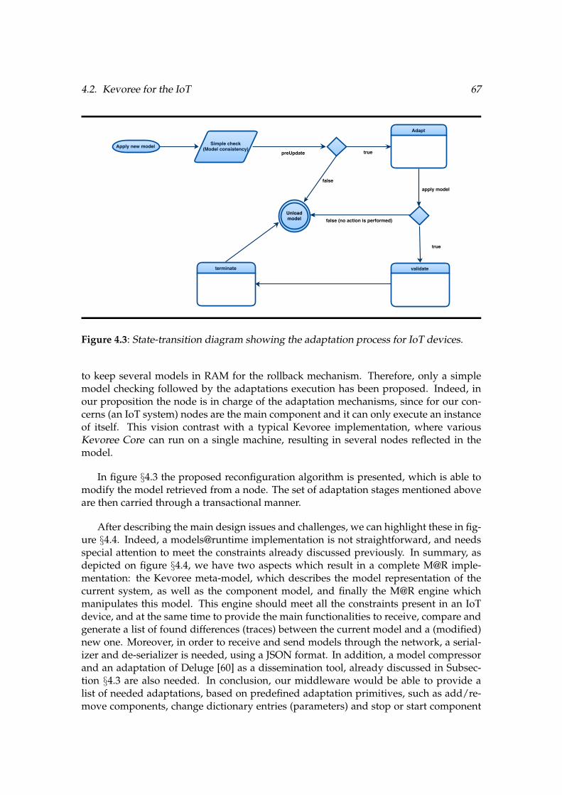
4.2. Kevoree for the IoT 67
Figure 4.3: State-transition diagram showing the adaptation process for IoT devices.
to keep several models in RAM for the rollback mechanism. Therefore, only a simplemodel checking followed by the adaptations execution has been proposed. Indeed, inour proposition the node is in charge of the adaptation mechanisms, since for our con-cerns (an IoT system) nodes are the main component and it can only execute an instanceof itself. This vision contrast with a typical Kevoree implementation, where variousKevoree Core can run on a single machine, resulting in several nodes reflected in themodel.
In figure §4.3 the proposed reconfiguration algorithm is presented, which is able tomodify the model retrieved from a node. The set of adaptation stages mentioned aboveare then carried through a transactional manner.
After describing the main design issues and challenges, we can highlight these in fig-ure §4.4. Indeed, a models@runtime implementation is not straightforward, and needsspecial attention to meet the constraints already discussed previously. In summary, asdepicted on figure §4.4, we have two aspects which result in a complete M@R imple-mentation: the Kevoree meta-model, which describes the model representation of thecurrent system, as well as the component model, and finally the M@R engine whichmanipulates this model. This engine should meet all the constraints present in an IoTdevice, and at the same time to provide the main functionalities to receive, compare andgenerate a list of found differences (traces) between the current model and a (modified)new one. Moreover, in order to receive and send models through the network, a serial-izer and de-serializer is needed, using a JSON format. In addition, a model compressorand an adaptation of Deluge [60] as a dissemination tool, already discussed in Subsec-tion §4.3 are also needed. In conclusion, our middleware would be able to provide alist of needed adaptations, based on predefined adaptation primitives, such as add/re-move components, change dictionary entries (parameters) and stop or start component
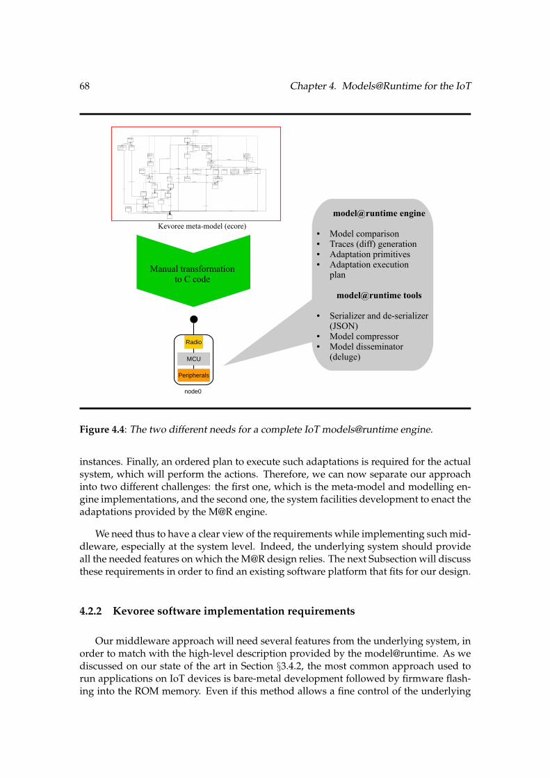
68 Chapter 4. Models@Runtime for the IoT
Channel
ChannelType
lowerBindings : EIntegerObject
upperBindings : EIntegerObject
lowerFragments : EIntegerObject
upperFragments : EIntegerObject
ComponentInstance
ComponentType
ContainerNode
ContainerRoot
DeployUnit
groupName : EString
version : EString
url : EString
hashcode : EString
type : EString
Dictionary
DictionaryAttribute
optional : EBoolean = false
state : EBoolean = false
datatype : EString
fragmentDependant : EBoolean = false
defaultValue : EString
DictionaryTypeDictionaryValue
name : EString
value : EString
FragmentDictionary
name : EString
Group
GroupType
Instance
metaData : EString
started : EBoolean = true
MBinding
MessagePortType
NamedElement
name : EString
Namespace
NetworkInfo
NetworkProperty
value : EString
NodeLink
networkType : EString
estimatedRate : EIntegerObject
lastCheck : EString
zoneID : EString
NodeNetwork
NodeType
Operation
Parameter
order : EIntegerObject
Port
PortType
synchrone : EBoolean = false
PortTypeMapping
beanMethodName : EString
serviceMethodName : EString
paramTypes : EString
PortTypeRef
optional : EBooleanObject
noDependency : EBooleanObject
Repository
url : EString
ServicePortType
interface : EString
TypeDefinition
version : EString
factoryBean : EString
bean : EString
abstract : EBoolean = false
TypedElement
TypeLibrary
[1..1] typeDefinition
[0..1] dictionary
[0..*] fragmentDictionary
[1..*] deployUnit
[0..1] dictionaryType
[0..*] superTypes
[0..*] provided[0..*] required
[0..1] namespace
[0..*] required [0..*] provided
[0..*] components
[0..*] networkInformation
[0..*] nodes
[0..*] typeDefinitions
[0..*] repositories
[0..*] dataTypes
[0..*] libraries
[0..*] hubs
[0..*] mBindings
[0..*] deployUnits
[0..*] nodeNetworks[0..*] groups
[0..*] requiredLibs
[0..*] values
[0..*] genericTypes
[0..*] attributes
[0..*] filters
[0..*] elements
[0..*] values
[0..*] networkProperties
[0..*] link
[0..1] initBy
[1..1] target
[0..*] parameters
[0..1] returnType
[0..1] type
[1..1] portTypeRef
[1..1] ref
[0..*] mappings
[0..*] operations[0..*] subTypes
[0..*] bindings
[1..1] port
[0..*] subNodes
[0..*] groups
[1..1] hub [0..*] bindings
[0..1] host
[0..*] hosts
Kevoree meta-model (ecore)
Manual transformationto C code
node0
Radio
MCU
Peripherals
model@runtime engine
● Model comparison● Traces (diff) generation● Adaptation primitives● Adaptation execution
plan
model@runtime tools
● Serializer and de-serializer(JSON)
● Model compressor● Model disseminator
(deluge)
Figure 4.4: The two different needs for a complete IoT models@runtime engine.
instances. Finally, an ordered plan to execute such adaptations is required for the actualsystem, which will perform the actions. Therefore, we can now separate our approachinto two different challenges: the first one, which is the meta-model and modelling en-gine implementations, and the second one, the system facilities development to enact theadaptations provided by the M@R engine.
We need thus to have a clear view of the requirements while implementing such mid-dleware, especially at the system level. Indeed, the underlying system should provideall the needed features on which the M@R design relies. The next Subsection will discussthese requirements in order to find an existing software platform that fits for our design.
4.2.2 Kevoree software implementation requirements
Our middleware approach will need several features from the underlying system, inorder to match with the high-level description provided by the model@runtime. As wediscussed on our state of the art in Section §3.4.2, the most common approach used torun applications on IoT devices is bare-metal development followed by firmware flash-ing into the ROM memory. Even if this method allows a fine control of the underlying

4.2. Kevoree for the IoT 69
hardware, the development time can be very long and difficult to debug, since abstrac-tions are mostly done only at the hardware level, and does not come to the system level.Moreover, since complexity grows, applications for IoT should be developed withoutspecial attention to hardware and system concerns. Thus, the use of an IoT operatingsystem seems to be the way to go, in order to take advantage of its system-level abstrac-tions.
As presented in the state of the art, several IoT operating systems exist, but accordingto the needed features some of them are more convenient. We can thus establish therequirements as following, according to OS properties:
i. Basic OS functionalities such as timers, task scheduler and Inter Process Com-munication (IPC). Basic functionalities that are the core of any embedded OS.
ii. Dynamic linker and loader, following the third approach presented in section§3.4.2. A dynamic linker and loader is essential to our approach, since changesin the model containing new software components will trigger the download andinstantiation of an artefact, which should be linked and loaded at runtime by theunderlying system.
iii. Network stack implementing basic IP functions (TCP, UDP, HTTP, CoAP). Inorder to share a model and download software artefacts, IP communication ismandatory, since the goal is to use the Internet to reach component repositoriesfrom different sources.
iv. Persistent data handling, preferably a file system. The method used to avoidRAM storage is to serialize the model@runtime in a file on the flash memory, usu-ally in the JSON format. Thus, a way to store and access this JSON file for readingand writing should be provided.
v. Abstractions for attached devices (LEDs, sensors, actuators, etc.). Although notmandatory, an OS usually carry basic hardware abstractions, providing an easyway to develop applications which need a physical interaction with the externalworld.
In order to make a rapid functional prototype of our middleware, we will make use ofthe Contiki OS which, given the features presented above, seems to fit our minimal re-quirements. Despite the programming model already described as a drawback, Contikioffers all the needed functionalities, as well as a wide community which collaborate veryactively in the development and debug of it. Moreover, Contiki includes an implementa-tion of 6loWPAN [76], an adaptation layer for an IPv6 compressed stack, which let us as-sign directly an IPv6 address to the device. This enables a ready to use IoT environment.Afterwards, an UDP transport layer is provided, allowing a standard way to reach UDPservers to download the needed deploy units to perform system adaptations, accordingto the model@runtime engine. Indeed, one of the most important features provided bythis OS is the dynamic code loading mechanisms. These are based on a dynamic linkerand loader that use the standard ELF object file format [31].
70 Chapter 4. Models@Runtime for the IoT
4.3 Networking aspects on IoT environments
Regarding the inter-node challenge, another concern while adapting the selected fea-tures of the Kevoree M@R implementation is the amount of energy needed to run it.Indeed, an IoT device running on batteries should be able to embed this middlewarewithout a high overhead in terms of energy consumption. Since the most processorconsuming tasks are model checking and adaptations execution, a smaller overhead isinduced, compared to the traditional approach, thanks to the simplification of such pro-cess. However, it was discussed that the most energy consuming task for an IoT device isthe radio communication. This rises new and different challenges while interconnectingour nodes running the adapted Kevoree implementation, since the traditional Kevoreeimplementation was done having in mind no restrictions for network usage and band-width, thus algorithms such as Gossip [44] were used for model dissemination. Theimplementation of such a protocol in an IoT device could be very memory consuming,in addition to a high-energy consumption while using the network.
Given the energy and memory constraints, a dissemination protocol adapted for IoTdevices is then needed. It results interesting that the already described Deluge protocol[60] seems to be a good option, since it was developed having in mind the constraints ofan IoT device. Even if it was presented as a bad choice while performing entire firmwaretransmissions, the model information to be shared is not as big as an entire firmware, butrather a small serialized file, thus the needed energy to disseminate a model is actuallyvery low.
A last concern should be taken into account while performing adaptations. We ob-served that the adaptation process would need to download new deploy units to beinstantiated according to the new requirements, or when an update is needed. Indeed,the traditional Kevoree approach will download all needed software artefacts from aregistered repository, without any care about the network topology. However, since thenodes on the IoT can form very different and complex network topologies (multi-hopmesh, stars), we need to analyse several strategies to reduce network traffic as much aspossible. Therefore, the need of a more complex technique to download software arte-facts appears, in order to reduce the inherent energy consumption while performing thistask.
4.4 Summary
At this point, we can highlight the main requirements and functionalities neededfrom a typical IoT device, in order to run a models@runtime implementation. We cannow observe that the challenges are concentrated on the internal behaviour of an IoTnode, thus focusing only in providing an intra-node implementation. This intra-nodeview will guide us to put our efforts into a first proposal of the Kevoree-IoT middleware,taking into account all the design requirements exposed throughout this chapter.
It is important to notice and remember that our environment is very constrained,

4.4. Summary 71
first in the intra-node perspective but also in the inter-node mechanisms. Indeed, we canremember our challenges as following:
i. Intra-node challenges: Memory, processing, storing and programming environ-ment constraints.
ii. Inter-node challenges: Networking, thus communication, which impacts primarythe energy consumption.
The next chapter will provide the implementation details of our intra-node designspecifications, followed by an evaluation of the possibilities and limitations of our ap-proach. Since our goal is to provide a middleware that works on real platforms, ourevaluations were conducted, first, on an especially designed hardware platform. More-over, once our first tests are analysed, we followed our research goals by testing ourimplementation on a large-scale testbed. Indeed, this last evaluation will trigger the ac-tual challenges for the inter-node needed mechanisms, which will be presented in thechapter afterwards.

72 Chapter 4. Models@Runtime for the IoT

Chapter 5
Intra-node challenges: middlewareimplementation and evaluation
As we discussed on the previous chapter, the presented design of our middlewareshould be able to represent a running system in the form of a model@runtime, accord-ing to the Kevoree meta-model. Indeed, this representation can be manipulated by theexisting Kevoree editor, on which we can modify parameters, add or remove nodes andcomponents or bind component’s ports using channels. Therefore, we focus on the intra-node challenges first, by implementing our middleware on real hardware, leveraging ourdesigned platform and existing OS facilities.
In this chapter, we will first explain how the model@runtime can be represented onthe IoT device limited memory, as well as the model analysis and manipulation. Indeed,as we stated previously, our middleware should also be able to interoperate with the ex-isting Kevoree implementations, in order to achieve interaction with other participantson the internet, such as cloud services, existing distributed applications or simply datamining on remote servers and clients. Therefore, the standard Kevoree model represen-tation, in the form of a serialized JSON format, is a must-have for our implementation.This rises several challenges in how a ”big” (to be saved RAM) representation of themodel can be stored and accessed on our constrained nodes. We will present how wecope with this challenge, from the representation of objects in a procedural languagesuch as C, to the manipulation techniques used to compare and execute the actions de-scribed on the models.
Experiments were conducted to evaluate the functionalities and the scalability of ourapproach, and the results are presented at the end of the chapter. First, a generic im-plementation is tested on a single ”big” node, followed by scalability experiments ona typical node present in a large-scale testbed. Our main goal is to state the minimalfunctionalities at the model level, from which we can then implement the needed mech-anisms to achieve real reconfigurations and adaptations described in the new upcomingmodels.
74 Chapter 5. Intra-node challenges: middleware implementation and evaluation
5.1 An empirical study on constrained IoT devices
The model@runtime paradigm has been mainly investigated in the context of dis-tributed systems. These research efforts have been focused on the provision of a compre-hensive set of tools to easily deploy, dynamically reconfigure, and disseminate softwareon a set of distributed computing units. The current model@runtime tools have beenimplemented regardless of the specific characteristics and constraints of IoT devices. Inparticular, the network topology and the resource constraints of the nodes forming thedistributed system have not been taken into consideration. As a result, state of the artmodel@runtime tools are not suitable to be used in the context of IoT Systems.
In [45] µ-Kevoree, the closest effort to port the model@runtime paradigm on the con-straints of a Cyber Physical System (CPS) was presented, in which the underlying deviceis comparable to an IoT device. Despite the particular attention given to the specific con-straints of a Cyber Physical System, this work heavily relies on over the air firmwareflashing to support the deployment and reconfiguration of software. We consider thatrelying on firmware flashing to support software deployment constitutes a flaw in theapproach because of its energy cost (the complete firmware has to be sent, and if anyerror occurs, the whole process is restarted). A second limitation of this approach lies inthe fact that each resource constrained node relies on a more powerful node to performmost of its tasks related to the dynamic reconfiguration (firmware synthesis, reconfigura-tion decision and so on). This second limitation is not suitable in the context of a systemmainly composed by resource constrained nodes since all these nodes have to be man-aged by bigger nodes. Pushing this idea further, the management of a CPS composed ofa wide number of resource constrained devices and a bigger node, the latter will have tomanage all the smaller devices in a centralized management scheme.
The next section will describe a more complete M@R engine implementation basedon the Kevoree meta-model, together with some tools which allow model manipulation.
5.1.1 Kevoree-IoT: Estimating needed resources
In contrast with most of the current implementations of the M@R paradigm, whichare intended for high resources machines thus they make use of high-level programminglanguages, our first implementation should follow a procedural language such as C. Wecan justify this by the fact that most of the open source compilers for IoT devices supportonly this programming language, in addition to C++. However, C++ applications aredifficult to integrate in OSs like Contiki or RIOT, which are convenient OS able to runour middleware. Thus, a first approach has been developed in plain C†1 following thedirections presented in Section §4.2.
Indeed, our efforts were put into a first manual implementation of the Kevoree meta-model. The size of the test application which contains a group and a node without com-ponents is of 181997 bytes, while the needed RAM before the execution is of 1616 bytes.
†1https://github.com/kYc0o/kevoree-c

5.1. An empirical study on constrained IoT devices 75
Figure 5.1: Graphical representation of a minimal M@R.
A graphical representation of the model can be obtained through the Kevoree Web Ed-itor†2, in which a serialized JSON file containing the model can be loaded for edition.This representation is shown in figure §5.1.
Then, it is necessary to characterize the minimum system requirements for an IoTdevice to implement a full model@runtime middleware, as in hardware capabilities as inexecution environment. This will avoid the use of third party nodes to perform the high-level tasks described above. However, even if a proposed device meet the characteristicsto perform such tasks, the trade-offs between energy consumption and the middlewareexecution should be taken into account. A general description of needed features toexecute the proposed middleware is given in the next subsection.
5.1.2 Handling hardware constraints
Considering the challenges presented in Section §4.2, we must test our implementa-tion on real hardware platforms in order to measure the limitation of our approach, aswell as its compatibility with the other implementations (Java, Cloud, Android). More-over, the energy constraint of each IoT node, together with the mesh topology of thenetwork makes communication in these environments fairly reliable. This implies thenecessity to optimize the way the model and the software are disseminated on the net-work.
At first glance, our implementation was compiled for three different platforms (class1 [11] ): the zolertia Z1†3, redbee econotag†4 and wismote†5, which were widely used forresearch purposes in the IoT domain. Unfortunately, none of these platforms was ableto meet the space requirements in ROM and RAM to run a minimal model at runtime asshown in figure §5.1. However, the existence of more powerful microcontrollers, an es-sential part of an IoT device, shows that typical IoT applications have not exceeded theresources of existing experimentation platforms. Indeed, only some development kits
†2http://editor.kevoree.org/v4/†3http://zolertia.sourceforge.net/wiki/images/e/e8/Z1 RevC Datasheet.pdf†4http://redwire.myshopify.com/products/econotag-ii†5http://wismote.org/doku.php

76 Chapter 5. Intra-node challenges: middleware implementation and evaluation
such as TI’s CC2538DK†6 were available at that time, but its high cost, low availabilityand poor support gave low acceptance for research purposes. Thus, the design and con-struction of a new experimentation platform seemed to be the fastest way to obtain thefirst results of the implementation, by integrating the latest microcontrollers and periph-erals available on the market. It is worth to consider that this platform was conceived forresearch and experimentation purposes, and not as an end-user device.
An exhaustive search was conducted to find the latest technologies to build an exper-imentation IoT device, which fits the requirements already estimated in section §5.1.1.The first step was to find the basic components of such a device. Taking into account therequirements from section §4.2.2, an IoT device should, more specifically, embed:
i. Microcontroller. A low-power microcontroller unit is needed to perform the com-putational processing tasks as well as to store the program code. A huge amount ofROM and RAM is needed at the scale of these devices; thus, it is necessary to finda microcontroller with a good trade-off between energy consumption and memorysize.
ii. Communication interface. Communication is the main task that will perform ourdevice, since it is mandatory for IoT environments. A radio interface implementingthe widely-used IEEE 802.1.5.4 standard [1] is then necessary to communicate inan interoperable way with other devices. An ultra-low energy consumption is alsoimportant, since communication is the most energy consuming task.
iii. External flash memory. Storage for data is a very useful feature for an IoT device.It can serve as persistent data storage for logging and data collection from sensors,as well as updates and eventually new firmwares.
iv. Sensors and actuators. In order to collect experimentation data, some sensorsshould be embedded on the device, the most common being temperature, humid-ity and position. Indicator LEDs are also commonly present in these devices, toprovide visual signs such as function status (ON/OFF) or current communication.
v. Ports for external devices. An easy way to connect third party devices allows a dy-namic behaviour, since we can connect other sensors, actuators and devices whichcannot be present internally on the device. Such devices should be connected usingstandard interfaces, such as I2C and SPI. General Purpose Inputs/Outputs (GPIO)are also widely used, either as digital or analogue interfaces.
vi. Battery capabilities. An IoT device is very often used in environments where aconstant power source is not present. Thus, work on batteries is a very usefulfeature to test energy consumption while adding flexibility of placement.
Given these features, it was then necessary to integrate several components in orderto build the required IoT device. We put special attention to the most critical components,which are the microcontroller, the external flash memory and the battery controller. Re-garding the radio transceiver and the other peripherals, there are no huge differences
†6http://www.ti.com/tool/cc2538dk

5.1. An empirical study on constrained IoT devices 77
Microcontroller Speed (MHz) RAM (KB) ROM (KB) Consumptionat max. speed (mA)
STM32F0 48 32 256 22STM32F1 72 96 1024 68STM32F3 72 80 512 61.5STM32F2 120 128 1024 49STM32F4 180 256 2048 98
Table 5.1: Comparison between STM32F microcontrollers.
between the most commonly used, for instance, the ones used in the previously analyseddevices. The specific conception of the platform will be described in the next subsection.
5.1.3 Towards a new IoT device
Several low-power microcontroller architectures were available at the time of our firstM@R implementation, such as TI MSP430, Atmel AVR, Microchip PIC and ARM Cortex-M, just to mention the most common ones. Since our middleware minimum memoryrequirements were tested on 16-bit MSP430 microcontrollers (Zolertia’s Z1 and Arago’sWiseMote), finding a huge scarcity of memory, 32-bit architectures were the target ofour scope. Indeed, ARM Cortex-M microcontrollers offer only 32-bit RISC architectures,which are widely used both in research and industry. Thus, the first step was to selectan ARM Cortex-M microcontroller fitting our memory and energy consumption require-ments. The ST Microelectronics STM32 family of microcontrollers offers a wide range ofdevices with different processor speeds and memory sizes.
Since our goal is to build a device on which our experimentations could be executedon a more flexible way (without caring about memory requirements), it is preferable touse a microcontroller featuring the highest memory capabilities, both in ROM and RAM,over energy consumption. Moreover, this kind of devices are able to change the proces-sor speed as needed, thus reducing the energy consumption. Indeed, our choice was aSTM32F4 microcontroller, which was used as the core of our IoT device. Table §5.1 showsa comparison between the available microcontrollers, featuring the maximum processorspeed, RAM and ROM, followed by the current consumption in such configuration.
As for the power scheme, given the capabilities of the selected microcontroller, apower source between 1.8V and 3.6V is required. Indeed, a first approach to power thedevice is the use of an USB port, which delivers around 5V. Thus, a 5V to 3.3V (therecommended tension) is required. In contrast, when the device is needed to run onbatteries, the supplied voltage will change. A couple of AA batteries connected in seriesis the most standard array to power IoT devices. However, a wide set of peripherals

78 Chapter 5. Intra-node challenges: middleware implementation and evaluation
Speed
(MHz)
RAM
(KB)
ROM
(KB)
External
flash (MB)
Radio
transceiverPeripherals Embedded
Sensors
Zolertia
Z116 8 96 2 CC2420
UART, I2C
Phidgets
(USB only),
GPIO
3 axis acc.
and
temperature
Arago’s
WisMote25 16 256 8 CC2520
UART, I2C,
Phidgets,
GPIO
3 axis acc.
light and
temperature
Redbee
econotag26 96
N/A
(device run
from RAM)
128 (KB) Integrated (SoC) GPIO N/A
DiverSE
Board180 256 2048 16 CC2520
UART (x2),
I2C
Phidgets,
GPIO
N/A
Table 5.2: IoT Platforms comparison.
such as sensors and actuators work very often at 5V. Therefore, it was necessary to adda DC to DC converter, coupled with an automatic power selector which detects whenthe device is powered either by USB or batteries. This allows to use any power schemewithout decreasing performance or peripherals compatibility.
Thus far, the main required features for our device are met. A comparison betweenthe previously tested platforms and ours is given in table §5.2, showing the most com-mon useful features. Moreover, figure §5.2 shows the layout of the new board, on whichwe can observe the different components and the size of the PCB. Indeed, its measuresare 3.5cm x 4.5cm.
Given the features of our new IoT device, the next step is to provide the hardwareabstraction layer and a network stack to integrate it into an IoT network. Indeed, severalIoT operating systems existed at the time this device was developed, thus leveragingone of these available OS was the most recommended procedure. It is important tonotice that our middleware implementation it’s independent of the underlying OS, sinceit only provides abstractions for the representation of the running system in the formof a model@runtime. Thus, it can be adapted to any other OS able to integrate moduleswritten on C, as well as networking facilities typical of the IoT to disseminate such model.
5.2 The new Kevoree-IoT Contiki implementation
In this section, we present our initial results towards the design of a middlewarewhich will offer the functionalities of model@runtime over the previously conceived IoT

5.2. The new Kevoree-IoT Contiki implementation 79
STDIO GPIO (I2C, SPI...) Antenna
STM32F427
SWD (Programming)
Phidgets (5V/3V)
User button Reset
CC2520
16MBFlash
Figure 5.2: The new designed board to meet our needs..
device. This middleware, which we called Kevoree-IoT (in reference to the Kevoree-like M@R implementation of our middleware), will provide a development frameworkfor applications on top of these systems, and will provide the runtime infrastructure tosupport the deployment and dynamic reconfiguration of these applications.
We based our implementation on an already ported Contiki version†7 for a very sim-ilar device than ours, which provided a basic hardware abstraction layer for the radiointerface and some I/O drivers. The rest of the drivers were developed according to ourplatform hardware design. Once the porting completed the next step was to test our mid-dleware on such platform. To do that, a Kevoree-IoT application should be developed,using this new Contiki port.
Based on the Kevoree-C implementation introduced in subsection §5.1.1, the neededContiki application was developed and tested in our platform. The first implementa-tion†8 was done using the version 4 of the Kevoree meta-model. This meta-model hasbeen mapped into C code as a Contiki application. We were able to add nodes, com-ponents, groups and channels, and bind them through the Kevoree editor by loading agenerated JSON file.
†7https://github.com/vedderb/contiki†8https://github.com/kYc0o/kevoree-contiki

80 Chapter 5. Intra-node challenges: middleware implementation and evaluation
5.2.1 An object-oriented representation using C
As we discussed previously on Subsection §4.2.1, special attention must be put whiletransforming a meta-model into a procedural language such C. Indeed, this program-ming language does not have an object-oriented design, thus a representation of classes,their properties and relationships from the Kevoree meta-model should be proposed.
We took as a source of inspiration the existing Kevoree implementation for C++†9,which is the closest language that match with C. In this implementation, the classes andits relationships are transformed into C++ code directly, since it supports object-orientedrepresentations. We can observe four components in the Kevoree meta-model:
• Classes. This is the abstract representation of an object type. It can be instantiatedand contains properties and relationships with other classes.
• Properties. Values that can have the form of a primitive type (integer, character,boolean, etc.), depending on the types supported by the language. Special proper-ties called methods are also part of a class, which provide a specific functionalitywhen the method is called.
• Relationships. These are the connections between two or more classes. We cannote two types: a reference and a containment reference.
• Inheritance. A class can inherit the previously described components from anotherone, besides adding its own.
Thus, implementing this representation lead our efforts to optimize the resultingcode, while respecting the previously described composition. Indeed, the first step wasto represent a class as a C data structure. While doing it, some decisions were made inorder to cope with the intra-node constraints:
• Primitive types such as integers and boolean keep the same size as in the meta-model.
• String types are of a fixed size, to avoid dynamic memory allocation thus eventualfragmentation.
• Methods are represented as function pointers, in a separated structure called Vir-tual Table, allowing easy inheritance.
• Properties inheritance is achieved by copying the parent’s properties (includingand respecting all the inheritance hierarchy), followed by a pointer to the virtualtable. This way we can reuse code and ensure polymorphism.
• References are represented as a pointer to the referenced structure, while contain-ment is achieved using a minimalistic implementation of a hashmap.
†9https://github.com/kevoree/kevoree-cpp

5.2. The new Kevoree-IoT Contiki implementation 81
typedef char* (*fptrKMFMetaClassName)(void*);typedef char* (*fptrKMFInternalGetKey)(void*);typedef char* (*fptrKMFGetPath)(void*);typedef void (*fptrVisit)(void*, char*, fptrVisitAction, fptrVisitActionRef, bool);typedef void* (*fptrFindByPath)(void*, char*);typedef void (*fptrDelete)(void*);
typedef struct _KMFContainer_VT {void *super;/** KMFContainer_VT*/fptrKMFMetaClassName metaClassName;fptrKMFInternalGetKey internalGetKey;fptrKMFGetPath getPath;fptrVisit visit;fptrFindByPath findByPath;fptrDelete delete;} KMFContainer_VT;
typedef struct _KMFContainer {KMFContainer_VT *VT;/** KMFContainer*/KMFContainer *eContainer;
} KMFContainer;
Listing 5.1: KMFContainer: the main container on Kevoree
typedef struct _NamedElement_VT {KMFContainer_VT *super;/** KMFContainer* NamedElement*/fptrKMFMetaClassName metaClassName;fptrKMFInternalGetKey internalGetKey;fptrKMFGetPath getPath;fptrVisit visit;fptrFindByPath findByPath;fptrDelete delete;
} NamedElement_VT;
typedef struct _NamedElement {NamedElement_VT *VT;/** KMFContainer*/KMFContainer *eContainer;/** NamedElement*/char name[16];
} NamedElement;
Listing 5.2: NamedElement class representation inheriting from KMFContainer
We can observe on listing §5.1 the representation of the main Kevoree class KMFCon-tainer which includes only a pointer to its container and a pointer to the Virtual Tablecontaining the function pointers to its methods. As an example, the class NamedElementin listing §5.2 shows how inheritance is achieved, by copying the property of the parentclass. On the other hand, method inheritance is achieved by copying all the function
82 Chapter 5. Intra-node challenges: middleware implementation and evaluation
pointers into its own virtual table. Moreover, to access parent’s method implementation,the virtual table contains also a pointer to its parent (super class).
Once a representation of the basic requirements is implemented, we need to pro-vide mechanisms to represent an instantiated model using the data structures describedpreviously. The next Subsection describes briefly how the process of serialization andde-serialization takes place.
5.2.2 Model manipulation challenges
While representing an instantiated model in memory, we need to allocate enoughplace for the required nodes, components and connections that are described in a seri-alized form. This starts by a model de-serialization, which consists in the transfer of aJSON file among the nodes in the network, followed by the model parsing and executionof the adaptations and reconfigurations described on it. Due to memory limitations, amodel cannot be loaded entirely, thus mechanisms to partial loading and parsing shouldbe provided. Indeed, a very efficient JSON loader was developed to fit the memoryconstraints. This loader takes the JSON elements one by one directly from the externalflash, thus avoiding the allocation of big memory slots, and freeing the already parsedelements. Once an element is loaded, it is compared with the current status of the system(the running model being de-serialized at the same time), generating a list of differences(traces about changes) which are analysed to create a list of adaptations and reconfigu-rations.
The execution of the adaptations and reconfigurations will use the features providedby the underlying system, which were already presented in section §4.2.2.
5.3 Firsts evaluations of the approach
Our firsts results showed that our implementation was able to run on our experimen-tation device. This first firmware contains the Contiki OS kernel, device drivers, a CoAPweb server and the Kevoree-IoT middleware. The memory size of this firmware is of215228 bytes in ROM and only 18404 bytes in RAM.
Once our middleware was running in our experimental platform, we needed to testit at large scale in order to test the model dissemination. This needs a large infrastructurewith several devices where a basic experiment using our middleware can be executed.Indeed, the manufacturing of several of our devices was our first option. However, sincethe manufacturing of the firsts devices was made by hand, to build some other a hugeamount of time was needed, and could be very costly. Therefore, a search for large-scale testbeds for the IoT was done. The next section will describe one of the platformsavailable in a large-scale testbed, showing its main characteristics, which were analysedin order to find if they met our requirements.

5.3. Firsts evaluations of the approach 83
5.3.1 Requirements for large-scale evaluation
At the time of our firsts experiments, a testbed existed at the INRIA Rennes cen-tre, where our research team is based. A Wireless Sensor Network called Senslab [25],formed by 256 devices was deployed in a centre’s cellar. This WSN offered wireless sen-sors of similar characteristics as the Z1 platform, which was already described. Thus, theminimum requirements to run our middleware were not met by these WSN’s devices.However, an extension of such testbed was done recently, adding new experimentationplatforms. This new platform, called FIT IoT-Lab [41], featured new devices of a similararchitecture as ours. Indeed, two more powerful nodes were added to the testbed: theM3 node and the A8 node, in order to provide more powerful IoT capabilities.
Figure 5.3: The FIT-IoT Lab M3 Open Node.
Figure §5.3 presents the M3 Open Node, an IoT device with very similar character-istics of the one from our design. This device features a STM32F1 Cortex-M3 microcon-troller, with 512KB of ROM and 64KB of RAM. External sensors are available, as well as3 LEDs. The communication is handled by an AT86RF231 radio, implementing the stan-dard IEEE 802.15.4, typical of IoT devices. In addition, a Contiki port for this device wasalready available, facilitating the integration of our existing implementation for Contiki.This combination seems suitable for our experiments, since our firsts results showed thataround 200KB of ROM and 16KB of RAM were enough to run a minimal implementationof our middleware, including the kernel, communication stack and peripheral drivers.
The next subsection will give details about the technical contributions provided forthe IoT-Lab testbed, in order to have a complete IoT platform able to run our middlewareand ready for our large-scale tests. Indeed, testing on a large-scale testbed facilitates thefirmware flashing, serial output for debugging and power monitoring, thanks to the
84 Chapter 5. Intra-node challenges: middleware implementation and evaluation
tools provided by IoT-Lab†10. Moreover, a Contiki port is maintained and supportedby the IoT-Lab team, providing a ready to use environment for our already developedtools. However, two important features lacked in this port: the low-level interface forthe Contiki File System (CFS) and the relocation operations needed by the Contiki ELFloader. Therefore, given the importance of these features for the correct implementationof our middleware, it was necessary to extend the testbed capabilities to add support forthe CFS and the ELF loader.
5.3.2 Extending the FIT IoT-Lab testbed
As stated previously, two missing features were detected in the Contiki port madefor this testbed. The first one was the implementation of a low-level interface necessaryfor the Contiki File System. This driver make use of low-level functions to read, writeand erase the flash memory embedded on the M3 node. Therefore, this functionality isnecessary to leverage the high-level abstractions provided by the CFS, which are a veryuseful approach to manipulate files into the flash memory, also needed by the ELF loader.
5.3.2.1 File system driver implementation
The definitions and porting instructions for CFS can be found on the wiki page of theContiki main repository†11 as well as in the article introducing this file system in [102].A brief description of the file system is given as follows:
Contiki provides a set of file systems for using various kinds of storage devicesin resource-constrained systems. All of these file systems implement a subset ofthe Contiki File System (CFS) interface, and two of them provide the full func-tionality: CFS-POSIX and Coffee. CFS-POSIX is used in Contiki platforms thatrun in native mode. It uses direct calls to the POSIX file API that is providedby the host operating system. Coffee, on the other hand, is primarily aimed atsensor devices that are equipped with flash memories or EEPROM.
Thus, the usage of the Coffee API is the one that should be implemented for theM3 platform. To do so, information about the flash memory embedded on the platformmust be mapped into the configuration headers used by Contiki, in order to provide aconnection between the physical device and the OS. This information consists in severalparameters, such as:
Total size. The actual size of the memory flash.
Sector size. A flash memory is divided by sectors. This information allows the CFS toorganize the way the memory will be written.
†10https://www.iot-lab.info/tools/†11https://github.com/contiki-os/contiki.git

5.3. Firsts evaluations of the approach 85
Page size. This parameter is given by the manufacturer of the flash memory and allowsto organize writing cycles in a more efficient manner, avoiding fragmentation.
Coffee start. It describes the actual memory address where Coffee can start to write. Itallows to reserve a memory space that cannot be accessible from the API, providinga secure space where we can store read-only data (i.e. initialization data, node ID,etc.).
Coffee size. This is the overall memory available for reading/writing using Coffee. It iscalculated by the difference between the total size and the Coffee start size.
Coffee name length. With a view on internal memory savings, a limitation on file namesis imposed. This will avoid the use of large filenames which have an impact on thememory footprint of the CFS.
Coffee max. open files In the same way as name length, the number of simultaneousopen files can increase the memory usage by the file system. Thus, a limitation onthis concern is needed.
Afterwards, parameters to configure the internal behaviour of Coffee are needed, inorder to provide more or less flexibility on the usage. Those parameters are set on themaximum optimal levels for our platform, in order to give the maximum flexibility aspossible.
Once the flash parameters are given, some functions allowing the actual read-/write/erase onto the flash memory must be also mapped in the interface. Thus, func-tions from the lower driver implementation are needed. Indeed, these are provided bythe Hardware Abstraction Layer, already included in the IoT-Lab low-level driver im-plementation. This HAL is included in a separated repository called openlab †12. Withinthis repository, all the low-level drivers providing functions to manipulate every pieceof the embedded system are included.
Once the porting of the file system is done, we can take care about the ELF loader.This second technical contribution aims to provide the relocation functions for the em-bedded ARM Cortex-M3 CPU, used by the Contiki ELF loader in order to find the correctaddresses of the symbols provided by the OS. Indeed, the ELF loader is the main featureused to add new modules to the kernel or update its existing features.
5.3.2.2 Runtime address relocation for ARM Cortex-M3 platforms
As presented in section §3.4.2, we have studied the different methods to add newmodules into a running IoT device. The method used by the Contiki ELF loader is therelocatable code. Indeed, this approach needs to relocate the temporary addresses givento the unresolved symbols of a new module, in order to get access to the needed functionsprovided by the OS.
†12https://github.com/iot-lab/openlab.git

86 Chapter 5. Intra-node challenges: middleware implementation and evaluation
Since the use of the Contiki ELF loader involves two aspects, a prepared firmwareable to load new modules and the new modules themselves, modifications to the compi-lation routines should be provided for both artefacts As described in the Contiki wiki†13,a firmware able to load new modules should be prepared as follows:
The firmware must be prepared with a symbol table to able to load ELF mod-ules dynamically. This three-step process ensures that all available symbols inthe firmware are also visible in the symbol table, along with a pointer to theiraddress.
make <firmware-name>make CORE=<firmware-name> <firmware-name>make CORE=<firmware-name> <firmware-name>
Thus, compilation instructions for the CORE variable must be provided. Since they areCPU specific, they must be added in the Makefile for our specific platform.
ifdef CORE.PHONY: symbols.c symbols.hsymbols.c:$(NM) $(CORE) | awk -f $(CONTIKI)/tools/mknmlist > symbols.celsesymbols.c symbols.h:cp ${CONTIKI}/tools/empty-symbols.c symbols.ccp ${CONTIKI}/tools/empty-symbols.h symbols.hendif
Listing 5.3: Compilation settings to create a proper symbol table
Listing §5.3 shows the instructions to create a symbol table for the M3 platform, in-cluding all the functions used in the base firmware. These symbols are created usingthe arm-none-eabi-nm command to extract all the symbol’s names from the mainfirmware, and with the aid of a Contiki tool called mknmlist a source C file is generatedwhere all used symbols are declared. Finally, this source code is compiled and linkedto the main firmware. On the other hand, if the CORE variable is not set, a predefinedsource file without the symbols is copied to be compiled with the main firmware.
As for the creation of new ELF modules, the Contiki dynamic linker and loader [31]depends strongly on the relocation methods supported by the CPU architectures forwhich the module is being compiled. Since our implementation is based on an ARMarchitecture, we need to provide the relocation functions for this platform. Indeed, ARMoffers the processor-specific definitions in the ELF for the Application Binary Interface(ABI) for the ARM architecture†14 document. This document specifies the way of an ELFbinary should be produced by a compiler, including the relocation types. Thus, this in-formation should be used to implement a dynamic linker which will be in charge of therelocation process for unresolved symbols present in the new module. For the ARM ar-chitecture, more than 100 relocation types exist, but just a few operations stills relevant.
†13https://github.com/contiki-os/contiki/wiki/The-dynamic-loader#Preparing a Firmware for ELF Loading†14http://infocenter.arm.com/help/topic/com.arm.doc.ihi0044e/IHI0044E aaelf.pdf

5.3. Firsts evaluations of the approach 87
We will focus in only 3 types of relocation, which were present in most of the exampleswe compiled. These relocation types are presented in table §5.3.
Code Name Type Class Operation
2 R ARM ABS32 Static Data (S + A) — T
10 R ARM THM CALL Static Thumb32 ((S + A) — T) – P
30 R ARM THM JUMP24 Static Thumb32 ((S + A) — T) – P
Table 5.3: Relocation types compatible with our loader.
These three relocation types are the most commonly found in small component exam-ples, although 10 and 30 share the same operation. Indeed, these binary operations arethe most important part of our implementation, and were coded on our platform-specificdriver for Contiki.
Afterwards, the requirements of an ELF module handled by the Contiki ELF loaderare stated on the Contiki’s wiki, as following:
An ELF file consists of a header followed by a set of sections which typically in-clude at least a section for binary code (.text), a section for statically allocateddata with pre-assigned values (.data), and a section for zero-initialized data(.bss). Additionally, each symbol is represented in a symbol table (.symtab),and strings are stored in a string table (.strtab). For a file to be accepted byContiki’s ELF loader, it must contain at least the sections listed above.
In order to produce an ELF file compatible with these characteristics, we need toprovide the compilation recipes following the method specified by Contiki. Indeed, theContiki’s documentation provide a generic method to produce a Contiki ELF module(CE), as stated below:
Contiki’s build system includes an easy method to create modules that can beloaded into a running Contiki system. Simply compile the program with thesuffix .ce, as shown below. The suffix instructs the make program to compilean ELF file from a C source file. The object module is stripped from unneededsymbols. The .co suffix works similarly, but does keeps unneeded symbols inthe ELF file.
cd example/hello-worldmake TARGET=sky hello-world.ce
This method makes use of Contiki’s predefined compiler flags that should produce acompatible ELF file. However, such flags are intended mostly for MSP430 architectures.We have experimented these default flags for the CE compilation and it was found that

88 Chapter 5. Intra-node challenges: middleware implementation and evaluation
several other sections were present in the ELF file. These ”extra” sections containedneeded information about the module, and were skipped by the ELF loader. Thus, spe-cific compilation mechanisms shown on listing §5.4 have been proposed to solve thisproblem.
CUSTOM_RULE_C_TO_CE = "defined"%.ce: %.c@# Requires ’-DAUTOSTART_ENABLE’ to be loaded$(CC) $(CFLAGS) $(OPENLAB_INCLUDE_PATH) -DAUTOSTART_ENABLE -c $< -o $*.o$(GCCPREFIX)-ld -r -T $(OPENLAB)/merge-segments.ld $*.o -o $@$(STRIP) --strip-unneeded -g -x $@
Listing 5.4: Compilation instructions to generate an ARM ELF file.
We can highlight that a special linking phase (triggered by the -ld flag) using a linkerscript was needed to merge the extra sections generated by the standard compilationphase, followed by the stripping mechanism for unneeded symbols (mostly debug sym-bols). This script consists in merge all .text, .data, .rodata and .bss relatedsections into common, unified ones. This is needed for the ELF parser provided by Con-tiki, which is intended to only parse the sections mentioned above.
Once the correctness of the ELF file is validated by the loader, a relocation phase isconducted. This makes use of the ELF loader internals, which should be defined by theplatform. These steps are described by Contiki as follows:
Each CPU architecture in Contiki that supports ELF loading implements a setof architecture-dependent functions. The table §5.4 shows the API that needs tobe implemented in order to support ELF loading. These include functions al-locate RAM for data (elfloader arch allocate ram()), allocate read-onlymemory (ROM) for code (elfloader arch allocate rom()), write to the al-located ROM (elfloader arch write rom()), and relocate addresses in theROM (elfloader arch relocate()). The relocation information is stored inobjects of type struct elf32 rela, which is defined below in listing §5.5. Inthis structure, r offset indicates the location to be relocated, r info specifiesthe relocation type and symbol index, and r addend is the value to add whenrelocating an address in elfloader arch relocate().
elfloader arch allocate ram(int size) Allocate RAM
elfloader arch allocate rom(int size) Allocate ROM
elfloader arch write rom(int fd, unsigned short textoff, unsigned int size,char *mem)
Program ROM.
elfloader arch allocate relocate(int fd, unsigned sectionoffset, char *sec-tionaddress, struct elf32 rela *rela, char *addr)
Relocate addresses in ROM
Table 5.4: The architecture-dependent functions in the ELF loader.
struct elf32_rela {elf32_addr r_offset;

5.4. Evaluation of Kevoree-IoT on the IoT-Lab testbed 89
elf32_word r_info;elf32_sword r_addend;};
Listing 5.5: The 32-bit ELF relocation structure
These architecture-dependent functions were implemented for the common openlabplatform. Moreover, for the allocation ROM and RAM functions, a pre-allocated spaceof both was necessary, which was declared in the configuration header for the IoT-LabM3 platform. The source code is available in the master branch of the Contiki port forthe IoT-Lab testbed.
Finally, once all symbols are located in the right place and the code is copied into itsrespective memory space, an entry point to the new module is provided as a new Contikiprocess. Indeed, this new feature is available on the list of processes, and is now possibleto access it by using events. The Contiki message passing mechanisms are used to accessthe new provided functionalities, if needed. In a common module loading behaviour,the new process will start automatically as if it was embedded from the beginning.
The next section will describe a first evaluation of our middleware, using as examplean application which will receive a new model, make the comparison and then producethe actual changes (adaptation plan) described on the differences between an old and anew proposed model, on top of this already described IoT device.
5.4 Evaluation of Kevoree-IoT on the IoT-Lab testbed
This section presents the experiments conducted to evaluate our framework de-scribed in subsection §5.2. The goal of this evaluation is to assess the feasibility of usinga model@runtime implementation on IoT devices. In these experiments, we focus onmeasuring the overhead induced by our middleware, in order to evaluate its overheadsin memory usage and in energy consumption.
5.4.1 Experimental overview
As presented in Subsection §4.2.1, our model@runtime design has been divided intotwo main aspects: the actual model representation (through the Kevoree meta-model)and the model manipulation engine (Kevoree-IoT). Indeed, our first goal is to assess themain functionalities on the model representation and manipulation, since these are thecore of our middleware.
Therefore, this evaluation focuses on answering the two following research ques-tions:
RQ1: Does the overhead induced by our models@runtime implementation fit theresources constraints?
90 Chapter 5. Intra-node challenges: middleware implementation and evaluation
RQ2: Is this resulting overhead small enough to allow scalability?
To answer these questions four experiments are performed using the following met-rics:
• Start-up delay: time needed to load the current model. To measure this time, weevaluate the time in milliseconds until the application is ready to work.
• Consumption overhead: amount of energy in joules drawn by the node while run-ning our firmware. This energy is measured using IoT-Lab tools.
• Memory: amount of memory used by our model representation and modellingtools. Such memory is measured by comparing both flash and RAM between var-ious firmwares implementing our middleware, and another one without this im-plementation.
5.4.2 Experimental setup
We compare the performances of two different firmwares, in order to measure theoverheads induced by our M@R layer.
• The first firmware consists in a simple Blink/COAP application, with the networkstack and a CoAP server initialized. This application features a LED that startsblinking from the beginning of the experiment. The CoAP server represents a stan-dard way to communicate with the node, and it’s used to control the LED and getinformation about the sensors.
• The second firmware includes the same functionalities but is being represented bythe model at runtime. For this purpose, we add our model@runtime platform inorder to get a model reflecting the current state of the Blink/COAP application. Todo so, a basic model is built from the current system, representing the Blink/COAPapplication as a component instance.
In this experiment the two firmwares are uploaded on an IoT-Lab node and the ap-plications are executed during one minute. To evaluate the overhead of our middlewarethe two firmwares are compared with respect to:
• memory consumption both in ROM and RAM,
• the energy consumption,
• and the start-up delay.
The results of this experiment are shown in Table §5.5.
As it can be observed from the table, the usage of a model@runtime has a visibleoverhead on the memory both in ROM and RAM. This overhead is due to the code of

5.4. Evaluation of Kevoree-IoT on the IoT-Lab testbed 91
Memory used Energyconsumption
Start-updelay
ROM(in bytes)
RAM(in bytes)
Joules Msec.
Blink +CoAP
79344 13244 9.6 0
Kevoree +Blink +CoAP
112724 15822 9.606 39.1
Table 5.5: Memory use for the Blink/COAP example.
our middleware for the ROM part and to the model loaded in memory for the RAMpart. We consider that this memory overhead is reasonable compared to the benefit ofenabling an abstract representation of the current system.
Our approach also impacts the start-up time and causes a very small delay before theapplication is ready. This delay is measured using timestamps. It is due to the time usedby the processor, in order to load a model@runtime from the current application. Thisdelay is considered reasonable as it is very small and it only impacts the initial loadingof the application and has no effect during the normal operation.
As shown on table §5.5, the overhead of our framework on the energy consumptionis very low. This consumption has been measured using the data generated by the IoT-Lab platform, which includes voltage and power used by the node in an experiment. Theenergy consumption overhead, shown in Table §5.5, is obtained as a product of the powerin watts used by the node while loading the model@runtime, and the time needed beforethe application is ready and the LED is blinking. The overhead on energy consumptionis only due to the extra computing power needed in the start-up phase to load the modelin memory.
This overhead evaluation highlights the feasibility of implementing a completemodel@runtime middleware on IoT devices. The memory overhead is reasonable andfits with the resource constraints of the IoT nodes. We consider that the critical overheadfor such system is the energy consumption, and our results show that it is marginallyimpacted by our middleware.
5.4.3 Scalability
In this experiment, we evaluate the scalability of our approach by focusing on thememory needed to represent a large model. To do so, we first measure the memory size

92 Chapter 5. Intra-node challenges: middleware implementation and evaluation
without any model loaded in node’s memory. The command size of the ARM compilerwas used to obtain that measure, since this application does not need dynamic memoryallocation.
Our goal is to evaluate the biggest size that the model can reach. We progressively in-crease the model size by augmenting the number of nodes until running out of memory.Three variants of this experiment are run at last:
• with one component per node,
• with two components per node,
• and with three components per node.
0 10 20 30 40 50 60
050
0010
000
1500
020
000
2500
030
000
3500
0
Number of nodes
Mem
ory
in b
ytes
One component
Two components
Three components
Needed RAM in bytes for 1, 2 and 3 components
Figure 5.4: Memory overhead for 1, 2 and 3 Blink/COAP components..
Figure §5.4 shows the memory usage for each model depending on its size. Theseresults show that our current implementation enables to scale the model up to 60 nodeswith one component per node, and up to 37 nodes with three components per node.These numbers are encouraging, since some tens of nodes can enable a small IoT localnetwork, such as home, small buildings, cars, factory chains, etc.

5.5. Summary 93
5.5 Summary
Our initial results show that the models@runtime implementation is feasible for IoTdevices and there are enough resources to deploy several other functional software com-ponents. Indeed, we can observe that our overheads are small enough to affect the over-all operation of a node, while adding an abstract representation of the running system, inaddition to reconfiguration and adaptation possibilities. Since these results are promis-ing, we highlighted that our middleware is able to represent a running application byabstracting it through a component model, without an important overhead, neither inmemory nor in energy consumption. The Contiki OS provides most of the functional-ities that are mandatory for the good implementation of our models@runtime middle-ware. As we described in this chapter, two crucial functionalities were not implementedon the IoT-Lab M3 platform: The File System and the ELF Loader. Indeed, without thesefunctionalities the adaptations generated by the model@runtime engine could not be ex-ecuted. Since the goal of our middleware is to deploy new modules by the means of anELF file, these contributions are mandatory. Naturally, easy storage and access for thisfile simplifies the task of loading, by leveraging the abstractions proposed by the ContikiFile System. Moreover, by adding the relocation and dynamic linking mechanisms to theM3 platform, real deployment of new features is now possible.
The added support for the two main functionalities needed by our middleware wascrucial for the continuation of our research, since it allowed to conduct the evaluation onreal nodes. Without them, our experimentations would have stopped at the model level,without enacting the actual changes represented in the model at the system level. Therelevancy of our implementations was acknowledged by the FIT IoT-Lab maintainers,who accepted our pull-request†15 including these technical contributions in their mainfork of the Contiki repository.
In order to continue our research goals, we need to review our results and the toolsalready provided by our middleware. Indeed, several challenges were raised with theresults of our first model@runtime implementation. One of these challenges is about thecreation of components and their distribution across the network. Indeed, special atten-tion should be put on this inter-node mechanism, since we have argued throughout thisthesis that most of the energy consumption is due to radio communication, on batterypowered wireless nodes. Therefore, distributing software components on mesh topolo-gies, which are less robust than typical computer networks, raise scientific questionsabout the best method to distribute them. Thus, a distributed algorithm to downloadcomponents taking into account the inter-node network topology and energy consump-tion should be proposed. The next chapter will discuss how these components can bebuilt, and how they can be distributed in an energy-efficient manner.
†15https://github.com/iot-lab/contiki/pull/2

94 Chapter 5. Intra-node challenges: middleware implementation and evaluation

Chapter 6
Inter-node challenges: distributingsoftware artefacts
Throughout this thesis, we have noticed three important characteristics of IoT sys-tems: (1) they are distributed, (2) they include resource constrained nodes especially inmemory and energy and (3) they are heterogeneous both in hardware infrastructure androle in the network. Indeed, the heterogeneity is an important factor as it encompassesthe hardware and software layer: each node composing the network has its own rolein it, and thus its specific hardware and software configurations which will evolve overtime. As we presented in the introduction of chapter §4, solutions from the domain ofSoftware Engineering can deal with this problem, but cannot be seamlessly adapted tofit with all the characteristics of an IoT system, especially with the resource constrainednodes. Therefore, a first approach is to propose a way to decompose these systems intocomponents, leveraging the benefits argued by CBSE. This was already discussed in theprevious chapters, showing that a model@runtime can represent this decomposition inthe model. However, decompose this software in components raise the question abouttheir distribution in a typical IoT network.
As a consequence, in this chapter we will address the following scientific problem:How to efficiently distribute, deploy and configure software components for IoT de-vices?
Following our initial experiments presented in the chapter §4, our M@R implemen-tation provides an abstraction layer (which is simpler and safer to manipulate than theactual system) to tame the complexity of software adaptation in a distributed system.The software layer is represented as a set of interconnected components which are thendeployed and configured on each node. Following this approach, deploying and recon-figuring software requires distributing the code of the specific software components tothe targeted nodes. Currently, state of the art approaches to disseminate code over theair are limited in their ability to select specific targets (they disseminate the same binaryto every node in the network [60]), and thus waste energy when all nodes do not presenta homogeneous software layer. Another approach called FiGaRo [80] propose the useof rules to filter nodes regarding its use or current capacities, in order to select some of

96 Chapter 6. Inter-node challenges: distributing software artefacts
them for an update or new deployment, thus a fine selection of a specific node becomescomplicated.
In this chapter, we present an extension on the use of models@runtime to representboth the network and the application layer of the Internet of Things systems. At runtime,we leverage these models through a new algorithm to distribute a software componentonly to those devices that need it, providing a fine selection by manipulating the modeldirectly. Moreover, this new algorithm aims at minimizing energy consumption dur-ing the whole reconfiguration and adaptation step, proposing a distribution mechanismwhich performs this task in a very efficient manner.
6.1 Inter-node challenges
When changes in the model are disseminated in the IoT system, each node will adaptits local state to the new requirements. Indeed, this adaptation can include the deploy-ment of one or several new components, as depicted in Figure §6.1. Moreover, a givencomponent is not necessarily needed by all nodes in the network. Is in this part wherestate of the art algorithms to disseminate code over multi-hop WSNs are limited, sincetheir ability to target specific nodes is poor or inexistent. For instance, the Deluge pro-tocol [60] disseminates the same ”data pages” of a whole firmware to every node, thusthere is no fine selection of the nodes we want to upgrade. In order to deal with thislimitation, we propose a new algorithm called Calpulli, to efficiently perform the wire-less distribution of components to the destination nodes. We take advantage of (a) therouting properties of the running system and (b) the information provided by the modelto find the best strategy of components downloading.
We can summarize the contributions of this chapter as follows:
• Leverage the already described modelling tools to configure and re-configure IoTsystems. This approach provides a view of a running Internet of Things system onits current state and an efficient way of reconfiguring the software layer of thesesystems.
• An energy efficient algorithm to disseminate software components. This algo-rithm leverages the network topology and the information contained in the modelto decide locally on the best way to disseminate software components.
• An evaluation of the algorithm on a network of real sensor nodes. The main ex-periment aims at evaluating the energy consumption of software reconfigurationsusing our approach on a network of real sensors using the IoT-lab platform.
The next section will present our proposition to divide an IoT application into com-ponents, following the component model proposed on the Kevoree meta-model.

6.2. Componentization of applications in the IoT 97
node0
node1
node2
node3
node4
Figure 6.1: Model@runtime principle.
6.2 Componentization of applications in the IoT
One of the main challenges discussed on this chapter consists in decomposing IoTapplications into smaller pieces in order to ease development and maintenance. Severalapproaches have already proposed component models for embedded systems [48] andWSN [73], [50], [80], [17], [98], on which the concepts already discussed in §3.3.1 are usedto bring reconfiguration facilities onto these architectures. Indeed, many similarities canbe found between embedded systems, WSN and the IoT, mostly on the resource con-strained nodes being part of these networks. However, the network size, used protocolsand applications complexity in IoT systems demand a different approach.
Our proposition based on a Model@runtime [78] presented in section §3.3.5, aparadigm which aims at simplifying the development of distributed dynamically adapt-able systems, proposes the use of a model which represents the system state as depictedin Figure §6.1. This model can then be synchronized with the real running system:
• any change in the system state is reflected into the model,
• any change in the model will be sent to the running system which will adapt its

98 Chapter 6. Inter-node challenges: distributing software artefacts
behaviour to reflect these changes.
This two-way synchronization can be done automatically or on demand.
Model@runtime is generally used together with a component based software archi-tecture. In component based software architecture, an application is broken into differentsoftware pieces called software components which are linked together through softwareconnectors [23, 75, 106] to from the architecture of the application. Software componentscan then be deployed independently at remote locations as illustrated in Figure §6.1. Oneof the benefits is that it facilitates the management of dynamic applications, which is aprimary concern for IoT systems deployed in constantly evolving environments.
When using component based software architecture together with the model@runtimeparadigm, the model layer represents the software architecture (a set of software compo-nents and connectors) mapped on the distributed physical execution environment. Anychange made in the software architecture triggers an adaptation on the real system inorder to deploy, remove or update software components or connectors.
Kevoree Component
Life-cycle events:Start()Stop()Add()Remove()Update()
Parameters(Dictionary)
PortsPorts Kevoree Component PortsPorts
Channel
Binding
ChannelChannelChannel
Figure 6.2: Kevoree component model.
Our component model can be represented as depicted in figure §6.2, on which theproperties of a component are separated as follows:
• Kevoree Component. The instance itself containing the life-cycle events triggeredeither by an external event (through the Kevoree-IoT core) or by an internal adap-tation (which will modify the model).
• Properties. Internal properties or parameters are the configurable settings thatmodify the component’s behaviour These properties are represented by a dictio-nary, which can be affected by an update event.
• Ports. In contrast with other component models, an extra abstraction for compo-nent’s interaction is provided by our model. It consists in exposing the ports (in-terfaces) only to another instance called channel, on which communication meansare implemented in a separated way.
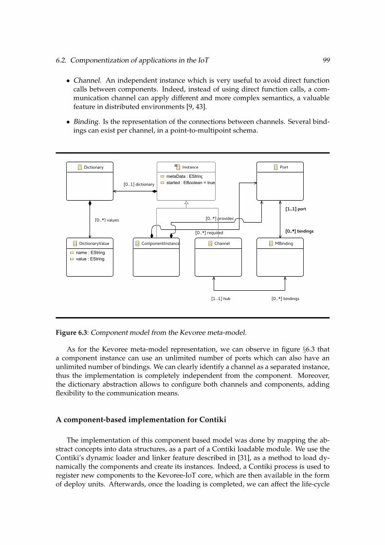
6.2. Componentization of applications in the IoT 99
• Channel. An independent instance which is very useful to avoid direct functioncalls between components. Indeed, instead of using direct function calls, a com-munication channel can apply different and more complex semantics, a valuablefeature in distributed environments [9, 43].
• Binding. Is the representation of the connections between channels. Several bind-ings can exist per channel, in a point-to-multipoint schema.
ChannelComponentInstance
Dictionary
DictionaryValue
name : EStringvalue : EString
Instance
metaData : EStringstarted : EBoolean = true
MBinding
Port
[0..1] dictionary
[0..*] provided
[0..*] required
[0..*] values
[0..*] bindings
[1..1] port
[1..1] hub [0..*] bindings
Figure 6.3: Component model from the Kevoree meta-model.
As for the Kevoree meta-model representation, we can observe in figure §6.3 thata component instance can use an unlimited number of ports which can also have anunlimited number of bindings. We can clearly identify a channel as a separated instance,thus the implementation is completely independent from the component. Moreover,the dictionary abstraction allows to configure both channels and components, addingflexibility to the communication means.
A component-based implementation for Contiki
The implementation of this component based model was done by mapping the ab-stract concepts into data structures, as a part of a Contiki loadable module. We use theContiki’s dynamic loader and linker feature described in [31], as a method to load dy-namically the components and create its instances. Indeed, a Contiki process is used toregister new components to the Kevoree-IoT core, which are then available in the formof deploy units. Afterwards, once the loading is completed, we can affect the life-cycle

100 Chapter 6. Inter-node challenges: distributing software artefacts
of the application by creating new instances of the newly downloaded type. Instancecreation is done using a simple memory block allocation scheme, allowing to create asmany instances as free memory is available.
This adaptation of the component model, even if it is very oriented to its use in aContiki environment, was optimized to achieve a behaviour very similar to the origi-nal Kevoree implementation, which is very high resource consuming. Indeed, this taskwas very challenging due to the constrained resources of the nodes on which we aim torun our experiments. Moreover, a more challenging problem raised while we tried todistribute components across the network. While using a straightforward technique toreach the target node of a component, which consisted in a direct deploy unit downloadfrom a remote repository, we realized that this method was very energy consuming. In-deed, every time a component was needed a considerable quantity of nodes in the meshnetwork were used to transport the packets to its final destination, and this was repeatedfor each node. Thus, the new challenge lies in the way a component is disseminated onthe network. Indeed, providing the best path to download it and using local ”cache”repositories to distribute a common component for several nodes could reduce energyconsumption. Therefore, a new distribution algorithm is needed in order to provide suchfunctionality. Details of this algorithm are discussed in the next section.
6.3 Calpulli: A distributed algorithm for component dissemina-tion
In this section, we present Calpulli, an algorithm designed to properly distributesoftware components in the IoT. It is then possible to provide a better component dis-tribution to the targeted nodes, thanks to the available information, both the executionstate of the system (in the M@R) and routing details of the mesh network. The goal is toreduce redundant retransmission of identical information by caching, choosing the bestnode in the network on which we can store a requested component. Thus, with the useof Calpulli, we are able to save energy while distributing components (by reducing theretransmissions). The two needed features by Calpulli are described as following:
Routing properties of the running system. Networks used by IoT systems are oftenreferred to as Low power and Lossy Networks (LLNs). The Routing Protocol RPL [111]is a IPv6 routing protocol for LLNs that builds a tree for routing, more precisely a Des-tination Oriented Directed Acyclic Graph (DODAG). This graph starts at the root/BR(Border Router), a specific node chosen by the system administrator and connected tothe rest of the wired network. Each node in the graph has a rank that represents thenumber of hops to the root. In this hierarchy, each node on the graph has a routing en-try towards its parent and it can send a data packet to the BR by forwarding it to itsimmediate parent. Figure §6.4 gives an example of a simple DODAG within a 9-nodesnetwork.

6.3. Calpulli: A distributed algorithm for component dissemination 101
Figure 6.4: Dissemination of software components using a DODAG.
Information provided by the model@runtime. The model describes all the compo-nents of all the nodes in the network. After a model synchronization, a node knowswhich components must be downloaded from the remote repository for its own adap-tation. Moreover, the information available on the model allows a wide introspectionon the current deployment, thus it is possible to know which other nodes are requestingthe same component, if any. In the example shown on Figure §6.4, the component rep-resented by the F is needed by nodes identified as 2-3-5-7-8-9. As an example, thanksto the model information, node 9 knows that the component F is requested by nodes2-3-5-7-8.
The objective of Calpulli can be summarized as follows:
• When the model has changed, the topology is used to identify how the componentswill be propagated, and where they will be cached, by parsing the model and look-ing for nodes requesting the same component (F in Figure §6.4). Once it is located,Calpulli will mark it as a temporary caching node.
• This selected node (the node 2 in our example, called the repository node) down-loads the component and acts as a local repository for other nodes (nodes 3-5-7-8-9).
• All nodes will perform the same steps, and since the model and routing informa-tion is the same all of them will select the same node as repository. Thus, they willwait for the repository node until it is ready to provide the component F.
The selection process of the repository node for the component F uses the hierarchi-cal structure of the DODAG, available in the routing information (RPL storing mode).When a node needs the component F in our example, two cases can occur:

102 Chapter 6. Inter-node challenges: distributing software artefacts
artifact location known
artifact location unknown
artifact location known
first packet download is not complete
download complete
Figure 6.5: State diagram describing a new component download, acting as a repository.
i. A node determines itself as a repository. This happens by comparing the topologyand the model, when it is found that more than 2 children need the same compo-nent. Thus, the node will wait for the children component requests.
ii. A node determines that it needs a component. If the node does not act as a repos-itory, but find that a component is needed, it will just send a component requestto its parent. Its parent, if it is not a repository, will forward the request to its ownparent, and so on until reaching the main repository, outside the local network.
Thus, when a node which was not marked as a repository receives a message from achild node asking for a component, it just forwards the message to its immediate parentwithout modification. In contrast, when the node is marked as a repository node andreceives a component request, it will store the address of the requesting node in a queue.
Calpulli can also determine that no node can be a repository candidate. Therefore,the component request will reach the Border Router, which will forward the request tothe main repository. This main repository will act as a repository node, and it will alsostore the requesting node’s addresses in a queue.
The implementation of Calpulli was integrated as a part of the Kevoree-IoT runtime,which makes use of the available UDP sockets on Contiki to transport a component froma remote repository located on the Internet. Indeed, a small protocol was developedto support Calpulli ’s downloading mechanisms, in order to establish synchronizationbetween nodes acting either as ”repositories or ”clients”. This protocol aim to use thenode address determined by Calpulli as a repository, and also to transform any nodeinto a repository if Calpulli determines it.
In Figure §6.5, a state-transition diagram is used to represent the details of the pro-posed protocol for components downloading. As we can observe, once Calpulli hasdetermined the nearest repository candidate, an artefact request is sent to such nodewhich will first determine if the artefact location is known (if the requested deploy unit
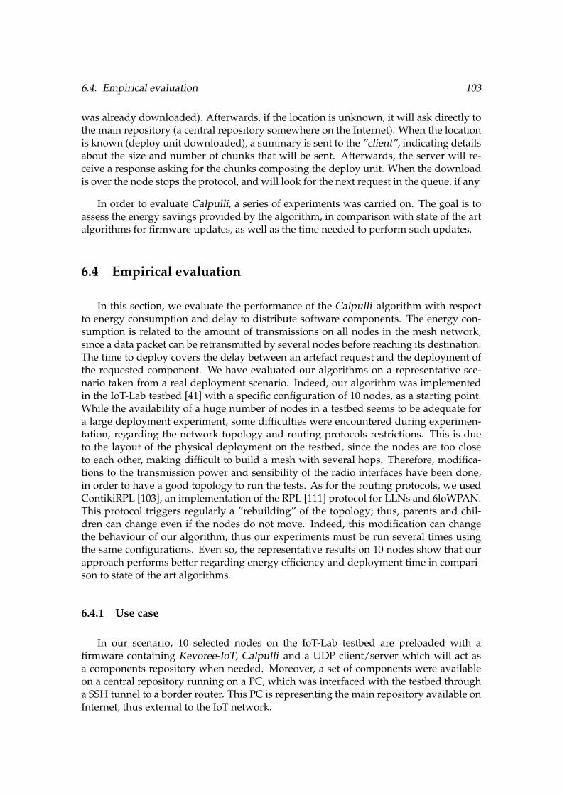
6.4. Empirical evaluation 103
was already downloaded). Afterwards, if the location is unknown, it will ask directly tothe main repository (a central repository somewhere on the Internet). When the locationis known (deploy unit downloaded), a summary is sent to the ”client”, indicating detailsabout the size and number of chunks that will be sent. Afterwards, the server will re-ceive a response asking for the chunks composing the deploy unit. When the downloadis over the node stops the protocol, and will look for the next request in the queue, if any.
In order to evaluate Calpulli, a series of experiments was carried on. The goal is toassess the energy savings provided by the algorithm, in comparison with state of the artalgorithms for firmware updates, as well as the time needed to perform such updates.
6.4 Empirical evaluation
In this section, we evaluate the performance of the Calpulli algorithm with respectto energy consumption and delay to distribute software components. The energy con-sumption is related to the amount of transmissions on all nodes in the mesh network,since a data packet can be retransmitted by several nodes before reaching its destination.The time to deploy covers the delay between an artefact request and the deployment ofthe requested component. We have evaluated our algorithms on a representative sce-nario taken from a real deployment scenario. Indeed, our algorithm was implementedin the IoT-Lab testbed [41] with a specific configuration of 10 nodes, as a starting point.While the availability of a huge number of nodes in a testbed seems to be adequate fora large deployment experiment, some difficulties were encountered during experimen-tation, regarding the network topology and routing protocols restrictions. This is dueto the layout of the physical deployment on the testbed, since the nodes are too closeto each other, making difficult to build a mesh with several hops. Therefore, modifica-tions to the transmission power and sensibility of the radio interfaces have been done,in order to have a good topology to run the tests. As for the routing protocols, we usedContikiRPL [103], an implementation of the RPL [111] protocol for LLNs and 6loWPAN.This protocol triggers regularly a ”rebuilding” of the topology; thus, parents and chil-dren can change even if the nodes do not move. Indeed, this modification can changethe behaviour of our algorithm, thus our experiments must be run several times usingthe same configurations. Even so, the representative results on 10 nodes show that ourapproach performs better regarding energy efficiency and deployment time in compari-son to state of the art algorithms.
6.4.1 Use case
In our scenario, 10 selected nodes on the IoT-Lab testbed are preloaded with afirmware containing Kevoree-IoT, Calpulli and a UDP client/server which will act asa components repository when needed. Moreover, a set of components were availableon a central repository running on a PC, which was interfaced with the testbed througha SSH tunnel to a border router. This PC is representing the main repository available onInternet, thus external to the IoT network.

104 Chapter 6. Inter-node challenges: distributing software artefacts
Our goal for this use case is to answer the following research questions:
RQ1 : Does Calpulli, our dedicated software components distribution algorithm, con-sumes less energy in average than state of the art algorithms for firmware/componentsdistribution?
RQ2 : Is Calpulli quicker to distribute software components than state of the art algo-rithms?
6.4.2 Experimental setup
This evaluation is based on experiments done with a set of physical nodes presentedin the previous Subsection. All the experiments described in this section have been car-ried out on the IoT-Lab testbed [41]. Indeed, our experiments are designed to fit a ”class2” sized node, which is called ”IoT-lab M3” on this platform. The choice of this node isdone based on precedent analysis of performance in different nodes [101], providing thebest trade-off between overall energy consumption and hardware capabilities.
In this evaluation, we consider two base line algorithms to compare our results:
• Deluge: Already described in Section §3.4.1, it is an epidemic dissemination pro-tocol [60] which aims to distribute a ”large data object” (i.e. larger that cannot fitinto node’s RAM) on WSNs. To manage the data size, an object is divided intoelementary pages. A page is the basic unit of dissemination process and allows in-cremental upgrades. This protocol guarantees the distribution of exactly the samefile to all nodes.
• Kevoree: the straightforward protocol used by the Kevoree framework [43] in theJava implementation which is agnostic of the network topology. This algorithmconsiders each node independently and each node will separately download thesoftware components which should be installed from the main repository on Inter-net.
In the two algorithms, a node will use all necessary hops to reach the main repository,contributing to the overall energy consumption during the adaptation step.
For our evaluation, we are interested in these two different variables:
• Energy consumption. It is measured using the tools provided by IoT-Lab. Thepower used by each node is sampled every 100ms, thanks to a dedicated chip(INA226 current/power monitor) installed on the control board of every node. Fora node’s power consumption, the instantaneous power Pi is sampled by the control

6.4. Empirical evaluation 105
node n times for a given time ti. Thus, the total consumption in the interval [t0, tn]is given by the following equation:
n-1X
i=0
✓(ti+1 - ti)
Pi+1 + Pi2
◆(6.1)
then a mean value for all nodes is calculated to obtain the overall consumption forthat experiment.
• deployment time. It is considered in the same way as the energy consumption,from the beginning of the adaptations until the system is executing all the compo-nent instances described on the new model.
Our experiments consider a fixed number of nodes, but the network topology variesbetween each experiment. Moreover, we also vary the number of components to dis-tribute, in order to evaluate the impact of this variable on the three algorithms (Deluge,Kevoree and Calpulli). We developed four different components, compiled as ContikiELF modules as described in §6.2.
As the topology of the RPL tree (DODAG) is hard to control within the IoT-Labtestbed, we have repeated each experiment 5 times to reduce any bias introduced bythe random topology. For all the experiments concerning Calpulli and the Kevoree al-gorithm, we have generated 10 different models (configuration including which com-ponent has to be installed on which node) for a given number of components (1 to 10).Thus, in the models, the quantity of components will be distributed among the 10 repre-sented nodes, choosing randomly one of the four available on the modelled repository.Moreover, the nodes where the components are distributed have been chosen randomlyto reduce any bias in the experiment. A total of 100 models were generated for the ex-periments
As for Deluge, a simple Contiki ELF file was produced to represent a component tobe disseminated in some selected nodes, using the implementation already available inContiki. Since Deluge does not offer any guidance for the deployment, we selected andconfigure the same ten nodes to receive the disseminated ELF file. A sink node was alsoconfigured to provide the ELF files, acting as a main repository. Indeed, we decidedto use a node as a repository, since a UDP server cannot be accessed by deluge, unlessthe server is also running Deluge. Since Deluge is not intended to run on big machines,where our UDP server is running, the best way to provide the components is to configurea single node as a repository.
The next Subsection will discuss the power needed to deploy artefacts using the de-scribed protocols.
6.4.3 Evaluation of power consumption
For our first test, we evaluated Deluge. When we tried to disseminate only one com-ponent to only one node, the protocol was very slow, exceeding the time given to our
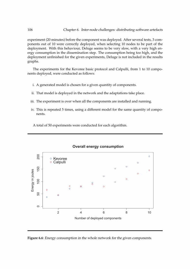
106 Chapter 6. Inter-node challenges: distributing software artefacts
experiment (20 minutes) before the component was deployed. After several tests, 3 com-ponents out of 10 were correctly deployed, when selecting 10 nodes to be part of thedeployment. With this behaviour, Deluge seems to be very slow, with a very high en-ergy consumption in the dissemination step. The consumption being too high, and thedeployment unfinished for the given experiments, Deluge is not included in the resultsgraphs.
The experiments for the Kevoree basic protocol and Calpulli, from 1 to 10 compo-nents deployed, were conducted as follows:
i. A generated model is chosen for a given quantity of components.
ii. That model is deployed in the network and the adaptations take place.
iii. The experiment is over when all the components are installed and running.
iv. This is repeated 5 times, using a different model for the same quantity of compo-nents.
A total of 50 experiments were conducted for each algorithm.
2 4 6 8 10
050
100
150
200
Overall energy consumption
Number of deployed components
Ene
rgy
in jo
ules
KevoreeCalpulli
Figure 6.6: Energy consumption in the whole network for the given components.

6.4. Empirical evaluation 107
The results of these experiments can be observed in Figure §6.6, where we acknowl-edge a reduction in the overall consumption when more than 5 components are de-ployed. Indeed, differences around 50 joules can be highlighted.
2 4 6 8 10
050
100
150
Overall time to deploy
Number of deployed components
Tim
e in
sec
onds
KevoreeCalpulli
Figure 6.7: Time to deploy the selected components.
6.4.4 Evaluation of deployment time
The time to deploy was also evaluated as a part of a trade-off given by the delay of theanalysed protocols. In the case of Deluge, as we already state in the previous evaluation,the time to deploy is too high, having only 3 nodes out of 10 working correctly, after the20 minutes given to the experiment. For the Kevoree and Calpulli algorithms, we canobserve in Figure §6.7 that the time is approximately the same for 2 and 4 components.After the fifth component, the time to deploy begins to increase. Since Calpulli has adelay in time before downloading the components, caused by the time used to resolvewhether it is a repository or not, there is a trade-off between this and the gain in energyconsumption. We argue that for larger networks the benefits could be more considerable.We discuss this on the next Section.

108 Chapter 6. Inter-node challenges: distributing software artefacts
6.5 Theoretical evaluation
After an empirical evaluation of Calpulli, we needed to know if the tendency towardsa better performance in energy consumption still there in bigger networks than 10 nodes,the subject of our first evaluation. However, the conducted experiments to get our firstresults needed a special configuration and set of nodes in order to create a stable RPLnetwork. This is very time consuming while scaling our approach for more nodes, be-sides the technical challenges when larger models need to be parsed by the constrainednodes. Indeed, even if the M3 node is able to de-serialize big models, the implementa-tion of the current model parser needs to be enhanced, which is a different challenge outof the scope of our main scientific problem. Therefore, this section proposes a theoreticalevaluation based on a very simple model of content caching, which is the main purposeof Calpulli. The goal is to assess the gain in energy by avoiding retransmissions, whichis the most energy consuming task.
0 10 20 30 40 50 60 70
distance in meters
0
5
10
15
20
25
30
dis
tan
ce in
mete
rs
Figure 6.8: Topology of the IoT-Lab M3 nodes at the Grenoble site.
6.5.1 Model of the IoT network
One of the big challenges while evaluating Calpulli, was to build a representativeRPL network by selecting the right nodes depending on the distance and the place ofthe Border Router. In this theoretical evaluation, we propose a model of the existingtopology of the Grenoble IoT-Lab testbed†1, which is presented on figure §6.8. This modelwill take into account all the M3 nodes present on the testbed represented by each blue
†1https://www.iot-lab.info/wp-content/uploads/2013/10/planMontbonnot.png
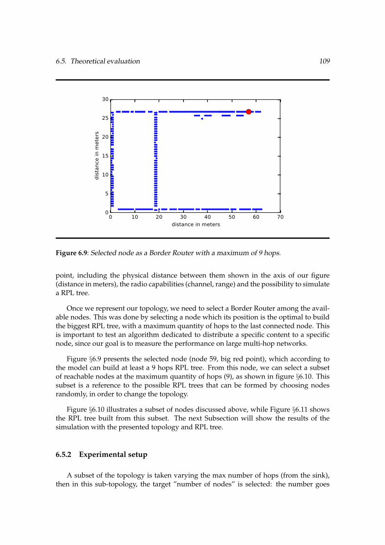
6.5. Theoretical evaluation 109
0 10 20 30 40 50 60 70
distance in meters
0
5
10
15
20
25
30d
ista
nce
in
mete
rs
Figure 6.9: Selected node as a Border Router with a maximum of 9 hops.
point, including the physical distance between them shown in the axis of our figure(distance in meters), the radio capabilities (channel, range) and the possibility to simulatea RPL tree.
Once we represent our topology, we need to select a Border Router among the avail-able nodes. This was done by selecting a node which its position is the optimal to buildthe biggest RPL tree, with a maximum quantity of hops to the last connected node. Thisis important to test an algorithm dedicated to distribute a specific content to a specificnode, since our goal is to measure the performance on large multi-hop networks.
Figure §6.9 presents the selected node (node 59, big red point), which according tothe model can build at least a 9 hops RPL tree. From this node, we can select a subsetof reachable nodes at the maximum quantity of hops (9), as shown in figure §6.10. Thissubset is a reference to the possible RPL trees that can be formed by choosing nodesrandomly, in order to change the topology.
Figure §6.10 illustrates a subset of nodes discussed above, while Figure §6.11 showsthe RPL tree built from this subset. The next Subsection will show the results of thesimulation with the presented topology and RPL tree.
6.5.2 Experimental setup
A subset of the topology is taken varying the max number of hops (from the sink),then in this sub-topology, the target ”number of nodes” is selected: the number goes

110 Chapter 6. Inter-node challenges: distributing software artefacts
0 10 20 30 40 50 60 70
distance in meters
5
10
15
20
25
30d
ista
nce
in
mete
rs
Figure 6.10: Subset of reachable nodes from the sink.
0 10 20 30 40 50 60 70
distance in meters
5
10
15
20
25
30
dis
tan
ce in
mete
rs
Figure 6.11: Theoretical RPL tree.
from 10 to the max number. For each such number of nodes 100 experiments are runwhere that number of nodes are selected randomly in the sub-topology (for example thesub-topology on figure §6.10). For each experiment, the cost of unicast and the cost with

6.5. Theoretical evaluation 111
0 50 100 150 200 250
number of nodes
0
50
100
150
200
250
300
350
400to
tal co
st (
#n
b t
ran
smis
sion
s)
unicast (max 5 hops)
caching (max 5 hops)
Figure 6.12: Number of retransmissions for 5 hops maximum.
caching are computed (= the number of necessary transmissions) with all nodes tryingto get same identical content. The distributed content is only one component, which isspread randomly between half of all available nodes. It means that every node has a 50%chances to deploy a component, which allows an approximatively binary distribution ofthe content. Disconnected nodes are not considered.
6.5.3 Evaluation results
Once our experimental setup is ready, the measurements while distributing a com-ponent on the previously modelled network took place.
Figure §6.12 shows how the cost of unicasting the component from a single sourcegrows linearly, since the needed retransmissions will grow as the hops increase. Indeed,the blue curve shows how the nodes need to retransmit a packet to the last possiblehop every time the content (a component) is requested. For instance, at the end of thecurve we can observe that we can reach around 210 nodes while limiting our tree to5 hops. Then, the cost to send the content to half of the nodes grows to around 370transmissions. The variations are due to the fact that several nodes could be attached tothe same parent, so the retransmission takes place only once per node, according to thechance of deploying such component. Another example showing the same behaviour isshown in figure §6.13
In contrast, using a simple caching technique, a node can store the content to retrans-mit it without requesting it again to the source. Indeed, less transmissions are necessary

112 Chapter 6. Inter-node challenges: distributing software artefacts
0 50 100 150 200 250 300 350
number of nodes
0
100
200
300
400
500
600
700
800
900to
tal co
st (
#n
b t
ran
smis
sion
s)
unicast (max 10 hops)
calpulli (max 10 hops)
Figure 6.13: Number of retransmissions for 10 hops maximum.
to distribute the content to all concerned nodes, since each node which is storing thecontent can distribute it to its children. We can observe that the number of transmissionsis drastically reduced by using this method, and even more for a bigger network as thepresented in figure §6.13.
With a view to give a deeper analysis, we can measure the average cost per nodewhile trying to transmit a component. This is done by taking the number of retransmis-sions divided by the quantity of nodes, in order to get an average cost per node depend-ing on the quantity of hops. Indeed, while transmitting a component to a fixed quantityof hops and a fixed number of targets, the cost will be the division between them. Inour example, observable in figures §6.14 and §6.15, we can see that the cost tends to thehalf of hops, since the target nodes are the half of the maximum reachable nodes (around340). The cost in unicast, for instance, in a maximum of 10 hops will be near to 5, whichis the average distance in hops from the sink to the destinations. But most important, wecan observe that the cost with the simple caching technique tends to one. It means thatwhile using this technique a node needs to transmit the content only once, since it’s be-ing stored on the next hop, so no need to retransmit it again if it is requested by anothernode on the same path.
6.5.4 Conclusion
These results show that an algorithm for content caching, in our case components, isstill worth considering, since the energy savings can be huge compared to straightfor-

6.5. Theoretical evaluation 113
0 50 100 150 200 250
number of nodes
1.0
1.5
2.0
2.5
3.0
3.5
4.0
4.5avg
. co
st p
er
nod
e (
#n
b t
ran
smis
sion
/ n
b n
od
e)
unicast (max 5 hops)
caching (max 5 hops)
Figure 6.14: Average cost per node for 5 hops maximum.
0 50 100 150 200 250 300 350
number of nodes
1
2
3
4
5
6
avg
. co
st p
er
nod
e (
#n
b t
ran
smis
sion
/ n
b n
od
e)
unicast (max 10 hops)
calpulli (max 10 hops)
Figure 6.15: Average cost per node for 10 hops maximum.
ward unicast protocols. The code of this simulation is publicly available for further ref-

114 Chapter 6. Inter-node challenges: distributing software artefacts
erence†2. Indeed, Calpulli performs a very similar algorithm using the knowledge of themodel which contains the nodes requesting the same component (content). Then, sincethe topology is also known, Calpulli can determine which node is the best candidateto cache the requested component. In this theoretical experiment, we can extrapolatethe behaviour of Calpulli, which we think will perform better in large networks than 10nodes, as it was shown in our empirical evaluation, according to the results presented inthis chapter.
However, we cannot completely neglect the energy needed by a node to cache a com-ponent, which can variate according to the component’s size. Indeed, a deeper evalua-tion can be performed by also modelling the overall energy consumption of a node whiletransmitting and caching content. This evaluation will be part of our perspectives.
6.6 Conclusion
This chapter presented how Kevoree-IoT, our model@runtime implementation, canbe used to deal with the problem of software deployment and configuration in Inter-net of Things systems. The main contribution presented is Calpulli, a decentralized al-gorithm which takes advantage of model@runtime information together with the net-work topology to optimize the distribution of software components, regarding energyconsumption and deployment time. We highlight that Calpulli provides a very goodtrade-off between deployment time and energy consumption with respect to Deluge andthe classical Kevoree algorithm. Indeed, our current Kevoree-IoT implementation alongwith Calpulli, can successfully distribute software components into an IoT network inan efficient manner.
Therefore, two things can be noticed on the execution of our approach:
i. We provided a mechanism to distribute software components to specific nodes
ii. and an algorithm to efficiently distribute such components.
With these contributions, we have added adaptation features to nodes being part ofan IoT system. Indeed, each node can perform different types of adaptations and changeits behaviour regarding the execution state before a new model is disseminated in thenetwork.
Results
While evaluating Calpulli, our results show that a trade-off exists between compo-nents distribution speed and the energy consumption, resulting in overall energy sav-ings. Indeed, in the empirical evaluation Calpulli was able to save energy while caching
†2https://cloud.sagemath.com/projects/269f7823-e948-4bab-8e0b-999ae12c8685/files/TopologyAnalysis.html

6.6. Conclusion 115
content on intermediate nodes before reaching the actual concerned node. Energy sav-ing is very important in networks like the IoT, where the topology coupled with the en-ergy constraints can determine the life-cycle of a node. Moreover, our theoretical resultsshow that algorithms such Calpulli are very pertinent in networks with a huge quantityof nodes, especially on multi-hop mesh topologies.
These results are complemented by our theoretical evaluation, on which we arguethat in bigger networks, Calpulli will save even more energy, according to the numberof hops needed to reach the source of components.

116 Chapter 6. Inter-node challenges: distributing software artefacts

Part IV
Conclusions and future work


Chapter 7
Conclusions
Software engineering is a research domain that has reached a very mature statusnowadays. While its applications are intended to solve problems for very complex andlarge software systems, we have highlighted throughout this thesis some aspects that canbe leveraged for their adoption to solve problems related to software management on theInternet of Things. More specifically, Model Driven Engineering has been studied on thecontext of distributed systems, since its similarities with the IoT seem evident. Therefore,the scientific problems raised by this new paradigm are the same than those already cov-ered for distributed applications. However, the very different capacities and networktopology of IoT systems make this adoption very challenging. Indeed, we showed thatthe hardware constraints and energy autonomy typical of IoT nodes are the main obsta-cle to implement the solutions proposed by the MDE community ”as is”.
7.1 From IoT to MDE
Our state of the art described these two domains in detail, presenting at first the newparadigm of the Internet of Things and its main characteristics as a typical distributedsystem, and second the most recent tools aiming to solve a common issue found on thesetwo domains: the management of a distributed software layer for (self)adaptation pur-poses. This management is very important in complex and large systems such as the pre-sented on this thesis, since maintenance costs and services downtime can be drasticallyreduced by applying the right techniques. Indeed, the existing approaches proposedto deal with this problem have shown their capacity to increase efficiency by providingseveral tools for developers and maintainers, leveraging abstract models that can be ma-nipulated in a safer and easier way than the actual system. Moreover, dividing theselarge systems into small software components easier to maintain has been presented asan excellent complement to provide adaptation mechanisms, by facilitating their replace-ment and addition of new ones, resulting in new behaviours. Thus, these promising re-sults have been the source of inspiration to us to investigate the main principles for theiradoption on very resource constrained environments such as the IoT.
120 Chapter 7. Conclusions
7.2 Models@runtime to manipulate IoT software
Our first contribution make use of these models, known as ”models@runtime”, toprovide an abstract representation of a whole IoT network, including the running ap-plications, their current state of execution and bindings between components. The im-plementation of this approach is inspired from the Kevoree meta-model, taking into ac-count the very scarce resources found on IoT devices. We first show that the use ofmodels@runtime on IoT devices is possible, with a small overhead compared to the ben-efits of the system representation through a model. Indeed, our experiments determinedthe limits of this approach, by calculating an approximate number of maximum nodesand components that can be present on the model before exhausting the memory capac-ities of a typical IoT device. Afterwards, we highlighted the system facilities necessaryto execute the adaptations generated by a model manipulation (changes on the currentmodel). These facilities have been extended for our target IoT nodes, in order to providea complete experimentation platform which fits our requirements.
Thus far, we provided a mechanism to reflect our system in the form of amodel@runtime and synchronize the current execution state to match with its repre-sentation. In order to provide the adaptation mechanisms, a component model basedon dynamic loading of code has been implemented, relying on the possibility of the un-derlying system to actually load new code. This component model follows the sameKevoree meta-model representation, which can also be synchronized together with theIoT node and network characteristics.
We can highlight that the use of a model@runtime to manage the software layer inIoT devices is possible, and adds an abstraction layer which facilitates the distributionof tasks among different nodes on the IoT, thanks to the components decoupling of thewhole system.
7.3 Towards ”content caching” via Calpulli
Our second contribution highlights the very specific problem of components distri-bution, found in IoT environments due to the network topology. Indeed, this problem isnot present in typical distributed systems, since they rely its communication means onvery robust, fast and reliable networks. We argue that component downloading usingepidemic dissemination of components reduces the capacity to finely select the nodes tobe updated/extended, since state of the art protocols are not guided by an abstract rep-resentation of the system. In addition, individual downloading of components can useseveral nodes on a mesh topology, in order to reach the component repository. In most ofcases, these nodes are used several times to forward the same content requested by dif-ferent nodes, thus energy is wasted using this approach. Therefore, a new algorithm hasbeen proposed to deal with the high-energy consumption while transmitting softwareartefacts through a mesh network, typical of the IoT. Our approach, called Calpulli, usesthe knowledge of the network topology through a typical IoT routing protocol, RPL, cou-pled with the application information available on the model, to find the best path and
7.3. Towards ”content caching” via Calpulli 121
caching mechanisms for artefacts downloading. The evaluation of our approach showedthat even in a small representative network, the benefits of using such an algorithm areimportant regarding the energy consumption.
In summary, our algorithm for component caching results in a very efficient way todistribute software artefacts among the nodes present in an IoT network, while savinga considerable amount of energy. Moreover, this algorithm will perform better as thenetwork grows.
In overall, we can conclude that mechanisms for software management in very large,heterogeneous and non-monolithic distributed systems, as the Internet of Things, arenecessary, due to the high efforts required to maintain the life-cycle of software runningon these platforms. Moreover, we highlighted that IoT systems require specific mecha-nisms to provide such management, since the target nodes are very different to typicalnodes present in distributed systems. Indeed, the constrained resources and networkenvironment make the development of management tools very challenging. Therefore,the proposed approaches and algorithms to perform this task are the firsts steps towardsa more complete framework to support dynamic behaviour and self-adaptation on theInternet of Things, as it was presented throughout this thesis.

122 Chapter 7. Conclusions

Chapter 8
Perspectives
The presented research work has shown that software engineering tools coupled witha fine knowledge of the constraints found in IoT systems are able to enable adaptationfeatures for these large distributed systems. Indeed, several perspectives are open forfuture work. The next sections will present them in detail.
8.1 Modelling tools for accurate code generation
Our current implementation relies on a manual transformation of the Kevoree meta-model in order to provide the C code that can be compiled for the Contiki OS. Therefore,automatic tools inspired, for instance, from KMF [46], can be used to provide a flexibleframework which enables a more versatile meta-model implementation, in addition toa more accurate code generation. Moreover, using high level modelling tools can leadto optimizations on the generated code, since changes on the abstract representation areeasier to perform than manual coding.
8.2 A flexible component development framework
The programming model used to implement components for resource constraineddevices can have strong dependencies on the underlying OS. Indeed, our approach canbe extended to support high level modelling tools to provide the right code depend-ing on the chosen OS, avoiding specific development restrictions, since the componentmodel is already provided.

124 Chapter 8. Perspectives
8.3 Leverage ICN mechanisms for efficient components distri-bution
Our presented protocol, Calpulli, shares several principles that are being investigatedby the Information-Centric Networking (ICN) [4]. Indeed, this paradigm explores in-network caching, multi-party communication through replication, and interaction mod-els decoupling senders and receivers. The goal is, as for Calpulli, to provide the bestmechanisms for highly scalable and efficient distribution of content to better cope withdisconnections, disruptions, and flash crowd effects in the communication service. Inour particular case, software component distribution, these mechanisms are of high in-terest, since reductions on retransmissions of the same content lead to energy savings.It is then interesting to investigate such approach, and to explore the possibilities to useour model-based approach to improve its efficiency.

Bibliography
[1] Ieee standard for local and metropolitan area networks–part 15.4: Low-rate wire-less personal area networks (lr-wpans). IEEE Std 802.15.4-2011 (Revision of IEEEStd 802.15.4-2006), pages 1–314, Sept 2011
[2] Ieee standard for information technology–telecommunications and informationexchange between systems local and metropolitan area networks–specific require-ments part 11: Wireless lan medium access control (mac) and physical layer (phy)specifications. IEEE Std 802.11-2012 (Revision of IEEE Std 802.11-2007), pages 1–2793, March 2012
[3] Iso/iec/ieee international standard for ethernet. ISO/IEC/IEEE 8802-3:2014(E),pages 1–3754, April 2014
[4] B. Ahlgren, C. Dannewitz, C. Imbrenda, D. Kutscher, and B. Ohlman. A surveyof information-centric networking. Communications Magazine, IEEE, 50(7):26–36,2012
[5] L. Atzori, A. Iera, and G. Morabito. The internet of things: A survey. ComputerNetworks, 54(15):2787 – 2805, 2010
[6] E. Baccelli, O. Hahm, M. Gunes, M. Wahlisch, and T. Schmidt. Riot os: Towardsan os for the internet of things. In Computer Communications Workshops (INFO-COM WKSHPS), 2013 IEEE Conference on, pages 79–80, April 2013
[7] E. Bailey. Maximum rpm. red hat software. Inc., February, 1997
[8] B. Baker. The Official InstallShield for Windows Installer Developer’s Guide. M &T Books, 2001
[9] O. Barais. Construire et Maıtriser l’evolution d’une architecture logicielle a basede composants. PhD thesis, Lille 1, 2005
[10] G. Blair, N. Bencomo, and R. B. France. [email protected]. Computer, 42(10):22–27,2009
[11] C. Bormann, M. Ersue, and A. Keranen. Terminology for Constrained-Node Net-works. RFC 7228, RFC Editor, May 2014
126 Bibliography
[12] N. Brouwers, K. Langendoen, and P. Corke. Darjeeling, a feature-rich vm for the re-source poor. In Proceedings of the 7th ACM Conference on Embedded NetworkedSensor Systems, pages 169–182. ACM, 2009
[13] E. Bruneton, T. Coupaye, M. Leclercq, V. Quema, and J.-B. Stefani. The fractalcomponent model and its support in java. Software-Practice and Experience, 36(11):1257–1284, 2006
[14] A. Carzaniga. A characterization of the software deployment process and a sur-vey of related technologies. Technical report, Technischer Bericht, Dipartimento diElettronica e Informazione, Politecnico di Milano, 1997
[15] H. Cha, S. Choi, I. Jung, H. Kim, H. Shin, J. Yoo, and C. Yoon. Retos: resilient,expandable, and threaded operating system for wireless sensor networks. In In-formation Processing in Sensor Networks, 2007. IPSN 2007. 6th International Sym-posium on, pages 148–157. IEEE, 2007
[16] Y.-T. Chen, T.-C. Chien, and P. H. Chou. Enix: a lightweight dynamic operatingsystem for tightly constrained wireless sensor platforms. In Proceedings of the 8thACM Conference on Embedded Networked Sensor Systems, pages 183–196. ACM,2010
[17] D. Cid and others. Looci: The loosely-coupled component infrastructure. In 2012IEEE 11th International Symposium on Network Computing and Applications,pages 236–243, 2012
[18] T. Committee and others. Tool interface standard (tis) executable and linking for-mat (elf) specification version 1.2. TIS Committee, 1995
[19] Contiki. Contiki ip stack. https://github.com/contiki-os/contiki/tree/release-3-0, Ac-cessed: 2016-01-13
[20] G. F. Coulouris, J. Dollimore, and T. Kindberg. Distributed systems: concepts anddesign. pearson education, 2005
[21] I. Crnkovic and M. P. H. Larsson. Building reliable component-based softwaresystems. Artech House, 2002
[22] E. Damou. ApAM: un environnement pour le developpement et l’executiond’applications ubiquitaires. PhD thesis, Universite de Grenoble, 2013
[23] E. M. Dashofy, A. Van der Hoek, and R. N. Taylor. An infrastructure for the rapiddevelopment of xml-based architecture description languages. In Software En-gineering, 2002. ICSE 2002. Proceedings of the 24rd International Conference on,pages 266–276. IEEE, 2002
[24] S. Deering and R. Hinden. Internet Protocol, Version 6 (IPv6) Specification. RFC2460, RFC Editor, December 1998
[25] C. B. Des Rosiers, G. Chelius, E. Fleury, A. Fraboulet, A. Gallais, N. Mitton, andT. Noel. Senslab very large scale open wireless sensor network testbed. In Proc.
Bibliography 127
7th International ICST Conference on Testbeds and Research Infrastructures forthe Development of Networks and Communities (TridentCOM), 2011
[26] W. Dong, C. Chen, X. Liu, J. Bu, and Y. Liu. Dynamic linking and loading in net-worked embedded systems. In Mobile Adhoc and Sensor Systems, 2009. MASS’09.IEEE 6th International Conference on, pages 554–562. IEEE, 2009
[27] A. Dunkels. Full TCP/IP for 8 Bit Architectures. In Proceedings of the FirstACM/Usenix International Conference on Mobile Systems, Applications and Ser-vices (MobiSys 2003), San Francisco, May 2003. USENIX.
[28] A. Dunkels. A low-overhead script language for tiny networked embedded sys-tems. SICS Research Report, 2006
[29] A. Dunkels. Rime—a lightweight layered communication stack for sensor net-works. In Proceedings of the European Conference on Wireless Sensor Networks(EWSN), Poster/Demo session, Delft, The Netherlands. Citeseer, 2007
[30] A. Dunkels. The contikimac radio duty cycling protocol. Technical report, 2011
[31] A. Dunkels, N. Finne, J. Eriksson, and T. Voigt. Run-time dynamic linking forreprogramming wireless sensor networks. In Proceedings of the 4th InternationalConference on Embedded Networked Sensor Systems, SenSys ’06, pages 15–28,New York, NY, USA, 2006. ACM
[32] A. Dunkels, B. Gronvall, and T. Voigt. Contiki-a lightweight and flexible operat-ing system for tiny networked sensors. In Local Computer Networks, 2004. 29thAnnual IEEE International Conference on, pages 455–462. IEEE, 2004
[33] A. Dunkels, O. Schmidt, T. Voigt, and M. Ali. Protothreads: simplifying event-driven programming of memory-constrained embedded systems. In Proceedingsof the 4th international conference on Embedded networked sensor systems, pages29–42. Acm, 2006
[34] S. Duquennoy, G. Grimaud, and J.-J. Vandewalle. The web of things: Intercon-necting devices with high usability and performance. In Embedded Software andSystems, 2009. ICESS ’09. International Conference on, pages 323–330, May 2009
[35] M. Durvy, J. Abeille, P. Wetterwald, C. O’Flynn, B. Leverett, E. Gnoske, M. Vidales,G. Mulligan, N. Tsiftes, N. Finne, and A. Dunkels. Making sensor networks ipv6ready. In Proceedings of the Sixth ACM Conference on Networked EmbeddedSensor Systems (ACM SenSys 2008), poster session, Raleigh, North Carolina, USA,November 2008.
[36] J. Estublier and G. Vega. Managing mutiple applications in a service platform. InPrinciples of Engineering Service Oriented Systems (PESOS), 2012 ICSE Workshopon, pages 36–42. IEEE, 2012
[37] J. Estublier, G. Vega, and E. Damou. Resource management for pervasive systems.In Service-Oriented Computing-ICSOC 2012 Workshops, pages 368–379. Springer,2013
128 Bibliography
[38] H. Farhangi. The path of the smart grid. Power and Energy Magazine, IEEE, 8(1):18–28, 2010
[39] R. Fielding, J. Gettys, J. Mogul, H. Frystyk, L. Masinter, P. Leach, and T. Berners-Lee. Hypertext Transfer Protocol – HTTP/1.1. RFC 2616, RFC Editor, June 1999
[40] R. T. Fielding and R. N. Taylor. Principled design of the modern web architecture.ACM Trans. Internet Technol., 2(2):115–150, May 2002
[41] E. Fleury, N. Mitton, T. Noel, C. Adjih, V. Loscri, A. M. Vegni, R. Petrolo, V. Lo-scri, N. Mitton, G. Aloi, and others. Fit iot-lab: The largest iot open experimentaltestbed. ERCIM News, 2015(101), 2015
[42] T. R. Foundation. The raspberry pi. https://www.raspberrypi.org/help/what-is-a-raspberry-pi, Accessed: 2015-08-26
[43] F. Fouquet. Kevoree: Model@ Runtime pour le developpement continu desystemes adaptatifs distribues heterogenes. PhD thesis, Universite de Rennes 1,2013
[44] F. Fouquet, E. Daubert, N. Plouzeau, O. Barais, J. Bourcier, and J.-M. Jezequel. Dis-semination of reconfiguration policies on mesh networks. In Distributed Applica-tions and Interoperable Systems, pages 16–30. Springer, 2012
[45] F. Fouquet, B. Morin, F. Fleurey, O. Barais, N. Plouzeau, and J.-M. Jezequel. Adynamic component model for cyber physical systems. In Proceedings of the 15thACM SIGSOFT symposium on Component Based Software Engineering, pages135–144. ACM, 2012
[46] F. Fouquet, G. Nain, B. Morin, E. Daubert, O. Barais, N. Plouzeau, and J.-M.Jezequel. An eclipse modelling framework alternative to meet the models@ run-time requirements. Springer, 2012
[47] FP7-ICT-2009-5-257992. Project smartsantander. http://www.smartsantander.eu,Accessed: 2015-09-06
[48] L. F. Friedrich, J. Stankovic, M. Humphrey, M. Marley, and J. Haskins. A surveyof configurable, component-based operating systems for embedded applications.Ieee micro, (3):54–68, 2001
[49] P. Goldsack, J. Guijarro, A. Lain, G. Mecheneau, P. Murray, and P. Toft. Smartfrog:Configuration and automatic ignition of distributed applications. HP OVUA, 2003
[50] P. Grace, G. Coulson, G. Blair, L. Mathy, W. K. Yeung, W. Cai, D. Duce, andC. Cooper. Gridkit: Pluggable overlay networks for grid computing. In On theMove to Meaningful Internet Systems 2004: CoopIS, DOA, and ODBASE, pages1463–1481. Springer, 2004
[51] E. Grassl and F. Schmidt. Energy-autonomous electromechanical wireless switch,March 28 2006.

Bibliography 129
[52] O. N. Gunalp. Continuous deployment of pervasive applications in dynamic en-vironments. PhD thesis, Universite Grenoble Alpes, 2014
[53] O. Hahm, E. Baccelli, H. Petersen, and N. Tsiftes. Operating systems for low-enddevices in the internet of things: a survey. Internet of Things Journal, IEEE, PP(99):1–1, 2015
[54] O. Hahm. Riot os. http://riot-os.org/files/RIOT.pdf, 2014
[55] R. S. Hall, D. Heimbigner, and A. L. Wolf. A cooperative approach to support soft-ware deployment using the software dock. In Proceedings of the 21st internationalconference on Software engineering, pages 174–183. ACM, 1999
[56] C.-C. Han, R. Kumar, R. Shea, E. Kohler, and M. Srivastava. A dynamic operatingsystem for sensor nodes. In Proceedings of the 3rd international conference onMobile systems, applications, and services, pages 163–176. ACM, 2005
[57] T. Hartmann, F. Fouquet, J. Klein, Y. Le Traon, A. Pelov, L. Toutain, and T. Ropitault.Generating realistic smart grid communication topologies based on real-data. InSmart Grid Communications (SmartGridComm), 2014 IEEE International Confer-ence on, pages 428–433, Nov 2014
[58] G. T. Heineman and W. T. Councill, editors. Component-based Software Engineer-ing: Putting the Pieces Together. Addison-Wesley Longman Publishing Co., Inc.,Boston, MA, USA, 2001
[59] HiKoB. M3 open node. https://www.iot-lab.info/hardware/m3/, Accessed: 2015-08-26
[60] J. W. Hui and D. Culler. The dynamic behavior of a data dissemination protocol fornetwork programming at scale. In Proceedings of the 2nd international conferenceon Embedded networked sensor systems, pages 81–94. ACM, 2004
[61] J. Jeong and D. Culler. Incremental network programming for wireless sensors. InSensor and Ad Hoc Communications and Networks, 2004. IEEE SECON 2004. 2004First Annual IEEE Communications Society Conference on, pages 25–33. IEEE,2004
[62] M. Jung, J. Weidinger, W. Kastner, and A. Olivieri. Building automation andsmart cities: An integration approach based on a service-oriented architecture. InAdvanced Information Networking and Applications Workshops (WAINA), 201327th International Conference on, pages 1361–1367, March 2013
[63] W. Kastner, G. Neugschwandtner, S. Soucek, and H. Newmann. Communicationsystems for building automation and control. Proceedings of the IEEE, 93(6):1178–1203, June 2005
[64] M. Kelly. Gain control of application setup and maintenance with the new win-dows installer-the new windows installer does more than just copy files; it letsyour windows 95, windows 98, or windows nt. Microsoft Systems Journal-USEdition, pages 15–28, 1998

130 Bibliography
[65] A. G. Kleppe, J. B. Warmer, and W. Bast. MDA explained: the model driven archi-tecture: practice and promise. Addison-Wesley Professional, 2003
[66] J. Ko, K. Klues, C. Richter, W. Hofer, B. Kusy, M. Bruenig, T. Schmid, Q. Wang,P. Dutta, and A. Terzis. Low power or high performance? a tradeoff whose timehas come (and nearly gone). In Wireless Sensor Networks, pages 98–114. Springer,2012
[67] G. Kortuem, F. Kawsar, D. Fitton, and V. Sundramoorthy. Smart objects as buildingblocks for the internet of things. Internet Computing, IEEE, 14(1):44–51, 2010
[68] M. Kovatsch, M. Lanter, and S. Duquennoy. Actinium: A restful runtime containerfor scriptable internet of things applications. In Internet of Things (IOT), 2012 3rdInternational Conference on the, pages 135–142. IEEE, 2012
[69] J. Kramer and J. Magee. The evolving philosophers problem: Dynamic changemanagement. Software Engineering, IEEE Transactions on, 16(11):1293–1306, 1990
[70] B. Len, C. Paul, and K. Rick. Software architecture in practice. Boston, Mas-sachusetts Addison, 2003
[71] P. Levis and D. Culler. Mate: A tiny virtual machine for sensor networks. In ACMSigplan Notices, volume 37, pages 85–95. ACM, 2002
[72] P. Levis, S. Madden, J. Polastre, R. Szewczyk, K. Whitehouse, A. Woo, D. Gay,J. Hill, M. Welsh, E. Brewer, and others. Tinyos: An operating system for sensornetworks. In Ambient intelligence, pages 115–148. Springer, 2005
[73] P. J. Marron, M. Gauger, A. Lachenmann, D. Minder, O. Saukh, and K. Rothermel.Flexcup: A flexible and efficient code update mechanism for sensor networks. InWireless Sensor Networks, pages 212–227. Springer, 2006
[74] P. K. McKinley, S. M. Sadjadi, E. P. Kasten, and B. H. Cheng. Composing adaptivesoftware. Computer, (7):56–64, 2004
[75] N. Medvidovic and R. N. Taylor. A classification and comparison framework forsoftware architecture description languages. Software Engineering, IEEE Transac-tions on, 26(1):70–93, 2000
[76] G. Montenegro, N. Kushalnagar, J. Hui, and D. Culler. Transmission of IPv6 Pack-ets over IEEE 802.15.4 Networks. RFC 4944, RFC Editor, September 2007
[77] B. Morin. Leveraging Models from Design-time to Runtime to Support DynamicVariability. PhD thesis, Universite de Rennes 1, 2010
[78] B. Morin, O. Barais, J.-M. Jezequel, F. Fleurey, and A. Solberg. Models@ Run.timeto Support Dynamic Adaptation. Computer, 42(10):44–51, 2009
[79] B. Morin, O. Barais, G. Nain, and J.-M. Jezequel. Taming dynamically adaptivesystems using models and aspects. In Proceedings of the 31st International Con-ference on Software Engineering, pages 122–132. IEEE Computer Society, 2009

Bibliography 131
[80] L. Mottola, G. P. Picco, and A. A. Sheikh. Figaro: Fine-grained software reconfigu-ration for wireless sensor networks. In Wireless Sensor Networks, pages 286–304.Springer, 2008
[81] I. Murdock. Overview of the debian gnu/linux system. Linux Journal, 1994(6es):15, 1994
[82] G. Nain, E. Daubert, O. Barais, and J.-M. Jezequel. Using mde to build aschizophrenic middleware for home/building automation. Springer, 2008
[83] M. Neugschwandtner, G. Neugschwandtner, and W. Kastner. Web services inbuilding automation: Mapping knx to obix. In Industrial Informatics, 2007 5thIEEE International Conference on, volume 1, pages 87–92, June 2007
[84] R. Oliver, A. Wilde, and E. Zaluska. Reprogramming embedded systems at run-time. In Proceedings of the 8th International Conference on Sensing Technology,pages 124–129. IEEE Instrumentation and Measurement Society, 2014
[85] P. Oreizy, M. M. Gorlick, R. N. Taylor, D. Heimbigner, G. Johnson, N. Medvidovic,A. Quilici, D. S. Rosenblum, and A. L. Wolf. An architecture-based approach toself-adaptive software. IEEE Intelligent systems, (3):54–62, 1999
[86] A. Paepcke. Object-oriented programming: the CLOS perspective. MIT press, 1993
[87] L. Perez-Lombard, J. Ortiz, and C. Pout. A review on buildings energy consump-tion information. Energy and buildings, 40(3):394–398, 2008
[88] N. Reijers and K. Langendoen. Efficient code distribution in wireless sensor net-works. In Proceedings of the 2nd ACM international conference on Wireless sensornetworks and applications, pages 60–67. ACM, 2003
[89] R. Rouvoy, P. Barone, Y. Ding, F. Eliassen, S. Hallsteinsen, J. Lorenzo, A. Mamelli,and U. Scholz. Music: Middleware support for self-adaptation in ubiquitous andservice-oriented environments. In Software engineering for self-adaptive systems,pages 164–182. Springer, 2009
[90] M. Sarwar and T. R. Soomro. Impact of smartphone’s on society. European Journalof Scientific Research, 98(2):216–226, 2013
[91] Z. Shelby, K. Hartke, and C. Bormann. The Constrained Application Protocol(CoAP). RFC 7252, RFC Editor, June 2014
[92] Z. Shelby. Embedded web services. Wireless Commun., 17(6):52–57, December2010
[93] G. N. Silva. Apt howto, 2001
[94] O. A. Specification. Deployment and configuration of component-based dis-tributed applications specification, 2006
[95] S. Stolberg. Enabling agile testing through continuous integration. In Agile Con-ference, 2009. AGILE’09., pages 369–374. IEEE, 2009

132 Bibliography
[96] C. Szyperski. Component Software: Beyond Object-Oriented Programming.Addison-Wesley Longman Publishing Co., Inc., Boston, MA, USA, edition 2nd,2002
[97] C. Szyperski. Component technology: what, where, and how? In Proceedingsof the 25th international conference on Software engineering, pages 684–693. IEEEComputer Society, 2003
[98] A. Taherkordi, F. Loiret, R. Rouvoy, and F. Eliassen. Optimizing sensor network re-programming via in situ reconfigurable components. ACM Transactions on SensorNetworks (TOSN), 9(2):14, 2013
[99] V. Talwar, D. Milojicic, Q. Wu, C. Pu, W. Yan, and G.-P. Jung. Approaches forservice deployment. Internet Computing, IEEE, 9(2):70–80, 2005
[100] R. N. Taylor, N. Medvidovic, and P. Oreizy. Architectural styles for runtime soft-ware adaptation. In Software Architecture, 2009 & European Conference on Soft-ware Architecture. WICSA/ECSA 2009. Joint Working IEEE/IFIP Conference on,pages 171–180. IEEE, 2009
[101] I. Tsekoura, G. Rebel, P. Glosekotter, and M. Berekovic. An evaluation of energy ef-ficient microcontrollers. In Reconfigurable and Communication-Centric Systems-on-Chip (ReCoSoC), 2014 9th International Symposium on, pages 1–5. IEEE, 2014
[102] N. Tsiftes, A. Dunkels, Z. He, and T. Voigt. Enabling large-scale storage in sensornetworks with the coffee file system. In Proceedings of the 8th ACM/IEEE Inter-national Conference on Information Processing in Sensor Networks (IPSN 2009),San Francisco, USA, April 2009
[103] N. Tsiftes, J. Eriksson, and A. Dunkels. Low-power wireless ipv6 routing withcontikirpl. In Proceedings of the 9th ACM/IEEE International Conference on In-formation Processing in Sensor Networks, IPSN ’10, pages 406–407, New York, NY,USA, 2010. ACM
[104] J. Turnbull. The Docker Book: Containerization is the new virtualization. JamesTurnbull, 2014
[105] A. Van Moorsel. Metrics for the internet age: Quality of experience and qualityof business. In Fifth International Workshop on Performability Modeling of Com-puter and Communication Systems, Arbeitsberichte des Instituts fur Informatik,Universitat Erlangen-Nurnberg, Germany, volume 34, pages 26–31. Citeseer, 2001
[106] R. Van Ommering, F. Van Der Linden, J. Kramer, and J. Magee. The koala compo-nent model for consumer electronics software. Computer, 33(3):78–85, 2000
[107] S. Vidal and J. Antill. Upgrade and downgrade in package update operations,August 12 2014.
[108] J.-B. Waldner and J. B. Waldner. Nano-informatique et intelligence ambiante: in-venter l’ordinateur du XXIe siecle. Hermes Science, 2007
Bibliography 133
[109] X. Wang, W. Li, H. Liu, and Z. Xu. A language-based approach to service deploy-ment. In Services Computing, 2006. SCC’06. IEEE International Conference on,pages 69–76. IEEE, 2006
[110] M. Weiser. The computer for the 21st century. SIGMOBILE Mob. Comput. Com-mun. Rev., 3(3):3–11, July 1999
[111] E. Winter, T., E. Thubert, P., A. Brandt, J. Hui, R. Kelsey, P. Levis, K. Pister, R. Struik,J. Vasseur, and R. Alexander. RPL: IPv6 Routing Protocol for Low-Power and LossyNetworks. RFC 6550, RFC Editor, March 2012
[112] B. Woolf and R. Johnson. The type object pattern. Pattern Languages of ProgramDesign, 3:132, 1996
[113] M. Younis and K. Akkaya. Strategies and techniques for node placement in wire-less sensor networks: A survey. Ad Hoc Networks, 6(4):621 – 655, 2008
[114] J. Zhang and B. H. Cheng. Model-based development of dynamically adaptivesoftware. In Proceedings of the 28th international conference on Software engi-neering, pages 371–380. ACM, 2006

134 Bibliography
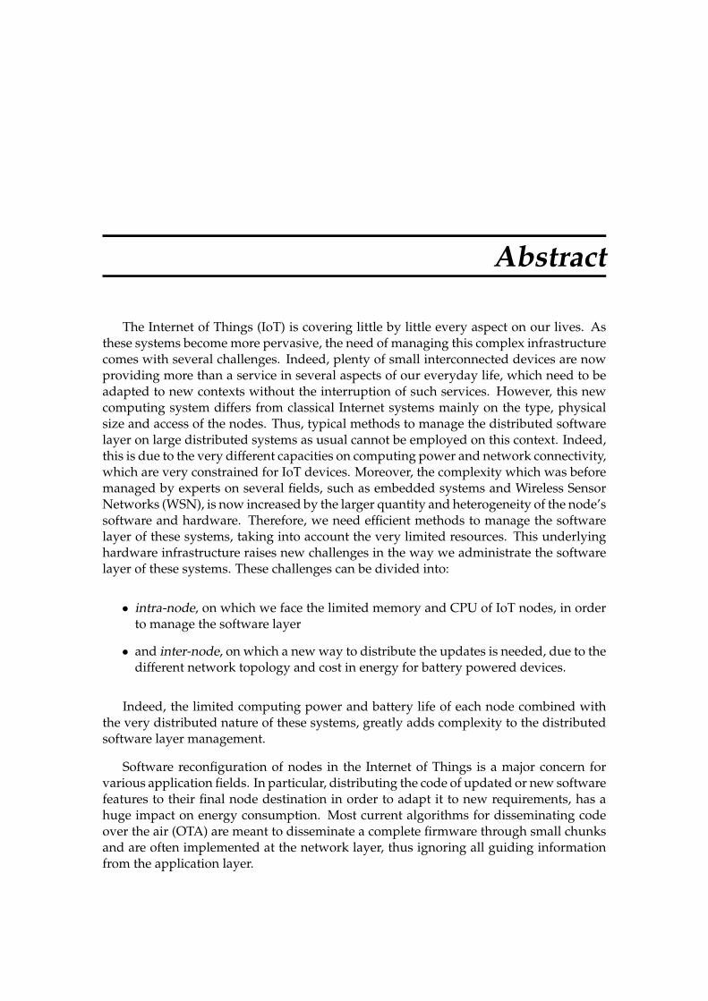
Abstract
The Internet of Things (IoT) is covering little by little every aspect on our lives. Asthese systems become more pervasive, the need of managing this complex infrastructurecomes with several challenges. Indeed, plenty of small interconnected devices are nowproviding more than a service in several aspects of our everyday life, which need to beadapted to new contexts without the interruption of such services. However, this newcomputing system differs from classical Internet systems mainly on the type, physicalsize and access of the nodes. Thus, typical methods to manage the distributed softwarelayer on large distributed systems as usual cannot be employed on this context. Indeed,this is due to the very different capacities on computing power and network connectivity,which are very constrained for IoT devices. Moreover, the complexity which was beforemanaged by experts on several fields, such as embedded systems and Wireless SensorNetworks (WSN), is now increased by the larger quantity and heterogeneity of the node’ssoftware and hardware. Therefore, we need efficient methods to manage the softwarelayer of these systems, taking into account the very limited resources. This underlyinghardware infrastructure raises new challenges in the way we administrate the softwarelayer of these systems. These challenges can be divided into:
• intra-node, on which we face the limited memory and CPU of IoT nodes, in orderto manage the software layer
• and inter-node, on which a new way to distribute the updates is needed, due to thedifferent network topology and cost in energy for battery powered devices.
Indeed, the limited computing power and battery life of each node combined withthe very distributed nature of these systems, greatly adds complexity to the distributedsoftware layer management.
Software reconfiguration of nodes in the Internet of Things is a major concern forvarious application fields. In particular, distributing the code of updated or new softwarefeatures to their final node destination in order to adapt it to new requirements, has ahuge impact on energy consumption. Most current algorithms for disseminating codeover the air (OTA) are meant to disseminate a complete firmware through small chunksand are often implemented at the network layer, thus ignoring all guiding informationfrom the application layer.

136 Abstract
Contribution 1: A new middleware to manage IoT Software Up-dates (SU)
In this thesis, we first propose a design of a new middleware dedicated to IoT devicesto enable the management of software deployment and the dynamic reconfiguration ofthese systems, by updating its original firmware. This middleware will act as an ab-straction layer, inspired from the Models@Runtime paradigm coupled with ComponentBased Software Engineering (CBSE), in order to manage the inherent adaptive behaviourof an IoT system. This new design will take into account the very constrained nature ofthe nodes being part of the IoT, which was not addressed by previous implementationsof models@runtime and CBSE. It includes the manual transformation into C code of amodels@runtime meta-model, which represents both the network and the applicationlayer of the Internet of Things systems, which would be part of each device’s firmware.Moreover, a new implementation is provided and an evaluation on a typical IoT in-frastructure demonstrates the feasibility of providing a model@runtime middleware forthese systems, addressing what we called the intra-node challenges. Thus, distribu-tion, instantiation and (re)configuration of the software layer, now decoupled into smallpieces represented by software components, is facilitated through the abstraction layer,which can be manipulated before its actual execution on the real system.
Contribution 2: A new algorithm to distribute SU in IoT net-works
In our second contribution, we address the inter-node challenges. At runtime, weleverage the model@runtime coupled with the network information (obtained from therouting protocol) through a new algorithm to distribute software components only tothose devices that need it, while adapting to a new context. Indeed, this new algorithm,called Calpulli, aims at minimizing energy consumption during the reconfiguration step.We have evaluated our algorithms on representative scenario taken from real deploy-ment scenario. The firsts results show that our approach performs better regarding en-ergy efficiency and deployment time in comparison to state of the art algorithms forthe application layer maintenance. Moreover, a simulation to evaluate the scalability ofthe approach was performed, showing that our algorithm can perform better when thenetwork grows.

Resume
L’Internet des Objets (IdO) couvre peu a peu tous les aspects de notre vie. A mesureque ces systemes deviennent plus repandus, le besoin de gerer cette infrastructure com-plexe comporte plusieurs defis. En effet, beaucoup de petits appareils interconnectesfournissent maintenant plus d’un service dans plusieurs aspects de notre vie quotidi-enne, qui doivent etre adaptes a de nouveaux contextes sans l’interruption de tels ser-vices. Cependant, ce nouveau systeme informatique differe des systemes classiques prin-cipalement sur le type, la taille physique et l’acces des noeuds. Ainsi, des methodes typ-iques pour gerer la couche logicielle sur de grands systemes distribues comme on faittraditionnellement ne peuvent pas etre employees dans ce contexte. En effet, cela estdu aux capacites tres differentes sur la puissance de calcul et la connectivite reseau, quisont tres contraintes pour les appareils de l’IdO. De plus, la complexite qui etait aupar-avant geree par des experts de plusieurs domaines, tels que les systemes embarques etles reseaux de capteurs sans fil (WSN), est maintenant accrue par la plus grande quan-tite et heterogeneite des logiciels et du materiel des noeuds. Par consequent, nous avonsbesoin de methodes efficaces pour gerer la couche logicielle de ces systemes, en ten-ant compte les ressources tres limitees. Cette infrastructure materielle sous-jacente posede nouveaux defis dans la maniere dont nous administrons la couche logicielle de cessystemes. Ces defis peuvent etre divises en:
• Intra-noeud, sur lequel nous faisons face a la memoire limitee et a la puissance decalcul des noeuds IdO, afin de gerer les mises a jour sur ces appareils.
• Inter-node, sur lequel une nouvelle facon de distribuer les mises a jour estnecessaire, en raison de la topologie reseau differente et le cout en energie pourles appareils alimentes par batterie.
En effet, la puissance de calcul limitee et la duree de vie de chaque noeud combinee ala nature tres distribuee de ces systemes, ajoute de la complexite a la gestion de la couchelogicielle distribuee.
La reconfiguration logicielle des noeuds dans l’Internet des objets est une preoccupationmajeure dans plusieurs domaines d’application. En particulier, la distribution du codepour fournir des nouvelles fonctionnalites ou mettre a jour le logiciel deja installe afin del’adapter aux nouvelles exigences, a un impact enorme sur la consommation d’energie.La plupart des algorithmes actuels de diffusion du code sur l’air (OTA) sont destines adiffuser un microprogramme complet a travers de petits fragments, et sont souvent mis

138 Abstract
en oeuvre dans la couche reseau, ignorant ainsi toutes les informations de guidage de lacouche applicative.
Contribution 1: Un nouveau middleware pour gerer les mises ajour logicielles dans l’Ido
Dans cette these, nous proposons d’abord de concevoir un nouveau middlewarededie aux appareils de l’IdO pour fournir la gestion du deploiement logiciel et la recon-figuration dynamique de ces systemes, en mettant a jour son microprogramme original.Ce middleware agira comme une couche d’abstraction, inspiree du paradigme Mod-els@Runtime couple au CBSE (Component Based Software Engineering), afin de gererle comportement adaptatif inherent d’un systeme IdO. Cette nouvelle conception pren-dra en compte la nature tres contrainte des noeuds faisant partie de l’IdO, qui n’a pasete abordee par les implementations precedentes des models@runtime et CBSE. Il in-clut la transformation manuelle en code C d’un modele metier models@runtime, quirepresente a la fois le reseau et la couche applicative des systemes Internet des Ob-jets, qui feraient partie du microprogramme de chaque appareil. De plus, une nou-velle implementation est fournie et une evaluation sur une infrastructure IdO typiquedemontre la faisabilite de fournir un middleware models@runtime pour ces systemes,en repondant a ce que nous appelons les defis intra-noeud. Ainsi, la distribution,l’instanciation et la (re)configuration de la couche logicielle, maintenant decouplee enpetits morceaux representes par des composants logiciels, est facilitee par la couched’abstraction, qui peut etre manipulee avant son execution sur le systeme reel.
Contribution 2: Un nouvel algorithme pour la distribution deMAJ dans les reseaux IoT
Dans notre deuxieme contribution, nous abordons les defis inter-noeud. Au momentde l’execution, nous exploitons le modele couple aux informations reseau (obtenues apartir du protocole de routage) par un nouvel algorithme pour distribuer les composantslogiciels uniquement aux appareils qui en ont besoin, tout en s’adaptant a un nouveaucontexte. En effet, ce nouvel algorithme, appele Calpulli, vise a minimiser la consomma-tion d’energie lors de l’etape de reconfiguration. Nous avons evalue nos algorithmes surun scenario representatif tire d’un scenario de deploiement reel. Les premiers resultatsmontrent que notre approche se comporte mieux en termes d’efficacite energetique et detemps de deploiement par rapport aux algorithmes de pointe pour la maintenance de lacouche applicative. De plus, une simulation pour evaluer l’evolutivite de l’approche aete realisee, ce qui montre que notre algorithme peut fonctionner mieux lorsque le reseaus’agrandit.
