self-adapting software for cyberphysical systems
TRANSCRIPT

Self-Adapting Software for Cyberphysical Systems
Gabe Fierro
Electrical Engineering and Computer SciencesUniversity of California, Berkeley
Technical Report No. UCB/EECS-2021-159
http://www2.eecs.berkeley.edu/Pubs/TechRpts/2021/EECS-2021-159.html
June 2, 2021

Copyright © 2021, by the author(s).All rights reserved.
Permission to make digital or hard copies of all or part of this work forpersonal or classroom use is granted without fee provided that copies arenot made or distributed for profit or commercial advantage and that copiesbear this notice and the full citation on the first page. To copy otherwise, torepublish, to post on servers or to redistribute to lists, requires prior specificpermission.
Self-Adapting Software for Cyberphysical Systems
by
Gabriel Tomas Fierro
A dissertation submitted in partial satisfaction of the
requirements for the degree of
Doctor of Philosophy
in
Computer Science
in the
Graduate Division
of the
University of California, Berkeley
Committee in charge:
Professor David E. Culler, ChairProfessor Joseph M. Hellerstein
Associate Professor Stefano Schiavon
Spring 2021

Self-Adapting Software for Cyberphysical Systems
Copyright 2021by
Gabriel Tomas Fierro

1
Abstract
Self-Adapting Software for Cyberphysical Systems
by
Gabriel Tomas Fierro
Doctor of Philosophy in Computer Science
University of California, Berkeley
Professor David E. Culler, Chair
The built environment — the buildings, utilities, infrastructure, cities and other constructedelements of the anthropocene — is becoming increasingly digitized. The complex array ofequipment, sensors and other devices in these environments constitute cyberphysical systemswhich produce an incredible volume of data. However, this cyberphysical data is hard to ac-cess and understand because of the extreme heterogeneity and scale of the built environment:essentially every cyberphysical system is a custom-built “one-off” collection of equipment,devices and data sources that has been continually operated, retrofitted, expanded and main-tained over years, decades and centuries.
This dissertation argues that existing barriers to widespread adoption of software-driven sus-tainable practices can in part be overcome through the adoption of rich, semantic metadatawhich enables the mass-customization of data-driven cyberphysical software. Applicationswill be able to query their environment for the contextual clues and metadata that they needto customize their own behavior and discover relevant data.
To realize this vision, this thesis proposes a linked-data ontology — Brick — which formallydefines a graph-based data model for describing heterogeneous cyberphysical systems, anda set of ontology design principles for generalizing Brick to other domains. Brick models arecreated and maintained through a continuous metadata integration process also developed inthe dissertation. New programming models are introduced which use graph-based metadatato implement self-adapting applications. Lastly, the thesis develops a novel data manage-ment platform, Mortar, which supports storing, serving and managing semantic metadataat scale. This demonstrates that standardized metadata representations of cyberphysicalenvironments enable a fundamentally richer set of data-driven applications that are easierto write, deploy and measure at scale.

i
To my friends, family and colleagues.

ii
Contents
Contents ii
List of Figures iv
List of Tables viii
1 Introduction 11.1 Software for Cyberphysical Systems . . . . . . . . . . . . . . . . . . . . . . . 21.2 Thesis Question . . . . . . . . . . . . . . . . . . . . . . . . . . . . . . . . . . 31.3 Challenges for Self-Adapting Software . . . . . . . . . . . . . . . . . . . . . . 41.4 Approach and Thesis Roadmap . . . . . . . . . . . . . . . . . . . . . . . . . 5
2 Background 72.1 Cyberphysical Systems in the Built Environment . . . . . . . . . . . . . . . 72.2 Definitions . . . . . . . . . . . . . . . . . . . . . . . . . . . . . . . . . . . . . 132.3 Metadata for Cyberphysical Systems . . . . . . . . . . . . . . . . . . . . . . 142.4 Ontologies and Linked Data . . . . . . . . . . . . . . . . . . . . . . . . . . . 222.5 Summary . . . . . . . . . . . . . . . . . . . . . . . . . . . . . . . . . . . . . 29
3 A Vision of Self-Adapting Software 30
4 Managing Heterogeneity with Semantic Metadata 354.1 Limitations of Existing Metadata Representations . . . . . . . . . . . . . . . 374.2 Modeling Issues for Tag-Based Metadata . . . . . . . . . . . . . . . . . . . . 414.3 Ontology Design for Consistent Metadata . . . . . . . . . . . . . . . . . . . . 474.4 Brick+ Formal Implementation . . . . . . . . . . . . . . . . . . . . . . . . . 55
5 Expressing Self-Adapting Software 655.1 Using Metadata for Configuration . . . . . . . . . . . . . . . . . . . . . . . . 665.2 Programming Models for Self-Adapting Software . . . . . . . . . . . . . . . . 705.3 Evaluation of Staged Programming Model . . . . . . . . . . . . . . . . . . . 785.4 Alternative Programming Models . . . . . . . . . . . . . . . . . . . . . . . . 85

iii
6 Metadata Management for Self-Adapting Software 886.1 Prior Work on Metadata Management . . . . . . . . . . . . . . . . . . . . . 896.2 Extracting Semantic Metadata . . . . . . . . . . . . . . . . . . . . . . . . . . 916.3 Metadata Management Over the Building Lifecycle . . . . . . . . . . . . . . 966.4 Metadata Management Over Changing Semantics . . . . . . . . . . . . . . . 107
7 Platform Design and Implementation for Self-Adapting Software 1147.1 Scaling Metadata Management . . . . . . . . . . . . . . . . . . . . . . . . . 1147.2 reasonable: Abstracting Ontology Management . . . . . . . . . . . . . . . . 1177.3 Mortar: A Platform for Reproducible Building Science . . . . . . . . . . . . 123
8 Adoption and Impact 1298.1 Metadata Standardization and Semantic Interoperability . . . . . . . . . . . 1298.2 Open Data Research Efforts . . . . . . . . . . . . . . . . . . . . . . . . . . . 1338.3 Brick Consortium . . . . . . . . . . . . . . . . . . . . . . . . . . . . . . . . . 1358.4 Growing Adoption . . . . . . . . . . . . . . . . . . . . . . . . . . . . . . . . 1368.5 Availability of Open Source Code . . . . . . . . . . . . . . . . . . . . . . . . 136
9 Conclusion 1389.1 Results and Contributions . . . . . . . . . . . . . . . . . . . . . . . . . . . . 1389.2 Future Work . . . . . . . . . . . . . . . . . . . . . . . . . . . . . . . . . . . . 1399.3 Reflections and Final Remarks . . . . . . . . . . . . . . . . . . . . . . . . . . 141
Bibliography 142

iv
List of Figures
1.1 Current practice: deploying software to different sites requires re-implementingand re-configuring the software for each site . . . . . . . . . . . . . . . . . . . . 3
2.1 Figure A-2 from ASHRAE’s Guideline 36 [73], depicting a prototypical VariableAir Volume box with reheat capability. . . . . . . . . . . . . . . . . . . . . . . . 8
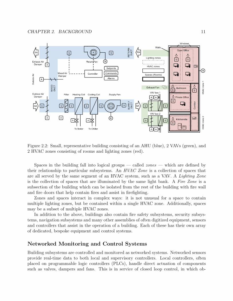
2.2 Small, representative building consisting of an AHU (blue), 2 VAVs (green), and2 HVAC zones consisting of rooms and lighting zones (red). . . . . . . . . . . . 11
2.3 Screenshot of a recently-deployed (2009) building management system . . . . . . 122.4 Different metadata representations used over the course of a building’s lifecycle . 152.5 Part of an IFC representation of a small, 2-story office building in Berkeley, CA 162.6 Part of an gbXML representation of a “big box” retail store. The AirLoop tag
contextualizes a set of equipment for a particular segment of the HVAC systemsupplying air to a zone . . . . . . . . . . . . . . . . . . . . . . . . . . . . . . . . 18
2.7 Graphical representation of part of a Modelica model representing a VAV with re-heat capability, sourced from the Buildings Library [150]. Modelica also supportsexporting to a JSON-based format [98]. . . . . . . . . . . . . . . . . . . . . . . . 19
2.8 Snippet of a document detailing point naming conventions for a particular BMSvendor . . . . . . . . . . . . . . . . . . . . . . . . . . . . . . . . . . . . . . . . . 20
2.9 A damper position command point described using Haystack tags, as seen in theCarytown reference model . . . . . . . . . . . . . . . . . . . . . . . . . . . . . . 20
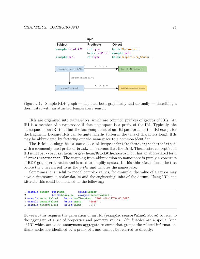
2.10 Simple, representative Brick model . . . . . . . . . . . . . . . . . . . . . . . . . 212.11 Generic RDF triple, consisting of a subject and object (nodes in a graph) and a
predicate (directed edge from subject to object) . . . . . . . . . . . . . . . . . . 232.12 Simple RDF graph — depicted both graphically and textually — describing a
thermostat with an attached temperature sensor. . . . . . . . . . . . . . . . . . 242.13 Example Turtle-formatted RDF graph for the Brick model depicted in Figure 2.10 262.14 Simple SPARQL query for the airflow setpoints and sensors associated with VAVs 27
3.1 Current practice: deploying software to different sites requires re-implementingand re-configuring the software for each site . . . . . . . . . . . . . . . . . . . . 30
3.2 Self-adapting software will query a metadata model of its environment in orderto automatically configure a single implementation to operate on new sites. . . . 31
3.3 A high level vision of self-adapting software interacting with the built environment 34
v
4.1 The set of valid (blue + solid outline) and invalid (red + dashed outline) tagsetsfor a set of four tags. The class hierarchy is established from top to bottom;subclassrelationships are indicated by arrows . . . . . . . . . . . . . . . . . . . . . . . . 45
4.2 An OWL-based ontology (right) encodes classes as named sets (left); a subclassrelationship between two classes means that all the members/instances of thesubclass are also members/instances of the superclass. . . . . . . . . . . . . . . 48
4.3 An example of a logical violation in an instance of a Brick+ model. . . . . . . . 514.4 SHACL node shapes validating use of the Brick+ hasPoint and isPointOf re-
lationships . . . . . . . . . . . . . . . . . . . . . . . . . . . . . . . . . . . . . . . 524.5 A SHACL shape enforcing the two possible uses of the isPartOf relationship. . 534.6 An erroneous SHACL shape for defining two required points for VAVs . . . . . 544.7 The correct SHACL shape for defining two required points for VAVs. . . . . . . 554.8 The three main class organizations for Brick+ entities . . . . . . . . . . . . . . . 564.9 The Brick+ definition of a temperature sensor. . . . . . . . . . . . . . . . . . . . 564.10 Part of the brick:Temperature Sensor class definition from Figure 4.9, showing
the unoptimized full implementation of the OWL intersection class . . . . . . . 584.11 SHACL-AF implementation of tag→class inference for the Brick+ Temperature Sensor
class. Figure 9.2 in the Appendix contains the full expanded shape. . . . . . . . 594.12 A subset of the Brick+ class lattice for sensors, showing the semantic properties
which characterize each class . . . . . . . . . . . . . . . . . . . . . . . . . . . . . 624.13 . . . . . . . . . . . . . . . . . . . . . . . . . . . . . . . . . . . . . . . . . . . . . 63
5.1 Logical workflow for application configuration and execution . . . . . . . . . . . 665.2 Three different Brick models describing the same physical system. It is possible
to author a single SPARQL query which will retrieve the names of the AHU anddownstream rooms, independent of the specific structure of the graph. . . . . . . 69
5.3 A SPARQL query which finds the AHU and two rooms in each of the graphs inFigure 5.2 . . . . . . . . . . . . . . . . . . . . . . . . . . . . . . . . . . . . . . . 70
5.4 Architecture of an application written in the staged programming model . . . . 715.5 Two SPARQL queries used in the qualify step of a rogue zone detection appli-
cation. . . . . . . . . . . . . . . . . . . . . . . . . . . . . . . . . . . . . . . . . . 725.6 Dataframe definition in Python (left) and the resulting dataframes (right) . . . 735.7 View definition in Python (left) and resulting table (right) . . . . . . . . . . . . 745.8 A simple clean stage implementation in Python which filters out periods of time
where either dataframe is missing a value . . . . . . . . . . . . . . . . . . . . . . 755.9 A analyze component implementation in Python for the rogue zone application
which finds periods where the measured airflow is lower than the setpoint. . . . 755.10 A simple program written using the interactive model that finds regions of time
when AHUs are both heating and cooling. . . . . . . . . . . . . . . . . . . . . . 775.11 The SPARQL query implied by the execution of the program in Figure 5.10 . . 775.12 Energy Baseline Calculation and Baseline Deviation Applications: Pre-
dicted baseline using [92] plotted against actual building energy consumption. . 79

vi
5.13 Heating coil and cooling coil valve commands over time for an AHU in a buildingdemonstrating simultaneous heating and cooling. . . . . . . . . . . . . . . . . . 82
5.14 A BAS [84] representation of a building’s electrical, lighting, spatial and HVACsubsystems . . . . . . . . . . . . . . . . . . . . . . . . . . . . . . . . . . . . . . 85
6.1 Original Haystack entity from the Carytown reference model . . . . . . . . . . . 926.2 Intermediate RDF representation of the Haystack entity; Haystack software-
specific tags (e.g. cur, tz) are dropped. . . . . . . . . . . . . . . . . . . . . . . 936.3 Brick inference engine splits the entity into two components: the explicit point
and the implicit outside damper equipment. . . . . . . . . . . . . . . . . . . . . 936.4 The distribution of the number of triples inferred per entity for each wrapper. . 956.5 The distribution of the total number of triples inferred by each wrapper. Note
the log-scale on the X axis . . . . . . . . . . . . . . . . . . . . . . . . . . . . . . 966.6 Different tools for different stages: Many different metadata standards and tech-
nologies are applied over the course of a building’s lifecycle, but are relativelysiloed and thus non-interoperable. . . . . . . . . . . . . . . . . . . . . . . . . . . 97
6.7 Overview of the proposed approach: wrappers interface directly with existingmetadata sources stored in local file systems, or accessed via file shares or net-worked services. Wrappers continuously publish inferred Brick metadata to acentral server, which produces a unified model. . . . . . . . . . . . . . . . . . . 98
6.8 Example record published by the BuildingSync wrapper, showing the originalmetadata (raw) and the inferred Brick metadata (triples). . . . . . . . . . . . 100
6.9 The phases of the reconciliation algorithm. The latest Brick metadata (far left)is stored by the integration server. . . . . . . . . . . . . . . . . . . . . . . . . . . 102
6.10 Example Brick metadata produced by BuildingSync and Project Haystack wrap-pers. The rdfs:label property denotes the original name or identifier of theentity in the metadata source. . . . . . . . . . . . . . . . . . . . . . . . . . . . . 104
6.11 The inferred unified metadata model for the triples in Figure 6.10. The mostspecific type is chosen for each entity, and that associated properties are carriedthrough. . . . . . . . . . . . . . . . . . . . . . . . . . . . . . . . . . . . . . . . . 104
6.12 Visualization of the campus meter database demonstrating how the semanticschange independent of the structure. Schema 1 was active until January 12th2012 at which point Schema 2 becomes the active schema. . . . . . . . . . . . . 108
6.13 Two different versions of the NSF degree taxonomy. Colored and outlined nodesare involved in either a split, merge or same relationship across versions. . . . . 112
7.1 Logical architecture of reasonable and its interaction with other software com-ponents of Mortar . . . . . . . . . . . . . . . . . . . . . . . . . . . . . . . . . . 118
7.2 Two OWL 2 RL rules expressed in Datalog. T is the relation (s,p,o) corre-sponding to the triples in an RDF graph. . . . . . . . . . . . . . . . . . . . . . . 119
7.3 Definition of the LIST[] syntax in [100] and an example of a variadic Datalogrule that uses a variable-sized list. . . . . . . . . . . . . . . . . . . . . . . . . . . 119
vii
7.4 The cax-sco rule implemented to take advantage of intermediate relations . . . 1217.5 Comparing performance of reasonable with OWLRL and Allegro over more than
100 Brick models. . . . . . . . . . . . . . . . . . . . . . . . . . . . . . . . . . . . 1237.6 Histogram of number of data streams for all sites (µ =241). . . . . . . . . . . . 1247.7 Mortar platform . . . . . . . . . . . . . . . . . . . . . . . . . . . . . . . . . . . 125
8.1 Technologies for design, operation, analytics, controls and modeling of buildingsare siloed and rarely interoperable . . . . . . . . . . . . . . . . . . . . . . . . . . 134
9.1 Brick expression of the building and subsystems illustrated in Figure 2.2 . . . . 1579.2 Expanded RDF graph for the shape described in Figure 4.11. . . . . . . . . . . 158

viii
List of Tables
4.1 An enumeration of the intended use and context of tags relating to heating andcooling, as given by the Haystack documentation. Note the differences in dictionacross compound tags, and how some compound tags could be assembled frommore atomic tags. Some tags are used both for equipment and for points whenequipment is modeled as a single point (such as VFDs, Fans, Coils) . . . . . . . 42
4.2 Brick+ relationships for associating entities with each other . . . . . . . . . . . 574.3 A set of semantic property name definitions . . . . . . . . . . . . . . . . . . . . 61
5.1 Applications: Brick LOC and App LOC indicate the lines of code needed to definethe Brick queries and application logic, respectively. “% coverage” is what pro-portion of the testbed’s buildings qualified for that application; the correspondingnumber of buildings is in the “# sites” column. . . . . . . . . . . . . . . . . . . 83
6.1 The results of merging multiple metadata models for two different sites, showingthe diversity of the metadata available between the available metadata sources.The % Contributed percentages do not add up to 100% because the rest of thegraph consists of inferred metadata not contained in any particular model. . . . 106
6.2 A subset of the split/merge/same relationships between the 2004 and 2010 ver-sions of the NSF degree taxonomy in Figure 6.13 . . . . . . . . . . . . . . . . . 111
7.1 Count of streams and equipment available in the testbed data set, aggregated bytype. AHU and VAV totals include related equipment such as fans and pumps. . 124
7.2 API operations supported on the Mortar platform. A ? suffix indicates the pa-rameter is optional. A [parameter] notation indicates the type is a list. . . . . 127

ix
Acknowledgments
The work described in this dissertation is the product of years of collaboration, mentorship,friendship and support from a number of people.
I would like to thank my advisor, David Culler, for being so generous with his time,experience and wisdom in guiding me through my PhD. Even when I was an undergraduateworking with one of his graduate students, David took the time to meet with me to discuss myresearch and, later, applications to graduate school. His ability to derive sharp insights frommy mess of thoughts was an invaluable resource that continues to inspire me to be a betterand more thoughtful researcher. I also owe a great deal to my other dissertation committeemembers, Joe Hellerstein, Stefano Schiavon and Marta Gonzalez, who have provided crucialperspective and feedback on my dissertation work.
My involvement in research is due to the mentorship and guidance of Andrew Krioukov,who asked me if I wanted to “hack buildings” during a research mixer in 2012. Our col-laborations and conversations underlie much of the work described in this thesis. Andrew,Stephen Dawson-Haggerty, Jay Taneja and Randy Katz and other members of the LoCalresearch group at Berkeley got me interested in the intersection of computer science and thebuilt environment and have provided valuable advice and support over the years.
As a graduate student, I had the privilege of working with a thoughtful, friendly andtalented group of people that all sat or worked together in 410 Soda as part of the Soft-ware Defined Buildings and Building, Energy and Transportation Systems research groups.Michael Andersen, Jack Kolb, Kaifei Chen, Sam Kumar, Moustafa AbdelBaky, Kalyanara-man Shankari and Hyung-Sin Kim were an endless source of ideas, discussions and advice— I have learned so much from each of you. Albert Goto has been a constant through it all:his friendship and support made many late nights and harrowing deadlines possible. Thegraduate student communities in the Berkeley CS department and the Computer ScienceGraduate Student Association have also been a wonderful support network over the years.
I have been extremely fortunate to work with very knowledgable, professional and caringadministrative staff over my time at Berkeley. Shirley Salanio and Jean Nguyen in thedepartment made sure I was on track to complete my degree, quickly answered any questionsI had, and helped me navigate various processes. Kattt Atchley and Boban Zarkovich in theRISE lab always had the time to help me through reimbursements and getting paid, and Ienjoyed our conversations about music and food.
Many thanks are due to my collaborators in the Brick community, who have helped megrow Brick into a recognized and increasingly adopted effort that is already influencing theindustry. Jason Koh, Dezhi Hong, Shreyas Nagare, Yuvraj Agarwal, Mario Berges, AmbujShatdal and Erik Paulson have each made unique and valuable contributions of their time,experience and ideas, and Brick is better for it. I am also indebted to my other colleagueswho have collaborated with me on many grants, projects and papers: Therese Peffer, PaulRaftery, Carlos Duarte, Anand Prakash, Marco Pritoni, Michael Wetter, Sascha von Meier,Keith Moffat, Ed Arens, Hui Zhang, Joyce Kim, Tyler Hoyt and Carl Blumstein. Over

x
my PhD, I have been generously supported by the California Energy Commission, the U.S.Department of Energy, the National Science Foundation, Johnson Controls, Intel and SRC.
I want to thank my family — Mom, Dad, Michael, Ollie, Ben, Angelo and Monica —for providing respite, demonstrating interest in my research and keeping me sane over theseyears. To my friends not mentioned above, Brandon, Karoun, Nathan, Ava and Max: Iwould not have made it through this program without your friendship, humor and excellenttaste in food and music. Lastly, to Sonia, my partner in everything: thank you for theunwavering support and compansionship. The best part of finishing my PhD is that I getto experience that with you.

1
Chapter 1
Introduction
The built environment — the buildings, utilities, infrastructure, cities and other constructedelements of the anthropocene — is becoming increasingly digitized. The complex array ofequipment, sensors and other devices in these environments constitute cyberphysical systemswhich produce an incredible volume of data. This data enables a broad family of data-driven use cases across many sectors of the built environment enacting energy efficient andresilient operation: monitoring, analysis and grid-aware control of buildings [127, 148, 137,111]; smart grids and distributed energy resources [132, 78]; and fault detection, predictivemaintenance and advanced controls for water treatment [5, 135, 34]. Despite the benefits ofthese kinds of data-informed applications, most are not widely adopted due to the prohibitivecost of accessing and understanding cyberphysical data [57].
Cyberphysical data is hard to access and understand because of the extreme heterogeneityand scale of the built environment: essentially every cyberphysical system is a custom-built “one-off” collection of equipment, devices and data sources that has been continuallyoperated, retrofitted, expanded and maintained over years or even decades. The processesimplemented by cyberphysical systems are diverse, complex and can be enacted in a numberof ways. Buildings alone contain different subsystems for heating, cooling, ventilation andtransporting different kinds of water, air, refrigerant and other substances, in addition tofire, security, lighting and other facility management systems. Each of these subsystems cancontain 10s or 100s of pieces of equipment, each monitored and controlled through a varietyof sensors and actuators from different manufacturers and speaking different protocols.
Heterogeneity presents a challenge for the development and deployment of software incyberphysical settings. Each cyberphysical system is so different that software must bewritten with specific knowledge of the structure, composition and function of the particularcyberphysical system at hand. However, there is no standard representation of these systemsthat can facilitate such an understanding. The cyberphysical data required by applicationsis poorly labeled, often following ad-hoc naming conventions that usually do not containmachine-readable information about the source, context or significance of the data. Datascientists already spend upwards of 40% of their time gathering, cleaning and understandingdata [68]. This task is further impeded by a lack of standard representations that encode

CHAPTER 1. INTRODUCTION 2
this metadata in a structured manner [112, 64, 19, 4]. Without such representations, therollout of energy efficiency and other data-driven measures involves customizing softwareimplementations to each potential deployment site.
This thesis proposes a method for the mass-customization of data-driven cyberphysicalsoftware. Applications will be able to query their environment for the contextual clues andmetadata that they need to customize their own behavior, i.e. to choose an appropriatealgorithm to run or model to train based on the kind of cyberphysical system deployed andthe data that is available. Such self-adapting software requires rich, semantic and machine-readable descriptions of the built environment that can represent the necessary information,regardless of the complexity and uniqueness of the cyberphysical system. This chapter sum-marizes how data is usually managed for cyberphysical systems, including current practicesfor metadata in the built environment. Then, the chapter identifies four key challenges torealizing self-adapting software and presents the central thesis statement and roadmap.
1.1 Software for Cyberphysical Systems
The intent of cyberphysical software is to extract data about the physical world in order toinform some decision-making process. Data may inform diagnostic or descriptive processes,such as dashboards displaying the current status of a system or alarms which detect faultsor errors within the system. Data may also drive prescriptive processes that use modelsto predict when equipment will break or inform a control decision about how to achieve acertain goal. The digitization of cyberphysical systems, a phenomenon sometimes referredto as the “industrial internet of things”, will increase both the variety and availability ofdata. This presents new opportunities for innovative uses of data across many sectors of thebuilt environment: from building management to smart grids to renewable energy resourcesto water management and transportation.
At the same time, the characteristics of cyberphysical systems are such that making ef-fective use of data requires a substantial investment of time, money and technology. Thenetworked infrastructure that allows data to be collected and commands to be sent to actu-ators is designed around the constraints of the small, primitive controllers and sensors thatare embedded in the physical world. Historically, in these settings, memory and storagespace is at a premium. Any available space is mostly devoted to storing programmable logic,data registers and mechanisms necessary to implement an industrial communication protocolsuch as BACnet, Modbus, LonTalk or OPC. The protocol handles the receipt and deliveryof data to and from the sensors and controllers in the environment. Metadata, the data thatdescribes the data sources, is usually an afterthought.
Consequently, cyberphysical systems rarely support more than a simple text field forcapturing the name or description of each data source. These names are often the onlyavailable descriptions of the data sources, and are sometimes the only available metadataabout the entire cyberphysical system. The structure of these names is idiosyncratic andfollow ad-hoc conventions and idioms which are site-specific and often inconsistently applied.

CHAPTER 1. INTRODUCTION 3
Data
CPS Application
ReconfigurationReimplementation
Data
CPS Application
ReconfigurationReimplementation
Data
CPS Application
ReconfigurationReimplementation
Data
CPS Application
ReconfigurationReimplementation
Figure 1.1: Current practice: deploying software to different sites requires re-implementingand re-configuring the software for each site
These names must serve as the digital “breadcrumbs” that allow an application developerto find the data sources they need. However, due to the lack of structured information,correctly and completely interpreting the names is a manual, time-consuming and error-prone task. This task is difficult to perform without an expert-level knowledge of how kindsof cyberphysical systems work and how the installer of the system decided to name thedata [27, 25, 82, 131].
The lack of structured metadata has a significant impact on how software is written forcyberphysical systems. The complexity and uniqueness of cyberphysical systems means mostsoftware is authored for a particular cyberphysical system. Software uses hard-coded datasource names to fetch required telemetry during operation. The algorithm, model and otheraspects of the application are chosen with knowledge of how the deployment will look, whatdata sources and actuators and controllers are available, and what kinds of computationalmethods are the most appropriate. Most cyberphysical applications are written in this non-portable manner. Deploying a particular application in a variety of environments requiresderiving an understanding of each environment, discovering the available data sources, andrewriting the application logic accordingly (Figure 3.1) [84]. The result is that most data-driven cyberphysical applications are not deployed at a large scale.
1.2 Thesis Question
Prior work calls for better, standard metadata which facilitates wider adoption of data-drivencyberphysical applications [19, 4]. However, this vision has yet to be realized. This thesisaddresses fundamental barriers to enabling data-driven software for a variety of cyberphys-

CHAPTER 1. INTRODUCTION 4
ical systems by examining the relationship between how those systems are described andhow software is written for them. Specifically, how can we construct and manage seman-tically rich, structured representations of complex cyberphysical systems which inform theautomated customization and configuration of software? To answer this question, this thesisenvisions a new paradigm, self-adapting software, in which software uses information aboutits cyberphysical environment to discover relevant data and execute appropriate applicationlogic with minimal human intervention1.
1.3 Challenges for Self-Adapting Software
There are four challenges to realizing self-adapting software for cyberphysical system.
Challenge #1: Descriptions of Heterogeneous Environments
The foundation of self-adapting software is a digital representation of the built environmentthat captures the information necessary for self-adaptation. These environments may containdifferent kinds of equipment, connected in different ways to enact different physical processesand are monitored and controlled in different ways. Despite this heterogeneity, software muststill be able to discover salient details without any external or human-driven intervention.A key challenge is the definition of a metadata model that can effectively describe a varietyof cyberphysical environments. Which principles should inform the design of the metadatamodel, and how should the model be expressed and queried?
Challenge #2: Effective Programming Model
Given the potential complexity of the cyberphysical systems at hand, it is not obvious howself-adapting software should be written. Traditional programming techniques for cyber-physical systems are still dominated by so-called “expert systems” which use if-then rules toexpress application logic, despite these practices falling out of mainstream use in other sec-tors [65]. This produces rigid programs that are constructed around the needs of a particularenvironment. The rich and detailed digital representations of cyberphysical environmentswill require a more expressive programming model. What does this programming modellook like, and how can it make effective use of the available metadata?
Challenge #3: Metadata Management Over Time
Change is inevitable. Digital representations must be kept up-to-date with the cyberphysicalenvironments they describe, and software must be able to make use of emerging information.Furthermore, the digital representations enabling self-adapting software must be created inthe first place. A challenge for self-adapting software systems is how to bootstrap and
1More complete definitions of self-adapting software are examined in Chapter 3 and later in Chapter 5.

CHAPTER 1. INTRODUCTION 5
maintain the metadata representations, and how to detect and incorporate any changes inthe environment into the model. What systems, protocols and techniques best support themanagement of cyberphysical metadata over time?
Challenge #4: Metadata Management At Scale
The value of self-adapting software is its potential to enable the adoption data-driven prac-tices at the scale of thousands or even millions of environments, each with their own uniquestructures and representations. The databases, query processors and application runtimesthat support self-adapting software must be built to accommodate heterogeneity at scale.
This dissertation argues that existing barriers to widespread adoption of software-drivensustainable practices can in part be overcome through the adoption of rich, semantic meta-data. This presents challenges for the form, curation and maintenance of this metadata, andraises questions for how to effectively program against this metadata. This work proposesnew semantic metadata management practices and techniques, a new programming model— self-adapting software — and novel data platforms which address these challenges.
1.4 Approach and Thesis Roadmap
To address these challenges and answer the thesis question, this thesis proposes the following:
• a linked-data ontology formally defining a graph-based data model for describing het-erogeneous cyberphysical environments in buildings, and a set of ontology design prin-ciples for future ontologies targeting other sectors of the built environment;
• new programming models for using graph-based metadata to author self-adapting ap-plications;
• techniques and a system for continuously maintaining metadata models of cyberphys-ical environments, even as those environments change;
• a data management system for storing, serving and managing metadata at scale.
These propositions are explored and evaluated over the following chapters.Chapter 2 reviews the structure, composition and function of common cyberphysical
systems that are potential targets of self-adapting software. The chapter provides an overviewof current metadata practices for such cyberphysical systems, including recent academic andcommercial work, and identifies existing holes where those practices fall short of enabling self-adapting software. The chapter summarizes ontologies and other linked data technologiesthat underlie the metadata model developed later.
Chapter 3 uses the background knowledge covered in Chapter 2 to more precisely illus-trate the intended approach to self-adapting software described in this thesis. An architec-ture of a self-adapting software system is described, and the chapter outlines how each ofthe challenges above are addressed by components of the architecture.

CHAPTER 1. INTRODUCTION 6
Chapter 4 covers the design and implementation of a linked data ontology, Brick, whichprovides a semantically-rich and descriptive representation of cyberphysical systems in build-ings. The chapter establishes crucial design principles that make Brick successful — inter-pretability, consistency and extensibility — and demonstrates how current popular metadatamodels fail to provide these properties. The chapter details how Brick implements theseproperties using formal logic.
Chapter 5 presents the design of two different programming models for self-adaptingsoftware: a staged execution model and an interactive execution model. The chapter explainshow the models operate and how they may be implemented. The efficacy of the stagedmodel is proved through the self-adapted execution of a family of representative data-drivenapplications over many real-world buildings.
Chapter 6 discusses how semantic metadata can be managed and maintained over time.The system presented in the chapter focuses on how this metadata can be inferred, minedor otherwise extracted from existing digital representations. These representations may bestructured, semi-structured or unstructured. The chapter describes an algorithm which rec-onciles differences between the metadata extracted from several representations and mergesthese into a single, cohesive, model supporting self-adapting applications. The chapterpresents the implementation of this approach in a real system and the evaluates its behavioron a set of real-world environments.
Chapter 7 presents two systems which support the storage, management and serving ofmetadata models and timeseries data to support self-adapting applications. reasonable is asoftware package which abstracts away the computationally expensive and time consumingcomponents of ontology management behind a simple and performant interface. This facili-tates the incorporation of linked data into existing databases. The second system, Mortar,is a data platform which hosts semantic metadata and timeseries data together to supportdata-driven and self-adapting analytics.
Chapter 8 reflects on how Brick, Mortar and other technologies and ideas described inthis thesis are influencing data-driven practices in academia, industry and standards bodies.
Chapter 9 presents future work and conclusions, including a discussion on what othersectors of the built environment could be served by technologies like Brick and Mortar.

7
Chapter 2
Background
This chapter provides necessary background on cyberphysical systems in the built environ-ment and the linked data technologies that will be leveraged to effectively describe them.
2.1 Cyberphysical Systems in the Built Environment
Cyberphysical systems, typified by the “Internet of Things” are engineered systems that areembedded in the physical world and provide networked sensing and actuation capabilities.These kinds of systems are ubiquitous in many facets of the built environment, includingbuilding operations and management, water transportation and treatment, power grid oper-ations and transportation system management.
Above all, cyberphysical systems are characterized by extreme heterogene-ity: any given cyberphysical system is an idiosyncratic assembly of equipment and otherdevices that has been custom-designed for a particular physical deployment. Cyberphysicalsystems are also constantly evolving. This is true both in the sense that recently designedcyberphysical systems often use newer and more efficient equipment and processes, but alsoin the sense that deployed cyberphysical systems experience repairs and retrofits that affecttheir composition and behavior.
This section provides a high-level overview of the kinds of cyberphysical systems that willbe studied in this dissertation — primarily those in buildings — and reflect on how thesesystems characterize the challenges addressed by this work.
Cyberphysical Systems in Buildings
Buildings provide an excellent case study of the heterogeneity and complexity of cyberphys-ical systems. Modern buildings are often composed of several different subsystems, whicheach fulfill a distinct purpose.

CHAPTER 2. BACKGROUND 8
Figure 2.1: Figure A-2 from ASHRAE’s Guideline 36 [73], depicting a prototypical VariableAir Volume box with reheat capability.
HVAC Subsystems
Heating, Ventilation and Air Conditioning (HVAC) subsystems manage the heating, venti-lating, or air conditioning processes within a building. These systems vary widely in theirconstruction and in the physical processes they use to achieve their goal, but there are severalbroad features that are common to most. The primary goal of HVAC systems is to heat, cooland ventilate spaces in the building. This can be accomplished using a number of physicalmechanisms, the most common of which heats and cools the air supplied to different parts ofthe building (so-called “air-based HVAC”). This requires equipment to distribute and con-trol the flow of the air, such as fans and dampers, which are often independently monitoredand controlled using sensors embedded in the building and air distribution system. Thereare many different processes for heating and cooling air, most of which involve introducinga heat exchanger into the stream of air. Heat exchangers may be electric or gas-powered,or they may use hot or cold water which is supplied by distinct subsystems referred to as“hot water” and “cold water” loops. “Radiant systems” are an alternative design in whichhot or cold water is pumped through pipes embedded in concrete slabs which then radiateor absorb heat to modulate the temperature in a space.
Each of these HVAC functions can be provided by a variety of equipment. Some majortypes of equipment include:
• Air Handling Units (AHUs): a large unit often containing dampers, fans or blowers,filters, heating and cooling elements that regulates and conditions air that is suppliedto a building via connected ducts. AHUs are typically part of large HVAC installations.
• Terminal Unit: a smaller unit, typically downstream of an AHU, that regulates airvolume, temperature or both and is connected directly to spaces in the building. A

CHAPTER 2. BACKGROUND 9
Variable Air Volume box (VAV) is one common flavor of terminal unit (Figure 2.1)which incorporates a damper to regulate air volume.
• Rooftop Units (RTUs): a unit that contains all or most of the functionality of an AHUand VAV system, but in a single “packaged unit”. Typically installed in small andmedium-sized office buildings and is connected to a thermostat
The choice of equipment for a particular HVAC system depends on the needs of the build-ing, including floor area, climate and projected occupancy. There are also many potentialdifferences between equipment of similar classification (e.g. VAV). Manufacturers may in-corporate different sensors, mechanisms, actuators and technologies into their equipment inorder to provide more efficient operation or advanced control and fault detection strategies.
The behavior of HVAC systems is governed by a variety of control mechanisms, rangingfrom simple schedules to “sequences of operations” to advanced data- and model-drivenoptimal controllers. In all cases, HVAC systems make use of a variety of sensors whichreport the physical state of the system (such as the temperature and volume of air flowingto a room) and setpoints which constitute the targets or bounds of a controllers activity.Sequences of operations, such as those described in ASHRAE Guideline 36 [73], lay outprecise rules for how to actuate components of an HVAC system in response to differentrelationships between sensed and measured values, and control setpoints.
Lighting Subsystems
Lighting subsystems serve many different roles, including exit lighting and fulfilling mini-mum levels of illumination for different occupant activities. These systems consist mostly ofluminaires, which are devices consisting of a lighting element and enclosure. Luminaires arepowered by drivers, which may regulate voltage and connect to a networked control system.Similar to HVAC, lighting control systems may operate on a simple schedule with manualcontrol overrides (i.e. a wall switch for lighting, thermostat for HVAC). Advanced lightingsystems operate by measuring illumination and sensing occupancy in the spaces served byone or more luminaires, and controlling lights and lighting fixtures to meet control targetsor save energy.
Water Subsystems
Buildings contain several kinds of water systems, which typically consist of non-overlappinggroups of equipment and are often siloed from one another.
• Chilled Water Loop: water is chilled through some mechanism (such as evaporation, orexternal coolant), and distributed throughout the building. In many HVAC systems,valves control water flow into coils placed in the air stream; modulating the valve inresponse to sensed water and air temperature allows fine-tuned control of downstreamair temperature

CHAPTER 2. BACKGROUND 10
• Hot Water Loop: water is heated through some mechanism and distributed throughoutthe building. Similar to chilled water loops, valves control the flow of hot water intocoils placed in the air stream.
• Irrigation: water, from many potential sources, is distributed around a site or buildingin order to water plants. Water usage is metered and irrigation typically occurs onsome schedule. Occasionally, sensors are deployed which provide feedback on the pHand hydration of soil
• Plumbing: water supplying bathrooms, kitchens and other human-facing building as-sets is also distributed and metered
Each of these systems incorporates a variety of sensors, setpoints, alarms and actuatorswhich are used to drive controllers and user interfaces.
Electrical Subsystems
Electrical subsystems transform and transport electricity which is used to power the equip-ment involved in the above subsystems, as well as the multitude of electrical assets containedwithin the building. The lowest common denominator for electrical subsystems is the wiringsupplying AC power to building assets, and the meter attached at the point between a build-ing and the electric grid, which meters the amount of electricity flowing in either directionfor the primary purpose of charging for usage.
Inside buildings, the electrical subsystem can be thought of as a tree with the mainbuilding meter as the root, and submeters and electrically-powered assets as the children.Submeters may be installed to independently monitor subsystems in the building; for examplea submeter may measure all electricity used to power the HVAC system, or even just thechilled water loop.
The increasing penetration of renewable energy resources deployed at building sites —such as photovoltaic arrays and geothermal systems — in addition to the growing adoptionof electric vehicles has introduced new families of supporting equipment which may be foundat a site. These include inverters, voltage regulators and different kinds of batteries.
Spatial “Subsystems”
The set of logical, physical and administrative spaces that make up a building are not a“subsystem” in a traditional sense, but it is useful to treat these concepts as if they werea complex arrangement of equipment. Familiarly, buildings can be broken down into floorsand rooms, but there are common concepts that do not fit cleanly into this formalization:what floor do stairs, elevators and atriums reside on? Is each cubicle in an office space itsown room? Rooms can have many different uses, depending on the time of day, day of theweek, time of the year or even the occupant or owner of a room.
CHAPTER 2. BACKGROUND 11
Figure 2.2: Small, representative building consisting of an AHU (blue), 2 VAVs (green), and2 HVAC zones consisting of rooms and lighting zones (red).
Spaces in the building fall into logical groups — called zones — which are defined bytheir relationship to particular subsystems. An HVAC Zone is a collection of spaces thatare all served by the same segment of an HVAC system, such as a VAV. A Lighting Zoneis the collection of spaces that are illuminated by the same light bank. A Fire Zone is asubsection of the building which can be isolated from the rest of the building with fire walland fire doors that help contain fires and assist in firefighting.
Zones and spaces interact in complex ways: it is not unusual for a space to containmultiple lighting zones, but be contained within a single HVAC zone. Additionally, spacesmay be a subset of multiple HVAC zones.
In addition to the above, buildings also contain fire safety subsystems, security subsys-tems, navigation subsystems and many other assemblies of often digitized equipment, sensorsand controllers that assist in the operation of a building. Each of these has their own arrayof dedicated, bespoke equipment and control systems.
Networked Monitoring and Control Systems
Building subsystems are controlled and monitored as networked systems. Networked sensorsprovide real-time data to both local and supervisory controllers. Local controllers, oftenplaced on programmable logic controllers (PLCs), handle direct actuation of componentssuch as valves, dampers and fans. This is in service of closed loop control, in which ob-

CHAPTER 2. BACKGROUND 12
Figure 2.3: Screenshot of a recently-deployed (2009) building management system
servations from the environment influence future control actions in order to meet a controltarget, commonly called a setpoint. Common examples of closed loop control include tem-perature control: a controller calls for heating or cooling of supplied air in order to adjustthe temperature.
Local controllers receive control targets from networked, supervisory controllers whichsend commands to devices over the network and monitor the status of devices and the valuesof sensors. Supervisory controllers commonly implement schedules, but can also coordinatethe behavior of groups of devices to implement advanced control strategies.
Building Management Systems (BMS) are networked, digital control systems that imple-ment supervisory control and provide programming environments and graphical user inter-faces that facilitate the management of the building. These interfaces (Figure 2.3) illustratethe current state of equipment and offer configuration of schedules, direct override controlof devices, and often simple trending and fault detection capabilities. A 2018 survey of U.S.commercial buildings found that 70% had digital HVAC controls and 50% had digital lightingcontrols [86]. This is up from the 10% of commercial buildings in the U.S. in 2005 [29]. How-ever, the adoption of automated fault detection and building energy management systemswas only 4%. BMS speak using protocols such as BACnet [14] and LonTalk.
Relevant to the work in this paper, each subsystem in a building may have its ownBMS. These BMS are usually installed at different times, by different companies, and may

CHAPTER 2. BACKGROUND 13
speak different protocols. Systems deployed in this way are said to be siloed. This presentsintegration challenges for any users of the system — human or software.
Supervisory Control and Data Acquisition (SCADA) systems are a common example ofdigital control systems that are not BMS. SCADA systems speak protocols such as Mod-bus [96], and are commonly found implementing industrial processes such as water manage-ment and manufacturing.
In contrast with the planned and designed nature of BMS and SCADA are the networkeddevices typical of the Internet of Things. These devices are deployed in a piecemeal and ad-hoc fashion, but implement a wide array of functionality and are being deployed at anincreasing rate. Examples of IoT devices include temperature, CO2 and other sensors,thermostats, lights, plug load controllers, blenders, televisions, refrigerators and even bedsand toasters. The promise of IoT is in ensembles of smart devices that can collaborateto save energy, increase comfort, or provide other automated conveniences. However, inpractice, the IoT is plagued by fragmentation at the physical network level (devices mayspeak Bluetooth, WiFi, Zigbee, Enocean, Thread or any one of a number of other physicallayers), network level and application level; this results in even more dramatic siloing thanis found within the BMS domain. Industrial collaborations such as Connected Home OverIP [161] aim to standardize the application layer so that devices from different manufacturersmay communicate.
2.2 Definitions
The following terms are used throughout the thesis and are defined here for clarity.
Definition 2.2.1 (Metadata). Metadata for cyberphysical systems comprises the digital rep-resentations and descriptions of the structure, composition, identity and functionality ofcyberphysical systems, as well as their composing elements.
Definition 2.2.2 (Metadata Representation). A metadata representation is a data model,schema, standard or convention which defines the structure, syntax and/or semantics ofthe metadata that can be expressed. Structure is the organization of metadata into datastructures, objects and relationships. Syntax is the encoding and rules for how that metadatacan be expressed and communicated. Semantics is the use of logical rules and statements toencode the “meaning” of metadata.
Definition 2.2.3 (Metadata Model). A metadata model is an instance of a metadata rep-resentation. It contains the metadata for a particular site, deployment or other scoped col-lection of “stuff”.
Definition 2.2.4 (Tag). A tag is an atomic fact, annotation or attribute consisting of andidentified by a simple textual label.

CHAPTER 2. BACKGROUND 14
Definition 2.2.5 (Entity). An entity is an abstraction of any physical, logical or virtualitem; the actual “things” in a building.
Definition 2.2.6 (Tag Set). A tag set is an (unordered) set of tags associated with an entity.
Physical entities are anything that has a physical presence in the world. Examples aremechanical equipment such as air handling units, variable air volume boxes, luminaires andlighting systems, networked devices like electric meters, thermostats and electrical vehiclechargers, and spatial elements like rooms and floors.
Virtual entities are anything whose representation is based solely in operational software,such as a BMS or SCADA system. Examples are sensing and status points that allow softwareto read the current state of the world (such as the current temperature of air, the speed of afan, or the energy consumption of a space heater), and actuation points which allow softwareto write values (such as temperature setpoints or the brightness of a lighting fixture).
Logical entities are those entities or collections of entities that are defined by a set ofrules. Examples are HVAC zones and Lighting zones. Concepts such as class names andtags also fall into this category.
2.3 Metadata for Cyberphysical Systems
It has been said that “All models are wrong, but some are useful” [28]; this is as truefor digital representations of cyberphysical systems as it is for the statistical models thatare the subject of the original statement. The only “complete” or “correct” representationof a cyberphysical system is one that is 1-1 with both the digital (“cyber”) and physicalworlds. The intractability of such a model means that the metadata representations thatare the study of this thesis are necessary simplifications. The effective design of a metadatarepresentation of a building is rooted in choosing appropriate simplifications and abstractionsthat best support the intended use cases [54]. This section reviews prevailing approachesfor metadata for cyberphysical systems and discusses their advantages, shortcomings andtrade-offs.
Prevailing Metadata Representations for Buildings
Metadata representations for buildings capture different perspectives and levels of detail onbuildings, their control systems, their subsystems, and the components therein. The intendeduse cases of a metadata representation inform the particular structure, syntax and semanticsof the representation. One convenient way to categorize these perspectives is through thelens of the building lifecycle.
A Building Lifecycle Framing
The lifecycle of a building can be separated into several stages, each with their own partici-pants, stakeholders and — importantly — metadata representations. Most existing research

CHAPTER 2. BACKGROUND 15
CommissioningConstructionDesign Operation
Maintenance
Audit
IFC, gbXML, CDL, Modelica
IFC, gbXML, CDL
BMS,Haystack, CDL, Brick
Brick, Haystack
BuildingSync
Small Retrofit
Large Retrofit, Renovation
IFC, gbXML
Figure 2.4: Different metadata representations used over the course of a building’s lifecycle
into the building lifecycle uses a two or three stage categorization [143, 125] consisting of adesign and construction phase, an operational phase, and a demolition or end-of-life phase.This discussion further subdivides the building lifecycle in order to call attention to thedifferent metadata representations used.
Figure 2.4 presents a building lifecycle, with each stage represented as a box withcommonly-used metadata representations. Briefly, these stages are:
• Design: During the design phase of a building, decisions are made about the layout,architecture and composition of the building and its subsystems, given specificationsabout the intended use and occupancy of the building.
• Construction: During the construction phase of a building, the design specificationsfrom the prior phase are executed and realized in the physical world.
• Commissioning: During the commissioning phase of a building, sequences of op-erations for building subsystems are designed and implemented, and the building ismeasured to evaluate whether it meets the design specification as laid out in the de-sign phase.
• Operation: The operational phase of the building consists of the use of the buildingand the operation and management of its subsystems. Typically the operational phaseof the building is the longest.
• Maintenance: Buildings may undergo maintenance when the building is not operatingas expected, for example due to broken equipment.
• Auditing: (Energy) audits are formal processes that evaluate the performance of abuilding relative to external standards or guidelines. Audits are typically conductedat regular intervals of a building’s lifespan. For example, buildings in New York Cityover 50,000 square feet must be audited every 10 years [159].

CHAPTER 2. BACKGROUND 16
1 #114= IFCPOSTALADDRESS($,$,$,$,('Enter address here'),$,'2087 Addison St','Berkeley','',
2 'CA 94704');
3 #118= IFCBUILDING('1W9$dXIRj77hKpdvvBeVIz',#41,'',$,$,#32,$,'',.ELEMENT.,$,$,#114);
4 #124= IFCCARTESIANPOINT((0.,0.,-20.));
5 #126= IFCAXIS2PLACEMENT3D(#124,$,$);
6 #275062= IFCRELCONTAINEDINSPATIALSTRUCTURE('2p7RyAcN5DYP3YLiEj0ALn',#41,$,$,(#249085),#3066);
7 #269932= IFCSITE('1W9$dXIRj77hKpdvvBeVI_',#41,'Default',$,'',#269931,$,$,.ELEMENT.,
8 (37,52,16,47363),(-122,-16,-6,-549682),0.,$,$);
9 #131= IFCAXIS2PLACEMENT3D(#6,$,$);
10 #132= IFCLOCALPLACEMENT(#32,#131);
11 #133= IFCBUILDINGSTOREY('1W9$dXIRj77hKpdvwqNWjI',#41,'Level 1',$,$,#132,$,'Level 1',.ELEMENT.,0.);
12 #135= IFCCARTESIANPOINT((0.,0.,17.1666666666667));
13 #137= IFCAXIS2PLACEMENT3D(#135,$,$);
14 #138= IFCLOCALPLACEMENT(#32,#137);
15 #139= IFCBUILDINGSTOREY('1W9$dXIRj77hKpdvwqNYsM',#41,'Level 2',$,$,#138,$,'Level 2',.ELEMENT.,
16 17.1666666666667);
17 #141= IFCAXIS2PLACEMENT3D(#6,$,$);
18 #142= IFCLOCALPLACEMENT(#132,#141);
19 #144= IFCCARTESIANPOINT((3.55271367880050E-15,-8.88178419700125E-15));
20 #146= IFCAXIS2PLACEMENT2D(#144,#23);
21 #147= IFCRECTANGLEPROFILEDEF(.AREA.,$,#146,9.33333333333333,14.5116423880952);
Figure 2.5: Part of an IFC representation of a small, 2-story office building in Berkeley, CA
Issues uncovered during maintenance or auditing may result in retrofits, which may be asminor as updating control sequences and installing new equipment, or as major as adding/re-moving rooms or replacing the entire HVAC system. Retrofits experience the same broadphases of the building lifecycle, and often make use of the same metadata representations.
Building Information Modeling
Building information modeling (BIM) is a broad category of metadata representations thatare designed to capture and communicate the properties of buildings, subsystems and con-stitutent equipment that are relevant for the design and construction phases of the buildinglifecycle. BIM representations commonly store the geometry of the building and its compo-nents, but can also capture the layout and connection of pipes, wires and other connectionsbetween equipment. The two major metadata standards for BIM are IFC and gbXML.
Industry Foundation Classes
Industry Foundation Classes (IFC) [1] is a standard format and data model for the exchangeof data related to the design and construction of a building. This includes equipment andother assets, basic telemetry, wiring and connections between equipment, and the geometryand architecture of the building and its components. The IFC standard describes manycommon types of HVAC and lighting equipment as well as the sensors dispersed throughoutthe building.

CHAPTER 2. BACKGROUND 17
IFC models do not capture the context of the equipment contained within. For example,an IFC model will contain a representation of the many fans in a particular building, butwill not directly represent the configuration of those fans. The representation of a faninstalled in a supply configuration (blowing air into a zone) will be indistinguishable fromthe representation of a fan installed in an exhaust configuration (blowing air out of a zone).A human expert looking at the IFC model will be able to differentiate the two configurationsbased on their familiarity with supply and exhaust systems, but the IFC model itself doesnot label the fans as such.
IFC models are expressed in the EXPRESS format (Figure 2.5), which presents chal-lenges for integration with external tools. There are current efforts to develop more usablerepresentations of IFC models, such as using RDF and OWL [115].
Green Button XML
Green Button XML (gbXML) [60] is an XML-based data model for the exchange of BIM data.gbXML focuses on capturing the 3D geometry of the equipment and spaces in a building.In constrast to other BIM representations like IFC, gbXML provides contextual informationabout a building’s components by grouping related equipment and spaces together (Fig-ure 2.6). The XML tags, attributes and enumerated values defined by the gbXML standardalso include more contextual information about how building components are connected andconfigured.
Modelica
Modelica is a declarative, equation-based modeling language used to describe engineeredsystems [97]. Modelica decomposes systems into modular objects — defined by the user orin external libraries — which are coupled to each other to form systems (see Figure 2.7). Theconnections between Modelica components are objects themselves, and can have propertiesattached to them. Connections represent input and output ports for control signals as wellas physical ports, such as the valve flange through which fluid flows. A model created withModelica can be used for simulations of different system configurations, control strategiesand equipment. Modelica’s use is not limited to buildings, and many different libraries areavailable which define modular components for different domains. The Modelica BuildingsLibrary [150] defines common component and system models for building and district energyand control systems. However, it is possible to define new or extend existing Modelicacomponents for buildings that are not contained in the library.
Control Description Language
The Control Description Language (CDL) is a subset of Modelica used to express control se-quences for building automation systems in a digital and vendor-independent manner [149].By standardizing the representation of control sequences, CDL aims to facilitate the design,specification, deployment and verification of common and emerging control strategies [151].

CHAPTER 2. BACKGROUND 18
1 <AirLoop id="West2" systemType="VariableAirVolume" controlZoneIdRef="aim19233">
2 <Name>Air loop</Name>
3 <Description>West exterior system using schedule 'FanSch-17' on the bottom floor
4 interior system using schedule 'FanSch-17' on the bottom floor </Description>
5 <TemperatureControl>
6 <MinTemp unit="C">11.1</MinTemp>
7 <MaxTemp unit="C">48.9</MaxTemp>
8 </TemperatureControl>
9 <AirLoopEquipment id="West2-Equip-8" equipmentType="Duct">
10 <Name>3.5" wg static VAV duct system</Name>
11 <Description>3.5" wg static pressure duct system</Description>
12 <DeltaP unit="Pascals">-870.799987792969</DeltaP>
13 <Cost>4.1</Cost>
14 </AirLoopEquipment>
15 <AirLoopEquipment id="West2-Equip-2" equipmentType="Fan">
16 <Name>Std VAV Fan with variable speed drive (VSD)</Name>
17 <Description>Forward curved fan and premium efficiency motor typically used
18 for larger packaged and AHU equipment.</Description>
19 <OperationSchedule scheduleIdRef="FanSch-17" />
20 <MinFlow unit="Fraction">0.3</MinFlow>
21 <DeltaP unit="Pascals">870.799987792969</DeltaP>
22 <Power powerType="Electricity" useType="Both" />
23 <Efficiency standardsType="NEMA" operationType="HeatingAndCooling"
24 efficiencyType="MotorEff">0.93</Efficiency>
25 <Efficiency standardsType="No Defined" operationType="HeatingAndCooling"
26 efficiencyType="MotorEff">0.75</Efficiency>
27 <Control controlType="Fan" stages="Variable " />
28 <Cost>0.733</Cost>
29 </AirLoopEquipment>
30 </AirLoop>
Figure 2.6: Part of an gbXML representation of a “big box” retail store. The AirLoop tagcontextualizes a set of equipment for a particular segment of the HVAC system supplyingair to a zone
CDL sequences can be integrated with building models expressed in Modelica, permittingthe simulation and evaluation of control sequences before they are deployed on actual hard-ware In fact, the Modelica Buildings library already contains CDL representations of highperformance HVAC control sequences. CDL-driven simulations enable comparing the per-formance different control sequences, testing their correct specification, and commissioningtheir correct implementation in buildings.
Building Management System Metadata
In contrast with the structured and standardized representations detailed above, the meta-data found in building management systems largely consists of ad-hoc text labels for thetelemetry “points” that are exposed from the underlying digital control system. These la-bels are often rendered on a web interface (see Figure 2.3) that is exposed to a buildingor facility manager. Because these labels are simple strings, their structure is sometimes(but not always) informed by a site- or vendor-specific naming convention often consisting

CHAPTER 2. BACKGROUND 19
Figure 2.7: Graphical representation of part of a Modelica model representing a VAV withreheat capability, sourced from the Buildings Library [150]. Modelica also supports exportingto a JSON-based format [98].
of abbreviations describing related components or relevant features (Figure 2.8). These la-bels have several limitations. First, the lack of a standard structure (between BMS, andsometimes even within a BMS) means that it is difficult to extract any metadata aboutthe building in a structured manner. Conventions and idioms are rarely written down, areinconsistent between systems (even those from the same vendor), or may not exist at all fora particular site. Second, the point labels only exist for sources of telemetry and controlsignal sinks, and do not describe the actual structure of the building subsystem they aremonitoring or controlling.
As an example, consider a real BMS point label from the Computer Science departmentbuilding on the UC Berkeley campus: SODA1R410 ART [25]. This label contains severalpieces of metadata. First, the type of the point is communicated by the ART substring: aroom air temperature sensor. The name of the room is given by R410; R identifies thatthe identifier 410 is for a room. Next, the name of the AHU supplying air to the room isdenoted by A, and the identifier points out that AHU 1 is upstream of this room. Lastly,SOD indicates which building the sensor, room and AHU are located in.
Project Haystack
Project Haystack1 is a commonly-used tag-based metadata scheme for buildings that usesatomic tags and key-value pairs in place of unstructured labels to describe buildings, equip-ment and points [118]. A Haystack model of a building consists of a set of documents — one
1Commonly abbreviated as “Haystack”

CHAPTER 2. BACKGROUND 20
Figure 2.8: Snippet of a document detailing point naming conventions for a particular BMSvendor
1 id: 'd83664ec RTU-1 OutsideDamper'2 air: X3 cmd: X4 cur: X5 damper: X6 outside: X7 point: X8 regionRef: '67faf4db'9 siteRef: 'a89a6c66'
10 equipRef: 'd265b064'
Figure 2.9: A damper position command point described using Haystack tags, as seen in theCarytown reference model
for each equipment or point entity associated with the building. Each document consists ofa number of “marker tags” and “value tags”. “Marker tags” indirectly describe the entity’stype and behavior by virtue of their association. “Value tags” which are key value pairsthat communicate properties of entities and links between entities. Figure 2.9 contains anexample of one of these documents; field names to the left of the colon are tag names. Tagswith a X value are marker tags; all other tags are value tags.
The intent of marker tags is to provide a “type” for an entity: AHUs have the ahu andequip tags, zone temperature sensors have the zone, temp and sensor tags. The currentrelease of Haystack defines a dictionary of over 200 marker tags, which can be combined and

CHAPTER 2. BACKGROUND 21
AHU1A
VAV2-4 VAV2-3
VAV2-4.DPR VAV2-4.ZN-T VAV2-4.SUPFLOW VAV2-4.SUPFLSP
VAV2-3Zone
Room 410
Room 411
Room 412
VAV2-4.DPRPOS
Air Handling Unit
Variable Air Volume Box
Damper
Supply Air Temp Sensor
Supply Air Flow Sensor
Supply Air Flow Setpoint
HVAC Zone
Room
Damper Position Setpoint
feeds feeds
hasPart
hasPoint hasPoint hasPoint
hasPoint
feeds
hasPart
Point class
Location class
Equipment class
Brick Entity
Brick Ontology definition
Variable Air Volume Box
Brick model of building instance
Figure 2.10: Simple, representative Brick model
re-combined to describe different entity types. Users of Haystack can also define custom tagsto fill the gaps in the pre-defined dictionary. The resulting flexibility of the model comesat the cost of consistency and interpretability; these issues will be discussed in-depth inChapter 4.
Value tags associate scalar values with entities. The curVal value tag associates thecurrent value of a point with an entity; other value tags capture timezones, engineering unitsand geo-coordinates. An important kind of value tag is a “ref tag”. A ref tag describes arelationship between two Haystack entities. The particular tag name describes the kind ofentity that the relationship points to. Haystack’s tag dictionary defines several ref tags forcommon use: equipRef associates a Haystack point entity (indicated by the point tag) withan equipment entity (indicated by the equip tag), ahuRef associates a VAV or chiller entitywith an AHU, elecMeterRef associates a piece of equipment with an electric meter, andsiteRef associates an entity with a site.
Brick: Semantic Metadata for Buildings
Brick [16, 54], developed as part of this thesis work in collaboration with others, is a semanticmetadata ontology describing building entities and the relationships between them for thepurpose of enabling data-driven applications. Brick defines a broad set of classes capturingcommon types of equipment (from HVAC, lighting and electrical subsystems), locations andpoints. The set of classes are informed by an empirical study of the concepts that arereferenced in real building applications [26].
Brick also defines a minimal set of relationships that capture the semantics of how entitiesrelate to one another. Broadly, these relationships encompass composition (how equipment

CHAPTER 2. BACKGROUND 22
and sytems are made up of other components), topology (how equipment are connectedwithin a system) and telemetry (how data sources relate to equipment and systems).
A Brick model of a building is a directed labeled graph where the nodes represent entitiesand the edges represent relationships between entities. Entity types and the relationshipsbetween entities use the vocabulary defined by Brick. Figure 2.10 contains an example of asmall Brick graph, comprising an AHU and two VAVs. One VAV has an internal damper, andthe other VAV feeds an HVAC zone consisting of two rooms. The model also incorporatestelemetry associated with each of the equipment.
2.4 Ontologies and Linked Data
Linked data models provide a means of representing entities and their properties and rela-tionships in a much more flexible and extensible manner than traditional entity-relationshipdata models: this constitutes a directed, labeled graph. This kind of flexibility is crucial formodeling cyberphysical systems, which are heterogeneous in both their content (what kindsof entities are present) and structure (what kinds of relationships exist between entities).A further benefit of linked data models is that their semantics can be formalized throughthe use of an ontology. In a linked data context, an ontology is a set of rules and axiomswhich programmatically capture what kinds of information can be represented and derivedfrom a given linked data model. The process of deriving new information from the applica-tion of rules to a linked data model is commonly referred to as materialization or inference.This section presents relevant background on the RDF data model for knowledge graphs,the OWL family of ontology languages and their companion technologies which togetherconstitute the “semantic web stack”.
RDF Data Model
The Resource Description Framework (RDF) data model represents directed, labeledmultigraphs. Graph nodes correspond to resources ; edges are directed and labeled withthe name of a property. This implements a flexible model in which the value of an entity’sproperty can be another entity.
An RDF graph is defined as a set of triples. A triple is a 3-tuple specifying the contentof a <node, edge, node> segment of a graph. The first element of a triple is the subjectresource; the third element of a triple is the object resource; the second element of a tripleis the predicate which labels the relationship between the subject and the object from thesubject’s perspective (hence the directed nature of the graph). A triple thus has the form<subject, predicate, object>. Figure 2.11 illustrates a generic triple both in a graphicalform and in a typical textual representation. RDF models can be serialized into a variety offormats, including XML, JSON-LD, N-Triples and Turtle. In this thesis, figures containingRDF graphs will either be depicted as a node-edge graph or in the Turtle format.

CHAPTER 2. BACKGROUND 23
<ns>:<value> <ns>:<value> <ns>:<value>
Namespace Value
Subject Predicate Object
Subject ObjectPredicate
Figure 2.11: Generic RDF triple, consisting of a subject and object (nodes in a graph) anda predicate (directed edge from subject to object)
Figure 2.12 shows how the RDF data model can be used to describe a cyberphysicalscenario consisting of a thermostat with an attached temperature sensor. Even without anunderstanding of the brick:, example: and rdf: prefixes, the intent of each of the triplesis clear:
• Line 1 declares that a resource tstat ABC has a type relationship to the concept of aThermostat, i.e. tstat ABC is an entity that happens to be a thermostat.
• Line 2 (which shares the same subject as line 1) declares that the entity sen1 is a“point” of the thermostat entity.
• Line 3 mirrors the structure of Line 1 to state that sen1 is a temperature sensor.
The elements of an RDF graph — the nodes and edges — are either IRIs or literals. AnIRI, or Internationalized Resource Identifier, is a Unicode-encoded Uniform Resource Identi-fier (URI) as defined by RFC 3987 [47]; IRIs may but do not necessarily represent Internet-hosted resources. Literals are atomic typed data such as strings, integers and floating-pointnumbers. In RDF, IRIs can be used as subjects, predicates and objects but literals can onlybe used as subjects and objects2. Formally, this means that an RDF triple t is a member ofthe set
t ∈ (I × L)× I × (I × L)
where I is the set of all IRIs and L is the set of all literals.
2Many RDF databases and formulations constrain the use of literals to only objects, but this is anartificial restriction. This restricted RDF model follows from an early intuition that introducing the abilityto make statements about literals, i.e. with literals in the subject position, would encourage bad modelingpractices where a literal is incorrectly used to refer to an entity: for example "Gabe" a foaf:Person ratherthan berkeley:Gabe a foaf:Person.
CHAPTER 2. BACKGROUND 24
Subject Predicate Object
example:tstat_ABC brick:Thermostatrdf:type
brick:Temperature_Sensorexample:sen1rdf:type
brick:hasPoint
Triple
Figure 2.12: Simple RDF graph — depicted both graphically and textually — describing athermostat with an attached temperature sensor.
IRIs are organized into namespaces, which are common prefixes of groups of IRIs. AnIRI is a member of a namespace if that namespace is a prefix of the IRI. Typically, thenamespace of an IRI is all but the last component of an IRI path or all of the IRI except forthe fragment. Because IRIs can be quite lengthy (often in the tens of characters long), IRIsmay be abbreviated by factoring out the namespace to a common identifier.
The Brick ontology has a namespace of https://brickschema.org/schema/Brick#,with a commonly used prefix of brick. This means that the Brick Thermostat concept’s fullIRI is https://brickschema.org/schema/Brick#Thermostat, but has an abbreviated formof brick:Thermostat. The mapping from abbreviation to namespace is purely a constructof RDF graph serialization and is used to simplify syntax. In this abbreviated form, the textbefore the : is referred to as the prefix and denotes the namespace.
Sometimes it is useful to model complex values; for example, the value of a sensor mayhave a timestamp, a scalar datum and the engineering units of the datum. Using IRIs andLiterals, this could be modeled as the following:
1 example:sensor rdf:type brick:Sensor ;2 brick:hasValue example:sensorValue1 .3 example:sensorValue1 brick:hasTimestamp "2021-04-14T00:00:00Z" .4 example:sensorValue1 brick:units "degF" .5 example:sensorValue1 brick:value 72.3.
However, this requires the generation of an IRI (example:sensorValue1 above) to refer tothe aggregate of a set of properties and property values. Blank nodes are a special kindof IRI which act as an anonymous aggregate resource that groups the related information.Blank nodes are identified by a prefix of and cannot be referred to directly:
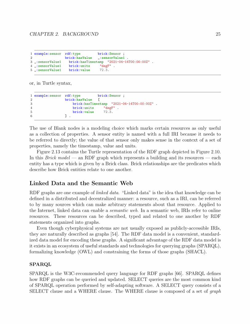
CHAPTER 2. BACKGROUND 25
1 example:sensor rdf:type brick:Sensor ;2 brick:hasValue _:sensorValue1 .3 _:sensorValue1 brick:hasTimestamp "2021-04-14T00:00:00Z" .4 _:sensorValue1 brick:units "degF" .5 _:sensorValue1 brick:value 72.3.
or, in Turtle syntax,
1 example:sensor rdf:type brick:Sensor ;2 brick:hasValue [3 brick:hasTimestamp "2021-04-14T00:00:00Z" .4 brick:units "degF" .5 brick:value 72.3.6 ] .
The use of Blank nodes is a modeling choice which marks certain resources as only usefulas a collection of properties. A sensor entity is named with a full IRI because it needs tobe referred to directly; the value of that sensor only makes sense in the context of a set ofproperties, namely the timestamp, value and units.
Figure 2.13 contains the Turtle representation of the RDF graph depicted in Figure 2.10.In this Brick model — an RDF graph which represents a building and its resources — eachentity has a type which is given by a Brick class. Brick relationships are the predicates whichdescribe how Brick entities relate to one another.
Linked Data and the Semantic Web
RDF graphs are one example of linked data. “Linked data” is the idea that knowledge can bedefined in a distributed and decentralized manner: a resource, such as a IRI, can be referredto by many sources which can make arbitrary statements about that resource. Applied tothe Internet, linked data can enable a semantic web. In a semantic web, IRIs refer to onlineresources. These resources can be described, typed and related to one another by RDFstatements organized into graphs.
Even though cyberphysical systems are not usually exposed as publicly-accessible IRIs,they are naturally described as graphs [54]. The RDF data model is a convenient, standard-ized data model for encoding these graphs. A significant advantage of the RDF data model isit exists in an ecosystem of useful standards and technologies for querying graphs (SPARQL),formalizing knowledge (OWL) and constraining the forms of those graphs (SHACL).
SPARQL
SPARQL is the W3C-recommended query language for RDF graphs [66]. SPARQL defineshow RDF graphs can be queried and updated. SELECT queries are the most common kindof SPARQL operation performed by self-adapting software. A SELECT query consists of aSELECT clause and a WHERE clause. The WHERE clause is composed of a set of graph

CHAPTER 2. BACKGROUND 26
1 @prefix bldg: <http://example.com/mybuilding#> .2 @prefix brick: <https://brickschema.org/schema/Brick#> .34 bldg:AHU1A a brick:Air_Handler_Unit ;5 brick:feeds bldg:VAV2-4,6 bldg:VAV2_3 .7
8 bldg:VAV2-3 a brick:Variable_Air_Volume_Box ;9 brick:feeds bldg:VAV2-3Zone .
10
11 bldg:Room-410 a brick:Room .12 bldg:Room-411 a brick:Room .13 bldg:Room-412 a brick:Room .14
15 bldg:VAV2-3Zone a brick:HVAC_Zone ;16 brick:hasPart bldg:Room-410,17 bldg:Room-411,18 bldg:Room-412 .19
20 bldg:VAV2-4 a brick:Variable_Air_Volume_Box ;21 brick:hasPart bldg:VAV2-4.DPR ;22 brick:hasPoint bldg:VAV2-4.SUPFLOW,23 bldg:VAV2-4.SUPFLSP .24
25 bldg:VAV2-4.DPR a brick:Damper ;26 brick:hasPoint bldg:VAV2-4.DPRPOS .27
28 bldg:VAV2-4.DPRPOS a brick:Damper_Position_Setpoint .29 bldg:VAV2-4.SUPFLOW a brick:Supply_Air_Flow_Sensor .30 bldg:VAV2-4.SUPFLSP a brick:Supply_Air_Flow_Setpoint .31 bldg:VAV2-4.ZN_T a brick:Supply_Air_Temperature_Sensor .
Figure 2.13: Example Turtle-formatted RDF graph for the Brick model depicted in Fig-ure 2.10
patterns. A basic graph pattern is a triple of subject, path expression, object. Subjectsand objects can be IRIs, Literals or variables. A path expression describes a route from thesubject to the object in terms of IRIs and variables. SPARQL 1.1 defines a family of pathoperators and expressions [66] which include sequence (path1 / path2), transitive closure(path1*), alternatives (path1 | path2) and optional paths (path1?).
The result of evaluating a graph pattern is a relation R (a set of n-ary tuples) whose nattributes are bindings of RDF graph terms to the variables in that clause. The . operatorbetween graph patterns is the conjunctive operator. A variable appearing in more than onegraph pattern amounts to a join between those two graph patterns. The result of executinga SPARQL query is a relation derived from the natural join of the intermediate relationsproduced by each of the graph patterns; this relation has a projection operator applied whichpreserves the variables contained in the SELECT clause. Figure 2.14 contains a SPARQLquery which retrieves the name of all VAVs in Figure 2.13 which have air flow sensors and air

CHAPTER 2. BACKGROUND 27
1 prefix rdf: <http://www.w3.org/1999/02/22-rdf-syntax-ns#>2 PREFIX rdfs: <http://www.w3.org/2000/01/rdf-schema#>3 PREFIX brick: <https://brickschema.org/schema/Brick#>4 SELECT ?vav ?sensor ?setpoint WHERE {5 ?vav rdf:type/rdfs:subClassOf* brick:VAV .6 ?vav brick:hasPoint ?sensor .7 ?vav brick:hasPoint ?setpoint .8 ?sensor rdf:type brick:Supply_Air_Flow_Sensor .9 ?setpoint rdf:type brick:Supply_Air_Flow_Setpoint .
10 }
Figure 2.14: Simple SPARQL query for the airflow setpoints and sensors associated withVAVs
flow setpoints, along with the names of those two points. The result of executing Figure 2.14on Figure 2.13 is a single tuple with the bindings:
• ?vav: http://example.com/mybuilding#VAV2-4
• ?sensor: http://example.com/mybuilding#VAV2-4.SUPFLOW
• ?setpoint: http://example.com/mybuilding#VAV2-4.SUPFLSP
Self-adapting software can use graph query languages like SPARQL to retrieve necessaryconfiguration data and other information from an RDF graph representing the semanticmetadata for a particular environment. This is closely examined in Chapter 5.
OWL
On their own, RDF graphs are just collections of statements with a well-defined syntaxand structure. In order to enable the consistent and interpretable exchange of information,the semantics or meaning of the data must be formally specified. An ontology is a way ofprogrammatically defining the meaning of data for a particular knowledge domain as a setof rules and axioms. The Web Ontology Language, or OWL, is a language for declarativelyexpressing those rules and axioms.
The rules and axioms expressible in OWL operate under the open world assumptionor OWA. Statements that are contained within a graph are true. Under the open worldassumption, statements that are not contained in the graph are simply unknown and cannotbe asserted as false. Its corollary, the closed world assumption or CWA, treats statementsnot in the graph as false; relational database systems operate under CWA. The OWA makessense in the context of the semantic web, where the absence of a statement in a particulargraph does not mean that another graph has made that statement. However, as explored inChapter 4, OWA presents challenges for cyberphysical systems when the full extent of thegraph can actually be known.

CHAPTER 2. BACKGROUND 28
There are two ways in which computable meaning can be attached to the statementsin an OWL ontology: OWL 2 DL and OWL 2 Full [74]. OWL 2 DL can compute mostof what OWL 2 Full can compute and is dramatically faster and simpler to compute thanOWL 2 Full. The “DL” indicates that OWL 2 DL is a description logic, which is a decidablebut less expressive subset of first-order logic. Chapter 4 establishes that only OWL 2 DL isrequired to implement the ontology features required for consistent and extensible semanticcyberphysical metadata. For this reason and the decidability and reduced computationalcomplexity of OWL 2 DL compared to OWL 2 Full, this thesis focuses on the former.Description logics make a distinction between the TBox and the ABox. The TBox, or“terminological box”, is the set of statements that define the ontology; this includes classstructures and relationships between concepts. The ABox, or “assertion box”, are the groundstatements or “facts” that populate the content of the model. There is no formal distinctionbetween TBox and ABox; these terms are used to differentiate between the statements thatdefine the ontology and the statements that define the model instance.
OWL 2 DL can be broken down into several profiles, or sublanguages, that define subsetsof OWL 2 DL that trade off computational complexity for expressive power in differentways [74]. The ontology features described in Chapter 4 require the OWL 2 RL profile: thisis a subset of OWL 2 DL that can be implemented in a rule-based language such as Datalog3.Chapters 4 and 7 delve into the OWL 2 RL rules used to express metadata and the systemsthat evaluate those rules, respectively.
SHACL
The Shapes Constraint Language (SHACL) is at its core a language for validating an RDFgraph against a set of conditions [81]. RDF graph validation allows a modeler to expresswhat the graph should and should not contain, depending on other properties of the graph.SHACL constraints can also helpfully emulate some features of CWA.
SHACL constraints are expressed as RDF triples and take the form of a set of shapes. Ashape is an entity with a target, a specification of the IRIs that it applies to, and a set ofparameterized constraints that describe predicates on that target. There are two kinds ofshapes: node shapes and property shapes. Node shapes specify constraints about the nodesof an RDF graph; property shapes specify constraints about the edge of an RDF graph.
Validating an RDF graph against a set of SHACL shapes generates a report which de-scribes whether or not the validation passed and, if not, which constraints were violated bywhich elements of the target graph. SHACL-AF [80] is an addendum to SHACL that addsreasoning and inference capabilities.
3a closed-world relational language

CHAPTER 2. BACKGROUND 29
2.5 Summary
The built environment spans the buildings, cities, power grids, transportation systems andother networked, physical components of the human experience. These cyberphysical com-ponents consist of a complex, interconnected array of devices, equipment, sensors and otherdata sources. Despite the existence of many possible digital representations of this infras-tructure, such representations do not capture the salient elements that support self-adaptingsoftware. Linked data specification languages such as RDF, OWL, SHACL and SPARQLprovide a means of specifying a formal representation of cyberphysical systems that can bereasoned about, validated and queried. These languages form the foundation of the proposedapproach to enabling self-adapting software.

30
Chapter 3
A Vision of Self-Adapting Software
Executing data-oriented cyberphysical software at scale is impractical because of the ef-fort required to customize the operation of each application to each deployment environment.This customization effort is manual and time-consuming due to the lack of structured meta-data about cyberphysical environments, and the lack of an effective method of customizingthe behavior of software.
Software needs to be customized because cyberphysical environments are heterogeneousand thus require bespoke treatment. The nature of the customization depends on the needsand complexity of the software. At minimum, the software needs to be configured with thedata sources it needs to read and where to read them from. This requires discovery of whichdata sources are relevant to the application. In current practice, data discovery is performed
Data
CPS Application
ReconfigurationReimplementation
Data
CPS Application
ReconfigurationReimplementation
Data
CPS Application
ReconfigurationReimplementation
Data
CPS Application
ReconfigurationReimplementation
Figure 3.1: Current practice: deploying software to different sites requires re-implementingand re-configuring the software for each site

CHAPTER 3. A VISION OF SELF-ADAPTING SOFTWARE 31
Data
Metadata
Self-Adapting Application
Discover Relevant Data
Configure App Logic
Automatic Configuration + Customization
Data
Metadata
Data
Metadata
Data
Metadata
Figure 3.2: Self-adapting software will query a metadata model of its environment in orderto automatically configure a single implementation to operate on new sites.
manually1 through inspection of BMS labels or other unstructured, human-oriented meta-data. Configuring more complex software may require additional context about what kindsof subsystems are in the environment and how those subsystems are composed and operated.Discovery of context is more time consuming and more error prone because this metadatais not usually captured in available representations. In most cases, each environment is sounique that configuring software requires a wholly new algorithm or implementation for thesoftware’s purpose to be achieved. Figure 3.1 describes the current state-of-the-art: for eachbuilding, a new implementation must be developed for each deployment environment. Thisapproach is impractical at scales larger than a handful of environments and is a significantbottleneck to the adoption of data-driven sustainable and energy efficiency practices.
Self-adapting software (Figure 3.2) is a new paradigm for programming cyberphysi-cal systems which eliminates the configuration and implementation bottleneck to deployingsoftware at large scales. By exploiting rich, descriptive semantic metadata about each envi-ronment, self-adapting software is able to discover enough about its deployment to configureitself automatically. This enables a new regime of “write once, run anywhere” software bymaking cyberphysical software become substantially easier to write and deploy. Lowering thebarrier to entry for adopting cyberphysical software also democratizes access to data-drivensustainable practices and energy efficiency measures that were previously cost-prohibitive todeploy at scale.
Addressing Challenges
Accomplishing this vision requires addressing a family of challenges; each of these is addressedin a chapter of this thesis.
Challenge #1: Describing Heterogeneous Settings: The success of self-adaptingsoftware for cyberphysical systems is contingent on the existence of a machine-readabledescription of the nature and context of the data sources and other resources in a given
1such as browsing through web interfaces, executing regular expressions over lists of points, and the like
CHAPTER 3. A VISION OF SELF-ADAPTING SOFTWARE 32
environment. This description must be able to describe enough of the environment that self-adapting software can perform the necessary discovery and configuration. However, existingmetadata representations are ill-suited for modeling the diversity and heterogeneity of cy-berphysical systems. This thesis proposes the use of a formalized graph model for metadatathat is flexible enough to represent many different kinds of cyberphysical environments. Eachcyberphysical environment will be represented by an RDF graph authored in Brick whichcaptures the data sources and their associated context. The semantics and structure of thegraph will be informed by a formal OWL-based ontology which defines the concepts, axiomsand relationships required to describe cyberphysical environments. Doing this effectively re-quires new ontology design patterns which enforce interpretability and modeling consistencyof the metadata graph while enabling extensibility of the ontology design. Chapter 4 reviewsshortcomings of existing metadata representations for cyberphysical systems and identifiesfundamental flaws in popular tag-based metadata designs. It then proposes and implementsa set of new ontology design patterns and features which advance the applicability of se-mantic web technologies for complex cyberphysical systems. These novel design patterns areevaluated in the context of Brick, a metadata ontology for data-driven smart buildings.
Challenge #2: Designing an Effective Programming Model: Self-adapting soft-ware must have a means of exploiting the semantic metadata representing each environmentin order to configure itself. How should such software be expressed? Specifically, how shouldself-adapting software access the metadata model for an environment and implement theirapplication logic in terms of the content of that model? The metadata model adheres tothe standard RDF data model, so it is possible for self-adapting software to use existingquery languages and technologies like SPARQL for discovering and accessing the metadatamodel. However, a query language alone is insufficient to enable self-adapting software.Chapter 5 explores the design of two different programming models that provide first-classsupport for semantic metadata within a Python-based programming framework. The firstmodel decomposes application logic into set of stages which progressively abstract away het-erogeneity between environments, allowing the core application logic to be expressed in anenvironment-agnostic manner. This provides a modular, batch-style approach to construct-ing portable software: query and data cleaning and analytics components (or “stages”) canbe reused or repurposed with minimal reconfiguration. The second model explores an imper-ative abstraction of SPARQL queries that is more appropriate for interactive and exploratoryprogramming.
Challenge #3: Metadata Management Over Time: Cyberphysical environmentsinevitably evolve over time. These changes may be in response to a variety of stimuli, includ-ing decay (parts of the environment breaking), repairs and retrofits (replacing or augmentingparts of the environment), Semantic metadata models must be kept up-to-date with theircyberphysical counterparts in order for self-adapting software to execute correctly and con-tinuously. This thesis proposes a metadata management system that can detect changesin the environment and use those changes to bootstrap edits to the metadata model. Thesystem can also handle changes to the semantics of the model itself which may occur as theunderlying ontology evolves and expands. Addressing these challenges requires the devel-

CHAPTER 3. A VISION OF SELF-ADAPTING SOFTWARE 33
opment of new semantic data integration techniques. Prior work on database migrationsprovides mechanical techniques for how changes can be incorporated into the model, butdoes not ensure that these changes are semantically valid. The data integration literatureestablishes techniques for extracting structured data from heterogeneous information sourcesbut does not address how different extracted data can be merged into a single, semanticallyvalid model. Chapter 6 develops and formalizes a system that addresses the shortcomingsof existing techniques which arise in their application to cyberphysical environments andmetadata.
Challenge #4: Metadata Management at Scale: A final challenge with enablingand supporting self-adapting software is how to design and implement the platforms thatstore, query and manipulate the semantic metadata. Existing platforms for semantic-webdata are largely designed for batch processing on large graphs (on the order of millions orbillions of nodes and edges); most are positioned as knowledge bases and information refer-ences rather than platforms for large volumes of interactive applications. Most research inRDF databases has focused on efficient storage and query processing as a result. However,the ontology features that that make semantic metadata suitable for self-adapting softwarerequire support for performant reasoning and inference. Furthermore, existing platformsdo not implement features for integrating semantic metadata with historical telemetry orinterfaces for cyberphysical control. Chapter 7 presents the architectures and implementa-tions of two real-world systems that address these gaps in RDF database design. The first,Mortar, is an analytics platform with an integrated timeseries database and RDF databasethat provides a declarative API for programming and executing self-adapting applicationsusing the staged execution model. This platform is augmented by reasonable, a performantOWL-RL reasoner that augments semantic metadata models with inferred information andimplements the required ontology features.
Architecture
Figure 3.3 outlines how this vision of self-adapting software can be realized. Cyberphysicalsystems — including but not limited to buildings, cities, water treatment and smart grids— produce data by means of an increasing numbers of sensors and other digital sources, andare represented by a diverse family of structured and unstructured metadata sources. Thisthesis proposes a semantic and structural lifting of these sources into a formal graph-basedmodel as typified by Brick. This model contains descriptive metadata which captures thecomposition and structure of cyberphysical systems in an environment as well as the datasources and command points which track the behavior of the environment over time.
The metadata model for each environment can be bootstrapped and maintained througha metadata integration process which extracts and combines semantic metadata from avail-able digital representations. A self-adapting software platform manages the content of themetadata model over time, including the evaluation of inference rules and validation ofthe model with respect to logical axioms defined by a formal ontology. This ensures that
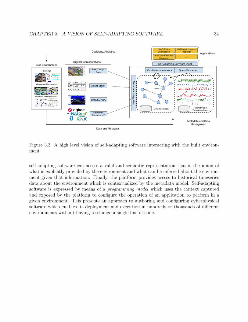
CHAPTER 3. A VISION OF SELF-ADAPTING SOFTWARE 34
Buildings
Wastewater Management
Smart Grid and Renewables
Built Environment
BIM / Design Docs
Asset Mgmt
BMS/SCADA
HVAC Control Optimization
Networked Devices + IoT
Digital Representations
Metadata Integration
Metadata and Data Management
Continuous Inference
Building Occupancy Prediction
Fault Detection and Diagnosis ...
Decisions, Analytics
Data and Metadata
Metadata Graph Telemetry and Timeseries Data
Query Processor
Applications
Self-Adapting Software Stack
Figure 3.3: A high level vision of self-adapting software interacting with the built environ-ment
self-adapting software can access a valid and semantic representation that is the union ofwhat is explicitly provided by the environment and what can be inferred about the environ-ment given that information. Finally, the platform provides access to historical timeseriesdata about the environment which is contextualized by the metadata model. Self-adaptingsoftware is expressed by means of a programming model which uses the context capturedand exposed by the platform to configure the operation of an application to perform in agiven environment. This presents an approach to authoring and configuring cyberphysicalsoftware which enables its deployment and execution in hundreds or thousands of differentenvironments without having to change a single line of code.

35
Chapter 4
Managing Heterogeneity withSemantic Metadata
We are tied down to a languagewhich makes up in obscuritywhat it lacks in style.
Tom Stoppard, Rosencrantz andGuildenstern are Dead
A fundamental challenge to enabling self-adapting software is dealing with the intrinsicheterogeneity of the cyberphysical systems being controlled and analyzed. When every site,building and system differs both in the nature of its construction and in how it is described,there is often little choice but to undertake the manual, time-consuming and error-proneprocess of rewriting and reconfiguring software for each intended deployment. Prior workestablishes that rich, descriptive metadata is crucial to reducing and even automating thiseffort [16, 15, 84, 25, 54]. Self-adapting software queries metadata in order to configureits operation to the particulars of a given deployment. This includes the discovery of datasources and their context as well as the determination of which algorithms are appropriate.
Doing this effectively requires a careful balance of potentially conflicting design principles.An effective metadata representation for self-adapting software must be general enough torepresent many different kinds of cyberphysical systems while capturing enough specificdetail to support the complex requirements of software. The representation should model anappropriate level of abstraction that permits automated reasoning about the composition andfunction of cyberphysical systems. This chapter explores the design and use of a semanticmetadata ontology for cyberphysical systems which effectively manages heterogeneity inorder to support self-adapting applications.

CHAPTER 4. MANAGING HETEROGENEITY WITH SEMANTIC METADATA 36
Metadata Design Principles
Established metadata representations and standards (Chapter 2) do not capture the in-formation required to support real-world cyberphysical applications [26]. To address theseshortcomings, the Brick ontology, developed in 2016, established three design goals to guidethe design of effective building metadata for such applications [16]:
• Completeness: Can the metadata representation define the concepts, types and en-tities that exist in buildings and are required by canonical energy-, operations- andmanagement-related applications?
• Expressiveness: Can the metadata representation define the important relation-ships between entities that exist in buildings and are required by canonical energy-,operations- and management-related applications?
• Usability: Can the metadata be presented in a form that supports the developmentof applications through integration with existing data analysis frameworks and tools?
These three design goals inform an empirical approach to the design of a metadata rep-resentation. The set of equipment, location and point concepts defined in Brick are sourcedfrom the BMS labels for six large college campus office and laboratory buildings [16]. The setof Brick relationships are sourced from a systematic study of over 90 building applications [26]Together, these two sources make Brick both complete and expressive. A representative setof building analytics applications, drawn from the literature, was implemented using queriesagainst Brick models for the six reference buildings; the success of this initial study indicatesthat Brick is also usable.
This chapter argues that these principles, although successful, are not sufficient for man-aging heterogeneity at large scale. In particular, a metadata representation must also pro-mote
• Interpretability: The intended meaning of the metadata in the model should beunambiguous and defined programmatically. If there is more than one interpretationof a part of the metadata model, software will not be able to reliably identify andcontextualize the data it needs to operate.
• Consistency: The structure and composition of metadata models for cyberphysicalsystems should depend more on the level of detail and completeness necessary forapplications, rather than on the opinions and philosophies of the modeler. Similarcyberphysical systems should be described in a similar manner. Two individuals de-scribing the same cyberphysical system should produce similar, or at least compatible,metadata models.
• Extensibility: The metadata representation should support the structured exten-sion of the concepts and relationships defined within in a consistent and interpretablemanner

CHAPTER 4. MANAGING HETEROGENEITY WITH SEMANTIC METADATA 37
The rest of this chapter will review the issues and design limitations of existing metadatarepresentations for cyberphysical systems in the context of the design goals outlined above, inparticular, linked data ontologies and tag-based metadata as typified by Project Haystack. Asystematic study of the consistency, interpretability and extensibility issues of the Haystackmetadata representation is performed. A review of the limitations and issues incumbent inthe Brick ontology is also conducted. The resulting discussion explores how these issues aredue to a lack of formal axioms. This motivates the design and implementation of Brick+,a formalization and extension of Brick that combines the “tag-based” benefits of Haystackwith the “class-based” benefits of Brick.1
4.1 Limitations of Existing Metadata Representations
Despite the large number of metadata representations available in the IoT and smart buildingdomains, they largely do not address the needs of self-adapting software.
Consumer-facing IoT Platforms
IoT software platforms define APIs and libraries that directly support executing software oncyberphysical systems. The metadata aspects of these platforms focus on service discoveryand descriptions of device functionality that can be accessed via APIs. Descriptions of devicefunctionality typically involve structured documents containing well-known service names,with implementation and access details available as standardized parameters. This is seenin designs like Ninja [36], Universal Plug-and-Play, and mDNS [31].
Another approach, commonly referred to as “the web of things”, uses linked data andother web standards to describe and provide access to device functionality [160]. The mostmature effort is the ontology produced by the W3C Web of Things working group [155],which standardizes the representation of Thing Descriptions. Thing Descriptions representthe set of supported interactions for a device using a small vocabulary that captures thestructure of data that is input and output to the device. Because these descriptions arebuilt on RDF they can — and are expected to — leverage external ontologies for semanticdescriptions of what the interactions actually are.
However, a fundamental limitation of these digital representations is that they leave out,or fail to standardize, contextual information about where devices are, how they are installedand how they interact with their environment and each other. Service discovery frameworksare designed to enable access to remote services, regardless of location; the focus is on whatfunctionality those services provide. Likewise, consumer IoT platforms largely target smalldeployments in typically residential settings: devices with straightforward functionality inrelatively homogeneous settings do not have a need for complex contextual metadata. As a
1The distinction between Brick+ and Brick is done solely to differentiate what work has been done as apart of this thesis. Brick+ has been merged into Brick versions 1.1 and 1.2.

CHAPTER 4. MANAGING HETEROGENEITY WITH SEMANTIC METADATA 38
result, these standards and platforms have a limited ability to support the richer metadatafor the heterogeneous settings typical of large buildings and complex cyberphysical systems.
Building Information Modeling
Building Information Modeling (BIM) technologies — including gbXML [60], IFC [1] andRevit [11] — are designed to enable the exchange of information between different teamsduring the design and construction of a building. As a result, the data model must be flexibleand extensible enough to capture precise definitions of geometry, mechanical, electrical andplumbing infrastructure [12]. The Industry Foundation Classes standard contains hundredsof concepts and properties describing furniture, HVAC, lighting and other kinds of physicalequipment, in addition to the segments, fittings and connectors constituting the distributionsystems for different substances in the building [1].
The resulting complexity of these models makes them difficult to maintain and use forother stages of the building lifecycle, which require different kinds of details to be cap-tured [139]. In particular, the flexibility provided by BIM data models presents challengesfor the consistent and interpretable exchange of BIM data because the extensions made “inthe field” by the teams designing and constructing buildings do not extend the BIM in thesame way. This lack of interoperability has real costs: the National Institute of Standardsand Technology published a report in 2004 estimating the cost of inadequate interoperabilitywithin the property, construction and facility management industry to be $15.8 billion peryear [57].
The interoperability issues with BIM accentuate the need for a data model to be extensiblein a consistent manner, so that the resulting representations are easily and automaticallyinterpretable. This begins with defining a data model that is complete and expressive enoughthat the necessary concepts can be defined.
Upper Ontologies for IoT
Issues of structural interoperability — the ability of two or more systems to exchange infor-mation — and semantic interoperability — the ability of two or more systems to exchangeinformation with a consistent and interpretable meaning — have long been the subject ofstudy in linked data and semantic web communities. The RDF data model, with its manyserialization formats such as Turtle [18], RDF/XML [17] and more recently JSON-LD [134],enables a structural interoperability between data sources: triples are triples, and they canbe easily stored and queried.
Ontology design, in particular the design of upper ontologies, intends to solve issues ofsemantic interoperability. Upper ontologies attempt to define a common family of genericconcepts and axioms that are common to many (if not all) domains, and can therefore enablesemantic interoperability. Domain-specific ontologies can “anchor” their own concepts andproperties to those provided by an upper ontology. Ontologies based on the same upperontology can then interpret each other’s contents in terms of that upper ontology.
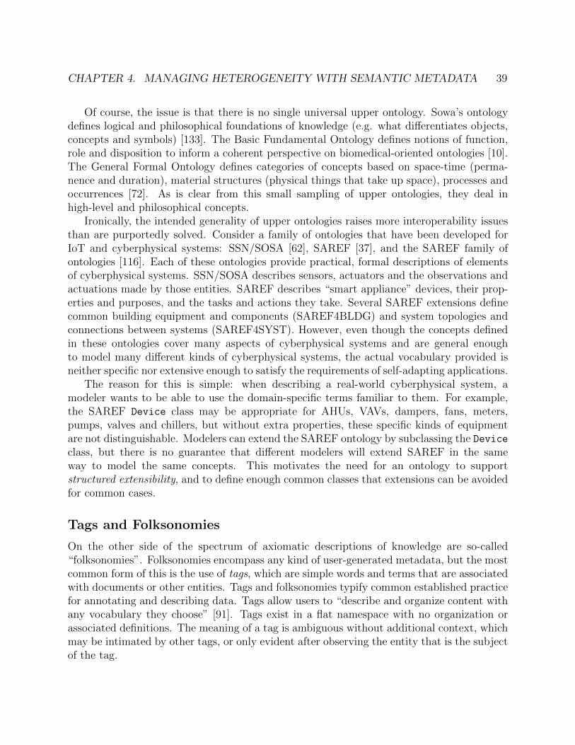
CHAPTER 4. MANAGING HETEROGENEITY WITH SEMANTIC METADATA 39
Of course, the issue is that there is no single universal upper ontology. Sowa’s ontologydefines logical and philosophical foundations of knowledge (e.g. what differentiates objects,concepts and symbols) [133]. The Basic Fundamental Ontology defines notions of function,role and disposition to inform a coherent perspective on biomedical-oriented ontologies [10].The General Formal Ontology defines categories of concepts based on space-time (perma-nence and duration), material structures (physical things that take up space), processes andoccurrences [72]. As is clear from this small sampling of upper ontologies, they deal inhigh-level and philosophical concepts.
Ironically, the intended generality of upper ontologies raises more interoperability issuesthan are purportedly solved. Consider a family of ontologies that have been developed forIoT and cyberphysical systems: SSN/SOSA [62], SAREF [37], and the SAREF family ofontologies [116]. Each of these ontologies provide practical, formal descriptions of elementsof cyberphysical systems. SSN/SOSA describes sensors, actuators and the observations andactuations made by those entities. SAREF describes “smart appliance” devices, their prop-erties and purposes, and the tasks and actions they take. Several SAREF extensions definecommon building equipment and components (SAREF4BLDG) and system topologies andconnections between systems (SAREF4SYST). However, even though the concepts definedin these ontologies cover many aspects of cyberphysical systems and are general enoughto model many different kinds of cyberphysical systems, the actual vocabulary provided isneither specific nor extensive enough to satisfy the requirements of self-adapting applications.
The reason for this is simple: when describing a real-world cyberphysical system, amodeler wants to be able to use the domain-specific terms familiar to them. For example,the SAREF Device class may be appropriate for AHUs, VAVs, dampers, fans, meters,pumps, valves and chillers, but without extra properties, these specific kinds of equipmentare not distinguishable. Modelers can extend the SAREF ontology by subclassing the Deviceclass, but there is no guarantee that different modelers will extend SAREF in the sameway to model the same concepts. This motivates the need for an ontology to supportstructured extensibility, and to define enough common classes that extensions can be avoidedfor common cases.
Tags and Folksonomies
On the other side of the spectrum of axiomatic descriptions of knowledge are so-called“folksonomies”. Folksonomies encompass any kind of user-generated metadata, but the mostcommon form of this is the use of tags, which are simple words and terms that are associatedwith documents or other entities. Tags and folksonomies typify common established practicefor annotating and describing data. Tags allow users to “describe and organize content withany vocabulary they choose” [91]. Tags exist in a flat namespace with no organization orassociated definitions. The meaning of a tag is ambiguous without additional context, whichmay be intimated by other tags, or only evident after observing the entity that is the subjectof the tag.

CHAPTER 4. MANAGING HETEROGENEITY WITH SEMANTIC METADATA 40
The main benefit of tags are their flexibility and low barrier to entry [91]; there is noneed to learn relatively esoteric logic languages and familiarize oneself with the philosophicalunderpinnings of an upper ontology. The social bookmarking site del.icio.us and thephoto sharing site Flickr were largely successful due to their adoption of user-generated tagsto describe the content described by users. More recent examples of successful tag-basedproducts include Instagram and Twitter, which use “hashtags” as a form of tagging. Aftertagging an entity such as a post or photo with a tag, users can find other content with thesame tag. This content may not use the tag in the same way, but the intent is to sharecontent, not to communicate its meaning in an unambiguous manner.
Project Haystack [118] adopts a similar folksonomic approach to metadata in buildings.The equipment, points and other entities in a Haystack model of a building are describedwith sets of tags. Haystack defines a dictionary of common tags which are available to users,but also allows users to define their own tags. The result is a data model that is flexible andextensible but also does not enable the consistent, interpretable and interoperable exchangeof building metadata.
Relational Schemas
Although cyberphysical metadata is fundamentally graph-oriented, it is possible to expressmost features of the metadata in a relational form. However, the heterogeneous and inter-connected nature of cyberphysical metadata makes the relational model a poor fit.
Relational tables can represent names and properties of the entities in the environment.More than one table may be required to represent different types of entities: the propertiesof a temperature sensor entity will be different than the properties of a pump equipmententity. Variability in which properties are available for each entity may result in wide andsparse tables because the schema must represent all possible properties for an entity, even ifa given entity does not have those properties. Foreign keys, one-to-many and many-to-manytables can all be used to represent the relationships between entities.
While it is possible to author a relational schema for a particular environment, developingan efficient schema requires prior knowledge of the kinds of entities in the environment, theirproperties, and the relationships. Generalizing the relational schema to other environmentsrequires denormalization of the schema. Denormalized schemas like entity-attribute-valuetables are essentially a representation of RDF’s subject-predicate-object triple. Recursivequeries are required in order for denormalized schemas to support the required query featuresfor traversing the graph structure of the metadata; this includes path queries and transitiveclosures. For these reasons, a single relational schema would be a poor fit to model hetero-geneous and complex cyberphysical systems. Developing a unique relational schema for eachcyberphysical environment is only a partial solution, because software would still have to berewritten for each environment.

CHAPTER 4. MANAGING HETEROGENEITY WITH SEMANTIC METADATA 41
4.2 Modeling Issues for Tag-Based Metadata
The tag-based Haystack metadata model has several intrinsic issues that fundamentallylimit the semantic interoperability of the data it describes: designing for flexibility at thecost of consistency, a lack of a formal specification, and inconsistent and ill-defined modelingpractices.
Balancing Composability and Consistency
The design of Haystack prioritizes familiarity, composability and flexibility over consistencyand interpretability. This is one of the key benefits of a tag-based metadata scheme [91].However, this flexibility hampers the ability of an arbitrary consumer of tags to consistentlyinterpret how a specific combination of tags is intended. In tag-based metadata schemes,increased composability comes at the cost of lower consistency. Specifically, without formalrules defining the meaning of groups of tags and how tags may be composed, the interpreta-tion of a tag set is dependent upon idiom, convention and other “common knowledge” of thegroup or individual who chose the tag set. As a result, the tag set chosen by one individualto describe an entity may have multiple possible subtly different meanings, or no meaningat all, to other individuals.
Haystack provides a dictionary of tags with community-provided definitions; these defi-nitions are intended to make it clear when a modeler should choose one tag over the other.However, the tag definitions often include caveats and describe idioms, which complicate tagusage. For example, the Haystack definition of the air tag points out that the use of thetag implies a dry bulb temperature measurement unless otherwise specified:
“Point associated with the measurement or control of air. In regards to wetBulb,points with the air tag are associated with dry bulb.[122]”
The root of the semantic ambiguity is the fact that tags can be used in different contexts.Even if a tag has a specific definition (such as air), the use of a tag does not communicatehow the tag’s concept relates to the other tags associated with a given entity. For example,the heat and oil tag together do not indicate if oil is being heated, or if hot oil is doingthe heating of some other substance. Haystack identifies this kind of issue as a “semanticconflict”:
“Another consideration is semantic conflicts. Many of the primary entity tagscarry very specific semantics. For example the site tag by its presence meansthe data models a geographic site. So we cannot reuse the site tag to meansomething associated with a site; which is why use the camel case tag siteMeter
to mean the main meter associated with a site.[119]”To mitigate this issue, Haystack introduces compound tags (called “camel case tags”
above), which are concatenations of existing tags into new atomic tags with specific and dis-tinct meanings from the tags from which they are composed. This reduces the composabilityof the tagging scheme, as tags now only have well-defined meanings in specific contexts andcannot be arbitrarily combined.

CHAPTER 4. MANAGING HETEROGENEITY WITH SEMANTIC METADATA 42
Tag Des
c.equip
Des
c.point
Des
c.m
echan
ism
For
AH
U
For
VA
V
For
Coi
l
For
Val
ve
For
Chille
r
For
Boi
ler
hea
ting
heat X X X Xheating XhotWaterHeat X X XgasHeat X X XelecHeat X X XsteamHeat X X XperimeterHeat X X
rehea
ting reheat X X
reheating X XhotWaterReheat X X XelecReheat X X X
cool
ing
cool X X X Xcooling XcoolOnly X XdxCool X X XchilledWaterCool X X XwaterCooled X XairCooled X X
Table 4.1: An enumeration of the intended use and context of tags relating to heating andcooling, as given by the Haystack documentation. Note the differences in diction acrosscompound tags, and how some compound tags could be assembled from more atomic tags.Some tags are used both for equipment and for points when equipment is modeled as a singlepoint (such as VFDs, Fans, Coils)
As an illustrative example, consider the hotWaterHeat compound tag: Haystack definesthis tag as an annotation on an air handling unit that has a hot water-based heating ca-pability. Unintuitively, this annotation does not use the heat, hot, water or air tags. Inthis way, the need to bring consistency to tags comes impedes their use as a flexible andpermissive annotation feature: the hot, water, heat and air tags applied to an air handlingunit may refer to many different aspects of its functionality.
Table 4.1 contains the results of a survey of defined Haystack tags that contain the word“heat” or “cool”. Each of the tags in the table is defined in the Haystack dictionary, andeach have a unique and thus nonfungible definition. The first three columns of the table

CHAPTER 4. MANAGING HETEROGENEITY WITH SEMANTIC METADATA 43
capture the contexts in which each tag has meaning:
• Describes equip : if this column is checked, then the tag describes equipment, oftenby what function it performs. For example, the gasHeat tag indicates that the relatedequipment consumes gas to perform some heating process.
• Describes point : if this column is checked, then the tag describes the context of adata stream (point). For example, the reheat tag describes data about the reheatingcapability of a VAV.
• Describes mechanism: if this columns is checked, then the tag communicates how acertain process or function is performed. For example, the gasHeat tag describes thenature of the heating process.
The last six columns of the table indicate if the tag is specifically for use with only onekind of equipment. The resulting tagging scheme is often unintuitive: the heat tag wouldseem to relate to a heating process, but it is in fact intended only for heating coils thatoccur in AHU and VAV equipment. Further, the tag definitions are simple text: there areno formal or standardized rules for communicating how they are intended be used or notused.
These issues are compounded by the fact that the Haystack query model does not supportstring matching operations, meaning that tags can only be matched by equality. This makesit difficult to use generic tags as a way of searching for relevant or similar entities [91], forinstance, a query for all entities that have a tag containing the word "heat".
Most of the ambiguities exposed above can be tracked to confusion as to what aspect orprocess of an entity a tag relates to. To address this issue, tags must either have meaningindependent of context, which is the direction that most tag-based metadata systems takebut also provides the least consistency, or a way of communicating the intended context2.Because the Haystack data model is so simple — unnested key-value documents with aunique identifier — there is no mechanism to easily communicate the intended use of atag (recall the dilemma “is oil being heated, or is it doing the heating?”). This forcesHaystack into the other model in which tags must have concrete meanings that require noadditional context to interpret correctly; however, this increases the size of the tag dictionary,complicates usage, and limits the composability of the tags in the dictionary. The rest ofthis chapter will explore how composability and consistency can be balanced through theuse of a formal data model.
Formalizing Tag Composition
Haystack lacks rules to formalize how tags may or may not be composed. This raises twoissues for semantic interoperability. First, arbitrary combinations of tags may not havea consistent interpretation, which hampers Haystack’s ability to provide an effective and
2This is called reification and it will be discussed in-depth in the next section.

CHAPTER 4. MANAGING HETEROGENEITY WITH SEMANTIC METADATA 44
standardized description of data. Ultimately, this makes well-known concepts harder tocommunicate consistently, and makes it difficult to figure out what the proper descriptionsare. Second, the use of tags to communicate the type of an entity can result in a classorganization that is not well-formed.
These issues are examined through an OWL-like treatment of classes and entities: allentities of the same type (i.e. belonging to the same class) are members of the same set. Asubclass is a set that is a subset of its superclass; the entities in the subclass must belong tothe superclass, but not all entities in the superclass are necessarily members of the subclass.A set of classes and the subclass relationships between them form a directed graph called aclass organization. A class organization is well-formed if it meets two conditions:
1. Acyclic: no class should be a superclass of itself.
2. Consistent semantics: if one class is a subclass of another, then it should be a morespecific concept than its superclass
A well-formed class organization is essential for the creation of consistent metadata mod-els because it facilitates the automated discovery of classes. In order to discover what classesare available and to determine which is the most appropriate for a given entity, a user canbrowse the class organization from the topmost superclasses (equipment, locations, sensors,etc) and follow the subclass links to find more specific versions of those classes. Without awell-formed class organization, the traversal cannot take advantage of the expected “generalto specific” organization in the class organization. A well-formed class organization is alsoextensible: users can create new, more specific classes that are subclasses of existing andmore general superclasses. Even in the absence of a textual definition for this new class, thesubclass relationship provides an immediate contextual scoping for how the class is meantto be used; this follows from the second condition for a well-formed class organization.
In the Haystack metadata model, the type or class of an entity is indicated by its tagset — the marker tags are associated with the entity. Formally, the tag set of an entity e isgiven by T (e). A class C is defined as a set of tags given by T (C). A class Cb is a subclassof Ca if T (Ca) ⊆ T (Cb). An entity e is an instance of class C if T (e) ⊆ T (C). If an entitye is an instance of class Cb and Cb is a subclass of Ca, then e is necessarily an instance ofboth Cb and Ca.
This formalism reveals how the use of tag sets to communicate the type of an entity isinsufficient for defining a well-formed class hierarchy in two ways: tags imply the existenceof classes that have no consistent or discernible meaning, and the resulting hierarchy maynot have consistent semantics.
To the first point, consider the set of tags sensor, temp, discharge and air. There are
15 =4∑
n=1
(4
n
)

CHAPTER 4. MANAGING HETEROGENEITY WITH SEMANTIC METADATA 45
sensor
temp sensor air sensor discharge sensor
discharge air sensor
discharge air temp sensor
discharge air temp
discharge temp sensor
temp airdischarge
air temp sensor
Figure 4.1: The set of valid (blue + solid outline) and invalid (red + dashed outline) tagsetsfor a set of four tags. The class hierarchy is established from top to bottom;subclass rela-tionships are indicated by arrows
combinations of tags possible from that dictionary. Figure 4.1 contains 12 of these. However,of these 15 tags, only 4 of them have an interpretation that makes sense in the building HVACdomain (along the left side).
To the second point, it is possible to construct two class definitions Ci and Cj such thatT (Ci) ⊆ T (Cj) but the definition of Ci is disjoint from Cj. Consider two concepts: Air Flow
Setpoint (the desired cubic feet per minute of air flow) and Max Air Flow Setpoint (themaximum allowed air flow setpoint). In Haystack, Air Flow Setpoint would be identifiedby the air, flow and sp tags, and Max Air Flow Setpoint would be identified by the air,flow, sp and max tags. Although the tags of Air Flow Setpoint are a subset of the Max Air
Flow Setpoint class, Air Flow Setpoint is not a superclass of Max Air Flow Setpoint:the former is a setpoint, but the latter is actually a parameter governing the selection ofsetpoints and therefore belongs to a distinct subhierarchy.
To circumvent this issue, rules for defining valid tagsets for subclass relationships mustbe defined in terms of which tags can be added to a given tag set to produce a valid subclassrelationship. Defining a concept requires knowing which tags cannot be added; withouta clear set of rules for validation, a user may use the max and min tags to indicate theupper/lower bounds of deadband-based control, which is inconsistent with the intendedusage of these tags. Haystack defines a few rules for extending existing concepts with newtags. Two examples from many:

CHAPTER 4. MANAGING HETEROGENEITY WITH SEMANTIC METADATA 46
1. AHU entities can be further characterized by their heating method, given by one ofgasHeat, hotWaterHeat, steamHeat or gasHeat.
2. Water meter entities can be further differentiated by the tags domestic, chilled,condenser, hot, makeup, blowdown and condensate.
In most cases, however, knowledge of which tags may be appropriate to add to an entitylargely depends upon domain familiarity and informal conventions. For example, Haystackpoint entities (sensors, setpoints and commands) often have a “what” tag (e.g. air), a“measurement” tag (e.g. flow) and a “where” tag (e.g. discharge). However, this is nota hard and fast rule, and many of the tag sets in Haystack’s documentation break with thisconvention. Consequently, there is no clear notion of how concepts can be meaningfullyextended or generalized, which limits the extensibility of Haystack.
Inconsistent Modeling Practices
Due to the lack of formal tag composition mechanisms and a well-formed class organization,there is substantial variance in how users of Haystack model the same concept. Theseinconsistent modeling practices limit the semantic interoperability of the Haystack model.
The most common source of modeling inconsistency is the choice of whether to modelpumps and fans as equipment or as points. Although pumps and fans are equipment, inmany BMS they are represented by only a single point (usually the speed or power level).Haystack’s documentation encourages simplifying the representation of such equipment un-der such circumstances:
“Pumps may optionally be defined as either an equip or a point. If thepump is a [variable frequency drive] then it is recommended to make it an equip
level entity. However if the pump is modeled [in the BMS as] a simple on/offpoint as a component within a large piece of equipment such as a boiler then itis modeled as just a point.[120]”
However, not all modelers in Haystack choose to make this simplification, especially whenthere are more points that may relate to the same equipment entity. To query a Haystackmodel in a consistent way, a user must write complex predicates that take into account thefamily of possible modeling choices.
Impact of Tags on Metadata Design
These issues with tag-based metadata inhibit extensibility and consistency at scale. MostHaystack models are designed to be used by small teams familiar with the site or sites athand, so it is enough for these models to be self-consistent. As long as there is agreement onhow to tag a given concept, the informality of the model is not as detrimental; most tag setsin Haystack make intuitive sense to domain experts. However, the lack of formalization —specifically, a lack of a formal class hierarchy and rules for composability and extensibility

CHAPTER 4. MANAGING HETEROGENEITY WITH SEMANTIC METADATA 47
— presents issues for adoption as an industrial standard and basis for automated analysisand reasoning.
The next 2 sections show that the tradeoff between composability and consistency is tiedto the choice to use tags for annotation as well as definition. With an explicit and formalclass hierarchy it is possible to design a system that exhibits the composability of simpletags, while retaining the consistency and extensibility of an ontology.
4.3 Ontology Design for Consistent Metadata
This chapter introduces the design and implementation of Brick+, a mostly3 backwards-compatible edition of the Brick ontology that is built on formal composition rules to achievedesirable properties of tag-based metadata while also improving upon the original Brickdesign [16, 15]. The heterogeneity of real-world deployments — including systems composedin unusual ways or containing novel or legacy equipment — and the innovation in the buildingindustry mean that extensions to the Brick ontology are a continuous necessity. Experienceswith the original Brick design revealed that simply providing a class organization, even withtextual descriptions, is not sufficient to ensure consistent extensions of the ontology.
Brick+ improves on the original Brick design through the incorporation of the followingfeatures:
• Semantic Class Lattice: classes in Brick+ are not just named sets like in many OWL-based ontologies. Instead, their definitions are qualified by a number of composablesemantic properties. The result is a lattice of classes that provides more structure toBrick extensions than a simple hierarchy.
• Compatibility between tags and classes: Brick+ incorporates Haystack-style tags asdefinition-free annotations on Brick entities. Entities inherit tags from the classes theyinstantiate; the implementation also supports the inference of a Brick class from acollection of tags. This can be done using both an exact and an approximate matchingalgorithm.
• Validation and tooling support: Brick+ defines constraints that enable the automaticvalidation of Brick models, and contains additional annotations that inform externaltooling that assists in the development and validation of Brick models.
The implementation of these features requires careful appliation of two different modelinglanguages — OWL RL and SHACL — and the invention of several design patterns. Brick+has been fully implemented and adopted as the authoritative Brick implementation at timeof writing4. The intuition and formal design of each of these features is presented below,followed by an overview of their implementation using semantic web modeling languages.
3A few mechanical and easily automatable changes must be made to existing Brick models.4Brick+ features have been released in Brick versions 1.1 and 1.2.

CHAPTER 4. MANAGING HETEROGENEITY WITH SEMANTIC METADATA 48
Point
Sensor
Temperature Sensor
Air Temperature Sensor
Supply Air Temperature
Sensor
Figure 4.2: An OWL-based ontology (right) encodes classes as named sets (left); a subclassrelationship between two classes means that all the members/instances of the subclass arealso members/instances of the superclass.
Semantic Class Lattice
OWL-based ontologies are typically built from classes related to each other through a sub-class relationship (Figure 4.2) — rdfs:subClassOf. Classes are named sets, but may haveother properties associated with them. For example, the skos:definition property fromthe Simple Knowledge Organization System ontology is a common choice for relating a classdeclaration to a text-based human-readable definition; alternatively, the rdfs:seeAlso prop-erty might point an interested user at a citation or other related resource.
However, these additional properties do not capture the semantics of the class in amachine-interpretable manner. Further, the subclass relationship only indicates membersof one class are a subset of the members of another class. It does not capture what distin-guishes the members of the subclass from the members of the superclass. Without the abilityto capture this information, it is difficult to ensure that extensions to the class organizationwill be done in a compatible manner. Modelers may choose a different class name for thesame concept, and thus ruin any interoperability between models produced using differentextensions. Even though a formalized and well-formed class organization addresses the am-biguities and inconsistencies inherent to the Haystack design, it is not enough to guaranteesemantic interoperability as an ontology is extended.
A semantic class lattice addresses this issue by removing the requirement that extensionsto the class hierarchy must use the same name for the same concept. This is accomplished byaugmenting the subclass relationship with additional semantic information which capturesthe distinguishing characteristics between two classes connected by a subclass relationship.This semantic information is composable — different combinations of semantic properties

CHAPTER 4. MANAGING HETEROGENEITY WITH SEMANTIC METADATA 49
indicate different concepts. The composition rules determining which semantic propertieshave semantic meaning is implicitly defined by the class organization. This means that theset of valid compositions of semantic properties are exactly those that have been explicitlyequated to a member of the class organization. In this design, a class is defined as a uniqueset of semantic properties; two classes are equivalent if they have the same set of associatedsemantic properties. Under a well-defined set of semantic properties, extensions to theclass organization can be defined as novel combinations of semantic properties: a subsetrelationship between two sets of semantic properties implies a subclass relationship.
Formally, a class lattice is based on a set of semantic properties S. A semantic propertyis a tuple (pi, vi) of a property name pi ∈ P (where P is the set of all property names) anda value vi ∈ V(pi) from the domain of that property. Each class cj in the class organizationC is equivalent to a unique set of semantic properties: cj ≡ sj ∈ Sn, where Sn is a set of nsemantic property tuples drawn from the set of semantic properties S. Because each cj hasa unique sj, this implies that if sj = sk, then cj = ck.
The key assumption in the class lattice design is that any two modelers will reach for thesame set of semantic properties to describe the same concept. At first glance, this approachis reminiscent of the tag-based metadata model described in §4.2; however, the semanticproperty design improves on the tag approach in two ways.
1. The use of a structured tuple (pi, vi) instead of a simple tag makes it possible to moreprecisely define the semantics of the property name pi. In the Brick+ implementation,property names have specific meanings that make their intended usage clear.
2. The property name contextualizes the intended meaning of the property value vi. Thetag-based model cannot capture the relationship between two tags, and Haystack inparticular lacks any enforcement or specification of the domain of possible values forall “value tags”. In contrast, the key-value nature of semantic properties provides aricher mechanism for capturing the intent of a given value.
These two improvements make it possible for a modeler to choose a consistent and in-terpretable set of semantic properties with which to define a new class. §4.4 describes indetail a few of the semantic properties defined in Brick+ and demonstrate how the classlattice structure above can be implemented using the OWL and SHACL ontology definitionlanguages.
Tag/Class Compatibility
Brick+ also embeds a tag-based metadata model which supports the annotation of entitiesusing Haystack-style tags. The tag-based metadata model improves upon the Haystackmodel in two significant ways.
First, Brick+ attaches a unique set of tags to each class. This provides a “dictionary”of which tag sets have clear, well-known definitions. By removing the need to have tags actas freely-composable annotations (a role now served by the semantic properties described

CHAPTER 4. MANAGING HETEROGENEITY WITH SEMANTIC METADATA 50
above), tags can be used as simple annotations. Instances of Brick+ classes inherit theappropriate tags, allowing the tags to be used as a discovery mechanism for both classes andentities.
Second, Brick+ supports the inference of classes from a tag set; that is, given an entity’stag set, Brick+ can automatically derive an appropriate Brick+ class for the entity. Thisinference can be done in both an exact (i.e. which Brick+ class exactly matches the giventag set) and an approximate (i.e. which is the most likely class for the given tag set) manner.In this way, the Brick+ class organization determines which sets of tags have a valid andinterpretable meaning.
The exact matching inference filters out the entities that do not have an interpretableset of tags. Crucially, the exact matching inference does not rely solely upon the subsetrelationship between two sets of tags. As discussed in §4.2, the subset relationship canlead to situations where the same set of tags indicates two disjoint classes, resulting in anuninterpretable model. Even though the Brick+ class organization defines the set of validtag sets, it is still possible for a subset of a tag set to imply an incompatible class. Brick+circumvents this issue by including the cardinality of the tag set as an inference requirement.
Consider the same two classes and concepts that illustrated this issue in the Haystack datamodel: Air Flow Setpoint (the desired cubic feet per minute of air flow) and Max Air Flow
Setpoint (the maximum allowed air flow setpoint). In Brick, Air Flow Setpoint wouldbe identified by the air, flow and setpoint tags, and Max Air Flow Setpoint would beidentified by the air, flow, setpoint and max tags5. In order to infer a Air Flow Setpoint
classification for an entity with the air, flow and setpoint tags, the entity would also needto have exactly three associated tags. These two conditions (posessing the required tags andpossessing the required number of tags) are sufficient to guarantee that shared tag sets donot result in the inference of incorrect or inappropriate classes.
The approximate matching inference method is helpful for automating the production ofBrick+ models from other metadata representations such as Haystack. The implementationof approximate tag matching and its use in producing Brick+ models will be discussed indepth in Chapter 5.
Brick+ Model Validation
The formal structures in Brick+ also enable the validation of Brick+ models. There are twokinds of validation supported by Brick: correctness validation, and idiomatic validation.
Correctness validation ensures that the construction of a Brick+ model is logically soundand does not imply any internally inconsistent information. Importantly, “correctness” inthis sense does not capture whether or not the Brick+ model is “up-to-date” with a building(that is, whether the Brick+ model a correct representation of the building); §6.3 explores this
5Brick+ defines its own set of tags to avoid unnecessary abbreviations like sp for “setpoint”. MostBrick+ tags have an analogous version in Haystack
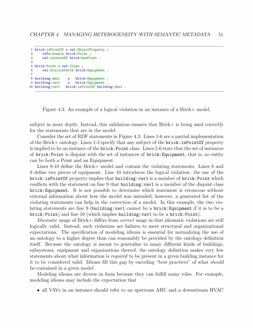
CHAPTER 4. MANAGING HETEROGENEITY WITH SEMANTIC METADATA 51
1 brick:isPointOf a owl:ObjectProperty ;2 rdfs:domain brick:Point ;3 owl:inverseOf brick:hasPoint .4
5 brick:Point a owl:Class ;6 owl:disjointWith brick:Equipment .7
8 building:ahu1 a brick:Equipment .9 building:vav1 a brick:Equipment .
10 building:vav1 brick:isPointOf building:ahu1 .
Figure 4.3: An example of a logical violation in an instance of a Brick+ model.
subject in more depth. Instead, this validation ensures that Brick+ is being used correctlyfor the statements that are in the model.
Consider the set of RDF statements in Figure 4.3. Lines 1-6 are a partial implementationof the Brick+ ontology. Lines 1-3 specify that any subject of the brick:isPointOf propertyis implied to be an instance of the brick:Point class. Lines 5-6 state that the set of instancesof brick:Point is disjoint with the set of instances of brick:Equipment; that is, no entitycan be both a Point and an Equipment.
Lines 8-10 define the Brick+ model and contain the violating statements. Lines 8 and9 define two pieces of equipment. Line 10 introduces the logical violation: the use of thebrick:isPointOf property implies that building:vav1 is a member of brick:Point whichconflicts with the statement on line 9 that building:vav1 is a member of the disjoint classbrick:Equipment. It is not possible to determine which statement is erroneous withoutexternal information about how the model was intended; however, a generated list of theviolating statements can help in the correction of a model. In this example, the two vio-lating statements are line 9 (building:vav1 cannot be a brick:Equipment if it is to be abrick:Point) and line 10 (which implies building:vav1 to be a brick:Point).
Idiomatic usage of Brick+ differs from correct usage in that idiomatic violations are stilllogically valid. Instead, such violations are failures to meet structural and organizationalexpectations. The specification of modeling idioms is essential for normalizing the use ofan ontology to a higher degree than can reasonably be provided by the ontology definitionitself. Because the ontology is meant to generalize to many different kinds of buildings,subsystems, equipment and organizations thereof, the ontology definition makes very fewstatements about what information is required to be present in a given building instance forit to be considered valid. Idioms fill this gap by encoding “best practices” of what shouldbe contained in a given model.
Modeling idioms are diverse in form because they can fulfill many roles. For example,modeling idioms may include the expectation that
• all VAVs in an instance should refer to an upstream AHU and a downstream HVAC

CHAPTER 4. MANAGING HETEROGENEITY WITH SEMANTIC METADATA 52
1 bsh:HasPointShape a sh:NodeShape ;2 sh:targetObjectsOf brick:hasPoint ;3 sh:class brick:Point ;4 sh:message "Objects of the hasPoint relationship should be Points" ;5 .6 bsh:IsPointOfShape a sh:NodeShape ;7 sh:targetSubjectsOf brick:isPointOf ;8 sh:class brick:Point ;9 sh:message "Subjects of the isPointOf relationship should be Points" ;
10 .
Figure 4.4: SHACL node shapes validating use of the Brick+ hasPoint and isPointOf
relationships
zone
• all VAVs of a particular make and model should have five associated monitoring andcontrol points
• all temperature sensors should be reporting in Celsius
Validation for Brick+ is implemented in SHACL [81] (Shapes Constraint Language), aW3C specification for describing constraints on RDF graphs. Recall that SHACL describesa graph consisting of shapes : shapes have a set of constraints and rules, which describetests for existing triples or the conditions for generation of new triples, and a target whichspecifies parts of a data graph are subject to the constraints6. SHACL defines two kindsof shapes: node shapes and property shapes. These define constraints for nodes and edges(respectively) in an RDF graph.
Correctness Validation
Brick+ shapes focus on the proper usage of relationships. Because Brick+ does notspecify any minimum level of information, the only way to incorrectly use a Brick+ class isto connect to it with an inappropriate relationship. For each of the relationships in Table 4.2,Brick+ defines a node shape which targets the subjects or objects of the relationship. Ashape targets the subjects of the relationship if there are restrictions on its domain, andtargets the objects of the relationship if there are restrictions on the range. The shape thenspecifies the intended type of the target node. Figure 4.4 contains the SHACL shape forthe hasPoint relationship. Because correct use of the hasPoint relationship only requiresthat the object is a Point, the shape itself is very simple: sh:targetObjectsOf identifiesthat the shape applies to all nodes that are objects of triples whose predicate is hasPoint;sh:class constrains the type of those nodes to be Brick’s Point class.
6§2.4 provides more background on SHACL

CHAPTER 4. MANAGING HETEROGENEITY WITH SEMANTIC METADATA 53
1 bsh:IsPartOfShape a sh:NodeShape ;2 sh:targetSubjectsOf brick:isPartOf ;3 sh:xone (4 [5 a sh:NodeShape ;6 sh:class brick:Equipment ;7 sh:property [8 sh:path brick:isPartOf ;9 sh:class brick:Equipment ;
10 ] ;11 ]12 [13 a sh:NodeShape ;14 sh:class brick:Location ;15 sh:property [16 sh:path brick:isPartOf ;17 sh:class brick:Location ;18 ] ;19 ]20 ) ;21 .
Figure 4.5: A SHACL shape enforcing the two possible uses of the isPartOf relationship.
For other relationships, the usage and implementation is more complex. The isPartOf
relationship can be used in two ways to indicate that equipment can be composed of otherequipment, or that locations can be composed of other locations. A model which indicatesthat some locations are composed of equipment (or vice versa) is incorrect. Figure 4.5implements the SHACL shape for this relationship. sh:xone specifies a list of constraints, ofwhich exactly one must be met in order for the target node to validate. The two constraintsin the list have the same structure: they each specify the expected type of the subject andobject of the relationship. The former is handled in the same way as the simpler shape inFigure 4.4, but the second constraint encoded as a property shape.
The library of correctness shapes for each of the Brick+ relationships is included in theBrick+ distribution where it can be easily accessed by tooling and applications. However, thecorrectness shapes constrain very little about the contents of a Brick+ model — for example,an empty Brick+ model is valid, but is not useful for executing any sort of data analytics.In order to specify requirements on the desired content in a Brick+ model modelers shoulduse non-normative idiomatic validation shapes.
Idiomatic Validation
Idiomatic validation is also based on SHACL node shapes, but differs from the above inits more liberal use of other SHACL features — offering more expressive requirements —and the focus on targets qualified by class rather than relationship. Shapes for idiomaticvalidation are simply all shapes that are not used for correctness. Presented here are several

CHAPTER 4. MANAGING HETEROGENEITY WITH SEMANTIC METADATA 54
1 bsh:BadVAVShape a sh:NodeShape ;2 sh:target brick:VAV3 sh:property [4 sh:path brick:hasPoint ;5 sh:class brick:Supply_Air_Temperature_Sensor ;6 sh:minCount 1;7 sh:maxCount 1;8 ], [9 sh:path brick:hasPoint ;
10 sh:class brick:Supply_Air_Temperature_Setpoint ;11 sh:minCount 1;12 sh:maxCount 1;13 ]14 .
Figure 4.6: An erroneous SHACL shape for defining two required points for VAVs
illustrative examples of common kinds of idiomatic validation shapes, and how they may beused.
Equipment Properties and Relationships: Node shapes can express what Brick+metadata must be attached to entities of a certain type. For example, in a particularbuilding it may be the case that all variable air volume box controllers have a standardset of points exposed in the BMS. By encoding these expectations in an idiomatic vali-dation shape, tooling can ensure that the Brick+ model actually describes the points andrelationships that are known to exist. Implementing these shapes requires using qualifiedSHACL constraints — simply using sh:path in property shapes to encode the expectedtype of related points results in unintuitive validation errors. Figure 4.6 contains an exam-ple of how not to do this: when two different sh:path-based property shapes are associatedwith a node shape, then fulfilling one means violating the other because the same entitywhich is the object of the relationship cannot be an instance of two (disjoint) classes. Fig-ure 4.7 shows the corrected node shape, which uses sh:qualifiedValueShape to indicatethat the property shape only applies to those entities that match the node class pointedto by sh:qualifiedValueShape. sh:qualifiedMinCount and sh:qualifiedMaxCount areanalogous to the classic sh:minCount and sh:maxCount constraints, but only apply in thesame context as the sh:qualifiedValueShape.
Site-wide Requirements: In a similar manner as the above, idiomatic validation canspecify mandatory enumerations of equipment and other expected properties of a particularsite. For example, a modeler may use metadata from external data sources to author ashape targeting an instance of a brick:Building which has exactly 10 VAVs, two AHUs,four floors, and 37 rooms. This is possible to model in SHACL using the modeling approachabove: these more complex constraint structures are necessary because Brick+ only definesa small number of relationships which may be used in different contexts.
Non-validating use of shapes: Shapes can also inform other use cases beyond val-

CHAPTER 4. MANAGING HETEROGENEITY WITH SEMANTIC METADATA 55
1 bsh:GoodVAVShape a sh:NodeShape ;2 sh:target brick:VAV3 sh:property [4 sh:path brick:hasPoint ;5 sh:qualifiedValueShape [6 sh:class brick:Supply_Air_Temperature_Sensor ;7 ] ;8 sh:qualifiedMinCount 1 ;9 sh:qualifiedMaxCount 1 ;
10 ], [11 sh:path brick:hasPoint ;12 sh:qualifiedValueShape [13 sh:class brick:Supply_Air_Temperature_Setpoint ;14 ] ;15 sh:qualifiedMinCount 1 ;16 sh:qualifiedMaxCount 1 ;17 ]18 .
Figure 4.7: The correct SHACL shape for defining two required points for VAVs.
idation. First, because shapes can be queried just like any other RDF graph, they serveas a point of reference for bootstrapping an understanding of what data may be availablein a given Brick+ model. This can be used to populate documentation pages or other vi-sualizations. Second, shapes can be used as templates for populating Brick+ models: therequired property shapes of a node shape inform the information that needs to be providedby the user, and node shape itself contains the relevant metadata necessary to automaticallyinstantiate a Brick+ entity of the right type and with the required properties.
4.4 Brick+ Formal Implementation
The features of Brick+ that make it suitable for providing consistent metadata are imple-mented in two different ontology languages: OWL-RL and SHACL. This section covers theimplementation of Brick+ and explains how it incorporates novel ontology features into atraditional ontology design. The result is a practical ontology which enables the consistentmodeling of heterogeneous systems.
Brick+ Overview
Brick+ defines a family of OWL classes and properties using the OWL ontology language.Recall that a class represents a named set; entities that are instances of a class are membersof that set. Brick+ classes categorize and define the behavior of the physical, virtual andlogical entities found in buildings. They are implemented as instances of owl:Class and areorganized into a class structure using the rdfs:subClassOf predicate. Brick+ defines three
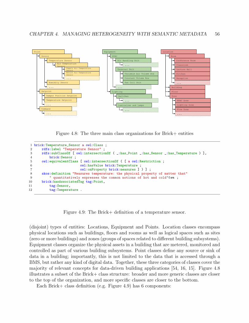
CHAPTER 4. MANAGING HETEROGENEITY WITH SEMANTIC METADATA 56
Point
Sensor
Temperature Sensor
Air Temperature Sensor
Supply Air Temperature Sensor
Humidity Sensor
Return Air Temperature Sensor
...
...
Setpoint
Damper Position Setpoint
Temperature Setpoint
...
Command
...
Equipment
HVAC
Air Handling Unit
Terminal Unit
...
Variable Air Volume Box
Constant Volume Box
Fan Coil Unit
...
Lighting
Switches
...
Luminaires and Lamps
...
Location
Room
Conference Room
Classroom
Lecture Hall
Kitchen
Reception
...
Building
Floor
Zone
HVAC Zone
Lighting Zone
Fire Zone
...
Figure 4.8: The three main class organizations for Brick+ entities
1 brick:Temperature_Sensor a owl:Class ;2 rdfs:label "Temperature Sensor" ;3 rdfs:subClassOf [ owl:intersectionOf ( _:has_Point _:has_Sensor _:has_Temperature ) ],4 brick:Sensor ;5 owl:equivalentClass [ owl:intersectionOf ( [ a owl:Restriction ;6 owl:hasValue brick:Temperature ;7 owl:onProperty brick:measures ] ) ] ;8 skos:definition "Measures temperature: the physical property of matter that"9 " quantitatively expresses the common notions of hot and cold"@en ;
10 brick:hasAssociatedTag tag:Point,11 tag:Sensor,12 tag:Temperature .
Figure 4.9: The Brick+ definition of a temperature sensor.
(disjoint) types of entities: Locations, Equipment and Points. Location classes encompassphysical locations such as buildings, floors and rooms as well as logical spaces such as sites(zero or more buildings) and zones (groups of spaces related to different building subsystems).Equipment classes organize the physical assets in a building that are metered, monitored andcontrolled as part of various building subsystems. Point classes define any source or sink ofdata in a building; importantly, this is not limited to the data that is accessed through aBMS, but rather any kind of digital data. Together, these three categories of classes cover themajority of relevant concepts for data-driven building applications [54, 16, 15]. Figure 4.8illustrates a subset of the Brick+ class structure: broader and more generic classes are closerto the top of the organization, and more specific classes are closer to the bottom.
Each Brick+ class definition (e.g. Figure 4.9) has 6 components:

CHAPTER 4. MANAGING HETEROGENEITY WITH SEMANTIC METADATA 57
Relationship Definition Domain Range Inverse Transitive?
hasLocation Subject is physically located in the object * Location isLocationOf yes
feedsSubject conveys some media to theobject in some sequential process
Equipment EquipmentisFedBy no
Equipment Location
hasPoint Subject has a monitoring, sensing or controlpoint given by the object
* Point isPointOf no
hasPartSubject is composed – logically orphysically – in part by the object
Equipment EquipmentisPartOf yes
Location Location
Table 4.2: Brick+ relationships for associating entities with each other
• A unique URI in the Brick+ name space (line 1 of Figure 4.9)
• A human-readable label identified by rdfs:label (line 2 of Figure 4.9)
• A human-readable definition identified by skos:definition (lines 8-9 of Figure 4.9)
• One or more parent classes identified by rdfs:subClassOf (line 3-4 of Figure 4.9)
• Any associated tags, identified by brick:hasAssociatedTag (line 10-12 of Figure 4.9)
• Semantic properties which define the class. These use a variety of property names, asexplored in the next section (line 5-7 of Figure 4.9)
Several of these are simply annotations on the class definition. rdfs:label, skos:definitionand brick:hasAssociatedTag can be queried by tooling and applications, but do not affector contribute to the formal implementation of Brick. The other properties, discussed below,are interpreted by a reasoner to insert inferred information into the graph.
Brick+ relationships connect entities together to form the model representing a partic-ular building. Brick+ defines a small, orthogonal set of relationships — implemented asOWL object properties — which capture composition, topology, telemetry and other asso-ciations between entities that are required for authoring data-driven applications. Theserelationships, carried over from the original Brick+ release, are listed in Table 4.2.
However, the class organization and relationship definitions alone are not enough to guar-antee the consistent extensibility of the Brick+ ontology. To address these issues, Brick+includes formal definitions of semantic properties and tags; these enable the structured ex-tension of Brick+ and allow new and richer kinds of metadata to be associated with Brick+entities.
Brick+ Tag Implementation
In Brick, tags are entities which are instances of the brick:Tag class. Brick+ tags have noassociated definition, and thus are not designed to provide any additional semantic context toclasses or entities. Tags are associated with Brick+ classes via the brick:hasAssociatedTag

CHAPTER 4. MANAGING HETEROGENEITY WITH SEMANTIC METADATA 58
1 brick:Temperature_Sensor a owl:Class ;2 rdfs:subClassOf [ # beginning of the OWL intersection class definition3 owl:intersectionOf ( # the list of tag classes4 [ a owl:Restriction ; # restriction class for "Temperature" tag5 owl:hasValue tag:Temperature ;6 owl:onProperty brick:hasTag ]7 [ a owl:Restriction ; # restriction class for "Sensor" tag8 owl:hasValue tag:Sensor ;9 owl:onProperty brick:hasTag ]
10 [ a owl:Restriction ; # restriction class for "Point" tag11 owl:hasValue tag:Point ;12 owl:onProperty brick:hasTag ]13 )14 ], brick:Sensor .
Figure 4.10: Part of the brick:Temperature Sensor class definition from Figure 4.9, show-ing the unoptimized full implementation of the OWL intersection class
relationship, and are associated with Brick+ entities via the brick:hasTag relationship.These two relationships differentiate if a tag is intended as part of a definition (for classes)or to facilitate discovery (for entities). Having two different relationships also makes itpossible for a reasoner to differentiate between the two use cases of tags.
Brick+ uses a reasoner to automatically add the appropriate tags to all instances of aBrick+ class (referred to as class→tag inference). To implement this, each Brick+ classdefinition has a rdfs:subClassOf relationship to a unique OWL intersection class whichencodes the required tags for that class. An OWL intersection class is defined by the con-junction of membership in other classes: if an entity is a member of each of the indicatedclasses, it is inferred to be a member of the intersection class. In the Brick+ tag implementa-tion, the constituent classes to the OWL intersection class are OWL restriction classes whichindividually encode the tag that is to be inherited. OWL restriction classes are defined by aset of conditions; an entity is inferred to be an instance of a restriction class if it meets allof the conditions.
Three restriction class definitions can be seen in Figure 4.10 on lines 4-6, 7-9 and 10-12. Each of the classes is characterized by a single condition which is that the entity has agiven tag as the value of brick:hasTag. By making a Brick+ class a subclass of the OWLintersection class, any instance of the Brick+ class is also inferred to be a member of theintersection class, and thus also a member of each of the constituent classes. The inheritanceof the OWL restriction classes enables the reasoner to attach the appropriate tags to theBrick+ entity.
One optimization that Brick+ includes in the implementation is the re-use of tag restric-tion classes. In many ontologies, the OWL restriction classes and OWL intersection classesare anonymous classes called blank nodes; these are typically used and defined in the sameplace in the file (such as in Figure 4.10). This results in a large number of duplicate restriction
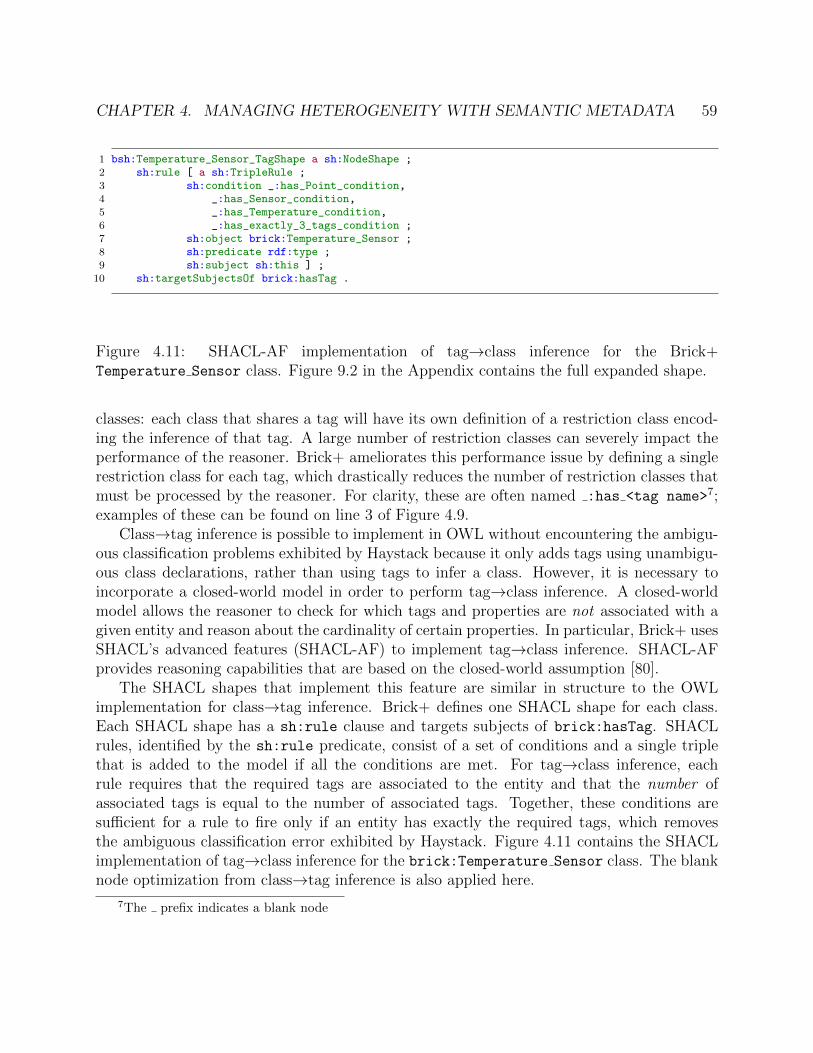
CHAPTER 4. MANAGING HETEROGENEITY WITH SEMANTIC METADATA 59
1 bsh:Temperature_Sensor_TagShape a sh:NodeShape ;2 sh:rule [ a sh:TripleRule ;3 sh:condition _:has_Point_condition,4 _:has_Sensor_condition,5 _:has_Temperature_condition,6 _:has_exactly_3_tags_condition ;7 sh:object brick:Temperature_Sensor ;8 sh:predicate rdf:type ;9 sh:subject sh:this ] ;
10 sh:targetSubjectsOf brick:hasTag .
Figure 4.11: SHACL-AF implementation of tag→class inference for the Brick+Temperature Sensor class. Figure 9.2 in the Appendix contains the full expanded shape.
classes: each class that shares a tag will have its own definition of a restriction class encod-ing the inference of that tag. A large number of restriction classes can severely impact theperformance of the reasoner. Brick+ ameliorates this performance issue by defining a singlerestriction class for each tag, which drastically reduces the number of restriction classes thatmust be processed by the reasoner. For clarity, these are often named :has <tag name>7;examples of these can be found on line 3 of Figure 4.9.
Class→tag inference is possible to implement in OWL without encountering the ambigu-ous classification problems exhibited by Haystack because it only adds tags using unambigu-ous class declarations, rather than using tags to infer a class. However, it is necessary toincorporate a closed-world model in order to perform tag→class inference. A closed-worldmodel allows the reasoner to check for which tags and properties are not associated with agiven entity and reason about the cardinality of certain properties. In particular, Brick+ usesSHACL’s advanced features (SHACL-AF) to implement tag→class inference. SHACL-AFprovides reasoning capabilities that are based on the closed-world assumption [80].
The SHACL shapes that implement this feature are similar in structure to the OWLimplementation for class→tag inference. Brick+ defines one SHACL shape for each class.Each SHACL shape has a sh:rule clause and targets subjects of brick:hasTag. SHACLrules, identified by the sh:rule predicate, consist of a set of conditions and a single triplethat is added to the model if all the conditions are met. For tag→class inference, eachrule requires that the required tags are associated to the entity and that the number ofassociated tags is equal to the number of associated tags. Together, these conditions aresufficient for a rule to fire only if an entity has exactly the required tags, which removesthe ambiguous classification error exhibited by Haystack. Figure 4.11 contains the SHACLimplementation of tag→class inference for the brick:Temperature Sensor class. The blanknode optimization from class→tag inference is also applied here.
7The prefix indicates a blank node

CHAPTER 4. MANAGING HETEROGENEITY WITH SEMANTIC METADATA 60
Substances and Quantities
To support richer semantic definitions of classes, Brick+ defines a set of substances andquantities which can be used to capture the behavior and purpose of a point or equipment.A substance is any physical medium that can be observed or manipulated, including air,water, light, electricity and gas. Brick+ defines several more specific kinds of substancesto clarify the phase of matter or the purpose within a larger subsystem. For example, thedefinition of water has several more specific flavors including ice and water vapor (phasesof matter), but also potable water, supply water, return water and other subsystem-specificuses of water.
In Brick, substances are instances of the brick:Substance class rather than being classesthemselves. This simplifies their usage by removing the need to create an instance of asubstance that can be related to a Brick+ class or entity. Even though substances areinstances rather than classes, it is still helpful to organize them. Brick+ uses the SimpleKnowledge Organization System’s skos:broader and skos:narrower properties to relatesubstances as being more general or more specific than each other. These properties arenot interpreted by a reasoner; they only provide organization to the substances to facilitatediscovery.
A quantity represents a quantifiable property of a substance. The set of quantities de-fined in Brick+ is based on QUDT’s QuantityKind class [75], and includes quantities such asthermodynamic temperature, active power, volume and volumetric flow. By linking Brick’squantities to those defined by QUDT, Brick+ can also embed suggestions for units of mea-sure that may be associated with points. For example, any Brick+ point that is associatedwith the brick:Temperature quantity (representing thermodynamic temperature) can beautomatically inferred to support units of Celsius, Fahrenheit or Kelvin. Like substances,quantities are instances of a root class (brick:Quantity) rather than being classes them-selves.
Even though substances and quantities may share the same names as tags (e.g. brick:Air,the substance, and tag:Air the tag), they are placed into different namespaces in order todifferentiate which terms have significant semantic meaning and which are simply annota-tions.
Semantic Properties
Brick+ defines a family of semantic properties that augment the rdfs:subClassOf rela-tionship with additional metadata about the behavior and purpose of entities. Recall thatsemantic properties are a tuple (pi, vi) where pi is a property name and vi is the propertyvalue. Many semantic properties have a value that is drawn from the dictionary of substancesand quantities defined by Brick. The property name qualifies the nature of the relationshipbetween the class definition and the substance or quantity. Table 4.3 defines a few of theproperty names defined in Brick+ as well as their ranges (the type of the property value)and domains (the type of the entity that has the semantic property).

CHAPTER 4. MANAGING HETEROGENEITY WITH SEMANTIC METADATA 61
Property Name Definition Domain Range
measuresIdentifies the quantity or substance thatis measured by a point
brick:Sensorbrick:Substance
brick:Quantity
regulatesIdentifies the quantity or substance thatis regulated by an equipment
brick:Equipmentbrick:Substance
brick:Quantity
hasInputSubstanceIdentifies a substance that flows into anequipment
brick:Equipment brick:Substance
hasOutputSubstanceIdentifies a substance that flows out of anequipment
brick:Equipment brick:Substance
Table 4.3: A set of semantic property name definitions
Each Brick+ class is bound to a unique set of semantic properties. This is implementedas an OWL intersection class which models the conjunction of an entity having each of therequired semantic properties; each of the constituent classes is an OWL restriction class.Due to this construction, each Brick+ class has a superset of the semantic properties ofits parent. The semantic properties are assigned such that classes with n + 1 semanticproperties are subclasses of classes with an n-sized subset of those semantic properties. Therdfs:subClassOf relationships between classes make this relationship explicit. Figure 4.12depicts the resulting lattice for a subset of the brick:Point class organization.
Consider the example of the brick:Temperature Sensor class depicted in Figure 4.9.This class is characterized by one semantic property: a brick:Temperature Sensor mea-sures the temperature quantity of some yet-unspecified substance. Lines 5-7 of Figure 4.9contain the definition of this single OWL restriction class and the encapsulating OWL in-tersection class.
Importantly, and unlike tags, semantic properties are interchangeable with the class defi-nition. For this reason, the implementation relates the OWL intersection class to the Brick+class using the owl:equivalentClass predicate. This informs an OWL reasoner that it caninfer the semantic properties for an entity from the class definition as well as infer the classfrom a set of semantic properties. The semantic properties for a class are inherited all en-tities which are instances of that class. This allows semantic properties to be used not justfor structuring the extensibility of Brick’s class organization, but also for discovering entitiesusing richer annotations than simple tags.
Entity Properties
Classes provide helpful organization for groups of entities, but there are many potential usesof a Brick+ model which require additional information about individual entities. To modelthis metadata, Brick+ introduced a new entity properties component to the ontology. Entityproperties are similar to semantic properties in that they are a tuple (pi, vi) where pi is theproperty name and vi is the property value, but differ in two important ways:
1. The values of entity properties are structured objects, rather than single values
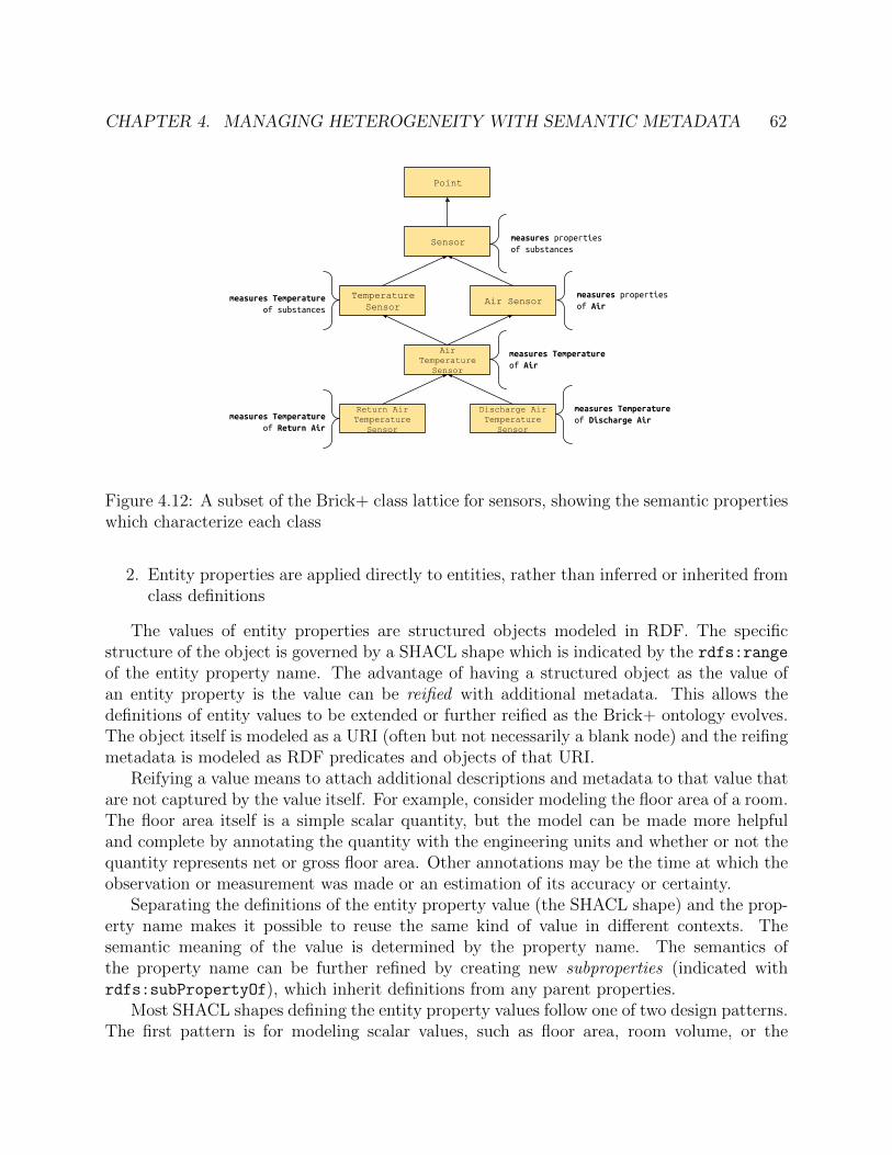
CHAPTER 4. MANAGING HETEROGENEITY WITH SEMANTIC METADATA 62
Point
Sensor
Temperature Sensor
Air Temperature
Sensor
Air Sensormeasures Temperature of substances
measures properties of Air
measures Temperature of Air
measures properties of substances
Return Air Temperature
Sensor
Discharge Air Temperature
Sensor
measures Temperature of Discharge Airmeasures Temperature
of Return Air
Figure 4.12: A subset of the Brick+ class lattice for sensors, showing the semantic propertieswhich characterize each class
2. Entity properties are applied directly to entities, rather than inferred or inherited fromclass definitions
The values of entity properties are structured objects modeled in RDF. The specificstructure of the object is governed by a SHACL shape which is indicated by the rdfs:range
of the entity property name. The advantage of having a structured object as the value ofan entity property is the value can be reified with additional metadata. This allows thedefinitions of entity values to be extended or further reified as the Brick+ ontology evolves.The object itself is modeled as a URI (often but not necessarily a blank node) and the reifingmetadata is modeled as RDF predicates and objects of that URI.
Reifying a value means to attach additional descriptions and metadata to that value thatare not captured by the value itself. For example, consider modeling the floor area of a room.The floor area itself is a simple scalar quantity, but the model can be made more helpfuland complete by annotating the quantity with the engineering units and whether or not thequantity represents net or gross floor area. Other annotations may be the time at which theobservation or measurement was made or an estimation of its accuracy or certainty.
Separating the definitions of the entity property value (the SHACL shape) and the prop-erty name makes it possible to reuse the same kind of value in different contexts. Thesemantic meaning of the value is determined by the property name. The semantics ofthe property name can be further refined by creating new subproperties (indicated withrdfs:subPropertyOf), which inherit definitions from any parent properties.
Most SHACL shapes defining the entity property values follow one of two design patterns.The first pattern is for modeling scalar values, such as floor area, room volume, or the
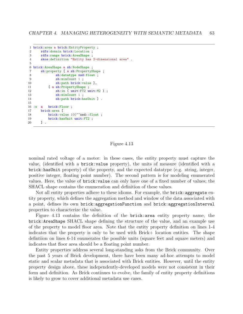
CHAPTER 4. MANAGING HETEROGENEITY WITH SEMANTIC METADATA 63
1 brick:area a brick:EntityProperty ;2 rdfs:domain brick:Location ;3 rdfs:range brick:AreaShape ;4 skos:definition "Entity has 2-dimensional area" .5
6 brick:AreaShape a sh:NodeShape ;7 sh:property [ a sh:PropertyShape ;8 sh:datatype xsd:float ;9 sh:minCount 1 ;
10 sh:path brick:value ],11 [ a sh:PropertyShape ;12 sh:in ( unit:FT2 unit:M2 ) ;13 sh:minCount 1 ;14 sh:path brick:hasUnit ] .1516 :x a brick:Floor ;17 brick:area [18 brick:value 100^^xsd::float ;19 brick:hasUnit unit:FT2 ;20 ] .
Figure 4.13
nominal rated voltage of a motor: in these cases, the entity property must capture thevalue, (identified with a brick:value property), the units of measure (identified with abrick:hasUnit property) of the property, and the expected datatype (e.g. string, integer,positive integer, floating point number). The second pattern is for modeling enumeratedvalues. Here, the value of brick:value can only have one of a fixed number of values; theSHACL shape contains the enumeration and definition of these values.
Not all entity properties adhere to these idioms. For example, the brick:aggregate en-tity property, which defines the aggregation method and window of the data associated witha point, defines its own brick:aggregationFunction and brick:aggregationInterval
properties to characterize the value.Figure 4.13 contains the definition of the brick:area entity property name, the
brick:AreaShape SHACL shape defining the structure of the value, and an example useof the property to model floor area. Note that the entity property definition on lines 1-4indicates that the property is only to be used with Brick+ location entities. The shapedefintiion on lines 6-14 enumerates the possible units (square feet and square meters) andindicates that floor area should be a floating point number.
Entity properties address several long-standing asks from the Brick community. Overthe past 5 years of Brick development, there have been many ad-hoc attempts to modelstatic and scalar metadata that is associated with Brick entities. However, until the entityproperty design above, these independently-developed models were not consistent in theirform and definition. As Brick continues to evolve, the family of entity property definitionsis likely to grow to cover additional metadata use cases.

CHAPTER 4. MANAGING HETEROGENEITY WITH SEMANTIC METADATA 64
Conclusion
In order to provide a consistent metadata model that can describe the heterogeneous settingstypical of cyberphysical systems, it is not enough to simply define a dictionary of tagsor terms which can annotate data streams. Brick adopts a formal, graph-based modelwhich not only provides a rich and extensible dictionary of concepts, but provides a meansfor instances of concepts to be related to one another. This chapter demonstrated newontology design techniques which provide facilities for structured extension of the ontology,ensuring that additions can be done in a consistent and interpretable manner. Brick alsoprovides an alternative and usable implementation of tagging for both entities and concepts,and incorporates a new entity properties feature which associates reiified metadata withinstances of Brick classes. Together, these features enable the robust modeling of complexcyberphysical systems, and provide a framework for implementing self-adapting software.

65
Chapter 5
Expressing Self-Adapting Software
Write once, run everywhere.
Sun Microsystems
Self-adapting software leverages structured and semantically-rich descriptions of its de-ployment in order to automatically configure its operation to that environment. The priorchapter demonstrated how graph-based metadata models, such as Brick, can capture thenecessary information to enable self-adapting software; however, the challenge remains howto actually write self-adapting software. How does software express what the requirementsare for its operation, and how its structure and execution should react to different configu-rations of its environment? What are the supporting systems, databases and programmingruntimes that enable the efficient execution self-adapting software? How can the potentialcomplexity of self-adapting software be automated or otherwise abstracted away from theprogrammer?
Two models for expressing and executing self-adapting software are examined. First, thechapter details a staged execution model for self-adapting software. Software describes thedata and metadata requirements for its operation in an application manifest. To determine ifand how software can execute in a given deployment, the software’s manifest is evaluated onthe metadata model for that deployment. The results of this evaluation provide the applica-tion with the information it needs to determine if it can execute and, if it can execute, how toconfigure itself and adapt its logic to the deployment. While straightforward to implement,the programming model outsources much of the complexity of self-adaptation logic to theuser. The chapter then contrasts the staged programming model with an interactive ap-proach that abstracts away much of the bookkeeping associated with writing self-adaptationlogic.
Definition 5.0.1 (Environment). An environment is the cyberphysical context in which apiece of software is running. This includes, but is not limited to, the networked resourcesavailable to the software, the structure and topology of the cyberphysical subsystems affecting

CHAPTER 5. EXPRESSING SELF-ADAPTING SOFTWARE 66
Figure 5.1: Logical workflow for application configuration and execution
the environment (such as HVAC, lighting and electrical subsystems in buildings), and anyhistorical telemetry about the environment.
5.1 Using Metadata for Configuration
The kinds of rich semantic metadata detailed in §4 can inform the execution of self-adaptingsoftware in several ways. An effective programming model for self-adapting software must:
• allow software to access the metadata representation of an environment to determineif the environment is appropriate and if there is sufficient metadata for the applicationto operate
• allow software to adapt its execution with respect to the available metadata about anenvironment
Metadata-Driven Software Portability
Definition 5.1.1 (Portability). Portability is the quality of a piece of software that describesthe extent to which the software can adapt the execution of its functionality to a given envi-ronment without human interaction or configuration. Generally speaking, the more portablea piece of software is, the more environments it may execute in. Non-portable software mayonly run on 1 or a small number of environments; this is characteristic of most data-orientedcyberphysical software deployed today.
Self-adapting software queries the metadata model of an environment in order to un-derstand how the software should adapt its behavior. The first task that these queries

CHAPTER 5. EXPRESSING SELF-ADAPTING SOFTWARE 67
accomplish is establishing whether or not the environment is appropriate for the software.This predicate, which is specific to the logic of the application, is evaluated by querying theenvironment for the kind and structure of the subsystems that are required by the software
Cyberphysical systems are heterogeneous and are characterized by unique, one-off de-signs. However, while the exact instantiations of these subsystems differ significantly frombuilding to building, most subsystems of a particular type will contain similar kinds ofequipment organized into similar topologies. For example, recall from Chapter 2 that con-ditioning the air in buildings may be performed through air-based HVAC systems (usuallywith a complex AHU-based system in larger buildings, and simpler RTU-based systems insmaller buildings), or through water-based radiant systems. In each of these systems, a sub-stance (water or air) can be traced through different equipment which regulate or conditiondifferent properties of that substance until the substance reaches a point where it interactswith the human-occupied parts of the environment. The functional relationships betweenthese components can be captured in a general manner (Chapter 4).
Self-adapting software will query the environment to identify which kinds of subsystemsare installed, and use the results to determine how to adjust the operation. Query results candrive an algorithmic change — such as what kind of model is trained or which fault conditionsare tested — but may also lead the application to terminate early due to a lack of availablemetadata or the presence of a subsystem which is incompatible with the application’s intent.
Once the software knows the structure of the environment it is interacting with, it canthen query the metadata model for application- and subsystem-specific configuration. Fordata-driven applications, this includes retrieving the names, units and other salient metadatafor any points and other data streams required for operation. This is complemented withcontextual information about the data streams, such as which equipment or location theyare associated with.
Figure 5.1 illustrates a logical execution model for self-adapting applications in a Brickcontext. The queries describing the application’s semantic and data requirements are eval-uated on a Brick model database, which stores the metadata representation of the currentenvironment. The answers to these queries give the application the foreign keys or otheridentifiers necessary to retrieve historical and live telemetry for any relevant data sources.This bootstrapping process can then forward the resulting metadata and data to the rest ofthe application.
There are fundamental limits to the portability of an application. The most portablesoftware is an application that requires no metadata about its environment. However, mostuseful applications require certain assumptions to hold for the application’s logic to be ap-propriate. For example, an application that is detecting broken fans in a building will likelyneed to know what kinds of data are available for the fans in the building. If a building hasno fans, then the application is not appropriate for the building. Further, an application’sability to operate in a certain environment also depends on the metadata available aboutthe environment. An incomplete or out of date metadata model of an environment will alsoimpact how well, or if, software can run in that environment. Techniques and systems formaintaining and managing metadata models over time are described in Chapter 6.

CHAPTER 5. EXPRESSING SELF-ADAPTING SOFTWARE 68
Another crucial component to application portability is the existence of common APIs foraccessing the metadata model and telemetry for a building. Past work such as sMAP [40] andrecent commercial platforms address how to extract data from cyberphysical environments.Chapter 7 discusses APIs and platforms that support self-adapting software.
SPARQL Queries for Application Configuration
The SPARQL query language is a W3C standard for querying and manipulating RDF graphs,and is an essential tool for accessing the contents of metadata models. Self-adapting soft-ware leverages SPARQL features and ontology structure (using the features described inChapter 4) to account for the both the heterogeneity of cyberphysical systems in the envi-ronment and the heterogeneity in the graph structure describing that environment. Thisallows effectively-written software to remain somewhat agnostic to the content and structureof the metadata model, which increases portability. SPARQL has a large number of features,but only a subset of them are necessary to support self-adapting software. The overview ofSPARQL presented here will focus on the major features of SPARQL 1.1 [66] used in thiscontext.
A SPARQL query has two primary components: the SELECT clause which indicates whichvariable bindings to return from the query execution, and the WHERE clause which specifiesthe predicates on and relationships between variables. A variable is identified with a ? prefix,e.g. ?x and ?ahu. The name of a variable has no semantic significance, though for clarityvariables often retain names similar to what they will be bound to.
The WHERE clause consists of a set of graph patterns, which are made up of triple patternsand other operators. A triple pattern has a similar structure to an RDF triple. It is composedof:
• a subject : a variable or URI
• a predicate: a variable, URI or property path [66]
• a object : a variable, URI or literal
Triple patterns describe the parts of a graph that must be matched for the query predicateto be true. The flexibility of this matching is what allows SPARQL queries to executesuccessfully over heterogeneous graphs. Property paths are a key feature of SPARQL whichfacilitate this flexibility. A property path is a complex pattern of RDF predicates and queryvariables which can match transitive closures (0 or more of the same predicate in sequence),optional predicates, alternative predicates, explicit sequences of predicates, and negations ofthe above. Triple patterns are joined together into a graph pattern by the “.” conjunctionoperator. Many WHERE clauses consist of a single graph pattern; however, it is also possibleto union multiple graph patterns (where “.” is a logical “and”, the union is a logical “or”)to express more complex query predicates. The programming models explored below differprimarily in how and when SPARQL queries are expressed and executed.

CHAPTER 5. EXPRESSING SELF-ADAPTING SOFTWARE 69
AHU Class
VAV Class
Damper Class
HVAC Zone Class Room
feeds feeds feeds hasPart
hasPart
type type type type type type
AHU Class
VAV Class
Damper Class
HVAC Zone Class Room
feeds
hasPart
feeds hasPart
hasPart
type type type type type
type
AHU Class
HVAC Zone Class Room
feeds hasPart
hasPart
type type type type
hasPart
(a)
(b) (c)
Figure 5.2: Three different Brick models describing the same physical system. It is possibleto author a single SPARQL query which will retrieve the names of the AHU and downstreamrooms, independent of the specific structure of the graph.
Handling Heterogeneous Graph Structures
To be portable, self-adapting software must be able to find the metadata it requires in manydifferent graphs. Even for the same cyberphysical system, differences in the metadata modelgraph may arise for several reasons. Primary among these is the availability of informa-tion: not all cyberphysical systems have a complete description available that can informthe creation of the metadata model. Another reason graph structures may differ is the effortrequired to make more complete models, or differences in opinion for how the model shouldbe constructed. The combination of property paths and the small and expressive set of pred-icates supported by a cyberphysical ontology like Brick allow SPARQL queries to generalizeto many different graph structures. Brick’s design goals of consistency and interpretabilityfacilitate this task in three concrete ways.
First, the small number of predicates defined by the ontology mean there is a limited num-ber of ways in which components can be related to one another. Because Brick’s predicateshave orthogonal semantics, it is usually obvious which predicate should or would be used torelate a given pair of entities. For example, entities representing a sequence of equipment ina subsystem will be related to one another using the brick:feeds relationship.
Second, the class organization makes it easier for modelers to choose consistenttypes for the entities they are modeling. Brick currently defines over 700 differentclasses, each with a human-readable definition which can clarify the meaning of theclass. The hierarchical nature of the class organization also makes it possible to dis-cover entities based on more generic types. This removes the need to know the ex-act type associated with an entity in order to find it with a SPARQL query. For ex-ample, an entity with a type of brick:Discharge Air Temperature Sensor is also an

CHAPTER 5. EXPRESSING SELF-ADAPTING SOFTWARE 70
1 SELECT ?ahu ?room WHERE {2 ?ahu a brick:AHU .3 ?ahu brick:feeds+ ?zone .4 ?zone brick:hasPart ?room5 }
Figure 5.3: A SPARQL query which finds the AHU and two rooms in each of the graphs inFigure 5.2.
instance of brick:Air Temperature Sensor, brick:Temperature Sensor, brick:Sensor
and brick:Point.Third, the semantic properties that contextualize class definitions can also be used to
discover relevant entities in terms of their behavior and purpose, rather than the name oftheir type. For example, it may be more natural for a query author to ask the metadatamodel for “all sensors which measure air temperature and are downstream of a particularVAV” rather than “all discharge air temperature sensors downstream of a particular VAV”.
These design properties of cyberphysical ontologies such as Brick ensure consistency andcompatibility in modeling choices, and provide multiple ways of finding the same information.Property paths in SPARQL queries help address other variances in how the metadata modelis expressed. This is best illustrated with an example. Figure 5.2 depicts three different Brickmodels describing the same basic HVAC system consisting of an AHU, VAV containing adamper and an HVAC zone containing two rooms. Model (a) depicts a damper as explicitlyin the flow of air from the VAV to the zone. Model (b) models the damper as part of theVAV, but does not place it in the air flow sequence. Model (c) omits the VAV and damperentirely.
The query in Figure 5.3 successfully finds the AHU and room entities in each of the graphsin Figure 5.2. The query uses the brick:feeds relationship to match an “upstream/down-stream” relationship between the AHU and the rooms to which it supplies air. To account fordifferent levels of detail with relation to the equipment that are modeled in that air supply,the query uses a transitive closure on the brick:feeds relationship to match any arbitrarysequence of those edges (line 3).
5.2 Programming Models for Self-Adapting Software
This section describes and reviews two proposed programming models for self-adapting soft-ware, termed staged and interactive. The two approaches both use SPARQL queries to ac-cess the metadata model describing a particular environment, but differ in how the SPARQLqueries are expressed, when they are executed, and how the results are incorporated into theexecution and adaptation of software. The programming models are discussed in the context

CHAPTER 5. EXPRESSING SELF-ADAPTING SOFTWARE 71
fetch clean analyze
aggregatefetch clean analyze
fetch clean analyze
…
…
… qualify
Execute for each building returned from qualify
Figure 5.4: Architecture of an application written in the staged programming model
of analytics for buildings, driven by metadata expressed using the Brick ontology; however,the techniques and methods do generalize to other cyberphysical settings and ontologies.
Staged Programming Model for Large-Scale Analysis
Many implementations of cyberphysical analytics are not portable due to hard-coded pointnames — a characteristic that is addressed with expressive metadata models — but alsotightly-coupled phases of operation which make assumptions about the nature and availabil-ity of data. The staged programming model is so-named because it decomposes the structureof a self-adapting application into discrete phases of operation which can individually enforcekey assumptions for other parts of the application. Earlier phases can handle unit conversion,perform data cleaning, patch missing data and ensure that required data exists. Decouplingdata preparation from the analysis simplifies the implementation of the latter. The modularapplication structure also has the benefit of providing re-usable and re-mixable componentswhich can reduce development effort and assist in reproducibility.
The staged programming model decomposes analytics applications into five phases:qualify, fetch, clean, analyze and aggregate. These stages are executed by an ap-plication runtime, a library abstracting away access to the metadata and data stores. Thestructure of the backing analytics platform is described in Chapter 7. Figure 5.4 depicts theflow of execution of a generic self-adapting application expressed in the staged programmingmodel.
The explanations of each of the stages below will follow a running example of a “roguezone detection application”. This application examines pairs of air flow sensors and set-points for each HVAC zone in a building and identifies zones where the measured air flow issignificantly above or below the setpoint for an extended range of time.
Qualify Stage
The qualify component of a self-adapting application defines the metadata and data require-ments of an application in a declarative manner. The evaluation of the qualify component

CHAPTER 5. EXPRESSING SELF-ADAPTING SOFTWARE 72
1 # identifies pairs of sensor/setpoint to be compared2 SELECT ?sensor ?setpoint ?equip WHERE {3 ?setpoint a brick:Air_Flow_Setpoint .4 ?sensor a brick:Air_Flow_Sensor .5 ?sensor brick:isPointOf ?equip .6 ?setpoint brick:isPointOf ?equip7 }8
9 # (optional) identifies which zones might be effected10 SELECT ?equip ?zone ?room WHERE {11 ?equip a brick:Terminal_Unit .12 ?zone a brick:HVAC_Zone .13 ?equip brick:feeds+ ?zone .14 ?zone brick:hasPart ?room15 }
Figure 5.5: Two SPARQL queries used in the qualify step of a rogue zone detection appli-cation.
gates the further execution of the application; if the specified conditions are not met, thenthe application terminates its execution. One valuable property of the qualify componentis it can be used to filter down a large set of environments to just the set on which anapplication can execute; this is instrumental to the implementation of the Mortar buildinganalytics platform described in Chapter 7. The set of environments that fulfill the qualify
stage’s predicates are the execution set of the application.The qualify stage of an application consists of a set of SPARQL queries which are eval-
uated against a collection of environments. The output of this stage is a table of how manyresults each query returned for each environment. The application uses this information tomake a decision about whether or not to qualify each environment. A simple predicate wouldbe to qualify an environment only if all queries returned at least 1 result. More complexpredicates could inform the creation of a decision tree which uses the successful executionof some queries to inform the choice of which other queries should return results in order toqualify the environment.
Figure 5.5 contains two SPARQL queries which would be used in the qualify step ofthe running example of a rogue zone detection application. The first query guarantees theexistence of the sensor and setpoint data streams which are required by the application.The ?equip variable allows the correct data streams to be compared with one another. Thesecond query, which could have been incorporated into the first, is listed separately becauseit is optional. The results of the second query provide valuable context for which zones androoms would be affected by the fault condition and thus considered one of the “rogue zones”.However, this useful context is not strictly necessary for the application to run, so makingthis metadata a supplementary part of the application ensures that the application is morepermissive in the set of environments it can execute on.

CHAPTER 5. EXPRESSING SELF-ADAPTING SOFTWARE 73
pymortar.DataFrame definition
client.fetch()
pandas.DataFrame results
Figure 5.6: Dataframe definition in Python (left) and the resulting dataframes (right)
Fetch Stage
The fetch component of a self-adapting application describes and retrieves the data requiredfor the application to run. The component is expressed as a declarative specification of adataset. Specifically, this consists of:
• Views: A view contains metadata requested by the application. It is defined as anamed SPARQL query, the evaluation of which on a given environment produces atable of the results. A fetch component can contain many view definitions.
• Dataframes: a dataframe is a time-indexed table of data requested by the application.The data stream included in a dataframe are determined by the variable bindings fromone or more views ; the author of the dataframe definition chooses which variablescorrespond to interesting data. The dataframe definition also specifies how the datafor each variable is to be aggregated, including the method and window of aggregation.A fetch component can contain many dataframe definitions.
• Time range: this defines the temporal range of data to be retrieved. A fetch com-ponent contains exactly one time range.
An application contains a single fetch component that is executed on each of the envi-ronments in the execution set. Executing the fetch component means evaluating the viewand dataframe definitions on the metadata model and associated databases for each environ-ment. The output of this evaluation is an object providing access to the now-populated viewsand dataframes described by the application. The representation of views and dataframesdepends on the host language of the programming environment. In the Mortar platform [52,

CHAPTER 5. EXPRESSING SELF-ADAPTING SOFTWARE 74
siteCompSciHall
CompSciHall
CompSciHall
CompSciHall
...
AutogeneratedFrom SELECT clause
pymortar.View definition
s
sen1
sen2
sen3
sen4
...
sp
sp1
sp2
sp3
sp4
...
equip
vav1
vav2
fcu1
fcu2
...
s_uuid...-9788bdf63cf0
...-d7c96010da5c
...-b1607a419aa4
...-89f84f4ec34e
...
sp_uuid...-22d998555a35
...-48b700ed841b
...-1140b5c47b67
...-1e3937209cee
...
s_unit
CFM
CFM
CFM
CFM
...
sp_unit
CFM
CFM
CFM
CFM
...
client.fetch()
Figure 5.7: View definition in Python (left) and resulting table (right)
53], views are represented as in-memory SQL tables; this facilitates additional grouping,filtering and other operations on the metadata. Dataframes are represented as in-memoryPandas dataframes, which facilitates manipulation, filtering and computation.
Figure 5.7 contains the definition of a view for the rogue zone detection application. Thetable containing the results of the evaluated view receives several auto-generated columnswhich contain metadata about the data associated with the point entities that are returnedin the query. Each row of the table corresponds to one set of bindings to the variables in theSELECT clause.
Figure 5.6 contains the definition of two dataframes for the rogue zone detection applica-tion: one containing the data for the air flow sensors (aggregated using a 15-minute mean)and another containing the data for the air flow setpoints (aggregated using a 15-minutemax). Data semantics inform the choice to use two dataframes: retrieving the min or maxsetpoint in a given window ensures that the data reflects real setpoint values; however for thesensor it is more important to use an aggregation that captures characteristic rather than ex-treme readings. Evaluating the two dataframe definitions produces two objects that containthe timeseries for each of the entities bound to the respective variables for that dataframe;for example, the id column of the “air flow sensor” dataframe will contain identifiers foreach of the air flow sensors found in the view.
Clean Stage
The clean component of a self-adapting application executes on the output of the fetch
component. This component of the application fulfills a vital role in ensuring applicationportability that is not addressed by the ontology structure and flexible SPARQL queries: datanormalization. This includes, but is not limited to, aligning data to a common timeframe(such as on the hour) and filling in data holes by extrapolating historical data. One commonoperation is dropping ranges of data which contain invalid or missing values so that each setof data streams that will be computed on together has a shared set of timestamps. By makingthis data cleaning and normalization step a distinct stage of execution, it is possible for otherapplication authors to borrow or repurpose data cleaning code from existing applications.This provides an explicit mechanism for reusing analytics and data cleaning techniques.

CHAPTER 5. EXPRESSING SELF-ADAPTING SOFTWARE 75
1 # 'data' contains a result object from the 'fetch' component2 # this pd.Series is True when both dataframes have data for a given timestamp3 not_null = (data['air_flow_sensor'].value.notna()) & (data['air_flow_setpoint'].value.notna())4 data['air_flow_sensor'] = data['air_flow_sensor'][not_null]5 data['air_flow_setpoint'] = data['air_flow_setpoint'][not_null]
Figure 5.8: A simple clean stage implementation in Python which filters out periods of timewhere either dataframe is missing a value
1 sensor_df = data["air_flow_sensor"]2 setpoint_df = data["air_flow_setpoint"]3 # get all the equipment we will run the analysis for. Equipment relates sensors and setpoints4 equipment = [r[0] for r in data.query("select distinct equip from airflow_points")]5 # loop through data columns6 for idx, equip in enumerate(equipment):7 # for each equipment, pull the UUID for the sensor and setpoint8 res = data.query("""SELECT room, s_uuid, sp_uuid, equip9 FROM sensors
10 LEFT JOIN rooms ON rooms.equip = sensors.equip11 WHERE equip = $1;""", equip)12 if len(res) == 0:13 continue14 sensor_col = res[0][1]15 setpoint_col = res[0][2]16 rooms = set([row[0] for row in res])17 # create the dataframe for this pair of sensor and setpoint18 df = pd.DataFrame([sensor_df[sensor_col], setpoint_df[setpoint_col]]).T19 df.columns = ['airflow','setpoint']20 bad = (df.airflow + 10) < df.setpoint # by 10 cfm21 if len(df[bad]) == 0: continue22 # use this to group up ranges where the sensor reads below the setpoint23 df['below_setpoint_group'] = bad.astype(int).diff().ne(0).cumsum()24 groups = df[bad].groupby('below_setpoint_group')2526 for group in groups:27 print(f"{equipment} for rooms {rooms} had low airflow from {grp[0]} to {grp[-1]}")
Figure 5.9: A analyze component implementation in Python for the rogue zone applicationwhich finds periods where the measured airflow is lower than the setpoint.
Analyze and Aggregate Stages
The analyze component contains the actual application logic. It operates on the nor-malized dataset produced by the clean component. Like fetch and clean, this componentis run individually for each environment in the application’s execution set. This componentcan terminate the application, or it may output a result object; the results of each individualanalyze component execution are sent to the aggregate stage which can execute logic over

CHAPTER 5. EXPRESSING SELF-ADAPTING SOFTWARE 76
the results for all environments. Cross-environment comparisons can be done by returninganalysis results from the analyze component, or simply by passing data through analyze
without any computation and letting aggregate handle computation across all environmentdata.
Figure 5.9 contains a sample implementation of the analyze component for the roguezone application. The implementation joins views (lines 8-11) to identify which rooms arepart of possible “rogue zones”. The output of the component is a textual report of whenand for how long terminal units and rooms had low air flow.
The staged programming model enables self-adapting software by providing an applica-tion’s execution with enough information to decide which code paths to run (the qualify
and fetch steps) and enabling data normalization (the clean step) to simplify core applica-tion logic. By modularizing the implementation, the staged programming model also makesit easier for new developers to “fork” or build off of existing stages that already accomplishthe desired tasks. For example, the qualify, fetch and clean stages for the running exam-ple above could be repurposed for a different algorithmic approach for detecting rogue zones(offering an opportunity for rich comparisons over many different kinds of environments), orcould be used in a completely different application such as one that detects the presence ofnighttime air flow setbacks.
Interactive Programming Model for Exploratory Analysis
Software written using the staged programming model reacts to the details of its environmentat the beginning of its execution. This is effective when the application task is well-definedand certain assumptions can be made about the availability of metadata, but these are notalways known. Furthermore, software written using the staged programming model can becomplex due to the need to join and filter the metadata and data available, even during theanalysis itself (such as Figure 5.9). Addressing these issues requires the development of adifferent programming model for self-adapting software. The description of the interactiveprogramming model below serves to illustrate how such a model might behave and how it maybe implemented. A fuller exploration, implementation and evaluation of this programmingmodel is a subject of future work.
The interactive programming model differs from the staged programming model in twoimportant ways:
• Interactive vs batched execution: a program written in the staged paradigm is exe-cutes in batch over a collection of environments (multiple buildings). This is possiblebecause the application must declare all queries and computation up front before it canbe executed. In contrast, the interactive paradigm does not need to pre-declare anyrequirements for execution, and allows a programmer to incrementally add constraintsand explore metadata and data during development time.
• Implicit vs explicit queries: the staged programming model explicitly includes SPARQLqueries as part of its configuration (qualify) and execution (fetch). SPARQL queries

CHAPTER 5. EXPRESSING SELF-ADAPTING SOFTWARE 77
1 base = Graph()2 # finds all AHUs in the building3 ahus = base.by_class("brick:AHU")4 # creates a new relation with the AHU and the heating cmd point instance5 heat_cmd = ahus.join_point("brick:Heating_Valve_Command")6 # creates a new relation with the AHU and the cooling cmd point instance7 cool_cmd = ahus.join_point("brick:Cooling_Valve_Command")8 # joins on the 'ahu' key of both relations9 simultaneous = (heat_cmd > 0) & (cool_cmd > 0)
10 # returns data between the two timestamps11 print(simultaneous.between("2021-01-01", "2021-01-30"))
Figure 5.10: A simple program written using the interactive model that finds regions of timewhen AHUs are both heating and cooling.
1 SELECT ?ahu ?heat ?cool WHERE {2 ?ahu a brick:AHU .3 ?ahu brick:hasPart*/brick:hasPoint ?heat .4 ?ahu brick:hasPart*/brick:hasPoint ?cool .5 ?heat a brick:Heating_Valve_Command .6 ?cool a brick:Cooling_Valve_Command .7 }
Figure 5.11: The SPARQL query implied by the execution of the program in Figure 5.10
which account for many variations in the graph structure can be complex, difficult towrite and even harder to reason about. The interactive paradigm explores the useof application code to incrementally build up data structures which could have beenpopulated by SPARQL queries but are not.
A key concept in the interactive programming model is the relation, an unordered multisetof tuples. A program creates relations through evaluating queries against the metadata graphand by transforming or combining other relations. The metadata graph itself is a specialkind of relation that contains all tuples in the model. The programming model supports acollection of operations on relations. Relations are immutable; all operations produce a newderived relation rather than mutating the operand.
• Filter by class: a new relation B can be produced from a relation A by retainingtuples which contain at least one value that is an instance of the provided class. Thisoperation is ontology-aware, so more general class names can be provided than appearin the original relation.
• Augment by relationship: a new relation B can be produced from a relation A by

CHAPTER 5. EXPRESSING SELF-ADAPTING SOFTWARE 78
joining with all entities that are related to a tuple in A through the indicated relation-ship(s).
• Fetch data by class: a new relation B can be produced that contains the timeseriesdata relating to entities contained in tuples of A. Data retrieval is potentially expensiveand can be postponed until downstream operations materialize which data streams andsegments of time are required
• Dataframe operations: relations support common dataframe operations, such as thoseprovided by Pandas. The data types of the operands and arguments are used todisambiguate which elements of the tuples are used in the operation
The relations produced by these operators preserve the elements of the tuples used in theiroperation, so that downstream joins on those keys are possible.
Figure 5.10 contains an example program written in the proposed interactive program-ming model, which identifies regions of time when both the heating and cooling valve areactive for each AHU equipment in a building. This program illustrates how relevant compo-nents of the graph can be extracted using simple operators, without having to know detailsof the model’s expression. For example, lines 5 and 7 use a join point operator, whichimplicitly executes a transitive closure to find all Point instances that may be related to theAHU key. Figure 5.11 reveals the full SPARQL query that is implied by the operation ofthis program.
5.3 Evaluation of Staged Programming Model
Evaluation of a self-adapting programming model should incorporate a measure how self-adapting the software is, and how much extra logic and code is required to express thatself-adaptivity. To this end, the following evaluation focuses on two concrete metrics:
• Conciseness: how many lines of code does it take to express the self-adapting aspectsof an application?
• Portability: how many different environments can the application operate in?
The evaluation is performed in the context of representative building applications whichuse the Brick ontology as the metadata model of each environment (building). The set ofapplications is informed by the literature and by knowledge of common analyses performedon buildings. These applications are implemented using the staged programming model onthe Mortar [52] platform and dataset, which are described in detail in Chapter 7.
Portable Application Suite
Descriptions follow of the 12 building analytics applications implemented in the staged pro-gramming model. While the application suite provides a diverse set of functionality, there

CHAPTER 5. EXPRESSING SELF-ADAPTING SOFTWARE 79
Figure 5.12: Energy Baseline Calculation and Baseline Deviation Applications:Predicted baseline using [92] plotted against actual building energy consumption.
is some overlap in the implementations: some applications were able to re-use fetch andclean stages from other applications.
Energy Baseline Calculation
This application is a re-implementation of an existing open-source package (LBNL-baseline1)which implements a baseline calculation algorithm [92]. The application requires access todata representing the energy consumption of the building, and can optionally make use ofoutside temperature data when available. The portable implementation has value beyondthe original package because it lowers the effort required to execute the application on newsites; in conjunction with the data set described in Chapter 7, the single implementationcan compare the accuracy of the predicted baseline in a variety of building environmentsincluding different climates, constructions and building uses. Figure 5.12 contains severalplots of the predicted vs actual measured baseline on three different sites: a public worksyard (top), senior center (middle) and fire station (bottom).
Baseline Deviation
The baseline deviation application compares measured energy consumption with a predictedbaseline in order to identify periods of abnormally high or low consumption. This analysisis a simple fault detection that can act as a signal to conduct a more detailed investigation.The implementation borrows most stages from the energy baselining calculation above; onlythe analyze component was altered to compare the computed baseline with historical data.
1https://github.com/LBNL-ETA/loadshape

CHAPTER 5. EXPRESSING SELF-ADAPTING SOFTWARE 80
Energy Usage Intensity
Energy Usage Intensity (EUI) is a metric of building performance which is calculated bydividing the yearly energy consumption of a building by the total floor area of that building.Buildings with a low EUI are considered to have better energy performance. The EUIcalculation application uses Brick queries to discover what kinds of energy consumptiondata are available about the building. Some buildings may have a single power meter forthe whole building, which then needs to be integrated to compute consumed energy overtime, but others may have multiple submeters that must be added together, or may exposepre-aggregated measurements (e.g. peak hourly power consumption) that require specialtreatment. The floor area of a building may need to be similarly computed from availabledata if it is not directly included in the Brick model.
The application logic retrieves a year of meter data, which can optionally be the yearprior to the time of the application’s execution or the previous full calendar year. Dependingon the nature of the data — indicated by the Brick class of the Point entities retrieved andany attached Entity Properties — the application calculates the total energy consumptionand total floor area in order to compute the EUI.
HVAC Energy Disaggregation
This application estimates the energy consumption of HVAC equipment in a building bycorrelating changes in electrical demand with changes in equipment state. Without the useof a metadata model, this application would be time-consuming to write for many differentsites because it would involve enumerating all HVAC equipment, finding which BMS pointsrelate to changes in their operating state, and determining which of the available electricalmeters measures the demand of the equipment in question. Using the staged programmingmodel, the application is able to discover all available data that relate to the operating stateof equipment by querying the Brick model for all instances of the brick:Status class thatare associated with (brick:isPointOf) some HVAC equipment (brick:HVAC Equipment).
Using the above information, the application operates by measuring the largest changein energy or power consumption (depending on which is available) in a small window of timesurrounding when major state changes occur. Examples of major state changes include athermostat calling for heating or cooling and a fan, pump or compressor turning on or off.With enough historical data, this simple approach is able to estimate the per-state demandfor a given piece of equipment. This is helpful for implementing models used for predictingthe energy consumption of a building or subsystem based on projected equipment behavior.
Thermal Model Identification
This application trains a zone-level thermal model for predicting temperature based onzone- and room-level temperature sensors, outside air temperature, cloud coverage, HVACequipment state data and other available data. The model does not have a minimum ormandated set of data streams that it requires to operate; rather, it attempts to train a

CHAPTER 5. EXPRESSING SELF-ADAPTING SOFTWARE 81
data-driven model on whatever thermal-related data it is able to discover by querying theBrick model. An advanced version of the application could choose specific featurization ofthe data based on the Brick classes of the point entities it discovers. While the particularmodel in this application is a basic linear regression, the general design pattern of training adata-driven model based on any available and semantically relevant data is a powerful one.
Rogue Zone Detection
This fault-detection application detects “rogue zones” which are thermal zones whose ther-mal behavior is consistently outside the intended control target. Because the calculation isslightly different for temperature-based and airflow-based rogue zones, there are two separateimplementations for the detection of these faults; however, the qualify, fetch and clean
steps are all very similar.A temperature-based rogue zone exhibits temperature which is consistently outside of the
provided setpoint temperature band. These zones can cause an increase in the energy useof AHUs, which must be actively cooling or heating a rogue zone when they may otherwisebe on standby. Rogue zones can be caused by thermal loads in the space which are largerthan the HVAC system was designed for, incorrect setpoints, or even broken sensors andequipment [27]. If enough zones in the building qualify as “rogue”, it can indicate that theAHU needs to raise or lower the supply temperature of the air being delivered. An airflow-based rogue zone is one whose measured airflow is consistently below the airflow setpoint.Both versions of the application query the Brick model to find pairs of sensors and setpointsthat relate to each zone, but can optionally pull in additional metadata (such as the namesof the zones and rooms affected, or which AHU setpoints to change) that can provide morehelpful output to the user of the application.
Simultaneous Heating/Cooling AHUs
Simultaneous heating and cooling is one of the most common kinds of faults in air handlingunits [128, 41]). Recall that AHUs have a heating coil valve and a cooling coil valve thatcondition the air distributed throughout a building. The AHU opens and closes the valvesin order to adjust the degree of heating or cooling. Having both valves open at the sametime is usually a waste of energy.
This fault-detection application detects simultaneous heating and cooling in AHUs usingthe rule-based fault diagnosis algorithms described in [128, 41]. Only a single Brick query isrequired to fetch the points corresponding to the valve positions for all AHUs in a building.The analysis itself consists of looking for periods of time during which both valve positionsare greater than 0 and returning a report to the user. Figure 5.13 demonstrates the outputof the application for one AHU during a week in the summer of 2017.
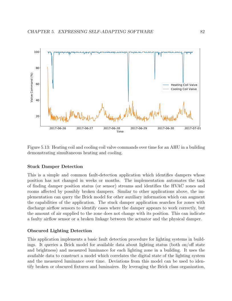
CHAPTER 5. EXPRESSING SELF-ADAPTING SOFTWARE 82
Figure 5.13: Heating coil and cooling coil valve commands over time for an AHU in a buildingdemonstrating simultaneous heating and cooling.
Stuck Damper Detection
This is a simple and common fault-detection application which identifies dampers whoseposition has not changed in weeks or months. The implementation automates the taskof finding damper position status (or sensor) streams and identifies the HVAC zones androoms affected by possibly broken dampers. Similar to other applications above, the im-plementation can query the Brick model for other auxiliary information which can augmentthe capabilities of the application. The stuck damper application searches for zones withdischarge airflow sensors to identify cases where the damper appears to work correctly, butthe amount of air supplied to the zone does not change with its position. This can indicatea faulty airflow sensor or a broken linkage between the actuator and the physical damper.
Obscured Lighting Detection
This application implements a basic fault detection procedure for lighting systems in build-ings. It queries a Brick model for available data about lighting status (both on/off stateand brightness) and measured luminance for each lighting zone in a building. It uses theavailable data to construct a model which correlates the digital state of the lighting systemand the measured luminance over time. Deviations from this model can be used to iden-tify broken or obscured fixtures and luminaires. By leveraging the Brick class organization,
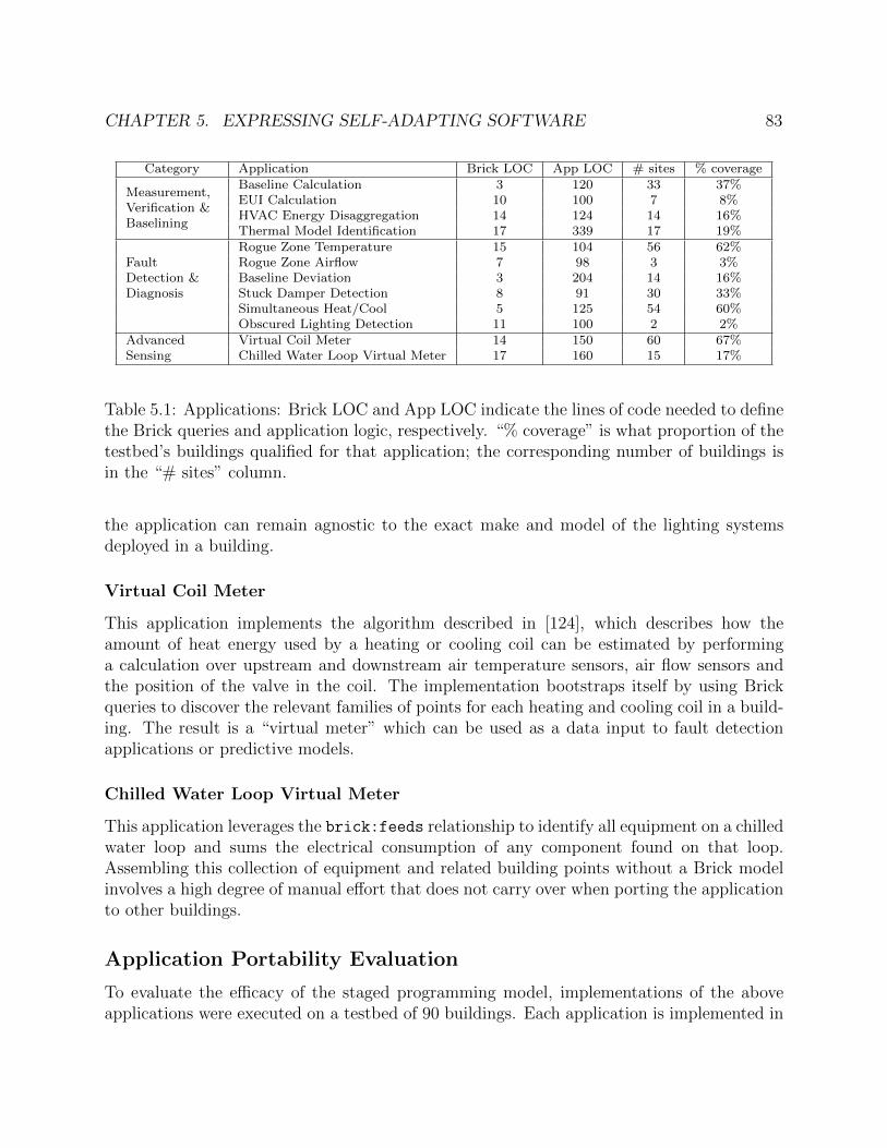
CHAPTER 5. EXPRESSING SELF-ADAPTING SOFTWARE 83
Category Application Brick LOC App LOC # sites % coverage
Measurement,Verification &Baselining
Baseline Calculation 3 120 33 37%EUI Calculation 10 100 7 8%HVAC Energy Disaggregation 14 124 14 16%Thermal Model Identification 17 339 17 19%
FaultDetection &Diagnosis
Rogue Zone Temperature 15 104 56 62%Rogue Zone Airflow 7 98 3 3%Baseline Deviation 3 204 14 16%Stuck Damper Detection 8 91 30 33%Simultaneous Heat/Cool 5 125 54 60%Obscured Lighting Detection 11 100 2 2%
AdvancedSensing
Virtual Coil Meter 14 150 60 67%Chilled Water Loop Virtual Meter 17 160 15 17%
Table 5.1: Applications: Brick LOC and App LOC indicate the lines of code needed to definethe Brick queries and application logic, respectively. “% coverage” is what proportion of thetestbed’s buildings qualified for that application; the corresponding number of buildings isin the “# sites” column.
the application can remain agnostic to the exact make and model of the lighting systemsdeployed in a building.
Virtual Coil Meter
This application implements the algorithm described in [124], which describes how theamount of heat energy used by a heating or cooling coil can be estimated by performinga calculation over upstream and downstream air temperature sensors, air flow sensors andthe position of the valve in the coil. The implementation bootstraps itself by using Brickqueries to discover the relevant families of points for each heating and cooling coil in a build-ing. The result is a “virtual meter” which can be used as a data input to fault detectionapplications or predictive models.
Chilled Water Loop Virtual Meter
This application leverages the brick:feeds relationship to identify all equipment on a chilledwater loop and sums the electrical consumption of any component found on that loop.Assembling this collection of equipment and related building points without a Brick modelinvolves a high degree of manual effort that does not carry over when porting the applicationto other buildings.
Application Portability Evaluation
To evaluate the efficacy of the staged programming model, implementations of the aboveapplications were executed on a testbed of 90 buildings. Each application is implemented in

CHAPTER 5. EXPRESSING SELF-ADAPTING SOFTWARE 84
Python. The testbed, which is described in Chapter 7, contains a Brick model and between6 months and 6 years of telemetry for each building.
Recall that there are two dimensions to the evaluation of the programming model: con-ciseness and portability. Measuring conciseness consists of counting the number of lines ofcode to implement each application; this number is split into configuration (the number oflines of code to express the SPARQL queries in the qualify step) and execution (the restof the application).
Measuring portability consists of counting the number of buildings in the testbed onwhich each application successfully ran without any changes; this proportion is labeled ascoverage. Due to differences in the availability of metadata and the subsystems present ineach building, not every application can achieve 100% coverage.
The result of the evaluation are summarized in Table 5.1. Applications with simplermetadata requirements (such as Rogue Zone Temperature and Basline Calculation) tend tohave higher coverage; this is because they rely on entities that are more likely to be includedin a Brick model. Likewise, applications which are very flexible in the kinds of metadatathat they can leverage — such as Virtual Coil Meter — can run on many buildings, butwill likely perform better (more accurate and robust predictions, for example) on buildingswhich have more metadata available.
On the other hand, applications like Rogue Zone Airflow and Obscured Lighting Detectionhave very low coverage. This is because Rogue Zone Airflow requires setpoint information,which is often not available in buildings, and Obscured Lighting Detection requires lightingmetadata. Because lighting systems are often separately installed from the BMS, whichusually manages HVAC systems in the kinds of buildings contained in the testbed, it can bedifficult to include metadata about the lighting system in the Brick model.
Future Evaluations
The ideal self-adapting programming model is one which minimizes the overhead of devel-oping a self-adapting application. “Overhead” incorporates both the development time ofthe application — a self-adapting application should ideally not take dramatically longer todevelop than a non-self-adapting version — as well as the cognitive load of the programmingmodel. The semantic web technology underlying the metadata model, while powerful, ismostly unfamiliar to most users and developers. An effective self-adapting programmingmodel should, where possible, reduce the need for users to be experts in first order logic,semantic web technologies, and other “implementation details” of how the metadata is ex-pressed. Studying the usability and efficacy of self-adapting programming models will involvedeveloping user studies which consult not just programmers but also building and facilitiesmanagers.

CHAPTER 5. EXPRESSING SELF-ADAPTING SOFTWARE 85
Figure 5.14: A BAS [84] representation of a building’s electrical, lighting, spatial and HVACsubsystems
5.4 Alternative Programming Models
Other models for programming portable applications are both present in the sensor network-ing literature and have emerged in the years since Brick was first published in 2016.
Macroprogramming [61, 106] is a family of programming models enabling high-level pro-grams to be distributed and executed over networks of potentially heterogeneous sensornodes. Most macroprogramming models incorporate a limited number of system primitiveswhich are implementable on a variety of sensor platforms. These system primitives can becomposed together into novel programs. The intellectual overlap between macroprogram-ming and self-adapting software is in the use of declarative expressions to specify what dataand computation is required. A platform then carries out the fulfillment of this specification;TinyDB [89] is a prime example of this approach. One significant difference between macro-programming and self-adapting software is that macroprogramming enforces a separationbetween the specification and implementation of the program. Users of a macroprogrammingsystem can remain agnostic to how the system primitives are implemented and executed;in contrast, the self-adapting programs above still require the user to write procedural codethat deals with the differences between deployment environments.
Earlier models for portable software for buildings was developed in Building ApplicationStack (BAS) [84], Building Operating System Services (BOSS) [39] and BuildingDepot [147].BAS established a novel portable programming model for analytics and control applicationsin buildings. BOSS established a suite of supporting services providing OS-like abstractions
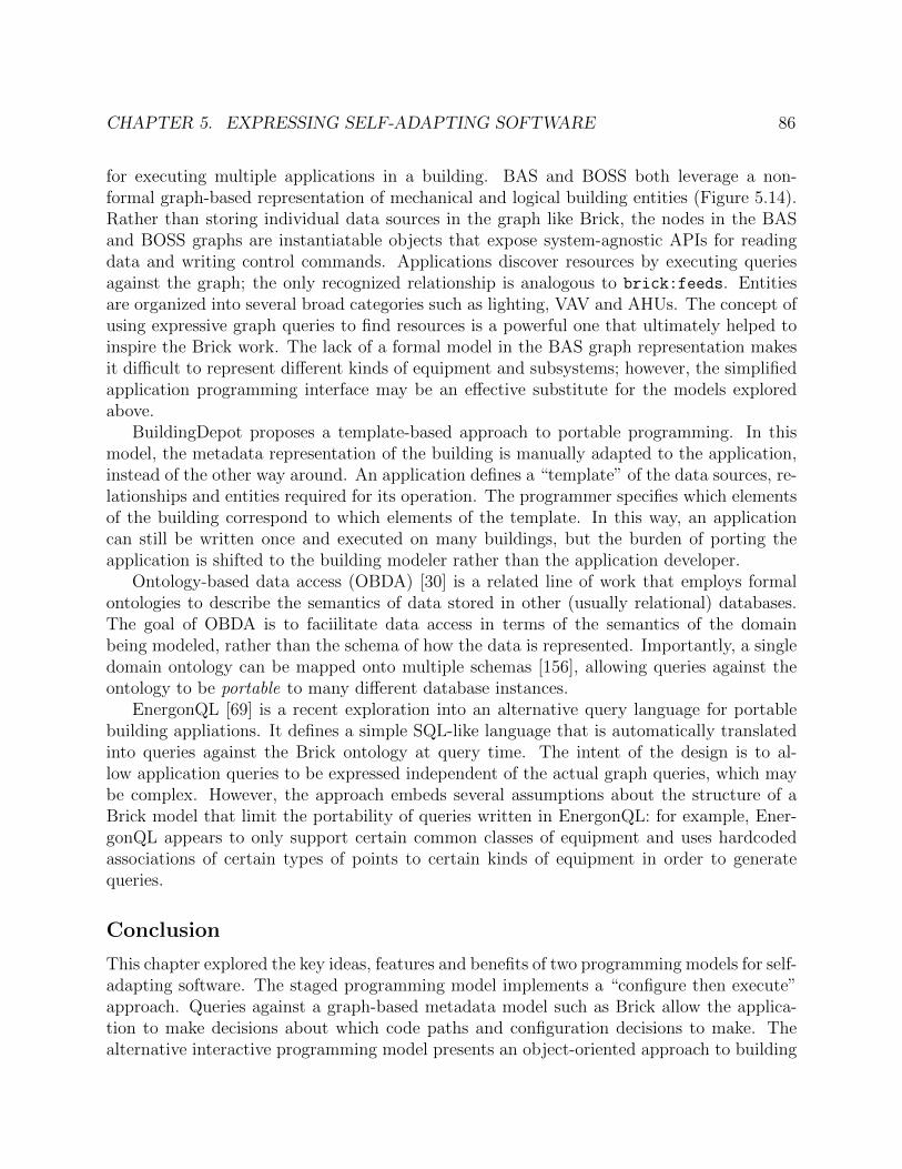
CHAPTER 5. EXPRESSING SELF-ADAPTING SOFTWARE 86
for executing multiple applications in a building. BAS and BOSS both leverage a non-formal graph-based representation of mechanical and logical building entities (Figure 5.14).Rather than storing individual data sources in the graph like Brick, the nodes in the BASand BOSS graphs are instantiatable objects that expose system-agnostic APIs for readingdata and writing control commands. Applications discover resources by executing queriesagainst the graph; the only recognized relationship is analogous to brick:feeds. Entitiesare organized into several broad categories such as lighting, VAV and AHUs. The concept ofusing expressive graph queries to find resources is a powerful one that ultimately helped toinspire the Brick work. The lack of a formal model in the BAS graph representation makesit difficult to represent different kinds of equipment and subsystems; however, the simplifiedapplication programming interface may be an effective substitute for the models exploredabove.
BuildingDepot proposes a template-based approach to portable programming. In thismodel, the metadata representation of the building is manually adapted to the application,instead of the other way around. An application defines a “template” of the data sources, re-lationships and entities required for its operation. The programmer specifies which elementsof the building correspond to which elements of the template. In this way, an applicationcan still be written once and executed on many buildings, but the burden of porting theapplication is shifted to the building modeler rather than the application developer.
Ontology-based data access (OBDA) [30] is a related line of work that employs formalontologies to describe the semantics of data stored in other (usually relational) databases.The goal of OBDA is to faciilitate data access in terms of the semantics of the domainbeing modeled, rather than the schema of how the data is represented. Importantly, a singledomain ontology can be mapped onto multiple schemas [156], allowing queries against theontology to be portable to many different database instances.
EnergonQL [69] is a recent exploration into an alternative query language for portablebuilding appliations. It defines a simple SQL-like language that is automatically translatedinto queries against the Brick ontology at query time. The intent of the design is to al-low application queries to be expressed independent of the actual graph queries, which maybe complex. However, the approach embeds several assumptions about the structure of aBrick model that limit the portability of queries written in EnergonQL: for example, Ener-gonQL appears to only support certain common classes of equipment and uses hardcodedassociations of certain types of points to certain kinds of equipment in order to generatequeries.
Conclusion
This chapter explored the key ideas, features and benefits of two programming models for self-adapting software. The staged programming model implements a “configure then execute”approach. Queries against a graph-based metadata model such as Brick allow the applica-tion to make decisions about which code paths and configuration decisions to make. Thealternative interactive programming model presents an object-oriented approach to building

CHAPTER 5. EXPRESSING SELF-ADAPTING SOFTWARE 87
self-adapting software that implicitly performs queries against the Brick model during execu-tion. This model, unlike the staged model, does not require users to have an understandingof the structure and contents of the metadata graph before the program is executed.
The staged programming model was evaluated by implementing 12 analytics applicationsthat were executed on a set of 90 buildings. 9 of the 12 applications were able to run onat least 15% of the buildings without any changes to application code or configuration.This demonstrates that self-adapting software brings real benefits and can be practicallyimplemented.

88
Chapter 6
Metadata Management forSelf-Adapting Software
Another flaw in the humancharacter is that everybodywants to build, and nobodywants to do maintenance.
Kurt Vonnegut Jr.
A critical challenge in realizing the vision of self-adapting software is how to maintain thesemantic metadata model over time. Cyberphysical software relies on a correct and up-to-date representation of the environment. However, cyberphysical environments are constantlyin a state of churn: physical equipment breaks or gets replaced, subsystems get updatedand physical spaces get remodeled. Effective management of semantic metadata requiresdetecting changes in the cyberphysical environment and incorporating those changes intothe metadata model which is available to self-adapting applications. This chapter focuseson methods and systems for producing and maintaining the semantic metadata model foran environment over time.
Two aspects of the metadata model will change over time: its content and its semantics.The content of the metadata model changes in response to the evolution of the environ-ment it models with respect to the scope of the model. For a metadata representation likeBrick, salient environmental changes include repairs, retrofits and remodels that affect therepresentation of equipment, controllers, networks and physical architecture.
The semantics of the metadata model are driven by evolution of the domain — for exam-ple, due to technological advancements — or evolution of the application — for example, ifthe ontology developers want to support new kinds of applications. While certain develop-ment practices such as semantic versioning1 can foster “backwards compatibility” between
1https://semver.org/

CHAPTER 6. METADATA MANAGEMENT FOR SELF-ADAPTING SOFTWARE 89
versions of an ontology, these simply place subjective constraints on how the metadata repre-sentation can be changed and do not provide a mechanism for using older or newer versions.Since its release in 2016, Brick has seen two major releases that changed the definition andnames of classes and reorganized the hierarchy [16, 51].
This chapter examines why and how changes in metadata models and representationsoccur over time in cyberphysical settings. It then formalizes and develops a technique forhandling changes in model content. This technique is implemented in a system, Shepherding,which handles changes in metadata model content over time and is demonstrated in thecontext of Brick models for evolving buildings. The chapter concludes with a brief discussionof how evolution in semantics may be handled.
6.1 Prior Work on Metadata Management
Managing changes in metadata content and semantics incorporates components of data in-tegration and schema evolution.
Data Integration and Record Linkage
Data integration is the process of consolidating heterogeneous data from many sources into asingle, “application-facing” representation. Architectures and techniques for data integrationdiffer in the coupling and mapping between data sources and the destination schema. Recentwork in data integration has favored data warehouses. Here, heterogeneous data sources arequeried indirectly through a “virtual database” which translates queries over a central schemato the schemas of individual data sources. The wrapper-mediator architecture is one exampleof this approach [56, 152]. Queries are executed against a mediator which has knowledge ofmany data sources which may contain data relevant to the query. The mediator forwardsqueries to wrappers — logical processes which interface directly with the data sources andrewrite the query to execute on the underlying schema.
However, in cyberphysical environments, different representations are often owned bydifferent stakeholders. This means that they are not consolidated into a single storagerepository nor are they readily available for consumption by automated tooling. In manycases, the source data have an unstructured form that does not facilitate querying — recallthe heterogeneous and unstructured labels detailed in Chapter 2. Extract-transform-load(ETL) pipelines are one mechanism for translating existing data sources into a more desirableform [144]. ETL pipelines extract data from existing data sources which may be local orremote, transform the data into the necessary structure and load the processed data into aunified database.
There are several classic data integration issues which are relevant to managing cyber-physical metadata. First, the semantics of different metadata representations must be han-dled. Different data sources are built with differing perspectives on a domain. Integrationof data sources must take into account the different meanings and organizations of the data

CHAPTER 6. METADATA MANAGEMENT FOR SELF-ADAPTING SOFTWARE 90
they contain. Often, the data semantics are implicit in the data schema and are not capturedin any formal manner. Systems like Mastro [30] and [87] describe source data using ontolo-gies in order to inform the data integration process with the semantics of the data beingintegrated. Establishing the mapping between many metadata sources and the destinationmodel can be time-consuming. Systems like [38] and [95] reduce the effort with a “pay-as-you-go” approach to schema mapping that focuses on only the data required by particularapplications.
Another issue is that of data representation. Different data sources may represent thesame items using different syntax, data structures and schemas. In particular, many sourcesof cyberphysical metadata are characterized by a lack of well-defined semantics. Lines of workon schema mapping [48] and schema matching [22] deal with the mechanics of transformingdata in one form to another. This includes aggregations, disaggregations, relabelings of dataand reorganizations of the schemas. An effective solution for integration of cyberphysicalmetadata should handle both structured and unstructured sources of metadata.
The final major issue is how to determine when two or more data sources refer to thesame object or entity under different names or with different descriptions. This is classicallyreferred to as record linkage or entity disambiguation [153]. Record linkage may be accom-plished through a variety of classic techniques such as string similarity or matching entitiesin different data sources by shared attributes. Newer techniques explore leveraging largeamounts of complex and related data [45] or reasoning through noisy or uncertain data [46].
Schema Evolution
The body of work on schema evolution focuses on how to better manage and automate theprocess by rewriting queries to execute on new schemas and transforming source schemas tofit a new schema. Many frameworks like Python’s Django [42] and Ruby’s ActiveRecord [13]provide tools for schema evolution, but focus on the migration of data and do not provideany mechanism for database administrators (DBAs) to reason about the semantic impactof the schema migration. Systems like [35], [23] and [21] provide greater degrees of automa-tion through high-level schema modification operators that assist DBAs in evaluating theimpact of a schema modification as well as performing the data transformation itself. Otherapproaches take the additional step of automatically transforming applications to matchchanging schemas [32].
Schema evolution research focuses on the structural aspects of schemas: the attributes,their names and datatypes, membership in tables, and integrity constraints between them.This approach ignores the issue of semantic integrity: how do the meaning and context ofattributes change over time and how do these changes affect the interpretation and usage ofthe data in a database?
[107] calls out this difference in the context of ontology evolution. Because an ontologyis an “explicit specification of a conceptualization of a [knowledge] domain”[107], changesin the domain, conceptualization and explicit specification may all incur changes in theontology. Existing approaches for ontology evolution [108, 136, 109] focus on managing

CHAPTER 6. METADATA MANAGEMENT FOR SELF-ADAPTING SOFTWARE 91
changes in the ontology itself and do not address how to interpret those changes when theontology describes attributes in an external table.
6.2 Extracting Semantic Metadata
One of the most time-consuming and error-prone aspects of managing semantic metadata iscreating the representation that can be accessed by software. This section focuses on howmetadata models such as Brick can be bootstrapped from existing digital representations ofthe environment. For a family of common metadata representations — recall BuildingSync,Haystack, gbXML and Modelica/CDL from Chapter 2 — a wrapper is developed whichis able to produce or infer Brick metadata from the underlying source. Wrappers are acomponent of a metadata integration architecture, which is able to combine the individualBrick models produced by each driver into a unified representation.
BuildingSync
BuildingSync is an XML-based schema for reporting energy-related properties of buildingsand their subsystems and coarse-grained relationships between them. The BuildingSyncwrapper produces Brick metadata from a BuildingSync document by mapping combina-tions of XML elements and attributes to Brick class definitions. The correspondence be-tween BuildingSync and Brick is expressed as a mapping from an XPath expression to aBrick class. For example, the BuildingSync auc:Chiller element aligns with the Brickbrick:Chiller class. If the auc:Chiller element contains a auc:ChillerType propertywith the value “Absorption”, then the wrapper can infer the more specific Brick class ofbrick:Absorption Chiller.
BuildingSync does not explicitly contain topological information about building sys-tems which could inform inference of Brick relationships. However, the limited numberof equipment types recognized by BuildingSync means it is feasible to infer some relation-ships based on the structure of the BuildingSync document and the types of the entities. Achild relationship between one XML element and another usually denotes a compositional(brick:isPartOf) relationship between the child and parent. One example of this is thenested relationship between the auc:Site and auc:Building BuildingSync elements. Otherinternal attributes such as auc:LinkedSystemID can associate components of a subsystemwith each other. At time of writing, the wrapper defines 27 direct mappings, primarily forlocations and equipment types.
There are a few challenges that must be addressed by the BuildingSync wrapper. Build-ingSync documents often represent collective properties of building systems and equipment— e.g. the number of absorption chillers, not how the individual chillers are connected— which limits the number of Brick relationships that can be derived. Also, by model-ing systems rather than components, BuildingSync models often lack descriptive labels forequipment and points.
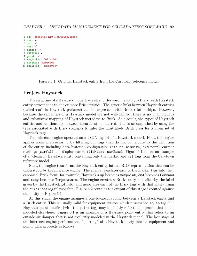
CHAPTER 6. METADATA MANAGEMENT FOR SELF-ADAPTING SOFTWARE 92
1 id: 'd83664ec RTU-1 OutsideDamper'2 air: X3 cmd: X4 cur: X5 damper: X6 outside: X7 point: X8 regionRef: '67faf4db'9 siteRef: 'a89a6c66'
10 equipRef: 'd265b064'
Figure 6.1: Original Haystack entity from the Carytown reference model
Project Haystack
The structure of a Haystack model has a straightforward mapping to Brick: each Haystackentity corresponds to one or more Brick entities. The generic links between Haystack entities(called refs in Haystack parlance) can be expressed with Brick relationships. However,because the semantics of a Haystack model are not well-defined, there is no unambiguousand exhaustive mapping of Haystack metadata to Brick. As a result, the types of Haystackentities and relationships between them must be inferred. This is accomplished by using thetags associated with Brick concepts to infer the most likely Brick class for a given set ofHaystack tags.
The inference engine operates on a JSON export of a Haystack model. First, the engineapplies some preprocessing by filtering out tags that do not contribute to the definitionof the entity, including data historian configuration (hisEnd, hisSize, hisStart), currentreadings (curVal) and display names (disMacro, navName). Figure 6.1 shows an exampleof a “cleaned” Haystack entity containing only the marker and Ref tags from the Carytownreference model.
Next, the engine transforms the Haystack entity into an RDF representation that can beunderstood by the inference engine. The engine translates each of the marker tags into theircanonical Brick form: for example, Haystack’s sp becomes Setpoint, cmd becomes Commandand temp becomes Temperature. The engine creates a Brick entity identified by the labelgiven by the Haystack id field, and associates each of the Brick tags with that entity usingthe brick:hasTag relationship. Figure 6.2 contains the output of this stage executed againstthe entity in Figure 6.1.
At this stage, the engine assumes a one-to-one mapping between a Haystack entity anda Brick entity. This is usually valid for equipment entities which possess the equip tag, butHaystack point entities (with the point tag) may implicitly refer to equipment that is notmodeled elsewhere. Figure 6.1 is an example of a Haystack point entity that refers to anoutside air damper that is not explicitly modeled in the Haystack model. The last stage ofthe inference engine performs the “splitting” of a Haystack entity into an equipment andpoint. This proceeds as follows:

CHAPTER 6. METADATA MANAGEMENT FOR SELF-ADAPTING SOFTWARE 93
1 :d83664ec brick:hasTag tag:Command . # cmd2 :d83664ec brick:hasTag tag:Damper .3 :d83664ec brick:hasTag tag:Outside .4 :d83664ec brick:hasTag tag:Point .
Figure 6.2: Intermediate RDF representation of the Haystack entity; Haystack software-specific tags (e.g. cur, tz) are dropped.
1 :d83664ec_point brick:hasTag tag:Damper .2 :d83664ec_point brick:hasTag tag:Command .3 :d83664ec_point a brick:Damper_Position_Command . # inferred4 :d83664ec_equip brick:hasTag tag:Air .5 :d83664ec_equip brick:hasTag tag:Outside .6 :d83664ec_equip brick:hasTag tag:Damper .7 :d83664ec_equip a brick:Outside_Damper . # inferred8 :d83664ec_point brick:isPointOf :d83664ec_equip . # inferred9 :d83664ec_point brick:isPartOf :d265b064 # inferred
Figure 6.3: Brick inference engine splits the entity into two components: the explicit pointand the implicit outside damper equipment.
First, the inference engine attempts to classify an entity as equipment. The enginetemporarily replaces all point-related tags from an entity – Point, Command, Setpoint,Sensor – with the Equipment tag, and finds Brick classes with the smallest tag sets thatmaximize the intersection with the entity’s tags. This corresponds to the most generic Brickclass. In the running example, the inference engine would transform the entity in Figure 6.2to the tags Damper, Outside and Equipment. There are 12 Brick classes with the Damper
tag, but only one class with both the Damper and Outside tags; thus, the minimal Brick classwith the maximal tag intersection is Outside Air Damper. If the inference engine cannotfind a class with a non-negligible overlap (such as the Equipment tag), then the entity is notequipment.
Secondly, the inference engine attempts to classify the entity as a point. In this case, theengine does not remove any tags from the entity, and finds the Brick classes with the smallesttag sets that maximize the intersection with the entity’s tags. In the running example, theminimal class with the maximal tag intersection is Damper Position Command.
Figure 6.3 contains the two inferred entities output by this methodology. In the casewhere a Haystack entity is split into an equipment and a point, the Brick inference engineassociates the two entities with the brick:isPointOf relationship (line 10 of Figure 6.3).Additionally, the inference engine translates Haystack’s Ref tags into Brick relationshipsusing the simple lookup-table based methodology established in [15]. The inference engineapplies these stages to each entity in a Haystack model; the union of the produced entities

CHAPTER 6. METADATA MANAGEMENT FOR SELF-ADAPTING SOFTWARE 94
and relationships constitutes the inferred Brick model.
Modelica/CDL
Modelica and CDL models consist of a set of connected objects. This linked structureclearly identifies entities and the relationships between them, which closely resembles thestructure of a Brick model. Modelica objects have classes, which supports the develop-ment of a mapping between Modelica classes and Brick classes. For example, every in-stance of the Modelica class Buildings.Fluid.Sensor.Temperature can be translated intoa brick:Temperature Sensor entity.
The wrapper takes as input a JSON export of a Modelica/CDL model [98]. The wrappertreats each instance of a Modelica model in the document as a Brick entity, and assigns aBrick class to entities whose class is defined in the Modelica Buildings Library [150]. Toinfer relationships between these entities, the wrapper examines the ports for each Modelicainstance; these are connected by connect statements to other instances of Modelica mod-els. These links between objects in a Modelica model can inform the choice of sequential(brick:feeds) and compositional (brick:hasPart) relationships between their correspond-ing Brick entities.
There are a few challenges in producing Brick metadata from a Modelica/CDL model.First, because Modelica is a general modeling language, it is possible for models to describebuildings using classes unknown to the wrapper. The wrapper establishes mappings for manyof the common classes in the Modelica Buildings Library [150], but there is no guaranteethat a Modelica model will use these classes. Second, due to Modelica’s model encapsulation,contextual properties, i.e., how the objects relate to a larger system, need to be inferred. Forexample, for an instance of the class Buildings.Fluid.Sensor.Temperature, where it islocated (e.g. exhaust air, return air, entering water, leaving water) need to be inferred fromthe system that contains the sensor.
gbXML
Wrappers for BIM can produce Brick metadata about individual components, but inferringcontextual relationships between those components is more difficult. Because BIM modelsfocus on the geometry and physical connections of spaces and equipment, the representationsmay lack or obscure the contextual information needed during the operations and mainte-nance stages of the building. For example, although several versions of the IFC standardenumerate possible physical and contextual properties of fans, these details may not be in-cluded in an IFC model or must be inferred by traversing the connections between otherelements in the model. Previous work also indicates that little Brick metadata can be in-ferred from IFC models [85]. This is due in part to the complex and generic schema ofIFC in which related pieces of information are often separated by many intermediate ob-jects [44]. In contrast, gbXML models contain more explicit contextual information such as

CHAPTER 6. METADATA MANAGEMENT FOR SELF-ADAPTING SOFTWARE 95
Figure 6.4: The distribution of the number of triples inferred per entity for each wrapper.
the <AirLoop> element, which groups related HVAC equipment together. This permits theinference of more metadata such as sequential and compositional relationships.
A significant challenge for the production of Brick metadata from a BIM model is vari-ability in how BIM models are expressed. BIM standards are designed to be flexible andextensible, which can result in a lack of consistency and thus interoperability [49, 99]. Rep-resenting BIM models using semantic web technology will allow the wrapper to more easilyvalidate and inspect the BIM metadata, which may result in a more complete Brick metadatamodel [115].
Evaluation of Wrapper Performance
To characterize the behavior and performance of the wrappers, a set of publicly availablemetadata models from a variety of metadata representations was assembled. The models donot cover the same set of buildings, but the population still enables empirical measurementof the availability of Brick metadata in those representations.
Figure 6.4 and Figure 6.5 illustrate the number of Brick triples inferred per entity andthe total number of triples inferred by each wrapper, respectively. The reason for thesedistributions is due to fundamental differences between the metadata representations andBrick, and implementation details of the wrappers.
The amount of Brick metadata obtained from a BuildingSync model is limited comparedto what can be inferred from gbXML, Modelica or Project Haystack models (Figure 6.5).This is due to a difference in scope: BuildingSync describes properties and performancecharacteristics of building systems, rather than the individual components and relationshipsfound in other metadata sources. As a result, a BuildingSync model may be a better exporttarget from a unified Brick model.
Within this population of sites, Modelica models contain the most Brick metadata perentity, but do not contain as many entities as Haystack models. The BuildingSync andgbXML wrappers only produce a few triples per entity: usually the type of the entity anda topological reference to a few other entities. Haystack models contain more entities andmore Brick metadata per entity than metadata sources for energy audits and BIM. This is

CHAPTER 6. METADATA MANAGEMENT FOR SELF-ADAPTING SOFTWARE 96
Figure 6.5: The distribution of the total number of triples inferred by each wrapper. Notethe log-scale on the X axis
an intuitive result because the Haystack metadata representation is the most similar to Brickin terms of its intended use cases, and thus presents much of the same metadata (if in a lessstructured form).
6.3 Metadata Management Over the Building
Lifecycle
Effective management of a metadata model which enables self-adapting applications requireskeeping the metadata model “in sync” with the state of the cyberphysical environment inwhich applications will be deployed. This section examines the evolution of a building overtime as a case study of handling changes in a cyberphysical environment while enablingself-adapting software.
In the building context, updates to the metadata model are informed by observing andderiving updates from other digital representations of the same environment. Many differentdigital representations of a building are typically produced over the course of its lifecycle.These representations contain — in some form — the metadata required to support differ-ent operational stages and treatments of the building, from initial planning and design, toconstruction and commissioning, through operations, audits, retrofits and repairs.
Figure 6.6 describes at a high level the different metadata representations that may be cre-ated and leveraged over the lifecycle of a building. The design phase of a building, conductedusing BIM, may produce IFC or gbXML models that are used during the construction phaseof the building. During construction, this metadata may be used in conjunction with CDLdescriptions of the building’s sequence of operations to configure the BMS. UnstructuredBMS metadata may be captured in a Brick or Haystack model to facilitate data analysisand to perform predictive maintenance. Other metadata sources such as BuildingSync maybe used to conduct energy audits before and after retrofits and repairs, which themselves mayrely upon CDL, IFC or gbXML representations of the building’s control loops and assets.

CHAPTER 6. METADATA MANAGEMENT FOR SELF-ADAPTING SOFTWARE 97
CommissioningConstructionDesign Operation
Maintenance
Audit
IFC, gbXML, CDL, Modelica
IFC, gbXML, CDL
BMS,Haystack, CDL, Brick
Brick, Haystack
BuildingSync
Small Retrofit
Large Retrofit, Renovation
IFC, gbXML
Figure 6.6: Different tools for different stages: Many different metadata standards andtechnologies are applied over the course of a building’s lifecycle, but are relatively siloed andthus non-interoperable.
Different representations communicate different perspectives on the same building: themetadata required to support the construction of a building is different than the metadatarequired to manage schedules and control sequences. Therefore, it is possible to detectchanges in many different aspects of the environment by observing many different metadatarepresentations. There are several desirable properties of this approach:
• It is possible to bootstrap the creation of the metadata model from existing digitalrepresentations, lowering the initial cost of building out the model, which can be anon-trivial investment [27].
• Because the metadata model’s intent is to enable self-adapting software, it does notneed to enable other kinds of use cases that are traditionally served by other technolo-gies. This preserves any existing investments and makes the proposed system easier toadopt.
• Many other digital representations are “dropped” or left unmaintained after the op-erational stage of the building for which they were created is over [114]. Providing ause for these representations — enabling self-adapting software — incentivizes theirmaintenance.
Working with several metadata representations poses challenges for effective manage-ment. Differences in the semantics, structure and syntax of models generally result in alack of interoperability [158] between them. This limits the extent to which metadata fromone stage of a building’s lifecycle can contribute to the metadata for another stage. Therehave been previous attempts to increase information sharing and reuse between stakeholdersthough a shared knowledge base [83] or by centralizing all data in a BIM model [158]. [139]demonstrates the semi-automated configuration of a building automation system by export-ing BACnet objects from the BIM, enabling the exchange of information across the design,construction and operational stages of a building. However, because representations such

CHAPTER 6. METADATA MANAGEMENT FOR SELF-ADAPTING SOFTWARE 98
.xml
.xml
.json
.xml.xml
.json.json
Figure 6.7: Overview of the proposed approach: wrappers interface directly with existingmetadata sources stored in local file systems, or accessed via file shares or networked services.Wrappers continuously publish inferred Brick metadata to a central server, which producesa unified model.
as BIM are not appropriate for self-adapting software, the approach developed below dealswith how to lift existing metadata representations into a Brick model.
Specifically, this section develops a protocol and algorithm for performing continuousintegration of heterogeneous metadata representations into a single metadata model whichcan be used for self-adapting applications. The protocol and algorithm are incorporatedinto a functional system which has been evaluated on several real metadata sources for tworepresentative buildings.
Architecture for Continuous Metadata Integration
The proposed system adapts existing data integration architectures and techniques to theproblem of lifting heterogeneous metadata sources about buildings into an ontology-definedstructure that serves as a canonical representation.
Figure 6.7 represents the architecture of the ETL data integration system. On the farleft of the figure are existing metadata representations of the building; these may exist in astructured or unstructured form and support a variety of legacy applications. A wrapper,described above, is a software process that interfaces with one or more of the existing meta-data representations and produces a Brick model of the metadata contained within. Forstructured or standardized metadata sources such as BuildingSync and gbXML, the wrap-per may perform a direct translation of the source’s concepts and structures to Brick. For

CHAPTER 6. METADATA MANAGEMENT FOR SELF-ADAPTING SOFTWARE 99
less structured and more ad-hoc sources such as Haystack and BMS labels, a wrapper mayrequire a statistical or heuristic-based approach to inferring Brick metadata. It is the jobof the wrapper to continually monitor the content of the underlying metadata source andto produce up-to-date Brick models in a timely manner. The architecture places no otherrequirements for how Brick metadata must be produced or inferred.
Wrappers report inferred Brick metadata to an integration server by means of a synchro-nization protocol. The protocol implements a simplified git-style source control systemwhich ensures that the integration server has the most up-to-date Brick metadata from eachmetadata source. The protocol operates in a push-based manner: wrappers report updatedmetadata when it is available. A push-based mechanism is preferable because the Brick in-ference process implemented by the wrapper may require human input that is not availableon-demand.
The integration server is a logically centralized process that assembles Brick metadatafrom a collection of wrappers and integrates them into a unified Brick model which is madeavailable for applications. Because different metadata sources are created at different stagesof the building and by independent stakeholders, the Brick metadata produced by the wrap-pers is likely to contain disagreements and inconsistencies, or may simply be out of date. Toaddress this issue, the integration server incorporates a novel reconciliation algorithm—analogous to the “merge” operation in git—that attempts to resolve the differences betweenthe metadata reported by the wrappers.
The architecture decouples the tasks of inferring Brick metadata from a particular sourceand integrating multiple sources of Brick metadata into a unified model. This establishesa common platform for Brick metadata inference research and allows existing and futuremethods to be used together. For example, inference methods such as [27] and [82] thatoperate on ad-hoc metadata representations can be adapted to the protocol.
Formalism of Brick Metadata Integration
The following definitions formalize the behavior of the wrappers, synchronization protocoland reconciliation algorithm described above.
A Brick model is a directed graph in which nodes are “entities” (physical, virtual, logicalthings and concepts) and edges are relationships between entities. Brick models are handilyexpressed in the RDF data model, which defines a graph as a set of triples : 3-tuples ofsubject (node), predicate (edge), object (node).
A metadata source Si corresponds to a set of metadata models mti indexed by a unique
timestamp t. A wrapper Wi is a function which produces a set of entities for a particularmetadata model:
Wi(mti)→ {et1, et2, . . . , etn} (6.1)
where etj is described by a set of fields called a record. Each record includes a set of triplesdescribing the entity, given by T (etj). Together, the triples produced by a wrapper constitutea Brick model Gt
i for a given metadata source and timestamp. The content of the Brick model
CHAPTER 6. METADATA MANAGEMENT FOR SELF-ADAPTING SOFTWARE 100
1 {"id": "RTU-1",2 "raw": {3 "content": "<auc:Delivery ID=\"RTU-1\">4 <auc:DeliveryType>5 <auc:CentralAirDistribution>6 <auc:AirDeliveryType>Central fan</auc:AirDeliveryType>7 <auc:FanBased>8 <auc:CoolingSupplyAirTemperature>73</auc:CoolingSupplyAirTemperature>9 </auc:FanBased>
10 </auc:CentralAirDistribution>11 </auc:DeliveryType>",12 "encoding": "XML"},13 "source": "BuildingSyncWrapper",14 "source_version": "2.1.0",15 "timestamp": "2020-07-16T20:02:50",16 "protocol_version": "1.0.0",17 "triples": [["http://example.com/building#RTU-1",18 "http://www.w3.org/1999/02/22-rdf-syntax-ns#type",19 "https://brickschema.org/schema/Brick#Rooftop_Unit"]]}
Figure 6.8: Example record published by the BuildingSync wrapper, showing the originalmetadata (raw) and the inferred Brick metadata (triples).
representing metadata from source i at time t is given by
Gti =
n⋃j=1
T (etj) (6.2)
The task of the reconciliation algorithm is to combine the set of Brick models producedby each wrapper into a single unified Brick model. The input to the reconciliation algorithmis the set of entities E from the latest metadata model for each of m sources
E =m⋃i=1
Wi(mtmaxi ) (6.3)
where tmax is the timestamp of the most recent model for metadata source i.
Metadata Synchronization Protocol
Wrappers update the integration server with the latest Brick metadata from a specific sourcevia the metadata synchronization protocol. The metadata synchronization protocol decou-ples the method of inferring or producing Brick metadata from how that metadata becomesintegrated into the authoritative model. This allows the proposed system to incorporate newmetadata sources and novel methods of inferring Brick metadata.
As part of the protocol, each wrapper presents the inferred Brick metadata accordingto a metadata profile. The profile is a structured representation of the Brick metadata

CHAPTER 6. METADATA MANAGEMENT FOR SELF-ADAPTING SOFTWARE 101
produced by the wrapper at a given time and is expressed as a set of HTTP resources. Theroot resource (/) holds a list of entity ids with associated Brick metadata for the currentmetadata model, and a timestamp representing the version of that metadata model. Therecord resources (/record/<id>) hold the record associated with a given entity id. A recordcontains the following fields:
• id: a name or other identifier for the entity, as given by the metadata source
• raw: identifies the encoding (e.g. JSON, XML) and content of the original metadatathat defined this entity. May contain additional metadata not expressed in Brick
• source: identifies the metadata source
• timestamp: denotes the time at which the metadata source was read to produce thecurrent metadata model
• triples: a list of RDF triples defining the Brick metadata for the entity
The timestamp field constitutes the version of the metadata model and is updated onlywhen the model or wrapper changes.
Figure 6.8 contains an example of a BuildingSync record for an HVAC delivery systemnamed “RTU-1”. Note that the original XML element contains additional metadata notconveyed in the produced Brick triples.
The content of the profile is synchronized with the integration server over the protocol.The protocol operates over HTTP and consists of two request-response actions: check andsync.
A check is an HTTP GET which asks the server for the latest known version of metadatafrom a particular source, and the number of records at that version. The server responds withthe version as a timestamp and an integer representing the number of records. By comparingthis information with the latest local version and corresponding number of records, thewrapper can determine if the server has a complete copy of the most recent Brick metadatafrom the wrapper. If the server timestamp is older than the local timestamp, or the numberof server records at the latest timestamp is less than the number of local records, the wrapperperforms a sync.
A sync is an HTTP POST of the list of records for the most recent version of themetadata model to the integration server, These records must contain the same versiontimestamp, which allows the set of records to span more than one HTTP POST while stillbeing associated with the same version of the metadata model.
The server saves all records in a local database. When the server performs the reconcilia-tion algorithm to produce a unified metadata model, it by default only considers the recordscorresponding to the most recent timestamp (version) per source. By extension, the servercan also produce a unified metadata model for any point in the Brick model’s history. Thisallows applications to access the history of changes in a building, but through the interface of

CHAPTER 6. METADATA MANAGEMENT FOR SELF-ADAPTING SOFTWARE 102
Entity: e1Triples: <e1,p,o> <e1,p,o> <e1,p,o>
Entity: e1Triples: <e1,p,o> <e1,p,o> <e1,p,o>
Entity: e1Triples: <e1,p,o> <e1,p,o> ...
e1Entity: e1Triples: <e1,p,o> <e1,p,o> <e1,p,o>
Entity: e1Triples: <e1,p,o> <e1,p,o> <e1,p,o>
Entity: e3Triples: <e3,p,o> <e3,p,o> ...
e1,e2,e3,e4,e5,e6,...
e1e3
e6
e6
e4
Entity: e1Triples: <e1,p,o> <e1,p,o> <e1,p,o>
Entity: e1Triples: <e1,p,o> <e1,p,o> <e1,p,o>
Entity: e5Triples: <e5,p,o> <e5,p,o> ...
Gj
Figure 6.9: The phases of the reconciliation algorithm. The latest Brick metadata (far left)is stored by the integration server.
a standardized, unified representation rather than an ad-hoc collection of diverse metadatasources.
The triples field can contain arbitrary Brick metadata to be relayed to the server.Typically this involves type information (vav1 is a brick:VAV), system composition infor-mation (vav1 is downstream of ahu1), telemetry association (vav1 has temperature setpointtemp sp1) and location information (tstat1 is in Room 410). The triples may also defineextensions to the Brick ontology, such as to describe additional properties of an unusualdevice or point. The union of all triples in all triples fields for all records constitutes theBrick model for the wrapper (Gtmax
i above).
Reconciliation of Multiple Brick Models
In order to produce a unified Brick model usable by applications, the Brick models producedby each wrapper must be merged together. This requires reconciling the differences betweeneach of the Brick models: entities may be named differently and have different associatedtypes and metadata. Reconciliation must be performed continuously in order to accountfor changes in the underlying metadata sources arising from evolving representations andenvironments. This subsection presents a reconciliation algorithm that extends existingrecord linkage techniques to graph-based semantic metadata and enforces the logical andsemantic validity of the resulting unified model.
Figure 6.9 illustrates the major phases of the reconciliation algorithm. First the mostrecent Brick models for each source are loaded from the integration server, having beendeposited there by the wrappers. Then, the algorithm finds clusters of entities such thatall entities in the cluster correspond to the same logical, virtual or physical instance (the“record linkage” stage in Figure 6.9). For each cluster, the algorithm produces the graphwhich is the union of all Brick metadata associated with the entities in that cluster andvalidates that the new graph is logically and semantically sound (the “graph union” stagein Figure 6.9).. Formally, each cluster of entities cj has an associated metadata graph Gj

CHAPTER 6. METADATA MANAGEMENT FOR SELF-ADAPTING SOFTWARE 103
which is the union of all the associated triples for entities in that cluster:
Gj =⋃ei∈cj
T (ei) (6.4)
The clustering is successful and the algorithm terminates if the metadata graph Gj satisfiesa set of constraints and checks.
The algorithmic processes for each stage are described in detail below.
First Phase: Record Linkage
The record linkage stage takes as input the most recent metadata records for each metadatasource known to the integration server and outputs a set of clusters. The stage applies tworecord linkage techniques on the metadata records: string matching and type alignment.
String matching calculates edit distance between entity labels to produce clusters of enti-ties. The name of an entity can be derived from string-valued properties such as rdfs:label,or the URI of the entity if no string-valued properties are found. The goal of this step is touse the semantic information sometimes encoded in entity labels as one heuristic for link-ing [27]. Due to different naming conventions between metadata sources, there can oftenbe greater similarity scores between entities from the same source than between entities ofdifferent sources. The algorithm assumes that all entities reported by a metadata source aredistinct and only clusters entities from different metadata sources.
Type alignment leverages semantic information from the proposed types of each entityto do type-aware clustering. The algorithm identifies all entities with a Brick class andassociates with each entity all Brick classes which are equal to or are superclasses of itsgiven type. If two or more sources have the same number, k, of entities of a given type,the algorithm produces k clusters containing one entity from each source with the highestpairwise similarity between their names. The clusters produced by this second step are addedto the set of clusters produced by the first step.
Second Phase: Graph Union
The second phase of the algorithm takes as input the clusters of entities from the firstphase and builds and validates the graphs formed by merging their associated triples. Foreach cluster, the algorithm produces the graph G using the formula in Equation 6.4. Thealgorithm also adds statements to the Brick model to merge the different identifiers for thesame entity (this uses the owl:sameAs property).
Unlike many other metadata sources, Brick is built over formal logic. This allows con-tinuous validation of a Brick model as metadata is added to it, which allows the algorithmto produce a logically valid model. The logical validation is implemented by a process calleda reasoner, which also generates logical consequences of the statements in a Brick graph(the reasoning process is described in more detail in Chapter 7). The reasoner examinesthe graph Gj for each cluster and produces a set of logical exceptions. These exceptions

CHAPTER 6. METADATA MANAGEMENT FOR SELF-ADAPTING SOFTWARE 104
1 # BuildingSync: ahu-12 bldg:bsync-ahu-1 rdf:type brick:Air_Handling_Unit ;3 rdfs:label "AHU-1" .4 # BuildingSync: main-meter5 bldg:bsync-meter rdf:type brick:Building_Power_Meter ;6 rdfs:label "main-meter" .7
8 # Haystack: rtu-19 bldg:ph-rtu-1 rdf:type brick:Rooftop_Unit ;
10 rdfs:label "RTU 1" ; brick:hasPoint bldg:oat-1 .11 # Haystack: main-meter12 bldg:ph-meter rdf:type brick:Power_Meter ; rdfs:label "Main Meter" .
Figure 6.10: Example Brick metadata produced by BuildingSync and Project Haystackwrappers. The rdfs:label property denotes the original name or identifier of the entity inthe metadata source.
1 bldg:rtu-1 rdf:type brick:Rooftop_Unit ; brick:hasPoint bldg:oat-1 .2 bldg:meter rdf:type brick:Building_Power_Meter .
Figure 6.11: The inferred unified metadata model for the triples in Figure 6.10. The mostspecific type is chosen for each entity, and that associated properties are carried through.
indicate that either the entities in the cluster are not equivalent, or the metadata associatedwith those entities is incorrect. Examples of exceptions include incompatible types (e.g. if acluster contains entities with disjoint types), incompatible relationships (e.g. if the values ofan entity’s properties and relationships do not match associated constraints) and semantic“sniff tests” which are qualities of the Brick graph that are not logical violations but mayindicate deeper issues. The primary example of the latter is an entity’s types should all besubclasses or superclasses of each other.
When exceptions occur, the algorithm can optionally re-cluster entities using more se-lective thresholds, or, as in the implemented prototype, by requesting human input on thefailing cluster. The algorithm then repeats the graph union step. These steps are iterateduntil no exceptions are logged, after which all of the cluster-produced graphs are merged intoa single graph. The algorithm validates the unified graph; if this passes, the unified graphis returned as the authoritative metadata model.
Human-aided Disambiguation
When the algorithm logs exceptions for the entities in a given “bad” cluster, the algorithmcan ask for external input on how to proceed. First, the algorithm asks if it should split
CHAPTER 6. METADATA MANAGEMENT FOR SELF-ADAPTING SOFTWARE 105
the bad cluster into two or more smaller clusters; this can be performed automatically byadjusting clustering hyperparameters or manually by specifying the new clusters explicitly.If reclustering occurs, then the algorithm begins another iteration of the graph union phaseabove using the new clusters.
If reclustering does not occur for a “bad” cluster, then the algorithm asks for manualresolution of the graph contents before proceeding to the next cluster. This typically involveschoosing which Brick class to assign to a group of entities, but may also require editingproperties and relationships of entities. The algorithm saves the results of manual resolutionso they can be applied during future runs of the reconciliation algorithm.
The reconciliation process can use human feedback to learn how to automatically cluster,classify and disambiguate entities as well as reduce the amount of manual resolution needed.Although this has not been implemented in the current proof-of-concept, the continuousintegration architecture can support active learning techniques such as [27].
Reconciliation Example
The behavior of the algorithm can be illustrated with an example of merging the metadatafrom Haystack and BuildingSync models for a building. The wrappers for these two sourcesproduce the Brick metadata listed in Figure 6.10. The algorithm begins by clustering theentities. The string-matching phase places bldg:bsync-meter and bldg:ph-meter intothe same cluster because their labels are sufficiently similar. The bldg:bsync-ahu-1 andbldg:ph-rtu-1 entities are not grouped because the labels are too dissimilar.
The type-aware phase examines the Brick-defined classes for the remaining entities. Usingthe Brick ontology, the algorithm infers that because brick:Air Handling Unit is a super-class of brick:Rooftop Unit, each source has metadata for one air handling unit. Becauseeach source has the same number of instances of that type, the algorithm clusters thoseentities by label similarity. This results in bldg:bsync-ahu-1 and bldg:ph-rtu-1 beingclustered. The difference in specificity between the original sources is due to the fact thatBuildingSync does not differentiate between subclasses of air handling units, but Haystackdoes.
The algorithm proceeds by unifying the triples for the entities in each cluster and validatesthe logical and semantic soundness of the resulting graph. In this simple example, the algo-rithm only needs to verify that the types of each pair of entities are compatible. This is true:brick:Air Handling Unit is a superclass of brick:Rooftop Unit and brick:Power Meter
is a superclass of brick:Building Power Meter. Finally, the two graphs are merged into asingle Brick model (Figure 6.11).
The reconciliation algorithm and metadata integration architecture are implemented ina fully functional prototype. This allows the evaluation of the approach on a set of real andartificial sites.

CHAPTER 6. METADATA MANAGEMENT FOR SELF-ADAPTING SOFTWARE 106
Site Name Metadata Source % Contributed Unique Model Size (Triples) # manual interventions
CarytownHaystack 32.9% 100%
280 0BuildingSync 20% 100%
DOE Medium OfficeHaystack 31.9% 100%
1,698 4Modelica 41.9% 98.2%BuildingSync .8% 98.5%
Table 6.1: The results of merging multiple metadata models for two different sites, showingthe diversity of the metadata available between the available metadata sources. The %Contributed percentages do not add up to 100% because the rest of the graph consists ofinferred metadata not contained in any particular model.
Evaluation of Integration Server
The reconciliation algorithm and integration server have been realized in a Python imple-mentation. The server exposes the API endpoints required of the metadata synchronizationprotocol and logs all sync messages received from wrappers in a SQLite database. The triplesin these messages, which contain the inferred Brick metadata from each wrapper, are insertedinto a dedicated table and indexed by their metadata source and timestamp. This allowsthe definition of a SQL View that contains the most recent triples for each wrapper, whichis used as input to the reconciliation algorithm. The server incorporates Allegrograph’s rea-soner implementation to perform the required logical validation of the Brick metadata [55].The server also embeds an in-memory instance of HodDB [50] to support application queriesagainst Brick metadata.
Table 6.1 contains the results of reconciling the Brick metadata from each source foreach site. The % Contributed column contains the proportion of triples in the unified modelthat were contributed by each source; this includes redundant triples. The Unique columncontains the proportion of triples in the unified model that are unique to each source.
Although there are only a few sites and models, it is possible to observe some generalbehavior about the metadata extracted from the available wrappers. First, the metadatafrom Haystack and BuildingSync wrappers are mostly complementary and there is littleoverlap between them. This aligns with the respective scopes of each metadata source:BuildingSync describes holistic properties of systems that may not be covered by ProjectHaystack models (at least in a standard way). Secondly, Modelica wrappers provide moreBrick metadata than Haystack wrappers: a Modelica/CDL model can produce a significantportion of the Brick metadata for a building. This aligns with the detailed treatment ofHVAC systems found in Modelica models compared with the coarse-grained modeling foundin Haystack.
For all sites, the metadata common to all wrappers was very low. This is to some extentdue to the completeness of the wrappers at time of writing, but is also limited by the differentlevels of detail and different perspectives of a building that are communicated by differentmetadata sources. The metadata contributed from each wrapper was almost completely

CHAPTER 6. METADATA MANAGEMENT FOR SELF-ADAPTING SOFTWARE 107
unique: even though there is some overlap in the entities described by each wrapper, itis rare for two wrappers to produce Brick metadata at the same level of detail or levelof completeness. For example, one sensor was identified as a brick:Flow Sensor by theModelica wrapper and a brick:Return Air Flow Sensor by the Haystack wrapper.
Discussion
The development and evaluation of the proof-of-concept implementation demonstrates thatintegrating metadata from many different sources is not only practical, but also yields aricher and more complete representation than any individual source. The resulting unifiedmetadata model enables self-adapting applications.
The metadata synchronization protocol successfully decouples the tasks of inferring Brickmetadata from a particular source and integrating multiple sources of Brick metadata intoa unified model. This establishes a common platform for Brick metadata inference research;for example, inference methods such as [27] and [82] that operate on ad-hoc metadata rep-resentations can be adapted to the protocol. This permits direct comparison of the Brickmetadata produced by different methods, and eases the integration of these methods withother wrappers. The protocol also offers a clear path for future metadata standards suchas ASHRAE’s 223P [8] to support or integrate with Brick. Future work will develop theexisting wrappers to deliver more complete and accurate Brick metadata, and implementadditional wrappers that operate on historical telemetry and unstructured data like BMSlabels.
Experiences with the reconciliation algorithm demonstrate that the extension of recordlinkage techniques to support semantic metadata graphs can successfully produce usefulBrick models. Due to the lack of descriptive labels, record linkage using type alignment wasmuch more effective than string matching for producing clusters of entities. In particular,autogenerated labels in Haystack and Modelica models caused a number of false positiveswhen using string matching. Despite these difficulties, the algorithm was able to detect theresulting semantic issues in the merged model by using the Brick ontology. Future work willaugment the reconciliation approach with active learning capabilities that can apply humaninput to automatically perform the required clustering and disambiguation.
6.4 Metadata Management Over Changing Semantics
The structure and semantics of metadata representations also change over time and mustbe managed. These changes are driven by churn in the domain being modeled, the databeing stored, or the requirements of the application. This presents a dilemma for databaseadministrators and application authors alike: do they undertake the expensive and largelymanual process of rewriting existing applications to take advantage of the new schema? Doesdata stored against older schemas need to be transformed or adapted to the new schema?
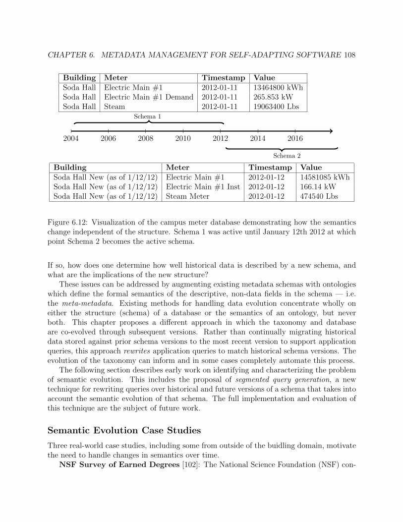
CHAPTER 6. METADATA MANAGEMENT FOR SELF-ADAPTING SOFTWARE 108
2004 2006 2008 2010 2012 2014 2016
Schema 1
Schema 2
Building Meter Timestamp ValueSoda Hall Electric Main #1 2012-01-11 13464800 kWhSoda Hall Electric Main #1 Demand 2012-01-11 265.853 kWSoda Hall Steam 2012-01-11 19063400 Lbs
Building Meter Timestamp ValueSoda Hall New (as of 1/12/12) Electric Main #1 2012-01-12 14581085 kWhSoda Hall New (as of 1/12/12) Electric Main #1 Inst 2012-01-12 166.14 kWSoda Hall New (as of 1/12/12) Steam Meter 2012-01-12 474540 Lbs
Figure 6.12: Visualization of the campus meter database demonstrating how the semanticschange independent of the structure. Schema 1 was active until January 12th 2012 at whichpoint Schema 2 becomes the active schema.
If so, how does one determine how well historical data is described by a new schema, andwhat are the implications of the new structure?
These issues can be addressed by augmenting existing metadata schemas with ontologieswhich define the formal semantics of the descriptive, non-data fields in the schema — i.e.the meta-metadata. Existing methods for handling data evolution concentrate wholly oneither the structure (schema) of a database or the semantics of an ontology, but neverboth. This chapter proposes a different approach in which the taxonomy and databaseare co-evolved through subsequent versions. Rather than continually migrating historicaldata stored against prior schema versions to the most recent version to support applicationqueries, this approach rewrites application queries to match historical schema versions. Theevolution of the taxonomy can inform and in some cases completely automate this process.
The following section describes early work on identifying and characterizing the problemof semantic evolution. This includes the proposal of segmented query generation, a newtechnique for rewriting queries over historical and future versions of a schema that takes intoaccount the semantic evolution of that schema. The full implementation and evaluation ofthis technique are the subject of future work.
Semantic Evolution Case Studies
Three real-world case studies, including some from outside of the buidling domain, motivatethe need to handle changes in semantics over time.
NSF Survey of Earned Degrees [102]: The National Science Foundation (NSF) con-

CHAPTER 6. METADATA MANAGEMENT FOR SELF-ADAPTING SOFTWARE 109
ducts an annual census of all research doctoral degrees received from accredited U.S. in-stitutions. The degrees are classified according to a taxonomy developed by the NSF; thisprovides the basis for aggregate statistics such as the number of Computer Science degreesearned in a given year. The degree classification taxonomy has changed over the course ofthe survey, which began in 1957, to reflect the evolution of degree programs (Figure 6.13).
Because degree programs do not evolve in “lock-step” with one another, the emergenceand refinement of newer degree areas such as Computer Science are not immediately reflectedin the taxonomy or the survey results. Furthermore, the process of retroactively applyingnewer classifications to historical data is largely manual and thus slow.
Campus Meter Database: The UC Berkeley campus contracts with an externalprovider for collecting and storing meter data tracking energy, power, steam and waterconsumption over time. The stored data is organized into a collection of tables — one foreach building — containing timeseries data for each measurement capability of a meter (re-ferred to as a field). The set of fields for each building is different: the field names providesome context for what the meter measures and how it relates to the building. The specificquantity being measured is left implicit.
Over time, meters have been replaced, resulting in different names for meter fields, orrecalibrated, resulting in a different distribution of data. These changes are reflected in thedatabase as new tables — for example, the table “Soda Hall” becomes “Soda Hall new (asof 1/12/12)” — which raises challenges for historical analyses (Figure 6.12).
Brick Ontology: As the Brick ontology evolves to introduce more classes or to refinethe definitions of existing classes, existing databases that depend on older versions of Brickmust decide how to adapt. This involves properly translating queries to take advantage ofnew classes or to reinterpret older classes.
Formalism and Preliminaries
This section formalizes the semantic evolution question for relational databases.
Definition 6.4.1. Relational Schema. A relational schema R is a set of attributes a1, . . . , an.Each attribute ai has a name given by name(ai). The range of values for an attribute ai inrelation Rj is given by Ai
j. The number of attributes in a relational schema Ri is given by|Ri|.
Definition 6.4.2. Database Instance. A database instance Di is a set of n tuples {d1, . . . , dn}where each tuple matches a relational schema Ri (written as Di ∈ Ri). This means thateach tuple d ∈ Di obeys |d| = |Ri| (has the same number of attributes) and dj ∈ Aj
i (the jthattribute in tuple d has a value within the permissible range given by Aj
i ).
The subscripts on relational schemas Ri and database instances Dj are logical timestampswhich increase whenever a new relational schema is introduced. A logical timestamp tcorresponds to a physical segment (extent) of time that may or may not be explicitly modeledin the schema. This notation allows the expression of sequences of schemas over time, e.g.

CHAPTER 6. METADATA MANAGEMENT FOR SELF-ADAPTING SOFTWARE 110
[Ri, . . . , Rk]. All logical timestamps in a sequence are unique and are ordered from smallest(least recent) to largest (most recent).
Definition 6.4.3. Metadata. In the context of relational databases, metadata properties arethe set of attributes in a relational schema that provide context or define properties of somedata. The semantics, or meaning, of each attribute determines what is metadata and whatis data.
In the campus meter database example (Figure 6.12), the data is the combination of atimestamp and a value. The table contains metadata in the form of which meter originatedthe data and which building the meter is associated with.
To simplify the discussion, full temporal segmentation is assumed: a database instanceDi is assumed to contain only records for the temporal extent corresponding to its logicaltimestamp, and that records for that temporal extent are only contained within databaseinstance Di.
The key treatment of each relational schema is to consider each discrete value of anattribute’s domain Ai
j as an OWL-style class. For example, each value in the Meter columnof the schemas in Figure 6.12 can be considered a label of an independent class. Formally,each value v in the domain of attribute Ai at schema version j is a new class Ci
jv. Thisenables a semantic evolution process to reason about the relationship between classes withina version using a taxonomy, and between versions using a semantic evolution operator2.
There are three semantic evolution operators:same, merge and split. Together, thesecharacterize most kinds of semantic evolutions. For any pair of classes Ci and Cj for twoschema versions i and j:
• same(Ci, Cj) indicates that the semantics of a class are unchanged between the twoversions
• merge(C1i , C2
i , Cj) indicates that the content of class Cj is defined by the union of two(or more) classes from the previous schema version (C1
i , C2i ).
• split(Ci, C1j , C2
j ) indicates that the content of class Ci at a prior schema version hasbeen split into two (or more) new classes in the later schema version (C1
j , C2j ).
A process rewriting schema i queries to execute on schema j can use these operators toinform the automated transformation of those queries. same operators do not change thequery (except to handle renamed fields). split operators result in a query which expressesthe union of the queries generated by substituting Ci with each of the new Ck
j classes that itwas split into. This can be handled automatically. merge operators require a disaggregationfunction to tell the rewritten query “how much” of the new class Cj matches the originalclass C1
i .
2For simplicity, a taxonomy (tree-base class organization) is used instead of a full ontology which candescribe a DAG class organization.

CHAPTER 6. METADATA MANAGEMENT FOR SELF-ADAPTING SOFTWARE 111
Taxonomy Evolution TypeEngineering2004 ⊆ Engineering2010 SameEcon2004 ⊆ Econ2010 SamePsych2004 ⊆ Psych2010 SameMath/CS2004 ⊆ CS/Info Sci2010 ∪Math2010 SplitOther2004 ⊆ Anthro2010 ∪Other2010 SplitPsych2004 ∪ Social Sci2004 ⊆ Social Sci2010 Merge
Table 6.2: A subset of the split/merge/same relationships between the 2004 and 2010 versionsof the NSF degree taxonomy in Figure 6.13
Figure 6.13 illustrates a subset of two versions of the NSF degree classification taxonomy,one from 2004 and another from 2010. Table 6.2 contains a few of the binary relationshipsbetween classes across the two versions of the taxonomy.
The set of Engineering degrees recognized by NSF did not change between the two ver-sions, and thus the relationship is same. The Mathematics and Computer Sciences (Math-/CS) category from 2004 was split into two separate categories in the 2010 taxonomy. Sim-ilarly, the Other category under Social Sciences was split to pull Anthropology degrees out.
There is an interesting merge between the two versions: the Psychology category is incor-porated under the Social Science category in 2010 despite these being separate in 2004. The2004 Psychology category is also involved in a same relationship with the 2010 Psychologycategory because they semantically refer to the same concept.
These three types may be broken down into expressions of relational operators that morespecifically describe the nature of the relationship between two versions of a taxonomy.Nonetheless the three types are enough to inform query generation for a wide family ofsemantic evolutions.
Segmented Query Generation
Segmented Query Generation (SQG) is a proposed technique for transparently executingqueries over a historical sequence of evolving relational schemas. This is one step of alarger, more complex process and is complementary to classic data cleaning and integrationtechniques. SQG operates by generating a new query for each historical schema version. Thisallows an application to transparently query multiple database versions as if they were undera unified schema. SQG accomplishes this without support from the underlying databasewhile reducing the effort required of a database administrator or application developer.
SQG takes advantage of semantic operators describing relationships between taxonomiesto transitively and automatically apply SQG across multiple versions of the database. Theexistence of monotonic relationships (same and split) between subsequent versions of ataxonomy allows the segmented query generation process to make safe assumptions about
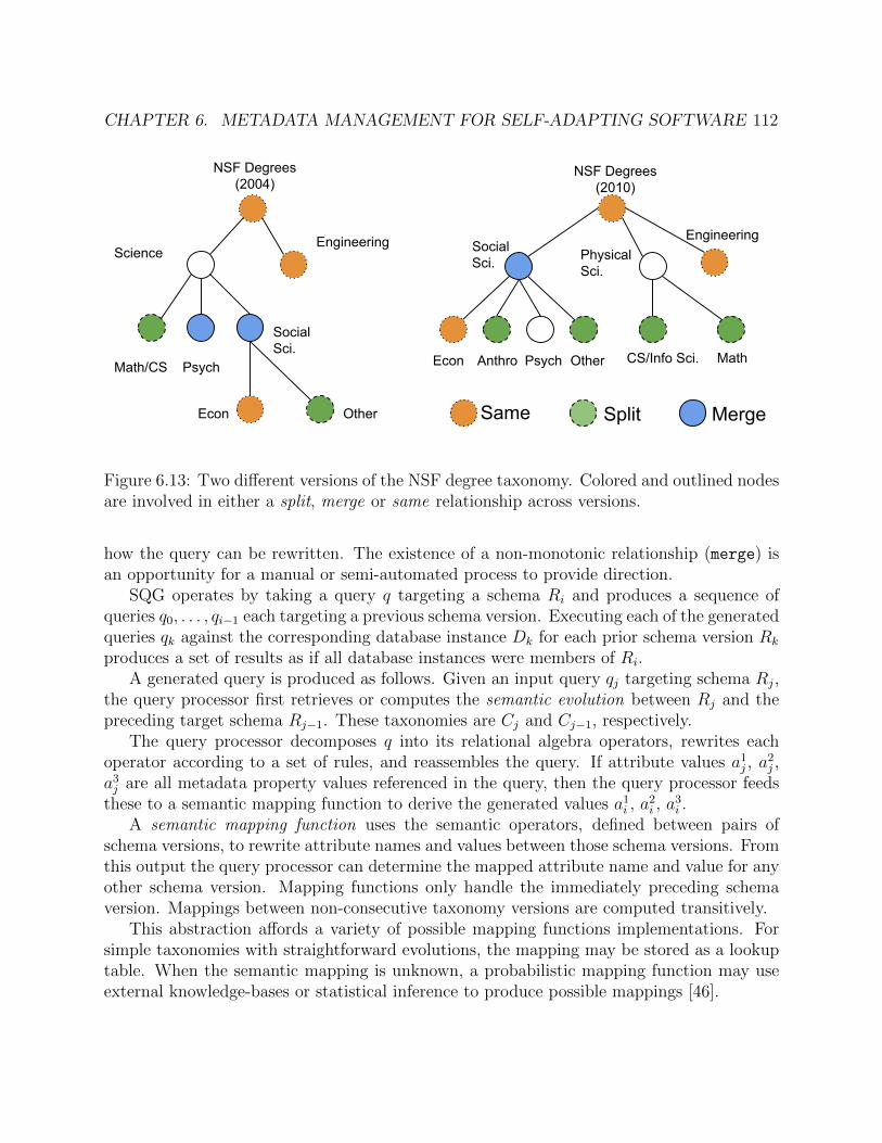
CHAPTER 6. METADATA MANAGEMENT FOR SELF-ADAPTING SOFTWARE 112
NSF Degrees (2010)
Social Sci. Physical
Sci.
Engineering
Econ Anthro Psych Other CS/Info Sci. Math
NSF Degrees (2004)
ScienceEngineering
Math/CS Psych
Social Sci.
Econ Other MergeSplitSame
Figure 6.13: Two different versions of the NSF degree taxonomy. Colored and outlined nodesare involved in either a split, merge or same relationship across versions.
how the query can be rewritten. The existence of a non-monotonic relationship (merge) isan opportunity for a manual or semi-automated process to provide direction.
SQG operates by taking a query q targeting a schema Ri and produces a sequence ofqueries q0, . . . , qi−1 each targeting a previous schema version. Executing each of the generatedqueries qk against the corresponding database instance Dk for each prior schema version Rk
produces a set of results as if all database instances were members of Ri.A generated query is produced as follows. Given an input query qj targeting schema Rj,
the query processor first retrieves or computes the semantic evolution between Rj and thepreceding target schema Rj−1. These taxonomies are Cj and Cj−1, respectively.
The query processor decomposes q into its relational algebra operators, rewrites eachoperator according to a set of rules, and reassembles the query. If attribute values a1
j , a2j ,
a3j are all metadata property values referenced in the query, then the query processor feeds
these to a semantic mapping function to derive the generated values a1i , a
2i , a
3i .
A semantic mapping function uses the semantic operators, defined between pairs ofschema versions, to rewrite attribute names and values between those schema versions. Fromthis output the query processor can determine the mapped attribute name and value for anyother schema version. Mapping functions only handle the immediately preceding schemaversion. Mappings between non-consecutive taxonomy versions are computed transitively.
This abstraction affords a variety of possible mapping functions implementations. Forsimple taxonomies with straightforward evolutions, the mapping may be stored as a lookuptable. When the semantic mapping is unknown, a probabilistic mapping function may useexternal knowledge-bases or statistical inference to produce possible mappings [46].
CHAPTER 6. METADATA MANAGEMENT FOR SELF-ADAPTING SOFTWARE 113
Discussion
Any solution for addressing the issue of semantic evolution should fulfill the following fourproperties:
• Correct: the mechanism should be correct and produce valid schemas that preservethe semantics of the mapping
• Transparent: the mechanism (e.g. schema mappings and semantic mappings) shouldnot affect how the query is expressed or executed
• Efficient: the mechanism should impose minimal overhead in terms of resource con-sumption at query time
• Automatic: the mechanism should minimize the human/manual effort involved
Work on SQG is still underway, but demonstrates promise in being able to handle thekinds of scenarios described above. SQG has the ability to be automatic, transparent andefficient because it produces queries which execute on the same optimized relational queryprocessors as the original query, with little or no human input. The correctness of SQGhas yet to be determined for all cases. The semantic evolution operators cover a varietyof semantic evolutions, but it is not known how general they are. Regardless, the need tohandle semantic evolution of schemas is an important issue with real-world applications, andshould be further researched.

114
Chapter 7
Platform Design and Implementationfor Self-Adapting Software
The final challenge in realizing a vision of self-adapting software is how to manage seman-tic metadata, at scale, on behalf of applications. Managing semantic metadata requires aplatform that can store, update and serve semantic metadata as well as enabling access tothe historical telemetry via the metadata. Linked data technologies — especially the for-mal axioms and rules defined in OWL and SHACL — place requirements on the metadatamanagement platform that are not well-served by existing systems. In particular, the use ofboth linked data models and timeseries data
This chapter outlines the requirements of semantic metadata management and detailswhy these properties are difficult to achieve at scale, in the context of existing data andmetadata platforms. Then, the chapter presents two complementary platforms which facili-tate self-adapting software at scale. The first, reasonable, provides a performant abstractionfor ontology management that simplifies the use of semantic web technologies for platformdevelopers. The reasonable software library enables new modes of interaction betweenlinked data and other data models. Second, the chapter develops the implementation ofthe Mortar platform, which implements the hybrid linked-data/timeseries access required byself-adapting software programming models (Chapter 5).
7.1 Scaling Metadata Management
The question of how to store and access metadata at large scale has become increasinglyimportant for big data and data warehouses [76]. Metadata in these settings describes thesource and provenance of the data in the warehouse, including the transformations andtreatments of that data. Many of the metadata management platforms developed to meetthe needs of large data warehouses leverage a graph-based data model [70]. However, theseplatforms do not treat the context of the data as a first-class object: these kinds of semanticdetails are to be included in the data being described and are not handled by the platform.
CHAPTER 7. PLATFORM DESIGN AND IMPLEMENTATION FORSELF-ADAPTING SOFTWARE 115
This section explores how metadata is managed in existing platforms designed for cyber-physical and IoT settings. In these settings, the content of metadata critically influences howapplications are written and how they find their data. This is especially true for self-adaptingsoftware.
Cyberphysical Data Platforms
A number of specialized databases have been developed for cyberphysical and IoT settings.These are predominantly characterized by the ability to ingest high rates of timeseries datafrom a large array of data sources such as sensors. IoT data is usually organized by attributesof the data source such as location or sensor type in addition to a unique identifier.
sMAP [39] is a protocol which uses a UUID as a primary key for each sensor channel thatreports to a data archiver. Each sMAP data source is described with key-value metadata.A number of metadata attributes are required and have well-known definitions, includingengineering units and the temporal resolution of the reported data. All other metadataattributes have arbitrary names, semantics and values. This design runs aground of mostof the same consistency and interpretability issues as Project Haystack. Other systemslike BuildingDepot 2.0 [147] and VOLTTRON [79] adopt similar key-value approaches tometadata: a small number of keys have well-defined semantics, but most attributes used byapplications are not standardized.
NoSQL databases are often used in IoT settings due to their flexible data models. Docu-ment stores can easily store complex metadata that can describe a data source, but the lackof first-class timeseries support means that NoSQL databases demonstrate poor storage andquery performance on large amounts of timeseries data [146]. Databases like IoTDB [146]and InfluxDB [101] adopt a slightly different data model. These store timestamped tuplesof key-value pairs and tags. String-valued keys act as attributes of the data source andnumerical-valued keys are treated as telemetry. The restricted data model enables more amore efficient and performant implementation. TimescaleDB takes this a step further by im-plementing specialized timeseries indices and storage in the Postgres RDBMS. These kindsof databases could provide access to telemetry on behalf of self-adapting software, but donot directly support the RDF data model and related technologies.
RDF Data Management
RDF databases typically focus on efficient storage of millions or billions of triples and pro-viding performant SPARQL queries over those triples. Research into how to improve thesedatabases has focused mostly on custom compression and run-length encoding schemes [105],bitmaps [90] or other specialized indices [67] and much less on Selinger-style [130] queryoptimization techniques for SPARQL execution. As a result, many SPARQL query proces-sors are designed for a single kind of workload: non-interactive but simple queries on verylarge knowledge bases. On this workload, modern SPARQL query processors use graphics

CHAPTER 7. PLATFORM DESIGN AND IMPLEMENTATION FORSELF-ADAPTING SOFTWARE 116
cards [138] or optimized relational query processors [55] to achieve execution times of secondsor minutes.
For self-adapting software, SPARQL queries are part of the “hot path” of code thatis conducting analytics or controls; even a simple application may run several SPARQLqueries in order to configure its own execution. [50] studied the performance of commonRDF databases on a Brick workload and observed that the storage optimizations made forlarge scale storage do not always translate to performant queries on smaller graphs. Thehighly-recursive queries characteristic of many Brick applications constitute a pathologicalworst-case for the index structures used for large RDF datasets. Thus, there is a need forSPARQL query processors that can “scale down” to provide good performance on smallerdatasets.
However, most RDF databases and SPARQL query processors do not support OWL orSHACL reasoning. Notable exceptions are Apache Jena [140], which supports reasoningthrough a plugin system, Protege [110] and TopBraid. The exact computation required toperform OWL or SHACL reasoning depends on the specific ontology language an ontologyis defined in, and which axioms or features it uses. Existing academic research has exploreddifferent ways of scaling reasoners for OWL (such as using Map Reduce [142]). However,much less work has focused on scaling SHACL reasoning (due to it being a more recentstandard) and the newer OWL ontology languages. Brick is defined in the OWL 2 RLprofile language [154], which has the advantage of being computable in polynomial time usingrule languages such as Datalog. Not all OWL 2 reasoners support the RL profile [58]. Anotable exception is RDFox [103], which implements an in-memory Datalog engine providingperformant SPARQL query processing and OWL 2 RL reasoning in the same package.
Most databases designed to support RDF do not provide support for versioned or tem-poral graphs. One reason for this deficiency is that the open-world assumption underlyingmany semantic web use cases is incompatible with the idea of a graph at a point in time.Temporal graph management must support inquiries of the form what is the content of thegraph at a given point in time; this requires knowledge of which elements of a graph existor are valid for a given temporal extent. However, under OWA the content of the graph isnot closed. This means that it is impossible to differentiate between whether a given fact isfalse at a given point in time in the graph, or if it is simply not included in the graph. Mostdatabases with support for versioning focus on dataset management, such as for scientificpublication. TerminusDB [113] supports a linked data graph model, but other systems likeDatahub [24], ProvDB [94], OrpheusDB [157] and DoltHub [43] support arbitrary struc-tured (usually relational) and unstructured datasets. These general solutions do not providesupport for RDF data management such as reasoning and graph queries.
Ontology-Based Data Access
Traditionally, RDF data management and timeseries data management techniques havelargely remained separate. Ontology-based data access (OBDA) [30, 156] demonstrateshow RDF-based metadata can contextualize the data stored in an external database. In
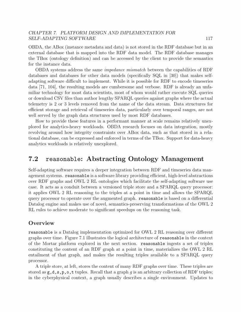
CHAPTER 7. PLATFORM DESIGN AND IMPLEMENTATION FORSELF-ADAPTING SOFTWARE 117
OBDA, the ABox (instance metadata and data) is not stored in the RDF database but in anexternal database that is mapped into the RDF data model. The RDF database managesthe TBox (ontology definition) and can be accessed by the client to provide the semanticsfor the instance data.
OBDA systems address the same impedance mismatch between the capabilities of RDFdatabases and databases for other data models (specifically SQL in [30]) that makes self-adapting software difficult to implement. While it is possible for RDF to encode timeseriesdata [71, 104], the resulting models are cumbersome and verbose. RDF is already an unfa-miliar technology for most data scientists, most of whom would rather execute SQL queriesor download CSV files than author lengthy SPARQL queries against graphs where the actualtelemetry is 2 or 3 levels removed from the name of the data stream. Data structures forefficient storage and retrieval of timeseries data, particularly over temporal ranges, are notwell served by the graph data structures used by most RDF databases.
How to provide these features in a performant manner at scale remains relatively unex-plored for analytics-heavy workloads. OBDA research focuses on data integration, mostlyrevolving around how integrity constraints over ABox data, such as that stored in a rela-tional database, can be expressed and enforced in terms of the TBox. Support for data-heavyanalytics workloads is relatively unexplored.
7.2 reasonable: Abstracting Ontology Management
Self-adapting software requires a deeper integration between RDF and timeseries data man-agement systems. reasonable is a software library providing efficient, high-level abstractionsover RDF graphs and OWL 2 RL ontologies which facilitate the self-adapting software usecase. It acts as a conduit between a versioned triple store and a SPARQL query processor:it applies OWL 2 RL reasoning to the triples at a point in time and allows the SPARQLquery processor to operate over the augmented graph. reasonable is based on a differentialDatalog engine and makes use of novel, semantics-preserving transformations of the OWL 2RL rules to achieve moderate to significant speedups on the reasoning task.
Overview
reasonable is a Datalog implementation optimized for OWL 2 RL reasoning over differentgraphs over time. Figure 7.1 illustrates the logical architecture of reasonable in the contextof the Mortar platform explored in the next section. reasonable ingests a set of triplesconstituting the content of an RDF graph at a point in time, materializes the OWL 2 RLentailment of that graph, and makes the resulting triples available to a SPARQL queryprocessor.
A triple store, at left, stores the content of many RDF graphs over time. These triples arestored as g,d,s,p,o,t tuples. Recall that a graph g is an arbitrary collection of RDF triples;in the cyberphysical context, a graph usually describes a single environment. Updates to

CHAPTER 7. PLATFORM DESIGN AND IMPLEMENTATION FORSELF-ADAPTING SOFTWARE 118
<g,d,s,p,o,t> <g,s,p,o>
Versioned Triple Store SPARQL Data Store
g: graph named: dataset identifiers,p,o: RDF triplet: valid interval start timestamp
reasonable
Index View Mgr
OWL 2 RL Datalog Dataflow
Figure 7.1: Logical architecture of reasonable and its interaction with other software com-ponents of Mortar
the graph come from datasets. A dataset d is a particular source of triples for a particulargraph at a particular point in time t; the content of the data source may change over time,but the identity does not. Examples of datasets would be the content of the Brick ontologyor the Brick model produced by the integration server described in Chapter 6. s, p and oare the components of an RDF triple in that dataset at that point in time.
During operation, for a given timestamp t and graph g, reasonable ingests the latesttriples for each dataset for that graph. This represents a snapshot of the content of thegraph at that time. reasonable then computes the OWL 2 RL entailment of the graph bypushing the triples through the dataflow graph. The resulting triples are then exposed to aSPARQL query processor.
Computing OWL 2 RL Entailment
Recall from Chapter 2 that OWL 2 RL is an ontology language that can be computed with arule engine. Prior work has established that Datalog is sufficient to compute these rules [141,103]. [100] lists the standard axiomitization of OWL 2 RL as a set of Datalog rules (see [2]for a detailed explanation of Datalog and its properties). A Datalog rule can be written asa Horn clause with a body — intuitively, the conditions that must be true for the rule to“fire” — and a head — the output of the rule. In [100] each of the Datalog rules is writtenwith respect to a single relation T(s,p,o) which contains all of the RDF triples in a graph.
The OWL 2 RL rules define which triples can be added to the graph that are impliedby the statements contained within the graph. An OWL ontology is an RDF graph whichinstantiates the rules to model the semantics of some domain. To compute the entailment ofa graph the ontology definition must be loaded into that graph. In reasonable, the Brickontology definition will often be included as a separate dataset as the description of thecyberphysical environment. These two datasets are unioned together when the triples areingested into reasonable.
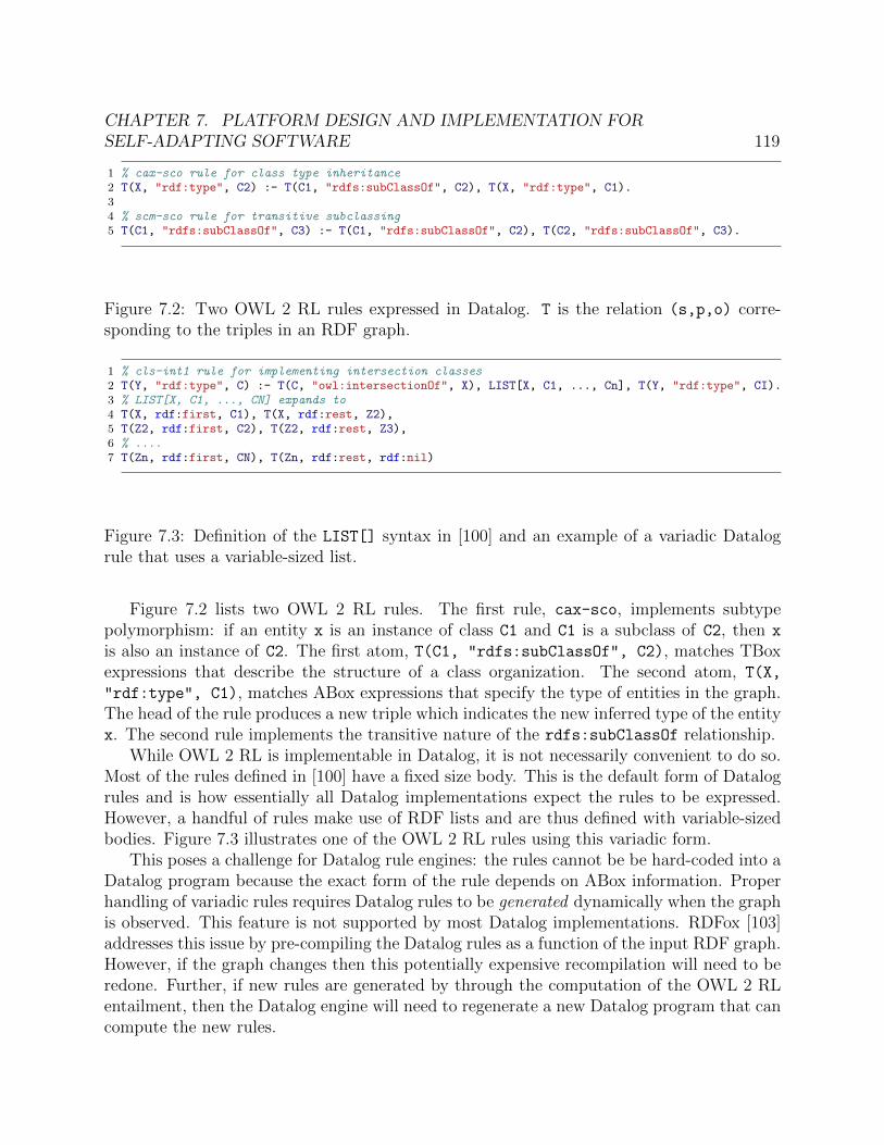
CHAPTER 7. PLATFORM DESIGN AND IMPLEMENTATION FORSELF-ADAPTING SOFTWARE 119
1 % cax-sco rule for class type inheritance2 T(X, "rdf:type", C2) :- T(C1, "rdfs:subClassOf", C2), T(X, "rdf:type", C1).34 % scm-sco rule for transitive subclassing5 T(C1, "rdfs:subClassOf", C3) :- T(C1, "rdfs:subClassOf", C2), T(C2, "rdfs:subClassOf", C3).
Figure 7.2: Two OWL 2 RL rules expressed in Datalog. T is the relation (s,p,o) corre-sponding to the triples in an RDF graph.
1 % cls-int1 rule for implementing intersection classes2 T(Y, "rdf:type", C) :- T(C, "owl:intersectionOf", X), LIST[X, C1, ..., Cn], T(Y, "rdf:type", CI).3 % LIST[X, C1, ..., CN] expands to4 T(X, rdf:first, C1), T(X, rdf:rest, Z2),5 T(Z2, rdf:first, C2), T(Z2, rdf:rest, Z3),6 % ....7 T(Zn, rdf:first, CN), T(Zn, rdf:rest, rdf:nil)
Figure 7.3: Definition of the LIST[] syntax in [100] and an example of a variadic Datalogrule that uses a variable-sized list.
Figure 7.2 lists two OWL 2 RL rules. The first rule, cax-sco, implements subtypepolymorphism: if an entity x is an instance of class C1 and C1 is a subclass of C2, then x
is also an instance of C2. The first atom, T(C1, "rdfs:subClassOf", C2), matches TBoxexpressions that describe the structure of a class organization. The second atom, T(X,
"rdf:type", C1), matches ABox expressions that specify the type of entities in the graph.The head of the rule produces a new triple which indicates the new inferred type of the entityx. The second rule implements the transitive nature of the rdfs:subClassOf relationship.
While OWL 2 RL is implementable in Datalog, it is not necessarily convenient to do so.Most of the rules defined in [100] have a fixed size body. This is the default form of Datalogrules and is how essentially all Datalog implementations expect the rules to be expressed.However, a handful of rules make use of RDF lists and are thus defined with variable-sizedbodies. Figure 7.3 illustrates one of the OWL 2 RL rules using this variadic form.
This poses a challenge for Datalog rule engines: the rules cannot be be hard-coded into aDatalog program because the exact form of the rule depends on ABox information. Properhandling of variadic rules requires Datalog rules to be generated dynamically when the graphis observed. This feature is not supported by most Datalog implementations. RDFox [103]addresses this issue by pre-compiling the Datalog rules as a function of the input RDF graph.However, if the graph changes then this potentially expensive recompilation will need to beredone. Further, if new rules are generated by through the computation of the OWL 2 RLentailment, then the Datalog engine will need to regenerate a new Datalog program that cancompute the new rules.

CHAPTER 7. PLATFORM DESIGN AND IMPLEMENTATION FORSELF-ADAPTING SOFTWARE 120
To be effective, reasonable must be able to nimbly switch between ontology versionswhich may contain different instantiations of variadic rules. reasonable addresses the vari-adic rule problem through a novel rule rewriting technique for OWL 2 RL rules. The rewrit-ten rules can be computed monotonically and preserve the semantics of the rules but arenot expressed in Datalog. Moreover, implementing the rewritten rules reduces the numberof joins that need to be performed during execution, which improves performance.
Semantics-Preserving Rewriting for Variadic Rules
The goal of the rewriting technique is to not require an external recompilation of the Datalogprogram when new instantiations of variadic rules become available in the graph. These rulesare much larger than most OWL 2 RL rules and can require many joins; for example, thecls-int1 (Figure 7.3) rule has a body of size 2N + 3 where N is the number of classesin the intersection condition. By avoiding recompilation, which typically involves throwingaway program state and restarting the process, a Datalog engine can maintain partiallymaterialized rule evaluations that accelerate future computation.
There are two challenges to variadic rule evaluation that must be addressed. First,because the instances of the variadic rules are derived from an unordered set of triples,the rewritten rule must be able to create the lists of conditions (LIST[X, C1, ..., CN] inFigure 7.3) in an efficient manner. Secondly, the rewritten rules must be able to determinewhen all of the conditions contained in the list are correct. The rewritten rules are notexpressed in Datalog; instead, they take the form of a small piece of monotonic logic that canbe computed as part of a fixed-point Datalog computation scheme. The logic is executed onevery iteration of Datalog computation and makes use of several monotonic data structures.
To address the first challenge, the rule rewriting technique makes the observation that theuse of RDF lists is intended to make the list a closed collection; that is, no other statementscan be spliced into the list or appended to the beginning or end of the list. This is truebecause the head of the list is known (the list is identified by the beginning entity x) and theend of the list is fixed (rdf:nil). However, the inherent order of the list does not actuallyfactor into the semantics of the rule. Specifically, changing the order of the elements in thelist (C1 through CN in Figure 7.3) does not change the output of the rule; this is true for allvariadic rules in OWL 2 RL. This observation means that the contents of the RDF lists canbe captured with a set rather than a linked list, as they are normally represented in RDF.This also means that the content of all RDF lists in a graph can be determined in a singlelinear pass over all of the triples by using a disjoint-sets data structure.
This construction works as follows. Recall that the disjoint-set data structure supportsthree operations. Add(x) adds an element x to its own set. Find(x) returns the set contain-ing x. Union(x,y) merges the set containing x with the set containing y into a single set.The list discovery algorithm requires a single disjoint-sets data structure D. During a passover all of the RDF triples in a graph, any triple with a predicate of rdf:rest has both itssubject and object added to D and then unioned. The object of a rdf:rest triple acts asa pointer to the subject of the next rdf:rest triple describing the structure of the list. By

CHAPTER 7. PLATFORM DESIGN AND IMPLEMENTATION FORSELF-ADAPTING SOFTWARE 121
1 % original cax-sco rule for class type inheritance2 T(X, "rdf:type", C2) :- T(C1, "rdfs:subClassOf", C2), T(X, "rdf:type", C1).3 % rewritten cax-sco rule4 PSO(P, S, O) :- T(S, P, O). % predicate-indexed relation5 Instances(X, C) :- PSO("rdf:type", X, C). % entity-indexed type relation6 Subclasses(C1, C2) :- PSO("rdfs:subClassOf", C1, C2). % class-indexed subclass relation7 T(X, "rdf:type", C2) :- Subclasses(C1, C2), Instances(X, C1).
Figure 7.4: The cax-sco rule implemented to take advantage of intermediate relations
unioning the heads and tails of the list segments, the sets in D will converge to the contentsof all the lists defined in the RDF graph. The order of the values of the lists is not preserved,but this is not required for correctness.
Once the content of the lists are known — after one pass over the input triples — therewritten rule uses a Map<URI, Bitset> named conditions to determine when all of therule conditions in each list are met for each URI. The map has an entry for each URI in thedataset; the value of the map is a bitset of size N where each position i ∈ 1, ..., N is 1 ifthe condition Ci in the list is true for that URI and 0 otherwise. On each iteration of theDatalog engine, the rewritten rule checks each of the conditions for each URI and updatesthe bitset accordingly. If all of the elements of the bitset are set and the other conditions ofthe rule are met, then the rule fires. One disjoint-sets data structure is used to capture allRDF lists in a graph. A unique conditions map is created for each variadic rule.
Redundant checks can be mitigated with two optimizations. First, the rewritten rulechecks the other atoms of the body before updating the bitset. This avoids performing thechecks on URIs that will never meet the other conditions of the rule. Secondly, the rulechecks the value of the bitset before evaluating all of the conditions to avoid recheckingURIs that have already caused the rule to fire.
Implementation
reasonable is built on DataFrog [93], a simple, embeddable Rust-based Datalog engine.Because of the embeddable nature of the engine, there is no provided runtime. The hostprogram has to build and repeatedly evaluate the rules until no additional tuples are pro-duced. This constitutes a fixed-point evaluation scheme.
The formalization in [100] only uses a single relation T(s,p,o) In a fixed point iterationevaluation scheme, any new tuples produced by a relation will propagate to all dependentrelations. A rule is dependent on rule relation if its body contains an atom that is the headof another rule. Each time a new tuple is generated by a rule, all dependent rules must berun that iteration. The iterations stop when no new tuples are generated. Because of thesedynamics, the use of a single relation, T(s,p,o), to implement all OWL 2 RL rules makesall rules dependent on one another. This means that if any rule generates a new tuple, all
CHAPTER 7. PLATFORM DESIGN AND IMPLEMENTATION FORSELF-ADAPTING SOFTWARE 122
“downstream” rules must be reevaluated, even if that rule would otherwise not fire.To avoid this issue, reasonable redefines the OWL 2 RL rules to make use of intermedi-
ate relations. This reduces the total number of iterations by removing dependencies betweenunrelated rules. Consider the cax-sco rule as written in Figure 7.4 as an example. As writ-ten, the rule would need to be reexecuted each time the T relation changed. Figure 7.4 showsthe implementation of cax-sco that reasonable uses. The implementation makes use of 3intermediate relations: PSO(P,S,O) is a predicate-indexed relation of the tuples in the RDFgraph; Instances(X,C) is an entity-indexed relation of the types c of each entity x in thegraph; Subclasses(C1,C2) is a class-indexed relation of the subclass relationships. Theserelations do not typically change after the first couple of iterations of Datalog evaluation.
reasonable is implemented as a Rust library in order to embed Datafrog and to facili-tate embedding in other programs. The Datafrog engine was chosen because it was simpleto extend with monotonic, albeit non-Datalog, logic such as the rule rewriting technique de-scribed above. The reasonable implementation is 3182 lines of code. This does not includeDatafrog but does include the binding code to support a Python 3 package that provides ahigh-level interface to reasonable1.
Currently, reasonable can receive triples from Postgres and SQLite, using triggers toprompt the reevaluation of the OWL 2 RL rules when new data is inserted. reasonable doesnot implement any differential computation techniques to reduce redundant computationwhen triples are removed; instead, reasonable just reevaluates the entire Datalog program.reasonable can dump the output of the reasoning process into an in-memory or on-diskstore which can be accessed by a SPARQL query processor.
Benchmarks and Evaluation
The performance of reasonable is evaluated by measuring the execution time of reasonableperforming OWL 2 RL inference on a collection of RDF graphs. The RDF graphs are sourcedfrom the Mortar dataset described in the next section; there are 109 graphs, ranging in sizefrom 40 triples to 17,500 triples. reasonable is compared against OWL-RL, a Pythonpackage adopting a naive approach to OWL 2 RL evaluation, and Allegrograph [55], acommercial triple store with an optimized reasoner.
The experimental setup is as follows. For each RDF graph in the dataset, a new graphis created that has the Brick v1.1 ontology and RDFS ontology definitions loaded into thegraph; this adds an additional 15,000 triples to each RDF graph. Each augmented graphis imported into a fresh instance of the reasoner — no state is preserved between runs —and the reasoner is triggered. A script measures the execution of the reasoning process asdistinct from the time it takes to load the triples into each reasoner. OWL-RL is executedin-memory; Allegrograph is executed from a Docker container. Each RDF graph is reasoned10 times.
1https://pypi.org/project/reasonable/

CHAPTER 7. PLATFORM DESIGN AND IMPLEMENTATION FORSELF-ADAPTING SOFTWARE 123
Figure 7.5: Comparing performance of reasonable with OWLRL and Allegro over morethan 100 Brick models.
The results are summarized in Figure 7.5. On average, reasonable is 7x faster thanAllegrograph and 41x faster than OWL-RL. If the reasoning duration is normalized to the sizeof the input graph (before loading in the Brick and RDFS ontology definitions), reasonableis 9x faster than Allegro and 48x faster than OWL-RL.
The improved performance of reasonable over available alternatives enables a reasonerto adopt a new role as a timely transformation of data that can be incorporated into ananalytics workflow rather than an offline batch processing phase. In practice, waiting halfa minute or longer for a reasoning step to complete severely impedes exploration and oftenrequires the user to manually manage cached versions of the reasoned graph to avoid incurringthe expensive computation.
7.3 Mortar: A Platform for Reproducible Building
Science
Mortar — deployed at https://beta.mortardata.org — is a data platform which enablesthe execution and evaluation of self-adapting analytics applications over a large number ofmetadata-enriched buildings. This section describes the Mortar dataset and the architectureand implementation of the data platform that serves that data in a manner supportingself-adapting applications.

CHAPTER 7. PLATFORM DESIGN AND IMPLEMENTATION FORSELF-ADAPTING SOFTWARE 124
Figure 7.6: Histogram of number of data streams for all sites (µ =241).
Temperature Sensor 7380 Luminance Sensor 257Occupancy Sensor 445 Pressure Sensor 148
Outside Air Temp. Sensor 362 Cloud Cover 32Setpoints (generic) 2331 Power Meters 77
VAVs 4724 AHUs 467HVAC Zones 4887 Dampers 1662
Non BMS Thermostats 123
Table 7.1: Count of streams and equipment available in the testbed data set, aggregated bytype. AHU and VAV totals include related equipment such as fans and pumps.
Public Dataset
Mortar contains timeseries and metadata for over 100 buildings, constituting over 9 billiondatapoints and 750 million combined hours of telemetry. The majority of the data streamsin the platform adhere to a 15-minute interval (.001 Hz), though some are more fine-grained(up to 1 Hz).
Figure 7.6 describes the distribution of the number of streams per building. Each buildingis accompanied by a Brick model that describes the building, its equipment and subsystems,available points, and references to timeseries data streams. Table 7.1 enumerates some ofthe types of available points and equipment in the testbed.
The majority of the dataset is made up of large commercial buildings belonging to auniversity campus. The buildings are typically used as offices, classrooms, research facilitiesand health care clinics. The average building has a floor area of 70,000 sqft, 3 floors andmore than 100 rooms, while the largest building is a large library with a floor area above

CHAPTER 7. PLATFORM DESIGN AND IMPLEMENTATION FORSELF-ADAPTING SOFTWARE 125
SPARQL Query ProcessorTelemetry and Timeseries Data
bldg
1bl
dg2
bldg
3
Versioned Triple Store
t0 Brick.ttl
bldg1.ttl
<s,p,o>
...
<s,p,o>
...
Brick.ttl
bldg2.ttl
<s,p,o>
...
<s,p,o>
...
Brick.ttl
bldg3.ttl
<s,p,o>
...
<s,p,o>
...
bldg1
bldg1.ttl <s,p,o>
...
t0
t1
t0bldg2
t3
t1
t4
bldg3 OWL 2 RL Reasoner
bldg
1bl
dg2
bldg
3
API Frontend
Data Storage Metadata Inference and Query Processing
Figure 7.7: Mortar platform
400,000 sqft. Most buildings are conditioned using large built-up HVAC systems with airhandlers and local distribution boxes, controlled by building automation systems. Chilledwater and hot water are produced by a central plant and distributed through large pipes tomost buildings. Some additional chillers are installed in some buildings to complement thecentral system.
Other buildings in the data set come from a set of independent data collecting efforts.Most of the non-campus buildings are part of an ongoing project to develop a buildingoperating system; these are mostly small commercial buildings ranging from movie theatresto fire stations to animal shelters. Data collected includes sensors, setpoints and otherdata associated with thermostats, building meters, electric vehicle charging stations, HVACand lighting systems as well as general occupancy, temperature, illumination and humiditysensors.
Platform Architecture
Mortar — which originally stood for Modular Open Reproducibility Testbed for Analysisand Research — is a platform for storing contextualized timeseries data to support self-adapting analytics applications. Mortar supports the long-term storage of many timeseriesstreams and RDF graphs that describe and contextualize that data. The management andaccess of timeseries data and RDF metadata is provided through a declarative API frontenddesigned for high numbers of long, concurrent connections typical of clients downloadinglarge amounts of data. The API frontend supports the operations supported by self-adaptingsoftware (Chapter 5).
Figure 7.7 illustrates the architecture of the Mortar platform. The data storage com-ponent contains two logical databases: a timeseries database that organizes data by graphname (bldg1, bldg2, bldg3 in the figure) as well as stream name, and a triple store using the

CHAPTER 7. PLATFORM DESIGN AND IMPLEMENTATION FORSELF-ADAPTING SOFTWARE 126
g,d,s,p,o,t schema described in §7.2. The versioned nature of the triple store is illustratedin the figure: for bldg1, the triples corresponding to dataset Brick.ttl at t0 and the triplesfor dataset bldg1.ttl at t1 will constitute the latest version of the graph.
The reasoner wraps the reasonable library in a subscription to the versioned triple store.The reasoner maintains the materialization of the most recent version of each graph in thetriple store and makes this available to a SPARQL query processor. As new triples are addedto the triple store, the reasoner is able to update the materialized graph using a minimalamount of work; this facilitates bulk uploads. Historical versions of a graph are evaluatedon demand and cached.
Platform API
An API frontend exposes a set of operations to clients, documented in Table 7.2. These meth-ods interact with both the timeseries and RDF database (triple store). The register stream
method adds metadata to the RDF graph about a particular data stream, uniquely iden-tified by a 36-byte UUID. All data streams must exist within exactly one graph. Callingregister stream adds the data stream to that RDF graph; providing the extra argumentsallows Mortar to add additional triples such as rdfs:label for name, rdf:type for class
and brick:hasUnit for units. Any data stream that is registered without a class argu-ment will be asserted as an instance of brick:Point — the most generic kind of data source.The add * methods support streaming JSON POSTs as well as batch uploads from Turtlefiles (for metadata) and CSV files (for data).
qualify takes as an argument a list of SPARQL queries q0, . . . , qm and an optional listof graph names g0, . . . , gn and returns an m×n matrix T where each entry Tij is the numberof tuples returned by running query qi on graph gj: Tij = |qi(gj)|. This allows a client toquickly determine which graphs in Mortar contain the data and metadata necessary to runan application. If a list of graph names is provided, qualify only executes the queries onthose graphs, otherwise it executes on all stored graphs.
get metadata takes a SPARQL query as an argument and returns the results of thequery executed over the indicated graphs. Because of reasonable, the SPARQL queries arealways served over fully reasoned graphs.
get data takes a SPARQL query as an argument and returns the timeseries data andmetadata for all data streams described by that query. The start and end arguments boundthe temporal extent of the query, and agg and window describe any requested server-sideaggregation (e.g. aggregating each data stream to a 15-minute average). This requires theAPI frontend to determine which elements of the SPARQL query correspond to timeseriesdata. Nominally, any instance of brick:Point represents a source of data; however, not allof these will have data associated with them, and the name (URI) of the entity needs to beassociated with the timeseries UUID. A new Brick relationship, brick:timeseries, relatesa data source to the metadata about its storage. The subject of brick:timeseries is aBrick Point entity; the object is a complex object with several properties:

CHAPTER 7. PLATFORM DESIGN AND IMPLEMENTATION FORSELF-ADAPTING SOFTWARE 127
API Function Signature
Met
adat
a register stream(uuid, graph, name?, class?, units?)
add metadata(graph, dataset, [triple])
get metadata(query, [graph]?) -> table
qualify([query], [graph]?) -> table
Dat
a add data(uuid, [timestamp, value])
get data(query, start?, end?, agg?, window?, [graph]?) -> [table]
get data([uuid], start?, end?, agg?, window?) -> [table]
Table 7.2: API operations supported on the Mortar platform. A ? suffix indicates theparameter is optional. A [parameter] notation indicates the type is a list.
• brick:hasTimeseriesId: a literal-valued property that indicates the primary keyidentifier for the data stream (in Mortar this is a 36-byte UUID)
• brick:storedAt: an optional property that encodes the location of the database con-taining the data for the data stream. This allows distributed Brick models to alwaysretain a pointer to where related data is stored, and allows Brick points to distributetheir storage across multiple databases.
The brick:timeseries property is queried automatically by the API frontend when get data
is called to determine which data streams must be fetched.The return value of get data is a set of 3 tables. The first table, streams, contains the
names, UUIDs, units and enclosing graph names of each of the data streams returned bythe query. The second table, metadata, contains the results of the SPARQL query. The lasttable, data, contains the timeseries data indexed by timestamp and UUID.
Mortar supports basic access control at the level of graphs. API keys can be created thatgrant read and/or write access to the metadata and data for a particular graph. The resultsreturned by the Mortar API will have all inaccessible data streams and graphs elided.
Platform Implementation
The Mortar platform is implemented using a collection of existing open-source software andcustom-built software. The timeseries and versioned triple store in Figure 7.7 are built onPostgres. The timeseries storage uses TimescaleDB, a timeseries-optimized extension forPostgres. The reasoner is an HTTP server implemented in Rust that wraps reasonable. Ituses LISTEN/NOTIFY to subscribe to changes to the versioned triple store table and prop-agates those changes to the in-memory reasoner, and eventually to the SPARQL queryprocessor. The API frontend is implemented in Go and incorporates a simple throttle mech-anism to limit the number of concurrent connections; this helps limit the ability of a largenumber of clients to overwhelm the server.

CHAPTER 7. PLATFORM DESIGN AND IMPLEMENTATION FORSELF-ADAPTING SOFTWARE 128
These three services — the database, the reasoner and the API frontend — are all dis-tributed in Docker containers to facilitate deployment. These containers may be hosteddirectly on a host machine, using a tool like docker-compose to manually manage the de-ployment and scaling of the services, or using a cluster management system like Kubernetes.
Conclusion
This chapter has explored the platform requirements for self-adapting software. The richsemantic metadata supporting self-adapting software requires the use of a reasoner to mate-rialize the inferred elements of the graph. This enables greater flexibility in the queries madeby self-adapting software. The integration with a data platform requires the reasoner to betimely and efficient so that materialized RDF graphs can be part of interactive workflows.
reasonable is a new OWL 2 RL reasoner optimized to perform reasoning over changinggraphs and ontologies and to act as an efficient transformation step between a versionedtriple store and a SPARQL query processor. reasonable is implemented as a standalonelibrary and demonstrates performance 7-40x times faster than existing OWL 2 RL reasoners.
The Mortar data platform provides timeseries and RDF storage for large amounts ofdata, organized into graphs and described using Brick metadata. Mortar provides a simpleAPI that allows self-adapting software to discover and access the metadata and data neededto customize its operation. Mortar is available online at https://beta.mortardata.org.
129
Chapter 8
Adoption and Impact
Brick, Mortar and their related technologies detailed in this thesis are influencing data-driven practices, standards and research in academia, industry and government.
8.1 Metadata Standardization and Semantic
Interoperability
When Brick was released in 2016 there were few efforts that addressed the need for consistentand interpretable metadata for analytics and controls, and even fewer that were recognizedor adopted by the building industry. The dominant practice was for controls and BMSvendors to sell access to telemetry on a point-by-point basis through proprietary APIs andinterfaces. Companies like SkyFoundry, the company behind Project Haystack, helped toestablish that a distinct analytics platform with first-class support for analytics “apps” andhistorical telemetry could provide value to building owners and stakeholders. As a result,Project Haystack’s terminology and marketing characterized much of the building industry’sunderstanding of “semantic metadata” despite the fact that the underlying product andtechnology did not address the key data modeling challenges (Chapter 4). Publications,talks, interviews, blog posts and webinars about Brick evinced the shortcomings of informaltag-based metadata and provided an alternative that was built over existing W3C standards.Since 2016, Brick and its ideas have influenced a number of technologies, standards and otherontologies.
ASHRAE 223P
ASHRAE (American Society of Heating, Refrigeration and Air-Conditioning Engineers) is aprofessional organization behind many standards in the building industry, including BAC-net [14]. In 2012, ASHRAE established the Application Profile Working Group (AP-WG) todevelop standardized interfaces for interacting with common types of equipment [9]. Accord-

CHAPTER 8. ADOPTION AND IMPACT 130
ing to the working group website, the proposed standard would “provide a machine-readableway of representing the capabilities of individual BACnet devices such as services and ob-jects supported [6].” The intended output of the working group was to author annexes tothe BACnet standard that would encode this information in the networked representationof each device.
Several years into this effort, it was recognized that standardizing interfaces was only partof the problem: applications needed contextual information in order to find which interfacesof which equipment they needed to operate. In 2018, the goal of the working group wasamended to develop a new standard, 223P1, entitled Semantic Tags for Building Data. Thefocus was still on applications, but rather than specifying the interfaces to the devices in thebuilding, the group would
“investigate the development of semantic information concepts and vocabulariessuitable for building data of various application areas. This will extend the levelof semantic information to include application concepts.[7]”
This new direction was intended to incorporate aspects of both the Brick and ProjectHaystack metadata efforts [8]. At time of writing, a draft of 223P is expected to be re-leased in 2022.
223P will be expressed as a semantic web ontology built using OWL and SHACL. Thedesign is based on the SAREF4SYS ontology, but extends the generic SAREF4SYS conceptswith classes which are relevant to the building domain. The core concepts to 223P areSystems, Devices, Connections and Connection Points: this provides an abstract data modelwhich can express more detailed topology and system composition than either Brick orHaystack. Systems are a collection of connected devices or other systems. Devices aretangible objects designed for a specific task, such as a pump or variable frequency drive.Systems can be “connected” to other systems and devices can be “connected” to otherdevices. Devices may be composed of atomic Parts, but Parts do not have any connectionsto other Parts or other entities in the model. Unlike Brick, 223P Connections are objectsin the model; in Brick, connections are captured through the brick:feeds relationshipwhich is a simple RDF predicate. By making Connections objects, it is possible to attachadditional properties to them. Example of Connections in 223P include pipes, ducts andwires. Connections connect to devices and systems by means of Connection Points, whichare also objects and can also be described with additional properties such as the directionof some medium flowing through the connection.
The relationship between Brick and 223P is promising. The two ontologies differ in theirintended use cases and expected data sources. Brick is designed for “brownfield” settings, inwhich the ground truth of which entities and data sources are actually present in a buildingis not necessarily known or captured in a structured manager. As a result, Brick models aredesigned to be created from partial or incomplete information. Furthermore, by concentrat-ing on enabling data-driven applications, Brick eschews detailed “white-box” descriptionsof building subsystems: this detail is largely unnecessary, hard to come by, and difficult to
1The P suffix refers to the fact that the standard is considered proposed until it is ratified.
CHAPTER 8. ADOPTION AND IMPACT 131
maintain. In contrast, 223P is designed to be implemented during the commissioning stage ofa building. Parts of a 223P model could be packaged with the equipment and controllers thatare installed in the building. A systems integrator would stitch 223P-compliant metadatasnippets together into a detailed and complete representation of the building’s subsystems.
Brick and 223P are on track to be compatible. Several of 223P’s concepts are rooted inconcepts imported from Brick; at time of writing, the imported concepts include substances,equipment, points and locations. All elements of 223P’s data model can be simplified intoa form that Brick can express: the relationships between Systems and Devices can be ex-pressed as compositional and topological relationships in Brick; sources of timeseries dataand their properties may be represented in Brick directly. This means that Brick model willbe derivable from a 223P model, ensuring forward compatibility.
DOE Semantic Interoperability Project
The U.S. Department of Energy has identified the lack of semantic interoperability betweentechnologies as a fundamental barrier to achieving grid-interactive, energy efficient (GEB)buildings at scale. In [19], researchers from the National Institute of Standards and Tech-nologies (NIST) and several national labs and universities propose a 3-part pathway forenabling semantic interoperability.
The first component is working with industry and existing metadata representation ef-forts such as Brick and Haystack to address known shortcomings of these existing approaches.As established in [51] and this thesis, Haystack models suffer from significant customizationin the field which reduces consistency and interpretability between deployments. Brick ad-dresses these issues, but is built on semantic web technologies that are unfamiliar to manypractitioners. [19] proposes leveraging the existing overlap between Brick and Haystack todevelop a new standard, ASHRAE 223P, to unify industry and academic metadata efforts.
The second component is to design this new standard in such a way that it can be usedby building owners to identify and require interoperable components when procuring equip-ment, controllers and applications. The key idea is to use the standard not as a post-hocdescription of existing cyberphysical resources but as the mechanism through which inter-operable cyberphysical systems can be assembled. Products should be bought because theysupport this new standard, and the standard should provide a consistent way of describingthe capabilities and structure of the products. This will ultimately reduce commissioningand system integration costs.
The third component is the creation of standard tools to assist in the implementationof the standard and a testing framework which can verify compliance of products to thestandard. This is the approach taken by the BACnet standard [14]. According to [19], ittook BACnet more than two decades to achieve its current 64% market share: this wasgreatly accelerated by the existing of an independent testing group called BACnet TestingLaboratories. A similar approach is proposed for semantic metadata. The testing frameworkshould ensure that standard-compliant products are able to support an array of representa-tive real-world use-cases and applications.

CHAPTER 8. ADOPTION AND IMPACT 132
Work on this semantic interoperability vision began in 2020 and will accelerate overthe next few years. Software teams ant NREL have begun implementation of ontology-agnostic tools for constructing metadata models of buildings that can be “compiled” toeither Haystack or Brick. As part of this effort, a recent review [117] compares and contrastsa variety of metadata schemas and ontologies focusing on energy-oriented applications forbuildings.
Haystack v4
Project Haystack has been undertaking a redesign of the metadata model, addressing long-standing issues in the design that have been noted by the community and identified by thework in this thesis [121]. Among the changes is a shift to a Brick-inspired design. Rather thanrelying entirely on ad-hoc collections of tags for meaning, the new design defines well-knownsets of tags which have documented definitions:
“It has become clear over the last few months that there is no getting aroundcoining an identifier for every single point type.[123]”
This addresses some of the consistency issues incumbent in the existing Haystack design,but does not fully address structured extensibility or unclear subclass relationships — bothissues formalized in Chapter 4. Haystack 4 also provides an RDF-compatible export. Notethat this does not constitute the development of an ontology: the graph export is simplyan RDF representation of the existing Haystack data model. As as result, the inferencetechniques for extracting Brick metadata from a Haystack model — covered in Chapter 6— are still necessary.
Other Alignments and Ontologies
A number of other ontologies and metadata representations for buildings have been developedsince 2016. The Brick ontology has established formal alignments and translators with mostof these other representations.
Building Topology Ontology
The Building Topology Ontology (BOT), introduced in [126], is a simple upper ontologywhich defines core physical concepts of a building’s construction. Because the conceptsdefined in BOT are generic, it is possible to align it with other ontologies such as Brick andIFC [129]. BOT is being developed by the Linked Building Data community group throughthe W3C organization. Brick maintains a formal alignment with the BOT ontology, meaningthat BOT concepts can be derived from Brick models.
RealEstateCore
RealEstateCore (REC), introduced in [63], is a domain ontology developed to support data-oriented real estate applications. There is a high degree of overlap between the concepts

CHAPTER 8. ADOPTION AND IMPACT 133
defined in Brick and those defined in REC, and REC does cite Brick as an inspiration forits design of data sources and sinks. However, REC takes the extra steps of modeling theinterfaces to different building devices, as well as modeling organizations and individuals andother administrative structures and entities that interact with buildings. Brick maintains aformal bidirectional alignment with the REC ontology, meaning that REC and Brick modelscan be derived from each other.
Virtual Buildings Information System
The Virtual Buildings Information System [145] is a asset tagging and classification schemethat defines short, hierarchical 4-level names for common types of assets in buildings. VBIScovers equipment for a broad range of building subsystems including HVAC, water, security,lighting, fire suppression and kitchens. VBIS is designed to annotate existing records storedin other databases or files, so it does not define an API (other than requiring string matching).Because VBIS is distributed as a set of spreadsheets, it is not possible for Brick to definea formal mapping between the two metadata representations. Instead, Brick defines a newproperty for relating a VBIS tag to a Brick entity. The implementation uses SHACL shapesto define regular expressions which constrain the content of the VBIS tag to be appropriateto the Brick class. The implementation can also infer a Brick class for an entity with a givenVBIS tag.
Google’s Digital Buildings Ontology
Google has also been developing its own metadata model for real estate, equipment andequipment data which takes inspiration from Brick [20]. The ontology, named Digital Build-ings, is built on a custom configuration language and custom tooling which can producean OWL-based ontology as output. Part of the reason for a custom configuration languageand tooling is to circumvent some of the modeling issues which arise from the open-worldassumption that underlies OWL. Digital Buildings defines Protobuf messages and fields formany different kinds of equipment. In contrast to Brick, Digital Buildings equipment are de-fined by which inputs and outputs they represent; for example, a VAV with Reheat conceptin Digital Buildings would require that the model includes points about a reheat valve inaddition to the points for the VAV. The Digital Buildings effort is open-source and maintainscompatibility with Brick and Haystack as a long-term goal [59].
8.2 Open Data Research Efforts
While Mortar is not the first open-data research platform for buildings and other cyberphys-ical data, the use of an expressive ontology to describe the hosted data has inspired andcomplemented several other open data research efforts.

CHAPTER 8. ADOPTION AND IMPACT 134
Figure 8.1: Technologies for design, operation, analytics, controls and modeling of buildingsare siloed and rarely interoperable
Skewering the Silos
In 2019, DOE accepted a grant proposal for the further development of Brick as a “lin-gua franca” unifying the silos of technologies used across different data-oriented processes(Figure 8.1). As part of executing the grant, the Mortar platform would be extended andfurther developed into a production-ready analytics platform containing reference implemen-tations of many common analytics and controls applications. Collaborations with industryand academic partners have resulted in a large array of datasets being donated to the re-search team. These datasets will be cleaned, anonymized and hosted on a publicly-accessibleMortar instance.
The grant work also involves developing connectors or translators between Brick andother building technologies, including Modelica [150], CDL [149], Haystack [118], gbXML [60]and BuildingSync [88]. The work in this thesis advances the grant work in an open-sourcemanner, and establishes a common platform for continuing that kind of research.

CHAPTER 8. ADOPTION AND IMPACT 135
Annex 81: Data-Driven Smart Buildings
Annex 81 is an International Energy Agency project bringing together international expertsin data, metadata, ontologies and buildings to establish best-practices [77]. The project isdivided into multiple sub-tasks, each of which focuses on a different component of data-drivenbuildings. Two sub-tasks are directly relevant to the work in this thesis. The “Open Dataand Data Platform” subtask will review and report on standards, protocols and proceduresfor capturing data about a variety of building systems and making that data available forresearch and applications. This will involve grappling with questions of data governance,security and privacy in addition to the mechanical issues of how to manage that data. The“Applications and Services” subtask will explore the range of applications and use-cases thatare enabled through access to high-quality and ubiquitous data about buildings. At timeof writing, Brick and Mortar have already been presented to the group and are helping toframe the scope of the project over the next 5 years.
CSIRO Data Clearing House
The Commonwealth Scientific and Industrial Research Organisation (CSIRO) in Australiais undertaking the development of a Smart Building Data Clearing House (referred to as theDCH), a single location for building data at a national scale [3]. The platform will supportsecure, differentiated access to thousands of buildings across many different sectors of theeconomy and support data-driven applications providing audits, energy efficiency measures,fault detection and other features. Brick is a key technology to the development of theDCH. Like in Mortar, each building in the DCH will be described with a Brick model whichrepresents the structure of the building and its subsystems and the context of the availabledata sources. The adoption of Brick in the DCH creates an opportunity for external andindependent development efforts to address some of the open usability issues around Brick,such as effective query languages and graph management.
8.3 Brick Consortium
Representatives of UC Berkeley, UC San Diego, Carnegie Mellon University, Johnson Con-trols Inc. and IBM came together to form an open industrial consortium for the continueddevelopment, support and research of Brick [33]. The consortium will publish a Brick Spec-ification that details how products and buildings can become compliant with Brick. Thiswill help evolve Brick to a de-facto standard, a stance reinforced by its deep integrationwith the emerging ASHRAE 223P standard. The consortium is implemented as a non-profitcorporation with carefully designed disclosure bylaws that ensure that the Brick specificationis unencumbered with proprietary intellectual property.
A Technical Committee publishes new versions of the Brick ontology and specification.Development of the ontology and specification are undertaken by a collection of WorkingGroups which are open, volunteer-run groups of individuals focused on one of four areas:

CHAPTER 8. ADOPTION AND IMPACT 136
• Ontology Development: This working group discusses additions, extensions andfixes to the Brick ontology definition. This includes, but is not limited to, new classes,modeling domains, changes to the ontology structure, and documentation for Brick.
• Tooling: This working group develops, tests and documents open-source software thatfacilitates use of Brick. This includes software for producing Brick models from existingrepresentations, as well as software, libraries and databases for querying, managing andstoring Brick models.
• Data and Metadata: This working group collects, creates and releases Brick models,with the aim of illustrating and documenting idiomatic and correct usage of Brick acrossa variety of settings. In addition, the group will gather, clean and release real-worldbuilding data, contextualized with Brick, which will enable data-driven research.
• Applications and Analytics: This working group develops, tests and documentsopen-source implementations of controls, analytics and other applications for the Brickcommunity to use.
8.4 Growing Adoption
Brick addresses a real problem in the industry: how to consistently describe the increasingamount of data that is being gathered and leveraged in buildings. Because it is built onsemantic web technology, Brick integrates with the family of surrounding metadata standardsand ontologies in the building space. The ontology captures a critical mass of the conceptsthat are recognized and required by the industry and has thus attracted developers fromacross the world who would rather invest in an existing and extensible effort than go throughthe trouble of creating their own. Brick is unique in that it defines how to use an ontologyas a complement to gathered telemetry, rather than awkwardly coercing that telemetry intothe same data model. Mortar illustrates how this hybrid data model enables a new approachto authoring and deploying analytics software; this is being studied in Annex 81 and DCHis adopting a similar architecture.
8.5 Availability of Open Source Code
Essentially everything described in this thesis is implemented and available as permissively-licensed, open-source software. Most Brick-related resources can be found through the or-ganization’s website: brickschema.org. Individual repositories relating to this thesis workare listed below.
• The authoritative Brick implementation, described in Chapter 4: https://github.
com/BrickSchema/Brick

CHAPTER 8. ADOPTION AND IMPACT 137
• py-brickschema, a Python library for working with Brick: https://github.com/
BrickSchema/py-brickschema
• Developer-focused documentation for Brick, hosted online at https://docs.brickschema.org
• The metadata integration work described in Chapter 6 is available at https://github.com/gtfierro/shepherding-metadata
• Brick Builder and the Reconciliation server are a simple tools for constructing Brickmodels in an automated manner: https://github.com/gtfierro/brick-builder,https://github.com/BrickSchema/reconciliation-api
• The HodDB query processor, described in [54], is available at https://github.com/
gtfierro/hoddb
• The source code for reasonable (described in Chapter 7) is hosted at https://
github.com/gtfierro/reasonable
• The source code for the Mortar platform (described in Chapter 7) is available at https://github.com/gtfierro/mortar
• The library of analytics described in Chapter 5 is online at https://github.com/
SoftwareDefinedBuildings/mortar-analytics
• XBOS and DEGC, large-scale control and monitoring platforms for smart buildings andsmart grids, use Brick as part of their implementation. Their source code is availableat https://github.com/gtfierro/xboswave/ and https://github.com/gtfierro/
DEGC, respectively.
138
Chapter 9
Conclusion
I would have written a shorterletter, but I did not have thetime.
Blaise Pascal
This chapter summarizes the results and contributions of the thesis, proposes futuredirections of research that build on these results, and reflects on the thesis work.
9.1 Results and Contributions
This thesis proposes a new paradigm — self-adapting software – for programming and inter-acting with data in cyberphysical environments. Self-adapting software removes the manualand deployment-specific configuration and reimplementation costs that limit the widespreaddeployment and adoption of data-driven practices. Key to achieving this vision is the in-sight that both the semantic representation of the environment and an effective programmingmodel are necessary. Without a metadata model, cyberphysical software has no represen-tation from which to bootstrap its understanding of an environment and thus configure itsoperation. To make self-adapting software practical, this thesis examines not just the de-sign of the metadata and programming models, but also the concerns of the systems thatsupport the new paradigm. This thesis offers four contributions, each addressing one of thechallenges laid out in Chapter 1.
For descriptions of heterogeneous environments (challenge #1), this thesis presents Brick,a semantic ontology representing a graph-based data model of data sources and their contextin smart buildings. Brick is designed to abstract away the irrelevant details of complex cy-berphysical systems, in order to present a simplified yet functional view that can be accessedby applications. Crucial to the success of an ontology for cyberphysical systems is the abilityto capture entities — including data sources, equipment and other components that operateon the environment — as well as the relationships between those entities. Entities have

CHAPTER 9. CONCLUSION 139
semantic definitions, meaning that their behavior and purpose are explicitly represented bythe ontology. This thesis observes that a formal definition of such a data model is necessaryfor that model to be interpretable, consistent while remaining extensible to new kinds ofcyberphysical systems. These design principles are implemented in a set of novel ontologyfeatures.
This thesis defines two different programming models for leveraging semantic descriptionsof the built environment (challenge #2). The first model is a staged execution model appro-priate for batch processing of large amounts of data on many different environments. Thismodel is implemented in a Python library and is supported by the Mortar data platform.The second model is an relational algebra-esque model that facilitates the simultaneous andincremental exploration of both metadata and data for an environment. These two modelsdemonstrate two different methodologies for expressing self-adapting software over graph-based metadata. The former uses static queries that project complex graphs to a simpler,application-specific structure that can be programmed against. The latter uses dynamicqueries that are built up as the developer explores available metadata and data.
The challenge of managing metadata over time (challenge #3) is addressed throughthe development of a protocol for gathering inferred semantic metadata from a variety ofsources and an algorithm for merging those models together into a semantically and formallyvalid whole. This contribution establishes a common architecture for bringing current andfuture metadata inference research together into a usable system. Importantly, this approachdecouples the method of inference from how the produced metadata is incorporated intoapplications. The algorithm and protocol have been successfully implemented for a varietyof building metadata standards and representations.
Lastly, to store, manage and serve the metadata and data that enable data-driven self-adapting applications (challenge #4), this thesis presents the design and implementation ofMortar and a supporting system, reasonable. reasonable is a software library which pro-vides efficient and timely reasoning for formal linked data models in a package that is easy tointegrate into existing databases and architectures. Mortar is a data platform incorporatinga relational database for timeseries data that also supports a linked data workload, facili-tated by reasonable. A public instance of Mortar, hosted on mortardata.org, containsdata and metadata for over 100 real-world buildings that is available for research. Thesesystems demonstrate the existence of an “impedance mismatch” between the capabilities ofexisting data systems and what is required to support self-adapting software, and identifythe necessary features that can bridge that gap.
9.2 Future Work
The work presented in this thesis lays the foundation for future work into semantic metadatafor the built environment and novel programming models and data systems that support thatmetadata. Below, several concrete directions of future work are identified.

CHAPTER 9. CONCLUSION 140
Semantic Overlay for the Built Environment: Buildings, and by extension the Brickontology, are just one piece of a larger picture. Other sectors of the built environment such aspower generation and water treatment and management also possess complex cyberphysicalinfrastructure that is increasingly monitored but remains “information-poor”. There is aneed for semantic metadata models which lower the cost of applying data to the resilientand efficient operation of smart grids, distributed energy resources, water treatment plantsand other critical systems. The ontology design patterns developed in this thesis offer aconcrete basis for developing and maintaining these models. Ultimately, the existence ofstructured and formal digital representations of these systems could be combined into aunified semantic “overlay” for the built environment. This would allow data from differentsectors to complement and inform the maintenance and operation of other sectors, promotinga more resilient and co-optimized existence.
Robust Programming Models for Linked Data: The programming models exploredin this thesis are merely a starting point for a more detailed look at how software canbecome self-customizing. The semantics for how software reacts to the changing contentof the metadata model must be established. There is an opportunity to pull techniquesfrom related domains such as software-defined networking which can ensure that softwareconfiguration remains correct and valid. Moreover, it is not a foregone conclusion that theself-adapting programming models remain so closely tied to the expression of the semanticmetadata. Future research is required to determine intuitive and effective programmingmodels that place less of a burden on the programmer to be intimately familiar with theformal and linked nature of the metadata underlying the software.
Handling Semantic Evolution: The question of how to handle evolution of data se-mantics, outlined at the end of Chapter 6, revealed itself to be a much more complex taskthan at first glance. Although techniques from data integration and schema evolution lit-erature offer promising approaches to how to handle this kind of evolution, these solutionsdo not take into account the fact that different consumers of data may care about differentaspects of the evolved data. This means that there is no application-agnostic “correct an-swer” for how to properly rewrite queries to execute on older or newer semantics. Instead,the correct transformation is dependent upon the semantics of the application, which is notcurrently captured in any representation. Future work will need to determine how to capturethe semantics of applications so that the proper rewriting of their queries can be performed.
Distributed Management of Semantic Metadata: Current research on linked datadatabases, including this thesis, primarily focuses on how to manage and query larger andlarger graphs across increasing numbers of machines. However, if linked data is to enableself-adapting data-driven software across many kinds of cyberphysical systems, then linkeddatabases must scale down as well as scale up. It is unrealistic to rely on large, cloud-basedstorage clusters for the storage and performance capabilities required. Remote, adminis-tratively centralized databases that require an internet connection to access are anathemato the resilient and independently operated cyberphysical systems that compose the futurebuilt environment. Future research should investigate the design of linked data databasesthat can provide necessary features and decent performance on single-node deployments.

CHAPTER 9. CONCLUSION 141
Further, it is important to investigate how modern database technologies and techniquesmay be applied to linked data management in order to improve performance and adoption.
9.3 Reflections and Final Remarks
This thesis comes almost 10 years after the idea of portable applications for buildings was firstpublished [84]. In that time, the landscape has changed significantly. “Big data” has evolvedfrom being the charge of a few large tech companies to being ubiquitous and characteristicof the larger information technology industry. Data science technologies have matured andbeen reinvented several times over. Software defined networking has demonstrated how arethinking of information organization can dramatically simplify the task of managing large-scale systems. Many of the pieces for extracting value out of cyberphysical data exist in otherdomains, and yet the application of these ideas and technologies to critical cyberphysicalinfrastructure remains underdeveloped. This thesis presents a vision of how this gap can bebridged.
It has been clear since the beginning of this journey that graph-based metadata is acrucial component of the solution. The effective expression and structure of that graphare less obvious. Ad-hoc graphs with no regulation to their definition do not sufficientlygeneralize and are not necessarily interpretable by those who did not develop the graph. Thesemantic web and its technologies offer a cure for inconsistency; however, these communitiesare more traditionally more concerned with the philosophical consequences of the modelsthey develop than the practical implications and barriers to usage. A significant number ofthe ontologies and other formal data models developed for IoT and the built environmentexperience little to no adoption. Semantic web technology is often rejected on the groundsof being overly “academic” and impractically complex for simple tasks.
Why then has Brick experienced adoption? Brick has succeeded because it models anovel abstraction of the built environment that is closer to the needs of the application thanit is to traditional ontology modeling techniques. This use-case driven design philosophyis crucial to generalizing Brick-like concepts to new models for other sectors of the builtenvironment. Complex systems are simpler from an application’s perspective. By clearlydefining and modeling the application’s perspective, complex systems can be captured witha simpler and more usable ontology.
Standardized metadata representations of cyberphysical environments enable a funda-mentally richer set of applications that are easier to write, deploy and measure. Self-adaptingsoftware is one view of how programming and data systems can evolve to meet the demandsof this new domain. It is my hope that this thesis inspires and informs future work into howdata can be better applied to sustainable practices.

142
Bibliography
[1] Industry Foundation Classes (IFC) for data sharing in the construction and facil-ity management industries. Standard. Geneva, CH: International Organization forStandardization, Nov. 2018.
[2] Serge Abiteboul, Richard Hull, and Victor Vianu. Foundations of databases. Vol. 8.Addison-Wesley Reading, 1995.
[3] Australian Renewable Energy Agency. Smart Building Data Clearing House. 2021.url: http://web.archive.org/web/20210313091107/http://www.ihub.org.au/ihub-initiatives/smart-building-data-clearing-house/.
[4] Daniel Aguado et al. “Digital Water: The value of meta-data for water resource re-covery facilities”. In: IWA Digital Water Programme (2021).
[5] Janelcy Alferes et al. “Advanced monitoring of water systems using in situ measure-ment stations: data validation and fault detection”. In: Water science and technology68.5 (2013), pp. 1022–1030.
[6] American Society of Heating, Refrigerating and Air-Conditioning Engineers. APWorking Group. http://web.archive.org/web/20120806111158/http://www.bacnet.org/WG/AP/index.html. 2012.
[7] American Society of Heating, Refrigerating and Air-Conditioning Engineers. APWorking Group. http://web.archive.org/web/20190718105003/http://www.bacnet.org/WG/AP/index.html. 2019.
[8] American Society of Heating, Refrigerating and Air-Conditioning Engineers. ASHRAE’sBACnet Committee, Project Haystack and Brick Schema Collaborating to ProvideUnified Data Semantic Modeling Solution. http://web.archive.org/web/20181223045430/https://www.ashrae.org/about/news/2018/ashrae-s-bacnet-committee-
project-haystack-and-brick-schema-collaborating-to-provide-unified-
data-semantic-modeling-solution. 2018.
[9] American Society of Heating, Refrigerating and Air-Conditioning Engineers. BACnetApplication Interface Development: Call for Participants! http://web.archive.
org/web/20210403220822/http://www.bacnet.org/Oldnews/Oldnews-12.htm.2012.

BIBLIOGRAPHY 143
[10] Robert Arp and Barry Smith. “Function, role, and disposition in basic formal ontol-ogy”. In: Nature Precedings (2008), pp. 1–1.
[11] Inc Autodesk. Revit: Multidisciplinary BIM software for higher-quality, coordinateddesigns. 2021. url: https://www.autodesk.com/products/revit/overview (vis-ited on 05/11/2021).
[12] Salman Azhar. “Building information modeling (BIM): Trends, benefits, risks, andchallenges for the AEC industry”. In: Leadership and management in engineering11.3 (2011), pp. 241–252.
[13] Michael Bachle and Paul Kirchberg. “Ruby on rails”. In: IEEE software 24.6 (2007),pp. 105–108.
[14] BACnet: A Data Communciation Protocol for Building Automation and Control Net-works. ASHRAE Standard 135-2016. Atlanta, Ga: ASHRAE, 2016.
[15] Bharathan Balaji et al. “Brick : Metadata schema for portable smart building ap-plications”. In: Applied Energy 226 (2018), pp. 1273–1292. issn: 0306-2619. doi:https://doi.org/10.1016/j.apenergy.2018.02.091. url: http://www.
sciencedirect.com/science/article/pii/S0306261918302162.
[16] Bharathan Balaji et al. “Brick: Towards a unified metadata schema for buildings”. In:Proceedings of the ACM International Conference on Embedded Systems for Energy-Efficient Built Environments (BuildSys). ACM. 2016.
[17] Dave Beckett and Brian McBride. “RDF/XML syntax specification (revised)”. In:W3C recommendation 10.2.3 (2004).
[18] David Beckett et al. “RDF 1.1 Turtle”. In: World Wide Web Consortium (2014),pp. 18–31.
[19] Harry Bergmann et al. “Semantic Interoperability to Enable Smart, Grid-InteractiveEfficient Buildings”. In: ACEEE (2020).
[20] Keith Berkoben, Charbel Kaed, and Trevor Sodorff. “A Digital Buildings Ontology forGoogle’s Real Estate”. In: International Semantic Web Conference (ISWC) (2020).
[21] Philip A Bernstein and Sergey Melnik. “Model management 2.0: manipulating richermappings”. In: Proceedings of the 2007 ACM SIGMOD international conference onManagement of data. 2007, pp. 1–12.
[22] Philip A Bernstein, Sergey Melnik, and John E Churchill. “Incremental schema match-ing”. In: VLDB. Vol. 6. Citeseer. 2006, pp. 1167–1170.
[23] Philip A Bernstein et al. “Implementing mapping composition”. In: The VLDB Jour-nal 17.2 (2008), pp. 333–353.
[24] Anant Bhardwaj et al. “Datahub: Collaborative data science & dataset version man-agement at scale”. In: arXiv preprint arXiv:1409.0798 (2014).
BIBLIOGRAPHY 144
[25] Arka Bhattacharya. “Enabling Scalable Smart-Building Analytics”. PhD thesis. EECSDepartment, University of California, Berkeley, 2016. url: http://www2.eecs.
berkeley.edu/Pubs/TechRpts/2016/EECS-2016-201.html.
[26] Arka Bhattacharya, Joern Ploennigs, and David Culler. “Short Paper: AnalyzingMetadata Schemas for Buildings: The Good, the Bad, and the Ugly”. In: Proceedingsof the 2nd ACM International Conference on Embedded Systems for Energy-EfficientBuilt Environments. ACM. 2015, pp. 33–34.
[27] Arka A. Bhattacharya et al. “Automated Metadata Construction to Support PortableBuilding Applications”. In: Proceedings of the 2nd ACM International Conference onEmbedded Systems for Energy-Efficient Built Environments - BuildSys ’15 (2015),pp. 3–12. doi: 10.1145/2821650.2821667. url: http://dl.acm.org/citation.cfm?doid=2821650.2821667.
[28] George EP Box. “Robustness in the strategy of scientific model building”. In: Robust-ness in statistics. Elsevier, 1979, pp. 201–236.
[29] Michael R Brambley et al. Advanced sensors and controls for building applications:Market assessment and potential R&D pathways. Tech. rep. Pacific Northwest Na-tional Lab.(PNNL), Richland, WA (United States), 2005.
[30] Diego Calvanese et al. “The MASTRO system for ontology-based data access”. In:Semantic Web 2.1 (2011), pp. 43–53.
[31] Stuart Cheshire and Marc Krochmal. Multicast DNS. RFC 6762. 2013. doi: 10.
17487/RFC6762. url: https://rfc-editor.org/rfc/rfc6762.txt.
[32] Anthony Cleve and Jean-Luc Hainaut. “Co-transformations in database applicationsevolution”. In: International Summer School on Generative and TransformationalTechniques in Software Engineering. Springer. 2005, pp. 409–421.
[33] Brick Consortium. The Brick Consortium. 2021. url: http://web.archive.org/web/20210408005045if_/https://brickschema.org/consortium/.
[34] Lluıs Corominas et al. “Performance evaluation of fault detection methods for wastew-ater treatment processes”. In: Biotechnology and bioengineering 108.2 (2011), pp. 333–344.
[35] Carlo A Curino, Hyun J Moon, and Carlo Zaniolo. “Graceful database schema evo-lution: the prism workbench”. In: Proceedings of the VLDB Endowment 1.1 (2008),pp. 761–772.
[36] Steven E Czerwinski et al. “An architecture for a secure service discovery service”.In: Proceedings of the 5th annual ACM/IEEE international conference on Mobilecomputing and networking. 1999, pp. 24–35.
[37] Laura Daniele, Frank den Hartog, and Jasper Roes. “Created in close interaction withthe industry: the smart appliances reference (SAREF) ontology”. In: InternationalWorkshop Formal Ontologies Meet Industries. Springer. 2015, pp. 100–112.

BIBLIOGRAPHY 145
[38] Anish Das Sarma, Xin Dong, and Alon Halevy. “Bootstrapping pay-as-you-go dataintegration systems”. In: Proceedings of the 2008 ACM SIGMOD international con-ference on Management of data. 2008, pp. 861–874.
[39] Stephen Dawson-Haggerty et al. “{BOSS}: Building operating system services”. In:10th {USENIX} Symposium on Networked Systems Design and Implementation ({NSDI}13). 2013, pp. 443–457.
[40] Stephen Dawson-Haggerty et al. “sMAP: a simple measurement and actuation profilefor physical information”. In: Proceedings of the 8th ACM conference on embeddednetworked sensor systems. 2010, pp. 197–210.
[41] Suhrid Deshmukh, Leon Glicksman, and Leslie Norford. “Case study results: faultdetection in air-handling units in buildings”. In: Advances in Building Energy Re-search 0.0 (2018), pp. 1–17. doi: 10.1080/17512549.2018.1545143. eprint: https://doi.org/10.1080/17512549.2018.1545143. url: https://doi.org/10.1080/17512549.2018.1545143.
[42] Django Community. Django Python Package. https://www.djangoproject.com/.Accessed: February 12, 2020. 2020.
[43] Inc. DoltHub. DoltHub. 2021. url: http://web.archive.org/web/20210311022618/https://dolthub.com/.
[44] Bing Dong et al. “A comparative study of the IFC and gbXML informational in-frastructures for data exchange in computational design support environments”. In:IBPSA 2007 - International Building Performance Simulation Association 2007 3(Jan. 2007), pp. 1530–1537.
[45] Xin Dong, Alon Halevy, and Jayant Madhavan. “Reference reconciliation in com-plex information spaces”. In: Proceedings of the 2005 ACM SIGMOD internationalconference on Management of data. 2005, pp. 85–96.
[46] Xin Luna Dong, Alon Halevy, and Cong Yu. “Data integration with uncertainty”. In:The VLDB Journal 18.2 (2009), pp. 469–500.
[47] Martin Duerst and Michel Suignard. Internationalized Resource Identifiers (IRIs).RFC 3987. Jan. 2005. doi: 10.17487/RFC3987. url: https://rfc-editor.org/rfc/rfc3987.txt.
[48] Ronald Fagin et al. “Clio: Schema mapping creation and data exchange”. In: Con-ceptual modeling: foundations and applications. Springer, 2009, pp. 198–236.
[49] Karim Farghaly et al. “Taxonomy for BIM and asset management semantic interop-erability”. In: Journal of Management in Engineering 34.4 (2018), p. 04018012.
[50] Gabe Fierro and David E Culler. “Design and analysis of a query processor for brick”.In: ACM Transactions on Sensor Networks (TOSN) 14.3-4 (2018), pp. 1–25.

BIBLIOGRAPHY 146
[51] Gabe Fierro et al. “Beyond a house of sticks: Formalizing metadata tags with brick”.In: Proceedings of the 6th ACM International Conference on Systems for Energy-Efficient Buildings, Cities, and Transportation. 2019, pp. 125–134.
[52] Gabe Fierro et al. “Mortar: an open testbed for portable building analytics”. In:Proceedings of the 5th Conference on Systems for Built Environments. ACM. 2018,pp. 172–181.
[53] Gabe Fierro et al. “Mortar: an open testbed for portable building analytics”. In: ACMTransactions on Sensor Networks (TOSN) 16.1 (2019), pp. 1–31.
[54] Gabriel Fierro. “Design of an Effective Ontology and Query Processor EnablingPortable Building Applications”. MA thesis. EECS Department, University of Cali-fornia, Berkeley, 2019. url: http://www2.eecs.berkeley.edu/Pubs/TechRpts/2019/EECS-2019-106.html.
[55] Inc Franz. AllegroGraph: Semantic Graph Database. 2017. url: https://allegrograph.com/allegrograph/.
[56] Hector Garcia-Molina et al. “The TSIMMIS approach to mediation: Data models andlanguages”. In: Journal of intelligent information systems 8.2 (1997), pp. 117–132.
[57] NIST GCR. Cost analysis of inadequate interoperability in the US capital facilitiesindustry. Tech. rep. National Institute of Standards and Technology (NIST), 2004,pp. 223–253.
[58] Birte Glimm et al. “HermiT: an OWL 2 reasoner”. In: Journal of Automated Reason-ing 53.3 (2014), pp. 245–269.
[59] Google. Google Digital Buildings. 2020. url: http : / / web . archive . org / web /
20200919075346/https://github.com/google/digitalbuildings.
[60] Inc Green Building XML Schema. Green Building XML. 2021. url: https://www.gbxml.org (visited on 01/18/2021).
[61] Ramakrishna Gummadi, Omprakash Gnawali, and Ramesh Govindan. “Macro-programmingwireless sensor networks using kairos”. In: International Conference on DistributedComputing in Sensor Systems. Springer. 2005, pp. 126–140.
[62] Armin Haller et al. “The modular SSN ontology: A joint W3C and OGC standardspecifying the semantics of sensors, observations, sampling, and actuation”. In: Se-mantic Web 10.1 (2019), pp. 9–32.
[63] Karl Hammar et al. “The realestatecore ontology”. In: International Semantic WebConference. Springer. 2019, pp. 130–145.
[64] Dave Hardin et al. Buildings interoperability landscape. Tech. rep. Pacific NorthwestNational Lab.(PNNL), Richland, WA (United States), 2015.
[65] Paul Harmon. “Object-oriented AI: a commercial perspective”. In: Communicationsof the ACM 38.11 (1995), pp. 80–86.

BIBLIOGRAPHY 147
[66] Steve Harris and Andy Seaborne. “SPARQL 1.1 Query Language”. In: W3C recom-mendation (2013).
[67] Andreas Harth and Stefan Decker. “Optimized index structures for querying rdf fromthe web”. In: Web Congress, 2005. LA-WEB 2005. Third Latin American. IEEE.2005, 10–pp.
[68] Bob Hayes. How do Data Professionals Spend their Time on Data Science Projects?2021. url: http://web.archive.org/web/20210424231945/https://businessoverbroadway.com/2019/02/19/how-do-data-professionals-spend-their-time-on-data-
science-projects/ (visited on 02/19/2019).
[69] Fang He et al. “EnergonQL: A Building Independent Acquisitional Query Languagefor Portable Building Analytics”. In: Proceedings of the 7th ACM International Con-ference on Systems for Energy-Efficient Buildings, Cities, and Transportation. 2020,pp. 266–269.
[70] Joseph M Hellerstein et al. “Ground: A Data Context Service.” In: CIDR. Citeseer.2017.
[71] Cory Andrew Henson et al. “An ontological representation of time series observationson the semantic sensor web”. In: (2009).
[72] Heinrich Herre. “General Formal Ontology (GFO): A foundational ontology for con-ceptual modelling”. In: Theory and applications of ontology: computer applications.Springer, 2010, pp. 297–345.
[73] High-Performance Sequences of Operations for HVAC Systems. ASHRAE Guideline36. Atlanta, Ga: ASHRAE, 2018.
[74] Pascal Hitzler et al. “OWL 2 web ontology language primer”. In: W3C recommenda-tion 27.1 (2009), p. 123.
[75] Ralph Hodgson et al. QUDT-quantities, units, dimensions and data types ontologies.url: http://web.archive.org/web/20201023201424/http://www.qudt.org/(visited on 03/01/2021).
[76] William H Inmon. Building the data warehouse. John wiley & sons, 2005.
[77] International Energy Agency. IEA EBC - Annex 81 - Data-Driven Smart Buildings.2021.
[78] Huang Jiayi, Jiang Chuanwen, and Xu Rong. “A review on distributed energy re-sources and MicroGrid”. In: Renewable and Sustainable Energy Reviews 12.9 (2008),pp. 2472–2483.
[79] Srinivas Katipamula et al. “VOLTTRON: An open-source software platform of thefuture”. In: IEEE Electrification Magazine 4.4 (2016), pp. 15–22.
[80] SHACL Advanced Features. Tech. rep. W3C, June 2017. url: https://www.w3.org/TR/shacl-af/.

BIBLIOGRAPHY 148
[81] Shapes constraint language (SHACL). Tech. rep. W3C, July 2017. url: https://www.w3.org/TR/shacl/.
[82] Jason Koh et al. “Scrabble: transferrable semi-automated semantic metadata normal-ization using intermediate representation”. In: Proceedings of the 5th Conference onSystems for Built Environments. ACM. 2018, pp. 11–20.
[83] Matija Konig, Jaka Dirnbek, and Vlado Stankovski. “Architecture of an open knowl-edge base for sustainable buildings based on Linked Data technologies”. In: Automa-tion in Construction 35 (2013), pp. 542–550. issn: 0926-5805. doi: https://doi.org/10.1016/j.autcon.2013.07.002. url: http://www.sciencedirect.com/science/article/pii/S0926580513001118.
[84] Andrew Krioukov et al. “Building application stack (BAS)”. In: Proceedings of theFourth ACM Workshop on Embedded Sensing Systems for Energy-Efficiency in Build-ings. 2012, pp. 72–79.
[85] Henrik Lange, Aslak Johansen, and Mikkel Baun Kjærgaard. “Evaluation of the op-portunities and limitations of using IFC models as source of building metadata”. In:Proceedings of the 5th Conference on Systems for Built Environments. 2018, pp. 21–24.
[86] Inc. Leidos. Trends in Commercial Whole-Building Sensors and Controls. Tech. rep.U.S. Energy Information Administration, 2020.
[87] Maurizio Lenzerini. “Ontology-based data management”. In: Proceedings of the 20thACM international conference on Information and knowledge management. 2011,pp. 5–6.
[88] Nicholas Long et al. BuildingSync®. Tech. rep. National Renewable Energy Lab.(NREL),Golden, CO (United States), 2018.
[89] Samuel R Madden et al. “TinyDB: An acquisitional query processing system forsensor networks”. In: ACM Transactions on database systems (TODS) 30.1 (2005),pp. 122–173.
[90] Kamesh Madduri and Kesheng Wu. “Massive-scale RDF processing using compressedbitmap indexes”. In: International Conference on Scientific and Statistical DatabaseManagement. Springer. 2011, pp. 470–479.
[91] Adam Mathes. Folksonomies - Cooperative Classification and Communication ThroughShared Metadata. 2021. url: http://web.archive.org/web/20210128003104/https : / / adammathes . com / academic / computer - mediated - communication /
folksonomies.html (visited on 01/27/2021).
[92] Johanna L Mathieu et al. “Quantifying changes in building electricity use, with ap-plication to demand response”. In: IEEE Transactions on Smart Grid 2.3 (2011),pp. 507–518.

BIBLIOGRAPHY 149
[93] Frank McSherry. A relatively simple Datalog engine in Rust. 2021. url: http://web.archive.org/web/20201109012007/https://github.com/frankmcsherry/blog/
blob/master/posts/2018-05-19.md (visited on 05/19/2018).
[94] Hui Miao, Amit Chavan, and Amol Deshpande. “Provdb: Lifecycle management ofcollaborative analysis workflows”. In: Proceedings of the 2nd Workshop on Human-in-the-Loop Data Analytics. 2017, pp. 1–6.
[95] Renee J Miller et al. “The Clio project: managing heterogeneity”. In: ACM SigmodRecord 30.1 (2001), pp. 78–83.
[96] Modbus Organization. Modbus. url: http://web.archive.org/web/20201226111707/https://modbus.org/ (visited on 12/26/2020).
[97] Modelica Association. Modelica Language. 2021. url: http://web.archive.org/web/20201030043752/https://www.modelica.org/modelicalanguage (visited on01/19/2021).
[98] Modelica to JSON parser. 2021. url: http://web.archive.org/web/20210119222351/https://github.com/lbl-srg/modelica-json (visited on 01/19/2021).
[99] Fiona Moore, David Churcher, and Sarah Davidson. BIM Interoperability ExpertGroup Report. Report. Center for Digital Built Britain, Mar. 2020.
[100] Boris Motik et al. “OWL 2 web ontology language profiles”. In: W3C recommendation27 (2009), p. 61.
[101] Syeda Noor Zehra Naqvi, Sofia Yfantidou, and Esteban Zimanyi. “Time series databasesand influxdb”. In: Studienarbeit, Universite Libre de Bruxelles (2017), p. 12.
[102] National Science Foundation. Survey of Earned Doctorates. https://www.nsf.gov/statistics/srvydoctorates. 2020.
[103] Yavor Nenov et al. “RDFox: A highly-scalable RDF store”. In: International SemanticWeb Conference. Springer. 2015, pp. 3–20.
[104] Holger Neuhaus and Michael Compton. “The semantic sensor network ontology”. In:AGILE workshop on challenges in geospatial data harmonisation, Hannover, Ger-many. 2009, pp. 1–33.
[105] Thomas Neumann and Gerhard Weikum. “RDF-3X: a RISC-style engine for RDF”.In: Proceedings of the VLDB Endowment 1.1 (2008), pp. 647–659.
[106] Ryan Newton, Greg Morrisett, and Matt Welsh. “The regiment macroprogrammingsystem”. In: 2007 6th International Symposium on Information Processing in SensorNetworks. IEEE. 2007, pp. 489–498.
[107] Natalya F Noy and Michel Klein. “Ontology evolution: Not the same as schemaevolution”. In: Knowledge and information systems 6.4 (2004), pp. 428–440.
[108] Natalya F Noy and Mark A Musen. “The PROMPT suite: interactive tools for on-tology merging and mapping”. In: International journal of human-computer studies59.6 (2003), pp. 983–1024.
BIBLIOGRAPHY 150
[109] Natalya F Noy et al. “A framework for ontology evolution in collaborative environ-ments”. In: International semantic web conference. Springer. 2006, pp. 544–558.
[110] Natalya Fridman Noy et al. “Protege-2000: an open-source ontology-developmentand knowledge-acquisition environment.” In: AMIA... Annual Symposium proceed-ings. AMIA Symposium. Vol. 2003. American Medical Informatics Association. 2003,pp. 953–953.
[111] Frauke Oldewurtel et al. “Use of model predictive control and weather forecasts forenergy efficient building climate control”. In: Energy and Buildings 45 (2012), pp. 15–27.
[112] OSTI. The National Opportunity for Interoperability and its Benefits for a Reliable,Robust, and Future Grid Realized Through Buildings. Tech. rep. Feb. 2016. doi: 10.2172/1420233. url: https://doi.org/10.2172/1420233.
[113] Matthijs van Otterdijk, Gavin Mendel-Gleason, and Kevin Feeney. “Succinct DataStructures and Delta Encoding for Modern Databases”. In: (2020).
[114] Viorica Patraucean et al. “State of research in automatic as-built modelling”. In: Ad-vanced Engineering Informatics 29.2 (2015). Infrastructure Computer Vision, pp. 162–171. issn: 1474-0346. doi: https://doi.org/10.1016/j.aei.2015.01.001. url:http://www.sciencedirect.com/science/article/pii/S1474034615000026.
[115] Pieter Pauwels and Walter Terkaj. “EXPRESS to OWL for construction industry:Towards a recommendable and usable ifcOWL ontology”. In: Automation in Con-struction 63 (2016), pp. 100–133.
[116] Marıa Poveda-Villalon and Raul Garcıa-Castro. “Extending the SAREF ontology forbuilding devices and topology”. In: Proceedings of the 6th Linked Data in Architectureand Construction Workshop (LDAC 2018), Vol. CEUR-WS. Vol. 2159. 2018, pp. 16–23.
[117] Marco Pritoni et al. “Metadata Schemas and Ontologies for Building Energy Appli-cations: A Critical Review and Use Case Analysis”. In: Energies 14.7 (Apr. 2021),p. 2024. issn: 1996-1073. doi: 10.3390/en14072024. url: http://dx.doi.org/10.3390/en14072024.
[118] Project Haystack. 2021. url: http://web.archive.org/web/20210111211811/https://project-haystack.org/ (visited on 01/11/2021).
[119] Project Haystack. Project Haystack Documentation: Defs. 2019. url: %5Curl%7Bhttp://web.archive.org/web/20190629183024/https://project-haystack.dev/doc/
docHaystack/Defs%7D (visited on 06/29/2019).
[120] Project Haystack. Project Haystack Documentation: VFDs. 2019. url: %5Curl%7Bhttp://web.archive.org/web/20190629182856/https://project-haystack.org/doc/
VFDs%7D (visited on 06/29/2019).
BIBLIOGRAPHY 151
[121] Project Haystack v4. 2021. url: http://web.archive.org/web/20210119225945/https://project-haystack.dev/ (visited on 01/19/2021).
[122] Project Haystack: Air Tag Definition. 2021. url: https : / / web . archive . org /
web / 20210207212635 / https : / / project - haystack . org / tag / air (visited on02/07/2021).
[123] Proposal: Exploding points types as new first class defs. 2021. url: http://web.archive.org/web/20210408051839/https://project- haystack.org/forum/
topic/889 (visited on 03/03/2021).
[124] Paul Raftery et al. “Evaluation of a cost-responsive supply air temperature resetstrategy in an office building”. In: Energy and Buildings 158 (2018), pp. 356–370.issn: 0378-7788. doi: https://doi.org/10.1016/j.enbuild.2017.10.017. url:http://www.sciencedirect.com/science/article/pii/S0378778817310939.
[125] Thillaigovindan Ramesh, Ravi Prakash, and KK Shukla. “Life cycle energy analysisof buildings: An overview”. In: Energy and buildings 42.10 (2010), pp. 1592–1600.
[126] Mads Holten Rasmussen et al. “Proposing a central AEC ontology that allows fordomain specific extensions”. In: Joint Conference on Computing in Construction.Vol. 1. 2017, pp. 237–244.
[127] Jeffrey Schein et al. “A rule-based fault detection method for air handling units”. In:Energy and Buildings 38.12 (2006), pp. 1485–1492.
[128] Jeffrey Schein et al. “A rule-based fault detection method for air handling units”.In: Energy and Buildings 38.12 (2006), pp. 1485–1492. issn: 0378-7788. doi: https://doi.org/10.1016/j.enbuild.2006.04.014. url: http://www.sciencedirect.com/science/article/pii/S0378778806001034.
[129] Georg Ferdinand Schneider. “Towards aligning domain ontologies with the buildingtopology ontology”. In: Proceedings of the 5th Linked Data in Architecture and Con-struction Workshop (LDAC 2017). 2017.
[130] P Griffiths Selinger et al. “Access path selection in a relational database managementsystem”. In: Readings in Artificial Intelligence and Databases. Elsevier, 1989, pp. 511–522.
[131] Zixiao Shi et al. “Evaluation of clustering and time series features for point typeinference in smart building retrofit”. In: Proceedings of the 6th ACM InternationalConference on Systems for Energy-Efficient Buildings, Cities, and Transportation.2019, pp. 111–120.
[132] Pierluigi Siano. “Demand response and smart grids—A survey”. In: Renewable andsustainable energy reviews 30 (2014), pp. 461–478.
[133] John F Sowa. “Ontology, metadata, and semiotics”. In: International conference onconceptual structures. Springer. 2000, pp. 55–81.
[134] Manu Sporny et al. “JSON-LD 1.0”. In: W3C recommendation 16 (2014), p. 41.

BIBLIOGRAPHY 152
[135] J-Ph Steyer, A Genovesi, and Jerome Harmand. “Advanced monitoring and controlof anaerobic wastewater treatment plants: fault detection and isolation”. In: Waterscience and technology 43.7 (2001), pp. 183–190.
[136] Ljiljana Stojanovic et al. “User-driven ontology evolution management”. In: Interna-tional Conference on Knowledge Engineering and Knowledge Management. Springer.2002, pp. 285–300.
[137] David Sturzenegger et al. “Semi-automated modular modeling of buildings for modelpredictive control”. In: ACM. 2012, pp. 99–106.
[138] SYSTAP, LLC. Bigdata Database Architecture Whitepaper. https://www.blazegraph.com/whitepapers/bigdata_architecture_whitepaper.pdf. 2017.
[139] Shu Tang et al. “BIM assisted Building Automation System information exchangeusing BACnet and IFC”. In: Automation in Construction 110 (2020), p. 103049.
[140] The Apache Software Foundation. “A free and open source Java framework for build-ing Semantic Web and Linked Data applications”. In: https: // jena. apache. org/(2017).
[141] Jacopo Urbani, Ceriel Jacobs, and Markus Krotzsch. “Column-oriented datalog ma-terialization for large knowledge graphs”. In: Proceedings of the AAAI Conference onArtificial Intelligence. Vol. 30. 1. 2016.
[142] Jacopo Urbani et al. “OWL reasoning with WebPIE: calculating the closure of 100billion triples”. In: Extended Semantic Web Conference. Springer. 2010, pp. 213–227.
[143] Renaud Vanlande, Christophe Nicolle, and Christophe Cruz. “IFC and building life-cycle management”. In: Automation in construction 18.1 (2008), pp. 70–78.
[144] Panos Vassiliadis. “A survey of extract–transform–load technology”. In: InternationalJournal of Data Warehousing and Mining (IJDWM) 5.3 (2009), pp. 1–27.
[145] Virtual Buildings Information System. Virtual Buildings Information System. 2021.url: http://web.archive.org/web/20210407004118/https://vbis.com.au/(visited on 04/06/2021).
[146] Chen Wang et al. “Apache IoTDB: time-series database for internet of things”. In:Proceedings of the VLDB Endowment 13.12 (2020), pp. 2901–2904.
[147] Thomas Weng, Anthony Nwokafor, and Yuvraj Agarwal. “Buildingdepot 2.0: Anintegrated management system for building analysis and control”. In: Proceedings ofthe 5th ACM Workshop on Embedded Systems For Energy-Efficient Buildings. 2013,pp. 1–8.
[148] Samuel R West et al. “Automated fault detection and diagnosis of HVAC subsystemsusing statistical machine learning”. In: 12th International Conference of the Interna-tional Building Performance Simulation Association. 2011.

BIBLIOGRAPHY 153
[149] Michael Wetter, Milica Grahovac, and Jianjun Hu. “Control description language”.In: Proceedings of The American Modelica Conference 2018, October 9-10, SombergConference Center, Cambridge MA, USA. 154. Linkoping University Electronic Press.2019, pp. 17–26.
[150] Michael Wetter et al. “Modelica Buildings library”. In: Journal of Building Perfor-mance Simulation 7.4 (2014), pp. 253–270. doi: 10.1080/19401493.2013.765506.eprint: https://doi.org/10.1080/19401493.2013.765506. url: https://doi.org/10.1080/19401493.2013.765506.
[151] Michael Wetter et al. “Openbuildingcontrol: Modeling feedback control as a step to-wards formal design, specification, deployment and verification of building controlsequences.” In: Proceedings of Building Performance Modeling Conference and Sim-Build co-organized by ASHRAE and IBPSA-USA, , Chicago IL, USA. 2018.
[152] Gio Wiederhold and Michael Genesereth. “The conceptual basis for mediation ser-vices”. In: IEEE Expert 12.5 (1997), pp. 38–47.
[153] William E. Winkler. The State of Record Linkage and Current Research Problems.Tech. rep. Statistical Research Division, U.S. Census Bureau, 1999.
[154] World Wide Web Consortium. OWL 2 Web Ontology Language. 2021. url: http://web.archive.org/web/20210301164820/http://www.w3.org/TR/owl-overview/
(visited on 04/12/2021).
[155] World Wide Web Consortium. Web of Things. 2021. url: http://web.archive.org/web/20210120092058/http://www.w3.org/WoT/ (visited on 01/20/2021).
[156] Guohui Xiao et al. “Ontology-based data access: A survey”. In: International JointConferences on Artificial Intelligence. 2018.
[157] Liqi Xu et al. “Orpheusdb: a lightweight approach to relational dataset versioning”.In: Proceedings of the 2017 ACM International Conference on Management of Data.2017, pp. 1655–1658.
[158] Q.Z. Yang and Y. Zhang. “Semantic interoperability in building design: Methodsand tools”. In: Computer-Aided Design 38.10 (2006), pp. 1099–1112. issn: 0010-4485.doi: https:// doi.org/10. 1016 /j.cad.2006 .06.003. url: http:// www.
sciencedirect.com/science/article/pii/S0010448506001011.
[159] The City Of New York. New York Local Law 87. 2020. url: http://web.archive.org/web/20200531233953/https://www1.nyc.gov/html/gbee/html/plan/ll87.
shtml.
[160] Deze Zeng, Song Guo, and Zixue Cheng. “The web of things: A survey”. In: JCM 6.6(2011), pp. 424–438.
[161] Zigbee Alliance. Connected Home Over IP. url: http://web.archive.org/web/20210115065718/https://www.connectedhomeip.com/ (visited on 01/14/2021).

154
Appendix
1 @prefix brick: <https://brickschema.org/schema/1.1/Brick#> .2 @prefix owl: <http://www.w3.org/2002/07/owl#> .3 @prefix rdf: <http://www.w3.org/1999/02/22-rdf-syntax-ns#> .4 @prefix rdfs: <http://www.w3.org/2000/01/rdf-schema#> .5 @prefix tag: <https://brickschema.org/schema/1.1/BrickTag#> .6 @prefix unit: <http://qudt.org/vocab/unit/> .7 @prefix ex: <ex:> .89 # Spatial elements
10 ex:Site a brick:Site ;11 brick:hasPart ex:Building ;12 .13
14 ex:Building a brick:Building ;15 brick:hasPart ex:Floor ;16 .1718 ex:Floor a brick:Floor ;19 brick:hasPart ex:HVAC_Zone_1, ex:HVAC_Zone_2, ex:Open_Office,20 ex:Bathroom, ex:Private_Office, ex:Kitchenette, ex:Corridor,21 ex:Lighting_Zone_OO1, ex:Lighting_Zone_OO2, ex:Lighting_Zone_Bathroom,22 ex:Lighting_Zone_PO, ex:Lighting_Zone_Kitchenette, ex:Lighting_Zone_Corridor
;↪→23 .2425 ex:Open_Office a brick:Room .26 ex:Bathroom a brick:Room .27 ex:Private_Office a brick:Room .28 ex:Kitchenette a brick:Room .29 ex:Corridor a brick:Space .3031 ex:HVAC_Zone_1 a brick:HVAC_Zone ;32 brick:hasPart ex:Open_Office, ex:Bathroom, ex:Corridor, ex:Private_Office ;33 .34
35 ex:HVAC_Zone_2 a brick:HVAC_Zone ;36 brick:hasPart ex:Kitchenette, ex:Corridor ;37 .3839
40 # Lighting elements41 ex:OO_Lighting_1_Sensor a brick:Illuminance_Sensor .42 ex:OO_Lighting_2_Sensor a brick:Illuminance_Sensor .43 ex:Bathroom_Lighting_Sensor a brick:Illuminance_Sensor .44 ex:Private_Office_Lighting_Sensor a brick:Illuminance_Sensor .45 ex:Kitchenette_Lighting_Sensor a brick:Illuminance_Sensor .
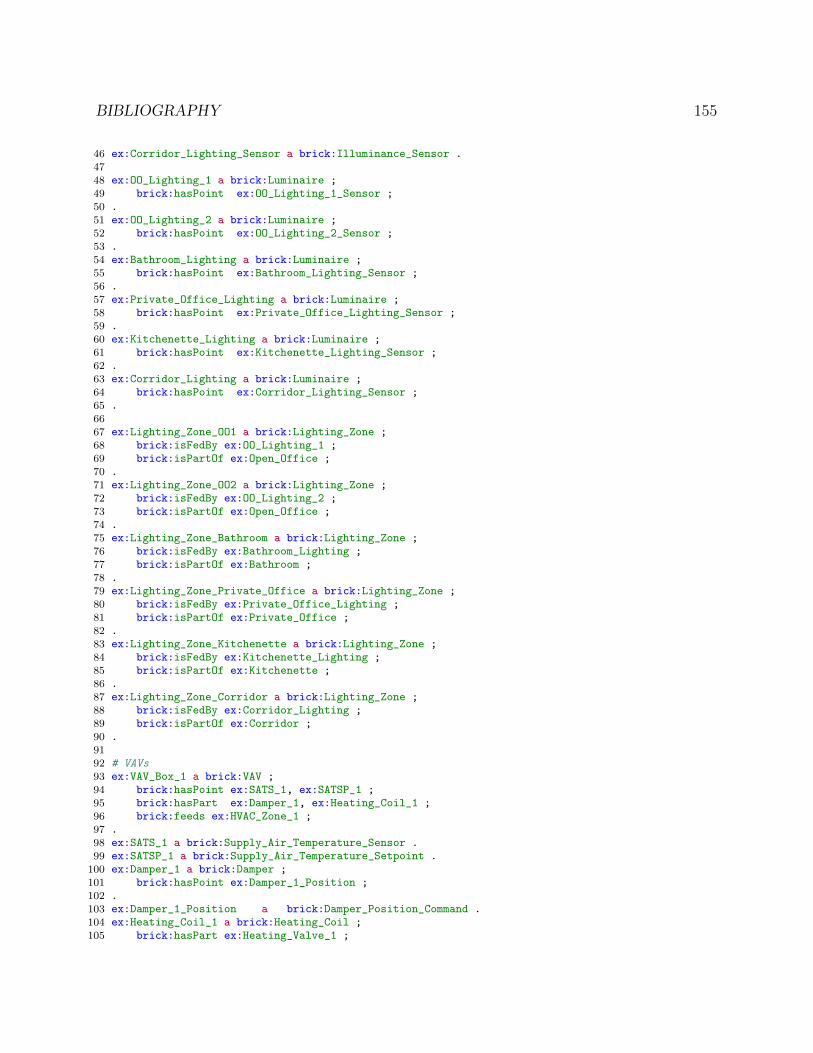
BIBLIOGRAPHY 155
46 ex:Corridor_Lighting_Sensor a brick:Illuminance_Sensor .47
48 ex:OO_Lighting_1 a brick:Luminaire ;49 brick:hasPoint ex:OO_Lighting_1_Sensor ;50 .51 ex:OO_Lighting_2 a brick:Luminaire ;52 brick:hasPoint ex:OO_Lighting_2_Sensor ;53 .54 ex:Bathroom_Lighting a brick:Luminaire ;55 brick:hasPoint ex:Bathroom_Lighting_Sensor ;56 .57 ex:Private_Office_Lighting a brick:Luminaire ;58 brick:hasPoint ex:Private_Office_Lighting_Sensor ;59 .60 ex:Kitchenette_Lighting a brick:Luminaire ;61 brick:hasPoint ex:Kitchenette_Lighting_Sensor ;62 .63 ex:Corridor_Lighting a brick:Luminaire ;64 brick:hasPoint ex:Corridor_Lighting_Sensor ;65 .66
67 ex:Lighting_Zone_OO1 a brick:Lighting_Zone ;68 brick:isFedBy ex:OO_Lighting_1 ;69 brick:isPartOf ex:Open_Office ;70 .71 ex:Lighting_Zone_OO2 a brick:Lighting_Zone ;72 brick:isFedBy ex:OO_Lighting_2 ;73 brick:isPartOf ex:Open_Office ;74 .75 ex:Lighting_Zone_Bathroom a brick:Lighting_Zone ;76 brick:isFedBy ex:Bathroom_Lighting ;77 brick:isPartOf ex:Bathroom ;78 .79 ex:Lighting_Zone_Private_Office a brick:Lighting_Zone ;80 brick:isFedBy ex:Private_Office_Lighting ;81 brick:isPartOf ex:Private_Office ;82 .83 ex:Lighting_Zone_Kitchenette a brick:Lighting_Zone ;84 brick:isFedBy ex:Kitchenette_Lighting ;85 brick:isPartOf ex:Kitchenette ;86 .87 ex:Lighting_Zone_Corridor a brick:Lighting_Zone ;88 brick:isFedBy ex:Corridor_Lighting ;89 brick:isPartOf ex:Corridor ;90 .91
92 # VAVs93 ex:VAV_Box_1 a brick:VAV ;94 brick:hasPoint ex:SATS_1, ex:SATSP_1 ;95 brick:hasPart ex:Damper_1, ex:Heating_Coil_1 ;96 brick:feeds ex:HVAC_Zone_1 ;97 .98 ex:SATS_1 a brick:Supply_Air_Temperature_Sensor .99 ex:SATSP_1 a brick:Supply_Air_Temperature_Setpoint .
100 ex:Damper_1 a brick:Damper ;101 brick:hasPoint ex:Damper_1_Position ;102 .103 ex:Damper_1_Position a brick:Damper_Position_Command .104 ex:Heating_Coil_1 a brick:Heating_Coil ;105 brick:hasPart ex:Heating_Valve_1 ;

BIBLIOGRAPHY 156
106 .107 ex:Heating_Valve_1 a brick:Heating_Valve ;108 brick:hasPoint ex:Valve_Command_1 ;109 .110 ex:Valve_Command_1 a brick:Valve_Command .111
112 ex:VAV_Box_2 a brick:VAV ;113 brick:hasPoint ex:SATS_2, ex:SATSP_2 ;114 brick:hasPart ex:Damper_2, ex:Heating_Coil_2 ;115 brick:feeds ex:HVAC_Zone_2 ;116 .117 ex:SATS_2 a brick:Supply_Air_Temperature_Sensor .118 ex:SATSP_2 a brick:Supply_Air_Temperature_Setpoint .119 ex:Damper_2 a brick:Damper ;120 brick:hasPoint ex:Damper_2_Position ;121 .122 ex:Damper_2_Position a brick:Damper_Position_Command .123 ex:Heating_Coil_2 a brick:Heating_Coil ;124 brick:hasPart ex:Heating_Valve_2 ;125 .126 ex:Heating_Valve_2 a brick:Heating_Valve ;127 brick:hasPoint ex:Valve_Command_2 ;128 .129 ex:Valve_Command_2 a brick:Valve_Command .130131
132 ex:Exhaust_Fan_1 a brick:Exhaust_Fan ;133 brick:isFedBy ex:Bathroom ;134 .135
136 # AHU137 ex:AHU a brick:AHU ;138 brick:hasPart ex:Supply_Fan, ex:Return_Fan,139 ex:Cooling_Coil, ex:Heating_Coil, ex:Filter,140 ex:Outside_Damper, ex:Mixed_Damper, ex:Exhaust_Damper ;141 brick:feeds ex:VAV_Box_1, ex:VAV_Box_2 ;142 brick:isFedBy ex:HVAC_Zone_1 ;143 brick:hasPoint ex:OATS, ex:RATS, ex:MATS, ex:SATS,144 ex:pre_hc_temp, ex:pre_cc_temp,145 ex:RAFS, ex:SAFS ;146 .147 ex:OATS a brick:Outside_Air_Temperature_Sensor .148 ex:RATS a brick:Return_Air_Temperature_Sensor .149 ex:MATS a brick:Mixed_Air_Temperature_Sensor .150 ex:SATS a brick:Supply_Air_Temperature_Sensor .151 ex:pre_hc_temp a brick:Temperature_Sensor .152 ex:pre_cc_temp a brick:Temperature_Sensor .153 ex:SAFS a brick:Supply_Air_Flow_Sensor .154 ex:RAFS a brick:Return_Air_Flow_Sensor .155156 ex:Supply_Fan a brick:Supply_Fan ;157 brick:hasPoint ex:SF_Speed ;158 .159 ex:SF_Speed a brick:Frequency_Command .160
161 ex:Return_Fan a brick:Return_Fan ;162 brick:hasPoint ex:SF_Speed ;163 .164 ex:RF_Speed a brick:Frequency_Command .165

BIBLIOGRAPHY 157
166 ex:Cooling_Coil a brick:Cooling_Coil ;167 brick:hasPoint ex:CC_Valve ;168 .169 ex:CC_Valve a brick:Cooling_Valve ;170 brick:hasPoint ex:CC_Valve_CMD ;171 .172 ex:CC_Valve_CMD a brick:Valve_Command ;173 .174 ex:Heating_Coil a brick:Heating_Coil ;175 brick:hasPoint ex:HC_Valve ;176 .177 ex:HC_Valve a brick:Heating_Valve ;178 brick:hasPoint ex:HC_Valve_CMD ;179 .180 ex:HC_Valve_CMD a brick:Valve_Command ;181 .182183 ex:Filter a brick:Filter .184185 ex:Outside_Damper a brick:Damper ;186 brick:hasPoint ex:Outside_Damper_Command ;187 .188 ex:Outside_Damper_Command a brick:Damper_Position_Command .189 ex:Mixed_Damper a brick:Damper ;190 brick:hasPoint ex:Mixed_Damper_Command ;191 .192 ex:Mixed_Damper_Command a brick:Damper_Position_Command .193 ex:Exhaust_Damper a brick:Damper ;194 brick:hasPoint ex:Exhaust_Damper_Command ;195 .196 ex:Exhaust_Damper_Command a brick:Damper_Position_Command .197
198
199 # controller200 ex:Controller a brick:Controller ;201 brick:controls ex:RF_Speed ;202 brick:hasInput ex:RAFS ;203 .204205 # internal topology of AHU206 ex:RATS brick:feeds ex:Return_Fan .207 ex:Return_Fan brick:feeds ex:RAFS .208 ex:RAFS brick:feeds ex:Exhaust_Damper, ex:Mixed_Damper .209 ex:Mixed_Damper brick:feeds ex:MATS .210 ex:Outside_Damper brick:feeds ex:MATS .211 ex:MATS brick:feeds ex:Filter .212 ex:Filter brick:feeds ex:pre_hc_temp .213 ex:pre_hc_temp brick:feeds ex:Heating_Coil .214 ex:Heating_Coil brick:feeds ex:pre_cc_temp .215 ex:pre_cc_temp brick:feeds ex:Cooling_Coil .216 ex:Cooling_Coil brick:feeds ex:SATS .217 ex:SATS brick:feeds ex:Supply_Fan .218 ex:Supply_Fan brick:feeds ex:SAFS .
Figure 9.1: Brick expression of the building and subsystems illustrated in Figure 2.2
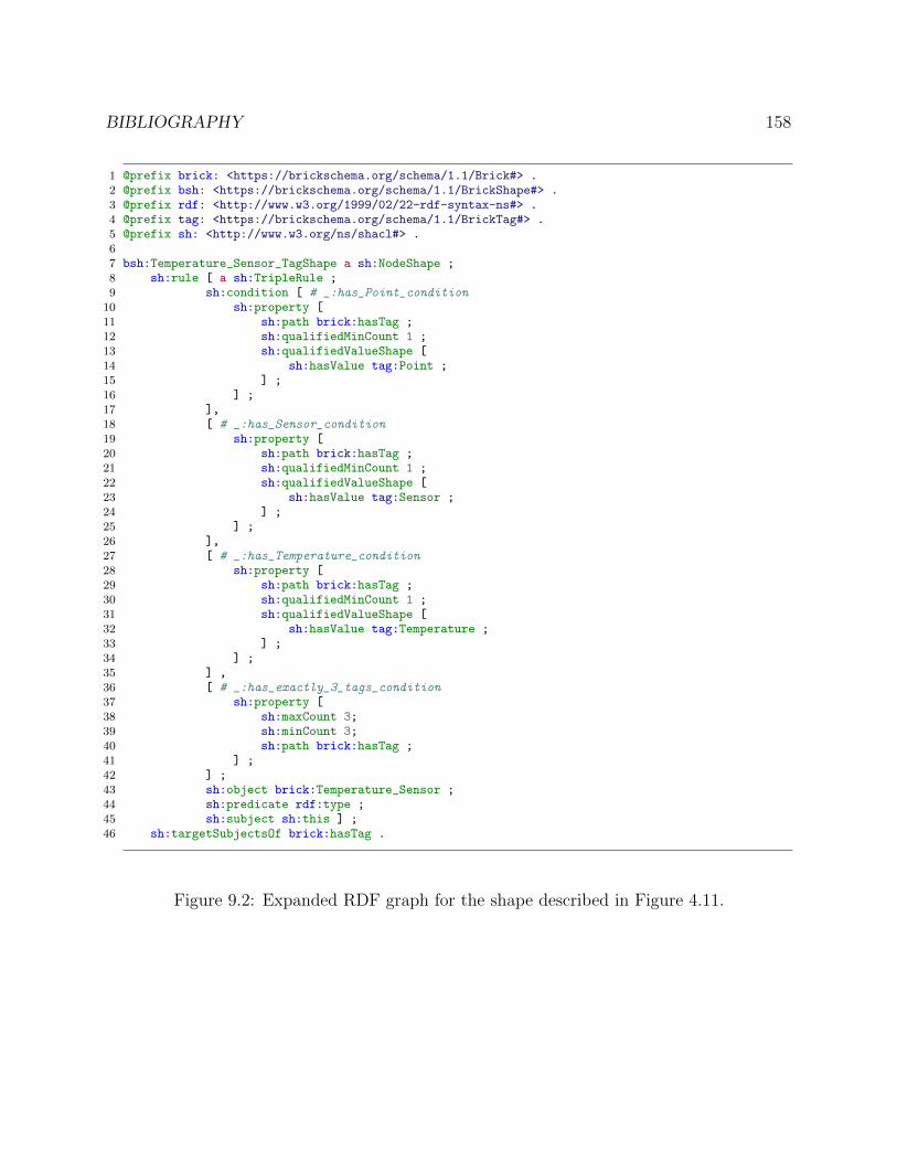
BIBLIOGRAPHY 158
1 @prefix brick: <https://brickschema.org/schema/1.1/Brick#> .2 @prefix bsh: <https://brickschema.org/schema/1.1/BrickShape#> .3 @prefix rdf: <http://www.w3.org/1999/02/22-rdf-syntax-ns#> .4 @prefix tag: <https://brickschema.org/schema/1.1/BrickTag#> .5 @prefix sh: <http://www.w3.org/ns/shacl#> .67 bsh:Temperature_Sensor_TagShape a sh:NodeShape ;8 sh:rule [ a sh:TripleRule ;9 sh:condition [ # _:has_Point_condition
10 sh:property [11 sh:path brick:hasTag ;12 sh:qualifiedMinCount 1 ;13 sh:qualifiedValueShape [14 sh:hasValue tag:Point ;15 ] ;16 ] ;17 ],18 [ # _:has_Sensor_condition19 sh:property [20 sh:path brick:hasTag ;21 sh:qualifiedMinCount 1 ;22 sh:qualifiedValueShape [23 sh:hasValue tag:Sensor ;24 ] ;25 ] ;26 ],27 [ # _:has_Temperature_condition28 sh:property [29 sh:path brick:hasTag ;30 sh:qualifiedMinCount 1 ;31 sh:qualifiedValueShape [32 sh:hasValue tag:Temperature ;33 ] ;34 ] ;35 ] ,36 [ # _:has_exactly_3_tags_condition37 sh:property [38 sh:maxCount 3;39 sh:minCount 3;40 sh:path brick:hasTag ;41 ] ;42 ] ;43 sh:object brick:Temperature_Sensor ;44 sh:predicate rdf:type ;45 sh:subject sh:this ] ;46 sh:targetSubjectsOf brick:hasTag .
Figure 9.2: Expanded RDF graph for the shape described in Figure 4.11.