self-contained interoperable controller model ucp-1
TRANSCRIPT
© 2013 Taco Electronic Solutions, Inc. 1
Application Guide 505-009
MPU2 Air Control – Pressure Dependent Multi-ZoneSelf-Contained Interoperable Controller Model UCP-1
SUPERSEDES: December 16, 2012 EFFECTIVE: January 16, 2013
Table of Contents
MPU2 . . . . . . . . . . . . . . . . . . . . . . . . . . . . . . . . . . . . . . 3Overview . . . . . . . . . . . . . . . . . . . . . . . . . . . . . . . . . 3Features. . . . . . . . . . . . . . . . . . . . . . . . . . . . . . . . . . 3
Purpose of This Guide . . . . . . . . . . . . . . . . . . . . . . . . . 3
Representations and Warranties . . . . . . . . . . . . . . . . . 4
Applicable Documentation . . . . . . . . . . . . . . . . . . . . . . 4
Installation Instructions . . . . . . . . . . . . . . . . . . . . . . . . . 5Precautions . . . . . . . . . . . . . . . . . . . . . . . . . . . . . . . 5General . . . . . . . . . . . . . . . . . . . . . . . . . . . . . . . . . . 5Static Electricity . . . . . . . . . . . . . . . . . . . . . . . . . . . . 5Location . . . . . . . . . . . . . . . . . . . . . . . . . . . . . . . . . . 5FCC Compliance . . . . . . . . . . . . . . . . . . . . . . . . . . . 5
Before Installing . . . . . . . . . . . . . . . . . . . . . . . . . . . . . . 6About this Document . . . . . . . . . . . . . . . . . . . . . . . . 6Inspecting the Equipment . . . . . . . . . . . . . . . . . . . . 6What is Not Included with this Equipment . . . . . . . . 6Equipment Location . . . . . . . . . . . . . . . . . . . . . . . . . 6Selecting a Power Source . . . . . . . . . . . . . . . . . . . . 6
Installation . . . . . . . . . . . . . . . . . . . . . . . . . . . . . . . . . . 6Mounting the Device . . . . . . . . . . . . . . . . . . . . . . . . 7Routing Cabling to the Device . . . . . . . . . . . . . . . . . 8Grounding the Device . . . . . . . . . . . . . . . . . . . . . . . 8
Wiring Information . . . . . . . . . . . . . . . . . . . . . . . . . . . . 9Connecting Input Devices . . . . . . . . . . . . . . . . . . . 11Connecting Output Devices . . . . . . . . . . . . . . . . . . 12Other Connections . . . . . . . . . . . . . . . . . . . . . . . . . 13
Specifications . . . . . . . . . . . . . . . . . . . . . . . . . . . . . . . 14Electrical . . . . . . . . . . . . . . . . . . . . . . . . . . . . . . . . 14Mechanical . . . . . . . . . . . . . . . . . . . . . . . . . . . . . . . 15
Application Description . . . . . . . . . . . . . . . . . . . . . . . . 16
Sequence of Operation. . . . . . . . . . . . . . . . . . . . . . . . 19Operational Mode . . . . . . . . . . . . . . . . . . . . . . . . . 19Occupancy Mode . . . . . . . . . . . . . . . . . . . . . . . . . . 20
Setpoint Calculations . . . . . . . . . . . . . . . . . . . . . . . 20Supply Air Setpoint Reset Curve . . . . . . . . . . . . . . 20Heating Sequence . . . . . . . . . . . . . . . . . . . . . . . . . 21Cooling Sequence . . . . . . . . . . . . . . . . . . . . . . . . . 23Economizer Operation . . . . . . . . . . . . . . . . . . . . . . 24Cutoff Temperatures . . . . . . . . . . . . . . . . . . . . . . . 25Dehumidification . . . . . . . . . . . . . . . . . . . . . . . . . . 25Bypass Damper . . . . . . . . . . . . . . . . . . . . . . . . . . . 26Analog Outputs . . . . . . . . . . . . . . . . . . . . . . . . . . . 26Fan Operation . . . . . . . . . . . . . . . . . . . . . . . . . . . . 26Fan Proof . . . . . . . . . . . . . . . . . . . . . . . . . . . . . . . . 26MPU2 and VAVD Communications . . . . . . . . . . . . 27Associating VAVDs . . . . . . . . . . . . . . . . . . . . . . . . 27Supply Air Temperature Monitoring . . . . . . . . . . . . 27Indoor Air Quality Compensation. . . . . . . . . . . . . . 27Smoke Detection . . . . . . . . . . . . . . . . . . . . . . . . . . 28Mixed Air Low Limit Detection . . . . . . . . . . . . . . . . 28Filter Status . . . . . . . . . . . . . . . . . . . . . . . . . . . . . . 28Real Time Clock (RTC) . . . . . . . . . . . . . . . . . . . . . 28Local Backup Schedule . . . . . . . . . . . . . . . . . . . . . 28Runtime Accumulations . . . . . . . . . . . . . . . . . . . . . 29Alarms and Events. . . . . . . . . . . . . . . . . . . . . . . . . 29Automatic Configuration . . . . . . . . . . . . . . . . . . . . 29
Controller Identification . . . . . . . . . . . . . . . . . . . . . . . 30Inputs . . . . . . . . . . . . . . . . . . . . . . . . . . . . . . . . . . . 30Outputs . . . . . . . . . . . . . . . . . . . . . . . . . . . . . . . . . 30Configuration . . . . . . . . . . . . . . . . . . . . . . . . . . . . . 31Alarms . . . . . . . . . . . . . . . . . . . . . . . . . . . . . . . . . . 37
Troubleshooting . . . . . . . . . . . . . . . . . . . . . . . . . . . . . 37Diagnostic LEDs . . . . . . . . . . . . . . . . . . . . . . . . . . 37Troubleshooting Tips . . . . . . . . . . . . . . . . . . . . . . . 38

iWorx® MPU2
2 505-009, Effective: January 16, 2013 © 2013 Taco Electronic Solutions, Inc.
THIS PAGE LEFT BLANK INTENTIONALLY
iWorx® MPU2
505-009, Effective: January 16, 2013 3 © 2013 Taco Electronic Solutions, Inc.
MPU2The MPU2 is a self-contained microprocessor-based controller for multiplexed zone package units. Applications include packaged rooftop DX units with up to four stages of cooling, or a floating point control valve, or a modulated output (valve or variable speed circulator) two stages of heating, or a floating point control valve, or a modulated output (valve or variable speed circulator) economizer, and bypass damper.
OverviewDigital inputs are provided for fan status, mixed air low limit indication, smoke detector, filter status and indoor air qual-ity (IAQ). Analog inputs are provided for mixed air temperature, return air humidity, supply air temperature, and supply duct static pressure. The MPU2 incorporates digital outputs in the form of triacs for fan start/stop, four cooling stages, two heating stages, and a two-position economizer. In addition, four analog outputs are provided to control cooling and heating outputs, a modulated economizer, and bypass damper.
The MPU2 is based on the LONWORKS® networking technology. The controller can be networked to a higher-level con-trol system for monitoring and control applications.
Features• Four stages of cooling, or a floating point control valve, or a modulated output (valve or variable speed circulator)• Two stages of heating, or a floating point control valve, or a modulated output (valve or variable speed circulator)• Modulated bypass damper • Digital or modulated economizer • Economizer enabled based on enthalpy calculations or dry bulb • Minimum cycle timers for stages • Runtime accumulation for heating, cooling, and fan • Dehumidification• Multiplexed control of 32 zones based on zone demand • Supply air temperature safety limits • Supply air temperature setpoint reset based on greatest zone demand• Time proportioned control of the staged outputs to reduce cycling • Proportional+Integral control of the modulated economizer, modulated heating modulated cooling and static pres-
sure• Local backup schedule• Mixed air low limit protection• Filter status, fan proof, freeze stat and smoke detection inputs• Fan control energized on a call for heating, cooling or ventilation• Automatic Heat/Cool changeover• IAQ compensation based on the IAQ input or zone controller alarm• Outside Air Temperature cutoffs• Real Time Clock• LONWORKS® interface to building automation systems• Automatic configuration with the LCI • Alarm/Event reporting
PURPOSE OF THIS GUIDEThe iWorx® MPU2 Application Guide provides application information for the MPU2 Controller.

iWorx® MPU2
4 505-009, Effective: January 16, 2013 © 2013 Taco Electronic Solutions, Inc.
The reader should understand basic HVAC concepts, intelligent environmental control automation, and basic LON-WORKS networking and communications. This Guide is written for:
• Users who engineer control logic• Users who set up hardware configuration• Users who change hardware or control logic• Technicians and field engineers
REPRESENTATIONS AND WARRANTIESThis Document is subject to change from time to time at the sole discretion of Taco Electronic Solutions, Inc. All updates to the Document are available at www.taco-hvac.com. When installing this product, it is the reader’s responsi-bility to ensure that the latest version of the Document is being used.
iWorx® products shall only be used for the applications identified in the product specifications and for no other pur-poses. For example, iWorx® products are not intended for use to support fire suppression systems, life support sys-tems, critical care applications, commercial aviation, nuclear facilities or any other applications where product failure could lead to injury to person, loss of life, or catastrophic property damage and should not be used for such purposes.
Taco Electronic Solutions, Inc. will not be responsible for any product or part not installed or operated in conformity with the Document and instructions or which has been subject to accident, disaster, neglect, misuse, misapplication, inade-quate operating environment, repair, attempted repair, modification or alteration, or other abuse. For further informa-tion, please refer to the last page of this Document for the company’s Limited Warranty Statement, which is also issued with the product or available at www.taco-hvac.com.
APPLICABLE DOCUMENTATIONTable 1: Applicable Documentation
Description Audience PurposeiWorx® MPU2 Application Guide, Document No. 505-009 (this docu-ment)
– Application Engineers– Wholesalers– Contractors– Start-up Technicians– End user
Provides instructions for setting up and using the iWorx® MPU2.
iWorx® VAV Application Guide, Document No. 505-010
– Application Engineers– Installers– Service Personnel– Start-up Technicians– End user
Provides instructions for setting up and using the iWorx® VAV controller.
iWorx® LCI Application Guide, Doc-ument No. 505-002
– Application Engineers– Installers– Service Personnel– Start-up Technicians– End user
Provides instructions for setting up and using the iWorx® Local Control Interface.
http://iWorxWizard.taco-hvac.com – Application Engineers– Wholesalers– Contractors
An on-line configuration and submittal package generator based on user input. Automatically generates bill of materials, sequence of operations, flow diagrams, wiring diagrams, points and specifications.
Additional Documentation LonWorks FTT-10A Free Topology Transceiver User’s Guide, published by Echelon Cor-poration. It provides specifications and user instructions for the FTT-10A Free Topology Transceiver. See also: www.echelon.com/support/documentation/manuals/transceivers.
iWorx® MPU2
505-009, Effective: January 16, 2013 5 © 2013 Taco Electronic Solutions, Inc.
INSTALLATION INSTRUCTIONS
Precautions
GeneralThis symbol is intended to alert the user to the presence of important installation and maintenance (servic-ing) instructions in the literature accompanying the equipment.
WARNING: Electrical shock hazard. Disconnect ALL power sources when installing or servicing this equipment to prevent electrical shock or equipment damage.
Make all wiring connections in accordance with these instructions and in accordance with pertinent national and local electrical codes. Use only copper conductors.
Static ElectricityStatic charges produce voltages that can damage this equipment. Follow these static electricity precautions when han-dling this equipment.
• Work in a static free area.• Touch a known, securely grounded object to discharge any charge you may have accumulated.• Use a wrist strap when handling printed circuit boards. The strap must be secured to earth ground.
LocationAvoid locations where corrosive fumes, excessive moisture, vibration or explosive vapors are present.
Avoid electrical noise interference. Do not install near large contactors, electrical machinery, or welding equipment.
This equipment is suitable for indoor use only. Preferably, or as required by National Electrical Code, the unit is intended to be installed within an electrical control enclosure. Operate where ambient temperatures do not exceed 140 °F (60 °C) or fall below 32 °F (0 °C) and relative humidity does not exceed 90%, non-condensing.
FCC ComplianceThis equipment has been tested and found to comply with the limits for a Class A digital device, pursuant to Part 15 of the FCC rules. These limits are designed to provide reasonable protection against harmful interference. This equip-ment can radiate radio frequency energy and, if not installed and used in accordance with the instructions, may cause harmful interference to radio communications. However, there is no guarantee that interference will not occur in a par-ticular installation. If this equipment does cause harmful interference to radio or television reception, which can be determined by turning the equipment off and on, the user is encouraged to try to correct the interference by one or more of the following measures:
• Reorient or relocate the receiving antenna.• Increase the separation between the equipment and the receiver.• Connect the equipment to a power source different from that to which the receiver is connected.• Consult the equipment supplier or an experienced radio/TV technician for help.
You are cautioned that any changes or modifications to this equipment not expressly approved in these instructions could void your authority to operate this equipment in the United States.

iWorx® MPU2
6 505-009, Effective: January 16, 2013 © 2013 Taco Electronic Solutions, Inc.
BEFORE INSTALLING
About this DocumentThe instructions in this manual are for the MPU2 controller, which supports one multiplexed package unit.
Inspecting the EquipmentInspect the shipping carton for damage. If damaged, notify the carrier immediately. Inspect the equipment for damage. Return damaged equipment to the supplier.
What is Not Included with this Equipment• A power source for the equipment electronics and peripheral devices.• Tools necessary to install, troubleshoot and service the equipment.• The screws or DIN rail needed to mount the device.• Peripheral devices, such as sensors, actuators, etc.• Cabling, cabling raceway, and fittings necessary to connect this equipment to the power source, FTT-10A network
and peripheral devices.
Equipment LocationAbide by all warnings regarding equipment location provided earlier in this document.
Optimally, the equipment should be installed within a secure enclosure.
If the equipment is to be installed outdoors, it must be contained within a protective enclosure. The enclosure must maintain internal temperature and humidity within the ranges specified for this equipment.
The equipment must be installed within 500 feet of all input peripherals (smoke detectors, sensors, etc.) that will be connected to the equipment.
Selecting a Power SourceThis equipment requires a UL recognized Class 2 external power source (not supplied) to operate. The controller power input requires a voltage of 24 Volts AC.
To calculate power source current requirements, add the power consumption of all peripheral devices to that of the controller.
The controller and sensor power supplies can use the same power source. If both are using the same power source, the loads must have EMF protection. This protection can be integral to the load, or installed in the 24 VAC wiring across the load’s coil.
To provide necessary RFI and transient protection, the controller’s ground (GND) pin (T40) must be connected to earth ground or the earth ground of the packaged unit’s enclosure ground. Failure to properly ground the controller may cause it to exceed FCC limits. Excessive noise could also produce inaccurate sensor data. The power source must be capable of operating with this connection to ground.
INSTALLATIONWarning: Electrical shock hazard. To prevent electrical shock or equipment damage, disconnect ALL power sources to controllers and loads before installing or servicing this equipment or modifying any wir-ing.

iWorx® MPU2
505-009, Effective: January 16, 2013 7 © 2013 Taco Electronic Solutions, Inc.
Mounting the Device1.Select a mounting location. Enclosure mounting is recommended. 2.Hold the controller on the panel you wish to mount it on. With a marker or pencil mark the mounting locations on
the panel. 3.Using a small drill bit pre-drill the mounting holes. 4.Using two #6 pan head screws, mount the controller to the panel. 5.Wire the controller (See Routing Cabling to the Device). Figure 1: Mounting Dimensions

iWorx® MPU2
8 505-009, Effective: January 16, 2013 © 2013 Taco Electronic Solutions, Inc.
Routing Cabling to the DeviceCabling used to connect the power source and cabling used to connect the FTT-10A network must remain separated within the control enclosure and wiring conduit.
Grounding the DeviceThe ground terminal (T40) must be securely connected to earth ground. Failure to properly ground this equipment will result in improper operation. Improper grounding may also increase the risk of electrical shock and may increase the possibility of interference with radio/TV reception.
For best performance, connect the power supply common terminal (T38) to the same external point as the ground terminal (T40).

iWorx® MPU2
505-009, Effective: January 16, 2013 9 © 2013 Taco Electronic Solutions, Inc.
WIRING INFORMATIONWARNING: Terminals 6, 9, 12, 15, 18, and 38 are connected internally on all MPU2 controllers. Disconnect ALL power sources when installing or servicing this equipment to prevent electrical shock or equipment damage.
Figure 2: Typical MPU2 Wiring - Power Sourcing

iWorx® MPU2
10 505-009, Effective: January 16, 2013 © 2013 Taco Electronic Solutions, Inc.
Figure 3: Typical MPU2 Wiring - Power Sinking

iWorx® MPU2
505-009, Effective: January 16, 2013 11 © 2013 Taco Electronic Solutions, Inc.
Figure 4: Typical MPU2 Wiring - Power Isolated
Connecting Input Devices
Return Humidity (RAH) To connect the Return Air Humidity sensor to the unit, connect the positive wire from the sensor to RAH (T19) and the other wire to the adjacent common (T18). The sensor must be of the 0-10 Volt type.

iWorx® MPU2
12 505-009, Effective: January 16, 2013 © 2013 Taco Electronic Solutions, Inc.
If global indoor air humidity readings are being provided over the network, it is not necessary to attach a return air humidity sensor directly to the MPU2.
Mixed Air (MAT)To connect the Mixed Air thermistor to the unit, attach one wire from the thermistor to MAT (T17) and the other wire to the adjacent common (T18). The thermistor used must be 10K Precon Type III.
Supply Air (SAT)To connect the Supply Air thermistor to the unit, attach one wire from the thermistor to SAT (T16) and the other wire to the adjacent common (T15). The thermistor used must be 10K Precon Type III.
Smoke Detector (SMK)To connect the smoke detector switch to the digital input, attach one wire of the contact to SMK (T14) and the other wire to the adjacent common (T15). This must be a dry contact normally open switch. This input is for indication only. A separate smoke detector should be wired into a fire alarm system if the generation of a fire alarm is required.
Filter (FIL)To connect the filter switch to the digital input, attach one wire of the contact to FIL (T13) and the other wire to the adja-cent common (T12). This must be a dry contact normally open switch.
Mixed Air Low Limit Indication (MLL)To connect the low limit indication switch to the digital input, attach one wire of the contact to MLL (T11) and the other wire to the adjacent common (T12). This must be a dry contact normally open switch.
Indoor Air Quality (IAQ)To connect the digital CO2 level sensor to the unit, attach one wire from the sensor to IAQ (T10) and the other wire to the adjacent common (T9). The sensor must provide a contact closure when the CO2 limit is exceeded. For a digital sensor, this must be a dry contact normally open switch. For an analog sensor, it must be of the 0-10V type.
Static Pressure (SPR)To connect the static pressure transducer to the analog input, connect the positive wire from the sensor to SPR (T8) and the other wire to the adjacent common (T9). The sensor must be of the 0 to 10 V type.
Return Air Temperature (RAT)To connect the return air temperature thermistor to the analog input, attach one wire of the sensor to RAT (T7) and the other wire to the adjacent common (T6).
Fan Proof (FNP)To connect the fan proof switch to the digital input, attach one wire of the contact to FNP (T5) and the other wire to the adjacent common (T6). This must be a dry contact, normally closed switch. If you are not providing a fan proof input, T5 and T6 must be shorted (jumpered) together.
Connecting Output Devices
Modulated Economizer (ECNM)The modulated economizer output can be set to 0-10 V max through the control logic. Connect the positive wire from the damper actuator to ECNM (T37) and the other wire to the adjacent common (T36). See preceding figures for details.
Modulated Heating (HTGM)The modulated heating output can be set to 0-10 V max through the control logic. Connect the positive wire from the heating output to ECNM (T35) and the other wire to COM (T36). See preceding figures for details.

iWorx® MPU2
505-009, Effective: January 16, 2013 13 © 2013 Taco Electronic Solutions, Inc.
Modulated Cooling (CLGM)The modulated cooling output can be set to 0-10 V max through the control logic. Connect the positive wire from the cooling output to CLGM (T34) and the other wire to COM (T33). See preceding figures for details.
Bypass Damper (BYP)The bypass damper output can be set to 0-10 VDC max through the control logic. Connect the positive wire from the damper actuator to BYP (T32) and the other wire to the adjacent common (T33). See preceding figures for details.
Cooling Stage 1 or Cooling Floating Point Valve Open (C1)The cooling stage output must be connected to a 24 VAC pilot relay if the load is greater than 1 Amp. See preceding figures for details. If the load is less than 1 Amp, connect cooling stage 1 to C1 (31) and TC12 (30). For control of a floating point valve, connect C1 as the valve open signal.
Cooling Stage 2 or Cooling Floating Point Valve Close (C2)The cooling stage output must be connected to a 24 VAC pilot relay if the load is greater than 1 Amp. See preceding figures for details. If the load is less than 1 Amp, connect cooling stage 2 to C2 (29) and TC12 (30). For control of a floating point valve, connect C2 as the valve close signal.
Cooling Stage 3 (C3)The cooling stage output must be connected to a 24 VAC pilot relay if the load is greater than 1 Amp. See preceding figures for details. If the load is less than 1 Amp, connect to C3 (T28) and TC34 (T27).
Cooling Stage 4 (C4)The cooling stage output must be connected to a 24 VAC pilot relay if the load is greater than 1 Amp. See preceding figures for details. If the load is less than 1 Amp, connect to C4 (T26) and TC34 (T27).
Heating Stage 1 or Heating Floating Point Valve Open (H1)The heating stage output must be connected to a 24 VAC pilot relay if the load is greater than 1 Amp. See preceding figures for details. If the load is less than 1 Amp, connect heating stage 1 to H1 (T25) and TC56 (24). For control of a floating point heating valve, connect H1 (T25) as the valve open signal. TC56 (T24) is the common.
Heating Stage 2 or Heating Floating Point Valve Close (H2)The heating stage output must be connected to a 24 VAC pilot relay if the load is greater than 1 Amp. See preceding figures for details. If the load is less than 1 Amp, connect heating stage 2 to H1 (T23) and TC56 (T24). For control of a floating point heating valve, connect H2 (T23) as the valve close signal. TC56 (T24) is the common.
Fan (FAN)The fan output must be connected to a 24 VAC pilot relay if the load is greater than 1 Amp. See preceding figures for details. If the load is less than 1 Amp, connect the fan to FAN (T22) and TC78 (T21).
Digital Economizer (ECD)The digital economizer output must be connected to a 24 VAC pilot relay if the load is greater than 1 Amp. See preced-ing figures for details. If the load is less than 1 Amp, connect the economizer to ECD (T20) and TC78 (T21).
Other Connections
Network (LON)Network wiring must be twisted pair. One network wire must be connected to terminal NETA (T1) and the other network wire must be connected to terminal NETB (T2). Polarity is not an issue since an FTT-10A network is used for commu-nications.

iWorx® MPU2
14 505-009, Effective: January 16, 2013 © 2013 Taco Electronic Solutions, Inc.
Power (PWR)Connect one output wire from a 24 VAC power supply to PWR (T39) and the other output wire from the power supply to the adjacent common terminal (T38).
Ground (GND)Terminal GND (T40) must be connected to earth ground. Failure to properly ground this equipment will result in improper operation. Improper grounding may also increase the risk of electrical shock, and may increase the possibility of interference with radio and TV reception.
SPECIFICATIONS
Electrical
Inputs• Cabling: twisted shielded pair, 18 AWG recommended—500 feet max. (152 meters)• Resolution: 10 bit
Mixed Air Low Limit, Filter Status, Smoke Detect, Local IAQ Alarm• Dry Contact• Normally Open• 5 Volts DC Max
Fan Proof• Dry Contact• Normally Closed
Return Air Humidity, Static Pressure• 0 - 10 Volts DC
Mixed Air Temperature, Supply Air Temperature, Return Air Temperature• Precon Type III 10K thermistor
Outputs Fan Start/Stop, Heating Stage 1, Heating Stage 2, Cooling Stage 1, Cooling Stage 2, Cooling Stage 3, Cool-ing Stage 4, Digital Economizer
• 24 Volts AC• 1A @ 50C, 0.5A @ 60C, limited by the Class 2 supply rating
Modulated Economizer, Bypass Damper• 0-10 Volts DC• 2K Ohm minimum load• 8 bit resolution
PowerPower Requirements
• 24VAC (20VAC to 28VAC), requires an external Class 2 supplyPower Consumption
• 7.2W with no external loads, maximum limited by the Class 2 supply rating

iWorx® MPU2
505-009, Effective: January 16, 2013 15 © 2013 Taco Electronic Solutions, Inc.
Recommended Sensor Wire
FTT-10A Network• Speed: 78KBPS• Cabling: Maximum node-to-node distance: 1312 feet (400 meters)• Maximum total distance: 1640 feet (500 meters)
For detailed specifications, refer to the FTT-10A Free-Topology Transceiver User’s Guide published by Echelon Corpo-ration (www.echelon.com/support/documentation/manuals/transceivers).
Mechanical
Housing • Dimensions: 5.55” (141mm) high, 6.54” (166 mm) wide, 1.75” deep (44 mm)• ABS
Weight • Controller Weight: 0.70 pounds (0.32 kilograms)• Shipping Weight: 1.0 pounds (0.46 kilograms)
Electronics• Processor: 3150 Neuron 10 MHz• Flash: 48 Kilobytes • SRAM: 8 Kilobytes • Termination: 0.197” (5.0 mm) Pluggable Terminal Blocks, 14-22 AWG
Environmental • Temperature: 32 °F to 140 °F (0 °C to 60 °C)• Humidity: 0 to 90%, non-condensing
Agency Listings• UL Listed for US and Canada, Energy Management Equipment PAZX and PAZX7.
Agency Compliances• FCC Part 15 Class A
Cable Type Pairs Details Taco Catalog No.18AWG 1 Stranded Twisted Shielded Pair, Plenum WIR-018
Cable Type Pairs Details Taco Catalog No.Level 4 22AWG (0.65mm) 1 Unshielded, Plenum, U.L. Type CMP WIR-022

iWorx® MPU2
16 505-009, Effective: January 16, 2013 © 2013 Taco Electronic Solutions, Inc.
APPLICATION DESCRIPTIONThe MPU2 is a multiplexed package unit controller that permits a single zone package unit to operate multiple zones. Figure 5 and Figure 6 illustrate typical MPU2 applications. The MPU2 operates in conjunction with up to 32 multiplexed zone controllers. The control is achieved by multiplexing the primary supply air between cooling and heating based on the various demands from the Zone Controllers. In addition to multiplexing, the MPU2 controls an economizer and bypass damper.
Figure 5: Multiplexed Package Unit - Staged Heating & Cooling, Modulated Economizer
The starting and stopping of the supply air fan is controlled by the MPU2. The fan is energized when the there is a call for heating or cooling from the Zone Controllers. During the occupied periods, the fan can be configured to run continu-ously.
The enthalpies of the outside and inside air are calculated periodically. A comparison is performed to determine if “free cooling” is available. If “free cooling” is available, the economizer is enabled. Optionally, free cooling can be determined by a dry bulb comparison of the outside air temperature and average zone temperature.
The economizer can be configured as two-position (digital) or modulated (analog). If enabled, the two position econo-mizer output is energized when there is a call for cooling. It is used as the first stage of cooling to take advantage of the energy savings. The two-position economizer output is off when the economizer is disabled.
When “free cooling” is available, the modulated economizer position is calculated by a Proportional + Integral (P+I) control loop based on the mixed air temperature and setpoint. As the temperature increases above the mixed air set-point, the economizer damper is modulated open. The economizer is modulated closed as the temperature decreases below the mixed air setpoint. The economizer is modulated to its minimum position when the economizer is disabled. The economizer can optionally be disabled during unoccupied periods.
The bypass damper operates to maintain a configurable system static pressure setpoint. The bypass damper position is calculated by a Proportional + Integral (P+I) control loop based on the measured static pressure and setpoint. As the pressure increases above the pressure setpoint, the bypass damper is modulated open. The bypass damper is modu-lated closed as the pressure decreases below the pressure setpoint.
Heating and cooling changeover setpoints are provided to prevent zone thermal shock during mode changes.

iWorx® MPU2
505-009, Effective: January 16, 2013 17 © 2013 Taco Electronic Solutions, Inc.
Figure 6: Multiplexed Zone Control System
An indoor air quality input is provided to monitor the Indoor Air Quality (IAQ). It can accept a digital CO2 sensor provid-ing a contact closure, or an analog CO2 sensor. In addition, an alarm condition can be signaled by one of the Zone Controllers. When an alarm condition exists, the MPU2 energizes the supply air fan and override the static pressure setpoint to the IAQ alarm setpoint. The economizer is overridden to the minimum ventilation position. After a program-mable time delay, the economizer is overridden open to supply fresh air to the zones. Optional heating and cooling out-side air temperature lockouts are provided for the economizer. If the IAQ sensor is connected directly, an IAQ alarm is reported to the LCI and all of the Zone Controllers.
The MPU2 scans all associated Zone Controllers to collect system demand data. The total heating and cooling demands are accumulated. The greatest demand determines the control mode.
When the system cooling demand is greater than the system heating demand, the system enters the cooling mode.
When the system heating demand is greater than the system cooling demand, the system enters the heating mode.
Heating is accomplished through control of up to two stages of electric heating, or control of one floating point heating valve or control of one analog output (valve or variable speed circulator). Cooling is accomplished through control of up to four stages of cooling, or one floating point cooling valve or control of one analog cooling output (valve or variable speed circulator).
The cooling stages are sequenced with a timed-proportioned control algorithm to minimize excessive cycling. The sequencing is based on the measured supply air temperature, and the cooling setpoint. The cooling and heating demands are continually re-evaluated during the cooling mode of operation. The controller is capable of switching to the heating mode when the temperature demand is greater for heating. The cooling stages are interlocked with the economizer control. If the two-position economizer is employed, the stages sequence on after the economizer.
The heating stages are sequenced with a timed-proportioned control algorithm to minimize excessive cycling. The sequencing is based on the measured supply air temperature, and the heating setpoint. The cooling and heating demands are continually re-evaluated during the heating mode of operation. The controller is capable of switching to the cooling mode when the temperature demand is greater for cooling.
If configured for modulated analog output (valve or variable speed circulator) the cooling output position is calculated by a P + I control loop based on the supply temperature and the cooling setpoint. As the temperature increases above the cooling setpoint, the cooling output will be modulated open. The cooling output will be modulated closed as the temperature decreases below the cooling setpoint.
The heating output (valve or variable speed circulator) position is calculated by a P +I control loop based on the supply temperature and the heating setpoint. As the temperature decreases below the heating setpoint, the heating output will be modulated open. The heating output will be modulated closed as the temperature increases above the heating set-point.

iWorx® MPU2
18 505-009, Effective: January 16, 2013 © 2013 Taco Electronic Solutions, Inc.
If configured for a floating point valve control, the cooling valve is calculated by a P + I control loop based on the supply temperature and cooling setpoint. As the temperature increases above the cooling setpoint, the valve will be modulated open. The valve will be modulated closed as the temperature decreases below the cooling setpoint.
If configured for a floating point valve control, the heating valve is calculated by a P + I control loop based on the supply temperature and cooling setpoint. As the temperature decreases below the heating setpoint, the valve will be modu-lated open. The valve will be modulated closed as the temperature increases above the heating setpoint.
In both the heating and cooling modes, the supply air temperature setpoint may be reset by the greatest zone temper-ature.
The controller optionally has the capability of monitoring the supply air temperature to determine if the heating and cooling are operating properly. During the cooling mode, if the supply air temperature fails to drop below the cooling operational limit after a pre-determined time period, the cooling stages shut down and a cooling failed alarm is reported to the LCI.
During the heating mode, if the supply air temperature fails to rise above the heating operational limit after a pre-deter-mined time period, the heating stages shut down and a heating failed alarm is reported to the LCI.
As a safety device, the controller can optionally monitor the supply air temperature to determine if the heating stages have failed on. If the supply air temperature rises above the heating high limit setpoint, the fan energizes. If the supply air temperature does not drop below the setpoint after a pre-programmed time delay, the bypass damper is overridden closed. A heating high limit exceeded alarm is reported to the LCI and all of the zone controllers.
The controller operates in one of two states: occupied or unoccupied. The LCI determines the active operating mode. An optional backup schedule is provided for cases when the LCI is not available.
A digital input is provided to monitor the fan proof. If the fan is energized and no air flow is detected after 30 seconds, the controller turns off all stages of heating and cooling along with the supply air fan. The controller returns to normal operation after it is reset. An alarm is reported to the LCI when this condition exists.
A digital input is provided on the controller to monitor the status of the air filter. An external pressure switch is wired to the input to determine when the filter becomes dirty. An alarm is reported to the LCI when this condition exists.
Mixed air low limit protection is provided through a digital input. If a low limit condition exists, the controller turns off all stages of heating and cooling along with the supply air fan. An alarm is reported to the LCI when this condition exists. If configured for either analog or floating point valve, the output will open 100% to prevent freezing of the coils. The con-troller returns to normal operation after it is reset. Following the reset there is a 10 minute delay before the mixed air low limit is checked again.
The controller monitors the runtime of the cooling stages, heating stages, and fan. When any of the runtimes exceeds the programmable limit, a maintenance alarm is reported to the LCI.
When the Return Air Humidity rises above the humidity setpoint, dehumidification is enabled by enabling the cooling stages, if modulated cooling is enabled; the cooling output goes to 100%. Dehumidification is disabled, when return air humidity drops below the setpoint by 3%.
iWorx® MPU2
505-009, Effective: January 16, 2013 19 © 2013 Taco Electronic Solutions, Inc.
SEQUENCE OF OPERATIONThis section describes the detailed sequence of operation for the MPU2 control algorithms.
Operational ModeThe MPU2 operates in one of four operating modes: primary heating, primary cooling, primary fan only, and primary off. The operating mode determines whether warm or cool air is supplied to the zone controllers. The MPU2 determines the operational mode based on the zone demand information supplied by each of the associated zone controllers. At least once every 5 seconds, a different zone controller is polled. Each zone controller transfers its zone demand infor-mation to the MPU2 over the communications network. The following information is transferred to the MPU2 controller:
• Zone temperature• Calculated Heating Setpoint• Calculated Cooling Setpoint• IAQ Sensor Status (safe, alarm)• Local Alarm (VAVD shutdown)• Occupancy Mode (occupied, unoccupied, occupied extension)• Supplemental heat status (on, off)
A zone heating demand is recognized when the zone temperature of a zone is at least 1.0 ° F below the calculated heating setpoint. The total heating demand is the sum of all zones requiring heating.
A zone cooling demand is recognized when the zone temperature of a zone is at least 1.0 ° F above the calculated cooling setpoint. The total cooling demand is the sum of all zones requiring cooling.
The system operational mode is determined by the greatest total demand value. When there is demand for both heat-ing and cooling, the system switches between heating and cooling based on a configurable changeover time. Note that minimum cycle times for the heating and cooling stages are enforced before an operational mode change can take place. Also, a minimum 5-minute off-cycle is enforced before switching modes and following controller startup or reset.
When all zone demands have been satisfied (zone demand = 0), the operational mode is set to primary off indicating no heating or cooling is being provided. When there is neither heating nor cooling, but the supply fan is on, the opera-tional mode is set to primary fan only.
The heating mode can be disabled during warm weather by setting the outdoor air temperature heating lockout Max OAT Heat. If the OAT is above the heating lockout temperature, the primary heating mode is disabled and the MPU2 can only be in the primary off or primary cooling modes. This feature requires that a controller that broadcasts the OAT, such as an iWorx® ASM2, be installed on the network.
The cooling mode can be disabled during cold weather by setting the outdoor air temperature cooling lockout Min OAT Cool. If the OAT is below the cooling lockout temperature, the primary cooling mode is disabled and the controller can only be in the primary off or primary heating modes. This feature requires that a controller that broadcasts the OAT, such as an ASM2 be installed on the network.
The economizer can be disabled during warm or cold weather by setting the outdoor air temperature economizer Maxand Min OAT Econ settings. If the OAT is above the Max lockout temperature or below the Min OAT temperature, the economizer is disabled and forced to its minimum fresh air position. The controller can only be in the primary off, pri-mary heating or primary cooling modes. This feature requires that a controller that broadcasts the OAT, such as an ASM2 be installed on the network.
The MPU2 can also be configured to only enter primary cooling or primary heating mode when a minimum number of zones require cooling or heating. Setting the Zone Limit to a higher number prevents a small number of zones from affecting the desired operating mode of the whole space by instructing the MPU2 to not change operating modes until at least that number of zones require heating or cooling.
The current operational mode information is periodically transferred to the VAVD over the communications network. The following information is transferred to the VAVD from the primary air source controller:
• Operational Mode (primary cool, primary heat, primary fan only, primary off)

iWorx® MPU2
20 505-009, Effective: January 16, 2013 © 2013 Taco Electronic Solutions, Inc.
• Alarm Conditions (IAQ Mode, Heat Failed On)• Supply Air Temperature
Occupancy ModeA remote device on the network (such as an LCI) provides the current occupancy mode. There are two modes of occu-pancy: occupied and unoccupied.
In addition, the current occupancy mode is periodically retrieved from each of the zone controllers. If at least one zone controller is currently in occupancy extension mode the occupancy mode is overridden to the occupied state.
The current occupancy mode can affect the operation of the economizer, fan and bypass damper.
Additionally the heating and cooling setpoints may be reset based on the greatest zone demand.
Setpoint CalculationsThe supply air heating and cooling setpoints are programmable values. The effective setpoint is a calculated value based on the current operating mode. The effective setpoint is set to the heating setpoint when the operational mode is heating. It is set to the cooling setpoint when the operational mode is cooling.
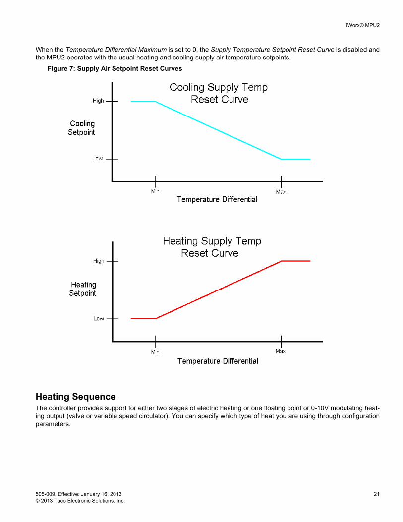
Supply Air Setpoint Reset CurveIf the Supply Temperature Setpoint Reset Curve is enabled, the MPU2 keeps track of the differential between each zone's space temperature and its temperature setpoint. The MPU2 selects the zone with the greatest differential and uses that Temperature Differential to adjust the Supply Temperature Setpoint.
If the Temperature Differential is less than the Temperature Differential Minimum, then the Supply Temperature Set-point Low will be used. If the Temperature Differential is greater than the Temperature Differential Maximum, then the Supply Temperature Setpoint High is used.
When the Temperature Differential is between the Temperature Differential Maximum and Temperature Differential Minimum, the Supply Temperature Setpoint is linearly interpolated between the Supply Setpoint High and Supply Set-point Low.
iWorx® MPU2
505-009, Effective: January 16, 2013 21 © 2013 Taco Electronic Solutions, Inc.
When the Temperature Differential Maximum is set to 0, the Supply Temperature Setpoint Reset Curve is disabled and the MPU2 operates with the usual heating and cooling supply air temperature setpoints.
Figure 7: Supply Air Setpoint Reset Curves
Heating SequenceThe controller provides support for either two stages of electric heating or one floating point or 0-10V modulating heat-ing output (valve or variable speed circulator). You can specify which type of heat you are using through configuration parameters.

iWorx® MPU2
22 505-009, Effective: January 16, 2013 © 2013 Taco Electronic Solutions, Inc.
Heating StagesThe heating sequence is initiated when the current operating mode calls for heat. The electric heating stages are sequenced based on the supply air temperature, heating setpoint and control band. When the supply air temperature drops below the heating setpoint minus the control band, a stage is turned on. If the supply air temperature remains below the control band for an additional time-period, the next available stage is turned on. If all zone temperature read-ings are within 0.5 °F of their setpoints, the next stage does not cycle on. This cycle continues until all available stages have been energized.
As the supply air temperature rises above the heating setpoint, the first available stage is turned off. If the supply air temperature remains above the heating setpoint for an additional time-period, the next available stage is turned off. This cycle continues until all available stages have been de-energized. If the supply air temperature rises above the heating setpoint plus control band all of the stages immediately cycle off.
Figure 8: Staged Heating Sequence - Occupied Mode T1 = Stage Cycle Time
Calculated Heating Setpoint
Heating Control Band
T2 = Stage Cycle Time x 2
Stage 1 On
Stage 2 On Stage 2 Off
Stage 1 Off
T1 T2T1T2
Temperature
Heating with Floating Point ControlThe heating stage outputs can be configured for floating point control of a heating valve. Floating point control is enabled when heating stages are set to zero and the Heating Valve Travel Time is non-zero. The heating stage 1 out-put is the valve open signal and the heating stage 2 output is the valve close signal.
After a reset, the floating point valve is calibrated by closing the valve for a period of the travel time. This ensures that the valve is fully closed. When the valve is at its calculated 0% or 100% position, the valve is overdriven for 30 seconds to ensure that the valve is fully closed or open.
The floating point control is similar to the heating modulated algorithm. If the supply temperature is below the heating setpoint, the valve is driven open. When the supply temperature is above the heating setpoint, the vale is driven close. There is a +-1.0 °F (0.55 °C) deadband around the setpoint to prevent the valve from dithering. During mixed air low limit alarms, the heating valve is driven to 100%.
Heating with Modulated Output (Valve or Variable Speed Circulator)The calculated heating loop setpoint is derived from the heating setpoint and the loop proportional gain.
CalcHeatingLoopSp = CalcHeatingSp- ½(Kp)
The heating output is modulated by a P+I control loop based on the heating loop setpoint and the supply temperature. The P+I control loop will modulate the output to maintain a constant supply temperature. As the temperature decreases below the heating loop setpoint, the heating output will be modulated open. The heating output will be modulated closed as the temperature increases above the heating loop setpoint.

iWorx® MPU2
505-009, Effective: January 16, 2013 23 © 2013 Taco Electronic Solutions, Inc.
To prevent the integral component from becoming too large, there is anti-wind up reset protection. This protection clamps the integral value when all of the components add up to more than 100% or less than 0%. The following equa-tions are used for P+I control:
Kp = Proportional Gain
Ki = Integral Gain
Error = HeatingLoopSp - SpaceTemp
Cooling Sequence The controller provides support for either four compressor stages of cooling or one floating point or 0-10V modulating cooling valve. You can specify which type of cooling you are using through configuration parameters.
Cooling StagesThe cooling sequence is initiated when the current operating mode calls for cooling. The cooling compressor stages are sequenced based on the supply air temperature, cooling setpoint and the control band. When the supply air tem-perature rises above the cooling setpoint plus the control band, a stage is turned on. If the supply air temperature remains above the cooling control band for an additional time-period, the next available stage is turned on. If all zone temperature readings are within 0.5 °F of their setpoints, the next stage does not cycle on. This cycle continues until all available stages have been energized.
As the supply temperature drops below the cooling setpoint, the first available stage is turned off. If the supply air tem-perature remains below the cooling setpoint for an additional time-period, the next available stage is turned off. This cycle continues until all available stages have been de-energized. If the supply air temperature drops below the cooling setpoint minus control band all of the stages immediately cycle off.
Figure 9: Staged Cooling Sequence Staged Cooling Sequence (2 Stages Shown) - Occupied Mode
Calculated Cooling Setpoint
Cooling Control Band
Stage 1 Off
Stage 2 Off
Stage 1 On
Stage 2 On
T1 T2T1T2
TemperatureT1 = Stage Cycle TimeT2 = Stage Cycle Time x 2
Cooling with Floating Point ControlThe cooling outputs can be configured for floating point control of a cooling valve. Floating point control is enabled when Cooling Stages are set to zero and the Cooling Valve Travel Time is non-zero. The Cooling Stage 1 output is the valve open signal and the Cooling Stage 2 output is the valve close signal.
After a reset, the floating point valve is calibrated by closing the valve for a period of the travel time. This ensures that the valve is fully closed. When the valve is at its calculated 0% or 100% position, the valve is overdriven for 30 seconds to ensure that the valve is fully closed or open.
The floating point control is similar to the cooling modulated algorithm. If the space temperature is above the cooling setpoint, the valve is driven open. When the space temperature is below the cooling setpoint, the valve is driven closed. There is a +/- 1 °F (0.55 °C) deadband around the setpoint to prevent the valve from dithering. During mixed air low limit alarms, the cooling valve is driven to 100%.
iWorx® MPU2
24 505-009, Effective: January 16, 2013 © 2013 Taco Electronic Solutions, Inc.
Cooling with Modulated Output (Valve or Variable Speed Circulator)The calculated cooling loop setpoint is derived from the cooling setpoint and the loop proportional gain.
CalcCoolingLoopSp = CalcCoolingSp- ½(Kp)
The cooling output is modulated by a P+I control loop based on the cooling loop setpoint and the space temperature. The P+I control loop will modulate the output to maintain a constant space temperature. As the temperature increases above the cooling loop setpoint, the cooling output will be modulated open. The cooling output will be modulated closed as the temperature decreases below the cooling loop setpoint. When unoccupied mode is entered, the cooling loop setpoint is set up through a separate unoccupied cooling setpoint.
To prevent the integral component from becoming too large, there is anti-wind up reset protection. This protection clamps the integral value when all of the components add up to more than 100% or less than 0%. The following equa-tions are used for P+I control:
Kp = Proportional Gain
Ki = Integral Gain
Error = CoolingLoopSp - SpaceTemp
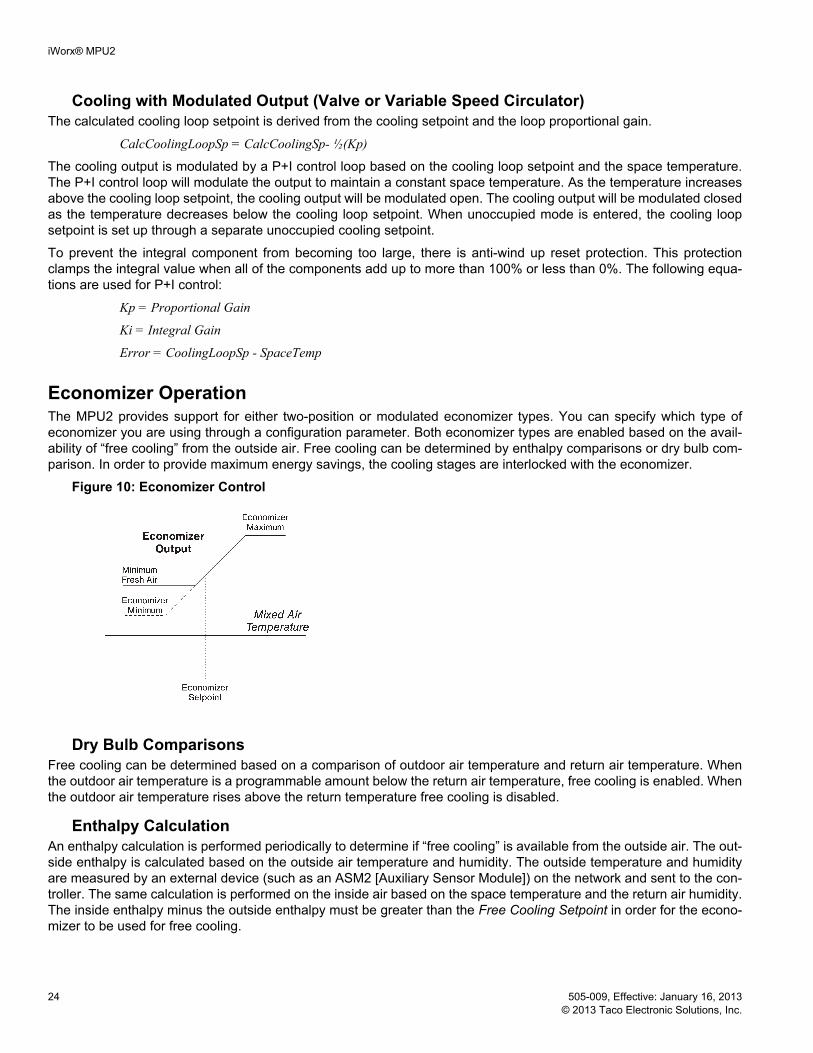
Economizer OperationThe MPU2 provides support for either two-position or modulated economizer types. You can specify which type of economizer you are using through a configuration parameter. Both economizer types are enabled based on the avail-ability of “free cooling” from the outside air. Free cooling can be determined by enthalpy comparisons or dry bulb com-parison. In order to provide maximum energy savings, the cooling stages are interlocked with the economizer.
Figure 10: Economizer Control
Dry Bulb ComparisonsFree cooling can be determined based on a comparison of outdoor air temperature and return air temperature. When the outdoor air temperature is a programmable amount below the return air temperature, free cooling is enabled. When the outdoor air temperature rises above the return temperature free cooling is disabled.
Enthalpy CalculationAn enthalpy calculation is performed periodically to determine if “free cooling” is available from the outside air. The out-side enthalpy is calculated based on the outside air temperature and humidity. The outside temperature and humidity are measured by an external device (such as an ASM2 [Auxiliary Sensor Module]) on the network and sent to the con-troller. The same calculation is performed on the inside air based on the space temperature and the return air humidity. The inside enthalpy minus the outside enthalpy must be greater than the Free Cooling Setpoint in order for the econo-mizer to be used for free cooling.

iWorx® MPU2
505-009, Effective: January 16, 2013 25 © 2013 Taco Electronic Solutions, Inc.
Optionally, an ASM2 can measure the indoor air humidity globally. In this case, the return air humidity sensor would not be required at each MPU2.
Two-position Economizer If configured, the two-position economizer is enabled when there is “free cooling” available as determined by the enthalpy or dry bulb calculations. When the economizer is enabled, the economizer triac output is energized. When the economizer is disabled, the economizer output is de-energized. A configuration parameter is available to optionally dis-able the economizer during unoccupied periods.
Modulated Economizer If configured, the modulated economizer is enabled when there is “free cooling” available as determined by the enthalpy or dry bulb calculations. When the economizer is enabled, the economizer triac output is energized. When the economizer is disabled, the economizer output is de-energized. A configuration parameter is available to optionally dis-able the economizer during unoccupied periods.
When the economizer is enabled, a Proportional + Integral (P+I) control loop modulates the economizer output position to maintain a constant mixed air temperature.
The P+I control loop is based on the mixed air temperature setpoint and economizer setpoint. As the temperature increases above the economizer setpoint, the economizer is modulated open. The economizer is modulated closed as the temperature decreases below the economizer setpoint.
To prevent the integral component from becoming too large, there is anti-wind up reset protection. This protection clamps the integral value when all of the components add up to more than 100% or less than 0%. The following equa-tions are used for P+I control:
Kp = Proportional Gain Ki = Integral Gain Error = EconSP - MixedAirTemp
When the economizer is disabled, it modulates to the minimum position. A configuration parameter is available to optionally disable the economizer during unoccupied periods.
Cutoff TemperaturesThe cutoff temperatures can be set for heating, cooling and for the economizer to suppress mechanical equipment from activating if the outside air temperature is above or below a cutoff setpoint.
Heating will be suspended when the outside air temperature rises above Max OAT Heat. It resumes when the OAT falls 5 °F below the setting. Cooling is suspended when the OAT fails below Min OAT Cool. It resumes when OAT rises 5 °F above the setting. The economizer will close the dampers to the Minimum fresh air position when the OAT is out-side the Max OAT and Min OAT Economizer temperature limits.
DehumidificationIf the Setpoint is set to zero, dehumidification is disabled. When the humidity is above the Setpoint, dehumidification begins, and it stops when the humidity drops below Setpoint minus 3%.
Dehumidification stops when the zone demand for heating is greater than the zone demand for cooling. Dehumidifica-tion is disabled when the unit is in heating.
During dehumidification, the operating mode will be displayed as “Dehumid,” the cooling outputs will stage on, and the stage timer is enforced; or, modulating output or floating point valve will be set to 100%.

iWorx® MPU2
26 505-009, Effective: January 16, 2013 © 2013 Taco Electronic Solutions, Inc.
Bypass Damper Static pressure control is achieved by modulating a bypass damper between the fully open and fully closed positions based on the measured static pressure in the supply duct. The static pressure sensor input has maximum range of 5.000" W.C. with a minimum resolution of 0.005" W.C.
The bypass damper is modulated by a P+I control loop based on the static pressure loop setpoint and the supply static pressure measurement. The P+I control loop modulates the damper to maintain a constant static pressure within the supply air duct. As the supply static pressure decreases 0.025" W.C. below the static pressure loop setpoint, the bypass damper is modulated closed. The bypass damper modulates open as the supply static pressure increases to 0.025" W.C. above the static pressure loop setpoint. When the static pressure is within ±0.025” W.C. of the static pres-sure setpoint, the damper remains at its current position.
To prevent the integral component from becoming too large, there is anti-wind up reset protection. This protection clamps the integral value when all of the components add up to more than 100% or less than 0%. The following equa-tions are used for P+I control:
Kp = Proportional Gain Ki = Integral Gain
A separate static pressure setpoint is provided to increase the supply static pressure when an IAQ alarm condition exists. The bypass damper control maintains the IAQ alarm pressure setpoint as long as an IAQ alarm condition exists.
The bypass damper modulates to the full open (bypass) position prior to the fan energizing. During operational mode changes the bypass damper remains open until the supply air temperature has reached the programmable cooling and heating setpoints. This prevents thermal shock in the zones.
Programmable minimum and maximum outputs are provided for the bypass damper. These settings can be reversed for reverse-action. Overrides are provided to assist in system air balancing during commissioning.
Analog OutputsThe modulated Economizer and Bypass Damper analog outputs support normal and reverse actuation. Making the analog output's minimum voltage scaling parameter less than the maximum enables normal actuation. Making the ana-log output's maximum scaling parameter less than the minimum enables reverse actuation.
Fan OperationDuring occupied periods, the fan may either always run or cycle off when there is no demand for heating or cooling. The fan is interlocked with the cooling and heating stages. If there is a call for heating or cooling the fan immediately energizes. During unoccupied period, the fan always cycles off when there is no demand for heating or cooling. During IAQ alarm conditions the fan energizes to provide fresh air to the zones.
Fan ProofWhen there is a call for heating or cooling, the fan output is energized. A fan status input is provided for monitoring the operation of the fan. When the fan is initially turned on, there is a 30 second delay before the fan status is checked. If at any time after the delay, the fan status indicates the fan is not running, a fan failure condition is generated. The heating and cooling stages are interlocked with the fan. When a fan failure condition exists, the heating stages, cooling stages and the fan immediately turn off. The controller must be reset to clear this condition.
NOTE: If not providing a fan proof switch, the dip switch for the fan proof input must be configured with the (0-10V) switch set to “on” and the “Vth” set to off. After a fan failure, the controller's status LED changes from green to solid red. To return the controller to normal operation after the failure condition is resolved, you must reset the controller by removing and reapplying power or by using the controller reset feature on the LCI.
Error SupplyStaticPressure LoopSetpoint–=

iWorx® MPU2
505-009, Effective: January 16, 2013 27 © 2013 Taco Electronic Solutions, Inc.
MPU2 and VAVD CommunicationsThe MPU2 and its associated VAVD controllers transfer information, depending on the number of VAVD controllers configured. The MPU2 polls a VAVD controller every 5 seconds to transfer information necessary for control. The fol-lowing information is transferred from the MPU2 to the VAVD controller:
• Operational Mode: primary cool, primary heat, and primary off• Occupancy Mode: occupied, unoccupied, and bypass• Alarm Conditions: IAQ Mode and Heat Failed On
The following information is transferred from the VAVD to the MPU2 controller:
• Zone temperature• Calculated Heating Setpoint• Calculated Cooling Setpoint• IAQ Sensor Status (safe, alarm)• Local Alarm (VAVD shutdown)• Occupancy Mode: occupied, unoccupied, and occupied extension)• Supplemental heat status: on, off
Associating VAVDsIn order for the MPU2 and VAVDs to share information, the controllers need to be associated. To associate the VAVDs to the MPU2, you first need to select the MPU2 from the LCI's list of controllers. Once the MPU2 has been selected, depress the HVAC Setup button followed by the Zone Members button. You will see a list of all VAVDs on the net-work, with the designation “Included” or “Excluded” showing on each line. To include a VAVD, simply depress the desired VAVD in the list and it will show “Included” and the color will change to Red. After all the desired associations are complete, depress the Save button so the information will be sent to all associated controllers.
Supply Air Temperature MonitoringThe MPU2 monitors the supply air temperature to determine if the heating and cooling stages are operating properly. During heating mode, if the supply air temperature does not rise above the heat mode alarm setpoint after a 10-minute delay, a heat mode alarm is generated. During cooling mode, if the supply air temperature does not drop below the cool mode alarm setpoint after a 10-minute delay, a cool mode alarm is generated.
The MPU2 has provisions for detecting a gas valve that has been become stuck in the open position. The stuck gas valve sequence helps to prevent overheating the HVAC unit.
During periods when the operational mode is primary off or primary fan only, if the supply air temperature rises above 175 °F, the system fan is started. If the supply air temperature does not drop below 150 °F after 5 minutes, the bypass damper closes and an alarm is sent to the zone controllers and LCI. The zone controllers react to the alarm by position-ing their dampers to the maximum position.
During periods when the operational mode is primary cooling, if the supply air temperature does not drop below 100 °F after 15 minutes, the cooling mode is terminated and the MPU2 enters the primary off operational mode. The primary off logic then checks for the stuck gas valve condition.
Indoor Air Quality CompensationThe MPU2 is capable of performing two modes of Indoor Air Quality Compensation. The first is to read an IAQ sensor in the return air duct and connected to the input of the MPU2. The second is to receive an IAQ alarm from one of the zone controllers.
iWorx® MPU2
28 505-009, Effective: January 16, 2013 © 2013 Taco Electronic Solutions, Inc.
The source of an indoor air quality signal connected to the MPU2 can be a digital sensor providing an on/off signal or a configurable analog sensor. Setup of the analog sensor requires the IAQ sensor settings to be populated. A Min, Max, Setpoint and an Offset can be specified. When an indoor air condition is sensed by the controller, the economizer is opened to 100%.
The MPU2 has a temperature reset function for IAQ alarm operation. The temperature reset function allows the space temperature to rise above or drop below the calculated control setpoints by a configurable amount. This feature allows time for indoor air quality to improve. During IAQ Alarm operation, if the space temperature rises above or drops below the temperature reset limit, the MPU2 will resume normal economizer control to maintain a comfort space temperature. Once the space temperature is brought within the calculated setpoints and an IAQ Alarm condition still exists, the con-troller will resume the IAQ mode of operation.
The controller has an alarm delay function that configures how long it will wait before signaling an IAQ Alarm condition.
Return Air IAQ The controller can read the status of an IAQ sensor placed in the return air duct. When the IAQ sensor indicates that contaminants are above a preset limit, the MPU2 energizes the fan. After a preset time delay, the economizer is enabled to supply fresh air to the zones. All of the zones are made aware of the IAQ alarm condition. Any zone config-ured to participate in return air IAQ modulates its damper open. Heating and cooling operate as normal.
Local Zone IAQ The MPU2 can receive the status of local IAQ sensors connected to discrete inputs of each zone controller. When the local zone IAQ sensor indicates that contaminants are above a preset limit, the MPU2 energizes the fan. After a preset time delay, the economizer is enabled to supply fresh air to the zones. Only the MPU2 and local zone controller partici-pates in local zone IAQ. Heating and cooling operate as normal.
Smoke DetectionA smoke detector input is provided. If the smoke detector indicates smoke is present, then all of the stages and the fan turn off. Once the situation has been corrected, reset the controller to clear this condition.
Mixed Air Low Limit Detection An input is provided for a mixed air low limit detection device. If a low limit condition is detected, all of the stages and the fan turns off. The controller returns to normal operation after a reset. After the controller switches from unoccupied mode to occupied mode, there is a ten minute delay before it reports Mixed air Low Limit alarms. If heating and cooling are configured as modulated or floating point, the heating valves open to 100%.
Filter StatusThe filter status input is monitored to determine if the filter is operating properly. The input is used to indicate that main-tenance is required on the filter. The controller application is not shutdown due to a filter alarm.
Real Time Clock (RTC)The RTC will be set or synced by the LCI each day at midnight. The controller will utilize the RTC in conjunction with its local backup schedule during periods when the LCI is not available.
Local Backup ScheduleThe LCI normally determines the operating mode. You can define a local backup schedule for situations when the LCI is not available. When the controller detects that the LCI is not available (after 10 minutes without communications), it resorts to the local backup schedule that has been configured. If the local backup schedule is disabled, the controller defaults to the occupied mode.

iWorx® MPU2
505-009, Effective: January 16, 2013 29 © 2013 Taco Electronic Solutions, Inc.
You configure the occupied and unoccupied times that are used in determining the current operating mode of the con-troller when it is running the backup schedule. By default, both the unoccupied and occupied times are set to zero, which disables the local backup schedule. This causes the controller to default to the occupied mode of operation when communications are lost to the LCI for 10 minutes or longer.
Runtime AccumulationsThe total runtime is accumulated for the heating, cooling, and fan outputs. The runtimes can be used to indicate that maintenance is required on the equipment controlled by these outputs. An operator or maintenance personnel can reset the runtime once servicing has been performed.
Alarms and EventsThe MPU2 detects certain alarm conditions and sends them to the LCI. Before this can occur, the MPU2 must have been configured by the LCI.
Digital Input AlarmsThe MPU2 monitors the status of the digital inputs and generates alarms for the following events:
• Fan Failure• Smoke Detect• Mixed Air Low Limit• Dirty Filter• CO2 Alarm
Supply Air Temperature AlarmsThe following alarms can be generated based on supply air monitoring.
• Cooling Failed• Heating Failed• Heat Stuck On
Maintenance AlarmA MPU2 provides programmable run limits for generating runtime maintenance alarms. When the cooling runtime, heating runtime or fan runtime exceeds these limits, a maintenance alarm is sent to the LCI.
Automatic ConfigurationThe MPU2 and iWorx® Local Control Interface (LCI) use a self-configuring network management scheme requiring no external tools, binding, or LONWORKS knowledge. The LCI recognizes and configures the MPU2 when the controller’s service pin is pressed. The controller’s status light flashes green until the controller is configured, and is solid green after the controller is configured. Once the service pin has been pressed, no further action is required by the user; the controller is fully accessible to the LCI. Users may bind to SNVTs on the MPU2 with LNS or other LONWORKS tools if they wish.
The LCI also provides network supervision of the MPU2. The LCI periodically sends a "ping" message to the MPU2, which elicits a response. If the response fails, an alarm is displayed on the LCI. The LCI also uses the "ping" message to refresh the occupancy mode and other system wide data.

iWorx® MPU2
30 505-009, Effective: January 16, 2013 © 2013 Taco Electronic Solutions, Inc.
CONTROLLER IDENTIFICATIONOnce the MPU2 is properly installed and recognized by the Local Control Interface (LCI), the LCI can be used to con-figure the settings of the controller. This section describes the commands available on the LCI for configuration of the MPU2, and the meanings and default values for controller parameters. For more information on using the LCI, see the iWorX LCI Application Guide.
InputsThe Inputs screen displays the current values of the MPU2’s inputs. These values cannot be changed.
OutputsThis screen displays the current values of the MPU2’s outputs. These values cannot be changed.
Input Range DescriptionOutside Temp -29 to 230 °F (-33.9 to 110 °C) The outside air temperature com-
municated through the LCI from the ASM controller.
Inside Enthalpy 0.0 to 60.0 BTU/lb. (0.0 to 139.6 kjoule/kg) Calculated inside air enthalpy.Outside Enthalpy 0.0 to 60.0 BTU/lb. (0.0 to 139.6 kjoule/kg) Calculated outside air enthalpy.Smoke Detector Normal, Smoke Status of the smoke detector
(SMK).Fan Status Off, On Status of the fan proof switch
(FNP)Low Limit Normal, Low Limit Status of the mixed air low limit
indication switch (MLL).Filter Status Normal, Dirty Status of the filter switch (FIL).Indoor Air Quality Normal, Alarm Status of the IAQ alarm sensor.Occupancy Mode Occupied, Unoccupied, Bypass Occupancy mode of controllerSupply Air Temp -29 to 230 °F (-33.9 to 110 °C Temperature of the supply air duct.Mixed Air Temp -29 to 230 °F (-33.9 to 110 °C) Temperature of the mixed air ple-
num.Return Air Temp -29 to 230 °F (-33.9 to 110 °C) Temperature of the return air duct.Return Air Humidity 0.00 to 100.00% Humidity reported by the RAH sen-
sor.Static Pressure 0.00 to 5.00” W.C. (0 to 1246 Pa) Static pressure in the supply air
duct.IAQ 0-4000ppm Reading of the indoor air quality
sensor when defined as Analog.
Output Range DescriptionMode Heat,
Cool, Off, Fan, Free Cooling,Dehumidification,Shut Down
Current operating mode.
Heat Output 0.00% to 100.00% Current state of the heating output.Cool Output 0.00% to 100.00% Current state of the cooling output.Economizer Output 0.00% to 100.00% Current state of the economizer
output.

iWorx® MPU2
505-009, Effective: January 16, 2013 31 © 2013 Taco Electronic Solutions, Inc.
Configuration
All SettingsDisplays all of the MPU2‘s setpoints and editable settings and provides access to edit all MPU2 parameters from a sin-gle screen.
Fan Output 0.00% or 100.00% Current state of the fan output.Bypass Damper Pos 0.00% or 100.00% Current state of the bypass output.In Alarm? On, Off Alarm indication
Setting Range Default DescriptionCommissioning Structure N/A Commissioning SettingsSetpoints Structure N/A Setpoint SettingsSupply Temp Reset Curve Structure N/A Reset SettingsPressure Settings Structure N/A Static Pressure SettingsMPU Settings Structure N/A MPU SettingsStaged Cooling Structure N/A Staged Cooling SettingsModulated Cooling Structure N/A Modulated Cooling SettingsFloating SP Cooling Structure N/A Floating Point Valve Cooling Set-
tingsStaged Heating Structure N/A Staged Heating SettingsModulated Heating Structure N/A Modulated Heating SettingsFloating SP Heating Structure N/A Floating Point Valve Heating Set-
tingsFan Type Auto, On Auto Set to “On” to enable continuous
operation during occupied mode. Otherwise, fan switches on and off automatically according to the con-trol algorithm,
Economizer Structure N/A Economizer SettingsFree Cooling Structure N/A Free Cooling SettingsDehumidification Structure N/A Dehumidification SettingsRuntime Limits Structure N/A Runtime Limit SettingsBackup Occ Time Structure N/A Backup schedule settings for
Occupied mode.Backup Unocc Time Structure N/A Backup schedule settings for
Unoccupied mode.IAQ Mode Digital, Analog Digital Type of IAQ Sensor.IAQ Settings Structure N/A Setting for the IAQ Alarm.IAQ Sensor Structure N/A Settings for the IAQ analog Sensor.OAT Cutoff Structure N/A Provides entries for cutoff tempera-
tures for heating, cooling, and economizer functions.
Output Range Description

iWorx® MPU2
32 505-009, Effective: January 16, 2013 © 2013 Taco Electronic Solutions, Inc.
CommissioningDisplays all of the commissioning settings and provides access to edit these parameters from a single screen.
SetpointsDisplays all of the setpoints and provides access to edit these parameters from a single screen.
Supply Temp Reset CurveDisplays all of the Supply Temp Reset settings and provides access to edit these parameters from a single screen.
Setting Range Default DescriptionOverride Mode Off,
Reposition Damp,Dmp Fully Open,Dmp Fully Closed
Off Set to any value besides “off” to place the controller into that over-ride mode.
Damper Percentage 0.00% to 100.00% 0.00% Damper setting to use when the controller is placed in “Damper Percentage” override mode.
Setting Range Default DescriptionCooling Setpoint 45.0 to 65.0 °F
(7.2 to 18.3 °C)55.0 °F(12.2 °C)
Temperature setpoint for the cool-ing mode.
Heating Setpoint 55.0 to 130.0 °F(12.8 to 54.4 °C)
90.0 °F(32.2 °C)
Temperature setpoint for the heat-ing mode.
Supply Cool Limit 0.0 to 30.0 °F(0.0 to 16.7 °C)
10.0 °F(5.6 °C)
Minimum temperature change from cooling setpoint in 10 minutes to avoid a cooling failed alarm.
Supply Heat Limit 0.0 to 30.0 °F(0.0 to 16.7 °C)
10.0 °F(5.6 °C)
Minimum temperature change from heating setpoint in 10 minutes to avoid a heating failed alarm.
Setting Range Default DescriptionMin Differential 0.0 to 30.0 °F
(0.0 to 16.7 °C)0.0 °F(0.0 °C)
Differential at or below which the supply air is at its coolest.
Max Differential 0.0 to 30.0 °F(0.0 to 16.7 °C)
0.0 °F(0.0 °C)
Differential at or above which the supply air is at its warmest.
Cool Setp Low 45.0 to 65.0 °F(7.2 to 18.3 °C)
45.0 °F(7.2 °C)
Lowest cooling SP when the zone is at its warmest.
Cool Setp High 45.0 to 65.0 °F(7.2 to 18.3 °C)
65.0 °F(18.3 °C)
Highest cooling SP when the zone is at its coolest.
Heat Setp Low 55.0 to 130.0 °F(12.8 to 54.4 °C)
80 °F(26.7 °C)
Lowest heating SP when the zone is at its warmest.
Heat Setp High 55.0 to 130.0 °F(12.8 to 54.4 °C)
130 °F(54.4 °C)
Highest heating SP when the zone is at its coolest.

iWorx® MPU2
505-009, Effective: January 16, 2013 33 © 2013 Taco Electronic Solutions, Inc.
Pressure SettingsDisplays all of the Static Pressure settings and provides access to edit these parameters from a single screen.
MPU SettingsDisplays all of the settings for this category and provides access to edit these parameters from a single screen.
Staged Heating/CoolingDisplays all of the settings for this category and provides access to edit these parameters from a single screen.
Setting Range Default DescriptionSetpoint -2.50” and 5.00” W.C. 1.00” W.C. Setpoint for supply air static pres-
sure.IAQ Setpoint -2.50” and 5.00” W.C. 1.50” W.C. Setpoint for supply air static pres-
sure when an IAQ alarm is present.Kp 0.00% and 100.0% 5.00% Proportional gain of the econo-
mizer’s P+I control loop.Ki 0.00% and 100.0% 0.05% Integral gain of the economizer's
P+I control loop.Minimum Output 0.0V and 10.0V 0.0V Minimum output voltage for the
Bypass Damper output.Maximum Output 0.0V and 10.0V 10.0V Maximum output voltage for the
Bypass Damper output.Press Min -2.50” and 5.00” W.C. 0.00” W.C. Static pressure to report when the
analog input receives 0 volts.Press Max -2.50” and 5.00” W.C. 2.00” W.C. Static pressure to report when the
analog input receives 10 volts.
Setting Range Default DescriptionChangeover Time 0 to 255 min 5 min Minimum amount of time between
heating and cooling.Zone Limit 0 to 32 1 Minimum number of zone demands
required before heating or cooling is enabled.
Setting Range Default DescriptionStages 0 to 2 (Heating)
0 to 4 (Cooling)2 (Heating) 4 (Cooling)
Number of heating or cooling stages controlled. Set to zero to disable staged heating or cooling.
Control Band 0 to 10.0 °F(0 to 5.56 °C)
1 °F(0.56 °C)
Value used to modify the calcu-lated heating/cooling setpoints to form the temperature range in which local heating/cooling is enabled.
Stage Time 0 to 255 minutes 5 minutes The rate at which stages are sequenced.

iWorx® MPU2
34 505-009, Effective: January 16, 2013 © 2013 Taco Electronic Solutions, Inc.
Modulated Heating/CoolingDisplays all of the settings for this category and provides access to edit these parameters from a single screen.
Floating SP Heating/CoolingDisplays all of the settings for this category and provides access to edit these parameters from a single screen.
EconomizerDisplays all of the settings for this category and provides access to edit these parameters from a single screen.
Setting Range Default DescriptionKp 0.00 to 100.00% per °F 5.00% Proportional gain of the P+I control
loop.Ki 0.00 to 100.00% 0.05% Integral gain of the P+I control
loop.Min AO Voltage 0.0 to 10.0 V 0.0 V Minimum output voltage for modu-
lation.Max AO Voltage 0.0 to 10.0 V 0.0 V Maximum output voltage for modu-
lation. If set to 0, modulation is dis-abled.
Setting Range Default DescriptionKp 0.00 to 100.00% per °F 5.00% Proportional gain of the P+I control
loop.Ki 0.00 to 100.00% 0.05% Integral gain of the P+I control
loop.Travel Time 0.0 to 600 seconds 0 seconds Total time it takes for the valve to
travel from fully closed to fully open. If set to 0 floating point is dis-abled.
Deadband 0.0 to 100.00% 10% The desired setpoint must be this far or greater from the actual posi-tion before modulating the actuator.
Setting Range Default DescriptionType Disabled,
2 St Unocc On, 2 St Unocc Off,Mod Unocc On,Mod Unocc Off
Disabled If using an economizer, set this field to a value that describes the type of economizer and whether it should be enabled during unoccu-pied periods.
Setpoint 40.00 to 70.00 °F(4.44 to 21.11 °C)
55.00 °F(12.78 °C)
Setpoint used for controlling the economizer.
Min Fresh Air 0.00 to 100.00% 10.0% Minimum fresh air position for the modulated economizer.
Kp 0.00 to 100.00% per °F 5.00% Proportional gain of the econo-mizer’s P+I control loop.
Ki 0.00 to 100.00% 0.05% Integral gain of the economizer's P+I control loop.
Min AO Voltage 0.0 to 10.0 V 0.0 V Minimum output voltage for modu-lated economizer.
Max AO Voltage 0.0 to 10.0 V 0.0 V Maximum output voltage for modu-lated economizer.

iWorx® MPU2
505-009, Effective: January 16, 2013 35 © 2013 Taco Electronic Solutions, Inc.
Free CoolingDisplays all of the settings for this category and provides access to edit these parameters from a single screen.
DehumidificationDisplays all of the settings for this category and provides access to edit these parameters from a single screen.
Runtime LimitsDisplays all of the settings for this category and provides access to edit these parameters from a single screen.
Backup Occ Time/ Backup Unocc TimeThe Backup time for Unoccupied and occupied mode is stored in the controller.
Setting Range Default DescriptionType Rtn Air Humidity,
Global Humidity,Dry Bulb Temp
Rtn Air Humidity Type of free cooling comparison to be performed.
Enthalpy Offset 0.0 to 60.0 BTU/lb(0.0 to 139.6 kjoule/kg)
5.0 BTU/lb(11.6 kjoule/kg)
Difference between inside enthalpy and outside enthalpy that enables or disables the economizer.
Dry Bulb Offset 0.0 to 20.0 °F(0.0 to 11.1 °C)
5.0 °F (2.78 °C)
Difference between return temper-ature and outside temperature that enables or disables the econo-mizer.
Setting Range Default DescriptionType Occupied,
Always enabledOccupied Defines when dehumidification is
enforced.Setpoint 0.00 to 100.00% 0% Humidity SetpointShutoff Offset 0.0 to 10.0 °F
(0.0 to 5.56 °C)2.0 °F (1.1 °C)
Heating setpoint offset to shut off dehumidification.
Setting Range Default DescriptionCooling 0 to 65,535 hours 1000 hours Runtime limit for cooling after
which a maintenance alarm is gen-erated.
Heating 0 to 65,535 hours 1000 hours Runtime limit for heating after which a maintenance alarm is gen-erated.
Fan 0 to 65,535 hours 1000 hours Runtime limit for fan after which a maintenance alarm is generated.
Setting Range Default DescriptionHours 0-23 0 Hour to start occupancy/unoccu-
pied times.Minutes 0-59 0 Minute to start occupancy/unoccu-
pied times.
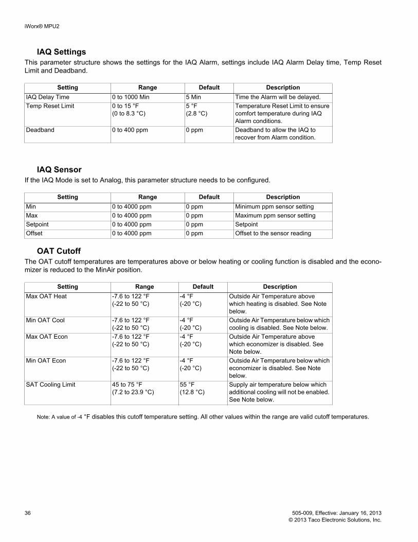
iWorx® MPU2
36 505-009, Effective: January 16, 2013 © 2013 Taco Electronic Solutions, Inc.
IAQ SettingsThis parameter structure shows the settings for the IAQ Alarm, settings include IAQ Alarm Delay time, Temp Reset Limit and Deadband.
IAQ SensorIf the IAQ Mode is set to Analog, this parameter structure needs to be configured.
OAT CutoffThe OAT cutoff temperatures are temperatures above or below heating or cooling function is disabled and the econo-mizer is reduced to the MinAir position.
Note: A value of -4 °F disables this cutoff temperature setting. All other values within the range are valid cutoff temperatures.
Setting Range Default DescriptionIAQ Delay Time 0 to 1000 Min 5 Min Time the Alarm will be delayed.Temp Reset Limit 0 to 15 °F
(0 to 8.3 °C)5 °F(2.8 °C)
Temperature Reset Limit to ensure comfort temperature during IAQ Alarm conditions.
Deadband 0 to 400 ppm 0 ppm Deadband to allow the IAQ to recover from Alarm condition.
Setting Range Default DescriptionMin 0 to 4000 ppm 0 ppm Minimum ppm sensor settingMax 0 to 4000 ppm 0 ppm Maximum ppm sensor settingSetpoint 0 to 4000 ppm 0 ppm SetpointOffset 0 to 4000 ppm 0 ppm Offset to the sensor reading
Setting Range Default DescriptionMax OAT Heat -7.6 to 122 °F
(-22 to 50 °C)-4 °F(-20 °C)
Outside Air Temperature above which heating is disabled. See Note below.
Min OAT Cool -7.6 to 122 °F (-22 to 50 °C)
-4 °F(-20 °C)
Outside Air Temperature below which cooling is disabled. See Note below.
Max OAT Econ -7.6 to 122 °F (-22 to 50 °C)
-4 °F(-20 °C)
Outside Air Temperature above which economizer is disabled. See Note below.
Min OAT Econ -7.6 to 122 °F (-22 to 50 °C)
-4 °F(-20 °C)
Outside Air Temperature below which economizer is disabled. See Note below.
SAT Cooling Limit 45 to 75 °F (7.2 to 23.9 °C)
55 °F(12.8 °C)
Supply air temperature below which additional cooling will not be enabled. See Note below.

iWorx® MPU2
505-009, Effective: January 16, 2013 37 © 2013 Taco Electronic Solutions, Inc.
AlarmsThe table below describes the alarms you may encounter and how they are reset.
TROUBLESHOOTING
Diagnostic LEDsThe controller has 3 LED indicators. These indicators can aid in troubleshooting equipment operation problems. The following table lists the functions of the controller’s LEDs in the order they appear from left to right on the unit.
Alarm Range Alarm Trigger Alarm ResetFan Failure Normal, Alarm Occurs when the fan input detects
that the fan is not running after a 30-second grace period after the fan has been activated.
The cause of the emergency condition must be resolved and the controller must be reset.
Smoke Normal, Alarm Occurs when the smoke alarm input detects the presence of smoke.
The cause of the emergency condition must be resolved and the controller must be reset.
Mixed Air Low Limit Normal, Alarm Occurs when the mixed air tem-perature drops below the Low Limit that has been set, indicating a freeze condition.
The cause of the emergency condition must be resolved and the controller must be reset.
Filter Normal, Alarm Occurs when the Filter Alarm input detects that the filter needs to be replaced.
Automatic when the dirty filter is replaced.
Indoor Air Quality Normal, Alarm Occurs when the IAQ sensor detects inadequate indoor air qual-ity.
Automatic when air quality returns within normal parameters.
Heating Failure Normal, Alarm Occurs when Supply Air tempera-ture is Supply Heat Limit degrees from the setpoint 10 minutes after entering heating mode.
The cause of the emergency condition must be resolved.
Cooling Failure Normal, Alarm Occurs when Supply Air tempera-ture is Supply Cool Limit degrees from the setpoint 10 minutes after entering cooling mode.
The cause of the emergency condition must be resolved.
Heat Stuck On Normal, Alarm Occurs when the mode is primary off or primary fan only if the supply air temperature does not drop below 150 °F after five minutes.
The cause of the emergency condition must be resolved.
Maintenance Normal, Alarm Occurs when the fan, heating, or cooling operating hours have exceeded their Runtime limit.
To clear the alarm, a user must enter a new value for the alarm limit or reset the accumulated times to zero.

iWorx® MPU2
38 505-009, Effective: January 16, 2013 © 2013 Taco Electronic Solutions, Inc.
Figure 11: MPU2 Controller LEDs
Status Network Service
Troubleshooting TipsThis section provides remedies for common problems.
LED IndicationStatus – Solid green when running and configured by an LCI (networking)
– Flashing green when running and NOT configured by an LCI (stand-alone)– Solid red when a fault condition exists (control shut down)– Blinking Red - the controller has a device failure– Solid Amber - The controller has not received a LCI ping message in over 10 minutes and is part of a network.
Network – Yellow while the controller is transmitting data onto the FTT-10A network – Green when there is network activity– Off when there is no network activity
Service – Illuminated when the service pin is depressed or when a controller gets configured by the LCI.
Problem SolutionController is not running and Status LED is not illuminated.
No power to controller. Verify the voltage on the controller’s power connector (24 VAC).
How do I reset the controller? The controller can be reset by the LCI, or you can cycle power to the controller. Refer to the LCI documentation for more infor-mation on resetting the controller using the LCI.
Can my iWorx® system contain multiple MPU2 controllers?
Yes, provided that you do not exceed the maximum number of controllers that can be handled by the Local Control Interface (LCI).

iWorx® MPU2
505-009, Effective: January 16, 2013 39 © 2013 Taco Electronic Solutions, Inc.
Getting HelpComponents within an iWorx® controller, sensor, or power supply cannot be field repaired. If there is a problem with a unit, follow the steps below before contacting your local TES representative or TES technical service.
1.Make sure controllers, sensors, and power supplies are connected and communicating to desired devices.2.Record precise hardware setup indicating the following:
Version numbers of applications software.
Controller firmware version number.
A complete description of difficulties encountered.
Notes:
Can I reverse the minimum and maximum val-ues for the bypass damper?
Yes. This will result in reverse damper action.
Can I use the bypass damper outputs to control a VFD instead?
Yes.
Thermistor readings fluctuate rapidly, some-times by several degrees.
The controller is not properly grounded. The controller’s ground (GND) pin (T40) must be connected to earth ground.
Problem Solution
iWorx® MPU2
Printed in the USA iWorx® and iView® are registered trademarks of Taco Electronic Solutions, Inc. © 2013 Taco Electronic Solutions, Inc. LON, LONWORKS, & LONMARK are trademarks of Echelon Corporation
CONTROLS MADE EASY®
Taco Electronic Solutions, Inc., 1160 Cranston Street, Cranston, RI 02920 Telephone: (401) 942-8000 FAX: (401) 942-2360.
Taco (Canada), Ltd., 8450 Lawson Road, Unit #3, Milton, Ontario L9T 0J8. Telephone: 905/564-9422. FAX: 905/564-9436.
Taco Electronic Solutions, Inc. is a subsidiary of Taco, Inc. Visit our web site at: http://www.taco-hvac.com
Taco Electronic Solutions, Inc. (TES) will repair or replace without charge (at the company's option) any product or part which is proven defective under normal use within one (1) year from the date of start-up or one (1) year and six (6) months from date of shipment (whichever occurs first).
In order to obtain service under this warranty, it is the responsibility of the purchaser to promptly notify the local TES stocking distribu-tor or TES in writing and promptly deliver the subject product or part, delivery prepaid, to the stocking distributor. For assistance on war-ranty returns, the purchaser may either contact the local TES stocking distributor or TES. If the subject product or part contains no defect as covered in this warranty, the purchaser will be billed for parts and labor charges in effect at time of factory examination and repair.
Any TES product or part not installed or oper-ated in conformity with TES instructions or which has been subject to accident, disaster, neglect, misuse, misapplication, inadequate operating environment, repair, attempted repair, modification or alteration, or other abuse, will not be covered by this warranty.
TES products are not intended for use to sup-port fire suppression systems, life support sys-tems, critical care applications, commercial aviation, nuclear facilities or any other applica-tions where product failure could lead to injury to person, loss of life, or catastrophic property damage and should not be sold for such pur-poses.
If in doubt as to whether a particular product is suitable for use with a TES product or part, or for any application restrictions, consult the applicable TES instruction sheets or in the U.S. contact TES at 401-942-8000 and in Canada contact Taco (Canada) Limited at 905-564-9422.
TES reserves the right to provide replacement products and parts which are substantially simi-lar in design and functionally equivalent to the defective product or part. TES reserves the right to make changes in details of design, con-struction, or arrangement of materials of its products without notification.
TES OFFERS THIS WARRANTY IN LIEU OF ALL OTHER EXPRESS WARRANTIES. ANY WARRANTY IMPLIED BY LAW INCLUDING
WARRANTIES OF MERCHANTABILITY OR FITNESS IS IN EFFECT ONLY FOR THE DURATION OF THE EXPRESS WARRANTY SET FORTH IN THE FIRST PARAGRAPH ABOVE.
THE ABOVE WARRANTIES ARE IN LIEU OF ALL OTHER WARRANTIES, EXPRESS OR STATUTORY, OR ANY OTHER WARRANTY OBLIGATION ON THE PART OF TES.
TES WILL NOT BE LIABLE FOR ANY SPE-CIAL, INCIDENTAL, INDIRECT OR CONSE-QUENTIAL DAMAGES RESULTING FROM THE USE OF ITS PRODUCTS OR ANY INCI-DENTAL COSTS OF REMOVING OR REPLACING DEFECTIVE PRODUCTS.
This warranty gives the purchaser specific rights, and the purchaser may have other rights which vary from state to state. Some states do not allow limitations on how long an implied warranty lasts or on the exclusion of incidental or consequential damages, so these limitations or exclusions may not apply to you.
LIMITED WARRANTY STATEMENT