self healing concrete a sustainable future - · pdf fileself healing concrete – a...
TRANSCRIPT

Self Healing Concrete – A Sustainable Future
Simon Dunn, BEng (hons), Cardiff University
Abstract The cement industry is a major global contributor to world CO2 emissions (8% in 2008). A major
cause of this high percentage is the durability issues associated with concrete. In recent years a new
breed on concrete that has the ability to heal cracks which are a major cause of these durability
issue has been developed called Self-healing Concrete. This paper will introduce this new breed of
concrete in its various forms, with particular attention paid to the form which incorporates shape
memory polymers as the healing mechanism. The shape memory polymer-cementitious composite
has been developed at Cardiff University and is the subject of a patent pending. The paper will focus
on the experimental and numerical work undertaken to understand the material behaviour of shape
memory polymers and how this can be applied to the cementitious composite. A numerical model
has been developed and the successful comparison to experimental data will be presented
1. Introduction The environmental impact of the cement industry is an ever increasing concern for engineers, with
the cement industry generating approximately 8% of all the world CO2 emissions (2008 figures) (1)
up from 5% in 2001 (2).When compared to the aviation industry which contributes 2% of world CO2
emissions (3), it is clear as engineers we have a major part to play in protecting future generations
from global warming. In addition to the environmental impact of the cement industry, the economic
impact is also a major issue. Approximately half of the £80x109 spent on construction work in the UK
per annum is allocated to repair and maintenance of existing structures, many of which are concrete
structures (4). A more durable cementitious material will allow less maintenance and a longer
working life, reducing the amount of cement required and thus the environmental and economic
impact.
The durability of concrete is compromised by the ingress of harmful chemicals such as saline water,
CO2 and acid rain into cracks created during early age shrinkage and/or mechanical loading. The
current practice is to overdesign the structure in order to achieve a maximum crack width between
0.1 and 0.4mm under long term serviceability loading (5). A commonly used solution is to make use
of pre-stress by pre or post-tensioning. These pre-stressed structures are designed to be uncracked
during serviceability loading, although in recent times there have been problems with the durability
of such structures. The major problem with the pre-stressed system is that steel tendons are
relatively expensive and require expensive anchors and jacking operations, which themselves also
pose a health and safety issue.
There have been many recent developments in the production of more durable concrete, namely
that of self-healing concrete. Despite its relative infancy, it provides a valid and practical solution to
the problem.

This paper will introduce self-healing concrete in its various forms and particular attention will be
paid to the solution being developed at Cardiff University which utilises shape memory polymers (6).
The main focus of this paper will be the determination and subsequent numerical simulation of a
suitable shape memory polymer. Experimental data and comparisons with numerical data will be
presented. The main aims of this research have been to:
(1) Determine a suitable shape memory polymer,
(2) Understand the behaviour of the chosen material,
(3) Produce a successful numerical model, validated by experimental data.
2. Self Healing of Cementitious Composites The development of self-healing cementitious composites is a relatively new area of research which
to this date has focused both on the natural ability of hydrates to heal cracks over time (autogenic)
and artificial means of crack repair that are man-made inclusions (autonomic) (7). The motivation for
such work is to increase the durability of concrete.
The natural self healing ability of concrete, known as autogenous healing, has been understood for
around 20 years (8). The effect can be seen in many old structures which have survived for such long
periods of time with only limited maintenance. Cracks in old concrete structures such as Roman
aqueducts and gothic churches have been seen to heal when moisture interacts with unhydrated
cement clinker in the crack. However in recent structures the cement content is reduced due to
modern construction methods and hence the amount of available unhydrated cement is lower (9)
and the natural healing effect is reduced. The three main processes of autogenous healing according
to Joseph (10) are (i) swelling and hydration of cement pastes; (ii) precipitation of calcium carbonate
crystals, and; (iii) blockage of flow paths due to deposition of water impurities or movement of
concrete fragments that detach during the cracking process. Numerous authors in recent years have
investigated various situations that affect the amount and rate of autogenic healing including the
effect of temperature (11), degree of damage (12), freeze-thaw cycles (13) and the age of the
concrete (14). The mix composition of the mortar can also be used to enhance the autogenic
behaviour, for example by including blast furnace slag into the mix (9). It was found that maximum
healing occurred in early age concrete (15) and specimens tested under water showed the best
strength recovery, hence it was concluded that the primary healing mechanism was ongoing
hydration.
The man-made self healing ability of concrete, known as autonomic healing was first introduced by
Dry in 1994 (16). The system proposed by Dry was similar to that used in polymers in which a healing
agent is encapsulated inside a microcapsule and when a crack forms it breaks the microcapsule,
releasing the healing agent and healing the crack. There are two main aspects to consider with
regard to the autonomic healing concept, namely, the encapsulation method and the healing agent
that is encapsulated.
There have been a number of healing agents proposed, however these are generally ‘off the shelf’
agents, making them relatively low cost and readily available. This suits the nature of their use in
large bulk material such as concrete (10). To date the most common healing agents proposed are
epoxy resins, cyanacrylatates, and alkali-silica solutions. Joseph states that there are a number of

pre-requisites that an agent must possess including, a suitably low viscosity to ensure a wider repair
area and a sufficiently strong bond between crack surfaces and that there should be adequate
capillary forces to draw the agent into the crack. A system developed by Nishiwaki et al (17) stores a
low viscosity epoxy resin in an organic film pipe that melts at 93°C. Upon formation of a crack,
sensed via a strain gauge, there is a reduction in electrical conductivity and hence increased
resistance and temperature. This increased temperature melts the organic supply tube and cures the
epoxy resin after it has flowed into the crack. Cyanoacrylates, commonly known as super glues, are
one part systems that in the presence of moisture react and cure very rapidly forming a bond often
stronger than the material it is bonding, i.e. concrete. Hence the healed crack is actually stronger
than the surrounding material itself. This system has been rigorously tested and developed by
Joseph (10) who showed that if a system is damaged and healed and then damaged again, a new
crack will form around the healed crack. The use of cyanoacrylates in concrete is further enhanced
by them being an acidic solution which due to the concretes alkaline environment causes yet quicker
healing. Finally, alkali-silica solutions have also been utilized as healing agents mainly by Mihashi et
al. (18) who state that in the presence of oxygen the solution causes hydration and hence bonding of
the original crack faces. Although this system produces a lower bond strength, it causes less material
compatibility problems than the previous two systems.
The previously described healing agents require a method to encapsulate them in the cementitious
matrix until they are required for healing. Several methods have been proposed including the use of
micro-capsules, a continuous glass supply tube (18) and capillary tubes (19) which are embedded in
the concrete. Microcapsules have the advantage that the concrete can react to diffused cracking in
multiple locations, although once a capsule has “been utilized” it cannot be refilled and it remains a
void in the concrete. Capillary tubes used in the medical profession for blood testing have been
embedded in concrete as encapsulating vessels for ethyl cyanoacrylate healing agent. Experiments
showed that despite some localized debonding between the tube and cement matrix, the system
was successful in sensing crack propagation and actuating accordingly healing the crack (19). Finally,
continuous glass supply pipes which have the advantage of being able to vary the healing agent and
supply additional healing agent have proven successful in healing larger fractures (18). The issue
with such a system however is that care must be taken in placing the glass tubes and hence is not
suitable for cast in-situ concrete.
One further and very interesting method of producing self-healing concrete is being developed at
DELFT University in The Netherlands which makes use of mineral producing bacteria. In this system
the bacteria act as a catalyst and transform a precursor compound into a suitable filler material,
such as calcium carbonate based mineral precipitates. The filler material then acts as a type of bio-
cement which effectively seals newly formed cracks (20).
The proposed system being developed at Cardiff University combines both the autogenic healing
and autonomic principles in that it makes use of a man-made system to enhance the natural
autogenic healing and repair cracks in concrete. The system incorporates shape memory polymers
into the cementitious matrix to place the crack in the most favourable conditions for autogenous
healing to occur.

3. Proposed Cementitious-Shape Memory Polymer Composite The proposed cementitious-shape memory polymer composite system being developed at Cardiff
University is the subject of a previous paper (21) and has a patent pending (22). The aim of the
system is to improve the durability of cementitious materials by incorporating a mechanism for crack
closure into the cementitious matrix. The self repairing of cracks will prevent the ingress of harmful
chemicals such as saline water, acid rain and CO2, all of which reduce the working life of concrete
structures.
Shape memory polymers are semi-crystalline polymers which have a predefined shape memorised in
their material structure. In the case of the proposed system the memorised state is a shorter
specimen than the current material, so that upon activation the specimen will contract or shrink and
in a restrained condition generate a shrinkage force (23).
Figure 1: Proposed shape-memory polymer-cementitious composite
Upon crack formation the system seen in Figure 1 will be triggered. The shape memory polymer,
which is anchored within a cavity in the cementitious matrix is activated via heating. Heating can be
in the form of direct heat or electrical current via an increase in temperature due to high ohmic
resistance. Upon activation the shape memory effect or shrinkage occurs and due to the restrained
nature of the tendon, a tensile force is generated. This tensile force in turn imparts a compressive
force to the cementitious matrix at the crack location and hence the crack closes. Autogenous
healing then occurs and is enhanced by the crack being put into this compressive state (15). Studies
into further enhancing this autogenous healing have also been carried out and this is the subject of a
forthcoming publication (24).
3.1. Material Screening Study In order to determine a suitable material for the proposed system a pilot study was undertaken (25).
The suitable material must be capable of developing a shrinkage stress of 20MPa following
activation in a restrained condition. The activation may be initiated by heat applied directly or via an
electrical current. The temperature of stress development must occur between 70-90°C to prevent
premature activation during the hydration process of the cementitious material or damage to
surrounding concrete. Future considerations include that the material should also be inert to
alkaline environment and maintain >70% of the shrinkage stress for the working life of the structure
(6). The screening tests highlighted Aerovac Shrinktite, a drawn polyethylene terephthalate (PET)
polymer material, manufactured in 32x0.046mm tapes as best suiting the criteria.

3.2. Experimental Simulation of Shape Memory Polymer A series of experiments were carried out on the chosen PET material to determine both the material
properties and shrinkage effects with temperature. Reference (26) provides a detailed summary of
further experimental work.
3.2.1. Specimen Preparation and Testing Procedure
Specimen preparation was required to enable a suitable and accurate test procedure. The testing
procedure and preparation was the result of a series of preliminary investigations to ensure an
accurate and reliable data set. In order to minimise slippage of the specimens when gripped the PET
tapes were manufactured into a collection of 25 strips each measuring 6mm x 0.046mm x 450mm in
length, bonded at either end using a soldering iron and specially designed jig (26). Two steel plates
(10x20x3mm) were then placed at a distance of 360mm apart and centrally on the specimen. The
remaining length of polymer was then melted to create a mechanical plug, which serves as a
mechanical lock preventing slippage, as seen in Figure 2(b).
The specimens were then loaded into grips in a Dartec tensile testing machine fitted with an Instron
environmental chamber capable of temperatures ranging from -50°C to +250°C as seen in Figure
2(a). A pre-load of 50N was applied to remove any slack.
Figure 2: Experimental Set-up, (a) Thermal Chamber and (b) Specimen
Two parametric studies were then undertaken to investigate the development of shrinkage with
temperature and the development of the Young’s modulus with temperature.
3.2.2. Development of Shrinkage Stress with Temperature
The specimen was held at constant displacement while the stress, time and temperature was
monitored as the temperature was raised rapidly to 90°C and soaked for 3 hours before returning
5kN Load Cell
Grip
PET Specimen
Instron
Environmental
Chamber
Grip
Dartec Tensile Testing Machine
360mm
20mm
Mechanical
Lock Steel Plates (10x20x3mm)
Steel Plates (10x20x3mm)
No. 25, 6mm wide PET Strips

the temperature to ambient and soaking for a further 1 hour. Plots of stress development with both
temperature and time were achieved and can be seen in Figures 3a and 3b respectively.
Figure 3: Stress Development with (a) Temperature and (b) Time
The results show that a shrinkage stress of 32.5MPa is achieved following the 3 hour soak at 90°C.
The generation of this shrinkage stress is a known property of drawn shape memory polymers such
as PET, whose molecules are stretched into a more random configuration during the drawing
process. The effect of heating is to release these molecules which tend toward their favourable
coiled conformation due to entropic considerations. In their restrained condition the molecules
cannot retract and therefore generate a shrinkage force as the entropic forces balance with the
external constraint. As the molecules enter a state of tension it is known that their ability for
shrinkage is reduced and hence the stress plateau (27). The subsequent rise in stress following the
return to ambient is the result of two effects: the thermal contraction of the steel equipment in the
thermal chamber and the thermal contraction of the polymer. The thermal contraction of the
polymer before and after the temperature soak can be seen to vary (slope of the stress-temperature
graph) which is consistent with the observations of Bhushan (28) who proposed that the coefficient
of thermal expansion increases slightly following annealing (heating above the transition
temperature, 75°C).
3.2.3. Development of Young’s Modulus with Temperature
The specimen was held at constant load while the temperature was raised in 10°C increments from
30°C to 160°C while the displacement, temperature and time were recorded. At each temperature
increment the specimen was soaked for 5 minutes before increasing the load by 10N at a chosen
rate, three rates were investigated: 10N/s, 1N/s and 0.1N/s. The load was then decreased by 10N at
the chosen rate monitoring the stress, strain and time at a frequency of 100Hz during both the
loading and unloading. The loading and unloading cycle is referred to as an “E-Value” test and is
repeated at every temperature increment. A graph of Young’s modulus with temperature can be
seen in Figure 4.

Figure 4: Young ’s Modulus with Temperature
The graphs show a clear relationship between the Young’s modulus and temperature. Prior to 70°C
(known as the glass transition temperature) the Young’s modulus is constant at approximately
6000MPa. Following the glass transition temperature a transition of an exponential form was
observed prior to the lower plateau of approximately 1000MPa at 120°C. These observations are
consistent with those of Tobushi et al (29). The trend is the same for the different loading rates,
however the faster loading rates have a slightly higher value throughout indicating that the Young’s
modulus is rate dependent to a certain degree.
3.2.4. Conclusions
The experimental studies have highlighted Aerovac Shrinktite, as a suitable polymer for the
proposed system. The material generates a shrinkage stress of 32.5MPa at 90°C which is a suitable
temperature and stress for applications involving concrete. Furthermore, a clear relationship
between the Young’s modulus and temperature has been found and will be required in the
development of a numerical model for the polymer.
3.3. Numerical Simulation of Shape Memory Polymer Existing numerical models for the simulation of temperature dependent shrinkage processes in PET
were investigated in order to develop the subsequent numerical model. Pioneering work by Henry
Eyring in the 1940s marked the start of such models and formulated that the deformation behaviour
of polymers was a thermally activated rate process involving the motion of segments of chain
molecules over potential barriers (30). Eyring proposed that a temperature dependant dashpot
replace the existing dashpot in the Standard Linear Model. This model represents non-linear
viscoelastic behaviour and is related to physical parameters in that it requires the input of an
activation volume and activation energy.

Based on the principles proposed by Eyring, but taking a different approach was the work initially
carried out by Trznadel (31) and progressed by Morshedian (32). They proposed a four-state model
that qualitatively describes the temperature dependence of polymers. The model is characterized by
two elastic springs and two two-site elements. It is the two-site elements that make the model
unique and they are described as modelling the local properties of a molecular subunit and its
interactions with the matrix. The two two-site elements have 4 possible configurations each relating
to different conditions of deformation behaviour of the polymer.
Tobushi et al (33) proposed that the isothermal mechanical behaviour of polymers can be described
by a four element rheological model consisting of an elastic spring and viscous dashpot in parallel
with a friction element and another viscous dashpot. It is the friction element that models the effect
of shape memory strain. Tobushi also proposed, in a later paper (29), that the material parameters
(Modulus of elasticity, viscosity, retardation time and coefficient of thermal expansion) should be
expressed by an exponential function of temperature.
The model on which Eyring is based; the basic Standard Linear Solid (SLS) model; is usually attributed
to Zener (34). The SLS model consists of an elastic spring in parallel with a Maxwell unit (spring and
dashpot in series) and gives a good approximation of observed behaviour of polymers in their
viscoelastic range. The model describes both creep and stress relaxation in addition to the transition
from a glassy (short term) modulus to the rubbery (long term) modulus. However this SLS model fails
to include the effect of temperature and shrinkage on the deformation behaviour of polymers.
The proposed numerical model has been developed through consideration of the above mentioned
existing models and the methods they employ along with the observations made in the experimental
studies. The model aims to simulate the stress-strain-temperature-time behaviour of PET in a 1D
uniaxial form.
3.3.1. Proposed Constitutive Model
A rheological representation of the proposed model can be seen in Figure 5 and consists of an elastic
spring (E1) in parallel with a temperature dependant elastic spring (E2) and a temperature dependant
viscous dashpot (η).
Figure 5: Rheological Representation of Proposed Model
E1
η(T)
E2(T)
σ
σ
ε1
εve
ε
σ2 σ1
σ = Applied Stress
ε = Applied Stain

The general stress conditions of the model are given by:
[1]
[2a]
[2b]
A time stepping process is used to obtain the solution of equations (1) and (2) in terms of the
temperature dependant relaxation time (τfunc) and the previous viscous strain.
[3]
An intermediate value of strain, is used and is taken as 0.5. The current time step (j) is used
along with the previous time step (j-1), while the temperature dependent relaxation time is given in
equation (4):
𝜏𝑓𝑢𝑛𝑐 𝑇 =𝜂 (𝑇)
𝐸2(𝑇) [4]
The temperature dependant viscosity is given by:
[5]
In which and
The key temperatures used in the model are the current temperature (T), the temperature at the
centre of the transition (Tg) and the limiting temperatures TH and TL which can be seen in Figure 6
below. Figure 6 also highlights the values of E1 and Etot which are experimentally derived from the
10N/s E-value tests. The constants b, c, d and f are fitting parameters.
Figure 6: Idealised Young ’s Modulus with Temperature
E1
Etot
Elas
tic
Mo
du
lus
TH Temperature TL
Experimentally derived viscosities at the higher (i.e. melted) and lower (i.e. solid) temperatures are
given by and respectively.
The elastic modulus, E2 is also temperature dependant where:
[8]
[9]
Equations (1), (2a) and (2b) are used to derive an equation for the stress in the system
[10]
Equation (10) highlights the constitutive behaviour for the polymer PET and also incorporates the
coefficient of thermal expansion, . This takes into account the effect of thermal expansion on the
total strain, which is significant prior to the onset of shrinkage. Investigations into the effect of
shrinkage on the coefficient of thermal expansion are not considered here and are the subject of
future work.
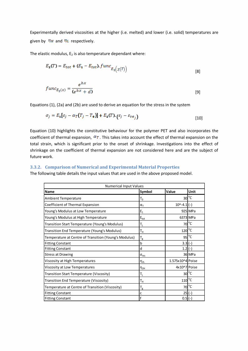
3.3.2. Comparison of Numerical and Experimental Material Properties
The following table details the input values that are used in the above proposed model.
Name Symbol Value Unit
Ambient Temperature T0 30oC
Coefficient of Thermal Expansion αT 10^-4.1 (-)
Young's Modulus at Low Temperature E1 925 MPa
Young's Modulus at High Temperature Etot 6373 MPa
Transition Start Temperature (Young's Modulus) TL 70oC
Transition End Temperature (Young's Modulus) TH 120oC
Temperature at Centre of Transition (Young's Modulus) Tg 95oC
Fitting Constant b 3.3 (-)
Fitting Constant d 1.2 (-)
Stress at Drawing σres 36 MPa
Viscosity at High Temperatures η2L 1.575x10^4 Poise
Viscosity at Low Temperatures η2H 4x10^7 Poise
Transition Start Temperature (Viscosity) TL 30oC
Transition End Temperature (Viscosity) TH 110oC
Temperature at Centre of Transition (Viscosity) Tg 70oC
Fitting Constant c 25 (-)
Fitting Constant f 0.5 (-)
Numerical Input Values

The faster loading rate results (10N/s) were used to determine values for the E2 component as the
faster rate ensures that no viscous effects occur during the experiment and that the results are
purely elastic. Figure 7(a) compares the experimentally derived results with the numerically derived
results that are the produced using equation (8). The comparison shows a very good agreement.
Figure 7: Comparison of Numerical and Experimentally Derived Material
Properties, (a) Young ’s Modulus and (b) Viscosity
The viscosity variation with temperature is derived using a backward calculation from the slower and
faster loading rate E-value tests. The slower rate will incorporate the viscous effects whereas the
faster rate is purely elastic. An apparent Young’s modulus is defined:
[11]
The change in viscous strain is then determined using equations (1) and (11) in which E1 and Etot are
defined in Figure 6, E2 values are taken from Figure 7a and Eapp is the apparent Young’s modulus
determined from the slower (0.1N/s) loading rate which includes the viscous component:
[12]
Equations (12) and (3) are then compared neglecting the array formulations in equation (3) and
rearranged to yield for a time t=Δt the expression for the experimentally determined viscosity:
[13]
Figure 7(b) compares the experimentally derived viscosity with the viscosity derived numerically in
equation (6) and show excellent agreement.
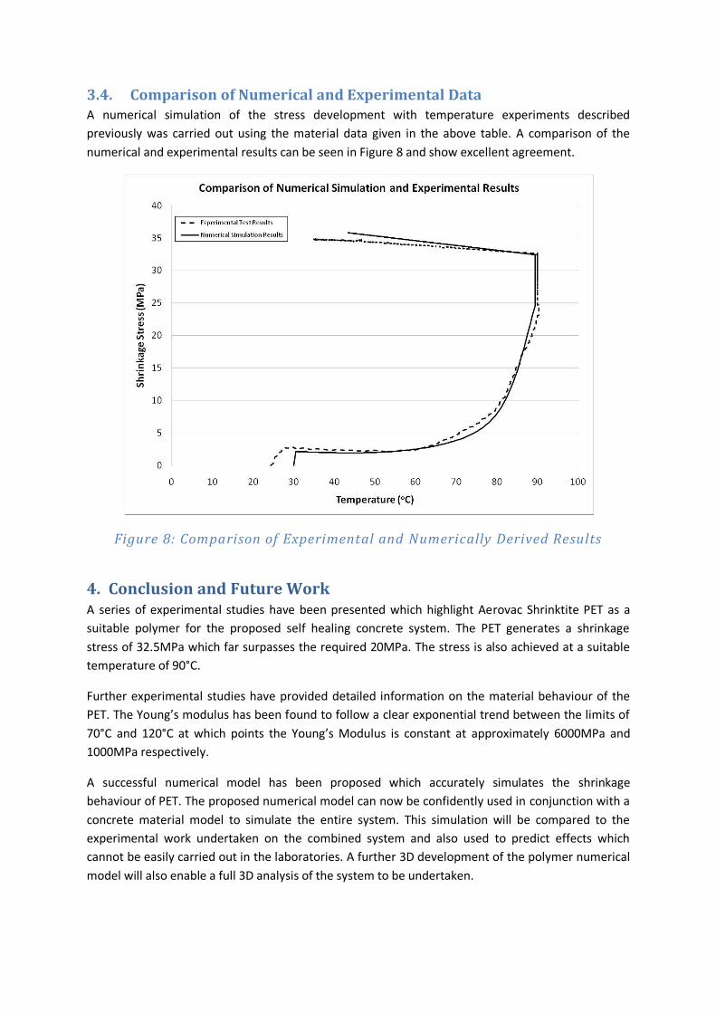
3.4. Comparison of Numerical and Experimental Data A numerical simulation of the stress development with temperature experiments described
previously was carried out using the material data given in the above table. A comparison of the
numerical and experimental results can be seen in Figure 8 and show excellent agreement.
Figure 8: Comparison of Experimental and Numerically Derived Results
4. Conclusion and Future Work A series of experimental studies have been presented which highlight Aerovac Shrinktite PET as a
suitable polymer for the proposed self healing concrete system. The PET generates a shrinkage
stress of 32.5MPa which far surpasses the required 20MPa. The stress is also achieved at a suitable
temperature of 90°C.
Further experimental studies have provided detailed information on the material behaviour of the
PET. The Young’s modulus has been found to follow a clear exponential trend between the limits of
70°C and 120°C at which points the Young’s Modulus is constant at approximately 6000MPa and
1000MPa respectively.
A successful numerical model has been proposed which accurately simulates the shrinkage
behaviour of PET. The proposed numerical model can now be confidently used in conjunction with a
concrete material model to simulate the entire system. This simulation will be compared to the
experimental work undertaken on the combined system and also used to predict effects which
cannot be easily carried out in the laboratories. A further 3D development of the polymer numerical
model will also enable a full 3D analysis of the system to be undertaken.

Acknowledgements The author would like to acknowledge Prof. Lark, Dr Jefferson, Dr Joseph and Ben Isaacs of Cardiff
University for their participation in the development of the new cementitious-shape memory
polymer composite.
Bibliography 1. Energy efficient cement could radically cut emissions. www.energyefficiencynews.com. [Online]
[Cited: 20 December 2009.] http://www.energyefficiencynews.com/i/1665/.
2. Worrell, E, et al. 2001, Annual Review of Energy and Environment, 2001, Vol. 26.
3. IATA. 2009, Aviation Environment. www.iata.org. [Online] [Cited: 20 December 2009.]
http://www.iata.org/whatwedo/environment/climate_change.htm.
4. DTI. 2006, Construction statistics annual report 2006. London : TSO.
5. Eurocode 2: Design of concrete structures - Part 1-1: General rules and rules for buildings. EN1992-
1-1. 2004.
6. Lark, R L, et al. 2010, Cement and Concrete Research, Accepted January 2010
7. RILEM. 2009, STAR - Self Healing Materials (DRAFT). : RILEM.
8. Schlangen, E. 2005, Self-healing phenomena in cement-based materials. RILEM. [Online]
http://www.rilem.org/tc_shc.php.
9. van Tittelboom, K and De Belie, N. 2009, 2nd International Conference on Self Healing Materials,
Chicago.
10. Joseph, C. 2008, Experimental and Numerical Study of the Fracture and Self-Healing of
Cementitious Materials - PhD Thesis. : Cardiff University.
11. Reinhardt, H-W and Loos, M. 2003, Cement and Concrete Research 33, pp. 981-985.
12. Zhong, S and Yao, W. 2008, Construction and Building Materials 22(6), pp. 1137-1142.
13. Jacobsen, S and Sellevold, E J. 1996, Cement and Concrete Research, 26(1), pp. 55-62.
14. Edvardsen, C. 1999, ACI Materials Journal, 96(4), pp. 448-454.
15. Ter Heide, N, Schlangen, E and van Breugel, K. 2005, Knud Hoejgaard Conference on Advanced
Cement-Based Materials, Technical University of Denmark
16. Dry, C M. 1994, Smart Materials and Structures, 3(2), pp. 118-123.
17. Nishiwaki, T, et al. 2006, Journal of Advanced Concrete Technology, 4(2), pp. 267-275.
18. Mihashi, H, et al. 2000, Transactions of the Japan Cement Institute 22, pp. 441-450.
19. Li, V C, Yun Mook, L and Yin-Wen, C. 1998, Composites Part B: Engineering, 29(6), pp. 819-827.

20. Jonkers, H M and Schlangen, E. 2009, 2nd International Conference on Self-healing Materials,
Chicago.
21. Lark, R L, et al. 2009, Cement and Concrete Research, (Submitted).
22. Jefferson, A D, Lark, R L and Joseph, C. 2007, GB0715123 Great Britain/Wales.
23. Dunn, S C, et al. 2009, 2nd International Conference for Self-healing Materials, Chicago.
24. Isaacs, B, et al. 2010, Cement and Concrete Research, (In Progress).
25. Lark, R J, et al. 2009, 2nd International Conference of Self-Healing Materials, Chicago.
26.Dunn, S C, et al. 2010, Polymer (Submitted).
27. Gupta, V B, Radhakrishnan, J and Sett, S K. 1994, Polymer 12, Vol. 35.
28. Bhushan, Bharat. 2000, Mechanics and reliability of flexible magnetic media - 2nd Edition. New
York : Springer-Verlag.
29. Tobushi, H, et al. 2001, Mech. Mat. 33, p. 545.
30. Halsey, G, White, H J and Eyring, H. 1945, Textiles Research Journal 15, p. 295.
31. Pakula, T and Trznadel, M. 1985, Polymer 26, p. 1011.
32. Morshedian, J, Khonakdar, H A and Rasouli, S. 2005, Macromol Theory Simul 14 , p. 428.
33. Bhattacharyya, A and Tobushi, H. 2000, Poly. Engin. Sci. 40, p. 2498.
34. Zener, C. 1948, Elasticity and Anelasticity of Metals. Chicago : Chicago University Press.