self-induced oscillations in electronically-coupled...
TRANSCRIPT

Self-Induced Oscillations inElectronically-Coupled Fluxgate Magnetometers
Visarath In∗, Adi Bulsara∗, Andy Kho∗, Antonio Palacios†, PatrickLonghini†, Juan Acebron∗∗, Salvatore Aglio‡ and Bruno Ando‡
∗Space and Naval Warfare Systems Center, Code 2363, 53560 Hull Street, San DIego, CA92152-5001, USA
†Nonlinear Dynamics Group, Department of Mathematics and Statistics, San Diego StateUniversity, San Diego, CA 92182-7720, USA
∗∗Dipartimento di Ingegneria dell’ Informazione, Universita’ di Padova, Via Gradenigo 6/B,35131 Padova, ITALY
‡Dipartimento di Ingegneria Elettrica Elettronica e dei Sistemi, Univ. degli Studi di Catania, VialeA. Doria 6, 95125 Catania, ITALY.
Abstract. We present theoretical and experimental investigations of the fundamental idea thatcoupling-induced oscillations can enhance the sensitivity of an array of magnetic sensors. In par-ticular, we consider arrays made up of fluxgate magnetometers inductively coupled through elec-tronic circuits. The underlying dynamics of the coupled system is more complicated as it showsnew spatio-temporal features that are not observed in a single fluxgate. Among these new features,self-induced oscillations in the form of a traveling wave pattern are of particular interest becausethey can lead to higher sensitivity levels at reduced costs. Details of the experiments, a new signaldetection mechanism, and results from numerical bifurcation analyzes are described in this work.
INTRODUCTION
Fluxgate magnetometers are considered to be the most cost-efficient magnetic fieldsensors for applications that require measuring relatively small magnetic fields. Forinstance, measuring magnetic particles in biomedicine or in geological explorations.In either case, a single magnetometer operates (see next section for details) on thebasis of saturation-driven oscillations generated by an external power source, so thatan external signal is measured by quantifying its effect on the characteristics of thedriven oscillations, i.e., changes in either the symmetry or the frequency of the waveform. Typically, a single fluxgate can measure magnetic fields in the range of about 1-10pT/√
Hz [1, 2]. Under current technology, greater sensitivity is only possible through theuse of quantum-based sensors, though these sensors are far more complex and expensive.But now, motivated by new ideas and methods at the forefront of nonlinear dynamics inmathematics and physics, we show that it is possible for fluxgates to achieve higherlevels of sensitivity. The basic ideas and methods are described next.
From the theoretical point of view, we first model the dynamics of an array ofinductively coupled fluxgates through a system of differential equations. The systemgoverns the magnetic induction in each fluxgate as a function of time. Then we performa numerical bifurcation analysis to study the existence and stability of coupling-induced
57
Downloaded 09 Mar 2005 to 132.239.1.230. Redistribution subject to AIP license or copyright, see http://proceedings.aip.org/proceedings/cpcr.jsp

oscillations. Of particular interest are stable traveling wave (TW) patterns in which allfluxgates oscillate with the same waveform and same period but the oscillations areshifted by a constant amount. Then we show that the symmetry-breaking effect of anexternal signal is significantly stronger on the summed waveform of the self-inducedoscillations than on each individual waveform. In this way, the sensitivity of fluxgatesensors can be enhanced by connecting them in arrays. From the experimental point ofview, we first use printed circuit boards to build each individual fluxgate. Then we buildelectronic circuits to inductively couple the fluxgates in a manner that resembles theidealization of an array configuration. The experimental results are consistent with thetheory, as they show that self-induced oscillations can enhance magnetic field sensitivityin an array of inductively coupled fluxgate magnetometers. Next we describe in moredetail each of the tasks outlined above.
A CLASSICAL FLUXGATE MAGNETOMETER
A classical fluxgate sensor consists of two identical ferromagnetic cores, each woundwith an excitation coil oriented in opposite directions from one another, see Fig. 1. Analternating current drives the cores into saturation, creating induced magnetic fields ofequal strength but with opposite orientations. A “pickup” coil surrounds the two ferro-magnetic cores. The magnetic fields induced in the cores produce a voltage potential inthe pickup coil, so that an external signal can be detected and measured by quantifyingthe voltage difference that it creates in the pick up coil. Fluxgates were originally devel-oped for use as a submarine detection device for low-flying aircraft. Today, individualfluxgate devices can measure magnetic fields in the range of about 1-10 pT/
√Hz [1, 2]
and they are used in applications such as: geophysical exploration, surveillance in landand sea, and underwater exploration [3, 4, 5, 6].
FIGURE 1. Schematic diagram of a classical fluxgate magnetometer.
58
Downloaded 09 Mar 2005 to 132.239.1.230. Redistribution subject to AIP license or copyright, see http://proceedings.aip.org/proceedings/cpcr.jsp

COUPLED FLUXGATE MAGNETOMETERS
At the center of our work is the idea of exploiting the phenomenon of coupling-inducedoscillations [7, 8, 9] for signal detection enhancement in a network of coupled sensors.We have tested this idea using N identical fluxgates coupled in a directed-ring throughinduction in the pickup coil (or the excitation coil). A model (with dimensionless vari-ables) has the form
dxi
dt=−xi + tanh(c(xi +λxi+1 + ε)), i = 1, . . . ,N mod N, (1)
where xi(t) represents the magnetic flux in the pickup coil of the i-th unit, c is atemperature-dependent parameter, ε is the “target” magnetic field, and λ is the couplingstrength. For c > 1, each uncoupled (λ = 0) fluxgate is bistable. Absent an external force,i.e., ε = 0, xi(t) will relax to one of the two stable attractors at x = ±1. But for certainvalues of N > 1 a bifurcation analysis [8] shows, however, that each unit will oscillateabout the two stable attractors with a symmetric waveform. See next section for details.
BIFURCATION ANALYSIS
A simple numerical integration of (1) reveals oscillatory behavior for λ < λc, see Fig-ure 2, where λc is a critical (or threshold) value of the coupling strength [8]. The os-cillations are non-sinusoidal, with a frequency that increases as the coupling strengthdecreases away from λc. For λ > λc, however, the system quickly settles into one of itssteady states, regardless of the initial conditions; the same result ensues if N is even, orif the coupling is bidirectional. As a side-note, we point out that the appearance of oscil-lations for λ < λc does not violate any conservation laws; in a practical implementation,some onboard power (e.g. to drive the coupling circuit) is always present. The dc targetsignal ε has the effect of skewing the potential function (for zero coupling) of each ele-ment. This has implications for the oscillation frequency as well as the residence times(or, equivalently, the zero-crossings) of individual elements of the connected array.
For even values of N (and the same form of unidirectional coupling among near-est neighbors), the system also undergoes a series of Hopf bifurcations, but all ofthe branches are unstable and, hence, unobservable. While more specialized couplingschemes are beyond the purview of this paper, we have also investigated different cou-pling topologies that include: bidirectional coupling amongst nearest neighbors, unidi-rectional coupling for nearest neighbors combined with bidirectional coupling betweennon-nearest neighbors, and unidirectional coupling for nearest neighbors combined withunidirectional coupling between every other non-nearest neighbors. In all these cases,additional coupling facilitates the existence of oscillatory behavior but aside from a po-tential enhanced tolerance to background noise, increasing the number of elements orre-arranging the network to have a different coupling topology does not seem to increaseperformance as quantified, for example, by the sensitivity of the oscillation frequency tosmall changes in an applied dc target signal. In summary, from the application point ofview, the N = 3 case is the simplest, and most relevant, case to realize.
59
Downloaded 09 Mar 2005 to 132.239.1.230. Redistribution subject to AIP license or copyright, see http://proceedings.aip.org/proceedings/cpcr.jsp
−2 −1 0 1 2−1
−0.5
0
0.5
1
B HB
HB
HB
λ
x 1
Steady StateLimit Cycle
−3 −2 −1 0 1 2−1
−0.5
0
0.5
1
BHB HB
HB
HB
HB
HB
λ
x 1
Steady StateLimit Cycle
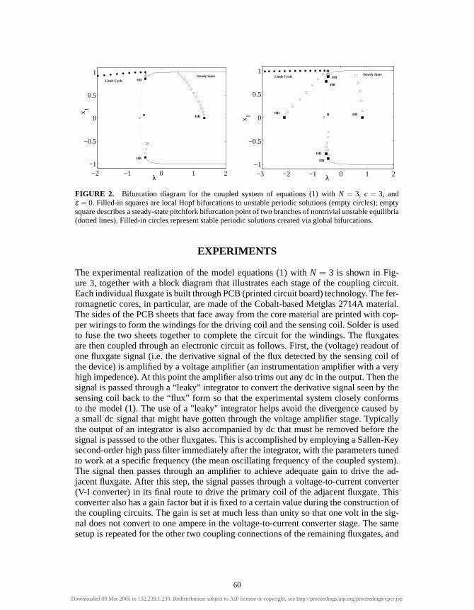
FIGURE 2. Bifurcation diagram for the coupled system of equations (1) with N = 3, c = 3, andε = 0. Filled-in squares are local Hopf bifurcations to unstable periodic solutions (empty circles); emptysquare describes a steady-state pitchfork bifurcation point of two branches of nontrivial unstable equilibria(dotted lines). Filled-in circles represent stable periodic solutions created via global bifurcations.
EXPERIMENTS
The experimental realization of the model equations (1) with N = 3 is shown in Fig-ure 3, together with a block diagram that illustrates each stage of the coupling circuit.Each individual fluxgate is built through PCB (printed circuit board) technology. The fer-romagnetic cores, in particular, are made of the Cobalt-based Metglas 2714A material.The sides of the PCB sheets that face away from the core material are printed with cop-per wirings to form the windings for the driving coil and the sensing coil. Solder is usedto fuse the two sheets together to complete the circuit for the windings. The fluxgatesare then coupled through an electronic circuit as follows. First, the (voltage) readout ofone fluxgate signal (i.e. the derivative signal of the flux detected by the sensing coil ofthe device) is amplified by a voltage amplifier (an instrumentation amplifier with a veryhigh impedence). At this point the amplifier also trims out any dc in the output. Then thesignal is passed through a “leaky” integrator to convert the derivative signal seen by thesensing coil back to the “flux” form so that the experimental system closely conformsto the model (1). The use of a "leaky" integrator helps avoid the divergence caused bya small dc signal that might have gotten through the voltage amplifier stage. Typicallythe output of an integrator is also accompanied by dc that must be removed before thesignal is passsed to the other fluxgates. This is accomplished by employing a Sallen-Keysecond-order high pass filter immediately after the integrator, with the parameters tunedto work at a specific frequency (the mean oscillating frequency of the coupled system).The signal then passes through an amplifier to achieve adequate gain to drive the ad-jacent fluxgate. After this step, the signal passes through a voltage-to-current converter(V-I converter) in its final route to drive the primary coil of the adjacent fluxgate. Thisconverter also has a gain factor but it is fixed to a certain value during the construction ofthe coupling circuits. The gain is set at much less than unity so that one volt in the sig-nal does not convert to one ampere in the voltage-to-current converter stage. The samesetup is repeated for the other two coupling connections of the remaining fluxgates, and
60
Downloaded 09 Mar 2005 to 132.239.1.230. Redistribution subject to AIP license or copyright, see http://proceedings.aip.org/proceedings/cpcr.jsp

all values of the coupling circuit parameters are closely matched from one set to theother. Each stage of the coupling circuit also employs high speed and high precision op-erational amplifiers to minimize the time delay in order to conform closely to the modelsince knowledge of state variable xi is known instantly in the model.
FIGURE 3. (Left) Block diagram of coupling circuit for creating an array of three coupling-induced fluxgate magnetometers; (right) actual prototype device.
The system readily oscillates in a traveling wave pattern, see Figure 4. As in themodel, the system favors this pattern no matter how many times it is restarted. Thefrequency of oscillations is about 57 Hz. Each wave is phase shifted by exactly 2π
3as predicted by the model. Further comparisons with numerical results show goodagreement with the characteristics of the oscillations. Both waveforms are qualitivelysimilar but the waveform from the experiment is a mirror image of the waveform fromthe model. This is probably due to the inversion of the winding of the coils in theconstruction of the fluxgates.
-1
0
1
Am
plitu
de
12x103
1086420
Time (iterates)
5
0
-5
Am
plitu
de
60x10-3
50403020100
Time (second)
FIGURE 4. (Top): Coupling-induced oscillations obtained in simulations of an array of three fluxgatesthrough (1) with c = 4, λ =−1.55, and ε = 0. (Bottom) Results from equivalent experimental system.
In addition, since we do not know the exact value of the parameter c and a timeconstant τ , which arises in the derivation of (1), in the actual device (we set τ = 1 in the
61
Downloaded 09 Mar 2005 to 132.239.1.230. Redistribution subject to AIP license or copyright, see http://proceedings.aip.org/proceedings/cpcr.jsp

model), we cannot correctly compare the time scales in the model and the experimentalobservations. The amplitudes of the oscillations in the experiment are also arbitrarycompared to the model because the recorded voltages depend on the gains set in thecoupling circuit. On the other hand, the magnetic flux in the model saturates between±1, but in the fluxgate devices, this quantity cannot be measured directly. To measurean external signal, we quantify its symmetry-breaking effect through the residence times(RT) ratio around the stable attractors ±1. The critical observation is that the RT ratioin a ring of three fluxgates is about 400 times the RT ratio of a single fluxgate. In otherwords, the ring is (theoretically) three orders of magnitude more sensitive than a singlefluxgate. RT ratio curves are not included in this paper for brevity. In practice, the amountof sensitivity enhancement (without optimization) is about 100 times better. The exactexperimental limit of enhancement is part of on-going work.
ACKNOWLEDGMENTS
The authors acknowledge support from the Office of Naval Research (Code 331). PLand AP were supported in part by the San Diego State Foundation Grant C-2003-00307.
REFERENCES
1. Karlsson, M., Robinson, J., Gammaitoni, L., and Bulsara, A., “The optimal achievable accuracy ofthe Advanced Dynamic Fluxgate Magnetometer (ADFM),” in Proceedings of MARELEC, Stockholm,Sweden, 2001.
2. Koch, R., Deak, J., and Grinstein, G., Applied Physics Letters, 75, 3862–3864 (1999).3. Gordon, D., and Brown, R., IEEE Trans. Magnetics, MAG-8, 76–82 (1972).4. Lenz, J., “A review of magnetic sensors,” in Proceedings IEEE, 1990, vol. 78, p. 973.5. Russell, C., Elphic, R., and Slavin, J., Science, 203, 745 (1979).6. Snare, R., and Means, J., IEEE Trans. Magnetics, MAG-13, 1107–1977 (1997).7. Bulsara, A., In, V., Kho, A., Longhini, P., Palacios, A., Rappel, W., Acebron, J., Baglio, S., and Ando,
B., Physical Review E (2004), in press.8. In, V., Bulsara, A., Palacios, A., Longhini, P., Kho, A., and Neff, J., Physical Review E, 68, 045102–
1–0415102–4 (2003).9. In, V., Kho, A., Neff, J., Palacios, A., Longhini, P., and Meadows, B., Physical Review Letters, 91,
244101–1–244101–4 (2003).
62
Downloaded 09 Mar 2005 to 132.239.1.230. Redistribution subject to AIP license or copyright, see http://proceedings.aip.org/proceedings/cpcr.jsp